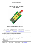
1
Close Talk Central Unit User Manual Revision: 1.08 Copyright 1999 - 2008 Close Talk Marketing AB Author: Göran Ekström Rev. 1.08 All specifications subject to change without prior notice. Revision History: Rev. 1.00 First public release. Applies to Central Unit program version 2.01 or later. Rev. 1.01 Minor corrections. Rev. 1.02 Minor corrections. Rev. 1.03 Minor corrections. Rev. 1.04 Minor corrections. Rev. 1.05 Added description of Microphone Compensation parameter, Telephone Hybrid support and other minor corrections. Rev. 1.06 Added description of rack mounted and table top Central Unit models. Rev. 1.07 Minor corrections. Rev. 1.08 Rev. 1.08 Updated for new box design and firmware version 2.13 and later. Table Of Contents Section 1 Introduction . . . . . . . . . . . . . . . . . . . . . . . . 1 Welcome! . . . . . . . . . . . . . . . . . . . . . . . . . . 3 About this manual . . . . . . . . . . . . . . . . . . . . . . 3 Support. . . . . . . . . . . . . . . . . . . . . . . . . . . . 3 About Close Talk Marketing . . . . . . . . . . . . . . . . 3 System description . . . . . . . . . . . . . . . . . . . . . 4 Section 2 Exterior . . . . . . . . . . . . . . . . . . . . . . . . . . . 5 Front panel . . . . . . . . . . . . . . . . . . . . . . . . . . . . . . . . . . 7 Rear panel . . . . . . . . . . . . . . . . . . . . . . . . . . . . . . . . . . 9 Section 3 Using the front panel. . . . . . . . . . . . . . . . . . . 13 Navigating the menu tree Controls. . . . . . . . Menu structure . . . . Menu level indicator. . Using the controls . . . . . . . . . . . . . . . . . . . . . . . . . . . . . . . . . . . . . . . . . . . . . . . . . . . . . . . . . . . . . . . . . . . . . . . . . . . . . . . . . . . . . . . . . . . . . . . . . . . . . . . . . . . . . . . . . . . . . . . . . . . . . . . . . . . . . 15 15 15 16 16 Section 4 Menu structure . . . . . . . . . . . . . . . . . . . . . . 19 Top level menu . . . . . . Global Audio menu layer . Delegate Units menu layer System menu layer . . . . Lock Unit function . . . . . . . . . . . . . . . . . . . . . . . . . . . . . . . . . . . . . . . . . . . . . . . . . . . . . . . . . . . . . . . . . . . . . . . . . . . . . . . . . . . . . . . . . . . . . . . . . . . . . . . . . . . . . . . . . . . . . . . . . . . . . . . . . . 21 22 23 24 24 Section 5 Rev. 1.08 Settings and functions. . . . . . . . . . . . . . . . . . 25 Global Audio . . . . . . . . . . . . . . . . . . . . . . . . 27 EQ Low . . . . . . . . . . . . . . . . . . . . . . . . . . . . . . . . . . . 27 EQ High . . . . . . . . . . . . . . . . . . . . . . . . . . . . . . . . . . . 27 Delegate Volume . . . . . . . . . . . . . . . . . . . . . . . . . . . . . . 28 i Tele In . . . . . . . . . . . Line In . . . . . . . . . . . Line->Tele Out. . . . . . . Line Out . . . . . . . . . . Microphone Compensation . . . . . . . . . . . . . . . . . . . . . . . . . . . . . . . . . . . . . . . . . . . . . . . . . . . . . . . . . . . . . . . . . . . . . . . . . . . . . . . . . . . . . . . . . . . . . . . . . . . . . . . . . . . . . . . . . . . . . . . . . . . . . 28 29 29 29 30 Delegate Units . . . . . . . . . . . . . . . . . . . . . . . 30 Speaker Volume. . . . Headphones Volume . Delegate Off . . . . . . Delegate Silent . . . . Chairman Unit 1 and 2 Priority Unit . . . . . . Start Update . . . . . . Chairman . . . . . . . Number of Speakers . Chairman Right Key . . . . . . . . . . . . . . . . . . . . . . . . . . . . . . . . . . . . . . . . . . . . . . . . . . . . . . . . . . . . . . . . . . . . . . . . . . . . . . . . . . . . . . . . . . . . . . . . . . . . . . . . . . . . . . . . . . . . . . . . . . . . . . . . . . . . . . . . . . . . . . . . . . . . . . . . . . . . . . . . . . . . . . . . . . . . . . . . . . . . . . . . . . . . . . . . . . . . . . . . . . . . . . . . . . . . . . . . . . . . . . . . . . . . . . . . . . . . . . . . . . . . . . . . . . . . . . . . . . . . . . . . . . . . . . . . 30 31 31 32 32 33 33 34 35 36 System . . . . . . . . . . . . . . . . . . . . . . . . . . . 36 Serial Number . . Security Code . . Backlight. . . . . Firmware version . . . . . . . . . . . . . . . . . . . . . . . . . . . . . . . . . . . . . . . . . . . . . . . . . . . . . . . . . . . . . . . . . . . . . . . . . . . . . . . . . . . . . . . . . . . . . . . . . . . . . . . . . . . . . . . . . . . . . . . . 36 37 37 38 Lock Unit . . . . . . . . . . . . . . . . . . . . . . . . . . 38 Section 6 System description . . . . . . . . . . . . . . . . . . . 39 Overview . . . . . . . . . . . . . . . . . . . . . . . . . . 41 Central Unit . . . . . . . . . . . . . . . . . . . . . . . . . 42 Delegate Unit . . . . . . . . . . . . . . . . . . . . . . . . 43 Audio system. . . . . . . . . . . . . . . . . . . . . . . . 44 Section 7 Specifications . . . . . . . . . . . . . . . . . . . . . . 47 Transmission . . . . . . . . . . . . . . . . . . . . . . . . 49 Audio . . . . . . . . . . . . . . . . . . . . . . . . . . . . 49 General . . . . . . . . . . . . . . . . . . . . . . . . . . . 50 Power . . . . . . . . . . . . . . . . . . . . . . . . . . . . 50 Wall/table and early rack mounted models . . . . . . . . . . . . . . . . . . 50 ii Close Talk Central Unit: Table Of Contents Rev. 1.08 All units . . . . . . . . . . . . . . . . . . . . . . . . . . . . . . . . . . . 49 Wall/table and early rack mounted models . . . . . . . . . . . . . . . . . . 49 Rack and table top units. . . . . . . . . . . . . . . . . . . . . . . . . . . 50 Rack and table top models . . . . . . . . . . . . . . . . . . . . . . . . . 50 Physical. . . . . . . . . . . . . . . . . . . . . . . . . . . 50 Wall/table and early rack mounted models . . . . . . . . . . . . . . . . . . 50 Rack and table top models . . . . . . . . . . . . . . . . . . . . . . . . . 51 Environment . . . . . . . . . . . . . . . . . . . . . . . . 51 Null-modem cable . . . . . . . . . . . . . . . . . . . . . 52 25 pin serial port. . . . . . . . . . . . . . . . . . . . . . . . . . . . . . . 52 9 pin serial port . . . . . . . . . . . . . . . . . . . . . . . . . . . . . . . 52 AUX port . . . . . . . . . . . . . . . . . . . . . . . . . . 53 Audio channel status command protocol . . . . . . . . 54 Rev. 1.08 Introduction . . . . . . . . . . . . . . . . . . . . . . . . . . . . . . . . . 54 Port settings . . . . . . . . . . . . . . . . . . . . . . . . . . . . . . . . . 54 Protocol . . . . . . . . . . . . . . . . . . . . . . . . . . . . . . . . . . . 54 iii Rev. 1.08 Blank page iv Close Talk Central Unit: Table Of Contents Section 1 Rev. 1.08 Introduction Introduction 1 Rev. 1.08 Blank page 2 Close Talk Central Unit: Section 1 Welcome! Thank you for purchasing the Close Talk Conference System. The design philosophy was to make a revolutionary product in both design and productivity, providing a powerful conference tool. We hope it will provide a long time of good use. About this manual The manual is divided into several sections, each focusing on a specific topic: • • • • • • • Introduction This section Exterior A brief description of the unit exterior Using the front panel Tutorial for using the front panel Menu structure An overview of the menu structure Settings and functions Detailed description of the unit settings System description Conference system and system component’s functional description Specifications Central Unit specifications Support Sales questions and support issues should be directed to your local dealer. If you have a specific problem, please check at www.closetalk.se for soft- and firmware updates before contacting support. Updates are available for download free of charge. Rev. 1.08 About Close Talk Marketing Close Talk Marketing AB is a Swedish company responsible for the development and manufacturing of the Close Talk Conference System product range. Close Talk Marketing ships its products using a world wide network of distributors. Check the web site at www.closetalk.se to find a local distributor. We value your input! Please send comments by e-mail to ‘[email protected]’. Welcome! 3 System description A Close Talk Conference System installation consist of a Central Unit (CU), one or more Transceiver Units (TU) and an optional number of Delegate Units (TU). Figure 1. - Central Unit (CU) The CU and DU’s communicate via infra-red light. The CU use one or more TU’s to send and receive data and audio. The DU has a built-in transceiver unit. The system has a total of six channels, 2 data and 4 audio. The CU has 2 transmitters, 1 audio and 1 data, and 4 receivers, 1 data and 3 audio, where FM modulation is used as the information carrier. The FM receivers in the CU and DU provides an FM signal strength level indicator which is monitored by the built-in computer. Figure 1. - Delegate Unit (DU) ‘Close Talk Install’ is available for downloading free of charge from www.closetalk.se. It is intended to be used by qualified installation personnel during installation but is also an efficient way for a local end-user maintenance person to verify system operation independently without the prescence of a qualified technician. 4 Close Talk Central Unit: Section 1 Rev. 1.08 The CU can have 20+ TU’s connected depending on the size and type of room for the installation. Each added TU will alter the noise characteristics for the CU FM receiver’s. A Mute Level is a threshold used internally by the CU to determine whether a channel has an active signal or not, the factory setting will normally work automatically for all systems. During the final testing of a system installation this ML should be checked and if needed, adFigure 1. - Transceiver Unit (TU) justed using the ‘Close Talk Install’ software. This software can also be used to check the communication to and from delegate units and to measure the battery quality in delegate units. Section 2 Rev. 1.08 Exterior Exterior 5 Rev. 1.08 Blank page 6 Close Talk Central Unit: Section 2 Front panel Figure 2.1 shows a generation one wall or table top Central Unit front panel: Indicators Display Rotary knob Buttons Figure 2.1 - Wall/table Central Unit front panel Figure 2.2, a generation two 19 inch rack mounted Central Unit front panel: Display Indicators Rotary knob Buttons Power switch Figure 2.2 - 19 inch rack mounted Central Unit front panel Figure 2.3 shows the table top Central Unit front panel: Display Indicators Buttons Rotary knob Power switch Rev. 1.08 Figure 2.3 - Table top Central Unit front panel 7 Figure 2.4, a generation three 19 inch rack mounted Central Unit front panel: Display Indicators Rotary knob Buttons Power switch Figure 2.4 - 19 inch rack mounted Central Unit front panel The main front panel components are: • • • • Rev. 1.08 • Display 16 characters x 2 lines backlit LCD display. This is where all settings in the Central Unit is shown Indicators Contains three LED indicators that shows the state of the Central Unit where: POWER - Power is applied EDIT - The current setting is in edit mode ERROR - The unit is in an error state Buttons The SELECT and ENTER buttons are used to navigate the menu structure and to change settings Rotary knob Used to navigate the menu structure and to change settings Power button Turns the system on or off. The power of system components such as Split Boxes and Transceivers will also be controlled by this swicth 8 Close Talk Central Unit: Section 2 Rear panel Figure 2.6 shows the legacy wall/table top Central Unit rear panel: Instrument label Power connector Serial port Tele&Line input’s Tele&Line output’s Figure 2.6 - Wall/table Central Unit rear panel Figure 2.7, a generation two 19 inch rack mounted Central Unit rear panel: AUX port Serial port System fuse Insert Unbalanced audio I/O Balanced audio I/O System HF component connectors Power connector Figure 2.7 - 19 inch rack mounted Central Unit rear panel Figure 2.5 shows the table top Central Unit rear panel: Insert Balanced audio I/O Serial port Unbalanced audio I/O Rev. 1.08 AUX port System HF component connectors Power connector System fuse Figure 2.5 - Table top Central Unit rear panel Exterior 9 Figure 2.8, a generation three 19 inch rack mounted Central Unit rear panel: AUX port Serial port System fuse System HF component connectors Insert Balanced audio I/O Unbalanced audio I/O Power connector Figure 2.8 - 19 inch rack mounted Central Unit rear panel • • • • • • • • 10 Instrument label Contains manufacturer information and unit serial number Serial port RS-232 compatible serial port used for firmware updates and remote control AUX port For special applications such as telephone hybrid control (see page 53) Power connector Power input for the unit and the connected HF system units. WARNING! Always use a Close Talk approved power supply. Use of other power supplies may be a fire hazard and can cause permanent damage to the unit and/or other equipment and property System fuse Conference system fuse, replace with same type and rating. Protects the Central Unit and Transceivers connected directly to the Central Unit Balanced and unbalanced Tele&Line inputs Used for teleconferencing and to input other audio signals for distribution in the conference system. Unbalanced inputs use Phono or mono ¼” tele connectors. Balanced inputs use 3 pin XLR connectors. See Specifications on page 47 for more information Balanced and unbalanced Tele&Line outputs Used for teleconferencing and to output the conference system audio for recording and/or distribution. Unbalanced outputs use Phono or mono ¼” tele connectors. Balanced outputs use 3 pin XLR connectors. See Specifications on page 47 for more information Insert Used to insert sound processing equipment into the conference system microphone audio. Stereo ¼” tele connector. See Specifications on page 47 for more information Close Talk Central Unit: Section 2 Rev. 1.08 Rear panel compenents are: System HF component connectors Used to connect conference system HF components such as Transceivers or Split Boxes to the Central Unit. RJ-45 connector. Uses high grade signal cables. WARNING! Only connect Close Talk equipment to these connectors or system damage may occur. Only use approved cable types, NEVER use common network cables such as Cat. 5 or 6 UTP, FTP or STP to connect the system. Usage of non-approved cables will void warranty and system certification. Rev. 1.08 • Exterior 11 Rev. 1.08 Blank Page 12 Close Talk Central Unit: Section 2 Section 3 Rev. 1.08 Using the front panel Using the front panel 13 Rev. 1.08 Blank page 14 Close Talk Central Unit: Section 3 Navigating the menu tree The following part uses the legacy wall/table unit for illustrations but the procedure applies to all Central Unit types. Figure 3.1 shows the Central Unit front panel: CloseTalk Figure 3.1 - Central Unit front panel. The display as it shows after power on. Controls There are three controls used to access the Central Unit settings, the SELECT button, the ENTER button and the rotary encoder knob. Menu structure The menu structure is built as shown in figure 3.2: Menu 1 Menu 2 Menu 3 Submenu 1 Submenu 2 Submenu 3 Menu 4 Value Figure 3.2 - Menu tree design Rev. 1.08 The structure is in a layered-circular fashion. Use the rotary knob to move horizontally. Turn clockwise to move to the right and counter-clockwise to move to the left. Use the SELECT and ENTER keys to move vertically. 15 Menu level indicator Top-right in the display is a menu level indicator as shown in figure 3.3: Global Audio ↓ Figure 3.3 - Menu with submenu available The following indicators are used: • • • ↓ The menu item has sub-menus ↑ The bottom of the menu layer has been reached. The menu value can be edited or its function be used Ε The menu value is being edited Using the controls The SELECT key is used to move down through the menu layers. Pressing SELECT at the menu shown in figure 3.3 will proceed to the next lower layer: EQ Low 0 ↑ Figure 3.4 - Menu with submenu available We are now at the bottom layer as shown by the ↑ indicator in the display. A menu value is now visible on the display’s second line. If the menu item is a function, the ↑ indicator is still shown but the second line may show other information or be blank. To move back up one layer, press the ENTER button. The ENTER button is also used in edit mode to save changes. 16 Close Talk Central Unit: Section 3 Rev. 1.08 To move around the current menu layer, use the knob as described earlier. To change a value, press the SELECT key: EQ Low +2 Ε Figure 3.5 - In edit mode Use the knob to change the setting. Unlike the menu system which is circular, the value has a minimum and maximum limit where the knob stops responding. All editing is ‘live’, i.e. the editing continuously updates the conference system. To abandon the change and restore the original setting, press SELECT. The EDIT lamp is turned off and the menu returns to browse mode. Turning the knob now will move around in the current menu layer as described earlier. To save the new setting, press ENTER. The EDIT lamp is turned off and the new setting is stored. All saved settings are retained after power-off. When pressing the SELECT key and the menu item is a function, one or more function choices are presented: Start Update Version x.yy ↑ Figure 3.6 - The menu item is a function Figure 3.6 shows an example of a function. It is still in browse mode (EDIT lamp is off). Press the SELECT key to enter the function. One or more function alternatives are presented: Start Update Offer Update Ε Rev. 1.08 Figure 3.7 - The menu item is a function Use the knob to select the desired function. Press ENTER to execute the function or SELECT to exit without changes. Using the front panel 17 Rev. 1.08 This concludes the description of the front panel controls. Section 4 and 5 will describe the menu structure and all settings in more detail. 18 Close Talk Central Unit: Section 3 Section 4 Rev. 1.08 Menu structure Menu structure 19 Rev. 1.08 Blank page 20 Close Talk Central Unit: Section 4 Top level menu Figure 4.1 shows the top level of the menu structure: Top menu level Global Audio Delegate Units System Lock Unit Figure 4.1 - Menu system overview The top menu level is the level entered at power on. The following entries are available: • • • Rev. 1.08 • Global Audio Settings for the Central Unit audio system such as equalizer, delegate microphone sound level, Line In and Out levels, Tele In and Out levels and Microphone Compensation Delegate Units Settings regarding the Delegate Units such as speaker and headphones sound levels, power off delay, loose talk channel delay, Chairman unit, Priority unit, firmware update function, chairman channel mode, number of simultaneous speakers and Chairman Right Key System Administrative information and settings for the Central Unit such as serial number, security code, backlight time and firmware version Lock Unit Menu function used to lock the central unit to prevent unauthorized changes 21 Global Audio menu layer Figure 4.2 shows the Global Audio menu layer: Global Audio EQ Low Del. Volume EQ High Line In Tele In Line Out Line->Tele Micr. Comp. Figure 4.2 - Global Audio menu layer The Global Audio menu layer contains settings for the Central Unit audio system. Refer to section 6 on page 39 for more information about the audio system. The following entries are available: • • • • • • • Rev. 1.08 • EQ Low Low frequency boost or cut for the delegate microphone audio EQ High High frequency boost or cut for the delegate microphone audio Delegate Volume Sound level for the delegate microphone audio Tele In Level control for the Tele In rear panel connector Line In Level control for the Line In rear panel connector Line->Tele Out Level control for the Line In to Tele Out cross-coupling Line Out Level control for the Line Out rear panel connector Microphone Compensation Feedback compensation setting 22 Close Talk Central Unit: Section 4 Delegate Units menu layer Figure 4.3 shows the Delegate Units menu layer: Delegate Units Speak. Vol. Del. Off Headp. Vol. Chair. Unit 1&2 Del. Silent Start Update Prio. Unit Num. of Sp. Chairman Chair. R. Key Figure 4.3 - Delegate Units menu layer The Delegate Units menu layer contains settings closely related to the functionality and use of the Delegate Units. The following entries are available: • • • • • • • • • Rev. 1.08 • Speaker Volume Settings for the minimum and maximum speaker sound level for the Delegate Unit Headphones Volume Settings for the minimum and maximum headphones sound level for the Delegate Unit Delegate Off Setting that specifies the Delegate Unit power off time Delegate Silent Setting that specifies the loose audio channel timeout Chairman Unit 1 and 2 Setting that specifies which Delegate Unit to treat as the chairman unit with backup capability Priority Unit Setting that specifies which Delegate Unit to treat as the priority unit Start Update Function for Delegate Unit firmware updates Chairman Setting that selects the Chairman Audio Channel Guarantee method Number of Speakers Setting that specifies the number of available audio channels Chairman Right Key The right key on the chairman unit can have special channel override functionality Menu structure 23 System menu layer Figure 4.4 shows the System menu layer: System Serial Num. Sec. Code Backlight Firmw. Vers. Figure 4.4 - System menu layer The system menu layer contains administrative information and settings for the Central Unit. The following entries are available: • • • • Serial Number Informative. The Central Unit serial number Security Code Security code setting for Central Unit locking Backlight Setting for display backlight timeout Firmware version Informative. Central Unit firmware version Lock Unit function Rev. 1.08 Function used to lock the Central Unit menu system. 24 Close Talk Central Unit: Section 4 Section 5 Rev. 1.08 Settings and functions Settings and functions 25 Rev. 1.08 Blank page 26 Close Talk Central Unit: Section 5 Global Audio The Global Audio menu layer contains settings for the Central Unit Audio system. Refer to section 6 on page 39 for a better understanding of these settings. EQ Low EQ Low 0 ↑ Figure 5.1 - Equalizer low register setting Specifies boost or cut in the low frequency region of the delegate microphone audio signal. Maximum value is +12 and minimum value is -12. Factory setting is 0 (flat response). EQ High EQ High 0 ↑ Figure 5.2 - Equalizer high register setting Specifies boost or cut in the high frequency region of the delegate microphone audio signal. Rev. 1.08 Maximum value is +12 and minimum value is -12. Factory setting is 0 (flat response). Global Audio 27 Delegate Volume Delegate Volume↑ 38 (38) Figure 5.3 - Delegate audio volume Controls the level of the delegate microphone audio signal. Two levels can be specified. The currently active level is selected via the AUX port (see page 53). The setting shown without parantheses is the currently active level. Maximum value is 40 and minimum value is 0. Factory setting is 34 for legacy units and 38 for generation two or later (serial numbers 2000 and higher). NOTE This setting should normally be left at the default setting. To adjust the delegate unit speaker level, use the Speaker Volume setting described on page 30. If the microphone signal needs to be processed externally before sending it back to the delegate units, set this setting to Off, in that way only signals appearing on the Tele- and Line In ports will be sent to the Delegate Unit speakers. Tele In Tele In Off (Off) ↑ Figure 5.4 - Tele In input level Rev. 1.08 Controls the level of the rear panel Tele In input. Two levels can be specified. The currently active level is selected via the AUX port (see page 53). The setting shown without parantheses is the currently active level. Level 35 sets the input to unity gain, maximum value is 39 and minimum value is 0. Factory setting is 0 (input off). 28 Close Talk Central Unit: Section 5 Line In Line In Off (Off) ↑ Figure 5.7 - Line In input level Controls the level of the rear panel Line In input. Two levels can be specified. The currently active level is selected via the AUX port (see page 53). The setting shown without parantheses is the currently active level. Level 36 sets the input to unity gain, maximum value is 39 and minimum value is 0. Factory setting is 0 (input off). Line->Tele Out Line->Tele Out ↑ Off (Off) Figure 5.6 - Line In to Tele Out cross coupling Controls the level of the rear panel Line In to Tele Out cross-coupling. Two levels can be specified. The currently active level is selected via the AUX port (see page 53). The setting shown without parantheses is the currently active level. Maximum value is 39 and minimum value is 0. Factory setting is 0 (cross coupling off). Line Out Line Out 36 (36) ↑ Rev. 1.08 Figure 5.5 - Line Out level control Controls the level of the rear panel Line In to Line Out cross-coupling. Two levels can be specified. The currently active level is selected via the AUX port Settings and functions 29 (see page 53). The setting shown without parantheses is the currently active level. Maximum value is 39 and minimum value is 0. Factory setting is 36. Microphone Compensation Micro. Compens.↑ 2:0 3:0 Figure 5.9 - Microphone Compensation Microphone Compensation is a setting used to compensate for feedback in problem environments such as small rooms with a lot of hard surfaces like walls, ceilings and windows which may reduce the system feedback margin. The Microphone Compensation setting increases the feedback margin by reducing the delegate speaker sound levels depending on the number of active delegate unit microphones. The sound level is controlled by varying the Delegate Volume setting. Reduction can be specified for two (left setting) and three (right setting) active microphones. Factory setting is 0 (no reduction) and maximum reduction is -16. The Level Compensation setting should only be turned on when needed and will require some experimentation for a proper result. Delegate Units Speaker Volume Speaker Volume ↑ 26 26 Delegate Unit’s are equipped with a volume knob that may be used to adjust the delegates speaker- and headphones levels. The Speaker Volume setting specifies the range of this volume knob for the speaker by a minimum and maximum level. 30 Close Talk Central Unit: Section 5 Rev. 1.08 Figure 5.8 - Speaker Volume The range for the minimum and maximum value is 0 to 31. Factory setting is 26 for minimum and 26 for maximum. The delegate unit sound level can be fixed by setting both levels to the same number, effectively disabling the Delegate Unit volume knob. This is usually desired to prevent the end-user from changing the system sound level tuning. Headphones Volume Headphones Vol.↑ 16 26 Figure 5.11 - Headphones Volume Delegate Unit’s are equipped with a volume knob that may be used to adjust the delegates speaker- and headphones levels. The Headphones Volume setting specifies the range of this volume knob for the headphones output by a minimum and maximum level. When the delegate unit senses the insertion of a headphone it will automatically switch to this setting. The range for the minimum and maximum value is 0 to 31. Factory setting is 16 for minimum and 26 for maximum. The function of the Delegate Unit volume knob can be disabled by setting the minimum and maximum value to the same level. Delegate Off Delegate Off 15 Minutes ↑ Rev. 1.08 Figure 5.10 - Delegate power Off The Central Unit can save Delegate Unit battery power with the Delegate Off setting. This timer specifies for how long the system can be in idle before the Delegate Unit’s are turned off. This power off time-out is reset every time a delegate requests to speak. I situations where the system will be left on for a longer period or is used for listen-only, the function can be turned off. The power off time can be set between 1 and 59 minutes or turned off. Factory setting is 15 minutes. Settings and functions 31 Delegate Silent Delegate Silent↑ 5 Minutes Figure 5.13 - Delegate Silent The Delegate Unit contains a microphone signal detector. This detector can be used to make Delegate Unit’s that has an audio channel release it automatically if no one is speaking to preserve battery power and prevent deadlocks. The timeout can be set between 1 and 29 minutes or turned off. Factory setting is 5 minutes. Chairman Unit 1 and 2 Chairman Unit 1↑ 00000000 Figure 5.12 - Chairman Unit The Central Unit can give one Delegate Unit special privileges suitable for the chairman. A Delegate Unit with chairman privileges is always guaranteed an audio channel in a manner specified by the Chairman setting (see page 34) and will bypass the speaking queue. It can also do microphone override as described for the Chairman Right Key setting on page 36. Chairman Unit 1 is the primary chairman unit specifier, Chairman Unit 2 is intended as a backup unit setting. Both settings may be used for dual chairman functionality in an installation but since the primary use is backup, the chairman-overriding-chairman behaviour may not be the desired one, the suitability needs to be verified prior to use. 32 Close Talk Central Unit: Section 5 Rev. 1.08 In order for the Central Unit to know which Delegate Unit to treat as the chairman unit, the Delegate Unit ID number is specified in this setting. Turn the intended chairman Delegate Unit up-side down and enter the unit serial number found on the unit label. Besides the microphone guarantee functionality, the chairman unit is treated as any other Delegate Unit including power-off and Delegate Silent time-out settings. Factory setting is 00000000, i.e. no chairman unit. Priority Unit Priority Unit 00000000 ↑ Figure 5.14 - Priority Unit The Central Unit can give one extra Delegate Unit special privileges. A Delegate Unit with priority privileges is always guaranteed an audio channel by stealing the longest used audio channel if no one is free. It will also bypass the speaking queue. In order for the Central Unit to know which Delegate Unit to treat as the priority unit, the Delegate Unit ID number is specified in this setting. Turn the intended priority Delegate Unit up-side down and enter the unit serial number. Unlike other Delegate Unit’s including chairman, the priority unit will never loose it’s microphone channel, regardless of the Delegate Silent setting. This makes a Priority Unit suitable as a platform microphone. Factory setting is 00000000, i.e. no priority unit. Start Update Start Update Version 2.06 ↑ Rev. 1.08 Figure 5.15 - Delegate Unit firmware update The Central Unit is used to update the firmware in the Delegate Unit’s via the infra-red communication. A copy of the delegate firmware is stored in the Central Unit memory and this function is used for updating. Settings and functions 33 The second line shows the current firmware version stored in the Central Unit. Check with www.closetalk.se regularly to see if there is a newer version available. New versions will often improve performance of the system. The current firmware version is sent over the infra-red data link so Delegate Units with lower versions will recognize this and indicate that they need an update by flashing the vote result LED’s. To update the Delegate Unit’s firmware: • • • • Turn on all Delegate Unit’s to be updated Press SELECT and choose either Offer Update or Force Update. Offer Update will only update Delegate Units with lower firmware versions than the current. Force Update will update all Delegate Unit’s, regardless of the current version number. Force update is normally only used if it is required to install an older firmware version over a newer one Press ENTER. The update starts with a percentage-completed counter in the display. The Delegate Units will flash the vote result LED’s slower during the update After the update function has reached 100%, the Delegate Unit’s will automatically turn them self off if the update was successful. Delegate Unit’s that failed to update will remain powered on, possibly with the LED’s flashing. Verify that the failed units has a clear infra-red communication path. If required, move them closer to a transceiver unit and try again The Delegate Unit firmware copy in the Central Unit is updated with the Microsoft Windows compatible Close Talk Loader software utility which can be downloaded free of charge from www.closetalk.se. A null-modem cable is required to connect the PC to the Central Unit. A connection diagram for a null-modem cable can be found on page 52. Chairman Chairman Steal Channel ↑ One Delegate Unit can have special privileges as described for the Chairman Unit setting. The chairman unit is always guaranteed an audio channel, even if all channels are occupied, using one of three methods. 34 Close Talk Central Unit: Section 5 Rev. 1.08 Figure 5.16 - Chairman Methods available: • • • Steal Channel The chairman will steal the channel from the speaker that has used it’s channel the longest time Borrow Channel The chairman will borrow the channel from the speaker that has used it’s channel the longest time. After the chairman releases the channel, it will be returned to the original speaker Own Channel The chairman will have a dedicated audio channel. This reduces the number of regular audio channels available for other delegate units If the Number of Speakers setting is set to one, the Own Channel method is not available. If so, first increase the number of channels to at least two. Factory setting is Steal Channel. Number of Speakers Number of Speak↑ 3 Figure 5.17 - Number of Speakers The Number of Speakers setting specifies how many audio channels that should be available to the delegate units. Close Talk Conference System can have a maximum of three simultaneous speakers. Use this setting to limit the number of channels. Valid settings are 1 to 3 channels. If the Chairman setting is set to Own channel, the chairman is counted and only the choice of two or three channels is available. Rev. 1.08 Factory setting is 3 channels. Settings and functions 35 Chairman Right Key Chairman R. Key↑ Enabled Figure 5.17 - Chairman Right Key The Chairman Right Key setting is used to control extra features available via the right key on the chairman delegate unit. If this setting is set to Enabled, then depending on the Chairman setting the chairman unit right key functions as follows: • • With Chairman set to Steal or Own By pressing the right key, all currently active delegate units will loose their audio channel permanently and the chairman is given a channel exclusively. The speaker list is blocked until the chairman presses the right key again. With Chairman set to Borrow By pressing the right key, all currently active delegate units will loose their audio channel temporarily and the chairman is given a channel exclusively. The speaker list is blocked until the chairman presses the right key again. Factory default is Enabled. A chairman can go directly from normal discussion using the left microphone request key to microphone override using the right key, simply press the desired key at any time. System Serial Number Serial Number xxxxxxxx ↑ Informative only. Shows the Central Unit’s serial number. 36 Close Talk Central Unit: Section 5 Rev. 1.08 Figure 5.19 - Central Unit serial number Security Code Security Code 0000 ↑ Figure 5.21 - Central Unit serial number The Central Unit settings can be protected with a four digit security code. Enter a code other than 0000 to enable the security system. Enter 0000 to disable it. After entering a valid code, use the Lock Unit function to prevent unauthorized changes to the Central Unit settings. Important! Do not forget the code, unlocking a locked unit requires special tools. Factory setting is 0000, i.e. no protection. Backlight Backlight On ↑ Figure 5.20 - Display backlight time The Central Unit has a backlit LCD display. If a button is pressed or the knob is turned, the backlight is turned on for the duration in this setting. Rev. 1.08 The time can be set from 0 to 59 seconds or On where 0 means that the backlight is always off and On means always on. Factory setting is On. Settings and functions 37 Firmware version Firmware ver. x.yy ↑ Figure 5.23 - Central Unit firmware version Informative only. Shows the Central Unit firmware version. Check with www.closetalk.se regularly to see if there is a newer version available. New versions will often improve performance of the system. The Central Unit firmware is updated with the Microsoft Windows compatible Close Talk Loader software utility which can be downloaded free of charge from www.closetalk.se. A software loader adapter may also be needed to connect the PC to the Central Unit. Contact your dealer for advice. Lock Unit Lock Unit ↑ Figure 5.22 - Lock Central Unit If a valid security code has been specified in the Security Code setting, the Central Unit can be locked to prevent unauthorized changes to the settings. Press SELECT followed by ENTER. The unit is now locked. Pressing any button or turning the knob will prompt for the code. After entering the correct code, press ENTER and the unit is unlocked. Rev. 1.08 Important! Do not forget the code, unlocking a locked unit requires special tools. 38 Close Talk Central Unit: Section 5 Section 6 Rev. 1.08 System description System description 39 Rev. 1.08 Blank page 40 Close Talk Central Unit: Section 6 Overview Figure shows a block diagram of a conference system setup: Transceiver Unit Delegate Unit Transceiver Unit Delegate Unit Delegate Unit Transceiver Unit Delegate Unit Delegate Unit Central Unit PC Figure 6.1 - Conference system block diagram The Central Unit (CU) has one or more Transceiver Unit’s (TU) connected which transmits and receive’s the infra-red light signals to and from the Delegate Unit’s (DU). There are 6 infra-red light channels available in the system: • • • Rev. 1.08 • Global data Transmitted from the CU. Center frequency is 3.61Mhz. Contains administrative communication Global audio Transmitted from the CU. Center frequency is 2.92Mhz. The main audio signal received by the DU’s Audio channel 1 to 3 Transmitted by the DU’s. Center frequency is 4.84MHz (channel 1), 2.38Mhz (channel 2) and 4.36Mhz (channel 3). The microphone audio signal Data channel Transmitted by the DU’s. Center frequency is 5.61Mhz or 5.32MHz. Used for administrative communication An optional PC can be connected to the CU serial port where the Microsoft Windows-compatible software Close Talk Control expands the system functionality with controllable speaker queues, roll-call, voting and more. Overview 41 Central Unit Figure 6.2 shows a block diagram of the Central Unit (CU). The TU’s sends the HF signal via cables down to the FM receivers where the signal is band-pass filtered and demodulated in four channels, Audio 1 to 3 and Data. The three audio channels contains a compressed audio signal which is expanded, mixed and band-pass filtered. The resulting signal is then distributed by the CU audio system where it is mixed with external audio, compressed and transmitted to the DU’s. The data channel is filtered and the data pulse train is extracted. The pulse train is sent to the computer for reconstruction into the system byte stream data protocol. The outgoing system byte stream data protocol is converted by the computer to a pulse train suitable for transmission. The computer also manages the display and controls, control noise gates, audio input- and output levels, mixer levels and communicates with a PC via the serial port. HF Filter FM receiver Audio 1 HF Filter FM receiver Audio 2 HF Filter FM receiver Audio 3 HF Filter FM receiver Data IR Receiver Audio IR transmitter FM modulator Data IR transmitter FM modulator Mixer Expander Bandpass filter Audio Outputs Tele&Line out Audio Inputs with filters Tele&Line in Data signal filter and comparator Compressor Mixer Computer Knob, buttons and display Serial port Rev. 1.08 Figure 6.2 - Central Unit block diagram 42 Close Talk Central Unit: Section 6 Delegate Unit Figure 6.3 shows a block diagram of the Delegate Unit (DU). The infra-red HF signal is received and band-pass filtered by the built-in IR receiver. The resulting signal is sent to the two FM receivers, global audio and data, where it is demodulated. The demodulated audio signal is expanded and band-pass filtered before it is sent to the speaker/headphones amplifier. The amplifier level is controlled by the computer that receives levels and volume knob span information from the CU via the data channel. The data channel is filtered and the data pulse train is extracted. The pulse train is sent to the computer for reconstruction into the system byte stream data protocol. The outgoing system byte stream data protocol is converted by the computer to a pulse train suitable for transmission. The microphone signal is band-pass filtered and compressed before transmission. The computer also manages the buttons, LED indicators and volume knob. Speaker Expander Bandpass filter Speaker amplifier FM receiver Audio IR receiver Microphone Microphone amplifier Bandpass filter Compressor FM modulator IR transmitter Data signal filter and comparator FM receiver Data Computer Rev. 1.08 Volume knob, buttons and indicators Figure 6.3 - Delegate Unit block diagram System description 43 Audio system Figure 6.4 shows the system audio path for the legacy wall/table unit: Audio in 1 Microphone Delegate Transmitter Audio in 3 Speaker/ headphone Delegate Receiver Audio in 2 Audio out Mixer, noise gate and expander Delegate Volume and Equalizer Line Out Volume Mixer Compressor Mixer Tele Out Mixer Line Out Tele In Volume Tele In Line In Volume Line In Line To Tele Volume Figure 6.4 - Legacy wall/table model audio path block diagram This diagram also applies to early versions of the 19 inch rack mounted unit, recognized by the use of Phono audio connectors on the rear panel. Figure 6.5 shows the system audio path for the rack and table top unit: Audio in 1 Microphone Delegate Transmitter Audio in 3 Speaker/ headphone Delegate Receiver Audio in 2 Audio out Mixer, noise gate and expander Delegate Volume and Equalizer Line Out Volume Mixer Limiter * Compressor Mixer Bal+Unbal Tele out Mixer Bal+Unbal Line Out Balan Tele In Tele In Volume Mixer Line In Volume Mixer Unbal Tele In Balan Line In Line To Tele Volume Unbal Line In Figure 6.5 - Rack and table model audio path block diagram Applies to 19 inch rack and table top units shown on page 7 and 9. 44 Close Talk Central Unit: Section 6 Rev. 1.08 Insert The DU microphone signal is sent on 3 channels to the CU where it is expanded and mixed into a single channel main audio path. The main audio is sent straight to the Line Out and Tele Out connectors. The Line Out connector has a level control. The main audio passes through a level control, Delegate Volume (page 28), and equalizer, EQ Low (page 27) and EQ High (page 27). The Line In and Tele In connectors are mixed into the main audio signal via two level controls, Tele In (page 28) and Line In (page 29). For units with balanced and unbalanced connectors, the signals are mixed before the level controls. The main audio is then mixed with incoming Tele and Line signals, limited 1, compressed and transmitted to the DU’s. A cross-coupling function is available where the Tele In signal is mixed into the Line Output after the level control. The Line In signal can be cross-coupled to Tele Out via level control Line->Tele Out (page 29). This built-in cross-coupling feature makes it possible to use a telephone hybrid together with a tape recorder directly without external mixers or patch bays. The level of Line Out can be controlled by the Line Out (page 29) setting. Rev. 1.08 The DU speaker and headphones volume levels can be controlled via the Speaker Volume (page 30) and Headphones Volume (page 31) settings, making the audio system completely controllable from the CU. The microphone level in the DU is fixed. 1 The internal audio limiter is only available on units with serial number 2000 and higher. System description 45 Rev. 1.08 Blank page 46 Close Talk Central Unit: Section 6 Section 7 Rev. 1.08 Specifications Specifications 47 Rev. 1.08 Blank page 48 Close Talk Central Unit: Section 7 All specifications subject to change without prior notice. Specified at 20 degrees centigrade with a 15 minutes system warm-up time. Transmission Media Wavelength Carrier Frequency Infra-red 875nm FM modulation Audio (transmitted) Data (transmitted) Audio 1 (received) Audio 2 (received) Audio 3 (received) Data (received) Data Bit phase modulation 2.92MHz 3.61MHz 4.84MHz 2.38MHz 4.36MHz 5.61MHz (obsolete) 5.32MHz (Nov. 2004-) Audio All units Frequency response Dynamic range THD Line In level Tele In level Line Out level Tele Out level 250Hz - 6kHz (-3dB) > 60dB @ 1kHz < 1% @ 1kHz 500mVRMS nominal @ 1kHz with ‘Line In’ setting set to 36 500mVRMS nominal @ 1kHz with ‘Tele In’ setting set to 35 500mVRMS nominal @ 1kHz with ‘Line Out’ setting set to 36 500mVRMS nominal @ 1kHz Line- and Tele In is peak level controlled by a limiter on units with serial number 2000 and higher. Wall/table and early rack mounted models 20kOhm @ 1kHz 20kOhm @ 1kHz Line Out impedance Tele Out impedance 1kOhm @ 1kHz 1kOhm @ 1kHz Rev. 1.08 Line In impedance Tele In impedance Transmission 49 Rack and table top units Unbal. Line In impedance Bal. Line In impedance Unbal. Tele In impedance Bal. Tele In impedance 10kOhm @ 1kHz 12kOhm @ 1kHz 10kOhm @ 1kHz 12kOhm @ 1kHz Unbal. Line Out impedance Bal. Line Out impedance Unbal. Tele Out impedance Bal. Tele Out impedance 100Ohm @ 1kHz 50Ohm @ 1kHz 100Ohm @ 1kHz 50Ohm @ 1kHz Insert Out level Insert In level Insert Out impedance Insert In impedance 500mVRMS nominal @ 1kHz 500mVRMS nominal @ 1kHz 100Ohm Out (tip) @ 1kHz 12kOhm In (ring) @ 1kHz General Serial port AUX Port Display Firmware update Security RS-232C, 9 pin male D-Sub, DTE device Optional. 9 pin female D-Sub (see AUX port section) 16 characters x 2 lines backlit LCD Via serial port Panel can be locked by PIN-code Power Wall/table and early rack mounted models Power consumption Power requirements 4.3W + transceivers powered by the CU Use only Close Talk approved power supply Rack and table top models Power consumption Power requirements Fuse 10W + transceivers powered by the CU Use only Close Talk approved power supply 4A slow, 5x20mm Physical Dimensions (WxHxD) 234x44x276mm Weight 1.9kg (4.2 lbs) Mounting Wall, Rack Line&Tele connector Phono, unbalanced ¼” mono tele 50 Close Talk Central Unit: Section 7 Rev. 1.08 Wall/table and early rack mounted models Rack and table top models Dimensions (WxDxH) 480x281x44mm (rack). 253x290x93mm (table) Weight 4,5kg/10 lbs (rack). 4,6kg/10 lbs (table) Line&Tele connector Unbalanced ¼” mono tele connectors Balanced outputs male XLR (1=GND, 2=+, 3=-) Balanced inputs female XLR (1=GND, 2=+, 3=-) Insert connector Stereo ¼” tele connector, tip=out and ring=in Environment Temperature 10 to +40 degrees centigrade Rev. 1.08 All specifications subject to change without prior notice Specifications 51 Null-modem cable 25 pin serial port CU Computer Shield Shield Figure 7.1 - 25 pin connector null-modem serial cable 9 pin serial port CU Computer Shield Shield Figure 7.2 - 9 pin connector null-modem serial cable • • • 52 Only use high quality foil shielded cables recommended for data communication Use high quality connectors with, preferably, shielded connector housings Do not exceed the RS-232 specification of a maximum of 15 meters (45 feet) cable length Close Talk Central Unit: Section 7 Rev. 1.08 It is generally recommended to use a purchased null-modem cable. In the event that a longer cable length is needed or if the installation requires it, a custom built cable can be used and should be connected according to the drawings in figure 7.1 and 7.2. AUX port The AUX port is a one in, one out optocoupler isolated control port. It’s main use is together with a telephone hybrid, where the hybrid can select one of the two Central Unit audio settings via the AUX input and the AUX output controls the answer/hangup state of the hybrid. AUX port pins: 1: Input Anode with 390 ohm in series 2: +5VDC, 20 ohm in series 3: NC 4: NC 5: Output collector 6: Input Cathode 7: Ground 8: NC 9: Output emitter Rev. 1.08 Maximum output voltage 24VDC, current 20mADC. Maximum input voltage 24VDC. Output and input is overvoltage and reverse polarity protected with low impedance diode. Specifications 53 Audio channel status command protocol Introduction The serial port on the central unit is normally used for remote control of the entire system. The full control protocol, command syntax and command set is quite large and is not described here. A simple command for reading the current delegate unit ID number for the three audio channels has been added for use in simple control applications such as camera control. The delegate unit ID number is world wide unique which means that some user configurable cross reference table must be provided in order to connect a specific delegate unit to a camera position. Please note that using the serial port for customer specified applications would only be possible when the system is used as stand-alone, i.e. the PC software Close Talk Control cannot be used simultaneously. Contact the local dealer for more information. Port settings The serial port settings are fixed to: • • • • • 9600 Baud Hardware flow control 8 data bits No parity 1 stop bit The serial port pin-out is adapted to commercially available null-modem cables as shown on page 52. Protocol • • • • • 54 Start character 0x01 (1 byte) Message byte counter (1 byte) 24 bit Big Endian Target Unit ID Number (3 bytes) Message specific data portion (1 – 249 bytes) Checksum (1 byte, all message characters summed using signed 8 bits, 2’s complement, -1) Close Talk Central Unit: Section 7 Rev. 1.08 The serial port uses a proprietary binary protocol as follows: The Audio Channel Usage command is as follows: 1, 7, 0, 0, 0, 82, 165 Sending this byte sequence to the central unit will produce an answer in the following format: 1, 16, 0, 0, 0, 82, A1-3, A1-2, A1-1, A2-3, A2-2, A2-1, A3-3, A3-2, A3-1, CS where Ax-y is the channel- and byte number, e.g. A1-3 means audio channel one, byte 3 (bits 16-23). Recreate the 24 bit ID number as ID = (Ax-3)*65536 + (Ax-2)*256 + (Ax-1). Inactive audio channels will show ID as 0. Poll the central unit once per second or slower. The following is an example of a reception with no active audio channels (all ID’s 0): 1, 16, 0, 0, 0, 82, 0, 0, 0, 0, 0, 0, 0, 0, 0, 156 The following is an example of a reception with audio channel one used by a delegate unit with ID number 1716: 1, 16, 0, 0, 0, 82, 0, 6, 180, 0, 0, 0, 0, 0, 0, 226 Rev. 1.08 0 * 65536 + 6 * 256 + 180 = 1716. Audio channels 2 and 3 unused (ID= 0). Checksum updated accordingly. Specifications 55 Rev. 1.08 Blank page 56 Close Talk Central Unit: Section 7 Index A About . . . . . . . . . . . . . . . . . . . . . . . . . . . . . . . . . . . . . 3, 4 Audio system . . . . . . . . . . . . . . . . . . . . . . . . . . . . . . . . . 44 B Backlight . . . . . . . . . . . . . . . . . . . . . . . . . . . . . . . . . . 24, 37 battery . . . . . . . . . . . . . . . . . . . . . . . . . . . . . . . . . . . 31, 32 boost . . . . . . . . . . . . . . . . . . . . . . . . . . . . . . . . . . . . . . 27 Borrow Channel . . . . . . . . . . . . . . . . . . . . . . . . . . . . . . . . 35 Buttons . . . . . . . . . . . . . . . . . . . . . . . . . . . . . . . . . . . . . 8 C Central Unit . . . . . . . . . . . . . . . . . . . . . . . . . . . . . . . . . . . 4 Chairman . . . . . . . . . . . . . . . . . . . . . . . . . . . . . . . 23, 32, 34 Chairman Right Key . . . . . . . . . . . . . . . . . . . . . . . . . . . . 23, 36 Chairman Unit . . . . . . . . . . . . . . . . . . . . . . . . . . . . . 23, 32, 34 Channel Guarantee . . . . . . . . . . . . . . . . . . . . . . . . . . . . . . 23 Close Talk Loader . . . . . . . . . . . . . . . . . . . . . . . . . . . . . 34, 38 Controls . . . . . . . . . . . . . . . . . . . . . . . . . . . . . . . . . . 15, 16 cross-coupling . . . . . . . . . . . . . . . . . . . . . . . . . . . . . . . 29, 45 cut . . . . . . . . . . . . . . . . . . . . . . . . . . . . . . . . . . . . . . . 27 D deadlocks . . . . . . . . . . . . . . . . . . . . . . . . . . . . . . . . . . . 32 Delegate Off . . . . . . . . . . . . . . . . . . . . . . . . . . . . . . . . 23, 31 Delegate Silent . . . . . . . . . . . . . . . . . . . . . . . . . . . . . . 23, 32 Delegate Unit . . . . . . . . . . . . . . . . . . . . . . . . . . . . . . . . . 43 Delegate Units . . . . . . . . . . . . . . . . . . . . . . . . . . . 4, 21, 23, 30 Delegate Volume . . . . . . . . . . . . . . . . . . . . . . . . . . . . . 22, 28 detector . . . . . . . . . . . . . . . . . . . . . . . . . . . . . . . . . . . . 32 disabled . . . . . . . . . . . . . . . . . . . . . . . . . . . . . . . . . . . . 31 Display . . . . . . . . . . . . . . . . . . . . . . . . . . . . . . . . . . . . . 8 Rev. 1.08 E EDIT. . . . . . . . . . . . . . . . . . . . . . . . . . . . . . . . . . . . . 8, 17 ENTER . . . . . . . . . . . . . . . . . . . . . . . . . . . . . . . 8, 15, 16, 17 EQ High . . . . . . . . . . . . . . . . . . . . . . . . . . . . . . . . . . 22, 27 EQ Low . . . . . . . . . . . . . . . . . . . . . . . . . . . . . . . . . . 22, 27 ERROR . . . . . . . . . . . . . . . . . . . . . . . . . . . . . . . . . . . . . 8 i F Feedback . . . . . . . . . . . . . . . . . . . . . . . . . . . . . . . . . 22, 30 firmware . . . . . . . . . . . . . . . . . . . . . . . . . . . . . . . . . . . . 33 Firmware version . . . . . . . . . . . . . . . . . . . . . . . . . . . . . 24, 38 Front panel . . . . . . . . . . . . . . . . . . . . . . . . . . . . . . . . . . . 7 G Global Audio . . . . . . . . . . . . . . . . . . . . . . . . . . . . . . 21, 22, 27 H headphones . . . . . . . . . . . . . . . . . . . . . . . . . . . . . . . . 23, 45 Headphones Volume . . . . . . . . . . . . . . . . . . . . . . . . . . . 23, 31 I ID . . . . . . . . . . . . . . . . . . . . . . . . . . . . . . . . . . . . . 32, 33 Indicators . . . . . . . . . . . . . . . . . . . . . . . . . . . . . . . . . . . . 8 Instrument label . . . . . . . . . . . . . . . . . . . . . . . . . . . . . . . . 10 K knob . . . . . . . . . . . . . . . . . . . . . . . . . . . . . . . 8, 15, 30, 31, 43 L level . . . . . . Line In . . . . . Line Out . . . . Line->Tele Out . listen-only . . . lock . . . . . . Lock Unit . . . . loose . . . . . . . . . . . . . . . . . . . . . . . . . . . . . . . . . . . . . . . . . . . . . . . . . . . . . . . . . . . . . . . . . . . . . . . . . . . . . . . . . . . . . . . . . . . . . . . . . . . . . . . . . . . . . . . . . . . . . . . . . . . . . . . . . . . . . . . . . . . . . . . . . . . . . . . . . . . . . . . . . . . . . . . . . . . . . . . . . . . . . . . . . . . . . . . . . . . . . . . . . . . . . . . . . . . . . . . . . . . . 16 10, 22, 29, 45 10, 22, 29, 45 . . . . 22, 29 . . . . . . 31 . . . . . . 24 21, 24, 37, 38 . . . . . . 33 maximum . . . . . . . . . Menu . . . . . . . . . . . . microphone . . . . . . . . Microphone Compensation minimum . . . . . . . . . . . . . . . . . . . . . . . . . . . . . . . . . . . . . . . . . . . . . . . . . . . . . . . . . . . . . . . . . . . . . . . . . . . . . . . . . . . . . . . . . . . . . . . . . . . . . . . . . . . . 31 . . . . . . . . 15 27, 28, 32, 43, 45 . . . . . . 22, 30 . . . . . . . . 31 Rev. 1.08 M ii Close Talk Central Unit: N Navigating . . . . . . . . . . . . . . . . . . . . . . . . . . . . . . . . . . . 15 null-modem . . . . . . . . . . . . . . . . . . . . . . . . . . . . . . . . . . 34 Number of Speakers . . . . . . . . . . . . . . . . . . . . . . . . . . . . 23, 35 O Overview . . . . . . . . . . . . . . . . . . . . . . . . . . . . . . . . . . . . 41 Own Channel . . . . . . . . . . . . . . . . . . . . . . . . . . . . . . . . . 35 P PC . . . . . . . . . . . . . . . . . . . . . . . . . . . . . . . . . . . . . . . 34 platform . . . . . . . . . . . . . . . . . . . . . . . . . . . . . . . . . . . . 33 POWER . . . . . . . . . . . . . . . . . . . . . . . . . . . . . . . . . . . . . 8 Power connector . . . . . . . . . . . . . . . . . . . . . . . . . . . . . . . . 10 power off . . . . . . . . . . . . . . . . . . . . . . . . . . . . . . . . . . 23, 31 power supply. . . . . . . . . . . . . . . . . . . . . . . . . . . . . . . . . . 10 priority . . . . . . . . . . . . . . . . . . . . . . . . . . . . . . . . . . . 23, 33 Priority Unit . . . . . . . . . . . . . . . . . . . . . . . . . . . . . . . . 23, 33 privileges. . . . . . . . . . . . . . . . . . . . . . . . . . . . . . . . . . 32, 33 Q queue . . . . . . . . . . . . . . . . . . . . . . . . . . . . . . . . . . . . . 32 R range. . . . . . . . . . . . . . . . . . . . . . . . . . . . . . . . . . . . . . 31 Rear panel . . . . . . . . . . . . . . . . . . . . . . . . . . . . . . . . . . . 9 Rev. 1.08 S security. . . . . . . . . . . . . . . . . . . . . . . . . . . . . . . . . . . 37, 38 Security Code . . . . . . . . . . . . . . . . . . . . . . . . . . . . . . . 24, 37 SELECT. . . . . . . . . . . . . . . . . . . . . . . . . . . . . . . 8, 15, 16, 17 Serial Number . . . . . . . . . . . . . . . . . . . . . . . . . . . . . . . 24, 36 Serial port . . . . . . . . . . . . . . . . . . . . . . . . . . . . . . . . . . . 10 simultaneous speakers . . . . . . . . . . . . . . . . . . . . . . . . . . . . 35 speaker . . . . . . . . . . . . . . . . . . . . . . . . . . . . . . . . . . 23, 45 Speaker Volume . . . . . . . . . . . . . . . . . . . . . . . . . . . . . . 23, 30 Start Update . . . . . . . . . . . . . . . . . . . . . . . . . . . . . . . . 23, 33 Steal Channel . . . . . . . . . . . . . . . . . . . . . . . . . . . . . . . . . 35 Support . . . . . . . . . . . . . . . . . . . . . . . . . . . . . . . . . . . . . 3 System . . . . . . . . . . . . . . . . . . . . . . . . . . . . . . . . . 21, 24, 36 iii T Tele In . . . . . . . . . . . . . . . . . . . . . . . . . . . . . . . 10, 22, 28, 45 Tele Out . . . . . . . . . . . . . . . . . . . . . . . . . . . . . . . . . . 10, 45 Top level . . . . . . . . . . . . . . . . . . . . . . . . . . . . . . . . . . . . 21 Transceiver Units . . . . . . . . . . . . . . . . . . . . . . . . . . . . . . . . 4 U update . . . . . . . . . . . . . . . . . . . . . . . . . . . . . . . . . . . 33, 34 W Welcome . . . . . . . . . . . . . . . . . . . . . . . . . . . . . . . . . . . . 3 V Rev. 1.08 version . . . . . . . . . . . . . . . . . . . . . . . . . . . . . . . . . . . . . 34 iv Close Talk Central Unit: