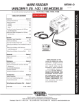
1
RETURN TO MAIN MENU
IM890-A
POWER MIG (140, 180 MODELS)
For use with machines having Code Numbers:
May, 2007
11254, 11255, 11256, 11257 and
11444
Safety Depends on You
Lincoln arc welding and cutting
equipment is designed and built
with safety in mind. However, your
overall safety can be increased by
proper installation ... and thoughtful operation on your part. DO
NOT INSTALL, OPERATE OR
REPAIR THIS EQUIPMENT
WITHOUT READING THIS
MANUAL AND THE SAFETY
PRECAUTIONS CONTAINED
THROUGHOUT. And, most
importantly, think before you act
and be careful.
LN
COCTRIC
N
I
E
L
EL
OPERATOR’S MANUAL
Copyright © 2007 Lincoln Global Inc.
• World's Leader in Welding and Cutting Products •
• Sales and Service through Subsidiaries and Distributors Worldwide •
Cleveland, Ohio 44117-1199 U.S.A. TEL: 216.481.8100 FAX: 216.486.1751 WEB SITE: www.lincolnelectric.com
SAFETY
i
i
WARNING
CALIFORNIA PROPOSITION 65 WARNINGS
Diesel engine exhaust and some of its constituents
are known to the State of California to cause cancer, birth defects, and other reproductive harm.
The Above For Diesel Engines
The engine exhaust from this product contains
chemicals known to the State of California to cause
cancer, birth defects, or other reproductive harm.
The Above For Gasoline Engines
ARC WELDING CAN BE HAZARDOUS. PROTECT YOURSELF AND OTHERS FROM POSSIBLE SERIOUS INJURY OR DEATH.
KEEP CHILDREN AWAY. PACEMAKER WEARERS SHOULD CONSULT WITH THEIR DOCTOR BEFORE OPERATING.
Read and understand the following safety highlights. For additional safety information, it is strongly recommended that you
purchase a copy of “Safety in Welding & Cutting - ANSI Standard Z49.1” from the American Welding Society, P.O. Box
351040, Miami, Florida 33135 or CSA Standard W117.2-1974. A Free copy of “Arc Welding Safety” booklet E205 is available
from the Lincoln Electric Company, 22801 St. Clair Avenue, Cleveland, Ohio 44117-1199.
BE SURE THAT ALL INSTALLATION, OPERATION, MAINTENANCE AND REPAIR PROCEDURES ARE
PERFORMED ONLY BY QUALIFIED INDIVIDUALS.
FOR ENGINE
powered equipment.
1.h. To avoid scalding, do not remove the
radiator pressure cap when the engine is
hot.
1.a. Turn the engine off before troubleshooting and maintenance
work unless the maintenance work requires it to be running.
____________________________________________________
1.b. Operate engines in open, well-ventilated
areas or vent the engine exhaust fumes
outdoors.
____________________________________________________
1.c. Do not add the fuel near an open flame
welding arc or when the engine is running.
Stop the engine and allow it to cool before
refueling to prevent spilled fuel from vaporizing on contact with hot engine parts and
igniting. Do not spill fuel when filling tank. If
fuel is spilled, wipe it up and do not start
engine until fumes have been eliminated.
____________________________________________________
1.d. Keep all equipment safety guards, covers and devices in
position and in good repair.Keep hands, hair, clothing and
tools away from V-belts, gears, fans and all other moving
parts when starting, operating or repairing equipment.
____________________________________________________
1.e. In some cases it may be necessary to remove safety
guards to perform required maintenance. Remove
guards only when necessary and replace them when the
maintenance requiring their removal is complete.
Always use the greatest care when working near moving
parts.
___________________________________________________
1.f. Do not put your hands near the engine fan.
Do not attempt to override the governor or
idler by pushing on the throttle control rods
while the engine is running.
___________________________________________________
1.g. To prevent accidentally starting gasoline engines while
turning the engine or welding generator during maintenance
work, disconnect the spark plug wires, distributor cap or
magneto wire as appropriate.
ELECTRIC AND
MAGNETIC FIELDS
may be dangerous
2.a. Electric current flowing through any conductor causes
localized Electric and Magnetic Fields (EMF). Welding
current creates EMF fields around welding cables and
welding machines
2.b. EMF fields may interfere with some pacemakers, and
welders having a pacemaker should consult their physician
before welding.
2.c. Exposure to EMF fields in welding may have other health
effects which are now not known.
2.d. All welders should use the following procedures in order to
minimize exposure to EMF fields from the welding circuit:
2.d.1. Route the electrode and work cables together - Secure
them with tape when possible.
2.d.2. Never coil the electrode lead around your body.
2.d.3. Do not place your body between the electrode and
work cables. If the electrode cable is on your right
side, the work cable should also be on your right side.
2.d.4. Connect the work cable to the workpiece as close as
possible to the area being welded.
2.d.5. Do not work next to welding power source.
Mar ʻ95
ii
SAFETY
ELECTRIC SHOCK can
kill.
3.a. The electrode and work (or ground) circuits
are electrically “hot” when the welder is on.
Do not touch these “hot” parts with your bare
skin or wet clothing. Wear dry, hole-free
gloves to insulate hands.
3.b. Insulate yourself from work and ground using dry insulation.
Make certain the insulation is large enough to cover your full
area of physical contact with work and ground.
In addition to the normal safety precautions, if welding
must be performed under electrically hazardous
conditions (in damp locations or while wearing wet
clothing; on metal structures such as floors, gratings or
scaffolds; when in cramped positions such as sitting,
kneeling or lying, if there is a high risk of unavoidable or
accidental contact with the workpiece or ground) use
the following equipment:
• Semiautomatic DC Constant Voltage (Wire) Welder.
• DC Manual (Stick) Welder.
• AC Welder with Reduced Voltage Control.
3.c. In semiautomatic or automatic wire welding, the electrode,
electrode reel, welding head, nozzle or semiautomatic
welding gun are also electrically “hot”.
3.d. Always be sure the work cable makes a good electrical
connection with the metal being welded. The connection
should be as close as possible to the area being welded.
3.e. Ground the work or metal to be welded to a good electrical
(earth) ground.
3.f. Maintain the electrode holder, work clamp, welding cable and
welding machine in good, safe operating condition. Replace
damaged insulation.
3.g. Never dip the electrode in water for cooling.
3.h. Never simultaneously touch electrically “hot” parts of
electrode holders connected to two welders because voltage
between the two can be the total of the open circuit voltage
of both welders.
3.i. When working above floor level, use a safety belt to protect
yourself from a fall should you get a shock.
3.j. Also see Items 6.c. and 8.
ARC RAYS can burn.
ii
4.a. Use a shield with the proper filter and cover
plates to protect your eyes from sparks and
the rays of the arc when welding or observing
open arc welding. Headshield and filter lens
should conform to ANSI Z87. I standards.
4.b. Use suitable clothing made from durable flame-resistant
material to protect your skin and that of your helpers from
the arc rays.
4.c. Protect other nearby personnel with suitable, non-flammable
screening and/or warn them not to watch the arc nor expose
themselves to the arc rays or to hot spatter or metal.
FUMES AND GASES
can be dangerous.
5.a. Welding may produce fumes and gases
hazardous to health. Avoid breathing these
fumes and gases. When welding, keep
your head out of the fume. Use enough
ventilation and/or exhaust at the arc to keep
fumes and gases away from the breathing zone. When
welding with electrodes which require special
ventilation such as stainless or hard facing (see
instructions on container or MSDS) or on lead or
cadmium plated steel and other metals or coatings
which produce highly toxic fumes, keep exposure as
low as possible and below Threshold Limit Values (TLV)
using local exhaust or mechanical ventilation. In
confined spaces or in some circumstances, outdoors, a
respirator may be required. Additional precautions are
also required when welding on galvanized steel.
5. b. The operation of welding fume control equipment is affected
by various factors including proper use and positioning of
the equipment, maintenance of the equipment and the specific welding procedure and application involved. Worker
exposure level should be checked upon installation and
periodically thereafter to be certain it is within applicable
OSHA PEL and ACGIH TLV limits.
5.c. Do not weld in locations near chlorinated hydrocarbon vapors
coming from degreasing, cleaning or spraying operations.
The heat and rays of the arc can react with solvent vapors to
form phosgene, a highly toxic gas, and other irritating products.
5.d. Shielding gases used for arc welding can displace air and
cause injury or death. Always use enough ventilation,
especially in confined areas, to insure breathing air is safe.
5.e. Read and understand the manufacturerʼs instructions for this
equipment and the consumables to be used, including the
material safety data sheet (MSDS) and follow your
employerʼs safety practices. MSDS forms are available from
your welding distributor or from the manufacturer.
5.f. Also see item 1.b.
AUG 06
iii
SAFETY
WELDING and CUTTING
SPARKS can
cause fire or explosion.
6.a. Remove fire hazards from the welding area.
If this is not possible, cover them to prevent
the welding sparks from starting a fire.
Remember that welding sparks and hot
materials from welding can easily go through small cracks
and openings to adjacent areas. Avoid welding near
hydraulic lines. Have a fire extinguisher readily available.
6.b. Where compressed gases are to be used at the job site,
special precautions should be used to prevent hazardous
situations. Refer to “Safety in Welding and Cutting” (ANSI
Standard Z49.1) and the operating information for the
equipment being used.
6.c. When not welding, make certain no part of the electrode
circuit is touching the work or ground. Accidental contact
can cause overheating and create a fire hazard.
6.d. Do not heat, cut or weld tanks, drums or containers until the
proper steps have been taken to insure that such procedures
will not cause flammable or toxic vapors from substances
inside. They can cause an explosion even though they have
been “cleaned”. For information, purchase “Recommended
Safe Practices for the Preparation for Welding and Cutting of
Containers and Piping That Have Held Hazardous
Substances”, AWS F4.1 from the American Welding Society
(see address above).
6.e. Vent hollow castings or containers before heating, cutting or
welding. They may explode.
6.f. Sparks and spatter are thrown from the welding arc. Wear oil
free protective garments such as leather gloves, heavy shirt,
cuffless trousers, high shoes and a cap over your hair. Wear
ear plugs when welding out of position or in confined places.
Always wear safety glasses with side shields when in a
welding area.
6.g. Connect the work cable to the work as close to the welding
area as practical. Work cables connected to the building
framework or other locations away from the welding area
increase the possibility of the welding current passing
through lifting chains, crane cables or other alternate circuits. This can create fire hazards or overheat lifting chains
or cables until they fail.
6.h. Also see item 1.c.
6.I. Read and follow NFPA 51B “ Standard for Fire Prevention
During Welding, Cutting and Other Hot Work”, available
from NFPA, 1 Batterymarch Park,PO box 9101, Quincy, Ma
022690-9101.
6.j. Do not use a welding power source for pipe thawing.
CYLINDER may explode
if damaged.
iii
7.a. Use only compressed gas cylinders
containing the correct shielding gas for the
process used and properly operating
regulators designed for the gas and
pressure used. All hoses, fittings, etc. should be suitable for
the application and maintained in good condition.
7.b. Always keep cylinders in an upright position securely
chained to an undercarriage or fixed support.
7.c. Cylinders should be located:
• Away from areas where they may be struck or subjected to
physical damage.
• A safe distance from arc welding or cutting operations and
any other source of heat, sparks, or flame.
7.d. Never allow the electrode, electrode holder or any other
electrically “hot” parts to touch a cylinder.
7.e. Keep your head and face away from the cylinder valve outlet
when opening the cylinder valve.
7.f. Valve protection caps should always be in place and hand
tight except when the cylinder is in use or connected for
use.
7.g. Read and follow the instructions on compressed gas
cylinders, associated equipment, and CGA publication P-l,
“Precautions for Safe Handling of Compressed Gases in
Cylinders,” available from the Compressed Gas Association
1235 Jefferson Davis Highway, Arlington, VA 22202.
FOR ELECTRICALLY
powered equipment.
8.a. Turn off input power using the disconnect
switch at the fuse box before working on
the equipment.
8.b. Install equipment in accordance with the U.S. National
Electrical Code, all local codes and the manufacturerʼs
recommendations.
8.c. Ground the equipment in accordance with the U.S. National
Electrical Code and the manufacturerʼs recommendations.
Jan, 07
iv
PRÉCAUTIONS DE SÛRETÉ
SAFETY
Pour votre propre protection lire et observer toutes les instructions
et les précautions de sûreté specifiques qui parraissent dans ce
manuel aussi bien que les précautions de sûreté générales suivantes:
Sûreté Pour Soudage A LʼArc
1. Protegez-vous contre la secousse électrique:
a. Les circuits à lʼélectrode et à la piéce sont sous tension
quand la machine à souder est en marche. Eviter toujours
tout contact entre les parties sous tension et la peau nue
ou les vétements mouillés. Porter des gants secs et sans
trous pour isoler les mains.
b. Faire trés attention de bien sʼisoler de la masse quand on
soude dans des endroits humides, ou sur un plancher
metallique ou des grilles metalliques, principalement dans
les positions assis ou couché pour lesquelles une grande
partie du corps peut être en contact avec la masse.
c. Maintenir le porte-électrode, la pince de masse, le câble
de soudage et la machine à souder en bon et sûr état
defonctionnement.
d.Ne jamais plonger le porte-électrode dans lʼeau pour le
refroidir.
e. Ne jamais toucher simultanément les parties sous tension
des porte-électrodes connectés à deux machines à souder
parce que la tension entre les deux pinces peut être le
total de la tension à vide des deux machines.
f. Si on utilise la machine à souder comme une source de
courant pour soudage semi-automatique, ces precautions
pour le porte-électrode sʼapplicuent aussi au pistolet de
soudage.
2. Dans le cas de travail au dessus du niveau du sol, se protéger
contre les chutes dans le cas ou on recoit un choc. Ne jamais
enrouler le câble-électrode autour de nʼimporte quelle partie
du corps.
3. Un coup dʼarc peut être plus sévère quʼun coup de soliel,
donc:
a. Utiliser un bon masque avec un verre filtrant approprié
ainsi quʼun verre blanc afin de se protéger les yeux du rayonnement de lʼarc et des projections quand on soude ou
quand on regarde lʼarc.
b. Porter des vêtements convenables afin de protéger la
peau de soudeur et des aides contre le rayonnement de
lʻarc.
c. Protéger lʼautre personnel travaillant à proximité au
soudage à lʼaide dʼécrans appropriés et non-inflammables.
4. Des gouttes de laitier en fusion sont émises de lʼarc de
soudage. Se protéger avec des vêtements de protection libres
de lʼhuile, tels que les gants en cuir, chemise épaisse, pantalons sans revers, et chaussures montantes.
iv
5. Toujours porter des lunettes de sécurité dans la zone de
soudage. Utiliser des lunettes avec écrans lateraux dans les
zones où lʼon pique le laitier.
6. Eloigner les matériaux inflammables ou les recouvrir afin de
prévenir tout risque dʼincendie dû aux étincelles.
7. Quand on ne soude pas, poser la pince à une endroit isolé de
la masse. Un court-circuit accidental peut provoquer un
échauffement et un risque dʼincendie.
8. Sʼassurer que la masse est connectée le plus prés possible
de la zone de travail quʼil est pratique de le faire. Si on place
la masse sur la charpente de la construction ou dʼautres
endroits éloignés de la zone de travail, on augmente le risque
de voir passer le courant de soudage par les chaines de levage, câbles de grue, ou autres circuits. Cela peut provoquer
des risques dʼincendie ou dʼechauffement des chaines et des
câbles jusquʼà ce quʼils se rompent.
9. Assurer une ventilation suffisante dans la zone de soudage.
Ceci est particuliérement important pour le soudage de tôles
galvanisées plombées, ou cadmiées ou tout autre métal qui
produit des fumeés toxiques.
10. Ne pas souder en présence de vapeurs de chlore provenant
dʼopérations de dégraissage, nettoyage ou pistolage. La
chaleur ou les rayons de lʼarc peuvent réagir avec les vapeurs
du solvant pour produire du phosgéne (gas fortement toxique)
ou autres produits irritants.
11. Pour obtenir de plus amples renseignements sur la sûreté,
voir le code “Code for safety in welding and cutting” CSA
Standard W 117.2-1974.
PRÉCAUTIONS DE SÛRETÉ POUR
LES MACHINES À SOUDER À
TRANSFORMATEUR ET À
REDRESSEUR
1. Relier à la terre le chassis du poste conformement au code de
lʼélectricité et aux recommendations du fabricant. Le dispositif
de montage ou la piece à souder doit être branché à une
bonne mise à la terre.
2. Autant que possible, Iʼinstallation et lʼentretien du poste seront
effectués par un électricien qualifié.
3. Avant de faires des travaux à lʼinterieur de poste, la debrancher à lʼinterrupteur à la boite de fusibles.
4. Garder tous les couvercles et dispositifs de sûreté à leur
place.
Mar. ʻ93
INSTALLATION
v
EN 60974-10
POWER MIG (140, 180 MODELS)
v
vi
INSTALLATION
EN 60974-10:
POWER MIG (140, 180 MODELS)
vi
vii
Thank You
vii
for selecting a QUALITY product by Lincoln Electric. We want you
to take pride in operating this Lincoln Electric Company product
••• as much pride as we have in bringing this product to you!
CUSTOMER ASSISTANCE POLICY
The business of The Lincoln Electric Company is manufacturing and selling high quality welding equipment, consumables, and cutting equipment. Our challenge is to meet the needs of our customers and to exceed their expectations. On occasion, purchasers may ask Lincoln
Electric for advice or information about their use of our products. We respond to our customers based on the best information in our possession at that time. Lincoln Electric is not in a position to warrant or guarantee such advice, and assumes no liability, with respect to such information or advice. We expressly disclaim any warranty of any kind, including any warranty of fitness for any customerʼs particular purpose,
with respect to such information or advice. As a matter of practical consideration, we also cannot assume any responsibility for updating or
correcting any such information or advice once it has been given, nor does the provision of information or advice create, expand or alter any
warranty with respect to the sale of our products.
Lincoln Electric is a responsive manufacturer, but the selection and use of specific products sold by Lincoln Electric is solely within the control
of, and remains the sole responsibility of the customer. Many variables beyond the control of Lincoln Electric affect the results obtained in
applying these types of fabrication methods and service requirements.
Subject to Change – This information is accurate to the best of our knowledge at the time of printing. Please refer to www.lincolnelectric.com
for any updated information.
Please Examine Carton and Equipment For Damage Immediately
When this equipment is shipped, title passes to the purchaser upon receipt by the carrier. Consequently, Claims
for material damaged in shipment must be made by the purchaser against the transportation company at the
time the shipment is received.
Please record your equipment identification information below for future reference. This information can be
found on your machine nameplate.
Product _________________________________________________________________________________
Model Number ___________________________________________________________________________
Code Number or Date Code_________________________________________________________________
Serial Number____________________________________________________________________________
Date Purchased___________________________________________________________________________
Where Purchased_________________________________________________________________________
Whenever you request replacement parts or information on this equipment, always supply the information you
have recorded above. The code number is especially important when identifying the correct replacement parts.
On-Line Product Registration
- Register your machine with Lincoln Electric either via fax or over the Internet.
• For faxing: Complete the form on the back of the warranty statement included in the literature packet
accompanying this machine and fax the form per the instructions printed on it.
• For On-Line Registration: Go to our WEB SITE at www.lincolnelectric.com. Choose “Quick Links” and then
“Product Registration”. Please complete the form and submit your registration.
Read this Operators Manual completely before attempting to use this equipment. Save this manual and keep it
handy for quick reference. Pay particular attention to the safety instructions we have provided for your protection.
The level of seriousness to be applied to each is explained below:
WARNING
This statement appears where the information must be followed exactly to avoid serious personal injury or loss of life.
CAUTION
This statement appears where the information must be followed to avoid minor personal injury or damage to this equipment.
viii
TABLE OF CONTENTS
Page
––––––––––––––––––––––––––––––––––––––––––––––––––––––––––––––––––––––––––––––––
Installation .......................................................................................................Section A
Technical Specifications.................................................................................A-1, A-2
Safety Precautions.................................................................................................A-3
Location...........................................................................................................A-3
Stacking ..........................................................................................................A-3
Tilting...............................................................................................................A-3
Identify and Locate Components ...........................................................................A-4
________________________________________________________________________________
Operation .........................................................................................................Section B
Safety and Product Description .............................................................................B-1
Controls and Settings.....................................................................................B-2, B-3
Drive Roll and Wire Guides Table .........................................................................B-4
Setting Up and Making a Flux-Cored Weld.............................................B-5 thru B-7
Setting Up and Making a MIG Weld and Install Shielding Gas..............B-8 thru B-11
Setting Up and Making a Aluminum Weld ...........................................................B-12
________________________________________________________________________
Accessories .....................................................................................................Section C
Optional Accessories.............................................................................................C-1
Utility Carts ....................................................................................................C-2, C-3
________________________________________________________________________
Maintenance ..............................................................................................Section D
Safety Precautions ................................................................................................D-1
Wire Feed Compartment, Fan Motor, Wire Reel Maintenance .............................D-1
Gun And Cable Maintenance ................................................................................D-2
Overload Protection...............................................................................................D-2
Component Replacement Procedures ..................................................................D-3
________________________________________________________________________
Troubleshooting ..............................................................................................Section E
Safety Precautions.................................................................................................E-1
How to Use Troubleshooting Guide.......................................................................E-1
Troubleshooting Guide.............................................................................E-2 thru E-4
________________________________________________________________________
Wiring Diagram and Dimension Print ............................................................Section F
________________________________________________________________________
Parts Lists................................................................................................P-533, P-202-E
________________________________________________________________________
viii
INSTALLATION
A-1
TECHNICAL SPECIFICATIONS
A-1
180 Amp units (K2472-1 180T, K2473-1 180C)
INPUT – SINGLE PHASE ONLY
Standard Voltage/Frequency
230 V
60 Hz
208 V
60 Hz
Input Current
20 Amps @ rated output
20 Amps @ rated output
RATED OUTPUT
Voltage/Duty Cycle
230 V
30%
208 V
30%
Current
130 Amps
130 Amps
Voltage at Rated Amperes
20
17
Open Circuit Voltage
34 V
Wire Speed Range
50 - 500 in/min.
(1.3 - 12.7 m/min.)
OUTPUT
Welding Current Range
30-180 Amps
RECOMMENDED INPUT CABLE AND FUSE SIZES
Input Voltage/Frequency
230 V
1 If
60 Hz
Fuse or Breaker Size1
Input Amps
40 Amp Super Lag
Power Cord
20
50 Amp, 250 V,
Three Prong Plug
(NEMA Type 6-50P)
PHYSICAL DIMENSIONS
Height
14.0 in
357 mm
Width
10.15 in
258 mm
connected to a circuit protected by fuses use Time Delay Fuse marked “D”.
Depth
18.6 in
472 mm
Weight
66 Ibs
30 kg
140 Amp units (K2470-1 140T, K2471-1 140C)
Standard Voltage/Frequency
120 V / 60 Hz
INPUT – SINGLE PHASE ONLY
Input Current
20 Amps @ rated output
RATED OUTPUT
Duty Cycle
20% Duty Cycle
Current
90 Amps
Voltage at Rated Amperes
19.5
Open Circuit Voltage
33 V
Wire Speed Range
50 - 500 in/min.
(1.3 - 12.7 m/min.)
OUTPUT
Welding Current Range
30-140 Amps
RECOMMENDED INPUT CABLE AND FUSE SIZES
Input Voltage/Frequency Fuse or Breaker Size1,2 Input Amps
120 V
1If
60 Hz
Height
14.0 in
357 mm
20 Amp
20
Power Cord
15 Amp, 125 V,
Three Prong Plug
(NEMA Type 5-15P)
PHYSICAL DIMENSIONS
Width
10.15 in
258 mm
connected to a circuit protected by fuses use Time Delay Fuse marked “D”.
Depth
18.6 in
472 mm
POWER MIG (140, 180 MODELS)
Extension Cord
3 Conductor # 12 AWG
(4mm2) or Larger
up to 50 ft.(15.2m)
Weight
58 Ibs
26.3 kg
INSTALLATION
A-2
TECHNICAL SPECIFICATIONS
180 Amp units (K2668-1 180C)
A-2
INPUT – SINGLE PHASE ONLY
Standard Voltage/Frequency
240 V
50 Hz
Voltage/Duty Cycle
240 V
25%
RATED OUTPUT
Current
130 Amps
Input Current
I1 max 20 Amps
I1 eff 10.7 Amps
OUTPUT
Welding Current Range
30 - 180 Amps
Open Circuit Voltage
34 V
Voltage at Rated Amperes
20
Wire Speed Range
50 - 500 in/min.
1.3 - 12.7 ( m/min.)
RECOMMENDED INPUT CABLE AND FUSE SIZES
Input Voltage/Frequency
240 V
1 If
50 Hz
Height
14.0 in
357 mm
Fuse or Breaker Size1
40 Amp Super Lag
Input Amps
PHYSICAL DIMENSIONS
Width
10.15 in
258 mm
connected to a circuit protected by fuses use Time Delay Fuse marked “D”.
2 Requirements
20
For Maximum Output
Depth
18.6 in
472 mm
In order to utilize the maximum output capability of
the machine, a branch circuit capable of 25 amps at
120 volts, 60 Hertz is required.
POWER MIG (140, 180 MODELS)
Power Cord
15 Amp, 240 V,
Three Pin Plug
Weight
66 Ibs
30 kg
A-3
INSTALLATION
Read entire installation section before starting
installation.
SAFETY PRECAUTIONS
WARNING
ELECTRIC SHOCK can kill.
• Only qualified personnel should perform
this installation.
• Only personnel that have read and understood the POWER MIG Operating Manual
should install and operate this equipment.
• Machine must be plugged into a receptacle
which is grounded per any national, local
or other applicable electrical codes.
• The POWER MIG power switch is to be in
the OFF (“O”) position when installing
work cable and gun and when connecting
power cord to input power.
SELECT SUITABLE LOCATION
Locate the welder in a dry location where there is free
circulation of clean air into the louvers in the back and
out the front of the unit. A location that minimizes the
amount of smoke and dirt drawn into the rear louvers
reduces the chance of dirt accumulation that can
block air passages and cause overheating.
STACKING
POWER MIG (140, 180 MODELS) cannot be stacked.
TILTING
Each machine must be placed on a secure, level surface, directly or on recommended cart. The machine
may topple over if this procedure is not followed.
POWER MIG (140, 180 MODELS)
A-3
INSTALLATION
A-4
IDENTIFY AND LOCATE COMPONENTS
INCLUDED COMPONENTS
• .030” -.045” (0.8 - 1.1mm) Knurled Drive Roll
(Installed on Machine)
.045
.030
• Wire Feeder Welder.
A-4
• .025” -.035” (0.6 - 0.9mm) Inner Wire guide
• .035” -.045” (0.9 - 1.1mm) Inner Wire Guide
(Installed on Machine)
• Outer Wire Guide (Installed on Machine)
INNER WIRE GUIDE
.025-.035 (.6-.9mm)
• Work Cable & Clamp.
• Brass MIG Gas Gun Nozzle
.025
.025
.025
.035
.035
• 3 .035” (0.9mm) Contact Tips
(1 installed on the welding gun).
• 3 .025” (0.6mm) Contact Tips.
• Spool of .035” (0.9 mm) diameter NR-211MP
Innershield Flux-cored Wire.
• Spool of .025” (0.6 mm) diameter L-56 MIG Wire.
• .025”-.030” (0.6 - 0.8mm)
Smooth Drive Roll
OUTER WIRE GUIDE
• Black Flux-cored Gasless Gun Nozzle (Installed on
Welding Gun)
• Magnum 100L Welding Gun.
NR-211 MP
INNER WIRE GUIDE
.035-.045 (.9-1.1mm)
L-56 MIG
WIRE
• 2”(51mm) Spindle Adapter (For 8”(203mm) Reel of
wire)
• Regulator
• Gas Hose
• Learn to Weld (LTW1 Manual)
• DVD
REGULATOR
• .035” (0.9mm)
Smooth Drive Roll
2" SPINDLE ADAPTER (FOR 8" REEL OF WIRE)
GAS HOSE
"LEARN TO WELD"
LTW1
DVD
POWER MIG (140, 180 MODELS)
OPERATION
B-1
Read entire operation section before
operating the POWER MIG.
WARNING
ELECTRIC SHOCK can kill.
• Do not touch electrically live
parts or electrode with skin or
wet clothing. Insulate yourself
from work and ground.
• Always wear dry insulating
gloves.
FUMES AND GASES can be
dangerous.
• Keep your head out of fumes.
• Use ventilation or exhaust to
remove fumes from breathing
zone.
WELDING SPARKS can
cause fire or explosion.
• Keep flammable material away.
• Do not weld on closed containers.
ARC RAYS can burn eyes
and skin.
• Wear eye, ear and body protection.
Observe all safety information throughout
this manual.
------------------------------------------------------------
PRODUCT DESCRIPTION (PRODUCT
CAPABILITIES)
B-1
These small portable wire feed welders are capable of
MIG welding on steel, stainless steel, and aluminum.
They are also capable of flux-cored welding on mild
steel.
MIG welding stands for Metal Inert Gas welding and
requires a separate bottle of shielding gas to protect
the weld until it cools. Appropriate shielding gas
based on the type of material you are welding can be
purchased separately from your local welding gas distributor. MIG welding is ideal for welding on thinner
and clean materials when a very clean excellent cosmetic looking weld is required. An example would be
automotive body panels.
Flux-cored Welding does not require separate shielding gas to protect the weld since the welding wire has
special additives known as flux to protect the weld
until it cools. Flux-cored welding is ideal for medium
to thicker material and if welding on painted or rusty
steel. Flux-cored welding is also ideal in outdoor
applications where windy conditions might blow the
MIG shielding gas away from the weld. Flux-cored
welding produces a good looking weld but does not
produce an excellent weld appearance as MIG welding does.
Your machine includes the necessary items to weld
with either the MIG or the flux-cored welding process
on steel. To weld on stainless steel optional stainless
steel welding wire can be purchased separately. This
machine can weld aluminum using .035”(0.9mm)
diameter 4043 aluminum welding wire. Since aluminum welding wire is soft an optional aluminum
spool gun is recommended for best results. A welding
Procedure Decal is located inside machine door to
help provide suggested settings for welding.
COMMON WELDING ABBREVIATIONS
GMAW (MIG)
• Gas Metal Arc Welding
FCAW (Innershield or Outershield)
• Flux Core Arc Welding
POWER MIG (140, 180 MODELS)
B-2
CONTROLS AND SETTINGS
OPERATION
B-2
This machine has the following controls:
FIGURE B.1
See Figure B.1
1. POWER SWITCH – Turns power on and off to the
machine.
2. ARC VOLTAGE CONTROL – This knob sets the
output voltage of the machine. Along with wire feed
speed (WFS) this control sets a weld procedure.
Refer to the procedure decal on the inside wire
drive compartment door to set a correct welding
procedure based on type of material and thickness
being welded.
2
3
3. WIRE FEED SPEED CONTROL (WFS) – The knob
sets the speed that the machine feeds wire. Along
with arc voltage this control sets a weld procedure.
Refer to the procedure decal on the inside wire
drive compartment door to set a correct welding
procedure based on type of material and thickness
being welded.
1
See Figure B.2
4. GUN TRIGGER – Depress the trigger to activates
the wire drive to feed wire and energizes the output
of the machine. Depress the trigger to weld and
release the trigger to stop welding.
5. WELDING GUN – Delivers wire and welding current to the weld.
a. Gun Liner – wire travels through the liner from
the wire drive. The gun liner will feed .025” to
.035” (0.6mm to 0.9mm) wire. The 180A machine
can weld with .045”(1.1mm) wire if an optional
.045”(1.1mm) liner is installed in the gun.
FIGURE B.2
5c
5b
5a
5
b. Contact Tip – provides electrical contact to the
wire.
c. Nozzle – When flux-cored welding the black nozzle protects the mounting threads on the gun.
When MIG welding the brass nozzle funnels the
shielding gas to the weld.
6. WORK CLAMP & CABLE – Clamps to the work
piece being welded and completes the electrical
welding circuit.
.035"(0.9mm)
NR-211-MP
WIRE SPOOL
4
6
7. GUN TRIGGER CONNECTOR RECEPTACLE –
Plug the 4 pin gun trigger connector into this receptacle.
POWER MIG (140, 180 MODELS)
7
OPERATION
B-3
B-3
FIGURE B.3
See Figure B.3
8. WELDING GUN CONNECTOR BUSHING &
THUMBSCREW – Provides electrical power to the
welding gun. The thumbscrew holds the welding
gun into the connector block. (Front of Machine,
Side Door and Wire Drive Cover have been
removed for clarity of Items 8 and 9).
9. OUTPUT TERMINALS –These connections allow
to change the welding polarity of the machine
depending on whether you are MIG welding or fluxcored welding.
8
FIGURE B.4
See Figure B.4
10. WIRE SPOOL SPINDLE AND BRAKE – Holds a
4”(102mm) diameter spool. Use the 2”(51mm)
spindle adapter included with the machine to use
8”(203mm) diameter spools. The thumbscrew
sets the brake friction to prevent the spool from
over rotating when the trigger is released.
2"(51mm) SPINDLE ADAPTER (FOR 8"(20mm) REEL OF WIRE)
( 4"(102mm) REEL OF WIRE)
FIGURE B.5
See Figure B.5
11. WIRE DRIVE & COMPONENTS – Feeds wire
from the wire spool through the drive and through
the welding gun to the weld.
a. Top and Bottom Drive Roll – Drives the wire
through the drive system. The drive roll has a
groove to match the specific wire type and diameter. Refer to Table B.1 for available drive rolls.
b. Inner & Outer Wire Guide – Guides the wire
between the Top and Bottom Drive Roll and
through the wire drive. The inner guide has a
groove to match a particular wire diameter.
Refer to Table B.1 for available wire guides.
c. Drive Roll Tension Thumbscrew – Turning
clockwise increases the force on the drive rolls
and turning counterclockwise decreases the
force.
9
TOP DRIVE ROLL PRESSURE ARM
POWER MIG (140, 180 MODELS)
TENSION ADJUSTOR DOWN
WIRE SPOOL
.035" (0.9mm)
NR-211-MP
INNER WIRE GUIDE REMOVED
LOWER DRIVE ROLL REMOVED
OUTER WIRE GUIDE REMOVED
OPERATION
B-4
B-4
TABLE B.1
Wire Diameter &
Type
.025”(0.6mm) MIG wire
.030”(0.8mm) MIG wire
DRIVE ROLL AND WIRE GUIDES
Drive Roll
.025”/.030” (0.6mm/0.8mm)
Smooth Drive Roll
.035”(0.9mm) MIG wire .035”(0.9mm) Smooth Drive Roll
.030”(0.8mm) flux-cored
.030”/.045” (0.8mm/1.1mm)
Knurled Drive Roll
.045”(1.1mm) flux-cored
.030”/.045” (0.8mm/1.1mm)
Knurled Drive Roll
.035”(0.9mm) flux-cored
Drive Roll Part
Number
KP2529-1
KP2529-2
KP2529-3
KP2529-3
Inner Wire Guide
.025”-.035”
(0.6mm-0.9mm)
Steel Wire Guide
KP2531-1
.045”(1.1mm) Steel
Wire Guide
KP2531-2
FIGURE B.6
See Figure B.6
12. CIRCUIT BREAKER – If the rated input current of
the machine is exceeded this circuit breaker will
trip. Press to reset.
Inner Wire Guide
Part Number
12
13. GAS INLET – Shielding gas connects to this inlet.
POWER MIG (140, 180 MODELS)
13
OPERATION
B-5
SETTING UP AND MAKING A FLUX-CORED WELD
A. ITEMS NEEDED FOR FLUX CORED
WELDING
.035
1. 035”(0.9mm) Contact Tip
7. Work Cable & Clamp
2. .025”-.035”(0.6mm-0.9mm) wire guide
INNER WIRE GUIDE
.025-.035 (.6-.9mm)
.045
.030
3. Knurled Drive Roll
4. .035”(0.9mm) NR-211MP Flux-Cored Wire
11 MP
.035 NR-2
E
FLUX-CORE WIR
5. Black Flux Cored gun nozzle
6. Welding Gun
POWER MIG (140, 180 MODELS)
B-5
B-6
OPERATION
B. CONNECT LEADS AND CABLES ON
THE MACHINE
FIGURE B.7
LOCATE COMPONENTS
TO CONNECT TO THE
FRONT OF MACHINE
(See Figure B.7)
1. Open the case side door
2. Slide the connector end of the gun and cable
through the hole in the machine front and into the
gun connector bushing on the wire drive.
3. Make sure the gun connector end is seated fully
into the wire drive and tighten the thumbscrew to
secure the gun connector.
4. Plug the gun trigger lead connector into the 4 pin
gun trigger receptacle on the machine front.
5. Wire Drive Polarity. Flux cored welding requires
negative (-) polarity. Connect the short power
cable from the wire drive to the negative (-) output
terminal and tighten the thumbscrew.
6. Work Lead Connection. Slide the lugged end of
the work cable through the hole in the machine
front and place on the positive (+) output terminal
and tighten thumbscrew.
C. LOAD WIRE SPOOL
B-6
CASE SIDE DOOR
SLIDE
CONNECTOR
END HERE
OPEN LATCH DOOR
TERMINAL END
(FITS ON STUD INSIDE
SEE FIGURE BELOW)
(4 PIN)
LEAD CONNECTOR
WORK CLAMP
ALL COMPONENTS SHOWN CONNECTED
(FRONT AND SIDE DOOR IS REMOVED
FOR CLARITY)
GUN AND CABLE
SHORT POWER
CABLE NEGATIVE "-"
OUTPUT TERMINAL
THUMB SCREW TO
TIGHTEN CONNECTOR
BUSHING
CONNECTOR
END ATTACH
WORK LEAD
CONNECTION
POSITIVE "+"
OUTPUT TERMINAL
(4 PIN)
TRIGGER RECEPTACLE
PLUGGED IN
WORK CLAMP
(See Figure B.8)
1. Locate the blue labeled 4"(102mm) diameter
spool of .035”(0.9mm) NR-211MP flux-cored wire
and place onto wire spool spindle. Orient the
spool so that the wire feeds off the top of the
spool.
2. Secure spool in place by tightening the wing nut
against the against the spacer that holds the wire
spool on the spindle.
3. Open the top drive roll pressure arm by rotating
the tension adjustor arm down and pivoting the
drive roll pressure arm up.
FIGURE B.8
TOP DRIVE ROLL PRESSURE ARM
TENSION ADJUSTOR DOWN
WIRE SPOOL
.035" (0.9mm)
NR-211-MP
4. Remove the outer wire guide.
4a. Slide gun out of drive slightly.
INNER WIRE GUIDE REMOVED
5. Remove the lower drive roll and inner wire guide.
6. Install the .025”-.035”(0.6mm-0.9mm) inner wire guide.
7. Install the .030”/.045”(0.8mm/1.1mm) knurled lower drive roll.
8. Carefully unwind and straighten the first six inches of
welding wire from the spool. Do not let the end of the
wire go to prevent the wire from unspooling.
POWER MIG (140, 180 MODELS)
LOWER DRIVE ROLL REMOVED
OUTER WIRE
GUIDE REMOVED
OPERATION
B-7
(See Figure B.9)
9. Feed the wire through the wire drive inlet along the
inner wire guide groove and into the wire drive outlet
on the gun side.
10. Close the top drive roll pressure arm and secure by
pivoting the tension adjustor back to the up position.
11. Re-install the outer wire guide.
TOP DRIVE ROLL
PRESSED AGAINST
LOWER DRIVE ROLL
MOVING PARTS AND ELECTRICAL
CONTACT CAN CAUSE INJURY OR BE
FATAL.
•When the gun trigger is depressed drive
rolls, spool of wire and electrode are
ELECTRICALLY LIVE (HOT).
• Keep away from moving parts and
pinch points.
• Keep all Doors, Covers, panels and
guards securely in place.
DO NOT REMOVE OR CONCEAL WARNING LABELS.
---------------------------------------------------------------------------15. Install the .035”(0.9mm) contact tip
TENSION ADJUSTOR
LOCKED IN POSITION
WIRE SPOOL
.035" (0.9mm)
LOWER DRIVE ROLL
BE SURE WIRE
IS IN GROOVE
FIGURE B.10
.035"(0.9mm)
NR-211-MP
REMOVED NOZZLE
REMOVED CONTACT TIP
WIRE SPOOL
LAY CABLE AND GUN STRAIGHTEN
IN THIS POSITION
FIGURE B.11
FEED WIRE
APPROXIMATELY 4.00"
FROM THE GUN TUBE END
.035"(0.9mm)
NR-211-MP
DEPRESS TRIGGER
TO ACTIVATE WIRE,
WHICH FEEDS THE WIRE
THRU THE LINER.
WIRE SPOOL
ROTATION
17. Trim the wire stickout to 3/8”(9.5mm) from the contact tip. (See Figure B.12)
19. Read "Learn to Weld" (LTW1) that is included with
the machine or watch the "How to Weld" DVD
included with the machine.
20. Based on the thickness of the material you are
going to weld and the type and diameter of the
welding wire set the voltage and the wire feed
speed per the procedure decal attached to the
inside of the wire drive compartment door.
PLUG IN POWER
INPUT CORD
ON/OFF
SWITCH
16. Install the black flux cored welding nozzle to the
gun.
18. Close the case side door. The machine is now
ready to weld.
DIRECTION
OF WIRE
NR-211-MP
13. Turn the machine power to on and depress the gun
trigger to feed the wire through the gun liner until
the wire comes out of the threaded end of the gun
several inches. (See figure B.11)
WARNING
FIGURE B.9
SLIDE WIRE
INTO GUN
CONNECTOR
SIDE
(See Figure B.10)
12. Remove the nozzle from the gun and contact tip
and straighten the gun out flat.
14. When trigger is released spool of wire should not
unwind. Adjust wire spool brake accordingly.
B-7
WORK CLAMP AND CABLE
TRIM WIRE
STICKOUT
3/8"(9.5mm)
from the Contact Tip
POWER MIG (140, 180 MODELS)
FIGURE B.12
INSTALL .035 CONTACT TIP
INSTALL BLACK FLUX-CORED NOZZLE
OPERATION
B-8
B-8
SETTING UP AND MAKING A MIG WELD
A. ITEMS NEEDED FOR MIG WELDING
6. Welding Gun
.025
1. 025”(0.6mm) Contact Tip
7. Work Cable & Clamp
2. 025”-035”(0.6mm-0.9mm) Inner wire guide
INNER WIRE GUIDE
.025-.035
8. Gas Regulator & Gas Line
35
-.0
025
.
3. .025”(0.6mm) Drive Roll
4. .025”(0.6mm) SuperArc L-56 Solid MIG Wire
L-56 MIG
WIRE
9. Bottle of 75/25 Ar/CO2 shielding gas (or 100% CO2
shielding gas) (note this requires a CO2 regulator
adapter which is sold separately.
MALE END
CO2
100%
5. Brass gun nozzle
(REQUIRES ADAPTER
SOLD SEPARATELY)
POWER MIG (140, 180 MODELS)
FEMALE END
75/25
MIXES
B-9
B. INSTALL SHIELDING GAS
OPERATION
FIGURE B.13
MIG welding requires an appropriate bottle of shielding
gas. For mild steel either a cylinder bottle of Ar/CO2 or
100% CO2 can be used refer to the following instruc-
MALE END
tions to properly connect shielding gas to the machine.
CO2
• Never allow welding electrode to
touch cylinder.
• Keep cylinder away from welding
or other live electrical circuits.
-----------------------------------------------------------------------
WARNING
BUILDUP OF SHIELDING GAS may
harm health or kill.
• Shut off shielding gas supply
when not in use.
1. Secure the cylinder to a wall or other stationary
support to prevent the cylinder from falling over.
Insulate the cylinder from the work circuit and earth
ground. Refer to Figure B.13.
2. With the cylinder securely installed, remove the
cylinder cap. Stand to one side away from the outlet and open the cylinder valve very slightly for an
instant. This blows away any dust or dirt which may
have accumulated in the valve outlet.
WARNING
BE SURE TO KEEP YOUR FACE AWAY FROM
THE VALVE OUTLET WHEN “CRACKING” THE
VALVE. Never stand directly in front of or behind
the flow regulator when opening the cylinder
valve. Always stand to one side.
------------------------------------------------------------------------
PLASTIC
WASHER
S19298
100%
CYLINDER may explode if damaged. Keep cylinder upright and
chained to support
• Never lift welder with cylinder
attached.
REGULATOR
ADAPTER
FEMALE END
WARNING
• Keep cylinder away from areas
where it may be damaged.
B-9
75/25
MIXES
3. Attach the flow regulator to the cylinder valve and
tighten the union nut securely with a wrench.
NOTE: If connecting to 100% CO2 cylinder, a CO2
regulator adapter is required. Purchase separately
S19298 CO2 adapter be sure to install plastic washer
included in the fitting on the bottle side.(See Figure
B.13 )
4. Refer to Figure B.13. Attach one end of inlet gas hose
to the outlet fitting of the flow regulator and tighten the
union nut securely with a wrench. Connect the other
end to the machine Solenoid Inlet Fitting (5/8-18
female threads — for CGA — 032 fitting). Make certain the gas hose is not kinked or twisted.
SHIELDING GAS
1. For CO2, open the cylinder very slowly. For argonmixed gas, open cylinder valve slowly a fraction of a
turn. When the cylinder pressure gauge pointer stops
moving, open the valve fully.
2. Set gas flow rate for 30 to 40 cubic feet per hour (14
to 18 I/min.) under normal conditions, increase to as
high as 40 to 50 CFH (18 to 23.5 I/min.) under drafty
(slightly windy) conditions.
3. Keep the cylinder valve closed, except when using
the machine.
POWER MIG (140, 180 MODELS)
B-10
OPERATION
C. CONNECT LEADS AND CABLES ON
THE MACHINE
(See Figure B.14)
1. Open the case side door.
2. Slide the connector end of the gun and cable
through the hole of the machine front and into the
gun connector bushing on the wire drive.
3. Make sure the gun connector end is seated fully
into the wire drive and tighten the thumbscrew to
secure the gun.
4. Plug the gun trigger lead connector into the 4 pin
gun trigger receptacle on the machine front.
5. Wire Drive Polarity. MIG welding requires Positive
(+) polarity. Connect the short power cable from
the wire drive to the positive (+) output terminal and
tighten the thumbscrew.
6. Work Lead Connection. Slide the lugged end of the
work cable through the hole in the machine front
and place on the negative (-) output terminal and
tighten thumbscrew.
B-10
FIGURE B.14
LOCATE COMPONENTS
TO CONNECT TO THE
FRONT OF MACHINE
CASE SIDE DOOR
SLIDE
CONNECTOR
END HERE
OPEN LATCH DOOR
TERMINAL END
(FITS ON STUD INSIDE
SEE FIGURE BELOW)
(4 PIN)
LEAD CONNECTOR
WORK CLAMP
ALL COMPONENTS SHOWN CONNECTED
(FRONT AND SIDE DOOR IS REMOVED
FOR CLARITY)
GUN AND CABLE
WORK LEAD
CONNECTION
NEGATIVE "-"
OUTPUT TERMINAL
THUMB SCREW TO
TIGHTEN CONNECTOR
BUSHING
CONNECTOR
END ATTACH
SHORT POWER
CABLE POSITIVE "+"
OUTPUT TERMINAL
(4 PIN)
TRIGGER RECEPTACLE
PLUGGED IN
D. LOAD WIRE SPOOL
WORK CLAMP
(See Figure B.15)
1. Locate the green labeled 4"(102mm) diameter
spool of .025”(0.6mm) L-56 solid MIG wire and
place onto wire spool spindle. Orient the spool so
that the wire feeds off the top of the spool.
2. Secure spool in place by tightening the wing nut
against the against the spacer that holds the wire
spool on the spindle.
3. Open the top drive roll pressure arm by rotating the
tension adjustor arm down and pivoting the idle roll
pressure arm up.
FIGURE B.15
TOP DRIVE ROLL PRESSURE ARM
4. Remove the outer wire guide.
TENSION ADJUSTOR DOWN
WIRE SPOOL
.025" (0.6mm)
L-
56
S O LID
MI
G
4a. Slide gun out of drive slightly.
5. Remove the lower drive roll and inner wire guide.
6. Install the .025”-.035”(0.6mm-0.9mm) inner wire guide.
7. Install the .025”(0.6mm) smooth grooved lower drive roll.
8. Carefully unwind and straighten the first six inches
of welding wire from the spool. Do not let the end
of the wire go to prevent the wire from unspooling.
POWER MIG (140, 180 MODELS)
INNER WIRE GUIDE REMOVED
LOWER DRIVE ROLL REMOVED
OUTER WIRE
GUIDE REMOVED
OPERATION
(See Figure B.16)
9. Feed the wire through the wire drive inlet along the
inner wire guide groove and into the wire drive outlet on the gun side.
56
13. Turn the machine power to on and depress the
gun trigger to feed the wire through the gun liner
until the wire comes out of the threaded end of the
gun several inches. (See Figure B.18)
WARNING
DIRECTION
OF WIRE
WIRE SPOOL
.025" (0.6mm)
SLIDE WIRE
INTO GUN
CONNECTOR
SIDE
(See Figure B.17)
12. Remove the nozzle from the gun and contact tip
and straighten the gun out flat.
14. When trigger is released spool of wire should not
unwind. Adjust wire spool brake accordingly.
TENSION ADJUSTOR
LOCKED IN POSITION
S OLI
L-
11. Re-install the outer wire guide.
FIGURE B.16
FIGURE B.17
I
D M
G
DRIVE ROLL
BE SURE WIRE
IS IN GROOVE
WIRE SPOOL
.025" (0.6mm)
REMOVED NOZZLE
REMOVED CONTACT TIP
L-5
LAY CABLE AND GUN STRAIGHTEN
IN THIS POSITION
MOVING PARTS AND ELECTRICAL
CONTACT CAN CAUSE INJURY OR BE
FATAL.
•When the gun trigger is depressed
drive rolls, spool of wire and electrode are ELECTRICALLY LIVE (HOT).
• Keep away from moving parts and
pinch points.
• Keep all Doors, Covers, panels and
guards securely in place.
DO NOT REMOVE OR CONCEAL
WARNING LABELS.
----------------------------------------------------------------------15. Install the .025”(0.6mm) contact tip.
FIGURE B.18
18. Close the case side door. The machine is now ready
to weld.
19. Read "Learn to Weld" (LTW1) that is included with
the machine or watch the "How to Weld" DVD included with the machine.
20. Based on the thickness of the material you are going
to weld and the type and diameter of the welding
wire set the voltage and the wire feed speed per the
procedure decal attached to the inside of the wire
drive compartment door.
PLUG IN POWER
INPUT CORD
ON/OFF
SWITCH
FEED WIRE
APPROXIMATELY 4.00"
FROM THE GUN TUBE END
WIRE SPOOL
.025" (0.6mm)
DEPRESS TRIGGER
TO ACTIVATE WIRE,
WHICH FEEDS THE WIRE
THRU THE LINER.
L-5
16. Install the brass gas MIG welding nozzle to the gun.
17. Trim the wire stickout to 3/8”(9.5mm) from the nozzle
end. (See Figure B.19)
6 S O D MI
LI
G
10. Close the top drive roll pressure arm and secure
by pivoting the tension adjustor back to the up
position.
TOP IDLER ROLL
PRESSED AGAINST
LOWER DRIVE ROLL
B-11
6 S O D MI
LI
G
B-11
ROTATION
WORK CLAMP AND CABLE
FIGURE B.19
TRIM WIRE
STICKOUT
3/8"(9.5mm)
from the Brass Nozzle
POWER MIG (140, 180 MODELS)
INSTALL .025 CONTACT TIP
INSTALL BRASS NOZZLE
B-12
OPERATION
B-12
SETTING UP AND MAKING A ALUMINUM WELD USING SPOOL GUN
1. Follow the MIG welding steps in the previous section.
2. Connect a bottle of 100% Argon shielding Gas per
previous section.
3. Disconnect Magnum 100L Gun.
4. Install optional K2532-1 Magnum 100SG spool gun
per instructions included with gun.
5. Set Gun selector toggle switch to Spool Gun position. (See Figure B.20)
FIGURE B.20
6. Turn machine on and make weld per recommended
settings on Procedure Decal inside machine door.
POWER MIG (140, 180 MODELS)
C-1
ACCESSORIES
K2525-1 - Spot Timer Kit
Timer kit, when turned on, allows you to set a fixed
weld time so that when the gun trigger is pulled the
machine will weld for a fixed time period up to 10 seconds. Ideal for making consistent spot welds when
welding on thin sheet metal
K2528-1 - 045 Innershield Kit (For 230V models)
Includes everything needed to weld with .045”(1.1mm)
diameter Innershield wire. Includes an
.035”/.045”(0.9mm/1.1mm) Magnum™ 100L gun liner,
.045”(1.1mm) Contact Tip, gasless nozzle, knurled
drive roll, .045”(1.1mm) inner wire guide, and a 10 lb.
(4.5kg) spool of .045"(1.1mm) Innershield® NR®-212
wire.
K2532-1 - Magnum 100SG Spool Gun
Designed to easily feed small 4"(102mm) diameter
(1lb.-.5kg spools of) .030”(0.8mm) or .035”(0.9mm)
aluminum wire. Includes gun, adapter kit, three extra
.035”(0.9mm) contact tips, gas nozzle, and spool of
Superglaze 4043 .035"(0.9mm) diameter welding wire.
Packaged in a convenient carry case.
K2377-1 - Small Canvas Cover
Protect your machine when not in use. Made from
attractive red canvas that is flame retardant, mildew
resistant and water repellent. Includes a convenient
side pocket to hold welding gun.
For additional Optional and Miscellaneous Parts
(See Parts Pages)
POWER MIG (140, 180 MODELS)
C-1
ACCESSORIES
C-2
C-2
K520—Utility Cart
Heavy duty cart stores and transports welder, 150
cubic foot shielding gas cylinder, welding cables and
accessories. Includes stable platforms for welder and
gas bottle platform, lower tray for added storage
capacity and adjustable height handle.
For mounting welding machines to K520 carts that do not have slotted mounting holes,
Drill 9/32” holes (3 places) into the cart top as shown and attach the welding machine to the cart
with the proper hardware shown.
1/4"-20 X 1/2" Hex Head Cap Screw
(2 Required)
1/4"-20 X 1"
Thread Forming Screw
(1 Required)
1/4"-20 X 1/2" Hex Head Cap Screw
(2 Required)
3-3/4" (95.3mm)
9/32"(7.1mm) DRILL
3 PLACES
8-1/16" (204.8mm)
3-13/32" (96.8mm)
3-11/16"(93.7mm)
4"(102mm)
POWER MIG (140, 180 MODELS)
16"(406.4mm)
ACCESSORIES
C-3
C-3
K2275-1 - Welding Cart
Lightweight cart stores and transports welder, 80
cubic foot shielding gas cylinder, welding cables and
accessories. Includes an angled top shelf for easy
access to controls, lower tray for added storage
capacity, a sturdy fixed handle and convenient cable
wrap hanger.
For mounting welding machines to K2275 carts that do not have slotted mounting holes,
Drill 9/32” holes (3 places) into the cart top as shown and attach the welding machine to the cart
with the proper hardware shown.
1/4"-20 X 1/2" Hex Head Cap Screw
(2 Required)
1/4"-20 X 1"
Thread Forming Screw
(1 Required)
1/4"-20 Flange Nut
(2 Required)
9/32"(7.1mm) DRILL
3 PLACES
1-1/4"(31.8mm)
7-9/16"(192.1mm)
3-3/16"(81mm)
2-15/16"(74.6mm)
1-1/2"(38.1mm)
POWER MIG (140, 180 MODELS)
13-1/2"(342.9mm)
D-1
MAINTENANCE
MAINTENANCE
SAFETY PRECAUTIONS
WARNING
ELECTRIC SHOCK can kill.
• Disconnect input power by removing
plug from receptacle before working
inside POWER MIG (140, 180 MODELS).
Use only grounded receptacle. Do not
touch electrically “hot” parts inside
POWER MIG (140, 180 MODELS).
• Have qualified personnel do the maintenance and trouble shooting work.
---------------------------------------------------------------------------------
ROUTINE MAINTENANCE
POWER SOURCE COMPARTMENT
No user serviceable parts inside! Do not attempt to perform
service in the power source (fixed) side of the POWER MIG
(140, 180 MODELS). Take the unit to an authorized Lincoln
Service Center if you experience problems. NO maintenance
is required.
In extremely dusty locations, dirt may clog the air passages
causing the welder to run hot with premature tripping of thermal protection. If so, blow dirt out of the welder with low pressure air at regular intervals to eliminate excessive dirt and dust
build-up on internal parts.
WIRE FEED COMPARTMENT
1. When necessary, vacuum accumulated dirt from gearbox
and wire feed section.
2. Occasionally inspect the wire guides and keep grooves
clean.
3. Motor and gearbox have lifetime lubrication and require no
maintenance.
FAN MOTOR
Has lifetime lubrication — requires no maintenance.
WIRE REEL SPINDLE
Requires no maintenance. Do not lubricate shaft.
POWER MIG (140, 180 MODELS)
D-1
D-2
GUN AND CABLE
MAINTENANCE
MAINTENANCE
FOR MAGNUM™ 100L GUN
Gun Cable Cleaning
Clean cable liner after using approximately 300 lbs
(136 kg) of solid wire or 50 lbs (23 kg) of flux-cored
wire. Remove the cable from the wire feeder and lay it
out straight on the floor. Remove the contact tip from
the gun. Using low pressure air, gently blow out the
cable liner from the gas diffuser end.
CAUTION
Excessive pressure at the start may cause the dirt
to form a plug.
Flex the cable over its entire length and again blow
out the cable. Repeat this procedure until no further
dirt comes out.
Contact Tips, Nozzles, and Gun Tubes
1. Dirt can accumulate in the contact tip hole and
restrict wire feeding. After each spool of wire is
used, remove the contact tip and clean it by pushing a short piece of wire through the tip repeatedly.
Use the wire as a reamer to remove dirt that may
be adhering to the wall of the hole through the tip.
2. Replace worn contact tips as required. A variable
or “hunting” arc is a typical symptom of a worn contact tip. To install a new tip, choose the correct size
contact tip for the electrode being used (wire size is
stenciled on the side of the contact tip) and screw it
snugly into the gas diffuser.
3. Remove spatter from inside of gas nozzle and from
tip after each 10 minutes of arc time or as required.
4. Be sure the gas nozzle is fully screwed onto the
diffuser for gas shielded processes. For the
Innershield® process, the gasless nozzle should
screw onto the diffuser.
D-2
5. To remove gun tube from gun, remove gas nozzle
or gasless nozzle and remove diffuser from gun
tube. Remove both collars from each end of the
gun handle and separate the handle halves.
Loosen the locking nut holding the gun tube in
place against the gun end cable connector.
Unscrew gun tube from cable connector. To install
gun tube, screw the locking nut on the gun tube as
far as possible. Then screw the gun tube into the
cable connector until it bottoms. Then unscrew (no
more than one turn) the gun tube until its axis is
perpendicular to the flat sides of the cable connector and pointed in the direction of the trigger.
Tighten the locking nut so as to maintain the proper
relationship between the gun tube and the cable
connector. Replace the gun handle, trigger and diffuser. Replace the gas nozzle or gasless nozzle.
OVERLOAD PROTECTION
Output Overload
The POWER MIG (140, 180 MODELS) is equipped
with a circuit breaker and a thermostat which protects
the machine from damage if maximum output is
exceeded. The circuit breaker button will extend out
when tripped. The circuit breaker must be manually
reset.
Thermal Protection
The POWER MIG (140, 180 MODELS) has a rated
output duty cycle as defined in the Technical
Specification page. If the duty cycle is exceeded, a
thermal protector will shut off the output until the
machine cools to a reasonable operating temperature.
This is an automatic function of the POWER MIG
(140, 180 MODELS) and does not require user intervention. The fan continues to run during cooling.
Electronic Wire Drive Motor Protection
The POWER MIG (140, 180 MODELS) has built-in
protection for wire drive motor overload.
POWER MIG (140, 180 MODELS)
MAINTENANCE
D-3
D-3
1-1/4”(31.8 mm)
Liner Trim Length
Gas Diffuser
Set Screw
Brass Cable
Connector
Gas Nozzle or
Gasless Nozzle
Liner Assembly
(Liner bushing to be sealed tight
against brass cable connector)
FIGURE D.2
Liner trim length
8. Screw the gas diffuser onto the end of the gun tube
and securely tighten.
CHANGING LINER
NOTICE: The variation in cable lengths prevents the
interchangeability of liners. Once a liner has been cut
for a particular gun, it should not be installed in another gun unless it can meet the liner cutoff length
requirement. Refer to Figure D.2.
1. Remove the gas nozzle from the gun by unscrewing counter-clockwise.
2. Remove the existing contact tip from the gun by
unscrewing counter-clockwise.
3. Remove the gas diffuser from the gun tube by
unscrewing counter-clockwise.
9. Replace the contact tip and nozzle.
GUN HANDLE PARTS
The gun handle consists of two halves that are held
together with a collar on each end. To open up the
handle, turn the collars approximately 60 degrees
counter-clockwise until the collar reaches a stop. Then
pull the collar off the gun handle. If the collars are difficult to turn, position the gun handle against a corner,
place a screwdriver against the tab on the collar and
give the screwdriver a sharp blow to turn the collar
past an internal locking rib. See Figure D-3.
4. Lay the gun and cable out straight on a flat surface.
Loosen the set screw located in the brass connector at the wire feeder end of the cable. Pull the liner
out of the cable.
6. Fully seat the liner bushing into the connector.
Tighten the set screw on the brass cable connector.
At this time, the gas diffuser should not be installed
onto the end of the gun tube.
7. With the gas nozzle and diffuser removed from the
gun tube, be sure the cable is straight, and then
trim the liner to the length shown in the Figure D.2.
Remove any burrs from the end of the liner.
POWER MIG (140, 180 MODELS)
Counter-clockwise
➣
5. Insert a new untrimmed liner into the connector end
of the cable. Be sure the liner bushing is stenciled
appropriately for the wire size being used.
FIGURE D.3
E-1
TROUBLESHOOTING
E-1
HOW TO USE TROUBLESHOOTING GUIDE
WARNING
Service and Repair should only be performed by Lincoln Electric Factory Trained Personnel.
Unauthorized repairs performed on this equipment may result in danger to the technician and
machine operator and will invalidate your factory warranty. For your safety and to avoid Electrical
Shock, please observe all safety notes and precautions detailed throughout this manual.
__________________________________________________________________________
This Troubleshooting Guide is provided to help you
locate and repair possible machine malfunctions.
Simply follow the three-step procedure listed below.
Step 1. LOCATE PROBLEM (SYMPTOM).
Look under the column labeled “PROBLEM (SYMPTOMS)”. This column describes possible symptoms
that the machine may exhibit. Find the listing that
best describes the symptom that the machine is
exhibiting.
Step 3. RECOMMENDED COURSE OF ACTION
This column provides a course of action for the
Possible Cause, generally it states to contact your
local Lincoln Authorized Field Service Facility.
If you do not understand or are unable to perform the
Recommended Course of Action safely, contact your
local Lincoln Authorized Field Service Facility.
Step 2. POSSIBLE CAUSE.
The second column labeled “POSSIBLE CAUSE” lists
the obvious external possibilities that may contribute
to the machine symptom.
CAUTION
If for any reason you do not understand the test procedures or are unable to perform the tests/repairs safely, contact your
POWER MIG (140, 180 MODELS)
E-2
TROUBLESHOOTING
Observe all Safety Guidelines detailed throughout this manual
PROBLEMS
(SYMPTOMS)
Major physical or electrical damage
is evident.
No wire feed, weld output or gas
flow when gun trigger is pulled. Fan
does NOT operate.
No wire feed, weld output or gas
flow when gun trigger is pulled.
Fan operates normally.
POSSIBLE
CAUSE
OUTPUT PROBLEMS
E-2
RECOMMENDED
COURSE OF ACTION
“Do not Plug in machine or turn it on”.
Contact your local Authorized Field
Service Facility.
1. Make sure correct voltage is
applied to the machine.
2. Make certain that power switch
is in the ON position.
3. Make sure circuit breaker is
reset.
1. The thermostat may be tripped
due to overheating. Let machine
cool. Weld at lower duty cycle.
2. Check for obstructions in air
flow. Check Gun Trigger connections. See Installation section.
If all recommended possible areas
of misadjustment have been
checked and the problem persists,
Contact your local Lincoln
Authorized Field Service
Facility.
3. Gun trigger may be faulty.
CAUTION
If for any reason you do not understand the test procedures or are unable to perform the tests/repairs safely, contact your
POWER MIG (140, 180 MODELS)
E-3
TROUBLESHOOTING
Observe all Safety Guidelines detailed throughout this manual
PROBLEMS
(SYMPTOMS)
No wire feed when gun trigger is
pulled. Fan runs, gas flows and
machine has correct open circuit
voltage (33V) – weld output.
POSSIBLE
CAUSE
FEEDING PROBLEMS
1. If the wire drive motor is running
make sure that the correct drive
rolls are installed in the machine.
2. Check for clogged cable liner or
contact tip.
3. Check for proper size cable liner
and contact tip.
PROBLEMS
(SYMPTOMS)
POSSIBLE
CAUSE
Low or no gas flow when gun
trigger is pulled. Wire feed, weld
output and fan operate normally.
1. Check gas supply, flow regulator
and gas hoses.
GAS FLOW PROBLEMS
2. Check gun connection to
machine for obstruction or leaky
seals.
CAUTION
E-3
RECOMMENDED
COURSE OF ACTION
If all recommended possible areas
of misadjustment have been
checked and the problem persists,
Contact your local Lincoln
Authorized Field Service
Facility.
RECOMMENDED
COURSE OF ACTION
If all recommended possible areas
of misadjustment have been
checked and the problem persists,
Contact your local Lincoln
Authorized Field Service
Facility.
If for any reason you do not understand the test procedures or are unable to perform the tests/repairs safely, contact your
POWER MIG (140, 180 MODELS)
E-4
TROUBLESHOOTING
Observe all Safety Guidelines detailed throughout this manual
PROBLEMS
(SYMPTOMS)
POSSIBLE
CAUSE
Arc is unstable – Poor starting
1. Check for correct input voltage
to machine.
WELDING PROBLEMS
E-4
RECOMMENDED
COURSE OF ACTION
2. Check for proper electrode
polarity for process.
3. Check gun tip for wear or damage and proper size – Replace.
4. Check for proper gas and flow
rate for process. (For MIG only.)
5. Check work cable for loose or
faulty connections.
6. Check gun for damage or
breaks.
If all recommended possible areas
of misadjustment have been
checked and the problem persists,
Contact your local Lincoln
Authorized Field Service
Facility.
7. Check for proper drive roll orientation and alignment.
8. Check liner for proper size.
CAUTION
If for any reason you do not understand the test procedures or are unable to perform the tests/repairs safely, contact your
POWER MIG (140, 180 MODELS)
DIAGRAMS
Enhanced Diagram
F-1
WIRING DIAGRAM FOR CODES 11254, 11255, 11256 AND 11257
F-1
NOTE: This diagram is for reference only. It may not be accurate for all machines covered by this manual. The
specific diagram for a particular code is pasted inside the machine on one of the enclosure panels.
POWER MIG (140, 180 MODELS)
F-2
DIAGRAMS
F-2
NOTE: This diagram is for reference only. It may not be accurate for all machines covered by this manual. The
specific diagram for a particular code is pasted inside the machine on one of the enclosure panels.
POWER MIG (180 MODELS)
DIMENSION PRINT
F-3
14.08”(357.6mm)
18.78”(477mm)
10.35”(262.9mm)
F-3
POWER MIG (140, 180 MODELS)
NOTES
POWER MIG (140, 180 MODELS)
WARNING
AVISO DE
PRECAUCION
Spanish
ATTENTION
French
WARNUNG
German
ATENÇÃO
Portuguese
Japanese
● Do not touch electrically live parts or
● Keep flammable materials away.
● Wear eye, ear and body protection.
● Mantenga el material combustible
● Protéjase los ojos, los oídos y el
electrode with skin or wet clothing.
● Insulate yourself from work and
ground.
● No toque las partes o los electrodos
bajo carga con la piel o ropa mojada.
● Aislese del trabajo y de la tierra.
● Ne laissez ni la peau ni des vête-
ments mouillés entrer en contact
avec des pièces sous tension.
● Isolez-vous du travail et de la terre.
● Berühren Sie keine stromführenden
Teile oder Elektroden mit Ihrem
Körper oder feuchter Kleidung!
● Isolieren Sie sich von den
Elektroden und dem Erdboden!
● Não toque partes elétricas e elec-
trodos com a pele ou roupa molhada.
● Isole-se da peça e terra.
fuera del área de trabajo.
● Gardez à l’écart de tout matériel
inflammable.
● Entfernen Sie brennbarres Material!
cuerpo.
● Protégez vos yeux, vos oreilles et
votre corps.
● Tragen Sie Augen-, Ohren- und Kör-
perschutz!
● Mantenha inflamáveis bem guarda-
dos.
● Use proteção para a vista, ouvido e
corpo.
Chinese
Korean
Arabic
READ AND UNDERSTAND THE MANUFACTURER’S INSTRUCTION FOR THIS EQUIPMENT AND THE CONSUMABLES TO BE
USED AND FOLLOW YOUR EMPLOYER’S SAFETY PRACTICES.
SE RECOMIENDA LEER Y ENTENDER LAS INSTRUCCIONES DEL FABRICANTE PARA EL USO DE ESTE EQUIPO Y LOS
CONSUMIBLES QUE VA A UTILIZAR, SIGA LAS MEDIDAS DE SEGURIDAD DE SU SUPERVISOR.
LISEZ ET COMPRENEZ LES INSTRUCTIONS DU FABRICANT EN CE QUI REGARDE CET EQUIPMENT ET LES PRODUITS A
ETRE EMPLOYES ET SUIVEZ LES PROCEDURES DE SECURITE DE VOTRE EMPLOYEUR.
LESEN SIE UND BEFOLGEN SIE DIE BETRIEBSANLEITUNG DER ANLAGE UND DEN ELEKTRODENEINSATZ DES HERSTELLERS. DIE UNFALLVERHÜTUNGSVORSCHRIFTEN DES ARBEITGEBERS SIND EBENFALLS ZU BEACHTEN.
● Keep your head out of fumes.
● Use ventilation or exhaust to
● Turn power off before servicing.
● Do not operate with panel open or
guards off.
remove fumes from breathing zone.
● Los humos fuera de la zona de res-
piración.
● Mantenga la cabeza fuera de los
humos. Utilice ventilación o
aspiración para gases.
● Gardez la tête à l’écart des fumées.
● Utilisez un ventilateur ou un aspira-
● Desconectar el cable de ali-
mentación de poder de la máquina
antes de iniciar cualquier servicio.
● Débranchez le courant avant l’entre-
tien.
teur pour ôter les fumées des zones
de travail.
● Vermeiden Sie das Einatmen von
Schweibrauch!
● Sorgen Sie für gute Be- und
Entlüftung des Arbeitsplatzes!
● Mantenha seu rosto da fumaça.
● Use ventilação e exhaustão para
remover fumo da zona respiratória.
● Strom vor Wartungsarbeiten
● No operar con panel abierto o
guardas quitadas.
● N’opérez pas avec les panneaux
ouverts ou avec les dispositifs de
protection enlevés.
● Anlage nie ohne Schutzgehäuse
abschalten! (Netzstrom völlig öffnen; Maschine anhalten!)
oder Innenschutzverkleidung in
Betrieb setzen!
● Não opere com as tampas removidas.
● Desligue a corrente antes de fazer
● Mantenha-se afastado das partes
serviço.
● Não toque as partes elétricas nuas.
● Não opere com os paineis abertos
moventes.
ou guardas removidas.
WARNING
AVISO DE
PRECAUCION
Spanish
ATTENTION
French
WARNUNG
German
ATENÇÃO
Portuguese
Japanese
Chinese
Korean
Arabic
LEIA E COMPREENDA AS INSTRUÇÕES DO FABRICANTE PARA ESTE EQUIPAMENTO E AS PARTES DE USO, E SIGA AS
PRÁTICAS DE SEGURANÇA DO EMPREGADOR.
• World's Leader in Welding and Cutting Products •
• Sales and Service through Subsidiaries and Distributors Worldwide •
Cleveland, Ohio 44117-1199 U.S.A. TEL: 216.481.8100 FAX: 216.486.1751 WEB SITE: www.lincolnelectric.com