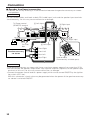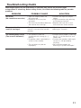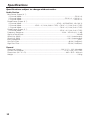
1
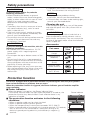
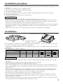
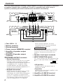
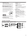
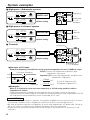
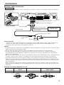
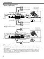
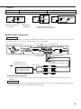
KAC-648
4-CHANNEL POWER AMPLIFIER
INSTRUCTION MANUAL
B64-1364-00 (EM)
Safety precautions
2WARNING
To prevent injury and/or fire, take the
following precautions:
• When extending the battery or ground
cables, make sure to use automotive-grade
cables or other cables with an area of 3 mm 2
(AWG12) or more to prevent cable
deterioration and damage to the cable
coating.
• To prevent short circuits, never put or leave
any metallic objects (e.g., coins or metal
tools) inside the unit.
• If the unit starts to emit smoke or strange
smells, turn off the power immediately and
consult your Kenwood dealer.
• Do not touch the unit during use because the
surface of the unit becomes hot and may
cause burns if touched.
2CAUTION
To prevent damage to the machine, take the
following precautions:
• Be sure the unit is connected to a 12V DC
power supply with a negative ground
connection.
• Do not open the top or bottom covers of the
unit.
• Do not install the unit in a spot exposed to
direct sunlight or excessive heat or humidity.
Also avoid places with too much dust or the
possibility of water splashing.
• When replacing a fuse, only use a new one
with the prescribed rating. Using a fuse with
the wrong rating may cause your unit to
malfunction.
• To prevent short circuits when replacing a
fuse, first disconnect the wiring harness.
NOTE
• If you experience problems during
installation, consult your Kenwood dealer.
• If the unit does not seem to be working right,
consult your Kenwood dealer.
Cleaning the unit
If the front panel gets dirty, turn off the power
and wipe the panel with a dry silicon cloth or
soft cloth.
2CAUTION
Do not wipe the panel with a hard cloth or a
cloth dampened by volatile solvents such as
paint thinner and alcohol. They can scratch the
surface of the panel and/or cause the indicator
letters to peel off.
Accessories
Part name
External
View
Number of
Items
Round terminal
(Large)
1
Round terminal
(Medium)
2
Round terminal
(Small)
1
Terminal cover
(Power terminal)
1
Self-tapping screws
(ø4 × 16 mm)
4
Protection function
This unit is equipped with a protection function for protecting this unit and your speakers
from various accidents or problems that can occur.
When the protection function is triggered, the Power indicator goes off and the amplifier
stops operating.
■ Power indicator:
When the power is turned on, the Power indicator lights.
If the Power indicator does not light when the power is turned on, the
protection function may be activated. Check whether there is any
indication of trouble.
■ The protection function activates in the following
situations:
• When a speaker cable may be short-circuited.
• When a speaker output contacts ground.
• When the temperature of internal parts exceeds 120°C (248°F).
• When a ground cable of the center unit (cassette receiver, CD receiver,
etc.) or this unit is not connected to a metal part serving as an
electrical ground passing electricity to the battery's negative terminal.
2
Power indicator
Installation procedure
1. Remove the ignition key and disconnect the negative - terminal of the battery to prevent short
circuits.
2. Set the unit according to the intended usage.
3. Connect the input and output cables of the units.
4. Connect the speaker cables.
5. Connect the power cable, power control cable and grounding cable following this order.
6. Install the unit in the car.
7. Connect the negative - terminal of the battery.
2CAUTION
• Be sure to turn the power off before changing the setting of any switch.
• If the fuse blows, check cables for shorts, then replace the fuse with one of the same rating.
• Check that no unconnected cables or connectors are touching the car body. Do not remove
caps from unconnected cables or connectors to prevent short circuits.
• Connect the speaker cables to appropriate speaker connectors separately. Sharing the negative
cable of the speaker or grounding speaker cables to the metal body of the car can cause this
unit to fail.
• After installation, check that the brake lamps, winkers, and wipers work properly.
Installation
Self-tapping screw
Installation board, etc.
(thickness : 15 mm or more)
,,,,,,,,,,,,,,,,,,
,,,,,,,,,,,,,,,,,,
,,,,,,,,,,,,,,,,,,
,,,,,,,,,,,,,,,,,,
,,,,,,,,,,,,,,,,,,
,,,,,,,,,,,,,,,,,,
,,,,,,,,,,,,,,,,,,
,,,,,,,,,,,,,,,,,,
,,,,,,,,,,,,,,,,,,,,,,,,,,,,,,,,,,,,,,,,,,,,
,,,,,,,,,,,,,,,,,,,,,,,,,,,,,,,,,,,,,,,,,,,,
,,,,,,,,,,,,,,,,,,,,,,,,,,,,,,,,,,,,,,,,,,,,
,,,,,,,,,,,,,,,,,,,,,,,,,,,,,,,,,,,,,,,,,,,,
,,,,,,,,,,,,,,,,,,,,,,,,,,,,,,,,,,,,,,,,,,,,
,,,,,,,,,,,,,,,,,,,,,,,,,,,,,,,,,,,,,,,,,,,,
,,,,,,,,,,,,,,,,,,,,,,,,,,,,,,,,,,,,,,,,,,,,
,,,,,,,,,,,,,,,,,,,,,,,,,,,,,,,,,,,,,,,,,,,,
,,,,,,,,,,,,,,,,,,
• Since the power amplifier has no parts which require operation, it can be installed at a position
away from the driver’s seat without any hindrances.
As generally accepted positions for its installation, places such as inside the trunk, etc. can be
considered.
• Use the extension cables. (Optional.)
Length
0.5m
1m
2m
4m
5m
6m
Type
RCA cable
CA-2SL
CA-12SL CA-22SL
CA-52SL
RCA cable (ø7mm)
CA-3WL CA-13WL CA-23WL
CA-53WL
RCA cable (ø12mm)
CA-5W
CA-15W
CA-25W
CA-45W
CA-65W
2CAUTION
• Do not install the unit under the carpet. Otherwise heat build-up occurs and the unit may be
damaged.
• Install this unit in a location which allows heat to easily dissipate.
Once installed, do not place any object on top of the unit.
• The surface temperature of the amplifier will become hot during use. Install the amplifier in a
place where people, resins, and other substances that are sensitive to heat will not come into
contact with it.
• When making a hole under a seat, inside the trunk, or somewhere else in the vehicle, check
that there is nothing hazardous on the opposite side such as a gasoline tank, brake pipe, or
wiring harness, and be careful not to cause scratches or other damage.
• Do not install near the dashboard, rear tray, or air bag safety parts.
• The installation to the vehicle should securely fasten the unit to a place in which it will not
obstruct driving. If the unit comes off due to a shock and hits a person or safety part, it may
cause injury or an accident.
• After installing the unit, check to make sure that electrical equipment such as the brake lamps,
turn signal lamps and windshield wipers operate normally.
3
Controls
This is a 4 channel amplifier including 2 stereo amplifiers in a body. One amplifier is referred to
as amplifier A and the other is amplifier B. This unit is compatible with a large variety of
systems by combining the switches and functions described in the following.
5
POWER IN
FUSE(25A)
SPEAKER OUTPUT
GND
SPEAKER LEVEL INPUT
LEFT
RIGHT
BRIDGED
LEFT
RIGHT
A
A
P.CON(REMOTE)
BATT
SPEAKER LEVEL INPUT
A
25
B
B
L
B
1
2 34
6
FILTER
INPUT SELECTOR
A B
A
OPERATION
MONO(Lch)
7
9 0 !
8
OFF
STEREO
HPF
LPF
LINE IN
A
B
OPERATION
LINE OUT
A + B
STEREO
0.5
MONO L
L
FILTER
OFF
HPF
LPF
0.5
GND
0.3
0.3
MIN
MAX
INPUT
SENSITIVITY(V)
R
R
CONTROL A
mA
(Lch)
MONO
1.0
1.0
MIN
R
MAX
INPUT
SENSITIVITY(V)
4 CHANNEL
POWER AMPLIFIER
CONTROL B
@
mA
#
$
%
1 Fuse (25 A × 1)
2 Battery terminal
3 Ground terminal
4 Power control (REMOTE) terminal
5 Amplifier A speaker output
terminals
6 Amplifier B speaker output
terminals
❖ SPEAKER OUTPUT terminals
• Stereo Connections:
When you wish to use the unit as a stereo
amplifier, stereo connections are used.
The speakers to be connected should have
an impedance of 2Ω or greater. When
multiple speakers are to be connected,
ensure that the combined impedance is 2Ω
or greater for each channel.
• Bridged Connections:
When you wish to use the unit as a highoutput monaural amplifier, bridged
connections are used. (Make connections
to the LEFT channel (+) and the RIGHT
channel (–) SPEAKER OUTPUT terminals.)
The speakers to be connected should
have an impedance of 4Ω or greater.
4
When multiple speakers are to be
connected, ensure that the combined
impedance is 4Ω or greater.
2CAUTION
The rated input of the speakers should be
no less than the maximum output of the
amplifier. Otherwise malfunction may
result.
7 Speaker level input terminals
8 INPUT SELECTOR switch
This switch selects the input method of the
signals to be amplified by amplifiers A and
B.
A B
A
INPUT SELECTOR
• A B position:
Amplifies both of the signals input to
amplifiers A and B.
• A position:
Amplifies only signal input amplifier A with
both amplifiers A and B.
9 Amplifier A LINE IN terminal
0 Amplifier B LINE IN terminal
independently according to the setting of
this switch.
! LINE OUT terminal
These jacks output respectively the signals
input to amplifiers A and B. They always
output the stereo signals regardless of the
position of the OPERATION switch.
• STEREO position:
The amplifier can be used as a stereo
amplifier.
• MONO (Lch) position:
@ RCA cable ground lead terminal
# INPUT SENSITIVITY control
Set this control according to the pre-output
level of the center unit connected with this
unit, or to the maximum power output of
the genuine-accessory car stereo.
The sensitivities of amplifiers A and B can
be adjusted independently regardless of the
position of the input selector switch.
Use the diagram on
15
10
1.0
the right as a guide.
Amplifies the signal input from the left side
only. Set to this position and make bridged
connections to use as a high-power
monaural amplifier. (The input right signal is
not output.)
% FILTER switch
1.0
0.5
2.0
0.3
3.0
25
MIN
4.0 (V)
NOTE
MAX
0.5
0.3
0.2
(W)
For the pre-output level or the maximum
power output, refer to the “Specifications”
in the instruction manual of the center unit.
$ OPERATION switch
These switches allow filtering of the
speaker output signals.
• HPF(High Pass Filter) position:
Only frequencies of 150Hz or higher are
output. (Frequencies below 150Hz are cut.)
• LPF(Low Pass Filter) position:
Only frequencies of 80Hz or lower are
output. (Frequencies above 80Hz are cut.)
The Lch and Rch will be mixed before
output even if the operation switch is set to
STEREO.
• OFF position:
The original sound without filtering is
output.
The amplification methods of the signals
input to amplifiers A and B can be selected
System examples
■ Full-range 4-channel + Subwoofer system
L
1.0
FILTER
0.5
OPERATION
OFF
STEREO
HPF
LPF
0.3
MIN
INPUT SELECTOR
A B
A
CONTROL B
OFF
HPF
LPF
MAX
INPUT
SENSITIVITY(V)
CONTROL A
FILTER
R
MONO(Lch)
CENTER UNIT
STEREO
L
R
L
B
L
L LINE
R OUT
R
R
1.0
OPERATION
A
0.5
(Lch)
MONO
0.3
MIN
MAX
INPUT
SENSITIVITY(V)
Switch setting
L
R
Front
speaker
Rear
speaker
Subwoofer
Power amplifier
5
System examples
■ High-pass + Subwoofer system
1.0
MONO(Lch)
0.3
MIN
INPUT SELECTOR
A B
A
MAX
INPUT
SENSITIVITY(V)
CONTROL A
CONTROL B
R
CENTER UNIT
OPERATION
L
STEREO
R
0.5
(Lch)
MONO
0.3
MIN
MAX
A
L
(High pass)
R
1.0
FILTER
OFF
HPF
LPF
L
0.5
OPERATION
Switch setting
B
L LINE
R OUT
INPUT
SENSITIVITY(V)
BRIDGED
FILTER
OFF
STEREO
HPF
LPF
Subwoofer
(L + R)
(Bridged)
0.5
OPERATION
MONO(Lch)
0.3
MIN
INPUT SELECTOR
A B
A
INPUT
SENSITIVITY(V)
CONTROL A
CONTROL B
R
1.0
FILTER
OFF
HPF
LPF
MAX
OPERATION
STEREO
0.5
(Lch)
MONO
0.3
MIN
MAX
INPUT
SENSITIVITY(V)
Switch setting
■ Tri-mode
L
R
CENTER UNIT
L
R
A
B
L LINE
R OUT
BRIDGED
L
1.0
FILTER
OFF
STEREO
HPF
LPF
Left
speaker
BRIDGED
■ High-power 2-channel system
Right
speaker
(High pass)
1.0
FILTER
0.5
OPERATION
OFF
STEREO
HPF
LPF
0.3
MIN
INPUT SELECTOR
A B
A
MAX
CONTROL A
INPUT
SENSITIVITY(V)
CONTROL B
1.0
FILTER
OFF
HPF
LPF
OPERATION
STEREO
L
MONO(Lch)
CENTER UNIT
L
R
0.5
(Lch)
MONO
0.3
MIN
R
MAX
Switch setting
INPUT
SENSITIVITY(V)
A
C
L
C
L
L
R
B
L
L LINE
R OUT
R
Subwoofer
(L + R) (Bridged)
●Principle of Tri-mode
Method of frequency band division using a coil and capacitor•••in case of 6dB/oct. slope
Crossover Frequency
0 dB
-3 dB
L
C
Frequency
Coil (L): Passes low frequencies and blocks high
frequencies. (Low pass)
Capacitor (C): Passes high frequencies and blocks low
frequencies. (High pass)
159000
C=
(µF)
fc=Cut of Frequency (Hz)
fc x R
R=Speaker Impedance (Ω)
159 x R
L=
(mH)
fc
●Example:
When it is required to set a crossover frequency of 120 Hz using speakers with an
impedance of 4 ohms.
Prepare commercially-available coil and capacitor with the closest ratings to the results
calculated from the formula above. The capacitor rating should be as close as possible to 331.25
(µF) and the coil rating should be as close as possible to 5.3 (mH).
2CAUTION
• If you wish to bridge-connect a speaker, the speaker impedance must be no less than 4 ohms.
Connecting a speaker with an impedance lower than 4 ohms may damage the unit.
• Be sure to connect capacitors to speakers to which high frequencies will be passed. Failure to
do so will result in a drop of the combined impedance with the subwoofer.
• Ensure that the withstand voltage and current ratings of the capacitors (C) and coils (L) are
sufficient.
6
Connection
■ Power cable connection
2WARNING
To prevent fire caused by a short in the wiring, connect a fusible link or breaker nearby the battery’s
positive terminal.
POWER IN
FUSE(25A)
SPEAKER OUTPUT
GND
BATT
BRIDGED
LEFT
RIGHT
SPEAKER LEVEL INPUT
LEFT
RIGHT
A
A
P.CON(REMOTE)
SPEAKER LEVEL INPUT
A
25
B
B
B
L
R
Round terminal (Small)
Round terminal (Medium)
Power terminal
Terminal cover
Power control cable
CENTER UNIT
Battery cable
Ground cable
Round terminal (Large)
Protective
Fuse
Battery
Power terminal
Connect to their respective terminals the power control cable, power supply cable, and ground
cable, all of which pass through the associated terminal cover. Once the connections are
complete, place the cover on the terminal section.
Wiring
• If a buzzing noise is heard from the speakers when the engine is running, connect a line noise filter
(optional) to each of the battery cable.
• Do not allow the cord to directly contact the edge of the iron plate by using Grommets.
• Connect the ground cable to a metal part of the car chassis that acts as an electrical ground
passing electricity to the battery‘s negative - terminal. Do not turn the power on if the ground
cable is not connected.
• Be sure to attach a protective fuse into the battery cable close to the battery. Use a protective fuse
having a capacity that is about 10 A higher than the maximum current drawn by the amplifier.
• Use vehicle-type (fire-resistant) power supply wiring cable for the battery cable and the ground
cable. The current capacity of the power supply wiring cable should be about 10 A higher than that
of the protective fuse capacity (which means about 20 A higher than the maximum current drawn
by the amplifier).
• When more than one power amplifier are going to be used, use a power supply wiring cable and
protective fuse of greater current-handling capacity than the total maximum current drawn by each
amplifier.
Example: One Power Amplifier Is Used
Model
Maximum Current
Protective Fuse
Cross-sectional Area of Wiring
Drawn
Cable (AWG)
KAC-648
22 A
30 A × 1 [15 A × 2]
3 mm2 (AWG 12) or greater × 1
15 A
30 A
15 A
15 A
15 A
7
Connection
■ Speakers cable connection
(Stereo Connections)
Front Left speaker
Lead terminal
(Commercially
available parts)
Front Right speaker
ED
IDG
BR
A Right output
A Left output
POWER IN
FUSE(25A)
SPEAKER OUTPUT
GND
BATT
BRIDGED
LEFT
RIGHT
LE
RIG
HT
FT
SPEAKER LEVEL INPUT
LEFT
RIGHT
A
A
P.CON(REMOTE)
SPEAKER LEVEL INPUT
A
25
B
B
L
B
R
Speaker terminal polarity
BRIDGED
B Right output
B Left output
A
B
L
R
Rear Right speaker
Rear Left speaker
(Bridged Connections)
Lead terminal
(Commercially
available parts)
Speaker (Bridged)
ED
IDG
BR
A Bridged output
POWER IN
FUSE(25A)
SPEAKER OUTPUT
GND
BATT
A
P.CON(REMOTE)
BRIDGED
LEFT
RIGHT
LE
RIG
HT
FT
SPEAKER LEVEL INPUT
LEFT
RIGHT
A
SPEAKER LEVEL INPUT
A
25
B
B
B
L
R
Speaker terminal polarity
BRIDGED
B Bridged output
A
B
L
R
Speaker (Bridged)
■ Speaker Selection
• The rated input power of the speakers that are going to be connected should be greater than
the maximum output power (in Watts) of the amplifier. Use of speakers having input power
ratings that are less than the output power of the amplifier will cause smoke to be emitted as
well as damage.
• The impedance of the speakers that are going to be connected should be 2Ω or greater (for
stereo connections), or 4Ω or greater (for bridged connections). When more than one set of
speakers are going to be used, calculate the combined impedance of the speakers and then
connect suitable speakers to the amplifier.
8
Examples:
Stereo Connections (4Ω)
50 W or greater
Model
KAC-648
50W
(4Ω)
50W
(4Ω)
50W
(2Ω)
50W
(4Ω)
25W
(8Ω)
50W
(4Ω)
50W
(2Ω)
4Ω
Maximum output of
the amplifier
Bridged Connections (4Ω)
140 W or greater
4Ω
4Ω
Combined
impedance
25W
(8Ω)
Rated input power and
impedance of the speakers
■ RCA cable connection
2CAUTION
Do not connect cables and leads to both RCA cable input jacks and the speaker input terminals
simultaneously, for this may cause malfunction or damage.
D
GN
B Left input
A Left input
RCA cable ground terminal
FILTER
INPUT SELECTOR
A B
A
OPERATION
OFF
STEREO
HPF
LPF
MONO(Lch)
LINE IN
A
B
OPERATION
LINE OUT
A + B
STEREO
0.5
MONO L
L
R
R
GND
0.3
MIN
MAX
INPUT
SENSITIVITY(V)
CONTROL A
A Right input
To Power control
(REMOTE) terminal
FILTER
OFF
HPF
LPF
0.5
0.3
MIN
(Lch)
MONO
1.0
1.0
MAX
INPUT
SENSITIVITY(V)
4 CHANNEL
POWER AMPLIFIER
CONTROL B
B Right input
RCA cable
(Commercially available part)
Front output
CENTER UNIT
(Cassette receiver,
CD receiver, etc.)
Rear output
RCA cable ground terminal
When using an RCA cable with a ground lead attached, connect the ground lead to this
terminal.
2CAUTION
Do not use this terminal for power source grounding. This unit will be damaged if the power
source grounding wire is connected to this terminal.
9
Connection
■ Speaker level input connection
Connect the unit by inserting it in the connection between the genuine-accessory car stereo
and speakers.
2CAUTION
Do not connect cables and leads to both RCA cable input jacks and the speaker input terminals
simultaneously, for this may cause malfunction or damage.
To Power control
(REMOTE) terminal
A Left input
POWER IN
FUSE(25A)
SPEAKER OUTPUT
GND
BATT
A Right input
BRIDGED
LEFT
RIGHT
SPEAKER LEVEL INPUT
LEFT
RIGHT
A
A
P.CON(REMOTE)
SPEAKER LEVEL INPUT
A
25
B
B
B
L
ACC
Battery
Car fuse
box
R
B Right input
B Left input
ER
K
EAT
SP LEF
T
PU
IN
L IGHT
VE R
LE
Front Right
Genuine-accessory
car stereo
Front Left
Rear Left
Rear Right
Lead terminal
(Commercially available parts)
2CAUTION
• The genuine-accessory car stereo shall have a maximum power output of no more than 25 W.
• Do not connect the speaker output leads from a power amplifier (Optional) to the speaker input
terminals of this unit, for this may cause malfunction or damage.
• Connect the power control lead to a power supply which can be turned ON/OFF by the ignition
key switch (ACC line).
With this connection, shock noise may be generated when the power of the genuine-accessory
car stereo is switched ON/OFF.
10
Troubleshooting Guide
What might appear to be a malfunction in your unit may just be the result of slight
misoperation or miswiring. Before calling service, first check the following table for possible
problems.
PROBLEM
POSSIBLE CAUSE
SOLUTION
No sound.
(No sound from one side.)
• Input (or output) cables are
• Connect the input (or output)
disconnected.
cables.
• Protection circuit may be
• Check connections by referring
activated.
to "Protection function".
• The fuse may be blown because • Replace the fuse with a new
the volume was too high.
fuse and use a lower volume.
The output level is too
small (or too large).
The input sensitivity adjusting
control is not set to the correct
position.
Adjust the control correctly
referring to “Controls”.
The sound quality is bad.
(The sound is distorted.)
• The speakers cable are
connected with wrong + / polarity.
• A speaker cable is pinched by a
screw in the car body.
• Connect them properly checking
the + / - of the terminals and
cables well.
• Connect the speaker cable again
so that it is not pinched by
anything.
• Set switches properly by
referring to "System examples".
• The switches may be set
improperly.
11
Specifications
Specifications subject to change without notice.
Audio Section
Max Power Output (4 Ω)
4 Channel Mode.................................................................................................................50 W × 4
3 Channel Mode ............................................................................................50 W × 2 + 140 W × 1
2 Channel Mode...............................................................................................................140 W × 2
Rated Power Output (4 Ω)
4 Channel Mode ..........................................................................25 W × 4 (DIN45324, +B=14.4 V)
3 Channel Mode ............................25 W × 2 (1 kHz, 0.08 % THD) + 70 W × 1 (1 kHz, 0.8 % THD)
2 Channel Mode .................................................................................70 W × 2 (1 kHz, 0.8 % THD)
Rated Power Output (2 Ω)
4 Channel Mode .................................................................................35 W × 4 (1 kHz, 0.8 % THD)
Frequency Response ...............................................................................10 Hz ~ 45 kHz (+0, –1 dB)
Signal to Noise Ratio................................................................................................................100 dB
Sensitivity (MAX) .................................................................................................0.2 V (rated output)
Sensitivity (MIN) ..................................................................................................4.0 V (rated output)
Input Impedance........................................................................................................................10 kΩ
Low Pass Filter .......................................................................................................80 Hz (12 dB/oct.)
High Pass Filter.....................................................................................................150 Hz (12 dB/oct.)
General
Operating Voltage...................................................................................14.4 V (11 ~ 16 V allowable)
Current Consumption ....................................................................................22 A (1 kHz, 10% THD)
Dimensions (W × H × D) ...................................................................................260 × 56.5 × 209 mm
Weight .......................................................................................................................................3.0 kg
12