1
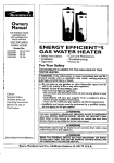
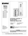
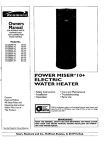
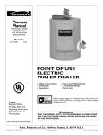
Owners
Manual
FOR POTABLE WATER
HEATING ONLY
NOT SUITABLE FOR
SPACEHEATING
Model
153.327164
153.327264
153.327363
153.327364
153.327463
153.327464
153.327563
153.327564
153.327663
153.327664
153.327863
153.327864
No.
30 GaL Short
40 Gal. Short
30 Gal.
30 Gal.
40 Gal.
40 Gal.
50 Gal.
50 Gal.
66 Gal.
66 Gal.
82 Gal.
82 Gal.
POWER
ELECTRIC
WATER
• Safety Instructions
• Installation
• Operation
MISER
TM
9+
HEATER
• Care and Maintenance
• Troubleshooting
• Parts List
Caution:
Read and Follow
All Safety Rules and
Operating Instructions
Before First Use of
This Product.
GAMA certification applies to a_lresidential electric water heaters with
capacities of 20 to 120Gallons. Input rating of 12 Kw or lessat a voltage
no greater than 250 V.
I
Save this Manual for Future Reference.
Sears,
Roebuck
_kWARNING
READ THE GENERAL SAFETY SECTION
BEGINNING
ON
AND THEN THIS ENTIRE MANUAL
BEFORE INSTALLING
ING THIS WATER HEATER.
and Co., Hoffman
Estates,
IL 60179
U.S.A.
INSIDE COVER
OR OPERAT-
Safety Precautions
AWARNING
I
improper installation, adjustment, alteration, service or
maintenancecan causeDEATH, SERIOUS BODILY INJUR_,I
OR PROPERTY DAMAGE. Refer to this manual for assistance or consultyour local SearsService Center for further
nformation.
AWARNING
At the time of manufacturethiswater heaterwasprovidedwith
a combinationtemperature-pressures
relief valvecertifiedby a
nationallyrecognizedtesting laboratorythat maintainsperiodic
inspectionof productionof listedequipmentor materials, as
meeting the requirementsfor ReliefValvesand AutomaticGas
Shutoff Devicesfor Hot Water SupplySystems,and the latest
edition of ANSI Z21.22 and the code requirements of ASME. If
replaced,the valvemust meet the requirementsof localcodes,
but not lessthan a combinationtemperatureand pressurerelief
valvecertifiedasmeetingthe requirements for RelinfValvesand
AutomaticGasShutoffDevicesfor Hot Water SupplySystems,
ANSI Z21.22 by a nationally recognizedtesting laboratorythat
maintains periodic inspectionof productionof listedequipment
or materials.
The valvemust be marked with a maximum set pressurenot
to exceed the marked hydrostaticworking pressureof the
water heater (150 Ibs./sq.in.) and a dischargecapacity not
lessthan the water heater input rate as shownon the model
rating plate. (Electric heaters - watts dividedby 1000 x 3415
equal BTU/Hr. rate.)
Yourlocaljurisdictional
authority,whilemandatingthe useof a
temperature-pressure reliefvalvecomplyingwith ANSI Z21.22
and ASME,mayrequire a valvemodeldifferentfrom the onefurnlsfiedwiththe water h0_ter.
Compliancewith suchlocal requirements must be satisfiedby
the installeror end userof the water heater with a locallyprei scribedtemperature-pressure
relief valveinstalledin the designated openingin the water heater in placeof the factory furnisfiedvalve.
For safeoperationofthe water heater,the relief valvemustno
be removedfrom it'sdesignated
openingor plugged.
The temperature-pressurerelief valvemustbe installeddirectly
intothe fittingof the water heaterdesignated
for the relief valve.
Positionthe valvedownwardand providetubing sothat any dischargewill exit onlywithin 6 inchesabove,or at any distance
belowthe structuralfloor.Be certain that no contactis made
with anylive electricalpart. The discharge
openingmust not be
blockedor reduced in size under anycircumstances.
Excessive
length,over 30 feet,or useof more than four elbowscancause
restrictionand reducethedischarge
capacityof the valve.
No valveor otherobstructionisto be placedbetween the relief
valveandthe tank. Do not connecttubing directlyto discharge
drainunlessa 6" air gapisprovided.To preventbodilyinjury,hazard to life,or propertydamage,the reliefvalvemustbe allowed
to discharge
water in quantitiesshouldcircumstances
demand.If
the dischargepipeis not connectedto a drainor other suitable
means, the
water
flow may cause property
damage.
The DischargePipe:
Must not be smaller in size than the outlet pipe size of
the valve, or have any reducing couplings or other
restrictions
Must not be pluggedor blocked.
Must be of material listedfor hot water distribution.
Must be installed so as to allow complete drainage of
both the temperature-pressure relief valve, and the
dischargepipe.
Must terminate at an adequatedrain.
Must not haveanyvalvebetween the relief valveand tank.
I
AWARNING
_]
HAZARD OF ELECTRICAL SHOCK! Before removing I
any access panels or servicing the water heater, make I
sure the electrical supply to the water heater is turned I
"OFF". Failure to do this could result in DEATH, SERIOUS BODILY INJURY,OR PROPERTY DAMAGE. J
_,WARNING
HOTTER WATER CAN SCALD: Water heaters are
intended to produce hot water. Water heated to a temperature which will satisfyspaceheating, clothes washing,
dish washing, and other sanitizing needs can scald and
_ermanently injure you upon contact. Some people are
more likely to be permanently injured by hot water than
others. These include the elderly, children, the infirm, or
physically/mentally handicapped. If anyone using hot
water in your home fits into one of these groups or if
there is a local code or state law requiring a certain tem.
_erature water at the hot water tap, then you must take
special precautions. In addition to using the lowest possible temperature setting that satisfies your hot water
needs, a means such as a mixing valve, shall be used at
the hot water taps used by these people or at the water
heater. Mixing valves are available at plumbing supply or
hardware stores. Follow manufacturers instructions for
installation of the valves. Before changingthe factory setting on the thermostat,
read the "Temperature
Regularon" sect on n this manua.
_,WARNING
WATER HEATERS EQUIPPED FOR ONE VOLTAGE
ONLY: This water heater is equipped for one type voltage
only. Check the rating plate near the bottom accesspanel
for the correct voltage. DO NOT use this water heater
with any voltage other than the one shownon the model
rating plate. Failure to use the correct volta..gecan cause
problems which ca'T_r_s'0Rin-"DE'_, _'_RIOUS BODILY
INJURY, OR PROP_ERT.Y_D_JLFou
have any questions or doubts consult your electric company.
• ,WARNIJEIG-
,- '
INSULATING JACKETS: When installing anexternal
water heater ins_ff'T_'e_ctric
water
heater:
a. DO NOT cover the temperature-pressure relief valve;
b. DO NOT put inr_at_n._J_leeess_covers_or
any
access
areas.
c. DO NOT cover or remove operating instructions, and
safety related warning labels and materials affixed to the
water heater.
I
AWARNING
Do not use this appliance if any part of it hasbeen under
water. An electrical short or malfunction could occur.The
water heater shouldbe replaced.
A CAUTION
WATER HEATERS EVENTUALLY LEAK: Installation of
the water heater must be accomplishedin such a manner
that if the tank or any connectionsshouldleak, the flow of
water will not causedamage to the structure. When such
locations cannot be avoided, a suitable drain pan should
be installed under the water heater. Drain pans are available at your local Sears Store. Such a drain pan must be
piped to an adequate drain. Under no circumstances is
the manufacturer or Sears to be held liable for any water
damage in connection with this water heater.
Table of Contents
Safety Precautions .......................................................................................................
2
Table of Contents ........................................................................................................
3
Introduction ........................................................................................................................
4
Product Specifications ......................................................................................................
4
Preparing for the New Installation ..........................................................................
4
Materials and Basic Tools Needed ...........................................................................
5
Materials Needed ......................................................................................................................................................................
Basic Tools ................................................................................................................................................................................
Installation
Instructions
5
5
...................................................................................................
6-15
Removing the Old Water Heater ...............................................................................................................................................
Facts to Consider About the Location .......................................................................................................................................
Facts to Consider About the Convertible Hement ....................................................................................................................
Water Piping .............................................................................................................................................................................
Temperature-Pressure Relief Valve.............................................................................................................................................
Filling the Water Heater ..........................................................................................................................................................
Converting the Lower Element ..........................................................................................................................................
Wiring Diagrams ....................................................................................................................................................................
Wiring ....................................................................................................................................................................................
Installation Checldist ..............................................................................................................................................................
6
7
7
8
9
10
10-12
13
14
15
Service and Adjustment .............................................................................................
16-20
Temperature Regulation ..........................................................................................................................................................
Thermostats ............................................................................................................................................................................
Thermostat Settings ................................................................................................................................................................
Upper Thermostat Adjustment ...............................................................................................................................................
Lower Thermostat Adjustment ...............................................................................................................................................
Temperature-Pressure Relief Valve Operation ..........................................................................................................................
Draining .................................................................................................................................................................................
Element Cleaning and Replacement ..................................................................................................................................
Drain Valve Washer Replacement ...........................................................................................................................................
Service ....................................................................................................................................................................................
Troubleshooting
16
16
16
16
!7
17
17
18-20
20
20
Guide .............................................................................................
21-24
Start Up Conditions ...............................................................................................................................................................
Thermal Expansion ...............................................................................................................................................................
Strange Sounds .....................................................................................................................................................................
Operational Conditions ..........................................................................................................................................................
Rumbling Noise ....................................................................................................................................................................
High Temperature Shut Off System ......................................................................................................................................
Not Enough or No Hot Water ..............................................................................................................................................
Water is Too Hot ..................................................................................................................................................................
21
21
21
22
22
22
22
22
Leakage Checkpoints ..............................................................................................................................................................
23
Parts Order List ..................................................................................................................
24-27
Warranty
......................................................................................................................................
28
Introduction
Thank You for
Abbreviations
Found In This Instruction
Manual
U.L.-Underwriters
Laboratories,
333 Pfingsten
Rd.,
Northbrook, IL 60062
National Electrical Code-This publication is available from your
local government or public library or electric company or by
writing to U.L. above.
A.N.S.I.-American National Standards Institute
purchasing a Sears water heater.
Properly installed and maintained, it should give you years of
trouble free service. If you should decide that you want the new
water heater professionally installed, contact the local Sears
Service Center or any Sears store. They will arrange for prompt,
quality installation by Sears authorized contractors.
Product
MODEL
NUMBER
Specifications
TANK
RECOVERY RATE
CAPACITY DIMENSIONS IN INCHES GALS. PER HOUR
IN GALLONS DIAMETER
HEIGHT
CagO°ERISE
153.327164
30
2Y'
30"
153.327264
40
25"
32W'
153.327363
153.327364
30
19"
45_"
153.327463
153.327464
40
19"
59¾"
153.327563
153.327564
50
21"
57
153.327663
153.327664
66
23"
60¼"
153.327863
153.327864
82
25"
60¼"
17.3
25.0
17.3
25.0
17.3
25.0
17.3
25.0
17.3
25.0
17.3
25.0
17.3
25.0
ELEMENT
WATTAGE
AT240 VOLTS
UPPER LOWER
3800
3800
3800
3800
3800
3800
3800
3800
3800
3800
3800
5500
3800
5500
3800
5500
3800
5500
3800
5500
3800
5500
3800
5500
MINIMUM
WIRE SIZE*
MAXIMUM FUSE
OR CIRCUIT
BREAKER
(GAUGE)
SIZE (AMPS)
12
10
12
10
12
10
12
10
12
10
12
10
12
10
2O
30
20
30
20
3o
20
30
2O
30
20
30
20
30
*Wiring size based on standard 60°C copper wire. If distance from fuse box to water heater is more than 90 feet, refer to your local electrical code.
Preparing for the New Installation
• Read the "Safety Precautions" section, page 2 of this manual
first and then the entire manual carefully. If you don't follow
the safety rules, the water heater will not operate properly. It
could cause DEATH, SERIOUS
BODILY INJURY
AND/OR PROPERTY DAMAGE.
This manual contains instructions for the installation, operation, and maintenance of this electric water heater. It also
contains warnings throughout the manual that you must read
and be aware of. All warnings and all instructions are essential
to the proper operation of the water heater and your safety.
Since we cannot put everything on the first few pages, READ
THIS ENTIRE MANUAL BEFORE ATTEMPTING TO
INSTALL OR OPERATE THE WATER HEATER.
• The installation must conform with the instructions in this
manual; electric company rules; and Local Codes, or in the
absence of Local Codes, with the latest edition of the
National Electrical Code. This publication is available from
your local government or public library or electric company
or by writing Underwriters Laboratories, 333 Pfingsten Road,
Northbrook, IL 60062.
•
If after reading this manual you have any questions or do not
understand any portion of the instructions, call Sears Service
Center.
• Carefully plan the place where you are going to put the water
heater. Correct electrical wiring and connections
are very
important in preventing death from possible electrical shock
and fires.
Examine the location to ensure the water heater complies
with the "Facts to Consider About the Location" section.
For California installation this water heater must be braced,
anchored, or strapped to avoid falling or moving during an
earthquake.
See instructions
for correct installation
procedures. Instructions
may be obtained
from the California
offlcc of the State Architect, 400 P Street, Sacramento,
CA
95814
Materials
and Basic Tools Needed
Materials Needed
To simplify the installation Sears has available the installation
parts shown below. You may or may not need all of these materials, depending on your type of installation.
O
J
j E_-tr_
I Water Heater
i tesMIlatlon
20" DIAMETER DRAIN PAN
FOR WATER HEATERS 18" IN
DIAMETER AND UNDER
WATER HEATER HEAT TRAPS
HELP REDUCE HEAT LOSS DUE
TO THERMAL SYPHONING
_b
.......
_
EXPANSION
TANKS FOR THERMAL
EXPANSION
CONDITIONS
AVAILABLE
IN 2 GALLON AND 5 GALLON CAPACITY
THROUGH
LOCAL SEARS SERVICE
CENTERS
WATER HEATER INSTALLATION KIT WITH FLEXIBLE
CONNECTORS
FOR 314" OR
I12" THREADED
OR COPPER
PLUMBING
28" DIAMETER DRAIN PAN FOR
WATER HEATERS 26" IN
DIAMETER AND UNDER
Basic Tools
You may or may not need all of these tools, depending on your
type of installation. These tools can be purchased at your local
Sears store.
Pipe Wrench (2)
Screwdriver
6 Foot Tape or Folding Rule
Garden Hose
Drill
Pipe Dope or Teflon Tape
ADDITIONAL
TOOLS NEEDED
WHEN
SWEAT SOLDERING
Tubing Cutters or Hacksaw
Propane Torch
Soft Solder
Solder Flux
Emery Cloth
Wire
Brushes
6 FOOT TAPE
GARDEN
HOSE
314" WIRE BRUSH
SLOT-HEAD
PHILLIPS
r 7
SCREW
DRIVER
PIPE
WRENCH
112"WIRE BRUSH
SCREWDRIVER
PROPANE TORCH
ROLL OF LEAD FREE
SOFT SOLDER
PIPE DOPE
(SQUEEZE
TUBE)
ROLL OF TEFLON
(Use
only on water
TAPE
connections)
DRILL
ROLL OF EMERY
CLOTH
SOLDER
FLUX
TUBING
CUTTER
Installation
Instructions
Removing the Old Water
Heater
QTurn
a.
"OFF" electrical supply to the water heater.
If you have copper piping to the water
heater, the two copper water pipes can be
cut with a hacksaw approximately 4" away
from where they connect
to the water
heater. This will avoid cutting off the pipes
too short. Additional
cuts can be made
later if necessary. Disconnect the temperature-pressure relief valve drain line. When
the water heater is drained, disconnect the
hose from the drain valve. Close the drain
valve. The water heater is now completely
disconnected and ready to be removed.
©
Q
Turn "OFF" the water supply to the
water heater at the water shutoffvalve
or
water meter.
Qb.
QAttach
valve
drain
drain
faucet
water
a hose to the water heater drain
and put the other end in a floor
or outdoors. Open the water heater
valve. Open a nearby hot water
which will relieve pressure in the
heater and speed draining.
If you have galvanized pipe to the water
heater, loosen the two galvanized
pipes
with a pipe wrench at the union in each
line. Also disconnect the piping remaining
to the water heater. These pieces should be
saved since they may be needed when
reconnecting
the new water
heater.
Disconnect the temperature-pressure
relief
valve drain line. When the water heater is
drained, disconnect
the hose from the
drain valve. Close the drain valve. The
water heater is now completely disconnected and ready to be removed.
_WARNING
The water p_sing out of the drain valve may be extremely hot. To avoid being scalded, make sure all connections
are tight and that the water flow is directed away from
any person.
Q
Check again to make sure the electrical supply is
turned 'OFF" to the water heater. Then d'sconnect
the electrical supply connection
from the water
heater junction box.
l
_,WARNING
I
Mineral buildup or sediment may haveaccumulated in the
old water.heater. This causes the water heater to be l
much heavier than normal and this residue, if spilled out, ]
could causestaining.
Installation
Instructions
(cont'd)
Facts to Consider About the
Location
Facts to Consider About The
Convertible Lower Element
You should carefully choose an indoor location for the new
water heater, because the placement is a very important consideration for the safety of the occupants in the building and for
the most economical use of the appliance. This water heater is
not intended for outdoor installation.
The Upper Element (if a double element model), is a conventional 3800 watt element which only operates
at its rated
wattage on 240 volts. (See rating plate on water heater).
Whether
replacing an old water heater or putting the water
heater in a new location, the following critical points must be
observed.
• The location selected should be indoors as close to and as
centralized with the water piping system as possible. This
water heater, as well as all water heaters, will eventually leak.
Do not install without adequate drainage provisions where
water flow will cause damage.
ACAUTION
WATER HEATERS EVENTUALLY LEAK: Installation of
the water heater must be accomplishedin such a manner
that if the tank or any connectionsshouldleak, the flow of
water will not causedamage to the structure. When such
locations cannot be avoided, a suitable drain pan should
be installed under the water heater. Drain pans are available at your local Sears stores. Such a drain pan must be
piped to an adequate drain. Under no circumstances is
the manufacturer or Sears to be held liable for any water
damage in connection with this water heater.
The Lower Element of the water heater can be converted from
operation at 3800 watts to 5500 watts on a 240 volt system.
Read and follow water heater warnings and instructions. If after
reading these instructions
in this manual, if you do not understand any portion, call Sears Service Center.
AWARNING
Before making the conversion to 5500 watts, check the
(I) power supply...must be 240 volts, (2) wiring...10 gauge
AWG, Type TW, 60°C or equivalent, and (3) Circuit
breakers or fusing...capable of 30 amp loading. Also, the
installation must conform with this manual, local codes
and electric utility rules. Failure to comply can result in
DEATH, SERIOUS BODILY INJURY, OR PROPERTY
DAMAGE.
A CAUTION
]
INSTALLATION
I_AL
GARAGES: The]
water heater must be located and/or protected so it is|
not subject to physicaldamage by a moving vehicle.
• The location selection must provide adequate clearances for
servicing and proper operation of the water heater.
NOTE: Whether or not the element conversion is made the
model rating plate must be marked. Using a hardpoint ink
pen, check the appropriate block within the model rating
plate, which is located adjacent to the lower access panel.
Installation
Instructions
(cont'd)
Water Piping
WARNING
HOTTER WATER CAN SCALD: Water heaters are
intended to produce hot water. Water heated to a templeraturewhich will satisfyspace heating, clothes washing,
ish washing, and other sanitizing needs can scald and
permanently injure you upon contact. Some people are
more likely to be permanently injured by hot water than
others. These include the elderly, children, the infirm, or
physically/mentally handicapped. If anyone using hot i
water in your home fits into one of these groups or if
there is a local code or state law requiring a certain temperature water at the hot water tap, then you must take
special precautions. In addition to usingthe lowest possible temperature setting that satisfies your hot water
needs, a means such as a mixing valve, shall be used at
the hot water taps used by these people or at the water
1eater. Mixing valves are available at plumbing supply or
_ardware stores. Follow manufacturers instructions for
installation of the valves. Before changingthe factory setting on the thermostat,
read the "Temperature
Regulation" section in this manual.
Installation completed using Sears
Installation Kit
FLEXIBLE
WATER
SHUT-OFF
CONNECTORS
VALVE
HOT OUTLET
TO HOUSE
THREADED
TO
SWEAT COUPLING
314" THREADED
NIPPLE
_
COLD INLET
WATER LINE
THREADED TO
SWEAT COUPLING
_
_
_
314" THREADED
_
NIPPLE
The illustration shows the attachment of the water piping to the
water heater. The water heater is equipped
with ¾" water
connections.
j
If a water heater is installed in a closed water supply system;
such as one having a back-flow preventer, check valve, water
meter with a check valve, erc. in the cold water supply; means
shall be provided to control thermal expansion. Contact the
local utility or local Sears Service Center on how to control this
situation.
TEHPERATUREPRESSURE
RELIEF VALVE
DISCHARGE PIPE
(Do not cap or plug)
NOTE: If using copper tubing, solder tubing to an adapter
before attaching the adapter to the cold water inlet connection. Do not solder the cold water supply line directly to the
cold water inlet. It will harm the dip tube and damage the
tank.
• Look at the top cover of the water heater. The water outlet is
marked hot. Put two or three turns of teflon tape around the
threaded end of the threaded-to-sweat
coupling and around
both ends of the _" threaded nipple. Using flexible connectors, connect the hot water pipe to the hot water outlet of the
water heater.
.._._6"
• Look at the top cover of the water heater. The cold water inlet
is marked cold. Put two or three turns of teflon tape around
the threaded
end of the threaded-to-sweat
coupling
and
around both ends of the ¼ threaded nipple. Using flexible
connectors,
connect the cold water pipe to the cold water
inlet of the water heater.
FLOOR
NOTE: Your water heater is super insulated to minimize
heat loss from the tank. Further reduction in heat loss can be
accomplished by insulating the hot water lines from the
water heater.
8
AIR GAP
DRAIN
Installation
Instructions
Temperature-Pressure
Relief Valve
AWARNING
At the time of manufacture this water heater was provided
with a combinationtemperature-pressures relief valve certified by a nationally recognized testing laboratory that
maintains periodic inspectionof productionof listed equipment or materials, as meeting the requirements for Relief
Valvesand Automatic Gas Shutoff Devicesfor Hot Water
SupplySystems,and the latest edition of ANSI Z21.22 and
the code requirements of ASME. If replaced, the valve
must meet the requirements of local codes, but not less
than a combination temperature and pressure relief valve
certified as meeting the requirements for ReliefValvesand
Automatic Gas Shutoff Devices for Hot Water Supply
Systems, ANSI Z21.22 by a nationally recognized testing
laboratory that maintains periodic inspectionof production
of listed equipment or materials.
The valve must be marked with a maximum set pressure
not to exceed the marked hydrostaticworking pressureof
the water heater (150 Ibs./sq.in.) and a dischargecapacity
not lessthan the water heater input rate as shownon the
model rating plate. (Electric heaters - watts divided by
1000x 3415 equal BTU/Hr. rate.)
Your localjurisdictional authority, while mandatingthe use
of a temperature-pressure relief valve complying with
ANSI Z21.22 and ASME, may require a valve model different from the one furnishedwith the water heater.
Compliance with such local requirements must be satisfied
_)ythe installer or end user of the water heater with a
locally prescribed temperature-pressure
relief valve
installedin the designatedopening in the water heater in
place of the factory furnishedvalve.
For safe operation of the water heater, the relief valve
must not be removed from it's designated opening or
plugged.
The temperature-pressure relief valve must be installed
directly into the fitting of the water heater designatedfor
the relief valve. Positionthe valve downward and provide
tubing so that any dischargewill exit only within 6 inches
above,or at any distancebelow the structural floor. Be certein that no contact is made with any llve electrical part.
The dischargeopening must not be blocked or reduced in
size under any circumstances. Excessivelength, over 30
feet, or use of more than four elbowscan causerestriction
and reduce the dischargecapacityof the valve.
No valve or other obstruction is to be placed between the
relief valve and the tank. Do not connect tubing directly to
dischargedrain unlessa 6" air gap is provided. To prevent
bodily injury, hazard to life, or property damage, the relief
valve must be allowed to discharge water in quantities
shouldcircumstancesdemand. If the dischargepipe is not
connected to a drain or other suitable means, the water
flow may causeproperty damage.
The DischargePipe:
Must not be smaller in size than the outlet pipe size of
the valve, or have any reducing couplings or other
restriction.
Must not be pluggedor blocked.
Must be of material listedfor hot water distribution.
Must be installed so as to allow complete drainage of
both the temperature-pressure relief valve, and the discharge pipe.
Must terminate at an adequatedrain.
Must not have any valve between the relief valve and
tank.
(cont'd)
_,WARNING
The temperature-pressure relief valve must be manually
operated at least once a year. Caution shouldbe taken to
ensure that (I) no one is in front of or around the outlet
of the temperature-pressure relief valve discharge line,
and (2) the water manually dischargedwill not causeany
bodily injury or property damage becausethe water may
be extremely hot.
If after manually operating the valve, it fails to completely
reset and continues to release water, immediately, close
the cold water inlet to the water heater, follow the draining instructions, and replace the temperature-pressure
relief valvewith a new one.
HOT
COLD
HOT
F_ERELIEF VALVE
PRESSURE
PIPE
(Do not cap or plug)
6" AIR GAP
FLOOR
T&P RELIEF
VALVE PROBE
IN
TEMPERATUREPRESSURE
RELIEF VALVE
NIPPLE
T&P
SHANK
'LENGTH
• if a shorl shank (less than 2") temperature-pressulete_f valve is to be installed
(as shown),a nippleand couplin
9 must be used¸
• Ffa longshank (2' or longer)is to be installed,do not use1henippleand coupling¸
lnstamTeroperature-Pr_ssure
protective_quipmentrequired by localcodes, butnot less Ihan a r_nat_onTemperature-Pressure
Relief Valve cettitiedas meeting the requirementsforReliefVetves and
AulomaticGas ShutoffDev_.esforHol-WaterSupprySystems,ANS Z2122 bya natw_nalty
re(_gn_edleslinglabo_alOr/t_l maintainspeded_wv,pecti_ of prod_ct_nof listedequigrnent
or materials.The val_
mustbe onented,pTOVi_dwithlub_ng,
oro_hen_me
metailedsothatdr,ct_r;e canexil orgywtlhin6 red'as
above,or at anydslanCebelowlhe structural
Ik_or,andcan,w_tcOnlaclanylive e_,cl_a! pall"
For_le
operatK,
n ofIhewaterheater¸theReEf
Vave mustnotbe
orplugged¸
S_BrP_nL_I_leading.
"TemperatUfe. p[assureRelief
Valve"for removed
insta_al_On
and mai_lenaflceof Relief
Va)ve,diSCharge
ppe andothersafetyprecautions¸
Installation
Filling the Water
Instructions
(cont'd)
Heater
To fill the water heater with water:
Close the water heater drain valve by turning the handle to
the right (clockwise). The drain valve is on the lower front of
the water heater.
Open the cold water supply valve to the water heater.
NOTE: The cold water supply valve must be left open
when the water heater is in use.
• To insure complete filling of the tank, allow air to exit by
opening the nearest hot water faucet. Allow water to run
until a constant flow is obtained. This will let air out of the
water heater and the piping.
_,CAUTION
Never use this water heater unless it is completely full of
water. To prevent damage to the tank and heating element, the tank must be filled with water. Water must
flow from the hot water faucet before turning "ON"
power.
NOTE: Whether
•
conversion
is made the
model rating plate must be marked. Using a hardpoint
ink
pen, check the appropriate
block within the model rating
plate, which is located adjacent to the lower access panel.
Check all new water piping for leaks. Repair as needed.
Converting
Element
or not the element
Necessary element conversion parts are located in a small bag
contained within the electrical junction box on top of the water
heater.
the Lower
CONVERSION
These instructions only cover the conversion of the convertible
element, read this entire manual before attempting to install or
operate the water heater. The water heater is factory set to operate at 3800 watts. The lower element can be converted to operate at 5500 watts. Refer to the "Facts to Consider About the
Convertible Lower Element" section.
PARTS
SCRE_W
The Upper Element,
(if a double element model) is a conventional 3800 watt element which only operates at its rated
wattage on 240 volts. (See rating plate on water heater).
BUSS BAR
The Lower Element of the water heater can be converted from
operation at 3800 watts to 5500 watts on a 240 volt system.
1. Before beginning the conversion turn "OFF" electric power
supply to the water heater.
If after reading these instructions and this manual, if you do not
understand any portion, call Sears Service Center.
_,WARNING
Before making the conversion to 5500 watts, check the
(I) power supply...must be 240 volts, (2) wiring...10 gauge
AWG, Type TW, 60°C or equivalent,
and (3) Circuit
brakers or fusing...capable of 30 amp loading. Also, the
installation must conform with this Manual, local codes
and electric utility rules. FAILURE TO COMPLY CAN
RESULT IN DEATH,
SERIOUS
BODILY INJURY OR
PROPERTY DAMAGE.
_,WARNING
HAZARD OF ELECTRICAL SHOCKI Before removing
any access panels or servicing the water heater, make
sure the electrical supply to the water heater is turned
"OFF". FAILURE TO DO THIS COULD RESULT IN
DEATH, SERIOUS BODILY INJURY, OR PROPERTY
DAMAGE.
10
Installation
Instructions
(cont'd)
5. Remove the screws from terminal
the looped end of the wire aside.
2. The convertible element is located behind the lower access
panel of the water heater. Remove the two screws securing
the access panel, and remove panel.
2 of the element, and move
6. The buss bar is labeled 5500 W. Place the buss bar over terminals 2 and 3 with the 5500 W visible. Install the extra screw
provided into terminal 3.
3. Remove the insulation block to expose the opening.
7. The wire removed from terminal 2 has a looped end. It must
remain looped and now be placed (as shown) on top of the
buss bar, over the opening of terminal 2, and secured using
the remaining screw.
4. Lower Element: Lift out the tab as shown to unclip the
terminal cover from the thermostat. The terminal cover can
now be removed from the thermostat.
Lift cut tab to until
term hal cover from
:hecrnostat.
TERMINAL
COVER
CLIPPED TO THER-
PLASTIC
TABS ON
?BOTH SIDES OF
TERM1NAL
COVER
HOLD IT IN
pLACE.
8. Tighten terminals
connection.
THERMOSTAT
BRACKET
THERMOSTAT
_]
electrical
AWARNING
]
Failure to tighten terminal screws can causea fire whichI
can result in DEATH, SERIOUS BODILY INJURY, OR|
PROPERTY DAMAGE.
/
.d_-TANK
LOWER
2 and 3 to ensure proper
-ELEMENT
11
Installation
Instructions
(cont'd)
Converting the Lower
Element (cont'd)
9. Replace terminal cover on thermostat making sure that the
locking tabs on the terminal cover are in place.
12. Complete wiring to the water heater, or if completed, turn
"ON" electric power to the water heater after filling the
tank with water.
_,WARNING
Make sure the thermostat is flush against the tank, the
terminal cover is in place, and the insulation is replaced.
Failure to do so can result in DEATH, SERIOUS BODILY
INJURY,OR PROPERTY DAMAGE.
10. Replace the insulation block so that it completely covers
the thermostat and element.
A CAUTION
Never use this water heater unlessit is completely full of
water. To prevent damage to the tank and heating element, the tank must be filled with water. Water must
flow from the hot water faucet before turning "ON"
power.
11. Replace the access panel.
12
Installation
Wiring
Instructions
(cont'd)
Diagrams
TO ELECTRIC
POWER SUPPLY
STANDARD WIRING FOR
2 WIRE LEAD WATER HEATERS
240 VOLT SINGLE ELEMENT
STANDARD WIRING FOR
2 WIRE LEAD WATER HEATERS
NON-SIMULTANEOUS
OPERATION
240 VOLT DOUBLE ELEMENT
TO ELECTRIC
POWER SUPPLY
-- _
BLACK
RED
UPPER E.C.O. &
THERMOSTAT
JUo_CTION
BLACK
BUSS BAR
O_
W
UPPER
ELEMENT
w
FOR 5500 WATTS
u
@
LOWER
HEATING ELEMENT
FOR 3800 WATTS
LOWER
qEATING ELEMENT
FOR 3800 WATTS
WIRING FOR 3 WIRE LEAD WATER
NON-SIMULTANEOUS
OPERATION
240 VOLT DOUBLE ELEMENT
HEATERS
THREE TYPES OF FIELD
YELLOW
HAVE
ONNECTIONS
t
TIME CLOCK
OPERATES BOTTOM
UPPER E.C.O.&
THERMOSTAT
TO ELECTRIC
_
POV_fER SUPPLY
BUSS BAR
L2
LI
SWITCH
ELEMENT
_
L2 L2
'wL_B
\ \
ONLY
TO TIME
CLOCK SWITCH
LA NCTION
CK
YELLO
"OFF PEAK" METER
OPERATES
BOTTOM
ELEMENT
TOELECTRIC
_
pOWER SUPPLY
LI
ELEMENT
L2LIL2
_
O_
FOR 5500 WATTS
LOWER
T'STAT
FOR TWO
TO ELECTRIC
POWER SUPPLY
*NOTE: Some Lower Hi-Temp Limit
Switches may have 4 terminals. Use
only the 2 terminals on left.
LOWER
HEATING ELEMENT
]3
BOX
ONLY
TO"OFF
PEAK" METER
8OX
WIRE CONNECTION
LI
OW_
YEll.
FOR 3800 WATTS
"_
JUNCTION
LACK
YELL
YOU MAY
L2
JUNCTION
LACK
BOX
Installation
Instructions
(cont'd)
Wiring
C. Flexible metal conduit or flexible metallic tubing shall be
permitted for grounding if all the following conditions are
met:
_,CAUTION
Never use this water heater unless it is completely full of
water. To prevent damage to the tank and heating alement, the tank must be filled with water. Water must
flow from the hot water faucet before turning on power.
J
J
]
J
1. The length in any ground return path does not exceed
6 feet.
2. The circuit conductors contained therein are protected
by overcurrent devices rated at 20 amperes or less.
You must provide all wiring of the proper size outside of the
water heater. You must obey local codes and electric company
requirements when you install this wiring.
3. The conduit
or tubing
approved for grounding.
If you are not familiar with electric codes and practices, or if you
have any doubt, even the slightest doubt, in your ability to connect the wiring to this water heater, obtain the service of a competent electrician. Contact your Sears salesperson to arrange for
a professional electrician.
4. A standard _" conduit opening has been made in the water
heater junction box for the conduit connection.
Wiring Diagrams (See Wiring Diagrams Section) have been
supplied showing the two most common types of connections between the water heater and the power supply. You can
easily see which type connection you have by removing the
junction box cover on top of the water heater.
5.
WATER HEATERS EQUIPPED FOR ONE VOLTAGE
ONLY: This water heater is equipped for one type voltage
only. Check the rating plate near the bottom accesspanel
for the correct voltage. DO NOT use this water heater
with any voltage other than the one shown on the model
rating plate. Failure to use the correct voltage can cause
problems which can result in DEATH, SERIOUS BODILY
INJURY,OR PROPERTY DAMAGE. If you have any questions or doubts consultyour electric company.
A. Two Wire Connection Diagrams: is the most common
requiring you to simply connect red to red, black to black,
and the ground wire to the green ground screw in the junction box of the water heater.
B. Three "_Flre Connection
Diagram: is used when you are
connecting
the water heater to power a supply that has a
T'me Clock' or ' Off Peak Meter. To make these connections refer to block 1 or 2 in this wiring diagram for the type
of system you have.
_, CAUTION
If wiring from your fuse box or circuit breaker box was
aluminum for your old water heater, replace it with copper wire. If you wish to reuse the existing aluminum wire,
have the connection at the water heater made by a competent electrician, Contact your Sears salesperson to
arrange for a professional electrician.
NOTE: If you have purchased a three wire connection
water heater but you are not on a "Time Clock" or "Off
Peak" meter and have a standard two wire connection
cower supply, simply follow the connection diagram in
lock 3 of the Three Wire Connection Diagram.
.
1. Provide a way to easily shut off the electric power when working on the water heater. This could be with a circuit breaker
or fuse block in the entrance box or a separate disconnect
switch.
Use wire nuts and connect the power supply wiring to the
wires inside the water heater's junction.
7. The water heater must be electrically
"grounded" by the
installer. A green ground screw has been provided on the
water heater's junction box. Connect ground wire to this
location.
2. Install and connect a circuit directly from the main fuse or
circuit breaker box. This circuit must be the right size and
have its own fuse or circuit breaker. Refer to the chart in the
"Product Specifications" section for the correct size wire and
fuse or circuit breaker.
is used for the grounding
in fittings
For complete grounding details and all allowable exceptions,
refer to the latest edition of the National Electrical Code.
_,WARNING
3. If metal conduit
is terminated
8. Replace the wiring junction cover using the screw provided.
conductor:
A. The grounding
electrode conductor
shall be of copper,
aluminum, or copperclad aluminum. The material shall
be of one continuous length without a splice or joint.
CONDUIT
B. Rigid metal conduit, intermediate
metal conduit, or electrical metallic tubing may be used for the grounding
means if conduit
or tubing is terminated
in fittings
approved for grounding.
GREEN
14
SCREW
Installation
Installation
Instructions
(cont'd)
Checklist
• Whether or not the element conversion is made, the model
rating plate must be marked• Using a hard point ink pen,
check the appropriate block within the model rating plate,
which is located adjacent to the lower access panel.
•
Is the fuse or circuit breaker size correct as shown in the chart
in the "Product Specifications" section?
•
Are the wires from the circuit breaker or fuse service to the
water heater's junction box on the correct wire size (gauge) as
shown in the chart in the "Product Specifications" section?
•
Is the new temperature-pressure
installed, and piped to an adequate
Pressure Relief Valve section.
•
Is the water heater completely filled with water? See "Filling
the Water
Heater"
instructions
in the "Installation
Instructions" section.
•
Will a water leak damage anything?
About the Location" section.
•
Are the cold and hot water lines connected to the water heater
correctly? See "Water Piping" instructions in the "Installation
Instructions
sectzon.
•
Is there adequate
heater?
•
Do you need to call your electric company to check your
wiring?
HOT
COLD
CONDUIT_
relief valve properly
drain? See "TemperatureTEMPERATUREJPRESSURE
RELIEF VALVE
See "Facts to Consider
clearance for maintenance
_DISCHARGE
PIPE
(Do not cap or plug)
around the water
tl
I6
AIR GAP
FLOOR DRAIN
MODEL RATING PLATE
15
Service and Adjustment
Temperature
Regulation
The lower thermostat is factory set at its lowest position which
approximates 120°F (Hot) andis adjustable if a different water
temperature is desired. Read all warnings in this manual and on
the water heater before proceeding.
AWARNING
HOTTER WATER CAN SCALD: Water heaters are
intended to produce hot water. Water heated to a temperature which will satisfyspace heating, clothes washing,
dish washing, and other sanitizing needs can scald and
_ermanently injure you upon contact. Some people are
more likely to be permanently injured by hot water than
others. These include the elderly, children, the infirm, or
physically/mentally handicapped. If anyone using hot
water in your home fits into one of these groups or if
there is a local code or state law requiring a certain temperature water at the hot water tap, then you must take
special precautions. In addition to using the lowest possible temperature setting that satisfies your hot water
needs, a means such as a mixing valve, shall be used at
the hot water taps used by these people or at the water
heater. Mixing valves are available at plumbing supply or
hardware stores. Follow manufacturers instructions for
installation of the valves. Before changingthe factory setting on the thermostat,
read the "Temperature
Regulation" section in this manual.
Temperature
Settings
HOT-Is a thermostat setting of approximately 120°F,
which will supply hot water at the most economical temperatures.
A-Is a thermostat setting of approximately 130°E
B-Is a thermostat setting of approximately 140°E
C-Is a thermostat setting of approximately 150°E
VERY HOT-Is
a thermostat setting of approximately 160°E It
is recommended that the dial be set lower
whenever possible.
NOTE: Water temperature range of 120°--140°F
mended by most dishwasher manufacturers.
recom-
Never allow small children to use a hot water tap, or to
draw their own bathAWARNING
water. Never leave a child or handi-1
capped person unattended in a bathtub or shower.
Upper Thermostat
Adjustment
Thermostats
The thermostat(s) of this water heater have been factory set at
their lowest position which approximates 120°F (Hot) to reduce
the risk of scald injury.
NOTE: It is not necessary to adjust the upper thermostat.
However, if it is adjusted above the factory set point of
120°F (HOT) is is recommended that it not be set higher
than the lower thermostat setting.
The upper thermostat (dual element models only) is factory set
at its lowest position which approximates 120°F (Hot) and is
adjustable if a different water temperature is desired. Read all
warnings in this manual and on the water heating before proceeding.
The upper thermostat is adjustable if a different water temperature is desired.
Read all warnings
in the "TemperatureRegulation" section before proceeding.
-1
1. Turn "OFF" the electrical
junction box.
2. Take "OFF"
power to the water heater at the
the access panel.
3. The slotted adjustment (using a screwdriver) can be turned
clockwise (_./)
to increase the temperature
setting or
counter clockwise (_.._../)
to decrease the temperature
setting.
4. Replace the access panel.
5. Turn "ON" the power supply.
(DUAL ELEMENT MODELS ONLY)
UPPER THERMOSTAT ADJUSTABLE
BEHIND UPPER ACCESS PANEL
16
Service
and Adjustment
(cont'd)
Lower Thermostat
Adjustment
The lower thermostat is adjustable if a different water temperature "s desired. Read all warnings in the 'TemperatureRegulation" section before proceeding.
Failure to install and maintain a new properly listed temperature-pressure relief valve will release the manufacturer
from any
claim which might result from excessive temperature or pressure.
The slotted adjustment (using a screwdriver) can be turned
clockwise (_.._2)
to increase the temperature setting or
counter clockwls'
_ e to _
) decrease the temperature setting.
_WARNING
If the temperature-pressure relief valve on the appliance
weeps or dischargesperiodically,this may be due to thermal expansion.Your water heater may havea checkvalve
installed in the water line or a water meter with a check
valve. Consult your local Sears Service Center for further
information, Do not plug the temperature-pressure relief
valve.
Draining
The water heater should be drained if being shut down during
freezing temperatures.
Also periodic draining and cleaning of
sediment from the tank may be necessary.
•
turn
"OFF"
the electric
power supply
to
&WARNING
LOWER THERMOSTAT
ADJUSTABLE
THROUGH
LOWER ACCESS PANEL
Temperature-Pressure
Valve Operation
Before beginning
the water heater.
I
HAZARD OF ELECTRICAL SHOCKI Before removing I
any access panels or servicing the water heater, make I
sure the electrical supply to the water heater ts turned I
"OFF". Failure to do this could result in DEATH, SERIOUS BOD LY INJURY,OR PROPERTY DAMAGE.
Relief
• CLOSE the cold water inlet valve to the water heater.
The temperature-pressure relief valve must be manually operated
at least once a year.
• OPEN a nearby hot water faucet and leave open to allow for
draining.
TEMPERATURE-PRESSURE
RELIEF VALVE
• Connect a hose to the drain valve and terminate
adequate drain or outdoors.
• OPEN the water heater
draining.
DISCHARGE
to an
drain valve to allow for tank
NOTE: If the water heater is going to be shut down and
drained for an extended period, the drain valve should be
left open with hose connected allowing water to terminate
to an adequate drain.
PIPE
• Close the drain valve.
_,WARNING
• Follow "Filling the Water Heater"
"Installation Instructions" section.
The temperature-pressure relief valve must be manually
operated at least once a year. Caution should be taken to
ensure that (I) no one is in front of or around the outlet
of the temperature-pressure relief valve discharge line,
and (2) the water manually dischargedwill not causeany :
property damage or bodily injury. The water may be
extremely hot.
If after manually operating the valve, it fails to completely
reset and continues to release water, immediately close
the cold water inlet to the water heater, follow the draining instructions, and replace the temperature-pressure
relief valve with a new one.
instructions
in the
• Turn "ON" power to the water heater.
A CAUTION
Never use this water heater unless it is completely full I
water. To prevent damage to the tank and heating element, the tank must be filled with water. Water must
flow from the hot water faucet before turning "ON"
power.
17
Service
and Adjustment
(cont'd)
Element Cleaning/
Replacement
A IMPORTANT
3. Attach a hose to the water heater drain valve and put the
other end in a floor drain or outdoors. Open the water heater
drain valve. Open a nearby hot water faucet which will relieve
pressure in the water heater and speed draining.
ELEMENT REPLACEMENT INFORMATION
This water heater is equipped with a special element
that has IJA'' threads. Make sure that the replacement element has I%" threads.
I" DIAMETER
THREADED CAP
I_"
DIAMETER
p_TADED
GASKET
CAP
O-RING GASKET
(1¾" ELEMENT
ONLY)
NOTE: These instructions are written for element deaning
and element replacement for the lower element. If it is necessary to dean or replace the upper element, then repeat these
instructions.
To remove
replace it:
the element
1. Before beginning
water heater.
from your
turn "OFF"
tank
in order
to clean
AWARNING
or
the electric power supply to the
4. Remove the two screws securing the access panel, and
remove panel.
AWARNING
I
The water passingout of the drain valve may be extremely hot. To avoid being scalded, make sure all connectionsI
are tight and that the water flow is directed away from
any person.
I
HAZARD OF ELECTRICAL SHOCK! Before removing I
any access panels or servicing the water heater, make I
sure the electrlcai supply to the water heater is turned
"OFF". Failure to do this could result in DEATH SERI- I
OUS BODILY INJURY,OR PROPERTY DAMAGE.
5. Remove the insulation
2. Turn off the water supply to the water heater at the water
shutoffvalve or water meter.
18
block to expose the opening.
Service
and Adjustment
6. Lifx out the tab as shown to unclip the terminal cover from
the thermostat. The terminal cover can now be removed
from the thermostat.
_WARNING
I
Replacement elements must (I) be the same voltage and I
(2) no greater wattage than listed on the model rating I
plate affixedto the water heater.
]
lift out tab t_ until I
terminal cover from
TERMINALCOVER
CUPPED TOTHERMOSTAT AT THIS
POINT
k_
(cont'd)
10. A new gasket should be used in all cases to prevent a possible water leak. (See Element Gasket in the "Parts Order
List" Chart). Place the new element gasket on the thread
side of the cleaned or new element and screw into tank,
securing tightly using an element wrench.
PLASTIC TABS ON
'BOTH SIDES OF
TERMINAL
COVER
HOLD IT IN
PLACE.
Z
THERMOSTAT
/BRACKET
_--TANK
r
LOANER THERMOSTAT
jAC_--_KET
"ELEMENT
11. Close the water heater drain valve by turning the handle to
the right (clockwise). The drain valve is on the lower front
of the water heater.
_
12. Open the cold water supply valve to the water heater.
NOTE: The cold water supply valve must be left open
when the water heater is in use.
13. To insure complete
filling of the tank, allow air to exit by
opening the nearest hot water faucet. Allow water to run
until a constant flow is obtained. This will let air out of the
water heater and the piping.
& CAUTION
I
Never use this water heater unless it is completely full of I
water. To prevent damage to the tank and heating element, the tank must be filled with water. Water must I
flow from the hot water faucet before turning "ON"
power.
I
7. Disconnect the two wires on the element and unscrew the
old element from the tank.
14. Check element for water leaks. If leakage occurs, tighten
element or repeat steps 2 and 3, remove element and reposition gasket. Then repeat steps 10 through 14.
15. Reconnect the two wires to the element and then check to
make sure the thermostat remains firmly against the surface
of the tank.
8. Clean the area around the element opening.
Remove any
sediment from or around the element opening and inside
the tank.
9. If you are cleaning the element you have removed, do so by
scraping or soaking in vinegar or a de-liming solution.
19
Service
and Adjustment
(cont'd)
Element Cleaning/
Replacement (cont'd)
Drain Valve Washer
Replacement
16. Replace terminal cover on thermostat making sure that the
locking tabs on the terminal cover are in place.
NOTE: For replacement, use a _2" x _/_" x %"thick washer
available at your nearest hardware store. For ordering a
replacement washer, refer to the "Parts Order List" section.
17. Replace the insulation block so that it completely covers the
thermostat and element.
• Before beginning
the water heater.
turn
"OFF"
the electrical power
supply to
mmm
AWARNING
1
HAZARD OF ELECTRICAL SHOCK! Before removing|
any access panels or servicing the water heater, make I
sure the electrical supply to the water heater is turned|
"OFF". Failure to do this could result in DEATH, SERI-I
OUS BODILY iNJURY,OR PROPERTY DAMAGE.
/
• Follow "Draining" instructions. See "Draining" section.
• Turning counter
screw handle.
clockwise, remove the hex cap below the
• Remove the washer and put the new one in place.
18. Replace access panel.
• Screw the handle and cap assembly back into the drain valve
and retighten using a wrench. DO NOT OVER TIGHTEN.
19. Turn "ON" electric power to water heater.
• Follow "Filling rhe Water Heater"
Installat on Instrucuons section.
instructions
in the
• Check for leaks.
• Turn "ON" electric power to the water heater.
_
WASHER
Service
Before calling for repair service, read the Start Up Conditions
and Operational
Conditions
found in the Troubleshooting
Guide of this manual.
If a condition persists or you are uncertain about the operation
of the water heater, let a qualified person check it out.
Contact
SEARS
(1-800-469-4663).
20
Repair
Services
at 1-800-4-MY-HOME
Troubleshooting
Guide
Start Up Conditions
THERMAL
EXPANSION
HOT
COLD
Water supply systems may, because of such events as high line
pressure, frequent cut-offs, the effects of water hammer among
others, have installed devices such as pressure reducing valves,
check valves, back flow preventers, etc._to control these types of
_roblems. When these devices are not equipped with an internal
y-pass, and no other measures are taken, the devices cause the
water system to be closed. As water is heated, it expands (thermal expansion) and closed systems do not allow for the expansion of heated water.
WATERHEATER
• COLDWATER
, INLETFITTING
EXPANSION
TANK
O)
PRESSURE
GAUGE
(VERTICAL MOUNTING)
FLOOR,CEILING
jols_, ETC.
WATER HEATER
COLD WATER
INLET FITTING
HOT
COLD
STRAPPING
Expansion Tank Specifications
Tank Capacity
In Gallons
Dimensions
Diameter
in Inches
Length
Pipe Fitting
On Tank
153.331020
2
8 inches
12_ inches
_" Male
153.331050
5
11 inches
14_ inches
3/,,,Male
o)
PRESSURE
REDUCING INLET COLD
VALVEWITH
WATER
O)
EXPANSION
Inlet*
Water
Pressure
40psi
50psi
60psi
70psi
80psi
2_--_
2
i
40
2
_
2
_
21 7T5
*Highest recorded inlet water pressure
regulated water pressure.
SHUTOFF
PRESSURE
GAUGE
Water Heater Capacity
30
2
2
B'_PASS
(2)
Expansion Tank Sizing Chart
Expansion
Tank
Capacity
Needed
WATER
SHUTOFF
RECOMMENDED INSTALLATION
It is recommended that any devices installed which could create a
closed system have a by-pass and/or the system have an expansion tank to relieve the pressure built by thermal expansion.
Thermal expansion
tanks are available from Sears stores and
through the Sears Service Centers. Contact the local plumbing
inspector, water supplier and/or the Sears Service Center for
assistance in controlling these situations.
Model
Number
1
(2)
The water within the water heater tank expands as it is heated and
increases the pressure of the water system. If the relieving point of
the water heater's temperature-pressure relief valve is reached, the
valve will relieve the excess pressure. The temperature-pressure
relief valve is not intended for the constant relief of thermal
expansion. This is an unacceptable condition and must be corrected.
Thermal
(3)
PRESSURE
REDUCING
VALVEWITH
BY-PASS
(Gallons)
50
2
2
66
5
5
5
5
5
5
5
in a 24 hour period
ALTERNATE RECOMMENDED
INSTALLATION
(HORIZONTAL MOUNTING)
82
5
5
5
5
STRANGE
or
Possible noises due to expansion and contraction of some metal
parts during periods of heat-up and cool-down do not represent
harmful or dangerous conditions.
5
NOTE:
Expansion
tanks are pre-charged
with a 40 psi air
charge. If the i,nlet water pressure is higher than 40 psi, the
expansion
tanks air pressure must be adjusted to match that
pressure, but must not be higher than 80 psi.
21
SOUNDS
Troubleshooting
Operational
RUMBLING
Guide (cont'd)
Conditions
NOISE
• Replace the insulation block so that it completely
thermostat and element.
In some water areas, scale or mineral deposits will build up on
your heating elements. This buildup will cause a rumbling noise.
Follow "Element Cleaning/Replacement"
instructions
to clean
and replace the elements.
HIGH
TEMPERATURE
SHUT
OFF
• Replace the access panel.
• Turn "ON" electric power to the water heater.
SYSTEM
A CAUTION
If the high limit must be reset again, call Sears Service I
Department to find out why the high limit turned "OFF"
The water heater has a high limit shut off system with a reset
button located in the upper thermostat.
Follow the resetting instructions
behind the upper access panel.
which
covers the
the e ectr c power•
refer to the high limit
NOT
ENOUGH
OR NO HOT WATER
NOTE_ If your water heater is connected to an "OFF PEAK"
clock, and uses the 3 wire lead" wiring diagram in the
"Wiring Diagram" section, then the water heater will have a
hi-limit on both the upper and lower thermostats. Follow
the instructions to reset the hi-limit behind the upper and
lower access panels.
In a new installation, the water heater may not be properly
connected.
Make sure the cold water supply valve is open.
Review and check piping installation.
Make sure that the
cold water line is connected
to the cold water inlet to the
water heater and the hot water line to the hot water outlet
on the water heater.
• Before beginning,
water heater.
Make sure the electrical
"ON".
turn
"OFF"
electrical power supply to the
supply to your water heater is
Check for loose or blown fuses in your water heater circuit.
Circuit breakers weaken with age and may not handle their
rated load and should be replaced.
Make certain
position.
the disconnect
switch, if used, is in the "ON"
Check to see the electric service to your house has not been
interrupted. If this is the case, contact the electric company.
Are the thermostats
set to the desired
"Temperature Regulation" section.
AWARNING
I OUS BOD LY INJURY, OR PROPERTY
During very cold weather, the incoming water will also be
colder and it will require a longer time to become heated.
The hot water usage may exceed the capacity of the water
heater. If so, wait for water heater to recover after abnormal
demand. Also examine pipes and faucets for possible water
leaks.
DAMAGE.
If you can not determine
Service Department.
• Remove the two screws securing the access panel and remove
panel.
block to expose the opening.
• Reset the high limit by pushing
"RESET".
O'1
See
If you had experienced very hot water and now no hot water,
the problem may be due to the high temperature
shut off
system. See "High Temperature
Shut Off System"
in
the "Troubleshooting"
section.
HAZARD
OF ELECTRICAL
SHOCK! Before removing
any access panels or servicing the water heater, make
I sure the electrical supply to the water heater is turned
I "OFF".
Failure to do this could result in DEATH, SERI-
• Remove the insulation
temperature?
in the red button
WATER
IS TOO
the problem,
then
call the Sears
HOT
marked
Adjust the thermostat
Regulation" section.
RESET BUTTON
@
rm_r
ber_
eEnv_
22
to a lower setting.
See the "Temperature
Troubleshooting
Guide (cont'd)
Leakage Checkpoints
Use this guide to check a "Leaking" water heater. Many suspected "Leakers" are not leaking tanks. Often the source of the water
can be found and corrected.
A CAUTION
If you are not thoroughly familiar with electric codes, the water
heater, and safety practices, contact your local Sears Service
Center to check the water heater.
ACAUTION
(_)
@
(_
(_
*Condensation
may be seen on pipes in humid
pipe connections may be leaking.
weather
or
The elements
relief valve may be leaking at
may be leaking at the tank fitting.
AWARNING
HAZARD OF ELECTRICAL
SHOCK! Before
removing any accesspanels or servicing the water
heater, make sure the electrical supplyto the water
heater is turned "OFF". Failure to do this could
result in DEATH, SERIOUS BODILY INJURY, OR
PROPERTY DAMAGE.
Turn electrical power "OFF", remove access panels and
fold back insulation. If leaking around elements, follow
proper
draining
instructions
and remove element.
Reposition or replace gasket on element. Place element
into opening and tighten securely. Then follow "Filling
the Water Heater"
instructions
in the "Installation
Instructions" section.
(_
Water from drain valve may be due to the valve being
opened slightly.
(_
*The drain valve may be leaking ar the tank fitting.
(_)
*Water in the water heater bottom or on the floor may be
from condensation, loose connections or the temperature-pressure relief valve. DO NOT replace the water
heater until a full inspection of all possible water sources
is made and necessary corrective steps taken.
Leakage from other appliances,
seepage should also be checked.
water
-_
Never use this water heater unless it is completely full of
water. To prevent damage to the tank and heating ele.
ment, the tank must be filled with water. The water must
flow from the hot water faucet before turning "ON"
power.
|
Small amounts of water from temperature-pressure relief
valve may be due to thermal expansion or high water
pressure in your area.
*The temperature-pressure
the tank fitting.
]
Read this manual first, then before checking the waterJ
heater make sure the electric supply has been turnedJ
"OFF", and never turn the electric supply '*ON" beforeJ
the tank is completely full of water.
J
lines, or ground
NOTE: To check where threaded portion enters
tank, insert cotton swab between jacket opening and
fitting. If cotton is wet, follow "Draining" instructions in the "Service and Adjustment" section and
then remove fitting. Put pipe dope or teflon tape on
the threads and replace. Then follow "Filling the
Water Heater" instructions in the "Installation
Instructions" section.
23
I
I
I
I
Parts Order
KENMORE POWER MISER
MODEL NUMBERS:
153.327164
153.327264
TM
List
9+ ELECTRIC WATER HEATERS
30 Gal. Short
40 Gal. Short
NOTE: A
LOWER ELEMENT: These water heaters are equipped with
factory installed convertible elements, which can be operated at 3800 watts or 5500 watts. Convertible elements are not
offered as replacement parts.
1 (NOT ILLUSTRATED
SEE NOTE "B")
AIMPORTANT
ELEMENT REPLACEMENT
INFORMATION
This water heater is equipped with
special element that has IVd threads,
Make sure that the replacement element has 1¾" threads.
ELEMENT ORDERING INFORMATION
If a replacement 3800 watt, 240 volt element is needed, order
item number 42 32906 replacement dement. If at the time of
installation, the water heater was converted to operate at 5500
watts, order item number 42 32908 replacement element. (See
model rating plate "If Converted" box).
NOTE: B
These water heaters are equipped with a Roto-Swirl TM dip
tube (to retard a build-up of dissolved solids) which is nora
replaceable item.
12
6
11
lO
o,'
24
Parts Order
KENMORE POWER MISER
MODEL NUMBERS:
153.327164
153.327264
30 Gal.
40 Gal.
TM
List (cont'd)
9+ ELECTRIC
WATER HEATERS
Short
Short
MODEL
153.327164
KEY
NO.
1.
2.
3.
4.
5.
6.
PART
DESCRIPTION
Roto-Swirl
TM
153.327264
PART NUMBERS
Dip Tube
Temperature-Pressure
Drain Valve
(See NOTE
"B" Palge 24)
Relief Valve
Drain Valve Washer (*_;'x _3/d'x X" thick)**
Element Gasket
Element*
NUMBERS
(See NOTE
7.
8.
9.
10.
11.
Buss Bar Kit
Thermostat Bracket
Thermostat w/Hi Limit
Terminal Cover
Access Panel
12.
#
Model Rating Plate "i"
Manual
"A" Page 24)
4233O85
9001588
4233085
9001588
9001584
9000308
9001584
9000308
3800Wa_
3800Watt
4232906
5500Watt
4_2232906
5500Watt
4232908
9001591
4232908
9001591
9000309
9000309
4231918
9002303
9001587
4231918
9002303
9001587
0270182
0270182
0002915980
*These parts are also available at most Sears retail stores.
**Also availableat most hardware stores.
fReplaced only on return of damaged plate.
#Not Illustrated
Now that you have purchased this water heater, should a need ever exist for repair parts or service, simply contact
Center or call 1-800-4-MY-HOME
(1-800-469-4663).
Be sure to provide all pertinent facts when you call or visit.
All parts listed may be ordered from any SEARS Service Center, most Sears stores and by calling 1-800-366-PART
If the parts you need are not stocked locally, your order will be electronically
handling.
The model number
WHEN ORDERING
MODEL NUMBER
PART NUMBER
THIS IS A REPAIR
transmitted
PARTS LIST, NOT A PACKING
LIST.
25
(1-800-366-7278).
to a SEARS Repair Parts Distribution
of the water heater will be found on the model rating plate located above the access panel.
REPAIR PARTS, ALWAYS GIVE THE FOLLOWING
NAME OF PART
PART DESCRIPTION
any SEARS Service
INFORMATION:
Center for
Parts Order
List (cont'd)
KENMORE POWER MISER m 9+ ELECTRIC WATER HEATERS
MODEL NUMBERS:
153.327363
153.327364
153.327463
153.327464
153.327563
30
30
40
40
50
Gal.
Gal.
Gal.
Gal.
Gal.
153.327564
153.327663
153.327664
153.327863
153.327864
50
66
66
82
82
Gal.
Gal.
Gal.
Gal.
Gal.
NOTE: A
UPPER ELEMENT:
3800 watt elements.
These
water heaters
are equipped
with
LOWER ELEMENT:
These water heaters are equipped with
factory installed convertible elements, which can be operated at 3800 watts or 5500 watts. Convertible elements are not
offered as replacement parts.
1 (NOT ILLUSTRATED
SEE NOTE "B")
A IMPORTANT
ELEMENT REPLACEMENT
INFORMATION
This water heater is equipped with a
,special element
that has 13A' threads. ;
Make sure that the replacement
element has 1¾ threads.
ELEMENT ORDERING
INFORMATION
If a replacement 3800 watt, 240 volt element is needed, order
item number 42 32906 replacement element. If at the time of
installation,
the water he._ter was converted to operate at 5500
watts, order item number 42 32908 replacement element. (See
model rating plate "If Converted" box).
TNhOsTE:wBter
heaters are equipped with a Roto-Swirlm
dip
tube (to retard a build-up of dissolved solids) which is not a
replaceable
item.
_,_
_
19
_'8
_3
2O
10
9
21
II
12
26
Parts Order
List (cont'd)
KENMORE POWER MISER TM 9+ ELECTRIC WATER HEATERS
MODEL NUMBERS:
153.327363
153.327364
153.327463
153.327464
153.327563
30
30
40
40
50
Gal.
Gal.
Gal.
Gal.
Gal.
153.327564
153.327663
153.327664
153.327863
153.327864
KEY
NO.
50
66
66
82
82
Gal.
Gal.
Gal.
Gal.
Gal.
MODEL
153.327363
153.327463
153.327563
153.327663
153.327863
PART
DESCRIPTION
1.
2.
3.
Roto-Swirl TM Dip Tube # (See NOTE "B" page 26)
Temperature-Pressure
Relief Valve
Drain Valve
4.
5.
Drain Valve Washer (*7_;'x 'Yd'x X" thick)**
Element Gasket
6.
Lower Element*
7.
8.
9.
10.
11.
12.
13.
14.
15.
16.
17.
18.
19.
20.
#
(See NOTE "A" page 26)
Buss Bar Kit
Thermostat Bracket
2 Pole Thermostat(Two W'lre Lead Models'it)
Terminal Cover
Lower Thermostat w/Hi Limit
(Three Wire Lead Modelstt)
Terminal Cover & Barrier
Lower Access Panel
Upper Access Panel
Terminal Cover
4233085
9001588
9001584
9000308
3800Watt
4_2232906
5500Watt
42 32908
9001591
9000309
42 31919
9002276
9002303
9001587
9001587
9001589
9001589
9002303
9002303
42 31917
42 31917
9000309
9000309
42 32906
42 32906
9000308
9000308
0270182
0270182
0002915980
Upper Thermostat w/Hi Limit*
Thermostat Bracket
Upper Element*
Element Gasket
42 33085
9001588
9001584
9000308
3800Watt
4_2232906
5500Watt
42 32908
9001591
9000309
--4231918
NUMBERS
153.327364
153.327464
153.327564
153.327664
153.327864
(See NOTE "A" page 26)
Model Rating Plate t
Manual
*These parts are also available at most Sears retail stores.
**Also available at most hardware stores.
tReplaced only on return of damaged plate.
ttRefer to Wiring Diagram Section for verification.
#Not Illustrated
Now that you have purchased this water heater, should a need ever exist for repair parts or service, simply contact
Center or call 1-800-4-MY-HOME
(1-800-469-4663).
Be sure to provide all pertinent facts when you call or visit.
All parts listed may be ordered
from any SEARS Service Center, most Sears stores and by calling 1-800-366-PART
If the parts you need are not stocked locally, your order will be electronically
handling.
The model number
WHEN ORDERING
MODEL NUMBER
PART NUMBER
transmitted
THIS IS A REPAIR PARTS LIST, NOT A PACKING LIST.
27
(1-800-366-7278).
to a SEARS Repair Parts Distribution
of the water heater will be found on the model rating plate located above the access panel.
REPAIR PARTS, ALWAYS GIVE THE FOLLOWING
NAME OF PART
PART DESCRIPTION
any SEARS Service
INFORMATION:
Center
for
Warranty
About Your Warranty
THE PRICE OF YOUR WATER HEATER DOES NOT INCLUDE
A FREE CHECKUP SERVICE CALL. On Water Heater Installations
Arranged By Sears, Sears warrants the installation.
ON INSTALLATIONS NOT MADE BY SEARS AUTHORIZED
CONTRACTORS:
I. Your Sears warranty applies to the product only.
2. Sears does not warrant the installation.
3. A charge will be made on service calls due to poor or incomplete
installation. These include:
a. Adjusting thermostat.
b. Leaks in pipes or fittings.
This manual is in non-technical language. It may help you avoid the
cost of a needless service call. Many service calls really aren_ needed.
Such as when:
1. The electric power is turned "OFF".
2. A water leak is due to loose pipe or connections.
FULL ONE YEAR WARRANTY
ON WATER HEATER
For one year from the date of purchase, when your Sears Kenmore water heater is installed
residence in accordance with the instructions
in this manual, Sears will:
and operated in a single-family
1. Repair defects in material or workmanship
in this water heater, free of charge.
2. Furnish and install a new current model water heater of equal capacity and quality, free of charge, ifa leak occurs in the tank.
LIMITED WARRANTY ON TANKS THAT LEAK
After one year and through 9 years from the date of purchase for water heaters used in a single-family residence, ifa leak occurs in
the tank, Sears will furnish a new current model water heater of equal capacity and quality. You will be charged for any
installation.
LIMITED WARRANTY ON PARTS
After one year and through 9 years from the date of purchase, when your Sears Kenmore water heater is used in a single-family
residence and is installed and operated in accordance with the information in this manual, ifa part fails due to a materials or
workmanship, Sears will fiirnish a replacement free of charge. You will be charged for labor.
If the water heater is subjected to commercial, institutional,
industrial or use in residences of two families or more, the above
warranty coverage for tanks that leak is efl'_ctive for 2 years from the date of purchase and the above parts warranty is effective for l
year from the date of purchase.
To obtain warranty service, SIMPLY CALL 1-800-4MY-HOME
product is in use in the United States."
(I-800-469-4663).
"This warranty applies only while this
This warranty gives you specific legal rights and you may also have other rights which vary from state to state.
SEARS, ROEBUCK AND CO., Dept. 817 WA, HOFFMAN ESTATES, IL 60179
Sears Installation Warranty
Sears Installation
Policy
In addition to anywarranty extended to you on the Searsmerchandise
involved,which warranty becomeseffectivethe date the merchandiseis
installed should the workmanship of any Sears arranged installation
rove faulty within one year, Searswill, upon notice trom you, cause
sPuchfaults to be correctedat no additional cost to you. If you want this
heater professionallyinstalled by Searscontact your Sears Salesperson.
They will arrange for prompt, quality installation.
All installation labor arranged by Sears shall be performed in a neat,
workmanlike manner in accordance with generally accepted trade practices. Further, all installations shall comply with all local laws, codes
regulations and ordinances. The customer shall also he protected, during installation, by insurance relating to property damage, Worker's
Compensation and Public Liability.
If you want this water heater professionally installed by Sears contact
your Salesperson. They will arrange for prompt, quality installation by
Sears authorized contractors.
Forin-homemajorbrandrepairservice
Call24 hoursa day,7 daysa week
1-800-4-MY-HOME
11-800-469-4663)
The model number of your water heater is found on the model rating plate on the front of the water heater.
08-99
Searst Roebuck
and Co.t Hoffman
Estates,
IL 60179
U.S.A.
0002915980-0