1
Owner's
Manual
FOR POTABLE WATER
HEATING ONLY
NOT SUITABLE FOR
SPACEHEATING
Hodel
No.
153o327165_'
30 GaT, Short
153327166
153327265
30 Gai Short
40 Ga! Short
153,327266_J
40 Gai Short
153,327365
153327366
30 Gat,
30 Ga{,
153327465
40 GaL
153.327466
40 GaL
153.327565
50 Gal
153 327566
50 GaE
153 327665
66 Gal
153.327666
66 Gal,
153327865
80 GaL
153.327866
80 Gal.
POWER
ELECTRIC
WATER
MmSER
9
TM
NEA ER
- Care and Maintenance
o Troubleshooting
° Parts List
o Safety Instructions
, installation
• Operation
Caution:
Read and Follow
GAMA certification
applies to all residential electric water heaters with
capacities of 20 to 120 Gatlons. Input rating of 12 Kw or less at a voltage
All Safety Rules and
Operadng Instructions
Before First Use of
no greater than 250 _Z,
This Product°
_.VVARNING
READ
AND
_ve
this Ma.nua| for Future Reference.
Sears, Roebuck
ING
THE
THEN
THIS
GENERAL
THIS
WATER
SAFETY
ENTIRE
SECTION
MANUAL
BEGINNING
BEFORE
ON
INSTALLING
HEATER.
and Co., Hoffman
Estates,
IL 60179
U.S.A.
INSIDE
OR
COVER
OPERAT-
Safety Precautions
_WARNING
I
]
Improper installation, adjustment, alteration, service or|
maintenance can cause DEATH, SERIOUS BODILY INJURY,,|
OR PROPERTY DAMAGE. Refer to this manual for assis-_
tance or consult your local Sears Service Center for further_
Linformat on,
|
AWARNING
At the time of manufacture this water heater was provided with
a combination temperature-pressures relief valve certified by a
nationally recognized testing laboratory that maintains periodic
inspection of production of listed equipment or materials, as
meeting the requirements for Relief Valves and Automatic Gas
Shutoff Devices for Hot Water Supply Systems, and the current
edition of ANSI Z21.22 and the code requirements of ASME. If
replaced, the valve must meet the requirements of local codes,
but not lessthan a combination temperature and pressurerelief
valve certified as meeting the requirements for Relief Valvesand
Automatic Gas Shutoff Devices for Hot Water Supply Systems,
ANSI Z2L22 by a nationally recognized testing laboratory that
maintains periodic inspection of production of listed equipment
or materials.
The valve must be mad_ed with a maximum set pressure not
to exceed the marked hydrostatic working pressure of the
water heater (150 Ibsop.s.L) and a discharge capacity not less
than the water heater input rate as shown on the model rating plate. (Electric heaters - watts divided by 1000 x 3412
equal BTUtHr. rate.)
Your local jurisdictional authority, while mandating the use of a
temperature-pressure relief valve complying with ANSI Z21.22
and ASME, may require a valve model different from the one furnished with the water heater
Compliance with such local requirements must be satisfiedby
the installer or end user of the water heater with a locally prescribed temperature-pressure relief valve installed in the designated opening in the water heater in place of the factory furnished valve.
For safe operation of the water heater, the relief valve must not
be removed from it'sdesignatedopening or plugged.
The temperature-pressure relief valve must be installed directly
into the fitting of the water heater designatedfor the reliefvalveo
Position the valve downward and provide tubing so that any discharge will exit only within 6 inches above, or at any distance
below the structural floor. Be certain that no contact is made
with any I;veelectrical part. The dischargeopening must not be
blocked or reduced in size under any circumstances. Excessive
length, over 30 feet, or use of more than four elbows can cause
restriction andreduce the dischargecapacity of the valve.
No valve or other obstruction is to be placed between the relief
valve and the tank. Do not connect tubing directly to discharge
drain unlessa 6" air gap isprovided. To prevent bodily injury, hazard to life, or property damage, the relief valve must be allowed
to dischargewater in quantiEesshouldcircumstances demand. If
the discharge pipe is not connected to a drain or other suitable
means, the water flow m_y cause property damage.
The Discharge Pipe:
Must not be smaller in size than the outlet pipe size of the
valve, or have any reducing couplings or other res_ctionso
Must not be plugged or blocked.
Must be of material listed for hot water distribution_
Must be installed so as to allow complete drainage of both
the temperature.pressure relief valve, and the discharge
pipe.
Must terminate at an adequate draln_
Must not have any valve between the relief valve and tank.
AWARNING
HAZARD OF ELECTRICAL SHOCK! Before removing any
access panels or servicing the water heater_ make sure the
electrical supply to the water heater is turned "OFF"° Failure
to do this could result in DEATH, SERIOUS BODILY INJURY,
I OR PROPERTY DAMAGE.
AWARNING
HOTTER WATER CAN SCALD" Water heaters are intended
to produce hot water. Water heated to a temperature which
will satisfy space heating, clothes washing, dish washing_ and
other sanitizing needs can scald and permanently injure you
upon contact. Some people are more likely to be permanently
injured by hot water than others. These include the elderly,
children, the infirm, or physically/mentally handicapped, tf
anyone using hot water in your home fits into one of these
groups or if there is a local code or state law requiring a cer=
lain temperature water at the hot water tap, then you must
take special precautions, In addition to using the lowest possible temperature setting that satisfies your hot water needs, a
means such as a mixing valve, shall be used at the hot water
taps used by these peopte or at the water heater_ Mixing
valves are available at plumbing supply or hardware stores,
Follow manufacturers instructions for installation of the
valves, Before changing the factory setting on the thermostat,
read the "Temperature Regulation" section in this manual.
_WARNING
WATER HEATERS EQUIPPED FOR ONE VOLTAGE ONKY:
This water heater is equipped for one type voltage only.
Check the rating plate near the bottom access panel for the
correct voltage. DO NOT use this water heater with any voltage other than the one shown on the model rating plate.
Failure to use the correct voltage can cause problems which
can result in DEATH, SERIOUS BODILY INJURY, OR PROPERTY DAMAGE. If you have any questions or doubts consult
your electric company.
AWARNING
INSULATING JACKETS; When installing an external water
heater insulation jacket on an electric water heater:
a_DO NOT cover the temperature-pressure relief valve.
b0DO NOT put insulation over the access covers or any
access areas.
c. DO NOT cover or remove operating instructions, and safety related warning labels and materials affixed to the water
heater.
AWARNING
Do not use this appliance if any part of it has been under
water_ An electrical short or malfunction could occur. The
water heater should be replaced_
•_ CAUTION
WATER HEATERS EVENTUALLY LEAK: Installation of the
water heater must be accomplished in such a manner that if
the tank or any connections should leak, the flow of water
will not cause damage to the structure° For this reason, it is
not advisable to install the water heater in an attic or upper
floor. When such locations cannot be avoided, a suitable
drain pan should he installed under the water heater. Drain
pans are available at your local Sears Store. Such a drain pan
must be piped to an adequate drain° Under no circumstances
is the manufacturer or Sears to be held liable for any water
damage in connection with this water heater°
Table of Contents
Safety Precautions
.............................................................................................................
2
Table of Contents ........................................................................................................
3
Introduction ...........................................................................................................
4
Product Specifications .....................................................................................................................................................................................
4
Preparing for the New Installanon ......................................................................
Materials and Basic ,ToolsNeeded .......................................................................
5
"
"
4
MateriOs Needed .............................................................................................................................................................................................................................
5
Basic Tools .................................................................................................................................................................................................................................
5
Installation
Instructions
...................................................................................................
6.15
Removing the Old Water Heater ...................................................................................................................................................................................................
6
Facts to Consider About the Location .................................................................................................................................................................................
7
Facts to Consider About the Convertible Element ....................................................................................................................................................................
7
Water Piping .....................................................................................................................................................................................................................................
8
Temperature-Pressure Relief Valve ........................................................................................................................................................................................
9
Filling the Water Heater ............................................................................................................................................................................................................
10
Converting the Lower Element ...............................................................................................................................................................................
10-12
Wiring Diagrams ........................................................
13
Wiring ...............................................................................................................................................................................................................................................
t4
Installation Checldist ................................................................................................................................................................................................
t5
Service and Adjustment
...................................................................................................
,6-20
Temperature Regulation .....................................................................................................................................................................................................
16
Thermostats .....................................................................................................................................................................................................................................
16
Thermostat Settings ........................................................................................................................................................................................................................
16
Upper Thermostat Adjustment: ....................................................................................................................................................................................................
16
Lower Thermostat Adjustment .......................................................................................................................................................................................
I7
Temperature-Pressure Relief Valve Operation ..........................................................................................................................................................................
17
Draining .......................................................................................................................................................................................................17
Element Cleaning and Replacement ...............................................................................................................................
18-20
Drain Valve Washer Replacement ...................................................................................
20
Service
...................................................................
20
Troubleshooting Guide ...........................................................................................................................................................
21-24
Start Up Conditions
?1
Thermal Expansion .......................................................................................................................................................................................................
21
Strange Sounds .............................................................................................................................................................................................................................
21
Operationa! Conditions ............................................................................................................................................................................................................
22
Smelly Water .......................................................................................................................................................................................................................
22
"Air" in Hot Water Faucets .........................................................................................................................................
22
Rumbling Noise ..................................................................................................................................................................................................................
22
High Temperature Shut Off System ................................................................................................................................................................................
22,23
Not Enough or No Hot Water ..........................................................................................................................................................................................
23
Water is Too Hot ..................................................................................................................................................................................................................
23
Leakage Checkpoints ...........................................................................................................................................................................................
24
Parts Order List ........................
:..........................................................................................
26-31
Warranty .................................................................................................................
32
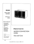
|ntroduction
Abbreviations Found In This Instruction
Thank You
for purchasing a Seats water heater.
Properly installed and maintained, it should give you years of
trouble free service° If you should decide that you want the new
water heater professionally installed, contact the local Sears
Service Center or any Sears store. They wilt arrange for prompt,
quality installation by Sears authorized contractors.
Product
MODEL
NUMBER
Specifications
TANK
CAPACITY DIMENSIONS ININCHES
HEIGHT
IN GALLONS DIAMETER
153,327165
153,327166
30
23"
30¼"
153,327265
153.327266
40
25 °
32¼"
30
I9"
46¼"
40
19"
60"
21"
23"
58_"
60_"
25"
59_"
t53,327365
153,327366
t53.327465
153.327466
153.327565
153.327566
153',327665
I53,,327666
153327865
153327866
80
ELEMHWF
WATTAGE
MINIMUM
AT 240 VOLTS
WIRE SIZE*
UPPER
LOWER
(GAUGE)
RECOVERYRATE
GALS. PER HOUR
@90°E RISE
50
66
Manual
UL-Underwriters Laboratories, 333 Pfingsten Rd. Northbrook,
IL 60062
National Electrical Code-This publication is available from your
local government or public library or electric company or by
writing to UL.above.
ANSI-American National Standards Institute
17.3
25,0
17,3
25.0
t7.3
25.0
!7.3
25.0
!7.3
25.0
17.3
25.0
17.3
25.0
.
.
-
3800
5500
3800
5500
3800
3800
3800
5500
3800
3800
3800
3800
3800
3800
3800
3800
.
.
3800
5500
3800
5500
3800
5500
3800
5500
:
,
.
MAXIMUM FUSE
OR CIRCUIT
BREAKER
SIZE (AMI'S)
12
I0
I2
10
20
30
20
30
12
t0
20
30
12
10
12
t0
12
10
12
t0
.
.
20
30
20
30
20
30
20
30
*Wiring size based on standard 60°C copper wire. If distance from fuse box m water heater is more than 90 feet, refer to your local electrica! code.
.ring for the New installation
Read the "Safety Precautions" section, page 2 of this manual
first and then the entire manual carefully If you don't follow
the safety rules, the water heater will not operate properly. It
could cause DEATH, SERIOUS
BODILY INJURY
AND/OR PROPERTY DAMAGE.
This manual contains instructions for the installation, operation, and maintenance of this electric water heater. It also
contains warnings throughout the manual that you must read
and be aware of. All warnings and all instructions are essential
to the proper operation of the water heater and your safety.
Since we cannot put everything on the first few pages, READ
THIS ENTIRE MANUAL BEFORE ATFEMPTtNG TO
INSTALL OR OPERATE THE WATER HEATER
The installation must conform with the instructions in this
manual; electric company rules; and Local Codes, or in the
absence of Local Codes, with the current edition of the
National Electrical Code, This publication is available from
your local government or public library or electric company
or by writing Underwriters Laboratories, 333 Pfingsten Road,
Northbrook, IL 60062.
• If after reading this manual you have any questions or do not
understand any portion of the instructions, call Sears Service
Center.
" Carefully plan the place where you are going to put the water
heater. Correct electrical wiring and connections are very
important in preventing death from possible electrical shock
and fires,
Examine the location to ensure the water heater complies
with the "Facts to Consider About the Locatioff' section,
For California installation this water heater must be braced,
anchored, or strapped to avoid falling or moving during an
earthquake. See instructions for correct installation procedures. Instructions may be obtained from the California
office of the State Architect, 400 P Street, Sacramento, CA
95814
Materials
Materials
an
eeded
Basic Tools
Needed
To simplifit the installation Sears has available the inst£Iation
parts shown below You may or may not need all of these materials, depending
on your type of installation
r .......
DRAIN PANS AVAILABLE IN 20"
DIAHETER FOR WATER HEATERS
HAVING A DIAMETER 18" OR LESS,
24" DIAHETER
FOR WATER HEATERS
HAVING A DIAMETER 22" OR LESS
AND AVAILABLE IN 28" DIAHETER
FOR WATER HEATERS HAVING A
DIAHETER 7.6" OR LESS
WATER HEATER HEAT TRAPS
HELP REDUCE HEAT LOSS DUE
TO THERHAL SYPHONING
EXPANSION
TANKS FOR THERHAL
EXPANSION
CONDITIONS
AVAILABLE
IN 2 GALLON AND 5 GALLON CAPACITY
THROUGH
LOCAL SEARS SERVICE
CENTERS
WATER HEATER INSTALLA.
TION KIT WITH FLEXIBLE
CONNECTORS
FOR 3f4" OR
1/2" THREADED
OR COPPER
PLUHBING
szSiCTools
You may or may not need all of these tools, depending on your
type of installation, These tools can be purchased at your !ocal
SL_I[_
store°
Pipe Wrench (2)
Screwdriver
6 Foot Tape or Folding Rulo
Garden Hose
Drill
Pipe Dope or Teflon Tape
ADDITIONAL
TOOLS NEEDED
WHEN
SWEAT SOLDERING
Tubing
Cutters
Propane
Torch
Soft Solder
Solder
Flux
or
Hacksaw
Emery
Cloth
".-=Cite B._ushes
HACKSAW
6 FOOT
GARDEN
TAPE
HOSE
314" WIRE BRUSH
SLOT-HEAD
PHILLIPS
SCREW
DRIVER
PIPE
WRENCH
1f2" WIRE BRUSH
SCREWDRIVER
PROPANE
ROLL OF LEAD FREE
SOFT SOLDER
TORCH
PIPE DOPE
(SQUEEZE TUBE)
ROLL OF TEFLON
(Use
only
on water
TAPE
connections)
DRILL
ROLL OF EMERY
CLOTH
SOLDER
FLUX
TUBING
CUTTER
Installation
Removing
Heater
Turn "OFF"
Instructions
the Old Water
Q
a. If you have copper piping to the water
heater, the two copper water pipes can be
cut with a hacksaw approximately 4" away
from where they connect to the water
heater. This will avoid cutting off the pipes
too short. Additional cuts can be made
later if necessary: Disconnect the temperature-pressure relief valve drain line. When
the water heater is drained, disconnect the
hose from the drain valve. Close the drain
valve_ The water heater is now completely
disconnected and ready to be removed,
Q
b. If you have galvanized pipe to the water
heater, loosen the two galvanized pipes
with a pipe wrench at the union in each
line. Also disconnect the piping remaining
to the water heater_ These pieces should be
saved since they may be needed when
reconnecting
the new water heater.
Disconnect the temperature-pressure relief'
valve drain line. When the water heater is
drained, disconnect the hose from the
drain valve Close the drain valve° The
water heater is now completely disconnected and ready to be removed.
electrical supply to the water heater.
®
Q
Turn "OFF" the water supply to the
water heater at the water shutoffvalve or
water
meter_
QAttach
a hose to the water heater drain
valve and put the other end in a floor
drain or outdoors Open the water heater
drain valve, Open a nearby hot water
faucet which will relieve pressure in the
water heater and speed draining.
J
_,WARNING
The water passingour=lye
may be extremely hot. To avoid being scalded, make sure all connections
are tight and that the water flow is directed away from
any person,
Q
Check again to make sure the electrical supply is
turned "OFF" to the water heater. Then disconnect
the electrical supply connection from the water
heater junction box,
Mineral buildup or sediment may have accumulated in the[
old water heater, This causes the water heater to be[
much heavier than norma! and this residue, if spilled out, I
cou d causestain rig.
I
installation
Facts to Consider
Location
instructions
About
the
You should carefully choose an indoor location for
water heater, because the placement is a veI3, important
eration for the safety of the occupants in rkle building
the most economical use of the appliance This water
not intended for outdoor installation.
the new
considand for
heater is
Whether replacing an old water heater or putting the water
heater in a new location, the following critical points must be
observed.
The location selected should be indoors as close to and as
centralized with the water piping system as possible. This
water heater, as well as all water heaters, will eventually leak_
Do not install without adequate drainage provisions where
water flow will cause damage..
CAUTION
WATER HEATERS EVENTUALLY LEAK= Installation of the
water heater must be accomplished in such a manner that if
the tank or any connections should leak, the flow of water
will not cause damage to the structure. For this reason it is
not advisable to nstal the water heater in an attic or upper
floor. When such locations cannot be avoided, a suitable
drain pan should be installed under the water heater° Drain
_ans are available at your local Sears Store. Such a drain pan
must be piped to an adequate drain. Under no circumstances
is the manufacturer or Sears to be held liable for any water
damage in connection with this water heater.
(toni'd)
Facts to Consider About The
Convertible
Lower Element
The Upper Element (if a double element model), is a conventional 3800 watt element which only operates at its rated
wattage on 240 volts (See rating plate on water heater)
The Lower Element of the water heater can be converted from
operation at 3800 watts to 5500 watts on a 240 volt system.
Read and follow water beater warnings and instructions If after
reading these instructions in this manual, if you do not understand any portion, call Sears Service Center.
AWARNING
Before making the conversion to 5500 watts, check the
AW
I) power supply..must be 240 volts, (2) wiring... 10 gauge
G, Type TW, 60°C or equivalent,
and (3) Circuit
breakers or fusing...capabte
of 30 amp loading. Also, the
installation must conform with this manual, local codes
and electric utility rules. Failure to comply can result in
DEATH,
SERIOUS
BODILY INJURY, OR PROPERTY
DAMAGE.
A CAUTION
INSTALLATION
IN RESIDENTIAL
GARAGES:
The
water heater must be located andlor protected so it is
not subject to physical damage by a moving vehicle.
• The location selection must provide adequate clearances for
servicing and proper operation of the water heater.
NOTE: Whether or not the element conversion is made the
model rating plate must be marked_ Using a hardpoint
ink
pen, check the appropriate
block within the model rating
plate, which is located adjacent to the lower access panel.
installation
Water
instructions
(cont'd)
Piping
AWARNING
HOTTER
WATER CAN SCALD: Water
heaters are
intended to produce hot water. Water heated to a tem)erature which will satisfy space heating, clothes washing,
dish washing, and other sanitizing needs can scald and
)ermanently injure you upon contact_ Some people are
more likely to be permanently injured by hot water than
others. These include the elderly, children, the infirm, or
physically/mentally
handicapped.
If anyone using hot
water in your home fits into one of these groups or if
there is a local code or state law requiring a certain tem)erature water at the hot water tap_ then you must tal(e
special precautions. In addition to using the lowest possible temperature
setting that satisfies your hot water
needs, a means such as a mixing valve, shall be used at
the hot water taps used by these people or at the water
heater. Mixing valves are available at plumbing supply or
hardware stores. Follow manufacturers instructions for
installation of the valves_ Before changing the factory setting on the thermostat,
read the "Temperature
Regulation" section in this manual.
Installation
completed
using Sears
Installation Kit
FLEXIBLE
WATER
CONNECTORS
.OTOUTLET
314" THREADED
NIPPLE
VALVE
COLD INLET
WATER LINE
THREADED TO
SWEAT COUPLING
TO HOUSHEREAD_DTO
SWEAT COUPLING
SHUT-OFF
_
"<---'--3/4"THREADED
NIPPLE
The illustration shows the attachment of the water piping to the
water heater. The water heater is equipped
with ¾" water
conNectlons_
If a water heater is installed in a closed water supply system;
such as one having a back-flow preventer, check valve, water
meter with a check valve, etc, in the cold water supply; means
shall be provided to control thermal expansion, Contact the
local utility or local Sears Service Center on how to control this
situation,
TEMPERATURE.
PRESSURE
RELIEF VALVE
)ISCHARGE
PIPE
(Do not cap or plug)
NOTE: If using copper tubing, solder tubing to an adapter
before attaching the adapter to the cold water inlet connection. Do not solder the cold water supply line directly to the
cold water inlet. It will harm the dip tube and damage the
taul_
• Look at the top cover of the water heater. The water oudet is
marked hot Put two or three turns of teflon tape around the
threaded end of the threaded-to-sweat coupling and around
both ends of the ¾" threaded nipple. Using flexible connectors, connect the hot water pipe to the hot water outlet of the
water heater
6" AIR GAP
• Look at the top cover of the water heater The cold water inlet
is marked cold. Put two or three turns of teflon tape around
the threaded end of the threaded-to-sweat
coupling and
around both ends of the ¾" threaded nipple, Using flexible
connectors, connect the cold water pipe to the cold water
inlet of the water heater.
NOTE: Your water heater is super insulated to minimize
heat loss from the tanl¢_ Further reduction in heat loss can be
accomplished
by insulating the hot water lines from the
water heater.
FLOOR
DRAIN
IJnstallation
Instructions
Temperature=Pressure
Relief Valve
_k WARNIfNG
At the time of manufacture this water heater was provided
with a combination temperature-pressures relief valve certified by a nationally recognized testing laboratory
that
maintains periodic inspection of production of listed equipment or materials, as meeting the requirements for Relief
Valves and Automatic Gas Shutoff Devices for Not Water
Supply Systems, and the current edition of ANSI Z21,22
and the code requirements of ASHE+ If replaced, the valve
must meet the requirements of local codes, but not less
than a combination temperature and pressure relief valve
certified as meeting the requirements for Relief Valves and
Automatic
Gas Shutoff Devices for Hot Water Supply
Systems, ANSI Z21.22 by a nationally recognized testing
laboratory that maintains periodic inspection of production
of listed equipment or materials.
The valve must be marked with a maximum set pressure
not to exceed the marked hydrostatic working pressure of
the water heater (150 Ibs. p.sJ.) and a discharge capacity
not less than the water heater input rate as shown on the
model rating plate. (Electric heaters - watts divided by
1000 x 3412 equal BTU/Hro rate.)
Your local jurisdictional
authority, while mandating the use
of a temperature-pressure
relief valve complying with
ANSI Z21.22 and ASME, may require a valve model different from the one furnished with the water heater.
Compliance with such local requirements must be satisfied
by the installer or end user of the water heater with a
locally prescribed
temperature-pressure
relief valve
installed in the designated opening in the water heater in
place of the factory furnished valve.
For safe operation of the water heater, the relief valve
must not be removed from it's designated opening or
plugged.
The temperature-pressure
relief valve must be installed
directly into the fitting of the water heater designated for
the relief valve. Position the valve downward and provide
tubing so that any discharge will exit only within 6 inches
above, or at any distance below the structural floor. Be certa!n th_t .nocontact ismade with any th,
e e!ectrical p_rt+
The dischargeopening must not be blocked or reduced in
size under any circumstances.Excessive length,over 30
feet, or use of more than four elbows can cause restriction
and reduce the discharge capacity of the valve°
No valve or other obstruction is to be placed between the
relief valve and the tank. D,o not connect tubing directly to
discharge drain unless a 6 air gap is provided. To prevent
bodily injury, hazard to life, or property damage, the relief
valve must be allowed to discharge water in quantities
should circumstances demand. If the discharge pipe is not
connected to a drain or other suitable means, the water
flow may cause property damage.
The Discharge Pipe:
, Must not be smaller in size than the outlet pipe size of
the valve, or have any reducing
couplings or other
restriction+
• Must not be plugged or blocked+
• Must be of material listed for hot water distribution.
• Must be installed so as to allow complete drainage of
both the temperature-pressure
relief valve, and the dis.
charge pipe.
• Must terminate at an adequate drain.
• Must not have any valve between the relief valve and
tank,
(cont'd)
_k WARNING
The temperature-pressure
relief valve must be manually
operated at least once a year. Caution should be taken to
ensure that (I) no one is in front of or around the outlet
of the temperature-pressure
relief valve discharge line,
and (2) the water manually discharged wilt not cause any
bodily injury or property damage because the water may
be extremely ho_
If after manually operating the valve, it fails to completely
reset and continues to release water, immediately, close
the cold water inlet to the water heater, follow the draining instructions, and replace the temperature-pressure
relief valve with a new one.
HOT
COLD
HOT
PRESSURE
RELIEF VALVE
(Do not cap or plug)
T&P REUEF
VALVE FROEE
'TEMPERATURE.
PRESSURE
REUEF VALVE
|nstallation
Filling the Water
Instructions
(cont'd)
Heater
To fill the water heater with water:
. Close the water heater drain valve by turning the handle to
the right (clockwise).. The drain valve is on the lower front of
the water heater.
= Open the cold water supply valve to the water heater
NOTE: The cold water supply valve must be left open
when the water heater is in use,
• To insure complete filling of the tank, allow air to exit by
opening the nearest hot water faucet. Allow water to run
until a constant flow is obtained. This will let air out of the
water heater and the piping.
A CAUTION
Never use this water heater unlessit is completely full of
water. To prevent damage to the tank and heating element, the tank must be filled with water. Water must
flow from the hot water faucet before turning "ON"
power,
•
NOTE: Whether or not the element conversion is made the
model rating plate must be marked. Using a hardpoint
ink
pen, check the appropriate block within the model rating
plate, which is located adjacent to the lower access panel.
Check all new water piping for leal_ Repair as needed,
Converting
Element
Necessary element conversion parts are located in a small bag
contained within the electrical junction box on top of the water
heater°
the Lower
CONVERSION
PARTS
These instructions only cover the conversion of the convertible
element, read this entire manual before attempting to install or
operate the water heater. The water beater is factory set to operate at 3800 watts. The lower element can be converted to operate at 5500 watts, Refer to the Facts to Consider About the
Convertible Lower Element" section.
SCRE_W
The Upper Element, (ira double element model) is a conventional 3800 watt element which only operates at its rated
wattage on 240 volts.. (See rating plate on water heater).
BUSS
The Lower Element of the water heater can be converted from
operation at 3800 watts to 5500 watts on a 240 volt system.
BAR
Io Before beginning the conversion turn "OFF" electric power
supply to the water heater
If after reading these instructions and this manual, if you do not
understand any portion, call Sears Service Center.
AWARNING
Before making the conversion to 5500 watts, check the
(I) power supply...mustbe 240 volts, (2) wiring... 10 gauge
AWG, Type TW, 60°C or equivalent, and (3) Circuit
breakers or fusing..capable of 30 amp loading. Also, the
installation must conform with this Manual, local codes
and electric utility rules. FAILURE TO COMPLY CAN
RESULT IN DEATH, SERIOUS BODILY INJURY OR
PROPERTY DAMAGE.
AWARNING
HAZARD OF ELECTRICAL SHOCKI Before removing
any access panels or servicing the water heater, make
sure the electrical supply to the water heater is turned
"OFF". FAILURE TO DO THIS COULD RESULT IN
DEATH, SERIOUS BODILY INJURY, OR PROPERTY
DAHAGE.
10
Installation
Instructions
(cont'd)
2. The convertible element is located behind the lower access
panel of the water heater, Remove the two screws securing
the access panel, and remove panel,
5, Remove the screws from terminal 2 of the element, and move
the looped end of the wire aside.
3, Remove the insulation block to expose the opening,_
6, The buss bar is labeled 5500 W. Place the buss bar over terminals 2 and 3 with the 5500 W visible. Install the extra screw
provided into terminal 3,
S5OOW
7, The wire removed from terminal 2 has a looped end, It must
remain looped and now be placed (as shown) on top of the
buss bar, over the opening of terminal 2, and secured using
the remaining screw°
4o Lower Element: Lift out the tab as shown to unclip the
terminal cover from the thermostat, The terminal cover can
now be removed from the thermostat
TERMINAL
CUPPED
H OSTAT
POINT
COVER
pLASTIC
TO THERAT THIS
TABS
ON
/BOTH
SIDF_ OF
TERMINAL
COVER
HOLD IT tN
PLACE_
8. Tighten terminals
connection,
LOWER
THERHO_TAT
JACKET
11
2 and 3 to ensure proper
electrical
installation
Instructions
(cont'd)
Converting
the Lower
Element (cont'd)
9, Replace terminal cover on thermostat making sure that the
loddng tabs on the terminal cover are in place
_WARNING
12, Complete wiring to the water heater, or if completed, turn
"ON" electric power to the water heater after filling the
tank with water.
]
Make sure the ther_gainst
the tank, the |
terminal cover is in place, and the insulation is replaced. |
Fmlure to do so can result in DEATH, SERIOUS BODILY|
INJUR_, OR PROPERTY DAMAGE.
]
l& Replace the insulation block so that it completely covers
the thermostat and element,
,_ CAUTION
Never use this water heater unless it is completely full of
water. To prevent damage to the tank and heating element, the tank must be filled with water. Water must
flow from the hot water faucet before turning "ON"
power.
11o Replace the access panel.
12
installation
Wiling
Instructions
Diagrams
(cont'd)
TO ELECTRIC
POWER SUPPLY
STANDARD WIRING
FOR
2 WIRE LEAD WATER HEATERS
NON-SIMULTANEOUS
OPERATION
240 VOLT DOUBLE ELEMENT
BLACK
UPPER E.CoO. &
THERMOSTAT
BUSS BAR
RED
.I
w
UPPER
ELEMENT
FOR 5500 WATTS
..................
=H,==,
i1 ,1,, ,,111
WIRING FOR 3 WIRE LEAD WATER
NON-SIMULTANEOUS
OPERATION
240 VOLT DOUBLE
=
HEATERS
ELEMENT
YELLOW
......
THREE TYPES
• _
OF FIELD
HAVE
i Illll Ill'
=d
UPPER E.C.O. &
THERMOSTAT
TIME CLOCK
OPEPJ_TES BOTTOH
TOELECTRIC
_
POWER SUPPLY
L!
i
SWITCH
ELEMENT
CONNECT,ONS
MAY
L2 _
• L_ L2
_
ONLY
TOTIHE
CLOCK SWITCH
JUNCTION
YELLOW
l
i1===
BOX
*:_SLUE_ BLACK
=
BUSS BAR_
!
_v/_
"_
"OFF PEAK" HETER
OPERATES BOTTOH
ELEHENT
U PPER
TO ELECTRIC
ELEHENT
POWER
_
SUPPLY
L2LIL2
LI
t_
-_
1
[_
_NOTE: Some Lower Hi-Temp
Switches may have 4 terminals°
only the 2 terminals on left,
"_
Limit
Use
HETER
BOX
"_ BLUE1 BLACK
i
i
i
FOR TWO'W_RE
TO ELECTRIC
,--'1"-----t
POWER SUPPLY
LI
FOR 3800 WATTS
PEAK
IUNffTION
YELLOW|
,OR
,,00
WATTS
ONLY
TO:'OFF
="1
_
LOWER
HEATING ELEMENT
1,3
i
, i
ii
ii1,Iii
CONNECTION
L_
installation
Instructions
(cont'd)
Wiring
IkCAUTION
Co Flexible metal conduit or flexible metallic tubing shall be
permitted for grounding if all the following conditions are
I
Never use this water heater unlessit is completely full of I
water. To prevent damage to the tank and heating ele- I
ment, the tank must be filled with water. Water must]
flow from the hot water faucet before turning on power, i
meg:
1 The length in any ground return path does not exceed
6 feet,
2,, The circuit conductors contained therein are protected
by overcurrent devices rated at 20 amperes or less.,
You must provide all wiring of the proper size outside of the
water heater. You must obey local codes and electric company
requirements when you install this wiring_
3 The conduit or tubing
approved for grounding.
If you are not familiar with electric codes and practices, or if you
have any doubt, even the slightest doubt, in your ability to connect the wiring to this water heater, obtain the service of a competent decrrician, Contact your Seats salesperson to arrange for
a professional electrician,
is terminated
in fittings
For complete grounding details and all allowable exceptions,
refer to the current edition of the National Electrical Code,
4. A standard W' conduit opening has been made in the water
heater junction box for the conduit connection.,
Wiring Diagrams (See Wiring Diagrams Section) have been
supplied showing the two most common types of connections between the water heater and the power supply, You can
easily see which type connection you have by removing the
junction box cover on top of the water heater,
_IWARNING
WATER HEATERS EQUIPPED FOR ONE VOLTAGE
ONLY: This water heater is equipped for one type voltage
only. Check the rating plate near the bottom accesspanel
for the correct voltage. DO NOT use this water heater
with any voltage other than the one shownon the model
rating plate. Failure to use the correct voltage can cause
problems which can result in DEATH, SERIOUS BODILY
INJUR_, OR PROPERTY DAMAGE. if you have any questions or doubts consult your electric company.
A. Two W'tre Connection Diagrams: is the most common
requiring you to simply connect red to red, black ro black,
and the ground wire to the green ground screw in r_hejunction box of the water heater_
B. Three Wire Connection
Diagram:
is used when you are
connecting the water heater to power a supply that has a
_Time Clock" or "Off Peak" Meter. To malce these connections refer to block I or 2 in this wiring diagram for the type
of system you have.
_i, CAUTION
If wiring from your fuse box or circuit brealter box was
aluminum for your old water heater, replace it with copper wire° If you wish to reuse the existing aluminum wire,
have the connection at the water heater made by a competent electrician. Contact your Sears salesperson to
arrange for a professionalelectrician,
NOTE: If you have purchased
a three wire connection
water heater but you are not on a "Time Clock" or "Off
Pea.k" meter and have a standard
two wire connection
lower supply, simply follow the connection
diagram in
lock .3 of the Three Wire Connection
Diagram_
6_
t Provide a way to easily shut off the electric power when working on the water hearer_ This could be with a circuit breaker
or fuse block in the entrance box or a separate disconnect
switch
Use wire nuts and connect the power supply wiring to the
wires inside the water heaters junct'on
7, The water heater must be electrically "grounded" by the
installer, A green ground screw has been provided on the
water heater's junction box° Connect ground wire to this
location,
2, Install and connect a circuit directly from the main fuse or
circuit breal_er box,. This circuit must be the right size and
have its own fuse or circuit breaker,. Refer to the chart in the
"Product Specifications" section for the correct size wire and
fuse or circuit breaker_
8. Replace the wiring junction cover using the screw provided.
3. If'metal conduit is used for the grounding conductor:
WIRE
NUTS
A. The grounding electrode conductor shall be of copper,
aluminum, or copperclad aluminum. The material shall
be of one continuous length without a splice or joint.
CONDUIT
B. Rigid metal conduit, intermediate metal Conduit, or electrical metallic tubing may be used for the grounding
means if conduit or tubing is terminated in fittings
approved for grounding,
' GREEN
GROUND
SCREW
I4
Installation
installation
Instructions
Checklist
• Whether or not the element conversion is made, the model
rating plate must be marked. Using a hard point ink _en,
check the appropriate block within the model rating p_ate,
which is located adjacent to the lower access panel.
•
(cont'd)
COLD
HOT
Is the fuse or circuit breaker size correct as shown in the chart
in the "Product Specifications" section?
CONDUIT
• Are the wires from the circuit breaker or fuse service to the
water heater's junction box on the correct wire size (gauge) as
shown in the chart in the "Product Specifications" section?
o Is the new temperature-pressure
relief valve properly
installed, andpiped to an adequate drain? See TemperaturePressure Relief Valve section
TEMPERATURE-
Is the water heater completely filled with water. See Filling
the Water Heater" instructions
in the "Installation
Instructions" section,
RELIEF VALVE
Will a water leak damage anything? See "Facts to Consider
About the Location" secuon.
Are the cold and hot water lines connected to the water heater
correctly? See "Water Piping" instructions in the "Installation
Instructions
section
Is there adequate clearance for maintenance around the water
heater?
_g
(Do not cap or plug)
Do you need to call your electric company to check your
wiring?
6
FLOOR
MODEL RATING
15
PLATE
AIR GAP
DRAIN
Service
and Adjustment
Temperature
Regulation
AWARNING
The lower thermostat is factory set at its lowest position which
approximates 120°F (Hot) andis adjustable if a different water
temperature is desired, Read all warnings in this manual and on
the water heater before proceeding.
HOTTER WATER CAN SCALD: Water heaters are
intended to produce hot water. Water heated to a temperature which will satisfyspace heating, clothes washing,
dish washing, and other sanitizing needs can scald and
permanently injure you upon contact. Some people are
more likely to be permanently injured by hot water than
others. These include the elderly, children, the infirm, or
physically/mentally handicapped. If anyone using hot
water in your home fits into one of these groups or if
there is a local code or state law requiring a certain temperature water at the hot water tap, then you must take
special precautions. In addition to using the lowest possible temperature setting that satisfies your hot water
needs_a means such as a mixing valve, shall be used at
the hot water taps used by these people or at the water
heater. Mixing valves are available at plumbing supply or
hardware stores° Follow manufacturers instructions for
installation of the valves_Before changingthe factory setting on the thermostat,
read the "Temperature
Regulation" section in this manual.
Temperature
Settings
HOT-Is a thermostat setting of approximately ]20°F,
which wilt supply hot Water a(the most economical temperatures,
A-Is a thermostat setting of approximately 130°E
B-Is a thermostat setting of approximately 140°E
C--Is a thermostat setting of approximately 150°E
VERY HOT- Is,a thermostat setting of approximately 160oh It
is recommended that the dial be set lower
whenever possible,
NOTE: Water temperature range of I20°--140°F
mended by most dishwasher manufacturers.
AWARNING
Never allow small children to use a hot water tap, or to [
draw their own bath water. Never leave a child or handicappedperson unattended n a bathtub or shower.
recom-
Upper Thermostat
Adjustment
Thermostats
l'he thermostat(s) of this water heater have been factory set at
their lowest position which approximates 120°F (Hot) to reduce
the risk of scald injury,
NOTE: It is not necessary to adjust the upper thermostat.
However_ if it is adjusted above the factory set point of
120°F (HOT) is is recommended that it not be set higher
than the lower thermostat setting.
The upper thermostat (dual element models only) is factory set
at its lowest position which approximates t20°F (Hot) and is
adjustable if a different water temperature is desired. Read all
warnings in this manual and on the water heating before proceeding,
The upper thermostat is adjustable if a different water temperature is desired, Read all warnings in the "TemperatureRegulation" section before proceeding
In _Furn "OFF" the electrical power to the water heater at the
junction box°
2, Take "OFF" the access panel°
@
3. The slotted adjustment (using a screwdriver) can be turned
ctoclcwise (_-_ _.,.J) to increase the temperature setting or
counter cloclcwls'_
e (_..fli)
to decrease the temperature
setungo
u_amm
4
4, Replace the access panel
7@
el
5. Turn "ON" the power supply,,
(DUAL
ELEHENT
HODELS
ONLY)
UPPER THERHOSTAT
ADJUSTABLE
BEHIND
UPPER ACCESS PANEL
16
(cont'd)
Service and Adjustment
Lower
Thermostat
Adjustment
Failure to install and maintain a new properly listed temperature-pressure relief valve will release the manufacturer from any
claim which might result from excessive temperature or pressure,,
The lower thermostat is adjustable if a different water temperature is desired.
Read all warnings
in the 'TemperatureRegulation" section before proceeding.
The slotted adjustment
(using a screwdriver)
can be turned
clockwise (_)
to increase the temperature
setting or
counter clockwise to (k,._)
decrease the temperature setting.
AWARNING
If the temperature-pressure
relief valve on the appliance
weeps or discharges periodically, this may be due to ther *'
real expansion. Your water heater may have a check valve
installed in the water line or a water meter with a check
valve. Consult your local Sears Service Center for further
information. Do not plug the temperature-pressure
relief
valve.
g.
Draining
The water heater should be &ained if' being shut down during
freezing temperatures.
Also periodic draining and cleaning of
sediment from the tank may be necessary.
•
turn
"OFF"
the electric
power
supply to
AWARNING
LOWER THERNOSTAT
ADJUSTABLE
THROUGH
LOWER ACCESS PANEL
Temperature=Pressure
Valve Operation
Befbre beginning
the water heater
HAZARD
OF ELEC_K!
Before removing|
any access panels or servicing the water heater, make|
sure the electrical supply to the water heater is turned|
"OFF"° Failure to do this could result in DEATH, SERI-|
OUS BODILY INJURY, OR PROPERTY DAHAGE.
J
Relief
" CLOSE the cold water inlet valve to the water heater._
The temperature-pressure
at least once a year..
retiefvaJve
must be manually
operated
-
OPEN a nea*by hot water faucet and leave open to allow for
draining.
,
Connect
adequate
•
OPEN
TEHPERATURE-PRESSURE
RELIEF VALVE
a hose to the drain
drain or outdoors.
the
water
heater
valve and
drain
valve
terminate
to allow
to an
for tank
draining.
DISCHARGE
NOTE: If the
drained fot an
left open with
to an adequate
PIPE
water heater is going to be shut down and
extended period, the drain valve should be
hose connected
allowing water to terminate
drain.
•
Close the drain valve+
•
Follow "Filling
the Water Heater"
"Installation Instructions" section+
•
Turn "ON" power to the water heater.
AWARNING
The temperature-pressure
relief valve must be manually
operated at least once a year. Caution should be taken to
ensure that (I) no one is in front of Or around the outlet
of the temperature-pressure
relief valve discharge line,
and (2) the water manually discharged will not cause any
property damage or bodily injury. The water may be
extremely hot.
If after manually operating the valve, it fails to completely
reset and continues to release water, immediately close
the cold water inlet to the water heater, follow the draining instructions, and replace the temperature-pressure
relief valve with a new one.
I
instructions
in the
ACAUTION
Never use this water heater unless it is completely fult
water. To prevent damage to the tank and heating eleI ment, the tank must be filled with water. Water must
I flow from the hot water faucet before turning "ON"
L_power.
17
Service
and Adjustment
(cont'd)
Element Cleaning/
Replacement
3, Attach a hose to the water heater drain valve and put the
other end in a floor drain or outdoors. Open the water heater
drain valve. Open a nearby hot water faucet which will relieve
pressure in the water heater and speed draining,
NOTE: These instructions are written for element cleaning
and element replacement for the lower element. If it is necessasy to dean or replace the upper element, then repeat these
instructions.
To remove
replace it:
the element
1_ Before beginning
water heater,
from your
turn "OFF"
tank
in order
to clean or
the electric power supply to the
j
AWARNING
The water passingout of t_alve
may be extremely hot. To avoid being scalded, make sure all connections
are tight and that the water flow is directed away from
any person_
4_ Remove the two screws securing
remove panel,
the access panel, and
AWARNING
HAZARD OF ELECTRICAL SHOCK! Before removing
any access panels or servicing the water heater, make
sure the electrical supply to the water heater is turned
"OFF". Failure to do this could result in DEATH, SERIOUS BODILY INJURY,OR PROPERTY DAMAGE.
2, Turn off the water supply to the water heater at the water
shutoff valve or water meter_
5, Remove the insulation
18
block to expose the opening.
6. Lift out the tab as shown to unclip file terminal cover from
the thermostat. The terminal cover can now be removed
from the thermostat..
TERHtNAL
COVER
CLIPPED
TO THER*
HOSTAT AT THIS
POINT
A WARNING
Replacement elements must (I) be the same voltage and
(2) no greater wattage than listed on the model rating
plate affixed to the water heater.
lOr A new gasket should be used in all cases to prevent a possible water leak. (See Hement Gasket in the "Parts Order
List" Chart). Place the new element gasket on the thread
side of the cleaned or new element and screw into tank.
securing tightly using an element wrench
PLASTIC
TABS OH
BOTH BIDES OF
/TEKH|NAL
COVER
HOLD IT IN
PLACE
LOWERTHERHOSTAT
11. Close the water heater drain valve by turning the handle to
the right (clockwise). The drain valve is on the lower front
of the water heater°
12 Open the cold water supply valve to the water' heater.
NOTE: The cold water supply valve must be left open
when the water heater is in user
13 To insure complete filling of the tank, allow air to exit by
opening the nearest hot water faucet. Allow water to run
until a constant flow is obtained This will let air out of the
water heater and the piping..
TERHINAL
COVER
UPPER
ON
THERHOSTAT
A CAUTION
I
Never use this water heater unlessit is completely full of I
water, To prevent damage to the tank and heating ele-I
ment, the tank must be filled with water. Water must I
flow from the hot water faucet before turning "ON"
po;v_r.
7.. Disconnect the two wires on the element and unscrew the
old element from the tank_
14 Check element for water Iealcs. If leakage occurs, tighten
element or repeat steps 2 and 3, remove element and reposition gasket, Then repeat steps 10 through 14
I5, Reconnect the two wires to the element and then check to
make sure the thermostat remains firmly against the surface
of the tank,
8- Clean the area around the element opening. Remove any
sediment from or around the element opening and inside
the rank.
9. If you are cleaning the element you have removed, do so by
scraping or soaking in vinegar or a de-liming solution
19
Service
and Adjustment
(cont'd)
Element Cleaning/
Replacement
(cont'd)
Drain Valve Washer
Replacement
I6,, Replace terminal cover on thermostat maldng sure that the
locldng tabs on the terminal cover are in place.
NOTE: For replacement,
use a _%/' x 1_/_,,x W' thick washer
available
at your nearest hardware store. For ordering a
replacement washer, refer to the "Parts Order List" section.
I7
Replace the insulation block so that it completely covers the
thermostat and element,
° Before beginning
the water heater,,
turn
"OFF"
the electrical power
supply to
A WARNING
]
HAZARD OF ELEC_-_K!
Before removing I
any access panels or servicing the water heater, make I
sure the electrical supply to the water heater ts turned I
"OFF". Failure to do this could result in DEATH, SERI-I
OUS BODILY INJURY,OR PROPERTY DAMAGE.
]
• Follow "Draining" instructions. See "Draining" section_
• Turning counter clockwise, remove the hex cap below the
screw handle.
• Remove the washer and put the new one in place.
18 Replace access panel
• Screw the handle and cap assembly back into the drain valve
and retighten using a wrench_ DO NOT OVER TIGHTEN,
19_ Turn "ON" electric power to water heater.,
• Follow "Filling the Water Heater"
"Installation Instructions" section.,
instructions
in the
• Check for leaks,
• Turn "ON" electric power to the water heater.,
HAANDLE AND
P ASSEHBLY
_'WASHER
Service
Before calling for repair service, read the Start Up Conditions
and Operational Conditions found in the Troubleshooting
Guide of this manual.
If a condition persists or you are uncertain about the operation
of the water heater, let a qualified person check it out_
Contact SEARS Repair Services
(I-800-469-4663).
2O
at t_800.4-MY-HOME
Troubleshooting
Guide
Start Up Conditions
THERHAL
EXPANSION
HOT
COLD
Water supply systems may, because of such events as high line
pressure, frequent cut-offs, the effects of water hammer among
others, have installed devines such as pressure reducing vales,
check valves, back flowpreventers, e_c ._tocontrol these types of
problems. When these devices are not equipped with an internal
by-pass, and no other measures _e taken, the devices cause the
water system to be closed. As water is heated, it expands (thermal expansion) and closed systems do not allow for the expansion of heated water.
WATER HEATER
COLD WATER
;ITTtNG
VALVEWITH
BY-PASS
(z)
The water within the water heater tank expands as it is heated and
increases the pressure of the water system, tf the relieving point of
the water heater s temperature-pressure
relief valve "s reached, the
valve will relieve the excesspressure.
The temperatttre-pressure
relief valve is not intendedfor
the constant relief of thermal
expansion,
This is an unacceptable condition and must be corrected.
PRESSUREGAUGE
FLOOR, CEILING
WATER HEATER
COLD WATER
INLET FITTING
JOIST, ETC.
|
HOT
Expansion
_
COLD
Tank Specifications
STRAPHNG
Mode,T t C; oTD
tymens ou 1inInohes
I' peF ttiog
Diameter ___Length j On Tank
Number
153o331020 1
2
8inches
_53.33_o5o15
WATER
SHUTOFF
RECOHHENDED INSTALLATION
(VERTICAL HOUNTING)
It is recommended that any devices installed which could create a
closed system have a by-pass andtor the system have an expansion tank to relieve the pressure built by thermal expansion.
Thermal expansion tanks are available from Sears stores and
through the Sears Service Centers° Contact the local plumbing
inspector, water supplier and/or the Sears Service Center for
assistance in controlling these situations.
Thermal
0)
PRESSURE
REDUCING
t2_inches /
Ill
|
II|1Ii /I
PRESSURE
0)
REDUCINGINLETCOLD
VALVE WITH
_"Male
(I)
_ _oches
[_4_nchos
I _"M_e
BY-PASS
EXPANSION
'_
WATER
SHUTOFF
!
TANK
Expansion
Tank
Sizing
Inlet*
_rater
Expansion
Tank
Capacity
Needed
PRESSUREGAUGE
Water Heater Capacity (Gallons)
Pressure
40psi
30
2
40
2
60psi
70psi
2
2
2
2
50p,_
....
(2)
Chart
2
50
2
ALTERNATE RECOHHENDED
iNSTALLATiON
[[ 66
[ 5
82
5
[
5
5
(HORIZONTAL
HOUNTING)
2 I 5...... 5
[
5
5
5
5
80p_ t 2 I 5 t 5 I 5
STRANGE
5
SOUNDS
Possible noises due to expansion and contraction of some metal
parts during periods of heat-up and cool-down do not represent
harmfiil or dangerous conditions.
*Highest recorded inlet water pressure in a 24 hour period or
regulated water pressure.
NOTE: Expansion tanks are pre-charged with a 40 psi air
charge. If the inlet water pressure is higher than 40 psi, the
expansion tanks air pressure must be adjusted to match that
pressure, but must not be higher than 80 psi.
21
Troubleshootin
Operational
SMELLY
Guide
Conditions
WATER
RUMBLING
In each water heater there is installed at least one anode rod (see
parts section) for corrosion protection of the tank. Certain water
conditions wil! cause a reaction between this rod and the water.
The most common complaint associated with the anode rod is
one of a "rotten egg smell", This odor is derived from hydrogen
sulfide gas dissolved in the water. The smell is the result of tour
factors which must all be present for the odor to develop:
a a concentration ofsulfate in the supply water.
h little or no dissolved oxygen in the water.
c. a sulfate reducing bacteria within the water heater. (This
harmless bacteria is non-toxic to humans.)
d an excess of active hydrogen in the tank. This is caused by
the corrosion protective action of the anode_
NOISE
In some water areas, scale or mineral deposits will build up on
your heating elements. This buildup will ,,cause a rumbling noise
Follow
Element Cleaning/Replacement'
instructions
to clean
and replace the elements
HIGH
TEMPERATURE
SHUT
OFF SYSTEH
The water heater has a high limit shut off system with a reset
button located on the thermostat°
Follow the resetting instructions which refer to the high limit
behind the access panel,
Smelly water may he eliminated or reduced in some water heater
models by replacing the anode(s) with one of less active material,
and then chlorinating the water heater tank and all hot water
lines. Contact the local Sears Service Center for further information concerning an Anode Replacement Kit #9001453 and this
Chlorination Treatment
NOTE: If your water heater is connected m an "OFF PEAK"
clock, and uses the "3 wire lead" wiring diagram in the
'w_g;"tringDiagram" section, then the water heater will have a
hi=limit on both the upper and lower thermostats. Follow
the instructions to reset the hidimit behind the upper and
lower access panels.
If the smelly water persists after the anode replacement and chlorination treatment, we can only suggest that continuous chlorination and filtering conditioning equipment be considered to
eliminate the water problena_
• Before beginning, turn "OFF" electric'd power supply to the
water heater.
¢
I
Do not remove the anode leaving the tank unprotected°
doing so, all warranty on the water heater tank is voided.
"AIR"
IN HOT
WATER
By
FAUCETS
AWARNING
HYDROGEN GAS: Hydrogen gas can be produced in a
hot water system that has not been used for a long period of time (generally two weeks or more). Hydrogen gas
is extremely flammable and explosive. To prevent the
possibility of injury under these conditions, we recommend the hot water faucet be opened for several minutes at the Idtchen sink before any electrical appliances
which are connected to the hot water system are used
(such as a dishwasher or washing machine). If hydrogen
gas is present, there will probably be an unusual sound
similar to air escaping through the pipe as the hot water
faucet is opened. There must be no smoking or open
flame near the faucet at the time it is open.
AWARNING
HAZARD OF ELECTRICAL SHOCKI Before removing
any access panels or servicing the water heater, make
sure the electrical supply to the water heater is turned
"OFF". Failure to do this could result in DEATH, SERIOUS BODILY INJURY,OR PROPERTY DAHAGE.
22
Troubleshootin
HIGH
TEHPERATURE
SHUT
Guide
(cont:'d)
NOT
OFF SYSTEH
(cont'd)
In a new installation, the water heater may not be properly
connected° Make sure the cold water supply valve is open=
Review and check piping installation, Make sure that the
cold water line is connected to the cold water inlet to the
water heater and the hot water line to the hot water outlet
on the water heater
"
Make sure the electrical supply to your water heater is
"ON",
•
Check for loose or blown fuses in your water heater circuit.
Circuit breakers weaken with age and may not handle their
rated load and should be replaced.
•
Make certain the disconnect switch, if used, is in the "ON"
position.
•
Check to see the electric service to your house has not been
interrupted. If this is the case, con tact the electric company,
•
Are the thermostats set to the desired temperature?
"Temperature Regulation" section.
•
If you had experienced very hot water and now no hot
water, the problem may be due to the high temperature
shut off system. See High Temperature Shut Off System"
in the "Troubleshooting" section,
•
During very cold weather, the incoming water will also be
colder and it will require a longer time to become beared,
•
The hot water usage may exceed the capacity of the water
heater. If so, wait for water heater to recover after abnormal
demand, Also examine pipes and faucets for possible water
leaks,
•
If you can not determine the problem, then call the Sears
Service Department.
• Remove the insulation block to expose the opening,
_RESET
BUTTON
@
ron_ c¢*
• Replace the insulation block so that it completely covers the
thermostat and element
• Replace the access panel,
• Turn "ON" electric power to the water heater.
ACAUTiON
If the high limit must be reset again, call Sears Service
Department to find out why the high limit turned "OFF"
the electric power.
OR NO HOT WATER
•
, Remove the two screws securing the access panel and remove
panel
• Reset the high limit by pushing in the red button marked
"RESET"-
ENOUGH
WATER
IS TOO
See
HOT
Adjust the thermostat to a lower setting_ See the "Temperature
Regulation" section.
23
=rPou
eshooting
Guide
(cont'd)
Leakage Checkpoints
Use this guide to check a "Leaking" water heater, Many suspected "Leakers" are not leaking tanks, Often the source of the water
can be found and corrected,
I
If you are not tholoughly familiar with electric codes, the water
heater, and safety practices, contact your local Sears Service
Center to check the water Jleater,,
®
®
(_
@
[
Small amounts of water from temperature-pressure relief
valve may be due to thermal expansion or high water
pressure m your area_
*The temperature-pressure
the tank fitting.
The elements
retief valve may be leaking at
may be lealdng at the tank fitting
AWARNING
Turn electrical power "OFF", remove access panels and
fold back insulation tf leaking around elements, follow
proper draining instructions and remove element.
Reposition or replace gasket on element. Place element
into opening and tighten
........ securely. Then follow "_illing
the Water Heater instructions In the Installat,on
Instructions secnon,
®
©
]
ACAUT'ON
1
Never use this water heater unlessit is completely full of 1
water. To prevent damage to the tank and heating element, the tank must be filled with water. The water must f
I flow from the hot water faucet before turning "ON"
Lpower.
I
'_Condensation may be seen on pipes in humid weather or
pipe connections may be leaking_
HAZARD OF ELECTRICAL SHOCKI Before
removing any access panelsor servicing the water
heater, make sure the electrical supply to the water
heater is turned "OFF". Failure to do this could
result in DEATH, SERIOUS BODILY INJURY, OR
PROPERTY DAMAGE°
®
A CAUTION
Read this manual first, then before cheddng the water|
heater make sure the electric supply has been turned |
"OFF", and never turn the electric supply "ON" before |
the tank iscompletely full of water.
/
Water from drain valve may be due to the valve being
opened slightly
*The drain valve may be leaking at the tank fitting,
*Water in the water heater bottom or on the floor may be
from condensation, loose connections or the temperature-pressure relief valve. DO NOT replace the water
heater until a full inspection of all possible water sources
is made and necessary corrective steps taken,
Leakage from other appliances, water lines, or ground
seepage should also be checked,
NOTE: To check where threaded portion enters
tank, insert cotton swab betweenjadcet opening and
fltting. If cotton is wet, follow "Draining" instructions in the "Service and Adjustment" section and
then remove fitting. Put pipe dope or teflon tape on
the threads and reptace. Then follow "Filling the
Water Heater" instructions in the "Installation
Instructions" section.
24
ores
25
Pam'tsOrder
KENMORE
POWER MISEPMODEL NUMBERS:
153o327165
153.327166
153.327265
153.327266
30
30
40
40
Gal.
GM.
Gal.
GaL
TM
List
9 ELECTRIC
WATER HEATERS
Short
Short
Short
Short
NOTE:/[
UPPER ELEMENT.
3800 watt elements.
These
water
heaters
are equipped
with
LOWER ELEMENT.
These water heaters are equipped with
factory installed convertible
elements, which can be operated
at 3800 watts or 5500 watts. Convertible
elements are not
offered as replacement
parts.
EleMENT
ORDERING
23
INFORMATION
if a replacement
3800 watt, 240 volt element
is needed,
order
item number
42 31906
replacement
element.
If at the time of
installation,
the water heater was converted
to operate
at 5500
watts, order item number
42 31908
replacement
element.
(See
model rating plate "If Converted"
box).
NOTE:
B
These water heaters are equipped
with a Roto-Swirl
tube to retard a build-up ofdlssolved
solids.
TM
dip
18
17
16
26
Parts Order
List (cont'd)
I_J_NMORE P&_ER MISER z_9 ELECTRIC W_-ER HEATEP_S
MODEL _UMBEP_S:
153.327165
153.327166
153.327265
153.327266
30
30
40
40
Gal.
Gal.
Gal.
Gal.
Shot*
Short
Short
Short
KEY
PART
NO.
DESCRIPTION
1,
2.
3.
4,
Tempemmie-Pressure
Relief Valve*
Roto-Swir! TM Dip Tube (See NOTE "B" page 26)
Nipple (Cold Inlet)
Drain Valve
t53.327165
MODEL NUMBERS
153.327166
153.327265
PART N1 IMBERS
4233086
9001986
9000060
4233086
9001986
9000060
4233086
9001986
9000060
9001588
9001588
9001588
5.
6.
7,
Drain Valve Washer ('TA:"x'_A,,"
x ¼" thick)**
9001584
Element Gasket
9000308
Lower Element* (See NOTE "A" on page 26) 3800Watt
4_2231906
5500Watt
42 31908
8,
Buss Bar Kit
9001591
9.
Thermostat Bracket
9000309
10.
2 Pole Thermostat* ('livo Wire Lead ModeMt)
-t I.
Terminal Cover & Barrier
-12,
Lower Thermostat w/Hi Limit*
4231918
..........(Three Wire Lead ModeMt)
I3.
Terminal Cover
9002303
I4.
Lower Access Panel
9001899
15.
Upper Access Panel
9000383
I6.
Terminal Cover
9002303
17.
_er
Thermostat wlHi Limit*
4231917
t8.
Thermostat Bracket
9000309
I9,
Upper Element* (See NOTE "A"on page 26)
42 31906
20.
Element Gasket
9000308
21.
Model Rating Plate t
0270182
22.
Primary Anode Rod
9001834
23,
Secondary Anode wlNipple (Hot Outlet)
9003096
24.
Nipple (Hot Outlet)***
9000060
#
Manual
153.327266
4233086
. 9001986
9000060
9001588
9001584
9001584 ..... 90015,84 ....
9000308
9000308
9000308
3800Watt
3800Wart
3800Waa
4231906
4231906
4231906
5500Watt
5500"Watt 5500Wa=
42 31908
42 31908 ....42 31,908
9001591
9001591
9001591
9000309
9000309
9000309
4231919
]
-4_a231919
9002276
-9002276
-4231918
--
9001899
9000383
9002303
4_2231917
9000309
42 31906
9000308
0270182
9001834
9003096
9000060
9002303
9001899
9000383
9002303
4_2231917
9000309
4231906
9000308
0270182
9001834
9003096
9000060
9001899
9000383
9002303
4!231917
9000309
4231906
9000308
0270182
9001834
9003096
9000060
0002917440
*These parts are also available at most Sears retail stores,
**Also available at most hardware stores,
***When secondary anode w/nipple not provided,
"_Replaced only on return of damaged plate,
#Not Illustrated
Now that you have purchased this water heater, should a need ever exist for repair parts or service, simply contact any SEARS Service
Center or call 1-800-4-MY-HOME (1-800-469-4663). Be sure to provide all pertinent facts when you call or visit.
All parts listed may be ordered from any SEARS Service Center, most Sears stores and by calling 1-800-366-PART (I-800-366-7278).
If the parts you need are not stocked locally, your order will be electronically transmitted to a SEARS Repair Parts Distribution Center for
handling°
The model number of the water heater will be found on the model raring plate located above the lower access panel
WHEN ORDERING
MODEL NUMBER
PART NUMBER
REPAIR PARTS, ALWAYSGIVE THE FOLLOWING INFORMATION:
NAME OF PART
PART DESCRIPTION
THIS IS A REPAIR PARTS LIST, NOT A PACKING I_.ISTo
27
Parts Order
KENMORE
POWER
MODEl-. NUMBERS:
153.327365
153.327366
153.327465
153.327466
153.327565
NOTE:
List (cont'd)
MISER _ 9 ELECTRIC
WATER HEATERS
30Gal.
30GM.
40GM_
40GM.
50 GM°
A
UPPER EleMENT:
3800 watt elements.
These
water heaters
are equipped
with
24
LOWER ELEMENT.- These water heaters are equipped with
factory installed convertible elements, which can be operated at 3800 watts or 5500 watts. Convertible elements are not
offered ,as replacement parts.
23
ELEMENT ORDERING
INFORMATION
If a replacement 3800 watt, 240 volt element is needed, order
item number 42 31906 replacement elemenL if at the time of
installation, _-_'water heater was converted to operate at 5500
watts, order item number 42 31908 replacement element. (See
model rating plate "If Con_eerted" box).
NOTE:
22
I
B
These water heaters are equipped with a Roto-Swirl _
tube to retard a build-up of dissolved solids.
dip
20
16
14
15
10
9
fr-\
a {
0
I3
8
11
12
",..:j
28
Parts Order
List (cont'd)
KENMORE POWER MISER _ 9 ELECTRIC
MODEL. NUMBERS:
153.327365
153.327366
153.327465
153.327466
153.327565
WATER
HEATERS
30GaL
30G al,
40Gal,
40GM,
50GM.
MODEL
KEY
NO.
1.
2.
PART
DESCRIPTION
153.327365
9002432
Roto-Swirl TM Dip Tube (See NOTE "B" page 28)
4233086
Temperature-Pressure
Rd!efValve*
Drain Valve
9001588
4.
Drain Valve Washer ('_:"x %"x ¼" thick),** ................9001584
Element Gasket
9000308
5.
3800Wau
6.
Lower Element* (See NOTE "A" page 28)
4231906
5500Wa_
4231908
9001591
7., .......... Buss Bar Kit
•
Thermostat Bracket
8
2I'ol .Th.
9.
i0.
I 1o
I
Terminal Cover
Lower Thermostat
153.327465
9002058
4233086
................
9001588
9001584
9000308
3800Wa_
4_23,!906,,
5500Watt
42 31906
5500Watt
_3t908
42 31908
_3!9o8
....900,t,591
9000309
90o2276
w/Hi Limit*
--
4231918
(Three--re
Lead Moddstt)
Terminal Cover & ,Barrier
Lower Access Panel
14.
Upper Access Panel
15.
!6"
17.
18.
Terminal Cover
Upper Thermostat
w/Hi"Limlt*
Thermostat
Bracket
Upper Element
(SeeNOTE A page28)
900230g...........
.........
9001587
9002671
9002303
....................... 42 31917
90,00309
....
42 31906
9000308
....19,:...........Element Gasket
....02Z0,,!,82
Model Rating plate t
9000060
Nipple (Cold inlet) .................................
9001830
Primary Anode Rod
Secondary Anode wlNipple (Hot Outlet) ................... 9003096
9000060
Nipple (Hot Oudet)***
Manual
153.327466
9002058
42 33086
9001588
9001584
9000308
3800Wa_
4_2231906
5500Wa_
4__23t919
12.
13.
20,
21.
22,
23.
24,
153.327366
9002432
4233086
9001588
9001584
9000308
3800Wa_
NUMBERS
-9001587
900,2§7!,
9002303
4231917
9000309
4231906
9001591 ........... 9001591
9000309
9000309
44231919
90O2276
4231918
9002303
9001587
9002671
9002303
4231917
9000309
4231906
9000308
9000308,,
0270182
0270182
9000060
9000399
9001830
900D72
9003096 ................
9000947
9000060
9000399
0002917440
9001587
9002671
9002303
4_231917
9000309
4231906
i53,327565
9002416
4233086
9001588
9001584
9000308
3800Watt
42 31906
5500Watt
4231908
9001591
.9000309
m
4231918
9002303
9001587
9002671
9002303
42 31917
9000309
....
4_a__A19o6
9000308
0270182
9000399
9001672
9000947
9000399
9000308
0270182
9002564
9001672
9003097
9002564
*These parts are also available at most Sears retail stores,.
Also avaalable at most hardware stores,
***When secondary anode w/nipple not provided,,
]'Replaced only on return of damaged plate_
t'_Refer to Wiring Diagram Section for verification_
#Not Illustrated
Now that you have purchased this water heater, should a need ever exist for repair parts or service, simply contact
Center or call 1-800-4-MY-HOME
(t-800-469-4663).
Be sure to provide all pertinent facts when you call or visit_
All parts listed may be ordered
from any SEARS Service Center, most Sears stores and by calling 1-800-366-PART
If the parts you need _e not stocked locally, your order will be electronically
handling_
The model number
WHEN ORDERING
MODEL NUMBER
PART NUMBER
THIS
IS A REPAIR
transmitted
to a SEARS Repair Parts Distribution
PARTS LIST, NOT A PACKING
LIST.
29
INFORMATION:
Service
(1-800-366-7278).
of the water beater will be found on the modeI rating plate located above the lower access panel,
REPAIR PARTS, ALWAYS GIVE THE FOLLOWING
NAME OF PART
PART DESCRIPTION
any SEARS
Center
for
Parts Order
List (cont'd)
I_NMORE POWER MISERm 9 ELECTRIC WATER HEATERS
MODEL NUMBERS:
153.327566
153.327665
153.327666
153.327865
153.327866
50
66
66
80
80
GaL
Gal.
Gal.
Gal.
Gal.
NOTE: A
UPPER ELEMENT: These water heaters are equipped with
3800 watt elements_
24
LOWER ELEMENT: These water heaters are equipped with
factory installed convertible elements, which can be operated at 3800 watts or 5500 watts. Convertible elements are not
offered as replacement parts.
ELF_fvIENTORDERING INFOlhMAIION
If a replacement 3800 watt, 240 volt element is needed, order
item number 42 31906 replacement element. If at the time of
installation, the water heater was converted to operate at 5500
watts, order item number 42 31908 replacement dement. (See
model rating plate "If Converted" box).
23
22
O
NOTE: B
These water heaters are equipped with a Roto-Swirl m dip
tube to retard a build-up of dissolved solids.
2O
16
15
.J
_t
10
9
11
12
,/
3O
1
Parts
rder List (cont'd)
KENMORE POWER MISER TM 9 EI_CTRIC
MODEL NUMBERS:
153.327566
133.327665
153.327666
153.327865
153.327866
50
66
66
80
80
WATER HEATERS
Gal.
Gal.
Gal.
Gal.
Gal.
MODEL
KEY
NO.
1.
2,
3.
4.
5.
6o
PART
D_CRIp_ON
Roto-SwirF/_Dip Tube (SeeNOTE "B" page 30)
Temperature:Pressure Relief Valve*
Drain Valve
Drain Valve,Washer (%,"x %"x ¼" thick)**
Element Gasket ......................................................
Lower Element* (See NOTE "A"page 30)
7.
8,
9.
t 0.
t 1o
Buss Bar IGt
Thermostat Bracket
2 PoleThermostat* (TwoWne LeadModds'_)
Terminal Cover
Lower Thermostat wlHi Limit*
(Three Wire Lead Modelstt)
t2. ......... Terrninat Cgver ,& Barrier
13.
Lower Access Panel
14.
UEper Access Panel
....1,:5........ Terminal Cove[ ......................
I6.
Upper Thermostat wlHi Limit*
I7.
Thermostat Bracket
18.
Upper Element* {SeeNOTE _A"page 30)
19.
Element Gasket
20, . Model Rating Plate t
21.
Nipple (Cold Inlet)
22.
Primary Anode Rod
23.
Secondary Anode w/Nipple (Hot Outlet)
24,
Nipp!e (Hot Outlet)***
#
M_u_
153.327566
.
_
153,327665
NUMBERS
153.327666
!53.327865
I!53,327866
9002416
9002058
42 33086
4_a33086
9001588
9001588
9001584
9001584
9000308
9000308
3800Wa_
3800Wa_
4231906
4_2231906
5500Wa_
5500Wa_
4__231908
4_231908
9001591
9001591
9000309
. 9000309
4231919
-9002276
--4231918
9002058
9002058
4_2233086
.4__233085
9001588
9001588
9001584
9001584
9000308
9000308
3800Watt
3800Watt
4_231906
4231906
5500Wa_
5500Watt
4__231908
4__231908
9001591
9001591
9000309
. 9000309
4._2_231919
-9002276
--4231918
-9001587
9002671
9002303
9002303
9001587
9002671
9002303
-9001587
9002671
9002303
9002303
9001587
9002671
9002303
-9001587
9002671
9002303
4231917
9000309
4231906
9000308
0270182
4_231917
9000309
42 31906
9000308
0270182
4_._231917
9000309
4231906
9000308
0270182
4_231917
9000309
4231906
9000308
0270182
42 31917
9000309
[4231906
9000308
0270182
9002564
9001672
9003097
9002564
0002917440
9000060
9001672
9003096
9000060
9000060
9001672
9003096
. 9000060
9002564
9001672
9003097
9002564
.
9002564
9001672
9003097
9002564
.
9002058
442933085
9001588
9001584
9000308
3800Watt
4__2231906
5500Watt
4_g231908
9001591
9000309
4_2231919
9002276
*These parts are also available at most Sears retail stores,
**Also available at most hardware stores,
***When secondary anode wlnipple not provided,
]Replaced only on return of damaged plate,
1-tRefer to _qring Diagram Section for verification.
#Not Illustrated
Now that you have purchased this water heater, should a need ever exist for repair parts or service, simply contact any SEARS Service
Center or call 1-800-4-MY-HOME (1-800-469-4663). Be sure to provide all pertinent facts when you c_l or visit.
All parts listed may be ordered from any SEARS Service Center, most Sears stores and by calling t-800-366-PART
(1-800-366-7278)
If the parts you need are not stocked locally, your order will be electronically transmitted to a SEARS Repair Parts Distribution Center for
handding.
The model number of the water heater will be found on the model raring plate located above the lower access panel.,
WHEN ORDERING
MODEL NUMBER
PART NUMBER
REPAIR PARTS, ALWAYSGIVE THE FOLLOWING INFORMATION:
NAME OF PART
PART DESCRIPTION
THIS IS A REPAIR PARTS LIST, NOT A PACKING LIST.
31
Warranty
About Your Warranty
THE, PRICE OF YOUR _7_TI_RHEATER DOES NOT INCLUDE
A FREE CHECKUP SFR'VqCECA[.[. On Water Heater Installations
Arranged By Sears,Searswarrants the installation.
ON INSTALLATIONS NOT MADE BY SEARS AUTHORIZED
CONTRACTORS:
1 YourSearswarranty applies to the product only
2 Searsdoes not warrant the installation.
3 A charge will be made on servicecalls due to poor or incomplete
instillation, These include:
a. Adjustingthermostat
b Leatcsin pipes or fittings
This manual is in non-technical language It may help you avoid the
cost of a needless servicecall Many servicecalls really aren't needed,
Such as when:
1, The electric poweris turned "OFF",
2, A water leak is due to loose pipe or connections
FULl ONE YEARWARRANTY ON WATER HEATER
For one year from the date of pumhase, when your Sears Kenmore water heater is installed and operated in a single-family
residence in accordance with the instructions in this manual, Sears will:
i, Repair defects in material or wortm'lanship in this water heater, free of charge
2 Furnish and install a new current model water heater of equal capacity and qualitT, free of charge, ifa leak occurs in the tank,
LIMITED
WARRANTY
ON TANKS THAT LEA/(
After one year and through 9 years from the date of purchase for water heaters used in a single-family residence,
the tank, Sears will furnish a new current model water heater of equal capacity and quali_
You will be charged
installation
LIMITED
Biter one year and through
if a leak occurs in
for any
WARRAN TY ON PARTS
9 years from the date of purchase,
when your Sears Kenmore
water heater is used in a single-family
residence and is installed and operated in accordance with the information
in this manual, ifa part fails due to materials
workmanship,
Sears will furnish a replacement free of charge. You will be charged for labor
or
If the water heater is subjected to commercial, institutional,
industrial or use in residences of two families or more, the above
warranty coverage for tanlcs that leak is effective for 2 yeats from the date of purchase and the above parts warranty is effective for I
year from the date of purchase
To obtain warranty
product
service, SIMPI.Y CAt. [ 1-800-4M3.ZHOME
(1-800-469-4663).
"This warranty
applies
only while this
is in use in the United States"
This warranty
gives you specific legal rights and you may also have other rights which vary from state to state.
SEARS, ROEBUCKAND
Sears Installation
CO,, Dept, 817 WA0 HOFFMAN ESTATES, IL 60179
Warranty
Sears Installation
In addition to any warranty extended to you on the Searsmerchandise
involved,which warranty becomeseffectivethe date the merchandiseis
Policy
All installation labor arranged b) Seats shall be performed in a neat,
workmanlikemanner in accordancewith generallyaccepted trade practices. Further, all installations shall comply with all local laws, codes
regulations and ordinances.The customer shall also be protected, during installation, by insurance relatin,g to property damage, Worker's
Compensation and Public I.iabihty.
If you want this water heater professionallyinstalled by Sears contact
your Salesperson.They will arrange for prompt, quality installation by
Searsauthorized contractors,
installed shou d the workmanship of any Sears arranged installation
prove faulty _sithin one year, Sears will, upon notice from you, cause
such faults to be corrected at no additional cost to you. If you want this
heater professionallyinstalled by Sears contact your Sears Salesperson
They wilt arrange for prompt, quality ins.tallatinn.
For in-home major brandrepair service
Call 24 hours a day, 7 days a week
HomeCentral"
1-800-4-MY-HOME
d
(1-800-.469-4663)
The model number of your water heater is found on the model rating plate on the front of the water heater
ol.0,
Sears, Roebuck
and Co., Hoffman
Estates,
IL 60 ! 79 U.S.A.
000=9
,7440-0