1
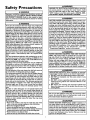
Owners
Manual
FOR POTABLEWATER
HEATING ONLY
NOT SUITABLE FOR
SPACEHEATING
Model
No.
153.318031
153.318131
27 GaL
40 Gal.
THE
ECONOMIZER
TM6
TABLE
TOP
ELECTRIC
WATER
HEATER
LISTED
Caution:
Read and Follow
• Safety Instructions
• Installation
• Operation
• Care and Maintenance
• Troubleshooting
• Parts List
GAMA certification applies to all residential electric water heaters with
capacities of 20 to 120 Gallons. Input rating of 12 Kw or lessat a voltage
no greater than 250
All Safety Rules and
Operating Instructions
Before First Use of
_WARNING
READ THE GENERAL SAFETY SECTION BEGINNING ON INSIDE COVER
AND THEN THIS ENTIRE HANUAL BEFORE INSTALLING OR OPERATING THIS WATER HEATER.
This Product.
Save this Manual for Future Reference.
Sears, Roebuck
Printed in the U.S.A. 1203
and Co., Hoffman
www.sears.com
Estates,
IL 60179
U.S.A.
Part No. 184733-000
Safety
AWARNING
Precautions
HAZARD
OF ELECTRICAL
SHOCK! Before removing
any access panels or servicing the water heater, make I
sure the electrical supply to the water heater is turned
"OFF". Failure to do this could result in DEATH, SERIOUS BOD LY NJURY, OR PROPERTY DAMAGE.
AWARNING
J
Improper installation, adjustment, alteration, service or
maintenancecan cause DEATH, SERIOUS BODILY INJURY,J
OR PROPERTY DAMAGE. Refer to this manual for assistance or consult your localSearsService Center for further
information.
AWARNING
HOTTER
WATER CAN SCALD: Water heaters are
intended to produce hot water. Water heated to a temperature which will satisfy space heating, clothes washing, dish
washing, and other sanitizing needs can scald and permanently injure you upon contact. Some people are more likely to be permanently injured by hot water than others.
These include the elderly, children, the infirm, or physically/mentally handicapped. If anyone using hot water in your
home fits into one of these groups or if there is a local code
or state law requiring a certain temperature water at the
hot water tap, then you must take special precautions. In
addition to using the lowest possible temperature setting
that satisfies your hot water needs, a means such as a mixing valve, shall be used at the hot water taps used by these
people or at the water heater. Mixing valves are available at
plumbing supply or hardware stores. Follow manufacturers
instructions for installation of the valves. Before changing
the factory
setting on the thermostat,
read the
"Temperature
Regulation" section in this manual.
AWARNING
At the time of manufacture thiswater heater was provided with
a combination temperature-pressures relief valve certified by a
nationally recognized testing laboratory that maintains periodic
inspection of production of listed equipment or materials, as
meeting the requirements for Relief Valvesand Automatic Gas
Shutoff Devicesfor Hot Water Supply Systems, andthe current
edition of ANSI Z21.22, CSA 4.4 and the code requirements of
ASME. If replaced, the valve must meet the requirements of
local codes, but not lessthan a combination temperature and
pressure relief valve certified as meeting the requirements for
Relief Valvesand Automatic Gas Shutoff Devicesfor Hot Water
Supply Systems, ANSI Z21.22, CSA 4.4 by a nationally recognized testing laboratory that maintains periodic inspection of
production of listed equipment or materials.
The valve must be marked with a maximum set pressure not to
exceed the marked hydrostatic working pressure of the water
heater (150 Ibs./sq. in.) and a discharge capacity not lessthan
the water heater input rate as shownon the model rating plate.
(Electric heaters - watts divided by 1000 x 3412 equal BTU/Hr.
rate.)
Your local jurisdictional authority, while mandating the use of a
temperature-pressure relief valve complying with ANSI Z21.22,
CSA 4.4 and ASME, may require a valve model different from
the one furnishedwith the water heater.
Compliance with such local requirements must be satisfied by
the installer or end user of the water heater with a locally prescribed temperature-pressure relief valve installed in the designated opening in the water heater in place of the factory furnished valve.
For safe operation of the water heater, the relief valve must not
be removed from it'sdesignatedopening or plugged.
The temperature-pressure relief valve must be installed directly
into the fitting of the water heater designated for the relief
valve. Positionthe valve downward and provide tubing so that
any dischargewill exit only within 6 inchesabove, or at any dis_
tance below the structural floor. Be certain that no contact is
made with any live electrical part. The dischargeopening must
not be blocked or reduced in size under any circumstances.
Excessivelength, over 30 feet, or use of more than four elbows
can cause restriction and reduce the discharge capacity of the
valve.
No valve or other obstruction is to be placed between the
relief valve and the tank. Do not connect tubing directly to
discharge drain unlessa 6" air gap is provided. To prevent bodily injury, hazard to life, or property damage, the relief valve
must be allowed to discharge water in quantities should circumstances demand. If the discharge pipe is not connected to
a drain or other suitable means, the water flow may cause
property damage.
The Discharge Pipe:
• Must not be smaller in size than the outlet pipe size of the
valve,or haveany reducing couplingsor other restrictions.
• Must not be pluggedor blocked.
• Must be of material listed for hot water distribution.
• Must be installed soas to allow complete drainage of both the
temperature-pressure relief valve,and the dischargepipe.
• Must terminate at an adequate drain.
• Must not haveany valve between the relief valve and tank.
AWARNING
WATER HEATERS EQUIPPED
FOR ONE VOLTAGE
ONLY: This water heater is equipped for one type voltage only. Check the rating plate near the bottom access
panel for the correct voltage. DO NOT use this water
heater with any voltage other than the one shown on the
model rating plate. Failure to use the correct voltage can
cause problems which can result in DEATH, SERIOUS
BODILY INJURY, OR PROPERTY DAMAGE. If you have
any questions or doubts consult your electric company.
AWARNING
INSULATING
JACKETS: When installing an external
water heater insulation jacket on an electric water heater:
a. DO NOT cover the temperature-pressure relief valve.
b. DO NOT put insulation over the access covers or any
access
areas.
c. DO NOT remove operating instructions, and safety
related warning labels and materials affixed to the
water heater.
d. DO obtain new warning and instruction labels from
Sears for placement on the jacket directly over the
existing labels.
AWARNING
Do not use this appliance if any part of it hasbeen under I
water. An electrical short or malfunction could occur.
The water heater sboud be rap aced.
A CAUTION
WATER HEATERS EVENTUALLY
LEAK: Installation of
the water heater must be accomplished in such a manner
that if the tank or any connections should leak, the flow of
water will not cause damage to the structure. When such
locations cannot be avoided, a suitable drain pan should be
installed under the water heater. Drain pans are available
at your local hardware store. Such a drain pan must be
piped to an adequate drain.
2
Table of Contents
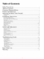
Safety Precautions ....................................................................................................
.2
Table of Contents ...............................................................................................
.3
Customer Responsibilities ................................................................................
.4
Product Spedfications
............................................................................................
.4
Materials and Basic Tools Needed ..................................................................
5
Materials Needed ......................................................................................................................................................................
Basic "lbols ................................................................................................................................................................................
Installation
Instructions
5
5
.........................................................................................
6-14
Removing the Old Water Heater. ............................................................................................................................................
Facts m Consider About the Location .....................................................................................................................................
Facts m Consider About the Convertible Element ...................................................................................................................
Water Piping ............................................................................................................................................................................
T&P Valve and Pipe Insulation ................................................................................................................................................
"l_mperature-Nessure
Relief Valve ............................................................................................................................................
Filling the Water Hearer ..........................................................................................................................................................
Converting the Element ...................................................................................................................................................
Wiring Diagram .....................................................................................................................................................................
Wiring ....................................................................................................................................................................................
Installation Checklist ..............................................................................................................................................................
N
.7
.7
.8
.8
_
10
10-12
12
13
14
Service and Adjustment ....................................................................................
15-19
_l_mperature Regulation ..........................................................................................................................................................
Thermostats ............................................................................................................................................................................
_l_mperature Settings ..............................................................................................................................................................
Thermostat Adjustment ..........................................................................................................................................................
_lhnperature Pressure Relief Valve Operation ..........................................................................................................................
Draining .................................................................................................................................................................................
Element Cleaning/Replacement
........................................................................................................................................
Anode Rod Inspection ............................................................................................................................................................
Drain Valve Washer Replacement ...........................................................................................................................................
Service ....................................................................................................................................................................................
Troubleshooting
Guide
..............................................................................................................
Start Up Conditions ..............................................................................................................................................................
Thermal Expansion ..............................................................................................................................................................
Strange Sounds ....................................................................................................................................................................
Operational Conditions .....................................................................................................................................................
Smelly Water ........................................................................................................................................................................
"Air" In Hot Water Faucets .................................................................................................................................................
Rumbling Noise ...................................................................................................................................................................
High "Ihnperature Shut Of}'System .................................................................................................................................
Not Enough or No Hot Water .............................................................................................................................................
Water Is *lbo Hot .................................................................................................................................................................
Leakage Checkpoints ...........................................................................................................................................................
15
15
15
15
16
16
16-19
19
19
19
20-23
20
.20
.20
21,22
.21
.21
.21
21,22
.22
.22
.23
Parts Order List ..................................................................................................
26,27
Warranty.. .............................................................................................................
28
3
Customer
Thank
Responsibilities
You
The installation must conform with the instructions in the
manual; electric company rules; and Local Codes, or in the
absence of Local Codes, with the current edition of the
National Electrical Code. This publication is available from
your local government or public library or electric company
or by writing Underwriters Laboratories, 333 Pfingsten Road,
Northbrook, IL 60062.
for purchasing
a Sears water heater.
Properly installed and maintained, it should give you years of"
trouble free service. If you should decide that you want the new
water heater professionally installed by Sears contact the local
Sears Service Center or any Sears store. They will arrange for
prompt, quality installation by Sears authorized contractors.
Abbreviations
Found
In This Instruction
U.L.-Underwriters
Laboratories
Inc., 333
Northbrook,
IL 60062
NEC - National Electrical Code
ANSI -American National Standards Institute
Manual
Pfingsten
If after reading this manual you have any questions or do not
understand any portion of the instructions, call Sears Service
Center.
Rd.,
Carefully plan the place where you are going to put the water
heater. Correct electrical wiring and connections are very
important in preventing death from possible electrical shock
and fires.
• Read the "Safety Precautions" section of this manual first and
then the entire manual carefully, lfyou don't follow the safety rules, the water heater will not operate properly. It could
cause DEATH, SERIOUS BODILY INJURY AND/OR
PROPERTY DAMAGE.
This manual contains instructions for the installation, operation, and maintenance of this electric water heater. It also
contains warnings throughout the manual that you must
read and be aware of. Allwarnings and all instructions are
essential to the proper operation of the water heater and your
safety. Since we cannot put everything on the first few pages,
READ THIS ENTIRE MANUAL BEFORE ATTEMPTING TO INSTALL OR OPERATE
THE WATER
HEATER.
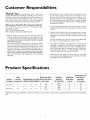
Product
MODEL
NUMBER
TANK
CAPACITY
IN GALLONS
Examine the location to ensure the water heater complies with
the "Facts to Consider About the Location" section.
For California installation this water heater must be braced,
anchored, or strapped to avoid falling or moving during an
earthquake. See instructions for correct installation procedures. Instructions may be obtained from your local dealer,
wholesaler, public utilities or California Office of the State
Architect, 400 P Street, Sacramento, CA 95814.
• Massachusetts Code requires this water heater to be installed
in accordance with Massachusetts 248-CMR 2.00: State
Plumbing Code and 248-CMR 5.00.
Specifications
RECOVERYRATE
DIMENSIONS IN INCHES GALS. PER HOUR
WIDTH DEPTH HEIGHT
@90°E RISE
153.318031
27
21"
25"
36"
153.318131
4O
24"
25"
36"
17.3
25.0
17.3
25.0
ELEMENT
WATTAGE
AT 240 VOLTS
3800
5500
3800
5500
MINIMUM
WIRE SIZE*
(GAUGE)
12
10
12
10
MAXIMUM FUSE
OR CIRCUIT
B_AKER
SIZE (AMPS)
20
30
20
30
*Wiring size based on standard 60°C. copper wire. If distance from fuse box to water heater is more than 90 feet, refer to your local electrical
code.
4
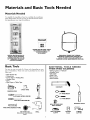
Materials
Materials
and Basic Tools Needed
Needed
_b simplify the installation Sears has available the installation
parts shown below. You may or may not need all of these materials, depending on your type of installation.
WATER HEATER HEAT TRAPS
HELP REDUCE HEAT LOSS
DUE TO THERMAL
SYPHONING
WATER HEATER INSTALLATION KIT WITH FLEXIBLE
CONNECTORS
FOR 3/4" OR
I/2" THREADED
OR SWEAT
COPPER PLUMBING
EXPANSION
TANKS FOR THERMAL
EXPANSION
CONDITIONS
AVAILABLE
IN
2 GALLON AND 5 GALLON CAPACITY
THROUGH
LOCAL SEARS SERVICE CENTERS
Basic Tools
You may or may not need all of these tools, depending on your
type of installation. These tools can be purchased at your local
Sears store.
Pipe Wrench (2)
Screwdriver
6 Foot Tapeor Folding Rule
Garden Hose
Drill
Pipe Dope or Teflon Tape
ADDITIONAL
WHEN
SWEAT
TOOLS
NEEDED
SOLDERING
Tubing Cutters or Hacksaw
Propane Torch
Soft Solder
Solder Flux
Emery Cloth
Wire Brushes
HACKSAW
6 FOOT TAPE
GARDEN
HOSE
3/4" WIRE BRUSH
SLOT-HEAD
SCREW
DRIVER
PIPE
WRENCH
j
PHILLIPS
1/2" WIRE BRUSH
SCREWDRIVER
PROPANE
TORCH
ROLL OF LEAD FREE
SOFT SOLDER
PIPE DOPE (SQUEEZE
TUBE)
_
roll of teflon tape
(Use only on water connections)
DRILL
ROLL OF EMERY
CLOTH
SOLDER
FLUX
TUBING
CUTTER
Installation
Instructions
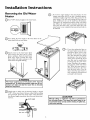
Removing the Old Water
Heater
Q_hrn
"OFF" electrical supply to the water heater.
Q
a. If you have copper piping to the water heater, the two
copper water pipes can be cut with a hacksaw approximately four inches away from where they connect to the
water heater. This willavoid cutting off"the pipes too
short. Additional cuts can be made later if necessary.
Disconnect the temperature-pressure relief valve drain
line. When the water heater is drained, disconnect the
hose from the drain valve. Close the drain valve.The
water heater is now completely disconnected and ready to
be removed.
Q'fhrn
"OFF" the water supply to the water heater at the
water shutoff"valve or water meter.
Qb.
a hose to the water heater drain
QAttach
valve and put the other end in a floor
drain or outdoors. Open the water heater
drain valve. Open a nearby hot water
faucet which will relieve pressure in the
water heater and speed draining.
_,WARNING
J
The water passing out of the drain valve may be
extremely hot. To avoidbeing scalded,make sure all connections are tight and that the water flow is directed
awayfrom any person.
Q
Check, again to make sure the electrical supply is turned
OFF to the water heater. Remove cabinet top by pulling
the top forward, all the way until it is free. Then disconnect
the electrical supply connection from the water heater junction box.
electric supply
-
wire
nuts
green
ground
screw
/
If you have galvanized pipe to
the water heater, loosen the two
galvanized pipes with a pipe
wrench at the union in each
line. Also disconnect the piping
remaining to the water heater.
These pieces should be saved
since they may be needed when
reconnecting
the new water
heater. Disconnect the temperature-pressure relief valve drain
line. When the water heater is
drained, disconnect the hose
from the drain valve. Close the
drain valve.The water heater is
now completely disconnected
and readyto be removed.
_, CAUTION
J
Mineral buildup or sediment may have accumulated in J
the old water heater. This causesthe water heater to be I
much heavier than normal and this residue, if spilledout,
could causestaining.
Installation
Instructions
(cont'd)
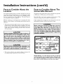
Facts to Consider About the
Location
Facts to Consider About The
Convertible Element
You should carefully choose an indoor location for the new
water heater, because the placement is a very important consideration for the safety of the occupants in the building and for
the most economical use of the appliance. This water heater is
not intended for outdoor installation.
The element of the water heater can be converted
at 3800 watts to 5500 watts on a 240 volt system.
Whether
replacing an old water heater or putting the water
heater in a new location, the following critical points must he
observed.
If after reading these instructions in this manual, if you do not
understand any portion, call the Sears Service Center.
• The location selected should be indoors as close to and as centralized with the water piping system as possible. This water
heater, as well as all water heaters, will eventually leak. Do not
install without adequate drainage provisions where water flow
will cause damage.
A CAUTION
WATER HEATERS EVENTUALLY
LEAK: Installation of
the water heater must be accomplished in such a manner that if the tank or any connections should leak, the
flow of water will not cause damage to the structure.
When such locations cannot be avoided, a suitable drain
pan should be installed under the water heater. Drain
pans are available at your local hardware store. Such a
drain pan must be piped to an adequate drain.
from operation
Read and follow water heater warnings and instructions. If this
manual is missing contact the retailer or manufacturer.
AWARNING
Before making the conversion to 5500 watts, check the
(I) power supply..must
be 240 volts, (2) wiring...10
gauge AWG, Type TW, 60°C or equivalent,
and (3)
Circuit breakers or fusing...capable of 30 amp loading.
Also, the installation must conform with this manual,
local codes and electric utility rules. Failure to comply
can result in DEATH, SERIOUS BODILY INJURY, OR
PROPERTY DAMAGE.
A CAUTION
INSTALLATION
IN RESIDENTIAL
GARAGES:
The I
water heater must be located andlor protected so it is
not subject to phys ca damage by a mov ng veh c e.
• The location selection must provide adequate clearances for
servicing and proper operation of the water heater.
NOTE: Whether or not the element conversion is made the
model rating plate must be marked. Using a hard point ink
pen, check the appropriate block within the model rating
plate, which is located adjacent to the lower access panel.
Installation
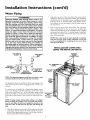
Water
Instructions
(cont'd)
Piping
Look at the top cover of the water heater. The water outlet is
marked hot. Put two or three turns of teflon tape around the
threaded end of the threaded-to-sweat coupling and around
both ends of the _" threaded nipple. Using flexible connectors, connect the hot water pipe to the hot water outlet on
the water heater.
*AWARNING
HOTTER
WATER CAN SCALD: Water heaters are
intended to produce hot water. Water heated to a temperature which will satisfy space heating, clothes washing, dish washing, and other sanitizing needs can scald
and permanently injure you upon contact. Some people
are more likely to be permanently injured by hot water
than others. These include the elderly, children, the
infirm, or physically/mentally
handicapped. If anyone
using hot water in your home fits into one of these
groups or if there is a local code or state law requiring a
certain temperature
water at the hot water tap, then
you must take special precautions. In addition to using
the lowest possible temperature
setting that satisfies
your hot water needs, a means such as a mixing valve,
shall be used at the hot water taps used by these people
or at the water heater. Mixing valves are available at
plumbing supply or hardware stores. Follow manufacturers instructions for installation of the valves. Before
changing the factory setting on the thermostat, read the
"Temperature
Regulation" section in this manual.
HOT WATER A
OUTLET
J
Look at the top cover of the water heater. The cold water
inlet is marked cold. Put two or three turns of teflon tape
around the threaded end of the threaded-to-sweat coupling
and around both ends of the _" threaded nipple. Using flexible connectors, connect the cold water pipe to the coldwater
inlet of the water heater.
NOTE: Your water heater is super insulated to minimize
heat loss from the tank. Further reduction in heat loss
can be accomplished by insulating the hot water lines
from the water heater.
INSTALLATION
COMPLETED
USING
THE INSTALLATION
FLEXIBLE
WATER
CONNECTORS
COLD WATER
NIPPLE
TEMPERED
WATEROU
*MIXING VALVE
FROM HOT
WATER OUTLET
ON WATER HEATER
ro COLD WATER
INLET ON
WATER HEATER
If a water heater is installed in a closed water supply system;
such as one having a back-flow preventer, check valve, water
meter with a check valve, etc...in the cold water supply; means
shall be provided to control thermal expansion. Contact the
local utility or Sears Service Center on how to control this situation.
NOTE: If using copper tubing, solder tubing to an adapter
before attaching the adaptor to the cold water inlet connection. Do not solder the cold water supply line directly to the
cold water inlet. It will harm the dip tube and damage the
tank.
•
_I_keoff the cabinet top to make all the water and electrical
connections. Pull the cabinet top forward, all the way until it
is free. xY./henreplacing the top, put it on the clips, almost to
the back, push down and then push back.
3/4"
"THREADED
NIPPLE
VALVE
_THREADED TO
' SWEAT COUPLING
NOTE: This piping arrangement would have to be done at some
convenient location away from the table top water heater.
The illustration shows the attachment of the water piping to the
water heater. The water heater is equipped with Yd'water connections.
KIT
INLET
WATER
LINE
DISCHARGE
_
PIPE
(Do not cap
or plug)
Installation
Instructions
(cont'd)
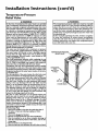
Temperature-Pressure
Relief Valve
_,WARNING
_,WARNING
At the time of manufacture this water heater was provided
with a combination temperature-pressures
relief valve certified by a nationally recognized testing laboratory that maintains periodic inspection of production of listed equipment
or materials, as meeting the requirements for Relief Valves
and Automatic Gas Shutoff Devices for Hot Water Supply
Systems, and the current edition of ANSI Z21.22, CSA 4.4
and the code requirements of ASME. If replaced, the valve
must meet the requirements
of local codes, but not less
than a combination temperature and pressure relief valve
certified as meeting the requirements for Relief Valves and
Automatic Gas Shutoff Devices for Hot Water Supply
Systems, ANSI Z21.22 • CSA 4.4 by a nationally recognized
testing laboratory that maintains periodic inspection of production of listed equipment or materials.
The valve must be marked with a maximum set pressure
not to exceed the marked hydrostatic working pressure of
the water heater (150 Ibsdsq. in.) and a discharge capacity
not less than the water heater input rate as shown on the
model rating plate. (Electric heaters - watts divided by 1000
x 3412 equal BTU/Hr. rate.)
Your local jurisdictional authority, while mandating the use
of a temperature-pressure relief valve complying with ANSI
Z21.22 • CSA 4.4 and ASME, may require a valve model different from the one furnished with the water heater.
Compliance with such local requirements must be satisfied
by the installer or end user of the water heater with a locally
prescribed temperature-pressure relief valve installed in the
designated opening in the water heater in place of the factory furnished valve.
For safe operation of the water heater, the relief valve must
not be removed from it's designated opening or plugged.
The temperature-pressure
relief valve must be installed
directly into the fitting of the water heater designated for
the relief valve. Position the valve downward and provide
tubing so that any discharge will exit only within 6 inches
above, or at any distance below the structural floor. Be certain that no contact is made with any live electrical part.
The discharge opening must not be blocked or reduced in
size under any circumstances. Excessive length, over 30 feet,
or use of more than four elbows can cause restriction and
reduce the discharge capacity of the valve.
No valve or other obstruction is to be placed between the
relief valve and the tank. Do not connect tubing directly to
discharge drain unless a 6" air gap is provided. To prevent
bodily injury, hazard to life, or property damage, the relief
valve must be allowed to discharge water in quantities
should circumstances demand. If the discharge pipe is not
connected to a drain or other suitable means, the water flow
may cause property damage.
The Discharge Pipe:
• Must not be smaller in size than the outlet pipe size of
the valve, or have any reducing couplings or other
restriction.
• Must not be plugged or blocked.
• Must be of material listed for hot water distribution.
• Must be installed so as to allow complete drainage of
both the temperature-pressure relief valve, and the discharge pipe.
• Must terminate at an adequate drain.
• Mustnothaveanyvalvebotweenthereliefvalveandtank.
The temperature-pressure
relief valve must be manually
operated at least once a year. Caution should be taken to
ensure that (I) no one is in front of or around the outlet
of the temperature-pressure
relief valve discharge line,
and (2) the water manually discharged will not cause any
bodily injury or property damage because the water may
be extremely hot.
If after manually operating the valve, it fails to completely reset and continues to release water, immediately,
close the cold water inlet to the water heater, follow the
draining instructions, and replace the temperature-pressure relief valve with a new one.
TEMPERATURE-PRESSURE
RELIEF VALVE
DISCHARGE
PIPE
(Do not cap
or plug)
6 ,f
AIR GAP
FLOOR DRAIN
9
Installation
Filling the Water
Instructions
(cont'd)
Heater
A CAUTION
J
Never usethis water heater unlessit is completely full of J
water. To prevent damage to the tank and heating ele- J
ment, the tank must be filled with water. Water must J
flow from the hot water faucet before turning "ON"
power.
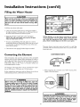
_lb fill the water heater with water:
, Close the water heater drain valve by turningthe handle to
the right (clockwise). The drain valve is on the lower front of
the water heater beneath the small access panel.
, Open the cold water supply valve to the water heater.
NOTE: The cold water supply valve must be left open
when the water heater is in use.
NOTE: Whether or not the element conversion is made the
model rating plate must be marked. Using a hard point ink
pen, check the appropriate block within the model rating
plate, which is located adjacent to the lower access panel.
• *lb insure complete filling of the tank, allow air to exit by
opening the nearest hot water faucet. Allow water to run until
a constant flow is obtained. This will let air out of the water
heater and the piping.
Necessary element conversion parts are located in a small bag
contained within the electrical junction box on top of the water
heater tank cover.
• Check all new water piping for leaks. Repair as needed.
Converting
CONVERSION
the Element
PARTS
These instructions only cover the conversion of the convertible
element, read this entire Manual before attempting to install or
operate the water heater. The water heater is factory set to operate at 3800 watts. The element can be converted to operate at
5500 watts. Refer to the "Facts to Consider About the
Convertible Element" section.
SCREW
BUSS BAR
The element of the water heater can be converted from operation at 3800 watts to 5500 watts on a 240 volt system.
1. Before beginning the conversion turn "OFF" electric power
supply tothe water heater.
If after reading these instructions and this Manual, if you do not
understand any portion, call the Sears Service Center.
AWARNING
Before making the conversion to 5500 watts, check the
(I) power supply...mustbe 240 volts, (2) wiring...10 gauge
AWG, Type TW, 60°C or equivalent, and (3) Circuit
breakers or fusing...capableof 30 amp loading. Also, the
installation must conform with this Manual, local codes
and electric utility rules. Failure to comply can result in
DEATH, SERIOUS BODILY INJURY OR PROPERTY
DAMAGE.
AWARNING
HAZARD OF ELECTRICAL
SHOCK! Before removing
any access panels or servicing the water heater, make
sure the electrical supply to the water heater is turned
"OFF". Failure to do this could result in DEATH, SERIOUS BODILY INJURY, OR PROPERTY DAMAGE.
10
Installation
Converting
(cont'd)
Instructions
(cont'd)
the Element
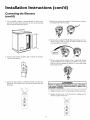
5. Remove the screws from terminal 2 of the element, and move
the looped end of the wire aside.
2. The convertible element is located behind the large access
panel of the water heater. Remove the two screws securing
the access panel, and remove panel.
6. The buss bar is labeled 5500 W. Place the buss bar over terminals 2 and 3 with the 5500 W visible. Install the extra
screw provided into terminal 3.
3. Remove tape and the insulation pad to expose the terminal
cover over the element.
7. The wire removed from terminal 2 has a looped end. It must
remain looped and now be placed (as shown) on top of the
buss bar, over the opening of terminal 2, and secured using
the remaining screw.
I O
@
nJn_r
pcoo_
B_FC_E
SE_WO:N¢
------I
4. Lift out the tab as shown to unclip the terminal cover from the
thermostat. The terminal cover can now be removed from the
thermostat.
_,WARNING
I
Failure to tighten terminal screwscan causea fire which
can result in DEATH, SERIOUS BODILY INJURY, OR
PROPERTY DAMAGE.
8. _l]ghten terminals 2 and 3 to ensure proper electricalconnection.
9. Replace terminal cover on the thermostat, making sure the
notch is in place over the tab.
11
Installation
Converting
(cont'd)
Instructions
(cont'd)
the Element
12. Complete wiring to water heater, or if completed, turn
"ON" electric power to water heater after filling tank with
water.
_,WARNING
J
Make sure the thermostat is flush against the tank, the
terminal cover is in place, and the insulation is replaced. I
Failure to do so can result in DEATH, SERIOUS BODILY
NJURY,OR PROPERTY DAMAGE.
1
10. Replace the insulation pad and tape on so that it completely
covers the thermostat and element.
A CAUTION
Never use this water heater unless it is completely full of
water. To prevent damage to the tank and heating element, the tank must be filled with water. Water must
flow from the hot water faucet before turning "ON"
power.
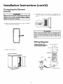
Wiring
Diagram
STANDARD WIRING FOR
2 WIRE LEAD WATER HEATERS
240 VOLT SINGLE ELEMENT
TO ELECTRIC POWER SUPPLY
11. Replace the access panel.
RED
LOWER HI-TEHP
LiMiT SWITCH
LOWER HEATING ELEMENT
_OR3_OWA_S
12
Installation
Instructions
(cont'd)
Wiring
CAUTION
3. If metal conduit is used for the grounding conductor:
J
Never usethis water heater unlessit is completely full of J
water. To prevent damage to the tank and heating element, the tank must be filled with water. Water must
flow from the hot water faucet before turn ng on power.
a.
The grounding electrode conductor shall be of copper,
aluminum, or copperclad aluminum. The material shall
be of one continuous length without a splice or joint.
B. Rigid metal conduit, intermediate metal conduit, or electrical metallic tubing may be used for the grounding
means if conduit or tubing is terminated in f]ttings
approved for grounding.
You must provide all wiring of the proper size outside of the
water heater. You must obey local codes and electric company
requirements when you install this wiring.
C.
If you are not familiar with electric codes and practices, or if you
have any doubt, even the slightest doubt, in your ability to connect the wiring to this water heater, obtain the service of a competent electrician. Contact your Sears salesperson to arrange for
a professional electrician.
Flexible metal conduit or flexible metallic tubing shall be
permitted for grounding if all the following conditions
are met:
1. The length in any ground return path does not exceed
6 feet.
2. The circuit conductors contained therein are protected
by overcurrent devices rated at 20 amperes or less.
3. The conduit or tubing
approved for grounding.
_,WARNING
WATER HEATERS EQUIPPED FOR ONE VOLTAGE
ONLY: This water heater is equipped for one type voltage only. Check the rating plate near the bottom access
panel for the correct voltage. DO NOT use this water
heater with any voltage other than the one shown on the
model rating plate. Failure to usethe correct voltage can
cause problems which can result in DEATH, SERIOUS
BODILY INJURY,OR PROPERTY DAMAGE. If you have
any questionsor doubts consult your electric company.
is terminated
in fittings
For complete grounding details and all allowable exceptions,
refer to the current edition of the National Electrical Code,
NFPA 70.
4.
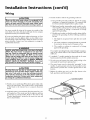
A standard _" conduit opening has been made in the water
heater junction box for the conduit connection.
5. Use wire nuts and connect the power supply wiring to the
wires inside the water heater's junction box.
6. The water heater must be electrically "grounded" by the
installer. A green ground screw has been provided on the
water heater's junction box. Connect ground wire to this
location.
_t,CAUTION
If wiring from your fuse box or circuit breaker box was
aluminum for your old water heater, replace it with copper wire. If you wish to reuse the existing aluminum
wire, havethe connection at the water heater made by a
competent electrician. Contact your Sears salesperson
to arrange for a professionalelectrician.
7. Replace the cabinet top, put it on the clips, almost to the
back, push down and then push back.
ELECTRIC
SUPPLY
1. Provide a way to easily shut off the electric power when working on the water heater. This could be with a circuit breaker
or fuse block in the entrance box or a separate disconnect
switch.
:LAMP
2. Install and connect a circuit directly from the main fuse or circuit breaker box. This circuit must be the right size and have
its own fuse or circuit breaker. Refer to the chart in the
"Product Specifications" section for the correct size wire and
fuse or circuit breaker.
WIRE CONNECTORS
GREEN GROUND
SCREW
13
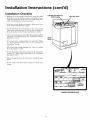
Installation
Installation
Instructions
(cont'd)
Checklist
TEMPERATURE-PRESSURE
• Whether or not the element conversion is made, the model
rating plate must be marked• Using a hard point ink pen,
check the appropriate block within the model rating plate,
which is located adjacent to the access panel.
SHUT-OFF VALVE
• ls the fuse or circuit breaker size correct as shown in the chart
in the "Product Specifications" section?
• Are the wires from the circuit breaker or fuse service to the
water heater's junction box on the correct wire size (gauge) as
shown in the chart in the "Product Specifications" section?
• ls the new temperature-pressure relief valve properly installed,
and piped to an adequate drain? See "'I_mperature-Pressure
Relief Valve" section•
DRAIN
• ls the water heater completely filled with water? See "Filling
the Water Heater" instructions
in the "Installation
Instructions
section.
• Will a water leak damage anything? See "Facts to Consider
About the Location" section.
• Are the cold and hot water lines connected to the water heater
correctly? See "Water Piping" instructions in the "Installation
lnstrucnons section.
• ls there adequate clearance for maintenance around the water
heater?
• Do you need to call your electric company to check your
wiring?
MODEL
14
RATING
PLATE
Service
Temperature
and Adjustment
Regulation
Temperature
AWARNING
HOT-
HOTTER
WATER CAN SCALD: Water heaters are
intended to produce hot water. Water heated to a temperature which will satisfy space heating, clothes washing, dish washing, and other sanitizing needs can scald
and permanently injure you upon contact. Some people
are more likely to be permanently injured by hot water
than others. These include the elderly, children, the
infirm, or physically/mentally
handicapped. If anyone
using hot water in your home fits into one of these
groups or if there is a local code or state law requiring a
certain temperature
water at the hot water tap, then
you must take special precautions. In addition to using
the lowest possible temperature
setting that satisfies
your hot water needs, a means such as a mixing valve,
shall be used at the hot water taps used by these people
or at the water heater. Mixing valves are available at
plumbing supply or hardware stores. Follow manufacturers instructions for installation of the valves. Before
changing the factory setting on the thermostat, read the
"Temperature
Regulation" section in this manual.
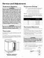
Settings
ls a thermOStat setting of approximately 120°F, whi& will
supply hot water at the most economical temperatures.
A-Is a thermostat setting of approximately 130°E
B-Is a thermostat setting of approximately 140°E
C-Is a thermostat setting of approximately 150°E
VERY HOT-
Is a thermostat setting of approximately 160°E It is recommended that the dial be set lower whenever possible.
NOTE: Water temperature range of 120°--140°F
most dishwasher manufacturers.
t60°F
About
150°F
About
140°F
AWARNING
J
Never allow small children to use a hot water tap, or to J
draw their own bath water. Never leave a child or handicapped personunattended n a bathtub or shower.
recommended
1/2 seconds
I - 112seconds
Less than S seconds
130°F
About 30 seconds
120°F
Hore than S minutes
Thermostat
by
Adjustment
The thermostat iias been factory set at hot (approximately 120°F) m reduce
the risk of scald injury.
Thermostats
The thermostat is adjustable if a different water temperature isdesired. Read
all warnings in the "'I_mperature-Reguladod' section before proceeding.
The thermostat of this water heater has been factory set at the
lowest position which approximates 120°F (Hot) to reduce the
risk of scald injury.
The thermostat pointer casl be turned dodavise (_,._ J) to increase the
temperature setting or counter clockwise (M- j_ ) to_'ecrease the temperature setting, with a small flat tip screwdriverT1. _Ihrn"OFF" the electrical power ro the water heater at the junction box.
The thermostat is factory set at its lowest position which approximates 120°F (Hot) and is adjustable ifa different water temperature is desired. Read all warnings in this manual and on the
water heater before proceeding.
AWARNING
I
HAZARD OF ELECTRICAL SHOCK! Before removing
any accesspanelsor servicingthe water heater, make sure I
the electrical supplyto the water heater is turned "OFF". I
Failure to do this could result in DEATH, SERIOUS BODILY NJURY,OR PROPERTY DAMAGE.
2. "hke offthe accesspanel and insulation pad.
3. The slotted ad ustment (using the screwdriver) can be turned clockwise (_..._J)
to increase the temperature setting, or counter c ockwise (M..._..._) to decrease the temperature setting.
4. Replace the insulation pad and access panel.
5. "lhrn "ON" the power supply.
ADJUSTMENT
ACCESS
ADJUSTABLE
THERMOSTAT
BEHIND
ACCESS PANEL
15
Service
and Adjustment
Temperature-Pressure
Valve Operation
Relief
The temperature-pressure
relief valve must
ually operated at least once a year.
TEM PERATURE-PRESSU
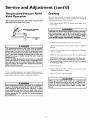
Draining
The water heater should be drained if being shut down during
freezing temperatures. Also periodic draining and cleaning of
sediment from the tank may be necessary.
be man-
• Before beginning turn "OFF" the electric power supply to the
water heater.
RE
AWARNING
I
HAZARD OF ELECTRICAL SHOCK! Before removing
any access panels or servicing the water heater, make I
sure the electrical supply to the water heater is turned
"OFF". Failure to do this could result in DEATH, SERIOUS BOD LY NJURY,OR PROPERTY DAMAGE.
ELIEF VALVE
L11I D,SCH,aG,
!1
(cont'd)
P'P
• CLOSE the cold water inlet valve to the water heater.
• OPEN a nearby hot water faucet and leave open to allow for
draining.
AWARNING
The temperature-pressure relief valve must be manually
operated at least once a year. Caution shouldbe taken to
ensure that (I) no one is in front of or around the outlet
of the temperature-pressure relief valve discharge line,
and (2) the water manually dischargedwill not causeany
property damage or bodily injury. The water may be
extremely hot.
If after manually operating the valve, it fails to completely
reset and continues to release water, immediately close
the cold water inlet to the water heater,follow the draining instructions, and replace the temperature-pressure
relief valvewith a new one.
• Connect a hose to the drain valve and terminate to an adequate
drain or outdoors.
• OPEN the water heater drain valve to allow for tank draining.
NOTE: If the water heater is going to be shut down and
drained for an extended period, the drain valve should be
left open with hose connected allowing water to terminate
to an adequate drain.
• Close the drain valve.
• Follow "Filling the Water Heater"
"Installation Instructions" section.
Failure to install and maintain a new properly listed temperaturepressure relief valve will release the manufacturer from any claim
which might result from excessivetemperature or pressure.
instructions
in the
• "Ihrn "ON" power to the water heater.
A CAUTION
I
Never use this water heater unless it is completely full I
water. To prevent damage to the tank and heating ele- I
ment, the tank must be filled with water. Water must I
flow from the hot water faucet before turning "ON"
power.
AWARNING
If the temperature-pressure relief valve on the appliance
weepsor dischargesperiodically,this may be due to thermal expansion. Your water heater may have a check
valve installed in the water line or a water meter with a
check valve. Consult your local Sears Service Center for
further information. Do not plug the temperature-pressure relief valve.
16
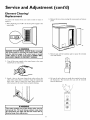
Service
and Adjustment
(cont'd)
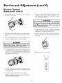
Element Cleaning/
Replacement
4. Remove the two screws securing the access panel, and remove
panel.
"Ib remove the element from your tank in order to clean or
replace it:
1. Before beginning turn "OFF" the electric power supply to the
water heater.
I
-
%
_,WARNING
I
HAZARD OF ELECTRICAL SHOCK! Before removing
any access panels or servicing the water heater, make I
sure the electrical supply to the water heater is turned
"OFF". Failure to do this could result in DEATH, SERIOUS BOD LY NJURY,OR PROPERTY DAMAGE.
5. Remove tape and the insulation pad to expose the terminal
cover and element.
O
2. "Iiirn off"the water supply to the water heater at the water
shutoff'valve or water meter.
_E_C_E
3. Attach a hose to the water heater drain valve and put the
other end in a floor drain or outdoors. Open the water heater
drain valve. Open a nearby hot water faucet which will
relieve pressure in the water heater and speed draining.
6. Lift out the tab a_sshown to unclip the terminal cover from
the thermostat. The terminal cover can now be removed
from the thermostat.
_,WARNING
I
The water passing out of the drain valve may be
extremely hot. To avoid being scalded, make sure
all connections are tight and that the water flow is
d rected away from any person.
L_
17
Service
and Adjustment
(cont'd)
Element Cleaning/
Replacement
(cont'd)
7. Disconnect the two wires on the element and unscrew the
old element from the tank.
13. _lb insure complete filling of the tank, allow air to exit by
opening the nearest hot water faucet. Allow water to run
until a constant flow is obtained. This will let air out of the
water heater and the piping.
A CAUTION
J
Never use this water heater unless it is completely J
full of water. To prevent damage to the tank and J
heating element, the tank must be filled with J
water. Water must flow from the hot water faucet
before turn ng ' ON ' power.
14. Check element for water leaks. If leakage occurs, tighten
element or repeat steps 2 and 3, remove element and reposition gasket. Then repeat steps 10 through 14.
8. Clean the area around the element opening. Remove any
sediment from or around the element opening and inside the
tank.
15. Reconnect the two wires to the element and then check to
make sure the thermostat remains firmly against the surface
of the tank.
9. If you are cleaning the element you have removed, do so by
scraping or soaking in vinegar or a de-liming solution.
AWARNING
J
Replacement elements must (I) be the same volt- J
age and (2) no greater wattage than listed on the
mode rat ng p ate affixed to the water heater.
10. A new gasket should be used in all cases to prevent a possible water leak. (See Element Gasket in the Repair Parts
Chart). Place the new element gasket on the thread side of
the cleaned or new element and screw into tank, securing
tightly using an element wrench.
16. Replace terminal cover on thermostat.
s_lcz_
11. Close the water heater drain valve by turning the handle to
the right (clockwise). The drain valve is on the lower front
of the water heater.
12. Open the cold water supply valve to the water heater.
NOTE: The cold water supply valve must be left open
when the water heater is in use.
18
Service
and Adjustment
(cont'd)
Element Cleaning/
Replacement
(cont'd)
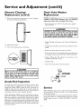
Drain Valve Washer
Replacement
17. Replace the insulation pad and tape on so that it completely covers the thermostat and element.
NOTE: For replacement, use a _2" x _¾_"x g_" thick washer
available at your nearest hardware store. For ordering a
replacement washer, refer to the Repair Parts section.
• Before beginning turn "OFF" the electrical power supply to
the water heater.
AWARNING
HAZARD OF ELECTRICAL SHOCK! Before removing
any access panels or servicing the water heater, make
sure the electrical supply to the water heater is turned
"OFF". Failure to do this could result in DEATH, SERIOUS BODILY INJURY,OR PROPERTY DAMAGE.
• Follow "Draining" instructions in the "Service andAdjustment"
section.
18. Replace access panel.
• "[iirning counter clockwise, remove the hex cap below the screw
handle.
19. "[hrn "ON" electric power to water heater.
I
I
• Remove the washer and put the new one in place.
• Screw the handle and cap assembly back into the drain valve
and retighten using a wrench. DO NOT OVER TIGHTEN.
• Follow "Filling the Water Heater"
"Installation Instructions" section.
instructions
in the
• Check for leaks.
• "[hrn "ON" electric power to the water heater.
A CAUTION
I
Never use this water heater unless it is completely I
full of water. To prevent damage to the tank and I
heating element, the tank must be filled with I
water. Water must flow from the hot water faucet
before turn ng ' ON ' power.
Anode
_HANDLE
AND
CAP ASSEMBLY
WASHER
Rod Inspection
The anode rod is used to protect the tank from corrosion. Most
hot water tanks are equipped with an anode rod. The submerged rod sacrifices itself to protect the tank. Instead of corroding the tank, water ions attack and eat away the anode rod.
"['his does not affect the water's taste or color. "['he rod must be
maintained to keep the tank in operating condition.
Service
Before calling for repair service, read the Start Up Conditions
and Operational Conditions found in the Troubleshooting
Guide of this manual.
If a condition persists or you are uncertain about the operation
of the water heater, let a qualified person check it out. Contact
SEARS Repair Services at 1-800-4-MY-HOME
(1-800-4694663).
Anode deterioration depends on water conductivity, not necessarily water condition. A corroded or pitted anode rod indicates
high water conductivity and should be checked and/or replaced
more often than an anode rod that appears to be intact.
Replacement of a depleted anode rod can extend the life of your
water heater. Inspection should be conducted by a Sears service
technician, and at a minimum should be checked annually after
the warranty period.
19
Troubleshooting
Guide
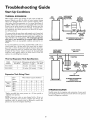
Start Up Conditions
THERMAL
EXPANSION
WATER HEATER
COLD - COLD WATER
HOT
Water supply systems may, because of such events as high line
pressure, frequent cut-of_, the effects of water hammer among
others, have installed devices such as pressure reducing valves,
check valves, back flow preventers, etc._to control these types of
problems. When these devices are not equipped with an internal
by-pass, and no other measures are taken, the devices cause the
water system to be dosed. As water is heated, it expands (thermal expansion) and dosed systems do not allow for the expansion of heated water.
(3)
PRESSURE
REDUCING
VALVEWITH
BY-PASS
, INLET FITTING
(0
EXPANSION
TANK
(z)
The water within the water heater tank expands as it is heated and
increases the pressure of the water system. If the relieving point of
the water heater's temperature-pressure
relief valve is reached, the
valve will relieve the excess pressure. The temperature-pressure
relief valve is not intended for the constant relief of thermal
expansion. This is an unacceptable condition and must be corrected.
PRESSUREGAUGE
RECOMMENDED INSTALLATION
(VERTICAL MOUNTING)
It is recommended that any devices installed which could create a
closed system have a by-pass and/or the system have an expansion tank to relieve the pressure built by thermal expansion.
Thermal expansion tanks are available from Sears stores and
through the Sears Service Centers. Contact the local plumbing
inspector, water supplier and/or the Sears Service Center for
assistance in controlling these situations.
Expansion
Model
Number
153.331020
_hnk Capacity
In Gallons
2
153.331050
5
Expansion
Expansion
"lank
Capacity
Needed
Tank
Inlet*
Water
Pressure
40psi
50psi
60psi
70psi
80psi
Tank
COLD
11 inches 14Y4inches
(3)
INLET COLD
WATER
SHUTOFF
EXPANSION
TANK
Chart
30
2
2
2
2
2
PRESSURE
REDUCING
VALVEWITH
BY-PASS
(0
Yi' Male
PRESSUREGAUGE
Water Heater Capacity (Gallons)
27
2
2
2
2
2
STRAPPING
Specifications
Dimensions in Inches Pipe Fitting
Diameter
Length
On "Ihnk
8 inches 12Y4inches Yi' Male
Sizing
FLOOR, CEILING
JOIST, ETC.
WATER HEATER
COLD WATER
INLET FITTING
HOT
Thermal
WATER
SHUTOFF
40
2
2
2
2
5
50
2
2
5
5
5
ALTERNATE RECOMMENDED
INSTALLATION
(HORIZONTAL MOUNTING)
66
5
5
5
5
5
STRANGE
SOUNDS
Possible noises due to expansion and contraction of some metal
parts during periods of heat-up and cool-down do not represent
harmful or dangerous conditions.
*Highest recorded inlet water pressure in a 24 hour period or
regulated water pressure.
NOTE= Expansion tanks are pre-charged with a 40 psi air
charge. If the inlet water pressure is higher than 40 psi, the
expansion tank's air pressure must be adjusted to match that
pressure, but must not be higher than 80 psi.
20
Troubleshooting
Operational
SMELLY
Guide
(cont'd)
Conditions
WATER
RUMBLING
In each water heater there is installed at least on anode rod (see
parts section) for corrosion protection of the tank. Certain water
conditions will cause a reaction between this rod and the water.
The most common complaint associated with the anode rod is
one of a "rotten egg smell". This odor is derived from hydrogen
sulfide gas dissolved in the water. The smell is the result of _bur
factors which must all be present for the odor to develop:
• a concentration of sulfate in the supply water.
• little or no dissolved oxygen in the water.
• a sulfate reducing bacteria within the water heater. (This
harmless bacteria is non-toxic to humans.)
• an excess of active hydrogen in the tank. This is caused by the
corrosion protective action of the anode.
NOISE
In some water areas, scale or mineral deposits will build up on
your heating elements. This buildup will cause a rumbling noise.
Follow "Element Cleaning/Replacement" instructions to clean
and replace the elements.
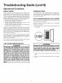
HIGH
TEMPERATURE
SHUT
OFF
SYSTEM
Your water heater has a high limit shut off system with a reset
button located on the thermostat.
Follow the resetting instructions which refer to the high limit
behind the access panel.
1. Before beginning, turn "OFF" electrical power supply to the
water heater.
Smelly water may be eliminated or reduced in some water heater
models by replacing the anode(s) with one of less active material,
and then chlorinating the water heater tank and all hot water
lines. Contact your local Sears Service Center for further information concerning an Anode Replacement Kit #9001453 and
this Chlorination _l_eatment.
If the smelly water persists after the anode replacement and chlorination treatment, we can only suggest that continuous chlorination and filtering conditioning equipment be considered to
eliminate the water problem.
Do not remove the anode leaving the tank unprotected. By doing
so, all warranty on the water heater tank is voided.
"AIR"
IN
HOT
WATER
%
FAUCETS
_,WARNING
I
HAZARD OF ELECTRICAL SHOCK! Before removing
any access panels or servicing the water heater, make I
sure the electrical supply to the water heater is turned
"OFF". Failure to do this could result in DEATH, SERIOUS BOD LY NJURY,OR PROPERTY DAMAGE.
_,WARNING
HYDROGEN
GAS: Hydrogen gas can be produced
in a hot water system that has not been used for a
long period of time (generally
two weeks or more).
Hydrogen
gas is extremely
flammable
and explosive. To prevent the possibility of injury under these
conditions, we recommend
the hot water faucet be
opened
for several minutes
at the kitchen
sink
before any electrical appliances which are connected to the hot water
system are used (such as a
dishwasher or washing machine).
If hydrogen gas is
present, there will probably
be an unusual sound
similar to air escaping through the pipe as the hot
water faucet is opened. There must be no smoking
or open flame near the faucet at the time it is
open.
2. Remove the two screws securing the access panel and remove
panel.
3. Remove the tape and insulation pad to expose the terminal
cover.
21
Troubleshooting
HIGH
TEMPERATURE
SHUT
OFF
Guide
(cont'd)
NOT
SYSTEM
(cont'd)
ENOUGH
OR
NO
HOT
WATER
• In a new installation, the water heater may not be properly
connected. Make sure the cold water supply valve is open.
Review and check piping installation. Make sure that the
cold water line is connected to the cold water inlet to the
water heater and the hot water line to the hot water outlet on
the water heater.
4. Reset the high limit by pushing in the red button marked
"RESET".
• Make sure the electrical supply to your water heater is "ON".
BUTTON
-_
• Check for loose or blown fuses in your water heater circuit.
Circuit breakers weaken with age and may not handle their
rated load and should be replaced.
• Make certain the disconnect switch, if used, is in the "ON"
position.
BESET
• Check to see the electric service to your house has not been
interrupted. If this is the case, contact the electric company.
• ls the thermostat set to the desired
"_mperature Regulation" section.
temperature?
See
• lfyou had experienced very hot water and now no hot water,
the problem may be due to the high temperature shut off"system.
See
High Tm_lperature
Shut Off System
in the
"Ii-oubleshooting section.
5. Replace the insulation pad and tape on so that it completely
covers the thermostat and element.
6. Replace the access panel.
7. Turn "ON" electric power to the water heater.
• During very cold weather, the incoming water will also be
colder and it will require a longer time to become heated.
• The hot water usage may exceed the capacity of the water
heater. If so, wait for water heater to recover after abnormal
demand. Also examine pipes and faucets for possible water leaks.
If the high limit must be reset again, call Sears
find out why the high limit
J Service Department_, to
CAUTION
turned "OFF" the electric power.
• If you can not determine the problem, then call the Sears
Service Department.
WATER
IS TOO
HOT
Adjust the thermostat to a lower setting. See the "_hnperature
Regulation" section.
22
Troubleshooting
Guide
(cont'd)
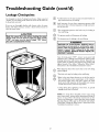
Leakage Checkpoints
/'7",
k._
Use this guide to check a "Leaking" water heater. Many suspected
"Leakers'are not leaking tanks. Often the source of the water can
be found and corrected.
®
If you are not thoroughly familiar with electric codes, the water
heater,
and safety practices, contact a Sears Service
Center
to
check the water heater.
CAUTION
*Condensation may be seen on pipes in humid weather or
pipe connections may be leaking.
Small amounts of water from temperature-pressure relief
valve may be due to thermal expansion or high water pressure in your area.
© *The
temperature-pressure relief valve may be leaking at
the tank fitting.
@ The primary anode rod fitting may be leaking.
® The elements may be leaking at the tank fitting.
J
Read this manual first, then before checking the water I
heater make sure the electric supply has been turned J
"OFF", and never turn the electric supply "ON" before
the tank iscompletely full of water.
AWARNING
HAZARD OF ELECTRICAL
SHOCK! Before
removing any accesspanels or servicingthe water
heater, make sure the electrical supplyto the water
heater is turned "OFF". Failure to do this could
result in DEATH, SERIOUS BODILY INJURY, OR
PROPERTY DAMAGE.
Turn electrical power "OFF", remove access panel and
insulation pad. If leaking around elements, follow proper
draining instructions and remove element. Reposition or
replace gasket on element. Place element into opening and
tighten securely. Then follow "Filling the Water Heater"
instructions in the "Installation Instructions" section.
®
Water from the drain valve may be due to the valve being
opened slightly.
©
®
*The drain valve may be leaking at the tank fitting.
*Water in the water heater bottom or on the floor may be
from condensation, loose connections or the temperature-pressure relief valve. DO NOT replace the water
heater until a full inspection of all possible water sources
is made and necessary corrective steps taken.
Leakage from other appliances, water lines, or ground
seepage should also be checked.
NOTE: _lb check where threaded portion enters tank,
insert cotton swab between jacket opening and fitting. If
cotton is wet, follow "Draining" instructions in the
"Service and Adjustment" section and then remove fitting.
Put pipe dope or teflon tape on the threads and replace.
Then follow "Filling the Water Heater" instructions in the
"Installation Instructions" section.
23
Notes
24
Notes
25
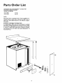
Parts Order
List
KENMORE THE ECONOMIZER _ 6 TABLE TOP
ELECTRIC WATER HEATERS
MODEL NUMBERS:
153.318031
153.318131
27 Gal.
40 Gal.
NOTE:
This water heater is equipped with a factory installed convertible element, which can be operated at 3800 watts or
5500 watts. Convertible elements are not offered as replacement parts.
ELEMENT ORDERING INFORMATION
If a replacement 3800 watt, 240 volt element is needed,
order Super Limeguard replacement element Item 42 31906.
If, at the time of instaUation, the water heater was converted
to operate at 5500 watts, order Super Limeguard replacement element Item 42 31908. (See model rating plate "If
Converted" box).
6
13
5
8
26
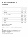
Parts Order
List (cont'd)
KENMORE THE ECONOMIZER ,a 6 TABLE TOP
ELECTRIC WATER HEATERS
MODEL NUMBERS:
153.318031
153.318131
27 Gal.
40 GaL
Model Numbers
153.318031
KEY
NO.
PART DESCRIPTION
153.318131
PART NUMBERS
1
Porcelain "Ibp
9000335
9000336
2
"I_mperature-Pressure Relief Valve
9000071
9000071
3
4
5
6
Dip "lhbe
Primary Anode Rod
Access Panel
Element Gasket
9001598
9001598
9001822
9001822
9000320
9000320
7
Element*
(See NOTE on page 26)
9000308
9000308
3800Watt
3800Watt
42 31906
42 31906
5500Watt
5500Watt
42 31908
42 31908
8
Buss Bar
9001591
9001591
9
10
Thermostat Bracket
Thermostat w/Hi Limit*
9000309
9000309
42 31918
42 31918
11
"I_rminal Cover
9002303
9002303
12
Drain Door
9000387
9000387
13
Drain Valve
9002402
9002402
14
Drain Valve Washer ('7_2"x _" x _" thick)**
9001584
9001584
15
16
#
Model Rating Plate "_
"IbePanel
Manual
0270104
0270104
9000338
000338
184733-000
* These parts are also available at most Sears retail stores.
**Also available at most hardware stores.
"_Replaced only on return of damaged plate.
# Not Illustrated
Now that you have purchased this water heater, should a need ever exist for repair parts or service, simply contact any SEARS Service
Center or call 1-800-4-MY-HOME (1-800-469-4663). Be sure to provide all pertinent facts when you call or visit.
All parts listed may be ordered from any SEARS Service Center, most Sears stores and by calling 1-800-366-PART (1-800-366-7278).
If the parts you need are not stocked locally, your order will be electronically transmitted to a SEARS Repair Parts Distribution Center for
handling.
The model number of the water heater will be found on the model rating plate located on the toe panel.
WHEN ORDERING
MODEL NUMBER
SERIAL NUMBER
REPAIR PARTS, ALWAYSGIVE THE FOLLOWING INFORMATION:
PART DESCRIPTION
PART NUMBER
THIS IS A REPAIR PARTS LIST, NOT A PACKING LIST.
27
FULL ONE YF_R WARRANTY
ON WATER HEKFER
For one year from the date of purchase, when your Sears Kenmore water heater is installed
residence in accordance with the instructions in this manual, Sears will:
and operated
in a single-family
1. Repair defects in material or workmanship
in this water heater, free of charge.
2. Furnish and install a new current model water heater of equal capacity and quality, free of charge, ifa leak occurs in the tank.
LIMITEDWARIb_N'ITON "[ANKSTHAT LEAK
After one year and through
the tank, Sears will furnish
installation.
6 years from the date of purchase for a water heater used in a single-family residence, ifa leak occurs in
a new current model water heater of equal capacity and quality. You will be charged for any
if the water heater is subjected to commercial, institutional,
industrial or use in residences
warranty coverage for tanks that leak is effective for 2 years from the date of purchase.
"Ib obtain warranty service, SIMPLY CALL 1-800-4-MY-HOME ®(1-800-469-4663).
product is in use in the United States.
"]['hiswarranty
of two families or more, the above
This warranty applies only while this
gives you specific legal rights and you may also have other rights which vary from state to state.
SEARS, ROEBUCK
AND CO., Dept. 817 WA, HOFFMAN
ES'I'ATES, 1L 6(1179
The price of your water heater does not include a free checkup service call. On water heater installations arranged by Sears, Searswarrants the installation.
A charge will be made on service calls due to poor or incomplete installation. These include:
a. Adjusting thermostat
b. Leaks in pipes or fittings
c. Condensation
MASTER PROTECTION
AGREEMENTS
• Fast help by phone - phone support from a Sears technician on
products requiring in-home repair, plus convenient repair s&eduling.
Congratulationson making a smart purchase.Yorenew Kenmor4_product is designedand manufactured foryearsof dependableoperation. But
llke all products, it may require preventivemaintenance or repair from
time to time. That's whenhaving a Master Protection Agreement can
saveyou money and aggravation.
• Power surge protection against electrical damage due to power fluctuations.
• Rental reimbursement
than promised.
Purchasea Master ProtectionAgreement now and protect yourselffrom
unexpectedhassleand expense.
if repair of your covered product takes longer
Once you purchase the Agreement,a simple phone call is all that it takes
for you to scheduleservice.You can call anytime day or night, or schedule a serviceappointment on-fine.
"l]le Master I)rotection Agreementalso helps extend the life of your new
product. Here'swhat's included in the Agreement:
Sears has over 12,000 professional repair spedalists, who have access to
over 4.5 million quality parts and accessories. That's file kind of professionalism you can count on to help prolong the life of your new purchase
for years to come. Purchase your Master Protection Agreement today!
• ExpertService by our 12,000 professionalrepairspecialists.
• Unlimited service and no charge for parts and labor on all covered
repairs.
Some limitations and exclusions apply. For prices and additional
information call 1-800-82%6655
• "No-lemon" _tee
- replacementof your coveredproduct if four
or more product failuresoccur within twelvemonths.
SEARS
INSTALLATION
SERVICE
• Productreplacementif your coveredproduct can't be fixed.
For Searsprofessionalinstallationof home appliances,garagedoor openers, water heaters and other major home items, in the U.S.A., call
1-800-4-MY-HOME®.
• Annual PreventiveMaintenance Check at your request - no extra
charge.
For in-home major brand repair
Call 24 hours a day, 7 days a week (USA
1-800-4-MY-HOME
service
and Canada)
®
(I-800-469.4663)
v_w.seaiws.eom
The model number of your water heater is found on the model rating plateon the front of the water heater.
Sears, Roebuck and Co., Moffman
Estates, IL 60179 U.S.A.