1
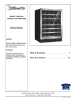
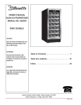
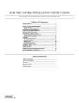
Pre-lnstallation
Kenmore
Electrical
Requirements
Requirements
Grounding
2
.....................................
2
.................................
2
Requirements
Water Supply Requirements
..............................
2
Drain Requirements
..........................................
2
Rough-In
..........................................
3
Location
Tumble ActionWasher.
..........................
Dimensions
Of Your Washer
..................................
4
Unpacking
.........................................................
4
Installation
.........................................................
5
Replacement
Parts .............................................
5
Before beginning installation, carefully read these instructions. This will simplify the installation
and ensure the washer is installed correctly and safely. Leave these instructions near the
washer after installation for future reference.
NOTE: The electrical service to the Washer must conform with local codes and ordinances
and the latest edition of the National Electrical Code, ANSI/NFPA 70.
Save These Instructions
Sears, Roebuck and Co., Hoffman Estates, IL 60179 U.S.A.
P/N 131801800
(9811)
_For
your safety the information in
this manual must be followed to minimize the risk of
fire or explosion or to prevent property damage,
personal injury or loss of life.
.
- Do not store or use gasoline or other flammable
vapors and liquid in the vicinity of this or any other
appliance.
- WHAT TO DO IF YOU SMELL GAS
• Do not try to light any appliance.
• Do not touch any electrical switch; do not use
any phone in your building.
• Clear the room, building or area of all occupants.
• Immediately call your gas supplier from a
neighbor's phone. Followthe gas suppliers
instructions.
• If you cannot reach your gas supplier, call the fire
department.
WATER
REQUIREMENTS
Tools Required for Installation:
1. l/4in, nutdriver
2. 318 in. socket with ratchet.
|_
3, 3/8 in. open end wrench.
4. 7/16 in. socket with ratchet.
5. 9/16 in, open end wrench.
6. Channel-lock adjustable pliers.
7. Carpenter's level.
ELECTRICAL
SUPPLY
REQUIREMENTS
Hot and cold water faucets MUST be installed within
42 inches (107 cm) of your washer's water inlet. The
faucets MUST be 3/4 inch (1.9 cm) garden hose type
so inlet hoses can be connected. Water pressure MUST
be between 10 and 120 pounds per square inch
(maximum unbalance pressure, hot vs. cold, 10 psi.)
Your water department can advise you of your water
pressure. The hot water temperature should be about
120 degrees F (49 degrees C).
Installation and service must be performed by a
qualified installer, service agency or the gas supplier.
PRE-INSTALLATION
Since your washer is equipped with a power supply
cord having an equipment-grounding conductor and
a grounding plug, the plug MUST be plugged into
an appropriate, copper wired receptacle that is
properly installed and grounded in accordance with
all local codes and ordinances or in the absence of
local codes, with the National Electrical Codes,
ANSI/NFPA 70 (latest edition). If in doubt, call a
licensed electrician. DONOT cut off or alter the
grounding prong on the power supply cord. In
situations where a two-slot receptacle is present, it
is the owner's responsibility to have a licensed
electrician replace it with a properly grounded
three prong grounding type receptacle.
DRAIN
1.
2.
3.
REQUIREMENTS
REQUIREMENTS
Drain capable of eliminating 17 gals (64.3 L) per
minute.
A standpipe diameter of 1-1/4 in. (3.18 cm)
minimum.
The standpipe height above the floor should be:
Minimum height: 24 in. (61 cm)
Maximum height: 96 in. (244 cm)
CIRCUIT - Individual, properly polarized and grounded
15 amp. branch circuit fused with 15 amp. time delay
fuse or circuit breaker•
96 in.
(244 cm)
Max.
POWER SUPPLY - 2 wire, with ground, 120 volt, single
phase, 60 Hz, Alternating Current.
OUTLET RECEPTACLE - Propedy grounded 3-preng
receptacle to be located so the power supply cord is
accessible when the washer is in an installed position.
GROUNDING
II
REQUIREMENTS
_j
[]
Impropar connection of the equipment grounding
conductor can result in a risk of electrical shock. Check
with a licensed electrician if you are in doubt as to
whether the appliance is properly grounded.
.
_
_
BACK =___
NOTE:
Drain hose attached to the washer can reach a 58
in. (147 cm) high standpipe• For higher standpipe
use hose P/N 131461201, available from Sears
Parts and Service. If drain is less than 24 in. (61
cm), install a siphon break kit, DIV 26110285320,
available from Sears Parts and Service.
The washer MUST be grounded. In the event of
malfunction or breakdown, grounding will reduce
the risk of electrical shock by a path of least
resistance for electrical current.
2
ROUGH-IN
<___ 17_
(43.2)
2 _.
24 ¾
(62.9)
r
DIMENSIONS
26_
(67.9)
<_60
__.
(152.4)
1
-(2.54)
(7.3)
(5.1) [_
o
)-
36
(91.5)
l'Li
Water
Inlets
Under
Counter
Poj;r
31%
(80.3)
34%
(87.9)
BACK
SIDE
i
K
inch (cm)
Roller Wheels
Adjustable Legs
UNDER COUNTER INSTALLATION
If an under counter* installation is desired, the washer MUST have a top sheet kit installed, P/N 131445600.
Kit is available from Sears Parts Department.
*Custom sized countertop is required.
+_
17
(43.2)-_
60
___
(152.4)
24 ¾
"_--
26¾
(67.9)
<--
(2.54)
(62.9) _
(7.3)
O
(
1½
------I
43%
(110.7)
81)
Power
o
(
33co1_"
--
u
SIDE
• ,_,
inch(cm)
BACK
_
m
AdjustableLegs
_
_
RollerWheels
3
m
LOCATION
OF YOUR WASHER
DO NOT INSTALL YOUR WASHER:
1. In an area exposed to dripping water or outside
weather conditions. The ambient temperature
should never be below 60 degrees F (15.6 degrees
C) for proper washer operation.
2. In an area where it will come in contact with
curtains or drapes.
3. In an area (garage or garage-type building) where
gasoline of other flammables are kept or stored
(including automobiles).
4. On carpet. Floor MUST be solid with a maximum
slope of 1/2 in. per foot (1.27 cm per 30.5 cm). To
ensure vibration or movement does not occur,
reinforcement of the floor may be necessary.
3.
4.
5.
6.
7.
8.
IMPORTANT
MINIMUM INSTALLATION CLEARANCES
When Installed in alcove or closet:
9.
Sides, Rear = 0 in. (0 cm)
Top = 0 in. (0 cm) Front Console Model
Top = 15 in. (36.1 cm) Rear Console Model
Remove the styrofoam base.
Carefully return the washer to an upright position
and remove the carton.
Carefully move the washer to within 4 feet (122cm)
of the final loCation.
Remove the following from the back side of the
washer: 4 bolts,
4 yellow plastic spacers,
4 metal "P" clamps.
Remove the service panel from the front of the
washer.
Remove the 4 nuts and 6 large washers that attach
the 2 yellow shipping braces to the drum and the
base. Lift up on the drum and remove the braces
(a yellow ribbon surrounds the items to be
removed). These braces must be removed to allow
the power supply cord to be released from the
shipping ring.
Remove the large styrofoam block located under
the drum. Lift up on the drum, tilt the base of the
foam block inwards toward the rear of the washer
until free, then pull it out.
10. Remove and discard the yellow ribbon and label
from the front of the washer.
When installed in closet: Front = 1 in. (2.54 cm)
Closet door ventilation required: 2 Iouvered openings
each 60 in2 (387 cm2), 3 in. (7.6 cm) from top and
bottom of door.
UNPACKING
1.
2.
Cut the shipping carton along the dotted line along
the base of the unit.
While in the carton carefully lay the washer on its
back side.
@
11. From the rear of the washer, carefully pull out the
power supply cord through the hole in the
backsheet.
12. Replace the service panel and screws.
NOTE:
4
If the washer is to be transported at a later
date, the shipping support hardware must
be reinstalled to prevent shipping damage.
Retain the hardware in the plastic bag
provided.
INSTALLATION
1.
.
,
.
.
Run some water from the hot
and cold faucets to flush the
water lines and remove
particles that might clog up
the water valve screens.
Connect the inlet hose ends
to the HOT and COLD water
faucets tightly by hand, then
tighten another 2/3 turn with
pliers. Turn the water on and
check for leaks.
NOTE: Use only new hoses provided with this unit.
Carefully move the washer to its final location.
Rollers on the rear of the washer allow for easy
movement in undercounter installations. Gently lift
up on the front of the washer and slide back.
NOTE: Lifting up more than 1/8" will engage the
rear legs. Do not use the dispenser drawer
or door to lift washer.
With the washer in its final position, place a level
on top of the washer (if an undercounter installation,
no rocking of the washer should exist). Adjust the
front leveling legs up or down to ensure the washer
is resting solid. Turn the lock nuts on each leg up
towards the base of the washer and snug with a
wrench.
NOTE: Keep the leg extension at a minimum to
prevent excessive vibration. The farther out
the legs are extended the more the washer
will vibrate.
The washer is designed to operate resting on its
rear rollers. If the floor is not level or is damaged,
the rear leveling legs may have to be extended. For
undercounter installations, rear leg adjustment is
accessible through the front service panel.
Form a U shape on the end of the drain hose with
the hose pointed toward the drain. Place in a
laundry tub or standpipe and secure with the cable
tie provided in the enclosure package.
NOTE: If the drain hose is placed in a standpipe
without forming a U shape, a siphoning
action could occur. There must be an air
gap around the drain hose. A snug hose fit
can also cause a siphoning action.
Cable
Tie
6.
Plug the power cord into a grounded outlet.
NOTE: Check to ensure the power is off at a
circuit breaker/fuse box before plugging
the power cord into an outlet.
7. Turn on the power at a circuit breaker/fuse box.
8. Read the Operating Instructions and Owner's Guide
provided with the washer. They contain valuable and
helpful information that will save you time and
money.
9. Run the washer through a complete cycle. Check
for water leaks and proper operation.
10. If your washer does not operate, please review the
"Avoid Service Checklist" in your Owner's Guide
before calling for service.
11. Place these instructions in a location near the
washer for future reference.
NOTE: A wiring diagram is located inside the washer
on the service panel.
REPLACEMENT
PARTS
If replacement parts are needed for your washer, call
Sears Parts and Service Toll Free Number
1-800-366-PART (1-800-366-7278).
Destroy the carton and plastic bags
after the washer is unpacked. Children might use them
for play. Cartons covered with rugs, bedspreads, or
plastic sheets can become airtight chambers causing
suffocation. Place all materials in a garbage container
or make materials inaccessible to children.
The instructions in this manual and all
other literature included with this washer are not meant
to cover every possible condition and situation that may
occur. Good safe practice and caution MUST be applied
when installing, operating and maintaining any
appliance.
Cable
Tie
I
Cable Tie
5
all the Safety and Operating instructions are
understood and practiced as a routine with your
Maximum benefits and enjoyment are achieved when
laundering tasks,