1
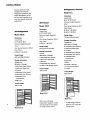
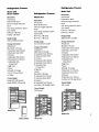
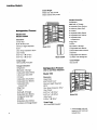
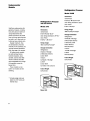
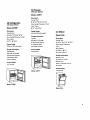
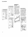
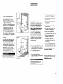
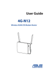
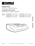
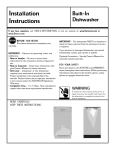
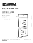
Ill
I
I
B
I
I I
I
I I IIIIll
U
I
L
I I I III I I IIiII
T
-
I
II
N
Planning
and
Installation
Guide
_SUiS-ZI=IEO_-
E
F
R
G
E
R
A
T
O
N
_Vhen
Will
Table of Contents
Only The Best
Do...Sub-Zero
Each Sub-Zero is protected
with a full two-year (parts and
labor) warranty on the entire
When only the best will do for
product from the date of
installation. The unmatched
Full-Size Models
4-7
you, look to the best. Look to
Sub-Zero protection also
Undercounter Models
8-9
Sub-Zero, the industry leader
includes a full five-year (parts
in built-in home refrigeration.
and labor) warranty and
Our 20 models vary in size
limited six-through-twellth-
from 18" to 48" in width, and
year (parts) warranty on the
offer storage space from 4.6
cubic feet to 30.
sealed system (compressors,
condenser, evaporator, drier
We offer the finest warranty
and all connecting tubing).
in the business in our 12-year
Sub-Zero Protection Plan. And
Warranty does not include
installation. See complete
if service is necessary, there
is a network of thousands of
warranty for non-residential
use and other exceptions.
Sub-Zero features and
fectory-trained technicians
across the United States and
Canada.
IMPORTANT
NOTE:
As you follow these instructions, you will notice warning
and caution symbols. This
blocked information is important for the safe and efficient
installation of this Sub-Zero.
There are two types of
potential hazards that may
occur during this installation.
options are listed on page 7.
This Planning and Installation
Guide is intended to offer you
a profile of our units, and
states a hazard may
what it takes to plan for and
cause serious injury or
install a Sub-Zero. If you
would like our colorful Full
death if precautions
are not followed.
Line sales brochure, or if you
have installation questions
that are not answered in this
Guide, please give us a call
signals a situation where
at (800) 222-7820.
We would also like to hear
minor injury or product
from you if you have any
comments on how we can
make this Guide a better tool
for you. Direct your comments
to the Marketing Services
Manager, Sub-Zero Freezer
damage may occur if you
do not follow instructions.
Another footnote we would
like to identify is:
IMPORTANT
NOTE:
Company, P.O. Box 44130,
This highlights information
that is especially relevant to
Madison, WI 53744-4130.
a problem-free installation.
Planning Information
10-11
Integrating Cabinetry
12-13
Installation Instructions
13-15
Panel Installation
16-19
Installation Check Ust
19
Full-Size
Models
Sub-Zero offers the most
Refrigerator/Freezer
complete line of built-in
Model 511
refrigeration options for your
design alternatives. Our 10
full-size models enable you to
Dimensions
Overall Size:
meet your specific needs and
H 84" W 30" D 24"
preferences.
Minimum Height Required:
All Freezer
82%"
Model 501F
Door Swing Clearance: 301/8 "
Door Panels:
Dimensions
All Refrigerator
H 481/16" x W 281/8"
Overall Size:
H 183/8"
Minimum Height Required:
Energy Usage
Dimensions
723/4 "
709 kwh/$61/Annually*
Overall Size:
Door Swing Clearance: 361/16"
H 73"W 36" D24"
Door Panel:
Minimum Height Required:
•H581s/16" x W 341/8 "
723/4"
Energy Usage
3 Adjustable Glass Shelves
Door Swing Clearance: 361/lS"
Door Panel:
876 kwh/$76/Annually*
1 Stationary Glass Shelf
H 5815/16" x W 341/8"
Storage Information
Storage Information
Refrigerator:
12.7 cu.ft, of Storage
2 Crispers
1 Adjustable Utility Basket
Freezer:
Energy Usage
19.2 cu.ft, of Storage
668 kwh/$58/Annually*
3 Adjustable Wire Shelves
Storage Information
1 Stationary Glass Shelf
Refrigerator:
X W
281/8"
H 73" W 36" D 24"
Model 501R
2 Adjustable Door Shelves
1 Adjustable Dairy
Compartment
2 Egg Trays
3 Drawers
20 cu.ft, of Storage
5 Adjustable Door Shelves
4 Adjustable Glass Shelves
Ice Maker with Storage Drawer
1 Stationary Glass Shelf
Crated Weight
4 Crispers
378 pounds
Freezer:
5.2 cu.ft, of Storage
Two Tier Pullout Drawer
Ice Maker
1 Adjustable Utility Basket
Crated Weight
3 Adjustable Door Shelves
430 pounds
1 Adjustable Dairy
Compartment
2 Egg Trays
Crated Weight
391 pounds
Model
501F
Model 511
Due to our continuous
improvement program, models
and specifications
Model
501R
are subject
to change without notice.
* Annual energy costs are
based on 8.67 cents per
kilowatt hour.
Refrigerator/Freezer
Refrigerator/Freezer
Model 550
Model 542
Model
Refrigerator/Freezer
550SS
Dimensions
Overall Size:
Model 561
Dimensions
H 84" W 42" D 24"
Overall Size:
Dimensions
H 84" W 36" D 24"
Minimum Height Required:
Overall
Minimum Height Required:
H 84"
Size:
W 36"
827/8"
D 24"
Door Swing Clearance:
827/8"
Door Swing Clearance: 361/16''
Minimum
Height
Required:
827/8 ''
Door Panels:
H 481/16" x W 341/8",
H 183/8" x W 341/8 "
Energy Usage
789 kwh/$68/Annually*
Storage Information
H 6711/16" X W 155/8"
Door Swing
Clearance:
203/4"
H 6711/16" x W 24"
Door Panels:
H 6711/16" x W 145/8':
Energy Usage
H 6711/16 '. x W 191/8"
858 kwh/$74/Annually*
Energy Usage
Storage Information
811 kwh/$70/Annually*
Refrigerator:
16 cu.ft, of Storage
Refrigerator:
15.7 cu.ft, of Storage
3 Adjustable Glass Shelves
1 Stationary Glass Shelf
2 Crispers
1 Adjustable Utility Basket
2 Adjustable Door Shelves
1 Adjustable Dairy
Storage Information
Refrigerator:
12.5 cu.ft, of Storage
4 Adjustable Glass Shelves
1 Stationary Glass Shelf
2 Crispers
1 Adjustable Utility Basket
3 Adjustable Door Shelves
Compartment
1 Adjustable Dairy
2 Egg Trays
Compartment
Freezer:
1 Egg Tray .
6.4 cu.ft, of Storage
Two Tier Pull-out Drawer
Freezer:
8.9 cu.ft, of Storage
Ice Maker
2 Adjustable Wire Shelves
Crated Weight
Model 550:482
1 Stationary Metal Shelf
pounds
Model 550SS: 515 pounds
4 Drawers
4 Adjustable Glass Shelves
1 Stationary Glass Shelf
2 Crispers
1 Adjustable Utility Basket
3 Adjustable Door Shelves
1 Adjustable Dairy
Compartment
2 Egg Trays
Freezer:
9.2 cu.ft, of Storage
3 Adjustable Wire Shelves
1 Stationary Metal Shelf
4 Drawers
5 Adjustable Door Shelves
Ice Maker with Storage Drawer
5 Adjustable Door Shelves
Crated Weight
Ice Maker with Storage Drawer
541 pounds
Crated Weight
500 pounds
\
Model 550
259/16"
Door Panels:
p
Model 550SS
Model
Model
561
542
Full-Size
Models
Crated Weight
Model 532:582
pounds
Model 532SS: 630 pounds
Storage information
Refrigerator:
18.2 cu.ft, of Storage
4 Adjustable Glass Shelves
1 Stationary Glass Shelf
Refrigerator/Freezer
4 Crispers
1 Adjustable Utility Basket
Model 532
Model 532SS
3 Adjustable Door Shelves
1 Adjustable Dairy
Dimensions
Compartment
Overall Size:
2 Egg Trays
H 84" W 48" D 24"
Freezer:
Minimum Height Required:
Model
11.2 cu.ft, of Storage
532
827/8"
3 Adjustable Wire Shelves
Door Swing Clearance: 291/4"
Door Panels:
2 Removable Plastic Shelves
3 Drawers
H 6711/16" X W 1716/16",
5 Adjustable Door Shelves
H 6711/16" X W 2711/16"
Model 532SS
Ice Maker with Storage Bin
Energy Usage
Crated Weight
929 kwh/$81/Annually*
610 pounds
Storage Information
Refrigerator:
Refrigerator/Freezer
18.8 cu.ft, of Storage
with Ice and Water Dispenser
4 Adjustable Glass Shelves
Model 590
1 Stationary Glass Shelf
4 Crispers
Dimensions
1 Adjustable Utility Basket
Overall
3 Adjustable Door Shelves
H 84"
1 Adjustable Dairy
Minimum
Compartment
4 Drawrers
Height
Door Swing
Required:
Clearance:
291/4"
Door Panels:
:1.l.2 cu.ft, of Storage
1 Stationary Metal Shelf
D 24"
827/8"
2 Egg Trays
Freezer:
2 Adjustable Wire Shelves
Size:
W 48"
H 6711/16" x W 151/8"
o_.
H 6711/16" X W 209/16 "
ModelS_
Grille Panel:
H 93/16" X W 463/16"
5 Adjustable Door Shelves
Ice Maker with Storage Drawer
Energy Usage
1111 kwh/$96/Annually*
* Annual energy costs are
based on 8.67 cents per
kilowatt hour.
Features
• Door Handles. All units
have our low-profile door
handles as a standard
feature. A D-style handle is
an option on Models 501R,
Features
and
Options
Sub-Zero's integrated design,
beauty and quality is evident
in all of these features-that
extended full-length handle is
freezer offers an automatic
• Door Swing. You can
ice maker providing crescent-
choose left or right door swing
shaped ice.
on our single door units as
well as our over-and-under
also offered as an option on
all models. Refer to Figure A,
Page IOA for panel sizing
information. With the Models
550SS and 532SS, the
ten 500 Series full-size units.
inch in diameter stainless
• Built-in Design. All
steel.
Sub-Zeros are only 24" deep.
• Grilles. Sub-Zero's 11"
They accept decorative door
Iouvered grille is standard
and side panels (50 lb. weight
limit per door panel), to match
on all models with the exception of the Model 590. An
virtually any cabinetry. The
optional easy-access (EA)
perimeter thickness cannot
panel grille that accepts
exceed 1/4':See pages 12 and
13 for details.
decorative panel inserts is
also available. In either
• Colored Panels. Optional
instance, you can order them
steel door and side panels
in one inch increments from
are available from our factory
10" to 15': Model 590 has
in three colors: almond,
stainless steel and white.
the EA panel grille standard.
The Models 550SS and
(Model 590 offers your
choice of seven complemen-
532SS have an attractive,
tary colored glasswells and
grille to complement the
ten optional color handle
overall professional look of
the units.
handle inset trim panel is
pin-striped pewter gray.) The
Models 550SS and 532SS
come with stainJess steel
panels.
moves easily on our roller
track system.
• Ice Maker. Each Sub-Zero
standard handles are one-
glasswell is pewter gray and
its own humidity control and
501F, 511 and 550. An
are standard on Sub-Zero's
inset trim panels at no cost.
The standard colored
• Crispers. Each crisper has
heavy-duty stainless steel
• Toe Plate. Adjustable,
solid toe plate meets the
standards of the American
Institute of Architects. Inset
area a 4" high by 3"deep. All
• Satin Trim. Door s_'_ws
units have a paintable black
toe plate except for the
Models 550SS and 532SS
are hidden on these units so
feature a stainless steel toe
you have a clean look.
plate.
• Adjustable
• Utility Basket. Smaller
items are stored in the
models. This option must be
utility basket.
ordered when requesting the
unit. You cannot reversethe
• Dairy i Egg Modules.
door in the field.
Two dairy compartments
• Magnetic Door Gasket.
have full magnetic seals to
Our positive sealing gasket
maintain freshness. A port-
ensures a tight closing door.
• Roller Base, Patented
refrigerator's adjustable
able egg tray offers handy
storage and is removable.
• Diffused
Ughting.
roller base assembly allows
for easy installation.
Sub-Zero's overhead lighting
• Door Stop Kit. For
floods both the refrigerator
installations where the door
and freezer compartments
swing must be limited to 90
with even light.
degrees, an optional Door
• Dual Compressors.
Stop Kit is available. Normal
Two compressors in all our
door swing is 130 degrees
combination refrigerator/
with the exception of the 511
freezer units deliver precise,
and 550(SS). The normal
and independent temperature
in the section it controls.
• Automatic Defrost.
door swing on these models
is 120 degrees.
Sub-Z ero refrigerator and
freezer units have an automatic defrost system.
• Front Venting. All
Sub-Zero units are front
vented so you can plan for
a truly built-in refrigerator.
Shelves.
Cantilever glass shelves in
the refrigerator, wire shelves
in the freezer and all of the
door shelves are adjustable.
7
Undercounter
Models
Refrigerator/Freezer
Model 249R
Dimensions
Overall Size:
H 3313/16"W 237/8" D 24"
Refrigerator/Freezer
with Auto Defrost
Door Swing Clearance: 253/s"
Door Panel:
Model 245
H 30" x W 235/8 -
gerators, freezers, combination units and ice maker all
Dimensions
Energy Usage
Overall Size:
368 kwh/$32/Annually*
accept decorative door
H 34" W 237/8" D 24"
panels (maximum 20 pound
Door Swing Clearance: 2513/16"
limit) to fit any decor and can
be built in to fit flush with vir-
Door Panel:
Sub-Zero undercounter refri-
H 281/8" x W 231/2 "
tually any base cabinet style.
Storage Information
Refrigerator:
4.4 cu.ft, of Storage
2 Removable Shelves
Energy Usage
1 Stationary Shelf
are all backed by the best
warranty in the business, the
463 kwh/$40/Annually*
3 Door Shelves
12-year Sub-Zero Protection
Storage Information
Plan. See page 3 for details.
All undercounter models
Refrigerator:
3 cu.ft, of Storage
1 Shelf
are self-venting, feature
2 Stationary Shelves
Manual Defrost
foamed insulation, have
1 Door Shelf
durable, easy-to-clean ABS
interior surfaces and offer
Freezer:
Crated Weight
1.9 cu.ft, of Storage
1 Shelf
120 pounds
Equally important, they
interchangeable
door swings.
Manual Defrost
(Kit required, except for
1 Door Shelf
Model 245.)
These models can be
Ice Maker with Container
built-in or installed as free
Crated Weight
standing.
139 pounds
* Annual energy costs are
.7 cu.ft, of Storage
Model
based on 8.67 cents per
kilowatt hour.
Model 245
8
Freezer:
249R
All Freezer
with Auto Defrost
Model 249FF
Dimensions
Overall Size:
H 3313/1s" W 237/8" D 24"
All Refrigerator
with
Auto
Door Swing Clearance: 253/8"
Door Panel:
Defrost
Model 249RP
H 30" x W 235/8"
Dimensions
Energy Usage
Overall Size:
504 kwh/$44/Annually*
Model 506
H 3313/zs" W 237/8" D 24"
Door Swing Clearance:
Ice Maker
Storage Information
253/8"
Freezer:
Dimensions
4.6 cu.ft, of Storage
Overall Size:
2 Removable Shelves
H
Energy Usage
1 Stationary Shelf
Door Swing Clearance:
429 kwh/$37/Annually*
Ice Maker Optional
113/4,,
Storage information
Crated Weight
Refrigerator:
135 pounds
Door Panel:
H 30" x W 235/e "
3413/32 " W 177/8"
D 237/8"
Door Panels:
4.9 cu.ft, of Storage
2 Removable Shelves
H 133/18" x W 17",
H 1115/15"x W 17"
Storage Information
35 Ibs. of Ice
1 Stationary Shelf
3 Door Shelves
3/4" Clear Ice Cubes
Hopper Door
Crated Weight
Drain or optional pump is
117 pounds
necessary.
Crated Weight
Model
Model
249FF
110 pounds
249RP
Model 506
9
Planning
Information
MODEL
Area
Requirements
Finished
Rough Opening
Dimensions
Minimum Door
Clearance
Required at 90 °
Recommended
Electrical
Outlet Location
Water
Supply
Location
D
E
F
723/4"
3"
6"
-
723/4"
3"
6"
-
30z/8"
827/8"
751/2"
_
_
361/16"
827/8"
751/2"
_
_
203/4"
827/8
751/2"
-
_
259/16"
827/8"
751/2"
-
_
A
B
¢
501R
351/2"
723/4"
361/±s"
501F
351/2"
723/4"
361/18"
511
29z/2"
833/4"
_0(._)
35±/2"
833/4"
561
351/2"
833/4"
411/2"
833/4"
Before moving ahead with
Minimum Height
Required
(with levelers in)
"
any planning you should be
53=(S5)
471/2"
833/4"
291/4"
82V8"
751/2 "
-
-
aware of the basic requirements for the installation of
590
471/2"
833/4"
291/4"
827/8"
751/2"
-
_
245
24"
341/2"
341/4
1"
2"
12"
a built-in Sub-Zero. The
249R
24"
341/2"
253/8"
341/4
101/2"
81/2"
--
drawings in Figures 1 and 2
249RP
24"
341/2"
253/8"
341/4
101/2"
81/2"
--
illustrate the finished rough
249FF
24"
34!/2"
253/8"
341/4
101/2"
21/2"
18"
in dimensions, electrical
506
18"
341/2"
113/4"
341/4
21/2"
21/2"
11"
and plumbing locations and
minimum door clearance for
IMPORTANT
all units.
2513/16"
NOTE: When using frameless cabinets,you must add space to the finished rough
openingto allow for side mainframeoverlapto ensurecabinet and Sub-Zerodoorsopen properly.This
space will fluctuate dependingon the installationandoverallvisual appearanceyou are tryingto achieve.
IMPORTANT NOTE: When installing cabinetswith six inch bases, add two inches to the minimum
height detailed above, if you want to make the base of the Sub-Zeroeven with the cabinets.
i LocateElectrical
Locate Electrical
Outlet within Top
Shaded Area
I |
LocateElectrical
/ OhUa';te_'_rhi:
II
|
I B LocateWaterSupplyD I
Locate 501F Water Supply
within Bottom
Shaded Area
I I __
IT
within Bottom
I/
ShadedArea
I/
Models 245, 249R,
249RP, 249FF and 506
/
-Shut OffValve
/,
A
Models
501R
._\
and 501F
/.
IIIIll lllllll
A
J
P_
Models 511, 5S0(SS), 561, 542,
532(SS) and 590
Figure I
10
i
Figure 2
FigureA
2M
These actual size drawings
offer you the opport_.unity_
better understand unique
3 _'
situations you may face in
some of your installations.
The page can easily be
1_" Panel
Standard
1" Panel
Full-Length
Handle
3/4"Panel
½" Panel
I
Y_"Panel
\
removed and photocopied or
used for your own tracings.
Figure A shows the
clearance you would have for
raised panels using the
standard f.ull-length handle or
the optional extended fulllength handle illustrated in
the dash line.
Figure B below illustrates a
typical 501 pair installation
where a filler strip is being
Door
used and the doors open at
the standard 130 degrees.
J
Depending on the configuration and panels, this filler
strip will vary.
Filler
Strip
Allowfor Filler
Door Closed
Lap Behind Flange
Main Frame
Hinge
130 ° door
2" filler
opening
strip
(top
with a
view)
(Optional 90 = Door
Stop Available)
Optional D-Style
Handle on 501 Pair
¢
Door Open @ :130°
FigureB
11
Nominal Overall
Width of Sub-Zero
23_" to Rear
of Sub-Zero
Main Frame
OH
\
W'
Door Closed
W'
Hinge
1¥,"
2"
I
I
----.
I
I
I
I
°----4
2_"
I
2Vi'
I
2_"
I
3"
I
3_"
I
I
I
I
I
I
Door Open @ 90 °
I
3½"
I
90 ° door opening
(top view)
_°"-'e°_"
I II
)_.J
u I
_L_J
Figure C
?..
This overall view of a unit,
its door and the relationship
to a counter, a built-inwall
appliance or corner shows
how a filler strip may prevent
damage to raised panels.
12
Installation
Instructions
_rlUe Size
Panel Size
10 x 30
83/±e" x 283/16"
11 x 30
93/z6" x 283/16"
12 x 30
103/16" x 283/16"
• Panels must be 1/4" thick
13 x 30
113/±e" x 283/ts"
around the _perimeter and
muted to allow for 1/4" edge,
14 x 30
123/ze" x 283/±6"
15 x 30
133/16" x 283/16"
except for Model 245, which
requires 3/8".
Panels
_" Panel
thicker
than ¼"
11 x 36
93/16" x 343/16"
The Sub-Zero 11" Iouvered
12 x 36
103/16" x 343/16"
grille is standard on all units
13 x 36
113/16" x 343/16"
ation. Before bringing the unit
into a house, it should be
with the exception of the
14 x 36
123/18" x 343/16"
uncrated outside. Remove
Model 590. An easy-access
15 x 36
133/16" x 343/16"
the box and wood base and
(EA) panel grille is available
10 x 42
83/16"
as an option for all models
11 x 42
93/16" x 403/16"
discard wood block and
and easily accepts decorative
12 x 42
103/16" x 403/16"
hardware to be used for
13 x 42
113/16" x 403/16"
14 x 42
123/18 " x 403/16"
blocking your unit.
In addition retract front
15 x 42
133/18" x 403/16"
10 x 48
83/16" x 463/16"
11 x 48
93/16" x 463/16 "
12 x 48
103/16.'x 463/16"
13 x 48
113/16" x 463/16"
14 x 48
123/16" x 463/16 "
To reduce the possibility
15 x 48
133/16" x 463/16"
of the unit tipping forward,
Panels
this 11" EA panel grille as a
standard feature. The Models
550SS and 532SS come
standard with an 11" heavy
duty stainless steel grille. A
15" heavy duty grille is also
available for these two
models.
Figure6
As with the standard grille,
• Thicker raised panels may
the EA panel grille can be
ordered in one inch incre-
require special consideration
ments from 10" to 15".
with door swings and clearance. See center pages IOA
and lOB.
• You may consider using an
optional extended handle.
See Figure A, Page IOA.
• Panels must not exceed 50
pounds for each door panel
on the full-size units and 20
pounds on the undercounter
units.
The installatton of a Sub-Zero
83/16" x 343/16"
panels. The Model 590 has
Panels
Unit
10 x :36
Grille
¼" thick or less
Moving
The following sizes should
be used when ordering decorative inserts for the EA panel
X 403/t6"
Any other custom grille
must meet required airflow
requirements and you should
contact Sub-Zero before
installing one.
grille. There is a 15 pound
weight limit on these inserts.
Side
Panels
is an easy task if you have
done the necessary prepar-
discard this material. Do not
leveler legs to ensure easier
movement of the unit for
installation.
R_kVlVl-'l_|_ll_e
']
you must reposition the
front levelers to make
contact with the floor. You
will have to extend these
legs when the unit is
finally positioned.
You should remove the
grille for easier transpor-
If side panels are to be used
tation through doorways
and later access to the
refer to pages 17 and 18, the
power cord.
side panel installation section
of the guide, for specifics
regarding sizing.
13
Installation
Instructions
Models
561,
511,
542
550,
To block the unit, using the
wood block and hardware
and 532
Remove center grille
Blocking
screw
and cut the red nylon shipping strap.
NOTE:
removed
must be
Model
To help prevent the unit
590
before grille is tilted
or damage can occur.
Tilt the grille forward and
release
studs against the wall where
IMPORTANT
This-screw
the spring(s)
behind grille.
from
See Figure 7.
from _jpping forward and
To remove Model 590 grille
provide a stable installa-
assembly, the inner grille
tion, the unit must be
panels assembly must first
secured in place with a
be removed. Uft up (1), then
solid soffit or wood block.
then pull top section down
and out of the top key slot (3)
as in Figure 9. Next, remove
the five mounting screws that
hold the outer grille panel
assembly to the top compartment. See Figure 10.
Gri!le
/
along the top of the Sub-Zero
between the unit and the
1/4 inch. See Figure 12.
• Position the wood block
between the unit and the
over the unit and secure it
soffit of one inch or less, as
using the screws and "L"
illustrated in Figure 11, you
do not need to block the unit.
brackets provided. Make sure
screws extend a minimum of
If this is not the case, you
must block the unit.
T/8of an inch into each of the
two wall studs. The wood
block must extend a minimum
of three inches over the unit.
Figure 7
See Figure 12.
• Using the front and rear
levelers, the unit must be
501R
and 501F
raised until it contacts the
wood block. See Figure 15.
To remove the 501 grille,
remove two (black) screws
located in the lowest louver
in the grille. Tilt the bottom
of thegrille
clear the unit. The space
above the unit with clearance
Inner Grille
Models
• Locate the Proper height to
must not be greater than
If there is a solid soffit
3
Screw
the ref;igerator is to be
located.
bottom of the wood block
pull out at the bottom (2),
Shipping Strap
provided, follow these steps:
• Locate and mark two wall
out and away, it
To reduce the possibility
Figure 9
will release from the top of
of cabinet tipping forward,
front levelers must be in
the grille. There is no grille
contact with floor. See
spring on the 501 units.
Figure 15.
See Figure 8.
Figure11
Figure 10
Figure 8
14
Figure 12
Installing
Leveling
Shut off the power to the
wall outlet.
With the unit positioned
properly you should level the
unit by turning the front leveling legs counterclockwise to
raise or clockwise to lower.
Protect any finished floor-
The rear levelers (rollers) are
For a finished look to the
ing before moving the
unit in place. All full size
Sub-Zero models are
adjusted from the front of the
Sub-Zero install the toe plate
base by turning the s/16"hex
bolt clockwise to raise and
as illustrated in Figure 16.
equipped with rollers, so
counterclockwise
you can easily move the
unit into place.
Solenoid
cabinet. See Figure 15.
Valve
upright for a minimum of
24 hours before connecting power.
However, before completing
this step check to ensure
the drain pan is positioned
properly.
If for any reason, the
unit has been laid on its
back or side, you must
allow the unit to stand
to lower the
To reduce the possibility
I
of the cabinet tipping
forward, the front levelers
/
Electrical
Garden Hose
Connection
Fitting
¼" Compression
Nut
must be in contact with
the floor.
Figure 13
In all cases the toe plate
must be removable for
servicing so any floodng
or molding must allow for
this removal. Refer to the
label mounted on the
Tum on water supply, check
Plug the unit into 15 amp
grounded outlet and roll
kickplate support for
all fittings for leaks and make
certain the electrical harness
height clearance.
is attached to the solenoid
the unit into desired posi-
valve. IMPORTANT
tion. Now you have to
connect the ice maker
water line.
The ice maker will not imme-
NOTE:
diately fill with water when
supplied to the valve. Allow
24 hours for proper ice
Cut the red nylon shipping
Front
Leveler
production.
strap holding the garden hose
Figure 15
fitting, compression nut and
sleeve to the toe plate
bracket. Connect the 1/4.
compression nut and sleeve
Figure 16-
on the copper tu_oingto the
hose fitting before attaching
the fitting to the solenoid
valve. Purge the water line
before the final hookup to the
valve. See Figure 13 and for
Model 590 see Figure 14.
Figure 14
15
Panel Installation
Models
511,
501R,
550,
561,
501F,
542,
Model
and 532
first removing the trim mold-
Slide the appropriate panel
into the frame as illustrated
ing as shown in Figure 17.
in Figure 18.
Remove the door handle by
The molding easily comes off
With the panel in position,
590
Remove the trim molding
in an identical manner as
illustrated in Figure 17.
Once the molding is
removed you can easily
remove the door screws on
by using a piece of tape to
replace handle, screws and
All Sub-Zero full-size 500
pull it away from the handle.
trim molding. The molding is
both the refrigerator and
Series units easily
accommodate front, grille
This removal will expose the
replaced by bowing the piece
freezer doors by using a
handle screws.
gently in the middle and
inserting the top and bottom
standard Phillips screwdriver.
Remove the handle trim
edges into the handle
channel first and then release
the door(s) as shown in Figure
the middle.
19, Complementary colored
and side panels as tong as
With a standard Phillips
you follow the points listed
screwdriver, remove door
earlier in the Integrating
Cabinetry section of this
handle on freezer and refrigerator door. The Models 511
guide. (The Models 550SS
and 532SS come standard
and 550 freezer door handle
handle trim panels and glass-
is on the top of the door and
wells are available through
with stainless steel panels
and one inch diameter
removed in the same manner.
your product distributor.
Next, remove the ice and
panels by sliding them out of
stainless steel handles, so
water glasswell by removing
panel and handle installation
the mounting screw. Then
is not necessary.) Installation
slide the glasswell up and pull
is easy following these
out as shown in Figure 19.
steps.
Front
Panel
Installation
J
If a metal or other thin material is used, a filler must be
inserted behind your panel to
ensure a proper fit. All frames
are designed to accept up to
1/4" material. Thicker pieces
must be routed to the 1/4"
Figure18
perimeter dimension. There
is a 50 lb. weight limit for
each door panel.
Figure 17
Figure19
16
Side
%" thiek ekle iNnunmlflti;e,d
up to caMne, l trim (top viow)
Panels
Back of Sub-Zero Unit
If side panels are being
bottom trim fillers held on by
utilized, check with your
installer for installation
the mounting screws. See
suggestions or consider
Figure 20.
In similar fashion remove
these options.
the screws holding the vertical trim strip. See Figure 20.
alternatives, you must drill
Remove the top and
Install the door panels by
sliding them into the frame
on the door and reverse the
earlier steps to reassemble.
Trim
In any of these installation
three holes equal distance
apart in the vertical section
of the aluminum frame and
install #6 x 3/8" pan head
screws to hold the panels in
place. See Figure 22.
Anchor the back portion
of the side panel with
decorative screws or nails.
Refer to Figures 23-27.
We do not recommend the
use of adhesives.
Us" Thick
Batten
/
_/_" Side Panel -Material
The dimensions supplied
are for a typical wood side
Side of
Sub-Zero Unit --
panel. If 1/4" panel or less is
used and inserted into the
Frame
return channel on the extrusion then a 241/4 " size is
Pan Head
_
Screw
necessary. The sheet must
also be notched as shown in
Figure 21.
I
I
I
Door
I
I
Figure 23
1.o,
Sub-Zero Unit
Pan Head
¼" thick side panel fitted
up to cabinet trim (top view)
Screw
Back of Sub-Zero Unit
Frame
Side of
Sub-Zero Unit
Side Panel
_" Thick Battens/_-
--
V," Side Panel
Material
Figure 22
Vs" Thick
Back-Up
Trim
Frame
|
Screws
Pan Head
Screw
!
Figure 20
D
Figure 24
p 3Figure21
17
Panel
Installation
EA Grille
Model
Panel
-
590
Remove the inner grille panel
½" thick side panel fitted
up to cabinet trim (top view)
assembly (refer to Figure 9
on page 14) and remove the
Back of Sub-Zero
top two corner screws and
Unit
pull away the top frame. See
Side
of
Sub-Zero
1/4"thick side panel fitted
in to cabinet trim (top view)
Unit
--
Panel
--
Lay the remaining panel
V_" Side
assembly on a flat surface
and insert the panel insert
Material
Back of Sub-Zero Unit
into position in the grille
frame as shown in Figure 28.
_" Rout
tls" Thick Batten /
Reattach the top frame and
Frame
V4" Side Panel -Material
Pan Head
Screw
Side of
Sub-Zero Unit
Hinge Adjustment
Figure 28.
[
T
If the doors are out of adjustment, the top or bottom hinge
may be adjusted by removing
and discarding the two small
shipping screws. See Figure
29. The top door hinges can
install the inner grille panel
be adjusted left to right and in
assembly back onto the unit.
or out by loosening the three
allen head screws. The
See Figure 9 on page 14.
2_ ¸
bottom door hinge is equipped
1
with two adjustment allen
head screws. See Figure 30.
Frame
Pan Head
,_::rew
TOp
Figure 26
_
Screv*
Metal side panel fitted
up to cabinet trim (top view)
Figure 25
Figure 28
Figure29
Door
Figure 27
ooo, I Inl
"i°'e
II
Cabinet
Hinge-
Figure 30
18
I
lU I
"OJ _
II
"
Installation
Check List
[] Is unit leveled properly on
a solid floo_ (Page 15)
For adjustment, use a
1/8" allen wrench to loosen
[] Is blocking necessary?.
screws (Models 511 and
(Page 14)
550(SS) excluded). This
allows the door to move left
17Vl"
1
to right or in and out.
[] Is drain pan installed
The importance of the
installation of your Sub-Zero
Once the adjustments are
cannot be overemphasized.
made be sure to tighten the
The proper Installation
allen screws tightly.
IMPORTANT
NOTE:
your unit is the responsi-
Normal door swing is 130
\
degrees, except for Models
511 and 550(SS). Normal
door swing on these models
bility of the selling dealer
or installer. The following
check list should be completed by the installer
Figure 31
is 120 degrees. An optional
of
to
insure no part of the installation has been overlooked.
90 degree door stop is
available.
Any question or problems
Anchoring
selling dealer.
pertaining to the installation
should be directed to the
Product
properl_
[] Is toe plate installed?
(Page 15)
[] Is grille screw back in
position? (Page 14)
[] Are panels installed
correctly? (Pages 16-18)
[] Are doors adjusted?
(Pages 18 and 19)
[] Does the customer
understand the unit's
operation?
It is recommended after
going through the installation
[] Is the icemaker switch
procedure that you anchor
turned on? (Models 561,
the unit to the opening. See
I-I Is unit operating? If not, is
Figures 31 and 32. Your
unit plugged in? Is refrigerator/freezer control on?
Sub-Zero product distributor
has an anchoring kit (part
542, 532(SS) and 590).
Give the customer the
warranty packet.
[] Is packing material
#4-20-090-0) for your use.
removed? (Page 13)
[] Is water supply line
Do not drill through model
and serial number tag.
connected to compression
Product Information
fitting? (Page 15)
Service m
Figure 32
and
1-800-222-7820
r_
Disconnect power to unit
before checking wiring
connections.
19
IIIII
I
B
I
I
I
I
U
L
Think
T
I
N
Safety!
If you are storing or disposing
of your old refrigerator, please
do it safely.
Child entrapment accidents
can be tragic.
_®
Sub-Zero
Freezer
Company,
Inc,
Post Office Box 44130
Madison, Wisconsin 53744-4130
(800) 222-7820
500PIG
R
E
F
R
G
12/96
Printed in the U.S.A.
E
R
A
T
O
N