1
U
INTRODUCTION
E
INTRODUCTION
CONTROLS,
INDICATORS AND
CONNECTORS
CONTROLS,
INDICATORS AND
CONNECTORS
BASIC SYSTEM
CONNECTIONS AND
ADJUSTMENTS
BASIC SYSTEM
CONNECTIONS AND
ADJUSTMENTS
POWER SUPPLY
POWER SUPPLY
PREPARATIONS
PREPARATIONS
SETTING AND
ADJUSTMENTS
BEFORE SHOOTING
DV CAMCORDER
GY-DV550
SHOOTING
OPERATION
INSTRUCTIONS
DV CAMCORDER
DV CAMKORDER
CAMESCOPE DV
SETTING AND
ADJUSTMENTS
BEFORE SHOOTING
SHOOTING
OPERATION
PLAYBACK MODE
TIME CODE
OPERATION
S.S.F. (Super Scene
Finder) FUNCTION
GY-DV550
INSTRUCTIONS
BEDIENUNGSANLEITUNG
MANUEL D’INSTRUCTIONS
USING EXTERNAL
COMPONENTS
PLAYBACK MODE
TIME CODE
OPERATION
S.S.F. (Super Scene
Finder) FUNCTION
USING EXTERNAL
COMPONENTS
SETUP MENU
SETUP MENU
FEATURES OF THE
CAMERA SECTION
FEATURES OF THE
CAMERA SECTION
OTHERS
OTHERS
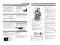
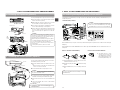
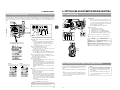
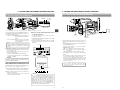
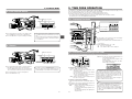
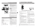
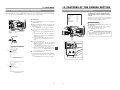
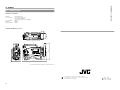
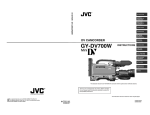
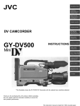
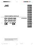
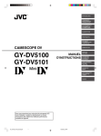
* The illustration shows the GY-DV550 DV Camcorder with the optional lens viewfinder attached.
* The illustration shows the GY-DV550 DV Camcorder with the optional lens viewfinder attached.
Thank you for purchasing this JVC product. Before operating
this unit, please read the instructions carefully to ensure the
best possible performance.
For Customer Use :
Enter below the Serial No. which is located on the body.
Retain this information for future reference.
This instruction manual is made from 100% recycled paper.
Model No. GY-DV550
Serial No.
SC96999 (U MODEL)
Thank you for purchasing this JVC product. Before operating
this unit, please read the instructions carefully to ensure the
best possible performance.
This instruction manual is made from 100% recycled paper.
SC961000 (E MODEL)
U
E
Thank you for purchasing the JVC GY-DV550 DV Camcorder.
IMPORTANT SAFEGUARDS
1.
2.
3.
4.
5.
6.
7.
8.
9.
10.
11.
12.
13.
14.
15.
16.
17.
18.
19.
Read all of these instructions.
Save these instructions for later use.
All warnings on the product and in the operating instructions should be adhered to.
Unplug this appliance system from the wall outlet before cleaning. Do not use liquid cleaners or aerosol cleaners.
Use a damp cloth for cleaning.
Do not use attachments not recommended by the appliance manufacturer as they may cause hazards.
Do not use this appliance near water – for example, near a bathtub, washbowl, kitchen sink, or laundry tub, in a wet
basement, or near a swimming pool, etc.
Do not place this appliance on an unstable cart, stand, or table. The appliance may fall, causing serious injury to a child or adult, and serious damage to the appliance.
Use only with a cart or stand recommended by the manufacturer, or sold with the appliance.
Wall or shelf mounting should follow the manufacturer’s instructions, and should use a mounting
kit approved by the manufacturer.
An appliance and cart combination should be moved with care. Quick stops, excessive force,
and uneven surfaces may cause the appliance and cart combination to overturn.
Slots and openings in the cabinet and the back or bottom are provided for ventilation, and to
insure reliable operation of the appliance and to protect it from overheating, these openings
must not be blocked or covered. The openings should never be blocked by placing the appliance on a bed, sofa, rug,
or other similar surface. This appliance should never be placed near or over a radiator or heat register. This appliance
should not be placed in a built-in installation such as a bookcase unless proper ventilation is provided.
This appliance should be operated only from the type of power source indicated on the marking label. If you are not
sure of the type of power supplied to your home, consult your dealer or local power company. For appliance designed
to operate from battery power, refer to the operating instructions.
This appliance system is equipped with a 3-wire grounding type plug (a plug having a third (grounding) pin). This plug
will only fit into a grounding-type power outlet. This is a safety feature. If you are unable to insert the plug into the
outlet, contact your electrician to replace your obsolete outlet. Do not defeat the safety purpose of the grounding
plug.
For added protection for this product during a lightning storm, or when it is left unattended and unused for long
periods of time, unplug it from the wall outlet and disconnect the antenna or cable system. This will prevent damage
to the product due to lightning and power-line surges.
Do not allow anything to rest on the power cord. Do not locate this appliance where the cord will be abused by
persons walking on it.
Follow all warnings and instructions marked on the appliance.
Do not overload wall outlets and extension cords as this can result in fire or electric shock.
Never push objects of any kind into this appliance through cabinet slots as they may touch dangerous voltage points
or short out parts that could result in a fire or electric shock. Never spill liquid of any kind on the appliance.
Do not attempt to service this appliance yourself as opening or removing covers may expose you to dangerous
voltage or other hazards. Refer all servicing to qualified service personnel.
Unplug this appliance from the wall outlet and refer servicing to qualified service personnel under the following
conditions:
a. When the power cord or plug is damaged or frayed.
b. If liquid has been spilled into the appliance.
c. If the appliance has been exposed to rain or water.
d. If the appliance does not operate normally by following the operating instructions. Adjust only those controls that
are covered by the operating instructions as improper adjustment of other controls may result in damage and will
often require extensive work by a qualified technician to restore the appliance to normal operation.
e. If the appliance has been dropped or the cabinet has been damaged.
f. When the appliance exhibits a distinct change in performance – this indicates a need for service.
When replacement parts are required, be sure the service technician has used replacement parts specified by the
manufacturer that have the same characteristics as the original part. Unauthorized substitutions may result in fire,
electric shock, or other hazards.
Upon completion of any service or repairs to this appliance, ask the service technician to perform routine safety
checks to determine that the appliance is in safe operating condition.
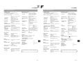
These instructions are for the GY-DV550E.
The instructions are given in three languages: English from page E-2 to E-104, German from page G-2 to G-104, French frompage F-2 to F-104.
This equipment is in conformity with the provisions and protection requirements of the corresponding European Directives. This
equipment is designed for professional video appliances and can be used in the following environments:
● residential area (in houses) or rural area
● commercial and light industry; e.g. offices or theatres
● urban outdoors
In order to keep the best performance and furthermore for electromagnetic compatibility we recommend to use cables not
exceeding the following length:
Port
Cable
DC IN
AUD IN FRONT
AUD IN REAR
LINE OUT
EARPHONE
DC OUT
GENLOCK/AUX IN
VIDEO OUT
Exclusive Cable
Shielded Twist Pair Cable
Shielded Twist Pair Cable
Exclusive Cable
Cable with earphone
Exclusive Cable
Coaxial Cable
Coaxial Cable
Length
5 meters
10 meters
10 meters
10 meters
2 meters
1 meter
10 meters
10 meters
Cable
Exclusive Cable
Coaxial Cable
Exclusive Cable
Exclusive Cable
Coaxial Cable
Coaxial Cable
Exclusive Cable
Coaxial Cable
Exclusive Cable
Length
5 meters
10 meters
10 meters
4.5 meters
10 meters
10 meters
2 meters
10 meters
200 meters MAX
Caution : Where there are strong electromagnetic waves or magnetism, for example near a radio or TV transmitter,
transformer, motor, etc., the picture and the sound may be disturbed. In such case, please keep the apparatus
away from the sources of the disturbance.
SAFETY PRECAUTIONS
WARNING:
TO REDUCE THE RISK OF FIRE OR
ELECTRIC SHOCK, DO NOT EXPOSE THIS
APPLIANCE TO RAIN OR MOISTURE.
This unit should be used with 12V DC only.
CAUTION:
To prevent electric shocks and fire hazards, do NOT
use any other power source.
WARNING ON LITHIUM BATTERY
The battery used in this device may present a fire or chemical
burn hazard if mistreated. Do not recharge, disassemble, heat
above 100°C (212°F) or incinerate.
Replace battery with Matsushita Electric CR2032, use of another
battery may present a risk of fire or explosion.
• Dispose of used battery promptly.
• Keep away from children.
• Do not disassemble and do not dispose of in fire.
For Sweden
NOTE:
The rating plate (serial number plate) is on the top frame.
CAUTION
To prevent electric shock, do not open the cabinet. No user serviceable parts inside. Refer servicing to qualified service personnel.
VARNING
Explosionsfara vid felaktigt batteribyte.
Använd samma batterityp eller en ekvivalent typ som
rekommenderas av apparattillverkaren.
Kassera använt batteri enligt fabrikantens instruktion.
For Norway
ADVARSEL
AVERTISSEMENT :
POUR EVITER LES RISQUES D’INCENDIE
OU D’ELECTROCUTION, NE PAS EXPOSER
L’APPAREIL A L’HUMIDITE OU A LA PLUIE.
Ce magnétoscope ne doit être utilisé que sur du
courant direct en 12V.
ATTENTION :
Afin d’eviter tout resque d’incendie ou d’électrocution,
ne pas utillser d’autres sources d’alimentation
électrique.
REMARQUE :
La plaque d’identification (numéro de série) se trouve sur le
panneau arrière de l’appareil.
2U
2
Port
REMOTE
MONITOR OUT
Y/C OUT
DV
TC IN
TC OUT
INTERCOM
PROMPTER OUT
VTR/RM
E-2
Lithiumbatteri–Eksplosjonsfare.
Ved utskifting benyttes kun batteri som anbefalt av
apparatfabrikantetn.
Brukt batteri returneres apparatieverandøren.
For Denmark
ADVARSELI
Lithiumbatteri–Eksplosionsfare ved fejlagtig handtering.
Udskiftning ma kun ske med batteri af samme˚ fabrikat og type.
˚ batteri tilbage til leverandøren.
Lever det brugte
For Finland
VAROITUS
Paristo voi räjähtää, jos se ön virheellisesti asennettu.
Vaihda paristo ainoastaan laltevalmistajan suoaittelemaan
tyyppiin. Hävitä käytetty paristo valmistajan ohjeiden mukaisesti.
SAFETY PRECAUTIONS
FOR USA AND CANADA
CAUTION
RISK OF ELECTRIC SHOCK
DO NOT OPEN
AUTION :
TO REDUCE THE RISK OF ELECTRIC SHOCK,
DO NOT REMOVE COVER (OR BACK).
NO USER SERVICEABLE PARTS INSIDE.
REFER SERVICING TO QUALIFIED SERVICE PERSONNEL.
U
WARNING:
TO REDUCE THE RISK OF FIRE OR ELECTRIC
SHOCK, DO NOT EXPOSE THIS APPLIANCE TO
RAIN OR MOISTURE.
Thank you for purchasing the DV Camcorder GY-DV550.
These instructions are for GY-DV550U.
This unit should be used with 12V DC only.
CAUTION:
To prevent electric shocks and fire hazards, do NOT use
any other power source.
This unit is a MiniDV video system format camcorder.
Videocassettes which are not marked with the MiniDV
symbol cannot be used with this unit.
NOTE:
The lightning flash with arrowhead symbol, within an
equilateral triangle is intended to alert the user to the
presence of uninsulated “dangerous voltage” within the
product's enclosure that may be of sufficient magnitude to constitute a risk of electric shock to persons.
The exclamation point within an equilateral triangle is
intended to alert the user to the presence of important
operating and maintenance (servicing) instructions in
the literature accompanying the appliance.
INFORMATION FOR USA
INFORMATION
This equipment has been tested and found to comply with the limits
for a Class B digital device, pursuant to Part 15 of the FCC Rules.
These limits are designed to provide reasonable protection against
harmful interference in a residential installation. This equipment
generates, uses, and can radiate radio frequency energy and, if not
installed and used in accordance with the instructions, may cause
harmfull interfrence to radio communications. However, there is no
guarantee that interference will not occur in a particular installation.
If this equipment does cause harmful interference to radio or
television reception, which can be determined by turning the
equipment off and on, the user is encouraged to try to correct the
interference by one or more of the following measures:
● Reorient or relocate the receiving antenna.
● Increase the separation between the equipment and receiver.
● Connect the equipment into an outlet on a circuit different from
that to which the receiver is connected.
● Consult the dealer or an experienced radio/TV technician for help.
CAUTION
CHANGES OR MODIFICATIONS NOT APPROVED BY JVC
COULD VOID USER’S AUTHORITY TO OPERATE THE
EQUIPMENT.
THIS DEVICE COMPLIES WITH PART 15 OF THE FCC RULES.
OPERATION IS SUBJECT TO THE FOLLOWING TWO
CONDITIONS : (1) THIS DEVICE MAY NOT CAUSE HARMFUL
INTERFERENCE, AND (2) THIS DEVICE MUST ACCEPT ANY
INTERFERENCE RECEIVED, INCLUDING INTERFERENCE
THAT MAY CAUSE UNDESIRED OPERATION
The rating plate (serial number plate) is on the top frame.
The following phenomena may occur when tapes recorded
on other units (including another GY-DV550) are recorded
or played back on this camcorder.
● The transient section between scenes recorded on other
units and those recorded on this unit may appear
disturbed.
● Digital noise may appear during playback due to tracking
errors.
CAUTION
To prevent electric shock, do not open the cabinet. No user serviceable parts inside. Refer servicing to qualified service personnel.
AVERTISSEMENT :
POUR EVITER LES RISQUES D’INCENDIE OU
D’ELECTROCUTION, NE PAS EXPOSER
L’APPAREIL A L’HUMIDITE OU A LA PLUIE.
Ce magnétoscope ne doit être utilisé que sur du courant
direct en 12V.
ATTENTION :
Afin d’eviter tout resque d’incendie ou d’électrocution,
ne pas utillser d’autres sources d’alimentation électrique.
REMARQUE :
La plaque d’identification (numéro de série) se trouve sur le panneau
arrière de l’appareil.
WARNING ON LITHIUM BATTERY
The battery used in this device may present a fire or chemical burn
hazard if mistreated. Do not recharge, disassemble, heat avobe 100°C
(212°F) or incinerate.
Replace battery with Matsushita Electric CR2032, use of another
battery may present a risk of fire or explosion.
• Dispose of used battery promptly.
• Keep away from children.
• Do not disassemble and do not dispose of in fire.
INFORMATION (FOR CANADA)
RENSEIGNEMENT (POUR CANADA)
This Class B digital apparatus complies with Canadian
ICES-003.
Cet appareil numérique de la Class B est conforme à la norme
NMB-003 du Canada.
3
3U
● This unit records and plays back in the SP mode.
Recording or playback in the LP mode is not possible.
● Due to manufacturing dispersion of tapes, we
recommend not to record pictures within the first 2 to 3
minutes from the beginning of the tape.
● Before recording important scenes, be sure to perform a
test recording and confirm that both video and audio are
recorded correctly.
● Recorded video and audio contents are for private use.
Other use may infringe on the rights of copyright holders.
● JVC cannot assume liabilities that may derive from the
impossibility of normal recording or playback of video or
audio due to malfunction of the camcorder or the
videocassette.
MAIN FEATURES
● Compact, lightweight design
Compact and light weight body was realized by use of magnesium die cast.
● DV high-quality digital format
The 4:1:1 (U MODEL)/4:2:0 (E MODEL), 8-bit, 25 Mbps component digital processing of the format ensures recording
and playback with high picture quality.
● High sound quality thanks to PCM audio
Two types of sampling, 16-bit, 48 kHz sampling and 12-bit,
32 kHz sampling, ensure high-quality digital audio.
● 26-pin camera terminal
The terminal can be used to connect an external VCR and
camera remote control unit. The recording VCR can be selected in the VTR SELECT switch.
(Main unit/parallel/external VCR)
● External video input capability
External composite video can be recorded with this unit.
● Character mixing capability for monitor output
Characters can be mixed for output to the MONITOR OUT
connector using menu setting.
● Audio reference recording level selected
The audio reference recording level can be set to -20dB or
-12dB in the menu.
● Normal/LETTER (16:9) screen switching capability
You can switch between 4:3 ratio screen and 16:9 ratio screen
in the menu.
● Concentrated LCD display (back-lit)
The concentrated LCD panel shows the time code and CTL
counter, tape remaining time, remaining battery power, audio levels, VCR section setup menus, hour meter data, and
a variety of warning indications. The display is back-lit to facilitate viewing in dark locations.
● Time code reader/generator
The built-in time code reader/generator can be used to record
SMPTE (U MODEL)/EBU (E MODEL) time code and user's
bits.
● Time code input/output connectors for slave lock capability
This unit can be slave-locked to an external time code generator which is connected to the time code input.
The data in the built-in time code generator is output from
the time code output terminal.
● Built-in monitor loudspeaker for audio checking
The input audio can be monitored in recording or EE mode.
The playback sound can be monitored in the playback mode.
The loudspeaker also outputs an alarm tone in case an abnormal condition occurs in the unit.
● Rec check function for convenient recording review
● Camera section designed with 3-CCD system for high-qual-
4
ity picture
Three 1/2" CCDs with 380,000 effective pixels employed.
Digital signal processing for reproduction of high-quality picture.
● Super sensitivity F/11, 2000 lux
Enables shooting at normal indoor illumination eliminating
the need for extra illumination.
● LOLUX for 0.75 lux (F1.4) illumination
Employment of LOLUX mode ensures +33 dB gain. This is
ideal for difficult shooting conditions with almost no illumination.
● Multi-Zone Auto Iris Detection Circuit
Multi-zone auto iris detection circuit ensures optimum iris position even in backlit conditions or when a bright subject moves in
a frame. Switch provided for selecting over or under level.
● Safety Zone indication in viewfinder
Two types of safety zone indicator functions provided.
Center mark can be turned ON/OFF.
● Zebra pattern video level indication in viewfinder
Select video level indicated by zebra pattern by means of
menu setting.
● Full Auto Shooting (FAS) function
Eliminating the need for troublesome switch or filter operations, the FAS function automatically provides a wide range
of compatibility with shooting conditions which varies as you
move between indoors and outdoors or between bright and
dark locations.
● Color temperature conversion filters for "3200K", "5600K +
1/8ND", "5600 K + 1/64ND" provided.
● Variable scan shutter
Eliminates flicker when shooting other screen pictures than
NTSC, such as computer monitor screens.
Copes with the range from 60.1 Hz to 2084.6 Hz.
● DV (i. LINK) connector
DV connector (4-pin) provided. Enables transfer of digital data
to other equipment provided with DV connector, such as a
non-linear editing controller.
● S.S.F. (Super Scene Finder) function
Enables memorization of the start point and ending point of
each scene or memorization of CUE points.
● Camera (Video) output, VCR playback output (composite/
YC) possible
● GENLOCK input connector
● Equipped with remote control system compatible GENLOCK
function with SC (Sub Carrier) lock.
● Built-in color bar (SMPTE type) (U MODEL)
Built-in colour bar (EBU type) (E MODEL)
● Superior operability with shutter speed and menus selected
by dial.
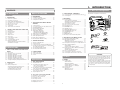
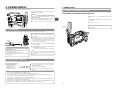
1.
1-1 Main Unit Configuration
CONTENTS
MAIN FEATURES ............................................................... 4
5. PREPARATIONS
1. INTRODUCTION
5-1
5-2
5-3
Main Unit Configuration ..............................................
Precautions for Proper Use ........................................
Routine and Periodical Maintenance .........................
Precautions for Use of Head Cleaning Tape ..............
Videocassette to be Used ..........................................
Battery Pack to be Used ............................................
Condensation .............................................................
Characteristic CCD Phenomena ................................
6
7
8
8
9
9
9
9
2. CONTROLS, INDICATORS AND CONNECTORS
2-1
2-2
2-3
2-4
2-5
2-6
2-7
2-8
2-9
2-10
Front Section ............................................................
Right Side Section ....................................................
Left Side Section ......................................................
Top Section ..............................................................
Adapter Section ........................................................
Rear Section ............................................................
Counter Display Contents ........................................
Lens (optional) .........................................................
1.5-Inch Viewfinder (optional) ...................................
Indications in Viewfinder ...........................................
• Warning LED Indicators Inside the Viewfinder .......
• Viewfinder Screen Display .....................................
10
12
18
19
20
22
24
25
26
27
27
27
PREPARATIONS
3. BASIC SYSTEM CONNECTIONS AND ADJUSTMENTS
3-1
3-2
3-3
3-4
3-5
3-6
3-7
3-8
Basic System ...........................................................
Attaching the Zoom Lens (optional) .........................
Attaching the Viewfinder ...........................................
Attaching the Microphone (provided) .......................
Attaching the Microphone (optional) ........................
Attaching the Tripod Base (provided) .......................
Attaching the 4-inch Viewfinder (VF-P400) ..............
Inserting and Replacing Backup Lithium Batteries ..
11. USING EXTERNAL COMPONENTS
BASIC OPERATIONS
INTRODUCTION
1-1
1-2
1-3
1-4
1-5
1-6
1-7
1-8
32
33
33
34
34
35
35
36
Turning the Power ON .............................................. 41
Cassette Loading and Unloading ............................. 42
Setting the Date and Time ........................................ 43
6. SETTING AND ADJUSTMENTS BEFORE
SHOOTING
6-1
6-2
6-3
6-4
6-5
6-6
Camera Settings ......................................................
Screen Size (4:3/16:9 aspect ratio) Mode Selection .....
Viewfinder Adjustment .............................................
External Monitor Adjustment ....................................
Back Focus Adjustment ............................................
White Balance Adjustment .......................................
• White Balance Adjustment .....................................
• Full-Time Auto White Balance (FAW) .....................
6-7 Mixing Characters to MONITOR OUT ......................
6-8 Switch Settings of the VCR Section .........................
6-9 Audio Input Signal Selection ....................................
6-10 Audio Input Level Adjustment ...................................
6-11 Monitoring Audio during Recording ..........................
44
44
45
45
46
47
47
47
48
49
50
51
52
7. SHOOTING OPERATION
7-1
7-2
7-3
7-4
7-5
7-6
Basic Recording Operation ...................................... 53
VCR Save Mode ....................................................... 55
If Unit is Left in Record-Pause (Standby) Mode ....... 55
Checking Recorded Contents in Record-Pause Mode
(Recording Check Function) .................................... 56
Recording External Video Signals ............................ 57
Recording with an External VCR .............................. 58
8. PLAYBACK MODE
8-1
8-2
8-3
4. POWER SUPPLY
AC Operation ...........................................................
Battery Pack Operation ............................................
• Attaching a Flat Shape Type Battery Pack .............
• Using an Anton-Bauer Battery Pack ......................
• Remaining Battery Power Display ..........................
• Precautions for the Battery Pack ...........................
37
37
38
39
40
40
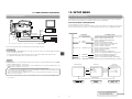
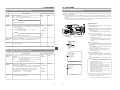
The GY-DV550 configuration is as shown below.
11-1 Connecting a Video Component with DV Connector 70
11-2 Connecting a PC ...................................................... 71
Playback Procedure ................................................. 60
Fast-Forward, Rewind .............................................. 61
Search ...................................................................... 61
12. SETUP MENU
12-1 VCR Setup Menu .....................................................
• VCR Setup Menu Configuration .............................
• Displaying and Setting VCR Setup Menus .............
• VCR Setup Menu Contents ....................................
12-2 Camera Menu Screen Flow .....................................
12-3 How to Select from the Camera Menu .....................
12-4 VF Display Screen ...................................................
12-5 OPERATION Screen ................................................
12-6 PROCESS Screen ...................................................
12-7 ADVANCED PROCESS Screen ...............................
12-8 SKIN COLOR ADJUST Screen ................................
12-9 FILE MANAGE Screen .............................................
12-10 SETUP Screen .........................................................
12-11 TIME DATE Screen ..................................................
12-12 Resetting of Camera Menu Setting Values ..............
72
72
73
74
76
77
78
79
80
81
81
82
83
84
85
13. FEATURES OF THE CAMERA SECTION
13-1 Full-Time Auto White Balance (FAW) .......................
13-2 IRIS (Brightness) Adjustment ...................................
• Adjustment of Lens Iris ..........................................
• Zebra Pattern Display during Manual Adjustment ......
13-3 Shooting the Screen Image on a Computer Monitor
13-4 Gain (Sensitivity) Adjustment ...................................
• Gain Switching .......................................................
• Gain Boost under LOLUX Condition ......................
13-5 Switch Setup According to Illumination and Subject
• Switch Functions ....................................................
• Full Auto Shooting (FAS) Function .........................
13-6 How to Use Skin Tone Detail ....................................
13-7 Connecting the Local Remote Control Unit ..............
13-8 Connecting the Camera Remote Control Unit ..........
APPLICATION
9-1
9-2
9-3
9-4
9-5
Displaying Time Code ..............................................
Presetting and Recording of Time Code ..................
• Time Code Presetting Procedure ...........................
• Presetting User's Bit Data ......................................
Recording Time Codes by Slave-Locking the Built-in
Time Code Generator with External TCG .....................
Recording Time Codes in Continuation of
Time Codes Recorded on Tape ...............................
Reproducing Time Codes .........................................
64
14-1 Troubleshooting ........................................................ 96
• Alarm Indications ................................................... 96
• Warnings in Viewfinder ........................................... 98
• Troubles with Error Code Outputs ........................ 100
• Troubles without Error Code Outputs ................... 101
14-2 Hour Meter Display ................................................ 102
14-3 Specifications ......................................................... 103
• Optional Accessories ........................................... 104
• External Dimensions ............................................ 104
65
65
10. S.S.F. (Super Scene Finder) FUNCTION
10-1
10-2
10-3
10-4
10-5
10-6
Explanation of the S.S.F. Function ...........................
How to Use the S.S.F. Function ................................
Deleting S.S.F. Data .................................................
Resetting S.S.F. Data ...............................................
Writing S.S.F. Data to Tape .......................................
Outputting S.S.F. Data ..............................................
66
67
68
68
69
69
5
LIGHT
ALARM
SHUTTER STATUS
MODE
ON
OFF
RM
VTR
MONITOR
SELECT
COUNTER
CH-1
MIX
CH-2
CTL
TC
UB
INCOM
MIC
CARBON
DYNAMIC
INCOM
MIC
MONITOR
CH-2
CH-1
CH-2
AUTO
MANUAL
FRONT
REAR
AUDIO SELECT
AUDIO INPUT
OFF
CH-1 AUDIO CH-2
CALL
LEVEL
AUTO IRIS
FULL AUTO
BLACK
BACK L
NORMAL
SPOT L
LEVEL
ON
CH-1
MENU
LOLUX
STRETCH
NORMAL
COMPRESS
RM
OFF
DC IN
/BATT.
POWER
VTR
GAIN
NG
OUTPUT WHT.BAL
OPERATE
ON
OFF
2
203
CR V
3
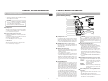
Lithium battery
Head cleaning tape
Tripod base
CAUTION :
14. OTHERS
62
62
63
63
OPERATE/WARNING
RESET
FILTER
1 3200k
2 5600k+1/8ND
3 5600k+1/64ND
Microphone
86
87
87
87
88
89
89
89
90
90
90
91
93
94
OTHERS
9. TIME CODE OPERATION
4-1
4-2
INTRODUCTION
6
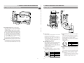
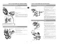
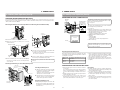
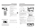
● The front base mount may be locked while the pin of the
tripod base is not inserted into the hole on the rear base
mount of the unit. Therefore, after mounting, make sure
that these parts are engaged properly.
● When moving the GY-DV550 mounted on a tripod, any
impact or vibration should be avoided as this may cause
the unit to become detached and to drop from the tripod.
Be sure to remove the unit from the tripod before
transporting it.
1. INTRODUCTION
1. INTRODUCTION
1-2 Precautions for Proper Use
● Supply voltage
Make sure that the power is between 11 V and 15 V DC. If
the power voltage is too low, abnormal color and increased
noise may occur. Do not exceed 15 V DC in any case, or the
unit could be damaged.
● Allowable ambient temperature and humidity
Be sure to use the unit within the allowable temperature range
of 0°C to 40°C and a relative humidity of 30% to 80%. Using
the unit at a temperature or humidity outside the allowable
ranges could result not only in malfunction but the impact on
the CCD elements could be serious as small white spots
may be generated. When storing the GY-DV550 for a long
time, the storage temperatures should be -20°C to 60°C.
● Strong electromagnetic waves or magnetism
Noise may appear in the picture or audio and/or the colors
may be incorrect if the camera is used near a radio or
television transmitting antenna, in places where strong
magnetic fields are generated by transformers, motors, etc.,
or near devices emitting radio waves, such as transceivers
or cellular phones.
● Use of wireless microphone near the camera
When a wireless microphone or wireless microphone tuner
is used near the camera during recording, the tuner could
pick up noise.
● Avoid using or placing the unit in places;
• subject to extreme heat or cold;
• with excessive dirt or dust;
• with high humidity or moisture;
• subject to smoke or vapour such as near a cooking stove;
• subject to strong vibrations or on an unstable surface.
• also do not leave the unit for long hours in a parked car
under direct sunlight or near room heating equipment.
● Protect the unit from being splashed with water (especially
when shooting in the rain).
● Protect the unit from being wet when shooting on a beach.
In addition, salt and sand may adhere to the camera body.
Be sure to clean the camera after use.
● Protect the unit against penetration of dust when using it in a
place subject to sandy dust.
● Optical performance of lens
Due to the optical performance of the lens, color divergence
phenomena (magnification chromatic aberration) may occur
at the periphery of the image. This is not a camera
malfunction.
1-3 Routine and Periodical Maintenance
● Noise may appear in the viewfinder when switching between
the playback picture and the EE picture.
● Setup level
The video signal of the unit's video output is provided with a
setup level when shipped from the factory. To turn off setup,
set SETUP in the Camera Setup screen to OFF.
● Use the unit in an upright position.
If placed on its side, heat release efficiency will deteriorate,
adversely affecting the tape transport. Depending on
circumstances the tape may also be damaged.
● Vibrations
Colors may fail to appear during VCR playback in locations
subjected to vibrations.
● Precautions for transportation
Do not drop or hit the unit against a hard object.
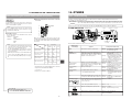
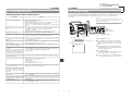
The GY-DV550 incorporates precision mechanical parts, which will collect dirt, wear out and deteriorate as the unit is used. On the
other hand, when the unit has been used for a long period in a normal environment, the heads, drums and tape transport mechanisms
also collect dirt deposited on them. Furthermore, dust which penetrates the inside of the VCR section especially during outdoor use
will promote the wear and deterioration of mechanical parts by causing poor contact between tape and heads or failing to maintain
the video and audio quality at high levels. To prevent wear and deterioration, clean the mechanical parts using a head cleaning tape
as routine maintenance. However, cleaning with a head cleaning tape alone is not enough for cleaning the entire tape transport
mechanism, it is also recommended to apply periodical maintenance (inspection) to prevent troubles that may be caused by the
sudden occurrence of failure. As the replacement, adjustment and servicing of parts require advanced skill and equipment, please
consult the person in charge of professional video equipment at your nearest JVC-authorized service agent.
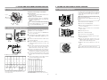
Head Cleaning
Periodical Maintenance
● To maintain beautiful pictures and sound, be sure to use a
head cleaning tape to clean the head periodically. (Read the
“Precautions for Use of Head Cleaning Tape” on page 8.) If
head cleaning is not performed periodically, a type of mosaic
noise called block noise may appear in the picture or sound
may be interrupted.
Contents : Check or replace the following mechanical parts
according to the running time.
Running Time
Drum ass’y (including heads)
Head cleaner
Tape guides & rollers
Rotary encoder
Belts & gears
Drive parts
● Remove the videocassette before transporting the unit.
● Do not insert an object other than a videocassette in the
cassette insertion slot. Be sure to close the cassette cover
when the unit is not to be used for a long period
● Do not set the OPERATE switch to OFF or remove the power
cable during recording or playback. Otherwise the tape may
be damaged.
● The sensitivity level of the provided microphone is set lower
than the reference input (- 60 dBs) setting.
● When the unit is not in use, be sure to set the POWER switch
to OFF in order to reduce power consumption.
● Cleaning the body: Wipe body with a dry, soft cloth. When it is
extremely dirty, soak the cloth in a solution of neutral
detergent, wring it out and then wipe. To prevent deformation
of the body, etc. and to avoid operation hazards, do not allow
volatile liquids such as benzine and thinner to touch the body,
and do not wipe it with a cloth soaked in such a liquid.
● The camera may be unstable in the period immediately after
the power is turned on, but this is not a malfunction.
Block Noise
40 30
CH 2
32k
AUD LOCK
20
10
OVER
0 dB
OVER
1500H
–
2000H
• The maintenance contents vary depending on the operating
environment and method. Therefore, the above data should
be considered as a reference.
Time management
The accumulated running time of the unit can be confirmed
with the hour meter display (which shows the accumulated drum
running time). For details, see "HOUR METER DISPLAY" on
page 102.
"RF" indicator
CH 1
1000 H
: Clean, check and adjust.
: Clean and check. Replace as required.
: Replace.
● Use the provided head cleaning tape. Do not use head cleaning
tapes other than specified. For instructions on how to use the
head cleaning tape and precautions for its use, read the
“Precautions for Use of Head Cleaning Tape” on page 8.
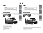
● When dirt adheres to the heads of the GY-DV550, the
following indications appear during playback and recording
check using the RET button on the lens section.
• “RF” appears on the display panel.
• “HEAD CLOG” appears on the counter display.
• “VTR WARNING (HEAD)” appears in the viewfinder.
● If this kind of indication appears, please stop the recording.
Head cleaning is required. This indicator disappears when
the OPERATE is turned OFF, or when the cleaning tape is
played back.
● If a tape containing recorded PAL signals is played back, the
GY-DV550 automatically enters the STOP mode. If this
happens, remove the videocassette so that the unit returns
to its normal state.
500H
–
For consultations related to the maintenance programming
or cost, please contact the person in charge of professional
video equipment at your nearest JVC-authorized service
agent.
RF
48k
SP
MENU
● When turning on the power with the tape inserted or after
loading a tape, the built-in head cleaner will emit a sound
while operating. However, this is not a malfunction of the unit.
"HEAD CLOG" indicator
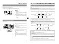
1-4 Precautions for Use of Head Cleaning Tape
Adhere to the following precautions when using the head cleaning tape.
1. The tape runs for 10 seconds at a time in the PLAY mode. (The tape stops automatically and then the unit enters the SAVE
MODE. However, the display back light is not turned off.) Press the PLAY button after the cleaning tape is fully loaded.
2. Do not use the tape more than four times at the most for each cleaning.
3. The cleaning tape can be used approximately 100 times.
CAUTION :
■ Use the following chart as a guide for periodical head cleaning.
● Do not point the lens or viewfinder directly at the sun or other strong light source.
• Eye damage could result.
• If the lens or viewfinder is left pointed at the sun, rays may collect inside the unit and cause damage or a fire.
● When carrying the camera, be sure to hold the carrying handle. Holding the lens or viewfinder may result in damage.
Operating
environment
Low temperature
0˚C to 10˚C
Room temperature
10˚C to 35˚C
High temperature
35˚C to 40˚C
Yardstick for use
of cleaning tape
1 to 2 times
every 5 hours
1 to 2 times
every 20 to 30 hours
1 to 2 times
every 5 hours
Note 1) When used in a low humidity environment (10% RH to 30% RH), head cleaning should be conducted at intervals half of those
given in the above chart.
Note 2) If an ME80 tape is used immediately after head cleaning, the VTR warning (head) indicator may remain on. In this case, let the
tape run as the indicator will turn off after the tape has run for a while.
Note 3) Use the cleaning tape in the room temperature (10˚C to 35˚C).
Note 4) The cleaning tape case contains instructions for use of the cleaning tape. However, some of these instructions differ from the
contents of this sheet. When using the cleaning tape, please follow the instructions of this sheet.
7
8
For servicing
See the service manual of the GY-DV500 (No. 60125) page 2-5,
“2.4 MAINTENANCE AND INSPECTION OF MAJOR PARTS”.
←
1. INTRODUCTION
1-5 Videocassette to be Used
● Use JVC’s videocassette tapes marked with MiniDV for
this unit.
Please use DVM60 or DVM30 type videocassettes.
● Videocassettes cannot be used upside down.
● Avoid storing a videocassette with unevenly wound tape,
as this may damage the tape. Rewind it to the beginning
before placing a cassette into storage.
● Store videocassettes in a place with little humidity and good
ventilation where mould does not form.
● After a videocassette tape has been used repeatedly,
it becomes unable to maintain full performance due to
an increase in noise caused by dropouts, etc. Do not
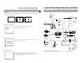
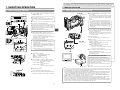
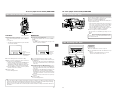
2. CONTROLS, INDICATORS AND CONNECTORS
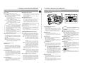
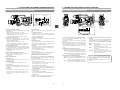
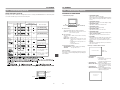
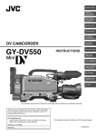
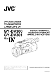
2-1 Front Section
continue to use a dirty or damaged tape, as this will
reduce the rotary head life.
● Videocassette tapes marked
MiniDV are provided with a
Switch
switch on the back for use in
preventing
accidental
REC
erasure.
● Slide the switch to SAVE to
SAVE
protect the required recording
in the tape from being
overwritten.
● To record on the tape, slide the
switch to REC.
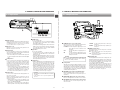
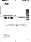
4 [LENS] Lens control connector
Connect 12-pin lens control cable from lens.
5 [ZEBRA] Switch
q
w
!1
VF
!0
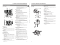
The GY-DV550 can use any of the following battery packs.
● Flat shape type
● Anton-Bauer battery pack: Trimpack 13/14 Series
Magnum 13/14 Series
Compack 13/14 Series
Propack 13/14 Series
* An Anton-Bauer battery pack cannot be connected directly
to the camera. It is necessary to mount the optional battery
holder.
● Battery holder: Anton-Bauer QRQ27
For details on how to mount the battery holder, see page
39.
e
To display the remaining battery power accurately, set the
VCR Setup Menu item No. 396 BATTERY TYPE according
to the type of the battery pack in use. (See page 75)
PUSH
1-6 Battery Pack to be Used
OFF
ON
r
t
ZEBRA
SKIN
AREA
AUTO
WHITE
ACCU
FOCUS
VTR AUDIO
LEVEL CH-1
10
o
i
TAKE
u
y
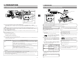
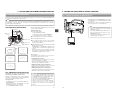
1-7 Condensation
● If the unit has been cooled down in a cold place and is then
carried to a warm place, the moisture contained in the warm
air may adhere to the head drum or tape guides and be cooled
into water droplets. This phenomenon is referred to as
condensation (dewing). When this occurs, the head drum
and tape guides are covered with droplets allowing the tape
to be stuck to them, leading to tape damage.
● Condensation occurs in the following cases:
• When the unit is suddenly moved from a cold place to a
warm place.
• When a room heater has just started or when the unit is
exposed directly to cold air from an air conditioner.
• When the unit is placed in a very humid place.
1 Viewfinder mount base, sliding securing ring
Do not leave the videocassette inserted when moving the camera
under conditions where the temperature environment changes.
● When condensation occurs in this unit, the DEW indicator on the
display lights up, and the WARNING LED blinks red. (See page 96)
To remedy, leave the unit with the power ON and wait until
the WARNING LED stops blinking red and the DEW indicator
disappears from the counter display.
DEW
OPERATE/WARNING
indicator
CH 1
40 30
CH 2
32k
AUD LOCK
48k
20
10
OVER
0 dB
OVER
PB
Mount the viewfinder on the base and secure it using the
sliding securing ring.
☞ See "Attaching the Viewfinder" on page 33.
2 [VF] Viewfinder connector (6-pin)
Connect the cable from the viewfinder here.
3 [AUDIO IN FRONT] Audio input front connector
(XLR 3-pin)
Audio input terminal for connecting camera microphone or
external audio devices.
• Set AUDIO IN FRONT LINE/MIC switch 6 on page 23
according to the connecting device.
• When recording audio from this terminal, set CH-1 AUDIO
INPUT switch 7 or CH-2 AUDIO INPUT switch 8 to
FRONT.
☞ See page 14.
AUTO OFF DEW
HOLD
SP
MENU
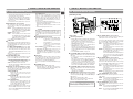
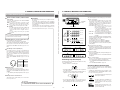
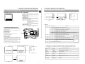
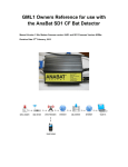
1-8 Characteristic CCD Phenomena
Smear and Blooming
Moire or Aliasing
Due to the physical structure of a CCD it is possible to induce
vertical streaking (called "smear") when shooting an extremely
bright light source. Another effect is the expansion of light around
a bright light or object (called "blooming").
The CCD employed in this unit is characterized by inducing
very little smear or blooming. Nevertheless, please be careful
when shooting a bright light source.
Smear
(Vertical pale streaking
appearing at high
luminous object)
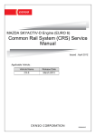
Shooting stripes or fine patterns may cause a jagged effect or
a banding in fine mesh patterns.
White dots
High luminous object
(Electric light, sunlight, etc.)
Monitor screen
3
2
High temperatures can cause CCD sensor pixels to malfunction
with the effect of white dots in the image. This condition is
conspicuous especially when gain is applied.
This is a characteristic of the charged-coupled device (CCD).
As far as possible, use the unit under conditions where the
temperature of the unit does not increase.
Function
1
GND
2
HOT
3
COLD
CAUTION:
The provided microphone is a phantom microphone. When
using the provided microphone, set AUDIO IN FRONT
LINE/MIC switch to MIC+48V ON.
When using audio input device other than a phantom
microphone, set AUDIO IN FRONT LINE/MIC switch to
LINE or MIC before connecting the device.
Blooming
(Blurring in highlight)
9
Pin No.
1
10
When this switch is ON, a zebra pattern is superimposed
on the viewfinder areas having video levels with a luminance
level of 70% to 80%. This pattern can be used as a reference
for manual adjustment of the lens iris.
When CHARACTER MIX of the Camera SETUP Menu
screen is set to ON, the zebra pattern will also appear in
the MONITOR OUT connector video.
Zebra patterns are also displayed during color bar display.
* The zebra patterns are not generated for the Y/C OUT
output.
☞ See "Zebra Pattern Display during Manual Adjustment"
on page 87.
• The default value is 70% – 80%. The luminance level can
be changed with the ZEBRA setting in the VF DISPLAY
Menu screen.
☞ See "ZEBRA" item on page 78.
While this switch is pressed to the SKIN AREA side, the
color tone areas specified with the SKIN DTL ADJUST item
on the ADVANCED PROCESS MENU are indicated in the
viewfinder. The switch returns to the OFF position when
released.
☞ See “How to Use Skin Tone Detail” on page 91.
• The Skin Tone Detail color tone areas are not indicated
while the VTR playback picture is shown in the viewfinder.
6 [VTR] VTR trigger button (record start/stop button)
Record start/stop can be effected with this button.
(It is interlocked with the VTR trigger button on the lens
section.)
7 [AUDIO LEVEL CH-1] CH-1 audio input level
control
Adjusts the audio input level of the CH1 audio signal.
Normally, the camera is used with the control set to the
maximum (10) position.
• To use this control, set the VCR Setup Menu item No.
246 CH1 FRONT VR ENABLE to "ENABLE".
Note:
Even when the VCR Setup Menu item No. 246 is set to
DISABLE, the recording level changes slightly when this
control is turned.
8 [AUTO WHITE/ACCU FOCUS] switch
AUTO WHITE:
• First, position a white object to occupy 80% of the centre
of the image.
• Setting this switch to the upper position ("AUTO WHITE")
will provide automatic adjustment for white balance.
* It is not activated in preset, full auto shooting, full-time
auto white balance and color bar modes.
☞ See "White Balance Adjustment" on page 47.
ACCU FOCUS:
• When this switch is set to "ACCU FOCUS" in the lower
position, the lens iris will be forced to open for
approximately ten seconds.
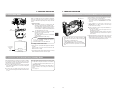
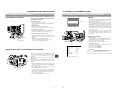
2. CONTROLS, INDICATORS AND CONNECTORS
2-1 Front Section (Cont’d)
2. CONTROLS, INDICATORS AND CONNECTORS
2-2 Right Side Section
[Camera Setting Section]
• The depth of field can be reduced and the lens focusing
can be adjusted more accurately.
q
w
e
r
t
y
u
CAUTION:
• As the automatic shutter is activated here, flicker may
appear on the screen depending on the lighting
conditions (such as a fluorescent lamp, etc.)
Colors may appear for white subjects.
• This operation is not possible in the LOLUX mode.
9 [TAKE] button
The Super Scene Finder (S.S.F.) function retains the time
code data for IN point and OUT point or CUE point in the
unit's memory.
☞ See “S.S.F. Function” on page 66.
0 Lens mounting ring/Lens lock lever
OPERATE/WARNING
RESET
MONITOR
SELECT
FILTER
ALARM
1 3200k
2 5600k+1/8ND
3 5600k+1/64ND
SHUTTER STATUS
CH-1
MIX
CH-2
MONITOR
MENU
CH-1 AUDIO CH-2
LEVEL
i
o
!0
AUTO IRIS
!1
!2
!3
VTR
FULL AUTO
BLACK
BACK L
NORMAL
SPOT L
LOLUX
STRETCH
NORMAL
COMPRESS
GAIN
NG
.BAL
OUTPUT WHT
OPERATE
ON
OFF
!4
Hold the lens and use the lever to turn the ring anticlockwise
to release lens.
To mount lens make sure the lens guide pin fits well, and
then turn the ring clockwise until firm.
☞ See "Attaching the Zoom Lens" on page 33.
1
[ALARM] Volume control
Turn to adjust the volume of the alarm tone that is output from
the monitoring loudspeaker or earphone in case of a warning
or other abnormal condition occurring with the GY-DV550.
Turn this control anticlockwise to reduce the volume. Setting
this control to the minimum position mutes the alarm tone.
! [FILTER] Color temperature conversion filter
control knob
This knob changes the internal color temperature filter.
☞ See "Camera Settings" on page 44.
2 [MONITOR] Audio monitor volume control
Adjusts the volume of the monitoring loudspeaker and
earphone. The audio is muted when this control is set to
the minimum position.
3 [STATUS] Status/menu button
• Pressing this button in the normal screen mode (condition
when menu is not shown) displays a status screen in the
viewfinder. The displayed status mode changes each time
the button is pressed.
☞ See "Status Screens" on page 27.
• Pressing this button for more than 1 second in the normal
screen mode displays the Camera Menu screen in the
viewfinder. Pressing this button while the menu screen is
displayed in the viewfinder makes the menu screen
disappear.
☞ See “How to Select from the Camera Menu” on page
77.
4 [SHUTTER/MENU] dial
• Pressing this dial once in the normal screen mode
(condition when menu is not shown) displays the shutter
speed for approximately 5 seconds. When this dial is
turned upwards while the shutter speed is displayed, the
shutter speed becomes slower. When turned downwards,
the shutter speed becomes faster. The selected shutter
speed is memorised for each file. To return the memorised
shutter speed to the factory preset, press the dial one
more time while the shutter speed is displayed.
• When this dial is turned upwards or downwards while the
menu screen is displayed, the cursor (>) also moves
upwards or downwards to allow selection of items in the
menu. To change the setting value of the item, press this
dial. When the setting value starts blinking, turn this dial
upwards or downwards to change the setting.
☞ See "How to Select from Camera Menu" on page 77.
11
12
CAUTION:
Due to the characteristics of the CCD, the screen will
appear to be slightly colored when changing the shutter
speed greatly. After changing the shutter speed, perform
white balance again.
White balance may not work properly for high-speed
shutters.
5 [LOLUX] LOLUX On/Off button
This button toggles the LOLUX mode on and off.
• LOLUX gain gives extremely low light level sensitivity for
special applications. This will result in an increase of 33
dB (approximately 45 times) in the LOLUX mode.
• LOLUX operation takes priority over normal gain setting.
• If the unit is placed in the LOLUX mode when it is in full
auto shooting mode, the auto level control (ALC) (one of
the full auto shooting functions) will be made inactive, so
that the LOLUX mode is given preference (FAW still
remains active).
☞ See "GAIN BOOST UNDER LOLUX CONDITION" on
page 89.
6 [BLACK] Black stretch/black compression switch
Switches the gain for the dark section of the image.
Set to an appropriate position depending on the video signal
to be shot.
STRETCH
: By stretching the signal only for the dark
section, contrast in the dark portion of
the image is enhanced.
NORMAL
: Standard mode.
COMPRESS
: When an entire image is relatively light
and the contrast is low, the gain of the
dark section is compressed to increase
the contrast.
7 [FULL AUTO] Full auto shooting ON/OFF button
and indicator
• This switch toggles the full auto shooting function on and
off.
• The indicator lights when in the full auto mode.
• Full auto shooting combines the auto iris, auto level control
(ALC) to automatically adjust the video signal level and
the white balance to their optimum levels.
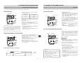
2. CONTROLS, INDICATORS AND CONNECTORS
2-2 Right Side Section [Cont’d]
• The iris is placed in automatic mode even if the iris
mode switch of the lens is in manual.
• The gain will vary continuously to the maximum of
+12 dB. The shutter speed will vary continuously to
the minimum of 1/240 (U MODEL)/1/200 (E MODEL) of a second.
☞ See "Full Auto Shooting (FAS) function" on page 90.
8 [AUTO IRIS] Auto iris level switch
This switch selects the automatic iris adjustment
reference value according to the condition in which the
camera is used.
BACK L : Under back light (Opens the iris more than
the standard level. The level of iris can be
set in SPOT L/BACK L of the OPERATION
MENU screen.) ☞ See page 79
NORMAL: Normal condition
SPOT L : Under spotlight (Closes the iris more than
the standard level. The level of iris can be
set in SPOT L/BACK L of the OPERATION
MENU screen.) ☞ See page 79
☞ See "SWITCH FUNCTIONS" on page 90.
9 [GAIN] switch
Electronically boosts the light sensitivity when there is
insufficient illumination on the subject. The boosting
level differs depending on the switch position as follows:
(Factory presets)
L : 0 dB (no boosting is applied)
M : 9 dB (boosted to approximately 3 times the original)
H : 18 dB (boosted to approximately 8 times the original)
• The boosting level for each switch position can be
changed with the OPERATION menu screen. (☞ See
page 79.)
The more the boosting level is increased, the more the
resulting image will be noisy.
0 [VTR SAVE/STBY] switch
Used to select the status of the GY-DV550 when the
power is turned ON and a videocassette is loaded.
STBY: The GY-DV550 is in the standby mode.
When a recordable videocassette is loaded, the
GY-DV550 enters the record-pause mode.
SAVE: The GY-DV550 is in the save mode.
• The status of the GY-DV550 is displayed on the Status
screen 1 in the viewfinder.
!
[OUTPUT] Color bar/Camera/Auto knee switch
This switch is used to select the output signal. When
the video signal from the shooting camera is selected,
the auto knee function is available.
CAM. AUTO KNEE ON:
Outputs the video signal from the shooting
camera. In this case mode, the auto knee
function is available.
CAM. AUTO KNEE OFF:
Outputs the video signal from the shooting
camera. In this mode, the auto knee function is
not available.
BARS. AUTO KNEE OFF:
Outputs the color bar signal. In this mode, the
auto knee function is not available. Set to this
position when adjusting the video monitor or
when recording the color bar signal.
• When the AUTO KNEE function is OFF, the point
where the KNEE function takes effect (knee point)
can be set using KNEE POINT in PROCESS MENU
screen. ☞ See page 80
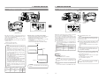
2. CONTROLS, INDICATORS AND CONNECTORS
2-2 Right Side Section (Cont'd)
AUTO KNEE function
When shooting a foreground subject, such as a human
being, etc., with a high-brightness background, if the
brightness level is set for the foreground subject, the
background image will be blurred with white. In such a case,
a clearer background is obtained when the auto knee
function is used.
It is effective especially in the following cases:
• When shooting a human being indoors with a view to the
landscape out through a window.
• When shooting a human being in the shade on a fine
day.
• When shooting a high-contrast scene.
[VCR Setting Section]
CH-1
AUDIO
LEVEL
5
6
7
CH-1
CH-2
CH-1
LIGHT
FRONT
REAR
AUDIO INPUT
FILTER
ALARM
1 3200k
2 5600k+1/8ND
3 5600k+1/64ND
SHUTTER STATUS
RM
VTR
CH-1
MIX
CH-2
CTL
TC
UB
CARBON
DYNAMIC
INCOM
MIC
MONITOR
CH-1 AUDIO CH-2
LEVEL
FULL AUTO
BLACK
LEVEL
ON
MENU
BACK L
NORMAL
SPOT L
INCOM
MIC
COUNTER
CH-1
AUTO IRIS
MODE
ON
OFF
CH-2
CH-1
AUTO
MANUAL
FRONT
REAR
AUDIO SELECT
AUDIO INPUT
VTR SELECT
SEE
INSTRUCTION
MANUAL
INT
PARA
EXT
LITHIUM BATT.
CH-2
OFF
CH-2
AUTO
MANUAL
AUDIO SELECT
OPERATE/WARNING
RESET
MONITOR
SELECT
8
CH-2
TC GENE.
PRST
REGEN
CAM AUX
CONTINUE
REC
FREE
GROUP
ITEM
HOLD
SHIFT
SELECT
G
MENU
DATA SET
ADVANCE PRESET
CALL
LOLUX
STRETCH
NORMAL
COMPRESS
RM
OFF
DC IN
/BATT.
VTR INPUT
POWER
CAUTION:
If a fast moving high-brightness section like a car in
sunlight is shot, the auto knee function may change
the brightness of the entire image along with the motion
of the object. In this case, set the auto knee function to
OFF.
@ [WHT.BAL] White balance switch
Three white balance modes are selectable with this switch.
B
: If white balance is performed with the
switch in this position, it will be
memorised into B.
A
: If white balance is performed with the
switch in this position, it will be
memorised into A.
PRST (PRESET) : A non-erasable white balance setting at
3200K.
• FAW (Full-time Auto White) mode can be set to A, B or
PRESET with the OPERATION MENU (see page 79).
In the FAW mode, video color temperatures are constantly
sampled for automatic adjustment to a proper white
balance.
VTR
OUTPUT WHT.BAL
H 0
OPERATE
ON
OFF
• Enables EE monitoring of the input audio signal during
recording, in the record-pause mode or in the stop mode.
Outputs the playback sound in the playback mode.
The sound to be output can be selected using the
MONITOR SELECT switch 4.
• The loudspeaker volume can be adjusted with the
MONITOR volume control 2 on page 12.
The audio from the loudspeaker is not output when an
earphone is plugged into the EARPHONE jack 2 on page
22. The warning alarm tones are also output through this
loudspeaker.
☞ See “ALARM INDICATIONS” on pages 96.
2 [CH1 AUDIO LEVEL] CH1 audio input level control
Adjust the audio input level of the CH1 audio channel with
this control.
• To use this control, set the CH1 AUDIO SELECT switch
5 to “MANUAL”.
This control works regardless of the setting of the VCR
Setup Menu item No. 246 CH1 FRONT VR ENABLE.
To use this control, set the AUDIO LEVEL CH-1 audio
input level control (7 on page 10) on the front section to
the maximum (10) position, or set the VCR Setup Menu
item No. 246 CH1 FRONT VR ENABLE to “DISABLE”.
Pressing this button while recording or in the record-pause
mode deletes the S.S.F. data stored in the memory of the
GY-DV550 with the S.S.F. (Super Scene Finder) function.
This function is only valid in the MARK mode.
☞ See “S.S.F. (Super Scene Finder) FUNCTION” on page
68.
$ [OPERATE] switch
3 [CH2 AUDIO LEVEL] CH2 audio input level control
Adjust the audio input level of the CH2 audio channel with
this control.
• This control is valid only when the CH2 AUDIO SELECT
switch 6 is set to "MANUAL".
4 [MONITOR SELECT] audio monitor selector switch
This switch is used to select the monitor sound output from
the monitoring loudspeaker 1 or via the EARPHONE jack
2 on page 22.
CH-1 : The CH1 channel audio is output.
MIX : CH1 and CH2 channel audio are output mixed.
CH-2 : The CH2 channel audio is output.
CAUTION:
Make sure to move switches all the way. Do not leave a
switch stopped in a midway position. Noise will be
generated and operation irregularities will occur.
13
9
B C D E
F A
1 23
[Audio setting]
1 Monitoring loudspeaker
# [NG] button
Turn the power ON and OFF with this switch.
• When this switch set to ON while a videocassette is
loaded, the GY-DV550 status differs depending on the
setting of the VTR (SAVE/STBY) switch 0.
GAIN
NG
14
5 [CH-1 AUDIO SELECT] selector switch
This switch is used to select the method for adjusting the
audio input level of the CH-1 audio channel.
The reference audio input level to the tape can be set using
No. 257 AUDIO REF. SIGNAL LEVEL in the VCR Setup
Menu screen (-20dB or -12dB). ☞ See page 74
AUTO
: The audio input level is held at the reference level
even when sounds greater than the reference
level are input.
The audio input level does not increase when
the input level is low.
MANUAL : The audio input level can be adjusted with the
CH-1 AUDIO LEVEL control 2 or the CH-1
AUDIO LEVEL control 7 on page 10.
To use the AUDIO LEVEL CH-1 audio input level
control on the front section, set the VCR Setup
Menu item No. 246 CH1 FRONT VR ENABLE to
“ENABLE”.
6 [CH-2 AUDIO SELECT] selector switch
This switch is used to select the method for adjusting the
audio input level of the CH-2 audio channel.
The reference audio input level to the tape can be set using
No. 257 AUDIO REF. SIGNAL LEVEL in the VCR Setup
Menu screen (-20dB or -12dB). ☞ See page 74
AUTO
: The audio input level is held at the reference level
even when sounds greater than the reference
level are input.
The audio input level does not increase when
the input level is low.
MANUAL : The audio input level can be adjusted with the
CH-2 AUDIO LEVEL control 3.
7 [CH-1 AUDIO INPUT] selector switch
This switch is used to select the input section of the CH1
audio channel.
FRONT : The sound from the AUDIO IN FRONT connector
on the front side section is input.
REAR : The sound from the AUDIO IN REAR connector
on the rear side section is input.
8 [CH-2 AUDIO INPUT] selector switch
This switch is used to select the input section of the CH2
audio channel.
FRONT : The sound from the AUDIO IN FRONT connector
on the front side section is input.
REAR : The sound from the AUDIO IN REAR connector
on the rear side section is input.
2. CONTROLS, INDICATORS AND CONNECTORS
2-2 Right Side Section (Cont'd)
[Video setting]
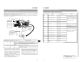
9 [VTR INPUT] VTR input setting switch
Select whether to record camera images or composite video
from an external device connected to the GENLOCK/AUX
IN connector 8 on page 18 with this unit.
CAM: Camera images are recorded
Synchronous signals can be inputted to the
GENLOCK/AUX IN connector.
Set the VCR Setup Menu item No. 126 INPUT
SELECT to CAMERA. ☞ See page 74
AUX: Composite video signals from the GENLOCK/AUX
IN connector are recorded. External video signals
are also outputted to the viewfinder.
Set the VCR Setup Menu item No. 126 INPUT
SELECT to CAMERA. ☞ See page 74
Memo:
• Camera images are outputted to the VIDEO OUT
connector 7 on page 18 and VTR/RM multi-pin
connector 8 on page 21, even with the AUX setting.
• When setting the VTR/RM switch on page 20 to RM,
the GENLOCK/AUX IN connector will be used for
synchronous signal input.
• When AUX is set, GENLOCK is not available for
MONITOR OUT and Y/C OUT signals.
• To input the image of the DV connector 1 on page
22, set the VCR Setup Menu item No. 126 INPUT
SELECT to IEEE 1394. ☞ See page 74
0 [VTR SELECT] VTR setting switch
Select whether to use this unit or an external VCR connected
to the VTR/RM multi-pin connector of page 21 for recording.
This switch is enabled only when [VTR INPUT] switch 9 is
set to CAM.
INT: This unit is used to record.
PARA: This unit and external VCR are used to record.
EXIT: Only the external VCR is used to record. Recording
on the external VCR can be started and stopped by
using the VCR start button on this unit.
[VCR menu/Time date setting]
! [MENU] button
Press this button to enter the VCR setup menu mode.
When the VCR setup menu mode is engaged, the "MENU"
indicator in the LCD display lights and the counter display
and viewfinder display are changed to the menu indication.
In the VCR setup menu mode, pressing this button resumes
the normal mode.
@ [HOLD/GROUP] button
• Press this button when presetting the time code or user's
bit. The presently displayed data is held (the "HOLD"
indicator lights on the display) and the leftmost digit of
the counter blinks. Pressing this button during presetting
of time code or user's bit cancels the operation and recalls
the previous display contents.
• In setup menu mode, this button is used to select the
menu group.
# [SHIFT/ITEM] button
• During presetting of time code or user's bit, press this
button to select the digit to be set. Each press of the button
shifts the digit to be set (which blinks) to the right.
• In setup menu mode, this button is used to select the
menu item.
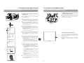
2. CONTROLS, INDICATORS AND CONNECTORS
2-2 Right Side Section (Cont'd)
[VCR Display Section]
$ [ADVANCE/SELECT] button
• During presetting of time code or user's bit, press to select
the value of the digit to be set. Each press of the button
increases the number by 1.
• In setup menu mode, this button is used to select the
value of a menu item.
u
wq
y
!7
t
CH 1
OPERATE/WARNING
LIGHT
RESET
% [PRESET/DATA SET] button
FILTER
ALARM
1 3200k
2 5600k+1/8ND
3 5600k+1/64ND
• During presetting of time code or user's bit, press to save
the set value in the preset memory. The set time code or
user's bit will be preset in the time code generator.
• In setup menu mode, this button is used to confirm the
menu item setting and save the data in the memory.
SHUTTER STATUS
CH-1
MIX
CH-2
CTL
TC
UB
CARBON
DYNAMIC
MONITOR
ON
CH-1
CH-1 AUDIO CH-2
LEVEL
FULL AUTO
BLACK
BACK L
NORMAL
SPOT L
LEVEL
CH-2
CH-1
CH-2
AUTO
MANUAL
FRONT
REAR
AUDIO SELECT
AUDIO INPUT
OFF
r
20
OVER
0 dB
OVER
10
CH 2
INCOM
MIC
INCOM
MIC
MENU
AUTO IRIS
RM
VTR
COUNTER
40 30
e
MODE
ON
OFF
MONITOR
SELECT
i
o
32k
AUD LOCK
MENU
48k
SLAVE
SP
WIDE
H
REMAIN
CALL
RM
OFF
AUTO OFF DEW
SERVO RF L i
NDF
M
REV FWD
LOLUX
STRETCH
NORMAL
COMPRESS
PB
H
DC IN
/BATT.
!6
HOLD
S
F
E BATT F
M
POWER
VTR
GAIN
NG
OUTPUT WHT.BAL
OPERATE
ON
OFF
!0 !1
!2
!3
!4
!5
• For details of the presetting of time code or user's
bit, see page 63.
• For details on the setup menus, see page 73.
^ [CONTINUE] button
If this button is pressed simultaneously with the LOG button
8 on page 19 during the stop mode, the tape winds to the
last S.S.F. data OUT point.
☞ See “About the Scene End Cue Up Function” on page
69.
TIME CODE GENERATOR setting switches
& [TC GENE] time code generator setting switch
Preset mode/regeneration mode setting switch for the time code
generator. In addition the switch is used to select the time code
run mode when in the preset mode. In the S.S.F. mode, time
code generator will change to the regeneration mode.
REC : Preset mode. Set to this position when newly
presetting and recording the time code. The time
code mode of the time code generator will be in
the REC run mode (time code runs only during
recording).
This position allows you to record continuous time
codes when recording scenes one after another.
FREE : Preset mode. Set to this position when newly
presetting and recording the time code. The time
code mode of the time code generator will be in
the FREE run mode (time code runs permanently).
Select this setting when the unit should be slavelocked with an external time code generator.
* If this position is used when recording scenes one after
another, the time codes become discontinuous at the
change points between scenes.
REGEN : Regeneration mode, in which the unit reads
existing time codes on the tape and records time
codes in continuation of the existing ones. Set to
this position when you want to add additional time
codes to time codes already recorded on the
tape.
* Lithium Battery Installation Compartment
Install a lithium battery (CR2032) in this compartment. The
battery is used for the backup of the time code and time
date. The GY-DV550 delivered without the battery installed.
The provided lithium battery is for test use. It is
recommended to install a new lithium battery. A new lithium
battery can power the backup for about one year. See "How
to Replace Backup Lithium Batteries" on page 36.
15
1 [OPERATE/WARNING] indicator
Normally lights green.
Lights orange during the VTR SAVE (tape protect) mode.
This indicator lights or blinks in red in the case of a warning
condition related to the remaining tape time, remaining
battery power or other abnormal condition in the unit.
For details, see "ALARM INDICATIONS" on pages 96.
2 [RESET] button
• Press to reset the CTL counter value.
* Pressing the button during presetting of time code or
user's bit resets the time code or user's bit data to
"00:00:00:00".
3 [LIGHT] switch
Turns the illumination of the back-lit display ON or OFF.
ON : The display is illuminated.
OFF : The display is not illuminated.
(Keep this switch at OFF during battery operation of the
GY-DV550 or when it is required to reduce the power
consumption for some reason.)
4 [COUNTER] switch
Selects the contents displayed on the LCD counter display.
The displayed contents when TC or UB is set can be
selected using the VCR Setup Menu item No. 516 DISPLAY
SELECT.
CTL : Set to this position to display the CTL counter.
TC : Set to this position to display time codes or for
presetting the time code. (When the Menu item No.
516 DISPLAY SELECT is set to “TC”)
Time (Hour, Min., Sec.) is displayed. (When the Menu
item No. 516 DISPLAY SELECT is set to “CLOCK”)
UB : Set to this position to display the user's bits of time
codes or presetting the user's bit. (When the Menu
item No. 516 DISPLAY SELECT is set to “TC”)
Date (Day, month, year) is displayed. (When the Menu
item No. 516 DISPLAY SELECT is set to “CLOCK”)
☞ See “VCR Setup Menu Contents” on page 75.
5 Audio level meters
Show the audio input level of the CH-1 and CH-2 channels
in the record mode or EE mode.
In the playback mode, the meters show the playback audio
level.
"OVER" lights in case of excessive input.
The reference recording level to the tape can be set using
No. 257 AUDIO REF. SIGNAL LEV in the VCR Setup Menu
screen (-20dB or -12dB). ☞ See page 74
16
CAUTION:
Immediately after the power is switched ON, the level
meters may fluctuate. This is not a malfunction.
6 SP indicator
Indicates the tape speed in record mode.
7 32k/48k sampling frequency indication
Indicates whether audio recording or playback occurs with
12-bit, 32 kHz sampling or 16-bit 48 kHz sampling.
• In the recording mode, the sampling frequency is set using
the VCR Setup Menu item No. 245 SAMPLING RATE.
In the playback mode, the indication conforms to the
sampling rate of the recorded sound.
8 [AUD LOCK] indicator
Indicates whether the audio signal is locked to the video
signal during recording and playback.
9 [MENU] indicator
Appears when the MENU button 1 on page 15 is pressed
to select the VCR Setup Menu.
0 WIDE indicator
• During IEEE1394 input, the unit will display the “WIDE”
indicator if the inputted data is of 16:9 aspect ratio.
• During playback and in the search modes, the “WIDE”
indicator is displayed if the recording was made in the
WIDE mode. The indicator remains off if the recording
was made in the NORMAL or LETTER mode.
! Cassette indicator
Lights when the unit is loaded with a
videocassette. Blinks during ejection or tape
loading.
@ [REMAIN] indicator
The remaining tape time (minutes and seconds) is shown.
For details, see page “Remaining Tape Time Display” on
page 24.
For servicing
The protocol of VCR control is not printed in this service manual. ←
2. CONTROLS, INDICATORS AND CONNECTORS
2-2 Right Side Section (Cont'd)
# Tape transport direction indicators
REV FWD
One of the indicators lights according to the
tape transport direction.
is displayed in the record-pause
mode and in the still picture mode.
$ Remaining Battery Power Display
The 7-dot segment bar display shows the remaining battery
power.
* To display the remaining battery power accurately, set
the VCR Setup Menu item No. 396 BATTERY TYPE
according to the type of the battery pack in use.
☞ See "Remaining Battery Power Display" on page 24.
% Counter display
• Usually, this section shows the data of the CTL counter,
time code or user's bit. The display mode can be selected
with the 4 COUNTER switch.
• Displays the VCR setup menu data when the GY-DV550
is in the VCR setup menu mode by pressing the MENU
button ! on page 15. The VCR setup menu includes the
hour meter (accumulated drum operating time).
• This section shows an error code when an abnormal
condition occurs with the unit.
☞ See "Counter Display Contents" on page 24.
☞ See "TROUBLES WITH ERROR CODE OUTPUTS"
on page 100.
^ Section for time code related indications
[SLAVE] Slave lock indicator
This is the slave lock indicator which lights when the builtin time code generator is slave-locked (synchronized) with
the LTC time code signal input at the TC IN connector.
For the slave lock of the time code, see page 64.
[PB] Time code playback indicator
Lights when the time code is in playback mode.
2. CONTROLS, INDICATORS AND CONNECTORS
2-3 Left Side Section
& Warning indicators
PUSH
[AUTO OFF] indicator
Lights when a non-recoverable error (e.g. tape winding
error, drum stopped, etc.) occurs with the unit. This
indicator also lights if condensation occurs.
☞ See "TROUBLES WITH ERROR CODE OUTPUTS"
on page 100.
w
o
e
LINE OUT
CH-1
REMOTE
AUDIO IN
FRONT
TC IN
TC OUT
r t y
1 Cassette cover
Pressing the EJECT switch on top of the section opens this
cover so that a videocassette can be inserted or removed
from the unit. The cover can be locked automatically by
pushing and closing it.
• If the cassette cover is not closed, the GY-DV550 will
remain inoperative.
Memo:
To prevent penetration of foreign objects into the unit,
do not leave the unit with the cassette cover open.
2 [MONITOR OUT] monitor output connector (BNC)
Connector for composite video signal output.
The following video signals are outputted.
• E-E video or playback video of VCR
• Screen mixed with characters.
• External video signal (When VTR INPUT switch is set to AUX)
Select whether to output the E-E video/playback video of
VCR or character-mixed screen by CHARACTER MIX of
the Camera Setup screen. ☞ See page 83
Memo:
• Select whether to output signals that include setup in
the E-E video in SETUP of the Camera Setup screen.
☞ See page 83
* Setup is not included during E-E of IEEE1394.
(U MODEL)
• VITC time code is not outputted from this connector.
Separate YC video signal output connector.
4 [TC IN] connector (BNC)
Input connector for the SMPTE-standard LTC signal. The built-in
time code generator can be slave-locked with the input time codes.
If the user’s bits should also be slave-locked, set the VCR Setup
Menu item No. 403 U-BIT SLAVE to “TC&UB”.
* When the TC GENE switch (& on page 15) is set to REC or
REGEN, or the VCR Setup Menu item No. 398 SSF MODE is set
to “CUE MODE” or “MARK MODE”, slave-locking will not take place.
For the slave lock of time code, see page 64.
5 TC OUT connector (BNC)
Output connector for the LTC signal from the built-in time
code generator.
The time code recorded on the tape is not output in play mode.
6 [LINE OUT CH-1/CH-2] connector (RCA)
Output connector for audio signals.
• Outputs the input audio signal in the record and stop
modes.
• Outputs the playback audio signal in the playback mode.
• Alarm sound is not output.
7 [VIDEO OUT] Video output connector (BNC)
Connector for composite video signal output.
Camera images are constantly outputted as through images.
Camera images are outputted even during external video signal input (when VTR INPUT switch 9 on page 15 is set to
AUX).
17
18
VIDEO OUT
CH-2
3 [Y/C OUT] connector (4P)
[HOLD] indicator
Lights when the time code generator display is held by
pressing the HOLD button in the time code setting block.
The time code or user's bit can be preset while this
indicator is lit.
☞ See “Displaying Time Code” on page 62.
i
PROMPTER
OUTPUT
GENLOCK/AUX IN
[Li] Lithium indicator
Lights and indicates the necessity of replacement when
the lithium battery that backs up data of the built-in time
code generator is nearly exhausted. ☞ See "Inserting and
Replacing Backup Lithium Batteries" on page 36.
[NDF] Non-drop frame indicator (U MODEL)
Lights when the internal time code generator or the
playback time code framing mode is non-drop frame. “DF”
is displayed in the drop-frame mode.
• It never lights when the CTL counter is displayed.
CAMCORDER
GY-DV550
Y/C OUT MONITOR OUT
[RF] indicator
Lights when the video head is clogged. Head clogging is
detected during playback and recording check using the
RET button on the lens section. Note that it is not detected
during recording.
* Should this indicator light up, clean the head using the
provided head cleaning tape. For instructions on head
cleaning tape, read “Precautions for Use of Head
Cleaning Tape” on page 8.
DV
VTR/RM
[DEW] indicator
Lights when condensation (dewing) occurs on the drum
or other mechanism in the unit.
The unit rejects all operations while this indicator is lit.
When the condensation has disappeared, the indicator
turns off and the unit accepts operations again.
[SERVO] indicator
Lights in the case of trouble with the drum servo during
recording to indicate that normal recording is not being
accomplished.
!0
q
u
LENS
• Whether to output signals with setup can be selected in
SETUP of the Camera Setup screen. ☞ See page 83
(U MODEL)
8 [GENLOCK/AUX IN] Generationlock/Aux signal input connector
Synchronous signals (black burst signals) are inputted when
the GY-DV550’s camera image is synchronized with an external component. Composite video signals are inputted
when recording video signals from an external device with
this unit. Which video signals to input can be selected using the VTR INPUT switch on page 15.
Memo:
• Video signals from this connector are not outputted to
the VTR/RM multi-pin connector 8 on page 21.
• When the camera remote control unit is connected
with setting the MODE switch 6 on page 20 to RM,
this connector will be used for synchronous signal input
regardless of the VTR INPUT switch setting.
• The camera cannot be synchronized with a VCR
playback signal.
• When the power is switched ON while an external sync
signal is input, the screen moves in a vertical direction
for a few seconds. this is not a malfunction.
• If the external sync signal is disrupted during recording,
the “SYnc inh” (SYNC INHIBIT) indicator is displayed
on the counter display and recording stops.
• If the external sync signal is disrupted during playback,
playback of the disturbed video image continues.
Start playback again after synchronization is obtained
and the signal is stabilized.
• The screen will distort when inputting sync signals to
both the main unit and camera remote control unit.
• This external video signal input (AUX IN) connector is
an auxiliary connector. The bandwidth of Y signals will
be 6.75 MHz (8 bit) regardless of the inputted signal
bandwidth.
9 [REMOTE] connector
A part of the unit's functions can be controlled externally.
For connecting the local remote control unit (RM-LP55/RMLP-57), nonlinear editing device, etc.
• When connecting the local remote control unit, Set VTR
Setup menu No. 050 REMOTE SELECT to LOCAL or
IEEE1394.
• When connecting a nonlinear editing device, set to
IEEE1394+RS232C.
For details, please consult your JVC dealer.
Note:
If you make an error in the setting, disconnect the
connector cable before performing setting again.
0 Microphone attachment holes
For attaching the microphone holder KA-A50 (optional).
☞ See "Attaching the Microphone (optional)" on page 34.
2. CONTROLS, INDICATORS AND CONNECTORS
2-4 Top Section
2. CONTROLS, INDICATORS AND CONNECTORS
2-5 Adapter Section
q
w
u
OPERATE/WARNING
PUSH OPEN
LIGHT
RESET
EJECT
FILTER
ALARM
1 3200k
2 5600k+1/8ND
3 5600k+1/64ND
SHUTTER STATUS
w
COUNTER
CH-1
MIX
CH-2
CTL
TC
UB
STOP
FF
PLAY
CARBON
DYNAMIC
CH-1 AUDIO CH-2
LEVEL
FULL AUTO
BLACK
BACK L
NORMAL
SPOT L
LEVEL
ON
STILL
AUTO IRIS
INCOM
MIC
INCOM
MIC
CH-1
REW
RM
VTR
MONITOR
MENU
LOG
MODE
ON
OFF
MONITOR
SELECT
CH-2
CH-1
CH-2
AUTO
MANUAL
FRONT
REAR
AUDIO SELECT
AUDIO INPUT
OFF
CALL
LOLUX
STRETCH
NORMAL
COMPRESS
RM
OFF
DC IN
/BATT.
y
t
e
r
w
q
POWER
VTR
i y r u e t
1 [EJECT] switch
Slide to the side when inserting or ejecting the videocassette.
Sliding this switch opens the cassette cover. If the switch is
moved while the power is off, the cassette cover opens but
it is not possible to insert or eject the cassette.
2 Operation cover
Open this cover when operating in the playback mode.
Otherwise, keep this cover closed.
3 [PLAY] button
Press to start playback. In play mode, the unit outputs the
video and audio signals of normal playback and the LED
indicator above the PLAY button lights.
* If the auto tracking is active at the moment the play mode
is entered, the playback video will be interfered with digital
noise.
4
[STOP] button
Press to enter stop mode. The drum keeps rotating in stop
mode. However, when stop mode has continued for about
30 minutes, the unit enters the tape protect mode, in which
the drum stops rotation and the tape tensioner is released.
It takes more time than usual to enter the record or play
mode from the tape protect mode.
* The time until the tape protect mode is initiated can be
set to 3 or 30 minutes with the VCR Setup Menu item No.
307 LONG PAUSE TIME. When used in a cold
environment, the setting will be 3 minutes regardless of
the setting on the VCR Setup Menu. ☞ See page 75.
5 [STILL] button
Press to enter the still picture mode during playback or in
the search or stop mode.
When the still picture mode has continued for about 30
minutes, the unit automatically switches to the stop mode.
(Tape protect mode)
* The time until the tape protect mode is initiated can be
set to 3 minutes or 30 minutes with the VCR Setup Menu
item No. 307 LONG PAUSE TIME.
When used in a cold environment, the setting will be 3
minutes regardless of the setting on the VCR Setup Menu.
GAIN
NG
L
OUTPUT WHT.BA
OPERATE
ON
OFF
6 [REW] button
Press to rewind the tape.
• Pressing the button in stop or fast forward mode initiates
the rewind mode. The LED indicator above the REW
button lights in this mode.
• Pressing the button during playback, still or forward search
initiates reverse search at about 10 times the normal play
speed. The LED indicators above the PLAY and REW
buttons light during reverse search.
1 [POWER] power source setting switch
The power source to this unit is selected using this switch.
When turning on the power, set this switch first.
DC IN/BATT : Use this setting when supplying power from
the DC INPUT connector of this unit or from
the battery.
OFF
: Use this setting when not supplying power to
this unit.
RM
: Use this setting when supplying power from
the camera control unit through the VTR/RM
multi-pin connector 8.
7 [FF] button
Press to fast forward tape.
• Pressing the button in stop or rewind mode initiates fast
forward mode. The LED indicator above the FF button
lights in this mode.
• Pressing the button during playback, still or reverse search
initiates forward search at about 10 times the normal play
speed. The LED indicators above the PLAY and FF
buttons light during forward search.
CAUTION:
When connecting an external VCR, set this switch to
DC IN/BATT and supply power from the DC INPUT
connector or the battery of this unit.
8 [LOG] button
• When the REW button is pressed while this button is kept
pressed, the S.S.F. data stored in the unit’s memory are
written to the tape. The LED indicator above the LOG
button lights while S.S.F. data is being written to the tape.
• When the CONTINUE button (F on page 15) is pressed
while this button is kept pressed in the stop mode, the tape
winds to the S.S.F. data’s last OUT point, after which the
unit enters the record-pause mode. (Scene End Cue Up)
The FF button’s LED blinks during Scene End Cue Up.
☞ See "Writing S.S.F. Data to Tape" on page 69.
CAUTION:
• Only the EJECT switch and STOP button work during
recording.
• If the cassette cover is open, all operations are
rejected.
2 [CALL] button
This button is pressed when sending call signals to a camera
control unit operator without using the intercom headset.
When this button is held down, BACK TALLY lamp 7 blinks
and call signals are sent to the camera control unit. When
releasing this button, the unit stops sending the call signals
and BACK TALLY lamp 7 turns off.
3 [INCOM MIC] intercom microphone ON/OFF switch
Microphone ON/OFF switch for the intercom headset.
Set the switch to OFF when not using the microphone of
the headset.
4 [INTERCOM LEVEL] intercom receiver volume
Knob for controlling the intercom headset receiver volume.
5 [INCOM MIC] intercom microphone setting switch
This switch is used to select the microphone type of the
intercom headset.
19
20
CARBON : Use this setting when using a carbon-type
microphone.
DYNAMIC : Use this setting when using a dynamic-type
microphone.
6 [MODE] setting switch
This switch is used to select the usage mode of the VTR/
RM multi-pin connector.
RM : This setting is used when connecting with the
camera control unit.
VTR : This setting is used when connecting and recording
using an external VCR
7 BACK Tally lamp
This lamp lights when the unit is in the recording mode. The
lamp flashes when the unit is shifting to the recording mode.
The lamp status and the lighting method can be selected in
No.082 BACK TALLY MODE of the VCR Setup menu.
☞ See page 74, “BACK TALLY MODE”
The lamp blinks when the camera control unit is connected
and while CALL button 2 is held down. The lamp turns off
when the CALL button is released. The lamp flashes when
a call signal is received from a camera control unit operator.
For details on the tally lamp display when connecting the
camera remote control unit, ☞ See page 95.
2. CONTROLS, INDICATORS AND CONNECTORS
2-5 Adapter Section (continued)
2. CONTROLS, INDICATORS AND CONNECTORS
2-6 Rear Section
!0
PUSH
PUSH
7
o
DV
VTR/RM
CAMCORDER
GY-DV550
DV
VTR/RM
CAMCORD
GY-DV550
8
PROMPTER
OUTPUT
9
GENLOCK/AUX IN
Y/C OUT MONITOR OUT
LINE OUT
CH-1
VIDEO OUT
CH-2
t
REMOTE
AUDIO IN
FRONT
TC IN
TC OUT
LENS
PROMPTER
OUTPUT
y
q
w
DV
LINE
MIC
+48V
ON
LINE
MIC
+48V
ON
FRONT
EARPHONE
Y/C OUT MONITOR OUT
LINE OUT
CH-1
CH-2
!1
INTERCOM
DC INPUT
TC IN
REMOT
TC OUT
AUDIO IN
REAR
DC
OUTPUT
e
8 [VTR/RM] VTR/RM multi-pin connector (26P)
r
u
i
BREAKER
This connector is used to connect an external VCR or
camera control unit. Camera image signals are outputted
from this connector.
Set MODE switch 6 according to the connecting device.
Memo:
• Camera images of this unit are recorded on the
external VCR. Compost video signals from GENLOCK/
AUX IN connector 8 on page 18 are not recorded.
• When recording on an external VCR, set the VTR
INPUT switch 9 on page 15 to CAM and set the VTR
SELECT switch = to PARA or EXT.
• Only CH1 audio can be outputted for audio signals.
Bottom side
4 [AUDIO IN REAR] audio input rear connector (XLR
1 [DV] connector
Using a DV cable (optional), a digital video component with
DV connector can be connected here.
This connector is used for output of the DV signal or to
input the VCR control signal from the digital video
component with DV connector.
• To remote control the VCR with a VCR control signal from
this connector, set the VCR Setup Menu item No. 050
REMOTE SELECT to "IEEE1394".
9 [PROMPTER OUTPUT] prompter output connector
Return video signals of the external VCR or signals inputted
to the AUX input connector of the camera remote control
unit are outputted through VTR/RM multi-pin connector 8.
3-pin)
Connect the external audio equipment or microphone to
this connector. Set the AUDIO IN REAR LINE/MIC select
switch 5 according to the connected equipment.
To record the audio of this connector, set the CH-1 AUDIO
INPUT switch 7 or the CH-2 AUDIO INPUT switch 8 on
page 14 to "REAR".
(AUDIO IN connector)
2 [EARPHONE] earphone jack
This is a mini-jack for connecting an audio monitoring
earphone. Plug in an earphone or headphone with a 3.5
mm diameter plug. Audio is outputted in monaural.
The earphone can also be used to monitor alarm tones
depending on situations.
The sound from the monitoring loudspeaker is interrupted
when an earphone is connected here.
Power output connector to a wireless microphone
transmitter, etc. The supply voltage is identical to the voltage
supplied to the unit (DC 12V max. 0.1 A).
1
No.
1
3
2
(Surface profile)
21
22
1
1
3
Signal
GND
2
HOT
3
COLD
5 [AUDIO IN REAR LINE/MIC] AUDIO IN REAR select
switch
3 [DC OUTPUT] connector
4
No.
2
Signal
GND
2
—
3
—
4
DC +12V (power through)
Selects the audio signal input to the 4 AUDIO IN REAR
connector.
LINE : Set to this position when connected to audio
equipment, etc. The reference input level is +4 dBs.
MIC : Set to this position when the microphone is
connected. The reference input level is -60 dBs.
MIC +48V ON:
Set to this position when the microphone requiring
+48 V power supply (phantom microphone, etc.) is
connected.
This connector supplies +48 V DC current.
2. CONTROLS, INDICATORS AND CONNECTORS
2-6 Rear Section (Cont'd)
6 [AUDIO IN FRONT LINE/MIC] AUDIO IN FRONT
select switch
Selects the audio signal input to the AUDIO IN FRONT
connector 3 on page 10.
LINE : Set to this position when connected to audio
equipment, etc. The reference input level is +4 dBs.
MIC : Set to this position when the microphone is
connected. The reference input level is -60 dBs.
MIC +48V ON:
Set to this position when a microphone requiring +48
V power supply (phantom microphone, etc.) is
connected. This connector supplies +48 V DC
current.
Use this setting when using the provided
microphone.
CAUTION:
When connecting a component that does not require +48
V power supply, make sure that the switch is not set to this
position before the connection is made.
2. CONTROLS, INDICATORS AND CONNECTORS
2-7 Counter Display Contents
The counter display shows the following 4 types of information.
! [BREAKER]
OPERATE/WARNING
The breaker trips when the power consumption exceeds
the capacity.
If the breaker trips, confirm that the power consumption
does not exceed the wattage rating. Then press BREAKER
before turning the power ON again to put the camera in the
operating status.
If the unit still does not work normally, please consult the
person in charge of professional video equipment at your
nearest JVC-authorized service agent.
CH 1
RESET
40 30
CH 2
32k
AUD LOCK
MONITOR
SELECT
SLAVE
AUTO OFF DEW
SERVO RF L i
PB
H
NDF
M
REMAIN
REV FWD
H
1. Tape counter display
HOLD
S
F
E BATT F
M
COUNTER
CTL
TC
UB
COUNTER
switch
Counter display
CTL
TC
UB
“CTL”
CTL
TC
UB
“TC”
CTL
TC
UB
“UB”
CTL
TC
UB
“TC”
VCR Setup
Menu No. 516
DISPLAY SELECT
H
M
S
F
H
M
S
F
“CLOCK”
CTL
TC
UB
CTL counter
Time code
User’s bit
Hour Min
Sec
Time display
H
Input terminal for the intercom headset.
Connect the JVC Intercom KA-310 to this terminal.
This terminal is enabled when the VTR/RM connector (26pin) on page 21 is connected to the camera control unit.
(Enabled when the MODE switch 6 on page 20 is set to
RM.)
LIGHT
ON
OFF
1. Tape counter display
“TC”
7 [INTERCOM] intercom input terminal (XLR 5-pin)
48k
OVER
0 dB
OVER
10
SP
WIDE
MENU
CH-1
MIX
CH-2
20
M
S
“UB”
Date display
Month Day
Day
Month
Year
Year
(U MODEL)
(E MODEL)
2. VCR Setup Menu setting display
2. VCR Setup Menu display
4.
Error code display
8 [DC INPUT] connector (XLR 4-pin)
Power input connector for 12 V DC. Connect with the AAP250 optional AC power adapter. When a cable is connected
here, the power supply from the battery pack is interrupted
and the source is switched to the power supplied through
this connector.
When supplying power to the unit from this connector or
battery, set the POWER switch 1 on page 20 to DC IN/
BATT..
1
4
2
9
3
This display is used when setting the setup menus. After
setting of the setup menus, the tape counter display returns.
For details, see "DISPLAYING AND SETTING VCR SETUP
MENUS" on page 73.
3. Hour meter display
3. Hour meter display
4.
Alarm display
H
The hour meter is displayed by selecting the HM group from
the VCR Setup Menu.
The hour meter data refers to the accumulated head drum
running time.
4. Error code/Alarm display
Signal
Remaining Tape Time Display
1
GND
2
—
This display shows the remaining tape time (minutes/seconds)
in record and play modes.
3
—
• Example: 30 minutes of remaining tape.
4
+12V
No.
The counter display usually functions as a tape counter
(hour, minute, second, frame). It can be switched to a CTL
counter, time code or user's bit display by using the
COUNTER switch. (When the VCR Setup Menu item No.
516 DISPLAY SELECT is set to “TC”.)
• CTL counter: Time between -9 hr. 59 min. 59 sec. 29
frames and 9 hr. 59 min. 59 sec. 29 (U)/24
(E) frames can be displayed.
* CTL counter indication may also corrupt
at playback of segment which time code
signal is not continuously recorded.
• Time code : Time between 0 hour and 23 hr. 59 min. 59
sec. 29 (U)/24 (E) frames can be displayed.
• User's bit : Hexadecimal number from 0 to F is displayed
in 8 digits.
When the VCR Setup Menu item No. 516 DISPLAY SELECT
is set to “CLOCK”, the date and time are displayed. Set the
COUNTER switch to TC or UB.
TC: Time (Hour, Min., Sec.) is displayed.
UB: Date (Month, Day, Year) is displayed. (U MODEL)
UB: Date (Day, Month, Year) is displayed. (E MODEL)
• Press the MENU button to switch to the VCR Setup Menu
setting display.
Remaining Battery Power Display
REMAIN
Battery holder
H
Mount a Flat Shape type battery pack here.
When supplying power to the unit from DC INPUT connector
8 or battery- set the POWER switch 1 on page 20 to DC
IN/BATT.
☞ See "Attaching a Flat Shape Type Battery Pack" on page
38.
The error code or alarm indicator is displayed automatically
in case an abnormal condition occurs with the unit.
☞ See “TROUBLES WITH ERROR CODE OUTPUTS” on
page 100.
☞ See “ALARM INDICATIONS” on page 96.
M
• This indicator blinks when remaining tape time is equivalent
to less than 2 minutes.
* An alarm sounds as a warning when remaining tape time is
equivalent to less than 2 minutes in the record mode
The 7-dot segment bar display shows the remaining battery
power. The lighted segment bars decrease as the remaining
battery power decreases.
• To display the remaining battery power accurately, set the
VCR Setup Menu item No. 396 BATTERY TYPE according
to the type of the battery pack in use.
E BATT F
REMAIN
0 Battery holder lock release knob
All segment bars light when a fully charged
battery pack is attached.
H
This knob is used to open the battery case cover. Press the
knob to open the cover.
M
E BATT
• The following display appears when no videocassette is
loaded or during the calculation of remaining tape that takes
place immediately after a videocassette is inserted.
For servicing
See the service manual page 1-1,
←
“1.1 RESETING THE POWER CIRCUIT PROTECTION BREAKER”.
REMAIN
E BATT
H
23
24
M
The last 2 segment bars and "BATT" start
to blink when the batter y is nearly
exhausted. Replace with a fully charged
battery pack.
When the battery capacity has run out, "E"
and "BATT" blink and the unit stops
operation automatically.
2. CONTROLS, INDICATORS AND CONNECTORS
2-9 1.5-Inch Viewfinder (optional)
2-8 Lens (optional)
[S14 x 7.3B12]
e
w
2. CONTROLS, INDICATORS AND CONNECTORS
• Pressing the W section of this lever increases the angle
of the lens for a wider shooting angle.
• Pressing the T section of this lever narrows the lens angle
perspective for telephoto shots.
• Pushing harder changes the speed of the zoom.
q
[VF-P115B]
1 Stopper screw
This screw prevents the viewfinder from coming off the
camera.
6
2 Mounting guide
7 IRIS mode switch
To attach on the camera.
A: Activates the auto iris feature.
M: Allows manual iris control.
3 Connector
Connect to the camera.
8 Momentary auto iris button
4 [CONT] contrast adjustment
When the IRIS MODE switch 7 is at "M", pushing this button
activates the Auto Iris Function while it is held down only.
RET
W
r
t
T
y
To adjust the contours of the viewfinder image.
1
5 [BRIGHT] brightness adjustment
9 [S] IRIS speed adjusting control
M
A
To adjust the brightness of the viewfinder.
For adjusting the iris operation speed.
Memo:
If the speed becomes too fast, hunting may occur.
To avoid the phenomena described above, perform
adjustment again.
u i o
0
!0
2
5
3
6
Set this switch to OFF to prevent the tally light 7 from turning
on and informing people that they are being recorded.
However, the REC indicator lamp in the eyepiece will not
turn off.
FILTER thread
7 Tally light
Protect the lens with a clear filter or UV filter by screwing
the filter onto the thread inside the lens hood from the front.
Other filters can be used for various effects.
!4
MACRO
4
Lights when recording is in progress. To prevent this light
from coming on, set the tally switch 6 to "OFF".
8 Eyepiece
CAUTION:
The filter thread section rotates, so pay attention when
mounting a polarizing filter.
Ensures that ambient light does not reach the viewfinder
screen or falls into the eye of the cameraman.
The eyepiece can be opened to allow direct observation of
the viewfinder screen.
! ZOOM servo connector
9 Eyepiece focusing ring
Connect an optional zoom servo unit here.
Loosen this ring to move the eyepiece back or forth to adjust
the diopter.
@ ZOOM mode knob
S:
!1
!2
!3
M:
1 FOCUS ring
Manual focus ring.
2 ZOOM lever/ring
This is the manual zoom ring equipped with a zoom lever.
To adjust the zoom manually, turn the zoom mode knob @
to position "M".
3 IRIS ring
Manual iris ring. To activate the auto iris feature, set the Iris
Mode switch 7 to A.
4 [VTR] Trigger button
To start/stop shooting.
5 [RET] return video button
• When GY-DV550 is in the record-pause or stop mode,
press this button to check the immediately preceding
image recorded.
• When the camera control unit is connected, the return
video signals can be monitored on the viewfinder while
pushing this button.
• When an external VCR is connected, the return video
and return audio signals can be monitored while pushing
this button.
(When VTR SELECT switch is set to EXT.)
6 ZOOM servo control lever
#
[TALLY] switch
Servo zoom mode. Allows operation by the zoom servo
control lever 6.
Manual zoom mode. Allows zoom control by the zoom
lever/ring 2.
7
BACK FOCUS ring/fixing screw
For back focus adjustment only. Secure with the screw knob
after adjustment.
☞ See “Back Focus Adjustment” on page 46.
$ Macro focusing ring (for close-up shooting)
By rotating this ring in the direction of the arrow, close-up
shooting of very small objects becomes possible.
Normal focus adjustment and zooming are not available in
the macro mode.
To shoot images in the macro mode, set the focus ring 1 to
the infinite position and the zoom ring 2 to the maximum
wide-angle position. To adjust the focus of the macro image,
rotate this ring in the direction of the arrow until the object
is focused.
8
9
CAUTION:
• The back-focus knob is located close to the macro ring,
be careful not to mistake the back-focus knob for the
macro ring.
• After the required operation, be sure to return the macro
focusing ring to the normal position.
☞ See “Attaching the Zoom Lens (optional)” on page 33.
☞ See “Back Focus Adjustment” on page 46.
To operate the servo zoom feature with this lever, set the
ZOOM knob @ to S.
25
26
2. CONTROLS, INDICATORS AND CONNECTORS
2-10 Indications in Viewfinder
2. CONTROLS, INDICATORS AND CONNECTORS
2-10 Indications in Viewfinder (Cont'd)
WARNING LED INDICATORS INSIDE THE VIEWFINDER
BATT
ALARM
BATT
Lamp
The viewfinder has two LED indicators below the screen. These LEDs
light or blink to indicate the present status of the camera or the VCR.
● [BATT] battery lamp
This lights red when the battery voltage becomes too low for
operating the camera.
● REC/ALARM lamp
The internal VCR status is displayed when the VTR SELECT
switch is set to INT or PARA.
This lights or blinks green under the following circumstances.
Steady green : During recording.
Blinks green : • While the GY-DV550 switches from
record-pause to recording.
• Immediately before the tape is running out
or when it has run out.
• When an error occurs in the GY-DV550.
The external VCR status is displayed when VTR SELECT
switch is set to EXT.
Steady green : During recording.
Blinks green : • Immediately before the tape is running out.
• When an error occurs in the VCR.
REC
REC/ALARM
Lamp
ACCU - FOCUS
G
F
I
SD
B
ACCU - FOCUS
e
r
t
y
F
!4
Display Position
LIGHT
FILTER
ALARM
1 3200k
2 5600k+1/8ND
3 5600k+1/64ND
SHUTTER STATUS
CH-1
MIX
CH-2
CTL
TC
UB
CH-1
AUDIO SELECT
AUDIO INPUT
RM
OFF
DC IN
/BATT.
VTR
GAIN
NG
Function
Blinks during the ACCU-FOCUS operation.
Blinks while the skin tone detail color area is displayed.
FAS
Displayed when the Full Auto Shooting is ON.
Displayed when the ALC alone is ON.
Displayed when VCR Setup menu No.126 VIDEO INPUT is set to IEEE1394.
Displayed during external video signal input.
2
G
L
Displayed during LOLUX operation.
3
4
5
6
F
Displayed when FAW alone is ON.
POWER
Status Screens
Status 2
OFF
LOLUX
STRETCH
NORMAL
COMPRESS
!1
ALC
AUX
CALL
LEVEL
BLACK
i
LEVEL
CH-2
FRONT
REAR
!0
Displayed in other modes than 0 dB, LOLUX and ALC.
OUTPUT WHT.BAL
OPERATE
ON
A
A
3 . 2K
1 / 1000
6 dB
NORMA L
NORMA L
OF F
<60
Displayed when the SHUTTER or V-SCAN is ON.
IEEE 1394
CARBON
DYNAMIC
ON
CH-2
AUTO
MANUAL
CH-1 AUDIO CH-2
FULL AUTO
BACK L
NORMAL
SPOT L
INCOM
MIC
INCOM
MIC
CH-1
AUTO IRIS
MODE
RM
VTR
MONITOR
MENU
!2
M : 09 9
1 2 . 4V
Display
ACCU-FOCUS
OPERATE/WARNING
COUNTER
CH1 - - - - - + - CH2 - - - - - + - < 60
SCENE F I L E
WH I TE BA L
F I L TER
SHUT TER
GA I N
I R I S L EVE L
I R I S DETECT
FUL L AUTO
REC T I ME
● Status 0
S
ON
OFF
I
SD
B
REC2
EXT
F5 . 6
STBY
o
e
r
t
y
!3
Status 1
SKIN AREA
RESET
u
!5
u
1
MONITOR
SELECT
q
w
G
Status 0
VIEWFINDER SCREEN DISPLAY
The following indications are displayed on the viewfinder screen.
(However, this information is not displayed while the VCR section
is playing back a tape.)
Status screens (screens for use in checking the current
camera settings)
Alarm message display
Time date display
Safety zone display
STATUS
Setting screen
button
(screen for use in the camera and VCR setup)
Auto white balance display
Shutter speed display
q
w
OFF
Press the STATUS button during normal screen display to show
one of the status screens in the viewfinder. One of the three
status screens will be displayed every time the button is pressed.
(Status 0, 1, 2)
The status 2 screen will not appear during external video signal
input (when the VTR INPUT switch is set to AUX).
In addition, AUX will appear on the upper right of status screen
0 and 1 and camera setting related display will not be made.
Displayed when IRIS BACK LIGHT or IRIS SPOT LIGHT is selected.
I
SD
Displayed when BLACK STRETCH or BLACK COMPRESSION is
selected.
B
7
Displayed while the Skin Detail function is in operation.
Event display
Not displayed
during external
video signal
input (when the
VCR INPUT
switch is set to
AUX).
See the table below.
• VTR INPUT switch: During CAM setting
7 Event display ... Not displayed during external video signal input or IEEE1394 input.
ACCU - FOCUS
ACCU - FOCUS
G
G
F
F
I
SD
B
M : 09 9
REC2
EXT
F5 . 6
STBY
Status 0
I
SD
B
CH1 - - - - - + - CH2 - - - - - + - < 60
M : 09 9
1 2 . 4V
Status 1
Event is displayed in the viewfinder for only about 2 seconds when any of the following switches is operated.
SCENE F I L E
WH I TE BA L
F I L TER
SHUT TER
GA I N
I R I S L EVE L
I R I S DETECT
FUL L AUTO
REC T I ME
A
A
3 . 2K
1 / 1000
6 dB
NORMA L
NORMA L
OF F
<60
Switch
ZEBRA
Status 2
• VTR INPUT switch: During AUX setting
AUX
AUX
I NT
M : 09 9
STBY
Status 0
CH1 - - - - - + - CH2 - - - - - + - < 60
M : 09 9
1 2 . 4V
Status 1
27
28
Event Display Contents
ZEBRA
ON, OFF
BLACK
BLACK
STRETCH, NORMAL, COMPRESS
GAIN
GAIN
–3 dB, 0 dB, 3 dB, 6 dB, 9 dB, 12 dB, 18 dB, ALC
WHT. BAL
WHITE BAL
A, B, PRESET, FAW
FULL AUTO
FULL AUTO
ON, OFF
BACK L, NORMAL, SPOT L
AUTO IRIS
IRIS
LOLUX
LOLUX
ON, OFF
FILTER knob
FILTER
3.2K, 5.6K+1/8ND, 5.6K+1/64ND
VTR
VTR
STBY, SAVE
AUTO KNEE
AUTO KNEE
ON, OFF
2. CONTROLS, INDICATORS AND CONNECTORS
2-10 Indications in Viewfinder (Cont'd)
2. CONTROLS, INDICATORS AND CONNECTORS
2-10 Indications in Viewfinder (Cont'd)
Alarm Message Display
● Status 1
In addition to the information on the Status 0 screen, this screen displays audio indicators and information on remaining
tape, voltage and lens F-number (or FILTER POSITION).
8
9
0
(Example)
12.4V
B
F-number:
OPEN, F2, F2.8, F4,
F5.6, F8, F11, F16,
CLOSE
FILTER:
FIL1, FIL2, FIL3
(Example)
M: 099
D
E
G
F
(Example)
CH1- - - - + - CH2- - - - + - STBY
SAVE
STOP
REC
FF
REW
EJECT
(Example)
< 60
(Example)
12: 34: 56: 20
A
C
ACCU - FOCUS
Function
Display
Display position
EXT, INT, PARA
REC2
Shows the input level of the audio input channel.
Display ON/OFF can be selected using the VF DISPLAY menu screen.
☞ See "AUDIO DISPLAY" on page 78.
VCR in standby mode
Note:
VCR in save mode
When the RS-232C cable
VCR in stop mode
is connected, the VCR
VCR in record mode
operation mode may not
VCR in fast-forward mode
VCR in rewind mode
be displayed correctly.
VCR in eject mode
Remaining tape indication (displayed in 1-minute steps)
Alarm message display 1
I
Alarm message display 2
B
Indication
NO TAPE
Time/Date Display
Time/date display
2000 / 06 / 15
2 0 :15:15
WHITE BAL
A, B, PRESET, FAW, MANUAL (When remote control unit w/manual balance is connected.)
3.2K, 5.6K+1/8ND, 5.6K+1/64ND
SHUTTER
OFF, 1/100 (U)/1/120(E), 1/250, 1/500, 1/1000, 1/2000, 1/60.1 (U)/1/50.1 (E) to 1/2084.6 (U)/
F
I
REC2
EXT
F5 . 6
STBY
1/2067.8 (E) (in VARIABLE mode), EEI (in ALC mode)
GAIN
-3dB, 0dB, 3dB, 6dB, 9dB, 12dB, 18dB, LOLUX, ALC
IRIS LEVEL
NORMAL, BACK L, SPOT L
FULL AUTO
ON, OFF
REC TIME
Remaining tape time or time code.
ACCU - FOCUS
G
Indication Contents
FILTER
Remaining tape time is less than about 2 minutes in the record mode
Tape end reached
REC INHIBIT An unrecordable videocassette (the switch on the back of the cassette is
set to SAVE) is inserted.
VTR trigger is pressed with no tape loaded.
2
This screen displays the camera setup statuses.
Event display is not available while this screen is displayed.
A, B, OFF
Contents
The cassette cover is not closed.
Head clogging
Servo error
Condensation
Hardware error
Operation stopped
Rewinding abnormality
TAPE NEAR END
TAPE END
● Status 2 ... Not displayed during external video signal input or IEEE1394 input.
Indication
1 2 . 4V
CLOSE CASSETTE COVER
VTR WARNING [HEAD]
VTR WARNING [SERVO]
1
VTR WARNING [DEW]
VTR WARNING [HARD]
VTR WARNING [STOP]
VTR WARNING [REW]
When the tape is used for a long time, the remaining tape may not be
indicated accurately. At the beginning of the tape, in particular, the indication
may show smaller value than the actual one.
Time code display
Time code display is available when the "REC TIME" item on the VF DISPLAY
menu screen is set to TIME CODE.
☞ See "REC TIME" on page 78.
Voltage indication (displayed in 0.1 V steps) The indicator flashes when the
battery is low. The indicator will not appear when the camera remote control
unit is connected.
The F-number of the connected lens or the filter position of the unit is displayed.
Whether to display the F-number or filter position, or no display is selected in
F. NO/FILTER of the VF DISPLAY screen.
• The F-number may not be displayed depending on the lens type or when
the lens is removed. ☞ See page 78
Not displayed during external video signal input or IEEE1394 input.
In the Super Scene Finder (S.S.F.) mode, the number of memorized scenes
is shown.
M : In MARK mode
C : In CUE mode
Number: Number of memorized scenes
Displays whether the main unit is used for recording or the external VCR
connected to the VTR/RM multi-pin connector.
The displays will differ depending on the VTR SELECT switch setting.
INT is constantly displayed during external video input or IEEE1394 input.
INT is constantly displayed when the VTR/RM switch is set to RM.
The display will light during external VCR recording.
The display flashes when there is a warning on the external VCR.
The display will not appear when the VTR/RM switch is set to RM.
SCENE FILE
CH1 - - - - - + - CH2 - - - - - + - < 60
F5 . 6
STBY
The following alarm messages are displayed on the status 0 and status 1
screens.
Event display is not made when an alarm message is displayed in alarm
message display 2.
29
30
SD
B
CH1 - - - - - + - CH2 - - - - - + - > 60
C : 12 3
1 2 . 4V
When setting DISPLAY item of the TIME DATE menu screen to ON, the time
and date will appear as shown in the diagram on the left. The time and date
are recorded on tape during recording as well.
For the display formats of the time and date, ☞ see page 84.
For setting the time and date, see page 43.
2. CONTROLS, INDICATORS AND CONNECTORS
2-10 Indication in Viewfinder (Cont'd)
3. BASIC SYSTEM CONNECTIONS AND ADJUSTMENTS
3-1 Basic System
Safety Zone
For information on connection with the individual attachments, refer to the page explaining the respective connection methods.
Two types of safety zone items can be displayed in the viewfinder. Select the required one with the SAFETY ZONE item on the
VF DISPLAY menu screen. The CENTER MARK item can be used to select whether the safety zone center mark indicator
should be displayed or not (ON/OFF).
LOCAL REMOTE
CONTROL UNIT
RM-LP55
RM-LP57
CAMERA REMOTE CONTROL UNIT
RM-P200 RM-P300
ULTRA LIGHT
(ANTON BAUER.PROTEC)
OFF
NORMAL
16:9
VIEWFINDER
VF-P400
BATTERY
NP-1B TYPE
BATTERY CHARGER
MICROPHONE
MV-P615
3P
BATTERY
NP-1B TYPE
SHOULDER BELT
MIC HOLDER
KA-A50
Setting the Screen Display
- - - CAMERA MENU - - SCENE F I L E
V F D I S P L AY MENU . .
OPERAT I ON MENU . .
PROCES S MENU . .
F I L E MANAGE . .
SET UP MENU . .
T I ME D ATE MENU . .
EX I T
:A
VF HOLDER
KA-A40
Screen used for making various settings of the camera and VCR.
☞ See "Camera Menu Screen Flow" on page 76.
☞ See "VCR Setup Menu" on page 72.
1.5" VIEW FINDER
VF-P115B
VF-P116
BATTERY HOLDER
BH-P27
DV CAMCORDER
MICROPHONE
BATTERY
NB-G1
NB-G1 (4PACK) BATTERY CHARGER
(AC POWER ADAPTER)
AA-G11
OPERATE/WARNING
LIGHT
RESET
ALARM
RM
VTR
CTL
TC
UB
CARBON
DYNAMIC
INCOM
MIC
CH-2
CH-1
CH-2
AUTO
MANUAL
FRONT
REAR
AUDIO SELECT
AUDIO INPUT
LEVEL
BLACK
LEVEL
ON
CH-1
CH-1 AUDIO CH-2
FULL AUTO
BACK L
NORMAL
SPOT L
INCOM
MIC
COUNTER
CH-1
MIX
CH-2
MONITOR
MENU
AUTO IRIS
MODE
ON
OFF
MONITOR
SELECT
FILTER
1 3200k
2 5600k+1/8ND
3 5600k+1/64ND
SHUTTER STATUS
OFF
CALL
LOLUX
STRETCH
NORMAL
COMPRESS
RM
OFF
DC IN
/BATT.
POWER
MACRO
VTR
GAIN
NG
OUTPUT WHT.BAL
OPERATE
ON
Auto White Balance Display
This screen appears during the auto white balance adjustment operation to display various
data.
☞ See "White Balance Adjustment" on page 47.
ZOOM LENS
S14 x 7.3B12(FUJINON)
S16 x 6.7B12(FUJINON)
S19 x 6.5B12(FUJINON)
YH14 x 7.3K12(CANON)
YH18 x 6.7K12(CANON)
A U T O WH I T E A
OP E R A T I ON
FOCUS MANUAL UNIT
HZ-FM13 (FUJINON)
HZ-FM15 (CANON)
OFF
VIDEO LIGHT
(ANTON BAUER.
PROTEC)
4P
4P
VC-710 (5m)
TRIPOD BASE
GY-DV550
STANDARD PACKAGE
ANTON BAUER
BATTERY HOLDER
(QRQ27)
ANTON BAUER BATTERY
(PRO PAC, MAGNUM,
TRIMPAC, HYTRON)
TRIPOD
TP-P300
ZOOM SERVO UNIT
HZ-ZS13B
DOLLY
TP-P205
HZ-FM13 cannot be used with S14X7.3B12/U.
Please use the Focus Manual Unit (FMM-8, CHF-3, CFC-12-990) manufactured by Fujinon.
Shutter Speed Display
S HU T T E R 1 / 1 0 0 0
When the SHUTTER dial is pressed, a shutter speed is displayed (for approx. 5 sec.).
In addition, whenever the shutter speed is altered by using the SHUTTER dial, the shutter
speed is displayed. While this display is shown, other displays disappear.
☞ See "SHUTTER dial" on page 12.
31
32
AC
AC POWER ADAPTER
(NB-G1 BATTERY CHARGER)
AA-P250
ANTON BAUER
BATTERY CHARGER
IEEE1394 CABLE
VX-DV110(1m)
VX-DV120(2m) 4P-4P
VX-DV130(3m)
VX-DV210(1m)
VX-DV220(2m) 4P-6P
VX-DV230(3m)
RS232C CABLE
VC-P893(PC/AT)
Y/C CABLE
VCG30, VCG50
BNC CABLE
3. BASIC SYSTEM CONNECTIONS AND ADJUSTMENTS
3-2 Attaching the Zoom Lens (optional)
3. BASIC SYSTEM CONNECTIONS AND ADJUSTMENTS
3-4 Attaching the Microphone (provided)
1. Loosen the mount ring.
2. Connect the cable connector.
3. Attach the lens with its pin aligned with the hole in the mount.
Provided Microphone
Connecting the provided microphone to the viewfinder.
The provided microphone is a phantom microphone.
1.3.
1. Loosen the stopper screw on the viewfinder.
2.Attach the microphone to the attachment guide on the
viewfinder as illustrated.
4.
2.
1
the viewfinder, and then tighten the stopper screw.
4.
4. Tighten the microphone screw. The microphone should be
firmly attached.
4. Tighten the mount ring.
3.
5. Connect the cable from the microphone to the AUDIO IN
FRONT connector on the front section of the camera.
CAUTION:
6. Secure the microphone cable using the cable clamp located
Be sure to tighten the mount ring completely. Incomplete
tightening may result in the lens dropping off or disturbed
back focus.
2.
on the front of the camera.
5.
Pin
Hole
3. Confirm that there is no gap between the microphone and
CAUTION:
When this microphone is attached, the range that the
viewfinder can be moved to the left will be reduced. Please
purchase a separately sold microphone if you prefer to
observe through the viewfinder using your left eye.
3-5 Attaching the Microphone (optional)
1.
Mount ring
2. 4.
With the optional KA-A50 microphone holder, the optional
microphones MV-P615 (Phantom microphone) can be used.
Attaching the Microphone with KA-A50
When unplugging the cable connector, first remove the lens
itself. Then grasp this portion and pull straight out.
1. Secure the microphone holder with 2 screws.
2. Turn the small knob located on the outer side of the
microphone holder anticlockwise to loosen it, and loosen
the large knob located on the inner side in the same way.
Rotate the large knob fully anticlockwise to open the holder.
3-3 Attaching the Viewfinder (optional)
3. Attach the microphone to the microphone holder so that
Sliding
securing ring
5
1
4
Mounting guide
Stopper
screw
the microphone does not interfere with the cassette cover.
1. Loosen the stopper screw on the viewfinder.
2. Connect the connector.
3. Align the mounting guide with the camera’s viewfinder mount
3.
KA-A50
Microphone holder
base and attach the viewfinder.
Viewfinder
mount
base
connector.
6. Secure the microphone cable using the cable clamp located
on the front of the camera.
7. Make sure to perform the correct settings for use of a
* To detach the viewfinder, reverse the mounting procedure.
2
tighten the inside and outside knobs to secure the
microphone.
5. Connect the microphone cable to the AUDIO IN FRONT
4. Tighten the stopper screw.
5. Tighten the sliding securing ring.
3
4. Set the microphone holder so that the height is level, and
phantom microphone.
Connector
Note:
• When the light mounted on the camera is used at the
same time, if the microphone in use has a long sound
collecting section (ultra-directional type, etc.), the
microphone's shadow may influence the image.
AUDIO IN FRONT Microphone
connector
cable
33
34
MV-P615
3. BASIC SYSTEM CONNECTIONS AND ADJUSTMENTS
3-6 Attaching the Tripod Base (provided)
3. BASIC SYSTEM CONNECTIONS AND ADJUSTMENTS
3-8 Inserting and Replacing Backup Lithium Batteries
Use the provided tripod base to place the camera on a tripod.
1. Attach the tripod base on the tripod by using the hole that
balances the unit most optimally.
The GY-DV550 uses a lithium battery for backup of the time code data and time date data. Install the provided lithium battery before
actually using the unit.
● Lithium battery: CR2032
"Li" indicator
2. While pushing the safety lever, pull the lock lever toward
1. Tripod mounting holes
CAUTION:
If the unit is not used for a lengthy period of time (one
month or more), remove the lithium battery. If the voltage
of the lithium battery becomes low, the set may malfunction.
the front until the front mount clip clicks into place.
Pin
3. Place the unit on the tripod base by aligning the rear base
Front mount clip
mount of the unit with the pin on the tripod base.
4. Push the unit from the upward direction and slide it toward
2. Safety lever
2.
4.
Front
base
mount
3.
Rear base
mount
4.
CAUTION:
• The front base mount may be locked while the pin of the
tripod base is not inserted into the hole on the rear base
mount of the unit. Therefore, after mounting, make sure
that these parts are engaged properly.
• When moving the unit mounted on a tripod, any impact
or vibration should be avoided as this may cause the unit
to become detached and to drop from the tripod.
Be sure to remove the unit from the tripod before
transporting it.
• The tripod base (KA-510) cannot be mounted.
LIGHT
ALARM
SHUTTER STATUS
MODE
ON
OFF
RM
VTR
MONITOR
SELECT
COUNTER
CH-1
MIX
CH-2
CTL
TC
UB
INCOM
MIC
INCOM
MIC
CH-2
CH-1
OVER
0 dB
OVER
10
H
LIGHT
AUTO OFF DEW
NDF
M
RM
VTR
HOLD
S
CTL
TC
UB
M
CARBON
DYNAMIC
INCOM
MIC
MONITOR
CH-2
CH-1
FULL AUTO
BLACK
FRONT
REAR
AUDIO INPUT
GAIN
FRONT
REAR
AUDIO INPUT
RM
OFF
DC IN
/BATT.
SEE
INSTRUCTION
MANUAL
INT
PARA
EXT
LITHIUM BATT.
L
OUTPUT WHT.BA
PRST
REGEN
CAM AUX
OPERATE
ON
CONTINUE
REC
FREE
GROUP
ITEM
HOLD
SHIFT
SELECT
MENU
DATA SET
ADVANCE PRESET
OFF
VTR INPUT
Lithium battery case
OPERATE switch
When the lithium battery is not in place or the battery is exhausted and requires a replacement, the "Li" indicator in the LCD display
will light up.
RM
OFF
How to Install the Lithium Battery
DC IN
/BATT.
How to Remove Lithium Batteries
OFF
Lithium battery cover
RESET switch
CR
20
32
LITHIUM BATT.
3-7 Attaching the 4-inch Viewfinder (Optional)
VF-P400
Lock lever
mount screw
stopper pin
mount screw
handle
KA-A40
Use the optional viewfinder holder (KA-A40) to mount the 4inch viewfinder (VF-P400) on the unit.
unit.
* Mount it so that the stopper pin of the viewfinder holder
comes to face the front of the unit.
1. Push the lithium battery cover in the direction of the arrow
as illustrated and remove the cover.
2. Slide the battery into place with its
3. Return the lithium battery cover to its original position in the
unit.
2. Fix the viewfinder holder securely using two screws.
CAUTION:
Unless the screws are securely fixed, the viewfinder may
drop. Exercise maximum caution.
Note:
Do not press the RESET switch when installing or removing
the lithium battery.
viewfinder forward along the viewfinder holder guide.
4. Turn clockwise the lock lever of the 4-inch viewfinder and
CAMCORDER
GY-DV550
fix it.
5. Connect the viewfinder cable connector to the viewfinder
PROMPTER
OUTPUT
connector of the unit.
GENLOCK/AUX IN
LINE OUT
VIDEO OUT
CH-2
REMOTE
AUDIO IN
FRONT
LENS
marked surface facing
upward.
3. Loosen the lock lever of the 4-inch viewfinder, and slide the
DV
CR
32
PUSH
VTR/RM
CR
20
32
20
1. Mount the viewfinder holder on the handle section of the
CH-1
CH-2
FRONT
REAR
TC GENE.
CALL
POWER
TC OUT
CH-1
AUDIO INPUT
VTR SELECT
OFF
OUTPUT WHT.BAL
ON
Y/C OUT MONITOR OUT
CH-2
AUTO
MANUAL
AUDIO SELECT
LOLUX
STRETCH
NORMAL
COMPRESS
NG
CH-1
CALL
POWER
VTR
CH-2
OFF
OPERATE
NG
TC IN
AUDIO
LEVEL
CH-2
AUTO
MANUAL
AUDIO SELECT
LEVEL
BACK L
NORMAL
SPOT L
CH-1
LEVEL
ON
CH-1
MENU
AUTO IRIS
INCOM
MIC
COUNTER
F
E BATT F
REV FWD
MODE
ON
OFF
SERVO RF L i
PB
SLAVE
H
LOLUX
STRETCH
NORMAL
COMPRESS
GAIN
VTR
20
48k
SP
WIDE
REMAIN
CH-2
AUTO
MANUAL
AUDIO SELECT
LEVEL
BLACK
40 30
MENU
LEVEL
ON
CH-1
CH-1 AUDIO CH-2
FULL AUTO
BACK L
NORMAL
SPOT L
SHUTTER STATUS
CH 1
CH 2
32k
AUD LOCK
CH-1
MIX
CH-2
CARBON
DYNAMIC
MONITOR
MENU
AUTO IRIS
ALARM
Replace lithium batteries with the OPERATE switch set to ON. Doing it with the OPERATE switch set to OFF will cause the loss of
backup data.
OPERATE/WARNING
RESET
FILTER
MONITOR
SELECT
FILTER
1 3200k
2 5600k+1/8ND
3 5600k+1/64ND
CH-1 AUDIO CH-2
Lock lever
1 3200k
2 5600k+1/8ND
3 5600k+1/64ND
OPERATE/WARNING
RESET
the front so that the front base mount of the unit is locked
by the front mount clip of the tripod base as it clicks into
place.
For servicing
To use KA-510, see the service manual page 1-20, ←
“1.12.8 Trpod base”.
35
36
The lithium battery is easily
removed if you press at the edge
of the lithium battery at the place
indicated in the illustration on the
left and then pull the battery out.
4. POWER SUPPLY
4. POWER SUPPLY
The GY-DV550 is operable with AC power supply or battery pack.
4-2 Battery Pack Operation (Cont'd)
To operate the unit using AC power supply or battery, set the
POWER switch to DC IN/BATT.
CAUTION:
When supplying power to the unit from cameral control
unit through the VTR/RM multi-pin connector, set the
POWER switch to RM.
It is not possible to supply power to the main unit from an
external VCR through the VTR/RM multi-pin connector.
OPERATE/WARNING
LIGHT
RESET
FILTER
ALARM
1 3200k
2 5600k+1/8ND
3 5600k+1/64ND
SHUTTER STATUS
MODE
ON
OFF
RM
VTR
MONITOR
SELECT
COUNTER
CH-1
MIX
CH-2
CTL
TC
UB
INCOM
MIC
CARBON
DYNAMIC
INCOM
MIC
MONITOR
MENU
CH-2
CH-1
CH-2
AUTO
MANUAL
FRONT
REAR
AUDIO SELECT
AUDIO INPUT
OFF
CH-1 AUDIO CH-2
CALL
LEVEL
AUTO IRIS
FULL AUTO
BLACK
BACK L
NORMAL
SPOT L
LEVEL
ON
CH-1
ATTACHING A FLAT SHAPE TYPE BATTERY PACK
1. Open the battery case cover while pushing the lock release
lever.
2. Insert the battery pack into the battery case with its electrodes
facing the unit.
LOLUX
STRETCH
NORMAL
COMPRESS
RM
OFF
DC IN
/BATT.
3. Close the battery case cover.
POWER
VTR
GAIN
NG
OUTPUT WHT.BAL
OPERATE
ON
OFF
OPERATE switch
Lock release
lever
POWER switch
4-1 AC Operation
Use the JVC AA-P250 AC power adapter (max. rated output 12.5 V DC, 3.5 A) as the AC power supply.
Do not use any power source with large fluctuations in the
power source voltage, or power sources generating noise,
such as ripples.
1. After making sure that the power switches of the GY-DV550
and of the AA-P250 are set to OFF, connect the DC cable
from the AA-P250 to the DC INPUT connector of the GYDV550 as shown in the illustration.
AA-P250
DC cable
DV
LINE
EARPHONE
MIC
+48V
ON
LINE
MIC
+48V
ON
FRONT
INTERCOM
DC INPUT
AUDIO IN
DC
OUTPUT
REAR
2. When the AA-P250 is used, set the CHARGE/CAMERA
switch to CAMERA.
AC power adapter
3. Set the POWER switch of the main unit to DC IN/BATT, and
Precautions for Connection with the AC POWER
ADAPTER(AA-P250)
Always use the DC cable equipped with a ferrite core and
supplied with the AA-P250.
The DC cable VC-710(5m) can not be used.
If the cable is not equipped with a ferrite core, please contact
your JVC dealer.
set the OPERATE switch to ON.
* For details, read the instruction manual of the AA-P250.
Note:
Do not remove or connect the DC cable while recording is
being performed.
4-2 Battery Pack Operation
The GY-DV550 can be operated with the following battery packs.
Flat shape type battery pack
Anton-Bauer battery pack
● Propack 13/14 Series
● Trimpack 13/14 Series
● Magnum 13/14 Series
● Compack 13/14 Series
* An Anton-Bauer battery pack cannot be connected
directly to the GY-DV550. It is necessary to mount the
optional battery holder.
Battery holder: Anton-Bauer QRQ27
For details on how to mount the battery holder, see
page 39.
● When the DC cable is connected to the DC INPUT connector, the power supply from the battery pack is interrupted and the
power starts to be supplied through the DC INPUT connector.
● Do not connect or disconnect the DC cable while operating with a battery pack.
The following symptoms may occur if the DC cable is connected or disconnected while operating with a battery pack.
• The power is cut off for a moment when the DC cable is disconnected.
• Noise to the video and audio signals occurs. Audio signal are muted.
● When operation is continued with DC input after the battery pack capacity has been used up, set the OPERATE switch to
OFF after the DC power is applied. Then switch ON again.
● If the GY-DV550 is left with the battery pack attached, a small amount of power is consumed even if the OPERATE switch on
the GY-DV550 is set to OFF. Remove the battery pack when the GY-DV550 is not going to be used.
37
38
Be sure to set the POWER switch to OFF before replacing
the battery pack.
4. POWER SUPPLY
4. POWER SUPPLY
4-2 Battery Pack Operation (Cont'd)
4-2 Battery Pack Operation (Cont'd)
REMAINING BATTERY POWER DISPLAY
USING AN ANTON-BAUER BATTERY PACK
WARNING
indicator
To use an Anton-Bauer battery pack (Propack 13/14, Trimpack 13/14, Magnum 13/14, Compack 13/14 Series), it is necessary to
detach the battery case from the GY-DV550 and replace it with the Anton-Bauer battery holder. Use the following battery holder.
• Battery holder: Anton-Bauer QRQ27
Detaching the Battery Case From the GY-DV550 and Attaching The Anton-Bauer Battery
TALLY
lamp
OPERATE/WARNING
LIGHT
RESET
FILTER
ALARM
1 3200k
2 5600k+1/8ND
3 5600k+1/64ND
SHUTTER STATUS
RM
VTR
COUNTER
CTL
TC
UB
INCOM
MIC
CH-2
FRONT
REAR
AUDIO INPUT
LEVEL
BLACK
CH-1
AUTO
MANUAL
AUDIO SELECT
CH-1 AUDIO CH-2
FULL AUTO
BACK L
NORMAL
SPOT L
LEVEL
ON
CH-2
OFF
CALL
E BATT
LOLUX
STRETCH
NORMAL
COMPRESS
E BATT F
INCOM
MIC
CARBON
DYNAMIC
MONITOR
CH-1
AUTO IRIS
MODE
ON
OFF
MONITOR
SELECT
CH-1
MIX
CH-2
MENU
RM
OFF
DC IN
/BATT.
POWER
VTR
GAIN
NG
OUTPUT WHT.BAL
OPERATE
ON
OFF
2.
Connector
Compartment
Viewfinder
5.
LOW BATTERY
1.
To display the remaining battery power accurately, set the
VCR Setup Menu item No. 396 BATTERY TYPE according
to the type of the battery pack in use.
☞ See page 75.
Remaining battery
power indication
Black screw A
1. Remove the two black screws A on the battery case.
2. Remove the lower half of the battery case cover in the
REC
BATT lamp
BATT
The status of the remaining battery power can be checked by
the remaining battery power indication.
☞ See page 24.
When the remaining battery power is nearly exhausted, the
following warning messages will appear. In this case, replace
with a fully charged battery as soon as possible.
● Remaining battery power indication:
Segment bar and "BATT" indicator start to blink
● WARNING indicator and TALLY lamp blink
● Viewfinder:
• BATT lamp lights.
• TALL lamp blinks.
• During status 1 mode, the voltage display flashes.
● Alarm sound beeps
ALARM
downward direction.
3. Mount screw B
3. Connector
After the remaining battery power warnings appear, the
GY-DV550 automatically stops operation if the battery
power operation is continued.
4.
5.
Anton-Bauer
Battery holder
4. Connect the connectors protruding from the GY-DV550 with
the connectors on the battery holder.
* Following connection of the connectors, insert them into
the connector compartment.
3.
Mount screw
B
5. Secure the battery holder to the GY-DV550 with the four
Battery Pack
mount screws provided with the battery holder.
3. To remove the battery case, remove the four screws B fixing
the battery case and the connector connecting the battery
case to this unit.
* Take care not to pinch the wires. This could result in
damage.
Attaching and Detaching an Anton-Bauer Battery Pack
Release
lever
Attaching the Battery Pack
1. Align the 3 guide pins of the battery pack with
Release lever
the guide holes on the battery holder, and push
straight to insert the battery pack.
The battery cannot be attached properly if the
guide pins are not inserted straight.
2. Slide the battery pack toward the side panel
LIGHT
RM
VTR
INCOM
MIC
COUNTER
CTL
TC
UB
130 minutes
NP-L40
80 minutes
● When the battery pack is not in use, it must be stored in a
cool, dry place.
Do not leave the battery pack in a place where it might be
subject to a high temperature (under direct sunlight in a car,
etc.), this could cause leakage of the fluid or shorten service
life.
● When the terminal section of the battery pack gets dirty, the
operating time will be shortened.
● If the operating time becomes greatly reduced even
immediately after recharging, the service life of the battery
pack is nearly finished. Purchase a new battery pack.
LEVEL
ON
CH-2
Detaching the Battery Pack
FRONT
REAR
AUDIO INPUT
Side panel
with display
60 minutes
Magnum 14
CARBON
DYNAMIC
INCOM
MIC
CH-1
where the cassette cover is located until it clicks.
Now the battery pack has been attached.
MODE
ON
OFF
OFF
CALL
RM
OFF
DC IN
/BATT.
POWER
Battery
Continuous Operating Time (at 25 ˚C)
NP-1B
● Battery operating time may differ depending on the number
of times the battery has been charged, charging conditions
and the operating environment, etc. Use the values in the
table on the left for approximate reference times.
● Operating time is reduced in areas with a cold environment.
● Operating time is reduced when the power zoom lens is used
frequently.
PRECAUTIONS FOR THE BATTERY PACK
Guide pins
Cassette cover
side panel
Battery
Guide holes pack
(x3)
(Trimpack)
Operating Time with Battery Pack
When the VF-P115B is used as the viewfinder and a fully
charged battery pack is attached, the approximate continuous
operating time is as follows:
While pushing and holding the release lever, slide
the battery pack toward the side panel where the
LCD display is located, then pull the battery pack
outward to remove.
39
40
Recharging
● Recharge the battery pack after completely discharging it.
Repeated recharging with residual charge remaining could
result in reduced battery capacity.
● If the battery capacity is reduced by repeating incomplete
recharging, or recharging without discharging, once discharge
the battery pack completely, then recharge it to restore the
battery capacity.
● If the battery pack is recharged with its internal temperature
raised immediately after use, recharging may not be
performed completely.
5. PREPARATIONS
5. PREPARATIONS
5-1 Turning the Power ON
5-2 Cassette Loading and Unloading
Cassette rear switch
MODE
switch
EJECT
AUTO IRIS
LIGHT
ALARM
CH-1
FRONT
REAR
AUDIO INPUT
BLACK
OFF
CALL
LEVEL
FULL AUTO
BACK L
NORMAL
SPOT L
LOLUX
STRETCH
NORMAL
COMPRESS
RM
OFF
DC IN
/BATT.
POWER
VTR
GAIN
NG
OUTPUT WHT.BAL
VTR
GAIN
NG
FF
PLAY
STILL
.BAL
OUTPUT WHT
OPERATE
ON
OPERATE
ON
STOP
CH-2
AUTO
MANUAL
AUDIO SELECT
CH-1 AUDIO CH-2
AUTO IRIS
REW
LEVEL
ON
CH-2
LOG
CARBON
DYNAMIC
INCOM
MIC
CH-1
EJECT switch
INCOM
MIC
COUNTER
CTL
TC
UB
CH-1
MIX
CH-2
Videocassette
LOLUX
STRETCH
NORMAL
COMPRESS
RM
VTR
MONITOR
MENU
BLACK
MODE
ON
OFF
MONITOR
SELECT
FILTER
1 3200k
2 5600k+1/8ND
3 5600k+1/64ND
SHUTTER STATUS
FULL AUTO
BACK L
NORMAL
SPOT L
OPERATE/WARNING
RESET
OFF
VTR
OFF
GAIN
NG
.BAL
OUTPUT WHT
OPERATE
ON
OFF
1. POWER switch
FULL AUTO
lamp
2. OPERATE switch
3. VTR switch
VTR switch
1. Select the power supplying method to the unit with the POWER switch.
• When supplying power to the unit from the DC IN connector or battery, set the POWER switch to DC IN/BATT.
• When supplying power to the unit from camera control unit through the VTR/RM multi-pin connector, set the switch to RM.
Memo:
It is not possible to supply power to the main unit from an external VCR through the VTR/RM multi-pin connector.
When the POWER switch is set to RM, power supply other than the camera will no turn on during the following conditions. At
this time, the FULL AUTO lamp will flash.
• When the MODE switch is set to VTR.
• When the MODE switch is set to RM and remote control signals are not being received from the camera control unit.
• A cassette cannot be loaded or unloaded while the GY-DV550 is in OPERATE OFF mode.
• Use a videocassette tape marked MiniDV.
• The videocassette should be held vertical and inserted straight into the slot.
Loading the Cassette
1. Set the OPERATE switch to ON.
2. Slide the EJECT switch to the side to open the cassette
the tape slack.
Ensure that the videocassette is fully inserted.
The power is then supplied to the unit.
• Video image is output to the viewfinder.
• The display of the VCR section is turned on.
The cassette indicator on the display blinks
during tape loading and lights steadily after
the loading has been completed.
3. Select the GY-DV550 operation mode with the VTR switch.
• The GY-DV550 operation mode may differ when the power is turned ON and when the cassette is loaded depending on the
setting of the VTR switch as follows:
SAVE
STBY
4. Slowly close the cassette cover by pushing it in all the way.
When the cassette cover is closed, the OPERATE LED lights
up green and the unit is in the condition where it can be
operated. In the SAVE mode, the OPERATE LED lights
orange.
GY-DV550 operation mode
GY-DV550 enters the SAVE mode (tape protect mode) and stops the drum motor. "SAVE" is
displayed in the VCR operation indicating section of the Status 1 mode screen in the viewfinder.
In this mode, the tape is effectively protected.
In this condition, press the VTR trigger button to start recording. However, it takes longer for
the operation to take place from this condition than from the STBY mode.
When a recordable videocassette is loaded, the GY-DV550 enters the record-pause mode
automatically. (The drum motor is still rotating.)
"STBY" is displayed on the Status 1 screen in the viewfinder.
In this condition, pressing the VTR trigger button starts recording immediately.
• The condition at the completion of loading varies depending
on the position of the VTR switch and the switch on the back
of the videocassette as shown below.
VTR switch
STBY
SAVE
CAUTION:
• Wait at least 5 seconds before turning the OPERATE ON again once it has been turned OFF.
• When the OPERATE is turned OFF, the unit automatically enters the tape protect mode. It takes approximately 5 seconds to
enter the tape protect mode. Do not turn the OPERATE ON again within this interval.
• External VCR will not enter the SAVE mode.
• Do not directly turn the POWER switch to OFF with a tape inserted. (The unit will not enter the tape protect mode.)
41
CAUTION:
The GY-DV550 cannot be operated while the cassette cover
is open. Make sure to close the cover before operating the
unit.
cover.
3. Insert a videocassette into the cassette slot after removing
2. Turn the OPERATE switch to ON.
VTR switch setting
Cassette cover
OPERATE switch
Switch on Back of Videocassette
REC
ejection.
The cassette indicator on the display blinks
during tape ejection and turns off after the
ejection has been completed.
• It takes a few seconds before the cassette is ejected after
the EJECT switch is moved.
3. Take out the videocassette.
4. Close the cassette cover.
SAVE
Enters recordpause mode after
back-spacing.
The unit enters
stop mode.
“REC INH” is
In the record-pause displayed for a few
mode and the drum seconds on the
rotation is stopped. counter display.
* Recording can be started by pressing the VTR trigger button
from the record-pause condition. For details on how to record,
see page 53.
After the cassette cover is closed, it takes about 8 seconds
before the unit can start recording or before it enters the
stop mode.
42
Unloading the Cassette
1. Set the OPERATE switch to ON.
2. Slide the EJECT switch all the way to the side to start tape
CAUTION:
Do not leave the unit for a long period with the cassette
cover open as dirt or other foreign objects may enter the
VCR section and cause malfunction.
5. PREPARATIONS
5-3 Setting the Date and Time
6. SETTING AND ADJUSTMENTS BEFORE SHOOTING
6-1 Camera Settings
The date and time of the built-in clock should be set. Powered by the backup lithium battery, the set date and time data continue to
count even when the power is switched off. Whether to display the set date and time data on the viewfinder and whether to record
the data on the sub-time code area of the tape during recording can be set in DISPLAY item of the Camera TIME DATE menu
screen.
1. POWER ON
3.
1 First place a charged battery pack in the battery case on
the rear section of the unit. If battery pack is not used,
connect DC power to the DC INPUT connector on the
rear section of the unit using the AC power adapter (AAP250) to supply DC 12 V current.
2 Set the OPERATE switch on the unit to ON.
OPERATE/WARNING
LIGHT
RESET
MONITOR
SELECT
FILTER
CTL
TC
UB
AUTO IRIS
CH-1
CH-2
MONITOR
SELECT
CH 1
40 30
CH 2
32k
AUD LOCK
MENU
CH-1
MIX
CH-2
ALARM
20
48k
OVER
0 dB
OVER
10
SP
WIDE
H
NDF
S
CTL
TC
UB
M
CARBON
DYNAMIC
INCOM
MIC
MONITOR
LEVEL
ON
CH-1
CH-2
CH-1
2.
INCOM
MIC
COUNTER
F
E BATT F
REV FWD
H
RM
VTR
HOLD
FRONT
REAR
AUDIO INPUT
COUNTER
switch
CH-2
AUTO
MANUAL
FRONT
REAR
AUDIO SELECT
AUDIO INPUT
VTR SELECT
SEE
INSTRUCTION
MANUAL
INT
PARA
EXT
LITHIUM BATT.
TC GENE.
PRST
REGEN
CAM AUX
CONTINUE
REC
FREE
GROUP
ITEM
HOLD
SHIFT
SELECT
OFF
button
4. SHIFT button
Lithium battery compartment
OFF
DC IN
/BATT.
OUTPUT WHT.BAL
2. SWITCH positions
OFF
1.
2.
3. HOLD
BAL
RM
DATA SET
ADVANCE PRESET
AUTO IRIS
F
CALL
LOLUX
OPERATE
ON
VTR INPUT
DC IN
/BATT.
POWER
OFF
MENU
LOLUX
RM
CH-2
FRONT
REAR
POWER
NG
CALL
LEVEL
BLACK
CH-1
AUDIO INPUT
STRETCH
NORMAL
COMPRESS
GAIN
VTR
OFF
CH-1 AUDIO CH-2
FULL AUTO
BACK L
NORMAL
SPOT L
CH-2
AUTO
MANUAL
MODE
ON
OFF
SERVO RF L i
M
REMAIN
LIGHT
AUTO OFF DEW
PB
SLAVE
CH-1
AUDIO SELECT
OPERATE/WARNING
RESET
CH-2
AUTO
MANUAL
AUDIO SELECT
LEVEL
CH-2
LEVEL
ON
CH-1
CH-1 AUDIO CH-2
AUDIO
LEVEL
INCOM
MIC
CARBON
DYNAMIC
INCOM
MIC
MONITOR
MENU
CH-1
RM
VTR
COUNTER
CH-1
MIX
CH-2
ALARM
1 3200k
2 5600k+1/8ND
3 5600k+1/64ND
SHUTTER STATUS
MODE
ON
OFF
FULL AUTO
BLACK
1.
LOLUX
CALL
BACK L
NORMAL
SPOT L
5. PRESET button
4. ADVANCE button
STRETCH
NORMAL
COMPRESS
RM
OFF
DC IN
/BATT.
POWER
VTR
GAIN
.BAL
OUTPUT WHT
Check that the lithium battery has been inserted.
1. Turn ON the power and set the counter display to the date/
Sec.
HOLD
H
M
M
(U MODEL)
Date display (COUNTER switch: UB)
Month Day
Year
S
OFF
ON
2 5600K+1/8ND
Outdoors
3 5600K+1/64ND
Outdoors under clear sky
4.
5.
ZEBRA
SKIN
AREA
AUTO
WHITE
ACCU
FOCUS
VTR AUDIO
LEVEL CH-1
The “HOLD” indicator lights up on the display to indicate
that the unit is in the setting mode.
The leftmost digit on the counter blinks.
H
Suitable Location
Indoors, dark outdoors
5. Using the SHUTTER dial, set the shutter speed to OFF.
VF
3. Press the HOLD button to enter the setting mode.
S
3. Set the lens' iris mode switch to "A" (AUTO IRIS side)
4. Choose the proper color temperature conversion filter.
1 3200K
To set the time: Set the switch to TC.
The time (Hour, Min., Sec.) is indicated on the counter
display. (24-hour clock system)
To set the date: Set the switch to UB.
The date (Month, Day, Year) (U MODEL)/(Day, Month,
Year) (E MODEL) is indicated on the counter display.
S
Set the VTR switch to STBY.
AUTO IRIS switch; set to NORMAL.
GAIN switch; set to L. The L position is 0 dB.
OUTPUT switch; set to CAM\AUTO KNEE OFF.
WHT. BAL (Auto White Balance) switch; set to A or B.
FILTER
E
PUSH
M
D
2. Set the COUNTER switch to TC or UB.
HOLD
H
C
time mode.
• Set the VCR Setup Menu item No. 516 DISPLAY SELECT
to “CLOCK” and then press the DATA SET button.
☞ See “Displaying and Setting VCR Setup Menus” on
page 73.
☞ See “VCR Setup Menu Contents” on page 75.
Time display (COUNTER switch: TC)
Hour Min.
B A
A.
B.
C.
D.
E.
TAKE
4. Set the date and time.
(E MODEL)
Date display (COUNTER switch: UB)
Day Month
Year
HOLD
HOLD
HOLD
HOLD
• Each time the ADVANCE button is pressed, the value of
the blinking digit increases.
• Each time the SHIFT button is pressed, the digit to the
right of the currently blinking one starts blinking. When
pressed while the rightmost digit is blinking, the leftmost
digit starts blinking again.
Repeat the above procedure to set the value of all the
digits.
5. To decide the set date and time data, press the PRESET
button.
The “HOLD” indicator on the display turns off and the date/
time display stops blinking.
The time starts counting.
When setting DISPLAY item of the Camera TIME DATE
menu screen to ON, the date and time data are displayed
on the viewfinder. In addition, the time and date data are
recorded on the tape during recording. The viewfinder
display format can be selected in the Camera TIME DATE
menu screen.
☞ See “Time/Date Display” on page 30.
☞ See “TIME DATE screen” on page 84.
Memo:
6-2 Screen Size (4:3/16:9 aspect ratio) Mode Selection
The screen size of recorded images can be selected in ASPECT
RATIO item of the Camera OPERATION menu screen. ☞ See
page 79
● To record using the standard screen, set ASPECT RATIO to
4:3.
● When setting ASPECT RATIO to LETTER, images are
recorded on a screen of 16:9 aspect ratio split horizontally.
In this case, the viewfinder screen will show a 16:9 screen
that is horizontally split.
To display and set the time code or user’s bit, set the VCR
Setup Menu item No. 516 DISPLAY SELECT to “TC”.
43
44
Memo:
• The safety zone of the standard screen or 16:9 screen
can be displayed on the viewfinder by setting SAFETY
ZONE item of the Camera VF DISPLAY menu screen.
☞ See page 78.
• When setting ASPECT RATIO to LETTER, 16:9
screen detection ID signal will not be outputted from
the Y/C OUT connector.
6. SETTING AND ADJUSTMENTS BEFORE SHOOTING
6-3 Viewfinder Adjustment
6. SETTING AND ADJUSTMENTS BEFORE SHOOTING
6-5 Back Focus Adjustment
1. Adjust the position and angle of the viewfinder.
2. Diopter adjustment
1.
Eyepiece
3. 4. 6.
It is only necessary to perform this when the lens is attached
for the first time or when focusing is not correct in both the
telephoto and wide-angle positions. Adjust the viewfinder for
sharpness first.
5.
Rotate the eyepiece focusing ring until the viewfinder screen
image is clearly visible.
1.
It is easier to adjust back focus when the subject is more
than 3 meters from the camera.
The optimal subject for this adjustment is a Siemens star
chart.
3. Brightness and contrast adjustment
2.
Eyepiece
focusing ring
When the ambient brightness changes, etc., the brightness
and contrast of the viewfinder screen can be adjusted with
the BRIGHT and CONT controls.
1.
Memo:
The screen size of the viewfinder can be changed by
selecting ASPECT RATIO (4:3 or 16:9 aspect ratio
screen) in the OPERATION MENU screen.
3.
3.
CONT
BRIGHT
RET
T
1.
6-4 External Monitor Adjustment
or move to a darker place.
4. Turn the zoom lever until the lens is at the maximum
telephoto position.
MACRO
Display the camera built-in color bar signal on the video monitor
and adjust the colors, contrast and brightness.
PUSH
1. Set the IRIS mode switch to M (Manual).
2. Set the zoom mode to MANU (Manual).
3. Open the iris ring. If the illumination is too strong, reduce it
M
A
W
1. Connect a color video monitor to the MONITOR OUT
connector of the GY-DV550.
DV
VTR/RM
1.
CAMCORDER
GY-DV550
2. Set the OUTPUT switch to BARS to output the color bar
signal (SMTPE (U MODEL)/EBU (E MODEL) type color
bars).
PROMPTER
OUTPUT
2.
LINE OUT
CH-1
VIDEO OUT
CH-2
REMOTE
3. Set the monitor's BLUE CHECK function to ON so that the
TC OUT
LENS
3.~8.
screen turns entirely blue.
4. Adjust the CHROMA control of the monitor so that there is
AUTO IRIS
FULL AUTO
2.
BLACK
BACK L
NORMAL
SPOT L
VTR
STRETCH
NORMAL
COMPRESS
GAIN
NG
ring.
Memo:
5. With the BLUE CHECK function ON, adjust the PHASE
ACCU FOCUS can also be used in the above step 3.
control of the monitor so that there is no difference in
brightness between the color bars 3 and 0, 5 and B.
.BAL
OUTPUT WHT
OPERATE
ON
10. Tighten the back focus ring retaining knob to secure the
no difference in brightness between the color bars 1 and
8, 7 and D.
LOLUX
6. If the phase control adjustment above causes a difference
OFF
in brightness between the color bars 1 and 8, 7 and D,
start again from the CHROMA control adjustment in step 4.
7. Set the monitor's BLUE CHECK function to OFF to switch
Siemens star chart
the monitor back to the standard screen (R, G and B will all
appear).
SMTPE type color bars (U MODEL)
8. Use the monitor's brightness control to adjust so that the
color bars H and I disappear but J is visible.
A
Black
E
F
G
7
White
B
C
D
H IJ K
The color bar screen has a configuration as shown above.
The description hereinafter refers to the positions in the color bar
screen using the numbers.
1
2 3
4 5 6
Blue
0
White
6
Black
Black
9
Black
5
Cyan
Magenta
4
Blue
Red
3
Black Magenta Black
Red
Cyan
2
Green Magenta
Green
8
Cyan
White
1
Blue
Yellow
SMTPE type color bars (E MODEL)
Yellow
White
7 8
The colour bar screen has a configuration as shown above.
The description hereinafter refers to the positions in the colour bar
screen using the numbers.
45
the best possible focus.
adjustment until the subject remains in focus in both the
telephoto position and the wide-angle position.
AUDIO I
FRONT
TC IN
7. 8. 10.
9. Repeat steps 4. through 8. about three times for fine
GENLOCK/AUX IN
Y/C OUT MONITOR OUT
5. Bring the subject into focus.
6. Set the lens to maximum wide-angle.
7. Loosen the back focus ring retaining knob.
8. View the same subject and adjust the back focus ring for
46
6. SETTING AND ADJUSTMENTS BEFORE SHOOTING
6-6 White Balance Adjustment
6. SETTING AND ADJUSTMENTS BEFORE SHOOTING
6-7 Mixing Characters to MONITOR OUT
Since the color of light (color temperature) varies depending on the light source, it is necessary to re-adjust the white balance when
the main light source illuminating the subject changes.
Note:
When a subject illuminated by a halogen lamp with a color temperature of 3,200K is shot while the color temperature conversion
filter setting is set to 5,600K + ND, a proper white balance adjustment and (FAW) Full Time Auto White balance may not be
accomplishable. In this case, change the color temperature conversion filter setting to 3,200K and then carry out the white
balance adjustment and (FAW) again.
When mixing characters in the MONITOR OUT connector video,
set CHARACTER in the Camera SETUP MENU screen to ON.
☞ See page 83
Various characters (status screen display) are displayed by
superposing the camera or external input images.
PUSH
DV
VTR/RM
CAMCORDER
GY-DV550
● Do not adjust using any highly reflective objects, such as metal, etc., as this may result in improper white balance adjustment.
WHITE BALANCE ADJUSTMENT
2. FILTER knob
Two kinds of white balance adjustment results can be stored in
memories AUTO1 and AUTO2.
Adjustment procedure
PROMPTER
OUTPUT
GENLOCK/AUX IN
Y/C OUT MONITOR OUT
3. WHT.BAL switch
5. AUTO WHT.
A U T O WH I T E A
OP E R A T I ON
During operation
A U T O WH I T E A
Auto
White
Area
2. Set the FILTER knob according to the current lighting.
3. Set the WHT.BAL switch to A or B.
4. Place a white object near the centre of the screen under
the same lighting conditions as the target subject and zoom
in to fill the screen with white.
1. POWER switch
5. Tilt the AUTO WHT./ACCU FOCUS switch upward (to AUTO
A U T O WH I T E A
OK
<3 2 0 0K>
Result message
A U T O WH I T E A
NG : OB J E C T
E RROR : L OW L I GH T
Improper object
Insufficient illumination
A U T O WH I T E A
E RROR : OV E R L I GH T
Excessive illumination
Color video monitor
WHITE) once and release it.
"AUTO WHITE A, B OPERATION" is displayed in the
viewfinder while the auto white balance adjustment circuit
operates.
When the white balance has been adjusted correctly, the
approximate color temperature is displayed together with
“AUTO WHITE A, B OK” for about 5 seconds.
Error messages
If the adjustment ends abnormally, an error message, as
described below, blinks for about 5 seconds.
• NG: OBJECT (Improper object)
Displayed when there is not enough white color on an object
or the color temperature is not suitable.
Replace the color temperature conversion filter or use another
white object and re-adjust the white balance.
• ERROR: LOW LIGHT (Insufficient illumination)
Displayed when the illumination is dim. Increase the
illumination and then re-adjust the white balance.
• ERROR: OVER LIGHT (Excessive illumination)
Displayed when the light is excessively bright. Decrease the
illumination and then re-adjust the white balance.
FULL-TIME AUTO WHITE BALANCE (FAW)
The FAW function adjusts the white balance value
automatically as the lighting condition changes.
This mode is convenient when you have no time to adjust the
white balance or when the camera is moved frequently in and
out of places under different lighting conditions.
Setting procedure
The FAW function can be activated with item "FAW" on the
OPERATION MENU.
This item allows allocation of the FAW function to one of the
WHT.BAL switch positions, A, B or PRESET.
☞ See "OPERATION SCREEN" on page 79.
TC OUT
MONITOR OUT
1. OUTPUT switch
/ACCU FOCUS switch
VIDEO OUT
CH-2
AUDIO IN
FRONT
• Set the OPERATE switch to ON.
• Set the OUTPUT switch to CAM-AUTO KNEE OFF.
• Set the IRIS mode switch of the lens to A (Auto).
switch
CH-1
REMOTE
TC IN
1. Set the following switches.
1. IRIS mode
LINE OUT
CAUTION:
• The FAW (Full-time Auto White balance) function cannot
provide optimum white balance with a subject outside
the FAW adjustment range, for example when it contains
only a single color or not enough white color.
• The accuracy of the FAW (Full-time Auto White balance)
is inferior to that of the manual white balance.
• When the power is turned on with the FAW mode
selected, it takes about 10 seconds for the FAW
adjustment to be completed. Do not shoot within this
interval.
47
48
LENS
Memo:
• Color signals are not included in the return video
signals of the external VCR connected to the VTR/
RM multi-pin connector.
• When setting CHARACTER MIX to OFF, characters
will not be displayed on the images from the
MONITOR OUT connector.
E-E images/playback image are outputted as monitor
output (composite video signals).
6. SETTING AND ADJUSTMENTS BEFORE SHOOTING
6-8 Switch Settings of the VCR Section
6. SETTING AND ADJUSTMENTS BEFORE SHOOTING
6-9 Audio Input Signal Selection
TC GENE switch
OPERATE/WARNING
LIGHT
OPERATE/WARNING
LIGHT
RESET
FILTER
ALARM
1 3200k
2 5600k+1/8ND
3 5600k+1/64ND
SHUTTER STATUS
CH-1
MODE
ON
OFF
RM
VTR
MONITOR
SELECT
COUNTER
CH-1
MIX
CH-2
CTL
TC
UB
AUDIO
LEVEL
RESET
CH-2
CH-1
CH-2
INCOM
MIC
MONITOR
LEVEL
ON
CH-1
VF
CH-2
FRONT
REAR
AUDIO SELECT
AUDIO INPUT
SHUTTER STATUS
CTL
TC
UB
CH-2
CH-1
FRONT
REAR
AUDIO INPUT
LEVEL
BLACK
VTR SELECT
CH-2
AUTO
MANUAL
AUDIO SELECT
CH-1 AUDIO CH-2
FULL AUTO
BACK L
NORMAL
SPOT L
SEE
INSTRUCTION
MANUAL
OFF
CALL
LOLUX
STRETCH
NORMAL
COMPRESS
RM
OFF
DC IN
/BATT.
INT
PARA
EXT
LITHIUM BATT.
CAM AUX
CONTINUE
REC
FREE
GROUP
ITEM
HOLD
SHIFT
MENU
ADVANCE PRESET
OUTPUT WHT.BAL
OFF
VTR INPUT
OFF
VTR
ZEBRA
SKIN
AREA
AUTO
MANUAL
FRONT
REAR
AUDIO SELECT
AUDIO INPUT
Video signals recorded on this unit is selected using the VTR
INPUT switch.
• When recording camera images, set to CAM.
• When recording composite video signals from the
GENLOCK/AUX IN connector, set to AUX.
☞ See “Recording External Video Signals” on page 57
Selecting the VCR to record
Whether to record using this unit or the external VCR
connected to the VTR/RM multi-pin connector is selected
using the VTR SELECT switch.
• When recording with this unit only, set to INT.
• When recording with an external VCR, set to EXT or PARA.
☞ See “Recording with an external VCR” on page 58
Audio input signal selection
Use the AUDIO INPUT switch to select whether the sound
recorded on audio channel 1 or 2 is the sound from the AUDIO
INPUT connector on the front section or the sound from the
AUDIO INPUT connector on the rear section.
☞ See page 50.
Audio recording level adjustment selection
Select "AUTO" or "MANUAL" for the recording level
adjustment mode for each audio channel.
☞ See page 51.
VCR Setup Menu setting
● REMOTE SELECT
Confirm that "LOCAL" is selected if you want to operate on
the GY-DV550 only.
● BACK TALLY MODE
Select the lightning pattern of the BACK TALLY lamp.
● INPUT SELECT
Select the input video signal (camera images or DV terminal
images). To record the GY-DV550’s camera image, set to
“CAMERA”.
● LOW CUT IN
For each audio input connector, select whether or not the
lower frequency components of the audio signal are cut.
Set to this position to eliminate the wind noise of the
microphone.
CALL
RM
OFF
DC IN
/BATT.
GAIN
OUTPUT WHT.BAL
OPERATE
ON
OFF
AUDIO IN
REAR
LINE/MIC
switch
DV
LINE
EARPHONE
MIC
+48V
ON
LINE
MIC
+48V
ON
INTERCOM
FRONT
DC INPUT
AUDIO IN
FRONT
LINE/MIC
switch
AUDIO IN
DC
OUTPUT
TAKE
REAR
VTR INPUT switch
AUDIO IN FRONT
connector
Selecting the video input signals
OFF
LOLUX
STRETCH
NORMAL
COMPRESS
NG
AUTO
WHITE
ACCU
FOCUS
VTR AUDIO
LEVEL CH-1
VTR SELECT switch
BLACK
POWER
OPERATE
ON
CH-2
DATA SET
ON
NG
CH-1
LEVEL
FULL AUTO
BACK L
NORMAL
SPOT L
SELECT
CH-2
CH-1 AUDIO CH-2
AUTO IRIS
LEVEL
ON
CH-1
PUSH
POWER
GAIN
VTR
TC GENE.
PRST
REGEN
INCOM
MIC
CARBON
DYNAMIC
INCOM
MIC
MONITOR
MENU
CH-1
MENU
AUTO IRIS
RM
VTR
COUNTER
CH-1
MIX
CH-2
ALARM
MODE
ON
OFF
MONITOR
SELECT
FILTER
1 3200k
2 5600k+1/8ND
3 5600k+1/64ND
AUTO
MANUAL
INCOM
MIC
CARBON
DYNAMIC
● SAMPLING RATE
Select the sampling rate for audio recording (48 kHz or 32
kHz).
CH-1 AUDIO
INPUT switch
CH-1
CH-2
CH-2 AUDIO
INPUT switch
CH-1
AUDIO
IN REAR
connector
CH-2
AUTO
MANUAL
FRONT
REAR
AUDIO SELECT
AUDIO INPUT
CH-1 AUDIO CH-2
LEVEL
● CH1 FRONT VR ENABLE
Set whether or not the front section's audio volume control
should be used. The front section's audio volume control only
affects the CH1 audio channel.
● AUDIO REF. SIGNAL LEVEL
The reference recording level to the tape is selected (-20dB
or -12dB
● LONG PAUSE TIME
Select the time (in minutes) until the GY-DV550 enters the
tape protection mode (drum rotation stops) when the recordpause mode is continued for long time.
● SSF MODE
Select the mode of the S.S.F. (Super Scene Finder) function.
S.S.F. function: Stores the time code of desired scenes or
cue points in the unit's memory.
☞ See “S.S.F. function” on page 66.
The GY-DV550 is provided with the AUDIO INPUT connector
on the front section and the AUDIO INPUT connectors at the
rear section for audio input.
Two channels of sound can be recorded on the tape in digital
PCM format.
Using the AUDIO INPUT switch, select for each channel (CH1
and CH2) whether the sound to be recorded should be the
sound from the AUDIO INPUT connector on the front section
or the sound from the AUDIO INPUT connectors on the rear
section.
Selecting the CH-1 channel input sound
Make the selection using the CH-1 AUDIO INPUT switch.
FRONT : The sound from the AUDIO INPUT connector on
the front section is recorded on the CH-1 channel.
REAR : The sound from the AUDIO INPUT connector on
the rear section is recorded on the CH-1 channel.
● DISPLAY SELECT
Select the counter display (time code or date/time indication)
when the COUNTER switch is set to “TC” or “UB”.
Setting the time code recording function
The GY-DV550 records SMPTE-standard (U MODEL)/EBUstandard (E MODEL) time code during recording. Set the switches according to applications.
Selecting the CH-2 channel input sound
Make the selection using the CH-2 AUDIO INPUT switch.
FRONT : The sound from the AUDIO INPUT connector on
the front section is recorded on the CH-2 channel.
REAR : The sound from the AUDIO INPUT connector on
the rear section is recorded on the CH-2 channel.
● To record a time code as set in the built-in time code generator:
• Set the TC GENE switch to REC.
This position allows you to record continuous time codes
when recording scenes one after another.
• VCR Setup Menu setting (U MODEL)
Select the time code generator’s framing mode as drop
frame or non-drop using the VCR Setup Menu item No. 416
“MON DROP/DROP”.
● To record a time code in continuation of the existing time
code on the tape:
• Set the TC GENE switch to REGEN.
• Set the VCR Setup Menu item No. 302 BACK SPACE to
“STANDARD”.
For details on the time code operations including time code
presetting, see "TIME CODE OPERATION" on page 62.
49
50
Selection of front audio input and rear audio input
connectors
Select the audio signal input to the AUDIO IN FRONT and
AUDIO IN REAR connector using the [LINE/MIC] switch.
Make settings for the AUDIO IN FRONT and AUDIO IN
REAR connectors separately.
LINE
: Set to this position when connected to audio
equipment, etc.
The reference input level is +4 dBs.
MIC
: Set to this position when using a monaural
microphone.
The reference input level is -60 dBs.
MIC +48 V : Set to this position when a microphone
(phantom microphone) requiring +48 V DC
power supply is connected.
CAUTION:
When connecting a component that does not require
+48 V power supply, make sure that the LINE/MIC switch
is not set to MIC +48V.
Neglecting this could cause damage to the connected
component.
6. SETTING AND ADJUSTMENTS BEFORE SHOOTING
6. SETTING AND ADJUSTMENTS BEFORE SHOOTING
6-11 Monitoring Audio during Recording
6-10 Audio Input Level Adjustment
CH-1 Audio
select switch
CH-2 Audio
select switch
OPERATE/WARNING
LIGHT
RESET
VF
FILTER
ALARM
1 3200k
2 5600k+1/8ND
3 5600k+1/64ND
SHUTTER STATUS
RM
VTR
COUNTER
CTL
TC
UB
CH-1 AUDIO CH-2
LEVEL
FULL AUTO
BLACK
BACK L
NORMAL
SPOT L
CH-2
CH-1
FRONT
REAR
AUDIO INPUT
CH-2
CH-1
CH-2
AUTO
MANUAL
FRONT
REAR
AUDIO INPUT
OPERATE/WARNING
LIGHT
RESET
CH-1 AUDIO CH-2
CH-2
AUTO
MANUAL
AUDIO SELECT
AUDIO SELECT
LEVEL
ON
CH-1
CH-1
INCOM
MIC
CARBON
DYNAMIC
INCOM
MIC
MENU
AUTO IRIS
MODE
ON
OFF
MONITOR
SELECT
CH-1
MIX
CH-2
MONITOR
LEVEL
OFF
FILTER
LOLUX
STRETCH
NORMAL
COMPRESS
RM
ALARM
1 3200k
2 5600k+1/8ND
3 5600k+1/64ND
CALL
OFF
PUSH
SKIN
AREA
AUTO
WHITE
ACCU
FOCUS
VTR AUDIO
LEVEL CH-1
GAIN
NG
INCOM
MIC
MONITOR
MENU
OFF
CH-2
CH-1
CH-2
AUTO
MANUAL
FRONT
REAR
AUDIO SELECT
AUDIO INPUT
CH-1 AUDIO CH-2
LEVEL
AUTO IRIS
FULL AUTO
BLACK
BACK L
NORMAL
SPOT L
LEVEL
ON
CH-1
OUTPUT WHT.BAL
OPERATE
ON
TAKE
INCOM
MIC
CARBON
DYNAMIC
DC IN
/BATT.
SHUTTER STATUS
VTR
ZEBRA
RM
VTR
COUNTER
CTL
TC
UB
POWER
OFF
ON
MODE
ON
OFF
MONITOR
SELECT
CH-1
MIX
CH-2
OFF
CALL
LOLUX
STRETCH
NORMAL
COMPRESS
RM
OFF
DC IN
/BATT.
POWER
CH-1 audio input level control
CH-1 audio input level control
For each audio channel, use the AUDIO SELECT switches to
select whether the audio input level adjustment should be set
to AUTO mode or MANUAL mode.
• When set to AUTO: Audio input level is fixed. In this mode,
the audio input level control does not
function.
• When set to MANUAL: Audio input level can be adjusted
using the audio input level controls
for each audio input.
Memo:
The reference level for audio input to tape can be set in
VTR Setup menu No. 257 AUDIO REF. SIGNAL LEVEL
(-20dB or -12dB). The level will change for both CH1
and CH2.
Adjusting the audio input level control of the front section
The audio input level control on the front section only affects
the CH-1 channel sound.
To use the audio input level control on the front section,
make the following settings.
• Set the CH-1 AUDIO SELECT switch to MANUAL.
• Set the VCR Setup Menu item No. 246 CH1 FRONT VR
ENABLE to "ENABLE".
CH-2 audio input level control
VTR
NG
How to use the audio input level control
on the front section
input level that you want to adjust manually to MANUAL.
2. Rotate the audio input level control corresponding to the
audio input to be adjusted.
• Adjust so that the peak level does not exceed the -3dB
point when a loud sound is input.
OPERATE
2 Initially, adjust the audio input level using the CH1 recording
level control on the side.
3 When a loud sound is input during recording, use the audio
input level control on the front section to lower the audio
input level.
40 30
20
OVER
0 dB
OVER
10
CH 2
32k
AUD LOCK
MENU
SLAVE
48k
SP
WIDE
H
SERVO RF L i
NDF
M
HOLD
S
REV FWD
H
F
E BATT F
The audio input during recording, in record-pause or stop mode
can be monitored through the monitoring loudspeaker or
earphone.
• The MONITOR volume control adjusts the monitoring
volume.
M
• The loudspeaker or earphone outputs an alarm tone in the
case of an abnormal condition occurring in the unit.
An alarm tone is also output when the tape end is reached
or when the battery is running down. The alarm tone volume
can be adjusted with the ALARM control. For details on the
alarm tone, see page 97.
Viewfinder Status 1 Mode
ACCU - FOCUS
G
F
I
SD
B
F5 . 6
STBY
CH1 - - - - - + - CH2 - - - - - + - < 60
* Do not increase the audio monitoring volume
excessively; otherwise howling with the camera
microphone may occur.
M : 09 9
1 2 . 4V
Audio level
Indicator level (reference)
–38
–32
–26
MONITOR SELECT
switch
Monitoring
loudspeaker
• Select the audio channel to be monitored using the
MONITOR SELECT switch.
CH-1 : The sound input to the CH-1 channel is output.
MIX : The sound input to the CH1 and CH2 channels is
output mixed.
CH-2 : The sound input to the CH-2 channel is output.
AUTO OFF DEW
PB
REMAIN
MONITOR
control
• The monitoring audio is not output from the loudspeaker while
the EARPHONE jack is in use.
Level meter
CH 1
OFF
EARPHONE
jack
ALARM
control
1 Set the audio input level control on the front section to
maximum (10) position.
Manual Adjustment of Audio Input Level
1. Set the AUDIO SELECT switch of the channel whose audio
OUTPUT WHT.BAL
ON
CAUTION:
The audio input level controls on the side section work
regardless of the setting of the VCR Setup Menu item No.
246 CH1 FRONT VR ENABLE.
The audio input level can be adjusted manually when the GYDV550 is in the record, record-pause or stop mode.
GAIN
–20
–14
–8 –2dB
CAUTION:
When the AUDIO INPUT LINE/MIC switch on the rear
section is set to MIC, be sure to check that the microphone
is connected to the AUDIO IN FRONT or AUDIO INPUT
REAR connector. If the microphone is not connected,
increasing the audio input level could cause noise from
the input connector to be recorded on the tape. When the
microphone is not connected to the front AUDIO INPUT or
rear AUDIO INPUT connector, set the LINE/MIC switch to
LINE or turn down the audio input level control.
51
52
For servicing
The QUICK REC mode of this unit is different from conventional models such as GY-X1, GY-X2 and GY-X2B. It is not a
←
fully automatic mode operation. In this case it is a function that shortens the time initial on the start of the recording.
7. SHOOTING OPERATION
7. SHOOTING OPERATION
7-1 Basic Recording Operation
1. “DEW”
CH 1
40 30
20
3.
MENU
48k
SLAVE
SP
WIDE
H
NDF
M
HOLD
S
F
EJECT switch
EJECT
LIGHT
ALARM
MODE
ON
OFF
RM
VTR
MONITOR
SELECT
COUNTER
CH-1
MIX
CH-2
CTL
TC
UB
INCOM
MIC
CARBON
DYNAMIC
INCOM
MIC
MONITOR
CH-1
MENU
CH-2
CH-1
CH-2
AUTO
MANUAL
FRONT
REAR
AUDIO SELECT
AUDIO INPUT
OFF
CH-1 AUDIO CH-2
FULL AUTO
BLACK
BACK L
NORMAL
SPOT L
LOLUX
STRETCH
NORMAL
COMPRESS
RM
OFF
DC IN
/BATT.
POWER
VTR
GAIN
NG
OUTPUT WHT.BAL
OPERATE
ON
OFF
1.
SKIN
AREA
2.
AUTO
WHITE
ACCU
FOCUS
VTR AUDIO
LEVEL CH-1
4.
TAKE
6.
GAIN
VTR
.BAL
OUTPUT WHT
OPERATE
NG
ON
OFF
1.
3. Slide the EJECT switch to open the cassette cover.
• Ensure that the switch on the back of the videocassette
is set to REC and insert the cassette correctly.
When the cassette is inserted, the tape is loaded and
the unit enters the record-pause mode.
• Slowly close the cassette cover.
OFF
ON
ZEBRA
SKIN
AREA
AUTO
WHITE
ACCU
FOCUS
VTR AUDIO
LEVEL CH-1
10. To restart recording:
TAKE
Press the VTR trigger button on the GY-DV550 or lens.
11.
• Use a videocassette marked MiniDV.
• If the cassette cover is not closed, the GY-DV550 will
remain inoperative.
• Following loading of the cassette and when the
OPERATE switch is turned ON/OFF, the built-in head
cleaner will emit a sound while operating. This does
not indicate a malfunction.
• After the cassette cover is closed, it takes about 8
seconds before the unit is ready for recording.
11. Ending recording:
8. 9. 10.
VTR
GAIN
NG
VTR Trigger button
.BAL
OUTPUT WHT
OPERATE
ON
OFF
and set the OPERATE switch to “OFF”.
When the unit is not going to be used for a long period,
detach the battery pack.
• GAIN
: Sensitivity suitable for the subject
• OUTPUT : "CAM/AUTO KNEE ON"
• WHT-BAL : "A" or "B"
• Set the IRIS switch of the lens to "A".
RET
M
A
W
About the QUICK REC START Mode
REC
5. Select the FILTER according to the lighting condition.
T
BATT
Position 1 (3200K) : For shooting indoors or outdoors when
illumination is not sufficient
Position 2 (5600K + 1/8ND):
For shooting outdoors.
Position 3 (5600K + 1/64ND):
For shooting outdoors under a clear
sky.
4.
8.
8. TALLY lamp
☞ See "White Balance Adjustment" on page 47.
7. Point the camera at the subject and determine the angle of
view and focus with the zoom lever and the focusing ring.
53
ALARM
If the VTR trigger button is pressed immediately after the
videocassette is inserted, the mode becomes the QUICK
REC START mode that enables quick start of recording.
However, when shooting starts in the middle of the tape, a
blank space appears as the new scene will not be linked
smoothly with the previous image.
Also, the time code does not continue. (Some overlap may
also occur.)
Note:
● The unit enters stop mode at tape-end automatically, and if kept longer than 3 minutes or 30 minutes in this mode, SAVE
mode is maintained. ☞ See “Menu No. 307: LONG PAUSE TIME” on page 75.
● If the VTR trigger button is pushed very quickly and repeatedly, or the OPERATE switch is moved immediately after being
pressed, the viewfinder REC indicator lamp may blink and the GY-DV550 may not enter the record mode. To remedy this
condition set the OPERATE switch to OFF and wait for 5 seconds or more before turning the power on again.
● A neat transition to the next recorded scene cannot be guaranteed if you end a recording by turning the OPERATE switch,
POWER switch or DC power supply OFF, or by removing the battery pack.
● Before recording a scene that is particularly important, perform test shooting to ensure that normal recording is possible.
● The power consumption can be reduced by setting the LIGHT switch on the display and TALLY lamp to OFF.
● The microphone may pick up the sound of the lens’ iris if the iris is changed abruptly or the iris is manually moved abruptly
during recording. If you find the noise annoying, please purchase an optional microphone in order to move the microphone
away from the lens or ensure that the iris is not changed abruptly during shooting.
6. Adjust the white balance.
7.
Enter record-pause mode and perform the following
operations as required.
When it is required to unload the videocassette:
• Slide the EJECT switch.
When it is required to put the unit in save mode:
• Set the VTR switch to SAVE.
Drum rotation stops and the GY-DV550 enters the
tape protection/power-saving mode.
12. When shooting is completely finished, eject the cassette
12.
4. Set the switches as required.
MACRO
OFF
ON
ZEBRA
TALLY lamp and REC indicator lamp go out and the unit
enters the record-pause mode.
When the VTR trigger button is pressed, the unit enters the
record-pause mode after rewinding the tape for about 2
seconds (back-spacing).
CALL
LEVEL
AUTO IRIS
start recording.
Once recording has started, the BACK TALLY lamp on the
rear section of the unit and the tally lamp on the viewfinder
light red, and the REC indication in the viewfinder lights
green.
9. To stop recording, press the VTR trigger button again. The
8.
LEVEL
ON
8. Press the VTR trigger button on the GY-DV550 or lens to
Note:
* The lightning conditions of the BACK TALLY lamp on
the rear section of the unit can be changed by setting
the VCR Setup Menu item No. 082 BACK TALLY MODE.
* The lamp in the viewfinder and on the front section will
blink from when the button is pressed and until recording
actually starts.
Even when the VTR switch is set to the "SAVE" position,
pressing the VTR trigger button will start recording.
However, in this case, it is necessary to wait a short time
until the recording actually starts.
For details on the SAVE mode, see page 55.
OPERATE/WARNING
RESET
FILTER
1 3200k
2 5600k+1/8ND
3 5600k+1/64ND
VTR Trigger button
2. Set the VTR switch to the STBY position.
5.
SHUTTER STATUS
the POWER switch to DC IN/BATT and turn the
OPERATE switch to ON.
Power is supplied to the unit.
Check that the condensation indicator "DEW" does not
appear on the display. If it is lit, wait until the indicator goes
out.
SERVO RF L i
PB
8. 9. 10.
1. Set
PUSH
32k
AUD LOCK
AUTO OFF DEW
OVER
0 dB
OVER
10
CH 2
7-1 Basic Recording Operation (Cont'd)
54
7. SHOOTING OPERATION
7-2 VCR Save Mode
7-4 Checking Recorded Contents in Record-Pause Mode (Recording Check Function)
LIGHT
RESET
RM
VTR
INCOM
MIC
COUNTER
CH-1
MIX
CH-2
ALARM
MODE
ON
OFF
MONITOR
SELECT
FILTER
1 3200k
2 5600k+1/8ND
3 5600k+1/64ND
CTL
TC
UB
CARBON
DYNAMIC
INCOM
MIC
MONITOR
CH-2
CH-1
CH-2
AUTO
MANUAL
FRONT
REAR
AUDIO SELECT
AUDIO INPUT
OFF
CH-1 AUDIO CH-2
CALL
LEVEL
FULL AUTO
BLACK
BACK L
NORMAL
SPOT L
LEVEL
ON
CH-1
MENU
AUTO IRIS
LOLUX
STRETCH
NORMAL
COMPRESS
RM
OFF
DC IN
/BATT.
POWER
VTR
GAIN
NG
VTR
switch
VTR
OFF
GAIN
NG
.BAL
OUTPUT WHT
OPERATE
ON
OFF
Viewfinder
ACCU - FOCUS
STBY : The GY-DV550 enters the record-pause mode, and
the drum is rotating at this time. (Standby mode)
The "STBY" indicator appears in the VCR operation
status display in the viewfinder (in Status 1 mode).
• In this condition, recording starts immediately when
the VTR trigger button is pressed.
SAVE : The GY-DV550 enters the record-pause mode but
the drum is not rotating. (Save mode).
The tape is protected.
The "SAVE" indicator appears in the viewfinder (in
Status 1 mode).
The OPERATE indicator lights orange.
CAUTION:
• When the VCR Setup Menu item No. 396 SSF MODE
is set to the CUE MODE or MARK mode, the VCR
save mode is not entered.
• External VCR will not enter the SAVE mode.
G
F
I
SD
B
VCR operation
status display
STBY
or
SAVE
F5 . 6
STBY
CH1 - - - - - + - CH2 - - - - - + - < 60
RET button
M : 09 9
1 2 . 4V
(Status 1 mode)
Recording from the Save mode
● In the save mode, pressing the VTR trigger button will start
recording.
• In the viewfinder or on the monitor connected to the
MONITOR OUT or Y/C OUT connectors, the video image
from the VCR section is output.
1. In the record-pause or stop mode, press the RET button on
the camera lens section.
• The tape is slightly rewound and played back for
approximately 7 seconds.
After playback is finished, the tape returns to the position
at which the RET button is pressed and the record-pause
mode resumes.
* During recording check, the following indications will
appear if the error rate increases due to head clogging,
etc.
• “RF” appears on the display panel.
• “HEAD CLOG” appears on the counter display.
• “VTR WARNING (HEAD)” appears in the viewfinder.
* Recording check cannot be performed for an external
VCR.
However, in this case, it takes several seconds before the
GY-DV550 starts recording.
● Pressing the VTR trigger button again interrupts the recording
and the GY-DV550 enters the save mode again.
7-3 If Unit is Left in Record-Pause (Standby) Mode
When the GY-DV550 has remained in record-pause (standby)
mode for about 30 minutes, the unit enters the save mode, in
which the drum rotation is stopped automatically and the tape
tension is released. (Tape protect mode)
To start recording from the tape protect mode, press the VTR
trigger button; the drum starts to rotate and recording starts
in about 3 seconds.
To return to the record-pause mode from the tape protect
mode, press the VTR trigger button TWICE; the drum starts
to rotate.
• The time until the unit enters the tape protect mode after
it is placed in record-pause mode can be set to 3 minutes
or 30 minutes with the VCR Setup Menu item No. 307
LONG PAUSE TIME.
When used in a cold environment, the setting will be 3
minutes regardless of the setting on the VCR Setup
Menu.
☞ See page 75.
55
In the record-pause or stop mode, approximately 7 seconds of
the last recorded portion can be played back.
• The recorded contents can be checked in the viewfinder or
on a monitor connected to the MONITOR OUT or Y/C OUT
connectors.
● VTR switch setting
OUTPUT WHT.BAL
OPERATE
ON
1.
When a recordable videocassette is loaded, the GY-DV550
enters the record-pause mode. However, the record-pause
operation condition differs depending on the setting of the VTR
switch.
OPERATE/WARNING
SHUTTER STATUS
7. SHOOTING OPERATION
56
When the RET button is kept pressed, the tape is rewound
and played back for approximately 18 seconds at maximum.
• While the RET button is pressed, the record-mode is not
entered even if the VTR trigger button is pressed.
7. SHOOTING OPERATION
7-5 Recording External Video Signals
7. SHOOTING OPERATION
7-6 Recording with an External VCR
2. MODE switch
PUSH
OPERATE/WARNING
OPERATE/WARNING
LIGHT
RESET
FILTER
ALARM
1 3200k
2 5600k+1/8ND
3 5600k+1/64ND
SHUTTER STATUS
RM
VTR
COUNTER
CTL
TC
UB
CH-2
CH-1
FRONT
REAR
AUDIO INPUT
MODE
ON
OFF
RM
VTR
MONITOR
SELECT
COUNTER
CH-1
MIX
CH-2
CTL
TC
UB
CH-2
CH-1
FRONT
REAR
AUDIO INPUT
OFF
CH-1 AUDIO CH-2
CALL
LEVEL
CALL
AUTO IRIS
RM
OFF
FULL AUTO
BLACK
BACK L
NORMAL
SPOT L
DC IN
/BATT.
LOLUX
STRETCH
NORMAL
COMPRESS
RM
OFF
PROMPTER
OUTPUT
DC IN
/BATT.
GENLOCK/AUX IN
LINE OUT
Y/C OUT MONITOR OUT
CH-1
POWER
POWER
VTR
GAIN
NG
VTR
OUTPUT WHT.BAL
GAIN
NG
OUTPUT WHT.BAL
VIDEO OUT
CH-2
REMOTE
AUDIO IN
FRONT
OPERATE
ON
OPERATE
ON
CAMCORDER
GY-DV550
CH-2
AUTO
MANUAL
AUDIO SELECT
OFF
LOLUX
STRETCH
NORMAL
COMPRESS
DV
LEVEL
ON
CH-1
VTR/RM
INCOM
MIC
CARBON
DYNAMIC
INCOM
MIC
MONITOR
MENU
LEVEL
BLACK
ALARM
SHUTTER STATUS
CH-2
AUTO
MANUAL
AUDIO SELECT
CH-1 AUDIO CH-2
FULL AUTO
BACK L
NORMAL
SPOT L
FILTER
1 3200k
2 5600k+1/8ND
3 5600k+1/64ND
LEVEL
ON
CH-1
AUTO IRIS
RESET
INCOM
MIC
CARBON
DYNAMIC
INCOM
MIC
MENU
LIGHT
MODE
ON
OFF
MONITOR
SELECT
CH-1
MIX
CH-2
MONITOR
TC IN
OFF
TC OUT
LENS
OFF
PUSH
AUDIO
LEVEL
CH-1
DV
VTR/RM
1. POWER switch
4. VTR SELECT switch
CH-2
CH-1
CAMCORDER
CH-2
CH-1
CH-2
AUTO
MANUAL
FRONT
REAR
AUDIO SELECT
AUDIO INPUT
VTR/RM multi-pin
connector
GY-DV550
VTR SELECT
SEE
INSTRUCTION
MANUAL
INT
PARA
EXT
LITHIUM BATT.
TC GENE.
PRST
REGEN
CAM AUX
CONTINUE
REC
FREE
GROUP
ITEM
HOLD
SHIFT
CH-2
VTR SELECT
SEE
INSTRUCTION
MANUAL
VTR INPUT
VIDEO OUT
CH-2
CH-1
INT
PARA
EXT
LITHIUM BATT.
REMOTE
TC OUT
CH-2
FRONT
REAR
AUDIO INPUT
TC GENE.
PRST
REGEN
CAM AUX
AUDIO IN
FRONT
TC IN
CH-1
AUDIO SELECT
ADVANCE PRESET
GENLOCK/AUX IN
LINE OUT
CH-1
CH-2
DATA SET
PROMPTER
OUTPUT
Y/C OUT MONITOR OUT
AUDIO
LEVEL
CH-1
MENU
AUTO
MANUAL
SELECT
CONTINUE
REC
FREE
GROUP
ITEM
HOLD
SHIFT
SELECT
MENU
DATA SET
ADVANCE PRESET
LENS
VTR INPUT switch
VTR INPUT
3. VTR INPUT switch
GENLOCK/AUX IN
Other than camera images, composite video signals from an
external device connected to the GENLOCK/AUX IN connector
can also be recorded with this unit.
When recording external video signals, perform the following
connection and setting.
Input the stabilized composite video signals to the GENLOCK/
AUX IN connector.
Input level: 1V (P-P) ±0.3V (P-P)
About the status screen display of the viewfinder
During external video signal recording, camera setting related
information will not be displayed on the status screens.
The displayed status screens are as follows:
• Status screens 0 and 1 are displayed. Status screen 2 will
not be displayed.
• AUX will appear on the upper right of the screen.
• INT will constantly appear in the VTR SELECT display.
Set the VTR INPUT switch to AUX.
AUX indicator
Memo:
• External video signals can only be recorded on the
VCR of this unit. The VTR SELECT switch setting is
ignored.
External video signals will not be recorded on the
external VCR connected to the VTR/RM connector.
• During external video signal recording, recording
check by pressing the RET button on the lens section
cannot be performed.
• When setting the VTR/RM switch to RM, external
video signals will not be recorded even if the VTR
INPUT switch is set AUX.
The GENLOCK/AUX IN connector will function as a
synchronous signal input connector.
• The camera images will be outputted from the VIDEO
OUT connector and VTR/RM multi-pin connector even
when setting the VTR INPUT switch to AUX.
For details concerning the output images when setting
the VTR INPUT switch to AUX, see the following table.
• Whether to add setup signals can be selected in
SETUP item of the Camera SETUP menu screen. (U
MODEL)
Output signals when setting the VTR INPUT switch to AUX
Viewfinder
MONITOR
OUT
Y/C OUT
VIDEO
OUT
With this unit, camera images can be recorded on an external
VCR connected to the VTR/RM multi-pin connector.
There are 2 types of external VCR recording: parallel recording
where recording is performed on both the unit and external
VCR and independent recording where recording is performed
only on the external VCR.
When recording on an external VCR, perform the following
connection and settings.
Connect the external VCR to the VTR/RM multi-pin
connector. See the following table for compatible VCRs and
connecting cables.
Connecting VCR
Model
Connector
S-VHS (U MODEL)
14-pin
BR-S405
D9
26-pin
BR-D40+SA-S40
AUX
STATUS button
Connecting cable
VC-P482 (2m)
VC-P484 (4m)
VC-P454B (4m)
For the connection of other VCRs, contact your nearest JVC
dealer.
M : 09 9
1 2 . 4V
Status screen 0
AUX
Settings
1. Selecting the power source
Set the POWER switch to DC IN/BATT.
INT indicator
I NT
STBY
CH1 - - - - - + - CH2 - - - - - + - < 60
CAUTION:
It is not possible to supply power to the main unit from
an external VCR through the VTR/RM multi-pin
connector.
M : 09 9
1 2 . 4V
Status screen 1
2. Selecting the device connected to the VTR/RM multi-pin
connector
To connect the external VCR, set the MODE switch to VTR.
CAUTION:
Do not change the VTR INPUT switch setting during
recording.
VTR/RM
(26-pin)
AUX (external) AUX (external) AUX (external) Camera Camera
video
video
video
images images
57
58
3. Set the VTR INPUT switch to CAM.
Memo:
External video signals will not be outputted to the VTR/
RM connector (26-pin) even when setting the VTR
INPUT switch to AUX.
4. Select the recording VCR using the VTR SELECT switch.
• For parallel recording (this unit and external VCR), set
the switch to PARA.
• To record only with the external VCR, set the switch to
EXT.
Memo:
VTR SELECT information is displayed in status screen
1 of the viewfinder according to the VTR SELECT switch
setting (PARA or EXT display).
5. The output video signals from the VTR/RM multi-pin
connector can be selected in 26 PIN OUT item on the
Camera SETUP menu screen.
Other than composite signals, another type of video signals
can be selected.
(Y/C, RGB, and component video signals)
☞ See “26 PIN OUT” on page 83.
Memo:
Only CH1 audio signal will be outputted from VTR/RM
multi-pin connector for the audio signal.
7. SHOOTING OPERATION
7-6 Recording with an External VCR (Cont'd)
8. PLAYBACK MODE
8-1 Playback Procedure
2.
AUDIO
LEVEL
CH-1
CH-2
CH-1
CH-2
LIGHT
ALARM
SHUTTER STATUS
INCOM
MIC
CH-2
CH-1
FRONT
REAR
AUDIO SELECT
AUDIO INPUT
LITHIUM BATT.
OFF
CALL
LEVEL
BLACK
INT
PARA
EXT
CH-2
AUTO
MANUAL
CH-1 AUDIO CH-2
FULL AUTO
BACK L
NORMAL
SPOT L
VTR SELECT
SEE
INSTRUCTION
MANUAL
LEVEL
ON
CH-1
AUTO IRIS
INCOM
MIC
CARBON
DYNAMIC
MONITOR
MENU
AUDIO SELECT
RM
VTR
COUNTER
CTL
TC
UB
RM
OFF
NG
CAM AUX
CONTINUE
REC
FREE
GROUP
ITEM
HOLD
SHIFT
SELECT
MENU
DATA SET
EJECT
ADVANCE PRESET
OPERATE/WARNING
DC IN
/BATT.
LIGHT
RESET
VTR INPUT
POWER
VTR
2. EJECT button
AUDIO INPUT
TC GENE.
PRST
REGEN
LOLUX
STRETCH
NORMAL
COMPRESS
GAIN
CH-2
FRONT
REAR
MODE
ON
OFF
MONITOR
SELECT
CH-1
MIX
CH-2
CH-1
AUTO
MANUAL
OPERATE/WARNING
RESET
FILTER
1 3200k
2 5600k+1/8ND
3 5600k+1/64ND
FILTER
OUTPUT WHT.BAL
OPERATE
ON
ALARM
1 3200k
2 5600k+1/8ND
3 5600k+1/64ND
OFF
SHUTTER STATUS
VTR SELECT switch
RM
VTR
COUNTER
CTL
TC
UB
INCOM
MIC
CH-2
CH-1
CH-2
AUTO
MANUAL
FRONT
REAR
AUDIO SELECT
AUDIO INPUT
LOG
REW
STOP
FF
PLAY
STILL
OFF
CALL
LEVEL
BLACK
LEVEL
ON
CH-1
CH-1 AUDIO CH-2
FULL AUTO
BACK L
NORMAL
SPOT L
INCOM
MIC
CARBON
DYNAMIC
MONITOR
MENU
AUTO IRIS
MODE
ON
OFF
MONITOR
SELECT
CH-1
MIX
CH-2
LOLUX
STRETCH
NORMAL
COMPRESS
RM
OFF
DC IN
/BATT.
POWER
VTR switch OPERATE switch
POWER switch
VTR
1. Set the OPERATE switch to ON.
• Camera images will be outputted from the VTR/RM multipin connector.
• Standby signal will be sent to the external VCR.
2. For parallel recording (this unit and external VCR), set the
VTR switch to STBY.
• This unit will enter the standby mode.
Memo:
The external VCR will not enter the SAVE mode even
when setting the VTR switch to SAVE.
With this unit, the return video signals and audio signals of the
external VCR can be checked through the VTR/RM multi-pin
connector.
External VCR mode
During playback
Other than playback
Return signals
Playback images and playback
sound
E-E images and E-E sound of
external VCR
To pause recording, press the VTR trigger button again.
• During recording, the REC/ALARM lamp on the
viewfinder will light. In addition, “REC 2” will appear on
status screen 1 of the viewfinder.
Status screen 1
ACCU - FOCUS
G
F
I
SD
B
REC2
EXT
F5 . 6
STBY
CH1 - - - - - + - CH2 - - - - - + - > 60
1. OPERATE switch
C : 12 3
1 2 . 4V
Status display of this unit’s VCR
VCR SELECT information
EXT: External VCR
PARA: External VCR + this unit
INT: This unit
Set the POWER switch to DC IN/BATT. and set the
OPERATE switch to ON.
2. Load the recorded videocassette correctly.
• Slide the EJECT switch to the side. When the cassette
cover opens, insert the videocassette and then close the
cassette cover again.
When a recordable videocassette (with the switch on the
back of the cassette set to REC) is loaded, the unit enters
the record-pause mode (STBY mode).
In this case, press the STOP button to release the recordpause mode.
CAUTION:
Do not change the VTR SELECT switch setting during
recording.
3. Press the PLAY button.
a The PLAY indicator lights and playback starts.
The return video and audio of the external VCR can be
monitored wile the RET is held down.
Return video: Can be monitored on the viewfinder.
Return audio: Can be monitored using speakers or
earphones.
Memo:
• During monitoring of the return audio, the volume can
be adjusted using MONITOR volume.
However, the return audio is not displayed on the
audio level meter of the display. The AUDIO MONITOR
switch is also disabled.
4. Press the STILL button to stop playback temporarily.
a The STILL indicator lights and the unit enters the
still mode.
5. To re-start playback, press the PLAY button.
a The STILL indicator goes out and playback starts
again.
6. To stop playback, press the STOP button.
a The PLAY indicator goes out and the unit enters
the stop mode.
4. STILL button
3. PLAY button
5.
1. POWER switch
Operation
1.
1. Set the VTR SELECT switch to EXT.
2. Press the RET button on the lens section.
External VCR status
REC 2 lamp on: Recording
REC 2 lamp flashing: Alarm
OFF
6. STOP button
Operation
3. Press the VTR trigger button to start recording.
OUTPUT WHT.BAL
OPERATE
ON
About the return video/audio signal monitor of
the external VCR
Operation
GAIN
NG
CAUTION:
• When the still picture mode or stop mode has continued
for about 30 minutes, the unit automatically switches to
the save mode to protect the tape.
The time until the tape protect mode is initiated can be
set to 3 or 30 minutes with the VCR Setup Menu item
No. 307 LONG PAUSE TIME.
When used in a cold environment, the setting will be 3
minutes regardless of the setting on the VCR Setup
Menu.
• Noise may appear in the picture during still mode.
• When the automatic tracking function is activated at the
start of the playback mode, digital noise may appear on
the playback image.
• This unit does not allow manual tracking adjustment.
• When playing back a tape recorded on another unit,
digital noise may appear during playback.
• When turning on the power with the tape inserted or after
loading a tape, the built-in head cleaner will emit a sound
while operating. However, this is not a malfunction of the
unit.
Memo:
• If a tape recorded in the LETTER mode is played back
on a 4:3 aspect ratio monitor TV. Images will be displayed
in the letter box (16:9 aspect ratio) that is split horizontally.
Playback of tape recorded
in LETTER mode
About the external VCR alarm display
4:3 aspect ratio monitor 16:9 aspect ratio monitor
Memo:
• When the alarm of the external VCR is on, the REC/ALARM
lamp of the viewfinder will flash. Furthermore, the REC 2
indicator on the viewfinder status screen 1 will also flash.
When the VTR SELECT switch is set to EXT, the TALLY
lamp turns on during recording.
• The battery alarm of the external VCR will not be displayed
on this unit.
• When playing back tape recorded in the LETTER or
WIDE mode, 16:9 screen detection ID signal will not be
outputted from the Y/C OUT connector.
• ID signal is also not outputted when inputting WIDE
signals via the DV connector (IEEE1394 signals).
59
60
8. PLAYBACK MODE
9. TIME CODE OPERATION
The GY-DV550 records SMPTE-standard (U MODEL)/EBU-standard (E MODEL) time codes and user's bits. In the play or record
mode, the reproduced time codes or user's bits are shown on the counter display.
The LTC signal from the built-in time code generator is output through the TC OUT connector.
In the play mode, the time code recorded on the tape is not output through the units connectors.
• Do not directly turn off the POWER switch in the record-pause mode; otherwise, time codes will not continue.
Be absolutely sure to turn off the OPERATE switch beforehand.
8-2 Fast-Forward, Rewind
9-1 Displaying Time Code
REW button FF button
EJECT
OPERATE/WARNING
LIGHT
RESET
FILTER
ALARM
1 3200k
2 5600k+1/8ND
3 5600k+1/64ND
SHUTTER STATUS
MODE
ON
OFF
RM
VTR
MONITOR
SELECT
COUNTER
CH-1
MIX
CH-2
CTL
TC
UB
INCOM
MIC
CH-1
CH-2
CH-1
CH-2
AUTO
MANUAL
FRONT
REAR
AUDIO SELECT
AUDIO INPUT
BACK L
NORMAL
SPOT L
REW
STOP
FF
PLAY
STILL
CALL
LEVEL
BLACK
LOG
OFF
CH-1 AUDIO CH-2
FULL AUTO
LEVEL
ON
MENU
AUTO IRIS
Hour Min. Sec. Frame
CARBON
DYNAMIC
INCOM
MIC
MONITOR
LOLUX
STRETCH
NORMAL
COMPRESS
RM
OFF
DC IN
/BATT.
H
POWER
Time code display
OUTPUT WHT.BAL
GAIN
VTR
OPERATE
NG
ON
M
S
F
OFF
STOP button
User’s bit display
OPERATE/WARNING
RESET
Press the FF button in stop mode to fast forward the tape.
Press the REW button in stop mode to rewind the tape.
MONITOR
SELECT
• When the tape approaches the end during fast forwarding
or rewinding, the tape speed decelerates to protect the
tape.
• The time required for fast forwarding and rewinding may
become longer when used in a cold environment. This is
not a malfunction.
Press the STOP button to stop fast forwarding or rewinding.
CH-1
MIX
CH-2
LIGHT
CH 1
40 30
CH 2
32k
AUD LOCK
MENU
20
48k
10
H
NDF
M
REMAIN
H
INCOM
MIC
COUNTER
F
CTL
TC
UB
E BATT F
M
CARBON
DYNAMIC
INCOM
MIC
LEVEL
ON
CH-1
COUNTER switch
RM
VTR
HOLD
S
REV FWD
MODE
ON
OFF
SERVO RF L i
PB
SLAVE
SP
WIDE
AUTO OFF DEW
OVER
0 dB
OVER
CH-2
CH-1
CH-2
AUTO
MANUAL
FRONT
REAR
AUDIO SELECT
AUDIO INPUT
The selected time codes can be shown on the counter display
during playback and recording as follows.
OFF
CH-1 AUDIO CH-2
CALL
LEVEL
RM
OFF
DC IN
/BATT.
POWER
Set the VCR Setup Menu item No. 516 DISPLAY SELECT to
“TC”.
☞ See page 75.
Set the COUNTER switch to "TC" or "UB".
TC: Time codes are displayed.
UB: User's bit data of time codes are displayed.
8-3 Search
9-2 Presetting and Recording of Time Code
REW button FF button
EJECT
The time code or user's bit data to be recorded onto the tape can be preset to a desired value.
TC GENE Switch
NON DROP : The time code generator's running method is set
OPERATE/WARNING
LIGHT
RESET
ALARM
MODE
ON
OFF
MONITOR
SELECT
FILTER
1 3200k
2 5600k+1/8ND
3 5600k+1/64ND
SHUTTER STATUS
RM
VTR
INCOM
MIC
COUNTER
CH-1
MIX
CH-2
CTL
TC
UB
CARBON
DYNAMIC
INCOM
MIC
MONITOR
MENU
CH-2
CH-1
CH-2
AUTO
MANUAL
FRONT
REAR
AUDIO SELECT
AUDIO INPUT
CH-1 AUDIO CH-2
LEVEL
AUTO IRIS
FULL AUTO
BLACK
BACK L
NORMAL
SPOT L
LEVEL
ON
CH-1
LOG
REW
STOP
FF
PLAY
STILL
OFF
CH-1
CALL
LOLUX
STRETCH
NORMAL
COMPRESS
RM
OFF
AUDIO
LEVEL
CH-2
CH-1
DC IN
/BATT.
CH-2
CH-1
AUTO
MANUAL
CH-2
FRONT
REAR
POWER
VTR
GAIN
NG
AUDIO SELECT
OUTPUT WHT.BAL
AUDIO INPUT
OPERATE
ON
VTR SELECT
OFF
SEE
INSTRUCTION
MANUAL
STOP button PLAY button
INT
PARA
EXT
LITHIUM BATT.
Press the FF button in play mode to search the tape in the
forward direction at about 10 times the normal speed.
• Press the REW button in play mode to search the tape in
the reverse direction at about 10 times the normal speed.
TC GENE.
PRST
REGEN
CAM AUX
CONTINUE
REC
FREE
GROUP
ITEM
HOLD
SHIFT
SELECT
MENU
to the non drop frame mode.
Use this setting when placing emphasis on the
number of frames.
In the NON DROP frame mode, the "NDF"
indicator lights on the display.
DATA SET
NDF
ADVANCE PRESET
VTR INPUT
• The audio is reproduced during the search.
• Video noise may be observed or the image may become
unstable during the search, but this is not a malfunction.
Press the PLAY button to resume normal playback.
Press the STOP button to stop.
61
Setting the time code related switches
• Set the TC GENE switch to REC or FREE.
REC : The data preset in the time code generator runs
only during recording.
Use this setting if it is required to record continual
time codes across different scenes.
* However, approximately ±1-frame variations may
occur in scene transition accuracy.
FREE : The time code starts to run from the time it is preset
in the time code generator.
Setting the VCR Setup Menu (U MODEL)
• Set the VCR Setup Menu item No. 516 DISPLAY SELECT to
“TC”.
Select the time code generator's framing mode using the VCR
Setup Menu item No. 416 NON DROP/DROP.
DROP
: The time code generator's running method is set
to the drop frame mode.
Use this setting when placing emphasis on the
recording time.
The “DF” indicator lights up on the display in the
drop-frame mode.
62
H
M
S
F
Drop frame/Non-drop frame mode (U MODEL)
In the NTSC system, the actual number of frames per 1
second is approximately 29.97 frames, but the number of
frames that becomes the processing reference of the time
code is 30 frames. To compensate for this difference, the
mode called drop mode drops frame 00 and 01 for every
minute that cannot be divided by 10.
The non-drop frame mode is when no frames are dropped
and the actual time shift is neglected.
Note:
When the VCR Setup Menu item No. 398 SSF MODE is set
to CUE MODE or MARK MODE, the time code generator’s
running method is internally set to the REGEN mode.
When this is the case and you want to enter the preset
mode, set the VCR Setup Menu item No. 398 SSF MODE
to “OFF”, or set the TC GENE switch to the REC or FREE
position again.
9. TIME CODE OPERATION
9-3 Recording Time Codes by Slave-Locking the Built-in Time Code Generator with External TCG
9-2 Presetting and Recording of Time Code (Cont’d)
TIME CODE PRESETTING PROCEDURE
2. HOLD button
CH-1
AUDIO
LEVEL
4. SHIFT button
CH-2
CH-1
CH-2
TC GENE.
INT
PARA
EXT
LITHIUM BATT.
GROUP
ITEM
HOLD
SHIFT
SELECT
Set the COUNTER switch to "TC".
• Time code up to 23 hrs. 59 min. 59 sec. 29 frames can be
preset.
Sync signal generator
PUSH
Press the HOLD button.
• The "HOLD" indicator lights on the display to indicate
the preset mode. The first digit of the counter display
blinks.
MENU
REC
FREE
PRST
REGEN
CAM AUX
CONTINUE
1. Display the time code on the counter display.
The built-in time code generator can be synchronized (slave-locked) with the SMPTE-standard (U MODEL)/EBU-standard (E
MODEL) LTC time code signal which is input through the TC IN connector. Once the slave locking has been carried out, the builtin time code generator runs even when the external time code input stops. Even when the power is switched off, it continues to run
on the backup lithium battery.
2. Place the time code generator in preset mode.
CH-2
FRONT
REAR
AUDIO INPUT
VTR SELECT
SEE
INSTRUCTION
MANUAL
CH-1
AUTO
MANUAL
AUDIO SELECT
9. TIME CODE OPERATION
DATA SET
ADVANCE PRESET
REF Video signal
6.
3. ADVANCE
PRESET
button
button
HOLD
H
M
S
PROMPTER
OUTPUT
Press the ADVANCE button.
• The value of the blinking digit changes.
GENLOCK/AUX IN
Y/C OUT MONITOR OUT
AUDIO IN
FRONT
4. Change the blinking digit.
S
M
S
H
M
S
GENLOCK/AUX
IN connector
REF Video signal
1. Input the reference video signal into the external time code
F
Press the PRESET button.
• The set data is saved as the time code generator value.
Following the above operation, the "HOLD" indicator
disappears from the display, the counter stops blinking
and the time code is preset.
• If the REC/FREE switch is set to FREE, the time code
starts to run.
F
HOLD
F
5. Set and operate the external time code generator.
➡ The built-in time code generator is slave-locked with the
generator and the GENLOCK/AUX IN connector of this unit.
6. Preset the set data in the memory.
HOLD
H
If you preset a wrong time code, perform steps 2. 3. 4. 5. and
6. again.
input external time code data.
The SLAVE indicator lights on the display.
Note :
When the power is switched ON while external sync signal
is input, the screen moves in a vertical direction for a few
seconds. This is not a malfunction.
SLAVE
2. Input the SMPTE standard LTC time code signal into the
H
3. Display time code on the counter display.
OPERATE/WARNING
CH 1
40 30
20
OVER
0 dB
OVER
10
CH 2
MONITOR
SELECT
CH-1
MIX
CH-2
32k
AUD LOCK
MENU
48k
SLAVE
SP
WIDE
H
PB
AUTO OFF DEW
SERVO RF L i
NDF
M
REMAIN
REV FWD
H
M
LIGHT
• Set the VCR Setup Menu item No. 398 SSF MODE to
“OFF”.
* If set to CUE mode or MARK mode, the slave-locking
will not take place.
• Set the VCR Setup Menu item No. 403 U-BIT SLAVE.
Set to “TC&UB” when the user’s bits should also be slavelocked with the external time code generator.
• The framing mode will be the same mode as the
automatically entered time code (drop frame of non-drop
frame).
During the non-drop frame mode, the NDF indicator will
light on the display.
During the drop frame mode, the DF indicator will light
on the display.
(U MODEL)
Display user's bit data on the counter display and perform
the same procedure as the time code presetting procedure.
• The user's bit can be specified using numerals or alphabetic
letters from 0 to F for each digit.
ON
OFF
HOLD
S
F
E BATT F
COUNTER
CTL
TC
UB
F
Note :
Do not connect or disconnect slaves during recording as
this may disturb the servo lock.
Set the related VCR Setup Menus.
RESET button
S
* If the external time code generator phase is not genlocked
with the phase of the camera video signals, the “SLAVE”
display will flicker.
• Once slave locking has been made, the built-in time code
generator keeps on running even when the external time
code generator is stopped.
• Set the TC GENE switch to “FREE”.
* While the TC GENE switch is set to “REC” or “REGEN”,
slave-locking will not take place.
PRESETTING USER'S BIT DATA
M
TC IN connector.
4. Set the switches in the TC GENERATOR block as follows.
RESET
LENS
LTC time code signal
Repeat steps 3. and 4. for each digit.
M
VIDEO OUT
CH-2
TC OUT
5. Set the desired value for all digits.
HOLD
H
LINE OUT
CH-1
REMOTE
TC IN
Press the SHIFT button.
• The blinking digit changes.
F
CAMCORDER
GY-DV550
External time code generator
3. Set the value of the blinking digit.
VTR INPUT
DV
VTR/RM
Note:
Do not set “F” to all user’s bit, or the data can not be read.
• Pressing the RESET button in the preset mode resets
the time code or user's bit data to 00 00 00 00.
• If you press the HOLD button by mistake, press the HOLD
button once more to return to the previous display.
Multi-Camcorder Master-Slave Connection
When there is only one slave GY-DV550, connect it as indicated
in the figure below.
When connecting several GY-DV550s as slaves, input the REF
video signal to GENLOCK/AUX IN connectors of all these units
from the sync signal generator.
MASTER
SLAVE
PUSH
PUSH
DV
VTR/RM
CAMCORDER
DV
VTR/RM
GY-DV550
CAMCORDER
GY-DV550
PROMPTER
OUTPUT
PROMPTER
OUTPUT
GENLOCK/AUX IN
GENLOCK/AUX IN
Y/C OUT MONITOR OUT
LINE OUT
CH-1
Y/C OUT MONITOR OUT
VIDEO OUT
CH-2
LINE OUT
CH-1
VIDEO OUT
CH-2
REMOTE
REMOTE
AUDIO IN
FRONT
AUDIO IN
FRONT
TC IN
TC OUT
LENS
TC OUT
MONITOR OUT
63
64
TC IN
TC OUT
TC IN
LENS
GENLOCK/
AUX IN
9. TIME CODE OPERATION
9-4 Recording Time Codes in Continuation of Time Codes Recorded on Tape
The GY-DV550 also incorporates a time code reader. Therefore, when the unit enters record mode from record-pause mode, it can
read the time code data recorded on the tape and record time codes in continuation of the existing data. The recorded user's bit
data is identical to the user's bit data recorded on tape.
* However, approximately ±1-frame variations may occur in scene transition accuracy.
To enable this, set the time code related switches as follows before starting recording.
PRESET/REGEN switch
CH-1
AUDIO
LEVEL
Setting
CH-2
CH-1
CH-2
CH-1
AUTO
MANUAL
AUDIO SELECT
VTR SELECT
SEE
INSTRUCTION
MANUAL
INT
PARA
EXT
LITHIUM BATT.
AUDIO INPUT
TC GENE.
CONTINUE
GROUP
ITEM
HOLD
SHIFT
• Set the VCR Setup Menu item No. 516 DISPLAY SELECT
to “TC”.
MENU
REC
FREE
PRST
REGEN
CAM AUX
• Set the VCR Setup Menu item No. 302 BACK SPACE to
“STANDARD”.
CH-2
FRONT
REAR
SELECT
DATA SET
10. S.S.F. (Super Scene Finder) FUNCTION
10-1 Explanation of the S.S.F. Function
During recording, the S.S.F. function records the time code data at the point of time of a desired recorded scene in the unit's
memory. Using the S.S.F. data stored in memory during after-processing of the recorded image allows efficient use of the tape.
The S.S.F. function comprises the two modes CUE and MARK. Select the mode using the VCR Setup Menu item No. 398 S.S.F.
MODE.
When the VCR Setup Menu item No. 398 SSF MODE is set to CUE MODE or MARK MODE, the time code generator’s running
method is internally set to the REGEN mode.
When shooting in either of the modes, the time code data is stored in the unit's memory when the TAKE button on the front section
is pressed.
The model ID data, reel number, the number of each scene, and the time code data of IN points, OUT points, and CUE points are
recorded as S.S.F. data.
CUE Mode:
When the TAKE button is pressed at the desired scene during shooting of a given cut, the time code data at that point is stored
as CUE data in the unit's memory. The time code data at the time when recording is started or stopped with the VTR TRIGGER
button are stored in the unit’s memory as scene data.
Scene
☞ See page 75.
ADVANCE PRESET
Set the counter display to show time codes or user's bit data.
VTR INPUT
Set the TC GENE switch to REGEN.
• The framing mode of the time code will be the mode automatically recorded on the tape (drop frame or non-drop
frame).
Shooting started REC start
with VTR trigger
IN
time code data
5 sec
or more
5 sec
or more
REC pause
CUE 1
time code data
CUE 2
time code data
CUE 3
time code data
TAKE button
TAKE button
TAKE button
OUT
time code data
(U MODEL)
Note:
• Leave an interval of at least 5 seconds between memorization of CUE data.
If the TAKE button is pressed within 5 seconds from the previous point, the new point is not memorized.
• In the CUE mode, time code log data stored on the camera memory may differ from the actual time code recorded on tape
at the time of pressing the TAKE button. This difference may be within 3 frames and it is not a malfunction.
9-5 Reproducing Time Codes
The GY-DV550 incorporates a time code reader. During playback, the time code or user's bit data recorded on the tape is displayed
on the counter display.
Set the VCR Setup Menu item No. 516 DISPLAY SELECT to
“TC”.
☞ See page 75.
OPERATE/WARNING
LIGHT
RESET
FILTER
ALARM
1 3200k
2 5600k+1/8ND
3 5600k+1/64ND
SHUTTER STATUS
RM
VTR
COUNTER
CTL
TC
UB
MONITOR
CH-2
CH-1
CH-2
AUTO
MANUAL
FRONT
REAR
AUDIO SELECT
AUDIO INPUT
OFF
CALL
LEVEL
BLACK
LEVEL
ON
CH-1
CH-1 AUDIO CH-2
FULL AUTO
BACK L
NORMAL
SPOT L
INCOM
MIC
CARBON
DYNAMIC
INCOM
MIC
MENU
AUTO IRIS
MODE
ON
OFF
MONITOR
SELECT
CH-1
MIX
CH-2
LOLUX
STRETCH
NORMAL
COMPRESS
RM
OFF
POWER
VTR
GAIN
NG
OUTPUT WHT.BAL
OPERATE
ON
OFF
DC IN
/BATT.
Set the counter display to indicate time code or user's bit
data.
MARK MODE
During shooting of a given cut, press the TAKE button at beginning of a desired scene and then press the TAKE button again at
the ending of the scene.
The time code data at the point where the TAKE button is pressed first becomes the start point of the scene and time code data
at the point where the TAKE button is pressed the second time becomes the ending point, and both are stored in the unit's
memory.
Cut
Shooting started
with VTR trigger
Reproducing time codes
Press the PLAY button.
• The “PB” indicator lights up on the display and the time
code or user’s bit data are indicated.
REC start
REC pause
IN
time code data
H
M
S
F
• When playing back sections where the time code is not
recorded, the time code progression stops.
The playback mode continues.
Note:
• Time code more than two hours can not be displayed
correctly by consumer DV equipment, which has no
capability to display more than two hours.
• The time code being played back will not be outputted to
the TC OUT connector.
IN time
code data
Scene 1
TAKE button
PB
OUT
time code data
TAKE button
OUT
time code data
Scene 2
TAKE button
TAKE button
• The number of scenes that can be registered is 127, and up to 238 registered scene numbers can be stored in memory.
When either of these capacities is reached, the indication showing the number of registered scenes on the viewfinder screen
becomes “M: - - -”.
• Up to 253 CUE points can be stored in memory.
For each registered CUE point, the scene number decreases by two.
• When recording in the S.S.F. mode, the reel number (cassette number) for each cassette is recorded in the memory of the
GY-DV550 and on tape.
• When the videocassette is replaced, new S.S.F. data is generated. S.S.F. data for six videocassettes can be stored in the
internal memory.
Before recording the seventh cassette in the S.S.F. mode, be sure that necessary data has been transferred from the
memory to the non-linear editing controller or other component, or write data to the tape for each recording. ☞ See page 69.
Note:
• When recording is not performed in the S.S.F. mode, be sure to set the VCR SETUP MENU item No. 398 SSF MODE to OFF.
• Be sure to record S.S.F. data continuously on the same tape. It is not possible to rewind the tape for overwriting during the
recording.
If the tape is rewound in the middle of a recording, or after similar operation is performed, be sure to use the Scene End Cue
Up function in order to ensure that new data are recorded in continuation of the existing data.
☞ See “About the Scene End Cue Up Function” on page 69.
* In the S.S.F. mode, the STBY/SAVE switch does not activate the VTR save mode. (The save mode is activated by a long
pause.)
65
66
10. S.S.F. (Super Scene Finder) FUNCTION
10. S.S.F. (Super Scene Finder) FUNCTION
10-3 Deleting S.S.F. Data
10-2 How to Use the S.S.F. Function
The S.S.F. data recorded in the unit's memory can be deleted
in the record mode and the record-pause mode.
This function is only valid in the MARK mode.
OPERATE/WARNING
LIGHT
RESET
FILTER
ALARM
1 3200k
2 5600k+1/8ND
3 5600k+1/64ND
SHUTTER STATUS
VF
MODE
ON
OFF
RM
VTR
MONITOR
SELECT
COUNTER
CH-1
MIX
CH-2
CTL
TC
UB
INCOM
MIC
CARBON
DYNAMIC
INCOM
MIC
MONITOR
CH-1
CH-2
CH-1
CH-2
AUTO
MANUAL
FRONT
REAR
AUDIO SELECT
AUDIO INPUT
MENU
OFF
CH-1 AUDIO CH-2
CALL
LEVEL
AUTO IRIS
FULL AUTO
BLACK
BACK L
NORMAL
SPOT L
LEVEL
ON
LOLUX
STRETCH
NORMAL
COMPRESS
RM
OFF
DC IN
/BATT.
POWER
OUTPUT WHT.BAL
GAIN
VTR
OPERATE
NG
PUSH
ON
OFF
ON
OFF
In the record-pause mode, press the NG button.
The S.S.F. data of the immediately preceding scene are
deleted.
ZEBRA
SKIN
AREA
AUTO
WHITE
ACCU
FOCUS
VTR AUDIO
LEVEL CH-1
NG button
TAKE
TAKE button
CUE Mode
1. Set the S.S.F. mode as CUE mode.
VTR trigger button
Set the VCR Setup Menu item No. 398 S.S.F. MODE to
"CUE".
☞ See page 75.
• The CUE mode is indicated in the lower part of the Status
1 screen in the viewfinder.
Note:
The NG button is only valid for the immediately preceding
scene. The erase of scene data by the NG button cannot
be confirmed on the unit.
MARK Mode
1. Set the S.S.F. mode as MARK mode.
Set the VCR Setup Menu item No. 398 S.S.F. MODE to
"MARK".
☞ See page 75.
• The MARK mode is indicated in the lower part of the
Status 1 screen in the viewfinder.
ACCU - FOCUS
ACCU - FOCUS
G
G
F
F
I
SD
B
I
SD
B
10-4 Resetting S.S.F. Data
Operation
LOG
F5 . 6
STBY
CH1 - - - - - + - CH2 - - - - - + - < 60
C : 09 9
1 2 . 4V
CUE mode
Number of memorized
scenes
* This indicator is not
indicating the number
of the CUE point.
2. Press the VTR trigger button to start the recording.
3. When you reach the point that you want to memorize as
the CUE point, press the TAKE button.
• The time code data of the point where the TAKE button is
pressed is stored in the unit's memory as CUE data.
The LOG button’s LED lights during memorization of the
CUE point and the “∗” mark is shown in the viewfinder.
Press the TAKE button each time you reach a point that
you want to memorize as CUE data.
4. Stop the recording.
Press the VTR trigger button.
F5 . 6
STBY
CH1 - - - - - + - CH2 - - - - - + - < 60
In the record mode, press the NG button after the IN point or
OUT point has been stored.
• When pressed after the IN point has been stored, the S.S.F.
data of the scene being recorded are deleted. When
pressed after the OUT point has been stored, the S.S.F.
data of the immediately preceding scene are deleted.
When the NG button is used for deleting operation, the
next scene number is updated to a new number.
M : 09 9
1 2 . 4V
MARK mode
Number of
memorized
scenes
STOP
2. LOG button
2. Press the VTR trigger button to start the recording.
3. When you reach the scene that you want to memorize, press
1. Press the STOP button to enter the stop mode.
2. Press the RESET button while the LOG button is kept
FF
PLAY
1.
STOP button
STILL
OPERATE/WARNING
LIGHT
RESET
FILTER
ALARM
1 3200k
2 5600k+1/8ND
3 5600k+1/64ND
the TAKE button.
• The time code data of the point where the TAKE button is
pressed is stored in the unit's memory as the start point
of the scene.
SHUTTER STATUS
RM
VTR
COUNTER
CTL
TC
UB
LEVEL
ON
CH-1
CH-2
CH-1
CH-2
AUTO
MANUAL
FRONT
REAR
AUDIO SELECT
AUDIO INPUT
LEVEL
BLACK
INCOM
MIC
CARBON
DYNAMIC
INCOM
MIC
CH-1 AUDIO CH-2
FULL AUTO
BACK L
NORMAL
SPOT L
MODE
ON
OFF
MONITOR
SELECT
CH-1
MIX
CH-2
MONITOR
MENU
AUTO IRIS
OFF
CALL
LOLUX
STRETCH
NORMAL
COMPRESS
RM
OFF
POWER
VTR
GAIN
NG
4. When you reach the scene that you want to memorize as
OUTPUT WHT.BAL
OPERATE
ON
the ending point, press the TAKE button again.
• The time code data of the point where the TAKE button is
pressed is stored in the unit's memory as the ending point
of the scene.
• The LOG button’s LED lights during memorization of the
IN point and the “∗” mark is shown in the viewfinder.
The LOG button’s LED remains off during memorization
of the OUT point and the “∗” mark is not shown in the
viewfinder.
For each scene that you want to memorize, repeat steps
3. and 4.
OFF
2. RESET button
5. Stop the recording.
Press the VTR trigger button.
Note:
• Once a tape with recorded S.S.F. data is rewound but not ejected before playback or recording is performed on it again, the
previous S.S.F. data cannot be automatically erased when S.S.F. data are recorded (when you overwrite the previous image).
Therefore, the S.S.F. data of the overlapped sections will not correspond to the video image.
Furthermore, please note that the time code data may differ from the actual data if recording is started in the CUE mode in
this situation.
67
REW
68
DC IN
/BATT.
pressed.
• All the S.S.F. data held in the memory are erased.
However, the reel number is not cleared.
10. S.S.F. (Super Scene Finder) FUNCTION
10-5 Writing S.S.F. Data to Tape
11. USING EXTERNAL COMPONENTS
11-1 Connecting a Video Component with DV Connector
S.S.F. data stored in the unitís memory can be written to the
beginning of tape.
LOG
REW
STOP
FF
PLAY
Rear section of GY-DV550
Precautions when writing S.S.F. data
STILL
1. STOP button
2. LOG button 2. REW button
• When S.S.F. data stored in the memory of the GY-DV550
is written to the beginning of the rewound tape,
approximately 5 seconds of recorded video and/or sound
will be erased at the beginning.
In the case of important recordings, leave 5 seconds or
more of the tape unrecorded before starting recording.
• Writing of S.S.F. data should be done with the DC cable
disconnected.
Video component with DV Connector
DV
OPERATE/WARNING
LIGHT
RESET
MONITOR
SELECT
FILTER
CARBON
DYNAMIC
INCOM
MIC
CH-2
CH-1
FRONT
REAR
AUDIO SELECT
AUDIO INPUT
OFF
CALL
LEVEL
FULL AUTO
BLACK
BACK L
NORMAL
SPOT L
LOLUX
STRETCH
NORMAL
COMPRESS
RM
OFF
DC IN
/BATT.
POWER
VTR
GAIN
NG
OUTPUT WHT.BAL
OPERATE
ON
OFF
CH-1
AUDIO
LEVEL
CH-2
CH-1
CH-2
CH-1
AUTO
MANUAL
INT
PARA
EXT
LITHIUM BATT.
CAM AUX
AUDIO INPUT
TC GENE.
PRST
REGEN
CH-2
FRONT
REAR
AUDIO SELECT
VTR SELECT
SEE
INSTRUCTION
MANUAL
LINE
MIC
+48V
ON
FRONT
INTERCOM
DC
OUTPUT
Operation
DC INPUT
REAR
CH-2
AUTO
MANUAL
CH-1 AUDIO CH-2
AUTO IRIS
LEVEL
ON
CH-1
MIC
+48V
ON
AUDIO IN
INCOM
MIC
CTL
TC
UB
MONITOR
MENU
EARPHONE
RM
VTR
COUNTER
CH-1
MIX
CH-2
ALARM
1 3200k
2 5600k+1/8ND
3 5600k+1/64ND
SHUTTER STATUS
LINE
MODE
ON
OFF
CONTINUE
REC
FREE
GROUP
ITEM
HOLD
SHIFT
SELECT
MENU
1. Press the STOP button to enter the stop mode.
2. Press the REW button while the LOG button is kept pressed.
• The REW indicator blinks during tape transport in the
writing position.
• The LOG indicator lights while S.S.F. data are being
written to the tape.
• When writing to the tape is completed, the LOG indicator
goes out.
DATA SET
ADVANCE PRESET
VTR INPUT
CONTINUE button
About the Scene End Cue Up Function
When the CONTINUE button is pressed while the LOG
button is kept pressed in the stop mode, the tape winds
to the S.S.F. data’s last OUT point, after which the unit
enters the record-pause mode. (Scene End Cue Up)
The FF button’s LED blinks during the Scene End Cue
Up mode.
DV cable
When connecting the GY-DV550 to other component with DV connector, be sure to observe the following procedure.
When using the GY-DV550 as playback component
When using the GY-DV550 as recording component
1. Turn ON both units.
2. Confirm that the VCR Setup Menu item No.126 INPUT
1. Turn ON both units.
2. Set VCR Setup menu No. 257 AUDIO REF. SIGNAL LEV.
SELECT is set to “CAMERA”(cA).
* If set to “IEEE1394”, set it to “CAMERA” and then turn
ON the power again.
3. Insert the videocassette.
4. Connect the DV cable.
Note:
Once a tape with recorded S.S.F. data is ejected and then
reinserted again, the previous data will be erased if new
S.S.F. data are recorded on the tape.
* Always connect the DV cable last.
Memo:
• When the GY-DV550 is controlled through the DV
connector, set the VCR Setup Menu item No.050
REMOTE SELECT to “IEEE1394”.
However, the following functions may not work
depending on the component that the GY-DV550 is
connected to.
REC
FF (FWD search is possible)
REW (REV search is possible)
• When the DV cable is connected for communication
with another component, to stabilize the IEEE1394
output signal, the STILL mode is activated for a few
seconds and the LED of the STILL button on the top
section of the GY-DV550 lights when the mode is
switched to PLAY or x1 FWD search.
∗ The x1 FWD search only works during IEEE1394
control or RS-232C control.
• The operation method differs with the characteristics
and specifications of the connected equipment. Even
if connection is possible, operation or data
communication may sometimes be impossible to
perform.
10-6 Outputting S.S.F. Data
The S.S.F. data in the memory of the main unit or that recorded
at the beginning of the tape can be output via the REMOTE
connector using the RS-232C controller.
For how to make connections for this, refer to “Connecting a
PC” on page 71.
Operation
In the stopped condition, the GY-DV550 answers with the S.S.F.
data when it receives the RS-232C command D5h “S.S.F. DATA
SENSE” from the PC.
(Indication example)
START
ID NO: 2c97
REEL NO: 1818
SCENE
MARK IN
MARK OUT
CUE
001M
00:00:00:16 00:00:04:19
002M
00:00:06:03 00:00:08:08
003C
00:03:15:17 00:03:57:00
004C
00:03:58:18 00:05:37:24 00:04:00:21
004C
00:03:58:18 00:05:37:24 00:04:07:22
004C
00:03:58:18 00:05:37:24 00:04:18:23
END
Operation
When recording in the S.S.F. mode is completed, and the
cassette tape has not been taken out, the S.S.F. data stored
in the memory of the GY-DV550 are output when the RS232C command D5h is received.
If the tape recorded in S.S.F. mode is ejected and then loaded
again, the GY-DV550 rewinds the tape to the beginning and
plays back for about 10 seconds when it receives the RS232C command D5h.
During the playback, the model lD data and reel number
recorded on the tape are read. If corresponding S.S.F. data
are found in the memory, these data are output.
If corresponding S.S.F. data are not found in the memory, the
tape is rewound to the beginning once more, and after about
20 seconds of slow playback the stop mode is entered.
During slow playback, if S.S.F. data are written at the
beginning of the tape, these data are read out, and after the
stop mode is entered the S.S.F. data are output.
∗ If S.S.F. data does not exist, the 05h (NOT TARGET)
command is output.
69
DV connector
DV connector
For proper E-E audio output, set the VCR Setup Menu No.
257 to the audio reference level of the tape on the player (12 dB or -20 dB).
Memo:
When VCR Setup menu No. 126 INPUT SELECT is set
to IEEE1394, No. 257 AUDIO REF. SIGNAL LEV setting
cannot be changed.
3. Set the VCR Setup Menu item No.126 INPUT SELECT to
“IEEE1394”(iE).
4. Insert the videocassette.
5. Connect the DV cable.
* Always connect the DV cable last.
Memo:
• When recording while controlling the GY-DV550
through the DV connector from another component
with DV connector, set the VCR Setup Menu item
No.050 REMOTE SELECT to “IEEE1394”.
In this case, it takes approximately 2 to 3 seconds
before recording starts on the GY-DV550.
• The audio recording level to the tape constitutes an
input signal reference level regardless of setting the
VCR Setup Menu No. 257 AUDIO REF. SIGNAL LEV.
When the GY-DV550 is used as camera, and a backup
recording is made on another component via the DV
connector, set the VCR Setup Menu item No.126 INPUT
SELECT to “CAMERA”.
Note:
If the above procedure is not performed correctly, the playback picture may be disturbed or the sound may fall out. If this
happens, redo the connection by performing steps 1. to 4. described above.
70
11. USING EXTERNAL COMPONENTS
11-2 Connecting a PC
12. SETUP MENU
12-1 VCR Setup Menu
The setup menus for the VCR section can be set while observing the menu in the viewfinder and on the unit's counter display.
The set contents are stored in the memory and retained even after the power is switched OFF.
PUSH
VCR SETUP MENU CONFIGURATION
The VCR Setup Menu is a two-layer construction.
The VCR Setup Menu consists of five group menus divided according to functions. When a Group menu is selected, the menu's
Item menu opens. Each Item menu contains one or several items, and the various items can be set individually as required.
DV CAMCORDER
VTR/RM
GY-DV550
RS-232C
PROMPTER
OUTPUT
GENLOCK/AUX IN
Y/C OUT MONITOR OUT
LINE OUT
CH-1
VIDEO OUT
CH-2
REMOTE
AUDIO IN
FRONT
TC IN
DV connector
MONITOR
OUT
connector
TC OUT
TTL RS-232C
converter cable
REMOTE connector
AUDIO IN
VCR Setup Menu
PC
LENS
Group Name
RS-232C
(Optional VC-P893) AUDIO OUT
000
Item Menu Contents
SERVO/SYSTEM
Selection of remote control to control the unit
Selection of advance amount in STILL mode
Selection of BACK TALLY lamp lighting pattern
VIDEO IN
Non-linear editing controller
DV connector
Perform the following settings when connecting the unit to a Non-linear editing controller, etc.
100
VIDEO
Selection of Video input
200
AUDIO
300
SYSTEM
Selection of low cut for audio input signals
Selection of sampling frequency for audio input signals
Selection of front section audio volume control
Selection of standard recording level
Selection of amount of back space for recording pause
Selection of long pause/still duration
Selection of battery type
Selection of S.S.F. (Super Scene Finder) mode
Selection of operation during FF/REW remote signal reception
400
TIME CODE
Connections
Connect the GY-DV550’s VTR REMOTE connector to the RS-232C connector on the PC or the non-linear editing controller using
the TTL ⇔ RS-232C converter cable.
Or connect the GY-DV550’s DV connector and the DV connector of the non-linear editing controller using a DV cable.
Selection of user's bit during slave loking to time code
Selection of time code framing mode (U MODEL)
For compatible non-linear editing controller, consult with your JVC dealer.
500
ON SCREEN
Selection of counter display method (Time code/Date/Time)
HM
HOUR METER
Display of hour meter (accumulated running time of head drum)
Settings
• To remote control the PC or non-linear editing controller by means of RS-232C, set the VCR Setup Menu item No. 050 REMOTE
SELECT to "IEEE1394+RS232C". ☞ See page 74.
Viewfinder display
• To remote control the GY-DV550’s VCR using the DV connector’s IEEE1394 option, set the VCR Setup Menu item No. 050
REMOTE SELECT to “IEEE1394”. ☞ See page 74.
Note:
MENU button
• When a cable is connected to the REMOTE connector, the VTR Setup Menu is not displayed in the viewfinder. Make settings
on the VTR Setup Menu while the cable is not connected.
• When a cable is connected to the REMOTE connector, the VCR operation mode will not be displayed correctly on the
Status 1 screen in the viewfinder.
Item Menu
(example: AUDIO)
Group Menu
MENU button
000
100
200
300
400
500
HM
: SERVO / SYSTEM
: V I DEO
: AUD I O
: SYSTEM
: T I ME CODE
: ON SCREEN
: HOUR METER
2 4 4 : LOW CUT
SELECT button
MENU button
OF F
2 4 5 : SAMP L E RATE
4 8K
2 4 6 : CH1 FRONT VR ENABLE
ENAB L E
2 5 7 : AUD I O REF . S I GNA L L EV
-20d B
The S.S.F. data stored in the memory of the unit or at the beginning of the tape can be output through the REMOTE terminal.
☞ See page 69.
DATA SET button
For servicing
See the service manual page 1-23,
“1.14 SERVICE MENU (VCR)”.
71
72
←
12. SETUP MENU
12-1 VCR Setup Menu (Cont'd)
12. SETUP MENU
12-1 VCR Setup Menu (Cont'd)
VCR SETUP MENU CONTENTS
DISPLAYING AND SETTING VCR SETUP MENUS
Group
CH-1
AUDIO
LEVEL
CH-2
CH-1
CH-2
LIGHT
FILTER
ALARM
1 3200k
2 5600k+1/8ND
3 5600k+1/64ND
SHUTTER STATUS
RM
VTR
MONITOR
SELECT
COUNTER
CH-1
MIX
CH-2
CTL
TC
UB
INCOM
MIC
CH-2
CH-1
CH-2
AUTO
MANUAL
FRONT
REAR
AUDIO SELECT
AUDIO INPUT
LEVEL
BLACK
LEVEL
ON
CH-1
CH-1 AUDIO CH-2
FULL AUTO
BACK L
NORMAL
SPOT L
SEE
INSTRUCTION
MANUAL
INT
PARA
EXT
LITHIUM BATT.
OFF
TC GENE.
PRST
REGEN
CAM AUX
CALL
CONTINUE
REC
FREE
GROUP
ITEM
HOLD
SHIFT
SELECT
MENU
DATA SET
ADVANCE PRESET
LOLUX
STRETCH
NORMAL
COMPRESS
RM
OFF
DC IN
/BATT.
VTR INPUT
SERVO
/SYSTEM
1.
6.
050:
REMOTE SELECT
rnSL
OUTPUT WHT.BAL
2. 4. 3.5.
OPERATE
NG
ON
OFF
LOCAL
IEEE1394
IEEE1394+
RS232C
Lc
IE
23
POWER
GAIN
VTR
“MENU” indication
Viewfinder
000
100
200
300
400
500
HM
1. Engaging the VCR Setup Menu mode.
052:
Press the MENU button.
• The "MENU" indication in the display section starts
blinking and the VCR Setup Menu appears in the
viewfinder and on the counter display.
: SERVO / SYSTEM
: V I DEO
: AUD I O
: SYSTEM
: T I ME CODE
: ON SCREEN
: HOUR METER
GROUP menu screen
082:
Note:
When a cable is connected to the REMOTE connector,
the VTR Setup Menu is not displayed in the viewfinder.
2. Selecting the GROUP.
OF F
2 4 5 : SAMP L E RATE
4 8K
2 4 6 : CH1 FRONT VR ENA B L E
2 5 7 : AUD I O REF . S I GNA L L EV
- 2 0 dB
Item menu screen
3. Open the Item menu of the selected GROUP.
FRAME
BACK TALLY MODE
OFF
ON
BLINK
Selection of the lighting pattern of the BACK TALLY lamp
on the rear section during recording.
OFF
: The lamp is always off.
ON
: The lamp lights during recording. It remains off until
the VTR trigger button is pressed to start the recording.
BLINK
: The lamp lights during recording. It blinks when the
VTR trigger button is pressed to start the recording.
BLINK
Selection of the input video signal.
Settings cannot be changed during recording.
CAMERA : Camera image is input.
IEEE1394 : The image from the DV connector equipped
video component connected to the DV
connector on the rear section is input.
To select whether or not the low frequencies of the audio
signal from the audio input connectors are cut. Set to
ON to reduce the wind noise of the microphone.
OFF
: The CH1 and CH2 low frequencies are not cut.
CH1
: Only the low frequencies of the audio signal
input to the CH1 channel are cut.
CH2
: Only the low frequencies of the audio signal
input to the CH2 channel are cut.
CH1& CH2 : The low frequencies are cut for both CH1
and CH2.
To select the sampling rate for digital PCM audio recording
of the tape (both CH1 and CH2).
32K
: Digital recording occurs with 12-bit, 32 kHz sampling
48K
: Digital recording occurs with 16-bit 48 kHz sampling.
* The DV format offers recording tracks for up to 4
channel when recording using 12-bit, 32 kHz sampling.
The GY-DV550 records two of these tracks. The GYDV550 does not allow after-recording.
To select whether or not the front section audio input level
control should be operative. The front section audio input
level control only affects the audio signal recorded on CH1.
DISABLE : Use of the front section audio input level
control is disabled.
ENABLE : Use of the front section audio input level
control is enabled.
* The CH-1 audio input level control on the side section
works regardless of the setting.
To set the reference recording level of the tape (both
CH1 and CH2). Playback should also be made with the
setting used during recording.
-20dB : Records with -20dB as the reference recording level.
-12dB : Records with -12dB as the reference recording level.
Use this setting when playing back the tape using a
consumer-oriented DV player.
* The recording level of the IEEE 1394 signal has nothing to do with it.
CAMERA
oF
on
bL
VIDEO
126: INPUT SELECT
CAMERA
IEEE1394
cA, iE
vid Note:
The setting of this item can only be changed in
the stop mode or when a cassette is not loaded.
AUDIO
244:
LOW CUT
Press the SELECT button.
DATA SET display
OFF
CH1
CH2
CH1 & CH2
4. Selecting the Item.
Press the ITEM button.
• Each time the ITEM button is pressed the selected item
number is shown blinking on the viewfinder screen. The
counter display shows the selected item.
LctF
245:
Press the SELECT button and select the setting value.
When multiple items should be set, repeat the operations
of steps 4. and 5.
To set menu items in other groups, press the MENU
button. When the relevant group menu is displayed,
perform the setting.
When the GROUP button is pressed, the items of the
higher order group menu are displayed.
SAMPLING RATE
32
48
Note:
The setting of this item can only be changed in
the stop mode or when a cassette is not loaded.
CH1 FRONT VR
ENABLE
FruL
Press the DATA SET button.
• "DATA SET" appears in the viewfinder and on the counter
display and the setting value is saved in the GY-DV550's
memory. The display returns to the normal screen mode
when data has been saved.
If the MENU button is pressed without pressing the DATA
SET button, the display returns to the normal screen
mode without the setting value being changed.
257:
ArEF
DISABLE
ENABLE
oF
on
6. Saving the setting value.
73
oF
01
02
on
32K
48K
snPL
246:
AUDIO REF.
SIGNAL LEV
-20dB
-12dB
20
12
Note:
When No. 126 INPUT SELECT is set to
IEEE1394, this item cannot be changed.
74
LOCAL
Selects the advance amount in STILL mode.
(Frame/Field advance is effective only with the external
remote control signal.)
FIELD
: Field-by-field advance.
FRAME : Frame-by-frame advance.
rtMd
Press the GROUP button.
• Each time the GROUP button is pressed the selected
GROUP number is shown blinking on the viewfinder
screen. The counter display shows the selected group.
Selection of the method for remote control of the VCR.
LOCAL : Choose this setting when the VCR should
be controlled using the operation buttons on
the GY-DV550 only.
IEEE1394: Choose this setting when the VCR should be
remote controlled from a DV connector equipped
video component connected to the DV
connector on the rear section of the GY-DV550.
IEEE1394+RS232C :
Choose this setting for control by means of
the VCR remote control signal from the
REMOTE connector on the GY-DV550.
Note:
• The operation buttons on the GY-DV550 remain effective
even when set to IEEE1394 or IEEE1394+RS232C.
FIELD
FRAME
Fd
FM
5. Changing the setting value of the item.
DATA SET
Factory
Setting
STEP SLOW MODE
StEP
Counter display
2 4 4 : LOW CUT
Contents
CH-2
FRONT
REAR
AUDIO INPUT
VTR SELECT
INCOM
MIC
CARBON
DYNAMIC
MONITOR
MENU
AUTO IRIS
MODE
ON
OFF
CH-1
AUTO
MANUAL
AUDIO SELECT
OPERATE/WARNING
RESET
Setting
Item
Value
Upper row: Viewfinder display
Lower row: Counter display indication
OFF
48K
ENABLE
-20dB
12. SETUP MENU
12-1 VCR Setup Menu (Cont'd)
12. SETUP MENU
12-2 Camera Menu Screen Flow
Camera Menu Screen Flow
Group
SYSTEM
Setting
Item
Value
Upper row: Viewfinder display
Lower row: Counter display indication
302:
BACK SPACE
b-SP
307:
St
qU
LONG PAUSE
TIME
LGPt
396:
BATTERY TYPE
SSF MODE
403:
REMOTE FF/REW
MODE
U-BIT SLAVE
UbSc
416: NON DROP/
DROP (U MODEL)
tcG
ON
SCREEN
516:
diSP
OFF
CUE MODE
MARK MODE
oF
cU
nr
rEFF
TIME CODE
12V
13.2V
14.4V
12
13
14
SSF
399:
3MIN
30MIN
03
30
bAtt
398:
STANDARD
QUICK
DISPLAY SELECT
FF/REW
SEARCH
FF
SH
TC&UB
TC
on
oF
Contents
Selection of amount of back space for recording pause.
STANDARD : Normally use this setting.
QUICK
: Compared to STANDARD, the back space
becomes approximately 0.4 seconds shorter.
Use this setting when you want to start
shooting quickly. However, in the REGEN
mode, the time code may not continue.
STANDARD
To select the time (minutes) before the tape protect mode (drum head rotation
stopped) is engaged when the record-pause, still or stop condition continues.
3MIN : 3 minutes
30MIN : 30 minutes
* When used in a cold environment, the setting will be
3 minutes regardless of the setting.
30MIN
To be set in accordance with the used battery back type.
12V
: Choose this setting when using 12V battery
(12V DC Flat shape type).
13.2V : Choose this setting when using 13.2V battery
(Anton-Bauer Trimpack 13, Propack 13,
Magnum 13, Compack 13).
14.4V : Choose this setting when using 14.4V battery
(Anton-Bauer Trimpack 14, Propack 14,
Magnum 14, Compack 14).
Note:
• If this setting is neglected, the unit’s display of remaining of battery
power and generation of battery alarm will not work correctly.
• This setting is valid when battery pack is used. It
is invalid when a DC power supply is used.
12V
Selection of the S.S.F. (Super Scene Finder) mode.
S.S.F. function:While recording, the time code data of a
desired recorded scene is stored in the unit's memory
when the TAKE button on the front section is pressed.
Settings cannot be changed during recording or SAVE mode.
OFF
: S.S.F. function is not available.
CUE MODE : Selects the CUE mode.
When the TAKE button is pressed, the time code data of
the scene recorded at that point is stored in the memory.
MARK MODE : Selects the MARK mode.
When the TAKE button is pressed the first time, the time
code of this point is stored as start point of the scene. When
the TAKE button is pressed the second time, the time code
of this point is stored as ending point of the scene.
For details on the S.S.F. function, see page 66.
• When the VCR Setup Menu item No. 398 S.S.F. MODE
is set to CUE or MARK, the time code generator’s
running method is internally set to the REGEN mode.
OFF
Specifies the operation when FF/REW signal is received
from the remote connector during playback.
FF/REW : FF/REW operation performed.
SEARCH : Search operation performed.
FF/
REW
To set whether user’s bits also should be slave-locked
when slave-locking with external time code generator.
TC&UB : User’s bits also slave-locked
TC
: User’s bits are not slave-locked
TC
DROP
Selection of the time code generator's framing mode as
NON DROP either drop or non-drop mode.
DROP : The internal time code generator runs in drop mode.
dF
Choose this setting when emphasizing the recorded time.
nF
NON DROP: The internal time code generator runs in non drop mode.
Choose this setting when emphasizing the frame number.
TC
CLOCK
tc
cL
Factory
Setting
Selection of the appearance of the counter display when
the COUNTER switch is set to “TC” or “UB”.
TC
: The time code is displayed.
CLOCK: The date/time is displayed.
As illustrated below, the Camera Menu is a menu screen comprising several layers. The first layer of the CAMERA MENU screen is
for choosing and setting the menus required in accordance with functions or purposes.
The unit also allows the contents of menu settings to be stored in three files (SCENE FILE A, B, OFF).
• SCENE FILE A, B.....
By performing the FILE STORE operation on
the FILE MANAGE screen, the contents of
menu settings can be stored and retained in
the unit. However, the SET UP menu
contents are stored even if the FILE STORE
operation is not performed.
Use SCENE FILE A or B to store and retain
the contents of menu settings that remain
more or less fixed.
• SCENE FILE OFF.....
Whenever you want to change the menu
settings, use this SCENE FILE.
The menu setting contents are stored in the
unit even if the FILE STORE operation is not
performed.
When shooting, select the file with the menu settings
to be used from among the three SCENE FILE files
on the CAMERA MENU screen.
- - - VF D I SP L AY - - SCENE F I L E A
F . NO / F I L TER
: OFF
AUD I O D I SP L AY
: OFF
: NORMAL
SAFETY ZONE
CEN TER MARK
: ON
REC T I ME
: REMA I N
ZEBRA
: 7 0 - 8 0%
PAGE BACK
- - - OPERAT I ON - - SCENE F I L E A
ASPECT RAT I O
:4:3
SHUT TER
: STEP
: NONE
FAW
: 0 dB
GA I N L
GA I N M
: 9dB
GA I N H
: 1 8dB
SMOOTH TRANS
: OFF
SPOT L / BACK L
: M I DDL E
PAGE BACK
CAUTION:
When controlling the unit with the
camera remote control unit,
REMOVE will appear in the setting
value section.
In this case, menu settings cannot
be made.
Cursor
- - - CAMERA MENU - - SCENE F I L E
VF D I SP L AY MENU . .
OPERAT I ON MENU . .
PROCESS MENU . .
F I L E MANAGE . .
SETUP MENU . .
T I ME DATE MENU . .
EX I T
:A
- - - PROCESS - - SCENE F I L E A
MASTER B L ACK
: NORMA L
: NORMA L
DETA I L
: NORMA L
DT L . V / H BA L
DT L . FREQUENCY
: M I DDL E
SK I N DT L DETECT
: OF F
V RESOLUT I ON
: NORMA L
KNEE PO I NT
: 1 0 0%
ADVANCED PROCESS . .
PAGE BACK
- - - ADVANCED PROC ES S - - SCENE F I L E A
COLOR MATR I X
: ON
GAMMA
: NORMA L
SK I N COLOR ADJUST . .
PAGE BACK
- - - F I L E MANAGE - - -
Normal screen
SCENE F I L E A
STORE F I L E
:A
STORE
: OFF
RESET F I L E
RESET
PAGE BACK
STORE OK ?
- - - SETUP - - 2 6 P I N OUT
CHARACTER M I X
SET UP
H PHASE
SC COARSE
SC F I NE
PAGE BACK
DROP
TC
75
76
--
ERORR
STOP
SK I N COL OR DET .
SK I N COL OR RANGE
: NORMA L
PAGE BACK
- - - T I ME DATE - - D I SP L AY
D I SP L AY MODE
D I SP STY L E
DATE STY L E
T I ME STY L E
SEC D I SP L AY
PAGE BACK
- - SK I N COLOR AD J U ST
: CPN
: OFF
: ON
(U MODEL)
: 128
:0
: 128
: ON
: BARS+CAM
: DATE &T I ME
: MM/ DD / YY
: 2 4 HOUR
: OF F
12. SETUP MENU
12-3 How to Select from the Camera Menu
12. SETUP MENU
12-4 VF Display Screen
1. Press the STATUS button for 1 second to display the
Item
CAMERA MENU screen in the viewfinder.
2. Choose the file with the camera menu settings to be used.
OPERATE/WARNING
LIGHT
RESET
FILTER
ALARM
1 3200k
2 5600k+1/8ND
3 5600k+1/64ND
SHUTTER STATUS
RM
VTR
CTL
TC
UB
CARBON
DYNAMIC
INCOM
MIC
CH-2
CH-1
CH-2
AUTO
MANUAL
FRONT
REAR
AUDIO SELECT
AUDIO INPUT
BLACK
OFF
CALL
LEVEL
FULL AUTO
LEVEL
ON
CH-1
CH-1 AUDIO CH-2
BACK L
NORMAL
SPOT L
INCOM
MIC
COUNTER
CH-1
MIX
CH-2
MONITOR
MENU
AUTO IRIS
MODE
ON
OFF
MONITOR
SELECT
LOLUX
STRETCH
NORMAL
COMPRESS
RM
OFF
POWER
VTR
GAIN
OUTPUT WHT.BAL
OPERATE
NG
ON
OFF
STATUS button
2. 3. 4. 5. 6. 8.
SHUTTER dial
DC IN
/BATT.
(SCENE FILE A, B or OFF)
1 Turn the SHUTTER dial up or down to align the cursor
with SCENE FILE, and then press the SHUTTER dial
in the direction of the arrow.
• The area with the setting value starts blinking, and the
value can now be changed.
2 Turn the SHUTTER dial up or down to select the setting
value. (A, B or OFF)
3 Press the SHUTTER dial in the direction of the arrow.
• The setting value stops blinking but remains lit.
Function, Operation
Variation Range Initial Setting
F.NO/FILTER
Sets whether to display the F-number of the lens iris or filter position of
the unit on status screen 1.
F. NO ..................... F-number is displayed.
FILTER .................. Filter position is displayed.
OFF ....................... No display
F.NO
FILTER
OFF
OFF
AUDIO
DISPLAY
Selects whether or not the audio indicator is displayed on the Status 1
screen.
ON ........................ Audio indicator is displayed.
OFF ....................... Audio indicator is not displayed.
ON
OFF
OFF
SAFETY ZONE
Selects the safety zone setting.
☞ See "Safety Zone" on page 31.
OFF
NORMAL
16:9
OFF
CENTER
MARK
Selects whether or not a center mark is shown during display of safety
zone.
ON ........................ Center mark displayed.
OFF ....................... Center mark not displayed.
When the SAFETY ZONE item is set to OFF, "---" is displayed and this
item cannot be set.
ON
OFF
ON
REC TIME
Sets whether the remaining tape recording time or TIME CODE is
displayed on the Status 1 screen.
TC ......................... TIME CODE is displayed.
* The time code is displayed even if the VCR Setup
Menu item No. 516 DISPLAY SELECT is set to
“CLOCK”.
REMAIN ................ Remaining time is displayed.
TC
REMAIN
REMAIN
ZEBRA
Switches the luminance level of the subject sections where the zebra
pattern is displayed.
Zebra patterns also displayed when color bar is displayed.
70-80% ................. Zebra pattern is displayed in sections with luminance
levels between 70% and 80%.
85-95% ................. Zebra pattern is displayed in sections with luminance
levels between 85% and 90%.
OVER 95% ............ Zebra pattern is displayed in sections with luminance
levels over 95%.
OVER 100% .......... Zebra pattern is displayed in sections with luminance
levels over 100%.
70-80%
85-95%
OVER95%
OVER100%
70-80%
PAGE BACK
The CAMERA MENU returns when the SHUTTER dial is pressed with
the cursor at this position.
–
–
3. Turn the SHUTTER dial up or down to align the cursor with
SHUTTER
the menu item to be set, and then press the SHUTTER dial
in the direction of the arrow.
• The selected menu screen appears in the viewfinder.
4. Choose the menu item from the menu screen.
Turn the SHUTTER dial up or down to align the cursor with
the menu item to be set, and then press the SHUTTER dial
in the direction of the arrow.
• The area with the setting value starts blinking, and the
value can now be changed.
MENU
CURSOR Item
Setting value
- - - CAMERA MENU - - SCENE F I L E
VF D I SP L AY MENU . .
OPERAT I ON MENU . .
PROCESS MENU . .
F I L E STORE . .
SETUP MENU . .
T I ME DATE . .
EX I T
:A
CAMERA MENU screen
5. Change the setting value.
Turn the SHUTTER dial up or down to change the setting
value, and then press the SHUTTER dial in the direction of
the arrow.
• The setting value stops blinking but remains lit.
To change multiple items, repeat steps 4. and 5. above.
6. Return to the CAMERA MENU screen.
Turn the SHUTTER dial up or down to align the cursor with
the PAGE BACK item, and then press the SHUTTER dial in
the direction of the arrow.
To change the settings of other menu screens, perform
the operations described in steps 3. to 6. above.
7. If
Item
Setting value
- - - VF D I SP LAY - - SCENE F I L E A
F . NO / F I L TER
: F. NO
AUD I O D I SP L AY
: ON
: NORMAL
SAF TY ZONE
CENTER MARK
: ON
REC T I ME
: REMA I N
ZEBRA
: 7 0 - 8 0%
PAGE BACK
SCENE FILE A or B is selected, choose the FILE
MANAGE item from the CAMERA MENU screen and
perform the operations for storing a file.
☞ See "FILE MANAGE Screen" on page 82.
* It is not necessary to perform the file storage operations
for changes made to the SETUP MENU.
8. Complete the CAMERA MENU setting.
Turn the SHUTTER dial up or down to align the cursor with
the EXIT item on the CAMERA MENU screen, and then
press the SHUTTER dial in the direction of the arrow.
• The normal screen returns in the viewfinder.
VF DISPLAY MENU screen
77
78
12. SETUP MENU
12-6 PROCESS Screen
12-5 OPERATION Screen
Item
ASPECT RATIO
Function, Operation
Sets the image size of the video signal.
LETTER ...... LETTER BOX (16:9 aspect ratio) image output.
4:3 ............... 4:3 aspect ratio image output.
12. SETUP MENU
Item
Variation Range Initial Setting
Function, Operation
Variation Range Initial Setting
LETTER
4:3
4:3
MASTER
BLACK
Adjusts the pedestal level (master black), which is the reference of black.
• To increase the pedestal level ...... Increase the number. (UP)
• To decrease the pedestal level .... Decrease the number. (DOWN)
MAX (100)
99
201
gradations
to
NORMAL (0)
to
-99
MIN (-100)
NORMAL
Note:
When setting ASPECT RATIO to LETTER, 16:9 screen detection ID
signal will not be outputted from the Y/C OUT connector.
SHUTTER
The SHUTTER button on the right side section is used to select STEP for
fixed shutter speed or V.SCAN variable scanning rate for shooting computer
monitor screens.
STEP .............. Enables setting of different fixed shutter speeds. [1/100,
1/250, 1/500, 1/1000, 1/2000] (U MODEL)
[1/120, 1/250, 1/500, 1/1000,1/2000] (E MODEL)
VARIABLE ....... Selected when shooting computer monitor screens, etc.
[Variable range: 60.1 to 2084.6 Hz] (U MODEL)
[Variable range: 50.1 to 2067.8 Hz] (E MODEL)
STEP
VARIABLE
STEP
DETAIL
Adjusts the detail enhancement level.
• To sharpen details ....................... Increase the number. (UP)
• To soften details ........................... Decrease the number. (DOWN)
MAX (7)
6
15
gradations
to
NORMAL (0)
to
-6
MIN (-7)
NORMAL
Selects the W.BAL switch (@ on page 13) position to which the FAW (FullTime Auto White Balance Adjustment) function is to be assigned.
NONE ............. FAW function is not used.
A ..................... FAW is assigned to the A position.
B ..................... FAW is assigned to the B position.
PRESET ......... FAW is assigned to the PRESET position.
NONE
A
B
PRESET
NONE
DTL. V/H
BAL
Sets the direction, horizontal (H) or vertical (V), in which stronger detail
enhancement is applied.
To strengthen the H enhancement ... .. Increase the number (UP).
To strengthen the V enhancement ... .. Decrease the number (DOWN).
H-MAX (4)
3
9
gradations
to
NORMAL (0)
to
-3
H-MIN (-4)
NORMAL
FAW
GAIN L
GAIN M
GAIN H
Selects the gain value in each position of the GAIN switch (9 on page
13).
–3dB
0dB
3dB
6dB
9dB
12dB
18dB
ALC
L: 0dB
M: 9dB
H: 18dB
SMOOTH
TRANS
Smoothens the transition when the GAIN switch (9 on page 13), or
WHT.BAL switch (@ on page 13) is switched over and achieves gradual
change in place of sudden change.
However, the smooth transition function does not function when switching
the GAIN switch set in ALC, FAS button and the LOLUX button.
ON .................. Activates the smooth transition function.
OFF ................. Deactivates the smooth transition function.
ON
OFF
OFF
Sets the level of auto iris when setting the AUTO IRIS switch to BACK L or
SPOT L.
LOW
: Lowers the iris level.
MIDDLE : Opens/Closes the iris by 1 step from the standard state.
HIGH
: Raises the iris level.
LOW
MIDDLE
HIGH
The CAMERA MENU returns when the SHUTTER dial is pressed with
the cursor at this position.
–
SPOT L/
BACK L
PAGE BACK
Note:
While the LOLUX function is operating, the setting value is fixed at
NORMAL and “FIX” is displayed.
DTL.
FREQUENCY
Varies the detail enhancement level by changing the detail enhancement
frequency. Set in accordance with the subject
HIGH ............. Applies strong detail enhancement.
Used to shoot subjects with fine patterns.
MIDDLE ........ Applies medium detail enhancement.
LOW .............. Applies weak detail enhancement.
Used to shoot subjects with large patterns.
Note:
While the LOLUX function is operating, the setting value is fixed at
MIDDLE and “FIX” is displayed.
HIGH
MIDDLE
LOW
LOW
SKIN DTL
DETECT
Sets the Skin Detail function to ON or OFF.
ON ................ Skin Detail function activated.
OFF ............... Skin Detail function not activated.
☞ See "Using the Skin Detail Function" on page 91.
ON
OFF
OFF
V.
RESOLUTION
Increases the vertical resolution.
• NORMAL .... Vertical resolution 380 lines.
• V.MAX ......... Vertical resolution 450 lines
(The sensitivity is degraded and the bright sections may be colored
depending on the subject.)
NORMAL
V.MAX
NORMAL
KNEE
POINT
Sets the knee point (brightness level) when the AUTO KNEE function is
set to OFF.
80%
85%
90%
95%
100%
100%
ADVANCED
PROCESS
Displays the ADVANCED PROCESS Screen.
☞ See "ADVANCED PROCESS Screen" on page 81.
PAGE BACK
The CAMERA MENU returns when the SHUTTER dial is pressed with
the cursor at this position.
–
–
MIDDLE
–
79
80
12. SETUP MENU
12-7 ADVANCED PROCESS Screen
Item
COLOR
MATRIX
Function, Operation
Sets the color matrix
OFF ...... Deactivates the color matrix function
ON ....... The color reproducibility is enhanced, but noise increases.
12. SETUP MENU
12-9 FILE MANAGE Screen
Variation Range Initial Setting
ON
OFF
ON
MAX (8)
7
18
gradations
to
NORMAL (0)
to
-7
MIN (-8)
OFF
NORMAL
CAUTION:
The unit has three files that can be used for storing camera menus. The FILE MANAGE screen is for performing the operations for
saving the set CAMERA MENU.
• When menu settings are made using SCENE FILE A or B, the contents of the settings will be invalid if the storage operations
are not performed on this screen. However, the SETUP MENU settings will be valid even if the storage operations are not
performed.
• When menu settings are made using SCENE FILE OFF, the contents are stored in the unit at the time settings are changed
on each menu screen even if the storage operations are not performed.
During the LOLUX operation, COLOR MATRIX is fixed to the OFF
setting and "FIX" is displayed.
Storage Operation
GAMMA
Correction of the gamma curve to decide the reproducibility of black color.
• To enhance the black color reproducibility. However, halftones will be
lost for white section
............... Increase the number
• When reproducibility of the black color is not so important
............... Decrease the number
CAUTION:
• During LOLUX operation or setting GAIN to 18 dB, "FIX" is displayed
because GAMMA is fixed at the MIN value.
1. Press the STATUS button for about 1 second to display the
LIGHT
ALARM
SHUTTER STATUS
Pressing the SHUTTER dial once when the cursor is at this position
switches the screen to display the SKIN COLOR ADJUST screen.
PAGE BACK
The PROCESS MENU returns when the SHUTTER dial is pressed with
the cursor at this position.
INCOM
MIC
CARBON
DYNAMIC
INCOM
MIC
LEVEL
ON
CH-1
CH-2
CH-1
FRONT
REAR
AUDIO INPUT
LEVEL
2. Turn the SHUTTER dial to align the cursor with the FILE
MANAGE item, and then press the SHUTTER dial in the
direction of the arrow.
• The FILE MANAGE screen appears in the viewfinder.
CH-2
AUTO
MANUAL
AUDIO SELECT
CH-1 AUDIO CH-2
BLACK
OFF
CALL
LOLUX
STRETCH
NORMAL
COMPRESS
RM
OFF
DC IN
/BATT.
POWER
VTR
GAIN
NG
OUTPUT WHT.BAL
OPERATE
ON
OFF
3. Choose the file to save in (A or B).
2. 3. 4. 5.
1 Turn the SHUTTER dial to align the cursor with the
STORE FILE item, and then press the SHUTTER dial
in the direction of the arrow.
2 Turn the SHUTTER dial to select the file to save in (A or
B), and then press the SHUTTER dial in the direction of
the arrow.
1. STATUS button
SHUTTER
–
RM
VTR
COUNTER
CTL
TC
UB
MONITOR
FULL AUTO
BACK L
NORMAL
SPOT L
MODE
ON
OFF
MONITOR
SELECT
CH-1
MIX
CH-2
MENU
AUTO IRIS
SHUTTER dial
SKIN COLOR
ADJUST
CAMERA MENU screen.
OPERATE/WARNING
RESET
FILTER
1 3200k
2 5600k+1/8ND
3 5600k+1/64ND
4. Save the menu settings.
–
Turn the SHUTTER dial to align the cursor with the STORE
item, and then press the SHUTTER dial in the direction of
the arrow.
• The “STORE OK?” message appears in the lower section
of the centre of the screen.
When the SHUTTER dial is pressed in the direction of
the arrow once more, the menu settings are stored in
the selected STORE FILE.
MENU
12-8 SKIN COLOR ADJUST Screen
- - - CAMERA MENU - - -
Item
SKIN COLOR
DETECT
SKIN COLOR
RANGE
PAGE BACK
Function, Operation
Variation Range Initial Setting
Sets whether it is possible to change the color used by the Skin Tone
Detail function.
EXECUTE ...... Choose this setting to allow detection of the color used by
the Skin Tone Detail function.
STOP ............. Choose this setting to stop detection of the color used by
the Skin Tone Detail function.
☞ See "Using the Skin Tone Detail Function" on page 91.
STOP
EXECUTE
The setting of this item can only be changed when the SKIN COLOR
DETECT item is set to EXECUTE.
This setting is for adjusting the skin color range where Skin Tone Detail
functions. (When this item is selected, the area where the Skin Tone Detail
function is applicable is indicated by zebra patterns on the screen.)
While viewing the zebra pattern range, perform the adjustment.
Increasing the range ........ Increase the number
Increasing the range . ...... Decrease the number
WIDE
+19
(33 gradations)
to
NORMAL
to
-11
NARROW
NORMAL
The ADVANCED PROCESS MENU returns when the SHUTTER dial is
pressed with the cursor at this position.
–
–
STOP
Cursor
SCENE F I L E
VF D I SP L AY MENU . .
OPERAT I ON MENU . .
PROCESS MENU . .
F I L E MANAGE . .
SETUP MENU . .
T I ME DATE MENU . .
EX I T
:A
5. Close the FILE MANAGE screen
Turn the SHUTTER dial to align the cursor with PAGE BACK,
and then press the SHUTTER dial in the direction of the
arrow.
• The CAMERA MENU screen returns in the viewfinder.
Memo:
•
CAMERA MENU screen
- - - F I L E MANAGE - - -
Cursor
SCENE F I L E A
STORE F I L E
:A
STORE
: OFF
RESET F I L E
RESET
PAGE BACK
STORE OK ?
FILE MANAGE screen
•
When changing the menu settings in SCENE FILE A
and saving in STORE FILE B:
SCENE FILE B: The contents become the menu
contents of the changed settings.
SCENE FILE A: The contents become the menu
contents valid before the settings were changed.
When changing the menu settings in SCENE FILE OFF
and saving in STORE FILE B:
SCENE FILE B: The contents become the menu
contents of the changed settings.
SCENE FILE OFF: The contents become the menu
contents of the changed settings.
Resetting the menu settings to the initial settings is also
done using the FILE MANAGE screen.
☞ See "Resetting the Camera Menu Settings" on page 85.
81
82
12. SETUP MENU
12-10 SETUP Screen
Item
12. SETUP MENU
12-11 TIME DATE screen
Function, Operation
Item
Variation Range Initial Setting
Function, Operation
Variation Range Initial Setting
26 PIN OUT
Other than composite signals, another type of video signals can be
outputted from the VTR/RM multi-pin connector. The other output video
signal is selected here.
Y/C : Outputs Y/C separate signals.
RGB : Outputs RGB signals.
CPN : Outputs component video signals.
Y/C
RGB
CPN
CPN
DISPLAY
For setting whether to display the time and date on the viewfinder.
OFF : Time and date are not displayed.
ON : Time and date are displayed.
When setting to ON, the time and date are recorded on the upper of left of
the video.
OFF
ON
OFF
For selecting whether to mix characters in the MONITOR OUT video.
OFF : No characters are displayed
ON : Character-mixed display
OFF
ON
OFF
DISPLAY
MODE
BARS+CAM
BAR
CAM
SET UP
(U MODEL)
For selecting whether to include setup signals in the camera images,
external input video or VCR playback video signals.
OFF : Setup signals are not included.
ON : Setup signals are included. (Setup level: 7.5%)
OFF
ON
ON
For selecting the mode for displaying the time and date on the viewfinder.
BARS+CAM : Time and date are displayed when outputting color bar signals
or camera images.
BAR
: Time and date are displayed when outputting color bar
signals.
CAM
: Time and date are displayed when outputting camera signals.
“- - -” is displayed when DISPLAY is set to OFF, and the setting will be
unavailable.
BARS+CAM
CHARACTER
MIX
DISP STYLE
For adjusting the horizontal phase of the unit in relation to the signal
(external sync signal) input through the GENLOCK/AUX IN connector on
the left side of the unit.
Delaying the horizontal phase of the unit in relation to the external sync
signal .
................... Increase the number
Speeding up the horizontal phase of the unit in relation to the external
sync signal .
................... Decrease the number
∗ Adjustment is not possible if the external sync signal is not input. Possible
values are indicated by - - -.
0
to
255
128
For selecting the format of the time and date display.
DATE&TIME : The time and date are displayed.
DATE
: The date is displayed.
TIME
: The time is displayed.
“- - -” is displayed when DISPLAY is set to OFF, and the setting will be
unavailable.
DATE&TIME
DATE
TIME
DATE&TIME
H PHASE
DATE STYLE
For selecting the format of the date display.
YY/MM/DD : Displays in the format of year/month/date.
MM/DD/YY : Displays in the format of month/date/year.
DD/MM/YY : Displays in the format of date/month/year.
“- - -” is displayed when DISPLAY is set to OFF, and the setting will be
unavailable.
YY/MM/DD
MM/DD/YY
DD/MM/YY
MM/DD/YY (U)
DD/MM/YY (E)
SC COARSE
For roughly adjusting the unit’s sub-carrier (SC) phase against signals
(external synchronous signals) inputted to the GENLOCK/AUX IN terminal
on the left side of the unit.
(0°, 90°, 180°, 270°)
∗ Adjustment is not possible if the external sync signal is not input. Possible
values are indicated by - - -.
0
90
180
270
0
TIME STYLE
For selecting the format of the time display.
24 HOUR : Displays the time using the 24 hour system.
12 HOUR : Displays the time using the 12 hour system.
“- - -” is displayed when DISPLAY is set to OFF, and the setting will be
unavailable.
24 HOUR
12 HOUR
24 HOUR
SC FINE
For fine adjusting the sub-carrier (SC) of the unit in relation to the signal
(external sync signal) input through the GENLOCK/AUX IN connector on
the left side of the unit.
Rotating the sub-carrier clockwise in relation to the external sync signal
................... Increase the number
Rotating the sub-carrier anticlockwise in relation to the external sync signal
................... Decrease the number
∗ Adjustment is not possible if the external sync signal is not input. Possible
values are indicated by - - -.
0
to
255
128
SEC DISPLAY
For selecting whether to display the seconds in the time display.
OFF : Seconds are not displayed.
ON : Seconds are displayed.
“- - -” is displayed when DISPLAY is set to OFF, and the setting will be
unavailable.
OFF
ON
OFF
PAGE BACK
When the cursor is at this position, pressing the SHUTTER dial once will
return the unit to the CAMERA MENU screen.
–
–
The CAMERA MENU returns when the SHUTTER dial is pressed with
the cursor at this position.
–
PAGE BACK
–
83
84
12. SETUP MENU
12-12 Resetting of Camera Menu Setting Values
13. FEATURES OF THE CAMERA SECTION
13-1 Full-Time Auto White Balance (FAW)
Using the FILE MANAGE screen, the CAMERA MENU settings can be reset to the initial setting values. On the FILE MANAGE
screen, select the file of the CAMERA MENU to be reset, and then perform the resetting operation.
Reset Operation
1. Press the STATUS button for about 1 second to display the
CAMERA MENU screen.
OPERATE/WARNING
LIGHT
RESET
FILTER
ALARM
1 3200k
2 5600k+1/8ND
3 5600k+1/64ND
SHUTTER STATUS
MONITOR
CH-2
AUTO
MANUAL
FRONT
REAR
AUDIO SELECT
AUDIO INPUT
CH-1 AUDIO CH-2
BLACK
OFF
CALL
LEVEL
FULL AUTO
BACK L
NORMAL
SPOT L
LEVEL
ON
MENU
AUTO IRIS
INCOM
MIC
CARBON
DYNAMIC
INCOM
MIC
CH-1
LOLUX
STRETCH
NORMAL
COMPRESS
RM
OFF
DC IN
/BATT.
POWER
VTR
GAIN
NG
OUTPUT WHT.BAL
OPERATE
ON
2. Turn the SHUTTER dial to align the cursor with the FILE
5.
OFF
1. STATUS button
SHUTTER
OPERATE/WARNING
- - - CAMERA MENU - - SCENE F I L E
VF D I SP L AY MENU . .
OPERAT I ON MENU . .
PROCESS MENU . .
F I L E MANAGE . .
SETUP MENU . .
T I ME DATE MENU . .
EX I T
LIGHT
RESET
OFF or ALL)
• If ALL is selected, all the CAMERA MENU files will be
reset.
1 Turn the SHUTTER dial to align the cursor with the
RESET FILE item, and then press the SHUTTER dial in
the direction of the arrow.
2 Turn the SHUTTER dial to select the file to be reset,
and then press the SHUTTER dial in the direction of the
arrow.
SHUTTER STATUS
LEVEL
BLACK
LEVEL
ON
CH-1 AUDIO CH-2
FULL AUTO
BACK L
NORMAL
SPOT L
INCOM
MIC
CARBON
DYNAMIC
INCOM
MIC
MENU
CH-2
CH-1
CH-2
AUTO
MANUAL
FRONT
REAR
AUDIO SELECT
AUDIO INPUT
OFF
CALL
LOLUX
STRETCH
NORMAL
COMPRESS
RM
OFF
POWER
VTR
GAIN
OUTPUT WHT.BAL
OPERATE
NG
ON
:A
1 Turn the SHUTTER dial to align the cursor with the
RESET item, and then press the SHUTTER dial in the
direction of the arrow.
• The “RESET OK?” message message appears in the
lower section of the centre of the screen.
2 When the SHUTTER dial is pressed in the direction of
the arrow once more, the CAMERA MENU settings of
the selected file are reset to the initial settings.
AUTO IRIS
OFF
FULL AUTO
BLACK
BACK L
NORMAL
SPOT L
VTR
LOLUX
STRETCH
NORMAL
COMPRESS
GAIN
NG
T.BAL
OUTPUT WH
OPERATE
ON
OFF
5. Close the FILE MANAGE screen
Turn the SHUTTER dial to align the cursor with PAGE BACK,
and then press the SHUTTER dial in the direction of the
arrow.
• The CAMERA MENU screen returns in the viewfinder.
CAMERA MENU screen
WHT.BAL selector switch
- - - F I L E MANAGE - - -
Cursor
CTL
TC
UB
MONITOR
CH-1
AUTO IRIS
RM
VTR
COUNTER
CH-1
MIX
CH-2
ALARM
MODE
ON
OFF
MONITOR
SELECT
FILTER
1 3200k
2 5600k+1/8ND
3 5600k+1/64ND
4. Reset the camera menu settings.
MENU
Cursor
The FAW function can be activated with item "FAW" on the
OPERATION Menu.
This item allows allocation of the FAW function to the A, B or
PRST position of the WHT.BAL selector switch.
☞ See "OPERATION Screen" on page 79.
MANAGE item, and then press the SHUTTER dial in the
direction of the arrow.
• The FILE MANAGE screen appears in the viewfinder.
3. Choose the file of the CAMERA MENU to be reset (A, B,
TER dial
Setting procedure
RM
VTR
COUNTER
CTL
TC
UB
CH-2
This mode is convenient when you have no time to adjust the
white balance or when the camera is moved frequently in and
out of places under different lighting conditions.
MODE
ON
OFF
MONITOR
SELECT
CH-1
MIX
CH-2
CH-1
The FAW function adjusts the white balance
value automatically as the lighting condition
changes.
- - - OPERAT I ON - - SCENE F I L E A
ASPECT RAT I O
:4:3
SHUT TER
: STEP
: NONE
FAW
: 0 dB
GA I N L
GA I N M
: 9dB
GA I N H
: 1 8dB
SMOOTH TRANS
: OFF
SPOT L / BACK L
:MID
PAGE BACK
SCENE F I L E A
STORE F I L E
:A
STORE
: OFF
RESET F I L E
RESET
PAGE BACK
RESET OK ?
FILE MANAGE screen
85
86
DC IN
/BATT.
CAUTION:
The FAW (Full-time Auto White balance) function cannot
provide optimum white balance with a subject outside the
FAW adjustment range, for example when it contains only
a single color or not enough white color.
13. FEATURES OF THE CAMERA SECTION
13-3 Shooting the Screen Image on a Computer Monitor
13-2 IRIS (Brightness) Adjustment
ADJUSTMENT OF LENS IRIS
13. FEATURES OF THE CAMERA SECTION
Outline
The lens iris can be adjusted using any of the
following three methods.
• Automatic adjustment
Set the iris mode switch to "A" (Auto).
The iris is adjusted automatically according to the brightness
of the object.
Iris ring
Band
• Manual adjustment
Set the iris mode switch to "M" (Manual).
The iris can be adjusted manually by rotating the iris ring.
Video monitor
• Temporary auto iris adjustment
During manual iris adjustment, the auto iris adjustment mode
is activated only while this button is held depressed.
RET
M
A
W
Changing the auto iris adjustment setup
T
OPERATE/WARNING
LIGHT
RESET
Temporary auto iris
button
Iris mode switch
ALARM
SHUTTER STATUS
CTL
TC
UB
CH-2
CH-1
CH-2
AUTO
MANUAL
FRONT
REAR
AUDIO SELECT
AUDIO INPUT
CH-1 AUDIO CH-2
LEVEL
FULL AUTO
BLACK
PUSH
ON
SKIN
AREA
AUTO
WHITE
ACCU
FOCUS
VTR AUDIO
LEVEL CH-1
TAKE
VTR
GAIN
NG
OPERATE
OFF
SHUTTER dial
SCENE F I L E A
ASPECT RAT I O
:4:3
SHUT TER
: VAR I AB L E
: NONE
FAW
: 0 dB
GA I N L
GA I N M
: 9dB
GA I N H
: 1 8dB
SMOOTH TRANS
: OFF
SPOT L / BACK L
: M I DDL E
PAGE BACK
By setting the ZEBRA switch to ON, oblique stripes (zebra
pattern) can be displayed in the sections with a luminance level
of 70% to 80% or sections with levels over 100% in the
viewfinder.
The zebra pattern can be used as a reference for manual iris
adjustment.
When adjusting the iris manually, adjust it so that the zebra
patterns are displayed in the section that you want to stress in
the subject.
OPERATION MENU screen
• The zebra pattern will also appear during color bar output
when the ZEBRA switch is set to ON.
• The initial setting is 70 to 80%. However, using the "ZEBRA"
setting on the VF DISPLAY MENU, zebra patterns can be
displayed in the sections with a luminance level of 85% to
95%, over 95% and over 100%.
☞ See "VF DISPLAY MENU Screen" on page 78.
87
88
Variable Scan [V.SCAN]
CALL
RM
OUTPUT WHT.BAL
ON
• When CHARACTER of the Camera SETUP Menu screen is
set to ON, the zebra pattern will also appear in the MONITOR
OUT connector video.
ZEBRA switch
OFF
LOLUX
STRETCH
NORMAL
COMPRESS
OFF
POWER
ZEBRA PATTERN DISPLAY DURING MANUAL ADJUSTMENT
ZEBRA
LEVEL
ON
MENU
BACK L
NORMAL
SPOT L
INCOM
MIC
CARBON
DYNAMIC
INCOM
MIC
MONITOR
- - - OPERAT I ON - - -
OFF
RM
VTR
COUNTER
CH-1
MIX
CH-2
CH-1
AUTO IRIS
MODE
ON
OFF
MONITOR
SELECT
FILTER
1 3200k
2 5600k+1/8ND
3 5600k+1/64ND
Under special lighting conditions such as backlight, it is often
appropriate to change the value set by the auto iris
adjustment.
This can be done by the following methods.
• Setting the AUTO IRIS LEVEL switch of the camera
☞ See "SWITCH FUNCTIONS" on page 90.
The following operation allows the alignment of the shutter
speed of the camera with the variable scanning rate of a
computer monitor or display.
When a computer monitor screen or display is shot with the
camera, a bright horizontal line indicating excessive exposure
is displayed in cases when the scanning rate of the monitor
is faster than the shutter speed of the camera. A dark
horizontal line indicating insufficient exposure is displayed in
cases when the monitor's scanning rate is slower than the
camera's shutter speed.
The scanning frequency of a monitor varies due to various
reasons during the computer operation. Adjust the scanning
rate to obtain a stable image while observing the image in
the viewfinder.
DC IN
/BATT.
• Basic operation
Set the SHUTTER item on the OPERATION MENU screen
to VARIABLE. Then move the SHUTTER knob upwards or
downwards to change the shutter speed.
(The speed is displayed on the viewfinder screen.)
• Compatible frequencies
The variable scan function is compatible with scanning
frequencies in the following range.
60.1 Hz to 2084.6 Hz (U MODEL)
50.1 Hz to 2067.8 Hz (E MODEL)
CAUTION:
This function is not compatible with slow-speed computer
monitors with a vertical scanning speed of 50 Hz.
13. FEATURES OF THE CAMERA SECTION
13-4 Gain (Sensitivity) Adjustment
13. FEATURES OF THE CAMERA SECTION
13-5 Switch Setup According to Illumination and Subject
The gain should be switched when the brightness is insufficient due to poor lighting conditions.
Various switch settings are performed to accommodate the conditions of the illumination and the subject when shooting.
GAIN SWITCHING
SWITCH FUNCTIONS
GAIN switch
Switch Position
AUTO IRIS
FULL AUTO
BLACK
BACK L
NORMAL
SPOT L
LOLUX
STRETCH
NORMAL
COMPRESS
OPERATE
NG
ON
Factory-Set Gain
L
0dB
M
9dB
H
18dB
AUTO IRIS LEVEL
switch
AUTO IRIS
OFF
FULL AUTO
BLACK
LOLUX
STRETCH
NORMAL
COMPRESS
GAIN
VTR
NG
The gain set for each of the switch positions can be changed
with "GAIN" on the OPERATION MENU screen.
This switch allows the reference value for the auto iris
adjustment to be changed according to the lighting condition.
BACK. L : When the subject is in backlit conditions.
Opens the iris wider than the standard setting.
NORMAL: Normal lighting condition.
SPOT. L : When the subject is under a spotlight.
Closes the iris narrower than the standard setting.
BLACK stretch/black
compress setting switch
BACK L
NORMAL
SPOT L
When the GAIN switch is switched, the newly set gain is
displayed for about 2 seconds on the Status 0 or Status 1 screen
in the viewfinder.
Set it to L (0 dB) in normal use.
.BAL
OUTPUT WHT
GAIN
VTR
1AUTO IRIS LEVEL switch
This switch allows the gain to be boosted when the illumination
of the subject is insufficient.
.BAL
OUTPUT WHT
The level of auto iris can be set in SPOT L/BACK L of the
Camera OPERATION menu screen when setting the AUTO
IRIS switch to BACK L or SPOT L. ☞ See page 79.
OPERATE
2BLACK stretch/black compress switch
ON
This switch makes the image easier to see by varying the
black gain.
BLACK STRETCH : Boosts the gain of black areas to
improve the reproducibility of black.
NORMAL
: Normal black gain.
BLACK COMPRESS : Attenuates the gain of black areas to
make the image sharper.
OFF
It is also possible to use the ALC function that varies the gain
automatically.
☞ See page 79 for details.
CAUTION:
When gain is set to "ALC", gain is boosted automatically
as the illumination becomes darker. However, noise will
increase a little because the screen becomes brighter as
the ALC (Auto Level Control) function boosts the gain more
than in the case of manual adjustment.
To make the gain transition smoother, set “SMOOTH TRANS”
on the OPERATION MENU to “ON”.
☞ See page 79.
However, note that the SMOOTH TRANS function is not
available if gain is set to ALC.
FULL AUTO SHOOTING (FAS) FUNCTION
GAIN BOOST UNDER LOLUX CONDITION
The LOLUX button is used when the illumination is still
insufficient after compensating with the GAIN switch.
Press the button to enter the LOLUX mode in which the gain is
boosted by about 33 dB.
"LOLUX ON" is displayed for about 2 seconds on the Status 0
or Status 1 mode screen in the viewfinder.
Pressing the button again cancels the LOLUX mode.
"LOLUX OFF" is displayed for a few seconds.
LOLUX on/off button
AUTO IRIS
FULL AUTO
BLACK
BACK L
NORMAL
SPOT L
VTR
LOLUX
STRETCH
NORMAL
COMPRESS
GAIN
.BAL
OUTPUT WHT
ON
FULL AUTO\
shooting button
AUTO IRIS
FULL AUTO
BLACK
BACK L
NORMAL
SPOT L
VTR
LOLUX
STRETCH
NORMAL
COMPRESS
GAIN
NG
.BAL
OUTPUT WHT
OPERATE
ON
OFF
When the LOLUX function is in use, the image definition on
the screen will degrade to increase residual images, but this
is not a malfunction.
OPERATE
NG
FULL AUTO
indicator
OFF
The FAS function provides a wide range of compatibility with
shooting conditions that varies as you move between indoors
and outdoors or between bright and dark locations. It eliminates
the need to change the switch and filter positions every time
you move.
The FAS function provides an integrated control of the ALC
(Automatic Level Control), Auto iris and FAW (Full-time Auto
White balance) functions.
Operation
1. Simply press the FULL AUTO button to enter the FAS mode,
in which the FULL AUTO indicator lights and "FAS" is
displayed to the right in the viewfinder.
2. Pressing the FULL AUTO button again cancels the FAS
mode and turns the FULL AUTO indicator off.
Automatic Setting Contents
• If you have been displaying the color bars, the screen is
switched automatically to the camera image.
[Relationship between gain, iris and shutter]
0.7 Ix
8 Ix
32 Ix
2000 Ix
FULL AUTO SHOOTING
33 dB
12dB
LOLUX
0 dB
ALC
4200 Ix
18000 Ix
1/50
1/60
1/200
1/240
AUTOMATIC IRIS
F1.4
CAUTION:
• The FAS function will not operate during external video
signal input.
• When the power is turned on while the camera is in the
FAS mode, it takes about 10 seconds before the
automatic adjustment of FAS is completed.
• In the FAS mode, the audio recording level is not set
automatically to the AUTO mode.
To select the AUTO mode, set the AUTO/MANUAL switch
of the VCR section to AUTO.
(E MODEL)
(U MODEL)
EEI
F11
F16
89
90
• The auto iris adjustment mode is entered even if the iris mode
switch of the lens is set to manual.
• The GAIN switch and WHT.BAL switch settings are defeated
in the FAS mode.
• The LOLUX button setting is active even in the FAS mode.
However, the ALC and EEI are defeated in the LOLUX mode,
in which only the auto iris adjustment and FAW are used.
• All of the previous setting contents are recalled when the
FAS mode is cancelled.
• The SMOOTH TRANS function is defeated during switch to
the FAS function.
13. FEATURES OF THE CAMERA SECTION
13. FEATURES OF THE CAMERA SECTION
13-6 How to Use Skin Tone Detail (Cont’d)
13-6 How to Use Skin Tone Detail
The contour emphasis in the skin color areas of the video signal can be controlled and made to appear gentle and smooth.
Confirming the color tone area adjusted with
the Skin Tone Detail function
Setting the Color and Range of the Skin Tone
Detail Function
OPERATE/WARNING
LIGHT
RM
VTR
CH-2
FRONT
REAR
AUDIO SELECT
AUDIO INPUT
LEVEL
BLACK
BACK L
NORMAL
SPOT L
LEVEL
ON
CH-1
OFF
CALL
LOLUX
STRETCH
NORMAL
COMPRESS
RM
OFF
POWER
VTR
GAIN
NG
DC IN
/BATT.
1. Press the STATUS button for about 1 second to display the
CAMERA MENU screen.
OUTPUT WHT.BAL
OPERATE
ON
When the ZEBRA switch on the front section is pressed to the
“SKIN AREA” side, the color tone areas adjusted with Skin Tone
Detail are displayed in the viewfinder.
CARBON
DYNAMIC
INCOM
MIC
CH-2
AUTO
MANUAL
CH-1 AUDIO CH-2
FULL AUTO
INCOM
MIC
COUNTER
CTL
TC
UB
MONITOR
CH-1
AUTO IRIS
MODE
ON
OFF
CH-1
MIX
CH-2
ALARM
MENU
PUSH
RESET
MONITOR
SELECT
FILTER
1 3200k
2 5600k+1/8ND
3 5600k+1/64ND
SHUTTER STATUS
OFF
ZEBRA
SKIN
AREA
ON
OFF
AUTO
WHITE
ACCU
FOCUS
2. Turn the SHUTTER dial downward to align the cursor (>)
2. ~ 8.
SHUTTER dial
1. STATUS button
VTR AUDIO
with the PROCESS item. Then press the SHUTTER dial in
the direction of the arrow to display the PROCESS screen.
LEVEL CH-1
TAKE
3. Turn the SHUTTER dial downward to align the cursor (>)
SHUTTER
with the ADVANCED PROCESS item. Then press the
SHUTTER dial in the direction of the arrow to display the
ADVANCED PROCESS screen.
MENU
ZEBRA switch
4. Turn the SHUTTER dial downward to align the cursor (>)
with the SKIN COLOR ADJUST item. Then press the
SHUTTER dial in the direction of the arrow to display the
SKIN COLOR ADJUST screen.
• The frame shown on the screen indicates the detection
area of the skin tone detail function.
- - - CAMERA MENU - - -
Cursor
SCENE F I L E
VF D I SP L AY MENU . .
OPERAT I ON MENU . .
PROCESS MENU . .
F I L E STORE . .
SETUP MENU . .
T I ME DATE MENU . .
EX I T
:A
- - - PROCESS - - SCENE F I L E A
MASTER B L ACK
: NORMA L
: NORMA L
DETA I L
: NORMA L
DT L . V / H BA L
DT L . FREQUENCY
: LOW
SK I N D T L D E T E C T
: OF F
V RESOLUT I ON
: NORMA L
ADVANCED PROCESS . .
PAGE BACK
PROCESS screen
- - - ADVANCED PROC ES S - - SCENE F I L E A
: ON
COLOR MATR I X
GAMMA
: NORMA L
SK I N COLOR A D J US T . .
PAGE BACK
5. When the cursor (>) is aligned with the SKIN COLOR DET.
ACCU - FOCUS
item, the SHUTTER dial is pressed in the direction of the
arrow and EXECUTE selected, the skin color detection
mode is activated.
G
F
6. Shoot so that the area with the color that you want to detect
I
SD
B
is brought within the detection area frame. To decide on the
color for the detection, press the SHUTTER dial to set SKIN
COLOR DET. to STOP.
• The areas recognized by the skin tone detail function
appear with superimposed zebra patterns.
• If the color is not recognized as a color that the skin tone
detail function works with, "ERROR" is displayed on the
screen.
STATUS 0
7. If you want to change the color range recognized by the
ADVANCED PROCESS screen
- - SK I N CO LOR AD J U ST
--
Detection
area
ERORR
: EXECUTE
SK I N COL OR DET .
SK I N COL OR RANGE
: NORMA L
PAGE BACK
SKIN COLOR ADJUST screen
skin tone detail function, perform the following operations.
Set the SKIN COLOR DET. item to EXECUTE.
1 Turn the SHUTTER dial to align the cursor (>) with SKIN
COLOR RANGE, and then press the SHUTTER dial in the
direction of the arrow.
a The area with the setting value starts blinking, and
the value can now be changed.
2 Turn the SHUTTER dial up or down to widen or narrow the
color range.
• Adjust the range while observing the zebra patterns.
3 To decide the color range, press the SHUTTER dial in
the direction of the arrow.
a The setting value stops blinking but remains lit.
8. To stop the SKIN COLOR ADJUST operation, align the
cursor (>) with BACK PAGE and press the SHUTTER dial
in the direction of the arrow.
SKIN COLOR ADJUST screen
91
Using the Skin Tone Detail Function
To use the skin tone detail function set on the SKIN COLOR
ADJUST screen, set the SKIN DTL DETECT item on the
PROCESS menu to “ON”.
92
"SD"
display
While the Skin Tone Detail function operates, the “SD” indicator
is displayed on the Status 0 and Status 1 screen in the
viewfinder.
13. FEATURES OF THE CAMERA SECTION
13-7 Connecting the Local Remote Control Unit (RM-LP55/RM-LP57)
13. FEATURES OF THE CAMERA SECTION
13-8 Connecting the camera remote control unit
BACK TALLY lamp
PUSH
GENLOCK/AUX IN
Y/C OUT MONITOR OUT
LINE OUT
CH-1
B
OPEN
IRIS
MASTER BLACK
WHITE PAINT
RM
VTR
INCOM
MIC
COUNTER
CTL
TC
UB
CARBON
DYNAMIC
INCOM
MIC
LEVEL
ON
CH-1
CH-2
CH-1
VTR/RM connector
MODE
ON
OFF
CLOSE
IRIS
AUTO/MANU
LIGHT
Camera remote control unit
CH-2
AUTO
MANUAL
FRONT
REAR
AUDIO SELECT
AUDIO INPUT
O CH-2
EL
VIDEO OUT
CH-2
Headset
ATE/WARNING
R
FAR
TELE
FAST
FAST
FOCUS
ZOOM
SLOW
SLOW
WIDE
NEAR
ENTER
/SET
GAIN
W.BAL
FILE
SHUTTER
FUNC 2
FUNC 1
MENU
SHUTTER IRIS MANU OPERATE
FUNC 2
FUNC 1
PROMPTER
OUTPUT
1. MODE
switch
GAIN
CAMCORDER
GY-DV550
W.PAINT
RM-LP55
REMOTE CONTROL UNIT
RM-LP55
DV
VTR/RM
OFF
CALL
RM
OFF
DC IN
/BATT.
REMOTE
AUDIO IN
FRONT
TC IN
TC OUT
LENS
POWER
DV
LINE
EARPHONE
MIC
+48V
ON
LINE
MIC
+48V
ON
FRONT
INTERCOM
DC INPUT
AUDIO IN
DC
OUTPUT
REMOTE
4. INCOM MIC
It is possible to set the switch functions of the camera section
using the local remote control unit (RM-LP55/RM-LP57)
Connection
Connect the local remote control unit cable to the REMOTE
connector of this unit.
Settings
● Set VTR Setup menu No. 050 REMOTE SELECT of this unit
to LOCAL.
switch
Memo:
• If the switch functions for this unit and the local remote
control unit are the same, the switch function of the local
remote control unit will have priority.
• The IRIS AUTO/MANUAL setting will be the local remote
control unit switch setting regardless of the lens section
switch setting.
• H. PHASE, SC COARSE and SC FINE cannot be
adjusted using the local remote control unit.
• When RM-LP55 is connected, the shutter speed
displayed on RM-LP55 may slightly differ from the speed
displayed on this unit.
● When also using the DV terminal, set VTR Setup menu No.
050 REMOTE SELECT to IEEE1394.
3. INCOM MIC
switch
2. POWER switch
REAR
INTERCOM
connector
The unit can be remotely controlled using the camera remote
control unit. Use the following available products.
Camera remote control unit
• RM-P200 ............... Maximum cable length is 100m.
(Not available for 4-inch viewfinders.)
CAUTION:
To use the camera remote control unit RM-P200, internal
adjustments of the RM-P200 are required. It is, therefore,
mandatory that you contact the nearest JVC-authorized
service agent for inquiry about the adjustments.
• RM-P300 ............... Cable length is 200m only.
CAUTION:
When setting VTR Setup menu No. 050 REMOTE SELECT
to IEEE1394 + RS232C, the local remote control unit will
be inoperable.
Intercom headset
• KA-310
Connection
● Connect the camera remote control unit to the VTR/RM
multi-pin connector.
● When using the intercom headset, connect the headset
to the INTERCOM connector.
● To check the prompter output of the camera remote control
unit, connect a monitor to the PROMPTER OUTPUT
connector.
Operation
When the OPERATE switch of the local remote control unit is
set to ON, the local remote control unit will be operable.
■ Unavailable functions
The following functions are unavailable from the local remote
control unit.
• RM-LP55 : GAIN ALC setting
SHUTTER EEI setting
ZOOM
FOCUS
SC COARSE
SC FINE
H PHASE
GAMMA
TITLE
TITLE SET
• RM-LP57 : SHUTTER EEI setting
GAIN ALC setting
SC COARSE
SC FINE
H PHASE
Settings
1. Set the MODE switch to RM.
2. Select the power source of this unit using the POWER switch.
When supplying power from the power supply of the camera
remote control unit through the VTR/RM multi-pin connector,
set the POWER switch to RM.
3. Set the INCOM MIC setting switch according to the intercom
headset microphone type (carbon-type or dynamic-type
microphone).
93
94
Headset
4. Use the INCOM MIC switch to set whether to use the
microphone of the intercom headset.
• The microphone of the headset will become available for
use when setting to ON and the volume can be adjusted
by turning the volume knob.
5. Composite video signals of the camera are constantly
outputted from the VTR/RM multi-pin connector. Other than
this signal, another type of video signals can be outputted.
The output signal is selected in 26 PIN OUT of the Camera
SETUP menu screen.
(Y/C, RGB or component video signal)
Memo:
• External input video signals will not be outputted from
the VTR/RM multi-pin connector even when setting the
VTR INPUT switch to AUX.
• Playback video of the VCR will not be outputted from the
VTR/RM multi-pin connector.
• Call signals will be sent to the operator of the camera
remote control unit while the CALL button is held down.
During this time, the BACK TALLY lamp will blink. The
BACK TALLY lamp will blink when the call signal is
received.
• The screen will distort when inputting sync signals to
both the main unit and camera remote control unit.
• When the power is set to ON during input of external
synchronous signals, the screen may shift vertically for
a few seconds; however, this is not a malfunction of the
unit.
• Read the instruction manual of the camera remote control
unit for the correct usage.
13. FEATURES OF THE CAMERA SECTION
14-1 Troubleshooting
13-8 Connecting the camera remote control unit (Cont’d)
Operation
■ TALLY lamp display when the camera remote control unit
is connected.
Set the POWER switch of the camera remote control unit to
ON. About 30 seconds after turning the power on, the camera
remote control unit will be operative.
BACK TALLY
lamp
Memo:
After the POWER switch is turned on, the camera remote
control unit takes about 30 seconds to prepare for correct
communication with this unit.
LIGHT
RM
VTR
CH-1
CH-2
AUTO
MANUAL
FRONT
REAR
AUDIO SELECT
AUDIO INPUT
OFF
CALL
RM
■ Unavailable functions
The following functions are unavailable from the camera
remote control unit.
• RM-P200 : AUTO SET
NEGA
• RM-P300 : AUTO SET/BLACK
NEGA
ABL
OFF
OPERATE/WARNING
LIGHT
RESET
FILTER
ALARM
1 3200k
2 5600k+1/8ND
3 5600k+1/64ND
SHUTTER STATUS
RM
VTR
COUNTER
CH-1
MIX
CH-2
CTL
TC
UB
INCOM
MIC
CH-1
CH-2
CH-1
CH-2
AUTO
MANUAL
FRONT
REAR
AUDIO SELECT
AUDIO INPUT
LEVEL
BACK L
NORMAL
SPOT L
LEVEL
ON
CH-1 AUDIO CH-2
BLACK
INCOM
MIC
CARBON
DYNAMIC
MONITOR
FULL AUTO
MODE
ON
OFF
MONITOR
SELECT
MENU
AUTO IRIS
OFF
Preview signals of camera
remote control unit
ON*
32k
AUD LOCK
MENU
CALL
20
48k
VTR
STRETCH
NORMAL
COMPRESS
GAIN
RM
OFF
DC IN
/BATT.
NG
OUTPUT WHT.BAL
H
NDF
M
REMAIN
HOLD
S
REV FWD
H
OPERATE
ON
SERVO RF L i
PB
SLAVE
SP
WIDE
AUTO OFF DEW
OVER
0 dB
OVER
10
F
E BATT F
M
OFF
Remaining tape
time display
Remaining battery
power display
When an alarm is indicated, the unit operates in the following ways.
BACK TALLY
BLINK*
40 30
LOLUX
ALARM
VF
TALLY
CH 1
CH 2
POWER
When the camera remote control unit is connected, the
viewfinder (VF) FRONT TALLY lamp, REC/ALARM lamp inside
the viewfinder and the BACK TALLY lamp are displayed as
shown below.
Alarm Indicator
on VCR Display
OFF*
Green
light on
Green
light on
Off
TALLY signals of camera
remote control unit
Red
Red
light on light on
Red
light on
Off
CALL signals of camera
remote control unit
Red
Red
Red
light
light flashing light flashing
flashing
Off
CALL signals of this unit
Red
Red
light flashing light flashing
Off
* The display method for the BACK TALLY lamp is set in VTR
Setup menu No. 082 BACK TALLY MODE.
☞ See page 74
Symptom
DEW
Indicates dew formation (condensation).
SERVO
(Counter display)
“SYnc inh”
Lights in the case of troubles with the drum servo.
Lights when the input sync signal is disturbed
or the unit is subjected to physical shock.
(Displayed only during recording or during
playback of unrecorded portions.)
RF
(Counter display)
“HEAd CLoG”
Lights in case of video head clogging.
(Head clogging is detected and indicated during
playback and recording check using the RET
button on the lens section.)
(Counter display)
Pc TAPE
Improper cassette type
(Counter display)
1394 inh
• Lamps are off for all other conditions.
• No signal is input to the DV connector.
• Copy-guarded signals are input.
Operation : Continues.
Remedy : Clean the head with the special head
cleaning tape. (See “Precautions for Use
of Head Cleaning Tape” on page 8.)
Operation : Operation stops.
Remedy : Use recordable MiniDV cassette for
recording video and audio.
Operation : Operation stops.
Remedy : • Input signals to the DV connector.
• Copy-guarded signals cannot be
recorded.
Lights when the lithium battery for backup of time
code generator and date/time data is exhausted.
Operation : Continues.
Remedy : Replace with a new lithium battery.
See page 36.
Remaining tape time
* About 2 minutes before tape end. (The TALLY
lamp and alarm sound are activated only in
the record mode.)
Operation : Continues.
H
M
Remaining battery power
* When the tape has ended completely.
Operation : Stops.
When the remaining battery capacity is low.
Operation : Continues.
Remedy : Replace battery pack early.
When the battery capacity drops to an insufficient
level.
Operation : Stops automatically.
The camera may generate abnormal signals.
This is not a malfunction.
E BATT
For servicing
See the service manual page 1-17,
“1.11 FUNCTION OF INTERNAL SWITCHES”.
E BATT
95
VCR Operation and Remedy
Operation : The VTR rejects operation.
Remedy : Leave the power on, and wait until
the indication disappears.
Operation : During recording the mode becomes
the stop mode.
During playback, playback of the
disturbed video image continues.
Remedy : • Also check the input sync signal.
• Signal is disturbed when the unit
is subject to a violent shock.
In other cases, please consult the person in
charge of professional video equipment at your
nearest JVC-authorized service agent.
Li
REMAIN
→
TALLY
lamp
DC IN
/BATT.
POWER
Memo:
• If the switch functions for this unit and the camera remote
control unit are the same, the switch function of the
camera remote control unit will have priority.
• The IRIS AUTO/MANUAL setting will be the camera
remote control unit switch setting regardless of the lens
section switch setting.
• When using the camera remote control unit with the local
remote control unit (RM-LP55/RM-LP57), the local
remote control unit settings will have priority. ☞ See page
93
Li indicator
LEVEL
ON
CH-2
RF indicator
CARBON
DYNAMIC
INCOM
MIC
CH-1
SERVO
indicator
WARNING indicator
INCOM
MIC
COUNTER
CTL
TC
UB
Warnings concerning problems with the unit are provide in the form of indicators, display indications and monitor tones.
The warnings are of the following two types.
• Alarm indications : These indications are given to provide warning on the status of the unit, for example when the tape or battery pack should be replaced.
• Error code display : In case an error occurs during operation, the unit self-diagnoses the cause and shows the diagnostics results
on the counter display. When this happens, the unit stops operation automatically or ejects the videocassette.
CAUTION:
Alarms and error codes of the external VCR connected to the VTR/RM multi-pin connector will not be displayed.
ALARM INDICATIONS
MODE
ON
OFF
14. OTHERS
96
14. OTHERS
14-1 Troubleshooting (Cont'd)
14-1 Troubleshooting (Cont'd)
Alarm Indications (Cont'd)
WARNINGS IN VIEWFINDER
Depending on the alarm conditions, the warning indicators in the LCD display, the WARNING indicator, the TALLY lamp, alarm
tones and the viewfinder appear as shown in the following table.
Alarm Indications
LCD Display
WARNING TALLY
Alarm Tone
Indicator Lamp
14. OTHERS
Viewfinder Warning Lamps
• VTR WARNING (SERVO):
Lights in the case of drum servo trouble during recording.
Viewfinder
WARNING Lamp
REC Lamp
BATT. Lamp
On Screen Display
1.
REC
BATT
ALARM
Battery lamp
"DEW"
indicator
1. BATTERY lamp
VTR WARNING (SERVO)
This red lamp lights under the following circumstance.
Lights red : • When the battery voltage becomes too low
for the camera to operate.
VTR WARNING (HEAD)
2. REC/ALARM lamp
(Only during the interval from when the VTR trigger
button is pressed and until recording starts.)
This lamp lights or blinks green under the following
conditions.
Lights Green : • While recording
Blinks Green : • During the inter val where the unit
switches from record-pause to record
mode.
• Immediately before the tape runs out or
has run out.
• If the unit malfunctions.
"Li"
indicator
Remaining
tape time
TAPE NEAR END
REMAIN
M
About 2 min. before tape end.
(In record mode only)
Character display warnings:
TAPE END
• VTR WARNING (DEW):
Lights when condensation occurs in the unit.
• VTR WARNING (STOP):
Lights in case the unit stops operating.
• VTR WARNING (HARD):
Lights when abnormality occurs in the unit.
• VTR WARNING (REW):
Lights when abnormality occurs with tape rewind operation.
• CLOSE CASSETTE COVER:
Lights when the cassette cover has not been closed.
• REC INHIBIT:
Indicated when an unrecordable videocassette (the switch
on the back of the cassette is set to SAVE) is loaded.
Displayed when copy-guarded IEEE1394 signals are
inputted.
• NO TAPE:
Lights when the VTR trigger button is pressed with no
videocassette loaded.
Warnings on the White Balance Function
TAPE NEAR END : Less than 3 minutes tape remaining.
TAPE END
: The tape has run out.
Remaining
battery power
E BATT
2.
REC/ALARM lamp
VTR WARNING (DEW)
"SERVO"
indicator
"SYnc inh"
indicator
"RF"
indicator
"HEAd CLoG"
indicator
H
• VTR WARNING (HEAD):
Lights in case of video head clogging.
(Head clogging is detected and indicated during playback
and recording check using the RET button on the lens
section.)
Function Failures
The voltage display of status
screen 1 will flash.
(Except for play
/search mode)
V T R WA RN I NG ( H E A D )
When an abnormality occurs in the unit or an improper operation
is performed, one of the following warning messages will appear
in the viewfinder.
E BATT
The voltage display of status
screen 1 will flash.
Status 0 or
Status 1 mode
• AUTO WHITE A, B
NG: OBJECT
Improper object.
• Check whether the object being
shot is white enough.
• Check that selected filter suits the
illumination conditions.
• AUTO WHITE A, B
ERROR: LOW LIGHT Amount of incident light insufficient.
• Check to see if it is necessary to
increase illumination or perform
• AUTO WHITE A, B
iris adjustment.
ERROR: OVER LIGHT Amount of incident light excessive.
• Check to see if illumination and iris
adjustment are appropriate.
Viewfinder
On Screen
Display
VTR WARNING (SERVO)
A U T O WH I T E A
NG : OB J E C T
REC
BATT lamp
BATT
ALARM
REC lamp
97
98
14. OTHERS
14-1 Troubleshooting (Cont'd)
14-1 Troubleshooting (Cont'd)
In the case of troubles occurring during operation of the GY-DV550, it performs a self-test to identify the cause and displays the
result in the form of an error code. The error code consists of the "main code" which indicates its contents and the "sub-code" which
indicates the details. Depending on the status of the GY-DV550 at this time, indications may also appear on the LCD display, the
WARNING indicator may activate and the alarm tone may be generated.
In the viewfinder, the "VTR WARNING (DEW)" indication appears when condensation is detected, and the "VTR WARNING (STOP)",
"VTR WARNING (HARD)" or "VTR WARNING (REW)" indication appears depending on the contents of the error code when some
of the other error codes are displayed.
WARNING indicator
TALLY lamp
TALLY
lamp
VTR WARNING (HARD)
OPERATE/WARNING
LIGHT
RESET
FILTER
ALARM
1 3200k
2 5600k+1/8ND
3 5600k+1/64ND
SHUTTER STATUS
MODE
ON
OFF
RM
VTR
MONITOR
SELECT
COUNTER
CH-1
MIX
CH-2
CTL
TC
UB
INCOM
MIC
INCOM
MIC
CH-2
CH-1
CH-2
AUTO
MANUAL
FRONT
REAR
AUDIO SELECT
AUDIO INPUT
OFF
CALL
LEVEL
BLACK
Error Details
GY-DV550 Operation
Remedy
3200
Tape loading impossible.
Operation stops. All operations
are rejected.
3300
Tape unloading impossible.
Operation stops. All operations
are rejected.
4100
Irregular eject operation.
Operation stops. All operations
are rejected.
Switch the power OFF and then
switch it back ON. However, the tape
may be damaged depending on the
situation. Please consult the person
in charge of professional video
equipment at your nearest JVCauthorized service agent.
4200
Cassette housing abnormality.
Operation stops. All operations
are rejected.
5605
Tape is cut.
Operation stops. All operations
are rejected.
Open the cassette cover by using the
EJECT switch and then switch the
power ON again.
5606 to 5607
Tape is slack.
Operation stops. All operations
are rejected.
5702
Tape end sensor error.
Operation stops. All operations
are rejected.
5802
Tape beginning sensor error.
Operation stops. All operations
are rejected.
Switch the power OFF and then
switch it back ON. However, the tape
may be damaged depending on the
situation. Please consult the person
in charge of professional video
equipment at your nearest JVCauthorized service agent.
7001
Drum rotation stopped.
Operation stops. All operations
are rejected.
7101
Capstan rotation stopped.
Operation stops. All operations
are rejected.
7202 to 7203
Supply reel rotation error.
Operation stops. All operations
are rejected.
7302 to 7303
Take up reel rotation error.
Operation stops. All operations
are rejected.
7305
Irregular tape winding when
unloading.
Operation stops. All operations
are rejected.
Error Code
LEVEL
ON
CH-1
CH-1 AUDIO CH-2
FULL AUTO
BACK L
NORMAL
SPOT L
TROUBLES WITH ERROR CODE OUTPUTS
CARBON
DYNAMIC
MONITOR
MENU
AUTO IRIS
14. OTHERS
LOLUX
STRETCH
NORMAL
COMPRESS
RM
OFF
DC IN
/BATT.
POWER
VTR WARNING (DEW)
VTR
GAIN
NG
OUTPUT WHT.BAL
OPERATE
ON
OFF
EARPHONE
ALARM
tone
Auto-OFF indicator:
Lights depending on the error
code. When this indicator
lights, the GY-DV550 will
automatically stop operation or
eject the cassette.
The GY-DV550 does not accept
any operation.
Dew condensation
indicator
AUTO OFF
DEW
Main code
Sub-code
WARNING indicator
Alarm Tone
Red, blinking
Continuous
Red, blinking
Intermittent
Display
GY-DV550 Operation
"Error code"
• Automatically ejects the cassette. It can be inserted again.
"Error code"
plus
"AUTO OFF"
• Automatically stops operation or ejects the cassette.
(Auto OFF) * The GY-DV550 does not accept any operation.
"DEW "
• Dew condensation inside the unit.
The GY-DV550 does not accept any operation until the DEW indicator
disappears from the display.
* In the Auto OFF status, it is impossible to operate the GYDV550. This condition can be cancelled by switching the
OPERATE switch OFF and then switching it ON again. If the
same problem occurs again after the power is turned ON,
there may be something wrong with the GY-DV550. Please
consult the person in charge of professional video equipment
at your nearest JVC-authorized service agent.
* If the display operates abnormally, Press the RESET switch
inside the lithium battery case, and then set the OPERATE
switch to ON again. (☞ See page 36)
Please note that pressing the RESET switch will also reset
the time code data and time and date data.
The GY-DV550 is a microcomputer-controlled piece of
equipment, which may malfunction due to external noise
or interference. In this case, set the OPERATE switch to
OFF, remove the lithium backup battery, and then set the
OPERATE switch to ON again after a few minutes.
For servicing
See the service manual page 1-29, ←
“1.19 WARNING CODES”.
99
100
For servicing
See the service manual page 1-25, ←
“1.14.4 HOUR METER”.
14. OTHERS
14-1 Troubleshooting (Cont'd)
14-2 Hour Meter Display
The unit can display the accumulated running time of the head drum as hour meter data on the counter display. The hour meter can
be displayed by selecting HM (HOUR METER) on the VCR Setup Menu. Use this as a guide for periodical maintenance.
☞ See page 8.
TROUBLES WITHOUT ERROR CODE OUTPUTS
Symptoms
Power cannot be switched ON.
Operation buttons on the GY-DV550 don't
work.
14. OTHERS
Remedy
Note:
The hour meter is not shown correctly when no
videocassette is inserted.
• Is power supply connected properly?
• Is battery pack recharged?
• When the lithium battery is depleted, it may not be possible to turn on the power.
• Was the power turned ON immediately after being turned OFF?
Wait at least 5 seconds before turning the power ON again once it has been turned
OFF.
OPERATE/WARNING
LIGHT
RESET
FILTER
ALARM
1 3200k
2 5600k+1/8ND
3 5600k+1/64ND
• Check whether the VCR Setup Menu item No. 050 REMOTE SELECT has been set
to "IEEE1394" or "RS232C". If so, change the setting to "LOCAL".
• Is the cassette cover open?
The GY-DV550 remains inoperative as long as the cassette door is open.
SHUTTER STATUS
RM
VTR
COUNTER
CTL
TC
UB
CH-1
CH-2
BLACK
FRONT
REAR
AUDIO INPUT
CALL
RM
OFF
DC IN
/BATT.
SEE
INSTRUCTION
MANUAL
GAIN
NG
CH-1
CH-2
TC GENE.
PRST
REGEN
CAM AUX
OPERATE
VTR INPUT
OFF
CH-2
FRONT
REAR
AUDIO INPUT
OUTPUT WHT.BAL
ON
CH-1
AUTO
MANUAL
AUDIO SELECT
INT
PARA
EXT
LITHIUM BATT.
POWER
VTR
CH-2
VTR SELECT
OFF
LOLUX
STRETCH
NORMAL
COMPRESS
AUDIO
LEVEL
CH-2
AUTO
MANUAL
AUDIO SELECT
LEVEL
FULL AUTO
CH-1
CH-1
LEVEL
ON
CH-1 AUDIO CH-2
BACK L
NORMAL
SPOT L
INCOM
MIC
CARBON
DYNAMIC
INCOM
MIC
MONITOR
MENU
AUTO IRIS
MODE
ON
OFF
MONITOR
SELECT
CH-1
MIX
CH-2
CONTINUE
REC
FREE
GROUP
ITEM
HOLD
SHIFT
SELECT
MENU
DATA SET
ADVANCE PRESET
2. 5.
MENU button
5. DATA SET button
Recording is not possible.
• Is switch on cassette set to REC? If it is set to SAVE, set it to REC.
Noise interferes with playback video.
• Video head may be clogged with dirt. Clean head with the special head cleaning
tape. (See "Precautions for Use of Head Cleaning Tape" on page 8.)
Sound and picture are disturbed during
playback.
• Is the sync signal input to the GENLOCK IN connector disturbed? If so, check and
remedy the input sync signal.
Time code data is not shown as onscreen-display.
• Time code data is not shown as on-screen-display during recording or playback.
The data is shown only on the counter display.
Time code and user's bit data are not
shown on the counter display.
• Is the COUNTER switch set to "CTL"?
Remaining battery power display is
incorrect.
• The VCR Setup Menu item No. 396 BATTERY TYPE may not be set correctly in
accordance with the type of battery in use. If the menu item setting is incorrect, set
it correctly using the VCR setup menu item BATTERY TYPE.
• Is the battery old?
4. Press the SELECT button.
Cassette cannot be ejected after the
power is turned ON.
• The capacity of the power supply may be insufficient. Check the power voltage.
5. To return to the normal mode, press the DATA SET button.
Viewfinder image looks dark or unclear.
• Adjust the viewfinder's contrast and bright controls.
• Is the filter turret set to 5600K+ND?
• Is the iris closed?
• Is the shutter speed too fast?
• Is the viewfinder cable correctly connected?
Noise appears when playing back a tape
recorded on another unit.
• When a tape recorded on another unit is played back or used for recording, this
phenomenon may occur due to tracking errors.
Battery alarm is displayed and the GYDV550 enters the non-operating mode
even when a fully charged battery is used.
3. GROUP button
1. POWER switch
Counter display
1. Set the POWER switch to ON.
2. Press the MENU button to display the VCR Setup Menu.
Accumulated drum running time: 200 hrs.
Viewfinder
If so, set the switch to "TC" or "UB".
4. SELECT button
( HOUR METER )
DH : DRUM HOUR METER
0 0 0 2 0 0H
"MENU" lights in the display, and the VCR Setup Menu's
group menu appears in the viewfinder and on the counter
display.
3. Press the GROUP button and choose "HM: HOUR METER".
• "HM HOUR METER" is shown blinking in the viewfinder.
The counter display shows "Hour".
The accumulated running time of the head drum is indicated
in the viewfinder and on the counter display.
• Pressing the MENU button returns you to the group menu.
The transient section between scenes
recorded on other units and those
recorded on this unit may appear
disturbed.
The front section's recording level control
doesn't work.
• Is the VCR Setup Menu item No. 246 CH1 FRONT VR ENABLE set to "DISABLE".
If so, set to "ENABLE".
The front section's recording level control
doesn't change the recording level of the
sound input to CH2.
• The front section's recording level control cannot be used to change the recording
level of the sound input to CH2. Use the side section's CH2 recording level control
for this purpose.
Recording operation stopped.
• Is the SERVO indicator or “SYNC INH” displayed on the counter display?
If so, check the input sync signal.
101
102
U
14. OTHERS
VCR SECTION
Format
Tape speed
Record/Play time
F.F/Rewind time
[VIDEO]
Recording format
: Mini DV (SP mode only)
: 18.812 mm/s
: 60 minutes
(With M-DV60ME cassette)
: Approx. 3 minutes 30 seconds
(With M-DV60ME cassette)
: 8-bit, 13.5 MHz, 4:1:1 component
recording
[AUDIO]
Recording format
: 16-bit, 48 kHz, 2-channel PCM
audio/12-bit, 32 kHz 4-channel
PCM audio (2 channels only for
recording)
Frequency response : 20 Hz to 20 kHz
Wow & flutter
: Below measurable limit
[Time Code System]
Time code signal
LTC input
LTC output
: Compliance with SMPTE standard
: 0 dBs ± 6 dBs, high impedance,
unbalanced
: 0 dBs ± 6 dBs, low impedance,
unbalanced
Video signal output
: 1 V (p-p), 75 ohms (BNC)
unbalanced composite output.
YC output
: Y 1 V (p-p) 75 ohms unbalance
C 0.286 V (p-p) 75 ohms
unbalance (4-pin)
PROMPTER output : Return/prompter video signal
output
External video signal : Composite video signals
input
1 V (p-p) ±0.3 V (p-p) 75 ohms
unbalance (BNC)
Bandwidth 6.75 MHz
VTR/RM multi-pin
: Camera composite video signal
connector
output
(Y/C/RGB/CPN can be selected
in menu) (26-pin)
Lens
: 12-pin connector
Audio input
: Microphone
-60dBs, 3 kohm
balanced
Line
+4dBs, 10 kohm
balanced
Audio output
: -6 dBs, low impedance, unbalanced
Earphone output
: -60 dBs to -17 dBs, at 8-ohm load
Monaural audio (mini jack)
DC input
: 12V DC (11V to 15 V DC) (XLR-4)
Auxiliary power output : 12 V DC, max. 0.1A (11V to 15 V
DC)
DV connector
: 4-pin
RS-232C
: Mini DIN 6-pin
34 W (when recording)
Approx. 4 kg
0 °C to 40 °C
30 % to 80 % RH
-20 °C to 60 °C
VCR SECTION
F.F/Rewind time
[VIDEO]
Recording format
ACCESSORIES
Microphone
Tripod base
Lithium battery
Head cleaning tape
Instructions
Image pickup devices: 1/2-inch interline CCD x 3
Colour separation optical system:
F1.4 3-colour separation prism
Number of effective pixels:
Approx. 440,000 pixels ((H) 752 x
(V) 582)
Colour system
: PAL (R-Y, B-Y encoder)
Colour bars
: EBU colour bar
Sync system
: Internal sync (built-in SSG)
External sync (VBS or BB)
Lens mount
: Bayonet system
(compatible with 1/2-inch lenses)
Optical filter
: 3200 K, 5600K + 1/8ND, 5600 K +
1/64ND
Sensitivity
: F11, 2000 lx
Minimum illumination: 0.75 lx (F1.4, LOLUX mode)
Calculated value
S/N (VIDEO OUT output) : 60 dB (Typical)
Horizontal resolution : 750 lines (Center)
Gain
: -3, 0, 3, 6, 9, 12, 18 dB, ALC, LOLUX,
Shutter speed
: 1/120, 1/250, 1/500, 1/1000, 1/2000
V.SCAN speed
: 50.1 Hz to 2067.8
Hz
Registration
: 0.05% or less (excluding lens
distortion)
Contour correction : Horizontal: dual-edged. Vertical: 2 H
Format
Tape speed
Record/Play time
GENERAL
Power consumption :
Mass
:
Operating temperatures :
Operating humidity :
Storage temperatures:
INPUT/OUTPUT SIGNALS
CAMERA SECTION
INPUT/OUTPUT SIGNALS
Image pickup devices: 1/2-inch interline CCD x 3
Color separation optical system:
F1.4 3-color separation prism
Number of effective pixels:
Approx. 380,000 pixels ((H) 768 x
(V) 494)
Color system
: NTSC (R-Y, B-Y encoder)
Color bars
: SMPTE color bar
Sync system
: Internal sync (built-in SSG)
External sync (VBS or BB)
Lens mount
: Bayonet system
(compatible with 1/2-inch lenses)
Optical filter
: 3200 K, 5600K + 1/8ND, 5600 K +
1/64ND
Sensitivity
: F11, 2000 lx
Minimum illumination: 0.75 lx (F1.4, LOLUX mode)
Calculated value
S/N (VIDEO OUT output) : 62 dB (Typical)
Horizontal resolution : 750 lines (Center)
Gain
: -3, 0, 3, 6, 9, 12, 18 dB, ALC, LOLUX,
Shutter speed
: 1/100, 1/250, 1/500, 1/1000, 1/2000
V.SCAN speed
: 60.1 Hz to 2084.6 Hz
Registration
: 0.05% or less (excluding lens
distortion)
Contour correction : Horizontal: dual-edged. Vertical: 2 H
14. OTHERS
14-3 Specifications
14-3 Specifications
CAMERA SECTION
E
:
:
:
:
:
x1
x1
x 1 (CR2032)
x1
x1
Design and specifications are subject to change without
notice.
103U
103
: Mini DV (SP mode only)
: 18.831 mm/s
: 60 minutes
(With M-DV60ME cassette)
: Approx. 3 minutes 30 seconds
(With M-DV60ME cassette)
: 8-bit, 13.5 MHz, 4:2:0 component
recording
: 16-bit, 48 kHz, 4-channel PCM
audio/12-bit, 32 kHz 4-channel
PCM audio (2 channels only for
recording)
Frequency response : 20 Hz to 20 kHz
Wow & flutter
: Below measurable limit
LTC output
: 1 V (p-p), 75 ohms (BNC)
unbalanced composite output.
YC output
: Y 1 V (p-p) 75 ohms unbalance
C 0.3 V (p-p) 75 ohms unbalance
(4-pin)
PROMPTER output : Return/prompter video signal
output
External video signal : Composite video signals
input
1 V (p-p) ±0.3 V (p-p) 75 ohms
unbalance (BNC)
Bandwidth 6.75 MHz
VCR/RM multi-pin
: Camera composite video signal
connector
output
(Y/C / RGB / CPN Can be
selected in menu)
(26-pin)
Lens
: 12-pin connector
Audio input
: Microphone
-60dBs, 3 kohm
balanced
Line
+4dBs, 10 kohm
balanced
Audio output
: -6 dBs, low impedance, unbalanced
Earphone output
: -60 dBs to -17 dBs, at 8-ohm load
Monaural audio (mini jack)
DC input
: 12V DC (11V to 15 V DC) (XLR-4)
Auxiliary power output : 12 V DC, max. 0.1A (11V to 15 V
DC)
DV connector
: 4-pin
RS-232C
: Mini DIN 6-pin
GENERAL
Power consumption : 12V
2.8A with VF-P400 (when
recording)
Mass
: Approx. 4 kg
Operating temperatures : 0 °C to 40 °C
Operating humidity : 30 % to 80 % RH
Storage temperatures: -20 °C to 60 °C
ACCESSORIES
[AUDIO]
Recording format
[Time Code System]
Time code signal
LTC input
Video signal output
: Compliance with EBU standard
: 0 dBs ± 6 dBs, high impedance,
unbalanced
: 0 dBs ± 6 dBs, low impedance,
unbalanced
Microphone
Tripod base
Lithium battery
Head cleaning tape
Instructions
:
:
:
:
:
x1
x1
x 1 (CR2032)
x1
x1
Design and specifications are subject to change without
notice.
E-103
GY-DV550 DV CAMCORDER
14. OTHERS
14-3 Specifications
OPTIONAL ACCESSORIES
Viewfinder
Power zoom lens
AC power adapter
Microphone
Microphone holder
: VF-P115B, VF-P116
: S14 x 7.3B12, S16 x 6.7B12
S19 x 6.5B12 (FUJINON)
YH14 x 7.3K12, YH18 x 6.7K12 (CANON)
: AA-P250
: MV-P615
: KA-A50
EXTERNAL DIMENSIONS (unit: mm)
PUSH OPEN
OPERATE/WARNING
LIGHT
FILTER
ALARM
1 3200k
2 5600k+1/8ND
3 5600k+1/64ND
SHUTTER STATUS
RM
VTR
COUNTER
CTL
TC
UB
INCOM
MIC
LEVEL
FULL AUTO
BLACK
LEVEL
ON
CH-1
CH-1 AUDIO CH-2
BACK L
NORMAL
SPOT L
INCOM
MIC
CARBON
DYNAMIC
MONITOR
MENU
AUTO IRIS
MODE
ON
OFF
MONITOR
SELECT
CH-1
MIX
CH-2
CH-2
CH-1
CH-2
AUTO
MANUAL
FRONT
REAR
AUDIO SELECT
AUDIO INPUT
275
RESET
VF
OFF
CALL
LOLUX
STRETCH
NORMAL
COMPRESS
RM
OFF
DC IN
/BATT.
PUSH
POWER
OFF
ON
VTR
ZEBRA
SKIN
AREA
AUTO
WHITE
ACCU
FOCUS
VTR AUDIO
LEVEL CH-1
140
GAIN
NG
L
OUTPUT WHT.BA
OPERATE
ON
OFF
TAKE
376
* Design and specifications are subject to change without notice.
VICTOR COMPANY OF JAPAN, LIMITED
®
®
is a registered trademark owned by VICTOR COMPANY OF JAPAN, LTD.
is a registered trademark in Japan, the U.S.A., the U.K. and many other countries.
© 2000 VICTOR COMPANY OF JAPAN, LIMITED
104
Printed in Japan
SC96999 (U MODEL)
SC961000 (E MODEL)