1
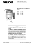
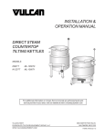
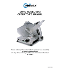
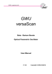
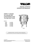
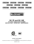
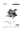
INSTALLATION &
OPERATION MANUAL
ELECTRIC
STATIONARY AND
TILTING KETTLES
MODEL
30
60
90
120
0
30
Hg
vac
150
psi
MIL
K20EL
136073
K40EL
136074
K60EL
136075
K20ETL
136077
K40ELT
136078
K60ELT
136079
K40EL
For additional information on Vulcan-Hart or to locate an authorized parts
and service provider in your area, visit our website at www.vulcanhart.com
VULCAN-HART
DIVISION OF ITW FOOD EQUIPMENT GROUP, LLC
WWW.VULCANHART.COM
3600 NORTH POINT BLVD.
BALTIMORE, MD 21222
FORM 35457 (10-09)
ELECTRIC STATIONARY KETTLES
IMPORTANT FOR YOUR SAFETY
THIS MANUAL HAS BEEN PREPARED FOR PERSONNEL QUALIFIED TO
INSTALL ELECTRICAL EQUIPMENT, WHO SHOULD PERFORM THE INITIAL
FIELD START-UP AND ADJUSTMENTS OF THE EQUIPMENT COVERED BY THIS
MANUAL.
: Improper installation, adjustment,
alteration, service or maintenance can cause property
damage, injury or death. Read the INSTALLATION,
OPERATION and MAINTENANCE instructions
thoroughly before installing or servicing this equipment.
—2—
ELECTRIC STATIONARY KETTLES
CONTENTS
IMPORTANT FOR YOUR SAFETY ................................................................................................ 2
INSTALLATION, OPERATION AND MAINTENANCE OF
K20EL/ELT, K40EL/ELT AND K60EL/ELT ELECTRIC KETTLES ......................................... 4
GENERAL ................................................................................................................................... 4
MODEL CHART ......................................................................................................................... 4
DATA PLATE LOCATION .......................................................................................................... 4
INSTALLATION ................................................................................................................................. 5
UNPACKING ............................................................................................................................... 5
INSTALLATION CODES AND STANDARDS ........................................................................... 5
LOCATION .................................................................................................................................. 5
Stationary Kettle ................................................................................................................... 5
Tilting Kettle .......................................................................................................................... 5
MINIMUM CLEARANCE REQUIREMENTS and
RECOMMENDED FLOOR DRAIN LOCATIONS ..................................................................... 6
INSTALLATION PROCEDURE ................................................................................................. 6
Electrical Connection ........................................................................................................... 6
Electrical Specifications ...................................................................................................... 6
OPERATION .................................................................................................................................... 8
VENTING ..................................................................................................................................... 8
RESERVOIR JACKET WATER LEVEL CHECK ..................................................................... 8
DAILY OPERATION ................................................................................................................... 8
TILTING KETTLES ..................................................................................................................... 8
CONTROLS AND INDICATORS ............................................................................................... 8
CLEANING ........................................................................................................................................ 9
2" & 3" COMPRESSION VALVE CLEANING INSTRUCTIONS ............................................... 9
PLUG VALVE CLEAINING INSTRUCTIONS ........................................................................... 10
STAINLESS STEEL EQUIPMENT CARE AND CLEANING ................................................... 11
MAINTENANCE ............................................................................................................................. 13
VENTING .................................................................................................................................. 13
FILLING THE RESERVOIR JACKET ..................................................................................... 13
TROUBLESHOOTING .................................................................................................................. 14
SERVICE AND PARTS INFORMATION ...................................................................................... 15
—3—
ELECTRIC STATIONARY KETTLES
INSTALLATION, OPERATION AND MAINTENANCE
OF K20EL/ELT, K40EL/ELT AND K60EL/ELT
ELECTRIC KETTLES
DATA PLATE LOCATION
SAVE THESE INSTRUCTIONS
FOR FUTURE USE
The data plate stating the model number,
serial number and the electrical characteristics
is located on the back of Control Panel. The
National Board Data Plate is located on the
lower skirt.
GENERAL
Vulcan Steam Jacketed Kettles are produced
with quality workmanship and material. Proper
installation, usage and maintenance will result
in many years of satisfactory performance. It
is suggested that you thoroughly read this
entire manual and carefully follow all of the
instructions provided.
MODEL CHART
Model
Gallons Quarts
Liters
K20EL, K20ELT
20
80
76
K40EL, K40ELT
40
160
152
K60EL, K60ELT
60
240
227
Fig. 2 Data Plate Location
Fig. 1 Typical Stationary Kettle
—4—
ELECTRIC STATIONARY KETTLES
INSTALLATION
UNPACKING
LOCATION
This kettle was inspected before leaving the
factory. The transportation company assumes
full responsibility for safe delivery upon
acceptance of the shipment.
Stationary Kettle
Position the kettle in its final location. Check that
there are sufficient clearances for operating and
servicing the kettle, and proper clearance of the
cover when raised. The kettle draw-off valve
should be located near a floor drain.
Immediately after unpacking, check for
possible shipping damage. If kettle damage is
found, save the packaging material and
contract the carrier within 15 days of delivery.
Tilting Kettle
INSTALLATION CODES
AND STANDARDS
Position the kettle in its final installed location to
provide drainage directly below pour path, with
sufficient rear clearance from the wall to allow
the kettle to tilt completely without obstruction.
In the United States, Vulcan kettles must be
installed in accordance with:
1. State and local codes
2. NFPA Standard NFPA-96, Vapor Removal
from Cooking Equipment, latest edition,
available from the National Fire Protection
Association, Batterymarch Park, Quincy,
MA 02269
3. National Electrical Code (ANSI/NFPA
No.70, latest edition) available from the
National Fire Protection Association
(NFPA), Batterymarch Park, Quincy, MA
02269
In Canada, Vulcan kettles must be installed in
accordance with:
1. Local codes
2. Canadian Electrical Code (CSA C22.2
No.3, latest edition) available from the
Canadian Standards Association, 5060
Spectrum Way, Mississauga, Ontario,
Canada L4W 5N6
—5—
ELECTRIC STATIONARY KETTLES
MINIMUM CLEARANCE
REQUIREMENTS AND RECOMMENDED
FLOOR DRAIN LOCATIONS
INSTALLATION PROCEDURE
Level the kettle by making necessary
adjustments using the flanged feet.
No side and back clearance required, except
for operation and service requirements.
1. Place a spirit level on the rim of the kettle
with the cover open. Adjust the feet to level
the kettle left-to-right and front-to-back.
2. Mark anchoring hole locations through the
flanged feet.
3. With hole location marked, drill holes to
accommodate 5/16" studs.
4. Reposition the kettle.
5. Bolt the kettle down and apply an NSF
approved silicone sealant around the
bolt heads and flange making contact
with floor surface. Wipe off excess
sealant immediately.
Fig 3. Floor Drain Location
—6—
ELECTRIC STATIONARY KETTLES
ELECTRICAL CONNECTION
: Electrical and grounding connections must comply with applicable portions of the National Electric
Code and/or other local electrical codes.
Disconnect
electrical power to the
machine and follow Lockout/
Tagout procedures.
1. Open the control box.
2. Using the wiring diagram for reference,
connect electric supply to terminal block.
ELECTRICAL SPECIFICATIONS
Amperage per Line
MODEL
K20EL/ELT
kW
12
16
PHASE
Minimum
Circuit Ampacity
208V
240V
480V
208V
240V
480V
1
57.7
–
–
75
–
–
3
33.3
–
14.4
45
–
20
1
–
66.7
–
–
85
–
3
–
38.5
–
–
50
–
K40EL/ELT
K60EL/ELT
18
3
50.0
43.3
21.7
65
55
30
K40EL/ELT
K60EL/ELT
24
3
66.6
57.7
28.9
85
75
40
K60EL/ELT
33
3
91.6
79.4
39.7
115
100
50
—7—
ELECTRIC STATIONARY KETTLES
OPERATION
: The kettle and its parts
are hot. Use care when operating, cleaning or servicing the kettle.
30
60
90
120
0
30
Hg
vac
150
psi
VENTING
While the kettle is cold, check the vacuum/pressure
gauge. The gauge should be in the vacuum zone
measuring between 20 to 30 in. Hg (84 to 100kPa).
If not, there is air in the jacket and it must be
removed by venting for proper heating. Perform
the VENTING procedure located in the
MAINTENANCE section of this manual.
RESERVOIR JACKET
WATER LEVEL CHECK
During use, the reservoir water level must be
maintained high enough to submerge the
heating elements. If the low water light is
illuminated during use, perform the FILLING
THE RESERVOIR JACKET procedure located
in the MAINTENANCE section of this manual.
Fig. 4 Kettle Controls
CONTROLS AND INDICATORS
DAILY OPERATION
1. Press the power switch to the ON position.
2. Preheat the kettle by placing the thermostat
knob at Simmer/Boil (desired setting) and
wait until the temperature light cycles off.
Food products with milk or egg base should
be placed into a cold kettle before cooking.
Avoid sudden contact of these food
products to a hot kettle surface because
they stick to the surface.
CONTROL
FUNCTION
Vacuum
Pressure
Gauge
Indicates the vacuum (in
inches) and pressure
( in PSI) inside the
kettle jacket.
Thermostat
Knob
Regulates kettle temperature
from warm to a rolling boil.
Low Water
Indicator
(Red)
When lit, indicates
insufficient water in the
kettle jacket and the sensing
probe has interrupted power
supply to the controls and to
the heating element.
3. Pour the food to be cooked into the kettle.
Power ON/OFF Controls power to the kettle.
Switch
TILTING KETTLES
The low water indicator light (red) should not
be lit when kettle is in upright position during
operation. This light indicates that the elements
have been automatically shut off by the kettle’s
safety circuity. It is, however, normal for the
low water light (red light) to come on when the
kettle is in a tilited posistion.
—8—
Power ON
Indicator
(Amber)
When lit, indicates
machine on/powered.
Heater
Light (Amber)
When lit, indicates the
heating element is turned on.
ELECTRIC STATIONARY KETTLES
CLEANING
: The kettle and its
parts are hot. Use care when operating,
cleaning or servicing the kettle.
2. Thread the valve stem into bonnet till valve
can be pulled through bonnet.
NOTICE:
4. Install large nut hand tight.
3. Insert assembly into valve body.
Never spray the exterior of
the kettle or control box with
water under any condition.
Failure to comply will void
the warranty.
5. Install valve handle, lock washer and nut
onto the valve stem.
6. Turn valve handle clockwise until closed.
Do not overtighten.
The kettle interior and exterior should be
thoroughly washed after each use when a
different food is to be cooked next or when
cooking is completed for the day.
Daily After Use
Remove draw-off valve stem assembly for
cleaning.
1. Add water to the kettle for cleaning and to
prevent residue from drying and sticking to
the inside of the kettle.
1. Turn the valve handle counterclockwise
until it stops.
2. Loosen stuck-on food by allowing it to
soak at a low temperature setting.
2. Pull the valve handle back until it stops.
3. Turn large bonnet retaining nut
counterclockwise until the valve stem
assembly is loose.
Never use harsh or corrosive cleaning
chemicals.
Never scrape the inside of the kettle with
abrasive cleansers, metal tools or steel
scouring pads, which will scratch the surface,
spoil the appearance and make it more difficult
to thoroughly clean.
4. Pull the assembly straight out of the valve
body.
5. Remove the stem from the bonnet.
6. Wash valve body and steam assembly
with mild soap and water.
3. Add mild detergent and scrub the kettle
interior with a nylon brush.
7. Leave assembly apart to air dry.
4. Thoroughly rinse the interior and dry with a
soft cloth.
5. Rinse the exterior and dry with a soft cloth.
2" & 3" COMPRESSION VALVE
CLEANING INSTRUCTIONS
Fig. 6 Compression Valve
Daily Before Operation
Install draw-off valve assembly:
1. Apply PetroGel lubricant to valve stem
threads, “O” ring, rubber plug face and
large nut threads.
—9—
ELECTRIC STATIONARY KETTLES
PLUG VALVE CLEAINING
INSTRUCTIONS
NOTE:
Daily Before Operation
Install draw off valve plug:
1. Apply PetroGel lubricant to valve tapered
face.
1. Care should be taken not to
scratch, ding or dent the valve
plug to prevent valve leakage.
2. If multiple kettles are in use care
should be taken keep each plug
separate and returned to its
original valve body.
2. Holding the valve handle, slide the plug
down into the valve body.
3. Install the bottom washer, making sure to
align the key with the groove in the valve
plug.
4. Install the retaining ring and hand tighten.
Valve Plug
NOTE: If the valve is hard to open the ring has
been overtightened.
Daily After Use
Valve Body
Remove draw-off valve plug for cleaning.
1. Unscrew the retaining ring and remove it
and the bottom washer.
2. Pull the valve plug straight up to remove
from valve body.
Bottom Washer
3. Wash valve body, plug, washer and
retaining ring with mild soap and water.
Retaining Ring
4. Leave assembly apart to air dry.
Fig. 7 Plug Valve
— 10 —
ELECTRIC STATIONARY KETTLES
heated leave deposits behind that if left to sit, will
break down the passive layer and rust stainless
steel. Other deposits from food preparation and
service must be properly removed.
STAINLESS STEEL EQUIPMENT
CARE AND CLEANING
Contrary to popular belief, stainless
steels ARE susceptible to rusting.
Corrosion on metals is everywhere. It is
recognized quickly on iron and steel as
unsightly yellow/orange rust. Such metals are
called “active” because they actively corrode
in a natural environment when their atoms
combine with oxygen to form rust.
Stainless steels are passive metals because
they contain other metals, like chromium, nickel
and manganese that stabilize the atoms. 400
series stainless steels are called ferritic, contain
chromium, and are magnetic; 300 series
stainless steels are called austenitic, contain
chromium and nickel; and 200 series stainless,
also austenitic, contains manganese, nitrogen
and carbon. Austenitic types of stainless are not
magnetic, and generally provide greater
resistance to corrosion than ferritic types.
With 12-30 percent chromium, an invisible
passive film covers the steel’s surface acting as
a shield against corrosion. As long as the film is
intact and not broken or contaminated, the metal
is passive and stain-less. If the passive film of
stainless steel has been broken, equipment
starts to corrode. At its end, it rusts.
Chlorides are found nearly everywhere. They
are in water, food and table salt. One of the
worst chloride perpetrators can come from
household and industrial cleaners. So what
does all this mean? Don’t Despair!
Here are a few steps that can help prevent
stainless steel rust.
1. Use the proper tools.
When cleaning stainless steel products,
use non-abrasive tools. Soft cloths and
plastic scouring pads will not harm steel’s
passive layer. Stainless steel pads also
can be used but the scrubbing motion
must be in the direction of the
manufacturers’ polishing marks.
2. Clean with the polish lines
Some stainless steel comes with visible
polishing lines or “grain.” When visible
lines are present, always scrub in a motion
parallel to the lines. When the grain cannot
be seen, play it safe and use a soft cloth or
plastic scouring pad.
3. Use alkaline, alkaline chlorinated or
non-chloride containing cleaners.
While many traditional cleaners are loaded
with chlorides, the industry is providing an
ever-increasing choice of non-chloride
cleaners. If you are not sure of chloride
content in the cleaner used, contact your
cleaner supplier. If your present cleaner
contains chlorides, ask your supplier if they
have an alternative. Avoid cleaners
containing quaternary salts; it also can attack
stainless steel and cause pitting and rusting.
Enemies of Stainless Steel
There are three basic things which can break
down stainless steel’s passivity layer and
allow corrosion to occur.
1. Mechanical abrasion
2. Deposits and water
3. Chlorides
Mechanical abrasion means those things
that will scratch a steel surface. Steel pads,
wire brushes and scrapers are prime
examples.
4. Treat your water.
Water comes out of the faucet in varying degrees
of hardness. Depending on what part of the
country you live in, you may have hard or soft
water. Hard water may leave spots, and when
— 11 —
Though this is not always practical,
softening hard water can do much to
reduce deposits. There are certain filters
that can be installed to remove distasteful
and corrosive elements. To insure proper
water treatment, call a treatment specialist.
ELECTRIC STATIONARY KETTLES
5. Keep your food equipment clean.
6. Rinse, rinse, rinse.
Use alkaline, alkaline chlorinated or nonchloride cleaners at recommended strength.
Clean frequently to avoid build-up of hard,
stubborn stains. If you boil water in stainless
steel equipment, remember the single most
likely cause of damage is chlorides in the
water. Heating cleaners that contain chlorides
have a similar effect.
If chlorinated cleaners are used, rinse and
wipe equipment and supplies dry immediately. The sooner you wipe off standing
water, especially when it contains cleaning
agents, the better. After wiping equipment
down, allow it to air dry; oxygen helps maintain the stainless steel’s passivity film.
7. Never use hydrochloric acid (muriatic
acid) on stainless steel.
8. Regularly restore/passivate stainless
steel.
Recommended cleaners for specific situations
JOB
CLEANING AGENT
COMMENTS
Routine cleaning
Soap, ammonia,
detergent, Medallion
Apply with cloth or sponge
Fingerprints & smears
Arcal 20, Lac-O-Nu Ecoshine
Provides barrier film
Stubborn stains &
discoloration
Cameo, Talc, Zud,
First Impression
Rub in direction of polish lines
Grease & fatty acids,
blood, burnt-on-foods
Easy-off, De-Grease It Oven Aid
Excellent removal on all
finishes
Grease & oil
Any good commercial detergent
Apply with sponge or cloth
Restoration/Passivation
Benefit, Super Sheen
Review
1. Stainless steels rust when passivity (filmshield) breaks down as a result of scrapes,
scratches, deposits and chlorides.
5. Soften your water. Use filters and softeners
whenever possible.
Stainless steel rust starts with pits and
cracks.
6. Wipe off cleaning agent(s) and standing
water as soon as possible. Prolonged
contact causes eventual problems.
3. Use the proper tools. Do not use steel
pads, wire brushes or scrapers to clean
stainless steel.
To learn more about chloride-stress corrosion
and how to prevent it, contact the equipment
manufacturer or cleaning materials supplier.
4. Use non-chlorinated cleaners at
recommended concentrations. Use only
chloride- free cleaners.
Developed by Packer Engineering, Naperville, Ill., an
independent testing laboratory.
Provided courtesy of NAFEM.
2
— 12 —
ELECTRIC STATIONARY KETTLES
MAINTENANCE
VENTING
FILLING THE RESERVOIR JACKET
The vacuum pressure gauge measuring zone
should be between 20 to 30 in.Hg (84 to
100kPa). If the vacuum pressure is not within
this range, perform the following:
2. Set the temperature control to the max
heat setting. Let the kettle heat until it
cycles off.
Before adding water to the reservoir, the water
supply should be analyzed to ensure that
hardness is no greater than 2.0 grains per
gallon and the pH level is within the range of
7.0 to 8.5. Water which fails to meet these
standards should be treated, or use ionized
distilled water with sodium. Equipment failure
caused by inadequate water quality is not
covered under warranty. To fill the reservoir
jacket, perform the following:
3. Pull the pressure relieve valve D-ring to
relieve pressure for 10 seconds.
1. Set the thermostat and power switch to
OFF position.
4. Turn kettle off and let cool. Check for a
correct vacuum pressure of 20 to 30 in. Hg
(84 to 100kPa). If the reading is not correct,
repeat steps 1 through 3.
2. Release any pressure by the O-ring on the
pressure relief valve. Then remove the 1/2 "
plug on the back of the kettle.
1. With the kettle empty, place the power
switch to the ON position.
30
0
30
Hg
vac
60
3. Insert a funnel into the fill valve and add 3
or 4 ounces of water.
4. Replace and properly tighten the 1/2" plug.
90
120
150
5. Turn on the kettle.
psi
30
0
30
Hg
vac
60
If the low water light turns on, turn off the unit
and repeat steps 3 and 4. If low water light is
off, follow the venting procedure (see
VENTING) to vent air from reservoir.
90
120
150
psi
MODEL
Fig. 5 Rear of Kettle
— 13 —
TOTAL
DISTILLED WATER
REQUIREMENTS
K20EL / K20ELT
1.25 gallons (4.1)
K40EL / K40ELT
2.0 gallons (6.5)
K60EL / K60ELT
2.1 gallons (7.4)
ELECTRIC STATIONARY KETTLES
TROUBLESHOOTING
PROBLEM
Unit not Heating
POSSIBLE CAUSES / SUGGESTED CORRECTIVE ACTION
ON/OFF switch OFF / ON/OFF switch ON.
Thermostat not on / Turn thermostat on.
No power / Check power supply.
Water level too low / Add water.
Malfunctioning power ON/OFF switch / Contact Authorized
Vulcan-Hart Service Provider.
Malfunctioning thermostat / Contact Authorized Vulcan-Hart
Service Provider.
Contactors not connecting heating element to power source / Contact
Authorized Vulcan-Hart Service Provider.
Unit not heating to
desired temperature
Thermostat not on / Turn thermostat on.
Malfunctioning thermostat / Contact Authorized Vulcan-Hart
Service Provider.
Draw valve is leaking
Check and clean any food residue with an extremely fine emery cloth.
Replace the “O” ring.
— 14 —
ELECTRIC STATIONARY KETTLES
SERVICE AND PARTS INFORMATION
To obtain service and parts information concerning this unit, contact the Vulcan-Hart Service
Agency in your area (refer to listing supplied with the steamer), or contact the Vulcan-Hart Service
Department at the address or phone number shown on the front cover of this manual.
Parts and service are also available at www.vulcanhart.com.
— 15 —
ELECTRIC STATIONARY KETTLES
(10-09)
— 16 —
PRINTED IN U.S.A.