1
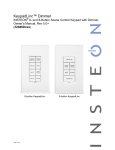
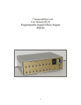
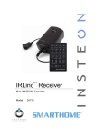
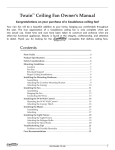
KeypadLinc Schedule Timer INSTEON® Keypad Schedule Timer Model : 2484DST6 (Dimmer) 2485S (On/Off Switch) KeypadLinc Schedule Timer Owner’s Manual TABLE OF CONTENTS ABOUT KEYPADLINC SCHEDULE TIMER .................................................................................................................3 Key KeypadLinc Schedule Timer Features ................................................................................................................3 What is Included with KeypadLinc Schedule Timer....................................................................................................4 WHAT IS INSTEON? .....................................................................................................................................................4 INSTALLATION .............................................................................................................................................................4 Tools You Will Need ...................................................................................................................................................4 Preparing to Install KeypadLinc Schedule Timer........................................................................................................4 Identifying the Electrical Wires in your Home .............................................................................................................5 Installing KeypadLinc Schedule Timer .......................................................................................................................6 Installing KeypadLinc Schedule Timer in a Multi-Way Circuit ....................................................................................7 USING KEYPADLINC SCHEDULE TIMER ................................................................................................................. 12 Using the Buttons to Control Scenes ....................................................................................................................... 12 Entering Time in KeypadLinc Schedule Timer ......................................................................................................... 12 Setting the Clock in KeypadLinc Schedule Timer..................................................................................................... 13 Programming a Timer in KeypadLinc Schedule Timer ............................................................................................. 13 Using the Air Gap ..................................................................................................................................................... 14 ON-LEVELS AND RAMP RATES (KeypadLinc Dimmer only) ................................................................................. 14 About On-Levels and Ramp Rates........................................................................................................................... 14 Setting the On-Level on KeypadLinc Dimmer .......................................................................................................... 14 Setting the Ramp Rate on KeypadLinc Dimmer ....................................................................................................... 15 CONTROLLING INSTEON RESPONDERS FROM KEYPADLINC SCHEDULE TIMER ........................................... 16 Linking KeypadLinc Schedule Timer to an INSTEON Responder ............................................................................ 16 Unlinking an INSTEON Responder from KeypadLinc Schedule Timer .................................................................... 16 CONTROLLING KEYPADLINC SCHEDULE TIMER FROM AN INSTEON CONTROLER ........................................ 17 Linking an INSTEON Controller to KeypadLinc Schedule Timer .............................................................................. 17 Unlinking KeypadLinc Schedule Timer from an INSTEON Controller ...................................................................... 17 CREATING INSTEON SCENES .................................................................................................................................. 17 ADVANCED FEATURES ............................................................................................................................................ 18 Multi-Linking and Multi-Unlinking.............................................................................................................................. 18 Cross-Linking INSTEON Devices............................................................................................................................. 19 Viewing/Editing a Scene’s On/Off Timers ................................................................................................................ 20 Disabling a Scene’s On/Off Timers .......................................................................................................................... 20 Restoring Power to KeypadLinc Schedule Timer ..................................................................................................... 20 Resetting KeypadLinc Schedule Timer to its Factory Default Settings..................................................................... 21 X10 PROGRAMMING OPTIONS................................................................................................................................. 21 Setting the X10 Address .......................................................................................................................................... 21 Removing the X10 Address...................................................................................................................................... 21 ABOUT INSTEON ....................................................................................................................................................... 22 Using Dual-Band INSTEON Devices to Upgrade Your Network .............................................................................. 22 Important Note about INSTEON Networks; Split Single-Phase vs. 3-Phase Installation.......................................... 22 Further Enhancing Reliability ................................................................................................................................... 22 ADDITIONAL RESOURCES ....................................................................................................................................... 22 TROUBLESHOOTING ................................................................................................................................................. 23 SPECIFICATIONS, CERTIFICATION, AND WARRANTY .......................................................................................... 25 Specifications ........................................................................................................................................................... 25 Certification .............................................................................................................................................................. 25 ETL / UL Warning (KeypadLinc Dimmer only).......................................................................................................... 25 Limited Warranty ...................................................................................................................................................... 26 KeypadLinc Schedule Timer Owner’s Manual ABOUT KEYPADLINC SCHEDULE TIMER KeypadLinc Schedule Timer presents you with an elegant and stylish way to control a wired-in light and add timer capabilities to your existing INSTEON devices. Use the buttons on KeypadLinc to create and control customized lighting “scenes” within your home. Or send commands from another INSTEON device and you’ll be able to conveniently and remotely control KeypadLinc. Scene buttons On/Off buttons (load controlling) Set button (push) Air gap (pull) Wallplate (sold separately) Key KeypadLinc Schedule Timer Features Feature After installation, setup is easy – Links to other INSTEON devices in minutes Load control Dimmer On/Off Switch X X Standard incandescent up to 600 Watts X Standard inductive up to 13 Amps, incandescent up to 480 Watts X X X X X Schedules on and off timers for up to five scenes Responds to and controls other INSTEON devices as well as X10 devices Indicates INSTEON setup mode activity and operational states with a Status LED and beeper Dims the load up to 32 brightness levels Changes brightness at 32 Ramp Rates Stores setup state in memory so settings aren’t lost during power outages Wires into standard J-boxes (requires a NEUTRAL connection) Supports “virtual” 3-, 4-, or more-way circuits with multiple KeypadLincs Two-year warranty Page 3 of 26 X X X X X X X X X X KeypadLinc Schedule Timer Owner’s Manual What is Included with KeypadLinc Schedule Timer • 1x - KeypadLinc Schedule Timer – INSTEON Keypad Schedule Timer with Dimmer or On/Off Switch • 2x - Mounting screws • 4x - Wire nuts • 1x - Quick-Start Guide WHAT IS INSTEON? Since its inception in 2005, INSTEON has become a best-selling home-control networking technology, offering more reliability and flexibility than any other home management system on the market. INSTEON systems are simple, reliable, and affordable. Simple, because each device takes mere minutes to install. Reliable, because every INSTEON device works as a network repeater, ensuring your commands will not be lost. Affordable, because INSTEON can be integrated into any number of devices easily and at a very low cost. An INSTEON home grows in value with each added INSTEON device, making life more convenient, safe, and fun. How Does INSTEON Work? What makes INSTEON the most reliable home automation network is its dual-mesh network. INSTEON devices use both radio frequency (RF) signals and the home’s existing wiring to talk to each other. In an INSTEON network, every INSTEON device also acts as a repeater, receiving and sending every message to all other devices in the network. So by integrating more INSTEON devices you will strengthen the network and ensure no commands will be lost. No central controller or networking setup is required with an INSTEON network. Simply install your devices and then use a series of button presses or taps to Link your devices together. Throughout this Owner’s Manual, you may see the terms “Controller” or “Responder”. These generic INSTEON terms refer to the components of an INSTEON scene, and are used on a scene-by-scene basis. • Controller – sends INSTEON commands to other devices • Responder – reacts to commands sent out by another INSTEON device An INSTEON device may act as a Controller, Responder, or sometimes both. INSTEON networks are also extremely secure. Each INSTEON device is assigned a unique INSTEON ID, so unless neighbors or would-be hackers have access to your particular device’s INSTEON ID, they won’t be able to control your home, even if they are using similar products. INSTALLATION Tools You Will Need • Screwdrivers (both Flathead and Phillips) • Voltage tester • Wire cutter / stripper Preparing to Install KeypadLinc Schedule Timer CAUTION Read and understand these instructions before installing and retain them for future reference. KeypadLinc is intended for installation in accordance with the National Electric Code and local regulations in the United States or the Canadian Electrical Code and local regulations in Canada. Use indoors only. KeypadLinc is not designed nor approved for use on power lines other than 120V 60Hz, single phase. Attempting to use KeypadLinc on non-approved power lines may have hazardous consequences. Prior to installing KeypadLinc, please review the entire installation procedure and take the following precautions: • Use indoors or in a properly insulated and weatherproof electrical box only Page 4 of 26 KeypadLinc Schedule Timer Owner’s Manual • Be sure that you have turned off the circuit breaker or removed the fuse for the circuit you are installing KeypadLinc in. Installing KeypadLinc with the power on will expose you to dangerous voltages. • Connect only copper or copper-clad wire to KeypadLinc • KeypadLinc may feel warm during operation. The amount of heat generated is within approved limits and poses no hazards. To minimize heat buildup, ensure that the area surrounding the rear of KeypadLinc has adequate ventilation by clearing away excess insulation. • KeypadLinc requires a small amount of power to operate, which it receives from a connection to the NEUTRAL electrical wire (usually white). If you are replacing a standard mechanical switch with KeypadLinc, the switch you are replacing may not normally have a connection to the NEUTRAL wire. However, most junction boxes will contain a NEUTRAL wire that you can connect KeypadLinc to. If the junction box does not contain a NEUTRAL wire, please contact the INSTEON Gold Support Line or consult an electrician. • Each KeypadLinc is assigned a unique INSTEON ID, which is printed on the device’s label. It is recommended that you prepare a list of all the devices you are installing, including their INSTEON ID and their location (e.g., 01.F7.G5, Mike’s bedroom light). It is only necessary to know the INSTEON IDs if you will be using optional automation software (such as Smarthome’s HouseLinc) to program and control your devices. However, it will be helpful to have a list of your devices, should you choose to use automation software later. Creating a list prior to installation will prevent you from needing to re-open all the junction boxes and fixtures to determine the INSTEON IDs. • Don’t use KeypadLinc to control an electrical outlet because non-dimmable or inductive loads may be plugged into it Additional KeypadLinc Dimmer precautions • KeypadLinc can be mounted in a single or multiple-ganged junction box. However, KeypadLinc will control 200W less for each immediately adjacent dimmer installed. For example, a 600W load control will become 400W when another dimmer is installed to the immediate right or left. Use a triple-gang box with a nondimming INSTEON on/off switch in the center to avoid de-rating the load control. • To reduce the risk of overheating and possible damage to other equipment, use KeypadLinc to control 110V incandescent lamps only. Dimming an inductive load, such as a fan or transformer, could cause damage to the dimmer, the load device, or both. If the manufacturer of the load device does not recommend dimming, use a non-dimming INSTEON on/off switch. USER ASSUMES ALL RISKS ASSOCIATED WITH DIMMING AN INDUCTIVE LOAD. IMPORTANT! If you are not knowledgeable about and comfortable with electrical circuitry, you should have a qualified electrician install KeypadLinc for you. If you have any questions, please consult an electrician or call: INSTEON Gold Support Line 800-762-7845 Identifying the Electrical Wires in your Home To install KeypadLinc, you will need to identify the following four wires: • LINE - usually black, may also be called HOT or LIVE, carries electricity into the switch • LOAD - usually black, red, or blue, carries electricity away from the switch and to the load • NEUTRAL - usually white, may not previously be connected to mechanical switches • GROUND - bare copper wire You can usually identify the wires based on color. If you are unable to distinguish the wires by color alone (LINE and LOAD wires are often the same color), you will need a voltage tester to find the LINE wire: 1) Be sure no exposed wires are touching anything and then enable power to the switch from the circuit breaker or fuse panel 2) Use a voltage tester to find the wire that carries 110 – 120 Volts. This is the LINE wire. 3) Once you have identified the LINE wire, be sure to disable power at the circuit breaker before resuming installation If you are having difficulties identifying wires, consult an electrician to help you. Page 5 of 26 KeypadLinc Schedule Timer Owner’s Manual Installing KeypadLinc Schedule Timer 1) At the circuit breaker or fuse panel, disconnect the power for all of the circuits in the switch junction box. Verify that the power is off by trying to turn on the lights controlled by the switches. 2) Remove the wallplate from the switch you are replacing. Then, unscrew the switch itself and pull it out from the junction box. 3) Disconnect the wires from the switch you are replacing. If the wires cannot be detached by unscrewing them, cut the wires where they enter the switch, and then strip ½ inch of insulation off the ends. 4) If you are installing KeypadLinc into a standard 2-way circuit (where only one switch controls the load), follow the diagram below to identify and connect the LINE, LOAD, NEUTRAL, and GROUND wires on KeypadLinc. Be sure you have correctly identified the wires in the switch junction box before connecting them. See Identifying the Electrical Wires in your Home. Wiring Diagram NOTE: Home’s wire color and wire location may vary If you are installing KeypadLinc into a multi-way circuit (where more than one switch controls the load), see Installing KeypadLinc Schedule Timer in a Multi-Way Circuit. 5) After you have connected all of the wires, ensure that the wire connectors are firmly attached and that there is no exposed copper except for the GROUND wire 6) Gently place KeypadLinc into the junction box, orienting the unit with the Set button on the bottom, and screw into place 7) Enable power to the switch from the circuit breaker or fuse panel 8) Test that KeypadLinc is working properly by tapping its On and Off buttons 9) Reinstall the wallplate Page 6 of 26 KeypadLinc Schedule Timer Owner’s Manual Installing KeypadLinc Schedule Timer in a Multi-Way Circuit Understanding Multi-Way Circuits If more than one switch controls a single set of lights (called a load), the switches are part of a multi-way circuit. A 3-way circuit uses two switches to control a load, a 4-way circuit uses three switches, and so forth. Most homes have one or more 3-way circuits, with two switches located in hallways, stairwells, or two different entrances to a room. Less commonly found are circuits that are 4-way or above. Here is how a typical wired-in 3-way circuit (with two switches) works: A wired-in 4- or more-way circuit (with three or more switches) has additional switches added in the middle of the circuit. In the 4-way diagram below, the additional switch (Switch 3+) is shown in two different positions, since wiring can vary from home to home. Page 7 of 26 KeypadLinc Schedule Timer Owner’s Manual Using KeypadLinc Schedule Timer in Virtual Multi-Way Circuits Once KeypadLincs have been installed, you can create a virtual multi-way circuit to control a single load. Rather than connect each switch directly to the load, virtual multi-ways use INSTEON messaging to control the load. Two components make up a virtual multi-way circuit: • KeypadLinc Primary – wired directly to the load • KeypadLinc Secondaries – other KeypadLincs in the circuit, but not wired to the load The diagram below shows how to wire a 3-way circuit with two KeypadLincs. After the KeypadLincs have been wired-in, you create a virtual multi-way by Cross-Linking each of the desired KeypadLincs to one another (see Cross-Linking INSTEON Devices). NOTE: Actual location of the wires on KeypadLinc may differ with device revision or model. KeypadLinc Secondary KeypadLinc Primary • The KeypadLinc Primary’s LOAD wire gets connected to the actual load that is being controlled • The LOAD wire for any KeypadLinc Secondaries will not be connected to anything, so cap those LOAD wires off with a wire nut • Notice that one of the TRAVELER wires (TRAVELER 1, the red one) is not used, so you will cap it off at both ends with a wire nut. The other TRAVELER (TRAVELER 2, the black one) you will convert to a LINE wire. In the junction box where the KeypadLinc Secondary is, connect TRAVELER 2 to the existing LINE and also to the KeypadLinc Secondary’s LINE wire. In the junction box at the other end, you will connect TRAVELER 2 to the KeypadLinc Primary’s LINE wire. • All KeypadLincs, whether they are Primaries or Secondaries, must be connected to NEUTRAL and to GROUND. Note that the switches you are replacing will not normally have a connection to NEUTRAL. If there is no NEUTRAL wire in the junction box, please consult an electrician or call INSTEON Gold Support Line at 800-762-7845. Page 8 of 26 KeypadLinc Schedule Timer Owner’s Manual Step-by-Step Instructions for Installing Multi-Way KeypadLincs When replacing a 3-way mechanical switch, each switch will have three wires connected to it from the wall box. Four-way or greater circuits will have four wires connected to the switches in the center of the circuit. For this tutorial, we will follow the most commonly used wire colors for homes in North America. 1) Find the LINE wire. Your first task is to find out which switch junction box is the one where the electricity comes into the circuit. This box will contain the LINE wire. • Disable power at the circuit breaker or fuse panel • Pull all the switches in the multi-way circuit out of their junction boxes. Each switch should have three wires connected to it. If the circuit is 4-way or greater, some of the switches will have four wires. • Disconnect the wires from the old switches. If the wires cannot be detached by unscrewing them, cut the wires where they enter the switch and then strip ½ inch of insulation off the ends. • Making sure that none of the wires are touching anything and turn the electricity back on • Using a volt meter or voltage tester, individually test each wire for voltage. When you measure between 110 and 120 Volts AC, that wire is the LINE wire (usually black). • The other two wires (usually black and red) are the TRAVELERS and go to the next junction box. TRAVELER wires are usually in the same cable sheath. • Turn off the electricity to resume installation 2) Connect the KeypadLinc Secondary’s LINE wire. The KeypadLinc that will be the Secondary goes in the junction box where you found the LINE wire. Connect the LINE wire that you found, the black TRAVELER, and the KeypadLinc Secondary’s black LINE wire all together with a single wire nut. 3) Cap the other TRAVELER wire. The other TRAVELER wire (usually red) will not be used, so put a wire nut on the end of it. 4) Cap the red LOAD wire from the KeypadLinc Secondary. Put a wire nut on the end of the KeypadLinc Secondary’s LOAD wire to ensure that it won’t connect to anything. 5) Connect the KeypadLinc Secondary’s NEUTRAL wire. Locate the group of NEUTRAL wires (usually white) in the rear of the box. The old switch should not have been connected to the NEUTRAL wires, but KeypadLinc requires this connection in order to draw a small amount of power for itself. Connect the KeypadLinc Secondary’s white NEUTRAL wire to the other NEUTRAL wires with a wire nut. Page 9 of 26 KeypadLinc Schedule Timer Owner’s Manual 6) Connect the KeypadLinc Secondary’s GROUND Wire. Connect the bare copper GROUND wire to the other GROUND wire in the junction box. 7) Install additional KeypadLinc Secondaries. If you have a 4-way or greater switching circuit, see Special Treatment for 4- or More-Way Circuits at the end of this section. 8) Identify the wires for the KeypadLinc Primary. The KeypadLinc Primary is the KeypadLinc that will actually control the load. In the junction box where you will install the KeypadLinc Primary, find the wire that carries power from the switch to the lights. This wire, called the LOAD wire, is commonly red. In the same junction box, there will also be the two TRAVELER wires from the first box, often both in the same cable sheath. Identify the TRAVELER wire (black) that you connected the LINE wire to in the first junction box. If you’re not sure which is the TRAVELER wire connected to the LINE wire, you can use the same method described in step 1 to find it. Turn on the power (taking the same precautions) and use a voltmeter to find the wire with 110 – 120 Volts AC on it. Make sure the power is turned off again before proceeding. 9) Connect the KeypadLinc Primary’s LINE wire. Use a wire nut to connect the TRAVELER wire (usually black) that you identified as connected to the LINE wire to the KeypadLinc Primary’s black LINE wire. 10) Cap the other TRAVELER wire. The other TRAVELER wire (usually red) will not be used, so put a wire nut on the end of it. 11) Connect the KeypadLinc Primary’s LOAD wire. Use a wire nut to connect the LOAD wire (usually red) to the KeypadLinc Primary’s red LOAD wire. 12) Connect the KeypadLinc Primary’s NEUTRAL and GROUND wires. Repeat steps 5 and 6 with the KeypadLinc Secondary. 13) Complete installation. Return to Installing KeypadLinc Schedule Timer and continue on from step 5. 14) Cross-Link the KeypadLincs. See Cross-Linking INSTEON Devices to complete the virtual 3-way circuit. Page 10 of 26 KeypadLinc Schedule Timer Owner’s Manual Special Treatment for 4- or More-Way Circuits If your lighting circuit includes more than two switches controlling a single set of lights, those extra switches will have four wires connected to them. Two of the wires are TRAVELERS from the preceding switch and the other two are TRAVELERS to the next switch in the chain. You will be converting the black TRAVELER wires to the LINE wires and replacing the old 4-wire switches with KeypadLinc Secondaries. 1) Connect the KeypadLinc Secondary’s LINE Wire. Use a wire nut to connect both black TRAVELER wires to the KeypadLinc Primary’s black LINE wire. 2) Cap the two unused TRAVELERS. The other two TRAVELER wires (usually red) will not be used, so put wire nuts on the ends of them. 3) Cap the red LOAD wire from the KeypadLinc Secondary. Put a wire nut on the end of the KeypadLinc Secondary’s LOAD wire to ensure that it won’t connect to anything. 4) Connect the KeypadLinc Secondary’s NEUTRAL and GROUND wires. Repeat steps 5 and 6 of Step-by Step Instructions for Installing Multi-Way KeypadLincs. Page 11 of 26 KeypadLinc Schedule Timer Owner’s Manual USING KEYPADLINC SCHEDULE TIMER Using the Buttons to Control Scenes On/Off Buttons The load (device wired-in to KeypadLinc) can be controlled by using the dedicated On/Off buttons. If you wish to include the load in a scene, you must use the dedicated On/Off buttons. Scene Buttons The A, B, C, and D buttons are considered “Scene buttons”, meaning you can use any of the buttons on KeypadLinc to create INSTEON scenes. Each button will control its own scene, only sending commands to devices Linked specifically to that button. When the LED of a button is on, the scene has been activated, or turned on. When the scene has been deactivated, the LED will turn off. For KeypadLinc with Dimmer only: The load and dimmable Responders will behave differently depending on how you activate the buttons, depending on whether you tap, double-tap, or press & hold a button to activate/deactivate a scene. Non-dimming Responders will only turn full-on or full-off, no matter what method you use. Button On Off A, B, C, or D Tap Ramp to On-Level Ramp to Off Ramp to On-Level/Off Double-tap Full-bright instantly Full-off instantly Full-bright instantly/Fulloff instantly Press & hold Brighten until released Dim until released Brighten/Dim until released Entering Time in KeypadLinc Schedule Timer KeypadLinc Schedule Timer uses military time (24 hour, e.g., 3:24 = 15:24) to control its scenes. When entering Programming Mode for initial setup, the time defaults to 0:00. Tapping the A, B, C, and D buttons will increase the time by the following increments: 10 hours 1 hour 1 minute 10 minutes For example, if you are entering a time of 13:22, you would tap the A button once, B button three times, C button twice, and D button twice. Hours Tap A +10 Tap B +1 Tap B +1 Tap B +1 13 : : Minutes Tap C +10 Tap C +10 Tap D +1 Tap D +1 22 Page 12 of 26 KeypadLinc Schedule Timer Owner’s Manual Setting the Clock in KeypadLinc Schedule Timer 1) Set KeypadLinc to Programming Mode by pressing & holding the Set button for 3 seconds The LED will cycle between the On, A, and B buttons 2) Tap the A button to enter Clock Setup Mode KeypadLinc will beep and the On button will begin blinking (if the clock has already been programmed, KeypadLinc will flash the A, B, C, and D buttons to show the clock time) 3) Once the On button begins blinking continuously, tap the A, B, C, and D buttons to enter the desired time. See Entering Time in KeypadLinc Schedule Timer. KeypadLinc will beep with each button tap 4) Tap the On button to accept the entered time KeypadLinc will beep and the LED will cycle between the On, A, and B buttons 5) Tap the On button to exit Clock Setup Mode KeypadLinc will beep and the On or Off button will turn on solid based on the state of the load Scene button LEDs will turn on solid if the scenes are activated Programming a Timer in KeypadLinc Schedule Timer NOTE: If the same ON or OFF timer is used for more than one scene button, the timers will activate one minute apart from one another. For example, if you program both the A and B buttons with an OFF time for 09:00, A will turn off at 09:00 and B will turn off at 09:01. Buttons will activate in the following order, when applicable: On, Off, A, B, C, and D. 1) Set KeypadLinc to Programming Mode by pressing & holding the Set button for 3 seconds The LED will cycle between the On, A, and B buttons 2) Tap the B button to enter Timer Setup Mode KeypadLinc will beep and the LED will cycle between the On, A, B, C, and D buttons 3) Tap the Scene button you would like to program the timer into (On, A, B, C, or D) KeypadLinc will beep and the LED will cycle between the On and Off buttons 4) Tap the A, B, C, and D buttons to enter the desired ON time. See Entering Time in KeypadLinc Schedule Timer. KeypadLinc will beep with each button tap 5) Tap the On button accept the ON time KeypadLinc will beep and the B button will turn on solid while the On button begins blinking 6) Tap the A, B, C, and D buttons to enter the desired OFF time KeypadLinc will beep with each button tap 7) Tap the Off button to accept the OFF time KeypadLinc will beep and the B button will turn on solid while the Off button begins blinking 8) Tap the Off button to return to Programming Mode KeypadLinc will beep and the LED will cycle between the On, A, and B buttons 9) Tap the On button to exit Programming Mode and return to normal operation KeypadLinc will beep and the On or Off button will turn on solid based on the state of the load Scene button LEDs will turn on solid if the scenes are activated Page 13 of 26 KeypadLinc Schedule Timer Owner’s Manual Using the Air Gap 1 Pulling the Set button at the bottom of the paddle out as far as it will go (about /8 inch) opens mechanical contacts that remove all power from KeypadLinc and the load that it controls. “Air gapping” can be useful for replacing bulbs or any other time you want the controlled circuit to be unpowered. Because the KeypadLinc settings are stored in non-volatile memory, setup information will not be lost when the device unpowered. BE CAREFUL If you press the Set button in too far when you undo the air gap, you might inadvertently reset KeypadLinc to its factory default settings. Make sure to only push the Set button in until its top is flush with the wallplate. ON-LEVELS AND RAMP RATES (KeypadLinc Dimmer only) About On-Levels and Ramp Rates The On-Level is the brightness that the load will go to when you turn it on. The On-Level is adjustable from off to 100% brightness. The default is 100%. The Ramp Rate is the amount of time it will take the load to go from full-off to full-on or from full-on to fulloff. The Ramp Rate is adjustable from 0.1 to 9 seconds to ramp between full-on and full-off and vice versa. The default is 0.1 seconds. You can set up a local On-Level/Ramp Rate for the load, which is activated by tapping the On/Off buttons on KeypadLinc. Or set up remote On-Levels/Ramp Rates that are activated when you tap and On/Off or Scene button on a Linked Controller. A single KeypadLinc is capable of storing different On-Levels and Ramp Rates for each Linked Controller (or each button if it is a multi-scene Controller). On-Levels and Ramp Rates are locked in separately and can be set up in any order. When you do the lock-in, the most recently set On-Level and Ramp Rate are locked in together. Setting the On-Level on KeypadLinc Dimmer 1) Use the On and Off buttons on KeypadLinc to adjust the light to the desired brightness 2) Once the desired brightness has been achieved, tap the Set button on KeypadLinc KeypadLinc will beep 3) Test the On-Level settings by tapping the On/Off buttons on KeypadLinc KeypadLinc will respond appropriately The local On-Level has now been set. If you would like to set up a Controller to set KeypadLinc to the programmed On-Level, proceed to Linking an INSTEON Controller to KeypadLinc Schedule Timer and begin from step 2. NOTE: If any LEDs are flashing, you held the Set button down too long. Holding down the Set button for 3 seconds places KeypadLinc into Programming Mode. Programming Mode will time out after 4 minutes of inactivity. To manually exit Programming Mode, tap the On button. Page 14 of 26 KeypadLinc Schedule Timer Owner’s Manual Setting the Ramp Rate on KeypadLinc Dimmer NOTE: Setting the Ramp Rate does not change/affect the On-Level brightness. 1) Setting the Ramp Rate is done using the brightness level as an indicator for how fast KeypadLinc should ramp. Use the On and Off buttons on KeypadLinc to set the brightness to a brighter level for a faster Ramp Rate or dimmer for a slower Ramp Rate. 100% bright corresponds to a 0.1-second Ramp Rate and full-off corresponds to a 9-second Ramp Rate. The following table gives the approximate relationship between the brightness you set in this step and the Ramp Rate you get. Approximate Brightness Level 90-100% 77-87% 65-74% 52-61% 39-48% 26.35% 13-23% 1-10% Less than 1% Ramp Rate in seconds 0.1 0.2 0.3 0.5 2.0 4.5 6.5 8.5 9.0 NOTE: If the load is ramping to less than full brightness, then the time it will take will be proportionately less. For instance, if the load is going to halfbrightness, the time it will take for a given Ramp Rate will be halved. 2) Once you reach the desired brightness (Ramp Rate), double-tap the Set button on KeypadLinc KeypadLinc will beep 3) Test the Ramp Rate settings by tapping the On/Off buttons on KeypadLinc KeypadLinc will respond appropriately The local Ramp Rate has now been set. If you would like to set up a Controller to set KeypadLinc to the programmed Ramp Rate, proceed to Linking an INSTEON Controller to KeypadLinc Schedule Timer. NOTE: If the load flashes twice, you didn’t double-press the Set button fast enough and the KeypadLinc OnLevel was actually set up twice. Reset the correct On-Level and try setting the Ramp Rate again from step 1. Page 15 of 26 KeypadLinc Schedule Timer Owner’s Manual CONTROLLING INSTEON RESPONDERS FROM KEYPADLINC SCHEDULE TIMER Linking KeypadLinc Schedule Timer to an INSTEON Responder To use KeypadLinc as an INSTEON Controller, follow these steps to Link KeypadLinc and an INSTEON Responder (the device you wish to control with KeypadLinc) together. Refer to the Responder’s Owner’s Manual for detailed instructions on how to properly install and Link it to KeypadLinc. The following will work for the most common INSTEON devices: 1) At the Responder, set it to the state you wish to be activated from KeypadLinc (turn it on if you wish it to be on or off if you wish it to be off when KeypadLinc activates the scene, set On-Levels/brightness levels, Ramp Rates, etc.) • If the Responder is a multi-scene device, tap the Scene button you wish to control until its LED is in the desired state (on or off) 2) Set KeypadLinc to Linking Mode by pressing & holding the desired button until it beeps (10 seconds) The button’s LED will begin blinking You will have 4 minutes to complete the next step before Linking Mode automatically times out. BE CAREFUL - Any accidental button presses will exit Linking Mode early. 3) Press & hold the Responder’s Set button for 3 seconds KeypadLinc will beep and the button’s LED will stop blinking and turn on solid 4) Confirm that Linking was successful by tapping the button you just Linked to on KeypadLinc on and then off The Responder will respond appropriately 5) If you wish to Link additional devices to the same button on KeypadLinc, either repeat steps 1-4 with each Responder or see Multi-Linking and Multi-Unlinking Unlinking an INSTEON Responder from KeypadLinc Schedule Timer If you are no longer going to use an INSTEON Responder that has been Linked to KeypadLinc, it is very important that you Unlink it. Otherwise, KeypadLinc will retry any commands repetitively, thus slowing down the system. The following will work for the most common INSTEON devices: 1) If the Responder is a multi-scene device, tap the Scene button you wish to remove control from until its LED illuminates 2) Set KeypadLinc to Linking Mode by pressing & holding the desired button until it beeps (10 seconds) The button’s LED will begin blinking 3) Set KeypadLinc to Unlinking Mode by pressing & holding the desired button until it beeps again (10 seconds) The button’s LED will continue blinking 4) Press & hold the Responder’s Set button for 3 seconds KeypadLinc will beep and the button’s LED will stop blinking and turn on solid 5) Confirm that Unlinking was successful by tapping the button you just Unlinked from on KeypadLinc on and then off The Responder will no longer respond Page 16 of 26 KeypadLinc Schedule Timer Owner’s Manual CONTROLLING KEYPADLINC SCHEDULE TIMER FROM AN INSTEON CONTROLER Linking an INSTEON Controller to KeypadLinc Schedule Timer To use KeypadLinc as an INSTEON Responder, follow these steps to Link KeypadLinc and a Controller together. Refer to the Controller’s Owner’s Manual for detailed instructions on how to properly install and Link it to KeypadLinc. The following will work for the most common INSTEON devices: 1) Set the load or desired Scene button to the state you wish to activate from the Controller (i.e., tap to turn the LED on or off) 2) Set the Controller to Linking Mode. (For most Controllers, press & hold an On or Scene button for 10 seconds or the Set button for 3 seconds.) You will have 4 minutes to complete the next step before Unlinking Mode automatically times out. 3) Press & hold the button on KeypadLinc you wish to control until it beeps (10 seconds) The button’s LED will flash once and then turn on solid 4) Confirm that Linking was successful by tapping the button you just Linked to on the Controller KeypadLinc will respond appropriately Unlinking KeypadLinc Schedule Timer from an INSTEON Controller If you are going to discontinue using KeypadLinc, it is very important that you Unlink it from any Linked Controllers. Otherwise, the Controllers will retry any commands repetitively, thus slowing down the system. The following will work for the most common INSTEON devices: 1) Set the Controller to Unlinking Mode. (For most Controllers, press & hold an On or Scene button for 10 seconds twice or the Set button for 3 seconds twice.) You will have 4 minutes to complete the next step before Unlinking Mode automatically times out. 2) Press & hold the button you wish to Unlink until it beeps (10 seconds) The button’s LED will flash once and then turn on solid 3) Confirm that Unlinking was successful by tapping the button you just Unlinked from on the Controller KeypadLinc will no longer respond CREATING INSTEON SCENES INSTEON scenes let you activate dramatic lighting moods with the tap of just one button. For example, you can set all the lights in a scene to dim to 50% or turn certain lights on while turning others off, all with the tap of a button on a Controller. INSTEON scenes are very easy to set up – just Link more than one Responder to the same On/Off or Scene button on a Controller. Then, when you tap any of the Linked buttons on the Controller, all of the INSTEON devices Linked in the scene will respond as a group. To set up an INSTEON scene, you can individually Link each device to a Controller. Or save time and create multiple Links at once (see Multi-Linking and Multi-Unlinking). Page 17 of 26 KeypadLinc Schedule Timer Owner’s Manual ADVANCED FEATURES Multi-Linking and Multi-Unlinking Multi-Linking Multi-Linking Mode allows you to Link multiple Responders to a single Controller and quickly create an INSTEON scene. Once the Controller is in Multi-Linking Mode, you can Link any number of Responders, one right after the other. The following will work for the most common INSTEON devices: 1) Set each of the Responders to the state you wish to activate from the Controller • Turn the Responder on or off, set the brightness/On-Level and Ramp Rate, etc. • If the Responder is a multi-scene device (e.g., KeypadLinc), tap the desired Scene button until its LED is in the desired state (on or off) 2) Set the Controller to Linking Mode. (For most Controllers, press & hold the desired On or Scene button for 10 seconds or the Set button for 3 seconds.) 3) Tap the Set button on the Controller. If the Controller does not have a Set button, tap the same On or Scene button you used to put the Controller into Linking Mode. Multi-Linking Mode will automatically time out after 4 minutes of inactivity. 4) One at a time, press & hold each of the Responder’s Set buttons for 3 seconds. (For KeypadLinc Schedule Timers, press & hold the desired button.) 5) After you have Linked all the desired Responders, tap the Controller’s Set button to exit Multi-Linking Mode. If the Controller does not have a Set button, tap the same On or Scene button you used to put the Controller into Linking Mode. 6) Test that the INSTEON scene is working properly by tapping the button you just Linked to on the Controller Multi-Unlinking Multi-Unlinking Mode can be used to quickly remove devices from an INSTEON scene. You may remove as many of the Linked Responders from the scene as you would like. The following will work for the most common INSTEON devices: 1) Set the Controller to Unlinking Mode. (For most Controllers, press & hold the desired On or Scene button for 10 seconds twice or the Set button for 3 seconds twice.) 2) Tap the Set button on the Controller. If the Controller does not have a Set button, tap the same On or Scene button you used to put the Controller into Unlinking Mode. Multi-Unlinking Mode will automatically time out after 4 minutes of inactivity. 3) For each of the Responders you wish to Unlink, press & hold the Set button for 3 seconds. (If the Responder is a multi-scene device, tap the Scene button you wish to Unlink and then press & hold the Set button.) 4) After you have Unlinked the desired Responders, tap the Controller’s Set button to exit MultiUnlinking Mode. If the Controller does not have a Set button, tap the same On or Scene button you used to put the Controller into Unlinking Mode. 5) Test that you have removed the desired Responders from the INSTEON scene by tapping the button you just Unlinked from on the Controller Page 18 of 26 KeypadLinc Schedule Timer Owner’s Manual Cross-Linking INSTEON Devices Cross-Linking Two INSTEON Devices Cross-Linking devices allow you to track the on/off status of the load on all Linked INSTEON Responders. For this example we will use a primary device controlling the load and one secondary device in a virtual 3-way. They will be referred to as: the Primary Device (the device wired to the load or load-controlling) and the Secondary Device (the additional device in the circuit). 1) Link the Primary Device as a Controller of the Secondary Device: a) Set the Secondary Device to the desired state (i.e., on/off, set Ramp Rate and OnLevel/brightness level) b) Put the Primary Device into Linking Mode. (For most devices, press & hold an On or Scene button for 10 seconds or the Set button for 3 seconds.) c) Press & hold the Set button on the Secondary Device for 3 seconds • If the Secondary Device is a multi-scene device (e.g., KeypadLinc), tap the Scene button you wish to control until its LED illuminates and then press & hold the Set button for 3 seconds 2) Cross-Link the Secondary Device as a Controller of the Primary Device: a) Set the Primary Device to the desired state (i.e., on/off, set Ramp Rate and On-Level/brightness level) b) Put the Secondary Device into Linking Mode. (For most devices, press & hold an On or Scene button for 10 seconds or the Set button for 3 seconds.) c) Press & hold the Set button on the Primary Device for 3 seconds • If the Primary Device is a multi-scene device, tap the Scene button you wish to control until its LED illuminates and then press & hold the Set button for 3 seconds Upon successful completion, each device will now track the on/off status of the load (and the LEDs of the devices it has been Cross-Linked to). Cross-Linking More Than Two INSTEON Devices When you have more than two devices controlling a single load, you can the Multi-Linking feature to Link one device to multiple others in one step. To Cross-Link all the devices together, you will perform a series of MultiLinking circuits. For this example, we will use a primary device controlling the load and two secondary switches in a virtual 4way. They will be referred to as: the Primary Device (load-controlling), the Secondary Device 1, and the Secondary Device 2. 1) Start the circuit by setting the Primary Device to Linking Mode. (For most devices, press & hold the On or Scene button for 10 seconds or the Set button for 3 seconds.) 2) Tap the Set button on the Primary Device to set it to Multi-Linking Mode. If the Primary Device does not have a Set button, use the Same On or Scene you used to put the Primary Device into Linking Mode. 3) One at a time, press & hold the Set buttons on each of the Secondary Devices 4) To finish the circuit, tap the Set button on the Primary Device. If the Primary Device does not have a Set button, use the same On or Scene button you used to put the Primary Device into Linking Mode. 5) Create the next circuit by repeating steps 1-4, substituting the Secondary Device 1 for the Primary Device 6) Create the next circuit by repeating steps 1-4, substituting the Secondary Device 2 for the Primary Device Upon successful completion, each device in the above scenario will now track the on/off status on the load (and the LEDs of the devices it has been Cross-Linked to). Page 19 of 26 KeypadLinc Schedule Timer Owner’s Manual Viewing/Editing a Scene’s On/Off Timers 1) Set KeypadLinc to Programming Mode by pressing & holding the Set button for 3 seconds The LED will cycle between the On, A, and B buttons 2) Tap the B button to enter Timer Setup Mode KeypadLinc will beep and the LED will cycle between the On, A, B, C, and D buttons 3) Tap the Scene button you wish to view/edit timers for KeypadLinc will beep and the LED will cycle between the On and Off buttons 4) Tap either the On or Off button to view/edit the respective timer KeypadLinc will beep and flash the A, B, C, and D buttons to show the time queried. When complete, the Scene button will turn on solid and either the On or Off button will begin blinking If you wish to edit the timer: a) Tap the A, B, C, and D buttons to enter the desired time KeypadLinc will beep with each button tap b) To accept the new timer as an ON time, tap either the On button. Tap the Off button to accept the new timer as an OFF time. KeypadLinc will beep and the B button will turn on solid while the On or Off button begins blinking 5) To view/edit the other timer, tap the button (either On or Off) that is not blinking and repeat step 4. KeypadLinc will beep and flash the A, B, C, and D buttons to show the timer. When complete, the Scene button will turn on solid and either the On or Off button will begin blinking To return to Programming Mode, tap the blinking button (On or Off) KeypadLinc will beep and the LED will cycle between the On, A, and B buttons 6) Tap the On button to exit Programming Mode and return to normal operation KeypadLinc will beep and the On or Off button will turn on solid based on the state of the load Scene button LEDs will turn on solid if the scenes are activated Disabling a Scene’s On/Off Timers On/Off timers can only be reset to zero by performing a factory reset (see Resetting KeypadLinc Schedule Timer to its Factory Default Settings). However, timers can be disabled by setting them with an invalid time, such as 30:00. Restoring Power to KeypadLinc Schedule Timer KeypadLinc stores all of its settings, such as Links to other INSTEON devices, On-Levels/Ramp Rates, etc., with non-volatile memory. Because settings are saved in this non-volatile memory, they will not be lost in the event of a power failure. In the event of a power loss KeypadLinc will automatically return the load to the brightness level it had before power was interrupted. NOTE: The KeypadLinc clock will resume once power is restored. When power is interrupted, reset the time on to ensure timers go on and off as scheduled. See Setting the Clock in KeypadLinc Schedule Timer. Page 20 of 26 KeypadLinc Schedule Timer Owner’s Manual Resetting KeypadLinc Schedule Timer to its Factory Default Settings The factory reset procedure can be used to clear the KeypadLinc memory of all INSTEON Links, timers, programmed On-Levels and Ramp Rates, X10 addresses, etc. 1) If you are using a Controller to control KeypadLinc, be sure to Unlink it from the Controller. See Unlinking KeypadLinc Schedule Timer from an INSTEON Controller. 2) If you are using KeypadLinc to control any Responders, Unlink them from KeypadLinc. See Unlinking an INSTEON Responder from KeypadLinc Schedule Timer. 1 3) Gently pull the Set button out as far as it will go (about /8 inch) to remove all power from KeypadLinc The load and the KeypadLinc LEDs will turn off 4) Wait 10 seconds and then push the Set button all the way down, Continue to hold for 3 seconds and then release. KeypadLinc will beep as you press the Set button all the way in. A few seconds after you release the Set button, KeypadLinc will double-beep and the load will turn on. X10 PROGRAMMING OPTIONS KeypadLinc is X10 ready, meaning that it can respond to X10 commands from an X10 controller and send commands to X10 devices. However, to operate KeypadLinc in X10 mode, you must first set up an X10 address. As it ships from the factory or after a factory reset procedure, KeypadLinc will have not have an X10 address set up. Setting the X10 Address 1) Set KeypadLinc to Linking Mode by pressing & holding the desired button until it beeps (10 seconds) The button’s LED will begin blinking You will have 4 minutes to complete the next step before Linking Mode automatically times out. 2) Using an X10 controller, send the X10 address you want to assign and the ON command three times For example, to assign the address A1, you would send “A1 ON A1 ON A1 ON.” 3) Once KeypadLinc has received the sequence, it should exit Linking Mode KeypadLinc will beep and the button’s LED will stop blinking and turn on solid Removing the X10 Address If you are no longer going to control KeypadLinc with an X10 address, it is very important that you Unlink it. Otherwise, KeypadLinc will still respond to X10 commands and may cause KeypadLinc to turn on by itself. 1) Set KeypadLinc to Linking Mode by pressing & holding the desired button until it beeps (10 seconds) The button’s LED will begin blinking 2) Set KeypadLinc to Unlinking Mode by pressing & holding the desired button until it beeps again (10 seconds) The button’s LED will continue blinking You will have 4 minutes to complete the next step before Unlinking Mode automatically times out. 3) Using an X10 controller, send the X10 address you wish to remove and the ON command three times For example, to remove the address A1, you would send “A1 ON A1 ON A1 ON”. 4) Once KeypadLinc has received the sequence, it will exit Linking Mode KeypadLinc will beep and the button’s LED will stop blinking and turn on solid Page 21 of 26 KeypadLinc Schedule Timer Owner’s Manual ABOUT INSTEON Using Dual-Band INSTEON Devices to Upgrade Your Network What are phases? The majority of single-family homes in North America have two phases (or “legs”) of 110 Volts coming into their electricity panels. From the panel, they are distributed throughout the home, providing power to outlets and wall switches. These phases come together in some parts of the home to provide 220 Volts of power to large appliances, such as an electric oven or pool pump. Why do I need to bridge these phases? Single-band power line devices send commands via the home’s electricity, but only on a single phase. If the command is intended for a device on the opposite phase, there is a good chance the command will go unnoticed. Installing dual-band INSTEON devices, such as Access Points (#2443), on each phase will allow for devices to communicate between the two phases via RF. Dual-band INSTEON devices embody the full potential of a true INSTEON mesh network. Taking the power line band signal and working in conjunction with the RF band signal, its dual-band function plays out in two ways: • Phase bridger – a receiver of commands, reacting to and translating signals sent from one power phase to the opposite via RF • Signal repeater – a participant in an INSTEON network, repeating commands intended for other devices whether those commands are generated from RF or power line-only devices. To ensure reliability, every INSTEON device confirms that it has received a command. If a Controller does not receive this confirmation, it will automatically retransmit the command up to five times. While using at least one dual-band device is required when using an RF-only device, at least two dual-band devices are recommended in any INSTEON network to ensure reliable communication across two-phase home wiring systems. For larger applications, it is recommended to install at least one dual-band device for every 750 – 1,000 square feet. Search for dual-band INSTEON devices at: www.smarthome.com/dualband Important Note about INSTEON Networks; Split Single-Phase vs. 3-Phase Installation For the best INSTEON network performance, be sure you have properly installed at least two dual-band INSTEON devices. INSTEON has only been officially tested in a split single-phase residential environment but has been known to work in many 3-phase systems, where three dual-band devices are used (one on each phase). However, due to the potential complexity of its troubleshooting, the INSTEON Gold Support Line is unable to support INSTEON in 3-phase environments. Further Enhancing Reliability As signals travel via the power line or RF throughout the home, they naturally become weaker the farther they travel. The best way to overcome weakened signals is to increase the coverage of the mesh network by introducing more INSTEON devices. It is possible that some audio-video devices, computers, power strips, or other electrical equipment may attenuate INSTEON signals on the power line. You can temporarily unplug suspected devices to test whether the INSTEON signal improves. If it does, then you can plug in filters that will permanently fix the problem. ADDITIONAL RESOURCES Find home automation solutions, helpful tips, interactive demos, videos, user forums, and more at the Smarthome Learning Center: www.smarthome.com/learningcenter.html Page 22 of 26 KeypadLinc Schedule Timer Owner’s Manual TROUBLESHOOTING Problem Possible Cause Solution Make sure the circuit breaker is turned on. The LEDs on KeypadLinc are not turning on and won’t control the load. Make sure the air gap (Set button) is not pulled out. KeypadLinc may not be getting power. Check the junction box wires to ensure all connections are tight and no bare wires are exposed. Check the light fixture to ensure all connections are tight and no bare wires are exposed. The Controller or Responder might have been reset without Unlinking KeypadLinc from it. Re-Link KeypadLinc to the Controller or Responder. The Controller or Make sure two Access Points (#2443) or other dualResponder and KeypadLinc band INSTEON devices are properly installed to may be on opposite power bridge the two power line phases. line phases. KeypadLinc won’t Link or work with a Controller or Responder. The INSTEON signal may be too weak. Large appliances, such as refrigerators or air conditioners, may be producing electrical noise on the power line. Other electrical devices, such as computers, televisions, or power strips, may be absorbing the INSTEON signal. Add additional INSTEON devices or move around existing INSTEON devices. All INSTEON devices act as INSTEON network repeaters. Install a power line noise filter (#1626-10) to filter electrical noise and minimize signal attenuation. KeypadLinc does not enter Linking Mode when I press & hold the Set button. Unlike other KeypadLinc models, pressing & holding does not set KeypadLinc to Linking Mode (sets to Programming Mode instead). KeypadLinc is taking a long time to respond to a Controller. The Controller may be sending commands to a Responder that is no longer in use. Commands for the unused Responder are being resent and loading down the signal. Unlink any unused Responders from the Controller. HINT: If you are using home automation software, you can easily check scene membership and eliminate unnecessary Links. Responders are taking a long time to respond to KeypadLinc. KeypadLinc may be sending commands to a Responder that is no longer in use. Commands for the unused Responder are being resent and loading down the signal. Unlink any unused Responders from KeypadLinc. HINT: If you are using home automation software, you can easily check scene membership and eliminate unnecessary Links. Link KeypadLinc by pressing & holding the desired button until it beeps (10 seconds). If the above doesn’t work, perform a factory reset on the Controller. If the above doesn’t work, perform a factory reset. See Resetting KeypadLinc Schedule Timer to its Factory Default Settings. Page 23 of 26 KeypadLinc Schedule Timer Owner’s Manual Problem The load turned on by itself. Possible Cause Another Controller, a timer, or stray X10 signals could have triggered KeypadLinc. Solution Perform a factory reset. See Resetting KeypadLinc Schedule Timer to its Factory Default Settings. KeypadLinc can turn off a Responder, but The Responder may be nothing happens when I Linked at its off state. send an ON command from KeypadLinc. Re-Link the Responder to KeypadLinc, while the Responder’s load is on. See the Responder’s Owner’s Manual for more detailed Linking instructions. The Controller can turn off KeypadLinc, but KeypadLinc does not turn on when I send an ON command from the Controller. KeypadLinc may be Linked at its off state. Re-Link KeypadLinc to the Controller, while the load is on. See Linking an INSTEON Controller to KeypadLinc Schedule Timer. The timer’s on or off setting may not be correct. Verify the on and off timers. See Viewing a Scene’s On/Off Timers. Reset the timers if necessary. See Programming a Timer in KeypadLinc Schedule Timer. The KeypadLinc clock may be incorrect (possibly due to loss of power). Reset the clock. See Setting the Clock in KeypadLinc Schedule Timer. The scheduled event is not turning on or off at the proper time. KeypadLinc is locked up. A surge or excessive noise on the power line may have glitched it. Pull the Set button on KeypadLinc all the way out to air gap it and then push it back in until it is flush with the wallplate. If the above doesn’t work, perform a factory reset. See Resetting KeypadLinc Schedule Timer to its Factory Default Settings. Additional Troubleshooting for KeypadLinc Dimmer: Problem Possible Cause Solution The load does not appear to turn on or off right away. The Ramp Rate may be set too slow. Set a shorter Ramp Rate. See Setting the Ramp Rate on KeypadLinc Dimmer. The load only turns off when I tap a button on KeypadLinc but I can brighten and dim it. The On-Level may be set to Set a brighter On-Level. See the section Setting the fully-off or very dim. On-Level on KeypadLinc Dimmer. The load is buzzing when on or dim. The dimming component inside KeypadLinc “chops” the power line sine wave to reduce the power. KeypadLinc is getting warm to the touch. KeypadLinc will dissipate about 1 Watt per 100 Watts It is normal for wall dimmers controlled. Using metal junction boxes, removing to get warm (but not hot). insulation around the outside of the box, or controlling a smaller load can help lessen the heat. After wiring in KeypadLinc, the device lets out a continuous beep. KeypadLinc may be issuing an error beep because the device is wired incorrectly. The bulb filaments are vibrating. Use rough-service, 130 Volt or appliance-grade bulbs to reduce the noise. Run KeypadLinc in the “full-on” mode or switch to a non-dimming switch. Turn off the circuit breaker and try reinstalling KeypadLinc. If you are still experiencing an error beep, consult an electrician to help you install KeypadLinc. Page 24 of 26 KeypadLinc Schedule Timer Owner’s Manual Problem KeypadLinc trips the Arc Fault Circuit Interrupter (AFCI). Possible Cause The AFCI might be too sensitive. Solution Replace the AFCI with a less sensitive brand or model from a hardware store with a customer-friendly return policy. Testing has found that the following AFCI models work well with KeypadLinc: • GE 15 Amp Combination Arc Fault Breaker #THQL1115AFP2 • Murray 2-Pole Combination Type Arc Fault Circuit Interrupter #MP215AFCP Install a power line noise filter between the output and the load. There might be loose connections within the home’s wiring. Consult an electrician to check the wiring in the home. If you have tried these solutions, reviewed this Owner’s Manual, and still cannot resolve an issue you are having with KeypadLinc, please call: INSTEON Gold Support Line 800-762-7845 SPECIFICATIONS, CERTIFICATION, AND WARRANTY Specifications View specifications for KeypadLinc Schedule Timer with Dimmer at: www.smarthome.com/2484DST6.html View specifications for KeypadLinc Schedule Timer with On/Off Switch at: www.smarthome.com/2485S.html Certification This product has been thoroughly tested by ITS ETL SEMKO, a nationally recognized independent thirdparty testing laboratory. The North American ETL Listed mark signifies that the device has been tested to and has met the requirements of a widely recognized consensus of U.S. and Canadian device safety standards, that the manufacturing site has been audited, and that the manufacturer has agreed to a program of quarterly factory follow-up inspections to verify continued conformance. ETL / UL Warning (KeypadLinc Dimmer only) CAUTION: To reduce the risk of overheating and possible damage to other equipment, do not install this device to control a receptacle, a motor-operated appliance, a fluorescent lighting fixture, or a transformersupplied appliance. Gradateurs commandant une lampe a filament de tungstene – afin de reduire le risqué de surchauffe et la possibilite d’endommagement a d’autres materiels, ne pas installer pour commander une prise, un appareil a moteur, une lampe flourescente ou un appareil alimente par un transformateur. Page 25 of 26 KeypadLinc Schedule Timer Owner’s Manual Limited Warranty Seller warrants to the original consumer purchaser of this product that, for a period of two years from the date of purchase, this product will be free from defects in material and workmanship and will perform in substantial conformity to the description of the product in this Owner’s Manual. This warranty shall not apply to defects or errors caused by misuse or neglect. If the product is found to be defective in material or workmanship, or if the product does not perform as warranted above during the warranty period, Seller will either repair it, replace it, or refund the purchase price, at its option, upon receipt of the product at the address below, postage prepaid, with proof of the date of purchase and an explanation of the defect or error. The repair, replacement, or refund that is provided for above shall be the full extent of Seller’s liability with respect to this product. For repair or replacement during the warranty period, call the INSTEON Gold Support Line at 800-762-7845 with the Model # and Revision # of the device to receive an RMA# and send the product, along with all other required materials to: Smarthome, Inc. ATTN: Receiving Dept. 16542 Millikan Ave. Irvine, CA 92606-5027 Limitations The above warranty is in lieu of and Seller disclaims all other warranties, whether oral or written, express or implied, including any warranty or merchantability or fitness for a particular purpose. Any implied warranty, including any warranty of merchantability or fitness for a particular purpose, which may not be disclaimed or supplanted as provided above shall be limited to the two-year of the express warranty above. No other representation or claim of any nature by any person shall be binding upon Seller or modify the terms of the above warranty and disclaimer. Home automation devices have the risk of failure to operate, incorrect operation, or electrical or mechanical tampering. For optimal use, manually verify the device state. Any home automation device should be viewed as a convenience, but not as a sole method for controlling your home. In no event shall Seller be liable for special, incidental, consequential, or other damages resulting from possession or use of this device, including without limitation damage to property and, to the extent permitted by law, personal injury, even if Seller knew or should have known of the possibility of such damages. Some states do not allow limitations on how long an implied warranty lasts and/or the exclusion or limitation of damages, in which case the above limitations and/or exclusions may not apply to you. You may also have other legal rights that may vary from state to state. INSTEON Technology Patent U.S Patent No. 7,345,998, International patents pending © Copyright 2011 Smarthome, 16542 Millikan Ave., Irvine, CA 92606, 800-762-7845, www.smarthome.com Rev 06-03-2011 Page 26 of 26