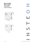
1
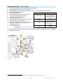
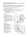
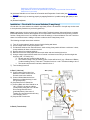
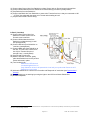
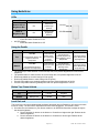
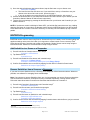
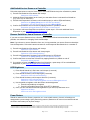
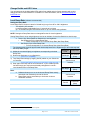
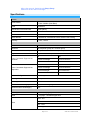
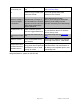
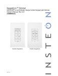
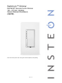
SwitchLinc™ Dimmer
INSTEON® Remote Control Dimmer
100 - 277VAC, 50/60Hz
Owners Manual (Dual-Band)
(#2478D)
Shown above with optional custom etching and screwless wallplates (sold separately)
Page 1 of 19
2478D - Rev: 1/21/2014 7:32 AM
About SwitchLinc 100 - 277VAC 50/60Hz Dimmer ................................................................................... 3
Features & Benefits .................................................................................................................................... 3
What’s in the box? ..................................................................................................................................... 3
Installation ................................................................................................................................................... 4
Identifying the Electrical Wires in your Home ............................................................................................ 4
Tools Needed ............................................................................................................................................ 4
Installing SwitchLinc – with 1 Switch ......................................................................................................... 5
Installation – Circuit with 2 Switches (3-way) ............................................................................................ 6
Installation – Circuit with 3 or more Switches (3-way/4-way) .................................................................... 7
Using SwitchLinc ........................................................................................................................................ 9
LEDs .......................................................................................................................................................... 9
Using the Paddle ....................................................................................................................................... 9
Button Tap / Press & Holds ....................................................................................................................... 9
Local On-Level .......................................................................................................................................... 9
INSTEON Programming ............................................................................................................................ 10
Add SwitchLinc to a Scene as a Responder ........................................................................................... 10
Remove SwitchLinc from a Scene as a Responder ................................................................................ 10
Add SwitchLinc to a Scene as a Controller ............................................................................................. 11
Remove SwitchLinc from a Scene as a Controller .................................................................................. 11
LED Brightness ........................................................................................................................................ 11
Power Restore ......................................................................................................................................... 11
X10 Programming.................................................................................................................................... 12
Advanced Features ................................................................................................................................... 12
Add Multiple Scene Responders (formerly “Multi-Linking Mode”) ........................................................... 12
Remove Multiple Scene Responders (formerly “Multi-Unlinking Mode”) ................................................ 12
Synchronized Scenes formerly “Cross-Linking” (2 switches; 3-way) (3 or more; 3-way/4-way) ............. 12
Air Gap..................................................................................................................................................... 13
Factory Reset .......................................................................................................................................... 13
Change Paddle and LED Colors ............................................................................................................. 14
Local Ramp Rate (software recommended)............................................................................................ 14
Additional Resources ............................................................................................................................... 15
Optional Accessories ............................................................................................................................... 15
Beeper Behavior ........................................................................................................................................ 15
Blink LED on INSTEON Traffic ................................................................................................................ 15
Air Gap..................................................................................................................................................... 15
Factory Reset .......................................................................................................................................... 15
Specifications ............................................................................................................................................ 16
Troubleshooting ........................................................................................................................................ 17
Certification and Warranty ....................................................................................................................... 19
Certification .............................................................................................................................................. 19
FCC & Industry Canada Compliance Statement ..................................................................................... 19
ETL / UL Warning (Safety Warning) ........................................................................................................ 19
Limited Warranty ..................................................................................................................................... 19
Page 2 of 19
2478D - Rev: 1/21/2014 7:32 AM
About SwitchLinc 100 - 277VAC 50/60Hz Dimmer
Congratulations on purchasing the SwitchLinc Dimmer. This version of the popular SwitchLinc line of
dimmers offers automatic 50/60Hz detection of the AC power frequency and flexible 100 - 277VAC
support allowing operation in a variety of electrical environments.
Features & Benefits
•
•
•
•
•
•
•
•
•
•
•
•
•
•
•
After installation, setup is easy – Add to Scenes with other INSTEON devices in minutes
International-friendly 50/60Hz auto-detect and flexible 100 - 277VAC power support
Controls all standard incandescent lamps, up to 600 watts
Adjustable to 32 dim levels
Adjustable on/off Ramp Rate speeds
Paddle has true rocker action – top is on or bright, bottom is off or dim
9-level LED bar shows brightness of lights
Status LED and beeper indicates INSTEON setup mode activity
Status LED provides gentle nightlight when switch is off
White LED bar color is changeable to green, blue, amber or red with optional kit
Responds to commands from X10 controllers and sends X10 commands to X10 devices
Wires in like a standard wall switch (but also requires a Neutral connection)
Supports SwitchLinc "virtual" 3-way, 4-way circuits
White paddle and trim frame is changeable to ivory, almond, black, brown or gray with optional kit
Two-year warranty
LED Bar
Brightness
Indicator
Paddle top
(On/Bright)
Paddle Bottom
(Off/Dim)
Trim Frame
Wallplate
(sold separately)
Set Button (push)
Air Gap (pull)
What’s in the box?
•
•
SwitchLinc Dimmer
Four wire nuts
Page 3 of 19
2478D - Rev: 1/21/2014 7:32 AM
•
Quick-Start Guide
Installation
CAUTIONS AND WARNINGS
Read and understand these instructions before installing and retain them for future reference.
This product is intended for installation in accordance with the National Electric Code and local regulations in the United States or
the Canadian Electrical Code and local regulations in Canada. Use indoors only. This product is not designed or approved for use
on power lines other than single-phase voltages between 100 – 277VAC, 50/60Hz., single phase. Attempting to use this product on
non-approved power lines may have hazardous consequences.
Recommended installation practices:
•
Use only indoors or in an outdoor rated box
•
Be sure that you have turned off the circuit breaker or removed the fuse for the circuit you are installing this product into.
Installing this product with the power on will expose you to dangerous voltages.
•
Connect using only copper or copper-clad wire
•
This product may feel warm during operation. The amount of heat generated is within approved limits and poses no hazards.
To minimize heat buildup, ensure the area surrounding the rear of this product is as clear of clutter as possible.
•
To reduce the risk of overheating and possible damage to other equipment, do not use this product to control Loads in excess
of the specified maximum(s) or, install in locations with electricity specifications which are outside of the product’s
specifications. If this device supports dimming, please note that dimming an inductive Load, such as a fan or transformer,
could cause damage to the dimmer, the load bearing device, or both. If the manufacturer of the load device does not
recommend dimming, use a non-dimming INSTEON on/off switch. USER ASSUMES ALL RISKS ASSOCIATED WITH
DIMMING AN INDUCTIVE LOAD.
Identifying the Electrical Wires in your Home
•
•
•
•
Line - usually Black, may also be called HOT, LIVE or Power, carries 100 - 277VAC electricity into the wall box
Neutral - usually White commonly daisy chained from box to box usually appearing as a White wire bundle
Load – usually Black, Blue, or Red (from a separate cable jacket)
Ground - Bare wire or metal fixture (if grounded)
IMPORTANT!
•
Each INSTEON product is assigned a unique INSTEON ID, which is printed on the product’s label. Please take note for future
reference
•
If you have any difficulties or questions, consult an electrician. If you are not knowledgeable about, and comfortable with
electrical circuitry, you should have a qualified electrician install the product for you.
Tools Needed
•
•
Slotted screwdriver
Wire cutter / stripper
•
•
Phillips screwdriver
Voltage Meter
Page 4 of 19
2478D - Rev: 1/21/2014 7:32 AM
Installing SwitchLinc – with 1 Switch
1)
2)
3)
4)
5)
6)
7)
8)
9)
10)
11)
12)
13)
Turn off circuit breaker(s) or remove fuse(s) feeding wall box
Use a voltage meter to verify that power is off
Remove wallplate from the switch and unscrew switch you are replacing and gently pull out
1
Disconnect wires from switch
SwitchLinc Wire
Wall Box Wires
Turn breaker(s) back on
Ground
Use a voltage meter to identify Line and Load
(commonly Bare,
wires which connected to the switch
Bare copper
Green wire or Green
Identify Neutral and Ground wires
screw)
Turn breakers(s) back off
Neutral
Connect wires as per Table A/Fig. 1(confirm firm
White
(commonly White)
attachment with no exposed wire)
Load
Gently place SwitchLinc into wall box, orienting
Red
(Light, commonly
unit with the LED bar on left. Then, screw
Black)
SwitchLinc into place.
Line (100 – 277V to
Turn breaker(s) back on
Black
Ground)
SwitchLinc’s LED bar and connected
light will turn on
Verify SwitchLinc is working properly by tapping SwitchLinc’s paddle turning light (load) on and Table
off A
Reinstall the wallplate
Fig 1
1
If the wires cannot be detached by unscrewing them, cut the wires where they enter the switch, then strip ½” of insulation off the ends
Page 5 of 19
2478D - Rev: 1/21/2014 7:32 AM
Installation – Circuit with 2 Switches (3-way)
Circuits with 2 switches are called 3-way circuits. Both switches in a 3-way circuit need to be replaced by
SwitchLincs (and/or KeypadLincs).
Note: 3-way circuits require a pair of wires called Travelers between joining wall boxes to operate.
INSTEON switches, dimmers and keypads do not require both Traveler wires for 3-way circuits to
function. Simply wire one to Line, Neutral and Load; the other(s) to Line and Neutral. Use one Traveler to
share Line between boxes. Adding both SwitchLincs to a Scene creates a virtual 3-way circuit.
1)
2)
3)
4)
5)
6)
Turn off circuit breaker(s) and/or remove fuse(s) feeding wall boxes
Use a voltage meter to verify that power is off
Pull both switches from their wall boxes, each existing 3-way switch will have no less than 3 wires
Remove wires from existing switches
Make sure wires are safely separated from each other and turn breaker(s) back on
Using a voltage meter measure each wire to Ground in both boxes until you find the single wire
supplying 100 - 277VAC (Line)
a. We will now refer to that location as box 1
b. The other box will have the Load wire. That will be box 2
7) Turn breaker(s) back off
In Box 1 (Line box)
8) Connect bare Ground wire from the
SwitchLinc to bare Ground wire or Ground
screw in wall box
9) Connect White Neutral wire from SwitchLinc
to Neutral wire(s) in wall box (usually white)
10) Using a wire nut, cap the Red wire from
SwitchLinc
11) Connect Black wire from Switch Linc to 100 277VAC Line wire in wall box (usually Black)
along with one Traveler wire running between
boxes (preferably Black). Note color of
Traveler you are using as this will carry Line
voltage to box 2.
12) Cap unused Traveler
In Box 2 (Load box)
13) Connect bare Ground wire from
SwitchLinc to bare Ground wire or
Ground screw in wall box
14) Connect White Neutral wire from
SwitchLinc to Neutral wire(s) in wall
box (usually White)
15) Connect Red wire from SwitchLinc to
Load wire (usually Black)
16) Connect Black wire from SwitchLinc to
same color Traveler from box 1
carrying 100 - 277VAC Line (usually
Black)
17) Cap unused Traveler wire
18) With the LED bar on the left, gently
place both SwitchLincs into the
junction boxes and screw in place
19) Turn breaker(s) On
Page 6 of 19
2478D - Rev: 1/21/2014 7:32 AM
SwitchLinc’s LED bar and connected light will turn on
Only SwitchLinc in box 2 will operate the Load until you synchronize Scenes to both
SwitchLincs in next step
20) Add both SwitchLincs to a Scene as a Controller and Responder of each other (see Synchronized
Scenes)
21) Verify SwitchLinc(s) are working properly by tapping SwitchLinc’s paddle turning light (load) on and
off
22) Reinstall wallplates
Installation – Circuit with 3 or more Switches (3-way/4-way)
Circuits with 3 or more switches are called 3-way/4-way circuits. All switches in 3-way/4-way circuits need
to be replaced by SwitchLincs (and/or KeypadLincs).
Note: 3-way/4-way circuits require a pair of wires called Travelers between joining wall boxes to operate.
INSTEON switches, dimmers and keypads do not require both Traveler wires for 3-way/4-way circuits to
function. Simply wire one to Line, Neutral and Load; the other(s) to Line and Neutral. Use one Traveler to
share Line between boxes. Adding to a Scene creates a virtual 3-way/4-way circuit.
The following example shows three switches
1) Turn off circuit breaker(s) and/or remove fuse(s) feeding wall boxes
2) Use a voltage meter to verify that power is off
3) Pull all three switches from their wall boxes, each existing 3-way switch will have a minimum 3 wires;
4-way switches will have a minimum 4 wires
4) Remove wires from existing switches
5) Make sure wires are safely separated from each other and turn breaker(s) back on
6) Using a voltage meter measure each wire to Ground in all three boxes until you find the single wire
supplying 100 - 277VAC (Line)
a. We will now refer to that location as box 1
b. The location having 2 sets of matching pairs of wires will be box 2 (e.g. 2 Reds and 2 Blacks,
or other matching colors). These are 2 Travelers from box 1 and 2 Travelers leading to box 3.
c. The last box will have the Load wire, that will be box 3
7) Turn breaker(s) back off
In Box 1 (Line box)
8) Connect bare Ground wire from
SwitchLinc to bare Ground wire or
Ground screw in the wall box
9) Connect White Neutral wire from
SwitchLinc to Neutral wire(s) in wall
box (usually white)
10) Cap Red wire from SwitchLinc
11) Connect Black wire from SwitchLinc to
100 - 277VAC Line wire in wall box
(usually Black) along with one Traveler
wire running between boxes
(preferably Black). Note color of
Traveler you are using as this will carry
Line voltage to box 2.
12) Cap unused Traveler wire
In Box 2 (Traveler box)
Page 7 of 19
2478D - Rev: 1/21/2014 7:32 AM
13)
14)
15)
16)
Connect bare Ground wire from SwitchLinc to bare Ground wire or Ground screw in the wall box
1
Connect White Neutral wire from SwitchLinc to Neutral wire(s) in wall box (usually White)
Cap Red wire from the SwitchLinc
Connect the Black wire from SwitchLinc to same color Traveler from box 1 that you connected to 100
- 277VAC Line along with the same color Traveler wires leading to box 3
17) Cap the last unused Traveler wire(s)
In Box 3 (Load box)
18) Connect bare Ground wire from
SwitchLinc to bare Ground wire or
Ground screw in wall box
19) Connect White Neutral wire from
SwitchLinc to Neutral wire(s) in wall
box (usually White)
20) Connect Red wire from SwitchLinc to
Load wire (usually Black)
21) Connect Black wire from SwitchLinc to
the 100 - 277VAC Line Traveler from
box 2 (Line Traveled from box 1
through 2 into 3, usually Black)
22) Cap unused Traveler wire
23) With the LED bar on the left, gently
place both SwitchLincs into the junction
boxes and screw in place
24) Turn breaker(s) On
SwitchLincs' LED bar and
connected light will turn on
Only SwitchLinc in box 3 will operate the Load until you synchronize Scenes on all 3
SwitchLincs in next step
25) Add each SwitchLinc to a Scene as a Controller and Responder of each other (see Synchronized
Scenes)
26) Verify SwitchLincs are working by turning the light on and off from all three SwitchLincs
27) Reinstall wallplates
1
If Neutral is not available in this box; use other unused Traveler from box 1 to carry Neutral to box 2. Label and mark any differently colored wire being connected to Neutral
with a piece of white tape to flag it as Neutral.
Page 8 of 19
2478D - Rev: 1/21/2014 7:32 AM
Using SwitchLinc
LEDs
•
•
LED
Status
Meaning
Bottom LED of
Brightness Bar
On
SwitchLinc
powered up
load off
LEDs on
Brightness Bar
On
Level of load
brightness
load on
On LED
Off LED
On LED (White)
o Illuminated when SwitchLinc is On
Off LED (White)
o Illuminated when SwitchLinc is Off
Using the Paddle
Paddle
Top
Tap
Double-tap
Press & hold begin
Press & hold end
Turn On
Connected load
quickly comes
On to full bright
& Scene
Responders
Connected load
gradually brightens &
start brightening Scene
Responders
Connected load &
Scene Responders
stop brightening
Connected load
quickly turns Off
& Scene
Responders
Connected load
gradually dims & Start
dimming Scene
Responders
Connected load &
Scene Responders
stops dimming
Connected load ramps to set
brightness & Scene
Responders
Turn Off
Bottom
•
•
•
•
•
•
Connected load ramps to
full Off & Scene Responders
Tap paddle top to make load turn on at local ramp rate, from present brightness to local On-level
brightness
Tap paddle bottom to make load turn off at local ramp rate, from present brightness to full Off
Double-tap paddle top to make load go full On quickly
Double-tap paddle bottom to make load go full Off quickly
Press & hold paddle top to gradually brighten load from present brightness to full On
Press & hold paddle bottom to gradually dim load from present brightness to full Off
Button Tap / Press & Holds
Paddle
Tap
Double-Tap
Press & Hold
Top
Ramp to On-Level
Fast On
Brighten
Bottom
Ramp to Off
Fast Off
Dim
Local On-Level
The Local On-Level is the brightness that the light(s) physically wired to SwitchLinc will come on at when
turned on locally. The On-Level is adjustable from off to 100% brightness. The default is 100%.
1) Use either the local buttons on your dimmer module or an INSTEON Controller to adjust the light to
the desired brightness
a. Press & hold the On button on the dimmer or Controller to brighten the light. Release at the
desired brightness.
b. Press & hold the Off button on the dimmer or Controller to dim the light. Release at the
desired brightness.
Page 9 of 19
2478D - Rev: 1/21/2014 7:32 AM
2) Once the desired brightness has been achieved, tap the Set button on your dimmer once
SwitchLinc will (Beep)
a. The local On-Level has now been set. If you would like to set up a Controller to set your
dimmer to the above On-Level as well, proceed to step 3.
b. If you do not wish to set up the On-Level to an INSTEON Controller, skip to step 4.
3) Choose the desired button on your INSTEON Controller and Add a Scene to your dimmer (see the
Controller's Owner's Manual for Add a Scene instructions)
4) Test the On-Level settings by pressing the On/Off buttons on your dimmer and Controller you just
Added a Scene to
NOTE: If the dimmer module is blinking its Status LED, you held the Set button down too long. Holding
down the Set button for 3 seconds is an alternate way to place the INSTEON dimmer into Scene Mode.
Scene Mode will time out after 4 minutes of inactivity. To manually exit Scene Mode, tap top or bottom
paddle.
INSTEON Programming
INSTEON remote control is done using Scenes. Scenes allow you to instantly “recall” favorite lighting and
appliance settings at the touch of a button (or in response to central control or even a sensor). Each
Scene has at least one Controller and at least one Responder. Simple Scenes can be setup using the
instructions below. Software is recommended for setup of larger Scenes.
Add SwitchLinc to a Scene as a Responder
1
1) Press & hold Scene Controller button until it beeps
Controller’s LED will blink
2) Tap SwitchLinc On
Load will turn on
3) Press & hold SwitchLinc’s Set button until it double-beeps
SwitchLinc will (Beep)-(Beep)
2
Controller’s LED will stop blinking and it will (Beep)-(Beep)
4) Confirm Scene addition was successful by tapping On then Off on Controller’s Scene button
SwitchLinc will respond appropriately
Remove SwitchLinc from a Scene as a Responder
If you want to remove SwitchLinc from a Scene(s) as a Responder follow instructions below. Whenever
possible, use software for managing Scene memberships.
Note: If you choose to remove SwitchLinc from use, it is important that you remove Scene memberships
from all Controllers. Otherwise, Controllers will retry commands repetitively, creating network delays.
Follow the instructions below for each Scene Controller that SwitchLinc is a member of.
3
1) Press & hold Controller’s Scene button until Controller beeps
Controller’s LED will blink
2) Press & hold Scene button until Controller beeps again
Controller’s LED will continue blinking
3) Tap SwitchLinc On
Load will turn on
4) Press & hold Set button on SwitchLinc until it double-beeps
SwitchLinc’s LED will flash once
Controller’s LED stops blinking
5) Confirm Scene removal was successful by tapping Controller button with the Scene you just removed
SwitchLinc will no longer respond
1
2
3
If the Controller does not have a beeper, wait until its LED begins blinking
Most models
For devices without beepers hold until its LED begins blinking (this may take 10+ seconds)
Page 10 of 19
2478D - Rev: 1/21/2014 7:32 AM
Add SwitchLinc to a Scene as a Controller
Follow the steps below to control a Scene (one or more INSTEON devices) from a SwitchLinc paddle
1)
2)
3)
5)
6)
Press & hold SwitchLinc’s Set button until it beeps
SwitchLinc’s LED will blink
Adjust the Scene Responder(s) to the “state” you want when Scene is activated from SwitchLinc
1
(e.g., 50%, 25% or even OFF)
Press & hold Responder’s Set button until it double-beeps (or until its LED/Load flashes)
2
SwitchLinc will (Beep)-(Beep) and its LED will stop blinking
3
Responder’s LED will stop blinking and it may (Beep)-(Beep)
Confirm Scene addition was successful by tapping SwitchLinc’s paddle on and off
Responder will toggle between the Scene’s on level and off
If you wish to add more Responders to the Scene, repeat steps 1-5 for each additional Scene
Responder or (see Add Multiple Scene Responders)
Remove SwitchLinc from a Scene as a Controller
If you want to remove SwitchLinc from a Scene(s) as a Controller follow instructions below. Whenever
possible, use software for managing Scene memberships.
Note: If you choose to remove SwitchLinc from use, it is important that you remove Scene memberships
from all Responders. Follow the instructions below for each Responder that SwitchLinc is a member of.
1) Press & hold SwitchLinc’s Set button until it beeps
SwitchLinc’s LED will blink
2) Press & hold SwitchLinc’s Set button until it beeps again
SwitchLinc’s LED will begin blinking
3) Press & hold Responder’s Set button until it double-beeps (or LED blinks)
SwitchLinc will (Beep)-(Beep) and its LED will stop blinking
4) Confirm that Scene removal was successful by tapping SwitchLinc’s paddle on and off
Responder will not respond
5) If you wish to remove multiple Responders from SwitchLinc, repeat steps 1-5 for each additional
Responder or (see Remove Multiple Scene Responders)
LED Brightness
1)
2)
3)
4)
5)
Press & hold SwitchLinc’s Set button until it beeps (3 seconds)
SwitchLinc’s LED will begin blinking
Press & hold Set button until it beeps again (3 seconds)
SwitchLinc’s LED will continue blinking
Press & hold Set button until it beeps a third time (3 seconds)
SwitchLinc’s LED will stop blinking
SwitchLinc’s Status LED will illuminate at current LED brightness level
Use the paddle to brighten or dim the LEDs to desired brightness
a. Press & hold paddle top to brighten
b. Press & hold paddle bottom to dim (fully OFF for dimmest)
Once you have reached the desired brightness for your LEDs, tap Set button once
SwitchLinc will beep
LED’s now set to new brightness level
Power Restore
SwitchLinc stores all of its Scenes, properties, etc. in non-volatile memory. As such, all settings are
retained after a power outage. Upon power being restored, SwitchLinc will return its connected load and
all LEDs to their states prior to power outage.
1
2
3
If the Responder is a multi-Scene device such as a KeypadLinc, tap the Scene button you wish to control until its LED is in the desired Scene state (on or off)
If either the SwitchLinc or Responders LED continues to blink, the addition failed. Tap the device’s Set button until LED stops blinking and try again.
If either the SwitchLinc or Responders LED continues to blink, the addition failed. Tap the device’s Set button until LED stops blinking and try again.
Page 11 of 19
2478D - Rev: 1/21/2014 7:32 AM
X10 Programming
Instructions on setting X10 primary address and Scene addresses can be found online:
http://www.smarthome.com/insteon-x10-programming.html
Advanced Features
Add Multiple Scene Responders (formerly “Multi-Linking Mode”)
1) Press & hold SwitchLinc’s Set Button until it beeps
SwitchLinc’s LED will blink
2) Tap SwitchLinc’s Set Button
LED will continue blinking
3) For each Responder you are adding
a. Adjust the Responder to desired Scene state
b. Press & hold Responder’s Set button until it beeps (or LED flashes)
SwitchLinc will (Beep)-(Beep)
4) After all Responders have been added, tap SwitchLinc’s Set Button
SwitchLinc’s LED will stop blinking
5) Confirm Scene addition was successful by tapping SwitchLinc’s paddle on and off
Responder will toggle between the Scene’s on level and off
Remove Multiple Scene Responders (formerly “Multi-Unlinking Mode”)
1) Press & hold SwitchLinc’s Set Button until it beeps
Switchlinc’s LED will blink
2) Press & hold SwitchLinc’s Set Button again until it beeps again
LED will continue blinking
3) Tap SwitchLinc’s Set Button
LED will continue blinking
4) For each Responder you are removing
a. Tap Scene button
b. Press & hold Responder’s Set button until it beeps (or LED flashes)
5) After all Responders have been removed, Tap SwitchLinc’s Set Button
SwitchLinc’s LED will stop blinking
6) Confirm Scene removal was successful by tapping SwitchLinc’s paddle on and off
All the Responders removed will not respond
Synchronized Scenes formerly “Cross-Linking” (2 switches; 3-way) (3 or more; 3-way/4-way)
Synchronized Scenes are Scenes where all members stay synchronized. Common examples include 3way lighting circuits and Scenes with a single Load bearing device.
Synchronize Scenes with 2 SwitchLincs and identify them as A and B
1) Turn both switches/dimmers on – to the desired (and same) Scene level
2) Press & hold Switch A’s Set button until it beeps (or LED blinks)
Switch A’s LED will blink
3) Press & hold Switch B’s Set button until it double-beeps (or LED flashes)
Switch B will (Beep)-(Beep) and its LED will flash once
Switch A will (Beep)-(Beep) and its LED will stop blinking
4) Press & hold Switch B’s Set button until it beeps (or LED blinks)
Switch B’s LED will blink
5) Press & hold Switch A’s Set button until it double-beeps (or LED flashes)
Switch A will (Beep)-(Beep) and its LED will flash once
Switch B will (Beep)-(Beep) and its LED will stop blinking
6) Test the group by controlling the Load from Switch A and then Switch B
The Load, Switch A’s status LED(s) and Switch B’s status LED(s) will all remain in synch
Page 12 of 19
2478D - Rev: 1/21/2014 7:32 AM
Synchronized Scene with 4 members (3-way/4-way)
Software is recommended, however, the following steps, when carefully followed, will also work.
For our example we will Synchronize SwitchLincs and identify them as switches A, B, C and D.
1) Turn all switches on – to the desired (and same) Scene level
a. Press & hold Switch A’s Set button until it beeps (or LED blinks)
Switch A’s LED will blink
b. Tap Switch A’s Set button
Switch A’s LED will continue blinking
c. For switches B, C and D, press & hold the Set button on each, one at a time, until it
double-beeps (or LED flashes)
Switch B, C and D will (Beep)-(Beep) and its LED will flash once
d. Tap Switch A’s Set button
Switches B, C, and D are now Responders of and Synchronized to switch A’s
setting as a Scene Controller
2) Return to Step 1 above, turn all switches on – to the desired (and same) Scene level
3) Follow steps a. and b. above substituting with switch B to start Synchronized Scenes
4) Follow step c. for switches A, C and D
5) Follow step d. above substituting with switch B to end program
6)
7)
8)
9)
Return to Step 1 above, turn all switches on – to the desired (and same) Scene level
Follow steps a. and b. above substituting with switch C to start Synchronized Scenes
Follow step c. for switches A, B and D
Follow step d. above substituting with switch C to end program
10)
11)
12)
13)
Return to Step 1 above, turn all switches on – to the desired (and same) Scene level
Follow steps a. and b. above substituting with switch D to start Synchronized Scenes
Follow step c. for switches A, B and C
Follow step d. above substituting with switch D to end program
All 4 switches are now set as Scene Controllers and each of the remaining switches in the group are
Synchronized as Responders
Air Gap
To remove all power from SwitchLinc and connected light(s), pull the Set button at the bottom of the
switch out as far as it will go, about 1/8”. (It might be helpful to use a small screwdriver.) This will open
mechanical contacts creating an Air Gap.
To restore power, tap the air gap back into place, until its top is even with the trim frame.
Note: If you press Set button in too far, you might inadvertently reset the INSTEON device to its factory
default settings. Make sure to only push the Set button down so that it is flush with trim frame.
Factory Reset
Factory Reset clears all user settings from SwitchLinc including INSTEON Scenes, On-Levels, Ramp
Rates, X10 addresses, etc.
1) Pull Set button out (creating an Air Gap)
2) Wait 10 Seconds
3) Press the Set Button in as far as you can & hold
SwitchLinc will (Beep)
4) Release the Set button
Device’s embedded software will re-write all settings to factory defaults
A couple of seconds will pass
SwitchLinc will (Beep)-(Beep)
LEDs will return to normal brightness
SwitchLinc returns to Ready Mode
Connected load will turn on
Page 13 of 19
2478D - Rev: 1/21/2014 7:32 AM
Change Paddle and LED Colors
You can swap out the included white LEDs and/or front paddle and trim frame assembly with a colorchange kit before or after SwitchLinc is installed. For more information, see the Accessories page on
INSTEON.com.
Local Ramp Rate (software recommended)
1
Setting the Ramp Rate
Local Ramp Rate is the time it takes for SwitchLinc(s) to go from Off to 100% brightness
The default is 0.5 seconds
Local-Ramp-Rate is adjustable from 0.1 seconds to 8 minutes
(0.1- 9 seconds using the instructions below or up to 8 minutes using software
NOTE: Setting the Ramp Rate does not change/affect the On-Level brightness.
Setting Ramp Rate is done using brightness level as an indicator for how fast SwitchLinc should ramp.
a. Use the Up / Down paddle on SwitchLinc to set brightness
•
Set Brighter level for a faster Ramp Rate
o 100% corresponds to a 0.1-second Ramp Rate (fast Ramp Rate)
•
Set Dimmer for a slower Ramp Rate
o Full-off corresponds to a 9-second Ramp Rate (slow Ramp Rate)
The following table gives the approximate relationship between the brightness you set in this step and
the Ramp Rate you get.
Brightness
Ramp Rate
1) Adjust the connected light(s) to brightness corresponding to desired
Level
Ramp Rate
.25 Seconds
2) Double-tap Set button on your SwitchLinc
Full Bright
(Fast)
SwitchLinc will (Beep)
3) Test Ramp Rate settings by tapping On/Off paddle on your SwitchLinc
or Controller
Various levels
Connected light(s) will ramp up and down at the new rate
between
4) Start again if the ramp rate is not as desired or, if your double tap was
not fast enough you may have accidentally changed the Local OnLevel instead of the Local Ramp Rate
2 Seconds
Half Bright
(Med)
Note:
a. Software allows you to set on-levels and Ramp Rates exactly
as desired and consistently around the house
Various levels
b. Ramp Rates can be extended up to 8 minutes via home
between
automation software
Full Off
1
9 Seconds
(Slow)
Setting the Ramp Rate does not change or affect the on-level brightness
Page 14 of 19
2478D - Rev: 1/21/2014 7:32 AM
Additional Resources
Find home automation solutions, helpful tips, interactive demos, videos, user forums, and more at the
Smarthome Learning Center: www.smarthome.com/learningcenter.html
Optional Accessories
Paddle Color Change Kit
http://www.smarthome.com/_/SwitchLinc/SwitchLinc_Paddle_Change_
Kits/_/2vh/2wL/nav.aspx
LED Color Change Kit
http://www.smarthome.com/_/SwitchLinc/SwitchLinc_LED_Change_Kits
/_/2vh/2wN/nav.aspx
Custom Etched Paddles
http://www.smarthome.com/_/SwitchLinc/SwitchLinc_Custom_Etching/_
/2vh/2wP/nav.aspx
Beeper Behavior
The SwitchLinc features a built-in beeper which aids in programming and can also be used as an
indicator via compatible software controllers. Here are the different beeping behaviors and what they
mean:
•
Single Beep: Transition from one setup mode to another
•
Double Beep: Successful Scene addition or removal
•
Continuous beeps for 3 seconds: Unsuccessful Scene management or 4 minute setup timeout
Blink LED on INSTEON Traffic
This feature can be enabled (and subsequently disabled) via compatible software packages.
Air Gap
To remove all power from SwitchLinc and connected light(s), pull the Set button at the bottom of the
switch out as far as it will go, about 1/8”. (It might be helpful to use a small screwdriver.) This will open
mechanical contacts creating an Air Gap.
To restore power, tap the air gap back into place, until its top is even with the trim frame.
Note: If you press the Set button in and hold it down for more than 3 seconds, you might inadvertently
start the reset routine (see below). Make sure to only push Set button down so that it is flush with the trim
frame.
Factory Reset
Factory Reset clears all user settings from SwitchLinc including INSTEON Scenes, On-Levels, Ramp
Rates, X10 addresses, etc.
1)
2)
3)
4)
If possible, remove all scene memberships prior to performing the factory reset
Pull Air Gap out
Wait 10 seconds
Push the Set button in as far as you can and hold
SwitchLinc will emit a long ((((((Beep))))))
5) Continue pressing the Set button until after the beep stops
6) Release the Set button
SwitchLinc bottom LED will turn on solid and then turn off
Page 15 of 19
2478D - Rev: 1/21/2014 7:32 AM
After a few seconds, SwitchLinc will (Beep)-(Beep)
SwitchLinc will turn load on full bright
Specifications
General
Product Name
SwitchLinc Dimmer - INSTEON Remote Control Dimmer 100 277VAC 50/60Hz (Dual-Band)
Brand
Smarthome
Manufacturer Product Number
2478D (White)
UPC
2478D: 813922012231
FCC ID
SBP2477D
Patent Number
7,345,998 US, International Patents Granted and Pending
Warranty
2 Years, Limited
INSTEON
INSTEON ID
1
INSTEON
400 responder groups & 1 controller group
Maximum Scene Memberships
400 (Combined Controller + Responder)
Brightness Levels
32 (256 with software)
Scene Commands Supported as
Controller
Scene Commands Supported as
Responder
On
Off
Press & Hold Bright
Press & Hold Dim
Fast On
Fast Off
On
Off
Press & Hold Bright
Press & Hold Dim
Incremental Bright
Incremental Dim
Fast On
Fast Off
Software Configurable
Yes, Always
RF Range
100’ Open air
X10 Support
Yes
INSTEON Device Category
0x01 Dimmable Lighting Control
INSTEON Device Subcategory
0x31
Mechanical
Mounting
Standard, single gang wall box
Wires
3, 16 gauge, 1 stranded copper wire
Black - Hot
Wires
White - Neutral
Red - Load
Bare Copper - Ground
Page 16 of 19
2478D - Rev: 1/21/2014 7:32 AM
Case Color
Available in White, Ivory, Almond
Set Button
1, clear
Plastic
UV Stabilized Polycarbonate
Beeper
Yes
LED
White
Dimensions
4.1" H x 1.8" W x 1.2" D
Weight
3.6oz
Operating Environment
Indoors
Operating Temperature Range
0 - 104 degrees Fahrenheit (-18 – 40 degrees Celsius)
Operating Humidity Range
0-90% relative humidity, non-condensing
Storage conditions
4F to +158F (-20 – 70 degrees Celsius)
Electrical
Voltage
100 - 277VAC (+/- 10%)
Frequency
50-60Hz (+/- 5%) Auto Detect
Maximum Dimmer Load
600 Watts
Load Type(s)
Incandescent
Surge Resistance
Up to 500 VAC
Retains all settings without power
Yes, all saved in Non-volatile EEPROM
Standby power consumption
< 1 watt
Safety Approved
ETL (Intertek Testing Services)
Certifications
FCC, IC Canada
Troubleshooting
Problem
LED won’t come On
Possible Cause
Solution
SwitchLinc not getting power
Make sure circuit breaker is on
Check the junction box wires to ensure all
connections are tight and no bare wires are
exposed
Check that a standard incandescent bulb is
installed and is rated for 30-watts
SwitchLinc won’t Add
to Scene as a
Responder
The Controller may have dropped
out of Add to a Scene mode, or
Added another device
The INSTEON signal may not be
getting to the “vicinity” of
SwitchLinc
Controller is a powerline only
device (SwitchLinc 2-Wire is RF
only)
Page 17 of 19
Try Adding SwitchLinc to the Controller
again
Make sure phases are bridged, add
additional INSTEON devices and/or move
around existing INSTEON devices
You'll need to add a Dual-Band INSTEON
device to bridge between powerline only
and RF only devices
2478D - Rev: 1/21/2014 7:32 AM
Ramp Rate may be extremely
slow
The Controller turns
SwitchLinc Off, but not
On
SwitchLinc may be Added to the
Scene in the Off state
Re-Add to Controller with fast Ramp Rate
(see Local Ramp Rate)
Turn on the light and then re-Add
SwitchLinc to the Controller
SwitchLinc is taking a
long time to respond
to a Controller
The Controller may be sending
commands to a different
Responder that is no longer in
use. Commands for the unused
Responder are being resent and
slowing down communication
signals to SwitchLinc.
Remove from the Scene any unused
Responders from the Controller
HINT: If you are using home automation
software, you can easily check and
eliminate unnecessary Scene Memberships
If the above doesn’t work, perform a factory
reset on the Controller
The load turned on by
itself
Another Controller or a timer
could have triggered SwitchLinc
Monitor for recurrence and remove device if
you can determine what it is. If necessary
perform a factory reset.
The load doesn’t
appear to turn on right
away
The Ramp Rate may be set too
slow
Set a faster Ramp Rate (see Local Ramp
Rate)
Remove power to SwitchLinc by pulling out
the Air Gap for ten seconds, if that doesn’t
work, perform a factory reset
The SwitchLinc is not getting
Change the light bulb to a standard
The lights flicker when
enough power from the light bulb. incandescent bulb of at least 30 watts. You
on and the SwitchLinc
The SwitchLinc needs to ‘steal’
can always set the brightness level to some
repeatedly turns the
some of the bulb’s wattage for
lower level and still have the effect of a
load off and on
powering its circuits.
small-wattage bulb.
If you have tried these solutions, reviewed this Owner’s Manual, and still cannot resolve an issue you are
having with SwitchLinc, please call: 800-762-7845
SwitchLinc is locked
up
A surge on the powerline may
have glitched it
Page 18 of 19
2478D - Rev: 1/21/2014 7:32 AM
Certification and Warranty
Certification
This product has been thoroughly tested by Intertek Testing Services (ETL), a nationally recognized independent third-party testing laboratory. The
North American ETL Listed mark signifies that the device has been tested to and has met the requirements of a widely recognized consensus of U.S.
and Canadian device safety standards, that the manufacturing site has been audited, and that the manufacturer has agreed to a program of quarterly
factory follow-up inspections to verify continued conformance.
FCC & Industry Canada Compliance Statement
This device complies with FCC Rules Part 15C and Industry Canada RSS-210 (Rev. 8). Operation is subject to the following two conditions:
(1) This device may not cause harmful interference, and
(2) This device must accept any interference, including interference that may cause undesired operation of the device.
Le present appareil est conforme aux CNR d'Industrie Canada applicables aux appareils radio exempts de licence. L'exploitation est autorise aux deux
conditions suivantes:
(1) l'appareil ne doit pas produire de brouillage, et
(2) l'utilisateur de l'appareil doit accepter tout brouillage radiolectrique subi, mme si le brouillage est susceptible d'en compromettre le
fonctionnement.
The digital circuitry of this device has been tested and found to comply with the limits for a Class B digital device, pursuant to Part 15B of the FCC
Rules. These limits are designed to provide reasonable protection against harmful interference in residential installations. This equipment generates,
uses, and can radiate radio frequency energy and, if not installed and used in accordance with the instructions, may cause harmful interference to radio
and television reception. However, there is no guarantee that interference will not occur in a particular installation. If this device does cause such
interference, which can be verified by turning the device off and on, the user is encouraged to eliminate the interference by one or more of the following
measures:
- Re-orient or relocate the receiving antenna of the device experiencing the interference
- Increase the distance between this device and the receiver
- Connect the device to an AC outlet on a circuit different from the one that supplies power to the receiver
- Consult the dealer or an experienced radio/TV technician
WARNING: Changes or modifications to this device not expressly approved by the party responsible for compliance could void the user’s authority to
operate the equipment.
ETL / UL Warning (Safety Warning)
CAUTION: To reduce the risk of overheating and possible damage to other equipment, do not install this device to control a receptacle, a motoroperated appliance, a fluorescent lighting fixture, or a transformer-supplied appliance.
Gradateurs commandant une lampe a filament de tungstene – afin de reduire le risqué de surchauffe et la possibilite d’endommagement a d’autres
materiels, ne pas installer pour commander une prise, un appareil a moteur, une lampe flourescente ou un appareil alimente par un transformateur.
Limited Warranty
Seller warrants to the original consumer purchaser of this product that, for a period of two years from the date of purchase, this product will be free
from defects in material and workmanship and will perform in substantial conformity to the description of the product in this Owner’s Manual. This
warranty shall not apply to defects or errors caused by misuse or neglect. If the product is found to be defective in material or workmanship, or if the
product does not perform as warranted above during the warranty period, Seller will either repair it, replace it, or refund the purchase price, at its
option, upon receipt of the product at the address below, postage prepaid, with proof of the date of purchase and an explanation of the defect or error.
The repair, replacement, or refund that is provided for above shall be the full extent of Seller’s liability with respect to this product. For repair or
replacement during the warranty period, call the INSTEON Support Line at 800-762-7845 with the Model # and Revision # of the device to receive an
RMA# and send the product, along with all other required materials to:
Smarthome
ATTN: Receiving
16542 Millikan Ave.
Irvine, CA 92606-5027
Limitations
The above warranty is in lieu of and Seller disclaims all other warranties, whether oral or written, express or implied, including any warranty or
merchantability or fitness for a particular purpose. Any implied warranty, including any warranty of merchantability or fitness for a particular purpose,
which may not be disclaimed or supplanted as provided above shall be limited to the two-year of the express warranty above. No other representation
or claim of any nature by any person shall be binding upon Seller or modify the terms of the above warranty and disclaimer.
Home automation devices have the risk of failure to operate, incorrect operation, or electrical or mechanical tampering. For optimal use, manually verify
the device state. Any home automation device should be viewed as a convenience, but not as a sole method for controlling your home.
In no event shall Seller be liable for special, incidental, consequential, or other damages resulting from possession or use of this device, including
without limitation damage to property and, to the extent permitted by law, personal injury, even if Seller knew or should have known of the possibility of
such damages. Some states do not allow limitations on how long an implied warranty lasts and/or the exclusion or limitation of damages, in which case
the above limitations and/or exclusions may not apply to you. You may also have other legal rights that may vary from state to state.
U.S Patent No. 7,345,998, International patents granted and pending
© Copyright 2012 Smarthome, 16542 Millikan Ave., Irvine, CA 92606, 800-762-7845, www.smarthome.com
Page 19 of 19
2478D - Rev: 1/21/2014 7:32 AM