1
Redbooks Paper
Dino Quintero
Sven Meissner
Andrei Socoliuc
Hardware Management Console
(HMC) Case Configuration Study for
LPAR Management
This IBM® Redpaper provides Hardware Management Console (HMC)
configuration considerations and describes case studies about how to use the
HMC in a production environment. This document does not describe how to
install the HMC or how to set up LPARs. We assume you are familiar with the
HMC. Rather, the case studies presented in this Redpaper provide a framework
to implement some of the more useful HMC concepts. It provides examples to
give you ideas on how to exploit the capabilities of the HMC.
The topics discussed in this Redpaper are:
Basic HMC considerations
Partitioning considerations
Takeover case study:
– Description of the scenario
– Setting up remote ssh connection to the HMC
– Using the HMC to perform CoD operations
– Examples of dynamic LPAR operations
– Using micropartitioning features
– Security considerations
© Copyright IBM Corp. 2005. All rights reserved.
ibm.com/redbooks
1
Automation
High availability considerations for HMCs
Introduction and overview
The Hardware Management Console (HMC) is a dedicated workstation that
allows you to configure and manage partitions. To perform maintenance
operations, a graphical user interface (GUI) is provided.
Functions performed by the HMC include:
Creating and maintaining a multiple partition environment
Displaying a virtual operating system session terminal for each partition
Displaying a virtual operator panel of contents for each partition
Detecting, reporting, and storing changes in hardware conditions
Powering managed systems on and off
Acting as a service focal point
Activating CoD
Note: POWER4™ systems use a serial line to communicate with the HMC.
This has changed with POWER5™. The POWER5 systems use a LAN
connection to communicate with the HMC. POWER4 and POWER5 systems
cannot be managed by the same HMC.
Although this Redpaper contains information relevant to POWER4 systems, our
focus is on the HMC configuration for POWER5 systems. The case studies are
illustrated with POWER5 systems only.
Basic HMC considerations
The Hardware Management Console (HMC) is based on the IBM eServer™
xSeries® hardware architecture running dedicated applications to provide
partition management for single or multiple servers called managed systems.
There are two types of HMCs depending on the CPU architecture of the
managed systems:
HMC for POWER4 systems
HMC for POWER5 systems
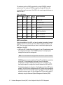
Table 1 shows the current list of the hardware models for HMCs supported in a
POWER4 or POWER5 environment. The HMCs are available as desktop or
rack-mountable systems.
2
Hardware Management Console (HMC) Case Configuration Study for LPAR Management
Table 1 Types of HMCs
Type
Supported managed
systems
HMC code version
7315-CR3 (rack mount)
POWER4 or POWER51
HMC 3.x, HMC 4.x, or
HMC 5.x
7315-C04 (desktop)
POWER4 or POWER51
HMC 3.x, HMC 4.x, or
HMC 5.x
7310-CR3 (rack mount)
POWER5
HMC 4.x or HMC 5.x
7310-C04 (desktop)
POWER5
HMC 4.x or HMC 5.x
1
- Licensed Internal Code needed (FC0961) to upgrade these HMCs to manager POWER5 systems. A single
HMC cannot be used to manage a mixed environment of POWER4 and POWER5 systems.
The HMC 3.x code version is used for POWER4 managed systems and HMC 4.x
for POWER5 systems (iSeries™ and pSeries®). For managing POWER5
pSeries machines, HMC 4.2 code version or later is required.
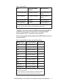
Table 2 shows a detailed relationship between the POWER5 pSeries servers and
the supported HMCs.
Table 2 Supported HMCs for pSeries and OpenPower platforms
Managed system
HMC model supported
HMC required
p505
7310-C04 or 7310-CR33
No1
p510
7310-C04 or 7310-CR33
No1
p520
7310-C04 or 7310-CR33
No1
p550
7310-C04 or 7310-CR33
No1
p570
7310-C04 or 7310-CR33
No1
p575
7310-C04 or 7310-CR33
Yes2
p590
7310-C04 or 7310-CR33
Yes2
p595
7310-C04 or 7310-CR33
Yes2
OpenPower™ 720
7310-C04 or 7310-CR33
No1
OpenPower 710
7310-C04 or 7310-CR33
No1
1
- An HMC is not required if the system runs in full system partition. For a partitioned
environment an HMC is required.
2 - It is recommended to have two HMCs installed for high availability considerations.
3 - Previous HMC models with the latest HMC code level are also supported.
Hardware Management Console (HMC) Case Configuration Study for LPAR Management
3
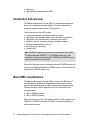
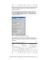
The maximum number of HMCs supported by a single POWER5 managed
system is two. The number of LPARs managed by a single HMC has been
increased from earlier versions of the HMC to the current supported release as
shown in Table 3.
Table 3 HMC history
HMC code
No. of
HMCs
No. of
servers
No. of
LPARs
Other information
4.1.x
1
4
40
iSeries Only
4.2.0
2
16
64
p5 520 550 570
4.2.1
2
32
160
OpenPower 720
4.3.1
2
32
254
p5 590 595
4.4.0
2
32
254
p5 575
HMC 7310-CR3/C04
4.5.0
2
32/48
254
48 for non 590/595
5.1.0
2
32/48
254
48 for non 590/595
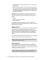
HMC connections
During the installation of the HMC, you have to consider the number of network
adapters required. You can have up to three Ethernet adapters installed on an
HMC. There are several connections you have to consider when planning the
installation of the HMC:
HMC to the FSP (Flexible Service Processor): It is an IP-based network used
for management functions of the POWER5 systems; for example, power
management and partition management.
Note: It is recommended to configure this connection as a private network.
POWER5 systems have two interfaces (T1 and T2) available for connections
to the HMC. It is recommended to use both of them for redundant
configuration, and high availability. Depending on your environment, you
have multiple options to configure the network between the HMC and FSP.
The default mechanism for allocation of the IP addresses for the FSP ports is
dynamic. The HMC can be configured as a DHCP server which allocates the
IP address at the time the managed system is powered on. Static IP address
allocation is also an option. You can configure the FSP ports with a static IP
address by using the Advanced System Management Interface (ASMI)
4
Hardware Management Console (HMC) Case Configuration Study for LPAR Management
menus. However not all POWER5 servers support this mechanism of
allocation. Currently p575, p590, and p595 servers support only DHCP.
Note: Either eth0 or eth1 can be a DHCP server on the HMC.
HMC to partitions: HMC requires TCP/IP connection to communicate with the
partitions for functions such as dynamic LPAR and Service Focal Point.
Service Agent (SA) connections: SA is the application running on the HMC for
reporting hardware failures to the IBM support center. It uses a modem for
dial-out connection or an available Internet connection. It can also be used to
transmit service and performance information to IBM and also for CoD
enablement and billing information.
Remote connection to the HMC using Web-based System Manager (WebSM)
or ssh: For accessing the graphical interface, you can use the WebSM
Remote Client running on UNIX® (AIX® or Linux®) or Windows®. The
command line interface is also available by using the secure shell connection
to the HMC. It can be used by an external management system or a partition
to perform HMC operations remotely.
When planning for the HMC installation also consider that the distance between
the HMC and the managed system must be within 8m (26 ft) distance. The
distance complies with IBM maintenance rules.
Partitioning considerations
With POWER5 systems a greater flexibility was introduced in setting up the
resources of a partition by enabling the Advanced Power Virtualization functions
to provide:
POWER™ Hypervisor: Supports partitioning and dynamic resource
movement across multiple operating system environments.
Shared processor LPAR (micro-partitioning): Enables you to allocate less
than a full physical processor to a logical partition.
Virtual LAN: Provides network Virtualization capabilities that allow you to
prioritize traffic on shared networks.
Virtual I/O (VIO): Provides the ability to dedicate I/O adapters and devices to
a virtual server, thus allowing the on demand allocation and management of
I/O devices.
Capacity on Demand (CoD): Allows system resources such as processors
and memory to be activated on an as-needed basis.
Simultaneous multi-threading (SMT): Allows applications to increase overall
resource utilization by virtualizing multiple physical CPUs through the use of
Hardware Management Console (HMC) Case Configuration Study for LPAR Management
5
multi-threading. SMT is a feature supported only in AIX 5.3 and Linux at an
appropriate level.
Multiple operating system support: Logical partitioning allows a single server
to run multiple operating system images concurrently. On a POWER5 system
the following operating systems can be installed: AIX 5L™ Version 5.2 ML4 or
later, SUSE Linux Enterprise Server 9 Service Pack 2, Red Hat Enterprise
Linux ES 4 QU1, and i5/OS.
Additional memory allocation in a partitioned environment
Three memory regions are reserved for the physical memory allocation of a
partition:
Hypervisor
Translation control entry (TCE) tables
Partition page tables
At the beginning of a partition size planning, you have to consider that the
allocated amount of memory in these three regions is not usable for the physical
memory allocation of the partition.
Hypervisor and TCE
All POWER5 systems require the use of the hypervisor. The hypervisor supports
many advanced functions including shared processors, Virtual I/O (VIO),
high-speed communications between partitions using Virtual LAN or concurrent
maintenance. There are many variables that dictate how much hypervisor
memory you will need. It is not a fixed amount of memory as with POWER4
systems.
Also the amount of IO drawers and the different ways to use IO, such as shared
environment, affect the amount of memory the hypervisor uses.
Note: The number of VIOs, the number of partitions, and the number of IO
drawers affect the hypervisor memory.
Partition page tables
Partition page tables are set aside in additional memory in the hypervisor to
handle the partition’s memory addressing. The amount of memory the partition
page table reserve depends on the maximum value of the partition, and must be
considered in your partition size planning.
Note: The bigger the maximum value of a partition, the bigger the amount of
memory not usable for the physical memory allocation of the partition.
6
Hardware Management Console (HMC) Case Configuration Study for LPAR Management
To calculate your desired and maximum memory values accurately, we
recommend that you use the LVT tool. This tool is available at:
http://www.ibm.com/servers/eserver/iseries/lpar/systemdesign.htm
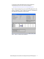
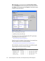
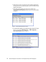
Figure 1 shows an example of how you can use the LPAR validation tool to verify
a memory configuration. In Figure 1, there are 4 partitions (P1..P4) defined on a
p595 system with a total amount of 32 GB of memory.
Figure 1 Using LVT to validate the LPAR configuration
Hardware Management Console (HMC) Case Configuration Study for LPAR Management
7
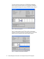
The memory allocated to the hypervisor is 1792 MB. When we change the
maximum memory parameter of partition P3 from 4096 MB to 32768 MB, the
memory allocated to the hypervisor increases to 2004 MB as shown in Figure 2.
Figure 2 Memory used by hypervisor
Figure 3 is another example of using LVT when verifying a wrong memory
configuration. Note that the total amount of allocated memory is 30 GB, but the
maximum limits for the partitions require a larger hypervisor memory.
Figure 3 An example of a wrong memory configuration
8
Hardware Management Console (HMC) Case Configuration Study for LPAR Management
Micro-partitioning
With POWER5 systems, increased flexibility is provided for allocating CPU
resources by using micropartitioning features. The following parameters can be
set up on the HMC:
Dedicated/shared mode, which allows a partition to allocate either a full CPU
or partial units. The minimum CPU allocation unit for a partition is 0.1.
Minimum, desired, and maximum limits for the number of CPUs allocated to a
dedicated partition.
Minimum, desired and maximum limits for processor units and virtual
processors, when using the shared processor pool.
Capped/uncapped and weight (shared processor mode).
Table 4 summarizes the CPU partitioning parameters with their range values,
and indicates if a parameter can be changed dynamically.
Table 4 Partition parameters
Parameter
Range
Dynamic
LPAR
Capped
Capped/uncapped
Yes
Weight
0-255
Yes
Processing mode
Dedicated/shared
Processor1
No
Processors (dedicated
CPUs)
Min-Max
Processing Units (shared
CPUs)
Min-Max Processing units1
Yes
Virtual processors
Min-Max virtual
processors2
Yes
Yes
1-
Max value is limited by the number of CPUs installed in the system,
including CoD.
2 - Between 1 and 64; the min and max allowed values are actually
determined by the min/max of processing units: at least 1 processor for
each 1.0 processing units and max value limited to 10*max processing
units or 64.
Min/Desired/Max values for CPU, processing units, and virtual processors can
be set only in the partition’s profile. Each time the partition is activated, it tries to
acquire the desired values. A partition cannot be activated if at least the
minimum values of the parameters cannot be satisfied.
Hardware Management Console (HMC) Case Configuration Study for LPAR Management
9
Note: Take into consideration that changes in the profile will not get activated
unless you power off and start up your partition. Rebooting of the operating
system is not sufficient.
Capacity on Demand
The Capacity on Demand (CoD) for POWER5 systems offers multiple options,
including:
Permanent Capacity on Demand:
– Provides system upgrades by activating processors and/or memory.
– No special contracts and no monitoring are required.
– Purchase agreement is fulfilled using activation keys.
On/Off Capacity on Demand:
– Enables the temporary use of a requested number of processors or
amount of memory.
– On a registered system, the customer selects the capacity and activates
the resource.
– Capacity can be turned ON and OFF by the customer; usage information
is reported to IBM.
– This option is post-pay. You are charged at activation.
Reserve Capacity on Demand:
– Used for processors only.
– Prepaid debit temporary agreement, activated using license keys.
– Adds reserve processor capacity to the shared processor pool, used if the
base shared pool capacity is exceeded.
– Requires AIX 5L Version 5.3 and the Advanced POWER Virtualization
feature.
Trial Capacity on Demand:
– Tests the effects of additional processors and memory.
– Partial or total activation of installed processors and/or memory.
– Resources are available for a fixed time, and must be returned after trial
period.
– No formal commitment required.
10
Hardware Management Console (HMC) Case Configuration Study for LPAR Management
HMC sample scenarios
The following examples illustrate POWER5 advance features.
Examples of using capped/uncapped, weight, dynamic LPAR and
CoD features
Our case study describes different possibilities to take advantage of the
micropartitioning features and CoD assuming a failover/fallback scenario based
on two independent servers. The scenario does not address a particular
clustering mechanism used between the two nodes. We describe the operation
by using both the WebSM GUI and the command line interface.
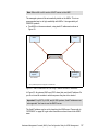
Figure 4 on page 12 shows the initial configuration. Node nils, a partion of a p550
system, is a production system with 2 CPUs and 7 GB memory. We will force
node nils to fail. Node julia, also a partion of a p550 system, is the standby
system for nils. The resources for julia are very small, just 0.2 processors and 1
GB memory.
In case of takeover, CoD On/Off will be activated. Two more CPUs and 8 GB
more memory will be available to add to a partion. You can use CoD On/Off for
our procedure because you have to pay for the actual days the CoD is active
only. You have to inform IBM about the amount of days you have made use of
CoD monthly. This can be done by the service agent automatically. For more
information, refer to “APPENDIX” on page 40.
Furthermore, the resources that will be available by activating CoD On/Off can
be assigned to dedicated and to shared partitions. After CoD activation, the CPU
and the memory resources will be assigned to julia so that julia will have the
same resources as nils had.
After nils is again up and running and ready to reacquire the application, julia will
reduce the resources as in the initial configuration and will deactivate CoD.
Hardware Management Console (HMC) Case Configuration Study for LPAR Management
11
P550 – 2 CPU - 8GB
P550 – 4 CPU – 8 GB
nils (production)
2 CPUs (dedicated)
7 GB
julia (standby)
0.2 CPU (shared)
1024 MB
Cluster
Oli (production)
1 CPU (dedicated)
5120 MB
Nicole_vio
0.8 CPU (shared)
1024 MB
HMC 1
HMC 2
Figure 4 Initial configuration
Table 5 shows our configuration in detail. Our test system has only one 4-pack
DASD available. Therefore we installed a VIO server to have sufficient disks
available for our partitions.
Table 5 CPU and memory allocation table
Partition
name
CPU
(Min/Desired/Max)
Virtual processors
(Min/Desired/Max)
Dedicated/
Shared
Capped/
Uncapped
nicole_vio
0.5/0.8/2.0
1/1/2
Shared
Capped
oli
1/1/4
N/A
Dedicated
N/A
julia
0.1/0.2/2.0
1/1/4
Shared
Capped
It is recommended to dedicate a processor when optimal performance is
required for the VIO server. However, in this section we use a shared processor
to configure our VIO to make the best use of the resources on our test system as
shown in Table 6 on page 13.
12
Hardware Management Console (HMC) Case Configuration Study for LPAR Management
Table 6 Memory allocation
Memory (MB)
Partition name
Min
Desired
Max
nicole_vio
512
1024
2048
oli
1024
5120
8192
julia
512
1024
8192
Enabling ssh access to HMC
By default, the ssh server on the HMC is not enabled. The following steps
configure ssh access for node julia on HMC. The procedure will allow node julia
to run HMC commands without providing a password.
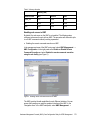
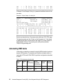
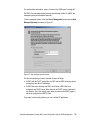
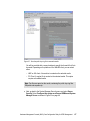
Enabling the remote command execution on HMC.
In the management area of the HMC main panel, select HMC Management →
HMC Configuration. In the right panel select Enable or Disable Remote
Command Execution and select Enable the remote command execution
using the ssh facility (see Figure 5).
Figure 5 Enabling remote command execution on HMC
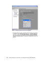
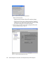
The HMC provides firewall capabilities for each Ethernet interface. You can
access the firewall menu using the graphical interface of the HMC. In the
“Navigation Area” of the HMC main panel, select HMC Management →
Hardware Management Console (HMC) Case Configuration Study for LPAR Management
13
HMC Configuration. In the right panel select Customize Network Setting,
press the LAN Adapters tab, choose the interface used for remote access and
press Details. In the new window select the Firewall tab. Check that the ssh port
is allowed for access (see Figure 6).
Figure 6 Firewall settings for eth1 interface
Install the ssh client on the AIX node:
The packages can be found on the AIX 5L Bonus Pack CD. To get the latest
release packages, access the following URL:
http://sourceforge.net/projects/openssh-aix
Openssl is required for installing the Openssh package. You can install it from
the AIX 5L Toolbox for Linux CD, or access the Web site:
http://www.ibm.com/servers/aix/products/aixos/linux/download.html
After the installation, verify that the openssh filesets are installed by using the
lslpp command on the AIX node, as shown in Example 1.
Example 1 Check openssh filesets are installed
root@julia/.ssh>lslpp -L |grep ssh
openssh.base.client
3.8.0.5302
openssh.base.server
3.8.0.5302
openssh.license
3.8.0.5302
openssh.man.en_US
3.8.0.5302
14
C
C
C
C
F
F
F
F
Open
Open
Open
Open
Secure
Secure
Secure
Secure
Shell Commands
Shell Server
Shell License
Shell
Hardware Management Console (HMC) Case Configuration Study for LPAR Management
openssh.msg.en_US
3.8.0.5302
C
F
Open Secure Shell Messages -
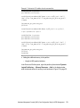
Log in the user account used for remote access to the HMC. Generate the
ssh keys using the ssh-keygen command. In Example 2, we used the root
user account and specified the RSA algorithm for encryption. The security
keys are saved in the /.ssh directory.
Example 2 ssh-keygen output
root@julia/>ssh-keygen -t rsa
Generating public/private rsa key pair.
Enter file in which to save the key (//.ssh/id_rsa):
Enter passphrase (empty for no passphrase):
Enter same passphrase again:
Your identification has been saved in //.ssh/id_rsa.
Your public key has been saved in //.ssh/id_rsa.pub.
The key fingerprint is:
72:fb:36:c7:35:4a:20:0d:57:7f:68:ce:d0:33:be:40 root@julia
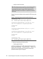
Distribute the public key in file id_rsa.pub to the HMC. In Example 3, we use
the mkauthkeys command to register the key for the hscroot account. The key
will be saved in the file authorized_keys2 on the $HOME/.ssh directory on the
HMC.
Example 3 Distribute the public key to the HMC
root@julia/>cd /.ssh
root@julia/.ssh>ls -l
total 16
-rw------1 root
system
887 Mar 30 19:52 id_rsa
-rw-r--r-1 root
system
220 Mar 30 19:52 id_rsa.pub
root@julia/.ssh>juliakey=`cat /.ssh/id_rsa.pub`
root@julia/.ssh>ssh hscroot@hmctot184 mkauthkeys -a \"$juliakey\"
The authenticity of host 'hmctot184 (10.1.1.187)' can't be established.
RSA key fingerprint is 00:2c:7b:ac:63:cd:7e:70:65:29:00:84:44:6f:d7:2e.
Are you sure you want to continue connecting (yes/no)?yes
Warning: Permanently added 'hmctot184,10.1.1.187' (RSA) to the list of known
hosts.
hscroot@hmctot184's password:
root@julia/.ssh>
root@julia/.ssh>
root@julia/.ssh>ssh hscroot@hmctot184 lshmc -V
"version= Version: 4
Release: 5.0
HMC Build level 20050519.1
MH00308: Required Maintenance Fix for V4R5.0 (04-25-2005)
"
root@julia/.ssh>
Hardware Management Console (HMC) Case Configuration Study for LPAR Management
15
Now, we force node nils to fail and prepare to start the takeover scenario (see
Figure 7).
P550 – 2 CPU - 8GB
P550 – 4 CPU – 8 GB
1
nils (production)
2 CPUs (dedicated)
7 GB
julia (production)
2 CPU (shared)
7 GB
takeover
oli (production)
1 CPU (dedicated)
5120 MB
nicole_vio (VIO server)
0.8 CPU (shared)
1024 MB
CoD activation
DLPAR operations
HMC 1
2
HMC 2
1 - Failover to node julia
2 - Node julia remotely activates CoD and performs DLPAR operations via HMC
Figure 7 CoD and dynamic LPAR operations after takeover
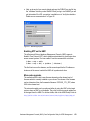
Enabling On/Off CoD for processor and memory
Before activating the CPU and memory resources, you have to prepare the CoD
environment by getting an enablement code from IBM. For more information
about how to get an activation code, refer to the CoD Web site:
http://www.ibm.com/servers/eserver/pseries/ondemand/cod/
Activating On/Off CoD using the graphical interface. From the Server
Management window, highlight the managed system. Click on Selected →
Manage on Demand Activations → Capacity on Demand (see Figure 8 on
page 17).
16
Hardware Management Console (HMC) Case Configuration Study for LPAR Management
Figure 8 Activating the On/Off CoD
Activating On/Off CoD using the command line interface.
Example 4 shows how node julia activates 2 CPUs and 8 GB of RAM for 3 days
by running via ssh the command chcod on the HMC.
Example 4 Activating CoD using command line interface
CPU:
root@julia/.ssh>ssh hscroot@hmctot184 "chcod
-r proc -q 2 -d 3"
-m
p550_itso1
-o a
-c onoff
Memory:
root@julia/.ssh>ssh hscroot@hmctot184 "chcod -m p550_itso1 -o a -c onoff -r
mem -q 8192 -d 3"
Perform the dynamic LPAR operations to increase the CPU units and
memory capacity of the target partition.
After enabling the CoD feature for CPU, the additional processors are
automatically added in the shared processor pool and can be assigned to any
shared or dedicated partition.
Hardware Management Console (HMC) Case Configuration Study for LPAR Management
17
Note: If you use reserve CoD instead of ON/OFF CoD to temporarily activate
processors, you can assign the CPUs to shared partitions only.
In order for node julia to operate with the same resources as node nils had, we
have to add 1.8 processing units and 6.5 GB memory to this node.
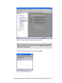
Allocation of processor units.
– Using the graphical user interface.
In the Server and Partition panel on HMC, right-click on partition julia and select
Dynamic Logical Partitioning → Processor Resources → Add. In the dialog
window, enter the desired values for additional processing units and virtual
processors as shown in Figure 9.
Figure 9 Performing dynamic LPAR operation for CPU
– Using the command line interface.
In Example 5, we run the command lshwres on the HMC to get the current
values of the cpu units and virtual processors used by node julia, before and after
increasing the processing units.
18
Hardware Management Console (HMC) Case Configuration Study for LPAR Management
Example 5 Perform the CPU addition from the command line
root@julia/>lsdev -Cc processor
proc0 Available 00-00 Processor
root@julia/>ssh hscroot@hmctot184 lshwres -r proc -m p550_itso1 --level\ \
>lpar --filter "lpar_names=julia" -F lpar_name:curr_proc_units:curr_procs\ \
>--header
lpar_name:curr_proc_units:curr_procs
julia:0.2:1
root@julia/>ssh hscroot@hmctot184 chhwres -m p550_itso1 -o a -p julia \ \
-r proc --procunits 1.8 --procs 1
root@julia/>lsdev -Cc processor
proc0 Available 00-00 Processor
proc2 Available 00-02 Processor
root@julia/>ssh hscroot@hmctot184 lshwres -r proc -m p550_itso1 --level \ \
>lpar --filter "lpar_names=julia" -F lpar_name:curr_proc_units:curr_procs\ \
>--header
lpar_name:curr_proc_units:curr_procs
julia:2.0:2
root@julia/>
Adding the additional memory to the partition:
– Using the HMC graphical interface.
In the Server and Partition panel, right-click partition julia and select Dynamic
Logical Partitioning → Memory Resources → Add. In the dialog window,
enter the desired amount of memory to add as shown in Figure 10 on page 20.
Hardware Management Console (HMC) Case Configuration Study for LPAR Management
19
Figure 10 Add memory to partition
– Using the command line.
Example 6 shows how to allocate 6 GB of memory to partition julia.
Example 6 Memory allocation using command line interface
root@julia/>lsattr -El mem0
goodsize 1024 Amount of usable physical memory in Mbytes False
size
1024 Total amount of physical memory in Mbytes False
root@julia/>ssh hscroot@hmctot184 lshwres -r mem -m p550_itso1 --level \ \
>lpar --filter "lpar_names=julia" -F lpar_name:curr_mem --header
lpar_name:curr_mem
julia:1024
root@julia/>ssh hscroot@hmctot184 chhwres -m p550_itso1 -o a -p julia \ \
>-r mem -q 6144 -w 15
root@julia/>lsattr -El mem0
goodsize 7168 Amount of usable physical memory in Mbytes False
size
7168 Total amount of physical memory in Mbytes False
root@julia/>ssh hscroot@hmctot184 lshwres -r mem -m p550_itso1 --level \ \
>lpar --filter "lpar_names=julia" -F lpar_name:curr_mem --header
lpar_name:curr_mem
julia:7168
20
Hardware Management Console (HMC) Case Configuration Study for LPAR Management
At the time node nils is back and ready to reacquire the applications running on
node julia, we reduce the memory and CPU to the initial values and turn off CoD.
In order for node julia to operate with the initial resources, we have to remove 1.8
processing units and 6 GB memory from this partition.
1. Perform dynamic LPAR operations to decrease the CPU units and memory
capacity of the target partition.
The following steps are taken to decrease the CPU units and memory capacity of
the target partition.
Perform the dynamic LPAR operation for CPU.
– Using the graphical interface on the HMC.
In the Server and Partition panel, right-click partition julia and select Dynamic
Logical Partitioning → Memory Resources → Add. In the dialog window,
enter the desired amount of memory to remove as shown in Figure 11.
Figure 11 Removing memory from partition
Hardware Management Console (HMC) Case Configuration Study for LPAR Management
21
– Using the command line interface.
Note: When allocating memory to a partition or moving it between partitions,
you can increase the time-out limit of the operation to prevent a failure
response before the operation completes. Use the Advance tab of the
dynamic LPAR memory menu (see Figure 10 on page 20) to increase the
time-out limit.
Example 7 shows how to deallocate via the command line 6 GB of memory from
node julia.
Example 7 Deallocating the memory using the command line interface (CLI)
root@julia/>lsattr -El mem0
goodsize 7168 Amount of usable physical memory in Mbytes False
size
7168 Total amount of physical memory in Mbytes False
root@julia/>ssh hscroot@hmctot184 lshwres -r mem -m p550_itso1 --level\ \
>lpar --filter "lpar_names=julia" -F lpar_name:curr_mem --header
lpar_name:curr_mem
julia:7168
root@julia/>ssh hscroot@hmctot184 chhwres -m p550_itso1 -o r -p julia \ \
> -r mem -q 6144 -w 15
root@julia/>ssh hscroot@hmctot184 lshwres -r mem -m p550_itso1 --level\ \
>lpar --filter "lpar_names=julia" -F lpar_name:curr_mem --header
lpar_name:curr_mem
julia:1024
root@julia/>lsattr -El mem0
goodsize 1024 Amount of usable physical memory in Mbytes False
size
1024 Total amount of physical memory in Mbytes False
Deallocate the processing units from the partition.
– Using the graphical interface.
In the Server and Partition panel on HMC, right-click partition julia and select
Dynamic Logical Partitioning → Processor Resources → Remove. In the
dialog window, enter the desired values for processing units and virtual
processors as shown in Figure 12 on page 23.
22
Hardware Management Console (HMC) Case Configuration Study for LPAR Management
Figure 12 Perform the deallocation for the CPU units
– Using the command line interface to remove 1.8 processing units from
node julia is shown in Example 8.
Example 8 Deallocating the CPU
root@julia/>lsdev -Cc processor
proc0 Available 00-00 Processor
proc2 Available 00-02 Processor
root@julia/>ssh hscroot@hmctot184 lshwres -r proc -m p550_itso1 --level\ \
>lpar --filter "lpar_names=julia" -F lpar_name:curr_proc_units:curr_procs\ \
>--header
lpar_name:curr_proc_units:curr_procs
julia:2.0:2
root@julia/>ssh hscroot@hmctot184 chhwres -m p550_itso1 -o r -p julia \ \
>-r proc --procunits 1.8 --procs 1
root@julia/>ssh hscroot@hmctot184 lshwres -r proc -m p550_itso1 --level\ \
>lpar --filter "lpar_names=julia" -F lpar_name:curr_proc_units:curr_procs\ \
>--header
lpar_name:curr_proc_units:curr_procs
julia:0.2:1
root@julia/>lsdev -Cc processor
proc2 Available 00-02 Processor
Hardware Management Console (HMC) Case Configuration Study for LPAR Management
23
2. Deactivating the On/Off CoD for CPU and memory.
For an example of the graphical interface, refer to the menu presented in Figure 8
on page 17, and the section “Activating On/Off CoD using the command line
interface.” on page 17.
Example 9 shows how to use the command line interface to deactivate the
processor and memory CoD resources.
Example 9 Disabling all allocated CoD resources for CPU and memory
Memory:
ssh hscroot@hmctot184 chcod
CPU:
ssh hscroot@hmctot184
chcod
-m
p550_itso1 -o d -c onoff -r mem
-m p550_itso1
-o d
-c onoff -r proc
Considerations for capped/uncapped partitions
There is an alternate way to set up a partition to acquire processing units by
allowing it to dynamically use the idle CPU units from the shared processor pool,
even if the processor units are entitled to a shared processor partition or not used
in a partition. The units belonging to the dedicated processors can be still used
by an uncapped partition if the flag “Allow idle processors to be shared” is set,
and the dedicated partition is shutdown.
In case there are more than one uncapped partitions, you can use the weight
parameter to determine the priority. This value is used proportionally. The higher
the weight, the higher the priority to acquire the processing units.
Example of using a single uncapped partition
In the above scenario, we changed the properties of partition julia from capped to
uncapped mode, so it can exceed the 0.2 entitled processor units. In this case,
there is no need to perform a CPU dynamic LPAR operation. The operation can
be performed dynamically.
To access the menus, from the Server Management menu of the HMC,
right-click on the partition name and select Dynamic Logical Partitioning →
Processor Resources →Add. Refer to Figure 13 on page 25.
24
Hardware Management Console (HMC) Case Configuration Study for LPAR Management
Figure 13 Toggle the Capped/Uncapped option
You have to consider the number of virtual processors to be able to use all the
CPUs from the shared processor pool.
In our example, after the CoD operation, we have 3.0 available processing units
in the shared processor pool and 1 dedicated processor allocated to node oli.
The partition nicole_vio uses 0.8 processing units and is capped.
Partition julia uses 0.2 units and 1 virtual processor, and can use 1 physical CPU.
Adding 1 virtual CPU allows this partition to use a maximum of 2.0 processing
units.
In Example 10, we produced heavy CPU load on partition julia while the other
partition using the shared processor pool is in an idle state. The physc parameter
shows the actual number of physical processing units used by partition julia.
Example 10 Output of topas -L
Interval:
2
Logical Partition: julia
Tue Mar 31 16:20:46 1970
Psize:
3
Shared SMT OFF
Online Memory:
512.0
Ent: 0.20
Mode: UnCapped
Online Logical CPUs: 2
Partition CPU Utilization
Online Virtual CPUs: 2
%usr %sys %wait %idle physc %entc %lbusy app
vcsw phint %hypv
hcalls
100
0
0
0 2.0 999.70100.00 1.00
200
0
0.0
0
===============================================================================
LCPU minpf majpf intr csw icsw runq lpa scalls usr sys _wt idl
pc lcsw
Cpu0
0
0
527 258 234
4 100
65 100
0
0 0 1.00
83
Cpu1
0
0
211 246 209
2 100
520 100
0
0 0 1.00
117
Hardware Management Console (HMC) Case Configuration Study for LPAR Management
25
Example of using two uncapped partitions and the weight
For the example of two uncapped partitions using the same shared processor
pool, we use the configuration described in Table 7.
Table 7 CPU allocation table
Partition
name
CPU
(Min/Des/Max)
Virtual
processors
(Min/Des/Max)
Dedicated/
Shared
Capped/
Uncapped
Weight
nicole_vio
1/1/1
N/A
Dedicated
N/A
N/A
oli
0.1/1.0/2.0
1/4/4
Shared
Uncapped
128
julia
0.1/1.0/2.0
1/4/4
Shared
Uncapped
128
We created a heavy CPU load on both uncapped partitions and verified their load
using the topas -L command.
Example 11 Output of topas -L from node oli
Interval:
7
Logical Partition: oli
Tue Mar 31 17:37:56 1970
Psize:
3
Shared SMT OFF
Online Memory:
5632.0
Ent: 1.00
Mode: UnCapped
Online Logical CPUs: 4
Partition CPU Utilization
Online Virtual CPUs: 4
%usr %sys %wait %idle physc %entc %lbusy app
vcsw phint %hypv
hcalls
100
0
0
0 1.5 148.75100.00 0.00
8526
0
0.0
0
===============================================================================
LCPU minpf majpf intr csw icsw runq lpa scalls usr sys _wt idl
pc lcsw
Cpu0
0
0 1536 795 733
6 100
33 100
0
0 0 0.37 2160
Cpu1
0
0
715 718 706
6 100
22 100
0
0 0 0.37 2139
Cpu2
0
0
751 738 700
6 100
6 100
0
0 0 0.37 2091
Cpu3
0
0
704 730 701
5 100
51 100
0
0 0 0.37 2136
Example 11 and Example 12 are the outputs of the topas -L command from
nodes oli and julia, including the same weight value.
Example 12 Output of topas -L from node julia
Interval:
7
Logical Partition: julia
Tue Mar 31 17:38:31 1970
Psize:
3
Shared SMT OFF
Online Memory:
512.0
Ent: 1.00
Mode: UnCapped
Online Logical CPUs: 4
Partition CPU Utilization
Online Virtual CPUs: 4
%usr %sys %wait %idle physc %entc %lbusy app
vcsw phint %hypv
hcalls
100
0
0
0 1.5 149.45100.00 0.00
8692
1
0.0
0
===============================================================================
LCPU minpf majpf intr csw icsw runq lpa scalls usr sys _wt idl
pc lcsw
Cpu0
0
0
738 869 771
7 100
209 100
0
0 0 0.37 2184
Cpu1
0
0 1547 852 789
5 100 16995 99
1
0 0 0.37 2158
26
Hardware Management Console (HMC) Case Configuration Study for LPAR Management
Cpu2
Cpu3
0
0
0
0
757
712
771
712
699
698
6 100
6 100
15 100
27 100
0
0
0
0
0 0.37
0 0.37
2172
2178
We changed the weight for the partition oli to the maximum value 255 while
partition julia is set to 128.
The operation can be performed dynamically. For accessing the GUI menus,
from the Server Management menu of the HMC, right-click on the partition
name and select Dynamic Logical Partitioning → Processor Resources
→Add (as shown in Figure 14).
Figure 14 Dynamically changing the weight of the partition
When both partitions are heavy CPU loaded, the amount of processing units
allocated from the processor shared pool is proportional to the weight value of
the partitions.
Example 13 Output of topas -L on node oli
Interval:
7
Logical Partition: oli
Tue Mar 31 17:49:50 1970
Psize:
3
Shared SMT OFF
Online Memory:
5632.0
Ent: 1.00
Mode: UnCapped
Online Logical CPUs: 4
Partition CPU Utilization
Online Virtual CPUs: 4
vcsw phint %hypv
hcalls
%usr %sys %wait %idle physc %entc %lbusy app
100
0
0
0 1.7 165.87100.00 0.00 10644
0 0.0
0
===============================================================================
LCPU minpf majpf intr csw icsw runq lpa scalls usr sys _wt idl
pc lcsw
Cpu0
0
0 1628 862 767
8 100
81 100
0
0 0 0.41 2652
Cpu1
0
0
717 720 708
8 100
14 100
0
0 0 0.42 2657
Hardware Management Console (HMC) Case Configuration Study for LPAR Management
27
Cpu2
Cpu3
0
0
0
0
756
702
740
703
700
699
8 100
8 100
19 100
2 100
0
0
0
0
0 0.42
0 0.41
2683
2652
In Example 13 and Example 14 the physc parameter has different values for the
two nodes.
Example 14 Output of topas -L on node julia
Interval:
7
Logical Partition: julia
Tue Mar 31 17:49:57 1970
Psize:
3
Shared SMT OFF
Online Memory:
512.0
Ent: 1.00
Mode: UnCapped
Online Logical CPUs: 4
Partition CPU Utilization
Online Virtual CPUs: 4
%usr %sys %wait %idle physc %entc %lbusy app
vcsw phint %hypv
hcalls
100
0
0
0 1.3 132.73100.00 0.00
6701
6
0.0
0
===============================================================================
LCPU minpf majpf intr csw icsw runq lpa scalls usr sys _wt idl
pc lcsw
Cpu0
0
0
731 813 726
7 100
31 100
0
0 0 0.33 1683
Cpu1
0
0 1490 791 729
8 100
29 100
0
0 0 0.33 1634
Cpu2
0
0
765 765 704
8 100
18 100
0
0 0 0.33 1697
Cpu3
0
0
713 711 696
9 100
307 100
0
0 0 0.33 1687
Node oli and node julia have 1.0 processor units entitled and 100% CPU usage.
The shared processor pool has 3.0 units, so the idle capacity is 1.0 unit shared
by partitions julia and oli, proportionally to their weight. In our case, partition oli
adds 255/(255+128) from 1.0 processing units, while partition julia adds
128/(255+128) processing units.
Automating HMC tasks
In this section, we describe an example of using the HMC scheduler to perform a
dynamic LPAR operation. The example uses 2 partitions in shared mode on a
system with 4 CPUs and 8 GB of RAM. Our partitions’ configuration is described
in Table 8.
Table 8 CPU and memory allocation table
28
Partition
name
Memory
(GB)
CPU
(Min/Des/Max)
Virtual
processors
(Min/Des/Max)
Dedicate/
Shared
Capped/
Uncapped
oli
1/5/8
0.1/3.0/4.0
1/4/4
Shared
Uncapped
julia
1/2/8
0.1/1.0/4.0
1/4/4
Shared
Uncapped
Hardware Management Console (HMC) Case Configuration Study for LPAR Management
Node oli has increased processing loads during the workday: 7 AM to 7 PM and
it is idle most of the time outside this interval. Partition julia has an increased
processing load during 10 PM to 5 AM and is idle the rest of the time. Since both
partitions are uncapped, we will reallocate only a piece of memory to partition
julia during the idle period of time of partition oli.
This example shows how to implement via the HMC scheduler the dynamic
LPAR operations for the memory. We implement two scheduled operations that
run every day:
9 PM: Move 2 GB of memory from partition oli to partition julia.
6 AM: Move 2 GB of memory back from partition julia to partition oli.
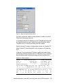
The following steps are performed from the HMC to configure the scheduled
dynamic LPAR operations:
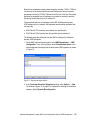
1. On the HMC main configuration panel, select HMC Management → HMC
Configuration. Then, in the right panel select Schedule operations. In the
new window select the target node for the dynamic LPAR operation as shown
in Figure 15.
Figure 15 Selecting the target partition
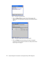
2. In the Customize Scheduled Operations window, select Options → New.
The window in Figure 16 on page 30 is displayed for selecting the scheduled
operation. Select Dynamic Reconfiguration.
Hardware Management Console (HMC) Case Configuration Study for LPAR Management
29
Figure 16 Selecting the scheduled operation
3. Next, in the Date and Time tab, select the time for the beginning of the
operation and a time window where the operation can be started as shown in
Figure 17.
Figure 17 Selecting the starting window of the scheduled operation
4. Click on the Repeat tab and select the days of the week for running the
scheduler. We selected each day of the week for an infinite period of time as
shown in Figure 18 on page 31.
30
Hardware Management Console (HMC) Case Configuration Study for LPAR Management
Figure 18 Selecting the days of the week for the schedule
5. Click on the Options tab and specify the details of the dynamic LPAR
operation as shown in Figure 19.
Figure 19 Specifying the details of the dynamic LPAR operation
Click on the Save button to activate the scheduler.
Note: By default, the time-out period for the dynamic LPAR operation is 5
minutes. In our test case, the memory reallocation was performed for 2GB of
RAM. When performing this operation, higher values might require a larger
time to complete.
Hardware Management Console (HMC) Case Configuration Study for LPAR Management
31
6. Repeat steps 1 through 5 for creating the reverse operation, specifying julia
the target partition for the scheduled operation, and 06:00:00 AM for the start
window of the scheduler.
7. After setting up both operations, their status can be checked in the
Customize Scheduled Operations window for each of the nodes as shown
in Figure 20.
Figure 20 Current scheduled operations for node oli
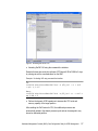
8. For checking the completion of the scheduled operation, display the Console
Events Log, by selecting HMC Management → HMC Configuration →
View Console Events as shown in Figure 21.
Figure 21 Verifying the completion of the scheduled operation
32
Hardware Management Console (HMC) Case Configuration Study for LPAR Management
Comparing profile values with current settings
If you perform a dynamic LPAR operation and you want to make this change
permanent, you have to do maintenance on the appropriate profile. Otherwise,
after the next shutdown and power on of the LPAR, the partition will have the old
properties and this might not be desired.
The script in Example 15 compares minimum, desired, and maximum values
regarding CPU and memory of a the profiles with the current settings. You can
use it to monitor these settings.
In Example 15, hmc1 and hmc2 are monitored. To use this script, you have to
change hmc1 and hmc2 with the names of your HMCs. The amount of HMCs is
variable as long as they are in quotation marks and comma separated.
Place this script on a partition that has ssh access with a special user to every
HMCs you want to monitor. In the example, we used the user hscroot. It is
necessary that you can get access without the need to type in the password. To
do so, please refer to “Enabling ssh access to HMC” on page 13.
Example 15 Monitoring sample script
#!/usr/bin/perl
$fmem = "curr_min_mem,curr_mem,curr_max_mem,lpar_name"; # define output fields
$fproc = "curr_min_procs,curr_procs,curr_max_procs,lpar_name";
$flds =
"min_mem,desired_mem,max_mem,min_procs,desired_procs,max_procs,min_mem,lpar_nam
e";
for $hmc ("hmc1", "hmc2") {
# for all my HMC to check
$syscfg = "ssh hscroot\@$hmc lssyscfg -r ";
# command to get
HMC-Sys-Info
@ceclist = split(/\n/, `$syscfg sys -F name`);
# get names of CECs
for $cec (@ceclist) {
# for every cec in list
$hwres = "ssh hscroot\@$hmc lshwres -m $cec -r ";# cmd to get current value
@lparlist = split(/\n/, `$syscfg lpar -m $cec -F name`);# read lpars for
curr cec
for $lpar (@lparlist) {
# read the values for lpar
($p->{min_mem}, $p->{des_mem}, $p->{max_mem},
$p->{min_procs}, $p->{des_procs}, $p->{max_procs}) = split(/,/,
`$syscfg prof -m $cec --filter lpar_names=$lpar -F $flds`);
($a->{min_mem}, $a->{des_mem}, $a->{max_mem}) = split(/,/,
`$hwres mem --level lpar --filter lpar_names=$lpar -F $fmem`);
($a->{min_procs}, $a->{des_procs}, $a->{max_procs}) = split(/,/,
`$hwres proc --level lpar --filter lpar_names=$lpar -F $fproc`);
for $field (keys %$p) {
# output data and any
difference
printf("\n%8s %8s %12s %12s: prof=%8d ", $hmc, $cec, $lpar, $field,
$p->{$field});
printf("curr=%8d", $a->{$field}) unless ($p->{$field} == $a->{$field});
Hardware Management Console (HMC) Case Configuration Study for LPAR Management
33
};
};
};
};
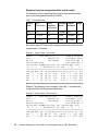
Here is a sample output from the script shown in Example 15 on page 33.
Example 16 Monitoring sample script output
julia:/home/romeo # ./compare_profile_current
hmc1
hmc1
hmc1
hmc1
hmc1
hmc1
hmc1
hmc1
hmc1
hmc1
hmc1
hmc1
hmc1
hmc1
hmc1
hmc1
hmc1
hmc1
hmc1
hmc1
hmc1
hmc1
hmc1
hmc1
hmc1
hmc1
hmc1
hmc1
hmc1
hmc1
hmc2
hmc2
hmc2
hmc2
hmc2
hmc2
hmc2
hmc2
34
cec-blue
cec-blue
cec-blue
cec-blue
cec-blue
cec-blue
cec-blue
cec-blue
cec-blue
cec-blue
cec-blue
cec-blue
cec-blue
cec-blue
cec-blue
cec-blue
cec-blue
cec-blue
cec-blue
cec-blue
cec-blue
cec-blue
cec-blue
cec-blue
cec-blue
cec-blue
cec-blue
cec-blue
cec-blue
cec-blue
cec-green
cec-green
cec-green
cec-green
cec-green
cec-green
cec-green
cec-green
blue5
blue5
blue5
blue5
blue5
blue5
blue7
blue7
blue7
blue7
blue7
blue7
blue6
blue6
blue6
blue6
blue6
blue6
blue4
blue4
blue4
blue4
blue4
blue4
blue3
blue3
blue3
blue3
blue3
blue3
vio2
vio2
vio2
vio2
vio2
vio2
green2
green2
min_mem:
des_mem:
max_mem:
max_procs:
min_procs:
des_procs:
min_mem:
des_mem:
max_mem:
max_procs:
min_procs:
des_procs:
min_mem:
des_mem:
max_mem:
max_procs:
min_procs:
des_procs:
min_mem:
des_mem:
max_mem:
max_procs:
min_procs:
des_procs:
min_mem:
des_mem:
max_mem:
max_procs:
min_procs:
des_procs:
min_mem:
des_mem:
max_mem:
max_procs:
min_procs:
des_procs:
min_mem:
des_mem:
prof=
prof=
prof=
prof=
prof=
prof=
prof=
prof=
prof=
prof=
prof=
prof=
prof=
prof=
prof=
prof=
prof=
prof=
prof=
prof=
prof=
prof=
prof=
prof=
prof=
prof=
prof=
prof=
prof=
prof=
prof=
prof=
prof=
prof=
prof=
prof=
prof=
prof=
1024
4096
16384
8
1
1
1024
2048
16384
8
1
1
1024
4096
16384
8
1
1
1024
2048
16384
8
1
2
1024
16384
31744
8
1
4
1024
4096
8192
20
1
2
2048
12288
curr=
2048
curr=
1
curr=
20480
curr=
curr=
curr=
curr=
curr=
curr=
0
0
0
0
0
0
curr=
10240
Hardware Management Console (HMC) Case Configuration Study for LPAR Management
hmc2
hmc2
hmc2
hmc2
hmc2
hmc2
hmc2
hmc2
hmc2
hmc2
cec-green
cec-green
cec-green
cec-green
cec-green
cec-green
cec-green
cec-green
cec-green
cec-green
green2
green2
green2
green2
green3
green3
green3
green3
green3
green3
max_mem:
max_procs:
min_procs:
des_procs:
min_mem:
des_mem:
max_mem:
max_procs:
min_procs:
des_procs:
prof=
prof=
prof=
prof=
prof=
prof=
prof=
prof=
prof=
prof=
32768
4
1
2
2048
12288 curr=
32768
4
1
2 curr=
4608
1
In Example 16 on page 34, you can see that the LPAR blue6 has 2 GB memory
configured instead of the desired 4 GB or that LPAR blue4 works currently with
one processor instead of the desired 2 processors. LPAR vio2 is down, therefore
the current values are all set to 0.
High availability considerations for HMCs
The following sections describe high availability consideration for HMCs.
Working with redundant HMCs
The HMC is mandatory for all POWER5 systems working in a partitioned
environment, and therefore the HMC is a very important hardware component.
For some environments, it might be useful to work with redundant HMCs.
There is no special installation procedure or configuration needed to work with
two HMCs. They are installed in the usual manner. Both are active and ready to
take management tasks at any time.
The HMCs are automatically notified of any changes that occur in the managed
system. If there is a change on one HMC, a couple of seconds later, it is visible
on the second one automatically. Or if the managed system sends a state or an
operator panel value, for example, when a LPAR is starting, the different states
and LED codes will be visible on both HMCs at the same time.
There is a locking mechanism to prevent basic conflicts. For the amount of time it
takes to handle an operation, the HMC gets exclusive control over the interface
of the managed system. After this operation is completed, the lock will be
released and the interface is released for further commands.
Important: When using a service agent, enable it on one HMC only to prevent
duplicated service calls.
Hardware Management Console (HMC) Case Configuration Study for LPAR Management
35
Working with two HMCs eases the planning of HMC downtimes for software
maintenance, as there is no downtime needed. While doing the HMC code
update on one HMC, the other one continues to manage the environment. This
situation allows one HMC to run at the new fix level, while the other HMC can
continue to run the previous one. You should take care to move both HMCs to
the same level to provide an identical user interface.
High availability HMCs in various network environments
Using DHCP-servers or working with a fixed IP-address for the CEC are
considerations going along with your network structure. Here are some examples
of how you can set up your network:
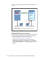
Two HMCs on different private networks are shown in Figure 22.
DHCP Server
DHCP Server
HMC1
HMC2
eth0
T1
eth0
T2
P5 Managed
System
T1
T2
P5 Managed
System
Figure 22 HMCs connected to the SFP using 2 networks
Figure 22 describes two HMCs in different networks both running DHCP servers.
The CEC uses two LAN-adapters, one gets the IP-address from HMC1 and the
second one from HMC2.
If you use your HMC as a DHCP server for the CEC, be sure to have the HMC up
and running before powering on the CEC; otherwise the CEC will get its default
IP-address and will not work in your network.
36
Hardware Management Console (HMC) Case Configuration Study for LPAR Management
Note: Either eth0 or eth1 can be a DHCP server on the HMC.
The managed system will be automatically visible on the HMCs. This is our
recommended way to do high availability with HMCs. It is supported by all
POWER5 systems.
Two HMCs on the same network, using static IP addresses is shown in
Figure 23.
HMC1
HMC2
T1
T1
P5 Managed
System*
P5 Managed
System*
Fix IP-Address
Fix IP-Address
* p575, p590 and p595 do not support fix IP addresses
Figure 23 HMCs connected to the FSP using 1 network and static IP addresses
In Figure 23, all systems HMCs and CECs have their own fixed IP-address. So
you do not need to consider in which sequence they has to be started.
Important: For p5-575, p5-590, and p5-595 systems, fixed IP-addresses are
not supported. You have to use the DHCP server.
The fixed IP-address can be set by launching the ASMI menu. Please refer to
“APPENDIX” on page 40 to get more information on how to launch the ASMI
menu.
Hardware Management Console (HMC) Case Configuration Study for LPAR Management
37
A new system is shipped with a default IP-addresses. You can change these
IP-addresses by connecting your laptop to either T1 or T2 of the CEC. Assign an
IP-address to your laptop’s interface that is in the same network as the
respective network adapter of your CEC. For T1, it is network 192.168.2.0/24
and for T2 192.168.3.0/24. Do not use the same IP-addresses as the CEC
already have assigned.
Note: For p510, p520, p550, and p570 at first startup, a default IP address is
configured on the FSP interfaces if an DHCP server is not available:
eth0 (external T1): 192.168.2.147
eth1 (external T2): 192.168.3.147
Run a browser on your laptop and type in the IP-address of the respective
network adapter of the CEC:
https://192.168.2.147
Log in to the ASMI menu using a username and a password. In the main ASMI
panel, select Network Services → Network Configuration. Using the menu
from Figure 24, you can configure the FSP Ethernet interfaces eth0 and eth1.
Figure 24 Configuring the FSP IP address using the ASMI menu
38
Hardware Management Console (HMC) Case Configuration Study for LPAR Management
For more detailed information, refer to “Access to the ASMI menu” on page 40“.
On HMC1, the managed system becomes automatically visible. On HMC2, the
managed system must be added manually.
To add a managed system, select the Server Management bar and choose Add
Managed System(s) as shown in Figure 25.
Figure 25 Add managed systems window
For this configuration you have to consider a couple of things:
If HMC1 with the DHCP server fails, the CEC and the HMC will work properly
as long they have their IP-addresses.
If HMC2 has to be rebooted and HMC1 is still down, HMC2 has to be
configured as a DHCP server. Note that only one DHCP server is allowed in
one network. So in this unlikely case, when you want to start HMC1 again, it
has to be configured as a DHCP client.
If you want to avoid such problems, you can use fixed IP-addresses.
Hardware Management Console (HMC) Case Configuration Study for LPAR Management
39
APPENDIX
The following sections contain additional information to be considered when
dealing with HMCs.
Access to the ASMI menu
Depending on your network connection to the FSP interfaces, you have several
possibilities to access the ASMI menu using an IP connection:
Using a Web browser:
Connect a system to the FSP network, launch a browser, and access the
following URL:
https://<FSP_IP_address>
This method is useful especially if you do not have an HMC attached to the
POWER5 system or for configuring static IP addresses at the installation
time. For example, you can use a laptop directly connected to the FSP port.
From the HMC:
Assuming the HMC-to-FSP connection is properly set up and the managed
system is accessible by the HMC, use the HMC graphical interface to launch
the ASMI menu panel.
In the HMC main panel, select Service Application → Service Focal Point.
Click Service Utilities and highlight the managed system. In the Selected
pull down menu, click on Launch ASM Menu.
Using WebSM:
This feature requires HMC Code Version 4.5 or later. To access the ASMI
menu using WebSM, follow the same steps as accessing the ASMI menu
from the HMC. You get a similar panel as shown in Figure 26 on page 41.
40
Hardware Management Console (HMC) Case Configuration Study for LPAR Management
Figure 26 Accessing the ASMI menu using WebSM
For further information related to the access to the ASMI menus, refer to the
“ASMI Setup Guide” at:
http://publib.boulder.ibm.com/infocenter/eserver/v1r2s/en_US/info/iphby/iphby.pdf
Configuring a secure connection for WebSM
The following example describes how to set up a secure WebSM connection for
a Windows client and a cluster of two HMCs.
Note: Before configuring the WebSM client, ensure that your name resolution
works properly. The HMC hostname must be resolved by the PC client station.
If a DNS is not configured, then put the HMC hostname in the hosts file. For
Windows XP, the file is C:\Windows\system32\drivers\etc\hosts.
Download the WebSM client code from the HMC. Open a browser and
access the following URLs:
http://<hmchost>/remote_client.html
Log in the HMC using the hscroot account. Run the InstallShield for your
platform.
Hardware Management Console (HMC) Case Configuration Study for LPAR Management
41
Access the secure WebSM download page and run the InstallShield program
for your platform:
http://<hmchost>/remote_client_security.html
Verify the WebSM installation by starting the WebSM client program and connect
to the HMC. The next steps describe how to configure the secure connection to
WebSM server.
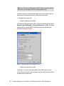
The following steps need to be performed from the HMC console. The Security
Management panel is not available via WebSM:
Choose one of the HMCs as the Certificate Authority. In the main menu of the
HMC, select System Manager Security. Select Certificate Authority, and
then Configure this system as a Web-based System Manager
Certification Authority. A panel will be displayed as shown in Figure 27.
Figure 27 Defining the certificate authority
42
Hardware Management Console (HMC) Case Configuration Study for LPAR Management
For our example, we perform the following actions:
– Enter an organization name: ITSO.
– Verify the certificate expiration date is set to a future date.
– Click the OK button, and a password is requested at the end of the
process. The password is used each time you perform operations on the
Certification Authority Server.
The next step is to generate the authentication keys for the WebSM clients
and servers:
– Private keys will be installed on the HMCs.
– Public keys will be installed on WebSM remote clients.
From the main panel HMC, select System Manager Security, select Certificate
Authority, and then in the right window, Generate Servers Private Key Ring
Files. Enter the password set in the previous step. A new menu is displayed for
defining options as shown in Figure 28.
Figure 28 Generate the private keys ring file
Hardware Management Console (HMC) Case Configuration Study for LPAR Management
43
At this menu:
– Add both HMCs in the list of servers (the current HMC should already be
listed): hmctot184.itso.ibm.com, hmctot182.itso.ibm.com
– Enter the organization name: ITSO.
– Verify that the certificate expiration date is set to a future date.
Install the previous generated private key to the current HMC.
Select System Manager Security → Server Security → Install the private
key ring file for this server. Then select as input device the directory
/var/websm/security/tmp as shown in Figure 29.
Figure 29 Installing the local private key on the HMC
Copy the private key ring file to removable media for installing it to the second
HMC.
Select System Manager Security → Certificate Authority, and in the right
panel, select Copy Servers’ Private Key Ring Files to removable media.
44
Hardware Management Console (HMC) Case Configuration Study for LPAR Management
Figure 30 Copying the private key ring file to removable media
Tip: To transfer the security keys from the HMC, you can use the floppy drive
or a flash memory. Plug the device in the USB port, before running the copy
procedure, and then, it will show up in the menu as shown in Figure 30.
Copy the private key from removable media to the second HMC.
Insert the removable media in the second HMC. From the HMC menu select:
System Manager Security → Server Security. In the right window, select
Install the private key ring file for this server. A new window is displayed for
selecting the removable media containing the private key for the HMC (see
Figure 31 on page 46).
Hardware Management Console (HMC) Case Configuration Study for LPAR Management
45
Figure 31 Installing the private key ring file for the second HMC
Copy the public key ring file to removable media for installing the key file on
the client PC. Select System Manager Security → Certificate Authority,
and in the right panel, select Copy this Certificate Authority Public Key
Ring File to removable media. A dialog panel is displayed (see Figure 32 on
page 47).
46
Hardware Management Console (HMC) Case Configuration Study for LPAR Management
Figure 32 Save the public key ring file to removable media
You will be provided with a second window to specify the format of the file to
be saved. Depending on the platform of the WebSM client, you can select
either:
– HMC or AIX client: A tar archive is created on the selected media.
– PC Client: A regular file is created on the selected media. This option
requires a formatted media.
Note: Two files are saved on the media, containing the public key ring files:
SM.pubkr and smpubkr.zip.
Next, go back to the System Manager Security menu and select Server
Security. Select Configure this system as a Secure WEB based System
Manager Server as shown in Figure 33 on page 48.
Hardware Management Console (HMC) Case Configuration Study for LPAR Management
47
Figure 33 Select the security option for the authentication
Select one of the two options:
– Always use a secure connection: Only an SSL connection is allowed.
– Allow the user to choose secure or unsecure connections: A checkbox is
displayed at the time of connecting the WebSM client to the HMC, allowing
you to choose a secure (SSL) or an unsecure connection.
Verify the status on the HMC to ensure that it is configured and the private
key ring is installed as shown in Figure 34.
Figure 34 Verify the system manager security status
48
Hardware Management Console (HMC) Case Configuration Study for LPAR Management
Next, go to each of your remote clients and copy the PUBLIC key ring file into
the “codebase” directory under WebSM. When you log in via WebSM, you will
get information if the SSL connection is available or not. Verify the checkbox
Enable secure communication” in Figure 35.
Figure 35 WebSM logon panel
Enabling NTP on the HMC
The pSeries and iSeries Hardware Management Console (HMC) supports
Network Time Protocol (NTP) which allows an administrator to synchronize time
across several systems. You can enable it from the command line as follows:
$ chhmc -c xntp -s enable
$ chhmc -c xntp -s add { -a ip-address | -h hostname }
The first line turns on the daemon, and the second specifies the IP address or
hostname of the server to which the HMC will synchronize its time.
Microcode upgrades
The method used to install a new firmware depends on the release level of
firmware which is currently installed on your server.The release of the firmware
can be determined from the firmaware’s filename: 01SFXXX_YYY_ZZZ, where
XXX is the release level.
The microcode update can be performed either by using the HMC or the target
system, when an HMC is not available. The policy for the microcode update can
be changed from the ASMI. For further details, refer to the ASMI Setup Guide at:
http://publib.boulder.ibm.com/infocenter/eserver/v1r2s/en_US/info/iphby/iphby.pdf
Hardware Management Console (HMC) Case Configuration Study for LPAR Management
49
Attention: Before updating the microcode of the system, we recommend to
carefully read the installation notes of the version you plan to install. For
further information, refer to the microcode download for eServer pSeries
systems page at:
http://techsupport.services.ibm.com/server/mdownload
The following procedure is an example of running a microcode update procedure
for a p550 system using the HMC.
In our example, we use a p550 system attached to the HMC. We select the FTP
server method for installing the microcode update from version 01SF220 to the
new version 01SF230. We downloaded the rpm and xml file from the microcode
download Web page and put them on the FTP server. Since we are upgrading to
a new release of firmware, the update is non-concurrent and a system power off
must be performed before starting the upgrade procedure.
At the beginning of the installation procedure, always check for the most updated
version of the HMC code. In our example, we used HMC 4.5. For the latest code
version of the HMC, refer to the Web page:
http://techsupport.services.ibm.com/server/hmc
Steps performed to update the microcode of the p550 system are as follows:
1. Access License Internal Code Updates menus on HMC. In the Management
Area, select License Internal Code Maintenance → Licensed Internal
Code Updates (see Figure 36 on page 51). Select Upgrade Internal
Licensed Code to a new release.
50
Hardware Management Console (HMC) Case Configuration Study for LPAR Management
Figure 36 License Internal Code Updates menus on the HMC
Note: In our example, we choose to upgrade to a new release. When updating
the firmware level at the same release, choose Change Licensed Internal
Code for the same release.
2. Select the target system (see Figure 37) and click OK.
Figure 37 Select the target system
Hardware Management Console (HMC) Case Configuration Study for LPAR Management
51
3. We downloaded the microcode image to an FTP server, so we specify as LIC
Repository FTP Site (Figure 38).
Figure 38 Specify the microcode location
4. In the details window, enter the IP address of the FTP server, username and
password for the access and the location of the microcode image (see
Figure 39). After connecting to the FTP server, a license acceptance window
is displayed. Confirm the license agreement and continue with the next step.
Figure 39 Specify the details for access to the FTP server
Important: Two files must be found at the indicated location:
Microcode image file, in our example: 01SF230_126_120.rpm
The XML file, in our example: 01SF230_126_120.xml
52
Hardware Management Console (HMC) Case Configuration Study for LPAR Management
5. You are provided with a new window which displays the current and the target
release of the firmware (see Figure 40). Click OK to start the upgrade
process.
Figure 40 Upgrade information
The update process might take 20-30 minutes. When the update operation ends,
the status completed is displayed in the status window, as shown in Figure 41.
Figure 41 Update microcode completed
Referenced Web sites
Latest HMC code updates:
http://techsupport.services.ibm.com/server/hmc
Manual pages for the command line interface on HMC for POWER5 systems:
http://techsupport.services.ibm.com/server/hmc/power5/tips/hmc_man_GA5.pdf
A reference page for the command line interface on HMC for POWER4
systems:
http://techsupport.services.ibm.com/server/hmc/power4/tips/mcode/tip001_cli
cmds.html
CoD site:
http://www.ibm.com/servers/eserver/pseries/ondemand/cod/
Hardware Management Console (HMC) Case Configuration Study for LPAR Management
53
Dual HMC cabling on the IBM 9119-595 and 9119-590 Servers:
http://www.redbooks.ibm.com/abstracts/tips0537.html?Open
ASMI setup guide:
http://publib.boulder.ibm.com/infocenter/eserver/v1r2s/en_US/info/iphby/iph
by.pdf
54
Hardware Management Console (HMC) Case Configuration Study for LPAR Management
The team that wrote this Redpaper
This Redpaper was produced by a team of specialists from around the world
working at the International Technical Support Organization, Austin Center.
Dino Quintero is a Consulting IT Specialist at ITSO in Poughkeepsie, New York.
Before joining ITSO, he worked as a Performance Analyst for the Enterprise
Systems Group and as a Disaster Recovery Architect for IBM Global Services.
His areas of expertise include disaster recovery and pSeries clustering solutions.
He is certified on pSeries system administration and pSeries clustering
technologies. He is also an IBM Senior Certified Professional on pSeries
technologies. Currently, he leads technical teams delivering Redbook solutions
on pSeries clustering technologies and delivering technical workshops
worldwide.
Sven Meissner is an IT specialist at Bayer Business Services GmbH in
Germany. He has more than 10 years of experience in AIX. His areas of
expertise include planning, installation and managing of AIX environments
including HMCs, CSM and HACMP™. Sven is an IBM Certified Technical Expert
- pSeries Administration and Support for AIX 5L v 5.2.
Andrei Socoliuc is a Software Support Engineer in IBM Global Services in
Romania. He holds a Master’s degree in Computer Science from Polytechnic
Institute in Bucharest, Romania. He has six years of experience in the pSeries
Clusters field. His areas of expertise include AIX, PSSP, HACMP, TSM, and
Linux. He has written extensive on pSeries Clusters managed by PSSP.
Thanks to the following people for their contributions to this project:
Octavian Lascu
International Technical Support Organization, Austin Center
Tomas Baublys
IBM Germany
Martin Kaemmerling
Bayer Business Services
Shujun Zhou, Brian Croswell
IBM Poughkeepsie
Andy Mclaughin, Bob Foster, Mark Dewalt
IBM Austin
Beth Norris
Motorola, Inc., Tempe, Arizona
Hardware Management Console (HMC) Case Configuration Study for LPAR Management
55
Yvonne Lyon
International Technical Support Organization, Austin Center
56
Hardware Management Console (HMC) Case Configuration Study for LPAR Management
Notices
This information was developed for products and services offered in the U.S.A.
IBM may not offer the products, services, or features discussed in this document in other countries. Consult
your local IBM representative for information on the products and services currently available in your area.
Any reference to an IBM product, program, or service is not intended to state or imply that only that IBM
product, program, or service may be used. Any functionally equivalent product, program, or service that
does not infringe any IBM intellectual property right may be used instead. However, it is the user's
responsibility to evaluate and verify the operation of any non-IBM product, program, or service.
IBM may have patents or pending patent applications covering subject matter described in this document.
The furnishing of this document does not give you any license to these patents. You can send license
inquiries, in writing, to:
IBM Director of Licensing, IBM Corporation, North Castle Drive Armonk, NY 10504-1785 U.S.A.
The following paragraph does not apply to the United Kingdom or any other country where such
provisions are inconsistent with local law: INTERNATIONAL BUSINESS MACHINES CORPORATION
PROVIDES THIS PUBLICATION "AS IS" WITHOUT WARRANTY OF ANY KIND, EITHER EXPRESS OR
IMPLIED, INCLUDING, BUT NOT LIMITED TO, THE IMPLIED WARRANTIES OF NON-INFRINGEMENT,
MERCHANTABILITY OR FITNESS FOR A PARTICULAR PURPOSE. Some states do not allow disclaimer
of express or implied warranties in certain transactions, therefore, this statement may not apply to you.
This information could include technical inaccuracies or typographical errors. Changes are periodically made
to the information herein; these changes will be incorporated in new editions of the publication. IBM may
make improvements and/or changes in the product(s) and/or the program(s) described in this publication at
any time without notice.
Any references in this information to non-IBM Web sites are provided for convenience only and do not in any
manner serve as an endorsement of those Web sites. The materials at those Web sites are not part of the
materials for this IBM product and use of those Web sites is at your own risk.
IBM may use or distribute any of the information you supply in any way it believes appropriate without
incurring any obligation to you.
Information concerning non-IBM products was obtained from the suppliers of those products, their published
announcements or other publicly available sources. IBM has not tested those products and cannot confirm
the accuracy of performance, compatibility or any other claims related to non-IBM products. Questions on
the capabilities of non-IBM products should be addressed to the suppliers of those products.
This information contains examples of data and reports used in daily business operations. To illustrate them
as completely as possible, the examples include the names of individuals, companies, brands, and products.
All of these names are fictitious and any similarity to the names and addresses used by an actual business
enterprise is entirely coincidental.
COPYRIGHT LICENSE:
This information contains sample application programs in source language, which illustrates programming
techniques on various operating platforms. You may copy, modify, and distribute these sample programs in
any form without payment to IBM, for the purposes of developing, using, marketing or distributing application
programs conforming to the application programming interface for the operating platform for which the
sample programs are written. These examples have not been thoroughly tested under all conditions. IBM,
therefore, cannot guarantee or imply reliability, serviceability, or function of these programs. You may copy,
modify, and distribute these sample programs in any form without payment to IBM for the purposes of
developing, using, marketing, or distributing application programs conforming to IBM's application
programming interfaces.
© Copyright IBM Corp. 2005. All rights reserved.
57
This document was created or updated on February 23, 2006.
®
Send us your comments in one of the following ways:
Use the online Contact us review redbook form found at:
ibm.com/redbooks
Send your comments in an e-mail to:
[email protected]
Mail your comments to:
IBM Corporation, International Technical Support Organization
Dept. JN9B Building 905, 11501 Burnet Road
Austin, Texas 78758-3493 U.S.A.
Trademarks
The following terms are trademarks of the International Business Machines Corporation in the United States,
other countries, or both:
Eserver®
Eserver®
Redbooks (logo)
eServer™
iSeries™
pSeries®
™
xSeries®
AIX 5L™
AIX®
HACMP™
IBM®
OpenPower™
POWER™
POWER4™
POWER5™
Redbooks™
The following terms are trademarks of other companies:
Windows, and the Windows logo are trademarks of Microsoft Corporation in the United States, other
countries, or both.
UNIX is a registered trademark of The Open Group in the United States and other countries.
Linux is a trademark of Linus Torvalds in the United States, other countries, or both.
Other company, product, and service names may be trademarks or service marks of others.
58
Hardware Management Console (HMC) Case Configuration Study for LPAR Management, and