1
General-Purpose AC Servo
J2-Super Series
Program Compatible
MODEL
301) MEE
Printed in Japan
This Instruction Manual uses recycled paper.
Specifications subject to change without notice.
J2-Super Series MR-J2S- CL Servo Amplifier Instruction Manual
HEAD OFFICE:MITSUBISHI DENKI BLDG MARUNOUCHI TOKYO 100-8310
MR-J2S- CL
SERVO AMPLIFIER
INSTRUCTION MANUAL
Safety Instructions
(Always read these instructions before using the equipment.)
Do not attempt to install, operate, maintain or inspect the servo amplifier and servo motor until you have read
through this Instruction Manual, Installation guide, Servo motor Instruction Manual and appended documents
carefully and can use the equipment correctly. Do not use the servo amplifier and servo motor until you have a
full knowledge of the equipment, safety information and instructions.
In this Instruction Manual, the safety instruction levels are classified into "WARNING" and "CAUTION".
WARNING
Indicates that incorrect handling may cause hazardous conditions,
resulting in death or severe injury.
CAUTION
Indicates that incorrect handling may cause hazardous conditions,
resulting in medium or slight injury to personnel or may cause physical
damage.
Note that the CAUTION level may lead to a serious consequence according to conditions. Please follow the
instructions of both levels because they are important to personnel safety.
What must not be done and what must be done are indicated by the following diagrammatic symbols:
: Indicates what must not be done. For example, "No Fire" is indicated by
: Indicates what must be done. For example, grounding is indicated by
.
.
In this Instruction Manual, instructions at a lower level than the above, instructions for other functions, and so
on are classified into "POINT".
After reading this installation guide, always keep it accessible to the operator.
A- 1
1. To prevent electric shock, note the following:
WARNING
Before wiring or inspection, switch power off and wait for more than 10 minutes. Then, confirm the voltage
is safe with voltage tester. Otherwise, you may get an electric shock.
Connect the servo amplifier and servo motor to ground.
Any person who is involved in wiring and inspection should be fully competent to do the work.
Do not attempt to wire the servo amplifier and servo motor until they have been installed. Otherwise, you
may get an electric shock.
Operate the switches with dry hand to prevent an electric shock.
The cables should not be damaged, stressed, loaded, or pinched. Otherwise, you may get an electric shock.
2. To prevent fire, note the following:
CAUTION
Do not install the servo amplifier, servo motor and regenerative brake resistor on or near combustibles.
Otherwise a fire may cause.
When the servo amplifier has become faulty, switch off the main servo amplifier power side. Continuous
flow of a large current may cause a fire.
When a regenerative brake resistor is used, use an alarm signal to switch main power off. Otherwise, a
regenerative brake transistor fault or the like may overheat the regenerative brake resistor, causing a fire.
3. To prevent injury, note the follow
CAUTION
Only the voltage specified in the Instruction Manual should be applied to each terminal, Otherwise, a
burst, damage, etc. may occur.
Connect the terminals correctly to prevent a burst, damage, etc.
Ensure that polarity ( ,
) is correct. Otherwise, a burst, damage, etc. may occur.
During power-on or for some time after power-off, do not touch or close a parts (cable etc.) to the servo
amplifier heat sink, regenerative brake resistor, servo motor, etc. Their temperatures may be high and you
may get burnt or a parts may damaged.
A- 2
4. Additional instructions
The following instructions should also be fully noted. Incorrect handling may cause a fault, injury, electric
shock, etc.
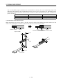
(1) Transportation and installation
CAUTION
Transport the products correctly according to their weights.
Stacking in excess of the specified number of products is not allowed.
Do not carry the servo motor by the cables, shaft or encoder.
Do not hold the front cover to transport the controller. The controller may drop.
Install the servo amplifier in a load-bearing place in accordance with the Instruction Manual.
Do not climb or stand on servo equipment. Do not put heavy objects on equipment.
The controller and servo motor must be installed in the specified direction.
Leave specified clearances between the servo amplifier and control enclosure walls or other equipment.
Do not install or operate the servo amplifier and servo motor which has been damaged or has any parts
missing.
Provide adequate protection to prevent screws and other conductive matter, oil and other combustible
matter from entering the servo amplifier.
Do not drop or strike servo amplifier or servo motor. Isolate from all impact loads.
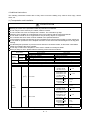
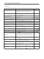
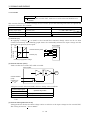
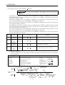
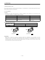
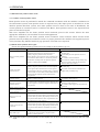
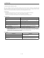
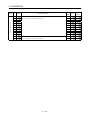
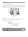
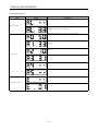
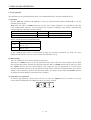
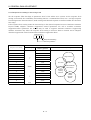
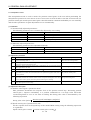
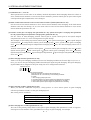
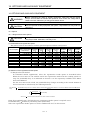
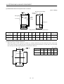
When you keep or use it, please fulfill the following environmental conditions.
Conditions
Servo amplifier
Servo motor
[ ] 0 to 55 (non-freezing)
0 to 40 (non-freezing)
Operation
[ ] 32 to 131 (non-freezing)
32 to 104 (non-freezing)
Ambient
temperature
[ ]
20 to 65 (non-freezing)
15 to 70 (non-freezing)
Storage
[ ]
4 to 149 (non-freezing)
5 to 158 (non-freezing)
Operation
90%RH or less (non-condensing)
80%RH or less (non-condensing)
Ambient
humidity
Storage
90%RH or less (non-condensing)
Ambience
Indoors (no direct sunlight) Free from corrosive gas, flammable gas, oil mist, dust and dirt
Altitude
Max. 1000m (3280 ft) above sea level
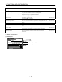
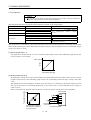
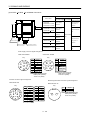
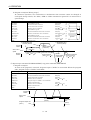
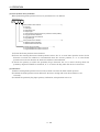
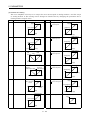
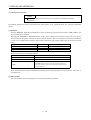
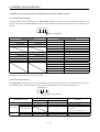
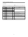
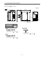
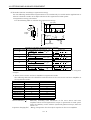
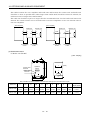
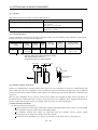
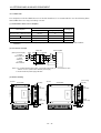
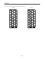
HC-KFS Series
HC-MFS Series
X Y : 49
HC-UFS13 to 73
HC-SFS81
HC-SFS52 to 152
HC-SFS53 to 153
X Y : 24.5
HC-RFS Series
2
[m/s ]
5.9 or less
HC-UFS 72 152
HC-SFS121 201
HC-SFS202 352
X : 24.5
Y : 49
HC-SFS203 353
HC-UFS202
X : 24.5
HC-SFS301
Y : 29.4
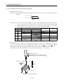
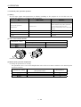
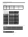
(Note)
Vibration
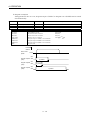
HC-KFS Series
X Y : 161
HC-MFS Series
HC-UFS 13 to 73
HC-SFS81
HC-SFS52 to 152
HC-SFS53 to 153
X Y : 80
HC-RFS Series
2
19.4 or less
[ft/s ]
HC-UFS 72 152
HC-SFS121 201
HC-SFS202 352
X : 80
HC-SFS203 353
Y : 161
HC-UFS202
X : 80
HC-SFS301
Y : 96
Note. Except the servo motor with reduction gear.
Environment
A- 3
CAUTION
Securely attach the servo motor to the machine. If attach insecurely, the servo motor may come off during
operation.
The servo motor with reduction gear must be installed in the specified direction to prevent oil leakage.
For safety of personnel, always cover rotating and moving parts.
Never hit the servo motor or shaft, especially when coupling the servo motor to the machine. The encoder
may become faulty.
Do not subject the servo motor shaft to more than the permissible load. Otherwise, the shaft may break.
When the equipment has been stored for an extended period of time, consult Mitsubishi.
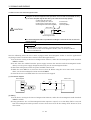
(2) Wiring
CAUTION
Wire the equipment correctly and securely. Otherwise, the servo motor may misoperate.
Do not install a power capacitor, surge absorber or radio noise filter (FR-BIF option) between the servo
motor and servo amplifier.
Connect the output terminals (U, V, W) correctly. Otherwise, the servo motor will operate improperly.
Do not connect AC power directly to the servo motor. Otherwise, a fault may occur.
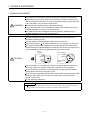
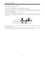
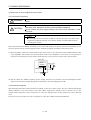
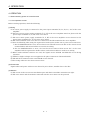
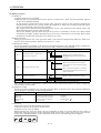
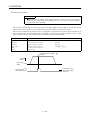
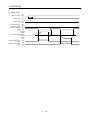
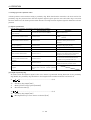
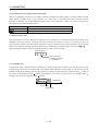
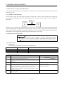
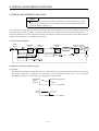
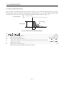
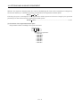
The surge absorbing diode installed on the DC output signal relay must be wired in the specified direction.
Otherwise, the forced stop (EMG) and other protective circuits may not operate.
Servo
amplifier
Servo
amplifier
COM
(24VDC)
COM
(24VDC)
Control
output
signal
Control
output
signal
RA
RA
(3) Test run adjustment
CAUTION
Before operation, check the parameter settings. Improper settings may cause some machines to perform
unexpected operation.
The parameter settings must not be changed excessively. Operation will be insatiable.
A- 4
(4) Usage
CAUTION
Provide an external emergency stop circuit to ensure that operation can be stopped and power switched
off immediately.
Any person who is involved in disassembly and repair should be fully competent to do the work.
Before resetting an alarm, make sure that the run signal is off to prevent an accident. A sudden restart is
made if an alarm is reset with the run signal on.
Do not modify the equipment.
Use a noise filter, etc. to minimize the influence of electromagnetic interference, which may be caused by
electronic equipment used near the servo amplifier.
Use the servo amplifier with the specified servo motor.
The electromagnetic brake on the servo motor is designed to hold the motor shaft and should not be used
for ordinary braking.
For such reasons as service life and mechanical structure (e.g. where a ballscrew and the servo motor are
coupled via a timing belt), the electromagnetic brake may not hold the motor shaft. To ensure safety,
install a stopper on the machine side.
(5) Corrective actions
CAUTION
When it is assumed that a hazardous condition may take place at the occur due to a power failure or a
product fault, use a servo motor with electromagnetic brake or an external brake mechanism for the
purpose of prevention.
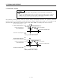
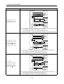
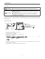
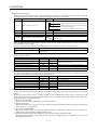
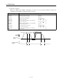
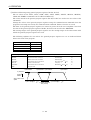
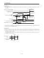
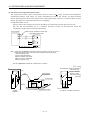
Configure the electromagnetic brake circuit so that it is activated not only by the servo amplifier signals but
also by an external forced stop (EMG).
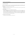
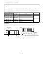
Contacts must be open when
servo-on (SON) is off, when a trouble (ALM) Circuit must be
is present and when an electromagnetic
opened during
brake interlock (MBR).
forced stop (EMG).
Servo motor
RA EMG
24VDC
Electromagnetic brake
When any alarm has occurred, eliminate its cause, ensure safety, and deactivate the alarm before
restarting operation.
When power is restored after an instantaneous power failure, keep away from the machine because the
machine may be restarted suddenly (design the machine so that it is secured against hazard if restarted).
A- 5
(6) Maintenance, inspection and parts replacement
CAUTION
With age, the electrolytic capacitor will deteriorate. To prevent a secondary accident due to a fault, it is
recommended to replace the electrolytic capacitor every 10 years when used in general environment.
Please consult our sales representative.
(7) General instruction
To illustrate details, the equipment in the diagrams of this Specifications and Instruction Manual may have
been drawn without covers and safety guards. When the equipment is operated, the covers and safety
guards must be installed as specified. Operation must be performed in accordance with this Specifications
and Instruction Manual.
About processing of waste
When you discard servo amplifier, a battery (primary battery), and other option articles, please follow the law of
each country (area).
FOR MAXIMUM SAFETY
This product is not designed or manufactured to be used in equipment or systems in situations that can
affect or endanger human life.
When considering this product for operation in special applications such as machinery or systems used in
passenger transportation, medical, aerospace, atomic power, electric power, or submarine repeating
applications, please contact your nearest Mitsubishi sales representative.
Although this product was manufactured under conditions of strict quality control, you are strongly advised
to install safety devices to forestall serious accidents when it is used in facilities where a breakdown in the
product is likely to cause a serious accident.
EEP-ROM life
The number of write times to the EEP-ROM, which stores parameter settings, etc., is limited to 100,000. If
the total number of the following operations exceeds 100,000, the servo amplifier and/or converter unit may
fail when the EEP-ROM reaches the end of its useful life.
Write to the EEP-ROM due to parameter setting changes
Home position setting in the absolute position detection system
Write to the EEP-ROM due to device changes
Write to the EEP-ROM due to program changes
A- 6
COMPLIANCE WITH EC DIRECTIVES
1. WHAT ARE EC DIRECTIVES?
The EC directives were issued to standardize the regulations of the EU countries and ensure smooth
distribution of safety-guaranteed products. In the EU countries, the machinery directive (effective in
January, 1995), EMC directive (effective in January, 1996) and low voltage directive (effective in January,
1997) of the EC directives require that products to be sold should meet their fundamental safety
requirements and carry the CE marks (CE marking). CE marking applies to machines and equipment
into which servo amplifiers have been installed.
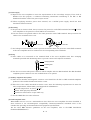
(1) EMC directive
The EMC directive applies not to the servo units alone but to servo-incorporated machines and
equipment. This requires the EMC filters to be used with the servo-incorporated machines and
equipment to comply with the EMC directive. For specific EMC directive conforming methods, refer to
the EMC Installation Guidelines (IB(NA)67310).
(2) Low voltage directive
The low voltage directive applies also to servo units alone. Hence, they are designed to comply with
the low voltage directive.
This servo is certified by TUV, third-party assessment organization, to comply with the low voltage
directive.
(3) Machine directive
Not being machines, the servo amplifiers need not comply with this directive.
2. PRECAUTIONS FOR COMPLIANCE
(1) Servo amplifiers and servo motors used
Use the servo amplifiers and servo motors which comply with the standard model.
Servo amplifier series :MR-J2S-10CL to MR-J2S-700CL
MR-J2S-10CL1 to MR-J2S40CL1
Servo motor series
:HC-KFS
HC-MFS
HC-SFS
HC-RFS
HC-UFS
HA-LFS
HC-LFS
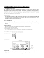
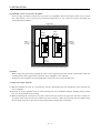
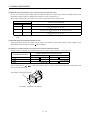
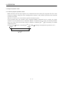
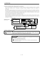
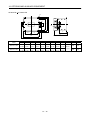
(2) Configuration
Control box
Reinforced
insulating type
Reinforced
insulating
transformer
No-fuse
breaker
Magnetic
contactor
NFB
MC
24VDC
power
supply
Servo
amplifier
Servo
motor
SM
(3) Environment
Operate the servo amplifier at or above the contamination level 2 set forth in IEC664. For this
purpose, install the servo amplifier in a control box which is protected against water, oil, carbon, dust,
dirt, etc. (IP54).
A- 7
(4) Power supply
(a) Operate the servo amplifier to meet the requirements of the overvoltage category II set forth in
IEC664. For this purpose, a reinforced insulating transformer conforming to the IEC or EN
Standard should be used in the power input section.
(b) When supplying interface power from external, use a 24VDC power supply which has been
insulation-reinforced in I/O.
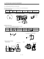
(5) Grounding
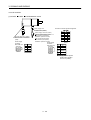
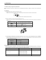
(a) To prevent an electric shock, always connect the protective earth (PE) terminals (marked
servo amplifier to the protective earth (PE) of the control box.
) of the
(b) Do not connect two ground cables to the same protective earth (PE) terminal. Always connect the
cables to the terminals one-to-one.
PE terminals
PE terminals
(c) If a leakage current breaker is used to prevent an electric shock, the protective earth (PE) terminals
of the servo amplifier must be connected to the corresponding earth terminals.
(6) Wiring
(a) The cables to be connected to the terminal block of the servo amplifier must have crimping
terminals provided with insulating tubes to prevent contact with adjacent terminals.
Crimping terminal
Insulating tube
Cable
(b) Use the servo motor side power connector which complies with the EN Standard. The EN Standard
compliant power connector sets are available from us as options.
(7) Auxiliary equipment and options
(a) The no-fuse breaker and magnetic contactor used should be the EN or IEC standard-compliant
products of the models described in Section 14.2.2.
(b) The sizes of the cables described in Section 14.2.1 meet the following requirements. To meet the
other requirements, follow Table 5 and Appendix C in EN60204-1.
Ambient temperature: 40 (104) [ ( )]
Sheath: PVC (polyvinyl chloride)
Installed on wall surface or open table tray
(c) Use the EMC filter for noise reduction.
(8) Performing EMC tests
When EMC tests are run on a machine/device into which the servo amplifier has been installed, it
must conform to the electromagnetic compatibility (immunity/emission) standards after it has
satisfied the operating environment/electrical equipment specifications.
For the other EMC directive guidelines on the servo amplifier, refer to the EMC Installation
Guidelines(IB(NA)67310).
A- 8
CONFORMANCE WITH UL/C-UL STANDARD
(1) Servo amplifiers and servo motors used
Use the servo amplifiers and servo motors which comply with the standard model.
Servo amplifier series :MR-J2S-10CL to MR-J2S-700CL
MR-J2S-10CL1 to MR-J2S-40CL1
Servo motor series
:HC-KFS
HC-MFS
HC-SFS
HC-RFS
HC-UFS
HA-LFS
HC-LFS
(2) Installation
Install a fan of 100CFM (2.8m3/min) air flow 4 [in] (10.16 [cm]) above the servo amplifier or provide
cooling of at least equivalent capability.
(3) Short circuit rating
This servo amplifier conforms to the circuit whose peak current is limited to 5000A or less. Having
been subjected to the short-circuit tests of the UL in the alternating-current circuit, the servo
amplifier conforms to the above circuit.
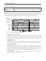
(4) Capacitor discharge time
The capacitor discharge time is as listed below. To ensure safety, do not touch the charging section for
10 minutes after power-off.
Servo amplifier
Discharge time [min]
MR-J2S-10CL(1) 20CL(1)
MR-J2S-40CL(1) 60CL
MR-J2S-70CL to 350CL
MR-J2S-500CL 700CL
1
2
3
5
(5) Options and auxiliary equipment
Use UL/C-UL standard-compliant products.
(6) Attachment of a servo motor
For the flange size of the machine side where the servo motor is installed, refer to “CONFORMANCE
WITH UL/C-UL STANDARD” in the Servo Motor Instruction Manual.
(7) About wiring protection
For installation in United States, branch circuit protection must be provided, in accordance with the
National Electrical Code and any applicable local codes.
For installation in Canada, branch circuit protection must be provided, in accordance with the Canada
Electrical Code and any applicable provincial codes.
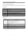
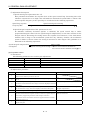
<<About the manuals>>
This Instruction Manual and the MELSERVO Servo Motor Instruction Manual are required if you use
the MR-J2S-CL for the first time. Always purchase them and use the MR-J2S-CL safely.
Relevant manuals
Manual name
Manual No.
MELSERVO Servo Motor Instruction Manual
EMC Installation Guidelines
SH(NA)3181
IB(NA)67310
A- 9
MEMO
A - 10
CONTENTS
1. FUNCTIONS AND CONFIGURATION
1- 1 to 1-24
1.1 Introduction.............................................................................................................................................. 1- 1
1.1.1 Function block diagram.................................................................................................................... 1- 2
1.1.2 System configuration........................................................................................................................ 1- 3
1.1.3 I/O devices ......................................................................................................................................... 1- 8
1.2 Servo amplifier standard specifications ................................................................................................ 1- 9
1.3 Function list ............................................................................................................................................ 1-11
1.4 Model code definition ............................................................................................................................. 1-12
1.5 Combination with servo motor.............................................................................................................. 1-13
1.6 Structure.................................................................................................................................................. 1-14
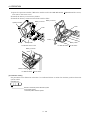
1.6.1 Part names ....................................................................................................................................... 1-14
1.6.2 Removal and reinstallation of the front cover .............................................................................. 1-18
1.7 Servo system with auxiliary equipment............................................................................................... 1-20
2. INSTALLATION
2- 1 to 2- 4
2.1 Environmental conditions....................................................................................................................... 2- 1
2.2 Installation direction and clearances .................................................................................................... 2- 2
2.3 Keep out foreign materials ..................................................................................................................... 2- 3
2.4 Cable stress .............................................................................................................................................. 2- 4
3. SIGNALS AND WIRING
3- 1 to 3-36
3.1 Standard connection example ................................................................................................................ 3- 2
3.2 Internal connection diagram of servo amplifier ................................................................................... 3- 4
3.3 I/O signals................................................................................................................................................. 3- 5
3.3.1 Connectors and signal arrangements............................................................................................. 3- 5
3.3.2 Signal (devices) explanations .......................................................................................................... 3- 6
3.4 Detailed description of signals (devices)............................................................................................... 3-13
3.4.1 Forward rotation start Reverse rotation start Temporary stop/Restart................................ 3-13
3.4.2 Movement complete......................................................................................................................... 3-14
3.4.3 Override ............................................................................................................................................ 3-15
3.4.4 Torque limit...................................................................................................................................... 3-16
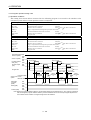
3.5 Alarm occurrence timing chart ............................................................................................................. 3-18
3.6 Interfaces................................................................................................................................................. 3-19
3.6.1 Common line .................................................................................................................................... 3-19
3.6.2 Detailed description of the interfaces ............................................................................................ 3-20
3.7 Input power supply circuit..................................................................................................................... 3-23
3.7.1 Connection example......................................................................................................................... 3-23
3.7.2 Terminals.......................................................................................................................................... 3-25
3.7.3 Power-on sequence........................................................................................................................... 3-26
3.8 Connection of servo amplifier and servo motor ................................................................................... 3-27
3.8.1 Connection instructions .................................................................................................................. 3-27
3.8.2 Connection diagram......................................................................................................................... 3-27
3.8.3 I/O terminals .................................................................................................................................... 3-29
1
3.9 Servo motor with electromagnetic brake ............................................................................................. 3-31
3.10 Grounding ............................................................................................................................................. 3-34
3.11 Servo amplifier terminal block (TE2) wiring method ....................................................................... 3-35
3.12 Instructions for the 3M connector....................................................................................................... 3-36
4. OPERATION
4- 1 to 4-50
4.1 When switching power on for the first time.......................................................................................... 4- 1
4.1.1 Pre-operation checks ........................................................................................................................ 4- 1
4.1.2 Startup ............................................................................................................................................... 4- 2
4.2 Program operation mode......................................................................................................................... 4- 5
4.2.1 What is program operation mode? .................................................................................................. 4- 5
4.2.2 Programming language.................................................................................................................... 4- 6
4.2.3 Basic setting of signals and parameters........................................................................................ 4-25
4.2.4 Program operation timing chart .................................................................................................... 4-26
4.3 Manual operation mode ......................................................................................................................... 4-27
4.3.1 Jog operation .................................................................................................................................... 4-27
4.3.2 Manual pulse generator operation................................................................................................. 4-29
4.4 Manual home position return mode ..................................................................................................... 4-31
4.4.1 Outline of home position return ..................................................................................................... 4-31
4.4.2 Dog type home position return ....................................................................................................... 4-33
4.4.3 Count type home position return ................................................................................................... 4-35
4.4.4 Data setting type home position return ........................................................................................ 4-36
4.4.5 Stopper type home position return ................................................................................................ 4-37
4.4.6 Home position ignorance (servo-on position defined as home position)..................................... 4-38
4.4.7 Dog type rear end reference home position return....................................................................... 4-39
4.4.8 Count type front end reference home position return.................................................................. 4-40
4.4.9 Dog cradle type home position return ........................................................................................... 4-41
4.4.10 Home position return automatic return function....................................................................... 4-42
4.5 Absolute position detection system....................................................................................................... 4-43
4.6 Serial communication operation ........................................................................................................... 4-46
4.6.1 Positioning operation in accordance with programs .................................................................... 4-46
4.6.2 Multidrop system............................................................................................................................. 4-46
4.6.3 Group designation............................................................................................................................ 4-47
4.7 Incremental value command system .................................................................................................... 4-49
5. PARAMETERS
5- 1 to 5-26
5.1 Parameter list .......................................................................................................................................... 5- 1
5.1.1 Parameter write inhibit ................................................................................................................... 5- 1
5.1.2 List ..................................................................................................................................................... 5- 2
5.2 Detailed explanation .............................................................................................................................. 5-21
5.2.1 Electronic gear ................................................................................................................................. 5-21
5.2.2 Changing the status display screen............................................................................................... 5-22
5.2.3 S-pattern acceleration/deceleration ............................................................................................... 5-23
5.2.4 Analog output................................................................................................................................... 5-23
5.2.5 Changing the stop pattern using a limit switch ........................................................................... 5-25
2
5.2.6 Alarm history clear.......................................................................................................................... 5-25
5.2.7 Software limit................................................................................................................................... 5-25
6. SERVO CONFIGURATION SOFTWARE
6- 1 to 6-24
6.1 Specifications ........................................................................................................................................... 6- 1
6.2 System configuration............................................................................................................................... 6- 1
6.3 Station setting.......................................................................................................................................... 6- 3
6.4 Parameters ............................................................................................................................................... 6- 4
6.5 Simple Program ....................................................................................................................................... 6- 6
6.5.1 Program data..................................................................................................................................... 6- 6
6.5.2 Indirect addressing........................................................................................................................... 6- 9
6.6 Device assignment method .................................................................................................................... 6-11
6.7 Test operation ......................................................................................................................................... 6-15
6.7.1 Jog operation .................................................................................................................................... 6-15
6.7.2 Positioning operation....................................................................................................................... 6-17
6.7.3 Motor-less operation ........................................................................................................................ 6-19
6.7.4 Output signal (DO) forced output .................................................................................................. 6-20
6.7.5 Program test operation ................................................................................................................... 6-21
6.8 Alarm history .......................................................................................................................................... 6-23
7. DISPLAY AND OPERATION
7- 1 to 7-20
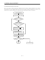
7.1 Display flowchart..................................................................................................................................... 7- 1
7.2 Status display .......................................................................................................................................... 7- 2
7.2.1 Display transition ............................................................................................................................. 7- 2
7.2.2 Display examples .............................................................................................................................. 7- 3
7.2.3 Status display list ............................................................................................................................. 7- 4
7.3 Diagnosis mode ........................................................................................................................................ 7- 5
7.3.1 Display transition ............................................................................................................................. 7- 5
7.3.2 Diagnosis mode list........................................................................................................................... 7- 6
7.4 Alarm mode .............................................................................................................................................. 7- 8
7.4.1 Display transition ............................................................................................................................. 7- 8
7.4.2 Alarm mode list................................................................................................................................. 7- 9
7.5 Parameter mode ..................................................................................................................................... 7-11
7.5.1 Parameter mode transition............................................................................................................. 7-11
7.5.2 Operation example........................................................................................................................... 7-12
7.6 External I/O signal display.................................................................................................................... 7-14
7.7 Output signal (DO) forced output ......................................................................................................... 7-15
7.8 Test operation mode ............................................................................................................................... 7-16
7.8.1 Mode change..................................................................................................................................... 7-16
7.8.2 Jog operation .................................................................................................................................... 7-17
7.8.3 Positioning operation....................................................................................................................... 7-18
7.8.4 Motor-less operation ........................................................................................................................ 7-19
3
8. GENERAL GAIN ADJUSTMENT
8- 1 to 8-12
8.1 Different adjustment methods ............................................................................................................... 8- 1
8.1.1 Adjustment on a single servo amplifier.......................................................................................... 8- 1
8.1.2 Adjustment using servo configuration software............................................................................ 8- 2
8.2 Auto tuning .............................................................................................................................................. 8- 3
8.2.1 Auto tuning mode ............................................................................................................................. 8- 3
8.2.2 Auto tuning mode operation ............................................................................................................ 8- 4
8.2.3 Adjustment procedure by auto tuning............................................................................................ 8- 5
8.2.4 Response level setting in auto tuning mode................................................................................... 8- 6
8.3 Manual mode 1 (simple manual adjustment)....................................................................................... 8- 7
8.3.1 Operation of manual mode 1 ........................................................................................................... 8- 7
8.3.2 Adjustment by manual mode 1 ....................................................................................................... 8- 7
8.4 Interpolation mode ................................................................................................................................. 8-10
8.5 Differences in auto tuning between MELSERVO-J2 and MELSERVO-J2-Super .......................... 8-11
8.5.1 Response level setting ..................................................................................................................... 8-11
8.5.2 Auto tuning selection....................................................................................................................... 8-11
9. SPECIAL ADJUSTMENT FUNCTIONS
9- 1 to 9-10
9.1 Function block diagram .......................................................................................................................... 9- 1
9.2 Machine resonance suppression filter ................................................................................................... 9- 1
9.3 Adaptive vibration suppression control................................................................................................. 9- 3
9.4 Low-pass filter ......................................................................................................................................... 9- 4
9.5 Gain changing function........................................................................................................................... 9- 5
9.5.1 Applications....................................................................................................................................... 9- 5
9.5.2 Function block diagram.................................................................................................................... 9- 5
9.5.3 Parameters ........................................................................................................................................ 9- 6
9.5.4 Gain changing operation.................................................................................................................. 9- 8
10. INSPECTION
10- 1 to 10- 2
11. TROUBLESHOOTING
11- 1 to 11-10
11.1 Trouble at start-up .............................................................................................................................. 11- 1
11.1.1 Position control mode ................................................................................................................... 11- 1
11.2 When alarm or warning has occurred ............................................................................................... 11- 2
11.2.1 Alarms and warning list .............................................................................................................. 11- 2
11.2.2 Remedies for alarms..................................................................................................................... 11- 3
11.2.3 Remedies for warnings................................................................................................................. 11- 9
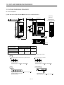
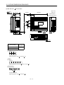
12. OUTLINE DIMENSION DRAWINGS
12- 1 to 12- 8
12.1 Servo amplifiers................................................................................................................................... 12- 1
12.2 Connectors............................................................................................................................................ 12- 6
4
13. CHARACTERISTICS
13- 1 to 13- 8
13.1 Overload protection characteristics ................................................................................................... 13- 1
13.2 Power supply equipment capacity and generated loss .................................................................... 13- 2
13.3 Dynamic brake characteristics........................................................................................................... 13- 4
13.4 Encoder cable flexing life .................................................................................................................... 13- 6
13.5 Inrush Currents at Power-On of Main Circuit and Control Circuit .............................................. 13- 7
14. OPTIONS AND AUXILIARY EQUIPMENT
14- 1 to 14-44
14.1 Options.................................................................................................................................................. 14- 1
14.1.1 Regenerative brake options ......................................................................................................... 14- 1
14.1.2 Brake unit...................................................................................................................................... 14- 9
14.1.3 Power return converter ............................................................................................................... 14-11
14.1.4 Cables and connectors................................................................................................................. 14-14
14.1.5 Junction terminal block (MR-TB20) .......................................................................................... 14-22
14.1.6 Maintenance junction card (MR-J2CN3TM) ............................................................................ 14-24
14.1.7 External digital display (MR-DP60) .......................................................................................... 14-26
14.1.8 Manual pulse generator (MR-HDP01) ...................................................................................... 14-28
14.1.9 Battery (MR-BAT, A6BAT)......................................................................................................... 14-29
14.2 Auxiliary equipment .......................................................................................................................... 14-30
14.2.1 Recommended wires .................................................................................................................... 14-30
14.2.2 No-fuse breakers, fuses, magnetic contactors........................................................................... 14-32
14.2.3 Power factor improving reactors ................................................................................................ 14-32
14.2.4 Relays............................................................................................................................................ 14-33
14.2.5 Surge absorbers ........................................................................................................................... 14-33
14.2.6 Noise reduction techniques......................................................................................................... 14-33
14.2.7 Leakage current breaker............................................................................................................. 14-39
14.2.8 EMC filter..................................................................................................................................... 14-41
14.2.9 Setting potentiometers for analog inputs.................................................................................. 14-43
15. COMMUNICATION FUNCTIONS
15- 1 to 15-36
15.1 Configuration ....................................................................................................................................... 15- 1
15.1.1 RS-422 configuration.................................................................................................................... 15- 1
15.1.2 RS-232C configuration ................................................................................................................. 15- 2
15.2 Communication specifications............................................................................................................ 15- 3
15.2.1 Communication overview............................................................................................................. 15- 3
15.2.2 Parameter setting ......................................................................................................................... 15- 4
15.3 Protocol ................................................................................................................................................. 15- 5
15.4 Character codes ................................................................................................................................... 15- 7
15.5 Error codes ........................................................................................................................................... 15- 8
15.6 Checksum ............................................................................................................................................. 15- 8
15.7 Time-out operation .............................................................................................................................. 15- 9
15.8 Retry operation .................................................................................................................................... 15- 9
15.9 Initialization........................................................................................................................................ 15-10
15.10 Communication procedure example ............................................................................................... 15-10
5
15.11 Command and data No. list............................................................................................................. 15-11
15.11.1 Read commands ......................................................................................................................... 15-11
15.11.2 Write commands ........................................................................................................................ 15-14
15.12 Detailed explanations of commands............................................................................................... 15-16
15.12.1 Data processing.......................................................................................................................... 15-16
15.12.2 Status display ............................................................................................................................ 15-18
15.12.3 Parameter................................................................................................................................... 15-19
15.12.4 External I/O signal statuses..................................................................................................... 15-21
15.12.5 Device ON/OFF.......................................................................................................................... 15-23
15.12.6 Disable/enable of I/O devices (DIO) ......................................................................................... 15-24
15.12.7 Input devices ON/OFF (test operation) ................................................................................... 15-25
15.12.8 Test operation mode .................................................................................................................. 15-26
15.12.9 Output signal pin ON/OFF output signal (DO) forced output.............................................. 15-29
15.12.10 Alarm history ........................................................................................................................... 15-30
15.12.11 Current alarm .......................................................................................................................... 15-31
15.12.12 Current position latch data .................................................................................................... 15-32
15.12.13 General-purpose register ........................................................................................................ 15-33
15.12.14 Servo amplifier group designation......................................................................................... 15-35
15.12.15 Software version ...................................................................................................................... 15-36
Appendix
App- 1 to App- 2
App 1. Status indication block diagram ................................................................................................. App- 1
App 2. Junction terminal block (MR-TB20) terminal block labels ...................................................... App- 2
6
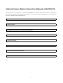
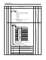
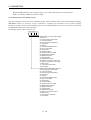
Optional Servo Motor Instruction Manual CONTENTS
The rough table of contents of the optional MELSERVO Servo Motor Instruction Manual is introduced
here for your reference. Note that the contents of the Servo Motor Instruction Manual are not included in
the Servo Amplifier Instruction Manual.
1. INTRODUCTION
2. INSTALLATION
3. CONNECTORS USED FOR SERVO MOTOR WIRING
4. INSPECTION
5. SPECIFICATIONS
6. CHARACTERISTICS
7. OUTLINE DIMENSION DRAWINGS
8. CALCULATION METHODS FOR DESIGNING
7
MEMO
8
1. FUNCTIONS AND CONFIGURATION
1. FUNCTIONS AND CONFIGURATION
1.1 Introduction
The MR-J2S-CL program-compatible AC servo amplifier is based on the MR-J2S-CP AC servo amplifier
with built-in positioning functions and incorporates program-driven, single-axis positioning functions.
These functions perform positioning operation by creating the position data (target positions), servo motor
speeds, acceleration and deceleration time constants, etc. as a program and executing the program. The
servo amplifier is the most appropriate to configure a simple positioning system or to simplify a system,
for example.
Up to 16 programs can be created. The program capacity is 120 steps as a total of all programs.
All servo motors are equipped with an absolute position encoder as standard. An absolute position
detection system can be configured by merely adding a battery to the servo amplifier. Once the home
position has been set, home position return is not required at power on, alarm occurrence, etc.
1- 1
1. FUNCTIONS AND CONFIGURATION
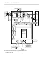
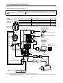
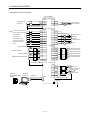
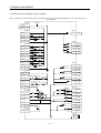
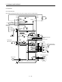
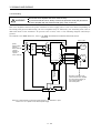
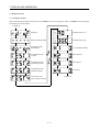
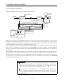
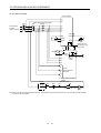
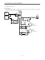
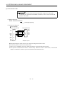
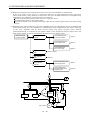
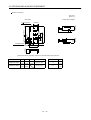
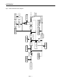
1.1.1 Function block diagram
The function block diagram of this servo is shown below.
Regenerative brake option
(Note3)
Servo amplifier
P
C
D
NFB
DS
MC
(Note1)
RA
L1
L2
Regenerative
brake
transistor
L3
Current
detector
CHARGE
lamp
U
V
V
W
W
E1
Control
power
supply
L21
Regenerative
brake
SM
Dynamic
brake
Fan
(MR-J2S-200CP or more)
L11
U
E2
Base
amplifier
Voltage
detection
Overcurrent
protection
Current
detection
Electromagnetic
brake
CN2
(Note2)
Power
supply
3-phase
200 to
230VAC,
or
1-phase
100 to
120VAC
Servo motor
Encoder
Model adaptive control
Current
control
Program
SPN (1000)
STA (200)
STB (300)
MOV (500)
SPN (1000)
MOVA (1000)
MOVA (0)
Speed
control
Position
control
STOP
MR-BAT
CON1
Position
command
creation
RS-232C
RS-422
A/D
CN1A
I/F
CN1B
Optional battery
(for absolute position
detection system)
D/A
CN3
Analog monitor
(2 channels)
Analog
(2 channels)
Controller
D I/O control
Servo on
Start
Failure, etc.
RS-422/RS-232C
To other servo
amplifier
Note:1. The built-in regenerative brake resistor is not provided for the MR-J2S-10CL (1).
2. For 1-phase 230VAC, connect the power supply to L1,L2 and leave L3 open.
L3 is not provided for a 1-phase 100 to120VAC power supply.
3. For MR-J2S-350CL or less.
1- 2
1. FUNCTIONS AND CONFIGURATION
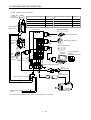
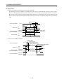
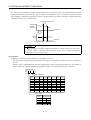
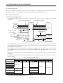
1.1.2 System configuration
This section describes operations using this servo.
You can arrange any configurations from a single-axis to max. 32-axis systems. Further, the connector
pins in the interface section allow you to assign the optimum signals to respective systems. (Refer to
Sections 1.1.3 and 3.3.3.) The Servo configuration Software (refer to Chapter 6) and personal computer
are required to change or assign devices.
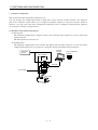
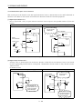
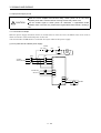
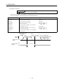
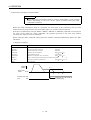
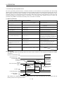
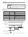
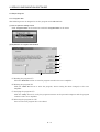
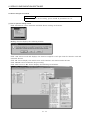
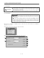
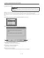
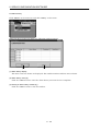
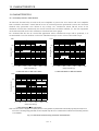
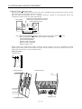
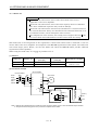
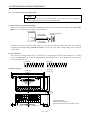
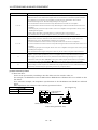
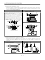
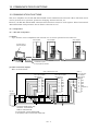
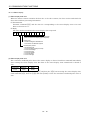
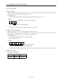
(1) Operation using external input signals
(a) Description
The following configuration example assumes that external input signals are used to control all
signals (devices).
The I/O signals are as factory-set.
(b) Configuration
The following configuration uses external I/O signals. The personal computer is used with Servo
configuration Software to set creation of a program, change and monitor the parameters.
Personal
computer
External I/O
signals
Servo amplifier
CN1A CN1B
RS–232C
CN2 CN3
Power supply
Servo motor
1- 3
Servo configuration
Software
1. FUNCTIONS AND CONFIGURATION
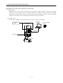
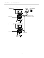
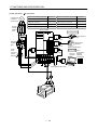
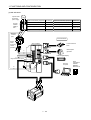
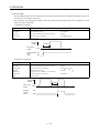
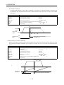
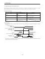
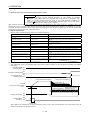
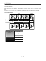
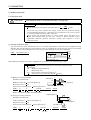
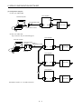
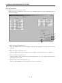
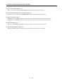
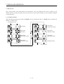
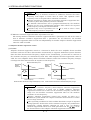
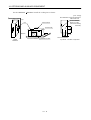
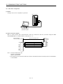
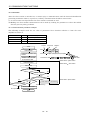
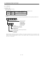
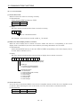
(2) Operation using external input signals and communication
(a) Description
Communication can be used to Selection of the program, change parameter values, and confirm
monitor data, for example. Enter a forward rotation start (ST1) or reverse rotation start (ST2)
through the external I/O. Use this system when position data/speed setting or the host personal
computer or the like is used to change the parameter values, for example.
(b) Configuration
1) One servo amplifier is connected with the personal computer by RS-232C.
Personal
computer
External I/O
signals
Servo amplifier
CN1A CN1B
RS–232C
CN2 CN3
Power supply
Servo motor
1- 4
Servo configuration
Software
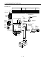
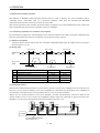
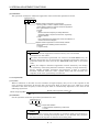
1. FUNCTIONS AND CONFIGURATION
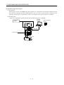
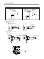
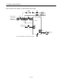
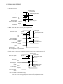
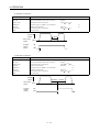
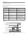
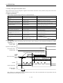
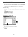
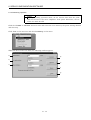
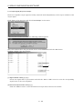
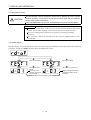
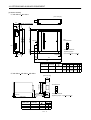
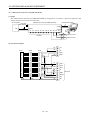
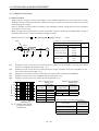
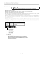
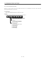
2) Several (up to 32) servo amplifiers are connected with the personal computer by RS-422.
Use parameter No. 16 to change the communication system.
Personal
computer
External I/O
signals
Servo amplifier (axis 1)
Servo configuration
Software
CN1A CN1B
RS–232C
RS–422
RS–232C/RS-422 converter
(to be prepared by the customer)
CN2 CN3
Power supply
Servo motor
RS–422
External I/O
signals
Servo amplifier (axis 2)
CN1A CN1B
CN2 CN3
Power supply
To the next axis
Servo motor
1- 5
1. FUNCTIONS AND CONFIGURATION
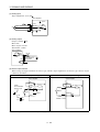
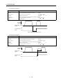
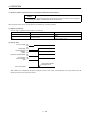
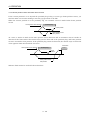
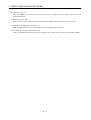
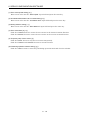
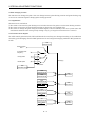
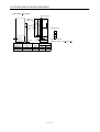
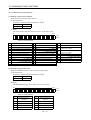
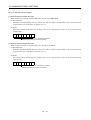
(3) Operation using communication
(a) Description
Analog input, forced stop (EMG) and other signals are controlled by external I/O signals and the
other devices controlled through communication. Also, you can set each program, selection of the
program, and change or set parameter values, for example. Up to 32 axes may be controlled.
(b) Configuration
1) One servo amplifier is connected with the personal computer by RS-232C.
Personal
computer
External I/O
signals
Servo amplifier
CN1A CN1B
RS–232C
CN2 CN3
Power supply
Servo motor
1- 6
Servo configuration
Software
1. FUNCTIONS AND CONFIGURATION
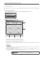
2) Several (up to 32) servo amplifiers are connected with the personal computer by RS-422.
Use parameter No. 16 to change the communication system.
Personal
computer
External I/O
signals
Servo amplifier (axis 1)
Servo configuration
Software
CN1A CN1B
RS–232C
RS–422
RS–232C/RS-422 converter
(to be prepared by the customer)
CN2 CN3
Power supply
Servo motor
RS–422
External I/O
signals
Servo amplifier (axis 2)
CN1A CN1B
CN2 CN3
Power supply
To the next axis
Servo motor
1- 7
1. FUNCTIONS AND CONFIGURATION
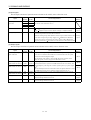
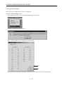
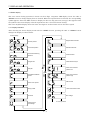
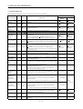
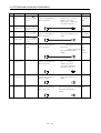
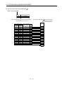
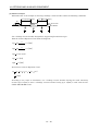
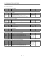
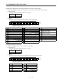
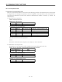
1.1.3 I/O devices
This servo amplifier allows devices to be allocated to the pins of connector CN1A/CN1B as desired. The
following devices can be allocated. For device details, refer to Section 3.3.2.
Symbol
Factoryallocated pin
Servo-on
SON
CN1A-19
Trouble
Reset
RES
CN1B-15
Ready
Input device
Output device
Symbol
Factoryallocated pin
ALM
CN1B-18
RD
CN1B-19
Forward rotation stroke end
LSP
CN1B-16
Movement complete
PED
CN1B-6
Reverse rotation stroke end
LSN
CN1B-17
Zeroing completion
ZP
CN1A-18
Forward rotation start
ST1
CN1B-7
Program output 1
OUT1
CN1B-4
Reverse rotation start
ST2
Program output 2
OUT2
Proximity dog
DOG
Program output 3
OUT3
Program No. selection 1
DI0
CN1B-5
Electromagnetic brake interlock
MBR
Program No. selection 2
DI1
CN1B-14
Position range
POT
Program No. selection 3
DI2
Warning
WNG
Program No. selection 4
CN1A-8
DI3
Battery warning
BWNG
Forced stop
EMG
Limiting torque
TLC
Automatic/manual selection
MD0
Temporary stop
Override selection
OVR
SYNC synchronous output
External torque limit selection
TL
Internal torque limit selection
TL2
Proportion control
PC
Temporary stop/restart
STP
Manual pulse generator
multiplication 1
TP0
Manual pulse generator
multiplication 2
TP1
Gain switch
CDP
Current position latch input
LPS
Program input 1
PI1
CN1B-8
Program input 2
PI2
CN1B-9
Program input 3
PI3
1- 8
PUS
SOUT
1. FUNCTIONS AND CONFIGURATION
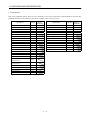
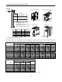
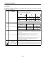
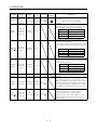
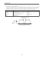
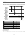
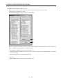
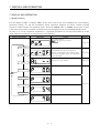
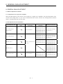
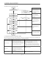
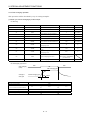
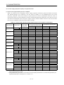
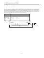
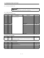
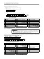
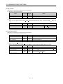
1.2 Servo amplifier standard specifications
Servo amplifier
MR-J2S10CL
20CL
40CL
60CL
70CL
100CL 200CL 350CL 500CL 700CL 10CL1 20CL1 40CL1
Power supply
Item
Voltage/frequency
3-phase 200 to 230VAC, 50/60Hz
or 1-phase 230VAC, 50/60Hz
3-phase 200 to 230VAC, 50/60Hz
1-phase 100 to
120VAC 50/60Hz
Permissible voltage fluctuation
3-phase 200 to 230VAC:
170 to 253VAC
1-phase 230VAC: 207 to 253VAC
3-phase 170 to 253VAC
1-phase
85 to 127VAC
Permissible frequency fluctuation
Within 5%
Power supply capacity
System
Refer to Section13.2
Sine-wave PWM control, current control system
Dynamic brake
Built-in
Operational
specifications
Overcurrent shut-off, regenerative overvoltage shut-off, overload shut-off (electronic
thermal relay), servo motor overheat protection, encoder error protection, regenerative
brake error protection, undervoltage, instantaneous power failure protection, overspeed
protection, excessive error protection
Programming language (Programming with Servo-configuration software).
Programming capacity: 120 steps
Position
command input
Setting by programming language.
Movement setting range at 1 point: 1[ m] to 999.999[mm]
Command system
Protective functions
Programming
Speed command
input
System
Program operation mode
Operation mode
Manual
operation
mode
Jog
Manual pulse
generator
Dog type
Manual
home
position
return
mode
Count type
Data setting type
Stopper type
Servo motor speed, acceleration/deceleration time constant and S-pattern
acceleration/deceleration time constant by programming language.
S-pattern acceleration/deceleration time constant can set by parameter No.14 or by
programming.
Signed absolute value command (signed incremental value command system can be
specified), signed incremental value command system
Setting by programming language
Jog operation is performed in accordance with the parameter-set speed command by
contact input or through RS-422 (232C) communication.
Manual feed is made by manual pulse generator.
Command pulse multiplication: 1, 10 or 100 is selected using parameter.
Home position return is made starting with Z-phase pulse after passage of proximity dog.
Home position address may be set. Home position shift distance may be set. Home position
return direction may be selected.
Automatic at-dog home position return, Automatic stroke return function
Home position return is made by counting encoder pulses after contact with proximity dog.
Home position address may be set. Home position shift value may be set. Home position
return direction may be set.
Automatic at-dog home position return, Automatic stroke return function
Home position return is made without dog.
Home position may be set at any position by manual operation, etc. Home position address
may be set.
Home position return is made by pressing machine part against stroke end.
Home position address may be set. Home position return direction may be set.
1- 9
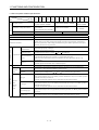
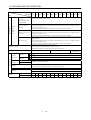
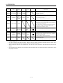
1. FUNCTIONS AND CONFIGURATION
Servo amplifier
10CL
MR-J2S-
20CL
40CL
60CL
70CL
100CL 200CL 350CL 500CL 700CL 10CL1 20CL1 40CL1
Item
Operation mode
Home position
ignorance
(Servo-on position as
home position)
Manual
home
position
return
mode
Dog type rear end
reference
Count type front end
reference
Dog cradle type
Position where servo-on (SON) is switched on is defined as home position.
Home position address may be set.
Home position return is made with respect to the rear end of a proximity dog.
Home position address may be set. Home position shift value may be set. Home position
return direction may be set.
Automatic at-dog home position return, Automatic stroke return function
Home position return is made with respect to the front end of a proximity dog.
Home position address may be set. Home position shift value may be set. Home position
return direction may be set.
Automatic at-dog home position return, Automatic stroke return function
Home position return is made with respect to the front end of a proximity dog by the first
Z-phase pulse.
Home position address may be set. Home position shift value may be set. Home position
return direction may be set.
Automatic at-dog home position return, Automatic stroke return function
Absolute position detection, backlash function
Overtravel prevention using external limit switch
Software stroke limit, override using external analog signal
Other functions
Structure
Environment
Ambient
temperature
Ambient
humidity
Self-cooled, open (IP00)
Operation
Storage
Force-cooling, open (IP00)
[ ] 0 to 55 (non-freezing)
[ ] 32 to 131 (non-freezing)
[ ]
20 to 65 (non-freezing)
[ ]
4 to 149 (non-freezing)
Operation
90%RH or less (non-condensing)
Storage
Ambient
Indoors (no direct sunlight)
Free from corrosive gas, flammable gas, oil mist, dust and dirt
Altitude
Max. 1000m (3280ft) above sea level
5.9 [m/s2] or less
Vibration
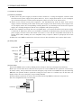
Weight
Self-cooled,
open (IP00)
19.4 [ft/s2] or less
[kg]
0.7
0.7
1.1
1.1
1.7
1.7
2.0
2.0
4.9
7.2
0.7
0.7
1.1
[lb]
1.5
1.5
2.4
2.4
3.75
3.75
4.4
4.4
10.8
15.87
1.5
1.5
2.4
1 - 10
1. FUNCTIONS AND CONFIGURATION
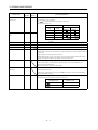
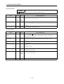
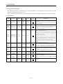
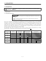
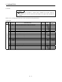
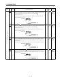
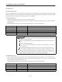
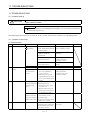
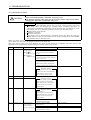
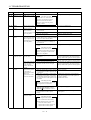
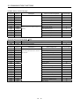
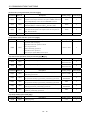
1.3 Function list
The following table lists the functions of this servo. For details of the functions, refer to the reference field.
Function
Description
Reference
Positioning by program operation
Operation is performed in accordance with the contents of any
program selected from among pre-created 16 programs.
Use the external input signal or communication function to choose
the program.
Section 4.2
Manual home position return
Dog type, count type, data setting type, stopper type, home
position ignorance, dog type rear end reference, count type front
end reference, dog cradle type
Section 4.4
Multidrop communication
Up to 32 axes of MR-J2S-CL are controllable simultaneously by
RS-422 communication.
Section 4.6.3
Chapter 15
High-resolution encoder
High-resolution encoder of 131072 pulses/rev is used as a servo
motor encoder.
Absolute position detection system
By merely setting the home position once, home position return
need not be done at each power on.
Section 4.5
Gain changing function
You can switch between gains during rotation and gains during
stop or use an external signal to change gains during operation.
Section 9.5
Adaptive vibration suppression control
Servo amplifier detects mechanical resonance and sets filter
characteristics automatically to suppress mechanical vibration.
Section 9.3
Low-pass filter
Suppresses high-frequency resonance which occurs as servo
system response is increased.
Section 9.4
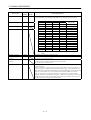
Machine analyzer function
Analyzes the frequency characteristic of the mechanical system by
simply connecting a servo configuration software-installed
personal computer and servo amplifier.
Machine simulation
Can simulate machine motions on a personal computer screen on
the basis of the machine analyzer results.
Gain search function
Personal computer changes gains automatically and searches for
overshoot-free gains in a short time.
Slight vibration suppression control
Vibration of 1 pulse at servo motor stop is suppressed.
Electronic gear
The electronic gear is used to make adjustment so that the servo
amplifier setting matches the machine moving distance. Also,
changing the electronic gear value allows the machine to be moved
at any multiplication ratio to the moving distance using the servo
amplifier.
Section 5.2.1
Auto tuning
Automatically adjusts the gain to optimum value if load applied to
the servo motor shaft varies. Higher in performance than MR-J2
series servo amplifier.
Chapter 8
S-pattern acceleration/deceleration time
Acceleration/deceleration can be made smoothly.
constant
Parameter No. 20
Section 4.2.1 (2) 2)
Section 5.2.3
Regenerative brake option
Used when the built-in regenerative brake resistor of the servo
amplifier does not have sufficient regenerative capability for the
regenerative power generated.
Section 14.1.1
Brake unit
Used when the regenerative brake option cannot provide enough
regenerative power.
Can be used with the MR-J2S-500CL MR-J2S-700CL.
Section 14.1.2
Return converter
Used when the regenerative brake option cannot provide enough
regenerative power.
Can be used with the MR-J2S-500CL MR-J2S-700CL.
Section 14.1.3
1 - 11
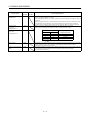
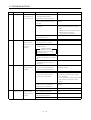
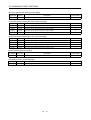
1. FUNCTIONS AND CONFIGURATION
Function
Description
Reference
Analog monitor
The servo status is output in terms of voltage in real time.
Section 5.2.4
Alarm history
By using the Servo configuration Software, the current alarm and
five past alarm numbers are stored and displayed.
Section 6.8
I/O signal selection (Device setting)
By using the Servo configuration Software, any devices can be
assigned to 9 input, 5 output and 1 I/O pins.
Section 6.6
Torque limit
Servo motor-torque is limited.
Parameter
2 limit value
Analog input
1 limit value
Section 3.2.5
Override (speed limit)
The servo motor speed is limited by analog input.
The ratio of override to the set speed can be changed between 0 to
200%.
Section 3.2.4
Status display
The servo status is displayed.
Section 7.2
Test operation mode
Jog, Positioning, Operation w/o motor, Forced output, Program
test
Section 6.7
Limit switch
The servo motor travel region can be limited using the forward
rotation stroke end (LSP)/reverse rotation stroke end (LSN).
Section 5.2.5
Software limit
The travel region is limited using parameters in terms of address.
The function similar to that of a limit switch is limited by
parameter.
Section 5.2.9
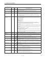
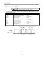
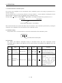
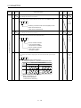
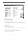
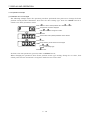
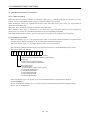
1.4 Model code definition
(1) Rating plate
MITSUBISHI
MODEL
AC
SERVO
AC SERVO
MR-J2S-60CL
POWER : 600W
POWER
INPUT : 3.2A 3PH 1PH200-230V 50Hz
3PH 1PH200-230V 60Hz
5.5A 1PH 230V 50/60Hz
OUTPUT : 170V 0-360Hz 3.6A
SERIAL : A5
TC3
AAAAG52
PASSED
Model
Capacity
Applicable power supply
Rated output current
Serial number
MITSUBISHI ELECTRIC CORPORATION
MADE IN JAPAN
1 - 12
1. FUNCTIONS AND CONFIGURATION
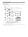
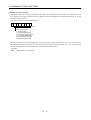
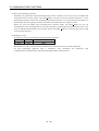
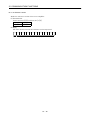
(2) Model
MR–J2S–
CL
MR–J2S–100CL or less
Series
MR–J2S–200CL 350CL
Power Supply
Symbol
Power supply
None
3-phase 200 to 230VAC
(Note2) 1-phase 230VAC
(Note1)
1-phase 100V to 120VAC
1
Rating plate
Note:1. Not supplied to the servo amplifier of
MR-J2S-60CL or more.
2. Not supplied to the servo amplifier of
MR-J2S-100CL or more.
Rating plate
MR-J2S-500CL
MR-J2S-700CL
Program compatibility operation function
Rated output
Rated
output [W]
100
200
400
600
750
Symbol
10
20
40
60
70
Symbol
Rated
output [W]
100
200
350
500
700
1000
2000
3500
5000
7000
Rating plate
Rating plate
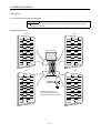
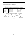
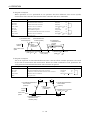
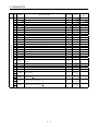
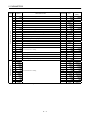
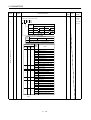
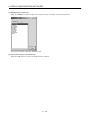
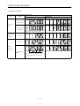
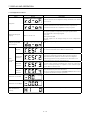
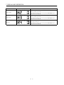
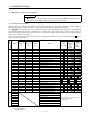
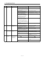
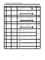
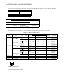
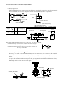
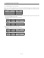
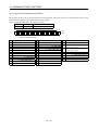
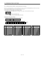
1.5 Combination with servo motor
The following table lists combinations of servo amplifiers and servo motors. The same combinations apply
to the models with electromagnetic brakes and the models with reduction gears.
Servo amplifier
MR-J2S-10CL (1)
HC-KFS
053
13
HC-MFS
053
MR-J2S-20CL (1)
23
23
MR-J2S-40CL (1)
43
43
Servo motors
HC-SFS
1000r/min
73
3000r/min
HC-RFS
13
43
52
53
102
103
73
72
81
MR-J2S-200CL
121
MR-J2S-350CL
201
301
152
202
352
MR-J2S-500CL
502
MR-J2S-700CL
702
153
203
103
353
HA-LFS
(Note)
1500r/min
2000r/min
(Note)
HC-LFS
MR-J2S-60CL
52
MR-J2S-100CL
102
MR-J2S-200CL
152
MR-J2S-350CL
202
MR-J2S-500CL
MR-J2S-700CL
(Note)502
601
701M
302
(Note)702
Note: Consult us since the servo amplifier to be used with any of these servo motors is optional.
1 - 13
153
203
353
Servo motors
(Note)
1000r/min
3000r/min
23
MR-J2S-100CL
Servo amplifier
HC-UFS
2000r/min
13
MR-J2S-60CL
MR-J2S-70CL
2000r/min
503
152
202
352
502
73
1. FUNCTIONS AND CONFIGURATION
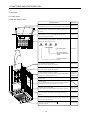
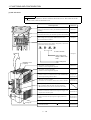
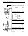
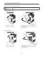
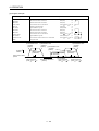
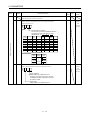
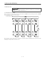
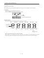
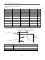
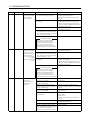
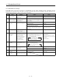
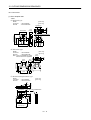
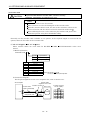
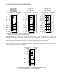
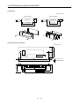
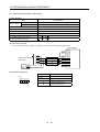
1.6 Structure
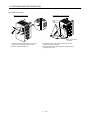
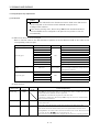
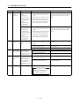
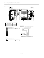
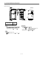
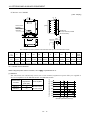
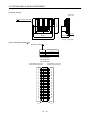
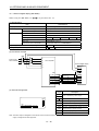
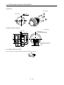
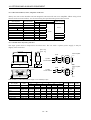
1.6.1 Part names
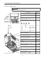
(1) MR-J2S-100CL or less
Name/Application
Reference
Battery holder
Contains the battery for absolute position data backup.
Section4.5
Battery connector (CON1)
Used to connect the battery for absolute position data
backup.
Section4.5
Display
The 5-digit, seven-segment LED shows the servo
status and alarm number.
Chapter7
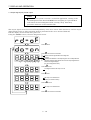
Operation section
Used to perform status display, diagnostic, alarm and
parameter setting operations.
MODE
UP
DOWN
SET
MODE
UP
DOWN
SET
Used to set data.
Chapter7
Used to change the
display or data in each
mode.
Used to change the
mode.
I/O signal connector (CN1A)
Used to connect digital I/O signals.
Section3.3
I/O signal connector (CN1B)
Used to connect digital I/O signals.
Section3.3
Communication connector (CN3)
Used to connect a command device (RS-422/RS-232C)
and output analog monitor data.
Name plate
Chapter6
Chapter15
Section14.1.4
Section1.4
Charge lamp
Lit to indicate that the main circuit is charged. While
this lamp is lit, do not reconnect the cables.
Encoder connector (CN2)
Connector for connection of the servo motor encoder.
Section3.3
Section14.1.4
Main circuit terminal block (TE1)
Used to connect the input power supply and servo
motor.
Section3.7.2
Control circuit terminal block (TE2)
Used to connect the control circuit power supply and
regenerative brake option.
Section3.7.2
Section14.1.1
Protective earth (PE) terminal (
Ground terminal.
1 - 14
)
Section3.10
1. FUNCTIONS AND CONFIGURATION
(2) MR-J2S-200CL MR-J2S-350CL
POINT
This servo amplifier is shown without the front cover. For removal of the
front cover, refer to Section 1.6.2.
MODE
UP
DOWN
SET
Name/Application
Reference
Battery holder
Contains the battery for absolute position data backup.
Section4.5
Battery connector (CON1)
Used to connect the battery for absolute position data
backup.
Section4.5
Display
The 5-digit, seven-segment LED shows the servo
status and alarm number.
Chapter7
Operation section
Used to perform status display, diagnostic, alarm and
parameter setting operations.
MODE
UP
DOWN
SET
Used to set data.
Chapter7
Used to change the
display or data in each
mode.
Used to change the
mode.
I/O signal connector (CN1A)
Used to connect digital I/O signals.
Section3.3
I/O signal connector (CN1B)
Used to connect digital I/O signals.
Section3.3
Communication connector (CN3)
Used to connect a command device (RS-422/RS232C)
and output analog monitor data.
Name plate
Chapter6
Chapter15
Section14.1.4
Section1.4
Charge lamp
Lit to indicate that the main circuit is charged. While
this lamp is lit, do not reconnect the cables.
Encoder connector (CN2)
Connector for connection of the servo motor encoder.
Main circuit terminal block (TE1)
Used to connect the input power supply and servo
motor.
Control circuit terminal block (TE2)
Used to connect the control circuit power supply and
regenerative brake option.
Cooling fan
Mounting hole (4 places)
Protective earth (PE) terminal (
Ground terminal.
1 - 15
)
Section3.3
Section14.1.4
Section3.7
Section3.7.2
Section14.1.1
Section3.10
1. FUNCTIONS AND CONFIGURATION
(3) MR-J2S-500CL
POINT
The servo amplifier is shown without the front cover. For removal of the
front cover, refer to Section 1.6.2.
Name/Application
Battery connector (CON1)
Used to connect the battery for absolute position data
backup.
Battery holder
Contains the battery for absolute position data backup.
Display
The 5-digit, seven-segment LED shows the servo
status and alarm number.
MODE
UP
DOWN
Reference
Section4.5
Section4.5
Chapter7
Operation section
Used to perform status display, diagnostic, alarm and
parameter setting operations.
SET
MODE
UP
DOWN SET
Used to set data.
Chapter7
Used to change the
display or data in each
mode.
Installation notch
(4 places)
Used to change the
mode.
I/O signal connector (CN1A)
Used to connect digital I/O signals.
Section3.3
I/O signal connector (CN1B)
Used to connect digital I/O signals.
Section3.3
Communication connector (CN3)
Used to connect a command device (RS-422/RS232C)
and output analog monitor data.
Chapter6
Chapter15
Section14.1.4
Encoder connector (CN2)
Connector for connection of the servo motor encoder.
Section3.3
Section14.1.4
Charge lamp
Lit to indicate that the main circuit is charged.
While this lamp is lit, do not reconnect the cables.
Control circuit terminal block (TE2)
Used to connect the control circuit power supply and
regenerative brake option.
Section3.7.2
Section14.1.4
Main circuit terminal block (TE1)
Used to connect the input power supply and servo
motor.
Section3.7.2
Section12.1
Section14.1.1
Name plate
Cooling fan
Protective earth (PE) terminal (
Ground terminal.
1 - 16
Section1.3
)
Section3.10
Section12.1
1. FUNCTIONS AND CONFIGURATION
(4) MR-J2S-700CL
POINT
The servo amplifier is shown without the front cover. For removal of the
front cover, refer to next page.
Name/Application
MODE
UP
DOWN
SET
Reference
Battery connector (CON1)
Used to connect the battery for absolute position data
backup.
Section4.5
Battery holder
Contains the battery for absolute position data backup.
Section4.5
Display
The 5-digit, seven-segment LED shows the servo
status and alarm number.
Chapter7
Operation section
Used to perform status display, diagnostic, alarm and
parameter setting operations.
MODE
UP
DOWN
SET
Used to set data.
Chapter7
Used to change the
display or data in each
mode.
Used to change the
mode.
I/O signal connector (CN1A)
Used to connect digital I/O signals.
Section3.3
I/O signal connector (CN1B)
Used to connect digital I/O signals.
Section3.3
Communication connector (CN3)
Used to connect a command device (RS-422/RS232C)
and output analog monitor data.
Chapter6
Chapter15
Section14.1.4
Charge lamp
Lit to indicate that the main circuit is charged.
While this lamp is lit, do not reconnect the cables.
Control circuit terminal block (TE2)
Used to connect the control circuit power supply.
Section3.7.2
Section14.1.4
Encoder connector (CN2)
Connector for connection of the servo motor encoder.
Section3.3
Section14.1.4
Section1.3
Name plate
Main circuit terminal block (TE1)
Used to connect the input power supply, regenerative
brake option and servo motor.
Cooling fan
Installation notch
(4 places)
Protective earth (PE) terminal (
Ground terminal.
1 - 17
)
Section3.7.2
Section12.1
Section14.1.1
Section3.10
Section12.1
1. FUNCTIONS AND CONFIGURATION
1.6.2 Removal and reinstallation of the front cover
To avoid the risk of an electric shock, do not open the front cover while power is
on.
CAUTION
(1) For MR-J2S-200CL or more
Reinstallation of the front cover
Removal of the front cover
1)
Front cover hook
(2 places)
2)
2)
Front cover
1)
Front cover socket
(2 places)
1) Hold down the removing knob.
2) Pull the front cover toward you.
1) Insert the front cover hooks into the front cover sockets of
the servo amplifier.
2) Press the front cover against the servo amplifier until the
removing knob clicks.
(2) For MR-J2S-500CL
Reinstallation of the front cover
Removal of the front cover
1)
Front cover hook
(2 places)
2)
2)
1)
Front cover
Front cover socket
(2 places)
1) Hold down the removing knob.
2) Pull the front cover toward you.
1) Insert the front cover hooks into the front cover sockets of
the servo amplifier.
2) Press the front cover against the servo amplifier until the
removing knob clicks.
1 - 18
1. FUNCTIONS AND CONFIGURATION
(3) For MR-J2S-700CL
Reinstallation of the front cover
Removal of the front cover
Front cover
hook
(2 places)
A)
B)
2)
2)
1)
A)
1)
Front cover socket
(2 places)
1) Push the removing knob A) or B), and put you
finger into the front hole of the front cover.
2) Pull the front cover toward you.
1) Insert the two front cover hooks at the bottom into the
sockets of the servo amplifier.
2) Press the front cover against the servo amplifier until the
removing knob clicks.
1 - 19
1. FUNCTIONS AND CONFIGURATION
1.7 Servo system with auxiliary equipment
WARNING
To prevent an electric shock, always connect the protective earth (PE) terminal
(terminal marked ) of the servo amplifier to the protective earth (PE) of the control
box.
(1) MR-J2S-100CL or less
(a) For 3-phase 200V to 230VAC or 1-phase 230VAC
(Note2)
3-phase 200V
to 230VAC power
supply or
1-phase 230VAC
power supply
Options and auxiliary equipment
Reference
Options and auxiliary equipment
Reference
No-fuse breaker
Section 14.2.2
Cables
Section 14.2.1
Magnetic contactor
Section 14.2.2
Manual pulse generator
Section 14.1.8
Chapter 6
External digital display
Section 14.1.7
Servo configuration software
Regenerative brake option
Section 14.1.1
Power factor improving reactor Section 14.2.3
No-fuse breaker
(NFB) or fuse
Command device
Servo amplifier
Junction terminal block
To CN1A
Manual pulse generator
Magnetic
contactor
(MC)
To CN1B
External digital display
Power
factor
improving
reactor
(FR-BAL)
To CN3
CHARGE
Personal
computer
To CN2
L1
L2
L3
U
V
Servo configuration
software
MRZJW3-SETUP151E
W
Protective earth (PE) terminal
(Note1)
Encoder cable
(Note1)
Power supply lead
Control circuit terminal block
D
L21
L11
P
Regenerative brake
option
Servo motor
C
Note: 1. The HC-SFS, HC-RFS, HC-UFS 2000r/min series have cannon connectors.
2. A 1-phase 230VAC power supply may be used with the servo amplifier of MR-J2S-70CL or less. Connect the power supply to
L1 and L2 terminals and leave L3 open.
1 - 20
1. FUNCTIONS AND CONFIGURATION
(b) For 1-phase 100V to 120VAC
1-phase 100V
to 120VAC
power supply
Options and auxiliary equipment
Options and auxiliary equipment
Reference
No-fuse breaker
Section 14.2.2
Cables
Section 14.2.1
Magnetic contactor
Section 14.2.2
Manual pulse generator
Section 14.1.8
Chapter 6
External digital display
Section 14.1.7
Servo configuration software
Regenerative brake option
No-fuse breaker
(NFB) or fuse
Reference
Section 14.1.1
Servo amplifier
Power factor improving reactor Section 14.2.3
Command device
Junction terminal block
To CN1A
Magnetic
contactor
(MC)
Manual pulse generator
To CN1B
External digital display
CHARGE
Power
factor
improving
reactor
(FR-BAL)
To CN3
Personal
computer
To CN2
L1
L2
U
V
Servo configuration
software
MRZJW3-SETUP151E
W
Protective earth (PE) terminal
(Note)
Encoder cable
(Note)
Power supply lead
Control circuit terminal block
D
L21
L11
P
Regenerative brake
option
Servo motor
C
Note: The HC-SFS, HC-RFS, HC-UFS 2000 r/min series have cannon connectors.
1 - 21
1. FUNCTIONS AND CONFIGURATION
(2) MR-J2S-200CL MR-J2S-350CL
3-phase 200V
to 230VAC
power supply
Options and auxiliary equipment
Reference
No-fuse breaker
Section 14.2.2
Cables
Section 14.2.1
Magnetic contactor
Section 14.2.2
Manual pulse generator
Section 14.1.8
Chapter 6
External digital display
Section 14.1.7
Servo configuration software
No-fuse
breaker
(NFB) or
fuse
Options and auxiliary equipment
Reference
Regenerative brake option
Power factor improving reactor Section 14.2.3
Section 14.1.1
Servo amplifier
Command device
Junction terminal
block
To CN1A
Magnetic
contactor
(MC)
Manual pulse
generator
To CN1B
Power
factor
improving
reactor
(FR-BAL)
To CN2
To CN3
Personal
computer
L11
L21
L1
L2
L3
External digital display
U V W
P
C
Regenerative brake option
1 - 22
Servo
configuration
software
MRZJW3SETUP151E
1. FUNCTIONS AND CONFIGURATION
(3) MR-J2S-500CL
3-phase 200V
to 230VAC
power supply
Options and auxiliary equipment
No-fuse
breaker
(NFB) or
fuse
Reference
Options and auxiliary equipment
Reference
No-fuse breaker
Section 14.2.2
Cables
Section 14.2.1
Magnetic contactor
Section 14.2.2
Manual pulse generator
Section 14.1.8
Chapter 6
External digital display
Section 14.1.7
Servo configuration software
Regenerative brake option
Section 14.1.1
Power factor improving reactor Section 14.2.3
Magnetic
contactor
(MC)
Command device
Power
factor
improving
reactor
(FR-BAL)
Servo amplifier
Junction terminal
block
To CN1A
Manual pulse
generator
L1
L2
L3
To CN1B
External digital display
C
P
Regenerative brake option
U
V
W
To CN3
To CN2
L11
L21
1 - 23
Personal
computer
Servo
configuration
software
MRZJW3SETUP151E
1. FUNCTIONS AND CONFIGURATION
(4) MR-J2S-700CL
Options and auxiliary equipment
3-phase 200V
to 230VAC
power supply
Reference
Options and auxiliary equipment
Reference
No-fuse breaker
Section 14.2.2
Cables
Section 14.2.1
Magnetic contactor
Section 14.2.2
Manual pulse generator
Section 14.1.8
Chapter 6
External digital display
Section 14.1.7
Servo configuration software
Regenerative brake option
Section 14.1.1
Power factor improving reactor Section 14.2.3
Command device
No-fuse
breaker
(NFB) or
fuse
Junction terminal
block
Servo amplifier
L11
To CN1A
L21
Manual pulse
generator
Magnetic
contactor
(MC)
To CN1B
External digital display
Power
factor
improving
reactor
(FR-BAL)
To CN3
Personal
computer
To CN2
L3
L2
L1
U
V
W
C
P
Regenerative brake option
1 - 24
Servo
configuration
software
MRZJW3SETUP151E
2. INSTALLATION
2. INSTALLATION
CAUTION
Stacking in excess of the limited number of products is not allowed.
Install the equipment to incombustibles. Installing them directly or close to
combustibles will led to a fire.
Install the equipment in a load-bearing place in accordance with this Instruction
Manual.
Do not get on or put heavy load on the equipment to prevent injury.
Use the equipment within the specified environmental condition range.
Provide an adequate protection to prevent screws, metallic detritus and other
conductive matter or oil and other combustible matter from entering the servo
amplifier.
Do not block the intake/exhaust ports of the servo amplifier. Otherwise, a fault may
occur.
Do not subject the servo amplifier to drop impact or shock loads as they are
precision equipment.
Do not install or operate a faulty servo amplifier.
When the product has been stored for an extended period of time, consult
Mitsubishi.
2.1 Environmental conditions
Environment
Ambient
temperature
Operation
Storage
Ambient
Operation
humidity
Storage
Conditions
[ ] 0 to 55 (non-freezing)
[ ] 32 to 131 (non-freezing)
[ ]
20 to 65 (non-freezing)
[ ]
4 to 149 (non-freezing)
90%RH or less (non-condensing)
Indoors (no direct sunlight)
Ambience
Free from corrosive gas, flammable gas, oil mist, dust and dirt
Altitude
Max. 1000m (3280 ft) above sea level
2
Vibration
[m/s ] 5.9 [m/s2] or less
[ft/s2] 19.4 [ft/s2] or less
2- 1
2. INSTALLATION
2.2 Installation direction and clearances
CAUTION
Do not hold the front cover to transport the controller. The controller may drop.
The equipment must be installed in the specified direction. Otherwise, a fault may
occur.
Leave specified clearances between the servo amplifier and control box inside
walls or other equipment.
(1) Installation of one servo amplifier
Control box
Control box
40mm
(1.6 in.)
or more
Servo amplifier
Wiring clearance
70mm
(2.8 in.)
Up
10mm
(0.4 in.)
or more
10mm
(0.4 in.)
or more
Down
40mm
(1.6 in.)
or more
2- 2
2. INSTALLATION
(2) Installation of two or more servo amplifiers
Leave a large clearance between the top of the servo amplifier and the internal surface of the control
box, and install a fan to prevent the internal temperature of the control box from exceeding the
environmental conditions.
Control box
10mm
(0.4 in.)
or more
100mm
(4.0 in.)
or more
30mm
(1.2 in.)
or more
30mm
(1.2 in.)
or more
40mm
(1.6 in.)
or more
(3) Others
When using heat generating equipment such as the regenerative brake option, install them with full
consideration of heat generation so that the servo amplifier is not affected.
Install the servo amplifier on a perpendicular wall in the correct vertical direction.
2.3 Keep out foreign materials
(1) When installing the unit in a control box, prevent drill chips and wire fragments from entering the
servo amplifier.
(2) Prevent oil, water, metallic dust, etc. from entering the servo amplifier through openings in the control
box or a fan installed on the ceiling.
(3) When installing the control box in a place where there are much toxic gas, dirt and dust, conduct an
air purge (force clean air into the control box from outside to make the internal pressure higher than
the external pressure) to prevent such materials from entering the control box.
2- 3
2. INSTALLATION
2.4 Cable stress
(1) The way of clamping the cable must be fully examined so that flexing stress and cable's own weight
stress are not applied to the cable connection.
(2) For use in any application where the servo motor moves, fix the cables (encoder, power supply, brake)
supplied with the servo motor, and flex the optional encoder cable or the power supply and brake
wiring cables. Use the optional encoder cable within the flexing life range. Use the power supply and
brake wiring cables within the flexing life of the cables.
(3) Avoid any probability that the cable sheath might be cut by sharp chips, rubbed by a machine corner
or stamped by workers or vehicles.
(4) The flexing lives of the cables are shown below. In actuality, provide a little allowance for these values.
For installation on a machine where the servo motor will move, the flexing radius should be made as
large as possible. Refer to Section 13.4 for the flexing life.
2- 4
3. SIGNALS AND WIRING
3. SIGNALS AND WIRING
WARNING
Any person who is involved in wiring should be fully competent to do the work.
Before starting wiring, switch power off, then wait for more than 10 minutes, and
after the charge lamp has gone off, make sure that the voltage is safe in the tester
or like. Otherwise, you may get an electric shock.
Ground the servo amplifier and the servo motor securely.
Do not attempt to wire the servo amplifier and servo motor until they have been
installed. Otherwise, you may get an electric shock.
The cables should not be damaged, stressed excessively, loaded heavily, or
pinched. Otherwise, you may get an electric shock.
Wire the equipment correctly and securely. Otherwise, the servo motor may
misoperate, resulting in injury.
Connect cables to correct terminals to prevent a burst, fault, etc.
Ensure that polarity ( , ) is correct. Otherwise, a burst, damage, etc. may occur.
The surge absorbing diode installed to the DC relay designed for control output
should be fitted in the specified direction. Otherwise, the signal is not output due to
a fault, disabling the forced stop (EMG) and other protective circuits.
Servo
amplifier
Servo amplifier
COM
(24VDC)
COM
(24VDC)
CAUTION
Control
output
signal
RA
Control output
signal
RA
Use a noise filter, etc. to minimize the influence of electromagnetic interference,
which may be given to electronic equipment used near the servo amplifier.
Do not install a power capacitor, surge suppressor or radio noise filter (FR-BIF
option) with the power line of the servo motor.
When using the regenerative brake resistor, switch power off with the alarm signal.
Otherwise, a transistor fault or the like may overheat the regenerative brake
resistor, causing a fire.
Do not modify the equipment.
POINT
CN1A, CN1B, CN2 and CN3 have the same shape. Wrong connection of
the connectors will lead to a failure. Connect them correctly.
3- 1
3. SIGNALS AND WIRING
3.1 Standard connection example
Servo amplifier
Proximity dog
(Note 3, 7) (Note 3, 7)
CN1A
CN1A
DOG 8
9 COM
Servo-on
SON
19
SG
10
18
Home position
return completion
(Note 2, 4)
ZP
RA5
10m (32.79ft.) or less
(Note 5)
Forward rotation stroke end
(Note 3, 7) (Note 3, 7)
CN1B
CN1B
LSP 16
3 VDD
Reverse rotation stroke end
LSN
17
Program input 1
PI1
8
Program input 2
PI2
9
Forward rotation start
ST1
Program No. selection 1
13 COM
(Note 2, 4)
4
OUT1
RA1
7
6
PED
RA2
DI0
5
18
ALM
RA3
Program No. selection 2
DI1
14
Reset
RST
15
19
RD
RA4
SG
10
P15R
11
VC
2
LG
1
Upper limit setting
(Note 8) Override
Upper limit setting
TLA
(Note 9) Analog torque limit
12
Program output 1
Movement
complete
Trouble (Note 6)
Ready
(Note 3, 7)
CN1B
6
LA
16
LAR
7
LB
17
LBR
5
LZ
15
LZR
Encoder A-phase pulse
(differential line driver)
Encoder B-phase pulse
(differential line driver)
Encoder Z-phase pulse
(differential line driver)
Plate SD
SD Plate
(Note 3, 7)
2m (6.56ft.) or less
CN3
4
3
MO1
10k
LG
A
14 MO2
(Note 11)
Servo Configuration
software
Personal
computer
13
(Note 10)
Communication cable
CN3
A
10k
LG
Plate SD
2m (6.56ft.) or less
(Note 1)
3- 2
(Note 10)
Monitor output
Max. 1mA
meter
Zero center
3. SIGNALS AND WIRING
Note: 1. To prevent an electric shock, always connect the protective earth (PE) terminal of the servo amplifier to the protective earth
(PE) of the control box.
2. Connect the diode in the correct direction. If it is connected reversely, the servo amplifier will be faulty and will not output
signals, disabling the emergency stop and other protective circuits.
3. CN1A, CN1B, CN2 and CN3 have the same shape. Wrong connection of the connectors will lead to a fault.
4. The sum of currents that flow in the external relays should be 80mA max. If it exceeds 80mA, supply interface power from
external.
5. When starting operation, always connect the forward/reverse rotation stroke end (LSN/LSP) with SG. (Normally closed
contacts)
6. Trouble (ALM) is connected with COM in normal alarm-free condition.
7. The pins with the same signal name are connected in the servo amplifier.
8. When using override (VC), make the override selection (OVR) device available.
9. When using analog torque limit (TLA), make the external torque limit selection (TL) devices available.
10. When connecting the personal computer together with monitor outputs 1, 2, use the maintenance junction card (MR-J2CN3TM).
(Refer to Section 14.1.6).
11. Use MRZJW3-SETUP 151E (Ver. E1 or more).
12. Connect to CN1A-10 when using the junction terminal block (MR-TB20).
3- 3
3. SIGNALS AND WIRING
3.2 Internal connection diagram of servo amplifier
This section gives the internal connection diagram where the signal assignment is in the initial status.
Servo amplifier
CN1B
VDD
3
COM
13
24VDC
CN1A
CN1A
COM
18
9
ZP
Approx. 4.7k
DOG
8
SON
19
SG
10, 20
Approx. 4.7k
CN1B
CN1B
DI0
5
4
OUT1
6
PED
18
ALM
19
RD
Approx. 4.7k
ST1
7
Approx. 4.7k
PI1
8
Approx. 4.7k
PI2
9
DI1
14
RST
15
LSP
16
LSN
17
6
LA
SG
10, 20
16
LAR
7
LB
17
LBR
5
LZ
15
LZR
14
OP
1
LG
Approx. 4.7k
Approx. 4.7k
Approx. 4.7k
CN1A
Approx. 4.7k
CN1A
OPC
11
PG
13
PP
3
NG
12
Approx. 100
Approx. 100
Approx. 1.2k
Approx. 1.2k
NP
2
SD
Casing
CN3
CN1B
4
MO1
14
MO2
2
RXD
12
TXD
VC
2
TLA
12
15VDC
P15R
11
LG
1
9
SDP
SD
Casing
19
SDN
CN1A
5
RDP
4
15
RDN
P15R
PE
3- 4
3. SIGNALS AND WIRING
3.3 I/O signals
3.3.1 Connectors and signal arrangements
POINT
The connector pin-outs shown above are viewed from the cable connector
wiring section side.
(1) Signal arrangement
CN1A
11
1
2
NP
4
P15R
CN1B
12
LG
OPC
VC
13
3
14
PP
5
4
OUT1
15
6
16
Servo amplifier
6
PED
17
7
8
18
8
DOG
ZP
PI1
10
9
20
COM
SG
19
10
SON
LG
3
4
3
VDD
LG
5
MD
MDR
9
10
2
LG
RXD
13
4
BAT
MO1
15
16
MR
DI1
5
DI0
16
LSP
7
ST1
18
ALM
9
20
PI2
13
COM
15
RST
17
LSN
19
RD
SG
1
11
12
14
7
14
P15R
CN3
6
8
TLA
SG
SG
1
LG
12
LG
CN2
2
11
1
2
18
P5
20
6
17
MRR
19
The connector frames are
connected with the PE (earth)
terminal inside the servo amplifier.
P5
LG
5
RDP
TXD
14
MO2
16
7
LG
13
LG
15
RDN
17
18
9
TRE
3- 5
3
8
10
P5
LG
11
12
SDP
19
20
P5
SDN
3. SIGNALS AND WIRING
3.3.2 Signal (devices) explanations
(1) I/O devices
POINT
The devices not indicated in the Connector Pin No. field of the I/O devices
can be assigned to the connector CN1A/CN1B using the Servo
Configuration software.
In the factory setting state, Forced stop (EMG) and Automatic/manual
selection (MD0) are not assigned to the pins but are preset to turn on
automatically.
(a) Pins whose devices can be changed
Refer to Section 3.6.2 for the I/O interfaces (symbols in the I/O Division field in the table) of the
corresponding connector pins.
Pin type
Connector pin No.
I/O division
CN1B-5
Program No. selection 1 (DI0)
CN1B-14
Program No. selection 2 (DI1)
CN1A-8
Proximity dog (DOG)
CN1B-15
Reset (RST)
CN1B-16
Input-only pins
DI-1
CN1B-17
I/O pin
Forward rotation stroke end (LSP)
Reverse rotation stroke end (LSN)
CN1B-7
Forward rotation start (ST1)
CN1B-8
Program input 1 (PI1)
CN1B-9
Program input 2 (PI2)
CN1A-19
Output-only pins
Device in initial status
DI-1 or DO-1
Servo-on (SON)
You can assign an I/O device using the Servo
Configuration software.
CN1B-4
Program output 1 (OUT1)
CN1B-6
Movement complete (PED)
CN1B-18
DO-1
Trouble (ALM)
CN1B-19
Ready (RD)
CN1A-18
Home position return completion(ZP)
(b) Input devices
Device name
Devices
symbol
Connector
pin No.
Functions/Applications
Forced stop
EMG
Turn EMG on to bring the motor to an Forced stop state, in which the servo is
switched off and the dynamic brake is operated.
Turn EMG off in the Forced stop state to reset that state.
In the factory setting state, Forced stop (EMG) is preset to turn on automatically.
(Refer to Section 6.6 (2) (c).)
Servo-on
SON
CN1B-19
Turn SON on to power on the base circuit and make the servo amplifier ready to
operate (servo-on).
Turn it off to shut off the base circuit and coast the servo motor (servo off).
Reset
RES
CN1B-15
Turn RES on for more than 50ms to reset the alarm.
Some alarms cannot be deactivated by the reset signal. Refer to Section 11.2.1.
Turning RES on in an alarm-free status shuts off the base circuit. The base circuit
is not shut off when " 1
" is set in parameter No. 55.
Since this device is not designed for stopping. Do not switch it on during operation.
3- 6
3. SIGNALS AND WIRING
Device name
Forward rotation
stroke end
Devices Connector
symbol
pin No.
LSP
Functions/Applications
CN1B-16 To start operation, turn LSP/LSN on. Turn it off to bring the motor to a sudden
stop and make it servo-locked.
Set "
1" in parameter No. 22 to make a slow stop.
(Refer to Section 5.2.5.)
(Note) Input signals
LSP
Reverse rotation stroke
end
LSN
CN1B-17
LSN
1
1
0
1
1
0
0
0
Operation
CCW
direction
CW
direction
Note. 0: OFF
1: ON
Program input1
PI1
CN1B-8 Turn PI1 on to resume the step stopped by the SYNC (1) command in the program.
Program input2
PI2
CN1B-9 Turn PI2 on to resume the step stopped by the SYNC (2) command in the program.
Program input3
PI3
Turn PI3 on to resume the step stopped by the SYNC (3) command in the program.
Forward rotation start
ST1
CN1B-7 1. In program operation mode
When ST1 is turned on, the operation of the program selected with DI0 to DI3 is
executed.
2. Jog operation in manual operation mode
While ST1 is kept on, the servo motor rotates in the forward rotation direction.
Forward rotation indicates an address increasing direction.
Reverse rotation start
ST2
While ST2 is kept on in jog operation of the manual operation mode, the servo
motor rotates in the reverse rotation direction. Reverse rotation indicates an
address decreasing direction.
ST2 is invalid in any other operation mode.
Automatic/manual
selection
MD0
Turn MD0 on to select the program operation mode, or turn it off to select the
manual operation mode.
In the factory setting state, Forced stop (EMG) is preset to turn on automatically.
(Refer to Section 6.6 (2) (c).)
Proximity dog
DOG
CN1A-8 Turn DOG on to bring, the proximity dog signal is detected. The polarity of dog
detection input can be changed with the parameter.
Parameter No.8
0
(initial value)
1
3- 7
Polarity of proximity dog
detection input
OFF
ON
3. SIGNALS AND WIRING
Device name
Devices Connector
symbol
pin No.
Functions/Applications
Program No. selection 1
DI0
CN1B-5 Select the program number from among those combined by DI0, DI1, DI2 and DI3
to start operation on the leading edge of ST1 in the program operation mode.
Program No. selection 2
DI1
CN1B-14
Program No. selection 3
DI2
Program No. selection 4
DI3
Input signal (Note)
Override selection
External torque limit
selection
Internal torque limit
selection
Proportion control
OVR
TL
TL2
PC
DI3
DI2
DI1
DI0
0
0
0
0
0
0
0
0
1
1
1
1
1
1
1
1
0
0
0
0
1
1
1
1
0
0
0
0
1
1
1
1
0
0
1
1
0
0
1
1
0
0
1
1
0
0
1
1
0
1
0
1
0
1
0
1
0
1
0
1
0
1
0
1
Program No.
1
2
3
4
5
6
7
8
9
10
11
12
13
14
15
16
Note. 0: OFF
1: ON
Turn OVR on to make override (VC) valid.
Turn TL on to make analog torque limit (TLA) valid.
For details, refer to Section 3.4.4.
Turn TL2 off to make parameter No.28 (Internal torque limit 1) valid, or turn it on
to make parameter No.29 (Internal torque limit 2) valid.
For detailes, refer to Section 3.4.4.
Turn PC on to bring the speed amplifier from the proportional integral type to the
proportional type.
If the servo motor at a stop is rotated even one pulse due to any external factor, it
generates torque to compensate for a position shift. In such a case where the axis
will be locked mechanically after Movement complete (PED) has turned off, turning
Proportion control (PC) on as soon as Movement complete (PED) turns off can
suppress unnecessary torque that attempts to compensate for a position shift.
When the shaft is to be locked for a long time, switch on the proportion control (PC)
and External torque limit selection (TL) at the same time to make the torque less
than the rated by the analog torque limit (TLA).
3- 8
3. SIGNALS AND WIRING
Device name
Temporary
stop/Restart
Manual pulse
generator
multiplication 1
Manual pulse
generator
multiplication 2
Devices Connector
Functions/Applications
symbol
pin No.
STP
Turn STP on during program operation to make a temporary stop.
Turn it on again to make a restart.
If any of Program inputs 1 to 3 (PI1 to PI3) is turned on during a temporary stop, it
is ignored.
When the program mode is switched to the manual mode during a temporary stop,
the remaining moving distance is erased. During home position return and jog
operation, the temporary stop/restart input is ignored. Refer to Section 4.2.6, (3).
TP0
Used to select the multiplication factor of the manual pulse generator.
When it is not selected, the parameter No.1 setting is made valid.
TP1
Gain switch
CDP
Current position latch
input
LPS
Manual pulse generator
(Note) Input signal
multiplication factor
TP1
TP0
0
0
Parameter No.1 setting
0
1
1 time
1
0
10 times
1
1
100 times
Note: 0: OFF
1: ON
Turn CDP on to change the load inertia moment ratio into parameter No. 64 (load
inertia moment ratio to servo motor 2) and the gain values into the values
multiplied by parameter No. 65 to 67.
Turn LPS on during execution of the LPOS command to latch the current position
on its leading edge. The latched current position can be read using the
communication command.
3- 9
3. SIGNALS AND WIRING
(c) Output devices
Device name
Trouble
Ready
Movement complete
Home position return
completion
Electromagnetic brake
interlock
Position range
Warning
Battery warning
Limiting torque
Temporary stop
Program output 1
Devices Connector
Functions/Applications
symbol
pin No.
ALM
CN1B-18 ALM turns off when power is switched off or the protective circuit is activated to
shut off the base circuit.
Without alarm occurring, ALM turns on within 1s after power-on.
RD
CN1B-19 RD turns on when the servo is switched on and the servo amplifier is ready to
operate.
PED
CN1B-6 PED turns on when the droop pulse value is within the movement complete output
range and the command remaining distance is "0". (Refer to Section 3.4.2.)
The movement complete output range can be changed with parameter No. 6.
INP turns on at servo-on.
When a home position return is not completed, PED is off in a servo-off status.
ZP
CN1A-18 ZP turns on at completion of a home position return.
In the absolute position system, ZP turns on when the servo amplifier is ready to
operate, but turns off if:
1) SON is turned off.
2) EMG is turned off.
3) RES is turned on.
4) Alarm occurs;
5) Limit switch opens;
6) Home position set has not been made after the purchase of the product;
7) Home position set has not been made after the occurrence of absolute position
erasure (AL. 25) or absolute position counter warning
(AL. E3);
8) Home position set has not been made after the setting of the electronic gear value;
9) Home position set has not been made after the absolute position system was made
valid; or
10) The ST1 coordinate system ("000 " in parameter No.1) has been changed.
11) Software limit is valid.
12) Home position return completion.
13) Home position set has not been made after home position return position data
(parameter No. 42) setting.
If the status is not any of 1) to 13) and the home position setting has already been
completed at least once, home position return completion (ZP) is placed in the same
output status as ready (RD).
MBR
MBR turns off when the servo is switched off or an alarm occurs.
When an alarm occurs, they are turned off independently of the base circuit status.
POT
Position range (POT) is on when the current position is within the range set in
parameters No. 50 to 53. If the current position is within the set range, the device
is off when a home position return is not yet complete or while the base circuit is off
(during servo off, alarm occurrence or alarm reset).
WNG
When warning has occurred, WNG turns on.
When there is no warning, WNG turns off within 1s after power-on.
BWNG
BWNG turns on when battery cable breakage warning (AL. 92) or battery warning
(AL. 9F) has occurred.
When there is no battery warning, BWNG turns off within 1s after power-on.
TLC
TLC-SG are connected when the torque generated reaches the value set to the
internal torque limit 1 (parameter No. 28), internal torque limit 1 (parameter No.
29) or analog torque limit (TLA). They are disconnected when the servo-on (SON)
switches off.
PUS
PUS turns on when deceleration to a stop is started by Temporary stop/restart
(STP). PUS turns off when Temporary stop/restart (STP) is enabled again to
resume operation.
CN1B-4 OUT1 turns on when the OUTON (1) command in the program is given. OUT1
OUT1
turns off when the OUTOF command is given.
The time to turn it off can be set in parameter No. 74.
Program output 2
OUT2
OUT2 turns on when the OUTON (2) command in the program is given. OUT2
turns off when the OUTOF command is given.
The time to turn it off can be set in parameter No. 75.
Program output 3
OUT3
OUT3 turns on when the OUTON (3) command in the program is given. OUT3
turns off when the OUTOF command is given.
The time to turn it off can be set in parameter No. 76.
3 - 10
3. SIGNALS AND WIRING
(2) Input signal
For the input interfaces (symbols in I/O column in the table), refer to Section 3.6.2.
Signal
Manual pulse
generator
Override
Analog torque limit
Signal
symbol
PP
PG
Connector
pin No.
I/O
division
CN1A-3 Used to connect the manual pulse generator (MR-HDP01).
CN1A-13 For details, refer to Section 14.1.8.
NP
CN1A-2
NG
CN1A-12
VC
CN1B-2
TLA
Functions/Applications
10 to 10V is applied to across VC-LG to limit the servo motor speed.
Apply 10[V] for 0[%] override, 0[V] for 100[%], or 10[V] for 200[%].
Analog
input
CN1B-12 To use this signal, set any of servo configuration software to make the
external torque limit selection (TL0) available.
When the analog torque limit (TLA) is valid, torque is limited in the full Analog
servo motor output torque range. Apply 0 to 10VDC across TLA-LG.
input
Connect the positive terminal of the power supply to TLA. Maximum
torque is generated at 10V. (Refer to in Section 3.4.4.) Resolution:10bits
(3) Output signal
For the output interfaces (symbols in I/O column in the table), refer to Section 3.6.2.
Signal
Encoder Z-phase pulse
(open collector)
Signal
symbol
OP
Connector
pin No.
Functions/Applications
CN1A-14 Outputs the zero-point signal of the encoder. One pulse is output per
servo motor revolution. OP and LG are connected when the zero-point
position is reached. (Negative logic)
The minimum pulse width is about 400 s. For home position return
using this pulse, set the creep speed to 100r/min. or less.
I/O
division
DO-2
Encoder A-phase pulse
(differential line driver)
LA
LAR
Encoder B-phase pulse
(differential line driver)
LB
LBR
CN1A-6 Outputs pulses per servo motor revolution set in parameter No. 27 in the
CN1A-16 differential line driver system. In CCW rotation of the servo motor, the
CN1A-7 encoder B-phase pulse lags the encoder A-phase pulse by a phase angle
CN1A-17 of /2.
The relationships between rotation direction and phase difference of the
A- and B-phase pulses can be changed using parameter No. 58.
Encoder Z-phase pulse
(differential line driver)
LZ
LZR
CN1A-5 The same signal as OP is output in the differential line driver system.
CN1A-15
Analog monitor 1
MO1
CN3-4
Used to output the data set in parameter No.17 to across MO1-LG in
terms of voltage. Resolution 10 bits
Analog
output
Analog monitor 2
MO2
CN3-14 Used to output the data set in parameter No.17 to across MO2-LG in
terms of voltage. Resolution 10 bits
Analog
output
3 - 11
DO-2
DO-2
DO-2
3. SIGNALS AND WIRING
(4) Communication
POINT
Refer to Chapter 15 for the communication function.
Signal
Signal
symbol
Connector
pin No.
Functions/Applications
RS-422 I/F
SDP
SDN
RDP
RDN
CN3-9 RS-422 and RS-232C functions cannot be used together.
CN3-19 Choose either one in parameter No. 16.
CN3-5
CN3-15
RS-422 termination
TRE
CN3-10 Termination resistor connection terminal of RS-422 interface.
When the servo amplifier is the termination axis, connect this terminal to RDN
(CN3-15).
RS-232C I/F
TXD
RXD
CN3-2 RS-422 and RS-232C functions cannot be used together.
CN3-12 Choose either one in parameter No. 16.
(5) Power supply
Signal
Signal
symbol
Connector
pin No.
Functions/Applications
I/F internal power
supply
VDD
CN1B-3 Used to output 24V 10% to across VDD-SG.
When using this power supply for digital interface, connect it with COM.
Permissible current : 80mA
Digital I/F power
supply input
COM
CN1A-9 Used to input 24VDC (200mA or more) for input interface.
CN1B-13 Connect the positive ( ) terminal of the 24VDC external power supply.
24VDC 10%
Open collector power
input
OPC
CN1A-11 When you use a manual pulse generator , supply this terminal with the positive ( )
power of 24VDC.
Digital I/F common
15VDC power supply
SG
P15R
Control common
LG
Shield
SD
CN1A-10 Common terminal for input signals such as SON and EMG. Pins are connected
20 internally.
CN1B-10 Separated from LG.
20
CN1A-4 Outputs 15VDC to across P15R-LG. Available as power for VC and VLA.
CN1B-11 Permissible current: 30mA
CN1A-1 Common terminal for TLA, VC, OP, MO1, MO2 and P15R.
CN1B-1 Pins are connected internally.
CN3-1,
11
3,
13
Plate
Connect the external conductor of the shield cable.
3 - 12
3. SIGNALS AND WIRING
3.4 Detailed description of signals (devices)
3.4.1 Forward rotation start Reverse rotation start Temporary stop/Restart
(1) A forward rotation start (ST1) or a reverse rotation start (ST2) should make the sequence which can
be used after the main circuit has been established. These signals are invalid if it is switched on before
the main circuit is established.
Normally, it is interlocked with the ready signal (RD).
(2) A start in the servo amplifier is made when the external start signal changes from OFF to ON. The
delay time of the servo amplifier's internal processing is max. 3ms. The delay time of other signals is
max. 10ms.
3ms or less
3ms or less
Servo motor speed
10ms
or less
Forward rotation start (ST1)
or reverse rotation start (ST2)
Temporary stop/Restart (STP)
5ms or more
(3) When a programmable controller is used, the ON time of the start/stop signal should be 5ms or longer
to prevent a malfunction.
(4) During operation, the forward rotation start (ST1) or reverse rotation start (ST2) is not accepted. The
next operation should always be started after the Movement complete (PED) is output.
3 - 13
3. SIGNALS AND WIRING
3.4.2 Movement complete
POINT
If servo-on occurs after a stop made by servo-off, alarm occurrence or
Forced stop (EMG) ON during automatic operation, Movement complete
(PED), turn on. To make a start again, confirm the program No. being
specified, and turn on Forward rotation start (ST1).
The following timing charts show the output timing relationships between the position command
generated in the servo amplifier and the Movement complete (PED). This timing can be changed using
parameter No. 6 (Movement complete output range). Turn PED on to bring in the servo-on status.
Forward rotation start (ST1)
or reverse rotation start (ST2)
ON
OFF
3ms or less
Position command
Servo motor speed
Position command and
servo motor speed
Movement complete range
ON
Movement complete (PED)
OFF
When parameter No. 6 is small
Forward rotation start (ST1) ON
or reverse rotation start (ST2) OFF
3ms or less
Position command
Servo motor speed
Position command and
servo motor speed
Movement complete range
ON
Movement complete (PED)
OFF
When parameter No. 6 is large
3 - 14
3. SIGNALS AND WIRING
3.4.3 Override
POINT
When using the override (VC), make the override selection (OVR) device
available.
The override (VC) may be used to change the servo motor speed. The following table lists the signals and
parameter related to the override:
Item
Name
Analog input signal
Override (VC)
Contact input signal
Override selection (OVR)
Parameter
No.25 override offset
Remarks
Servo Configuration Software setting required.
999 to 999mV
Ratio of actual speed to
preset speed
(1) Override (VC)
By applying a voltage ( 10 to 10V) to the override (VC) terminal, change values can be set from
outside consecutively. The following graph shows the relationship between the input voltage and the
ratio of actual speed to preset speed.
Servo amplifier
[%]
200
Override selection (OVR)
100
Override (VC)
10 to 10V
0
10
0
OVR
SG
VC
LG
SD
10 [V]
Override (VC) application voltage
(2) Override selection (OVR)
Used to make the override (VC) valid or invalid.
Override
Servo amplifier
Motor
Override selection
(OVR)
Override (VC)
10 to 10V
Using the override selection (OVR), choose a change value as follows:
External input signal
Speed change value
OVR
0
No change
1
Override (VC) setting is made valid.
Note. 0 : OFF
1 : ON
(3) Override offset (parameter No.25)
Using parameter No.25, the offset voltage can be set relative to the input voltage for the override (VC).
The setting is between 999 to 999mV.
3 - 15
3. SIGNALS AND WIRING
3.4.4 Torque limit
POINT
To use the torque limit, make the external torque limit selection (TL) and
internal torque limit selection (TL2) available.
The following table lists the signals and parameters related to the torque limit:
Item
Name
Analog input signal
Remarks
Analog torque limit (TLA)
External torque limit selection (TL)
Internal torque limit selection (TL2)
Limiting torque (TLC)
No.28 (internal torque limit 1)
No.29 (internal torque limit 2)
No.26 (torque limit offset)
Contact input signals
Contact output signal
Parameters
Servo Configuration
required.
Software
setting
0 to 100%
0 to 100%
999 to 999mV
Selection of the rotation direction in which
torque limit is executed
No.59 (function selection 2)
The torque limit is available in two types: internal torque limit set in parameters and analog torque limit
(TLA) using analog input signal. This function limits torque on the assumption that the maximum torque
of the servo motor is 100%.
(1) Internal torque limits 1, 2
Use parameter No.28 and 29 to set the internal torque limit values. The following graph shows the
torque relative to the setting.
Torque
Max. torque
0
0
100
Torque limit value [%]
Torque limit value [%]
(2) Analog torque limit (TLA)
By applying a voltage (0 to 10V) to the analog torque limit (TLA) terminal, limit values can be set from
outside consecutively. The following graph shows the relationship between input voltage and limit
value.
Depending on the servo amplifier, the limit value has about 5% variations to the input voltage. As this
may not cause torque to be limited sufficiently at less than 0.05V, use this function at the voltage of
0.05V or more.
Refer to the following diagram when using the 15V power output (P15R) of the servo amplifier:
Servo amplifier
100
TL
SG
P15R
5%
2k
0
0 0.05
10
TLA application voltage [V]
TLA Application Voltage vs.
Torque Limit Value
2k
TLA
LG
Japan Resistor RRS10
or equivalent
SD
Connection Example
3 - 16
3. SIGNALS AND WIRING
(3) External torque limit selection (TL), internal torque limit selection (TL2)
To use the external torque limit selection (TL) and internal torque limit selection (TL2), make them
available using the Servo Configuration Software (refer to Chapter 6).
These input signals may be used to choose the torque limit values made valid.
(Note) External input signals
TL2
TL
0
0
0
1
1
0
1
1
Torque limit value made valid
Internal torque limit value 1 (parameter No. 28)
TLA Parameter No. 28: Parameter No. 28
TLA Parameter No. 28: TLA
Parameter No. 29 Parameter No. 28: Parameter No. 28
Parameter No. 29 Parameter No. 28: Parameter No. 29
TLA Parameter No. 76: Parameter No. 29
TLA Parameter No. 29: TLA
Note.0: OFF
1: ON
(4) External torque limit offset (parameter No.26)
Using parameter No.26, the offset voltage can be set relative to the input voltage of the analog torque
limit (TLA). The setting is between 999 to 999mV.
(5) Selection of rotation direction for torque limit execution (parameter No.59)
Using parameter No.59, the rotation direction for torque limit execution can be selected.
Rotation direction for torque limit execution
Parameter No.59 setting
0
CCW direction
CW direction
(initial value)
1
2
For example, when “ 1
but not in CW direction.
” is set in parameter No.59, torque limit is executed in the CCW direction
CCW rotation: Torque limit is executed.
CW rotation: Torque limit is not executed.
3 - 17
3. SIGNALS AND WIRING
3.5 Alarm occurrence timing chart
CAUTION
When an alarm has occurred, remove its cause, make sure that the operation
signal is not being input, ensure safety, and reset the alarm before restarting
operation.
When an alarm occurs in the servo amplifier, the base circuit is shut off and the servo motor is coated to a
stop. Switch off the main circuit power supply in the external sequence. To reset the alarm, switch the
control circuit power supply from off to on, press the "SET" button on the current alarm screen, or turn
the reset (RES) from off to on. However, the alarm cannot be reset unless its cause is removed.
(Note)
Main circuit
control circuit
power supply
ON
OFF
ON
Base circuit
OFF
Dynamic brake Valid
Invalid
Servo-on
(SON)
Ready
(RD)
Trouble
(ALM)
Reset
(RES)
ON
OFF
ON
OFF
ON
OFF
ON
OFF
Power off
Brake operation
Power on
Brake operation
1s
Alarm occurs.
50ms or more
60ms or more
Remove cause of trouble.
Note. Switch off the main circuit power as soon as an alarm occurs.
(1) Overcurrent, overload 1 or overload 2
If operation is repeated by switching control circuit power off, then on to reset the overcurrent
(AL.32), overload 1 (AL.50) or overload 2 (AL.51) alarm after its occurrence, without removing
its cause, the servo amplifier and servo motor may become faulty due to temperature rise.
Securely remove the cause of the alarm and also allow about 30 minutes for cooling before
resuming operation.
(2) Regenerative alarm
If operation is repeated by switching control circuit power off, then on to reset the regenerative
(AL.30) alarm after its occurrence, the external regenerative brake resistor will generate heat,
resulting in an accident.
(3) Instantaneous power failure
Undervoltage (AL.10) occurs if power is restored after a 60ms or longer power failure of the
control power supply or after a drop of the bus voltage to or below 200VDC. If the power failure
persists further, the control power switches off. When the power failure is reset in this state, the
alarm is reset and the servo motor will start suddenly if the servo-on (SON) is on. To prevent
hazard, make up a sequence which will switch off the servo-on (SON) if an alarm occurs.
(4) Incremental system
When an alarm occurs, the home position is lost. When resuming operation after deactivating
the alarm, make a home position return.
3 - 18
3. SIGNALS AND WIRING
3.6 Interfaces
3.6.1 Common line
The following diagram shows the power supply and its common line.
CN1A
CN1B
CN1A
CN1B
24VDC
VDD
ALM,etc
COM
DO-1
SON,etc.
Dl-1
RA
SG
OPC
Manual pulse generator
MR-HDP01
5V
PP(NP)
A(B)
SG
0V
SG
<Isolated>
5V
OP
LG
15VDC 10% 30mA
P15R
LA,etc
Differential line driver
output
35mA or less
LAR,etc
LG
SD
TLA
VC,
etc.
Analog input
( 10V/max. current)
MO1
MO2
LG
CN3
Analog monitor
LG
SD
Single-phase
100 to 200VAC
RDP
RDN
SDP
TXD L1
TXD L2
RXD
RXD E
LG
SDN
LG
SD
CN2
MR
Servo motor
MRR
SM
SD
Ground
3 - 19
Servo motor encoder
3. SIGNALS AND WIRING
3.6.2 Detailed description of the interfaces
This section gives the details of the I/O signal interfaces (refer to I/O Division in the table) indicated in
Sections 3.3.2. Refer to this section and connect the interfaces with the external equipment.
(1) Digital input interface DI-1
Give a signal with a relay or open collector transistor. Source input is also possible. Refer to (6) in this
section.
For use of internal power supply
For use of external power supply
Servo amplifier
Do not connect
VDD-COM.
24VDC
VDD
Servo amplifier
R: Approx. 4.7
COM
24VDC
VDD
24VDC
200mA or more COM
(Note)
For a transistor
R: Approx. 4.7
SON, etc.
Approx. 5mA
SON, etc.
Switch
TR
SG
Switch
V CES 1.0V
I CEO 100 A
SG
Note: This also applies to the use of the external power supply.
(2) Digital output interface DO-1
A lamp, relay or photocoupler can be driven. Provide a diode (D) for an inductive load, or an inrush
current suppressing resister (R) for a lamp load. (Permissible current: 40mA or less, inrush current:
100mA or less)
(a) Inductive load
For use of internal power supply
For use of external power supply
Servo amplifier
24VDC
VDD
Do not connect
VDD-COM.
Servo amplifier
24VDC
VDD
COM
COM
Load
ALM, etc.
Load
24VDC
10%
ALM, etc.
SG
If the diode is not
connected as shown,
the servo amplifier
will be damaged.
SG
If the diode is not
connected as shown,
the servo amplifier
will be damaged.
3 - 20
3. SIGNALS AND WIRING
(b) Lamp load
For use of internal power supply
For use of external power supply
Servo amplifier
24VDC
Servo amplifier
VDD
24VDC
Do not connect
VDD-COM.
VDD
COM
COM
R
R
ALM, etc.
24VDC
10%
ALM, etc.
SG
SG
(3) Encoder pulse output DO-2
(a) Open collector system
Interface
Max. output current : 35mA
Servo amplifier
Servo amplifier
OP
OP
LG
LG
SD
SD
5 to 24VDC
Photocoupler
(b) Differential line driver system
1) Interface
Max. output current: 35mA
Servo amplifier
Servo amplifier
LA
(LB, LZ)
Am26LS32 or equivalent
LA
(LB, LZ)
100
150
LAR
(LBR, LZR)
LAR
(LBR, LZR)
LG
SD
SD
2) Output pulse
Servo motor CCW rotation
LA
LAR
T
LB
LBR
/2
LZ signal varies 3/8T on its leading edge.
LZ
LZR
400 s or more
OP
3 - 21
High-speed photocoupler
3. SIGNALS AND WIRING
(4) Analog input
Input impedance 10 to 12k
Servo amplifier
15VDC
P15R
Upper limit setting 2k
VC‚ etc
2k
LG
Approx.
10k
SD
(5) Analog output
Output voltage 10V
Max.1mA
Max. output current
Resolution : 10bits
Servo amplifier
MO1
(MO2)
LG
10k
Reading in one or
A
both directions
1mA meter
SD
(6) Source input interface
When using the input interface of source type, all Dl-1 input signals are of source type. Source output
cannot be provided.
For use of internal power supply
For use of external power supply
Servo amplifier
Servo amplifier
SG
COM
(Note)
For a transistor
Approx. 5mA
SG
R: Approx. 4.7
COM
SON,
etc.
Switch
Switch
SON,etc.
24VDC
TR
VDD
24VDC
200mA or more
VCES 1.0V
ICEO 100 A
Note: This also applies to the use of the external power supply.
3 - 22
R: Approx. 4.7
3. SIGNALS AND WIRING
3.7 Input power supply circuit
CAUTION
When the servo amplifier has become faulty, switch power off on the servo
amplifier power side. Continuous flow of a large current may cause a fire.
Use the trouble signal to switch power off. Otherwise, a regenerative brake
transistor fault or the like may overheat the regenerative brake resistor, causing a
fire.
3.7.1 Connection example
Wire the power supply and main circuit as shown below so that the servo-on (SON) turns off as soon as
alarm occurrence is detected and power is shut off.
A no-fuse breaker (NFB) must be used with the input cables of the power supply.
(1) For 3-phase 200 to 230VAC power supply
Forced
RA stop
OFF
ON
MC
MC
SK
NFB
MC
L1
3-phase
200 to 230 VAC
Servo amplifier
L2
L3
L11
L21
EMG
Forced stop
Servo-on
SON
SG
VDD
COM
ALM
3 - 23
RA
Trouble
3. SIGNALS AND WIRING
(2) For 1-phase 100 to 120VAC or 1-phase 230VAC power supply
Forced
RA stop
OFF
ON
MC
MC
SK
Power supply
1-phase 100 to
120VAC or
1-phase 230VAC
NFB
MC
L1
Servo amplifier
L2
L3 (Note)
L11
L21
EMG
Forced stop
Servo-on
SON
SG
VDD
COM
ALM
Note : Not provided for 1-phase 100 to 120VAC.
3 - 24
RA
Trouble
3. SIGNALS AND WIRING
3.7.2 Terminals
The positions and signal arrangements of the terminal blocks change with the capacity of the servo
amplifier. Refer to Section 12.1.
Symbol
Connection Target
(Application)
Description
Supply L1, L2 and L3 with the following power:
For 1-phase 230VAC, connect the power supply to L1/L2 and leave L3 open.
Power supply
L1, L2, L3
Main circuit power supply
Servo amplifier MR-J2S-10CL MR-J2S-100CL MR-J2S-10CL1
to 70CL
to 700CL
to 40CL1
3-phase 200 to 230VAC,
50/60Hz
1-phase 230VAC,
50/60Hz
L1
L1
L2 L3
L2
1-phase 100 to 120VAC,
50/60Hz
U, V, W
Servo motor output
Servo amplifier
Control circuit power supply
1-phase 200 to 230VAC,
50/60Hz
1-phase 100 to 120VAC,
50/60Hz
P, C, D
Regenerative brake option
N
Return converter
Brake unit
Protective earth (PE)
L2
Connect to the servo motor power supply terminals (U, V, W).
Power supply
L11, L21
L1
MR-J2S-10CL to 700CL
L11
MR-J2S-10CL1 to
40CL1
L21
L11
L21
1) MR-J2S-350CL or less
Wiring is factory-connected across P-D (servo amplifier built-in regenerative
brake resistor).
When using the regenerative brake option, always remove the wiring from
across P-D and connect the regenerative brake option across P-C.
2) MR-J2S-500CL or more
Wiring is factory-connected across P-C (servo amplifier built-in regenerative
brake resistor).
When using the regenerative brake option, always remove the wiring from
across P-C and connect the regenerative brake option across P-C.
Refer to Section 14.1.1 for details.
When using the return converter or brake unit, connect it across P-N.
Do not connect it to the servo amplifier of MR-J2S-350CL or less.
Refer to Sections 14.1.2 and 14.1.3 for details.
Connect this terminal to the protective earth (PE) terminals of the servo motor
and control box for grounding.
3 - 25
3. SIGNALS AND WIRING
3.7.3 Power-on sequence
(1) Power-on procedure
1) Always wire the power supply as shown in above Section 3.7.1 using the magnetic contactor with
the main circuit power supply (three-phase 200V: L1, L2, L3, single-phase 230V: L1, L2). Configure
up an external sequence to switch off the magnetic contactor as soon as an alarm occurs.
2) Switch on the control circuit power supply L11, L21 simultaneously with the main circuit power
supply or before switching on the main circuit power supply. If the main circuit power supply is not
on, the display shows the corresponding warning. However, by switching on the main circuit power
supply, the warning disappears and the servo amplifier will operate properly.
3) The servo amplifier can accept the servo-on (SON) about 1 to 2s after the main circuit power supply
is switched on. Therefore, when servo-on (SON) is switched on simultaneously with the main circuit
power supply, the base circuit will switch on in about 1 to 2s, and the ready (RD) will switch on in
further about 20ms, making the servo amplifier ready to operate. (Refer to paragraph (2) in this
section.)
4) When the reset (RES) is switched on, the base circuit is shut off and the servo motor shaft coasts.
(2) Timing chart
SON accepted
(1 to 2s)
Power supply
ON
OFF
Base circuit
ON
OFF
Servo-on
(SON)
ON
OFF
Reset
(RES)
ON
OFF
Ready
(RD)
ON
OFF
10ms
60ms
10ms
60ms
20ms
10ms
20ms
10ms
20ms
10ms
(3) Forced stop
Forced stop (EMG) can be used by making device setting on the Servo Configuration Software.
Make up a circuit which shuts off main circuit power as soon as EMG-SG are opened at a forced stop.
To ensure safety, always install an external emergency stop switch across EMG-SG. By disconnecting
EMG-SG, the dynamic brake is operated to bring the servo motor to a sudden stop. At this time, the
display shows the servo emergency stop warning (AL.E6).
During ordinary operation, do not use the external forced stop (EMG) to alternate stop and run.
The servo amplifier life may be shortened.
Servo amplifier
VDD
COM
Forced stop
EMG
SG
3 - 26
3. SIGNALS AND WIRING
3.8 Connection of servo amplifier and servo motor
3.8.1 Connection instructions
WARNING
Insulate the connections of the power supply terminals to prevent an electric
shock.
CAUTION
Connect the wires to the correct phase terminals (U, V, W) of the servo amplifier
and servo motor. Otherwise, the servo motor will operate improperly.
Do not connect AC power supply directly to the servo motor. Otherwise, a fault
may occur.
POINT
Do not apply the test lead bars or like of a tester directly to the pins of the
connectors supplied with the servo motor. Doing so will deform the pins,
causing poor contact.
The connection method differs according to the series and capacity of the servo motor and whether or not
the servo motor has the electromagnetic brake. Perform wiring in accordance with this section.
(1) For grounding, connect the earth cable of the servo motor to the protective earth (PE) terminal of the
servo amplifier and connect the ground cable of the servo amplifier to the earth via the protective
earth of the control box. Do not connect them directly to the protective earth of the control panel.
Control box
Servo
amplifier
Servo motor
PE terminal
(2) Do not share the 24VDC interface power supply between the interface and electromagnetic brake.
Always use the power supply designed exclusively for the electromagnetic brake.
3.8.2 Connection diagram
The following table lists wiring methods according to the servo motor types. Use the connection diagram
which conforms to the servo motor used. For cables required for wiring, refer to Section 14.2.1. For
encoder cable connection, refer to Section 14.1.4. For the signal layouts of the connectors, refer to Section
3.8.3.
For the servo motor connector, refer to Chapter 3 of the Servo Motor Instruction Manual.
3 - 27
3. SIGNALS AND WIRING
Servo motor
Connection diagram
Servo amplifier
Servo motor
U (Red)
U
V (White)
V
W
(Green)
(Note 1)
24VDC
HC-MF053 (B) to 73 (B)
HA-FF053 (B) to 63 (B)
HC-UF13 (B) to 73 (B)
Motor
W (Black)
(Note3)
B1
(Note2)
B2
Electromagnetic
brake
EMG
To be shut off when servoon (SON) switches off or by
trouble (ALM)
CN2
Encoder
Encoder cable
Note:1. To prevent an electric shock, always connect the protective earth (PE) terminal of the
servo amplifier to the protective earth (PE) of the control box.
2. This circuit applies to the servo motor with electromagnetic brake.
3. For the HA-FF series, connect the ground cable to the earth terminal of the servo motor.
Servo amplifier
Servo motor
U
U
V
V
W
W
Motor
(Note 1)
HC-SF121 (B) to 301 (B)
HC-SF202 (B) to 702 (B)
HC-SF203 (B) 353 (B)
HC-UF202 (B) to 502 (B)
HC-RFS353 (B) to 503 (B)
24VDC
(Note2)
B1
B2
EMG
To be shut off when servoon (SON) switches off or by
trouble (ALM)
Electromagnetic
brake
CN2
Encoder
Encoder cable
Note:1.To prevent an electric shock, always connect the protective earth (PE) terminal of the
servo amplifier to the protective earth (PE) of the control box.
2.This circuit applies to the servo motor with electromagnetic brake.
Servo amplifier
Servo motor
U
U
V
V
W
W
Motor
(Note 1)
HC-SF81(B)
HC-SF52 (B) to 152 (B)
HC-SF53 (B) to 153 (B)
HC-RF103 (B) to 203 (B)
HC-UF72 (B) 152 (B)
24VDC
(Note2)
B1
B2
EMG
To be shut off when servoon (SON) switches off or by
trouble (ALM)
Electromagnetic
brake
CN2
Encoder cable
Encoder
Note:1.To prevent an electric shock, always connect the protective earth (PE) terminal of the
servo amplifier to the protective earth (PE) of the control box.
2.This circuit applies to the servo motor with electromagnetic brake.
3 - 28
3. SIGNALS AND WIRING
3.8.3 I/O terminals
(1) HC-KFS HC-MFS HC-UFS3000r/min series
Encoder connector signal arrangement
Power supply lead
4-AWG19 0.3m (0.98ft.)
a
Encoder cable 0.3m (0.98ft.)
With connector 1-172169-9
(AMP)
Power supply
connector
5557-04R-210
1
3
2
4
View b
b
Power supply connector (molex)
Without electromagnetic brake
5557-04R-210 (receptacle)
5556PBTL (Female terminal)
With electromagnetic brake
5557-06R-210 (receptacle)
5556PBTL (Female terminal)
Power supply
connector
5557-06R-210
Pin Signal
1
U
2
V
3
W
4 Earth
1
4
2
5
3
6
View b
1
2
3
MR
MRR
BAT
4
5
6
MD
MDR
7
8
9
P5
LG
SHD
View a
Signal
Pin
1
U
2
V
3
W
4
Earth
5 (Note) B1
6 (Note) B2
Note:Supply electromagnetic
brake power (24VDC).
There is no polarity.
3 - 29
3. SIGNALS AND WIRING
(2) HC-SFS HC-RFS HC-UFS2000 r/min series
Servo motor side connectors
Servo motor
For power supply For encoder
HC-SFS81(B)
HC-SFS121(B) to 301(B)
10PD-B
353(B)
HC-RFS103(B) to 203 (B)
Encoder connector
HC-RFS353(B)
b
Brake connector
c
4P
17PD-B
MS3102A20-
CE05-2A22-
29P
23PD-B
The connector
CE05-2A24-
503(B)
HC-UFS72(B)
Power supply connector
MS3102A10SL-
CE05-2A32-
HC-SFS702(B)
a
shared.
CE05-2A24-
HC-SFS202(B) to 502 (B)
HC-SFS203(B)
for power is
23PD-B
HC-SFS53(B) to 153(B)
brake connector
The connector
CE05-2A22-
HC-SFS52(B) to 152(B)
Electromagnetic
for power is
10PD-B
shared.
CE05-2A22-
152(B)
23PD-B
HC-UFS202(B) to 502(B)
CE05-2A24-
MS3102A10SL-
10PD-B
4P
Power supply connector signal arrangement
CE05-2A22-23PD-B
CE05-2A24-10PD-B
Key
Key
F
G
Pin
A
B
C
D
E
F
G
H
A
B
H
C
E
D
View c
Signal
U
V
W
(Earth)
A
F
E
B
G
D
(Note) B1
(Note) B2
C
View c
Encoder connector signal arrangement
Electromagnetic brake connector signal arrangement
MS3102A20-29P
MS3102A10SL-4P
Key
Key
M
A B
T
K
J
N
S
H
Signal
U
V
W
(Earth)
(Note) B1
(Note) B2
Note:Supply electromagnetic
brake power (24VDC).
There is no polarity.
Note:Supply electromagnetic
brake power (24VDC).
There is no polarity.
L
Pin
A
B
C
D
E
F
G
C
P
D
R
E
G
View a
F
Pin
A
B
C
D
E
F
G
H
J
Signal
MD
MDR
MR
MRR
BAT
LG
Pin
K
L
M
N
P
R
S
T
Signal
SD
B
A
LG
P5
View b
3 - 30
Signal
Pin
A
(Note)B1
B
(Note)B2
Note:Supply electromagnetic
brake power (24VDC).
There is no polarity.
3. SIGNALS AND WIRING
3.9 Servo motor with electromagnetic brake
Configure the electromagnetic brake operation circuit so that it is activated not only
by the servo amplifier signals but also by an external forced stop (EMG).
Contacts must be open when
servo-on (SON) is off or when a
trouble (ALM) is present and when an
electromagnetic brake interlock (MBR).
Circuit must be
opened during
forced stop (EMG).
Servo motor
CAUTION
RA EMG
24VDC
Electromagnetic brake
The electromagnetic brake is provided for holding the motor shaft. Do not use it for
ordinary braking.
POINT
For the power supply capacity, operation delay time and other
specifications of the electromagnetic brake, refer to the Servo Motor
Instruction Manual.
Note the following when the servo motor equipped with electromagnetic brake is used for applications
requiring a brake to hold the motor shaft (vertical lift applications):
1) In the device setting of the Servo Configuration software, make the electromagnetic brake interlock
(MBR) available.
2) Do not share the 24VDC interface power supply between the interface and electromagnetic brake.
Always use the power supply designed exclusively for the electromagnetic brake.
3) The brake will operate when the power (24VDC) switches off.
4) While the reset (RES) is on, the base circuit is shut off. When using the servo motor with a vertical
shaft, use the electromagnetic brake interlock (MBR).
5) Turn off the servo-on (SON) after the servo motor has stopped.
(1) Connection diagram
Servo amplifier
RA
VDD
COM
MBR
Forced
stop
Servo motor
B1
Z
RA
24VDC
B2
(2) Setting
1) In the device setting of the Servo Configuration Software, make the electromagnetic brake interlock
(MBR) available.
2) Using parameter No. 33 (electromagnetic brake sequence output), set a time delay (Tb) at servo-off
from electromagnetic brake operation to base circuit shut-off as in the timing chart shown in (3) in
this section.
3 - 31
3. SIGNALS AND WIRING
(3) Timing charts
(a) Servo-on (SON) command (from controller) ON/OFF
Tb (ms) after servo-on (SON) is switched off, servo lock is released and the servo motor coasts.
If the electromagnetic brake is made valid in the servo lock status, the brake life may be shorter.
For use in vertical lift and similar applications, therefore, set delay time (Tb) to the time which is
about equal to the electromagnetic brake operation delay time and during which the load will not
drop.
Coasting
0 r/min
Servo motor speed
Tb
(60ms)
Base circuit
ON
OFF
(80ms)
Invalid(ON)
Electromagnetic brake
operation delay time
Electromagnetic
brake interlock(MBR) Valid(OFF)
Servo-on(SON)
ON
OFF
(b) Forced stop (EMG) ON/OFF
Servo motor speed
(10ms)
Base circuit
Dynamic brake
Dynamic brake
Electromagnetic brake
Electromagnetic brake
Electromagnetic brake release
(180ms)
ON
OFF
Electromagnetic
brake interlock (MBR)
Invalid (ON)
Valid (OFF)
(180ms)
Electromagnetic brake
operation delay time
Invalid (ON)
Forced stop (EMG)
Valid (OFF)
3 - 32
3. SIGNALS AND WIRING
(c) Alarm occurrence
Dynamic brake
Dynamic brake
Electromagnetic brake
Servo motor speed
Electromagnetic brake
(10ms)
ON
Base circuit
OFF
Invalid(ON)
Electromagnetic
brake interlock (MBR)
Valid(OFF)
Electromagnetic brake
operation delay time
No(ON)
Trouble (ALM)
Yes(OFF)
(d) Both main and control circuit power supplies off
(10ms)
(Note)
15 to 100ms
Servo motor speed
Dynamic brake
Dynamic brake
Electromagnetic brake
Electromagnetic brake
ON
Base circuit
OFF
Electromagnetic Invalid(ON)
brake interlock(MBR) Valid(OFF)
(10ms or less)
Electromagnetic brake
operation delay time
No(ON)
Trouble (ALM)
Yes(OFF)
ON
Main circuit
power
Control circuit
OFF
Note: Changes with the operating status.
(e) Only main circuit power supply off (control circuit power supply remains on)
(10ms)
(Note 1)
15ms or more
Servo motor speed
Dynamic brake
Dynamic brake
Electromagnetic brake
Electromagnetic brake
ON
Base circuit
OFF
10ms or less
Electromagnetic Invalid(ON)
brake interlock Valid(OFF)
(MBR)
No(ON)
Trouble (ALM)
Yes(OFF)
Electromagnetic brake
operation delay time
(Note 2)
Main circuit power ON
supply OFF
Note: 1. Changes with the operating status.
2. When the main circuit power supply is off in a motor stop status,
the main circuit off warning (AL.E9) occurs and the trouble (ALM) does not turn off.
3 - 33
3. SIGNALS AND WIRING
3.10 Grounding
Ground the servo amplifier and servo motor securely.
To prevent an electric shock, always connect the protective earth (PE) terminal of
the servo amplifier with the protective earth (PE) of the control box.
WARNING
The servo amplifier switches the power transistor on-off to supply power to the servo motor. Depending on
the wiring and ground cablerouting, the servo amplifier may be affected by the switching noise (due to
di/dt and dv/dt) of the transistor. To prevent such a fault, refer to the following diagram and always
ground.
To conform to the EMC Directive, refer to the EMC Installation Guidelines (IB (NA) 67310).
Control box
Servo motor
MC
NFB
CN2
L1
Line filter
(Note)
Power supply
3-phase
200 to 230VAC,
1-phase
230VAC or
1-phase
100 to 120VAC
Servo amplifier
Encoder
L2
L3
L11
L21
U
U
V
V
W
W
SM
Programmable
controller
CN1A CN1B
Protective earth(PE)
Note: For 1-phase 230VAC, connect the power supply to L1 L2 and leave L3 open.
There is no L3 for 1-phase 100 to 120VAC power supply.
3 - 34
Ensure to connect it to PE
terminal of the servo amplifier.
Do not connect it directly to
the protective earth of
the control panel.
Outer
box
3. SIGNALS AND WIRING
3.11 Servo amplifier terminal block (TE2) wiring method
1) Termination of the cables
Solid wire: After the sheath has been stripped, the cable can be used as it is. (Cable size: 0.2 to
2.5mm2)
Approx. 10mm
(0.39inch)
Twisted wire: Use the cable after stripping the sheath and twisting the core. At this time, take
care to avoid a short caused by the loose wires of the core and the adjacent pole.
Do not solder the core as it may cause a contact fault. (Cable size: 0.2 to 2.5mm2)
Alternatively, a bar terminal may be used to put the wires together.
Cable size
2
[mm ] AWG
1.25
16
1.5
16
2
14
2.5
14
Bar terminal type
For 1 cable
For 2 cables
Maker
Crimping tool
BT1.25-9-1
NH1
NICHIFU
TUB-1.25
YHT-2210
JST
CRIMPFOX-UD6
Phoenix Contact
NH1
NICHIFU
YHT-2210
JST
AI1.5-8BK
AI-TWIN2
1.5-8BK
AI-TWIN2
1.5-12BK
BT2-9-1
TUB-2
AI2.5-8BU
AI2.5-8BK-1000
AI-TWIN2
AI-TWIN2
2.5-10BU
CRIMPFOX-UD6
2.5-13BU
Phoenix Contact
2) Connection
Insert the core of the cable into the opening and tighten the screw with a flat-blade screwdriver
so that the cable does not come off. (Tightening torque: 0.3 to 0.4N m (2.7 to 3.5Ib in)) Before
inserting the cable into the opening, make sure that the screw of the terminal is fully loose.
When using a cable of 1.5mm2 or less, two cables may be inserted into one opening.
Flat-blade screwdriver
Tip thickness 0.4 to 0.6mm (0.016 to 0.024in.)
Overall width 2.5 to 3.5mm (0.098 to 0.138in.)
To loosen.
To tighten.
Cable
Opening
Control circuit terminal block
3 - 35
3. SIGNALS AND WIRING
Use of a flat-blade torque screwdriver is recommended to manage the screw tightening torque. The
following table indicates the recommended products of the torque screwdriver for tightening torque
management and the flat-blade bit for torque screwdriver. When managing torque with a Phillips bit,
please consult us.
Product
Torque screwdriver
Bit for torque screwdriver
Model
N6L TDK
B-30, flat-blade, H3.5 X 73L
Maker/Representative
Nakamura Seisakusho
Shiro Sangyo
3.12 Instructions for the 3M connector
When fabricating an encoder cable or the like, securely connect the shielded external conductor of the
cable to the ground plate as shown in this section and fix it to the connector shell.
External conductor
Sheath
Core
Sheath
External conductor
Pull back the external conductor to cover the sheath
Strip the sheath.
Screw
Cable
Screw
Ground plate
3 - 36
4. OPERATION
4. OPERATION
4.1 When switching power on for the first time
4.1.1 Pre-operation checks
Before starting operation, check the following:
(1) Wiring
(a) A correct power supply is connected to the power input terminals (L1, L2, L3, L11, L21) of the servo
amplifier.
(b) The servo motor power supply terminals (U, V, W) of the servo amplifier match in phase with the
power input terminals (U, V, W) of the servo motor.
(c) The servo motor power supply terminals (U, V, W) of the servo amplifier are not shorted to the
power input terminals (L1, L2, L3) of the servo motor.
(d) The earth terminal of the servo motor is connected to the PE terminal of the servo amplifier.
(e) Note the following when using the regenerative brake option, brake unit or power return converter:
1) For the MR-J2S-350CL or less, the lead has been removed from across D-P of the control circuit
terminal block, and twisted cables are used for its wiring.
2) For the MR-J2S-500CL or more, the lead has been removed from across P-C of the servo
amplifier built-in regenerative brake resistor, and twisted cables are used for its wiring.
(f) When stroke end limit switches are used, the signals across LSP-SG and LSN-SG are on during
operation.
(g) 24VDC or higher voltages are not applied to the pins of connectors CN1A and CN1B.
(h) SD and SG of connectors CN1A and CN1B are not shorted.
(i) The wiring cables are free from excessive force.
(2) Environment
Signal cables and power cables are not shorted by wire offcuts, metallic dust or the like.
(3) Machine
(a) The screws in the servo motor installation part and shaft-to-machine connection are tight.
(b) The servo motor and the machine connected with the servo motor can be operated.
4- 1
4. OPERATION
4.1.2 Startup
WARNING
Do not operate the switches with wet hands. You may get an electric shock.
CAUTION
Before starting operation, check the parameters. Some machines may perform
unexpected operation.
During power-on or soon after power-off, do not touch the servo amplifier heat
sink, regenerative brake resistor, servo motor, etc. as they may be at high
temperatures. You may get burnt.
Connect the servo motor with a machine after confirming that the servo motor operates properly alone.
For startup reference, a single machine structure will be described. Refer to this section and start up the
machine safely.
(1) Machine conditions
P
Servo amplifier Reduction ratio
1/n 1/2
Servo motor
HC-MFS131072pulse/rev
Regenerative
brake option
MR-RB032
Ballscrew
PB 10mm(0.39inch)
PB
Ta
Tb
V
Servo motor
speed
Position data (P) 200mm(787.40inch)
Speed (V) 2500r/min
Acceleration time constant (Ta) 200ms
Deceleration time constant (Tb) 300ms
0r/min
Program No. 2
1) Absolute position detection system used
2) Command resolution: 10 m
3) Command system: Absolute value command system
4) Electronic gear calculation
CMX(pulse)
CDV( m)
131072
1
1000
n PB
131072
1
10 1000
2
131072
5000
32768
........................................................(4.1)
1250
CMX 32768
CDV 1250
5) External input signals are used by the program selection, forward rotation start (ST1), servo-on
(SON) and other commands.
6) Program No.2 is used to execute program operation once.
4- 2
4. OPERATION
(2) Startup procedure
(a) Power on
1) Switch off the servo-on (SON).
2) When main circuit power/control circuit power is switched on, "PoS" (Current position) appears
on the servo amplifier display.
In the absolute position detection system, first power-on results in the absolute position lost
(AL.25) alarm and the servo system cannot be switched on. This is not a failure and takes place
due to the uncharged capacitor in the encoder.
The alarm can be deactivated by keeping power on for a few minutes in the alarm status and
then switching power off once and on again.
Also in the absolute position detection system, if power is switched on at the servo motor speed
of 500r/min or higher, position mismatch may occur due to external force or the like. Power must
therefore be switched on when the servo motor is at a stop.
(b) Test operation
Using jog operation in the "test operation mode" of the Servo Configuration Software, make sure
that the servo motor operates. (Refer to Section 6.7.1, 7.8.2)
(c) Parameter setting
Set the parameters according to the structure and specifications of the machine. Refer to Chapter 5
for the parameter definitions and to Sections 6.4 and 7.6 for the setting method.
Parameter
Name
Setting
Description
20
No.0
Command system, regenerative
brake option selection
Absolute value command system.
MR-RB032 regenerative brake option
is used.
10
When forward rotation start (ST1) is
valid, address is incremented in CCW
direction.
Since command resolution is 10 times,
feed length multiplication factor of 10
times is selected.
No.1
Feeding function selection
No.2
Function selection 1
No.4
Electronic gear numerator (CMX)
8192
From calculation result of formula (4.1)
No.5
Electronic gear denominator (CDV)
5000
From calculation result of formula (4.1)
1
Absolute position detection system.
After setting the above parameters, switch power off once. Then switch power on again to make the
set parameter values valid.
(d) Program setting
Set the program according to the operation pattern. Refer to Section 4.2 for the program definitions
and to Sections 4.2 and 6.5 for the setting method.
Program
SPN (2500)
STA (200)
STB (300)
MOV (20000)
STOP
Speed (Motor speed)
Acceleration time constant
Deceleration time constant
Absolute move command
Program end
Description
2500 [r/min]
200 [ms]
300 [ms]
20000 [ 10STM m]
(e) Servo-on
Switch the servo-on in the following procedure:
1) Switch on main circuit/control circuit power.
2) Switch on the servo-on (SON).
When placed in the servo-on status, the servo amplifier is ready to operate and the servo motor is
locked. By using the sequence in the diagnostic mode in Section 7.3, the ready status can be shown
on the servo amplifier display. In the operation-ready status, the following screen appears.
4- 3
4. OPERATION
(f) Home position return
Perform home position return as required. Refer to Section 4.4 for home position return types. A
parameter setting example for dog type home position return is given here.
Parameter
Name
Setting
Description
000
Dog type home position return is selected.
Home position return is started in address
incremented direction.
Proximity dog (DOG) is valid at OFF.
No.8
Home position return type
No.9
No.10
No.11
Home position return speed
Creep speed
Home position shift distance
No.42
Home position return position data
No.43
Moving distance after proximity dog
1000
10
0
Motion is made up to proximity dog at 1000r/min.
Motion is made up to home position at 10r/min.
No home position shift
Used to set the current position on completion of home
position return.
Not used in dog type home position return.
After setting the above parameters, switch power off once. Then switch power on again to make the
set parameter values valid.
Create a program that executes a home position return. Here, create it as program No. 1.
Program
ZRT
STOP
Description
Zeroing
Program end
Set the input signals as listed below and switch on the forward rotation start (ST1) to execute
home position return.
Device name
Automatic/manual selection
Program No. selection 1
Program No. selection 2
Forward rotation stroke end
Reverse rotation stroke end
Servo-on
Symbol
ON/OFF
MD0
DI0
DI1
LSP
LSN
SON
ON
OFF
OFF
ON
ON
ON
Description
Program operation mode is selected.
Program No.1 is selected.
CCW rotation side limit switch is turned on.
CW rotation side limit switch is turned on.
Servo is switched on.
(g) Automatic operation
Set the input signals as listed below and switch on the forward rotation start (ST1) to execute
automatic operation in accordance with program No.2.
Device name
Automatic/manual selection
Servo-on
Forward rotation stroke end
Reverse rotation stroke end
Program No. selection 1
Program No. selection 2
Symbol
ON/OFF
MD0
SON
LSP
LSN
DI0
DI1
ON
ON
ON
ON
ON
OFF
Description
Automatic operation mode is selected.
Servo is switched on.
CCW rotation side limit switch is turned on.
CW rotation side limit switch is turned on.
Program No.2 is selected.
(h) Stop
In any of the following statuses, the servo amplifier interrupts and stops the operation of the servo
motor.
When the servo motor used is equipped with an electromagnetic brake, refer to Section 3.9 (3).
Note that forward rotation stroke end (LSP), reverse rotation stroke end (LSN) off has the same
stopping pattern as described below.
1) Servo-on (SON) OFF
The base circuit is shut off and the servo motor coasts.
2) Alarm occurrence
When an alarm occurs, the base circuit is shut off and the dynamic brake is operated to bring the
servo motor to a sudden stop.
3) Forced stop (EMG) OFF
The base circuit is shut off and the dynamic brake is operated to bring the servo motor to a
sudden stop. Servo forced warning (A.E6) occurs.
4) Forward rotation stroke end (LSP), reverse rotation stroke end (LSN) OFF
The droop pulse value is erased and the servo motor is stopped and servo-locked. It can be run in
the opposite direction.
4- 4
4. OPERATION
4.2 Program operation mode
4.2.1 What is program operation mode?
Make selection with the input signals or by communication from among the programs that have been
created in advance using the Servo Configuration software, and perform operation with Forward
rotation start (ST1).
This servo is factory-set to the absolute position command system.
As the position data, the absolute move command ("MOV" command) used to specify the target
address or the incremental move command ("MOVI" command) used to specify the moving distance
can be set. Note that the movable range is -999999 to 999999 [ 10STM m]. Positioning is enabled
within this range.
Setting range: 999999 to 999999 [ 10STM m] (STM feed length multiplication parameter No.1)
999999
999999
Position data setting range
STM
[ 10 m]
4- 5
4. OPERATION
4.2.2 Programming language
The maximum number of program steps is 120. Though up to 16 programs can be created, the total
number of program steps is up to 120.
The set program can be selected using Program No. selection 1 (DI0) to Program No. selection 4 (ID3).
(1) Command list
Command
Name
Setting
Setting
range
SPN
(Note 2)
Speed
SPN
(Motor speed) (Set value)
0 to
Max
speed
r/min
STD
(Note 2)
S-pattern
Acceleration/
STD
Deceleration (Set value)
time constant
0 to 100
ms
STC
(Note 2)
Acceleration/
STC
0 to 20000
Deceleration
(Set value)
time constant
ms
STA
(Note 2)
Acceleration
STA
0 to 20000
time constant (Set value)
ms
STB
(Note 2)
Deceleration
STB
0 to 20000
time constant (Set value)
ms
MOV
MOVA
MOVI
Absolute move
MOV
-999999
command
(Set value) to 999999
Absolute
continuous
MOVA
-999999
move
(Set value) to 999999
command
Incremental
MOVI
-999999
move
(Set value) to 999999
command
Indirect
Addressing
Unit
10STM m
10STM m
10STM m
4- 6
Description
Use to set the command speed given to the motor for
positioning.
The set value shoud not be more than the maximum
speed of the motor.
S-pattern acceleration/deceleration time constant.
Set this command when inserting an S-pattern time
constant for the acceleration/deceleration time
constant of the program.
Use to set both the acceleration time constant and
deceleration time constant.
The set value is the time from when the used servo
motor is at a stop until it reaches the rated speed, or
the time from when the servo motor is running at the
rated speed until it stops.
When this command is used, the acceleration time
constant and deceleration time constant are equal.
"STA" and "STB" commands can set the acceleration
time constant and deceleration time constant
individually. It can not be changed during command
output.
Use to set the acceleration time.
The set value is the time from when the used servo
motor is at a stop until it reaches the rated speed.
It can not be changed during command output.
Use to set the deceleration time constant.
The set value is the time from when the servo motor
is running at the rated speed until it stops.
It can not be changed during command output.
The set value is regarded as an absolute value for
movement.
The set value is regarded as an absolute value for
continuous movement.
Always use this command with the "MOV" command.
The set value is regarded as an incremental value for
movement.
4. OPERATION
Command
Name
MOVIA
Incremental
continuous
move
command
SYNC
(Note 1)
Waiting
external
signal to
switch on
OUTON
(Note 1 3)
External
signal ON
output
Setting
Setting
range
MOVIA
-999999
(Set value) to 999999
SYNC
(Set value)
OUTON
(Set value)
Indirect
Addressing
Unit
10STM m
Description
The set value is regarded as an incremental value for
movement.
Always use this command with the "MOVI"
command.
Stops the next step until any of Program input 1
(PI1) to Program input 3 (PI3) turns ON after the
output of SYNC synchronous output (SOUT).
Set value
1 to 3
Input signal
1
Program input 1 (PI1)
2
Program input 2 (PI2)
3
Program input 3 (PI3)
Turns ON any of Program output 1 (OUT1) to
Program output 3 (OUT3).
By setting the ON time with parameter No. 74 to No.
76, the signal can also be turned OFF in the preset
time.
1 to 3
Set value
Input signal
1
Program output 1 (OUT1)
2
Program output 2 (OUT2)
3
Program output 3 (OUT3)
Turns OFF any of Program output 1 (OUT1) to
Program output 3 (OUT3) that has been turned ON
by the "OUTON" command.
OUTOF
(Note 1)
External
signal OFF
output
OUTOF
(Set value)
1 to 3
TRIP
(Note 1)
Absolute trip
TRIP
-999999
point
(Set value) to 999999
10STM m
TRIPI
(Note 1)
Incremental
Trip point
TRIPI
-999999
(Set value) to 999999
10STM m
ITP
(Note 1 4)
Interrupt
positioning
command
ITP
(Set value)
10STM m
0 to
999999
4- 7
Set value
Input signal
1
Program output 1 (OUT1)
2
3
Program output 2 (OUT2)
Program output 3 (OUT3)
When the trip point is reached, the next step will be
executed.
Executes the next step when the moving distance set
to the "TRIPI" command is traveled from when
"MOVI" and "MOVIA" started during the movement
executed by the "MOVI" and "MOVIA" commands.
The command should be programmed after "MOVI"
and "MOVIA" command, otherwise program error
occurs.
Makes a stop using the interrupt signal when the
preset moving distance is reached. Use this
command in combination with the "SYNC"
command, and describe it after "SYNC". An error
will occur if this command is described after any
other command.
4. OPERATION
Command
COUNT
(Note 1)
Name
Setting
External
COUNT
-999999
pulse counter (Set value) to 999999
FOR
NEXT
Step repeat
command
FOR
(SET value)
NEXT
LPOS
(Note 1)
Position latch
LPOS
TIM
ZRT
Setting
range
Dwell
command
time
Zeroing
0, 1 to
10000
TIM
1 to 2000
(Set value)
Unit
Indirect
Addressing
Executes the next step when the pulse counter value
becomes greater than the count value set to the
"COUNT" command.
COUNT (0) is clearing of the pulse counter.
Repeats the steps located between the "FOR (set
value)" command and "NEXT" command by the
preset number of times.
Setting "0" selects endless repetition.
Latches the current position on the leading edge of
Input device current latch (LPS).
The latched current position data can be read by the
communication command.
There are some error values between the latched
data and the actual exact position, due to the
sampling time and motor speed.
Holds the next step until the preset time elapses.
pulse
Times
10ms
ZRT
TIMES
Program
repeat
command
TIMES
(Set value)
STOP
Program end
STOP
0, 1 to
10000
Description
Executes a manual home position return.
Place the "TIMS (setting value)" command at the
beginning of the program and set the number of
program execution times.
Setting "0" selects endless repetition.
Program stops signal, and it must be at end of the
program. (Required)
Always describe this command on the last line.
Times
Note 1. "SYNC" "OUTON" "OUTOF" "TRIP" "TRIPI" "COUNT" "LPOS" and "ITP" commands are available to be validated during
command outputting.
2. The "SPN" command is valid when the "MOV", "MOVA", "MOVI" or "MOVIA" command is executed. The "STA", "STB", "STC"
and "STD" commands are valid when the "MOV" or "MOVI" command is executed.
3. When the ON time has been set in parameter No. 74 to No. 76, the next command is executed after the preset time has
elapsed.
4. The remaining moving distance by ITP command is lower than setting value, the command would be ignored and skip to the
next program command.
4- 8
4. OPERATION
(2) Details of programming languages
(a) Details of the command (SPN STA STB STC STD)
"SPN" "STA" "STB" "STC" and "STD" commands will be validated, when the "MOV" and "MOVA"
commands are executing. The setting numbers will be validated, expect resetting the numbers.
1) Program example 1
When operation is to be performed in two patterns that have the same servo motor speed,
acceleration time constant and deceleration time constant but different move commands.
Program
Description
Speed (Motor speed)
Acceleration time constant
Deceleration time constant
Absolute move command
Dwell command time
Absolute move command
SPN (1000)
STA (200)
STB (300)
MOV (1000)
TIM (10)
MOV (2000)
STOP
1000 [r/min]
a)
200 [ms]
b)
300 [ms]
c)
1000 [ 10STM m] d)
100 [ms]
e)
2000 [ 10STM m] f)
Program end
b) Acceleration time
constant (200ms)
Forward
rotation
c) Deceleration time b) Acceleration time
constant (300ms)
constant (200ms)
a) Speed
(Motor speed)
(1000r/min)
c) Deceleration time
constant (300ms)
a) Speed (Motor speed)
(1000r/min)
Servo motor 0r/min
speed
d) Absolute move command
(1000 10STM m)
e) Dwell command
time (100ms)
4- 9
f) Absolute move command
(2000 10STM m)
4. OPERATION
2) Program example 2
When operation is to be performed in two patterns that have different servo motor speeds,
acceleration time constants, deceleration time constants and move commands.
Program
Description
Speed (Motor speed)
Acceleration time constant
Deceleration time constant
Absolute move command
Dwell command time
Speed (Motor Speed)
Acceleration/deceleration time constant
Absolute move command
SPN (1000)
STA (200)
STB (300)
MOV (1000)
TIM (10)
SPN (500)
STC (200)
MOV (1500)
STOP
1000 [r/min]
a)
200 [ms]
b)
300 [ms]
c)
1000 [ 10STM m] d)
100 [ms]
e)
500 [r/min]
f)
200 [ms]
g)
1500 [ 10STM m] h)
Program end
b) Acceleration time
constant (200ms)
c) Deceleration time
constant (300ms)
a) Speed
(Motor speed)
(1000r/min)
Forward
rotation
g) Acceleration/
deceleration time
constant
(200ms)
f) Speed (Motor speed)
(500r/min)
Servo motor 0r/min
speed
d) Absolute move command
(1000 10STM m)
e) Dwell command
time (100ms)
h) Absolute move command
(1500 10STM m)
3) Program example 3
Use of an S-pattern acceleration/deceleration time constant allows sudden operation to be eased
at the time of acceleration and deceleration. When the "STD" command is used, parameter No.
14 (S-pattern acceleration/deceleration time constant) is ignored.
Program
Description
Speed (Motor speed)
Acceleration/deceleration time constant
S-pattern acceleration/deceleration time constant
Absolute move command
SPN (1000)
STC (100)
STD (10)
MOV (2000)
STOP
1000 [r/min]
1000 [ms]
10 [ms]
2000 [ 10STM m]
a)
b)
c)
d)
Program end
c)
b) Acceleration/deceleration
time constant
(1000ms)
Forward
rotation
c)
a) Speed
(Motor speed)
(1000r/min)
b) Acceleration/deceleration
time constant
(1000ms)
d) Absolute move command
(2000 10STM m)
Servo motor
0r/min
speed
c)
c) S-pattern acceleration/
deceleration time
constant (10ms)
4 - 10
4. OPERATION
(b) Continuous move command (MOVA MOVIA)
POINT
"MOV" cannot be used with "MOVIA", and "MOVI" cannot be used with
"MOVA".
The "MOVA" command is a continuous move command for the "MOV" command. After execution of
the movement by the "MOV" command, the movement of the "MOVA" command can be executed
continuously without a stop.
The speed changing point of the "MOVA" command is the deceleration starting position of the
operation performed by the preceding "MOV" and "MOVA" commands.
The acceleration/deceleration time constant of the "MOVA" command is the value at execution of
the preceding "MOV" command.
The "MOVIA" command is a continuous move command for the "MOVI" command. After execution
of the movement by the "MOVI" command, the movement of the "MOVIA" command can be
executed continuously without a stop.
The speed changing point of the "MOVIA" command is the deceleration starting position of the
operation performed by the preceding "MOVI" and "MOVIA" commands.
The acceleration/deceleration time constant of the "MOVIA" command is the value at execution of
the preceding "MOVI" command.
Command
MOV
MOVA
MOVI
MOVIA
Name
Setting
Unit
Description
Absolute move
command
Absolute
continuous
move
command
Incremental
move
command
Incremental
continuous
move
command
MOV
(Set value)
10STM m
Absolute move command
MOVA
(Set value)
10STM m
Absolute continuous move command
MOVI
(Set value)
10STM m
Incremental move command
MOVIA
(Set value)
10STM m
Incremental continuous move command
1) Program example 1
Use of an S-pattern time constant allows sudden operation to be eased at the time of acceleration
and deceleration.
Program
Description
Speed (Motor speed)
Acceleration time constant
Deceleration time constant
Move command
Speed (Motor speed)
Continuous move command
Continuous move command
Program end
SPN (500)
STA (200)
STB (300)
MOV (500)
SPN (1000)
MOVA (1000)
MOVA (0)
STOP
b) Acceleration time
constant (200ms)
Forward
rotation
Servo motor 0r/min
speed
Reverse
rotation
a) Speed(Motor speed)
(500r/min)
500 [r/min]
200 [ms]
300 [ms]
500 [ 10STM m]
1000 [r/min]
1000 [ 10STM m]
0 [ 10StM m]
a)
b)
c)
d)
e)
f)
g)
c) Deceleration time
constant (300ms)
e) Speed
(Motor speed)
(1000r/min)
d) Absolute move f) Absolute continuous
command
move command
(500 10STM m) (1000 10STM m)
b) Acceleration time
constant (200ms)
4 - 11
e) Speed
(Motor speed)
(1000r/min)
g) Absolute continuous
move command
(0 10STM m)
4. OPERATION
2) Program example 2 (Wrong usage)
In continuous operation, the acceleration or deceleration time constant cannot be changed at
each speed change. Hence, the "STA", "STB" or "STD" command is ignored if it is inserted for a
speed change.
Program
Description
Speed (Motor speed)
Acceleration time constant
Deceleration time constant
Absolute move command
Speed (Motor speed)
Acceleration/deceleration time constant
Absolute continuous move command
Speed (Motor speed)
Acceleration/deceleration time constant
Absolute continuous move command
Program end
SPN (500)
STA (200)
STB (300)
MOV (500)
SPN (1000)
STC (500)
MOVA (1000)
SPN (1500)
STC (100)
MOVA (0)
STOP
500 [r/min]
200 [ms]
300 [ms]
500 [ 10STM m]
1000 [r/min]
500 [ms]
1000 [ 10STM m]
1500 [r/min]
100 [ms]
0 [ 10STM m]
b) Acceleration time
constant (200ms)
Reverse
rotation
Ignored.
Ignored.
c) Deceleration time
constant (300ms)
Forward
rotation
a) Speed(Motor speed)
(500r/min)
Servo motor 0r/min
speed
a)
b)
c)
d)
e)
f)
g)
h)
i)
j)
e) Speed
(Motor speed)
(1000r/min)
d) Absolute move command g) Absolute continuous
(500 10STM m)
move command
(1000 10STM m)
h) Speed
(Motor speed)
(1500r/min)
j) Absolute continuous
move command
(0 10STM m)
(c) Input/output command (OUTON/OUTOF), trip point command (TRIP/TRIPI)
1) Program example 1
As soon as the program is executed, Program output 1 (OUT1) is turned ON. When the program
ends, Program output 1 (OUT1) turns OFF.
Program
Description
Speed (Motor speed)
Acceleration/deceleration time constant
Deceleration time constant
Absolute move command
Program output 1 (OUT 1) is turned ON.
Dwell command time
Absolute move command
Dwell command time
Program end
SPN (1000)
STA (200)
STB (300)
MOV (500)
OUTON (1)
TIM (10)
MOV (250)
TIM (5)
STOP
1000 [r/min]
200 [ms]
300 [ms]
500 [ 10STM m]
a)
100 [ms]
250 [ 10STM m]
50 [ms]
b)
Forward
rotation
Servo motor
speed
0r/min
Dwell
command
time
(50ms)
Dwell command time
(100ms)
ON
Program output1
(OUT1)
OFF
a)
b)
4 - 12
4. OPERATION
2) Program example 2
Using parameter No. 74 to 76, Program output 1 (OUT1) to Program out 3 (OUT3) can be turned
off automatically.
Parameter No.
Name
Setting
74
75
76
OUT1 output time setting
OUT2 output time setting
OUT3 output time setting
20
10
50
Description
OUT1 is turned off in 200ms.
OUT2 is turned off in 100ms.
OUT3 is turned off in 500ms.
Program
a)
b)
c)
Description
Speed (Motor speed)
Acceleration time constant
Deceleration time constant
Absolute move command
Program output 1 (OUT 1) is turned ON.
Program output 2 (OUT 2) is turned ON.
Program output 3 (OUT 3) is turned ON.
Program end
SPN (500)
STA (200)
STB (300)
MOV (1000)
OUTON (1)
OUTON (2)
OUTON (3)
STOP
Forward
rotation
Servo motor
speed
0r/min
ON
Program output1
OFF
(out1)
ON
Program output2
OFF
(out2)
a) 200ms
b) 100ms
ON
Program output3
OFF
(out3)
c) 500ms
4 - 13
500 [r/min]
200 [ms]
300 [ms]
1000 [ 10STM m]
4. OPERATION
3) Program example 3
When the "TRIP" and "TRIPI" commands are used to set the position addresses where the
"OUTON" and "OUTOF" commands will be executed.
Program
Description
Speed (Motor speed)
Acceleration time constant
Deceleration time constant
Absolute move command
Absolute trip point
Program output 2 (OUT 2) is turned ON.
Absolute trip point
Program output 2 (OUT 2) is turned OFF.
Dwell command time
Incremental move command
Incremental trip point
Program output 2 (OUT 2) is turned ON.
Program end
SPN (1000)
STA (200)
STB (300)
MOV (500)
TRIP (250)
OUTON (2)
TRIP (400)
OUTOF (2)
TIM (10)
MOVI (500)
TRIPI (300)
OUTON (2)
STOP
a) 250 10STM
m c) 400
10STM
1000 [r/min]
200 [ms]
300 [ms]
500 [ 10STM m]
250 [ 10STM m]
400 [ 10STM m]
100 [ms]
500 [ 10STM m]
300 [ 10STM m]
e) 300 10STM
m
m
Forward
rotation
Servo motor
0r/min
speed
100ms
ON
Program output2
(OUT2)
OFF
b)
d)
f)
4 - 14
g)
a)
b)
c)
d)
e)
f)
g)
4. OPERATION
4) Program example 4
POINT
"MOV" cannot be used with "TRIPI".
Note that the "TRIP" and "TRIPI" commands do not execute the next step unless the axis passes
the preset address or travels the preset moving distance.
Program
Description
Speed (Motor speed)
Acceleration time constant
Deceleration time constant
Incremental move command
Absolute trip point
Program output 3 (OUT 3) is turned ON.
Speed (Motor speed)
Incremental continuous move command
Incremental trip point
Program output 3 (OUT 3) is turned OFF.
Program end
SPN (500)
STA (200)
STB (300)
MOVI (600)
TRIPI (300)
OUTON (3)
SPN (700)
MOVIA (700)
TRIPI (300)
OUTOF (3)
STOP
a) Incremental move
command
(600 10STM m)
Forward
rotation
b) 300
900
( a) MOVI (600
10
STM
m
ON
Program output3
(OUT3)
OFF
f)
4 - 15
700 [r/min]
700 [ 10STM m]
300 [ 10STM m]
10STM m )
a)
b)
c)
d)
e)
f)
e) TRIPI (300))
d) Incremental continuous
move command
(700 10STM m)
Servo motor
0r/min
speed
c)
500 [r/min]
200 [ms]
300 [ms]
600 [ 10STM m]
300 [ 10STM m]
4. OPERATION
(d) Dwell (TIM)
To the "TIM (setting value)" command, set the time from when the command remaining distance is
"0" until the next step is executed.
For reference, the following examples show the operations performed when this command is used
with the other commands.
1) Program example 1
Program
Description
Dwell command time
Speed (Motor speed)
Acceleration/deceleration time constant
Absolute move command
Program end
TIM (20)
SPN (1000)
STC (20)
MOV (1000)
STOP
Forward
rotation
Servo motor
speed
200 [ms]
a)
1000 [r/min]
20 [ms]
1000 [ 10STM m]
a) 200ms
0r/min
Forward rotation ON
start
OFF
(ST1)
2) Program example 2
Program
Description
Speed (Motor speed)
Acceleration/deceleration time constant
Incremental move command
Dwell command time
Program output 1 (OUT 1) is turned ON.
Incremental move command
Program end
SPN (1000)
STC (20)
MOVI (1000)
TIM (20)
OUTON (1)
MOVI (500)
STOP
Forward
rotation
Servo motor
speed
Program
output1
(OUT1)
1000 [r/min]
20 [ms]
1000 [ 10STM m]
200 [ms]
a)
b)
500 [r/min]
a) 200ms
0r/min
ON
OFF
b)
4 - 16
4. OPERATION
3) Program example 3
Program
Description
Speed (Motor speed)
Acceleration/deceleration time constant
Incremental move command
Program output 1 (OUT 1) is turned ON.
Dwell command time
Incremental move command
Program end
SPN (1000)
STC (20)
MOVI (1000)
OUTON (1)
TIM (20)
MOVI (500)
STOP
Forward
rotation
Servo motor
speed
1000 [r/min]
20 [ms]
1000 [ 10STM m]
200 [ms]
500 [ 10STM m]
b) 200ms
0r/min
Program
output1
(OUT1)
ON
OFF
a)
4) Program example 4
Program
Description
Speed (Motor speed)
Acceleration/deceleration time constant
Incremental move command
Dwell command time
Program output 1 (OUT 1) is turned ON.
Dwell command time
Incremental move command
Program end
SPN (1000)
STC (20)
MOVI (1000)
TIM (20)
OUTON (1)
TIM (30)
MOVI (500)
STOP
Forward
rotation
1000 [r/min]
20 [ms]
1000 [ 10STM m]
200 [ms]
a)
b)
300 [ms]
c)
500 [ 10STM m]
a) 200ms c) 300ms
Servo motor
0r/min
speed
Program
output1
(OUT1)
ON
OFF
b)
4 - 17
a)
b)
4. OPERATION
5) Program example 5
Program
SPN (1000)
STC (20)
MOVI (1000)
TIM (20)
SYNC (1)
MOVI (500)
STOP
Description
Speed (Motor speed)
1000 [r/min]
Acceleration/deceleration time constant
20 [ms]
Incremental move command
1000 [ 10STM m]
Dwell command time
200 [ms]
a)
Step is suspended until Program input (PI1) turns ON.
Incremental move command
500 [ 10STM m]
Program end
Forward
rotation
Servo motor 0r/min
speed
ON
Program input1
(PI1)
OFF
a) PI1 is accepted in 200ms or later.
6) Program example 6
Program
SPN (1000)
STC (20)
MOVI (1000)
SYNC (1)
TIM (20)
MOVI (500)
STOP
Description
Speed (Motor speed)
1000 [r/min]
Acceleration/deceleration time constant
20 [ms]
Incremental move command
1000 [ 10STM m]
Step is suspended until Program input (PI1) turns ON.
Dwell command time
200 [ms]
a)
Incremental move command
500 [ 10STM m]
Program end
Forward
rotation
Servo motor
speed
a) 200ms
0r/min
ON
Program input1
(PI1)
OFF
4 - 18
4. OPERATION
(e) Interrupt positioning command (ITP)
POINT
When Interrupt positioning (ITP) is used for positioning, a stop position
differs depending on the servo motor speed provided when the "ITP"
command is enabled.
When the "ITP" command is used in a program, the axis stops at the position by the set value
farther from the position where any of Program input 1 to 3 (PI1 to PI3) turned ON.
If the move command set with the "MOV", "MOVI", "MOVA" or "MOVIA" command is less than the
set value of the "ITP (set value)" command, the program proceeds to the next step without
executing the "ITP (set value)" command.
When using the "ITP" command, always place the "SYNC" command immediately before the "ITP"
command.
1) Program example 1
Program
Description
Speed (Motor speed)
500 [r/min]
Acceleration time constant
200 [ms]
Deceleration time constant
300 [ms]
Absolute move command
600 [ 10STM m]
Speed (Motor speed)
100 [r/min]
Absolute continuous move command
600 [ 10STM m]
Step is suspended until Program input (PI1) turns ON.
Interrupt positioning command
200 [ 10STM m]
Program end
SPN (500)
STA (200)
STB (300)
MOV (600)
SPN (100)
MOVA (600)
SYNC (1)
ITP (200)
STOP
Forward
rotation
a)
b)
P1
Servo motor
0r/min
speed
P1
ON
Program input1
(PI1)
OFF
b) (200
10STM m)
Waiting for PI1 to be turned ON
by SYNC(1) (a))
4 - 19
4. OPERATION
2) Program example 2
If the moving distance of the "ITP" command is less than the moving distance necessary for
deceleration, the actual deceleration time constant becomes less than the set value of the "STB"
command.
Program
Description
Speed (Motor speed)
500 [r/min]
Acceleration time constant
200 [ms]
Deceleration time constant
300 [ms]
Absolute move command
1000 [ 10STM m]
Step is suspended until Program input (PI1) turns ON.
a)
Interrupt positioning command
50 [ 10STM m]
b)
Program end
SPN (500)
STA (200)
STB (300)
MOV (1000)
SYNC (1)
ITP (50)
STOP
P1
Forward
rotation
Servo motor
0r/min
speed
P1
b) (50
ON
Program input1
(PI1)
OFF
10STM m)
Waiting for PI1 to be turned ON
by SYNC(1) (a))
(f) External pulse counter (COUNT)
When the number of input pulses of the manual pulse generator becomes greater than the value
set with the "COUNT" command, the next step is started. Set "0" to erase the accumulated input
pulses.
Program
Description
The next step is held until the number of input pulses of the manual pulse generator reaches
500 [pulses].
a)
Speed (Motor speed)
500 [r/min]
Acceleration time constant
200 [ms]
Deceleration time constant
300 [ms]
Absolute move command
1000 [ 10STM m]
Trip point
500 [ 10STM m] b)
Waiting for PI1 to be turned ON by SYNC(1) (a))
c)
Program end
COUNT (500)
SPN (500)
STA (200)
STB (300)
MOV (1000)
TRIP (500)
COUNT (0)
STOP
b) 500 [
10STM
m]
³
“]
ƒ [ {ƒ ƒ
T
‚ [ ^ƒ
ñ “] ¬
‰
‘ “x
0r/min
ON
Manual pulse
OFF
generator
a) 500 [pulse]
4 - 20
c) Accumulated input pulses are erased.
4. OPERATION
(g) Step repeat command (FOR NEXT)
POINT
"FOR ... NEXT" cannot be placed within "FOR ... NEXT".
The steps located between the "FOR (set value)" command and "NEXT" command is repeated by
the preset number of times.
Program
Description
Speed (Motor speed)
Acceleration/deceleration time constant
Absolute move command
Dwell command time
Step repeat command start
Incremental move command
Dwell command time
Step repeat command end
Step repeat command start
Incremental move command
Dwell command time
Step repeat command end
Program end
SPN (1000)
STC (20)
MOV (1000)
TIM (10)
FOR (3)
MOVI (100)
TIM (10)
NEXT
FOR (2)
MOVI (200)
TIM (10)
NEXT
STOP
1000 [r/min]
20 [ms]
500 [ 10STM m]
100 [ms]
3 [times]
100 [ 10STM m]
100 [ms]
2 [times]
200 [ 10STM m]
100 [ms]
a)
b)
c)
d)
e)
f)
b) Incremental move command d) Incremental move command
(200 10STM m)
(100 10STM m)
Forward
rotation
Servo motor 0r/min
speed
1000
1100
1200
a) c)
4 - 21
1300
1500
e) f)
1700
4. OPERATION
(h) Program count command (TIMES)
By setting the number of times to the "TIMES (setting value)" command placed at the beginning of
a program, the program can be executed repeatedly. When the program is to be executed once, the
"TIMES (setting value)" command is not necessary. Setting "0" selects endless repetition.
Program
TIMES (2)
SPN (1000)
STC (20)
MOVI (1000)
TIM (10)
STOP
Description
Program count command
Speed (Motor speed)
Acceleration/deceleration time constant
Incremental move command
Dwell command time
Program end
2 [times]
1000 [r/min]
20 [ms]
1000 [ 10STM m]
100 [ms]
b) Incremental move command
(100 10STM m)
Forward
rotation
Servo motor 0r/min
speed
1000
a)
4 - 22
1200
a)
b)
4. OPERATION
(i) Position latch (LPOS)
POINT
When Current position latch input (LPS) is used to store the current
position, the value differs depending on the servo motor speed provided
when LPS has turned ON.
The current position where Current position latch input (LPS) is turned ON is stored. The stored
position data can be read by the communication function. (Refer to Section 15.12.12)
The current position latch function set in a program is canceled at the end of that program. It is
also canceled when the operation mode is changed, a forced stop is made, an alarm occurs, or the
servo switches off. It is not canceled when a temporary stop is merely made.
Program
Description
Speed (Motor speed)
Acceleration time constant
Deceleration time constant
Absolute move command
Current position latch is set.
Program end
SPN (500)
STA (200)
STB (300)
MOV (1000)
LPOS
STOP
Current position 300 [
is stored.
500 [r/min]
200 [ms]
300 [ms]
1000 [ 10STM m]
a)
10STM
m]
Forward
rotation
Servo motor 0r/min
speed
1000
ON
Current position
latch input (LPS) OFF
Latched when LPS
is turned ON edge by
LPOS. (a))
4 - 23
4. OPERATION
(j) Indirect addressing using general-purpose registers (R1-R4, D1-D4)
The set values of the "SPN", "STA", "STB", "STC", "STD", "MOV", "MOVI", "MOVA", "MOVIA",
"TIM" and "TIMES" commands can be addressed indirectly.
The values stored in the general-purpose registers (R1-R4, D1-D4) are used as the set values of the
commands.
Change the values of the general-purpose registers using the communication command when the
program is not being executed by the communication command. (Refer to Section 15.12.13)
The data of the general-purpose registers are erased at power-off of the servo amplifier. Note that
the data of the general-purpose registers (R1-R4, D1-D4) can be saved in the EEP-ROM.
The setting ranges of the general-purpose registers are the setting ranges of the instructions with
which the general-purpose registers are used.
The following explains the case where the general-purpose registers are set as indicated below
before execution of the program.
General-purpose register
Setting
R1
1000
R2
2000
D1
200
D2
300
Program
SPN (1000)
STA (D1)
STB (D2)
MOVI (R1)
TIM (10)
MOVI (R2)
STOP
Description
Speed (Motor speed)
Acceleration time constant
Deceleration time constant
Incremental move command
Dwell command time
Incremental move command
Program end
b) D1=200ms
1000 [r/min]
D1=200 [ms]
D2=300 [ms]
R1=1000 [ 10STM m]
100 [ms]
R2=2000 [ 10STM m]
c) D2=300ms b) D1=200ms
c) D2=300ms
a) 1000r/min
Forward
rotation
Servo motor
0r/min
speed
d) R1=1000
10STM
m
e) Dwell command
time (100ms)
4 - 24
f) R2=2000
10STM
m
a)
b)
c)
d)
e)
f)
4. OPERATION
4.2.3 Basic setting of signals and parameters
Create programs in advance using the Servo Configuration software. (Refer to Section 4.2.2 and Section
6.5)
(1) Parameter
(a) Command mode selection (parameter No.0)
Make sure that the absolute value command system has been selected as shown below.
Parameter No. 0
0
Absolute value command system (initial value)
(b) ST1 coordinate system selection (parameter No.1)
Choose the servo motor rotation direction at the time when the forward rotation start (ST1) is
switched on.
Parameter No. 1 setting
0
(Initial value)
1
Servo motor rotation direction
when forward rotation start (ST1) is switched on
CCW rotation with position data
CW rotation with
position data
CW rotation with position data
CCW rotation with
position data
CCW
CW
(c) Feed length multiplication selection (parameter No.1) Set the unit multiplication factor (STM) of
position data. The actual moving distance is the result of multiplying the entered position data by
the unit multiplication factor.
Parameter No.1 setting
0
(Initial value)
Feed length multiplication STM [Times]
Position data
1
1
Position data
10
2
Position data
100
3
Position data
1000
(2) Operation
Choose the program using DI0 to DI3 and turn ON ST1 to perform positioning operation according to
the set program. At this time, reverse rotation start (ST2) is invalid.
Item
Setting method
Description
Selection of program operation mode.
Automatic/manual selection (MD0)
MD0 is switched on.
Program selection
Program No. selection 1 (DI0)
Program No. selection 2 (DI1)
Program No. selection 3 (DI2)
Program No. selection 4 (DI3)
Program No. selection 5 (DI4)
Refer to Section 3.3.2 (1).
Start
Forward rotation start (ST1)
Turn ON ST1 to start.
4 - 25
4. OPERATION
4.2.4 Program operation timing chart
(1) Operation conditions
The timing chart shown below assumes that the following program is executed in the absolute value
command system where a home position return is completed.
Program No.1
SPN (1000)
STC (100)
MOV (5000)
SYNC (1)
STC (50)
MOV (7500)
STOP
Description
Speed (Motor speed)
1000 [r/min]
Acceleration time constant
100 [ms]
Absolute move command
5000 [ 10STM m] Move command 1
Step is suspended until Program input (PI1) turns ON.
Acceleration/deceleration time constant
50 [ms]
Absolute move command
7500 [ 10STM m] Move command 2
Program end
Program No.2
SPN (1000)
STC (100)
MOV (2500)
SYNC (1)
STC (50)
MOV (5000)
STOP
Automatic/manual ON
selection (MDO) OFF
ON
Servo-on (SON)
OFF
Forward rotation ON
start (ST1)
OFF
Program input1 ON
(PI1)
OFF
Description
Speed (Motor speed)
1000 [r/min]
Acceleration time constant
100 [ms]
Absolute move command
2500 [ 10STM m] Move command 3
Step is suspended until Program input (PI1) turns ON.
Acceleration/deceleration time constant
50 [ms]
Absolute move command
5000 [ 10STM m] Move command 4
Program end
(Note)
3ms or more
(Note)
3ms or more
5ms or more
5ms or more
5ms or more
Program No.
1
3ms or less
Forward rotation
Servo motor
0 r/min
speed
Reverse rotation
5ms or more
2
3ms or less
3ms or less
Move
command
2
Move
command
1
3ms or less
Move
command
4
Move
command
3
Movement
complete
(PED)
ON
OFF
ON
Ready (RD)
OFF
ON
Trouble (ALM)
OFF
Note: External input signal detection delays by the input filter setting time of parameter No. 2. Also, make up a sequence
that will change the program selection earlier by the time that takes into account the output signal sequence from
the controller and the variation of a signal change due to the hardware.
4 - 26
4. OPERATION
4.3 Manual operation mode
For machine adjustment, home position matching, etc., jog operation or a manual pulse generator may be
used to make a motion to any position.
4.3.1 Jog operation
(1) Setting
Set the input signal and parameters as follows according to the purpose of use. In this case, the
program No. selection 1 to 4 (DI0 to DI3) are invalid:
Item
Setting method
Manual operation mode selection
Description
Automatic/manual selection (MD0)
MD0 is switched off.
Servo motor rotation direction
Parameter No.1
Refer to (2) in this section.
Jog speed
Parameter No.13
Set the speed of the servo motor.
Parameter No.40
Use the acceleration/deceleration
time constants.
Acceleration/deceleration time constant
(2) Servo motor rotation direction
Parameter No. 1 setting
Servo motor rotation direction
Forward rotation start (ST1) ON
Reverse rotation start (ST2) ON
0
CCW rotation
CW rotation
1
CW rotation
CCW rotation
ST1:ON
CCW
ST2:ON
CCW
CW
ST1:ON
CW
ST2:ON
Parameter No. 1
0
Parameter No. 1
1
(3) Operation
When ST1 is turned on, operation is performed under the conditions of the jog speed set in the
parameter and the acceleration and deceleration time constants in set parameter No.40. For the
rotation direction, refer to (2) in this section. When ST2 is turned ON, the servo motor rotates in the
reverse direction to forward rotation start (ST1).
4 - 27
4. OPERATION
(4) Timing chart
Servo-on (SON)
ON
OFF
Ready (RD)
ON
OFF
Trouble (ALM)
ON
OFF
Automatic/manual
selection (MD0)
ON
OFF
ON
OFF
Movement complete
(PED)
Forward
rotation
Servo motor speed 0r/min
Reverse
rotation
ON
Forward rotation start
OFF
(ST1)
ON
Reverse rotation start
OFF
(ST2)
80ms
Forward rotation jog
Reverse rotation jog
4 - 28
4. OPERATION
4.3.2 Manual pulse generator operation
(1) Setting
Set the input signal and parameters as follows according to the purpose of use. In this case, the
program No. selection 1 to 4 (DI0 to DI3) are invalid:
Item
Setting method
Manual operation mode selection
Description
Automatic/manual selection (MD0)
MD0 is switched off.
Parameter No.1
Set the multiplication ratio of servo
motor rotation to the pulses generated
by the manual pulse generator.
For more information, refer to (3) in this
section.
Servo motor rotation direction
Parameter No.1
Refer to (2) in this section.
Jog speed
Parameter No.13
Set the speed of the servo motor.
Parameter No.40
Use the acceleration/deceleration time
constants.
Manual pulse generator
multiplication
Acceleration/deceleration time
constant
(2) Servo motor rotation direction
Parameter No. 1 setting
Servo motor rotation direction
Manual pulse generator: forward rotation
Manual pulse generator: reverse rotation
0
CCW rotation
CW rotation
1
CW rotation
CCW rotation
CCW
CW
Forward rotation
(3) Manual pulse generator multiplication
(a) Using the parameter for setting
Use parameter No.1 to set the multiplication ratio of the servo motor rotation to the manual pulse
generator rotation.
Parameter No. 1 setting
Multiplication ratio of servo motor rotation to manual
pulse generator rotation
Moving distance
0
1 time
1[ m]
1
10 times
10[ m]
2
100 times
100[ m]
4 - 29
4. OPERATION
(b) Using the input signals for setting
Set the pulse generator multiplication 1 (TP0) and pulse generator multiplication 2 (TP1) to the
input signals in "Device setting" on the Servo Configuration Software (refer to Chapter 6).
Pulse generator multiplication 2
(across TP1)
Pulse generator multiplication 1
(across TP0)
Multiplication ratio of servo motor
rotation to manual pulse generator
rotation
0
0
Parameter No.1 setting valid
0
1
1 time
1[ m]
1
0
10 times
10[ m]
1
1
100 times
100[ m]
Moving distance
Note. 0: OFF
1: ON
(4) Operation
Turn the manual pulse generator to rotate the servo motor. For the rotation direction of servo motor,
refer to (2) in this section.
4 - 30
4. OPERATION
4.4 Manual home position return mode
4.4.1 Outline of home position return
Home position return is performed to match the command coordinates with the machine coordinates. In
the incremental system, home position return is required every time input power is switched on. In the
absolute position detection system, once home position return is done at the time of installation, the
current position is retained if power is switched off. Hence, home position return is not required when
power is switched on again.
This servo amplifier has the home position return methods given in this section. Choose the most
appropriate method for your machine structure and application.
This servo amplifier has the home position return automatic return function which executes home
position return by making an automatic return to a proper position if the machine has stopped beyond or
at the proximity dog. Manual motion by jog operation or the like is not required.
(1) Manual home position return types
Choose the optimum home position return according to the machine type, etc.
Type
Dog type home position
return
Count type home
position return
Data setting type home
position return
Stopper type home
position return
Home position return method
With deceleration started at the front end of a
proximity dog, the position where the first
Z-phase signal is given past the rear end of the dog
or a motion has been made over the home position
shift distance starting from the Z-phase signal is
defined as a home position.(Note)
With deceleration started at the front end of a
proximity dog, the position where the first Z-phase
signal is given after advancement over the preset
moving distance after the proximity dog or a motion
has been made over the home position shift distance
starting from the Z-phase signal is defined as a
home position.
The position reached after any automatic motion is
defined as a home position.
The position where the machine stops when its part
is pressed against a machine stopper is defined as a
home position.
Home position ignorance
The position where servo is switched on is defined as
(Servo-on position as
a home position.
home position)
The position where the axis, which had started
decelerating at the front end of a proximity dog, has
Dog type rear end
moved the after-proximity dog moving distance and
reference
home position shift distance after it passed the rear
end is defined as a home position.
The position where the axis, which had started
decelerating at the front end of a proximity dog, has
Count type front end
moved the after-proximity dog moving distance and
reference
home position shift distance is defined as a home
position.
The position where the first Z-phase signal is issued
Dog cradle type
after detection of the proximity dog front end is
defined as a home position.
Features
General home position return method using a
proximity dog.
Repeatability of home position return is
excellent.
The machine is less burdened.
Used when the width of the proximity dog
can be set greater than the deceleration
distance of the servo motor.
Home position return method using a
proximity dog.
Used when it is desired to minimize the
length of the proximity dog.
No proximity dog required.
Since the machine part collides with the
machine be fully lowered.
The machine and stopper strength must be
increased.
The Z-phase signal is not needed.
The Z-phase signal is not needed.
Note: The Z-phase signal is a signal recognized in the servo amplifier once per servo motor revolution and cannot be used as an output
signal.
4 - 31
4. OPERATION
(2) Home position return parameter
When performing home position return, set parameter No.8 as follows:
Parameter No. 8
0
Home position return method························································1)
0: Dog type
1: Count type
2: Data setting type
3: Stopper type
4: Home position ignorance (Servo-on position as home position)
5: Dog type rear end reference
6: Count type front end reference
7: Dog cradle type
Home position return direction ······················································2)
0: Address increment direction
1: Address decrement direction
Proximity dog input polarity ·····································3)
0: Dog is detected when DOG is turned off.
1: Dog is detected when DOG is turned on.
1) Choose the home position return method.
2) Choose the starting direction of home position return. Set "0" to start home position return in the
direction in which the address is incremented from the current position, or "1" to start home
position return in the direction in which the address is decremented.
3) Choose the polarity at which the proximity dog is detected. Set "0" to detect the dog when the
proximity dog device (DOG) is turned off, or "1" to detect the dog when the device is turned on.
(3) Instructions
1) Before starting home position return, always make sure that the limit switch operates.
2) Confirm the home position return direction. Incorrect setting will cause the machine to run
reversely.
3) Confirm the proximity dog input polarity. Otherwise, misoperation can occur.
4 - 32
4. OPERATION
4.4.2 Dog type home position return
A home position return method using a proximity dog. With deceleration started at the front end of the
proximity dog, the position where the first Z-phase signal is given past the rear end of the dog or a motion
has been made over the home position shift distance starting from the Z-phase signal is defined as a home
position.
(1) Signals, parameters
Set the input signals, parameters and program as follows:
Item
Device/Parameter used
Description
Manual home position return
mode selection
Automatic/manual selection (MD0)
Dog type home position return
Parameter No.8
Home position return direction
Parameter No.8
Refer to Section 4.4.1 (2) in this section
and choose home position return
direction.
Dog input polarity
Parameter No.8
Refer to Section 4.4.1 (2) in this section
and choose dog input polarity.
MD0 is switched on.
0 :Dog type home position return is
selected.
Home position return speed
Parameter No.9
Set speed until detection of dog.
Creep speed
Parameter No.10
Set speed after detection of dog.
Home position shift distance
Parameter No.11
Set when shifting the home position
starting at the first Z-phase signal after
passage of proximity dog rear end.
Home position return
acceleration/deceleration time
constants
Parameter No.41
Use the acceleration/deceleration time
constants set in parameter No. 41.
Home position return position
data
Parameter No.42
Used to set the current position on
completion of home position return.
Program
Select the program including the "ZRT"
command that executes a home position
return.
(2) Length of proximity dog
To ensure that the Z-phase signal of the servo motor is generated during detection of the proximity
dog (DOG), the proximity dog should have the length which satisfies formulas (4.2) and (4.3):
L1
L1
V
td
V
60
td .............................................................................. (4.2)
2
: Proximity dog length [mm]
: Home position return speed [mm/min]
: Deceleration time [s]
L2 2 S.................................................................................... (4.3)
L2 : Proximity dog length [mm]
S : Moving distance per servo motor revolution [mm]
4 - 33
4. OPERATION
(3) Timing chart
The following shows the timing chart that starts after selection of the program including the "ZRT"
command.
Movement complete (PED)
ON
OFF
Home position return ON
completion (ZP) OFF
Parameter No. 41
Acceleration time
constant
Forward
Servo motor speed rotation
0 r/min
Parameter No. 41
Home position return
speed Parameter No. 9 Deceleration time constant
Creep speed
Parameter No. 10
Home position
td
3ms or less
Proximity dog
ON
OFF
ON
Proximity dog (DOG)
OFF
ON
Forward rotation start (ST1)
OFF
Home position shift
distance Parameter No. 11
Home position address
Parameter No. 42
Z-phase
5ms or more
The address on completion of home position return is the value automatically set in parameter No.42
(home position return position data).
(4) Adjustment
In dog type home position return, adjust to ensure that the Z-phase signal is generated during dog
detection. Locate the rear end of the proximity dog (DOG) at approximately the center of two
consecutive Z-phase signals.
The position where the Z-phase signal is generated can be monitored in "Within one-revolution
position" of "Status display".
0
Servo motor Z
phase
65536
0
Proximity
dog
Proximity dog ON
(DOG) OF
4 - 34
4. OPERATION
4.4.3 Count type home position return
In count type home position return, a motion is made over the distance set in parameter No.43 (moving
distance after proximity dog) after detection of the proximity dog front end. The position where the first Zphase signal is given after that is defined as a home position. Hence, if the proximity dog (DOG) is 10ms
or longer, there is no restriction on the dog length. This home position return method is used when the
required proximity dog length cannot be reserved to use dog type home position return or when the
proximity dog (DOG) is entered electrically from a controller or the like.
(1) Signals, parameters
Set the input signals and parameters as follows:
Item
Device/Parameter used
Manual home position return
mode selection
Automatic/manual selection (MD0)
Count type home position return
Parameter No.8
Home position return direction
Parameter No.8
Dog input polarity
Parameter No.8
Home position return speed
Creep speed
Parameter No.9
Parameter No.10
Home position shift distance
Parameter No.11
Moving distance after proximity
dog
Home position return
acceleration/deceleration time
constants
Description
MD0 is switched on.
1: Count type home position return
is selected.
Refer to Section 4.4.1 (2) in this section
and choose home position return direction.
Refer to Section 4.4.1 (2) in this section
and choose dog input polarity.
Set speed until detection of dog.
Set speed after detection of dog.
Set when shifting the home position,
starting at the first Z-phase signal given
after passage of the proximity dog front end
and movement over the moving distance.
Set the moving distance after passage of
proximity dog front end.
Parameter No.43
Parameter No.41
Use the acceleration/deceleration time
constants set in parameter No. 41.
Home position return position
data
Parameter No.42
Used to set the current position on
completion of home position return.
Program
Select the program including the "ZRT"
command that executes a home position
return.
(2) Timing chart
The following shows the timing chart that starts after selection of the program including the "ZRT"
command.
Movement complete (PED)
ON
OFF
Home position return ON
completion (ZP) OFF
Parameter No. 41
Acceleration time constant
Forward
Servo motor speed rotation
0 r/min
Z-phase
Proximity dog (DOG)
Forward rotation
start (ST1)
ON
OFF
ON
OFF
ON
OFF
Home position return
speed Parameter No. 9
Parameter No. 41
Deceleration time
constant
Creep speed
Parameter No. 10
Home position
shift distance
Parameter No. 11
Home position
3ms or less
Moving distance after Proximity dog
proximity dog
Parameter No. 43
Home position address
Parameter No. 42
5ms or more
The address on completion of home position return is the value automatically set in parameter No.42
(home position return position data).
4 - 35
4. OPERATION
4.4.4 Data setting type home position return
Data setting type home position return is used when it is desired to determine any position as a home
position. JOG operation, manual pulse generator operation or like can be used for movement.
(1) Signals, parameters
Set the input signals and parameters as follows:
Item
Device/Parameter used
Manual home position return mode Automatic/manual selection
selection
(MD0)
Data setting type home position return
Parameter No.8
Home position return position data
Parameter No.42
Program
Select the program including the
"ZRT" command that executes a
home position return.
Description
MD0 is switched on.
2: Data setting type home position
return is selected.
Used to set the current position on completion
of home position return.
(2) Timing chart
The following shows the timing chart that starts after selection of the program including the "ZRT"
command.
Automatic/manual
selection
(MD0)
ON
OFF
ON
Movement complete (PED)
OFF
Home position ON
return completion OFF
(ZP)
Forward
Servo motor speed rotation
0 r/min
Forward rotation
start (ST1)
Home position address
Parameter No. 42
3ms or less
5ms or more
ON
OFF
The address on completion of home position return is the value automatically set in parameter No.42
(home position return position data).
4 - 36
4. OPERATION
4.4.5 Stopper type home position return
In stopper type home position return, a machine part is pressed against a stopper or the like by jog
operation, manual pulse generator operation or the like to make a home position return and that position
is defined as a home position.
(1) Signals, parameters
Set the input signals and parameters as follows:
Item
Device/Parameter used
Description
Manual home position
return mode selection
Automatic/manual selection (MD0)
Stopper type home position
return
Parameter No.8
Home position return
direction
Parameter No.8
Refer to Section 4.4.1 (2) and choose the home
position return direction.
Home position return speed
Parameter No.9
Set the speed till contact with the stopper.
Stopper time
Parameter No.44
Time from when the part makes contact with
the stopper to when home position return data
is obtained to output home position return
completion (ZP)
Stopper type home position
return torque limit
Parameter No.45
Set the servo motor torque limit value for
execution of stopper type home position return.
Home position return
acceleration/deceleration
time constant
Parameter No.41
Use the acceleration/deceleration time
constants set in parameter No. 41.
Home position return
position data
Parameter No.42
Used to set the current position on completion
of home position return.
Program
Select the program including the "ZRT"
command that executes a home position
return.
MD0 is switched on.
3: Stopper type home position return is
selected.
(2) Timing chart
The following shows the timing chart that starts after selection of the program including the "ZRT"
command.
Automatic/manual
selection
(MD0)
ON
OFF
ON
Movement complete (PED)
OFF
Home position ON
return completion OFF
(ZP)
Parameter No.41
Home position return
Acceleration time constant speed Parameter No.9
Forward
Servo motor speed rotation
3ms or less
0 r/min
Forward rotation
start (ST1)
ON
OFF
Limiting
torque (TLC)
ON
OFF
Torque limit value
Home position address
Parameter No. 42
Stopper
5ms or more
Stopper time
Parameter No. 44
Parameter No. 28
Parameter No. 45
Parameter No. 28
The address on completion of home position return is the value automatically set in parameter No.42
(home position return position data).
4 - 37
4. OPERATION
4.4.6 Home position ignorance (servo-on position defined as home position)
POINT
When a home position-ignored home position return is executed, the program
including the "ZRT" command need not be selected.
The position where servo is switched on is defined as a home position.
(1) Signals, parameter
Set the input signals and parameter as follows:
Item
Home position ignorance
Home position return position
data
Device/Parameter used
Parameter No.8
Description
4: Home position ignorance is selected.
Used to set the current position on completion
of home position return.
Parameter No.42
(2) Timing chart
Servo-on (SON) ON
OFF
ON
Ready (RD)
OFF
Automatic/manual
selection ON
(MD0) OFF
Movement complete (PED) ON
OFF
Home position ON
return completion OFF
(ZP)
Home position address
Parameter No. 42
Servo motor speed
The address on completion of home position return is the value automatically set in parameter No.42
(home position return position data).
4 - 38
4. OPERATION
4.4.7 Dog type rear end reference home position return
POINT
This home position return method depends on the timing of reading
Proximity dog (DOG) that has detected the rear end of a proximity dog.
Hence, if a home position return is made at the creep speed of 100r/min, an
error of 200 pulses will occur in the home position. The error of the home
position is larger as the creep speed is higher.
The position where the axis, which had started decelerating at the front end of a proximity dog, has
moved the after-proximity dog moving distance and home position shift distance after it passed the rear
end is defined as a home position. A home position return that does not depend on the Z-phase signal can
be made.
(1) Signals, parameters
Set the input signals and parameters as indicated below.
Item
Manual home position return mode
selection
Dog type rear end reference home
position return
Device/Parameter used
Parameter No.8
Home position return direction
Parameter No.8
Dog input polarity
Parameter No.8
Home position return speed
Creep speed
Parameter No.9
Parameter No.10
Home position shift distance
Parameter No.11
Moving distance after proximity dog Parameter No.43
Home position return acceleration/
deceleration time constants
Description
Automatic/manual selection (MD0) MD0 is switched on.
Parameter No.41
Home position return position data
Parameter No.42
Program
Select the program including the
"ZRT" command that executes a
home position return.
5: Select the dog type rear end reference.
Refer to Section 4.4.1 (2) in this section and select the home
position return direction.
Refer to Section 4.4.1 (2) in this section and select the dog input
polarity.
Set the speed till the dog is detected.
Set the speed after the dog is detected.
Set when the home position is moved from where the axis has
passed the proximity dog rear end.
Set the moving distance after the axis has passed the proximity dog
rear end.
Use the acceleration/deceleration time constants set in parameter
No. 41.
Used to set the current position on completion of home position
return.
(2) Timing chart
The following shows the timing chart that starts after selection of the program including the "ZRT"
command.
Automatic/manual ON
selection (MD0) OFF
Movement complete (PED)
ON
OFF
Home position return ON
completion (ZP) OFF
Moving distance after proximity dog
Home position return speed
Home position shift distance
Creep speed
Forward
Servo motor speed rotation
0 r/min
3ms or less
Proximity dog
Home position address
Parameter No. 42
ON
Proximity dog (DOG)
OFF
ON
Forward rotation start (ST1)
OFF
5ms or more
The address on completion of home position return is the value automatically set in parameter No.42
(home position return position data).
4 - 39
4. OPERATION
4.4.8 Count type front end reference home position return
POINT
This home position return method depends on the timing of reading
Proximity dog (DOG) that has detected the front end of a proximity dog.
Hence, if a home position return is made at the creep speed of 100r/min, an
error of 200 pulses will occur in the home position. The error of the home
position is larger as the creep speed is higher.
The position where the axis, which had started decelerating at the front end of a proximity dog, has
moved the after-proximity dog moving distance and home position shift distance is defined as a home
position. A home position return that does not depend on the Z-phase signal can be made. The home
position may change if the creep speed varies.
(1) Signals, parameters
Set the input signals and parameters as indicated below.
Item
Manual home position return mode
selection
Count type dog front end reference
home position return
Home position return direction
Device/Parameter used
Description
Automatic/manual selection (MD0) MD0 is switched on.
6: Select the count type dog front end reference.
Parameter No.8
Refer to Section 4.4.1 (2) in this section and select the home
position return direction.
Refer to Section 4.4.1 (2) in this section and select the dog input
polarity.
Set the speed till the dog is detected.
Set the speed after the dog is detected.
Set when the home position is moved from where the axis has
passed the proximity dog rear end.
Set the moving distance after the axis has passed the proximity dog
rear end.
Use the acceleration/deceleration time constants set in parameter
No. 41.
Used to set the current position on completion of home position
return.
Parameter No.8
Dog input polarity
Parameter No.8
Home position return speed
Creep speed
Parameter No.9
Parameter No.10
Home position shift distance
Parameter No.11
Moving distance after proximity dog
Parameter No.43
Home position return acceleration/
deceleration time constants
Parameter No.41
Home position return position data
Parameter No.42
Program
Select the program including the
"ZRT" command that executes a
home position return.
(2) Timing chart
The following shows the timing chart that starts after selection of the program including the "ZRT"
command.
Automatic/manual ON
selection (MD0) OFF
ON
Movement complete (PED)
OFF
Home position return ON
completion (ZP) OFF
Moving distance after proximity dog
Home position return speed
Home position shift distance
Creep speed
Forward
Servo motor speed rotation
0 r/min
3ms or less
Proximity dog (DOG)
Home position address
Parameter No. 42
ON
Proximity dog (DOG)
OFF
Forward rotation ON
start (ST1) OFF
5ms or more
The address on completion of home position return is the value automatically set in parameter No.42
(home position return position data).
4 - 40
4. OPERATION
4.4.9 Dog cradle type home position return
The position where the first Z-phase signal is issued after detection of the proximity dog front end can be
defined as a home position.
(1) Signals, parameters
Set the input signals and parameters as indicated below.
Item
Device/Parameter used
Manual home position return mode
selection
Dog cradle type home position
return
Description
Automatic/manual selection (MD0) MD0 is switched on.
7: Select the dog cradle type.
Parameter No.8
Refer to Section 4.4.1 (2) in this section and
select the home position return direction.
Refer to Section 4.4.1 (2) in this section and
select the dog input polarity.
Set the speed till the dog is detected.
Set the speed after the dog is detected.
Set when the home position is moved from the Zphase signal position.
Home position return direction
Parameter No.8
Dog input polarity
Parameter No.8
Home position return speed
Creep speed
Parameter No.9
Parameter No.10
Home position shift distance
Parameter No.11
Home position return
acceleration/deceleration time
constants
Parameter No.41
Use the acceleration/deceleration time constants
set in parameter No. 41.
Home position return position data
Parameter No.42
Used to set the current position on completion of
home position return.
Program
Select the program including the
"ZRT" command that executes a
home position return.
(2) Timing chart
The following shows the timing chart that starts after selection of the program including the "ZRT"
command.
Automatic/manual
selection (MD0)
Movement complete (PED)
ON
OFF
ON
OFF
Home position return
completion (ZP)
ON
OFF
Home position return speed
Forward
rotation
Servo motor speed 0r/min
Reverse
rotation
Z-phase
Home position shift distance
Creep speed
3ms or less
Proximity dog
Home position address
Parameter No. 42
ON
OFF
ON
Proximity dog (DOG)
Forward rotation
start (ST1)
OFF
ON
OFF
5ms or more
The address on completion of home position return is the value automatically set in parameter No.42
(home position return position data).
4 - 41
4. OPERATION
4.4.10 Home position return automatic return function
If the current position is at or beyond the proximity dog in dog or count type home position return, you
need not make a start after making a return by jog operation or the like.
When the current position is at the proximity dog, an automatic return is made before home position
return.
Home position return direction
Proximity dog
Home position
Home position return
start position
At a start, a motion is made in the home position return direction and an automatic return is made on
detection of the limit switch. The motion stops past the front end of the proximity dog, and home position
return is resumed at that position. If the proximity dog cannot be detected, the motion stops on detection
of the opposite limit switch and AL. 90 occurs.
Limit switch
Home position return direction
Proximity dog
Limit LS
Home
position
Home position return
start position
Software limit cannot be used with these functions.
4 - 42
4. OPERATION
4.5 Absolute position detection system
This servo amplifier contains a single-axis controller. Also, all servo motor encoders are compatible with
an absolute position system. Hence, an absolute position detection system can be configured up by merely
loading an absolute position data back-up battery and setting parameter values.
(1) Restrictions
An absolute position detection system cannot be built under the following conditions:
1) Stroke-less coordinate system, e.g. rotary shaft, infinite positioning.
2) Operation performed in incremental value command type positioning system.
(2) Specifications
Item
System
Description
Electronic battery backup system
1 piece of lithium battery ( primary battery, nominal
Battery
3.6V)
Type: MR-BAT or A6BAT
Maximum revolution range
Home position
(Note 1) Maximum speed at power failure
500r/min
(Note 2) Battery backup time
Approx. 10,000 hours (battery life with power off)
(Note 3) Data holding time during battery
replacement
Battery storage period
32767 rev.
2 hours at delivery, 1 hour in 5 years after delivery
5 years from date of manufacture
Note: 1. Maximum speed available when the shaft is rotated by external force at the time of power failure or the like.
2. Time to hold data by a battery with power off. It is recommended to replace the battery in three years independently of
whether power is kept on or off.
3. Period during which data can be held by the super capacitor in the encoder after power-off, with the battery voltage low or
the battery removed, or during which data can be held with the encoder cable disconnected.
Battery replacement should be finished within this period.
(3) Structure
Component
Servo amplifier
Servo motor
Battery
Encoder cable
Description
Use standard models.
MR-BAT or A6BAT
Use a standard model.
When fabricating, refer to (2), Section 14.1.4.
4 - 43
4. OPERATION
(4) Outline of absolute position detection data communication
For normal operation, as shown below, the encoder consists of a detector designed to detect a position
within one revolution and a cumulative revolution counter designed to detect the number of
revolutions.
The absolute position detection system always detects the absolute position of the machine and keeps
it battery-backed, independently of whether the general-purpose programming controller power is on
or off. Therefore, once the home position is defined at the time of machine installation, home position
return is not needed when power is switched on thereafter.
If a power failure or a fault occurs, restoration is easy.
Also, the absolute position data, which is battery-backed by the super capacitor in the encoder, can be
retained within the specified period (cumulative revolution counter value retaining time) if the cable is
unplugged or broken.
Program No. selection
(DI0 to DI3), etc.
I/O circuit
Home position return
data
EEP-ROM memory
LSO
1XO
Position data, speed data
(current position read)
Backup at
power off
Current position
LS
Speed detection
1X
Detection of position
within one revolution
Speed control
Position control
Servo amplifier
Battery MR-BAT
Servo motor
1 pulse/rev. Cumulative
revolution counter
Super capacitor
High-speed serial
communication
Within one-revolution counter
(5) Battery installation procedure
WARNING
Before starting battery installation procedure, make sure that the charge lamp is off
more than 10 minutes after power-off. Then, confirm that the voltage is safe in the
tester or the like. Otherwise, you may get an electric shock.
POINT
The internal circuits of the servo amplifier may be damaged by static electricity.
Always take the following precautions:
Ground human body and work bench.
Do not touch the conductive areas, such as connector pins and electrical
parts, directly by hand.
4 - 44
4. OPERATION
1) Open the operation window. (When the model used is the MR-J2S-200CL MR-J2S-350CL or more,
also remove the front cover.)
2) Install the battery in the battery holder.
3) Install the battery connector into CON1 until it clicks.
Battery connector
Battery connector
Operation window
CON1
CON1
Battery
Battery
Battery holder
Battery holder
For MR-J2S-100CL or less
For MR-J2S-200CL MR-J2S-350CL
Battery connector
CON1
Battery holder
Battery
For MR-J2S-500CL MR-J2S-700CL
(6) Parameter setting
Set parameter No.2 (Function selection 1) as indicated below to make the absolute position detection
system valid:
Parameter No.2
1
Selection of absolute position detection system
0: Incremental system
1: Absolute position detection system
4 - 45
4. OPERATION
4.6 Serial communication operation
The RS-422 or RS-232C communication function may be used to operate the servo amplifier from a
command device (controller) such as a personal computer. Note that the RS-422 and RS-232C
communication functions cannot be used at the same time.
This section provides a data transfer procedure. Refer to Chapter 15 for full information on the connection
and transferred data between the controller and servo amplifier.
4.6.1 Positioning operation in accordance with programs
By selecting the program No. and switching on the forward rotation start (ST1) using the communication
function, positioning operation in accordance with programs can be started.
(1) Selection of programs
Using the device forced output from the controller (command [9][2], data No. [6][0]), choose programs
from among No.1 to 16.
(2) Timing chart
5ms or more
Transmission
data
1)
Servo motor
speed
4)
5)
5ms or more
2)
4)
5ms or more
5)
3)
4)
5)
3ms
No.
Program No. 2
Program No. 1
Transmission data
Command
Data No.
Program No. 3
1)
Program No.2 selection
[9] [2]
[6] [0]
2)
Program No.1 selection
[9] [2]
[6] [0]
3)
Program No.3 selection
[9] [2]
[6] [0]
4)
Forward rotation start (ST1) ON
[9] [2]
[6] [0]
5)
Forward rotation start (ST1) OFF
[9] [2]
[6] [0]
4.6.2 Multidrop system
The RS-422 communication function can be used to operate several servo amplifiers on the same bus. In
this case, set the station numbers to the servo amplifiers to determine the destination servo amplifier of
the currently transmitted data. Use parameter No.15 to set the station numbers.
Always set one station number to one servo amplifier. Normal communication cannot be made if one
station number is set to two or more servo amplifiers. When using one command to operate several servo
amplifiers, use the group designation function described in Section 4.6.3.
MITSUBISHI
MITSUBISHI
To CN3
CHARGE
Axis 1
(Station 0)
MITSUBISHI
To CN3
MITSUBISHI
To CN3
CHARGE
CHARGE
Axis 2
(Station 1)
Axis 3
(Station 2)
Controller
RS-422
For cable connection diagram,
refer to Section 8.1.1.
4 - 46
To CN3
CHARGE
Axis 32
(Station 31)
4. OPERATION
4.6.3 Group designation
When using several servo amplifiers, command-driven parameter settings, etc. can be made on a group
basis.
You can set up to six groups, a to f. Set the group to each station using the communication command.
(1) Group setting example
Group b
Group a
MITSUBISHI
MITSUBISHI
MITSUBISHI
To CN3
To CN3
CHARGE
To CN3
CHARGE
Axis 1
(Station 0)
MITSUBISHI
To CN3
CHARGE
Axis 2
(Station 1)
MITSUBISHI
CHARGE
Axis 3
(Station 2)
Axis 4
(Station 3)
To CN3
CHARGE
Axis 5
(Station 4)
Controller
RS-422
For cable connection diagram,
refer to Section 8.1.1.
MITSUBISHI
CHARGE
MITSUBISHI
CHARGE
To CN3
Axis 10
(Station 9)
MITSUBISHI
To
Axis 9 CN3
(Station 8)
CHARGE
Station 2
(Station 6)
Group setting
a
Station 3
Station 4
Station 5
Station 6
Station 7
Station 8
Station 9
To
Axis 7 CN3
Group c
Station 0
Station 1
CHARGE
To CN3
Axis 8
(Station 7)
Group d
Servo amplifier station No.
MITSUBISHI
b
c
d
4 - 47
MITSUBISHI
CHARGE
To CN3
Axis 6
(Station 5)
4. OPERATION
(2) Timing chart
In the following timing chart, operation is performed group-by-group in accordance with the values set
in program No.1.
Transmission data
1)
2)
3)
4)
6)
5)
7)
8)
9)
10)
11)
12)
Station 0
Servo motor
speed
Station 1
Servo motor
speed
Group a
Station 2
Servo motor
speed
Station 3
Servo motor
speed
Group b
Station 4
Servo motor
speed
Station 5
Servo motor
speed
Group c
Station 6
Servo motor
speed
Station 7
Servo motor
speed
Group d
Station 8
Servo motor
speed
Station 9
Servo motor
speed
No.
Transmission data
Command
Data No.
1)
Selection of program No.1 of group a
[9] [2]
[6] [0]
2)
Forward rotation start (ST1) ON
[9] [2]
[6] [0]
3)
Forward rotation start (ST1) OFF
[9] [2]
[6] [0]
4)
Selection of program No.1 of group b
[9] [2]
[6] [0]
5)
Forward rotation start (ST1) ON
[9] [2]
[6] [0]
6)
Forward rotation start (ST1) OFF
[9] [2]
[6] [0]
7)
Selection of program No.1 of group c
[9] [2]
[6] [0]
8)
Forward rotation start (ST1) ON
[9] [2]
[6] [0]
[6] [0]
9)
Forward rotation start (ST1) OFF
[9] [2]
10)
Selection of program No.1 of group d
[9] [2]
[6] [0]
11)
Forward rotation start (ST1) ON
[9] [2]
[6] [0]
12)
Forward rotation start (ST1) OFF
[9] [2]
[6] [0]
In addition, parameter values common to the stations of each group can be written and alarm reset
can be made, for example.
(3) Group setting instructions
Only one servo amplifier may send a reply in any group. If two or more servo amplifiers send reply
data at the same time, they may become faulty.
4 - 48
4. OPERATION
4.7 Incremental value command system
To use this servo amplifier in the incremental value command system, the setting of parameter No. 0
must be changed.
As the position data, set the moving distance of (target address - current address). Fixed-pitch feed of
infinite length is enabled in the incremental value command system.
Setting range: 999999 to 999999 [ 10STM m] (STM = feed length multiplication parameter No. 1)
Current address
Target address
Position data = | target address - current address |
This section describes the points that differ from the absolute value command system (factory setting) in
using this servo amplifier in the incremental value command system.
(1) Parameter setting
Set parameter No. 0 as shown below to select the incremental value command system.
Parameter No. 0
1
Incremental value command system
(2) Commands
The "MOV" and "MOVA" commands change as described below. The other commands remain
unchanged. Hence, "MOV" and "MOVI" have the same function, and "MOVA" and "MOVIA" have the
same function.
Command
MOV
MOVA
Name
Incremental
move command
Setting
MOV (Set value)
Incremental
continuous move MOVA (Set value)
command
Setting
Range
999999
to 999999
999999
to 999999
4 - 49
Unit
Indirect
Addressing
Description
10STM m
The set value is regarded as an
incremental value for movement.
This command has the same
function as the "MOVI" command.
10STM m
The set value is regarded as an
incremental value for continuous
movement.
Always describe this command
after the "MOV" command.
Describing it after any other
command will result in an error.
This command has the same
function as the "MOVIA"
command.
4. OPERATION
(3) Program example
Program
SPN (1000)
STA (200)
STB (300)
MOV (1000)
TIM (10)
SPN (500)
STA (200)
STB (300)
MOVI (1000)
SPN (1000)
MOVIA (1000)
STOP
Description
Speed (Motor speed)
Acceleration time constant
Deceleration time constant
Incremental move command
Dwell command time
Speed (Motor speed)
Acceleration time constant
Deceleration time constant
Incremental move command
Speed (Motor speed)
Incremental continuous move command
Program end
b) Acceleration time
constant
(200ms)
Forward
rotation
1000 [r/min]
a)
200 [ms]
b)
300 [ms]
c)
1000 [ 10STM m] d)
100 [ms]
e)
500 [r/min]
f)
200 [ms]
g)
300 [ms]
h)
1000 [ 10STM m] i)
1000 [r/min]
j)
1000 [ 10STM m] k)
c) Deceleration time
constant
(300ms) g) Acceleration time
a) Speed
(Motor speed)
(1000r/min)
constant
(200ms)
j) Speed
(Motor speed)
f) Speed(Motor speed)
(1000r/min)
(500r/min)
Servo motor 0r/min
speed
d) Incremental
move command
(1000 10STM m)
h) Deceleration time
constant
(300ms)
e) Dwell command time
(100ms)
4 - 50
k) Incremental
i) Incremental
move command
move command
(1000 10STM m)
(500 10STM m)
5. PARAMETERS
5. PARAMETERS
CAUTION
Never adjust or change the parameter values extremely as it will make operation
instable.
5.1 Parameter list
5.1.1 Parameter write inhibit
POINT
Set "000E" when using the Servo Configuration Software to make device
setting.
After setting the parameter No.19 value, switch power off, then on to
make that setting valid.
In the servo amplifier, its parameters are classified into the basic parameters (No.0 to 19), expansion
parameters 1 (No.20 to 53), expansion parameters 2 (No.54 to 77) and special parameters (No.78 to 90)
according to their safety aspects and frequencies of use. In the factory setting condition, the customer can
change the basic parameter values but cannot change the expansion parameter 1,2 values and special
parameter values. When fine adjustment, e.g. gain adjustment, is required, change the parameter No.19
setting to make the expansion parameters write-enabled.
The following table lists the parameters whose values are made valid for reference/write by setting
parameter No. 19. Operation can be performed for the parameters marked .
Parameter No.19
setting
0000
(initial value)
000A
000B
000C
000E
Operation
Basic parameters
No.0 to No.19
Reference
Write
Reference
No.19 only
Write
No.19 only
Reference
Write
Reference
Write
Reference
Write
5- 1
Expansion parameters 1
No.20 to No.53
Expansion parameters 2
No.54 to No.77
special parameters (No.78 to 90)
5. PARAMETERS
5.1.2 List
POINT
The parameters marked * before their symbols are made valid by
switching power off once and then switching it on again after parameter
setting.
Refer to the corresponding reference items for details of the parameters.
(1) Item list
Basic parameters
Class No.
Symbol
Name and Function
Initial value
0
*STY
Command system/regenerative brake option selection
1
*FTY
Feeding function selection
0000
2
*OP1
Function selection 1
0002
3
ATU
Auto tuning
0105
4
*CMX
Electronic gear numerator
1
5
*CDV
Electronic gear denominator
1
6
PED
Movement complete output range
Unit
0000
100
7
PG1
Position loop gain 1
8
*ZTY
Home position return type
0010
35
m
rad/s
9
ZRF
Home position return speed
500
r/min
10
CRF
Creep speed
10
r/min
11
ZST
Home position shift distance
0
13
JOG
Jog speed
14
*STC
S-pattern acceleration/deceleration time constant
0
ms
15
*SNO
Station number setting
0
station
16
*BPS
Communication baudrate selection, alarm history clear
0000
17
MOD
Analog monitor output
0100
18
*DMD
Status display selection
0000
19
*BLK
Parameter block
0000
12
For manufacturer setting
m
0
100
5- 2
r/min
Customer
setting
5. PARAMETERS
Class No.
20
Symbol
*OP2
Expansion parameters 1
21
Name and Function
Initial value
Function selection 2
0000
For manufacturer setting
0002
Function selection 4
0000
Unit
22
*OP4
23
SIC
Serial communications time-out selection
0
24
FFC
Feed forward gain
0
%
25
VCO
Override offset
0
mV
26
TLO
Torque limit offset
0
mV
27
*ENR
Encoder output pulses
4000
pulse/rev
28
TL1
Internal torque limit 1
100
%
29
TL2
Internal torque limit 2
100
%
30
*BKC
Backlash compensation
0
pulse
31
MO1
Analog monitor 1 offset
0
mV
32
MO2
Analog monitor 2 offset
0
mV
33
MBR
Electromagnetic brake sequence output
100
ms
34
GD2
Ratio of load inertia moment to Servo motor inertia moment
70
0.1 times
35
PG2
Position loop gain 2
35
rad/s
36
VG1
Speed loop gain 1
177
rad/s
37
VG2
Speed loop gain 2
817
rad/s
38
VIC
Speed integral compensation
48
ms
39
VDC
Speed differential compensation
980
40
JTS
JOG operation acceleration/deceleration time constant
100
ms
41
ZTS
Home position return operation acceleration/deceleration time
constant
100
ms
42
*ZPS
Home position return position data
0
10STM m
10STM m
43
DCT
Moving distance after proximity dog
1000
44
ZTM
Stopper type home position return stopper time
100
ms
45
ZTT
Stopper type home position return torque limit value
15
%
*LMP
Software limit
0
10STM m
*LMN
Software limit
0
10STM m
*LPP
Position range output address
0
10STM m
*LNP
Position range output address
0
10STM m
46
47
48
49
50
51
52
53
5- 3
Customer
setting
5. PARAMETERS
Class No.
Symbol
54
55
*OP6
56
For manufacturer setting
0000
Function selection 6
0000
For manufacturer setting
0000
*OP8
Function selection 8
0000
58
*OP9
Function selection 9
0000
59
*OPA
Function selection A
0000
For manufacturer setting
0000
Unit
61
NH1
Machine resonance suppression filter 1
0000
62
NH2
Machine resonance suppression filter 2
0000
63
LPF
Low-pass filter, adaptive vibration suppression control
0000
64
GD2B
Ratio of load inertia moment to Servo motor inertia moment 2
70
65
PG2B
Position control gain 2 changing ratio
100
%
66
VG2B
Speed control gain 2 changing ratio
100
%
%
67
VICB
Speed integral compensation changing ratio
100
68
*CDP
Gain changing selection
0000
0.1 times
69
CDS
Gain changing condition
10
(Note)
70
CDT
Gain changing time constant
1
ms
71
100
72
10000
For manufacturer setting
73
10
74
OUT1
OUT1 output time selection
0
10ms
75
OUT2
OUT2 output time selection
0
10ms
76
OUT3
OUT3 output time selection
0
10ms
77
*SYC1
Selected to program input polarity selection 1
78
Special parameters
Initial value
57
60
Expansion parameters 2
Name and Function
0000
0001
79
0209
80
060A
81
1918
82
030B
83
84
0504
For manufacturer setting
0102
85
0000
86
0005
87
120E
88
0102
89
0
90
0
Note: Depends on the parameter No. 68 setting.
5- 4
Customer
setting
5. PARAMETERS
(2) Detail list
Class No. Symbol
0
*STY
Name and Function
Command system, regenerative brake option selection
Used to select the command system and regenerative brake option.
Basic parameters
0
Program edit
0: Valid
1: Invalid
Selection of command system
(Refer to Section 4.2)
0: Absolute value command system
1: Incremental value command system
Selection of regenerative brake option
(Refer to Section 14.1.1)
0: Not used
(The built-in regenerative brake resistor is used.)
1: Spare (do not set)
2:MR-RB032
3:MR-RB12
4:MR-RB32
5:MR-RB30
6:MR-RB50
8:MR-RB31
9:MR-RB51
If the regenerative brake option selected is not for
use with the servo amplifier, parameter error
occurs.
5- 5
Initial
value
0000
Unit
Setting
range
Refer to
Name
and
function
column.
5. PARAMETERS
Class No. Symbol
1
*FTY
Name and Function
Feeding function selection
Used to set the feed length multiplication factor and manual pulse generator
multiplication factor.
Basic parameters
ST1 coordinate system selection
(Refer to Section 4.2.2 to 4.2.4)
0: Address is incremented in CCW direction
1: Address is incremented in CW direction
When "1" is set, pressing the start switch for test
operation starts rotation in the reverse direction.
Feed length multiplication factor (STM)
(Refer to Section 4.2.3)
0: 1 time
1: 10 times
2: 100 times
3: 1000 times
Manual pulse generator multiplication factor
(Refer to Section 4.3.2)
0: 1 time
1: 10 times
2: 100 times
Servo-on (SON) -off, forced stop (EMG) -off
follow-up for absolute value command
in incremental system or absolute value command/
incremental value command specifying system
0: Invalid
1: Valid
Normally, when this servo amplifier is used
in the absolute value command method of the
incremental system, placing it in a servo off or
forced stop status will erase the home position.
When "1" is set in this parameter, the home
position will not be erased if the servo amplifier
is placed in a servo off or forced stop status.
Operation can be resumed when servo-on (SON)
is turned on again or forced stop (EMG) is canceled.
5- 6
Initial
value
0000
Unit
Setting
range
Refer to
Name
and
function
column.
5. PARAMETERS
Class No. Symbol
2
*OP1
Name and Function
Function selection 1
Used to select the input filter and absolute position detection system.
Initial
value
Unit
Setting
range
0002
Refer to
Name
and
function
column.
0105
Refer to
Name
and
function
column.
0 0
Input filter
If external input signal causes chattering due
to noise, etc., input filter is used to suppress it.
0: None
1: 0.88[ms]
2: 1.77[ms]
3: 2.66[ms]
4: 3.55[ms]
5: 4.44[ms]
Selection of absolute position detection system
(Refer to Section 4.5)
0: Incremental system
1: Absolute position detection system
3
ATU
Auto tuning
Used to selection the response level, etc. for execution of auto tuning.
(Refer to Chapter 7)
0
0
Auto tuning response level setting
Set
value
Response
level
Low
response
Machine resonance
frequency guideline
Basic parameters
1
15Hz
20Hz
2
3
25Hz
30Hz
4
5
35Hz
45Hz
6
55Hz
7
Middle
8
70Hz
response
85Hz
9
105Hz
A
130Hz
B
C
160Hz
200Hz
D
High
240Hz
E
response
F
300Hz
If the machine hunts or generates large gear sound,
decrease the set value.
To improve performance, e.g. shorten the settling time,
increase the set value.
Gain adjustment mode selection
(For more information, refer to Section 8.1.1.)
Description
Set value Gain adjustment mode
0
Interpolation mode
GD2 (parameterNo.34), PG2 (parameterNo.35),
VG2 (parameterNo.37), VIC (parameterNo.38)
1
Auto tuning mode 1
PG1 (parameterNo.7), GD2 (parameterNo.35),
PG2 (parameterNo.35), VG1 (parameterNo.36),
VG2 (parameterNo.37), VIC (parameterNo.38)
2
Auto tuning mode 2
PG1 (parameterNo.7), PG2 (parameterNo.35),
VG1 (parameterNo.36), VG2 (parameterNo.37),
VIC (parameterNo.38)
3
Manual mode 1
PG2 (parameterNo.35)
4
Manual mode 2
5- 7
5. PARAMETERS
Class No. Symbol
4
CMX
5
CDV
6
PED
7
PG1
8
*ZTY
Name and Function
Electronic gear numerator
Set the value of electronic gear numerator. Setting "0" automatically sets the
resolution of the servo motor connected. (Refer to Section 5.2.1)
Electronic gear denominator
Set the value of electronic gear denominator. (Refer to Section 5.2.1)
Movement complete output range
Used to set the droop pulse range when the movement complete output range
(PED) is output.
Position loop gain 1
Used to set the gain of position loop 1. (Refer to Chapter 8)
Increase the gain to improve tracking performance in response to the position
command.
Home position return type
Used to set the home position return system, home position return direction and
proximity dog input polarity.
Initial
value
Unit
Setting
range
1
0 to
65535
1
1 to
65535
0 to
10000
100
m
36
rad/s
0010
4 to 1000
Refer to
Name
and
function
column.
0
Basic parameters
Home position return system
0: Dog type
1: Count type
2: Data setting type
3: Stopper type
4: Home position ignorance
(Servo-on position as home position)
5: Dog type rear end reference
6: Count type front end reference
7: Dog cradle type
Home position return direction
0: Address increment direction
1: Address decrement direction
Proximity dog input polarity
0: Dog is detected when DOG is turned off.
1: Dog is detected when DOG is turned on.
9
10
11
ZRF
CRF
ZST
12
13
JOG
Home position return speed
Used to set the servo motor speed for home position return.
(Refer to Section 4.4)
500
Creep speed
Used to set the creep speed after proximity dog detection.
(Refer to Section 4.4)
10
Home position shift distance
Used to set the shift distance starting at the Z-phase pulse detection position
inside the encoder.
0
For manufacturer setting
Don’t change this value by any means.
Jog speed
Used to set the jog speed command.
0
r/min
0 to
permissible
speed
r/min
0 to
permissible
speed
100
m
r/min
0 to 65535
0 to
permissible
speed
14
*STC
15
*SNO
S-pattern acceleration/deceleration time constant
Set when inserting S-pattern time constant into the acceleration/deceleration
time constant of the point table. (Refer to Section 5.2.3)
This time constant is invalid for home position return.
RS-422 station number setting
Used to specify the station number for RS-422 multidrop communication.
(Refer to Section 4.6.3)
Always set one station to one axis of servo amplifier. If one station number is set
to two or more stations, normal communication cannot be made.
5- 8
0
ms
0 to 100
0
Station
0 to 31
5. PARAMETERS
Class No. Symbol
16
*BPS
Name and Function
Serial communication function selection, alarm history clear
Used to select the serial communication baudrate, select various
communication conditions, and clear the alarm history.
Initial
value
Unit
Setting
range
0000
Refer to
Name
and
function
column.
0100
Analog monitor output
Used to select the signals to be output to the analog monitor 1 (MO1) and analog
monitor 2 (MO2). (Refer to Section 5.2.4)
Refer to
Name
and
function
column.
Serial baudrate selection
(Refer to Section 15.2.2)
0: 9600 [bps]
1: 19200[bps]
2: 38400[bps]
3: 57600[bps]
4: 4800[bps] (For MR-DP60)
Alarm history clear (Refer to Section 5.2.6)
0: Invalid
1: Valid
When alarm history clear is made valid,
the alarm history is cleared at next power-on.
After the alarm history is cleared, the setting
is automatically made invalid (reset to 0).
Basic parameters
Serial communication standard selection
(Refer to Section 15.2.2)
0: RS-232C used
1: RS-422 used
Serial communication response delay time
(Refer to Section 15.2.2)
0: Invalid
1: Valid, reply sent after delay time of 800 s
or more
17
MOD
0
0
Setting Analog monitor 2 (MO2) Analog monitor 1 (MO1)
0
Servo motor speed ( 8V/max. speed)
1
Torque ( 8V/max. torque)
2
Servo motor speed ( 8V/max. speed)
3
Torque ( 8V/max. torque)
4
Current command ( 8V/max. current command)
5
Command pulse frequency ( 10V/500kpulse/s)
6
Droop pulses ( 10V/128 pulses)
7
Droop pulses ( 10V/2048 pulses)
8
Droop pulses ( 10V/8192 pulses)
9
Droop pulses ( 10V/32768 pulses)
A
Droop pulses ( 10V/131072 pulses)
B
Bus voltage ( 8V/400V)
5- 9
5. PARAMETERS
Class No. Symbol
Basic parameters
18
Name and Function
*DMD Status display selection
Used to select the status display shown at power-on. (Refer to Section 7.2)
Status display on servo amplifier display
at power-on
00: Current position (initial value)
01: Command position
02: Command remaining distance
03: Program No.
04: Step No.
05: Cumulative feedback pulses
06: Servo motor speed
07: Droop pulses
08: Override voltage
09: Analog torque limit voltage
0A: Regenerative load ratio
0B: Effective load ratio
0C: Peak load ratio
0D: Instantaneous torque
0E: Within one-revolution position low
0F: Within one-revolution position high
10: ABS counter
11: Load inertia moment ratio
12: Bus voltage
Status display of MR-DP60 at power-on
00: Current position (initial value)
01: Command position
02: Command remaining distance
03: Program No.
04: Step No.
05: Cumulative feedback pulses
06: Servo motor speed
07: Droop pulses
08: Override voltage
09: Analog torque limit voltage
0A: Regenerative load ratio
0B: Effective load ratio
0C: Peak load ratio
0D: Instantaneous torque
0E: Within one-revolution position
0F: ABS counter
10: Load inertia moment ratio
11: Bus voltage
5 - 10
Initial
value
0000
Unit
Setting
range
Refer to
Name
and
function
column.
5. PARAMETERS
Class No. Symbol
19
*BLK
Parameter block
Used to select the reference and write ranges of the parameters.
Operation can be performed for the parameters marked .
Set
value
Operation
0000
(initial
value)
Basic parameters
Initial
value
Name and Function
Basic
parameters
No.0 to 19
Expansion
parameters 1
No.20 to 53
Unit
Setting
range
0000
Refer to
Name
and
function
column.
0000
Refer to
Name
and
function
column.
Expansion parameters 2
No.54 to 77
special parameters
(No. 78 to 90)
Reference
Write
000A
Reference
No.19 only
Write
No.19 only
Reference
000B
Write
Reference
000C
Write
Reference
(Note)
000E
Write
Note: Set this parameter when making device setting using the Servo Configuration
Software.
20
*OP2
Function selection 2
Used to select slight vibration suppression control.
0
0 0
Slight vibration suppression control selection
0: Invalid
1: Valid
21
*OP4
Expansion parameters 1
22
For manufacturer setting
Don’t change this value by any means.
0002
Function selection 4
0000
Used to select stop processing at forward rotation stroke end (LSP), reverse
rotation stroke end (LSN) off.
0 0 0
Refer to
Name
and
function
column.
Stopping method used when forward rotation
stroke end (LSP), reverse rotation stroke
end (LSN) device or software limit is valid
(Refer to Section 5.2.5)
0: Sudden stop
1: Slow stop
23
SIC
Serial communication time-out selection
Used to choose the time-out period of communication protocol.
Setting
0
1 to 60
Description
No time-out check
Time-out check period setting
Check period setting [s]
5 - 11
0
0 to 60
5. PARAMETERS
Class No. Symbol
Name and Function
Initial
value
Unit
Setting
range
0 to 100
FFC
Feed forward gain
Set the feed forward gain. When the setting is 100%, the droop pulses during
operation at constant speed are nearly zero. However, sudden
acceleration/deceleration will increase the overshoot. As a guideline, when the
feed forward gain setting is 100%, set 1s or more as the
acceleration/deceleration time constant up to the rated speed.
0
%
25
VCO
Override offset
Used to set the offset voltage to analog override.
0
mV
999 to
999
26
TL0
Torque limit offset
Used to set the offset voltage to analog torque limit (TLA).
0
mV
27
*ENR
4000
pulse/
rev
999 to
999
1
to
65535
Expansion parameters 1
24
Encoder output pulses
Used to set the encoder pulses (A-phase, B-phase) output by the servo
amplifier.
Set the value 4 times greater than the A-phase or B-phase pulses.
You can use parameter No. 58 to choose the output pulse designation or
output division ratio setting.
The number of A/B-phase pulses actually output is 1/4 times greater than the
preset number of pulses.
The maximum output frequency is 1.3Mpps (after multiplication by 4). Use
this parameter within this range.
For output pulse designation
Set " 0
" (initial value) in parameter No. 58.
Set the number of pulses per servo motor revolution.
Output pulse set value [pulses/rev]
At the setting of 5600, for example, the actually output A/B-phase pulses are
as indicated below:
5600
A B-phase output pulses
1400[pulse]
4
For output division ratio setting
Set " 1
" in parameter No. 58.
The number of pulses per servo motor revolution is divided by the set value.
Resolution per servo motor revolution
Output pulse
[pulses/rev]
Set value
At the setting of 8, for example, the actually output A/B-phase pulses are as
indicated below:
131072 1
A B-phase output pulses
4096[pulse]
8
4
28
TL1
Internal torque limit 1
Used to limit servo motor-torque on the assumption that the maximum torque
is 100%. When 0 is set, torque is not produced.
100
%
0 to 100
29
TL2
Internal torque limit 2
Used to limit servo motor-torque on the assumption that the maximum torque
is 100%. When 0 is set, torque is not produced.
Made valid by switching on the internal torque limit selection (TL2).
100
%
0 to 100
30
*BKC
Backlash compensation
Used to set the backlash compensation made when the command direction is
reversed.
This function compensates for the number of backlash pulses in the opposite
direction to the home position return direction. In the absolute position
detection system, this function compensates for the backlash pulse count in
the direction opposite to the operating direction at power-on.
0
pulse
0 to 1000
31
MO1
Analog monitor 1 (MO1) offset
Used to set the offset voltage of the analog monitor 1 (MO1) output.
0
mV
999 to
999
32
MO2
Analog monitor 2 (MO2) offset
Used to set the offset voltage of the analog monitor 2 (MO2) output.
0
mV
999 to
999
5 - 12
5. PARAMETERS
Expansion parameters 1
Class No. Symbol
Name and Function
Initial
value
Unit
Setting
range
33
MBR
Electromagnetic brake sequence output
Used to set the delay time (Tb) between when the electromagnetic brake
interlock (MBR) switches off and when the base circuit is shut off.
(Refer to Section 3.9)
100
ms
0 to 1000
34
GD2
Ratio of load inertia moment to servo motor inertia moment:
Used to set the ratio of the load inertia moment to the servo motor shaft
inertia moment. (Refer to Chapter 8)
When auto tuning is selected, the result of auto tuning is automatically set.
70
0.1
times
0 to 1000
35
PG2
Position loop gain 2
Used to set the gain of the position loop. (Refer to Chapter 8)
Set this parameter to increase the position response level to load disturbance.
Higher setting increases the response level but is liable to generate vibration
and/or noise.
When auto tuning is selected, the result of auto tuning is automatically set.
35
rad/s
1 to 1000
36
VG1
Speed loop gain 1
Normally this parameter value need not be changed.
Higher setting increases the response level but is liable to generate vibration
and/or noise. (Refer to Chapter 8)
When auto tuning is selected, the result of auto tuning is automatically set.
177
rad/s
20 to
8000
37
VG2
Speed loop gain 2
Set this parameter when vibration occurs on machines of low rigidity or large
backlash. Higher setting increases the response level but is liable to generate
vibration and/or noise. (Refer to Chapter 8)
When auto tuning is selected, the result of auto tuning is automatically set.
817
rad/s
20 to
20000
38
VIC
Speed integral compensation
Used to set the integral time constant of the speed loop. (Refer to Chapter 8)
When auto tuning is selected, the result of auto tuning is automatically set.
48
ms
1 to 1000
39
VDC
Speed differential compensation
Used to set the differential compensation. (Refer to Chapter 8)
Made valid when the proportion control (PC) is switched on.
980
ms
0 to 2000
40
JTS
JOG operation acceleration/deceleration time constant
Used to set the acceleration/deceleration time when JOG operation.
100
ms
0 to
20000
41
ZTS
Home position return operation acceleration/deceleration time constant
Used to set the acceleration/deceleration time when Zero point return operation.
100
ms
0 to
20000
42
*ZPS
Home position return position data
Used to set the current position on completion of home position return.
(Refer to Section 4.4)
0
10STM
m
32768
to
32767
43
DCT
Moving distance after proximity dog
Used to set the moving distance after proximity dog in count type home
position return. (Refer to Section 4.4.3)
1000
10STM
m
0 to
65535
44
ZTM
Stopper type home position return stopper time
In stopper type home position return, used to set the time from when the
machine part is pressed against the stopper and the torque limit set in
parameter No.45 is reached to when the home position is set.
(Refer to Section 4.4.5)
100
ms
5 to 1000
45
ZTT
Stopper type home position return torque limit
Used to set the torque limit value relative to the max. torque in [%] in stopper
type home position return. (Refer to Section 4.4.5)
15
%
1 to 100
5 - 13
5. PARAMETERS
Class No. Symbol
46
*LMP
47
Name and Function
Software limit
Used to set the address increment side software stroke limit. The software limit
is made invalid if this value is the same as in "software limit ".
(Refer to Section 5.2.7)
Set the same sign to parameters No.46 and 47. Setting of different signs will
result in a parameter error.
Initial
value
Unit
Setting
range
0
10STM
m
999999
to
999999
0
10STM
m
999999
to
999999
0
10STM
m
999999
to
999999
0
10STM
m
999999
to
999999
Set address:
Upper 3 Lower 3
digits
digits
Parameter No. 47
Parameter No. 46
48
*LMN
Expansion parameters 1
49
Software limit
Used to set the address decrement side software stroke limit. The software limit
is made invalid if this value is the same as in "software limit ".
(Refer to Section 5.2.7)
Set the same sign to parameters No.48 and 49. Setting of different signs will
result in a parameter error.
Set address:
Upper 3 Lower 3
digits
digits
Parameter No. 49
Parameter No. 48
50
*LPP
51
Position range output address
Used to set the address increment side position range output address. Set the
same sign to parameters No.50 and 51. Setting of different signs will result in a
parameter error.
In parameters No. 50 to 53, set the range where position range (POT) turns on.
Set address:
Upper 3 Lower 3
digits
digits
Parameter No. 51
Parameter No. 50
52
53
*LNP
Position range output address
Used to set the address decrement side position range output address. Set the
same sign to parameters No.52 and 53. Setting of different signs will result in a
parameter error.
Set address:
Upper 3
digits
Lower 3
digits
Parameter No. 53
Parameter No. 52
5 - 14
5. PARAMETERS
Class No. Symbol
54
55
Name and Function
For manufacturer setting
Don’t change this value by any means.
*OP6
Unit
Setting
range
0000
Function selection 6
Used to select how to process the base circuit when reset (RES) is valid.
0
Initial
value
0000
0 0
Refer to
Name
and
function
column.
Processing of the base circuit when reset (RES) is valid.
0: Base circuit switched off
1: Base circuit not switched off
56
57
*OP8
For manufacturer setting
Don’t change this value by any means.
0000
Function selection 8
Used to select the protocol of serial communication.
0000
Refer to
Name
and
function
column.
0000
Refer to
Name
and
function
column.
Expansion parameters 2
0
0
Protocol checksum selection
0: Yes (checksum added)
1: No (checksum not added)
Protocol checksum selection
0: With station numbers
1: No station numbers
58
*OP9
Function selection 9
Use to select the encoder output pulse direction and encoder pulse output
setting.
0 0
Encoder pulse output phase changing
Changes the phases of A, B-phase encoder pulses output .
Servo motor rotation direction
CCW
CW
Set
value
0
1
A phase
A phase
B phase
B phase
A phase
A phase
B phase
B phase
Encoder output pulse setting selection
(Refer to parameter No. 27)
0: Output pulse designation
1: Output division ratio setting
5 - 15
5. PARAMETERS
Class No. Symbol
59
OPA
Name and Function
Function selection A
Used to select the alarm code.
0000
0 0
Setting
Rotation direction in which torque limit is made valid
CCW direction
CW direction
0
1
2
Setting of alarm code output
Connector pins
Set
value
CN1B-19
CN1A-18
Signals assigned to corresponding pins are output.
1
Alarm code is output at alarm occurrence.
Expansion parameters 2
0
0
0
0
1
0
1
0
0
1
1
1
CN1A-19
0
(Note) Alarm code
Alarm
CN1B CN1A CN1A
display
pin 19 pin 18 pin 19
0
1
0
0
1
1
0
1
0
Initial
value
Name
88888
Watchdog
AL.12
Memory error 1
AL.13
Clock error
AL.15
Memory error 2
AL.17
Board error 2
AL.19
Memory error 3
AL.37
Parameter error
AL.39
Program error
AL.8A
Serial communication time-out error
AL.8E
Serial communication error
AL.30
Regenerative error
AL.33
Overvoltage
AL.10
Undervoltage
AL.45
Main circuit device overheat
AL.46
Servo motor overheat
AL.50
Overload 1
AL.51
Overload 2
AL.24
Main circuit
AL.32
Overcurrent
AL.31
Overspeed
AL.35
Command pulse frequency error
AL.52
Error excessive
AL.63
Home position return incomplete
AL.64
Home position setting error
AL.16
Encoder error 1
AL.1A
Motor combination error
AL.20
Encoder error 2
AL.25
Absolute position erase
Note: 0:OFF
1:ON
5 - 16
Unit
Setting
range
Refer to
Name
and
function
column.
5. PARAMETERS
Class No. Symbol
60
61
NH1
Initial
value
Name and Function
Unit
Setting
range
For manufacturer setting
Don’t change this value by any means.
0000
Machine resonance suppression filter 1
Used to selection the machine resonance suppression filter.
(Refer to Section 9.1.)
0000
Refer to
Name
and
function
column.
0000
Refer to
Name
and
function
column.
0
Notch frequency selection
Set "00" when you have set adaptive vibration
suppression control to be "valid" or "held"
(parameter No. 63: 1
or 2
).
Expansion parameters 2
Setting
Setting
Setting
Setting
Frequency
Frequency
Frequency
Frequency
value
value
value
value
00
Invalid
08
562.5
10
281.3
18
187.5
01
4500
09
500
11
264.7
19
180
02
2250
0A
450
12
250
1A
173.1
03
1500
0B
409.1
13
236.8
1B
166.7
04
1125
0C
375
14
225
1C
160.1
05
900
0D
346.2
15
214.3
1D
155.2
06
750
0E
321.4
16
204.5
1E
150
07
642.9
0F
300
17
195.7
1F
145.2
Notch depth selection
62
NH2
Setting
value
Depth
Gain
0
Deep
40dB
1
to
14dB
2
3
Shallow
8dB
4dB
Machine resonance suppression filter 2
Used to set the machine resonance suppression filter.
0
Notch frequency
Same setting as in parameter No. 61
However, you need not set "00" if you have
set adaptive vibration suppression control to
be "valid" or "held".
Notch depth
Same setting as in parameter No. 61
5 - 17
5. PARAMETERS
Class No. Symbol
63
LPF
Name and Function
Low-pass filter/adaptive vibration suppression control
Used to selection the low-pass filter and adaptive vibration suppression
control. (Refer to Chapter 9)
Initial
value
Unit
0000
Setting
range
Refer to
Name
and
function
column.
0
Low-pass filter selection
0: Valid (Automatic adjustment)
1: Invalid
VG2 setting 10
When you choose "valid",
2 (1 GD2 setting 0.1) [Hz]
bandwidth filter is set automatically.
Expansion parameters 2
Adaptive vibration suppression control selection
Choosing "valid" or "held" in adaptive vibration
suppression control selection makes the machine
resonance control filter 1 (parameter No. 61) invalid.
0: Invalid
1: Valid
Machine resonance frequency is always detected
and the filter is generated in response to resonance
to suppress machine vibration.
2: Held
The characteristics of the filter generated so far are held,
and detection of machine resonance is stopped.
Adaptive vibration suppression control sensitivity selection
Used to set the sensitivity of machine resonance detection.
0: Normal
1: Large sensitivity
64
GD2B
Ratio of load inertia moment to servo motor inertia moment 2
Used to set the ratio of load inertia moment to servo motor inertia moment
when gain changing is valid.
70
0.1
times
0 to 3000
65
PG2B
Position control gain 2 changing ratio
Used to set the ratio of changing the position control gain 2 when gain
changing is valid.
Made valid when auto tuning is invalid.
100
%
10 to 200
66
VG2B
Speed control gain 2 changing ratio
Used to set the ratio of changing the speed control gain 2 when gain changing
is valid.
Made valid when auto tuning is invalid.
100
%
10 to 200
67
VICB
Speed integral compensation changing ratio
Used to set the ratio of changing the speed integral compensation when gain
changing is valid. Made valid when auto tuning is invalid.
100
%
50 to
1000
5 - 18
5. PARAMETERS
Class No. Symbol
68
*CDP
Initial
value
Name and Function
Gain changing selection
Used to select the gain changing condition. (Refer to Section 9.3)
Unit
0000
Setting
range
Refer to
Name
and
function
column.
0 0 0
Expansion parameters 2
Gain changing selection
Gains are changed in accordance with the settings
of parameters No. 64 to 67 under any of the following
conditions:
0: Invalid
1: Gain changing (CDP) signal is ON
2: Command frequency is equal to higher than
parameter No. 69 setting
3: Droop pulse value is equal to higher than
parameter No. 69 setting
4: Servo motor speed is equal to higher than
parameter No. 69 setting
69
CDS
Gain changing condition
Used to set the value of gain changing condition (command frequency, droop
pulses, servo motor speed) selected in parameter No. 68. The set value unit
changes with the changing condition item. (Refer to Section 9.5)
10
kpps
pulse
r/min
10 to
9999
70
CDT
Gain changing time constant
Used to set the time constant at which the gains will change in response to the
conditions set in parameters No. 68 and 69.
(Refer to Section 9.5)
1
ms
0 to 100
For manufacturer setting
Don’t change this value by any means.
10
71
72
10000
73
10
74
OUT1
OUT1 output time setting
Used to set the output time of OUT1. The OUT1 is turned on by OUTON
program command.
If "0" is set, it keeps ON.
0
10ms
0 to 2000
75
OUT2
OUT2 output time setting
Used to set the output time of OUT2. The OUT2 is turned on by OUTON
program command.
If "0" is set, it keeps ON.
0
10ms
0 to 2000
76
OUT3
OUT3 output time setting
Used to set the output time of OUT3. The OUT3 is turned on by OUTON
program command.
If "0" is set, it keeps ON.
0
10ms
0 to 2000
77
0000
*SYC1 Program input polarity selection 1
Used to select the device that reverses the input polarity of Program input 1
(PI1), Program input 2 (PI2), Program input 3 (PI3).
0
0 0
Signal name
Program input 1
Program input 2
Program input 3
Initial value
BIN HEX
0
0
0
0
BIN 0 : Positive logic
BIN 1 : Negative logic
5 - 19
0
0000h
to
FFFFh
5. PARAMETERS
Class No. Symbol
78
79
Name and Function
For manufacturer setting
The settings are automatically changed.
Special parameters
80
Initial
value
0001
0209
060A
81
1918
82
030B
83
0504
84
0102
85
0000
86
0005
87
120E
88
89
90
0102
For manufacturer setting
Don’t change this value by any means.
5 - 20
0
0
Unit
Setting
range
5. PARAMETERS
5.2 Detailed explanation
5.2.1 Electronic gear
CAUTION
False setting will result in unexpected fast rotation, causing injury.
POINT
1
CMX
1000.
10 CDV
If you set any value outside this range, noise may be produced during
acceleration/deceleration or operation not performed at the preset speed
or acceleration/deceleration time constant.
After setting the parameter No.4, 5 value, switch power off, then on to
make that setting valid. In this case, execute a home position return
again.The absolute position detection system also requires a home
position return.
The guideline for setting the electronic gear is
(1) Concept of electronic gear
Use the electronic gear (parameters No.4, 5) to make adjustment so that the servo amplifier setting
matches the moving distance of the machine. Also, by changing the electronic gear value, the machine
can be moved at any multiplication ratio to the moving distance on the servo amplifier.
Motor
Parameters No. 4
Parameters No. 5
Moving
distance
CMX
CDV
+
-
CMX
CDV
Deviation
counter
Encoder feedback pulses
Electronic gear
Parameters No. 4, 5
Encoder
The following examples are used to explain how to calculate the electronic gear value:
POINT
The following specification symbols are needed for electronic gear
calculation:
Pb : Ballscrew lead [mm(in.)]
n
: Reduction ratio
Pt : Servo motor resolution [pulse/rev]
S : Travel per servo motor revolution [ m/rev]
(a) Ballscrew setting example
Machine specifications
n
n=NL/NM=1/2
NL
Ballscrew lead: Pb 10 (0.39) [mm(in.)]
Pb=10(0.39)[mm(in.)]
NM
Reduction ratio: n 1/2
Servo motor 131072[pulse/rev]
Servo motor resolution: Pt 131072 [pulse/rev]
pt
pt
131072 32768
131072
CMX
CDV
5000
625
S n pb 1000 1/2 10 1000
Hence, set 32768 to CMX and 625 to CDV.
(b) Conveyor setting example
Machine specifications
r=160(6.30)[mm(in.)]
Pulley diameter: r 160 (6.30) [mm(in.)]
Reduction ratio: n 1/3
Servo motor resolution: Pt 131072 [pulse/rev]
CMX
CDV
pt
S
pt
n r
1000
131072
1/3 160
1000
5 - 21
n
NL NM
Servo motor
131072[pulse/rev]
n=NL/NM=1/3
131072
167551.61
32768
41888
5. PARAMETERS
Reduce CMX and CDV to the setting range or less, and round off the first decimal place.
Hence, set 32768 to CMX and 41888 to CDV.
5.2.2 Changing the status display screen
The status display item of the servo amplifier display and the display item of the external digital display
(MR-DP60) shown at power-on can be changed by changing the parameter No.18 (status display
selection) settings. In the initial condition, the servo amplifier display shows the servo motor speed and
the MR-DP60 shows the current position.
For display details, refer to Section 7.2.
Parameter No. 18
Status display on servo amplifier display
at power-on
00: Current position (initial value)
01: Command position
02: Command remaining distance
03: Program No.
04: Step No.
05: Cumulative feedback pulses
06: Servo motor speed
07: Droop pulses
08: Override voltage
09: Analog torque limit voltage
0A: Regenerative load ratio
0B: Effective load ratio
0C: Peak load ratio
0D: Instantaneous torque
0E: Within one-revolution position low
0F: Within one-revolution position high
10: ABS counter
11: Load inertia moment ratio
12: Bus voltage
Status display of MR-DP60 at power-on
00: Current position (initial value)
01: Command position
02: Command remaining distance
03: Program No.
04: Step No.
05: Cumulative feedback pulses
06: Servo motor speed
07: Droop pulses
08: Override voltage
09: Analog torque limit voltage
0A: Regenerative load ratio
0B: Effective load ratio
0C: Peak load ratio
0D: Instantaneous torque
0E: Within one-revolution position
0F: ABS counter
10: Load inertia moment ratio
11: Bus voltage
5 - 22
5. PARAMETERS
5.2.3 S-pattern acceleration/deceleration
In servo operation, linear acceleration/deceleration is usually made. By setting the S-pattern
acceleration/deceleration time constant (parameter No.14), a smooth start/stop can be made. When the Spattern time constant is set, smooth positioning is executed as shown below. When the S-pattern
acceleration/deceleration time constant is set, the time from a start to the output of Movement complete
(PED) increases by the S-pattern acceleration/deceleration time constant.
Rated
speed
Acceleration time
constant
Deceleration time
constant
Preset
speed
Servo motor
speed
0 [r/min]
Ta
Tb Ts
Ta Ts
Tb
Ta: Time until preset speed is reached
Tb: Time until stop
Ts: S-pattern acceleration/deceleration time constant
(parameter No. 14)
Setting range 0 to 100ms
5.2.4 Analog output
The servo status can be output to two channels in terms of voltage. Use this function when using an
ammeter to monitor the servo status or synchronizing the torque/speed with the other servo.
(1) Setting
Change the following digits of parameter No.17:
Parameter No. 17
Analog monitor 1 (MO1) output selection
(Signal output to across MO1-LG)
Analog monitor 2 (MO2) output selection
(Signal output to across MO2-LG)
Parameters No.31 and 32 can be used to set the offset voltages to the analog output voltages. The
setting range is between 999 and 999mV.
Parameter
Description
Parameter No.31
Used to set the offset voltage for the analog monitor 1 (MO1) output.
Parameter No.32
Used to set the offset voltage for the analog monitor 2 (MO2) output.
5 - 23
Setting range [mV]
999 to 999
5. PARAMETERS
(2) Contents of a setting
The servo amplifier is factory-set to output the servo motor speed to analog monitor 1 and the torque
to analog monitor 2. The setting can be changed as listed below by changing the parameter No.17
(analog monitor output) value:
Setting
0
Output item
Servo motor speed
Description
Setting
CCW direction
6
8[V]
Output item
Droop pulses
Description
10[V]
( 10V/128pulse)
128[pulse]
Max. speed
0 128[pulse]
0 Max. speed
-8[V]
CW direction
1
CW direction
Torque
Driving in CCW direction
8[V]
7
Droop pulses
10[V]
-10[V]
CCW direction
( 10V/2048pulse)
2048[pulse]
Max. torque
0 2048[pulse]
0 Max. torque
-8[V]
Driving in CW direction
2
CCW direction
CW direction
Servo motor speed
8
CW
direction 8[V]
Droop pulses
10[V]
-10[V]
CCW direction
( 10V/8192pulse)
CCW
direction
8192[pulse]
0 8192[pulse]
Max. speed
0 Max. speed
CW direction
3
Torque
9
Driving in
CCW direction 8[V]
Driving in
CW direction
Droop pulses
10[V]
-10[V]
CCW direction
( 10V/32768pulse)
32768[pulse]
0 32768[pulse]
Max. torque
0 Max. torque
CW direction
4
Current command
8[V]
Max. command
current
A
CCW direction
Droop pulses
10[V]
-10[V]
CCW direction
( 10V/131072pulse)
131072[pulse]
0
0 Max. command
current
-8[V]
CW direction
CW direction
5
Speed command
CCW direction
B
8[V]
131072[pulse]
-10[V]
Bus voltage
8[V]
Max. speed
0 Max. speed
0
-8[V]
CW direction
5 - 24
400[V]
5. PARAMETERS
5.2.5 Changing the stop pattern using a limit switch
The servo amplifier is factory-set to make a sudden stop when the limit switch or software limit is made
valid. When a sudden stop is not required, e.g. when there is an allowance from the limit switch
installation position to the permissible moving range of the machine, a slow stop may be selected by
changing the parameter No.22 setting.
Parameter No. 22 setting
Description
0 (initial value)
Droop pulses are reset to make a stop. (Sudden stop)
1
Droop pulses are drawn out to make a slow stop. (Slow stop)
5.2.6 Alarm history clear
The alarm history can be confirmed by using the Set-up Software or communication function. The servo
amplifier stores one current alarm and five past alarms from when its power is switched on first. To
control alarms which will occur during operation, clear the alarm history using parameter No.16 (alarm
history clear) before starting operation. Clearing the alarm history automatically returns to “
0 ”.
This parameter is made valid by switching power off, then on after setting.
Parameter No. 16
Alarm history clear
0: Invalid (not cleared)
1: Valid (cleared)
5.2.7 Software limit
A limit stop using a software limit is made as in stroke end operation. When a motion goes beyond the
setting range, the motor is stopped and servo-locked. This function is made valid at power-on but made
invalid during home position return. This function is made invalid when the software limit setting is
the same as the software limit
setting. A parameter error (AL. 37) will occur if the software limit
setting is less than the software limit setting.
Inhibited area
Movable area
Movable
Unmovable
Current position
Software limit
5 - 25
5. PARAMETERS
MEMO
5 - 26
6. SERVO CONFIGURATION SOFTWARE
6. SERVO CONFIGURATION SOFTWARE
The Servo Configuration software (MR2JW3-SETUP151E Ver.E1 or more) uses the communication
function of the servo amplifier to perform parameter setting changes, graph display, test operation, etc. on
a personal computer.
6.1 Specifications
Item
Communication signal
Baud rate
Description
Conforms to RS-232C
57600, 38400, 19200, 9600
System
Station selection
Monitor
Display all High-speed monitor, trend graph
Alarm
Diagnostic
Parameters
Test
Advanced-function
Display, history, amplifier data
I/O display, function device display, no motor rotation, total power-on time, software number
display, motor data display, tuning data, absolute encoder data, axis name setting
Parameter list, tuning, change list, detailed information, device setting
Jog, positioning, operation w/o motor, forced output, program test
Machine analyzer, gain search, machine simulation
Program-data
Program data, indirect-addressing
File operation
Data read, save, print
Others
Help display
6.2 System configuration
(1) Components
To use this software, the following components are required in addition to the servo amplifier and
servo motor:
Model
(Note 2)
Personal computer
OS
Display
Keyboard
Mouse
Printer
Communication cable
(Note 1) Description
IBM PC-AT compatible where the English version of Windows 95, Windows 98, Windows Me,
Windows NT Workstation 4.0 or Windows 2000 Professional operates
Processor: Pentium 133MHz or more (Windows 95, Windows 98, Windows NT Workstation 4.0,
Windows 2000 Professional)
Pentium 150MHz or more (Windows Me)
Memory: 16MB or more (Windows 95), 24MB or more (Windows 98)
32MB or more (Windows Me, Windows NT Workstation 4.0, Windows 2000 Professional)
Free hard disk space: 30MB or more
Serial port used
Windows 95, Windows 98, Windows Me, Windows NT Workstation 4.0, Windows 2000 Professional
(English version)
One whose resolution is 800 600 or more and that can provide a high color (16 bit) display.
Connectable with the above personal computer.
Connectable with the above personal computer.
Connectable with the above personal computer. Note that a serial mouse is not used.
Connectable with the above personal computer.
MR-CPCATCBL3M
When this cannot be used, refer to (3) Section 14.1.4 and fabricate.
Note 1: Windows and Windows NT are the registered trademarks of Microsoft Corporation in the United State and other countries.
2: On some personal computers, this software may not run properly.
6- 1
6. SERVO CONFIGURATION SOFTWARE
(2) Configuration diagram
(a) For use of RS-232C
Servo amplifier
Personal computer
U
V
W
Communication cable
CN3
Servo motor
CN2
To RS-232C connector
(b) For use of RS-422
Up to 32 axes may be multidropped.
Servo amplifier
Personal computer
RS-232C/RS-422
(Note 1)
converter
Communication cable
CN3
CN2
Servo motor
(Axis 1)
To RS-232C
connector
Servo amplifier
CN3
CN2
Servo motor
(Axis 2)
Servo amplifier
CN3
CN2
(Axis 32)
Note. Refer to Section 15.1.1 for cable connections.
6- 2
Servo motor
6. SERVO CONFIGURATION SOFTWARE
6.3 Station setting
Click “System” on the menu bar and click “Station Selection” on the menu.
When the above choices are made, the following window appears:
(1) Station number setting
Choose the station number in the combo box and click the “Station Settings” button to set the station
number.
POINT
This setting should be the same as the station number which has been set
in the parameter in the servo amplifier used for communication.
(2) Closing of the station setting window
Click the “Close” button to close the window.
6- 3
6. SERVO CONFIGURATION SOFTWARE
6.4 Parameters
Click “Parameters” on the menu bar and click “Parameter List” on the menu.
When the above choices are made, the following window appears:
a)
b)
c)
d)
e)
f)
g)
i)
h)
(1) Parameter value write ( a) )
Click the parameter whose setting was changed and press the “Write” button to write the new
parameter setting to the servo amplifier.
(2) Parameter value verify ( b) )
Click the “Verify” button to verify all parameter values being displayed and the parameter values of
the servo amplifier.
6- 4
6. SERVO CONFIGURATION SOFTWARE
(3) Parameter value batch-read ( c) )
Click the “Read All” button to read and display all parameter values from the servo amplifier.
(4) Parameter value batch-write ( d) )
Click the “Write All” button to write all parameter values to the servo amplifier.
(5) Parameter change list display ( e) )
Click the “Change List” button to show the numbers, names, initial values and current values of the
parameters whose initial value and current value are different. In the offline mode, the parameter
change list is not shown.
(6) Parameter detail information ( f) )
Click the “Help” button or double-click the display field to show the detailed explanation of each
parameter.
(7) Parameter default value indication ( g) )
Click the “Set to default” button to show the initial value of each parameter.
(8) Parameter value change ( h) )
Choose the parameter to be changed, enter a new value into the “Parameter value” input field, and
press the enter key or Enter Data button.
(9) Parameter data file read
Used to read and display the parameter values stored in the file. Use the file selection window to read.
(10) Parameter value storage
Used to store all parameter values being displayed on the window into the specified file. Use the file
selection window to store.
(11) Parameter data list print
Used to print all parameter values being displayed on the window. Use the “File” menu on the menu
bar to print.
(12) Parameter list window closing ( i) )
Click the “Close” button to close the window. If the “Close” button is clicked without (1) parameter
value write or (4) parameter value batch-write being performed, the parameter value changed is
made invalid.
6- 5
6. SERVO CONFIGURATION SOFTWARE
6.5 Simple Program
6.5.1 Program data
The following screen is designed to set the program of the MR-J2S-CL.
(1) How to open the setting screen
Click "Program-Data" on the menu bar and click "Program-Data" in the menu.
(2) Explanation of Program Data window
a)
b)
c)
e)
g)
d)
f)
(a) Reading the program (a))
Click the "Read All" button to read the program stored in the servo amplifier.
(b) Writing the program (b))
Click the "Write All" button to write the program, whose setting has been changed, to the servo
amplifier.
(c) Verifying the programs (c))
Click the "Verify" button to verify the program contents on the personal computer and the program
contents of the servo amplifier.
(d) Selecting the program No. (d))
Used to select the program No. to be edited.
6- 6
6. SERVO CONFIGURATION SOFTWARE
(e) Editing the program (e))
Used to edit the program selected in d). Click the "Write All" button to open the Program Edit
window. Refer to (3) in this section for the edit screen.
(f) Reading and saving the program file
A program can be saved/read as a file. Perform save/read in the "File" menu of the menu bar.
(g) Printing the program
The read and edited program can be printed. Perform print in the "File" menu of the menu bar.
(h) Referring to the number of steps (f))
Click the "Steps" button to display the number of used steps and number of remaining steps in all
programs.
(i) Closing the Program Data window (g))
Click the "Close" button to close the window.
(3) Explanation of Program Edit window
Create a program in the Program Edit window.
b)
c)
d)
e)
f)
a)
(a) Editing the program (a))
Enter commands into the program edit area in a text format.
(b) Copying the text (b))
Select the text of the program edit area and click the "Copy" button to store the selected text into
the clipboard.
6- 7
6. SERVO CONFIGURATION SOFTWARE
(c) Pasting the text (c))
Click the "Paste" button to paste the text stored in the clipboard to the specified position of the
program edit area.
(d) Deleting the text (d))
Select the text of the program edit area and click the "Cut" button to delete the selected text.
(e) Closing the Program Data window (e))
Click the "OK" button to end editing and close the Program Data window.
(f) Canceling the Program Edit window (f))
Click the "Cancel" button to discard the program being edited and close the Program Edit window.
6- 8
6. SERVO CONFIGURATION SOFTWARE
6.5.2 Indirect addressing
The following screen is designed to set the general-purpose registers (R1 to R4, D1 to D4) of the MR-J2SCL.
(1) How to open the setting screen
Click "Program-Data" on the menu bar and click "Indirect-Addressing" in the menu.
(2) Explanation of Indirect Addressing window
a)
b)
c)
d)
e)
(a) Setting the general-purpose registers D1 to D4 (a))
Set the values of the general-purpose registers D1 to D4.
(b) Setting the general-purpose registers R1 to R4 (b))
Set the values of the general-purpose registers R1 to R4. The write destination memory can be
selected.
Selecting "RAM" writes the set values to the volatile memory. In this case, the set values are lost
when the servo amplifier is powered off.
Selecting "EEPROM" writes the set values to the non-volatile memory (EEP-ROM). In this case, the
set values are not lost if the servo amplifier is powered off.
POINT
The limited number of time to write to EEP-ROM is 100,000.
6- 9
6. SERVO CONFIGURATION SOFTWARE
(c) Read from the general-purpose registers (c))
Click the "Read All" button to read the values of the general-purpose registers (R1 to R4, D1 to D4)
stored in the servo amplifier.
(d) Write to the general-purpose registers (d))
Click the "Write All" button to write the set values of the general-purpose registers (R1 to R4, D1 to
D4) to the servo amplifier.
(e) Closing the Indirect Addressing window (e))
Click the "Close" button to close the window.
6 - 10
6. SERVO CONFIGURATION SOFTWARE
6.6 Device assignment method
POINT
When using the device setting, preset “000E” in parameter No. 19.
(1) How to open the setting screen
Click “Parameters” on the menu bar and click “Device setting” in the menu.
Making selection displays the following window.
Click “Yes” button reads and displays the function assigned to each pin from the interface unit and
extension IO unit.
Click “No” button displays the initial status of the interface unit and extension IO unit.
Click “Cancel” button terminates the processing.
Click “Yes” button or “No” button displays the following two windows.
6 - 11
6. SERVO CONFIGURATION SOFTWARE
(2) Screen explanation
(a) DIDO device setting window screen
This is the device assignment screen of the servo amplifier displays the pin assignment status of
the servo amplifier.
a)
b)
d)
c)
1) Read of function assignment ( a) )
Click the “Read” button reads and displays all functions assigned to the pins from the servo
amplifier.
2) Write of function assignment ( b) )
Click the “Write” button writes all pins that are assigned the functions to the servo amplifier.
3) Verify of function assignment ( c) )
Click the “Verify” button verifies the function assignment in the servo amplifier with the device
information on the screen.
4) Initial setting of function assignment ( d) )
Click the “Set to Default” button initializes the function assignment.
6 - 12
6. SERVO CONFIGURATION SOFTWARE
(b) DIDO function display window screen
This screen is used to select the slot numbers and functions assigned to the pins.
Choose the slot numbers in * and *.
The functions displayed below * and * are assignable.
a)
b)
Move the pointer to the place of the function to be assigned. Drag and drop it as-is to the pin you
want to assign in the DIDO device setting window.
1) Assignment checking, automatic ON setting ( a) )
Press this button to display the screen that shows the slot-by-slot assignment list and enables
auto ON setting.
Refer to this section (4) for more information.
2) Quitting
Click “Close” button to exit from the window. ( b) )
6 - 13
6. SERVO CONFIGURATION SOFTWARE
(C) Function device assignment checking auto ON setting display
Click the “ / ” button in the DIDO function display window displays the following window.
a)
b)
c)
d)
e)
The assigned functions are indicated by .
The functions assigned by auto ON are grayed. When you want to set auto ON to the function that
is enabled for auto ON, click the corresponding cell. Clicking it again disables auto ON.
1) Auto ON read of function assignment ( a) )
Click “Auto ON read” button reads the functions set for auto ON from the interface unit and
extension IO unit.
2) Auto ON write of function assignment ( b) )
Click “Auto ON write” button writes the functions currently set for auto ON to the interface unit
and extension IO unit.
3) Auto ON verify of function assignment ( c) )
Click “Auto ON verify” button verifies the current auto ON setting in the interface unit and
extension IO unit with the auto ON setting on the screen.
4) Auto ON initial setting of function assignment ( d) )
Click “Auto ON initial setting” button initializes the auto ON setting.
5) Quitting the function device assignment checking/auto ON setting window ( e) )
Click “Close” button exits from the window.
6 - 14
6. SERVO CONFIGURATION SOFTWARE
6.7 Test operation
CAUTION
The test operation mode is designed to confirm servo operation and not to confirm
machine operation. In this mode, do not use the servo motor with the machine.
Always use the servo motor alone.
If any operational fault has occurred, stop operation using the forced stop (EMG).
6.7.1 Jog operation
POINT
In the jog operation mode, do not rewrite data from the point table list
screen or the servo amplifier's front panel. Otherwise, the set values are
made invalid.
The servo motor will not operate if the forced stop (EMG), forward
rotation stroke end (LSP) and reverse rotation stroke end (LSN) are off.
Make automatic ON setting to turn on these devices or make device
setting to assign them as external input signals and turn off across these
signals and SG. (Refer to Section 6.6.)
Hold down the “Forward” or “Reverse” button to rotate the servo motor. Release the “Forward” or
“Reverse” button to stop.
Click “Test” on the menu bar and choose “Jog” on the menu.
When the above choices are made, the following window appears:
a)
c)
b)
d)
e)
f)
6 - 15
6. SERVO CONFIGURATION SOFTWARE
(1) Servo motor speed setting ( a) )
Enter a new value into the “Motor speed” input field and press the enter key.
(2) Acceleration/deceleration time constant setting ( b) )
Enter a new value into the “Accel/decel time” input field and press the enter key.
(3) Servo motor start ( c), d) )
Hold down the “Forward” button to rotate the servo motor in the forward rotation direction.
Hold down the “Reverse” button to rotate the servo motor in the reverse rotation direction.
(4) Servo motor stop ( e) )
Release the “Forward” or “Reverse” button to stop the rotation of the servo motor.
(5) Jog operation window closing ( f) )
Click the “Close” button to cancel the jog operation mode and close the window.
6 - 16
6. SERVO CONFIGURATION SOFTWARE
6.7.2 Positioning operation
POINT
In the positioning operation mode, do not rewrite data from the point
table list screen or the servo amplifier's front panel. Otherwise, the set
values are made invalid.
Click the “Forward” or “Reverse” button to start and rotate the servo motor by the preset moving distance
and then stop.
Click “Test” on the menu bar and click “Positioning” on the menu.
When the above choices are made, the following window appears:
a)
d)
b)
e)
c)
f)
g)
6 - 17
6. SERVO CONFIGURATION SOFTWARE
(1) Servo motor speed setting ( a) )
Enter a new value into the “Motor speed” input field and press the enter key.
(2) Acceleration/deceleration time constant setting ( b) )
Enter a new value into the “Accel/decel time” input field and press the enter key.
(3) Moving distance setting ( c) )
Enter a new value into the “Move distance” input field and press the enter key.
(4) Servo motor start ( d), e) )
Click the “Forward” button to rotate the servo motor in the forward rotation direction.
Click the “Reverse” button to rotate the servo motor in the reverse rotation direction.
(5) Temporary stop of servo motor ( f) )
Click the “Pause” button to stop the servo motor temporarily.
Click the “Forward” and “Reverse” buttons to resume rotation.
(6) Positioning operation window closing ( g) )
Click the “Close” button to cancel the positioning operation mode and close the window.
6 - 18
6. SERVO CONFIGURATION SOFTWARE
6.7.3 Motor-less operation
POINT
When this operation is used in an absolute position detection system, the
home position cannot be restored properly unless the encoder is connected
properly.
Without a servo motor being connected, the output signals are provided and the servo amplifier display
shows the status as if a servo motor is actually running in response to the external I/O signals.
The sequence of the host programmable controller (PC) can be checked without connection of a servo
motor.
Click “Test” on the menu bar and click “Operation w/o Motor” on the menu.
When the above choices are made, the following window appears:
a)
b)
(1) Execution of motor-less operation ( a) )
Click “Start” to perform motor-less operation.
(2) Termination of motor-less operation ( b) )
Click “Close” to close the window.
(3) Cancel of motor-less operation
To cancel motor-less operation, switch off the power of the servo amplifier.
6 - 19
6. SERVO CONFIGURATION SOFTWARE
6.7.4 Output signal (DO) forced output
Each servo amplifier output signal is forcibly switched on/off independently of the output condition of the
output signal.
Click “Test” on the menu bar and click “Forced Output” on the menu.
When the above choices are made, the following window appears:
Since this window shows the precautions for use of the MR-J2S-B, click the "OK" button.
Clicking it displays the next window.
a)
b)
c)
(1) Signal ON/OFF setting ( a), b) )
Choose the signal name or pin number and click the “ON” or “OFF” button to write the corresponding
signal status to the servo amplifier.
(2) DO forced output window closing ( c) )
Click the “Close” button to cancel the DO forced output mode and close the window.
6 - 20
6. SERVO CONFIGURATION SOFTWARE
6.7.5 Program test operation
The program of the MR-J2S-CL can be test-operated.
(1) How to open the setting screen
Click "Test" on the menu bar and click "Program-Test" in the menu.
Clicking it displays the next window.
Then, click the "OK" button to display the next window.
a)
b)
The signal can be turned ON or OFF by clicking the check button before the signal symbol.
6 - 21
6. SERVO CONFIGURATION SOFTWARE
(1) Displaying the program (a))
Click the "Display" button to display the contents of the currently selected program No.
To close the window, click the "Close" button.
(2) Closing the Program Test window (b))
Click the "OK" button to close the Program Test window.
6 - 22
6. SERVO CONFIGURATION SOFTWARE
6.8 Alarm history
Click “Alarms” on the menu bar and click “History” on the menu.
When the above choices are made, the following window appears:
a)
b)
(1) Alarm history display
The most recent six alarms are displayed. The smaller numbers indicate newer alarms.
(2) Alarm history clear (a))
Click the “Clear” button to clear the alarm history stored in the servo amplifier.
(3) Closing of alarm history window (b))
Click the “Close” button to close the window.
6 - 23
6. SERVO CONFIGURATION SOFTWARE
MEMO
6 - 24
7. DISPLAY AND OPERATION
7. DISPLAY AND OPERATION
7.1 Display flowchart
Use the display (5-digit, 7-segment LED) on the front panel of the servo amplifier for status display,
parameter setting, etc. Set the parameters before operation, diagnose an alarm, confirm external
sequences, and/or confirm the operation status. Press the "MODE" "UP" or "DOWN" button once to move
to the next screen. Refer to Section 7.2 and later for the description of the corresponding display mode.
To refer to or set the expansion parameters 1, expansion parameters 2 and special parameters, make
them valid with parameter No.19 (parameter write disable).
Display mode transition
Initial screen
Function
Reference
Servo status display.
appears at power-on.
Section 7.2
Status display
Diagnosis
Alarm display, external signal display, output
signal (DO) forced output, test operation,
software version display, VC automatic offset,
motor series ID display, motor type ID display,
encoder ID display
Current alarm display, alarm history display,
parameter error No. display.
Section 7.3
Section 7.4
Alarm
Display and setting of basic parameters.
Basic parameter
button
MODE
Display and setting of expansion parameters 1.
Expansion parameter 1
Expansion parameter 2
Display and setting of expansion parameters 2.
Special parameter
Display and setting of special parameters.
7- 1
Section 7.5
7. DISPLAY AND OPERATION
7.2 Status display
The servo status during operation is shown on the 5-digit, 7-segment LED display. Press the "UP" or
"DOWN" button to change display data as desired. When the required data is selected, the corresponding
symbol appears. Press the "SET" button to display its data. At only power-on, however, data appears after
the symbol of the status display selected in parameter No. 18 has been shown for 2[s].
The servo amplifier display shows the lower five digits of 19 data items such as the motor speed.
7.2.1 Display transition
After choosing the status display mode with the "MODE" button, pressing the "UP" or "DOWN" button
changes the display as shown below.
To Bus voltage
Current position
Regenerative load ratio
Command position
Effective load ratio
Command remaining
distance
Peak load ratio
Program No.
Instantaneous torque
Step No.
Within one-revolution
position low
UP
DOW
Comulative feedback
pulses
Within one-revolution
position high
Servo motor speed
ABS counter
Droop pulses
Load inertia moment ratio
Override
Bus voltage
To current position
Analog torque
limit voltage
7- 2
7. DISPLAY AND OPERATION
7.2.2 Display examples
The following table lists display examples:
Item
Status
Displayed data
Servo amplifier display
MR-DP60
Forward rotation
at 2500r/min
Servo motor
speed
Reverse rotation
at 3000r/min
Reverse rotation is indicated by " ".
Load inertia
moment
15.5 times
11252pulse
Multirevolution
counter
12566pulse
Lit
Negative value is indicated by the lit
decimal points in the upper four
digits.
7- 3
7. DISPLAY AND OPERATION
7.2.3 Status display list
The following table lists the servo statuses that may be shown:
Display range
Status display
Current
position
Command
position
Command
remaining
distance
Program No.
Step No.
Symbol
PoS
CPoS
rn
Unit
10STM
mm
10STM
mm
10STM
mm
Pno
Sno
Cumulative
feedback
pulses
C
pulse
Servo motor
speed
r
r/min
Droop pulses
E
pulse
Override
F
%
u
V
L
%
Effective load
ratio
J
%
Peak load ratio
b
%
Instantaneous
torque
T
%
Cy1
pulse
Analog torque
limit voltage
Regenerative
load ratio
Within onerevolution
position low
Within onerevolution
position high
Cy2
100
pulse
ABS counter
LS
rev
Load inertia
moment ratio
dC
times
Bus voltage
Pn
V
Description
The current position from the machine home position of 0 is
displayed.
The position data in the program or the preset command
position is displayed.
The command remaining distance of the currently selected
program is displayed.
The program No. being executed is displayed.
The step No. being executed is displayed
Feedback pulses from the servo motor encoder are counted
and displayed.
When the value exceeds 9999999, it returns to zero.
Press the "SET" button to reset the display value to zero.
The servo motor speed is displayed.
" " is added to the speed of the servo motor rotating in the
CW rotation.
The number of droop pulses in the deviation counter is
displayed.
" " is added to the droop pulses in the CW rotation.
The displayed number of pulses is not yet multiplied by the
electronic gear value.
The override setting is displayed.
100% is displayed when override is invalid.
The voltage of the Analog torque limit (TLA) is displayed.
The ratio of regenerative power to permissible regenerative
power is displayed in %.
The continuous effective load torque is displayed.
The effective value is displayed relative to the rated torque
of 100%.
The maximum torque generated during
acceleration/deceleration, etc.
The highest value in the past 15 seconds is displayed
relative to the rated torque of 100%.
Torque that occurred instantaneously is displayed.
The value of the torque that occurred is displayed in real
time relative to the rate torque of 100%.
Position within one revolution is displayed in encoder
pulses.
The value returns to "0" when it exceeds the maximum
number of pulses.
The value is incremented in the CCW direction of rotation.
The within one-revolution position is displayed in 100 pulse
increments of the encoder.
The value returns to "0" when it exceeds the maximum
number of pulses.
The value is incremented in the CCW direction of rotation.
Travel value from the home position in the absolute position
detection systems is displayed in terms of the absolute
position detectors counter value.
The estimated ratio of the load inertia moment to the servo
motor shaft inertia moment is displayed.
The voltage (across P-N) of the main circuit converter is
displayed.
Servo amplifier
display
99999 to
99999
99999 to
99999
999999 to
999999
999999 to
999999
99999 to
99999
999999 to
999999
1 to 16
1 to 120
1 to 16
1 to 120
99999 to
99999
999999 to
999999
5400 to
5400
5400 to
5400
99999 to
99999
999999 to
999999
0 to 200
0 to 200
0.00 to 10.00
0.00 to 10.00
0 to 100
0 to 100
0 to 300
0 to 300
0 to 300
0 to 300
0 to 400
0 to 400
0 to 99999
(Note)
0 to 131071
0 to 1310
32768 to
32767
32768 to
32767
0.0 to 300.0
0.0 to 300.0
0 to 450
0 to 450
Note: The MR-DP60 can display the status without dividing it into the high and low orders. The unit is [pulse].
7- 4
MR-DP60
7. DISPLAY AND OPERATION
7.3 Diagnosis mode
7.3.1 Display transition
After choosing the diagnosis mode with the "MODE" button, pressing the "UP" or "DOWN" button changes
the display as shown below.
To Teaching
Sequence
Software version Low
External I/O signal display
Software version High
Output signal (DO)
forced output
For manufacturer setting
Test operation mode
Jog feed
Motor series ID
UP
DOWN
Test operation mode
Positioning operation
Motor type ID
Test operation mode
Motorless operation
Encoder ID
To Sequence
Test operation mode
Machine analyzer operation
7- 5
7. DISPLAY AND OPERATION
7.3.2 Diagnosis mode list
Name
Display
Description
Not ready.
Indicates that the servo amplifier is being initialized or an alarm
has occurred.
Sequence
Ready.
Indicates that the servo was switched on after completion of
initialization and the servo amplifier is ready to operate.
External I/O signal
display
Output signal (DO)
forced output
Jog feed
Test
operation
mode
Positioning
operation
Motorless
operation
Machine
analyzer
operation
Refer to section 7.6.
Indicates the ON-OFF states of the external I/O signals.
The upper segments correspond to the input signals and the
lower segments to the output signals.
Lit: ON
Extinguished: OFF
The I/O signals can be changed using the servo configuration
software.
The digital output signal can be forced on/off. (Refer to Section
7.7)
Jog operation can be performed when there is no command from
the external command device. (Refer to Section 7.8.2)
The servo configuration software (MRZJW3-SETUP151E) is
required for positioning operation. This operation cannot be
performed from the operation section of the servo amplifier.
Positioning operation can be performed once when there is no
command from the external command device.
Without connection of the servo motor, the servo amplifier
provides output signals and displays the status as if the servo
motor is running actually in response to the external input
signal. (Refer to Section 7.9.4)
Merely connecting the servo amplifier allows the resonance point
of the mechanical system to be measured.
The servo configuration software (MRZJW3-SETUP151E or later)
is required for machine analyzer operation.
Indicates the version of the software.
Software version Low
Indicates the system number of the software.
Software version High
Maker setting screen. Do not perform operation on this screen.
For manufacturer
setting
7- 6
7. DISPLAY AND OPERATION
Name
Display
Description
Motor series
Press the "SET" button to show the motor series ID of the servo
motor currently connected.
For indication details, refer to the optional MELSERVO Servo
Motor Instruction Manual.
Motor type
Press the "SET" button to show the motor type ID of the servo
motor currently connected.
For indication details, refer to the optional MELSERVO Servo
Motor Instruction Manual.
Encoder
Press the "SET" button to show the encoder ID of the servo motor
currently connected.
For indication details, refer to the optional MELSERVO Servo
Motor Instruction Manual.
7- 7
7. DISPLAY AND OPERATION
7.4 Alarm mode
The current alarm, past alarm history and parameter error are displayed. The lower 2 digits on the
display indicate the alarm number that has occurred or the parameter number in error. Display examples
are shown below.
7.4.1 Display transition
After choosing the alarm mode with the "MODE" button, pressing the "UP" or "DOWN" button changes the
display as shown below.
To Parameter error No.
Current alarm
Alarm history
(Fourth alarm in past)
Alarm history
(Last alarm)
Alarm history
(Fifth alarm in past)
UP
Alarm history
(Second alarm in past)
Alarm history
(Sixth alarm in past)
DOWN
Alarm history
(Third alarm in past)
Parameter error No.
To Current alarm
7- 8
7. DISPLAY AND OPERATION
7.4.2 Alarm mode list
Name
Display
Description
Indicates no occurrence of an alarm.
Current alarm
Indicates the occurrence of overvoltage (AL.33).
Flickers at occurrence of the alarm.
Indicates that the last alarm is overload 1 (AL.50).
Indicates that the second alarm in the past is overvoltage
(AL.33).
Indicates that the third alarm in the past is undervoltage
(AL.10).
Alarm history
Indicates that the fourth alarm in the past is overspeed (AL.31).
Indicates that there is no fifth alarm in the past.
Indicates that there is no sixth alarm in the past.
Indicates no occurrence of parameter error.
Parameter error No.
Indicates that the data of parameter No. 1 is faulty.
7- 9
7. DISPLAY AND OPERATION
Functions at occurrence of an alarm
(1) Any mode screen displays the current alarm.
(2) Even during alarm occurrence, the other screen can be viewed by pressing the button in the operation
section. At this time, the decimal point in the fourth digit remains flickering.
(3) For any alarm, remove its cause and clear it in any of the following methods (for clearable alarms,
refer to Section 11.2.1):
(a) Switch power OFF, then ON.
(b) Press the "SET" button on the current alarm screen.
(c) Turn on the reset (RES) signal.
(4) Use parameter No. 16 to clear the alarm history.
(5) Pressing "SET" button on the alarm history display screen for 2s or longer shows the following detailed
information display screen. Note that this is provided for maintenance by the manufacturer.
(6) Press "UP" or "DOWN" button to move to the next history.
7 - 10
7. DISPLAY AND OPERATION
7.5 Parameter mode
POINT
To use the expansion parameters, change the parameter No. 19 (parameter
block) value. (Refer to Section 5.1.1)
7.5.1 Parameter mode transition
After choosing the corresponding parameter mode with the "MODE" button, pressing the "UP" or "DOWN"
button changes the display as shown below.
To status display mode
MODE
Basic parameters
Expansion parameters 1
Expansion parameters 2
Special parameters
Parameter No. 0
Parameter No. 20
Parameter No. 54
Parameter No. 78
Parameter No. 1
Parameter No. 21
Parameter No. 55
Parameter No. 79
UP
DOWN
Parameter No. 18
Parameter No. 52
Parameter No. 76
Parameter No. 89
Parameter No. 19
Parameter No. 53
Parameter No. 77
Parameter No. 90
The parameter whose abbreviation is marked * is made valid by switching power off, then on after
changing its setting. (Refer to Section 5.1.2)
7 - 11
7. DISPLAY AND OPERATION
7.5.2 Operation example
(1) Parameter of 5 or less digits
The following example shows the operation procedure performed after power-on to change the home
position setting method (Parameter No.8) into the data setting type. Press the "MODE" button to
switch to the basic parameter screen.
Press MODE four times. Select parameter No.8 with UP or DOWN.
The parameter number is displayed.
Press UP or DOWN to change the number.
Press SET twice.
The set value of the specified parameter number flickers.
Press UP twice.
During flickering, the set value can be changed.
Use UP or DOWN .
(
2: Data setting type)
Press SET to enter.
To shift to the next parameter, press the "UP" or "DOWN" button.
When changing the parameter No.8 (home position return type) setting, change its set value, then
switch power off once and switch it on again to make the new value valid.
7 - 12
7. DISPLAY AND OPERATION
(2) Signed 5-digit parameter
The following example gives the operation procedure to change the home position return position data
(parameter No. 42) to "-12345".
(Note)
Press MODE three times. Press UP or DOWN to choose parameter No. 42.
Press SET once.
Setting of lower 4 digits
Setting of upper 1 digits
Press MODE once.
Press SET once.
The screen flickers.
Press UP or DOWN to
change the setting.
Press SET once.
Enter the setting.
Press SET once.
Note. The example assumes that the status display screen that appears at power-on has been
set to the servo motor speed in parameter No. 18.
When changing the parameter No. 42 setting, change its set value, then switch power off once and
switch it on again to make the new value valid.
7 - 13
7. DISPLAY AND OPERATION
7.6 External I/O signal display
The ON/OFF states of the digital I/O signals connected to the servo amplifier can be confirmed.
(1) Operation
Call the display screen shown after power-on.
Using the "MODE" button, show the diagnostic screen.
Press UP once.
External I/O signal display screen
(2) Display definition
The segments of the seven-segment LEDs correspond to the pins.
CN1A
19
CN1B CN1B
15
9
CN1B CN1B
8
7
CN1A CN1B
8
14
CN1A
14
CN1B
18
CN1B CN1B
4
6
CN1B CN1B
5
17
CN1B
16
Input signals
Always lit
Output signals
CN1B CN1A
19
18
CN1A
19
Lit: ON
Extinguished: OFF
The 7-segment LED shown above indicates ON/OFF.
Each segment at top indicates the input signal and each segment at bottom indicates the output
signal. The signals corresponding to the pins in the respective control modes are indicated below:
7 - 14
7. DISPLAY AND OPERATION
7.7 Output signal (DO) forced output
POINT
When the servo system is used in a vertical lift application, turning on the
electromagnetic brake interlock (MBR) after assigning it to pin CN1B-19
will release the electromagnetic brake, causing a drop. Take drop
preventive measures on the machine side.
The output signal can be forced on/off independently of the servo status. This function is used for output
signal wiring check, etc. This operation must be performed in the servo off state (SON off).
Call the display screen shown after power-on.
Using the "MODE" button, show the diagnostic screen.
Press UP twice.
Press SET for more than 2 seconds.
CN1A
14
CN1B CN1B CN1B CN1B CN1A CN1A
18
4
6
19
18
19
Switch on/off the signal below the lit segment.
Always lit
Indicates the ON/OFF of the output signal. The correspondences
between segments and signals are as in the output signals of the
external I/O signal display.
(Lit: ON, extinguished: OFF)
Press MODE once.
The segment above CN1A-pin 18 is lit.
Press UP once.
CN1A-pin 18 is switched on.
(CN1A-pin 18-SG conduct.)
Press DOWN once.
CN1A-pin 18 is switched off.
Press SET for more than 2 seconds.
7 - 15
7. DISPLAY AND OPERATION
7.8 Test operation mode
CAUTION
The test operation mode is designed to confirm servo operation and not to confirm
machine operation. In this mode, do not use the servo motor with the machine.
Always use the servo motor alone.
If any operational fault has occurred, stop operation using the forced stop (EMG) .
POINT
The test operation mode cannot be used in the absolute position detection
system. Use it after choosing "Incremental system" in parameter No. 1.
The servo configuration software is required to perform positioning
operation.
Test operation cannot be performed if the servo-on (SON) signal is not
turned OFF.
7.8.1 Mode change
Call the display screen shown after power-on. Choose jog operation/motor-less operation in the following
procedure. Using the "MODE" button, show the diagnostic screen.
Press UP three times.
Press UP five times.
Press SET for more
than 2s.
When this screen
appears, jog feed can
be performed.
Flickers in the test operation mode.
Press SET for more than 2s.
7 - 16
When this screen is displayed,
motor-less operation can be
performed.
7. DISPLAY AND OPERATION
7.8.2 Jog operation
Jog operation can be performed when there is no command from the external command device.
(1) Operation
Connect EMG-SG, LSP-SG and LSN-SG to start jog operation and connect VDD-COM to use the
internal power supply.
Hold down the "UP" or "DOWN" button to run the servo motor. Release it to stop. When using the
servo configuration software, you can change the operation conditions. The initial conditions and
setting ranges for operation are listed below:
Initial setting
Setting range
Speed [r/min]
Item
200
0 to instantaneous permissible speed
Acceleration/deceleration time constant [ms]
1000
0 to 50000
How to use the buttons is explained below:
Button
"UP"
"DOWN"
Description
Press to start CCW rotation.
Release to stop.
Press to start CW rotation.
Release to stop.
If the communication cable is disconnected during jog operation performed by using the servo
configuration software, the servo motor will be decelerated to a stop.
(2) Status display
You can confirm the servo status during jog operation.
Pressing the "MODE" button in the jog operation-ready status calls the status display screen. With
this screen being shown, perform jog operation with the "UP" or "DOWN" button. Every time you press
the "MODE" button, the next status display screen appears, and on completion of a screen cycle,
pressing that button returns to the jog operation-ready status screen. For full information of the status
display, refer to Section 7.2. In the test operation mode, you cannot use the "UP" and "DOWN" buttons
to change the status display screen from one to another.
(3) Termination of jog operation
To end the jog operation, switch power off once or press the "MODE" button to switch to the next
screen and then hold down the "SET" button for 2 or more seconds.
7 - 17
7. DISPLAY AND OPERATION
7.8.3 Positioning operation
POINT
The servo configuration software is required to perform positioning
operation.
Positioning operation can be performed once when there is no command from the external command
device.
(1) Operation
Connect EMG-SG, LSP-SG and LSN-SG to start positioning operation and connect VDD-COM to use
the internal power supply.
Pressing the "Forward" or "Reverse" button on the servo configuration software starts the servo motor,
which will then stop after moving the preset travel distance. You can change the operation conditions
on the servo configuration software. The initial conditions and setting ranges for operation are listed
below:
Item
Initial setting
Travel distance [pulse]
Setting range
10000
0 to 9999999
Speed [r/min]
200
0 to instantaneous permissible speed
Acceleration/deceleration time constant [ms]
1000
0 to 50000
How to use the keys is explained below:
Key
Description
"Forward"
Press to start positioning operation CCW.
"Reverse"
Press to start positioning operation CW.
"Pause"
Press during operation to make a temporary stop. Pressing
the "Pause" button again erases the remaining distance.
To resume operation, press the button that was pressed to
start the operation.
If the communication cable is disconnected during positioning operation, the servo motor will come to
a sudden stop.
(2) Status display
You can monitor the status display even during positioning operation.
7 - 18
7. DISPLAY AND OPERATION
7.8.4 Motor-less operation
Without connecting the servo motor, you can provide output signals or monitor the status display as if the
servo motor is running in response to external input signals. This operation can be used to check the
sequence of a host programmable controller or the like.
(1) Operation
After turning off the signal across SON-SG, choose motor-less operation. After that, perform external
operation as in ordinary operation.
(2) Status display
You can confirm the servo status during motor-less operation.
Pressing the "MODE" button in the motor-less operation-ready status calls the status display screen.
With this screen being shown, perform motor-less operation. Every time you press the "MODE" button,
the next status display screen appears, and on completion of a screen cycle, pressing that button
returns to the motor-less operation-ready status screen. For full information of the status display,
refer to Section 7.2. In the test operation mode, you cannot use the "UP" and "DOWN" buttons to
change the status display screen from one to another.
(3) Termination of motor-less operation
To terminate the motor-less operation, switch power off.
7 - 19
7. DISPLAY AND OPERATION
MEMO
7 - 20
8. GENERAL GAIN ADJUSTMENT
8. GENERAL GAIN ADJUSTMENT
8.1 Different adjustment methods
8.1.1 Adjustment on a single servo amplifier
The gain adjustment in this section can be made on a single servo amplifier. For gain adjustment, first
execute auto tuning mode 1. If you are not satisfied with the results, execute auto tuning mode 2, manual
mode 1 and manual mode 2 in this order.
(1) Gain adjustment mode explanation
Gain adjustment mode
Auto tuning mode 1
(initial value)
Auto tuning mode 2
Manual mode 1
Manual mode 2
Interpolation mode
Parameter No. 2
setting
Estimation of load inertia
moment ratio
Automatically set
parameters
Manually set parameters
PG1 (parameter No. 7)
GD2 (parameter No. 34)
PG2 (parameter No. 35)
VG1 (parameter No. 36)
VG2 (parameter No. 37)
VIC (parameter No. 38)
Response level setting of
parameter No. 3
020
PG1 (parameter No. 7)
PG2 (parameter No. 35)
VG1 (parameter No. 36)
VG2 (parameter No. 37)
VIC (parameter No. 38)
GD2 (parameter No. 34)
Response level setting of
parameter No. 3
030
PG2 (parameter No. 35)
Fixed to parameter No.
VG1 (parameter No. 36)
34 value
PG1 (parameter No. 7)
GD2 (parameter No. 34)
VG2 (parameter No. 37)
VIC (parameter No. 38)
010
Always estimated
PG1 (parameter No. 7)
GD2 (parameter No. 34)
PG2 (parameter No. 35)
VG1 (parameter No. 36)
VG2 (parameter No. 37)
VIC (parameter No. 38)
040
000
Always estimated
8- 1
GD2 (parameter No. 34)
PG2 (parameter No. 35)
VG2 (parameter No. 37)
VIC (parameter No. 38)
PG1 (parameter No. 7)
VG1 (parameter No. 36)
8. GENERAL GAIN ADJUSTMENT
(2) Adjustment sequence and mode usage
START
Usage
Interpolation
made for 2 or more
axes?
Yes
Interpolation mode
No
Operation
Allows adjustment by
merely changing the
response level setting.
First use this mode to make
adjustment.
Auto tuning mode 1
Operation
Yes
No
OK?
No
Operation
OK?
Used when the conditions of
auto tuning mode 1 are not
met and the load inertia
moment ratio could not be
estimated properly, for
example.
This mode permits
adjustment easily with three
gains if you were not
satisfied with auto tuning
results.
No
Manual mode 1
Operation
Yes
OK?
Yes
Auto tuning mode 2
Yes
Used when you want to
match the position gain
(PG1) between 2 or more
axes. Normally not used for
other purposes.
OK?
You can adjust all gains
manually when you want to
do fast settling or the like.
No
Manual mode 2
END
8.1.2 Adjustment using servo configuration software
This section gives the functions and adjustment that may be performed by using the servo amplifier with
the servo configuration software which operates on a personal computer.
Function
Machine analyzer
Gain search
Machine simulation
Description
Adjustment
With the machine and servo motor
coupled, the characteristic of the
mechanical system can be measured by
giving a random vibration command from
the personal computer to the servo and
measuring the machine response.
Executing gain search under to-and-fro
positioning command measures settling
characteristic while simultaneously
changing gains, and automatically
searches for gains which make settling
time shortest.
Response at positioning settling of a
machine can be simulated from machine
analyzer results on personal computer.
8- 2
You can grasp the machine resonance frequency and
determine the notch frequency of the machine
resonance suppression filter.
You can automatically set the optimum gains in
response to the machine characteristic. This simple
adjustment is suitable for a machine which has large
machine resonance and does not require much settling
time.
You can automatically set gains which make positioning
settling time shortest.
You can optimize gain adjustment and command
pattern on personal computer.
8. GENERAL GAIN ADJUSTMENT
8.2 Auto tuning
8.2.1 Auto tuning mode
The servo amplifier has a real-time auto tuning function which estimates the machine characteristic (load
inertia moment ratio) in real time and automatically sets the optimum gains according to that value. This
function permits ease of gain adjustment of the servo amplifier.
(1) Auto tuning mode 1
The servo amplifier is factory-set to the auto tuning mode 1.
In this mode, the load inertia moment ratio of a machine is always estimated to set the optimum gains
automatically.
The following parameters are automatically adjusted in the auto tuning mode 1.
Parameter No.
Abbreviation
7
PG1
Name
34
GD2
Ratio of load inertia moment to servo motor inertia moment
35
PG2
Position control gain 2
36
VG1
Speed control gain 1
37
VG2
Speed control gain 2
38
VIC
Speed integral compensation
Position control gain 1
POINT
The auto tuning mode 1 may not be performed properly if the following
conditions are not satisfied.
Time to reach 2000r/min is the acceleration/deceleration time constant of 5s or
less.
Speed is 150r/min or higher.
The ratio of load inertia moment to motor inertia moment is not more
than 100 times.
The acceleration/deceleration torque is 10% or more of the rated torque.
Under operating conditions which will impose sudden disturbance torque
during acceleration/deceleration or on a machine which is extremely loose,
auto tuning may not function properly, either. In such cases, use the auto
tuning mode 2 or manual mode 1,2 to make gain adjustment.
(2) Auto tuning mode 2
Use the auto tuning mode 2 when proper gain adjustment cannot be made by auto tuning mode 1.
Since the load inertia moment ratio is not estimated in this mode, set the value of a correct load
inertia moment ratio (parameter No. 34).
The following parameters are automatically adjusted in the auto tuning mode 2.
Parameter No.
Abbreviation
7
PG1
Name
Position control gain 1
35
PG2
Position control gain 2
36
VG1
Speed control gain 1
37
VG2
Speed control gain 2
38
VIC
Speed integral compensation
8- 3
8. GENERAL GAIN ADJUSTMENT
8.2.2 Auto tuning mode operation
The block diagram of real-time auto tuning is shown below.
Load inertia
moment
Automatic setting
Command
Encoder
Control gains
PG1,VG1
PG2,VG2,VIC
Current
control
Servo
motor
Current feedback
Set 0 or 1 to turn on.
Gain
table
Real-time auto
tuning section
Switch
Load inertia
moment ratio
estimation section
Position/speed
feedback
Speed feedback
Parameter No. 34
Load inertia moment
ratio estimation value
Parameter No. 3
First digit
Third digit Response level setting
Auto tuning selection
When a servo motor is accelerated/decelerated, the load inertia moment ratio estimation section always
estimates the load inertia moment ratio from the current and speed of the servo motor. The results of
estimation are written to parameter No. 34 (load inertia moment ratio). These results can be confirmed on
the status display screen of the servo amplifier display section.
If the value of the load inertia moment ratio is already known or if estimation cannot be made properly,
chose the "auto tuning mode 2" (parameter No.3:
2
) to stop the estimation of the load inertia
moment ratio (Switch in above diagram turned off), and set the load inertia moment ratio (parameter No.
34) manually.
From the preset load inertia moment ratio (parameter No. 34) value and response level (The first digit of
parameter No. 2), the optimum control gains are automatically set on the basis of the internal gain tale.
The auto tuning results are saved in the EEP-ROM of the servo amplifier every 60 minutes since poweron. At power-on, auto tuning is performed with the value of each control gain saved in the EEP-ROM
being used as an initial value.
POINT
If sudden disturbance torque is imposed during operation, the estimation
of the inertia moment ratio may malfunction temporarily. In such a case,
choose the "auto tuning mode 2" (parameter No. 3: 020 ) and set the
correct load inertia moment ratio in parameter No. 34.
When any of the auto tuning mode 1, auto tuning mode 2 and manual
mode 1 settings is changed to the manual mode 2 setting, the current
control gains and load inertia moment ratio estimation value are saved in
the EEP-ROM.
8- 4
8. GENERAL GAIN ADJUSTMENT
8.2.3 Adjustment procedure by auto tuning
Since auto tuning is made valid before shipment from the factory, simply running the servo motor
automatically sets the optimum gains that match the machine. Merely changing the response level
setting value as required completes the adjustment. The adjustment procedure is as follows.
Auto tuning adjustment
Acceleration/deceleration repeated
Yes
Load inertia moment ratio
estimation value stable?
No
Auto tuning
conditions not satisfied.
(Estimation of load inertia
moment ratio is difficult)
No
Yes
Choose the auto tuning mode 2
(parameter No.3 : 020 ) and set
the load inertia moment ratio
(parameter No.34) manually.
Adjust response level setting
so that desired response is
achieved on vibration-free level.
Acceleration/deceleration repeated
Requested
performance satisfied?
No
Yes
END
To manual mode
8- 5
8. GENERAL GAIN ADJUSTMENT
8.2.4 Response level setting in auto tuning mode
Set the response (The first digit of parameter No.3) of the whole servo system. As the response level
setting is increased, the trackability and settling time for a command decreases, but a too high response
level will generate vibration. Hence, make setting until desired response is obtained within the vibrationfree range.
If the response level setting cannot be increased up to the desired response because of machine resonance
beyond 100Hz, adaptive vibration suppression control (parameter No. 63) or machine resonance
suppression filter (parameter No. 61 62) may be used to suppress machine resonance. Suppressing
machine resonance may allow the response level setting to increase. Refer to Section 9.3 for adaptive
vibration suppression control and machine resonance suppression filter.
Parameter No. 3
Response level setting
Auto tuning selection
Machine characteristic
Response level setting
1
Machine rigidity
Machine resonance
frequency guideline
Low
15Hz
2
20Hz
3
25Hz
4
30Hz
5
35Hz
6
45Hz
7
55Hz
8
Middle
85Hz
A
105Hz
B
130Hz
C
160Hz
D
200Hz
E
240Hz
High
Large conveyor
Arm robot
General machine
tool conveyor
70Hz
9
F
Guideline of corresponding machine
300Hz
8- 6
Precision
working
machine
Inserter
Mounter
Bonder
8. GENERAL GAIN ADJUSTMENT
8.3 Manual mode 1 (simple manual adjustment)
If you are not satisfied with the adjustment of auto tuning, you can make simple manual adjustment with
three parameters.
8.3.1 Operation of manual mode 1
In this mode, setting the three gains of position control gain 1 (PG1), speed control gain 2 (VG2) and
speed integral compensation (VIC) automatically sets the other gains to the optimum values according to
these gains.
User setting
PG1
VG2
VIC
GD2
Automatic setting
PG2
VG1
Therefore, you can adjust the model adaptive control system in the same image as the general PI control
system (position gain, speed gain, speed integral time constant). Here, the position gain corresponds to
PG1, the speed gain to VG2 and the speed integral time constant to VIC. When making gain adjustment
in this mode, set the load inertia moment ratio (parameter No. 34) correctly.
8.3.2 Adjustment by manual mode 1
POINT
If machine resonance occurs, adaptive vibration suppression control
(parameter No. 63) or machine resonance suppression filter (parameter No.
61 62) may be used to suppress machine resonance. (Refer to Section 9.2, 9.3.)
(1) For speed control
(a) Parameters
The following parameters are used for gain adjustment:
Parameter No.
Abbreviation
Name
34
GD2
Ratio of load inertia moment to servo motor inertia moment
37
VG2
Speed control gain 2
38
VIC
Speed integral compensation
(b) Adjustment procedure
Step
1
2
3
4
5
Operation
Description
Set an estimated value to the ratio of load inertia moment to servo
motor inertia moment (parameter No. 34).
Increase the speed control gain 2 (parameter No. 37) within the
vibration- and unusual noise-free range, and return slightly if vibration
takes place.
Decrease the speed integral compensation (parameter No. 38) within
the vibration-free range, and return slightly if vibration takes place.
If the gains cannot be increased due to mechanical system resonance or
the like and the desired response cannot be achieved, response may be
increased by suppressing resonance with adaptive vibration
suppression control or machine resonance suppression filter and then
executing steps 2 and 3.
While checking the settling characteristic and rotational status, fineadjust each gain.
8- 7
Increase the speed control gain.
Decrease the time constant of the speed
integral compensation.
Suppression of machine resonance.
Refer to Section 9.2, 9.3.
Fine adjustment
8. GENERAL GAIN ADJUSTMENT
(c) Adjustment description
1) Speed control gain 2 (parameter No. 37)
This parameter determines the response level of the speed control loop. Increasing this value
enhances response but a too high value will make the mechanical system liable to vibrate. The
actual response frequency of the speed loop is as indicated in the following expression:
Speed loop response
frequency(Hz)
Speed control gain 2 setting
(1 ratio of load inertia moment to servo motor inertia moment) 2
2) Speed integral compensation (VIC: parameter No. 38)
To eliminate stationary deviation against a command, the speed control loop is under
proportional integral control. For the speed integral compensation, set the time constant of this
integral control. Increasing the setting lowers the response level. However, if the load inertia
moment ratio is large or the mechanical system has any vibratory element, the mechanical
system is liable to vibrate unless the setting is increased to some degree. The guideline is as
indicated in the following expression:
Speed integral compensation
setting(ms)
2000 to 3000
Speed control gain 2 setting/ (1 ratio of load inertia moment to
servo motor inertia moment setting 0.1)
(2) For position control
(a) Parameters
The following parameters are used for gain adjustment:
Parameter No.
Abbreviation
7
PG1
Position control gain 1
Name
34
GD2
Ratio of load inertia moment to servo motor inertia moment
37
VG2
Speed control gain 2
38
VIC
Speed integral compensation
(b) Adjustment procedure
Step
Operation
Description
1
Set an estimated value to the ratio of load inertia moment to servo
motor inertia moment (parameter No. 34).
2
Set a slightly smaller value to the position control gain 1 (parameter
No. 7).
3
Increase the speed control gain.
Increase the speed control gain 2 (parameter No. 37) within the
vibration- and unusual noise-free range, and return slightly if vibration
takes place.
4
Decrease the speed integral compensation (parameter No. 38) within
the vibration-free range, and return slightly if vibration takes place.
Decrease the time constant of the speed
integral compensation.
5
Increase the position control gain 1 (parameter No. 6).
Increase the position control gain.
6
If the gains cannot be increased due to mechanical system resonance or Suppression of machine resonance.
the like and the desired response cannot be achieved, response may be Refer to Section 9.1.
increased by suppressing resonance with adaptive vibration
suppression control or machine resonance suppression filter and then
executing steps 3 to 5.
7
While checking the settling characteristic and rotational status, fineadjust each gain.
8- 8
Fine adjustment
8. GENERAL GAIN ADJUSTMENT
(c) Adjustment description
1) Position control gain 1 (parameter No. 7)
This parameter determines the response level of the position control loop. Increasing position
control gain 1 improves trackability to a position command but a too high value will make
overshooting liable to occur at the time of settling.
Position control
gain 1 guideline
Speed control gain 2 setting
(1 ratio of load inertia moment to servo motor inertia moment)
( 13 to 15 )
2) Speed control gain 2 (VG2: parameter No. 37)
This parameter determines the response level of the speed control loop. Increasing this value
enhances response but a too high value will make the mechanical system liable to vibrate. The
actual response frequency of the speed loop is as indicated in the following expression:
Speed loop response
frequency(Hz)
Speed control gain 2 setting
(1 ratio of load inertia moment to servo motor inertia moment) 2
3) Speed integral compensation (parameter No. 38)
To eliminate stationary deviation against a command, the speed control loop is under
proportional integral control. For the speed integral compensation, set the time constant of this
integral control. Increasing the setting lowers the response level. However, if the load inertia
moment ratio is large or the mechanical system has any vibratory element, the mechanical
system is liable to vibrate unless the setting is increased to some degree. The guideline is as
indicated in the following expression:
Speed integral
compensation setting(ms)
2000 to 3000
Speed control gain 2 setting/ (1 ratio of load inertia moment to
servo motor inertia moment 2 setting
8- 9
0.1)
8. GENERAL GAIN ADJUSTMENT
8.4 Interpolation mode
The interpolation mode is used to match the position control gains of the axes when performing the
interpolation operation of servo motors of two or more axes for an X-Y table or the like. In this mode, the
position control gain 2 and speed control gain 2 which determine command trackability are set manually
and the other parameter for gain adjustment are set automatically.
(1) Parameter
(a) Automatically adjusted parameters
The following parameters are automatically adjusted by auto tuning.
Parameter No.
Abbreviation
34
GD2
Name
Ratio of load inertia moment to servo motor inertia moment
35
PG2
Position control gain 2
37
VG2
Speed control gain 2
38
VIC
Speed integral compensation
(b) Manually adjusted parameters
The following parameters are adjustable manually.
Parameter No.
Abbreviation
7
PG1
Position control gain 1
Name
36
VG1
Speed control gain 1
(2) Adjustment procedure
Step
Operation
Description
1
Set 15Hz (parameter No. 3: 010 ) as the machine resonance frequency of response
Select the auto tuning mode 1.
in the auto tuning mode 1.
2
During operation, increase the response level setting (parameter No. 2), and Adjustment in auto tuning mode
return the setting if vibration occurs.
1.
3
Check the values of position control gain 1 (parameter No. 7) and speed control
Check the upper setting limits.
gain 1 (parameter No. 36).
4
Set the interpolation mode (parameter No. 3: 000 ).
5
Using the position control gain 1 value checked in step 3 as the guideline of the
upper limit, set in PG1 the value identical to the position loop gain of the axis to Set position control gain 1.
be interpolated.
6
Using the speed control gain 1 value checked in step 3 as the guideline of the
upper limit, look at the rotation status and set in speed control gain 1 the value Set speed control gain 1.
three or more times greater than the position control gain 1 setting.
7
Looking at the interpolation characteristic and rotation status, fine-adjust the
Fine adjustment.
gains and response level setting.
Select the interpolation mode.
(3) Adjustment description
(a) Position control gain 1 (parameter No.6)
This parameter determines the response level of the position control loop. Increasing position
control gain 1 improves trackability to a position command but a too high value will make
overshooting liable to occur at the time of settling. The droop pulse value is determined by the
following expression.
Droop pulse value (pulse)
Rotation speed (r/min) 131,072(pulse)
Position control gain 1 setting
(b) Speed control gain 1 (parameter No. 36)
Set the response level of the speed loop of the model. Make setting using the following expression
as a guideline.
Speed control gain 1 setting Position control gain 1 setting 3
8 - 10
8. GENERAL GAIN ADJUSTMENT
8.5 Differences in auto tuning between MELSERVO-J2 and MELSERVO-J2-Super
8.5.1 Response level setting
To meet higher response demands, the MELSERVO-J2-Super series has been changed in response level
setting range from the MELSERVO-J2 series. The following table lists comparison of the response level
setting.
Parameter No. 3
Response level setting
MELSERVO-J2 series
Response level setting
MELSERVO-J2-Super series
Machine resonance frequency
1
Response level setting
20Hz
2
40Hz
Machine resonance frequency guideline
1
15Hz
2
20Hz
3
25Hz
4
30Hz
5
35Hz
6
45Hz
7
55Hz
70Hz
3
60Hz
8
4
80Hz
9
85Hz
5
100Hz
A
105Hz
B
130Hz
C
160Hz
D
200Hz
E
240Hz
F
300Hz
Note that because of a slight difference in gain adjustment pattern, response may not be the same if the
resonance frequency is set to the same value.
8.5.2 Auto tuning selection
The MELSERVO-J2-Super series has an addition of the load inertia moment ratio fixing mode. It also has
the addition of the manual mode 1 which permits manual adjustment with three parameters.
Parameter No. 3
Auto tuning selection
Gain adjustment mode
Interpolation mode
Auto tuning mode 1
Auto tuning
Auto tuning selection
MELSERVO-J2-Super series
0
0
1
1
Ordinary auto tuning
2
Estimation of load inertia moment
ratio stopped.
Response level setting valid.
3
Simple manual adjustment
4
Manual adjustment of all gains
Auto tuning mode 2
Auto tuning Manual mode 1
invalid
Manual mode 2
Remarks
MELSERVO-J2 series
2
8 - 11
Position control gain 1 is fixed.
8. GENERAL GAIN ADJUSTMENT
MEMO
8 - 12
9. SPECIAL ADJUSTMENT FUNCTIONS
9. SPECIAL ADJUSTMENT FUNCTIONS
POINT
The functions given in this chapter need not be used generally. Use them
if you are not satisfied with the machine status after making adjustment
in the methods in Chapter 8.
If a mechanical system has a natural resonance point, increasing the servo system response may cause
the mechanical system to produce resonance (vibration or unusual noise) at that resonance frequency.
Using the machine resonance suppression filter and adaptive vibration suppression control functions can
suppress the resonance of the mechanical system.
9.1 Function block diagram
Speed
control
Parameter
No.61
Adaptive vibration
suppression control
00
0
00
Machine resonance
suppression filter 1
Parameter
No.63
Machine resonance
suppression filter 2
00
except
1
or
Parameter
No.62
Low-pass
filter
0
Parameter Current
No.63 command
Servo
motor
1
except
Encoder
00
2
9.2 Machine resonance suppression filter
(1) Function
The machine resonance suppression filter is a filter function (notch filter) which decreases the gain of
the specific frequency to suppress the resonance of the mechanical system. You can set the gain
decreasing frequency (notch frequency) and gain decreasing depth.
Mechanical
system
response
Machine resonance point
Frequency
Notch
depth
Notch frequency
9- 1
Frequency
9. SPECIAL ADJUSTMENT FUNCTIONS
You can use the machine resonance suppression filter 1 (parameter No. 61) and machine resonance
suppression filter 2 (parameter No. 62) to suppress the vibration of two resonance frequencies. Note
that if adaptive vibration suppression control is made valid, the machine resonance suppression filter
1 (parameter No. 61) is made invalid.
Machine resonance point
Mechanical
system
response
Frequency
Notch
depth
Frequency
Parameter No. 61
Parameter No. 62
POINT
The machine resonance suppression filter is a delay factor for the servo
system. Hence, vibration may increase if you set a wrong resonance
frequency or a too deep notch.
(2) Parameters
(a) Machine resonance suppression filter 1 (parameter No. 61)
Set the notch frequency and notch depth of the machine resonance suppression filter 1 (parameter
No. 61)
When you have made adaptive vibration suppression control selection (parameter No. 63) "valid" or
"held", make the machine resonance suppression filter 1 invalid (parameter No. 61: 0000).
Parameter No. 61
0
Notch frequency
Setting
Setting
Setting
Frequency
Frequency
Frequency
value
value
value
Setting
Frequency
value
00
Invalid
08
562.5
10
281.3
18
01
4500
09
500
11
264.7
19
180
02
2250
0A
450
12
250
1A
173.1
03
1500
0B
409.1
13
236.8
1B
166.7
04
1125
0C
375
14
225
1C
160.1
05
900
0D
346.2
15
214.3
1D
155.2
06
750
0E
321.4
16
204.5
1E
150
07
642.9
0F
300
17
195.7
1F
145.2
Notch depth
Setting
value
Depth (Gain)
0
1
2
3
Deep ( 40dB)
( 14dB)
( 8dB)
Shallow( 4dB)
9- 2
187.5
9. SPECIAL ADJUSTMENT FUNCTIONS
POINT
If the frequency of machine resonance is unknown, decrease the notch
frequency from higher to lower ones in order. The optimum notch
frequency is set at the point where vibration is minimal.
A deeper notch has a higher effect on machine resonance suppression but
increases a phase delay and may increase vibration.
The machine characteristic can be grasped beforehand by the machine
analyzer on the servo configuration software. This allows the required
notch frequency and depth to be determined.
Resonance may occur if parameter No. 61 62 is used to select a close
notch frequency and set a deep notch.
(b) Machine resonance suppression filter 2 (parameter No. 62)
The setting method of machine resonance suppression filter 2 (parameter No. 62) is the same as
that of machine resonance suppression filter 1 (parameter No. 61). However, the machine
resonance suppression filter 2 can be set independently of whether adaptive vibration suppression
control is valid or invalid.
9.3 Adaptive vibration suppression control
(1) Function
Adaptive vibration suppression control is a function in which the servo amplifier detects machine
resonance and sets the filter characteristics automatically to suppress mechanical system vibration.
Since the filter characteristics (frequency, depth) are set automatically, you need not be conscious of
the resonance frequency of a mechanical system. Also, while adaptive vibration suppression control is
valid, the servo amplifier always detects machine resonance, and if the resonance frequency changes,
it changes the filter characteristics in response to that frequency.
Machine resonance point
Mechanical
system
response
Mechanical
system
response
Machine resonance point
Frequency
Frequency
Notch
depth
Notch
depth
Frequency
Frequency
Notch frequency
Notch frequency
When machine resonance is large and frequency is low
When machine resonance is small and frequency is high
POINT
The machine resonance frequency which adaptive vibration suppression
control can respond to is about 150 to 500Hz. Adaptive vibration
suppression control has no effect on the resonance frequency outside this
range. Use the machine resonance suppression filter for the machine
resonance of such frequency.
Adaptive vibration suppression control may provide no effect on a
mechanical system which has complex resonance characteristics or which
has too large resonance.
Under operating conditions in which sudden disturbance torque is imposed
during operation, the detection of the resonance frequency may malfunction
temporarily, causing machine vibration. In such a case, set adaptive
vibration suppression control to be "held" (parameter No. 63: 2
) to fix
the characteristics of the adaptive vibration suppression control filter.
9- 3
9. SPECIAL ADJUSTMENT FUNCTIONS
(2) Parameters
The operation of adaptive vibration suppression control selection (parameter No.60).
Parameter No. 63
0 0
Adaptive vibration suppression control selection
Choosing "valid" or "held" in adaptive vibration suppression
control selection makes the machine resonance suppression
filter 1 (parameter No. 61) invalid.
0: Invalid
1: Valid
Machine resonance frequency is always detected to
generate the filter in response to resonance, suppressing
machine vibration.
2: Held
Filter characteristics generated so far is held, and detection of
machine resonance is stopped.
Adaptive vibration suppression control sensitivity selection
Set the sensitivity of detecting machine resonance.
0: Normal
1: Large sensitivity
POINT
Adaptive vibration suppression control is factory-set to be invalid
(parameter No. 63: 0000).
The filter characteristics generated are saved in the EEP-ROM every 60
minutes since power-on. At next power-on, vibration suppression control is
performed with this data saved in the EEP-ROM being used as an initial
value.
Setting the adaptive vibration suppression control sensitivity can change
the sensitivity of detecting machine resonance. Setting of "large sensitivity"
detects smaller machine resonance and generates a filter to suppress
machine vibration. However, since a phase delay will also increase, the
response of the servo system may not increase.
9.4 Low-pass filter
(1) Function
When a ballscrew or the like is used, resonance of high frequency may occur as the response of the
servo system is increased. To prevent this, the low-pass filter is factory-set to be valid for a torque
command. The filter frequency of this low-pass filter is automatically adjusted to the value in the
following expression:
Filter frequency(Hz)
2
Speed control gain 2 setting 10
(1 Ratio of load inertia moment to servo motor inertia moment setting 0.1)
(2) Parameter
Set the operation of the low-pass filter (parameter No. 60.)
Parameter No. 63
0
Low-pass filter selection
0: Valid (automatic adjustment)
1: Invalid
initial value
POINT
In a mechanical system where rigidity is extremely high and resonance is
difficult to occur, setting the low-pass filter to be "invalid" may increase
the servo system response to shorten the settling time.
9- 4
9. SPECIAL ADJUSTMENT FUNCTIONS
9.5 Gain changing function
This function can change the gains. You can change between gains during rotation and gains during stop
or can use an external signal to change gains during operation.
9.5.1 Applications
This function is used when:
(1) You want to increase the gains during servo lock but decrease the gains to reduce noise during rotation.
(2) You want to increase the gains during settling to shorten the stop settling time.
(3) You want to change the gains using an external signal to ensure stability of the servo system since the
load inertia moment ratio varies greatly during a stop (e.g. a large load is mounted on a carrier).
9.5.2 Function block diagram
The valid control gains PG2, VG2, VIC and GD2 of the actual loop are changed according to the conditions
selected by gain changing selection CDP (parameter No. 68) and gain changing condition CDS (parameter
No. 69).
CDP
Parameter No.68
External signal
CDP
Command pulse
frequency
Droop pulses
Changing
Model speed
Comparator
CDS
Parameter No.69
GD2
Parameter No.34
GD2
Parameter No.64
Valid
GD2 value
PG2
Parameter No.35
PG2 PG2B
100
Valid
PG2 value
VG2
Parameter No.37
VG2 VG2B
100
Valid
VG2 value
VIC
Parameter No.38
VIC
VICB
100
9- 5
Valid
VIC value
9. SPECIAL ADJUSTMENT FUNCTIONS
9.5.3 Parameters
When using the gain changing function, always set "
4 " in parameter No.3 (auto tuning) to choose
the manual mode of the gain adjustment modes. The gain changing function cannot be used in the auto
tuning mode.
Parameter
No.
Abbreviation
Name
Unit
Description
Position and speed gains of a model used to set the response
level to a command. Always valid.
7
PG1
Position control gain 1
rad/s
36
VG1
Speed control gain 1
rad/s
34
GD2
Ratio of load inertia moment to
servo motor inertia moment
0.1
times
35
PG2
Position control gain 2
rad/s
37
VG2
Speed control gain 2
rad/s
38
VIC
Speed integral compensation
Control parameters before changing
ms
64
GD2B
Ratio of load inertia moment to
servo motor inertia moment 2
65
PG2B
Position control gain 2 changing
ratio
%
Used to set the ratio (%) of the after-changing position
control gain 2 to position control gain 2.
66
VG2B
Speed control gain 2 changing
ratio
%
Used to set the ratio (%) of the after-changing speed control
gain 2 to speed control gain 2.
67
VICB
Speed integral
changing ratio
%
Used to set the ratio (%) of the after-changing speed integral
compensation to speed integral compensation.
68
CDP
Gain changing selection
compensation
69
CDS
Gain changing condition
70
CDT
Gain changing time constant
0.1
times
Used to set the ratio of load inertia moment to servo motor
inertia moment after changing.
Used to select the changing condition.
kpps
pulse
r/min
ms
Used to set the changing condition values.
You can set the filter time constant for a gain change at
changing.
9- 6
9. SPECIAL ADJUSTMENT FUNCTIONS
(1) Parameters No. 7, 34 to 38
These parameters are the same as in ordinary manual adjustment. Gain changing allows the values of
ratio of load inertia moment to servo motor inertia moment, position control gain 2, speed control gain
2 and speed integral compensation to be changed.
(2) Ratio of load inertia moment to servo motor inertia moment 2 (GD2B: parameter No. 64)
Set the ratio of load inertia moment to servo motor inertia moment after changing. If the load inertia
moment ratio does not change, set it to the same value as ratio of load inertia moment to servo motor
inertia moment (parameter No. 34).
(3) Position control gain 2 changing ratio (parameter No. 65), speed control gain 2 changing ratio (parameter
No. 66), speed integral compensation changing ratio (parameter No. 67)
Set the values of after-changing position control gain 2, speed control gain 2 and speed integral
compensation in ratio (%). 100% setting means no gain change.
For example, at the setting of position control gain 2 100, speed control gain 2 2000, speed integral
compensation 20 and position control gain 2 changing ratio 180%, speed control gain 2 changing
ratio 150% and speed integral compensation changing ratio 80%, the after-changing values are as
follows:
Position control gain 2 Position control gain 2 Position control gain 2 changing ratio /100 180rad/s
Speed control gain 2 Speed control gain 2
Speed control gain 2 changing ratio /100 3000rad/s
Speed integral compensation Speed integral compensation Speed integral compensation changing
ratio /100 16ms
(4) Gain changing selection (parameter No. 68)
Used to set the gain changing condition. Choose the changing condition in the first digit. If you set "1"
here, you can use the gain changing (CDP) external input signal for gain changing. The gain changing
signal (CDP) can be assigned to the pins using the servo configuration software.
Parameter No. 68
0 0 0
Gain changing selection
Gains are changed in accordance with the settings of
parameters No. 61 to 64 under any of the following conditions:
0: Invalid
1: Gain changing (CDP) input is ON
2: Command frequency is equal to higher than parameter No. 69 setting
3: Droop pulse value is equal to higher than parameter No. 69 setting
4: Servo motor speed is equal to higher than parameter No. 69 setting
(5) Gain changing condition (parameter No. 69)
When you selected "command frequency", "droop pulses" or "servo motor speed" in gain changing
selection (parameter No.69), set the gain changing level.
The setting unit is as follows:
Gain changing condition
Unit
Command frequency
kpps
Droop pulses
pulse
Servo motor speed
r/min
(6) Gain changing time constant (parameter No. 70)
You can set the primary delay filter to each gain at gain changing. This parameter is used to suppress
shock given to the machine if the gain difference is large at gain changing, for example.
9- 7
9. SPECIAL ADJUSTMENT FUNCTIONS
9.5.4 Gain changing operation
This operation will be described by way of setting examples.
(1) When you choose changing by external input
(a) Setting
Parameter No.
Abbreviation
Name
Setting
Unit
7
PG1
Position control gain 1
100
rad/s
36
VG1
Speed control gain 1
1000
rad/s
34
GD2
Ratio of load inertia moment to
servo motor inertia moment
4
0.1 times
35
PG2
Position control gain 2
120
rad/s
37
VG2
Speed control gain 2
3000
rad/s
38
VIC
Speed integral compensation
20
ms
100
0.1 times
64
GD2B
Ratio of load inertia moment to
servo motor inertia moment 2
65
PG2B
Position control gain 2
changing ratio
70
%
66
VG2B
Speed control gain 2 changing
ratio
133
%
67
VICB
Speed integral compensation
changing ratio
250
%
68
CDP
Gain changing selection
70
CDT
Gain changing time constant
0001
(Changed by ON/OFF of
pin CN1A-8)
100
(b) Changing operation
OFF
Gain changing
(CDP)
Change of
each gain
ON
After-changing gain
Before-changing gain
CDT 100ms
Position control gain 1
100
Speed control gain 1
1000
Ratio of load inertia moment
to servo motor inertia moment
OFF
4.0
10.0
4.0
Position control gain 2
120
84
120
Speed control gain 2
3000
4000
3000
20
50
20
Speed integral compensation
9- 8
ms
9. SPECIAL ADJUSTMENT FUNCTIONS
(2) When you choose changing by droop pulses
(a) Setting
Parameter No.
Abbreviation
Setting
Unit
7
PG1
Position control gain 1
Name
100
rad/s
36
VG1
Speed control gain 1
1000
rad/s
34
GD2
Ratio of load inertia moment to
servo motor inertia moment
40
0.1 times
35
PG2
Position control gain 2
120
rad/s
37
VG2
Speed control gain 2
3000
rad/s
38
VIC
Speed integral compensation
20
ms
100
0.1 times
64
GD2B
Ratio of load inertia moment to
servo motor inertia moment 2
65
PG2B
Position control gain 2
changing ratio
70
%
66
VG2B
Speed control gain 2 changing
ratio
133
%
67
VICB
Speed integral compensation
changing ratio
250
%
68
CDP
Gain changing selection
0003
(Changed by droop pulses)
69
CDS
Gain changing condition
50
pulse
70
CDT
Gain changing time constant
100
ms
(b) Changing operation
Command pulse
Droop pulses [pulses] 0
Droop pulses
CDS
CDS
After-changing gain
Change of each gain
Before-changing gain
CDT 100ms
Position control gain 1
100
Speed control gain 1
1000
Ratio of load inertia moment
to servo motor inertia moment
4.0
10.0
4.0
10.0
Position control gain 2
120
84
120
84
Speed control gain 2
3000
4000
3000
4000
20
50
20
50
Speed integral compensation
9- 9
9. SPECIAL ADJUSTMENT FUNCTIONS
MEMO
9 - 10
10. INSPECTION
10. INSPECTION
WARNING
Before starting maintenance and/or inspection, make sure that the charge lamp is
off more than 10 minutes after power-off. Then, confirm that the voltage is safe in
the tester or the like. Otherwise, you may get an electric shock.
Any person who is involved in inspection should be fully competent to do the work.
Otherwise, you may get an electric shock. For repair and parts replacement,
contact your safes representative.
POINT
Do not test the servo amplifier with a megger (measure insulation
resistance), or it may become faulty.
Do not disassemble and/or repair the equipment on customer side.
(1) Inspection
It is recommended to make the following checks periodically:
(a) Check for loose terminal block screws. Retighten any loose screws.
(b) Check the cables and the like for scratches and cracks. Perform periodic inspection according to
operating conditions.
(2) Life
The following parts must be changed periodically as listed below. If any part is found faulty, it must be
changed immediately even when it has not yet reached the end of its life, which depends on the
operating method and environmental conditions. For parts replacement, please contact your sales
representative.
Part name
Life guideline
Smoothing capacitor
Servo amplifier
Relay
Cooling fan
10 years
Number of power-on and number of forced
stop times : 100,000 times
10,000 to 30,000hours (2 to 3 years)
Absolute position battery
Refer to Section 4.5
(a) Smoothing capacitor
Affected by ripple currents, etc. and deteriorates in characteristic. The life of the capacitor greatly
depends on ambient temperature and operating conditions. The capacitor will reach the end of its
life in 10 years of continuous operation in normal air-conditioned environment.
(b) Relays
Their contacts will wear due to switching currents and contact faults occur. Relays reach the end of
their life when the cumulative number of power-on and forced stop times is 100,000, which depends
on the power supply capacity.
(c) Servo amplifier cooling fan
The cooling fan bearings reach the end of their life in 10,000 to 30,000 hours. Normally, therefore,
the fan must be changed in a few years of continuous operation as a guideline.
It must also be changed if unusual noise or vibration is found during inspection.
10 - 1
10. INSPECTION
MEMO
10 - 2
11. TROUBLESHOOTING
11. TROUBLESHOOTING
11.1 Trouble at start-up
CAUTION
Excessive adjustment or change of parameter setting must not be made as it will
make operation instable.
POINT
Using the optional servo configuration software, you can refer to unrotated
servo motor reasons, etc.
The following faults may occur at start-up. If any of such faults occurs, take the corresponding action.
11.1.1 Position control mode
(1) Troubleshooting
No.
1
2
3
4
Start-up sequence
Power on
Fault
LED is not lit.
LED flickers.
Investigation
Possible cause
Reference
1. Power supply voltage fault
Not improved if connectors
CN1A, CN1B, CN2 and CN3 2. Servo amplifier is faulty.
are disconnected.
Improved when connectors
CN1A and CN1B are
disconnected.
Power supply of CNP1 cabling
is shorted.
Improved when connector
CN2 is disconnected.
1. Power supply of encoder
cabling is shorted.
2. Encoder is faulty.
Improved when connector
CN3 is disconnected.
Power supply of CN3 cabling is
shorted.
Alarm occurs.
Refer to Section 11.2 and remove cause.
Section 11.2
Switch on servo-on
signal.
Alarm occurs.
Refer to Section 11.2 and remove cause.
Section 11.2
Servo motor shaft is 1. Check the display to see if 1. Servo-on signal is not input.
(Wiring mistake)
the servo amplifier is
not servo-locked
2. 24VDC power is not
ready to operate.
(is free).
supplied to COM.
2. Check the external I/O
signal indication to see if
the servo-on (SON) signal
is ON.
Section 7.3.2
Gain adjustment
Rotation ripples
(speed fluctuations)
are large at low
speed.
Make gain adjustment in the Gain adjustment fault
following procedure:
1. Increase the auto tuning
response level.
2. Repeat acceleration and
deceleration several times
to complete auto tuning.
Chapter 7
Large load inertia
moment causes the
servo motor shaft to
oscillate side to side.
Gain adjustment fault
If the servo motor may be
run with safety, repeat
acceleration and
deceleration several times to
complete auto tuning.
Chapter 7
Position shift occurs
Pulse counting error, etc.
Confirm the cumulative
command pulses, cumulative due to noise.
feedback pulses and actual
servo motor position.
Cyclic operation
11 - 1
11. TROUBLESHOOTING
11.2 When alarm or warning has occurred
POINT
Configure up a circuit which will detect the trouble (ALM) signal and turn
off the servo-on (SON) signal at occurrence of an alarm.
11.2.1 Alarms and warning list
When a fault occurs during operation, the corresponding alarm or warning is displayed. If any alarm or
warning has occurred, refer to Section 11.2.2 or 11.2.3 and take the appropriate action.
Set "1
" in parameter No. 59 to output the alarm code in ON/OFF status across the corresponding
pin and SG. Warnings (AL.90 to AL.E9) have no alarm codes. Any alarm code is output at occurrence of
the corresponding alarm. In the normal status, the signals available before alarm code setting (CN1B-19,
CN1A-18, CN1A-19) are output.
After its cause has been removed, the alarm can be deactivated in any of the methods marked
in the
alarm deactivation column.
(Note 2) Alarm code
Display
CN1B-19
pin
CN1A-18
pin
Name
CN1A-19
pin
Alarm deactivation
Press
Alarm
"SET" on
Power
reset
current
OFF ON
(RES)
alarm
signal
screen.
Warnings
Alarms
AL.10
0
1
0
Undervoltage
AL.12
0
0
0
Memory error 1
AL.13
0
0
0
Clock error
AL.15
0
0
0
Memory error 2
AL.16
1
1
0
Encoder error 1
AL.17
0
0
0
Board error
AL.19
0
0
0
Memory error 3
AL.1A
1
1
0
Motor combination error
AL.20
1
1
0
Encoder error 2
AL.24
1
0
0
Main circuit error
AL.25
1
1
0
Absolute position erase
(Note 1)
(Note 1)
(Note 1)
AL.30
0
0
1
Regenerative error
AL.31
1
0
1
Overspeed
AL.32
1
0
0
Overcurrent
AL.33
0
0
1
Overvoltage
AL.35
1
0
1
Command pulse frequency error
AL.37
0
0
0
Parameter error
AL.39
0
0
0
Program error
AL.45
0
1
1
Main circuit device overheat
AL.46
0
1
1
Servo motor overheat
(Note 1)
(Note 1)
(Note 1)
AL.50
0
1
1
Overload 1
(Note 1)
(Note 1)
(Note 1)
AL.51
0
1
1
Overload 2
AL.52
1
0
1
Error excessive
AL.63
1
0
1
Home position return incomplete
AL.64
1
0
1
Home position setting error
AL.8A
0
0
0
Serial communication time-out error
AL.8E
0
0
0
Serial communication error
88888
0
0
0
Watchdog
AL.92
Open battery cable warning
AL.97
Program operation disable
AL.98
Software limit warning
AL.9F
Battery warning
Removing the cause of occurrence
deactivates the alarm
AL.E0
Excessive regenerative warning
automatically.
AL.E1
Overload warning
AL.E3
Absolute position counter warning
AL.E6
Servo emergency stop warning
AL.E9
Main circuit off warning
Note: 1. Deactivate the alarm about 30 minutes of cooling time after removing the cause of occurrence.
2. 0: Pin-SG off (open)
1: Pin-SG on (short)
11 - 2
11. TROUBLESHOOTING
11.2.2 Remedies for alarms
CAUTION
When any alarm has occurred, eliminate its cause, ensure safety, then reset the
alarm, and restart operation. Otherwise, injury may occur.
If an absolute position erase alarm (AL.25) occurred, always make home position
setting again. Otherwise, misoperation may occur.
POINT
When any of the following alarms has occurred, always remove its cause
and allow about 30 minutes for cooling before resuming operation. If
operation is resumed by switching control circuit power off, then on to reset
the alarm, the servo amplifier and servo motor may become faulty.
Regenerative error (AL.30)
Overload 1 (AL.50)
Overload 2 (AL.51)
The alarm can be deactivated by switching power off, then on press the
"SET" button on the current alarm screen or by turning on the reset (RES).
For details, refer to Section 11.2.1.
When an alarm occurs, the trouble (ALM) switches off and the dynamic brake is operated to stop the
servo motor. At this time, the display indicates the alarm No.
The servo motor comes to a stop. Remove the cause of the alarm in accordance with this section. The
optional servo configuration software may be used to refer to the cause.
Display
AL.10
Name
Undervoltage
Definition
Cause
Action
Review the power supply.
Power supply
1. Power supply voltage is low.
voltage dropped.
2. There was an instantaneous
MR-J2S- CL:
control power failure of 60ms or
160VAC or less longer.
MR-J2S- CL1:
3. Shortage of power supply capacity
83VAC or less caused the power supply voltage to
drop at start, etc.
4. Power was restored after the bus
voltage had dropped to 200VDC.
(Main circuit power switched on
within 5s after it had switched off.)
5. Faulty parts in the servo amplifier Change the servo amplifier.
Checking method
Alarm (AL.10) occurs if power is
switched on after disconnection
of all cables but the control
circuit power supply cables.
AL.12
Memory error 1 RAM, memory fault Faulty parts in the servo amplifier
Checking method
Printed board fault
Alarm (any of AL.11 and 13)
occurs if power is switched on
after disconnection of all cables
but the control circuit power
supply cables.
AL.13
Clock error
AL.15
Memory error 2 EEP-ROM fault
AL.16
Change the servo amplifier.
1. Faulty parts in the servo amplifier Change the servo amplifier.
Checking method
Alarm (AL.15)
occurs if power is switched on
after disconnection of all cables
but the control circuit power
supply cables.
2. The number of write times to EEPROM exceeded 100,000.
Encoder error 1 Communication
1. Encode connector (CN2)
Connect correctly.
error occurred
disconnected.
between encoder
2. Encoder fault
Change the servo motor.
and servo amplifier. 3. Encoder cable faulty
Repair or change the cable.
(wire breakage or short)
11 - 3
11. TROUBLESHOOTING
Display
Name
Definition
Cause
Action
AL.17
AL.19
Board error
CPU/parts fault
Memory error 3 ROM memory fault
Faulty parts in the servo amplifier
Checking method
Alarm (A.17 or A.18) occurs
if power is switched on after
disconnection of all cables
but the control circuit power
supply cables.
AL.1A
Motor
combination
error
Encoder error 2
Wrong combination of servo amplifier Use correct combination.
and servo motor connected.
AL.20
AL.24
Main circuit
error
AL.25
Absolute
position erase
AL.30
Regenerative
alarm
Wrong combination
of servo amplifier
and servo motor.
Communication
error occurred
between encoder and
servo amplifier.
1. Encoder connector (CN2)
disconnected.
2. Encoder fault
3. Encoder cable faulty
(wire breakage or shorted)
Ground fault
1. Power input wires and servo motor
occurred at the servo
output wires are in contact at main
motor outputs (U,V
circuit terminal block (TE1).
and W phases) of the 2. Sheathes of servo motor power
servo amplififer.
cables deteriorated, resulting in
ground fault.
3. Main circuit of servo amplifier
failed.
Checking method
AL.24 occurs if the servo is
switched on after disconnecting
the U, V, W power cables from
the servo amplifier.
Change the servo amplifier.
Connect correctly.
Cange the servo motor.
Repair or change the cable.
Connect correctly.
Change the cable.
Change the servo amplifier.
Absolute position
data in error
1. Reduced voltage of super capacitor After leaving the alarm occurring for a few
in encoder
minutes, switch power off, then on again.
Always make home position setting again.
Change battery.
2. Battery voltage low
3. Battery cable or battery is faulty. Always make home position setting again.
Power was switched 4. Super capacitor of the absolute
After leaving the alarm occurring for a few
on for the first time
position encoder is not charged
minutes, switch power off, then on again.
in the absolute
Always make home position setting again.
position detection
system.
Permissible
1. Wrong setting of parameter No. 0 Set correctly.
regenerative power 2. Built-in regenerative brake resistor Connect correctly
of the built-in
or regenerative brake option is not
regenerative brake
connected.
resistor or
3. High-duty operation or continuous 1. Reduce the frequency of positioning.
regenerative brake
regenerative operation caused the 2. Use the regenerative brake option of
option is exceeded.
larger capacity.
permissible regenerative power of
the regenerative brake option to be 3. Reduce the load.
exceeded.
Checking method
Call the status display and check
the regenerative load ratio.
Regenerative
transistor fault
4. Power supply voltage is abnormal. Review power supply
MR-J2S- CL:260VAC or more
MR-J2S- CL1:135VAC or more
5. Built-in regenerative brake resistor Change servo amplifier or regenerative
or regenerative brake option
brake option.
faulty.
Change the servo amplifier.
6. Regenerative transistor faulty.
Checking method
1) The regenerative brake option
has overheated abnormally.
2) The alarm occurs even after
removal of the built-in
regenerative brake resistor or
regenerative brake option.
11 - 4
11. TROUBLESHOOTING
Display
AL.31
AL.32
AL.33
AL.35
Name
Overspeed
Overcurrent
Overvoltage
Definition
Cause
Speed has exceeded 1. Input command pulse frequency
the instantaneous
exceeded the permissible
permissible speed.
instantaneous speed frequency.
2. Small acceleration/deceleration
time constant caused overshoot to
be large.
Increase acceleration/deceleration time
constant.
3. Servo system is instable to cause
overshoot.
1. Re-set servo gain to proper value.
2. If servo gain cannot be set to proper
value:
1) Reduce load inertia moment ratio; or
2) Reexamine acceleration/
deceleration time constant.
4. Electronic gear ratio is large
(parameters No. 4, 5)
Set correctly.
5. Encoder faulty.
Change the servo motor.
Current that flew is 1. Short occurred in servo amplifier
higher than the
output phases U, V and W.
permissible current 2. Transistor (IPM) of the servo
of the servo
amplifier faulty.
amplifier.
Checking method
Alarm (AL.32) occurs if power is
switched on after U,V and W
are disconnected.
Converter bus
voltage exceeded
400VDC.
Command pulse Input pulse
frequency error frequency of the
command pulse is
too high.
Action
Set command pulses correctly.
Correct the wiring.
Change the servo amplifier.
3. Ground fault occurred in servo
amplifier output phases U, V and
W.
Correct the wiring.
4. External noise caused the
overcurrent detection circuit to
misoperate.
Take noise suppression measures.
1. Lead of built-in regenerative brake 1. Change lead.
2. Connect correctly.
resistor or regenerative brake
option is open or disconnected.
2. Regenerative transistor faulty.
Change servo amplifier
3. Wire breakage of built-in
regenerative brake resistor or
regenerative brake option
1. For wire breakage of built-in
regenerative brake resistor, change
servo amplifier.
2. For wire breakage of regenerative brake
option, change regenerative brake
option.
4. Capacity of built-in regenerative
brake resistor or regenerative
brake option is insufficient.
Add regenerative brake option or increase
capacity.
5. Power supply voltage high.
Review the power supply.
1. Pulse frequency of the manual
pulse generator is too high.
Change the pulse frequency to a proper
value.
2. Noise entered the pulses of the
manual pulse generator.
Take action against noise.
3. Manual pulse generator failure
Change the manual pulse generator.
11 - 5
11. TROUBLESHOOTING
Display
Name
AL.37 Parameter
error
AL.39
AL.45
AL.46
Definition
Cause
Parameter setting is 1. Servo amplifier fault caused the
wrong.
parameter setting to be rewritten.
2. Regenerative brake option not used
with servo amplifier was selected in
parameter No.0.
3. Value outside setting range has
been set in some parameter.
4. Value outside setting range has
been set in electronic gear.
5. Opposite sign has been set in
software limit increasing side
(parameters No. 46, 47). Similarly,
opposite sign has been set in
software limit decreasing side
(parameters No. 48, 49).
6. Opposite sign has been set in
position range output address
increasing side (parameters No. 50,
51). Similarly, opposite sign has
been set in position range output
address decreasing side (parameters
No. 52, 53).
7. The number of write times to EEPROM exceeded 100,000 due to
parameter write, program write, etc.
Program error Program data is
1. Servo amplifier fault caused the
abnormal
program data to be rewritten.
2. Command argument is out of the
setting range.
3. The number of write times to EEPROM exceeded 100,000 due to
parameter write, program write, etc.
Main circuit
Main circuit device 1. Servo amplifier faulty.
device overheat overheat
2. The power supply was turned on
and off continuously by overloaded
status.
3. Air cooling fan of servo amplifier
stops.
Servo motor
overheat
Servo motor
temperature rise
actuated the
thermal protector.
Action
Change the servo amplifier.
Set parameter No.0 correctly.
Set the parameter correctly.
Set parameters No. 4, 5 correctly.
Set parameters No. 46 to 49 correctly.
Set parameters No. 50 to 53 correctly.
Change the servo amplifier.
Change the servo amplifier.
Programming correctly.
Change the servo amplifier.
Change the servo amplifier.
The drive method is reviewed.
1. Exchange the cooling fan or the servo
amplifier.
2. Reduce ambient temperature.
1. Ambient temperature of servo motor Review environment so that ambient
is over 40 .
temperature is 0 to 40 .
2. Servo motor is overloaded.
1. Reduce load.
2. Review operation pattern.
3. Use servo motor that provides larger
output.
3. Thermal protector in encoder is
Change servo motor.
faulty.
11 - 6
11. TROUBLESHOOTING
Display
Name
AL.50
Overload 1
Definition
Load exceeded
overload protection
characteristic of
servo amplifier.
Cause
Action
1. Servo amplifier is used in excess of 1. Reduce load.
its continuous output current.
2. Review operation pattern.
3. Use servo motor that provides larger
output.
2. Servo system is instable and
1. Repeat acceleration/
hunting.
deceleration to execute auto tuning.
2. Change auto tuning response setting.
3. Set auto tuning to OFF and make gain
adjustment manually.
3. Machine struck something.
1. Review operation pattern.
2. Install limit switches.
4. Wrong connection of servo motor. Connect correctly.
Servo amplifier's output terminals
U, V, W do not match servo motor's
input terminals U, V, W.
5. Encoder faulty.
Change the servo motor.
Checking method
When the servo motor shaft is
rotated with the servo off, the
cumulative feedback pulses do
not vary in proportion to the
rotary angle of the shaft but the
indication skips or returns midway.
AL.51
Overload 2
Machine collision or 1. Machine struck something.
the like caused max.
output current to
2. Wrong connection of servo motor.
flow successively for
Servo amplifier's output terminals
several seconds.
U, V, W do not match servo motor's
Servo motor locked:
input terminals U, V, W.
1s or more 3. Servo system is instable and
During rotation: 2.5s hunting.
or more
4. Encoder faulty.
1. Review operation pattern.
2. Install limit switches.
Connect correctly.
1. Repeat acceleration/deceleration to
execute auto tuning.
2. Change auto tuning response setting.
3. Set auto tuning to OFF and make gain
adjustment manually.
Change the servo motor.
Checking method
When the servo motor shaft is
rotated with the servo off, the
cumulative feedback pulses do
not vary in proportion to the
rotary angle of the shaft but the
indication skips or returns midway.
AL.52
Error excessive The droop pulse
value of the
deviation counter
exceeded 2.5
rotations.
1. Acceleration/deceleration time
constant is too small.
2. Internal torque limit 1 (parameter
No.28) is too small.
3. Motor cannot be started due to
torque shortage caused by power
supply voltage drop.
4. Position control gain 1 (parameter
No.7) value is small.
5. Servo motor shaft was rotated by
external force.
6. Machine struck something.
7. Encoder faulty
8. Wrong connection of servo motor.
Servo amplifier's output terminals
U, V, W do not match servo
motor's input terminals U, V, W.
11 - 7
Increase the acceleration/deceleration
time constant.
Increase the torque limit value.
1. Review the power supply capacity.
2. Use servo motor which provides larger
output.
Increase set value and adjust to ensure
proper operation.
1. When torque is limited, increase the
limit value.
2. Reduce load.
3. Use servo motor that provides larger
output.
1. Review operation pattern.
2. Install limit switches.
Change the servo motor.
Connect correctly.
11. TROUBLESHOOTING
Display
AL.63
AL.64
AL.8A
AL.8E
88888
Name
Definition
Cause
Action
1. Positioning operation was
Home position In incremental
performed without home position
return
system:
return.
incomplete
1. Positioning
2. Home position return speed could
operation was
not be decreased to creep speed.
performed without
3. Limit switch was actuated during
home position
home position return starting at
return.
other than position beyond dog.
2. Home position
return ended
abnormally.
1. Perform home position return.
2. Review home position return speed/creep
speed/moving distance after proximity
dog.
1. Positioning operation was
performed without home position
setting.
2. Home position setting speed could
not be decreased to creep speed.
3. Limit switch was actuated during
home position setting starting at
other than position beyond dog.
1. Perform home position setting.
2. Review home position setting speed/creep
speed/moving distance after proximity
dog.
In absolute position
detection system:
1. Positioning
operation was
performed without
home position
setting.
2. Home position
setting ended
abnormally.
Home position Home position
setting error
setting could not be
made.
1. Droop pulses remaining are
greater than the in-position range
setting.
2. Command pulse entered after
clearing of droop pulses.
3. Creep speed high.
Serial
RS-232C or RS-422 1. Communication cable breakage.
communication communication
2. Communication cycle longer than
time-out error stopped for longer
parameter No. 23 setting.
than the time set in 3. Wrong protocol.
parameter No.23.
Serial
Serial
1. Communication cable fault
communication communication error
(Open cable or short circuit)
error
occurred between
2. Communication device (e.g.
servo amplifier and
personal computer) faulty
communication
device (e.g. personal
computer).
Watchdog
CPU, parts faulty
Fault of parts in servo amplifier
Checking method
Alarm (88888) occurs if power is
switched on after disconnection
of all cables but the control
circuit power supply cables.
11 - 8
Remove the cause of droop pulse
occurrence
Do not enter command pulse after clearing
of droop pulses.
Reduce creep speed.
Repair or change communication cable
Set correct value in parameter.
Correct protocol.
Repair or change the cable.
Change the communication device (e.g.
personal computer).
Change servo amplifier.
11. TROUBLESHOOTING
11.2.3 Remedies for warnings
If AL.E6 occurs, the servo off status is established. If any other warning occurs, operation can be
continued but an alarm may take place or proper operation may not be performed. Use the optional servo
configuration software to refer to the cause of warning.
Display
Name
Definition
AL.92 Open battery
cable warning
Absolute position
detection system battery
voltage is low.
AL.97 Program
Program was started in a
operation disable program operation
disable status.
AL.98 Software limit
Software limit set in
warning
parameter is reached.
AL.9F Battery warning Voltage of battery for
absolute position
detection system reduced.
There is a possibility that
AL.E0 Excessive
regenerative power may
regenerative
exceed permissible
warning
regenerative power of
built-in regenerative
brake resistor or
regenerative brake
option.
AL.E1 Overload
There is a possibility that
warning
overload alarm 1 or 2
may occur.
Cause
Action
1. Battery cable is open.
Repair cable or changed.
2. Battery voltage dropped to 2.8V or less. Change battery.
After a program change, the program was
started without the servo amplifier being
powered off/on.
1. Software limit was set within actual
operation range.
2. Program of position data in excess of
software limit was executed.
3. Software limit was reached during JOG
operation or manual pulse generator
operation.
Battery voltage fell to 3.2V or less.
Power off/on the servo amplifier.
Set parameter No. 48 to 51
correctly.
Set program correctly.
Perform operation within
software limit range.
Change the battery.
Regenerative power increased to 85% or
1. Reduce frequency of
more of permissible regenerative power of
positioning.
built-in regenerative brake resistor or
2. Change regenerative brake
regenerative brake option.
option for the one with larger
Checking method
capacity.
Call the status display and check
3. Reduce load.
regenerative load ratio.
Load increased to 85% or more of overload Refer to AL.50, AL.51.
alarm 1 or 2 occurrence level.
Cause, checking method
Refer to AL.50,51.
AL.E3 Absolute position Absolute position encoder 1. Noise entered the encoder.
counter warning pulses faulty.
2. Encoder faulty.
AL.E6 Servo forced stop EMG-SG are open.
External forced stop was made valid.
warning
(EMG-SG opened.)
AL.E9 Main circuit off Servo was switched on
warning
with main circuit power
off.
11 - 9
Take noise suppression
measures.
Change servo motor.
Ensure safety and deactivate
forced stop.
Switch on main circuit power.
11. TROUBLESHOOTING
MEMO
11 - 10
12. OUTLINE DIMENSION DRAWINGS
12. OUTLINE DIMENSION DRAWINGS
12.1 Servo amplifiers
(1) MR-J2S-10CL to MR-J2S-60CL
MR-J2S-10CL1 to MR-J2S-40CL1
[Unit: mm]
([Unit: in])
135 (5.32)
B
20
6
(0.24)
6 ( 0.24) mounting hole
70 (2.76)
Terminal layout
(Terminal cover open)
(0.79)
A
MITSUBISHI
MITSUBISHI
168 (6.61)
156 (6.14)
OPEN
OPEN
C
N
1
A
C
N
1
B
C
N
2
E
N
C
C
N
3
TE1
L1
L2
C
N
1
B
C
N
2
E
N
C
C
N
3
L3
(Note)
6 (0.24)
7 (0.28)
Name plate
C
N
1
A
U
V
W
TE2
6
(0.24)
PE terminal
4(0.16)
Variable dimensions
Servo amplifier
MR-J2S-10CL (1)
MR-J2S-20CL (1)
MR-J2S-40CL (1)
MR-J2S-60CL
A
B
Weight
[kg] ([lb])
50 (1.97)
6 (0.24)
0.7 (1.54)
70 (2.76)
22 (0.87)
1.1 (2.43)
Note: This data applies to the 3-phase 200 to 230VAC and 1-phase 230VAC power supply models.
TE1
For 3-phase 200 to 230VAC and 1-phase 230VAC
For 1-phase 100 to 120VAC
L1
L2
L3
L1
U
V
W
U
Terminal screw: M4
Tightening torque: 1.2 [N m] (175.6 [oz in])
L2
V
W
Terminal screw: M4
Tightening torque: 1.2 [N m] (175.6 [oz in])
PE terminals
TE2
Front
D
C
P
L21
L11
Tightening torque: 0.3 to 0.4 [N m] (2.7 to 3.5 [oz in])
FRONT MSTB2,5/5-ST-5,08
(Phoenix Contact)
12 - 1
Terminal screw: M4
Tightening torque: 1.2 [N m] (175.6 [oz in])
12. OUTLINE DIMENSION DRAWINGS
(2) MR-J2S-70CL MR-J2S-100CL
[Unit: mm]
70(2.76)
22
(0.87)
([Unit: in])
190(7.48)
20
6
(0.24)
70(2.76)
Terminal layout
(Terminal cover open)
(0.79)
6 ( 0.24)
mounting hole
MITSUBISHI
MITSUBISHI
OPEN
C
N
1
A
C
N
1
B
C
N
2
E
N
C
C
N
3
7 (0.28)
6(0.24)
168(6.61)
156(6.14)
OPEN
L1
L2
L3
U
V
W
Name plate
PE terminal
6(0.24)
22
42
(0.87) (1.65)
TE2
TE1
6(0.24)
6(0.24)
Weight
[kg] ([lb])
Servo amplifier
MR-J2S-70CL
1.7 (3.75)
MR-J2S-100CL
TE1
L1
L2
L3
U
V
W
Terminal screw: M4
Tightening torque: 1.2 [N m] (175.6 [oz in])
TE2
Front
D
C
P
L21
L11
N
Tightening torque: 0.3 to 0.4 [N m] (2.7 to 3.5 [oz in])
PE terminals
Terminal screw: M4
Tightening torque: 1.2 [N m] (175.6 [oz in])
12 - 2
C
N
1
A
C
N
1
B
C
N
2
E
N
C
C
N
3
12. OUTLINE DIMENSION DRAWINGS
(3) MR-J2S-200CL MR-J2S-350CL
[Unit: mm]
([Unit: in])
6
(0.24)
6 ( 0.24)
mounting hole
70(2.76)
90(3.54)
78(3.07)
6
(0.24)
195(7.68)
Terminal layout
MITSUBISHI
168(6.61)
156(6.14)
MITSUBISHI
TE2
TE1
PE terminal
Fan air orientation
Weight
[kg] ([lb])
Servo amplifier
MR-J2S-200CL
2.0 (4.41)
MR-J2S-350CL
PE terminals
TE1
L1
L2
L3
U
V
W
Terminal screw: M4
Tightening torque: 1.2 [N m] (175.6 [oz in])
Terminal screw: M4
Tightening torque: 1.2 [N m] (175.6 [oz in])
TE2
L11
L21
D
P
C
N
Terminal screw: M4
Tightening torque: 1.2 [N m] (175.6 [oz in])
12 - 3
12. OUTLINE DIMENSION DRAWINGS
(4) MR-J2S-500CL
[Unit: mm]
([Unit: in])
OPEN
(0.79)
(0.24) 130(5.12) (0.24)
70
6
6 (2.76)
118(4.65)
20
7.5
(0.5)
2- 6( 0.24)
mounting hole
200(7.87)
(0.19) 5
Terminal layout
MITSUBISHI
MITSUBISHI
235(9.25)
250(9.84)
OPEN
C
N
1
B
C
N
1
A
C
N
1
B
C
N
2
C
N
3
C
N
2
C
N
3
TE2
N.P.
N.P.
Fan
7.5
(0.5)
OPEN
TE1
C
N
1
A
Fan
6(0.24)
Fan air orientation
Servo amplifier
Weight
[kg] ([lb])
MR-J2S-500CL
4.9 (10.8)
TE1
PE terminals
L1
L2
Built-in regenerative brake resistor
lead terminal fixing screw
Terminal screw : M4
Tightening torque : 1.2 [N m] (169.9 [oz in])
L3
C
P
N
U
V
W
Terminal screw : M4
Tightening torque : 1.2 [N m] (169.9 [oz in])
TE2
L11
L21
Terminal screw : M3.5
Tightening torque : 0.8 [N m] (141.6 [oz in])
12 - 4
12. OUTLINE DIMENSION DRAWINGS
(5) MR-J2S-700CL
70
10 (2.76)
180(7.09)
160(6.23)
7.5
(0.5)
(0.39)
10
20
(0.39)
200(7.87)
138(5.43)
62
(0.79)
2- 6( 0.24)
mounting hole
(2.44)
[Unit: mm]
([Unit: in])
6(0.24)
Terminal layout
MITSUBISHI
MITSUBISHI
OPEN
OPEN
C
N
1
A
C
N
1
B
C
N
1
A
C
N
1
B
C
N
2
C
N
3
C
N
2
C
N
3
350(13.8)
335(13.2)
TE2
OPEN
TE1
Fan
7.5
(0.5)
6 (0.24)
Fan air orientation
Servo amplifier
Weight
[kg] ([lb])
MR-J2S-700CL
7.2 (15.9)
TE1
PE terminals
L1
L2
L3
C
P
N
U
V
W
Terminal screw : M4
Tightening torque : 1.2 [N m] (169.9 [oz in])
Built-in regenerative brake resistor
lead terminal fixing screw
Terminal screw : M4
Tightening torque : 1.2 [N m] (169.9 [oz in])
TE2
L11 Terminal screw : M3.5
Tightening torque : 0.8 [N m] (141.6 [oz in])
L21
12 - 5
12. OUTLINE DIMENSION DRAWINGS
12.2 Connectors
(1) Servo amplifier side
<3M >
(a) Soldered type
Model
Connector
Shell kit
[Unit: mm]
([Unit: in])
: 10120-3000VE
: 10320-52F0-008
10.0(0.39)
12.0(0.47)
14.0
(0.55)
22.0 (0.87)
39.0 (1.54)
23.8 (0.94)
Logo, etc. are indicated here.
33.3 (1.31)
12.7(0.50)
(b) Threaded type
33.3
(1.31)
12.7
(0.50)
10.0
14.0
(0.55)
12.0
(0.47)
27.4 (1.08)
5.7
(0.22)
39.0 (1.54)
23.8
(0.94)
22.0
(0.87)
[Unit: mm]
([Unit: in])
(0.39)
Model
Connector
: 10120-3000VE
Shell kit
: 10320-52A0-008
Note. This is not available as option
and should be user-prepared.
(c) Insulation displacement type
[Unit: mm]
([Unit: in])
: 10120-6000EL
: 10320-3210-000
6.7
( 0.26)
20.9 (0.82)
11.5(0.45)
Model
Connector
Shell kit
Logo, etc. are indicated here.
42.0 (1.65)
33.0 (1.30)
2- 0.5 (0.02)
29.7 (1.17)
12 - 6
12. OUTLINE DIMENSION DRAWINGS
(2) Communication cable connector
<JAE>
[Unit: mm]
([Unit: in])
B
A
Fitting fixing screw G
E (max. diameter of
cable used)
F
C
D
Type
DE-C1-J6-S6
A
1
B
1
C
0.25
D
1
34.5 (1.36)
19 (0.75)
24.99 (0.98)
33 (1.30)
12 - 7
E
6 (0.24)
F
reference
G
18 (0.71)
#4-40
12. OUTLINE DIMENSION DRAWINGS
MEMO
12 - 8
13. CHARACTERISTICS
13. CHARACTERISTICS
13.1 Overload protection characteristics
An electronic thermal relay is built in the servo amplifier to protect the servo motor and servo amplifier
from overloads. Overload 1 alarm (AL.50) occurs if overload operation performed is above the electronic
thermal relay protection curve shown in any of Figs 13.1. Overload 2 alarm (AL.51) occurs if the
maximum current flew continuously for several seconds due to machine collision, etc. Use the equipment
on the left-hand side area of the continuous or broken line in the graph.
In a machine like the one for vertical lift application where unbalanced torque will be produced, it is
recommended to use the machine so that the unbalanced torque is 70% or less of the rated torque.
1000
1000
During rotation
During rotation
100
Operation time [s]
Operation time[s]
100
During stop
10
10
During stop
1
1
0.1
0.1
0
50
100
150
200
250
300
0
50
100
150
200
250
300
(Note) Load ratio [%]
(Note) Load ratio [%]
b. MR-J2S-200CL to MR-J2S-350CL
a. MR-J2S-10CL to MR-J2S-100CL
10000
Operation time[s]
1000
During rotation
During servo lock
100
10
1
0
50
100
150
200
250
300
(Note) Load ratio [%]
c. MR-J2S-500CL MR-J2S-700CL
Note: If the servo motor is stopped or low-speed (30r/min or less) operation is performed at an abnormally high duty with torque more
than 100% of the rating being generated, the servo amplifier may fail even in a status where the electronic thermal relay protection
is not activated.
Fig 13.1 Electronic thermal relay protection characteristics
13 - 1
13. CHARACTERISTICS
13.2 Power supply equipment capacity and generated loss
(1) Amount of heat generated by the servo amplifier
Table 12.1 indicates servo amplifiers' power supply capacities and losses generated under rated load.
For thermal design of an enclosure, use the values in Table 13.1 in consideration for the worst
operating conditions. The actual amount of generated heat will be intermediate between values at
rated torque and servo-off according to the duty used during operation. When the servo motor is run at
less than the maximum speed, the power supply capacity will be smaller than the value in the table,
but the servo amplifier's generated heat will not change.
Table 13.1 Power supply capacity and generated heat per servo amplifier at rated output
Servo amplifier
Servo motor
(Note 1)
Power supply
capacity [kVA]
(Note 2)
Servo amplifier-generated heat [W]
Area required for heat dissipation
At rated torque
At servo-off
[m2]
[ft2]
0.3
25
15
0.5
5.4
0.3
25
15
0.5
5.4
HC-UFS13
0.3
25
15
0.5
5.4
5.4
HC-KFS053 13
MR-J2S-10CL (1) HC-MFS053
13
HC-KFS23
0.5
25
15
0.5
MR-J2S-20CL (1) HC-MFS23
0.5
25
15
0.5
5.4
HC-UFS23
0.5
25
15
0.5
5.4
HC-KFS43
0.9
35
15
0.7
7.5
MR-J2S-40CL (1) HC-MFS43
0.9
35
15
0.7
7.5
MR-J2S-60CL
MR-J2S-70CL
MR-J2S-100CL
MR-J2S-200CL
MR-J2S-350CL
MR-J2S-500CL
MR-J2S-700CL
HC-UFS43
0.9
35
15
0.7
7.5
HC-SFS52
1.0
40
15
0.8
8.6
HC-SFS53
1.0
40
15
0.8
8.6
HC-KFS73
1.3
50
15
1.0
10.8
HC-MFS73
1.3
50
15
1.0
10.8
HC-UFS72 73
1.3
50
15
1.0
10.8
HC-SFS81
1.5
50
15
1.0
10.8
1.7
50
15
1.0
10.8
HC-SFS121
2.1
90
20
1.8
19.4
HC-SFS201
3.5
90
20
1.8
19.4
HC-SFS102
103
HC-SFS152
153
2.5
90
20
1.8
19.4
HC-SFS202
203
3.5
90
20
1.8
19.4
HC-RFS103
1.7
50
15
1.0
10.8
HC-RFS153
2.5
90
20
1.8
19.4
HC-UFS152
2.5
90
20
1.8
19.4
HC-SFS301
4.8
120
20
2.7
29.1
29.1
HC-SFS352
5.5
130
20
2.7
HC-RFS203
353
3.5
90
20
1.8
19.4
HC-UFS202
3.5
90
20
1.8
19.4
HC-SFS502
7.5
195
25
3.9
42.0
HC-RFS353
5.5
135
25
2.7
29.1
HC-RFS503
7.5
195
25
3.9
42.0
HC-UFS352
5.5
195
25
3.9
42.0
HC-UFS502
7.5
195
25
3.9
42.0
HC-SFS702
10.0
300
25
6.0
64.6
Note: 1. Note that the power supply capacity will vary according to the power supply impedance. This value assumes that the power
factor improving reactor is not used.
2. Heat generated during regeneration is not included in the servo amplifier-generated heat. To calculate heat generated by the
regenerative brake option, use Equation 14.1 in Section 14.1.1.
13 - 2
13. CHARACTERISTICS
(2) Heat dissipation area for enclosed servo amplifier
The enclosed control box (hereafter called the control box) which will contain the servo amplifier
should be designed to ensure that its temperature rise is within 10 at the ambient temperature of
40 . (With a 5 (41 ) safety margin, the system should operate within a maximum 55 (131 )
limit.) The necessary enclosure heat dissipation area can be calculated by Equation 13.1:
P
............................................................................................................................................. (13.1)
K T
where, A
: Heat dissipation area [m2]
P
: Loss generated in the control box [W]
T : Difference between internal and ambient temperatures [ ]
K : Heat dissipation coefficient [5 to 6]
A
When calculating the heat dissipation area with Equation 13.1, assume that P is the sum of all losses
generated in the enclosure. Refer to Table 13.1 for heat generated by the servo amplifier. "A" indicates
the effective area for heat dissipation, but if the enclosure is directly installed on an insulated wall,
that extra amount must be added to the enclosure's surface area.
The required heat dissipation area will vary wit the conditions in the enclosure. If convection in the
enclosure is poor and heat builds up, effective heat dissipation will not be possible. Therefore,
arrangement of the equipment in the enclosure and the use of a fan should be considered.
Table 13.1 lists the enclosure dissipation area for each servo amplifier when the servo amplifier is
operated at the ambient temperature of 40 (104 ) under rated load.
(Outside)
(Inside)
Air flow
Fig. 13.2 Temperature distribution in enclosure
When air flows along the outer wall of the enclosure, effective heat exchange will be possible, because
the temperature slope inside and outside the enclosure will be steeper.
13 - 3
13. CHARACTERISTICS
13.3 Dynamic brake characteristics
Fig. 13.3 shows the pattern in which the servo motor comes to a stop when the dynamic brake is operated.
Use Equation 13.2 to calculate an approximate coasting distance to a stop. The dynamic brake time
constant varies with the servo motor and machine operation speeds. (Refer to Fig. 13.4)
Forced stop (EMG)
ON
OFF
Time constant
V0
Machine speed
te
Time
Fig. 13.3 Dynamic brake operation diagram
Lmax
Lmax
V0
JM
JL
te
JL
V0
te 1
....................................................................................................................... (13.2)
60
JM
: Maximum coasting distance .................................................................................................[mm][in]
: Machine rapid feedrate ......................................................................................... [mm/min][in/min]
: Servo motor inertial moment................................................................................. [kg cm2][oz in2]
: Load inertia moment converted into equivalent value on servo motor shaft
................................................................................................................................. [kg cm2][oz in2]
: Brake time constant ........................................................................................................................ [s]
: Delay time of control section........................................................................................................... [s]
(There is internal relay delay time of about 30ms.)
13 - 4
16
14
12
10
8
6
23
73
053
4
2
0
0
Time constant [s]
Time constant
[ms]
13. CHARACTERISTICS
43
13
500 1000 1500 2000 2500 3000
Speed [r/min]
0.02
0.018
0.016
0.014
0.012
0.01
0.008
0.006
0.004
0.002
0
0
23
73
053
43
13
500 1000 1500 2000 2500 3000
Speed [r/min]
a. HC-KFS series
b. HC-MFS series
0.045
0.04
121
0.03
Time constant [s]
Time constant [s]
0.035
201
0.025
0.02
301
0.015
0.01
81
0.005
0
0
50
500
Speed [r/min]
1000
0.04
0.035
Time constant [s]
0.06
353
103
0.02
0
0
50
52
502
0.015
0.01
0.005
0
0
102
152
500
1000 1500
Speed [r/min]
153
500 1000 1500 2000 2500 3000
Speed [r/min]
0.018
0.016
0.014
0.012
0.01
0.008
0.006
103
2000
503
153
0.004
0.002
0
0
353
500
e. HC-SFS3000r/min series
203
1000 1500 2000 2500 3000
Speed [r/min]
f. HC-RFS series
0.07
0.06
73
0.1
0.09
0.08
0.07
0.06
0.05
0.04
0.03
0.02
0.01
0
Time constant [s]
0.05
Time constant [s]
Time constant [s]
203
53
0.04
202
d. HC-SFS2000r/min series
0.12
0.08
352
0.025
0.02
c. HC-SFS1000r/min series
0.1
702
0.03
72
502
352
0.04
0.03
43
0.02
23
13
152
0.01
202
0
0
500
1000 1500
Speed [r/min]
2000
0
50 500 10001500200025003000
Speed [r/min]
g. HC-UFS 2000r/min series
h. HC-UFS3000r/min series
Fig. 13.4 Dynamic brake time constant
13 - 5
13. CHARACTERISTICS
Use the dynamic brake at the load inertia moment indicated in the following table. If the load inertia
moment is higher than this value, the built-in dynamic brake may burn. If there is a possibility that the
load inertia moment may exceed the value, contact Mitsubishi.
Servo amplifier
Load inertia moment ratio [times]
MR-J2S-10CL to MR-J2S-200CL
MR-J2S-10CL1 to MR-J2S-40CL1
30
MR-J2S-350CL
16
MR-J2S-500CL
MR-J2S-700CL
15
13.4 Encoder cable flexing life
The flexing life of the cables is shown below. This graph calculated values. Since they are not guaranteed
values, provide a little allowance for these values.
1 108
5 107
a
1 107
a : Long flexing-life encoder cable
MR-JCCBL M-H
MR-JHSCBL M-H
MR-ENCBL M-H
5 106
1 106
b : Standard encoder cable
MR-JCCBL M-L
MR-JHSCBL M-L
Flexing life [times]
5 105
1 105
5 104
1 104
b
5 103
1 103
4
7
10
20
40
70 100
Flexing radius [mm]
13 - 6
200
13. CHARACTERISTICS
13.5 Inrush Currents at Power-On of Main Circuit and Control Circuit
The following table indicates the inrush currents (measurement data) that will flow when the maximum
permissible voltage (253VAC) is applied at the power supply equipment capacity of 2500kVA and the
wiring length of 10m.
Servo Amplifier
Inrush Currents (Aop)
Main circuit power supply (L1-L3)
MR-J2S-10CL
20CL
30A
(Attenuated to approx. 5A in 10ms)
MR-J2S-40CL
60CL
30A
(Attenuated to approx. 5A in 10ms)
MR-J2S-70CL
100CL
54A
(Attenuated to approx. 12A in 10ms)
MR-J2S-200CL
350CL
120A
(Attenuated to approx. 12A in 20ms)
MR-J2S-500CL
44A
(Attenuated to approx. 20A in 20ms)
MR-J2S-700CL
88A
(Attenuated to approx. 20A in 20ms)
Control circuit power supply (L11-L21)
70 to 100A
(Attenuated to approx. 0A in 0.5 to 1ms)
100 to 130A
(Attenuated to approx. 0A in 0.5 to 1ms)
30A
(Attenuated to approx. 0A in several ms)
Since large inrush currents flow in the power supplies, always use no-fuse breakers and magnetic
contactors. (Refer to Section 14.2.2.)
When circuit protectors are used, it is recommended to use the inertia delay type that will not be
tripped by an inrush current.
13 - 7
13. CHARACTERISTICS
MEMO
13 - 8
14. OPTIONS AND AUXILIARY EQUIPMENT
14. OPTIONS AND AUXILIARY EQUIPMENT
WARNING
Before connecting any option or auxiliary equipment, make sure that the charge
lamp is off more than 10 minutes after power-off, then confirm the voltage with a
tester or the like. Otherwise, you may get an electric shock.
CAUTION
Use the specified auxiliary equipment and options. Unspecified ones may lead to a
fault or fire.
14.1 Options
14.1.1 Regenerative brake options
CAUTION
The specified combinations of regenerative brake options and servo amplifiers
may only be used. Otherwise, a fire may occur.
(1) Combination and regenerative power
The power values in the table are resistor-generated powers and not rated powers.
Regenerative power[W]
Servo amplifier
Built-in regenerative MR-RB032
brake resistor
[40 ]
MR-J2S-10CL (1)
MR-J2S-20CL (1)
MR-J2S-40CL (1)
MR-J2S-60CL
MR-J2S-70CL
MR-J2S-100CL
MR-J2S-200CL
MR-J2S-350CL
MR-J2S-500CL
MR-J2S-700CL
10
10
10
20
20
100
100
130
170
MR-RB12
[40 ]
MR-RB32
[40 ]
100
100
100
100
100
300
300
30
30
30
30
30
30
MR-RB30
[13 ]
(Note)
MR-RB50
[13 ]
300
300
300
500
500
500
MR-RB31
[6.7 ]
(Note)
MR-RB51
[6.7 ]
300
500
Note: Always install a cooling fan.
(2) Selection of the regenerative brake option
(a) Simple selection method
In horizontal motion applications, select the regenerative brake option as described below:
When the servo motor is run without load in the regenerative mode from the running speed to a
stop, the permissible duty is as indicated in Section 5.1 of the separately available Servo Motor
Instruction Manual.
For the servo motor with a load, the permissible duty changes according to the inertia moment of
the load and can be calculated by the following formula:
Permissible
duty
Permissible duty for servo motor with no load (value indication Section 5.1 in Servo Motor Instruction Manual)
(m 1)
ratedspeed
running speed
where m
2
[times/min]
load inertia moment/servo motor inertia moment
From the permissible duty, find whether the regenerative brake option is required or not.
Permissible duty number of positioning times [times/min]
Select the regenerative brake option out of the combinations in (1) in this section.
14 - 1
14. OPTIONS AND AUXILIARY EQUIPMENT
Friction
torque
TF
Servo motor speed
M
tf(1 cycle)
N0
Up
( )
TU
Time
Down
t1
t2
Tpsd1
Tpsa1
Generated torque
Unbalance torque
(b) To make selection according to regenerative energy
Use the following method when regeneration occurs continuously in vertical motion applications or
when it is desired to make an in-depth selection of the regenerative brake option:
a. Regenerative energy calculation
Use the following table to calculate the regenerative energy.
t3
Tpsa2
t4
Tpsd2
1)
(Driving)
2)
4)
8)
5)
6)
3)
(Regenerative)
7)
( )
Formulas for calculating torque and energy in operation
Regenerative power
Torque applied to servo motor [N m]
Energy [J]
1)
T1
2)
T2
3)
T3
4), 8)
T4
5)
T5
6)
T6
7)
T7
(JL JM)
N0
9.55 104
TU
1
Tpsa1
TU
TF
TF
(JL JM)
N0
9.55 104
E2
1
Tpsd1
TU
TF
TU
E3
0.1047
2
N0 T1 Tpsa1
0.1047 N0
0.1047
2
T2 t1
N0 T3 Tpsd1
E4 0 (N0 regeneration)
(JL JM)
N0
4
9.55 10
TU
E1
1
Tpsa2
TU
TF
TF
(JL JM) N0
4
9.55 10
E5
E6
1
Tpsd2
TU
TF
E7
0.1047
2
N0
0.1047 N0
0.1047
2
T5 Tpsa2
T6 t3
N0 T7
Tpsd2
From the calculation results in 1) to 8), find the absolute value (Es) of the sum total of negative
energies.
b. Losses of servo motor and servo amplifier in regenerative mode
The following table lists the efficiencies and other data of the servo motor and servo amplifier in
the regenerative mode.
Servo amplifier
Inverse efficiency[%]
Capacitor charging[J]
MR-J2S-10CL (1)
MR-J2S-20CL (1)
MR-J2S-40CL (1)
MR-J2S-60CL
MR-J2S-70CL
MR-J2S-100CL
MR-J2S-200CL
MR-J2S-350CL
MR-J2S-500CL
MR-J2S-700CL
55
70
85
85
80
80
85
85
90
90
9
9
11
11
18
18
40
40
45
70
Inverse efficiency ( )
:Efficiency including some efficiencies of the servo motor and servo
amplifier when rated (regenerative) torque is generated at rated speed.
Since the efficiency varies with the speed and generated torque, allow for
about 10%.
Capacitor charging (Ec) :Energy charged into the electrolytic capacitor in the servo amplifier.
14 - 2
14. OPTIONS AND AUXILIARY EQUIPMENT
Subtract the capacitor charging from the result of multiplying the sum total of regenerative energies by
the inverse efficiency to calculate the energy consumed by the regenerative brake option.
ER [J]
Es Ec
Calculate the power consumption of the regenerative brake option on the basis of single-cycle operation
period tf [s] to select the necessary regenerative brake option.
PR [W] ER/tf ............................................................................................(14.1)
(3) Connection of the regenerative brake option
Set parameter No.2 according to the open to be used.
Parameter No.0
Selection of regenerative
0: Not used.
2: MR-RB032
3: MR-RB12
4: MR-RB32
5: MR-RB30
6: MR-RB50
8: MR-RB31
9: MR-RB51
14 - 3
14. OPTIONS AND AUXILIARY EQUIPMENT
(4) Connection of the regenerative brake option
The regenerative brake option will generate heat of about 100 . Fully examine heat dissipation,
installation position, used cables, etc. before installing the option. For wiring, use flame-resistant
cables and keep them clear of the regenerative brake option body. Always use twisted cables of max.
5m(16.4ft) length for connection with the servo amplifier.
(a) MR-J2S-350CL or less
Always remove the wiring from across P-D and fit the regenerative brake option across P-C.
The G3 and G4 terminals act as a thermal protector. G3-G4 are disconnected when the
regenerative brake option overheats abnormally.
Always remove the lead from across P-D.
Servo amplifier
Regenerative brake option
D
P
P
C
C
G3
(Note2) G4
5m (16.4 ft) max.
Fan (Note 1)
Note: 1. When using the MR-RB50, forcibly cool it with a cooling fan (1.0m3/min, 92 or so).
2. Make up a sequence which will switch off the magnetic contactor (MC) when
abnormal heating occurs.
G3-G4 contact specifications
Maximum voltage: 120V AC/DC
Maximum current: 0.5A/4.8VDC
Maximum capacity: 2.4VA
For the MR-RB50 install the cooling fan as shown.
[Unit : mm(in)]
Fan installation screw hole dimensions
2-M3 screw hole
Top
(for fan installation)
Depth 10 or less
(Screw hole already
machined)
82.5
Terminal block
133
(5.24)
Thermal relay
(3.25)
Fan
Bottom
82.5
40 (1.58)
(3.25)
Vertical
installation
Horizontal installation
Installation surface
14 - 4
Recommended fan:
Toyo Denki's TL396A or equivalent
14. OPTIONS AND AUXILIARY EQUIPMENT
(b) MR-J2S-500CL MR-J2S-700CL
Always remove the wiring (across P-C) of the servo amplifier built-in regenerative brake resistor
and fit the regenerative brake option across P-C.
The G3 and G4 terminals act as a thermal protector. G3-G4 are disconnected when the
regenerative brake option overheats abnormally.
Servo amplifier
P
C
Always remove wiring (across P-C) of servo
amplifier built-in regenerative brake resistor.
Regenerative brake option
P
C
(Note 2)
G3
G4
5m(16.4ft) or less
Fan (Note 1)
Note 1. When using the MR-RB50 MR-RB51, forcibly cool it with a cooling fan (1.0m3/min, 92 or so).
2. Make up a sequence which will switch off the magnetic contactor (MC)
when abnormal heating occurs.
G3-G4 contact specifications
Maximum voltage: 120V AC/DC
Maximum current: 0.5A/4.8VDC
Maximum capacity: 2.4VA
When using the regenerative brake resistor option, remove the servo amplifier's built-in
regenerative brake resistor terminals (across P-C), fit them back to back, and secure them to the
frame with the accessory screw as shown below.
Mounting method
Accessory screw
For MR-J2S-500CL
For MR-J2S-700CL
Accessory screw
Accessory screw
14 - 5
14. OPTIONS AND AUXILIARY EQUIPMENT
For the MR-RB50 MR-RB51 install the cooling fan as shown.
[Unit : mm(in)]
Fan installation screw hole dimensions
2-M3 screw hole
Top
(for fan installation)
Depth 10 or less
(Screw hole already
machined)
82.5
Terminal block
133
(5.24)
Thermal relay
(3.25)
Fan
Bottom
82.5
40 (1.58)
(3.25)
Vertical
installation
Horizontal installation
Installation surface
14 - 6
Recommended fan:
Toyo Denki's TL396A or equivalent
14. OPTIONS AND AUXILIARY EQUIPMENT
(5) Outline drawing
(a) MR-RB032 MR-RB12
[Unit: mm (in)]
LA
TE1
Terminal block
5 (0.20)
G3
G4
P
C
6 (0.23)
12 (0.47)
G3
G4
P
C
6 (0.23)
TE1
168 (6.61)
156 (6.14)
MR-RB
144 (5.67)
12 (0.47)
6 (0.23)
6 (0.24) mounting hole
LB
Terminal screw: M3
Tightening torque:
0.5 to 0.6 [N m](4 to 5 [lb in])
1.6 (0.06)
20
(0.79)
LD
LC
Regenerative Regenerative Resistance
brake option
power[W]
[ ]
MR-RB032
30
40
MR-RB12
100
40
Variable dimensions
LA
LB
LC
LD
30
15
119
99
(1.18) (0.59) (4.69) (3.9)
40
15
169 149
(1.57) (0.59) (6.69) (5.87)
(b) MR-RB32 MR-RB30 MR-RB31
[Unit: mm (in)]
3.2(0.13)
318(12.52)
Terminal block
125(4.92)
150(5.91)
79
(7.05)
P
C
G3
G4
Terminal
block 10
17
(0.39)
(0.67)
7(0.28)
90
(3.54)
100(3.94)
Regenerative
brake option
MR-RB32
MR-RB30
MR-RB31
Regenerative Resistance Weight
power[W]
[ ]
[kg] [lb]
300
40
2.9 6.4
300
13
2.9 6.4
300
6.7
2.9 6.4
14 - 7
Terminal screw: M4
Tightening torque: 1.2 [N m](10 [lb in])
Weight
[kg] [lb]
0.5 1.1
1.1 2.4
14. OPTIONS AND AUXILIARY EQUIPMENT
(c) MR-RB50 MR-RB51
[Unit: mm (in)]
325(12.80)
Terminal
block
350(13.78)
7 14 slot
2.3(0.09)
200(7.87)
Regenerative
brake option
MR-RB50
MR-RB51
17(0.67)
12
(0.47)
Regenerative Resistance
power [W]
[ ]
500
13
500
6.7
Terminal block
7(0.28)
116(4.57)
128(5.04)
P
C
G3
G4
Terminal screw: M4
Tightening torque: 1.2 [N m](10 [lb in])
Weight
[kg]
[lb]
5.6
12.3
5.6
12.3
14 - 8
14. OPTIONS AND AUXILIARY EQUIPMENT
14.1.2 Brake unit
POINT
The brake unit and resistor unit of other than 200V class are not
applicable to the servo amplifier.
The brake unit and resistor unit of the same capacity must be combined.
The units of different capacities may result in damage.
The brake unit and resistor unit must be installed on a vertical surface in
the vertical direction. If they are installed in the horizontal direction or on
a horizontal surface, a heat dissipation effect reduces.
The temperature of the resistor unit casing rises to higher than 100 . Do
not cause cables and combustibles to make contact with the casing.
The brake unit is the integration of the regenerative control and resistor and is connected to the bus
(across P-N) of the servo amplifier. As compared to the MR-RB regenerative brake option, the brake unit
can return larger power. Hence, use the this brake unit when the MR-RB cannot provide sufficient
regenerative brake capability.
When using the brake unit, set "01
" in parameter No. 0.
(1) Selection
Permissible continuous
Max. instantaneous
power [kw]
power [kw]
FR-BR-15K
0.99
16.5
MR-J2S-500CL
FR-BR-30K
1.99
33.4
MR-J2S-700CL
Brake unit
Resistor unit
FR-BU-15K
FR-BU-30K
Applicable servo amplifier
(2) Connection example
Servo amplifier
No-fuse breaker
NFB
Power
supply
3-phase
200 to
230VAC
MC
Servo motor
L1
U
L2
V
L3
W
SM
L11
L21
(Note 2)
P
C
N
P/
N/
PR
PR
P
(Note 1)
(Note 1)
TH1
HA
HB
HC
Alarm
output
THS
FR-BU brake unit
TH2
FR-BR resistor unit
Note 1. Make up the external sequence to switch the power off when an alarm occurs or when the thermal relay is actuated.
2. Always remove the wiring (across P-C) of the servo amplifier built-in resistor.
14 - 9
14. OPTIONS AND AUXILIARY EQUIPMENT
The cables between the servo amplifier and brake unit and between the resistor unit and brake unit
should be as short as possible. The cables longer than 5m(16.404ft) should be twisted. If twisted, the
cables must not be longer than 10m(32.808ft).
The cable size should be equal to or larger than the recommended size. See the brake unit instruction
manual. You cannot connect one set of brake unit to two servo amplifiers or two sets of brake units to
one servo amplifier.
Servo amplifier
Servo amplifier
Resistor unit
Brake unit
P
N
P
N
5m (16.404ft)
or less
P
PR
Resistor unit
Brake unit
P
PR
P
N
5m (16.404ft)
or less
Twist.
P
N
10m (32.808ft)
or less
P
PR
Twist.
P
PR
10m (32.808ft)
or less
(3) Outside dimensions
(a) Brake unit (FR-BU)
[Unit : mm(in)]
D
F
K
(Note)
E
AA EE
A
BA
B
Operation
display
Control circuit
terminals
Main circuit
terminals
E
C
F
K
Note: Ventilation ports are provided in both side faces and top face. The bottom face is open.
Brake unit
A
AA
B
BA
C
D
E
EE
K
F
Approx.
weight [kg(Ib)]
FR-BU-15K
100
(3.937)
60
(2.362)
240
(9.446)
225
(10.039)
128
(5.039)
6
(0.236)
18.5
(0.728)
6
(0.236)
48.5
(1.909)
7.5
(0.295)
2.4
(5.291)
FR-BU-30K
160
(6.299)
90
(3.543)
240
(9.446)
225
(10.039)
128
(5.039)
6
(0.236)
33.5
(1.319)
6
(0.236)
78.5
(3.091)
7.5
(0.295)
3.2
(7.055)
14 - 10
14. OPTIONS AND AUXILIARY EQUIPMENT
(b) Resistor unit (FR-BR)
EE
(E)
204
Eye bolt (8.031)
33 (1.299)
C 5
(0.197)
AA 5 (0.197)
FR-BR-55K
Two eye bolts are provided
(as shown below).
40 (1.575)
EE
(E)
(Note)
(F)
Control circuit
terminals
Main circuit
terminals
BB 3 (0.118)
B 5 (0.197)
BA 1 (0.039)
K
2- D
(F)
[Unit : mm(in)]
A 5 (0.197)
Note: Ventilation ports are provided in both side faces and top face. The bottom face is open.
Resistor
unit
model
A
AA
FR-BR15K
170
(6.693)
100
(3.937)
FR-BR340
30K
(11.389)
270
(10.63)
C
D
E
EE
K
F
Approx.
weight
[kg(Ib)]
450
432
410
(17.717) (17.008) (16.142)
220
(8.661)
6
(0.236)
35
(1.378)
6
(0.236)
1.6
(0.063)
20
(0.787)
15
(66.139)
600
582
560
(23.622) (22.913) (22.047)
220
(8.661)
10
(0.394)
35
(1.378)
10
(0.394)
2
(0.079)
20
(0.787)
30
(33.069)
B
BA
BB
14.1.3 Power return converter
When using the power return converter, set "01
" in parameter No. 0.
(1) Selection
The converters can continuously return 75% of the nominal regenerative power. They are applied to
the servo amplifiers of the MR-J2S-500CL and MR-J2S-700CL.
converter
Nominal
regenerative
Continuous energization time [sec]
Power return
Servo amplifier
power (kW)
FR-RC15
15
MR-J2S-500CL
FR-RC30
30
MR-J2S-700CL
14 - 11
500
300
200
100
50
30
20
0
50
75 100
150
Nominal regenerative power (%)
14. OPTIONS AND AUXILIARY EQUIPMENT
(2) Connection example
Servo amplifier
L11
L21
NFB
Power factor improving reactor
FR-BAL
MC
L1
Power supply
3-phase
200V or 230VAC
L2
L3
VDD
SG
COM
EMG
ALM
SON
RA2
Always remove
wiring across P-C.
N
N/
P
C
P/
5m(16.4ft) or less
RDY
Ready
A
SE
RDY
output
R/L1
S/L2
B
B
C
C
Alarm
output
T/L3
RX
R
SX
S
(Note)
Phase detection
terminals
TX
T
Power return converter
FR-RC
FR-RC
B C
Operation ready
RA2
EM1
OFF
ON
MC
MC
SK
Note. When not using the phase detection terminals, fit the jumpers across RX-R, SX-S and TX-T. If the jumpers remain removed,
the FR-RC will not operate.
14 - 12
14. OPTIONS AND AUXILIARY EQUIPMENT
(3) Outside dimensions of the power return converters
[Unit : mm(in)]
Mounting foot (removable)
Mounting foot
movable
E
2- D hole
Rating plate
Display
panel
window
BA
B
Front cover
Cooling fan
K
F
EE
D
AA
C
A
Heat generation area outside mounting dimension
Power return
converter
A
AA
B
BA
C
D
E
EE
K
F
Approx.
weight [kg(Ib)]
FR-RC-15K
270
200
450
432
195
(10.630) (7.874) (17.717) (17.008) (7.677)
10
(0.394)
10
(0.394)
8
(0.315)
3.2
(0.126)
87
(3.425)
19
(41.888)
FR-RC-30K
340
270
600
582
195
(13.386) (10.630) (23.622) (22.913) (7.677)
10
(0.394)
10
(0.394)
8
(0.315)
3.2
(0.126)
90
(3.543)
31
(68.343)
(4) Mounting hole machining dimensions
When the power return converter is fitted to a totally enclosed type box, mount the heat generating
area of the converter outside the box to provide heat generation measures. At this time, the mounting
hole having the following dimensions is machined in the box.
(AA)
[Unit : mm(in)]
(2- D hole)
Model
b
(BA)
(Mounting hole)
a
14 - 13
A
B
D
AA
BA
FR-RC-15K
260
412
10
200
432
(10.236) (16.220) (0.394) (7.874) (17.009)
FR-RC-30K
330
562
10
270
582
(12.992) (22.126) (0.394) (10.630) (22.913)
14. OPTIONS AND AUXILIARY EQUIPMENT
14.1.4 Cables and connectors
(1) Cable make-up
The following cables are used for connection with the servo motor and other models. Those indicated
by broken lines in the figure are not options.
Servo amplifier
9)
Operation
panel
CN1A CN1B
Personal
computer
CN2 CN3
14)
Controller
13)
10)
12)
11)
10)
11)
To U, V, W,
19) 20)
HC-KFS
HC-MFS
HC-UFS 3000 r/min
1) 2)
6)
HC-SFS
HC-RFS
HC-UFS 2000r/min
15) 16) 17) 18)
3) 4) 5)
7) 8)
14 - 14
14. OPTIONS AND AUXILIARY EQUIPMENT
No.
Product
Model
Description
Connector: 10120-3000VE
Shell kit: 10320-52F0-008
(3M or equivalent)
Housing
: 1-172161-9
Connector pin : 170359-1
(AMP or equivalent)
Cable clamp : MTI-0002
(Toa Electric Industry)
Application
Standard
flexing life
IP20
1)
Standard encoder MR-JCCBL M-L
cable
Refer to (2) in this
section.
2)
Long flexing life
encoder cable
3)
Standard encoder MR-JHSCBL M-L Connector: 10120-3000VE
cable
Refer to (2) in this Shell kit: 10320-52F0-008
(3M or equivalent)
section.
4)
Long flexing life
encoder cable
MR-JHSCBL M-H
Refer to (2) in this
section.
5)
IP65-compliant
encoder cable
MR-ENCBL M-H Connector: 10120-3000VE
Refer to (2) in this Shell kit: 10320-52F0-008
section.
(3M or equivalent)
Connector
: MS3106A20-29S (D190)
Cable clamp
: CE3057-12A-3 (D265)
Back shell: CE02-20BS-S
(DDK)
Long flexing
life
IP65
IP67
Not oilresistant.
6)
Encoder
connector set
MR-J2CNM
Connector: 10120-3000VE
Shell kit: 10320-52F0-008
(3M or equivalent)
Housing : 1-172161-9
Pin
: 170359-1
(AMP or equivalent)
Cable clamp: MTI-0002
(Toa Electric Industry)
IP20
7)
Encoder
connector set
MR-J2CNS
Connector: 10120-3000VE
Shell kit: 10320-52F0-008
(3M or equivalent)
Connector: MS3106B20-29S
Cable clamp: MS3057-12A
(JAE)
IP20
8)
Encoder
connector set
MR-ENCNS
Connector: 10120-3000VE
Shell kit: 10320-52F0-008
(3M or equivalent)
MR-JCCBL M-H
Refer to (2) in this
section.
Long flexing
life
IP20
Connector: MS3106B20-29S
Cable clamp: MS3057-12A
(JAE)
Standard
flexing life
IP20
Long flexing
life
14 - 15
Connector: MS3106A20-29S (D190) IP65
Cable clamp: CE3057-12A-3 (D265) IP67
Back shell: CE02-20BS-S
(DDK)
14. OPTIONS AND AUXILIARY EQUIPMENT
No.
9)
Product
Control signal
connector set
Model
Description
Application
MR-J2CN1
Connector: 10120-3000VE
Shell kit: 10320-52F0-008
(3M or equivalent)
10) Junction
terminal block
cable
MR-J2TBL M
Refer to
Section14.1.5.
Connector: HIF3BA-20D-2.54R
(Hirose Electric)
11) Junction
terminal block
MR-TB20
Refer to Section 14.1.5.
12) Bus cable
MR-J2HBUS M
Refer to
section14.1.6.
Connector: 10120-6000EL
Shell kit: 10320-3210-000
(3M or equivalent)
13) Maintenance
junction card
MR-J2CN3TM
Refer to Section 14.1.6.
14) Communication
cable
MR-CPCATCBL3M Connector: 10120-6000EL
Refer to (3) in this Shell kit: 10320-3210-000
section.
(3M or equivalent)
15) Power supply
connector set
MR-PWCNS1
Refer to the Servo
Motor Instruction
Manual.
Connector: CE05-6A22-23SD-B-BSS
Cable clamp:CE3057-12A-2 (D265)
(DDK)
16) Power supply
connector set
MR-PWCNS2
Refer to the Servo
Motor Instruction
Manual.
Connector: CE05-6A24-10SD-B-BSS
Cable clamp: CE3057-16A-2 (D265)
(DDK)
17) Power supply
connector set
MR-PWCNS2
Refer to the Servo
Motor Instruction
Manual.
Plug: CE05-6A24-10SD-B-BSS
Cable clamp: CE3057-16A-2 (D265)
(DDK)
18) Brake connector
set
MR-BKCN
Refer to the Servo
Motor Instruction
Manual.
Plug: MS3106A10SL-4S (D190) (DDK)
Cable connector: YS010-5-8 (Daiwa Dengyo)
EN
Standardcompliant
IP65 IP67
19) Power supply
connector set
MR-PWCNK1
Refer to the Servo
Motor Instruction
Manual.
Plug: 5559-04P-210
Terminal: 5558PBT3L (For AWG16)(6 pcs.)
(molex)
IP20
20) Power supply
connector set
MR-PWCNK2
Plug: 5559-06P-210
Terminal: 5558PBT3L (For AWG16)(8 pcs.)
(molex)
For motor
with brake
IP20
14 - 16
Qty: 2 each
Connector: 10120-6000EL
Shell kit: 10320-3210-000
(3M or equivalent)
For junction
terminal
block
connection
Connector: 10120-6000EL
Shell kit: 10320-3210-000
(3M or equivalent)
For
maintenance
junction
card
connection
Connector: DE-9SF-N
Case: DE-C1-J6-S6
(JAE)
For
connection
with PC-ATcompatible
personal
computer
Must be
used to
comply with
the EN
Standard.
IP65 IP67
14. OPTIONS AND AUXILIARY EQUIPMENT
(2) Encoder cable
CAUTION
If you have fabricated the encoder cable, connect it correctly.
Otherwise, misoperation or explosion may occur.
POINT
The encoder cable is not oil resistant.
Refer to Section 14.4 for the flexing life of the encoder cable.
When the encoder cable is used, the sum of the resistance values of the
cable used for P5 and the cable used for LG should be within 2.4 .
When soldering the wire to the connector pin, insulate and protect the
connection portion using heat-shrinkable tubing.
Generally use the encoder cable available as our options. If the required length is not found in the
options, fabricate the cable on the customer side.
(a) MR-JCCBL M-L MR-JCCBL M-H
These encoder cables are used with the HC-KFS HC-MFS HC-UFS3000r/min series servo
motors.
1) Model explanation
Model: MR-JCCBL MSymbol
Specifications
L
Standard flexing life
H
Long flexing life
Symbol (Note) Cable length [m(ft)]
2
5
10
20
30
40
50
2 (6.56)
5 (16.4)
10 (32.8)
20 (65.6)
30 (98.4)
40 (131.2)
50 (164.0)
Note: MR-JCCBL M-H has
no 40(131.2) and 50m(164.0ft) sizes.
2) Connection diagram
For the pin assignment on the servo amplifier side, refer to Section 3.3.1.
Encoder cable
supplied to servo motor
Servo amplifier
Encoder connector
Encoder cable
(option or fabricated)
Servo motor
Encoder connector
172161-9 (AMP)
1
CN2
Encoder
50m(164.0ft) max.
MR
4
MD
7
P5
30cm
(0.98ft)
14 - 17
2
3
MRR BAT
5
6
MDR
8
9
LG SHD
14. OPTIONS AND AUXILIARY EQUIPMENT
MR-JCCBL10M-L
to
MR-JCCBL30M-L
MR-JCCBL2M-L
MR-JCCBL5M-L
MR-JCCBL2M-H
MR-JCCBL5M-H
Servo amplifier side
P5
LG
P5
LG
P5
LG
19
11
20
12
18
2
MR
MRR
MD
MDR
BAT
LG
7
17
6
16
9
1
Encoder side
7
8
1
2
4
5
3
Servo amplifier side
P5
LG
P5
LG
P5
LG
19
11
20
12
18
2
MR
MRR
MD
MDR
BAT
LG
7
17
6
16
9
1
Plate
Encoder side
7
8
1
2
4
5
3
(Note)
SD
MR-JCCBL10M-H
to
MR-JCCBL50M-H
Servo amplifier side
P5
LG
P5
LG
P5
LG
19
11
20
12
18
2
MR
MRR
MD
MDR
BAT
LG
7
17
6
16
9
1
(Note)
9
SD
Plate
Encoder side
7
8
1
2
4
5
3
(Note)
9
SD
Plate
9
Note. Always make connection for use in an absolute position detection system.
This wiring is not needed for use in an incremental system.
When fabricating an encoder cable, use the recommended wires given in Section 14.2.1 and the MRJ2CNM connector set for encoder cable fabrication, and fabricate an encoder cable as shown in the
following wiring diagram. Referring to this wiring diagram, you can fabricate an encoder cable of up to
50m(164.0ft) length including the length of the encoder cable supplied to the servo motor.
When the encoder cable is to be fabricated by the customer, the wiring of MD and MDR is not required.
Refer to Chapter 3 of the servo motor instruction guide and choose the encode side connector according to
the servo motor installation environment.
For use of AWG22
Encoder side
Servo amplifier side
(3M)
P5
LG
P5
LG
P5
LG
19
11
20
12
18
2
MR
MRR
7
17
BAT
LG
9
1
7
8
1
2
3
(Note)
SD
9
Plate
Note. Always make connection for use in an absolute position detection system.
This wiring is not needed for use in an incremental system.
14 - 18
14. OPTIONS AND AUXILIARY EQUIPMENT
(b) MR-JHSCBL M-L MR-JHSCBL M-H MR-ENCBL M-H
These encoder cables are used with the HC-SFS HC-RFS HC-UFS2000r/min series servo motors.
1) Model explanation
Model: MR-JHSCBL MSymbol
Specifications
L
Standard flexing life
H
Long flexing life
Symbol
Cable length [m(ft)]
2
5
10
20
30
40
50
2 (6.56)
5 (16.4)
10 (32.8)
20 (65.6)
30 (98.4)
40 (131.2)
50 (164.0)
Note: MR-JHSCBL M-L has
no 40(131.2) and 50m(164.0ft) sizes.
Model: MR-ENCBL M-H
Long flexing life
Symbol
Cable length [m(ft)]
2
5
10
20
30
40
50
2 (6.56)
5 (16.4)
10 (32.8)
20 (65.6)
30 (98.4)
40 (131.2)
50 (164.0)
2) Connection diagram
For the pin assignment on the servo amplifier side, refer to Section 3.3.1.
Servo amplifier
Encoder connector
Encoder cable
(Optional or fabricated)
CN2
Encoder connector
Servo motor
L
Encoder
50m(164.0ft) max.
14 - 19
AB
M
K T
J
N
C
P D
S R E
H
F
G
Pin Signal
MD
A
B MDR
C
MR
D MRR
E
F
BAT
G
LG
H
J
Pin Signal
K
L
M
N SHD
P
R
LG
S
P5
T
14. OPTIONS AND AUXILIARY EQUIPMENT
MR-JHSCBL2M-L
MR-JHSCBL5M-L
MR-JHSCBL2M-H
MR-JHSCBL5M-H
MR-ENCBL2M-H
MR-ENCBL5M-H
Servo amplifier side
Encoder side
P5
LG
P5
LG
MR
MRR
P5
LG
BAT
LG
19
11
20
12
7
17
18
2
9
1
MR-JHSCBL10M-L
to
MR-JHSCBL30M-L
Servo amplifier side
R
C
D
P5
LG
P5
LG
P5
LG
19
11
20
12
18
2
F
G
MR
MRR
7
17
BAT
LG
9
1
S
Encoder side
MR-JHSCBL10M-H
to
MR-JHSCBL50M-H
MR-ENCBL10M-H
to
MR-ENCBL50M-H
Servo amplifier side
Encoder side
S
P5
LG
P5
LG
P5
LG
19
11
20
12
18
2
R
C
D
MR
MRR
7
17
R
C
D
F
G
BAT
LG
9
1
F
G
N
SD
Plate
S
(Note1)
SD
Plate
N
(Note2) Use of AWG24
(Less than 10m(32.8ft))
Note1: This wiring is required for use in the absolute SD
position detection system. This wiring is not
needed for use in the incremental system.
2: AWG28 can be used for 5m(16.4ft) or less.
(Note1)
Plate
Use of AWG22
(10m(32.8ft) to 50m(164.0ft))
(Note1)
N
Use of AWG24
(10m(32.8ft) to 50m(164.0ft))
When fabricating an encoder cable, use the recommended wires given in Section 14.2.1 and the MRJ2CNS connector set for encoder cable fabrication, and fabricate an encoder cable in accordance with
the optional encoder cable wiring diagram given in this section. You can fabricate an encoder cable of
up to 50m(164.0ft) length.
Refer to Chapter 3 of the servo motor instruction guide and choose the encode side connector according
to the servo motor installation environment.
14 - 20
14. OPTIONS AND AUXILIARY EQUIPMENT
(3) Communication cable
POINT
This cable may not be used with some personal computers. After fully
examining the signals of the RS-232C connector, refer to this section and
fabricate the cable.
(a) Model definition
Model : MR-CPCATCBL3M
Cable length 3[m](10[ft])
(b) Connection diagram
MR-CPCATCBL3M
Personal computer side
TXD
3
RXD
2
GND
RTS
CTS
DSR
DTR
5
7
8
6
4
D-SUB9 pins
Servo amplifier side
Plate
2
1
12
FG
RXD
LG
TXD
11
LG
Half-pitch 20 pins
When fabricating the cable, refer to the connection diagram in this section.
The following must be observed in fabrication:
1) Always use a shielded, multi-core cable and connect the shield with FG securely.
2) The optional communication cable is 3m(10ft) long. When the cable is fabricated, its maximum
length is 15m(49ft) in offices of good environment with minimal noise.
14 - 21
14. OPTIONS AND AUXILIARY EQUIPMENT
14.1.5 Junction terminal block (MR-TB20)
POINT
When using the junction terminal block, you cannot use SG of CN1A-20
and CN1B-20. Use SG of CN1A-4 and CN1B-4.
(1) How to use the junction terminal block
Always use the junction terminal block (MR-TB20) with the junction terminal block cable (MR-J2TBL
M) as a set. A connection example is shown below:
Servo amplifier
Junction terminal block
MR-TB20
Cable clamp
(AERSBAN-ESET)
CN1A
or
CN1B
Junction terminal
block cable
(MR-J2TBL05M)
Ground the junction terminal block cable on the junction terminal block side with the standard
accessory cable clamp fitting (AERSBAN-ESET). For the use of the cable clamp fitting, refer to Section
13.2.6, (2)(c).
(2) Terminal labels
The junction terminal block does not include the terminal block labels which indicate the signal
layouts for MR-J2S-CL. Cut off the terminal block label in Appendix 1 at the dotted line and fold it up
at the centerline for use.
19
17
8
9
5
7
TLA DI1 LSP ALM SD
6
SG
4
18
16
15
13
14
11
12
2
8
VC OUT1 PED PI1
3
SD
0
ZP
9
10
19
17
18
7
16
5
4
6
15
13
14
2
NG
3
10
12
1
DOG SG
LG VDD DIO ST1 PI2 P15R COM RST LSN RD
SON
COM OPC PG
NP P15R
0
2) For CN1B
PP
11
LG
1
1) For CN1A
(3) Outline drawing
[Unit: mm]
([Unit: in.])
126(4.96)
50(1.97)
(0.28)
46.2(1.82)
2- 4.5(0.18)
7
MITSUBISHI
MR-TB20
60(2.36)
117(4.61)
14 - 22
Terminal screw: M3.5
Applicable cable: Max. 2mm 2
(Crimping terminal width: 7.2mm (0.283 in) max.)
14. OPTIONS AND AUXILIARY EQUIPMENT
(4) Junction terminal block cable (MR-J2TBL M)
Model : MR-J2TBL
M
Symbol Cable length[m(ft)]
05
0.5 (1.64)
1
1 (3.28)
Junction terminal block side connector (Hirose Electric)
HIF3BA-20D-2.54R (connector)
Terminal block label Junction terminal
For CN1A For CN1B block terminal No.
LG
10
LG
VC
0
NP
VDD
11
PP
1
P15R
OUT1
DI0
12
PED
2
ST1
13
DOG
PI1
3
PI2
14
COM
SG
4
SG
P15R
15
OPC
TLA
5
NG
COM
16
PG
DI1
6
17
RST
7
LSP
18
LSN
8
ZP
ALM
19
RD
SON
SD
9
SD
Servo amplifier side (CN1A CN1B) connector (3M)
10120-6000EL (connector)
10320-3210-000 (shell kit)
Pin
No.
B1
A1
B2
A2
B3
A3
B4
A4
B5
A5
B6
A6
B7
A7
B8
A8
B9
A9
B10
A10
14 - 23
Pin
No.
1
2
3
4
5
6
7
8
9
10
11
12
13
14
15
16
17
18
19
20
Plate
14. OPTIONS AND AUXILIARY EQUIPMENT
14.1.6 Maintenance junction card (MR-J2CN3TM)
(1) Usage
The maintenance junction card (MR-J2CN3TM) is designed for use when a personal computer and
analog monitor are used at the same time.
Servo amplifier
Communication cable
Maintenance junction card (MR-J2CN3TM)
Bus cable
MR-J2HBUS M
CN3B
CN3
CN3A
CN3C
B3 B2 B1 B5 B6 A5 A6
A1 A2 A3 A4 B4
VDD COM EM1 DI MBR EMGO SG PE
LG
LG
MO1 MO2
Analog monitor 2
Not used.
Analog monitor 1
(2) Connection diagram
TE1
B5
B6
CN3A
LG1
2
RXD
LG3
4
MO1
5
RDP
6
7
MO3
8
SDP
9
TRE
10
LG
11
TXD
12
LG
13
MO2
14
15
16
17
18
SDN
19
P5
20
Shell
CN3B
1
2
3
4
5
6
7
8
9
10
11
12
13
14
15
16
17
18
19
20
Shell
CN3C
1
2
3
4
5
6
7
8
9
10
11
12
13
14
15
16
17
18
19
20
1
A5
3
4
5
A6
10
A1
A2
13
14
15
A3
A4
B4
19
20
Shell
14 - 24
B3
B2
B1
LG
LG
MO1
MO2
VDD
COM
EM1
DI
MBR
EMGO
SG
PE
Not used.
14. OPTIONS AND AUXILIARY EQUIPMENT
(3) Outline drawing
[Unit: mm]
([Unit: in])
CN3A
CN3B
CN3C
A1
75(2.95)
MR-J2CN3TM
2- 5.3(0.21)(mounting hole)
A6
B1
B6
TE1
3(0.12)
41.5(1.63)
88(3.47)
100(3.94)
Weight: 110g(0.24Ib)
(4) Bus cable (MR-J2HBUS
M)
Model: MR-J2HBUS M
Symbol
Cable length [m(ft)]
05
1
5
0.5 (1.64)
1 (3.28)
5 (16.4)
MR-J2HBUS05M
MR-J2HBUS1M
MR-J2HBUS5M
10120-6000EL (connector)
10320-3210-000 (shell kit)
10120-6000EL (connector)
10320-3210-000 (shell kit)
1
11
2
12
3
13
4
14
5
15
6
16
7
17
8
18
9
19
10
20
1
11
2
12
3
13
4
14
5
15
6
16
7
17
8
18
9
19
10
20
Plate
Plate
14 - 25
14. OPTIONS AND AUXILIARY EQUIPMENT
14.1.7 External digital display (MR-DP60)
When using the MR-DP60, set " 1 4" in parameter No. 16.
(1) Specifications
Item
Specifications
Display
Red seven-segment LED, signed, six digits
Power supply
Permissible voltage fluctuation
Current consumption
Within 200mA
Communication
Interface
Conforms to RS-422A.
Baudrate
4800bps, asynchronous
Bit length
Start bit 1, date bit 8, parity bit 1, stop bit 1
Protocol
MELSERVO protocol
Communication commands
Commands dedicated to MELSERVO
Operating temperature / humidity range
Single phase, 85 to 253VAC, 50/60Hz
0
Storage temperature range
to
5
60 , 90%RH or less, non-condensing
to
70
(2) Connection example
NFB
L1
Power supply
200 to 230VAC
L2
Servo amplifier
L3
External digital display
MR-DP60
L1
L2
L11
L21
CN3
5
15
9
19
1
Plate
TXD
TXD
RXD
RXD
LG
RDP
RDN
SDP
SDN
P24M
SD
(3) Terminal arrangement
Signal
L1
L2
100 to 230VAC power input
Ground
TB2
L1
L2
TB1
TXD TXD RXD RXD
Description
P5 LG
RXD
Receive signal input
RXD
Inverse receive signal input
TXD
Inverse transmission signal output
TXD
Transmission signal output
P5
5VDC output (Note)
LG
Control common
Note: The 5VDC output is designed for the internal control circuit and used to make a voltage check, etc. Do not use this terminal to
supply a voltage to the other equipment.
14 - 26
14. OPTIONS AND AUXILIARY EQUIPMENT
(4) Mounting
[Unit: mm (in)]
Square hole
2- 5 (0.20)
141(5.55)
95(3.74)
150(5.91)
150(5.91)
(0.79)
53
(2.09)
Square hole
2- 5 (0.20)
20
Inside mounting
Front mounting
(5) Outline dimension drawing
29(1.14)
29(1.14)
TB2
TB1
MITSUBISHI
MR-DP60
150(5.91)
7.5
(0.30)
165(6.50)
2- 4.5 (0.18) mounting hole
2- 6.5 (0.26), depth 1 (0.04)
14 - 27
48(1.89)
43(1.69)
38(1.50)
4
(0.16)
7.5
(0.30)
58(2.28)
[Unit: mm (in)]
14. OPTIONS AND AUXILIARY EQUIPMENT
14.1.8 Manual pulse generator (MR-HDP01)
(1) Specifications
Item
Power supply
Specifications
Voltage
4.5 to 13.2VDC
Current consumption
60mA max.
Interface
Output current max. 20mA for open collector output
Pulse signal form
2 A-phase and B-phase signals with 90°phase difference
Pulse resolution
100pulse / rev
Max. speed
Instantaneous max. 600r/min, ordinary 200r/min
Operating temperature range
10
to 60
Storage temperature range
30
to 80
(2) Connection example
Use an external power supply to supply power to the manual pulse generator.
Servo amplifier
Manual pulse generator
MR-HDP01
External
power
supply
SV
A
OV
B
+5
GND
VDD
CN1B
3
OPC
PP
SG
NP
CN1A
11
3
10
2
SD
Plate
(3) Terminal arrangement
Signal name
+5 to
12V 0V A
5 to 12V
B
Description
Power input
0V
Power and signal common
A
A-phase pulse output
B
B-phase pulse output
14 - 28
14. OPTIONS AND AUXILIARY EQUIPMENT
(4) Mounting
[Unit: mm(in)]
Panel cutting
62
(2.
44
1)
3- 4.8(0.189)
equally divided
3
72(2.8
5)
(5) Outline dimension drawing
[Unit: mm(in)]
3.6(0.142)
3-M4 stud L10
P.C.D.72 equally divided
80(3.15)
60(2.362)
SERIALNO.
MANUAL
TYPE
50(1.969)
70(2.756)
Packing t2.0
5V to
12V 0V
A
B
M3 6 may only be used.
8.89
(0.35)
16
20
27.0
(0.63)(0.787) (1.063)
14.1.9 Battery (MR-BAT, A6BAT)
Use the battery to build an absolute position detection system.
+
-
14 - 29
7.6(0.299)
14. OPTIONS AND AUXILIARY EQUIPMENT
14.2 Auxiliary equipment
Always use the devices indicated in this section or equivalent. To comply with the EN Standard or UL/CUL (CSA) Standard, use the products which conform to the corresponding standard.
14.2.1 Recommended wires
(1) Wires for power supply wiring
The following diagram shows the wires used for wiring. Use the wires given in this section or
equivalent.
3) Motor power supply lead
1) Main circuit power supply lead
Servo motor
Servo amplifier
Power supply
L1
U
U
L2
V
V
L3
W
W Motor
L11
6) Brake unit lead or
Return converter
L21
5) Electromagnetic
brake lead
2) Control power supply lead
Brake unit or
Return converter
ElectroB1 magnetic
B2 brake
N
Regenerative brake option
C
Encoder
P
Encoder cable (refer to Section 14.1.4)
4) Regenerative brake option lead
The following table lists wire sizes. The wires used assume that they are 600V vinyl wires and the
wiring distance is 30m(98.4ft) max. If the wiring distance is over 30m(98.4ft), choose the wire size in
consideration of voltage drop.
The alphabets (a, b, c) in the table correspond to the crimping terminals (Table 14.2) used to wire the
servo amplifier. For connection with the terminal block TE2 of the MR-J2S-100CL or less, refer to
Section 3.11.
The servo motor side connection method depends on the type and capacity of the servo motor. Refer to
Section 3.8.
To comply with the UL/C-UL (CSA) Standard, use UL-recognized copper wires rated at 60 (140) or
more for wiring.
Table 14.1 Recommended wires
2
Servo amplifier
MR-J2S-10CL (1)
MR-J2S-20CL (1)
MR-J2S-40CL (1)
MR-J2S-60CL
MR-J2S-70CL
MR-J2S-100CL
MR-J2S-200CL
MR-J2S-350CL
MR-J2S-500CL
MR-J2S-700CL
(Note 1) Wires [mm ]
1) L1
L2
L3
2) L11
L21
1.25 (AWG16)
5.5 (AWG10) : b
8 (AWG8) : c
V
W
4) P
C
5) B1 B2
1.25 (AWG16) : a
2 (AWG14) : a
3.5 (AWG12) : b
3) U
2 (AWG14) : a
3.5 (AWG12) : b
(Note 2)
5.5 (AWG10) : b
5.5 (AWG10) : b
8 (AWG8) : c
Note: 1. For the crimping terminals and applicable tools, refer to table 14.2:
2
2. 3.5mm for use of the HC-RFS203 servo motor.
14 - 30
2 (AWG14) : a
3.5(AW12) : c
1.25 (AWG16)
14. OPTIONS AND AUXILIARY EQUIPMENT
Use wires 6) of the following sizes with the brake unit (FR-BU) and power return converter (FR-RC).
Model
Wires[mm2]
FR-BU-15K
FR-BU-30K
FR-BU-55K
FR-RC-15K
3.5(AWG12)
5.5(AWG10)
14(AWG6)
14(AWG6)
Table 14.2 Recommended crimping terminals
Symbol
Servo amplifier side crimping terminals
Crimping terminal
Applicable tool
Maker name
a
b
32959
32968
c
FVD8-5
47387
59239
Body YF-1 E-4
Head YNE-38
Die DH-111 DH-121
AMP
Japan Solderless
Terminal
(2) Wires for cables
When fabricating a cable, use the wire models given in the following table or equivalent:
Table 14.3 Wires for option cables
Type
Length
[m(ft)]
Model
MR-JCCBL
MR-JCCBL
Encoder cable
MR-JHSCBL
MR-JHSCBL
MR-ENCBL
M-L
M-H
M-L
M-H
M-H
Communication
MR-CPCATCBL3M
cable
Bus cable
MR-J2HBUS
M
2 to 10
(6.56 to 32.8)
20 30
(65.6 98.4)
2 5
(6.56 16.4)
10 to 50
(32.8 to 164)
2 5
(6.56 16.4)
10 to 30
(32.8 to 98.4)
2 5
(6.56 16.4)
10 to 50
(32.8 to 164)
2 5
(6.56 16.4)
10 to 50
(32.8 to 164)
Core size Number
[mm2]
of Cores
0.08
0.3
0.2
0.2
0.08
0.3
0.2
0.2
0.2
0.2
3 (9.84)
0.08
0.5 to 5
(1.64 to 16.4)
0.08
12
(6 pairs)
12
(6 pairs)
12
(6 pairs)
14
(7 pairs)
8
(4 pairs)
12
(6 pairs)
8
(4 pairs)
12
(6 pairs)
8
(4 pairs)
12
(6 pairs)
6
(3 pairs)
20
(10 pairs)
Characteristics of one core
Structure
Conductor
[Wires/mm] resistance[ /mm]
Insulation coating
ODd[mm] (Note 1)
(Note 3)
Finishing
OD [mm]
7/0.127
222
0.38
5.6
12/0.18
62
1.2
8.2
40/0.08
105
0.88
7.2
40/0.08
105
0.88
8.0
7/0.127
222
0.38
4.7
12/0.18
62
1.2
8.2
40/0.08
105
0.88
6.5
40/0.08
105
0.88
7.2
40/0.08
105
0.88
6.5
40/0.08
105
0.88
7.2
7/0.127
222
0.38
4.6
7/0.127
222
0.38
6.1
Note 1: d is as shown below:
d
Conductor Insulation sheath
2: Purchased from Toa Electric Industry
3: Standard OD. Max. OD is about 10% greater.
14 - 31
Wire model
UL20276 AWG#28
6pair (BLAK)
UL20276 AWG#22
6pair (BLAK)
(Note 2)
A14B2343 6P
(Note 2)
A14B0238 7P
UL20276 AWG#28
4pair (BLAK)
UL20276 AWG#22
6pair (BLAK)
(Note 2)
A14B2339 4P
(Note 2)
A14B2343 6P
(Note 2)
A14B2339 4P
(Note 2)
A14B2343 6P
UL20276 AWG#28
3pair (BLAK)
UL20276 AWG#28
10pair (CREAM)
14. OPTIONS AND AUXILIARY EQUIPMENT
14.2.2 No-fuse breakers, fuses, magnetic contactors
Always use one no-fuse breaker and one magnetic contactor with one servo amplifier. When using a fuse
instead of the no-fuse breaker, use the one having the specifications given in this section.
Servo amplifier
No-fuse breaker
MR-J2S-10CL (1)
MR-J2S-20CL
MR-J2S-40CL 20CL1
MR-J2S-60CL 40CL1
MR-J2S-70CL
MR-J2S-100CL
MR-J2S-200CL
MR-J2S-350CL
MR-J2S-500CL
MR-J2S-700CL
30 frame 5A
30 frame 5A
30 frame 10A
30 frame 15A
30 frame 15A
30 frame 15A
30 frame 20A
30 frame 30A
50 frame 50A
100 frame 75A
Class
Fuse
Current [A]
K5
K5
K5
K5
K5
K5
K5
K5
K5
K5
10
10
15
20
20
25
40
70
125
150
Voltage [V]
Magnetic contactor
S-N10
250AC
S-N18
S-N20
S-N35
S-N50
14.2.3 Power factor improving reactors
The input power factor is improved to be about 90%. For use with a 1-phase power supply, it may be
slightly lower than 90%.
[Unit : mm]
([Unit : in.])
Servo amplifier
H 5(0.2)
NFB
3-phase
200 to 230VAC
R
FR-BAL
X
S
Y
T
Z
L1
L2
L3
D1 5(0.2)
W
MC
1-phase
100 to 120VAC
D 5(0.2)
RX S Y T Z
Servo amplifier
NFB
Installation screw
C
MC
FR-BAL
R
X
S
Y
T
Z
L1
L2
W1
Note. Connect a 1-phase 230VAC power supply to L1/L2 and keep L3 open.
Servo amplifier
Model
Dimensions [mm (in) ]
W
W1
H
D
D1
C
Mounting Terminal
screw size screw size
Weight
[kg (lb)]
MR-J2S-10CL(1)/20CL FR-BAL-0.4K
135 (5.31) 120 (4.72) 115 (4.53)
59 (2.32)
45 (1.77)
7.5 (0.29)
M4
M3.5
2.0 (4.4)
MR-J2S-40CL/20CL1
FR-BAL-0.75K
135 (5.31) 120 (4.72) 115 (4.53)
69 (2.72)
57 (2.24)
7.5 (0.29)
M4
M3.5
2.8 (6.17)
MR-J2S-60CL/ 70CL/
40CL1
FR-BAL-1.5K
160 (6.30) 145 (5.71) 140 (5.51)
71 (2.79)
55 (2.17)
7.5 (0.29)
M4
M3.5
3.7 (8.16)
MR-J2S-100CL
FR-BAL-2.2K
160 (6.30) 145 (5.71) 140 (5.51)
91 (3.58)
75 (2.95)
7.5 (0.29)
M4
M3.5
5.6 (12.35)
MR-J2S-200CL
FR-BAL-3.7K
220 (8.66) 200 (7.87) 192 (7.56)
90 (3.54)
70 (2.76)
10 (0.39)
M5
M4
8.5 (18.74)
MR-J2S-350CL
FR-BAL-7.5K
220 (8.66) 200 (7.87) 194 (7.64)
120 (4.72) 100 (3.94)
10 (0.39)
M5
M5
14.5 (32.0)
MR-J2S-500CL
FR-BAL-11K
280 (11.02) 255 (10.04) 220 (8.66)
135 (5.31) 100 (3.94) 12.5 (0.49)
M6
M6
19 (41.9)
MR-J2S-700CL
FR-BAL-15K
295 (11.61) 270 (10.62) 275 (10.83) 133 (5.24) 110 (4.33) 12.5 (0.49)
M6
M6
27 (59.5)
14 - 32
14. OPTIONS AND AUXILIARY EQUIPMENT
14.2.4 Relays
The following relays should be used with the interfaces:
Interface
Selection example
Relay used for input signals (interface DI-1) signals
To prevent defective contacts , use a relay for small signal
(twin contacts).
(Ex.) Omron : type G2A , MY
Relay used for digital output signals (interface DO-1)
Small relay with 12VDC or 24VDC of 40mA or less
(Ex.) Omron : type MY
14.2.5 Surge absorbers
A surge absorber is required for the electromagnetic brake. Use the following surge absorber or equivalent.
Insulate the wiring as shown in the diagram.
Maximum rating
Permissible circuit
voltage
AC[Vma]
Surge
immunity
Energy
immunity
Rated
power
DC[V]
[A]
[J]
[W]
180
(Note)
500/time
140
Note: 1 time
8
5
0.4
Maximum
limit voltage
[A]
25
[V]
360
Static
capacity
(reference
value)
Varistor voltage
rating (range) V1mA
[pF]
[V]
300
220
(198 to 242)
20 s
(Example) ERZV10D221 (Matsushita Electric Industry)
TNR-10V221K (Nippon chemi-con)
Outline drawing [mm] ( [in] ) (ERZ-C10DK221)
4.7 1.0 (0.19 0.04)
Vinyl tube
30.0 (1.18)
or more
0.8 (0.03)
3.0 (0.12)
or less
16.5
(0.65)
13.5 (0.53)
Crimping terminal
for M4 screw
14.2.6 Noise reduction techniques
Noises are classified into external noises which enter the servo amplifier to cause it to malfunction and
those radiated by the servo amplifier to cause peripheral devices to malfunction. Since the servo amplifier
is an electronic device which handles small signals, the following general noise reduction techniques are
required.
Also, the servo amplifier can be a source of noise as its outputs are chopped by high carrier frequencies. If
peripheral devices malfunction due to noises produced by the servo amplifier, noise suppression measures
must be taken. The measures will vary slightly with the routes of noise transmission.
(1) Noise reduction techniques
(a) General reduction techniques
Avoid laying power lines (input and output cables) and signal cables side by side or do not bundle
them together. Separate power lines from signal cables.
Use shielded, twisted pair cables for connection with the encoder and for control signal
transmission, and connect the shield to the SD terminal.
Ground the servo amplifier, servo motor, etc. together at one point (refer to Section 3.10).
14 - 33
14. OPTIONS AND AUXILIARY EQUIPMENT
(b) Reduction techniques for external noises that cause the servo amplifier to malfunction
If there are noise sources (such as a magnetic contactor, an electromagnetic brake, and many
relays which make a large amount of noise) near the servo amplifier and the servo amplifier may
malfunction, the following countermeasures are required.
Provide surge absorbers on the noise sources to suppress noises.
Attach data line filters to the signal cables.
Ground the shields of the encoder connecting cable and the control signal cables with cable clamp
fittings.
(c) Techniques for noises radiated by the servo amplifier that cause peripheral devices to malfunction
Noises produced by the servo amplifier are classified into those radiated from the cables connected
to the servo amplifier and its main circuits (input and output circuits), those induced
electromagnetically or statically by the signal cables of the peripheral devices located near the
main circuit cables, and those transmitted through the power supply cables.
Noises produced
by servo amplifier
Noises transmitted
in the air
Noise radiated directly
from servo amplifier
Route 1)
Noise radiated from the
power supply cable
Route 2)
Noise radiated from
servo motor cable
Route 3)
Magnetic induction
noise
Routes 4) and 5)
Static induction
noise
Route 6)
Noises transmitted
through electric
channels
Noise transmitted through
power supply cable
Route 7)
Noise sneaking from
grounding cable due to
leakage current
Route 8)
5)
7)
7)
1)
Instrument
7)
2)
Receiver
Sensor
power
supply
Servo
amplifier
2)
3)
8)
6)
Sensor
4)
3)
Servo motor
14 - 34
SM
14. OPTIONS AND AUXILIARY EQUIPMENT
Noise transmission route
Suppression techniques
1) 2) 3)
When measuring instruments, receivers, sensors, etc. which handle weak signals and may
malfunction due to noise and/or their signal cables are contained in a control box together with the
servo amplifier or run near the servo amplifier, such devices may malfunction due to noises
transmitted through the air. The following techniques are required.
1. Provide maximum clearance between easily affected devices and the servo amplifier.
2. Provide maximum clearance between easily affected signal cables and the I/O cables of the servo
amplifier.
3. Avoid laying the power lines (Input cables of the servo amplifier) and signal cables side by side or
bundling them together.
4. Insert a line noise filter to the I/O cables or a radio noise filter on the input line.
5. Use shielded wires for signal and power cables or put cables in separate metal conduits.
4) 5) 6)
When the power lines and the signal cables are laid side by side or bundled together, magnetic
induction noise and static induction noise will be transmitted through the signal cables and
malfunction may occur. The following techniques are required.
1. Provide maximum clearance between easily affected devices and the servo amplifier.
2. Provide maximum clearance between easily affected signal cables and the I/O cables of the servo
amplifier.
3. Avoid laying the power lines (Input cables of the servo amplifier) and signal cables side by side or
bundling them together.
4. Use shielded wires for signal and power cables or put the cables in separate metal conduits.
7)
When the power supply of peripheral devices is connected to the power supply of the servo
amplifier system, noises produced by the servo amplifier may be transmitted back through the
power supply cable and the devices may malfunction. The following techniques are required.
1. Insert the radio noise filter (FR-BIF) on the power cables (Input cables) of the servo amplifier.
2. Insert the line noise filter (FR-BSF01 FR-BLF) on the power cables of the servo amplifier.
8)
When the cables of peripheral devices are connected to the servo amplifier to make a closed loop
circuit, leakage current may flow to malfunction the peripheral devices. If so, malfunction may be
prevented by disconnecting the grounding cable of the peripheral device.
(2) Noise reduction products
(a) Data line filter
Noise can be prevented by installing a data line filter onto the encoder cable, etc.
For example, the ZCAT3035-1330 of TDK and the ESD-SR-25 of Tokin make are available as data
line filters.
As a reference example, the impedance specifications of the ZCAT3035-1330 (TDK) are indicated
below.
This impedances are reference values and not guaranteed values.
100 to 500MHz
80
150
39 1(1.54 0.04)
34 1
(1.34 0.04)
Loop for fixing the
cable band
30 1
(1.18 0.04)
10 to 100MHz
TDK
Product name
13 1
(0.51 0.04)
[Unit: mm]([Unit: in.])
Impedance[ ]
Lot number
Outline drawing (ZCAT3035-1330)
14 - 35
14. OPTIONS AND AUXILIARY EQUIPMENT
(b) Surge suppressor
The recommended surge suppressor for installation to an AC relay, AC valve, AC electromagnetic
brake or the like near the servo amplifier is shown below. Use this product or equivalent.
MC
Relay
Surge suppressor
Surge suppressor
Surge suppressor
This distance should be short
(within 20cm(0.79 in.)).
(Ex.) 972A.2003 50411
(Matsuo Electric Co., Ltd. 200VAC rating)
Outline drawing [Unit: mm] ([Unit: in.])
Rated
voltage
AC[V]
C [ F]
R [Ω]
Test voltage AC[V]
200
0.5
50
(1W)
Across
T-C 1000(1 to 5s)
Vinyl sheath
Blue vinyl cord
Red vinyl cord
10(0.39)or less
10 3
(0.39
0.12)
18 1.5
(0.71 0.06)
6(0.24)
10(0.39)or less
4(0.16)
10 3
(0.39
48 1.5
200(7.87) 0.15)
(1.89 0.06) or more
15 1(0.59 0.04)
200(7.87)
or more
Note that a diode should be installed to a DC relay, DC valve or the like.
Maximum voltage: Not less than 4 times the drive voltage of
the relay or the like
Maximum current: Not less than twice the drive current of
the relay or the like
31(1.22)
RA
Diode
(c) Cable clamp fitting (AERSBAN -SET)
Generally, the earth of the shielded cable may only be connected to the connector's SD terminal.
However, the effect can be increased by directly connecting the cable to an earth plate as shown
below.
Install the earth plate near the servo amplifier for the encoder cable. Peel part of the cable sheath
to expose the external conductor, and press that part against the earth plate with the cable clamp.
If the cable is thin, clamp several cables in a bunch.
The clamp comes as a set with the earth plate.
Cable
Strip the cable sheath of
the clamped area.
Earth plate
40(1.57)
Cable clamp
(A,B)
cutter
External conductor
cable
Clamp section diagram
14 - 36
14. OPTIONS AND AUXILIARY EQUIPMENT
Outline drawing
[Unit: mm]
([Unit: in.])
Earth plate
Clamp section diagram
2- 5(0.20) hole
installation hole
6
(0.24)
10(0.39)
0.3
0
24
22(0.87)
35(1.38)
Note: Screw hole for grounding. Connect it to the earth plate of the control box.
Type
A
B
C
Accessory fittings
Clamp fitting
L
AERSBAN-DSET
100
(3.94)
86
(3.39)
30
(1.18)
clamp A: 2pcs.
A
70
(2.76)
AERSBAN-ESET
70
(2.76)
56
(2.20)
clamp B: 1pc.
B
45
(1.77)
14 - 37
(0.940)
A
C
35 (1.38)
24
L or less
11(0.43)
(Note)M4 screw
0
0.2
7 (0.28)
(0.940)
B 0.3(0.01)
3 (0.12)
6 (0.24)
30(1.18)
17.5(0.69)
14. OPTIONS AND AUXILIARY EQUIPMENT
(d) Line noise filter (FR-BLF, FR-BSF01)
This filter is effective in suppressing noises radiated from the power supply side and output side of
the servo amplifier and also in suppressing high-frequency leakage current (zero-phase current)
especially within 0.5MHz to 5MHz band.
Connection diagram
Outline drawing [Unit: mm] ([Unit: in.])
Wind the 3-phase wires by the equal number of times in the
same direction, and connect the filter to the power supply side
and output side of the servo amplifier.
The effect of the filter on the power supply side is higher as the
number of winds is larger. The number of turns is generally four.
If the wires are too thick to be wound, use two or more filters
and make the total number of turns as mentioned above.
On the output side, the number of turns must be four or less.
Do not wind the grounding wire together with the 3-phase wires.
The filter effect will decrease. Use a separate wire for grounding.
Example 1
NFB
Servo amplifier
L1
L2
Line noise
L3
filter
(Number of turns: 4)
160 (6.30)
180 (7.09)
FR-BSF01(for MR-J2S-200CL or less)
110 (4.33)
95 (3.74)
22 (0.87)
Servo amplifier
Power
supply
7 (0.28)
35 (1.38)
130 (5.12)
85 (3.35)
L1
L2
Line noise
L3
filter
Two filters are used
(Total number of turns: 4)
2- 5 (0.20)
65 (2.56)
3 (0.12)
33 (1.3)
65 (2.56)
Example 2 NFB
7 (0.28)
31.5 (1.24)
2.3
(0.09) 80 (3.15)
Power
supply
FR-BLF(MR-J2S-350CL) or more
(e) Radio noise filter (FR-BIF)...for the input side only
This filter is effective in suppressing noises radiated from the power supply side of the servo
amplifier especially in 10MHz and lower radio frequency bands. The FR-BIF is designed for the
input only.
Connection diagram
Outline drawing (Unit: mm) ([Unit: in.])
L2
Green
29 (1.14)
42 (1.65)
L3
Red White Blue
Radio noise
filter FR-BIF
58 (2.28)
5 (0.20)
hole
29 (1.14)
44 (1.73)
14 - 38
4 (0.16)
Power
supply
Leakage current: 4mA
About 300(11.81)
Make the connection cables as short as possible.
Grounding is always required.
Servo amplifier
NFB
L1
7 (0.28)
14. OPTIONS AND AUXILIARY EQUIPMENT
14.2.7 Leakage current breaker
(1) Selection method
High-frequency chopper currents controlled by pulse width modulation flow in the AC servo circuits.
Leakage currents containing harmonic contents are larger than those of the motor which is run with a
commercial power supply.
Select a leakage current breaker according to the following formula, and ground the servo amplifier,
servo motor, etc. securely.
Make the input and output cables as short as possible, and also make the grounding cable as long as
possible (about 30cm (11.8 in)) to minimize leakage currents.
Rated sensitivity current
10 {Ig1 Ign Iga K (Ig2 Igm)} [mA] ..........(14.2)
K: Constant considering the harmonic contents
Cable
Leakage current breaker
Noise
filter
NV
Ig1 Ign
Servo
amplifier
Iga
Cable
Ig2
SM
Mitsubishi products
Models provided with
harmonic and surge
reduction techniques
NV-SP
NV-SW
NV-CP
NV-CW
NV-HW
1
BV-C1
NFB
NV-L
3
Igm
General models
Ig1:
Ig2:
Ign:
Iga:
Igm:
Leakage current on the electric channel from the leakage current breaker to the input terminals
of the servo amplifier (Found from Fig. 14.1.)
Leakage current on the electric channel from the output terminals of the servo amplifier to the
servo motor (Found from Fig. 14.1.)
Leakage current when a filter is connected to the input side (4.4mA per one FR-BIF)
Leakage current of the servo amplifier (Found from Table 14.5.)
Leakage current of the servo motor (Found from Table 14.4.)
Table 14.4 Servo motor's
leakage current
example (Igm)
Servo motor
Leakage
output [kW]
current [mA]
Leakage current
120
[mA]
K
Type
100
80
Table 14.5 Servo amplifier's
leakage current
example (Iga)
Servo amplifier
Leakage
capacity [kW]
current [mA]
60
0.05 to 0.5
0.1
0.1 to 0.6
0.1
0.6 to 1.0
0.1
0.7 to 3.5
0.15
40
1.2 to 2.2
0.2
20
3 to 3.5
0.3
5
0.5
7
0.7
0
2 3.5
8 1422 38 80 150
5.5
30 60 100
Cable size[mm2]
Fig. 14.1 Leakage current example
(Ig1, Ig2) for CV cable run
in metal conduit
5
7
2
Table 14.6 Leakage circuit breaker selection example
Rated sensitivity
Servo amplifier
current of leakage
circuit breaker [mA]
MR-J2S-10CL to MR-J2S-350CL
MR-J2S-10CL1 to MR-J2S-40CL1
14 - 39
15
MR-J2S-500CL
30
MR-J2S-700CL
50
14. OPTIONS AND AUXILIARY EQUIPMENT
(2) Selection example
Indicated below is an example of selecting a leakage current breaker under the following conditions:
2mm2
5m(196.85inch)
2mm2
5m(196.85inch)
NV
Servo
amplifier
SM
MR-J2S-60CL
Iga
Ig1
Ig2
Servo motor
HC-MFS73
Igm
Use a leakage current breaker designed for suppressing harmonics/surges.
Find the terms of Equation (14.2) from the diagram:
Ig1 20
5
1000
0.1 [mA]
Ig2 20
5
1000
0.1 [mA]
Ign
0 (not used)
Iga
0.1 [mA]
Igm
0.1 [mA]
Insert these values in Equation (14.2):
Ig
10 {0.1 0 0.1 1 (0.1 0.1)}
4 [mA]
According to the result of calculation, use a leakage current breaker having the rated sensitivity
current (Ig) of 4[mA] or more. A leakage current breaker having Ig of 15[mA] is used with the NVSP/CP/ SW/CW/HW series.
14 - 40
14. OPTIONS AND AUXILIARY EQUIPMENT
14.2.8 EMC filter
For compliance with the EMC Directive of the EN Standard, it is recommended to use the following filter:
Some EMC filters are large in leakage current.
(1) Combination with the servo amplifier
Recommended filter
Servo amplifier
MR-J2S-10CL to MR-J2S-100CL
MR-J2S-10CL1 to MR-J2S-40CL1
MR-J2S-200CL
MR-J2S-350CL
Weight [kg]([lb])
Model
Leakage current [mA]
SF1252
38
0.75 (1.65)
SF1253
57
1.37 (1.65)
MR-J2S-500CL
(Note) HF-3040A-TM
1.5
5.5 (12.13)
MR-J2S-700CL
(Note) HF-3050A-TM
1.5
6.7 (14.77)
Note : Soshin Electric. A surge protector is separately required to use any of these EMC filters. (Refer to the EMC Installation
Guidelines.)
(2) Connection example
EMC filter
(Note 1) Power supply
3-phase
200 to 230V AC,
1-phase
230VAC or
1-phase
100 to120VAC
NFB
LINE
Servo amplifier
LOAD
L1
L1
L1
L2
L2
L2
L3
L3
L3
(Note 2)
L11
L21
Note: 1. For 1-phase 230VAC power supply, connect the power supply to L1,L2 and leave L3 open.
There is no L3 for 1-phase 100 to 120VAC power supply.
2. Connect when the power supply has earth.
(3) Outline drawing
[Unit: mm(in)]
SF1252
SF1253
6.0(0.236)
L1
L2
L3
8.5
(0.335)
LOAD
(output side)
LINE
156.0(6.142)
140.0(5.512)
168.0(6.614)
LOAD
L1'
L2'
L3'
LINE
(input side)
LABEL
156.0(6.142)
140.0(5.512)
LINE
LINE
(input side)
LABEL
168.0(6.614)
L1
L2
L3
6.0(0.236)
209.5(8.248)
LOAD
149.5(5.886)
L1'
L2'
L3'
16.0(0.63)
8.5
(0.335)
42.0
(1.654)
14 - 41
LOAD
(output side)
23.0(0.906)
49.0
(1.929)
14. OPTIONS AND AUXILIARY EQUIPMENT
HF3040-TM HF-3050A-TM
K
E
D
L
G
F
L
M
C
J
C
H
B
A
Model
Dimensions [mm(in)]
A
B
C
D
E
F
G
H
J
HF3040A-TM
260
(10.23)
210
(8.27)
85
(3.35)
155
(6.10)
140
(5.51)
125
(4.92)
44
(1.73)
140
(5.51)
70
(2.76)
HF3050A-TM
290
(11.42)
240
(9.45)
100
(3.94)
190
(7.48)
175
(6.89)
160
(6.30)
44
(1.73)
170
(5.51)
100
(3.94)
14 - 42
K
R3.25,
length 8
L
M
M5
M4
M6
M4
14. OPTIONS AND AUXILIARY EQUIPMENT
14.2.9 Setting potentiometers for analog inputs
The following variable resistors are available for use with analog inputs.
(1) Single-revolution type
WA2WYA2SEBK2KΩ (Japan Resistor make)
Rated power Resistance
Dielectric strength
(for 1 minute)
Insulation
resistance
10%
700V A.C
100M or more
2k
25 (0.98)
10 (0.39)
1.6 (0.06)
3
Rotary torque
5
10 to 100g-cm or less
Panel hole machining diagram
[Unit: mm (in)]
[Unit: mm (in)]
30 (1.18)
2.8 (0.11)
3.6 (0.14) hole
12 (0.47)
2.5 (0.10)
10 (0.37) hole
M9 0.75 (0.03)
R2
5
(0
.9
8)
2
300
Outline dimension drawing
20 (0.79)
1
Mechanical
rotary angle
12 (0.47)
Connection diagram
6 (0.24) hole
2W
Resistance
tolerance
3
(0.08)
3- 1.54 (0.56) hole
30
1
30
3
2
(2) Multi-revolution type
Position meter: RRS10M202 (Japan Resistor make)
Analog dial: 23M (Japan Resistor make)
Rated power Resistance
1W
Resistance
tolerance
Dielectric strength
(for 1 minute)
Insulation
resistance
10%
700V A.C
1000M or more
2k
Connection diagram
Mechanical
rotary angle
10
3600
0
Rotary torque
100g-cm or less
Panel hole machining diagram
1
[Unit: mm (in)]
Panel thickness: 2 to 6 (0.08 to 0.24)
3
9.5 (0.37)
CW
2
9 (0.35) hole
2.1 (0.08) hole
Outline dimension drawing
RRS10 M202
23M
[Unit: mm (in)]
12.5 (0.49)
[Unit: mm (in)]
15 (0.59)
1)
3)
3)
2) 1)
7.5
L
(0.3)
1.0
(0.04)
6
(0.24)
M9 0.75 (0.03)
6(0.24)
30
9.5
(0.37)
22.7 (0.89)
2)
12 (0.47) 6 (0.24)
1.2
(0.05)
20.5
(0.81)
23 (0.91)
14 - 43
14. OPTIONS AND AUXILIARY EQUIPMENT
MEMO
14 - 44
15. COMMUNICATION FUNCTIONS
15. COMMUNICATION FUNCTIONS
This servo amplifier has the RS-422 and RS-232C serial communication functions. These functions can be
used to perform servo operation, parameter changing, monitor function, etc.
However, the RS-422 and RS-232C communication functions cannot be used together. Select between RS422 and RS-232C with parameter No.16. (Refer to Section 15.2.2.)
15.1 Configuration
15.1.1 RS-422 configuration
(1) Outline
Up to 32 axes of servo amplifiers from stations 0 to 31 can be operated on the same bus.
Servo amplifier
Servo amplifier
Servo amplifier
MITSUBISHI
MITSUBISHI
MITSUBISHI
Controller such as
personal computer
CHARGE
CHARGE
To CN3
RS-232C/
RS-422
converter
Axis 1 (Station 0)
CHARGE
To CN3
To CN3
Axis 32 (Station 31)
Axis 2 (Station 1)
RS-422
Unavailable as option.
To be prepared by customer.
(2) Cable connection diagram
Wire as shown below:
(Note 3) 30m (98.4ft) or less
(Note 1)
Axis 1 servo amplifier
CN3 connector
Plate SD
RS-422
output unit
(Note 1)
Axis 2 servo amplifier
CN3 connector
Plate
SD
(Note 1)
Axis 32 (last axis)
servo amplifier
CN3 connector
Plate SD
9
SDP
9
SDP
9
SDP
19
SDN
19
SDN
19
SDN
5
RDP
5
RDP
5
RDP
15
RDN
15
RDN
15
RDN
10
TRE
10
TRE
10
TRE (Note 2)
11
LG
11
LG
11
LG
1
LG
1
LG
1
LG
RDP
RDN
SDP
SDN
GND
GND
Note: 1. Connector set MR-J2CN1 (3M)
Connector: 10120-3000VE
Shell kit: 10320-52F0-008
2. In the last axis, connect TRE and RDN.
3. 30m (98.4ft) or less in environment of little noise.
15 - 1
15. COMMUNICATION FUNCTIONS
15.1.2 RS-232C configuration
(1) Outline
A single axis of servo amplifier is operated.
Servo amplifier
MITSUBISHI
CHARGE
To CN3
RS-232C
Controller such as
personal computer
(2) Cable connection diagram
Wire as shown below. The communication cable for connection with the personal computer (MRCPCATCBL3M) is available. (Refer to Section 14.1.4.)
Personal computer
connector D-SUB9 (socket)
(Note 2) 15m (49.2ft) or less
(Note 1)
Servo amplifier
CN3 connector
Plate
TXD
3
FG
2
RXD
1
GND
RXD
2
12
TXD
GND
5
11
GND
RTS
7
CTS
8
DSR
6
DTR
4
Note: 1. Connector set MR-J2CN1 (3M)
Connector: 10120-6000EL
Shell kit: 10320-3210-000
2. 15m (49.2ft) or less in environment of little noise. However, this distance should be 3m (9.84ft) or less for use at 38400bps
or more baudrate.
15 - 2
15. COMMUNICATION FUNCTIONS
15.2 Communication specifications
15.2.1 Communication overview
This servo amplifier is designed to send a reply on receipt of an instruction. The device which gives this
instruction (e.g. personal computer) is called a master station and the device which sends a reply in
response to the instruction (servo amplifier) is called a slave station. When fetching data successively, the
master station repeatedly commands the slave station to send data.
Item
Description
Baudrate
Transfer code
Transfer protocol
9600/19200/38400/57600 asynchronous system
Start bit
: 1 bit
Data bit
: 8 bits
Parity bit
: 1 bit (even)
Stop bit
: 1 bit
Character system, half-duplex communication system
(LSB)
Start
0
(MSB)
1
2
3
4
5
Data
1 frame (11bits)
15 - 3
6
7
Parity
Stop
Next
start
15. COMMUNICATION FUNCTIONS
15.2.2 Parameter setting
When the RS-422/RS-232C communication function is used to operate the servo, set the communication
specifications of the servo amplifier in the corresponding parameters.
After setting the values of these parameters, they are made valid by switching power off once, then on
again.
(1) Serial communication baudrate
Choose the communication speed. Match this value to the communication speed of the sending end
(master station).
Parameter No. 16
Communication baudrate
0: 9600[bps]
1: 19200[bps]
2: 38400[bps]
3: 57600[bps]
(2) Serial communication selection
Select the RS-422 or RS-232C communication standard. RS-422 and RS-232C cannot be used together.
Parameter No. 16
Serial communication standard selection
0: RS-232C used
1: RS-422 used
(3) Serial communication response delay time
Set the time from when the servo amplifier (slave station) receives communication data to when it
sends back data. Set "0" to send back data in less than 800 s or "1" to send back data in 800 s or more.
Parameter No. 16
Serial communication response delay time
0: Invalid
1: Valid, reply sent in 800 s or more
(4) Station number setting
Set the station number of the servo amplifier in parameter No. 15. The setting range is stations 0 to
31.
(5) Protocol station number selection
When communication is made without setting station numbers to servo amplifiers, choose "no station
numbers" in parameter No. 57. The communication protocol will be free of station numbers.
Parameter No. 57
Protocol station number selection
0: With station numbers
1: No station numbers
15 - 4
15. COMMUNICATION FUNCTIONS
15.3 Protocol
POINT
Whether station number setting will be made or not must be selected if
the RS-232C communication function is used. Note that choosing "no
station numbers" in parameter No. 57 will make the communication
protocol free of station numbers.
Since up to 32 axes may be connected to the bus, add a station number or group to the command, data
No., etc. to determine the destination servo amplifier of data communication. Set the station number to
each servo amplifier using the parameter and set the group to each station using the communication
command. Transmission data is valid for the servo amplifier of the specified station number or group.
When "*" is set as the station number added to the transmission data, the transmission data is made
valid for all servo amplifiers connected. However, when return data is required from the servo amplifier
in response to the transmission data, set "0" to the station number of the servo amplifier which must
provide the return data.
10 frames (data)
S
T
X
Data
No.
Data*
E
T
X
Check
sum
S
T
X
Station number
or
group
Servo side
(Slave station)
Station number
or
group
Error code
Controller side
(Master station)
S
O
H
Command
(1) Transmission of data from the controller to the servo
E
T
X
Check
sum
6 frames
Positive response: Error code A
Negative response: Error code other than A
(2) Transmission of data request from the controller to the servo
Servo side
(Slave station)
S
O
H
S
T
X
Data
No.
E
T
X
Check
sum
Station number
or
group
S
T
X
Station number
or
group
Error code
Controller side
(Master station)
Command
10 frames
Data*
6 frames (data)
15 - 5
E
T
X
Check
sum
15. COMMUNICATION FUNCTIONS
(3) Recovery of communication status by time-out
Controller side
(Master station)
EOT causes the servo to return to
the receive neutral status.
E
O
T
Servo side
(Slave station)
(4) Data frames
The data length depends on the command.
Data
4 frames
or
Data
or 12 frames or 16 frames
8 frames
15 - 6
15. COMMUNICATION FUNCTIONS
15.4 Character codes
(1) Control codes
Hexadecimal
Code name
Personal computer terminal key operation
Description
(ASCII code)
(General)
SOH
01H
start of head
ctrl
A
STX
02H
start of text
ctrl
B
ETX
03H
end of text
ctrl
C
EOT
04H
end of transmission
ctrl
D
(2) Codes for data
ASCII codes are used.
b8 to
b5
b8
0
0
0
0
0
0
0
0
b7
0
0
0
0
1
1
1
1
b6
0
0
1
1
0
0
1
1
b5
0
1
0
1
0
1
0
1
0
1
2
3
4
5
6
7
C
b4
b3
b2
b1
0
0
0
0
0
NUL
DLE
Space
0
@
P
`
p
0
0
0
1
1
SOH
DC1
!
1
A
Q
a
q
0
0
1
0
2
STX
DC2
“
2
B
R
b
r
0
0
1
1
3
ETX
DC3
#
3
C
S
c
s
0
1
0
0
4
$
4
D
T
d
t
0
1
0
1
5
%
5
E
U
e
u
0
1
1
0
6
&
6
F
V
f
v
0
1
1
1
7
‘
7
G
W
g
w
1
0
0
0
8
(
8
H
X
h
x
1
0
0
1
9
)
9
I
Y
i
y
1
0
1
0
10
:
J
Z
j
z
1
0
1
1
11
;
K
[
k
{
1
1
0
0
12
l
|
1
1
0
1
13
}
1
1
1
0
14
.
1
1
1
1
15
/
R
,
L
?
M
]
m
N
^
n
O
_
o
DEL
(3) Station numbers
You may set 32 station numbers from station 0 to station 31 and the ASCII unit codes are used to
specify the stations.
Station number
0
1
2
3
4
5
6
7
8
9
10
11
12
13
14
15
ASCII code
0
1
2
3
4
5
6
7
8
9
A
B
C
D
E
F
Station number
16
17
18
19
20
21
22
23
24
25
26
27
28
29
30
31
ASCII code
G
H
I
J
K
L
M
N
O
P
Q
R
S
T
U
V
For example, "30H" is transmitted in hexadecimal for the station number of "0" (axis 1).
(4) Group
Group
a
b
c
d
e
f
ASCII code
a
b
c
d
e
f
All group
For example, "61H" is transmitted in hexadecimal for group a.
15 - 7
15. COMMUNICATION FUNCTIONS
15.5 Error codes
Error codes are used in the following cases and an error code of single-code length is transmitted.
On receipt of data from the master station, the slave station sends the error code corresponding to that
data to the master station.
The error code sent in upper case indicates that the servo is normal and the one in lower case indicates
that an alarm occurred.
Error code
Servo normal
Error name
Servo alarm
Description
Remarks
[A]
[a]
Normal operation
Data transmitted was processed properly.
[B]
[b]
Parity error
Parity error occurred in the transmitted data.
Positive response
[C]
[c]
Checksum error
Checksum error occurred in the transmitted data.
[D]
[d]
Character error
Character not existing in the specifications was
transmitted.
[E]
[e]
Command error
Command not existing in the specifications was
transmitted.
[F]
[f]
Data No. error
Data No. not existing in the specifications was
transmitted.
Negative response
15.6 Checksum
The check sum is a ASCII-coded hexadecimal representing the lower two digits of the sum of ASCII-coded
hexadecimal numbers up to ETX, with the exception of the first control code (STX or SOH).
(Example)
Station number
or
group
S
T
X
[0] [A] [1] [2] [5] [F]
E
T
X
[5] [2]
02H 30H 41H 31H 32H 35H 46H 03H
STX or
SOH
ETX
Check
30H 41H 31H 32H 35H 46H 03H
152H
Checksum range
Lower 2 digits 52 is sent after conversion into ASCII code [5][2].
15 - 8
15. COMMUNICATION FUNCTIONS
15.7 Time-out operation
The master station transmits EOT when the slave station does not start reply operation (STX is not
received) 300[ms] after the master station has ended communication operation. 100[ms] after that, the
master station retransmits the message. Time-out occurs if the slave station does not answer after the
master station has performed the above operation three times. (Communication error)
100ms
*Time-out
300ms
300ms
Message
E
O
T
Message
Message
Controller
(Master station)
100ms
300ms
E
O
T
Message
100ms
300ms
E
O
T
Servo
(Slave station)
15.8 Retry operation
Servo
(Slave station)
S
T
X
Station number
or
group
*Communication error
Message
Message
Controller
(Master station)
Message
When a fault occurs in communication between the master and slave stations, the error code in the
response data from the slave station is a negative response code ([B] to [F], [b] to [f]). In this case, the
master station retransmits the message which was sent at the occurrence of the fault (Retry operation). A
communication error occurs if the above operation is repeated and results in the error three or more
consecutive times.
S
T
X
Station number
or
group
S
T
X
Station number
or
group
Similarly, when the master station detects a fault (e.g. checksum, parity) in the response data from the
slave station, the master station retransmits the message which was sent at the occurrence of the fault. A
communication error occurs if the retry operation is performed three times.
15 - 9
15. COMMUNICATION FUNCTIONS
15.9 Initialization
After the slave station is switched on, it cannot reply to communication until the internal initialization
processing terminates. Hence, at power-on, ordinary communication should be started after:
(1) 1s or more time has elapsed after the slave station is switched on; and
(2) Making sure that normal communication can be made by reading the parameter or other data which
does not pose any safety problems.
15.10 Communication procedure example
The following example reads the set value of parameter No.2 "function selection 1" from the servo
amplifier of station 0:
Data item
Value
Description
Station number
Command
Data No.
0
05
02
Servo amplifier station 0
Read command
Parameter No.2
Axis No. Command
Data No.
Start
Data [0] 0 5
Data make-up
STX
02
ETX
[0][0][5] STX [0][2] ETX
Checksum 30H 30H 35H 02H 30H 32H 03H FCH
Checksum calculation and
addition
Transmission data
Addition of SOH to make
up transmission data
SOH
0 05
STX
02
ETX
F C 46H 43H
Master station
slave station
Master station
slave station
Master station
slave station
Data transmission
Data receive
No
Is there receive data?
Yes
No
300ms elapsed?
Yes
3 consecutive times?
Yes
Other than error code
[A] [a]?
No
3 consecutive times?
No
Yes
No
Yes
100ms after EOT transmission
Error processing
Receive data analysis
Error processing
End
15 - 10
15. COMMUNICATION FUNCTIONS
15.11 Command and data No. list
POINT
If the command/data No. is the same, its data may be different from the
interface and drive units and other servo amplifiers.
15.11.1 Read commands
(1) Status display (Command [0][1])
Command
Data No.
Description
Display item
Frame length
[0][1]
[8][0]
Status display data value and
Current position
12
[0][1]
[8][1]
processing information
Command position
12
[0][1]
[8][2]
Command remaining distance
12
[0][1]
[8][3]
Program No.
12
[0][1]
[8][4]
Step No.
12
[0][1]
[8][5]
Cumulative feedback pulses
12
[0][1]
[8][6]
Servo motor speed
12
[0][1]
[8][7]
Droop pulses
12
[0][1]
[8][8]
Override
12
[0][1]
[8][9]
Torque limit voltage
12
[0][1]
[8][A]
Regenerative load ratio
12
[0][1]
[8][B]
Effective load ratio
12
[0][1]
[8][C]
Peak load ratio
12
[0][1]
[8][D]
Instantaneous torque
12
[0][1]
[8][E]
Within one-revolution position
12
[0][1]
[8][F]
ABS counter
12
[0][1]
[9][0]
Load inertia moment ratio
12
[0][1]
[9][1]
Bus voltage
12
(2) Parameter (Command [0][5])
Command
[0][5]
Data No.
[0][0] to
[5][A]
Description
Frame length
Current value of each parameter
The decimal equivalent of the data No. value (hexadecimal) corresponds
8
to the parameter number.
(3) External I/O signals (Command [1][2])
Command
Data No.
Description
[1][2]
[0][0]
Input device statuses
8
[1][2]
[4][0]
External input pin statuses
8
[1][2]
[6][0]
Statuses of input devices switched on through communication
8
[1][2]
[8][0]
Output device statuses
8
[1][2]
[C][0]
External output pin statuses
8
15 - 11
Frame length
15. COMMUNICATION FUNCTIONS
(4) Alarm history (Command [3][3])
Command
Data No.
[3][3]
[1][0]
Description
Alarm occurrence sequence
Alarm number in alarm history
Frame length
Most recent alarm
4
[3][3]
[1][1]
First alarm in past
4
[3][3]
[1][2]
Second alarm in past
4
[3][3]
[1][3]
Third alarm in past
4
[3][3]
[1][4]
Fourth alarm in past
4
[3][3]
[1][5]
Fifth alarm in past
4
[3][3]
[2][0]
Alarm occurrence time in alarm
Most recent alarm
8
[3][3]
[2][1]
history
First alarm in past
8
[3][3]
[2][2]
Second alarm in past
8
[3][3]
[2][3]
Third alarm in past
8
[3][3]
[2][4]
Fourth alarm in past
8
[3][3]
[2][5]
Fifth alarm in past
8
(5) Current alarm (Command [0][2] [3][5])
Command
Data No.
Description
Frame length
[0][2]
[0][0]
Command
Data No.
[3][5]
[8][0]
Status display data value and
Current position
12
[3][5]
[8][1]
processing information at alarm
Command position
12
[3][5]
[8][2]
occurrence
Command remaining distance
12
[3][5]
[8][3]
Program No.
12
[3][5]
[8][4]
Step No.
12
[3][5]
[8][5]
Cumulative feedback pulses
12
[3][5]
[8][6]
Servo motor speed
12
[3][5]
[8][7]
Droop pulses
12
[3][5]
[8][8]
Override
12
Current alarm number
4
Description
Status display item
Frame length
[3][5]
[8][9]
Torque limit voltage
12
[3][5]
[8][A]
Regenerative load ratio
12
[3][5]
[8][B]
Effective load ratio
12
[3][5]
[8][C]
Peak load ratio
12
[3][5]
[8][D]
Instantaneous torque
12
[3][5]
[8][E]
Within one-revolution position
12
[3][5]
[8][F]
ABS counter
12
[3][5]
[9][0]
Load inertia moment ratio
12
[3][5]
[9][1]
Bus voltage
12
15 - 12
15. COMMUNICATION FUNCTIONS
(6) Current position latch data (Command [6][C])
Command
Data No.
[6][C]
[0][1]
Description
Current position latch data.
Frame length
8
(7) General-purpose register (Rx) value (Command [6][D])
Command
Data No.
Description
Frame length
[6][D]
[0][1]
The value of the general-purpose register (R1)
8
[6][D]
[0][2]
The value of the general-purpose register (R2)
8
[6][D]
[0][3]
The value of the general-purpose register (R3)
8
[6][D]
[0][4]
The value of the general-purpose register (R4)
8
(8) General-purpose register (Dx) value (Command [6][E])
Command
Data No.
Description
Frame length
[6][E]
[0][1]
The value of the general-purpose register (D1)
8
[6][E]
[0][2]
The value of the general-purpose register (D2)
8
[6][E]
[0][3]
The value of the general-purpose register (D3)
8
[6][E]
[0][4]
The value of the general-purpose register (D4)
8
(9) Group setting (Command [1][F])
Command
Data No.
[1][F]
[0][0]
Description
Reading of group setting value
Frame length
4
(10) Software version (Command [0][2])
Command
Data No.
[0][2]
[7][0]
Description
Software version
Frame length
16
15 - 13
15. COMMUNICATION FUNCTIONS
15.11.2 Write commands
(1) Status display (Command [8][1])
Command
Data No.
[8][1]
[0][0]
Description
Status display data clear
Setting range
Frame length
1EA5
4
Setting range
Frame length
(2) Parameter (Command [8][4])
Command
[8][4]
Data No.
[0][0] to
[5][A]
Description
Each parameter write
Depends on
The decimal equivalent of the data No. value
the parameter.
8
Setting range
Frame length
(hexadecimal) corresponds to the parameter number.
(3) External I/O signal (Command [9][2])
Command
Data No.
[9][2]
[6][0]
Description
Communication input device signal
Refer to
Section 15.12.5
8
(4) Alarm history (Command [8][2])
Command
Data No.
[8][2]
[2][0]
Description
Alarm history clear
Setting range
Frame length
1EA5
4
Setting range
Frame length
1EA5
4
Setting range
Frame length
(5) Current alarm (Command [8][2])
Command
Data No.
[8][2]
[0][0]
Description
Alarm reset
(6) General-purpose register (Rx) value (Command [B][9])
Command
Data No.
Description
[B][9]
[0][1]
The value of the general-purpose register (R1)
[B][9]
[0][2]
The value of the general-purpose register (R2)
[B][9]
[0][3]
The value of the general-purpose register (R3)
[B][9]
[0][4]
The value of the general-purpose register (R4)
Depends on
the used
4
instruction.
(7) General-purpose register (Dx) value (Command [B][A])
Command
Data No.
Description
[B][A]
[0][1]
The value of the general-purpose register (D1)
[B][A]
[0][2]
The value of the general-purpose register (D2)
[B][A]
[0][3]
The value of the general-purpose register (D3)
[B][A]
[0][4]
The value of the general-purpose register (D4)
15 - 14
Setting range
Frame length
Depends on
the used
instruction.
4
15. COMMUNICATION FUNCTIONS
(8) External input signal disable (Command [9][0])
Command
Data No.
[9][0]
[0][0]
Description
Setting range
Frame length
1EA5
4
1EA5
4
1EA5
4
1EA5
4
Setting range
Frame length
0000 to 0004
4
Setting range
Frame length
Turns off the input devices, external analog input signals
and pulse train inputs with the exception of EMG, LSP and
LSN, independently of the external ON/OFF statuses.
Changes the output devices (DO) into the value of
[9][0]
[0][3]
[9][0]
[1][0]
input signals and pulse train inputs with the exception of
[9][0]
[1][3]
Enables the disabled output devices (DO).
command [8][B] or command [A][0]
data No. [0][1].
Enables the disabled input devices (DI), external analog
EMG, LSP and LSN.
(9) Operation mode selection (Command [8][B])
Command
Data No.
Description
Operation mode changing
0000: Exit from test operation mode
[8][B]
[0][0]
0001: Jog operation
0002: Positioning operation
0003: Motor-less operation
0004: Output signal (DO) forced output
(10) Data for test operation mode (Command [9][2] [A][0])
Command
Data No.
[9][2]
[0][0]
[9][2]
[A][0]
Command
Data No.
[A][0]
[1][0]
[A][0]
[1][1]
[A][0]
[1][2]
[A][0]
[1][3]
[A][0]
[1][5]
Description
Input signal for test operation
Refer to
Section 15.12.7
Forced output from signal pin
Refer to
Section 15.12.9
Description
Writes the speed of the test operation mode (jog operation,
positioning operation).
Frame length
0000 to 7FFF
4
00000000 to
test operation mode (jog operation, positioning operation).
7FFFFFFF
test operation mode (jog operation, positioning operation).
1EA5
Writes the moving distance (in pulses) of the test operation
80000000 to
mode (jog operation, positioning operation).
7FFFFFFF
Temporary stop command of the test operation mode (jog
operation, positioning operation)
8
Setting range
Writes the acceleration/deceleration time constant of the
Clears the acceleration/deceleration time constant of the
8
8
4
8
1EA5
4
Setting range
Frame length
a to f
4
(11) Group setting (Command [9][F])
Command
Data No.
[9][F]
[0][0]
Description
Setting of group
15 - 15
15. COMMUNICATION FUNCTIONS
15.12 Detailed explanations of commands
15.12.1 Data processing
When the master station transmits a command data No. or a command data No. data to a slave
station, the servo amplifier returns a reply or data according to the purpose.
When numerical values are represented in these send data and receive data, they are represented in
decimal, hexadecimal, etc.
Therefore, data must be processed according to the application.
Since whether data must be processed or not and how to process data depend on the monitoring,
parameters, etc., follow the detailed explanation of the corresponding command.
The following methods are how to process send and receive data when reading and writing data.
(1) Processing the read data
When the display type is 0, the eight-character data is converted from hexadecimal to decimal and a
decimal point is placed according to the decimal point position information.
When the display type is 1, the eight-character data is used unchanged.
The following example indicates how to process the receive data "003000000929" given to show.
The receive data is as follows.
0 0 3 0 0 0 0 0 0 9 2 9
Data 32-bits length (hexadecimal representation)
(Data conversion is required as indicated in the display type)
Display type
0: Data must be converted into decimal.
1: Data is used unchanged in hexadecimal.
Decimal point position
0: No decimal point
1: First least significant digit (normally not used)
2: Second least significant digit
3: Third least significant digit
4: Forth least significant digit
5: Fifth least significant digit
6: Sixth least significant digit
Since the display type is "0" in this case, the hexadecimal data is converted into decimal.
00000929H 2345
As the decimal point position is "3", a decimal point is placed in the third least significant digit.
Hence, "23.45" is displayed.
15 - 16
15. COMMUNICATION FUNCTIONS
(2) Writing the processed data
When the data to be written is handled as decimal, the decimal point position must be specified. If it is
not specified, the data cannot be written. When the data is handled as hexadecimal, specify "0" as the
decimal point position.
The data to be sent is the following value.
0
Data is transferred in hexadecimal.
Decimal point position
0: No decimal point
1: First least significant digit
2: Second least significant digit
3: Third least significant digit
4: Forth least significant digit
5: Fifth least significant digit
By way of example, here is described how to process the set data when a value of "15.5" is sent. Since
the decimal point position is the second digit, the decimal point position data is "2". As the data to be
sent is hexadecimal, the decimal data is converted into hexadecimal.
155 9B
Hence, "0200009B" is transmitted.
15 - 17
15. COMMUNICATION FUNCTIONS
15.12.2 Status display
(1) Status display data read
When the master station transmits the data No. to the slave station, the slave station sends back the
data value and data processing information.
(a) Transmission
Transmit command [0][1] and the data No. corresponding to the status display item to be read.
Refer to Section 15.11.1.
(b) Reply
The slave station sends back the status display data requested.
0 0
Data 32 bits long (represented in hexadecimal)
(Data conversion into display type is required)
Display type
0: Used unchanged in hexadecimal
1: Conversion into decimal required
Decimal point position
0: No decimal point
1: Lower first digit (usually not used)
2: Lower second digit
3: Lower third digit
4: Lower fourth digit
5: Lower fifth digit
6: Lower sixth digit
(2) Status display data clear
The cumulative feedback pulse data of the status display is cleared. Send this command immediately
after reading the status display item. The data of the status display item transmitted is cleared to
zero.
Command
Data No.
Data
[8][1]
[0][0]
1EA5
For example, after sending command [0][1] and data No. [8][0] and receiving the status display data,
send command [8][1], data No. [0][0] and data [1EA5] to clear the cumulative feedback pulse value to
zero.
15 - 18
15. COMMUNICATION FUNCTIONS
15.12.3 Parameter
(1) Parameter read
Read the parameter setting.
(a) Transmission
Transmit command [0][5] and the data No. corresponding to the parameter No.
Command
Data No.
Data No. definition
[0][5]
[0][0] to
[5][A]
Corresponds to the parameter No.
(b) Reply
The slave station sends back the data and processing information of the requested parameter No.
Data is transferred in hexadecimal.
Decimal point position
0: No decimal point
1: Lower first digit
2: Lower second digit
3: Lower third digit
4: Lower fourth digit
5: Lower fifth digit
0
Display type
0: Used unchanged in hexadecimal
1: Conversion into decimal required
Parameter write type
0: Valid after write
1: Valid when power is switched on again after write
Read enable/disable
0: Read enable
1: Read disable
Enable/disable information changes according to the setting of parameter No.19 "parameter write
inhibit". When the enable/disable setting is read disable, ignore the parameter data part and
process it as unreadable.
15 - 19
15. COMMUNICATION FUNCTIONS
(2) Parameter write
POINT
The number of parameter write times is restricted to 100,000 times.
Write the parameter setting.
Write the value within the setting range. Refer to Section 5.1 for the setting range.
Transmit command [8][4], the data No., and the set data.
The data number is represented in hexadecimal. The decimal value converted from the data number
value corresponds to the parameter number. Refer to (1) (a) in this section.
When the data to be written is handled as decimal, the decimal point position must be specified. If it is
not specified, data cannot be written. When the data is handled as hexadecimal, specify 0 as the
decimal point position.
Write the data after making sure that it is within the upper/lower limit value range given in Section
5.1.2. Read the parameter data to be written, confirm the decimal point position, and create
transmission data to prevent error occurrence. On completion of write, read the same parameter data
to verify that data has been written correctly.
Command
Data No.
[8][4]
[0][0] to
[5][A]
Set data
See below.
Data is transferred in hexadecimal.
Decimal point position
0: No decimal point
1: Lower first digit
2: Lower second digit
3: Lower third digit
4: Lower forth digit
5: Lower fifth digit
Write mode
0: Write to EEP-ROM
3: Write to RAM
When the parameter data is changed frequently through communication,
set "3" to the write mode to change only the RAM data in the servo amplifier.
When changing data frequently (once or more within one hour),
do not write it to the EEP-ROM.
15 - 20
15. COMMUNICATION FUNCTIONS
15.12.4 External I/O signal statuses
(1) Reading of input device statuses
Read the statuses of the input devices.
(a) Transmission
Transmit command [1][2] and data No. [0][0].
Command
Data No.
[1][2]
[0][0]
(b) Reply
The slave station sends back the statuses of the input pins.
b31
b1 b0
1:ON
0:OFF
Command of each bit is transmitted to the master
station as hexadecimal data.
bit
Signal name
bit
0
1
2
3
4
5
6
7
8
9
Servo-on (SON)
Forward rotation stroke limit (LSP)
Reverse rotation stroke limit (LSN)
External torque limit selection (TL)
Internal torque limit selection (TL2)
Proportion control selection (PC)
Reset (RES)
12
13
14
15
16
17
18
19
20
21
10 Current position latch input (LPS)
11 Forward rotation start (ST1)
Signal name
bit
Reverse rotation start (ST2)
Forced stop (EMG)
Automatic/manual selection (MD0)
Proximity dog (DOG)
Program No. selection 1 (DI0)
Program No. selection 2 (DI1)
Program No. selection 3 (DI2)
26
27
28
29
30
31
22 Program No. selection 4 (DI3)
23 Override selection (OVR)
(2) External input pin status read
Read the ON/OFF statuses of the external output pins.
(a) Transmission
Transmit command [1][2] and data No. [4][0].
Command
Data No.
[1][2]
[4][0]
(b) Reply
The ON/OFF statuses of the input pins are sent back.
b31
b1 b0
1:ON
0:OFF
Command of each bit is transmitted to the master
station as hexadecimal data.
bit
External input pin
bit
External input pin
0
CN1B-16
5
CN1A-8
1
CN1B-17
6
CN1B-7
2
CN1B-15
7
CN1B-8
3
CN1B-5
8
CN1B-9
4
CN1B-14
9
CN1A-19
15 - 21
Signal name
24 Temporary stop/restart (STP)
Manual pulse generator
25
multiplication 1 (TP0)
Manual pulse generator
multiplication 2 (TP1)
Gain switch (CDP)
Program input 1 (PI1)
Program input 2 (PI2)
Program input 3 (PI3)
15. COMMUNICATION FUNCTIONS
(3) Read of the statuses of input devices switched on through communication
Read the ON/OFF statuses of the input devices switched on through communication.
(a) Transmission
Transmit command [1][2] and data No. [6][0].
Command
Data No.
[1][2]
[6][0]
(b) Reply
The slave station sends back the statuses of the input pins.
b31
b1 b0
1:ON
0:OFF
Command of each bit is transmitted to the master
station as hexadecimal data.
bit
Signal name
bit
0
1
2
3
4
5
6
7
8
9
Servo-on (SON)
Forward rotation stroke limit (LSP)
Reverse rotation stroke limit (LSN)
External torque limit selection (TL)
Internal torque limit selection (TL2)
Proportion control selection (PC)
Reset (RES)
12
13
14
15
16
17
18
19
20
21
10 Current position latch input (LPS)
11 Forward rotation start (ST1)
Signal name
bit
Reverse rotation start (ST2)
Signal name
24 Temporary stop/restart (STP)
Forced stop (EMG)
Automatic/manual selection (MD0)
Proximity dog (DOG)
Program No. selection 1 (DI0)
Program No. selection 2 (DI1)
Program No. selection 3 (DI2)
25
Manual pulse generator
multiplication 1 (TP0)
26
Manual pulse generator
multiplication 2 (TP1)
27
28
29
30
31
Gain switch (CDP)
Program input 1 (PI1)
Program input 2 (PI2)
Program input 3 (PI3)
22 Program No. selection 4 (DI3)
23 Override selection (OVR)
(4) External output pin status read
Read the ON/OFF statuses of the external output pins.
(a) Transmission
Transmit command [1][2] and data No. [C][0].
Command
Data No.
[1][2]
[C][0]
(b) Reply
The slave station sends back the ON/OFF statuses of the output pins.
b31
b1 b0
1:ON
0:OFF
Command of each bit is transmitted to the master
station as hexadecimal data.
bit
External output pin
bit
External output pin
0
1
2
3
4
CN1A-19
CN1A-18
CN1B-19
CN1B-6
CN1B-4
5
6
CN1B-18
CN1A-14
15 - 22
15. COMMUNICATION FUNCTIONS
(5) Read of the statuses of output devices
Read the ON/OFF statuses of the output devices.
(a) Transmission
Transmit command [1][2] and data No. [8][0].
Command
[1][2]
Data No.
[8][0]
(b) Reply
The slave station sends back the statuses of the output devices.
b31
b1 b0
1:ON
0:OFF
Command of each bit is transmitted to the master
station as hexadecimal data.
bit
0
1
2
3
4
5
6
7
8
9
Signal name
bit
Signal name
10 Electromagnetic brake (MBR)
11 Dynamic brake interlock (DBR)
12
13
14
15 Battery warning (BWNG)
16
Home position return completion
17
(ZP)
18 Position range (POT)
Ready (RD)
Limiting torque (TLC)
Warning (WNG)
Trouble (ALM)
bit
19
20
21
22
23
24
25
26
27
28
Signal name
Temporary stop (PUS)
Program output 1 (OUT1)
Program output 2 (OUT2)
Program output 3 (OUT3)
SYNC Synchronous output (SOUT)
Movement complete (PED)
15.12.5 Device ON/OFF
POINT
The ON/OFF states of all devices in the servo amplifier are the states of
the data received last. Hence, when there is a device which must be kept
ON, send data which turns that device ON every time.
Each input device can be switched on/off. However, when the device to be switched off exists in the
external input signal, also switch off that input signal.
Send command [9][2], data No. [6][0] and data.
Command
[9][2]
Data No.
[6][0]
Set data
See below.
b31
b1 b0
1:ON
0:OFF
Command of each bit is transmitted to the slave
station as hexadecimal data.
bit
Signal name
bit
0
1
2
3
4
5
6
7
8
9
Servo-on (SON)
Forward rotation stroke limit (LSP)
Reverse rotation stroke limit (LSN)
External torque limit selection (TL)
Internal torque limit selection (TL2)
Proportion control selection (PC)
Reset (RES)
12
13
14
15
16
17
18
19
20
21
10 Current position latch input (LPS)
11 Forward rotation start (ST1)
Signal name
Reverse rotation start (ST2)
Forced stop (EMG)
Automatic/manual selection (MD0)
Proximity dog (DOG)
Program No. selection 1 (DI0)
Program No. selection 2 (DI1)
Program No. selection 3 (DI2)
22 Program No. selection 4 (DI3)
23 Override selection (OVR)
15 - 23
bit
Signal name
24 Temporary stop/restart (STP)
Manual pulse generator
25
multiplication 1 (TP0)
26
27
28
29
30
31
Manual pulse generator
multiplication 2 (TP1)
Gain switch (CDP)
Program input 1 (PI1)
Program input 2 (PI2)
Program input 3 (PI3)
15. COMMUNICATION FUNCTIONS
15.12.6 Disable/enable of I/O devices (DIO)
Inputs can be disabled independently of the I/O devices ON/OFF. When inputs are disabled, the input
signals (devices) are recognized as follows. Among the input devices, EMG, LSP and LSN cannot be
disabled.
Signal
Status
Input devices (DI)
External analog input signals
Pulse train inputs
OFF
0V
None
(1) Disabling/enabling the input devices (DI), external analog input signals and pulse train inputs with
the exception of EMG, LSP and LSN.
Transmit the following communication commands:
(a) Disable
Command
Data No.
Data
[9][0]
[0][0]
1EA5
Command
Data No.
Data
[9][0]
[1][0]
1EA5
(b) Enable
(2) Disabling/enabling the output devices (DO)
Transmit the following communication commands:
(a) Disable
Command
Data No.
Data
[9][0]
[0][3]
1EA5
Command
Data No.
Data
[9][0]
[1][3]
1EA5
(b) Enable
15 - 24
15. COMMUNICATION FUNCTIONS
15.12.7 Input devices ON/OFF (test operation)
Each input devices can be turned on/off for test operation. when the device to be switched off exists in the
external input signal, also switch off that input signal.
Send command [9] [2], data No. [0] [0] and data.
Command
Data No.
[9][2]
[0][0]
Set data
See below
b31
b1 b0
1: ON
0: OFF
Command of each bit is transmitted to the slave
station as hexadecimal data.
bit
Signal name
bit
0
1
2
3
4
5
6
7
8
9
Servo-on (SON)
Forward rotation stroke limit (LSP)
Reverse rotation stroke limit (LSN)
External torque limit selection (TL)
Internal torque limit selection (TL2)
Proportion control selection (PC)
Reset (RES)
12
13
14
15
16
17
18
19
20
21
10 Current position latch input (LPS)
11 Forward rotation start (ST1)
Signal name
Reverse rotation start (ST2)
Forced stop (EMG)
Automatic/manual selection (MD0)
Proximity dog (DOG)
Program No. selection 1 (DI0)
Program No. selection 2 (DI1)
Program No. selection 3 (DI2)
22 Program No. selection 4 (DI3)
23 Override selection (OVR)
15 - 25
bit
Signal name
24 Temporary stop/restart (STP)
Manual pulse generator
25
multiplication 1 (TP0)
26
27
28
29
30
31
Manual pulse generator
multiplication 2 (TP1)
Gain switch (CDP)
Program input 1 (PI1)
Program input 2 (PI2)
Program input 3 (PI3)
15. COMMUNICATION FUNCTIONS
15.12.8 Test operation mode
(1) Instructions for test operation mode
The test operation mode must be executed in the following procedure. If communication is interrupted
for longer than 0.5s during test operation, the servo amplifier causes the motor to be decelerated to a
stop and servo-locked. To prevent this, continue communication without a break, e.g. monitor the
status display.
(a) Execution of test operation
1) Turn off all input devices.
2) Disable the input devices.
Command
Data No.
Data
[9][0]
[0][0]
1EA5
3) Choose the test operation mode.
Command
Data No.
Transmission data
[8][B]
[8][B]
[8][B]
[8][B]
[8][B]
[0][0]
[0][0]
[0][0]
[0][0]
[0][0]
0000
0001
0002
0003
0004
Selection of test operation mode
Test operation mode cancel
Jog operation
Positioning operation
Motor-less operation
DO forced output
4) Set the data needed for test operation.
5) Start.
6) Continue communication using the status display or other command.
(b) Termination of test operation
To terminate the test operation mode, complete the corresponding operation and:
1) Clear the test operation acceleration/deceleration time constant.
Command
Data No.
Data
[A][0]
[1][2]
1EA5
2) Cancel the test operation mode.
Command
Data No.
Data
[8][B]
[0][0]
0000
3) Enable the disabled input devices.
Command
Data No.
Data
[9][0]
[1][0]
1EA5
15 - 26
15. COMMUNICATION FUNCTIONS
(2) Jog operation
Transmit the following communication commands:
(a) Setting of jog operation data
Item
Command Data No.
Data
Speed
[A][0]
[1][0] Write the speed [r/min] in hexadecimal.
Acceleration/deceleration
Write the acceleration/deceleration time constant
[A][0]
[1][1]
time constant
[ms] in hexadecimal.
(b) Start
Turn on the input devices SON LSP LSN and ST1/ST2 by using command [9][2]
[0][0].
Item
Forward rotation start
Reverse rotation start
Stop
data No.
Command Data No.
Data
[9][2]
[0][0] 00000807: Turns on SON LSP LSN and ST1.
[9][2]
[0][0] 00001007: Turns on SON LSP LSN and ST2.
[9][2]
[0][0] 00000007: Turns on SON LSP and LSN.
(3) Positioning operation
Transmit the following communication commands:
(a) Setting of positioning operation data
Item
Command Data No.
Speed
[A][0]
[1][0]
Acceleration/deceleration
[A][0]
[1][1]
time constant
Moving distance
[A][0]
[1][3]
Data
Write the speed [r/min] in hexadecimal.
Write the acceleration/deceleration time constant
[ms] in hexadecimal.
Write the moving distance [pulse] in hexadecimal.
(b) Input of servo-on stroke end
Turn on the input devices SON LSP and LSN by using command [9][2]
Item
Servo-on
Servo OFF
Stroke end ON
Servo-on
Stroke end OFF
data No. [0][0].
Command Data No.
Data
[9][2]
[0][0] 00000001: Turns on SON.
00000006: Turns off SON and turns on LSP
[9][2]
[0][0]
LSN.
[9][2]
[0][0]
Turns on SON LSP LSN.
15 - 27
15. COMMUNICATION FUNCTIONS
(c) Start of positioning operation
Transmit the speed and acceleration/deceleration time constant, turn on the servo-on (SON) and
forward/reverse rotation stroke end (LSP LSN), and then send the moving distance to start
positioning operation. After that, positioning operation will start every time the moving distance is
transmitted. To start opposite rotation, send the moving distance of a negative value.
When the servo-on (SON) and forward/reverse rotation stroke end (LSP LSN) are off, the
transmission of the moving distance is invalid. Therefore, positioning operation will not start if the
servo-on (SON) and forward/reverse rotation stroke end (LSP LSN) are turned on after the setting
of the moving distance.
(d) Temporary stop
A temporary stop can be made during positioning operation.
Command
[A][0]
Data No.
[1][5]
Data
1EA5
Retransmit the same communication commands as at the start time to resume operation.
To stop positioning operation after a temporary stop, retransmit the temporary stop
communication command. The remaining moving distance is then cleared.
15 - 28
15. COMMUNICATION FUNCTIONS
15.12.9 Output signal pin ON/OFF output signal (DO) forced output
In the test operation mode, the output signal pins can be turned on/off independently of the servo status.
Using command [9][0], disable the output signals in advance.
(1) Choosing DO forced output in test operation mode
Transmit command [8][B] data No. [0][0] data "0004" to choose DO forced output.
0 0 0 4
Selection of test operation mode
4: DO forced output (output signal forced output)
(2) External output signal ON/OFF
Transmit the following communication commands:
Command
Data No.
Setting data
[9][2]
[A][0]
See below.
b31
b1 b0
1: ON
0: OFF
Command of each bit is sent to the slave station in hexadecimal.
bit
External output pin
bit
0
CN1A-19
8
External output pin
bit
16
External output pin
bit
24
1
CN1A-18
9
17
25
2
CN1B-19
10
18
26
3
CN1B-6
11
19
27
4
CN1B-4
12
20
28
5
CN1B-18
13
21
29
6
CN1A-14
14
22
30
15
23
31
7
15 - 29
External output pin
15. COMMUNICATION FUNCTIONS
15.12.10 Alarm history
(1) Alarm No. read
Read the alarm No. which occurred in the past. The alarm numbers and occurrence times of No.0 (last
alarm) to No.5 (sixth alarm in the past) are read.
(a) Transmission
Send command [3][3] and data No. [1][0] to [1][5]. Refer to Section 15.11.1.
(b) Reply
The alarm No. corresponding to the data No. is provided.
Alarm No. is transferred in decimal.
For example, "0032" means A.32 and "00FF" A._ (no alarm).
(2) Alarm occurrence time read
Read the occurrence time of alarm which occurred in the past.
The alarm occurrence time corresponding to the data No. is provided in terms of the total time
beginning with operation start, with the minute unit omitted.
(a) Transmission
Send command [3][3] and data No. [2][0] to [2][5].
Refer to Section 15.11.1.
(b) Reply
The alarm occurrence time is transferred in decimal.
Hexadecimal must be converted into decimal.
For example, data [0][1][F][5] indicates that the alarm occurred 501 hours after start of operation.
(3) Alarm history clear
Erase the alarm history.
Send command [8][2] and data No. [2][0].
Command
Data No.
Data
[8][2]
[2][0]
1EA5
15 - 30
15. COMMUNICATION FUNCTIONS
15.12.11 Current alarm
(1) Current alarm read
Read the alarm No. which is occurring currently.
(a) Transmission
Send command [0][2] and data No. [0][0].
Command
Data No.
[0][2]
[0][0]
(b) Reply
The slave station sends back the alarm currently occurring.
0 0
Alarm No. is transferred in decimal.
For example, "0032" means A.32 and "00FF" A._ (no alarm).
(2) Read of the status display at alarm occurrence
Read the status display data at alarm occurrence. When the data No. corresponding to the status
display item is transmitted, the data value and data processing information are sent back.
(a) Transmission
Send command [3][5] and any of data No. [8][0] to [8][E] corresponding to the status display item to
be read. Refer to Section 15.11.1.
(b) Reply
The slave station sends back the requested status display data at alarm occurrence.
0 0
Data 32 bits long (represented in hexadecimal)
(Data conversion into display type is required)
Display type
0: Conversion into decimal required
1: Used unchanged in hexadecimal
Decimal point position
0: No decimal point
1: Lower first digit (usually not used)
2: Lower second digit
3: Lower third digit
4: Lower fourth digit
5: Lower fifth digit
6: Lower sixth digit
(3) Current alarm clear
As by the entry of the Reset (RES), reset the servo amplifier alarm to make the servo amplifier ready
to operate. After removing the cause of the alarm, reset the alarm with no command entered.
(a) Transmission
Command
Data No.
Data
[8][2]
[0][0]
1EA5
15 - 31
15. COMMUNICATION FUNCTIONS
15.12.12 Current position latch data
Read the current position latch data. When the data No. is transmitted, the data value and data
processing information are sent back.
(1) Transmission
Send command [6][C] and data No. [0][1] to be read.
(2) Reply
The slave station sends back. (Current position latch data.)
0 0
Data 32 bits long (represented in hexadecimal)
(Data conversion into display type is required)
Display type
0: Conversion into decimal required
1: Used unchanged in hexadecimal
Decimal point position
0: No decimal point
1: Lower first digit (usually not used)
2: Lower second digit
3: Lower third digit
4: Lower fourth digit
5: Lower fifth digit
6: Lower sixth digit
15 - 32
15. COMMUNICATION FUNCTIONS
15.12.13 General-purpose register
(1) General-purpose register (Rx) read
Read the general-purpose register (Rx) value stored in the EEP-ROM.
(a) Transmission
Transmit command [6][D] and any of data No. [0][1] to [0][4] corresponding to the general-pirpose
register (Rx) to be read. Refer to Section 15.11.1.
(b) Reply
The slave station sends back the position data of the requested the value of the general-pirpose
register (Rx).
The alarm occurrence time is transferred in decimal.
Hexadecimal must be converted into decimal.
(2) General-purpose register (Dx) read
Read the general-purpose register (Dx) value stored in the RAM.
(a) Transmission
Transmit command [6][E] and any of data No. [0][1] to [0][4] corresponding to the general-pirpose
register (Dx) to be read. Refer to Section 15.11.1.
(b) Reply
The slave station sends back the position data of the requested the value of the general-pirpose
register (Dx).
The alarm occurrence time is transferred in decimal.
Hexadecimal must be converted into decimal.
15 - 33
15. COMMUNICATION FUNCTIONS
(3) General-purpose register (Rx) write
Write the value of the general-purpose register (Rx).
Write the value within the setting range. Refer to Section 4.2.2 (1) for the setting range.
Transmit command [B][9], the data No., and setting value. Data to be written is hexadecimal.
Data is transferred in hexadecimal.
Decimal point position
0: No decimal point
1: Lower first digit
2: Lower second digit
3: Lower third digit
4: Lower forth digit
5: Lower fifth digit
Write mode
0: Write to EEP-ROM
3: Write to RAM
When the parameter data is changed frequently through communication,
set "3" to the write mode to change only the RAM data in the servo amplifier.
When changing data frequently (once or more within one hour),
do not write it to the EEP-ROM.
(4) General-purpose register (Dx) write
Write the value of the general-purpose register (Dx) to the RAM.
Write the value within the setting range. Refer to Section 4.2.2 (1) for the setting range.
Transmit command [B][A], the data No., and setting value. Data to be written is hexadecimal.
Data is transferred in hexadecimal.
15 - 34
15. COMMUNICATION FUNCTIONS
15.12.14 Servo amplifier group designation
With group setting made to the slave stations, data can be transmitted simultaneously to two or more
slave stations set as a group through RS-422 communication.
(1) Group setting write
Write the group designation value to the slave station.
(a) Transmission
Transmit command [9][F], data No. [0][0] and data.
Command
Data No.
Data
[9][F]
[0][0]
See below.
0
0
Group designation
0: No group designation
1: Group a
2: Group b
3: Group c
4: Group d
5: Group e
6: Group f
Response command enable
Set whether data can be sent back or not in
response to the read command of the master station.
0: Response disable
Data cannot be set back.
1: Response enable
Data can be set back.
(2) Group setting read
Read the set group designation value from the slave station.
(a) Transmission
Transmit command [1][F] and data No. [0][0].
Command
Data No.
[1][F]
[0][0]
(b) Reply
The slave station sends back the group setting requested.
0
0
Group designation
0: No group designation
1: Group a
2: Group b
3: Group c
4: Group d
5: Group e
6: Group f
Response command enable
0: Response disable
1: Response enable
15 - 35
15. COMMUNICATION FUNCTIONS
15.12.15 Software version
Reads the software version of the servo amplifier.
(a) Transmission
Send command [0] [2] and data No. [7] [0].
Command
Data No.
[0][2]
[7][0]
(b) Reply
The slave station returns the software version requested.
Space
Software version (15 digits)
15 - 36
Command generator
App - 1
Cumulative
feedback pulse
CMX
CDV
Electronic gear
Cumulative
command pulse
Position
control
Load inertia
moment ratio
Auto
tuning section
Droop pulse
Speed
control
Differential
Current
control
Low
Within onerevolution position High
Current
position
calculation
Speed feedback
Servo motor
speed
Instantaneously
occurring torque
ABS counter
Absolute
position
encoder
SM Servo motor
Within onerevolution position
ABS counter
PWM
Peak hold
Effective value
calculation
Bus voltage
Peak load ratio
Effective load
torque
APPENDIX
App 1. Status indication block diagram
10
10
11
12
13
13
DOG SG NG
14
15
16
14
15
16
17
17
7
7
18
18
19
SD
9
ZP
8
8
19
9
SON
VC OUT1 PED PI1 SG TLA DI1 LSP ALM SD
11
12
NP P15R
0
0
1
1
2
2
3
3
4
4
5
5
6
6
COM OPC PG
LG VDD DI0 ST1 PI2 P15RCOM RST LSN RD
10
11
12
13
14
15
16
17
18
19
PP
11
12
13
14
15
16
17
18
9
LG
10
0
0
1
1
2
2
3
3
4
4
5
5
6
6
7
7
8
8
19
9
App - 2
For CN1A
For CN1B
App 2. Junction terminal block (MR-TB20) terminal block labels
APPENDIX
REVISIONS
*The manual number is given on the bottom left of the back cover.
Print Data
*Manual Number
Jan., 2003
SH(NA)030034-A
Revision
First edition
General-Purpose AC Servo
J2-Super Series
Program Compatible
MODEL
MODEL
CODE
HEAD OFFICE:MITSUBISHI DENKI BLDG MARUNOUCHI TOKYO 100-8310
SH (NA) 030034-A (0301) MEE
Printed in Japan
This Instruction Manual uses recycled paper.
Specifications subject to change without notice.
J2-Super Series MR-J2S- CL Servo Amplifier Instruction Manual
MODEL
MR-J2S- CL
SERVO AMPLIFIER
INSTRUCTION MANUAL