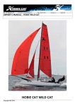
1
WELCOME TO THE
HOBIE WAY OF LIFE
Congratulations on the purchase of your new HOBIE 18’ and welcome to the HOBIE® sailing family. The HOBIE 18 cannot be
outgrown. A single adult can sail it at top performance - and a crew of four can cruise in comfort.
We offer this manual as a guide to increased safety and enjoyment of your new boat. The purpose of this publication is to
provide easy, simple and accurate instructions on how to get your Hobie 18’ ready for the water. Please read them carefully
and familiarize yourself with the boat and all of the parts spread before you.
Whether you are a new sailor or a veteran of many years, we recommend that you read this thoroughly before your first sail
and TRY IT OUR WAY FIRST! If you are new to sailing, this manual alone is not intended to teach you how to sail. There are
many excellent books, videos and courses on the safe handling of small sailboats. We suggest that you contact your local
sailboat dealer, college or Coast Guard Auxiliary for recommendations.
Watch for overhead wires whenever you are rigging, launching, sailing or trailering with the mast up. CONTACT OF THE
MAST WITH POWER LINES COULD BE FATAL! Be certain that the rigging area and the area that you will be sailing in are
free of overhead power lines. Report any such power lines to your local power authority and sail elsewhere.
We take pride in presenting the Hobie 18’ to you and hope that you'll take as much pride in owning her.
Fair winds and good sailing!
HOBIE 18 ASSEMBLY MANUAL
This assembly manual takes you stepby-step through the setting-up and
sailing of your new HOBIE 18.
This manual will help you understand
each part in detail.
Note that this manual applies for
both Hobie 18 SE and SX models.
Setting up your HOBIE 18
PAGE
Packaging Layout.................................2
Framing the Hulls .................................3
Sailing your HOBIE 18 ................PAGE
Installing the Trampoline ...................4-6
Balancing the boat ...................................26
Mast Assembly..................................7-8
Steering ....................................................26
Stepping the Mast ...........................9-11
Sail power.................................................26
Installing the Boom .............................11
Turning......................................................27
Installing the Jib Blocks ......................11
Launching.................................................27
Rudders and Tiller Cross Bar........12-13
Righting the boat ................................27-28
Raising the Main Sail ....................14-15
Docking and landing ................................28
Raising the Jib....................................16
Rudder tuning .....................................28-29
Dagger Boards ...................................17
Trailering...................................................29
Illustrations ....................................18-25
Maintenance.............................................29
Mooring.....................................................30
Hobie Class Associations........................30
Safety tips ..................................Back page
1
Packaging Layout
Figure 1
1.
2.
3.
4.
5.
6.
7.
8.
9.
10.
11.
12.
13.
14.
Port Hull
Starboard Hull
Back Bar
Boom
Tiller Cross Bar
Front Bar
Battens
Rigkit Box #1
Rigkit Box # 2
Rudders
Daggerboards
Sail Main and Jib
Trampoline
Mast (not shown)
Figure 2
See page 25 for descriptions
Hobie Cat 18 SE Rig Kit Box #1 (fig 2)
Description
1.
2.
3.
4.
5.
6.
7.
8.
9.
Shrouds, Forestay
7/16” Mainsheet 48’
5/16” Jib Sheet 45’
1/4” Trampoline Lacing - Center
1/4” Trampoline Lacing - Aft
Jib Luff Tensioner 2”
Jib Halyard Line 20”
Mainsheet Block Assembly
Jib Sheet Block
10. Jib Furling Assembly w/line 17”
Figure 3
2
Quantity
2,1
1
1
1
2
1
1
1
2
1
metal chips or dirt particles inside the bar which could
be hindering the bolt's progress.
*Port refers to left, starboard refers to right.
Framing the Hulls
(Recommend two people)
Tools-HEX wrench (provided) and a screwdriver with a
1 /4" head.
Retaining Channel
Front Bar Inboard Bolt 3 3/4"
Front Bar Outboard Bolt 2"
Rear Cross Bar Inboard Bolt 2 1/ 2"
Rear Cross Bar Outboard Bolt 2"
Lock Nuts for 802-359 Outboard Bolts
IMPORTANT
Read this before framing the hulls.
8
2
2
2
2
4
Prior to inserting each crossbar bolt, (Framing the
hull, step 5), apply approximately 1/8th (about one
teaspoon full) of the tube of silicon sealant around
the unthreaded portion of each bolt. This will seal
the area around each bolt and prevent unwanted
water from entering the hull.
1. Place the boxes on level ground with the seams
facing up. Cut the bands and open the lid. Remove the
sail, trampoline, rig kits, (two boxes), dagger boards,
rudders, and metal work modular packages. See Figure
1.
1. The dagger board and rudder are in cardboard
sleeves on each side of the hull.
6. Install the aft inboard bolt assembly on the starboard
side as described in step 5. It is important that the hulls
be parallel and level at this time. The frame will be very
difficult to attach to the hulls if they are misaligned.
Once the aft inboard bolts are installed, STOP. Do not
install the outboard bolts. This will be done later.
2. Leave the hulls in the end pieces so that they will be
supported in the upright position while being framed.
7. Place the front bar across the forward saddles. The
lengthwise track opening should be facing toward the
bows. See Figure 5.
3. Place the hulls 8 feet apart with the metal trampoline
track facing the inside.
4. Place the backbar across the aft saddles with the
traveler at the back.
5. Locate the bar firmly in the saddles and insert the aft
inboard bolt assembly under the port rail. *See Figure 4.
Start the bolt by hand to insure proper engagement. Do
not start the bolt with the hex wrench as you might cross
thread the internal assembly. If the bolt has trouble
advancing into the bar do the following;
Figure 5
8. With the bar seated firmly in the saddle insert the
forward inboard bolt assembly under the port rail. The
bolt is fitted into the bar by the same procedure as the
aft bolt assemblies.
9. Install the inboard bolt assembly on the starboard
side of the cross bar. If there are any problems
advancing the bolt refer to instructions in step 5A, B, C.
Once the bolts are engaged, STOP. Do not tighten them
down.
Figure 4
a. Rock the hull with quick movements as you turn the
bolt.
b. Double check the bars alignment with the saddle.
c. Have another person lift and lower the bow as you
turn the bolt.
If you are still having trouble advancing the bolt remove
the back bar from the boat and try the bolt in it. Look for
3
Figure 6
10. The four outboard bolt assemblies are identical. To
install, first slip the bolt through the outer end of the
corner casting and down through the rail of the boat.
Place the stainless steel channel over the bolt's
exposed section which is under the rail. Spin the nylock
nut on the bolt but do not tighten the bolt down at this
time.
TRAMPOLINE ASSEMBLY
11. Install all four outboard bolts in the manner
described in step 10. To insert the bolts in the front
corner castings it will be necessary to remove the cover
plates. Be careful when extracting the cover plate
retaining screw. It is made of aluminum and can be
galled. See Figure 6.
2. Lay the trampoline halves face down forward of the
front cross bar and between the hulls. The long row of
grommets should be on the inside and the short row of
grommets will be up at the bow. See Figure 8
1. Install the aft lacing strip. Feed the lacing strip into
the rear cross bar at the right just inside the hull where
the track has been cut away. See Figure 7. Center it
on the rear cross bar.
3. With the port trampoline half still face down, lead the
short side (without grommets) into the front cross bar at
the opening in the center of the bar and slide it over to
the hull. See Figure 9
12. Use the hex drive to tighten the bolts. Follow this
order to secure the bolts.
inboard front
inboard aft
outboard aft
outboard front
Port and Starboard
Port and Starboard
Port and Starboard
Port and Starboard
4. Pass the trampoline between the front cross bar and
the dolphin striker so that it is covering the bottom of the
cross bar.
It may be necessary to repeat this sequence more than
once to seat the front and back bars firmly into the
saddles. Once the bolts are tight check the dolphin
striker rod for looseness. If it is loose, tighten the nuts at
either end of the rod where it exits the outboard section
of the corner casting.
13. Replace the cover plates on the front corner
castings. Be careful not to damage the retaining screw
as you are installing it.
14. Re-check the cross bar after five hours of sailing. It
will probably be necessary to tighten some of the bolts.
Figure 7
4
Figure 8
Figure 9
5
5. Insert the aft outboard corner of the trampoline into
the extrusion on the inside of the hull and pull the
trampoline as far aft as it will go.
6. Repeat steps 2-5 for installing the starboard
trampoline.
7. In front of the rear cross bar there is a
inboard rail. Insert the port aft lacing line
on the port hull and exit it straight down.
the tail of the line and then pull the knot
rail.
hole in either
into this hole
Tie a knot in
up under the
Figure 10
8. Thread the lacing line from the inboard rail to the
corner grommet on the AFT lacing strip and then to the
corner grommet on the port trampoline. Temporarily tie
the line off to the rear cross bar.
9. Repeat this procedure for the starboard side of the
trampoline.
10. Attach the center trampoline lacing line to the
forward-most grommet on the starboard trampoline.
Lace it down to the rear taking out the slack as you go.
11. Untie the aft lacing lines and complete the lacing
starting at the outboard side and working toward the
center. See Figure 10. With use the trampoline will
stretch and require periodic re-tightening.
Figure 11
6
MAST ASSEMBLY
1. Support mast at both ends on saw horses or other
such devices. Ref: Illus. #1, Pg. 20.
NOTE: The style of rotator yoke shown in
Figure 12 is the older mast rotator style.
Current models do not have a pulley. See page
20 for details on the new style.
2. Spreaders. In the rig kit you will find all the parts of
the spreader assembly.
3. The larger of the two pairs of aluminum rods (1-1), is
the spreader arm. Attach it to the aft tab of the spreader
root (1-2). Use a 3/16" x 11/16" clevis pin (1-3).
turnbuckle on the bolt, pass the bolt through the mast at
the compression sleeve which is located 1 foot above
the mast base(1-14). The shackled end of the MRCY
should be behind the mast.
through the large hole in one arm of the MRCY (1-9).
Slide the toggle of diamond wire turnbuckle (1-13) over
the bolt and move it next to the MRCY arm.
14. With one arm of the MRCY and one diamond wire
turnbuckle on the bolt, pass the bolt through the mast at
the compression sleeve which is located 1 foot above
the mast base( 1-14). The shackled end of the MRCY
should be behind the mast.
4. Locate the slide (1-4) on the spreader arm so that the
large wing of the slide is closest to the mast, and facing
forward.
15. Slide the turnbuckle toggle of the opposite diamond
wire over the exposed portion of the bolt. Install the
remaining arm of the MRCY on top of the turnbuckle
toggle.
5. Line up the inboard hole on the slide with the
outboard hole on the spreader arm and insert the slide
adjustment pin 3/16" x 13/16" (1-5). The slide is now
positioned in the raked forward attitude.
16. Put the retaining nut (1-15) on the exposed threads
of the bolt and finger tighten only. It will be tightened
later. See figure 13.
6. Connect the smaller brace rod (1-6) between the
forward tab on the spreader root and the wing on the
slide, with the brace pin 3/16" x 9/16" (1-7).
17. Loosen the lock nuts at each end of the turnbuckle
body and expand the turnbuckle 2-1/2". Note that both
lock nuts spin in the same direction to unlock.
7. Secure all the clevis pins with the cotter keys
provided.
8. Repeat steps 3-7 for the opposite side of the mast.
18. Attach the opposite end of the diamond wire to the
diamond wire tang (1-16) which is located 2 feet below
the mast tang (1-17). Install clevis pins (1-19) and cotter
pins (1-20).
9.There will be two large cotter pins (1-8) left over, place
them to one side, they will be used later to retain the
diamond wires in the spreader arm tips.
10. Mast rotation control yoke (MRCY). In the rig kit you
will find the parts of the MRCY. You will also need the
diamond wires which can be identified by the
turnbuckles on one end.
11. IMPORTANT follow this sequence to assemble the
MRCY and diamond wires.
12. Hold the two arms of the
yoke (1-9) together at the
ends with the small holes.
Attach the small block (1-10)
and shackle (1-11) to this
end, see Figure 12. (There is
a short line packed with the
MRCY, set it to one side for
now.)
13. Pass the long bolt (1-12)
Figure 12
Figure 13
7
19. Slip the port diamond wire into the tip of the port
spreader arm. Make sure that the anti-chafing roller on
the diamond wire is above the spreader tip. Secure the
diamond wire by installing one of the long cotter pins (18) through the tip of the spreader.
25. Locate the shrouds and forestay in the rig kit. They
are packed together and are the only rigging which is
vinyl coated. The three wires are already attached to a
large shackle. Remove the pin from the shackle and
attach it to the mast tang (1-17) at the lowest of the.
holes in the tang. See Figure 15. Secure the safety wire,
which is attached to the thumbscrew, to the shackle
body. This will keep the pin from unscrewing.
20. Repeat this procedure for the starboard diamond
wire.
21. Tighten the nut (1-15) of the through mast bolt which
is at the lower end of the diamond wires.
26. The double trapeze wire has a single thimble at its
upper end. Engage this thimble to the shackle on the
opposite set of trapeze wires after you have inserted the
shackle through the upper set of holes in the mast tang.
See Figure 15.
22. Tighten the diamond wires by rotating the turnbuckle
bodies. The turnbuckles must be adjusted equally since
over-tightening one side will induce a bend into the
mast. See Figure 14.
Figure 14
WARNING
The diamond wire adjustment not only affects boat
performance but also affects the mast structural
integrity. If the diamond wires are loose or broken
the mast will be permanently distorted or could fail
completely. The diamond wires cannot be tightened
sufficiently by hand. It will require the assistance of
a wrench to make the last two or three revolutions
of the turnbuckle body. Additionally, the diamond
wire will stretch with use and require periodic
inspection and re-tightening.
23. Once the diamond wires are adjusted, spin the
locknuts up against the turnbuckle body tight. You can
do this by hand.
Figure 15
24. Tie a piece of string through one turnbuckle body
and over through the other turnbuckle body. This will
keep the turnbuckle from unscrewing.
8
STEPPING THE MAST.
DANGER - Do not attempt to step the mast in an
area of low overhead wires. A mast contacting an
electrical wire could be fatal.
1. Secure the four trapeze wires near the bottom of the
mast so that they will be out of the way while the mast is
being raised.
Jib Halyard Wire
2. Attach the jib halyard line to each end of the jib
halyard wire to form a very large loop. Tie the line
around the fork at the bottom of the forestay. The
halyard line must be connected to the wire before the
mast is raised or you will be unable to hoist the jib later.
See Illustration.
Luff Tensioner
3. Carry the mast over to the boat and place the hinge
of the mast base over the mast step which is located on
the front bar, see Figure 17. The sail track should be
facing down. Note: when lowering the mast over the
trampoline be sure to guide the mast rotation control
yoke between the trampoline halves.
Jib Halyard Line
Figure 16
Figure 17
9
CAUTION:
We recommend two people for stepping the mast. It
is heavy for one person and could slip causing
injury or damage.
8. Stand on the trampoline next to the back bar and
raise the mast to your shoulders. Make sure the shrouds
are not fouled and the stay adjusters are free before
advancing further. Do not raise the mast in an area with
any overhead wires. If everything is clear walk straight
ahead raising the mast as you go. See Figures 20, 21,
and 22.
9. Once the mast is in the vertical position lean your
weight against the
mast to hold it in
place. The second
person can now let
go of the mast and
attach the forestay
to the top of the
stay adjuster which
extends from the
roller
furler
assembly.
See
Figure 20
Figure 18.
Figure 18
4. With the hinge in place over the step insert the mast
step pin through the entire assembly so that it is visible
on the opposite side on the hinge.
5. Attach the bridle wires to the bow tangs. Attach the
roller furler mechanism between the bridle wires. Make
sure the oblong hole
in the roller furler is
aft. See Figure 18.
10. Remove the
mast step pin only
after the forestay
has been secured.
Store the pin in the
pouch on the
trampoline.
6. Attach the port
shroud to the port
stay adjuster and the
starboard shroud to
the starboard stay
adjuster. Secure the
shrouds to the top
hole in the stay
adjuster at this time.
See Figure 19.
11. Once the mast
has been raised
untie the trapeze
wires. In the rig kit
you will find a bag
which contains 4
trapeze dogbones,
4 rope locks and 4
trapeze adjusting
lines.
7. Secure the base
of the stay adjuster
to the anchor pin on
the respective hull.
12.
Tie
the
adjusting line onto
one
of
the
shockcord loops
which is located at
the outside rail
adjacent to the stay
adjuster.
Figure 19
10
Figure 21
Figure 22
block on the end of the mast rotation control yoke and
then feed it through the jam cleat. Tie a knot
in the end of the line so that it will not slip back through
the jam cleat.
See Figure 35.
13. Lace it through the rope lock and then through the
thimble at the end of the trapeze wire. Now tie the line
onto either end of the dogbone. See Figure 23.
14. Repeat this process for the other three trapeze wires
at the respective locations.
Once again, be sure to note that this is the older
style of mast rotator. With the newer style, the line
does not run through a pulley, but through a ring at
the end of the control yoke. Run the line through
the ring and into the jam cleat.
Figure 24
JIB BLOCK INSTALLATION
1. The large jib blocks are packed in the rig kits.
Remove the jib track end stop on the jib track and slide
the car on the bottom of the block into the track. See
Figure 25. Note that the slide adjustment knob is aft of
the block assembly.
Figure 23
BOOM INSTALLATION
1. Attach the gooseneck pin which extends from the
front of the boom to the gooseneck yoke on the mast.
See Figure 24.
2. Tie the line which was packed with the mast rotation
control yoke to the forward-most jam cleat on the boom.
See step 11 of mast assembly. Run the line through the
Figure 25
11
Hobie 18 and SX18 UPDATES
INSTALLING THE SAIL BATTENS
INSTALLING THE RUDDER ASSEMBLY
The rudders were updated after 1987. The newer
rudders use a black plastic cam to lock the rudder in the
down position. Locate the left and right rudder
assemblies. The left one has a red dot and the right one
a green dot. The tiller arms should have a slight bow
towards the centerline of the boat.
Unfold the sail and lay it out on the trampoline. There
will be a small bundle of thin lines tied to the top of the
sail. These are the batten tension lines. Tie the batten
tension lines to one of the small grommets at the end of
each batten pocket as diagramed in figure 28 (one to
each batten pocket). Tie the lines using a bowline knot
Figure 28
as found in the "knots" diagramed on page 4. It is best
to tie the lines all to one side of the sail. Insert each
batten (shortest batten at the top to longest batten at the
bottom of the sail).
Figure 26
As shown in the original instructions, position the
rudders at the transom. There are two bushings and two
washers provided with the each new assembly. Slide
the bushings in from the bottom and place the longer
one in the lower casting hole. Install a cotter key in each
rudder pin. Assemble as shown below. Then insert the
remaining cotter keys in the top of the rudder pins to
hold the rudders in place.
Note that the batten ends have a "V" jam cleat
molded into them. These "V" jam cleats will keep
the tension line from slipping in only one direction.
Note the hollowed-out side of the cleats. Pull the
line from the flush side toward the hollowed side.
The upper batten is narrower and has a different cleat
shape. To be sure this cleat works correctly, position it
so that the hollowed out side of the cap faces the
bowline that you have tied to the sail grommet. Position
the larger caps so that the hollowed sides face away
from each knot.
Following the diagram in figure 28, lace the tension lines
through each batten end cap. Pass the line through the
hole in the cap, then through the grommet on the
opposite side. For the smaller caps, pass the line over
the "V' cleat, pull tension forcing the batten into the
pocket, then pull the line into the cleat to hold it. For the
larger caps, pass the line through the second hole in the
cap, then pass the line through the first grommet and
back to the "V" cleat. Pull tension on the line forcing the
batten into the pocket and cleat it. Tie a small figure 8
knot in the end 1 of each line to prevent the battens
from falling from the sail if the line releases from the
cleat. Tension each batten so that the batten is well
seated and the wrinkles in the batten pockets are
removed. Excessive batten tension will cause the sail to
be more difficult to handle.
INSTALLING THE TILLER CONNECTOR
The tiller arms have swivels on the ends. Point the
connector rods upwards and slide the tiller connector
end fitting over the rods. Place the adjustable end of
the connector rod to the port (left) side of the boat. Pull
the small tabs forward and over the rod and lock them in
the slots. Rudder toe-in adjustments can be made with
the threaded end fitting on the tiller cross bar. Typical
adjustment has rudders in parallel.
Figure 27
12
3. To distinguish the port rudder from the starboard
rudder, the port rudder arm will bend toward the center
of the boat when on the port hull.
RUDDER AND TILLER CROSS BAR
INSTALLATION (Pre 1987 boats)
1. Disengage the tiller arm from the lower casting and
lock the tiller arm and rudder in the kicked up position.
This will pull the rudder blade up and out of the way so
the rudder pin can be installed.
4. Attach the tiller cross bar to the tiller arm as shown in
figure 31.
2. Hold the lower casting up to the transom of the boat
and fit the casting over the gudgeons. Slide the rudder
pin up through the casting and gudgeons with the hole
in the rudder pin closest the bottom. Once the hole in
the pin is above the casting at the lower gudgeon, stop
and insert the cotter key which is packed with the rudder
pins. Bend over the legs of the key to secure it in place.
The rudder can be lowered now. See Figure 29 and 30.
Figure 31
Figure 29
Figure 32
Figure 30
13
RAISING THE SAILS
1. Point the boat into the wind before you begin this
operation.
2. Lay the main sail out on the trampoline. Insert the
battens into the batten pockets starting at the top of the
sail and working your way down. The batten has a tip on
each end. The end without any holes goes into the sail
first. Slip the batten in until it seats into the batten
pocket protector at the leading edge of the sail.
3. Thread the batten tie through the aft batten tip and
the sail as shown in Figure 33. Secure the end of the
batten ties with a figure eight knot.
Figure 33
Figure 34
4. Attach the twist shackle on the end of the main
halyard to the grommet in the headboard and feed the
sail into the sailtrack in the mast. See Figure 34. Note
the metal ring connected to the twist shackle. It will
engage the latching mechanism at the top of the mast.
(see Figure 34a). Continue to raise the sail by pulling
the main halyard out from the base of the mast.
Figure 34a
5. It is recommended that you lubricate the leading edge
of the sail with paraffin from time to time to reduce wear
from the sail track. It will also make it easier to raise the
sail.
6. Raise the sail until the metal ring above the halyard
shackle engages the halyard hook at the top of the
mast. Store the excess halyard line in the pouch on the
trampoline.
7. Tie the downhaul line to the tack of the sail and lace
the downhaul as shown in Figure 35.
8. Attach the outhaul car on the boom to the clew of the
main. See Figure 36.
9. To lower the main, untie the downhaul and slide the
leading edge of the sail up the sailtrack a few inches.
Next pull hard on the main halyard and the metal ring
and the top of the sail will overrun the halyard hook,
rotate the mast to the starboard then release the
halyard.
14
Figure 35
Note: Old style mast rotator shown here.
10. Attach the three boom blocks to the hangers on the
boom. Secure the ratchet block to the top of the traveler
car. Thread the mainsheet through the blocks as shown
in Figure 37. Slip the other end of the mainsheet
through the traveler jam cleat, then guide the line
through the center of the traveler, and secure at the
dead eye on the back bar.
H18SX Downhaul Instructions
1. Using the twist shackle, attach the double block to the
sail luff grommet.
2. Tie off the downhaul line (10' of 3 /16" yt braid) to the
sail luff grommet.
3. Run the line through the cheek block on the left hand
side of the gooseneck yoke.
4. Continue to the double block, then to the cheek block
on the right hand side of the gooseneck yoke, then back
through the second sheave on the double block.
5. Tie off on mast downhaul cleat located below the
boom.
11. With only the main sail up tighten the shrouds. First
move the traveler car all the way over to the port side of
the back bar. Next pull the mainsheet in very hard. The
port shroud should be slack now and can be moved
down in the stay adjuster. Repeat this procedure for the
starboard shroud. Note: Tension on the shrouds must
be relieved before lowering the main sail. If you intend
to unstep the mast.
Figure 36
Figure 37
15
Raising the Jib
1. Attach the shackle on the end of the jib halyard wire
to the head of the jib.
2. Wrap the luff pocket of the jib around the forestay and
engage the zipper an inch or so. Next thread the jib
halyard line inside the luff pocket. See Figure 38.
Figure 39
9. Thread the remaining portion of the jib sheet through
the starboard jib block in this same fashion.
10. The roller furler line can be temporarily secured in
the jam cleat on the back side of the front cross bar.
Figure 38
Roller furler line adjustment on
take up spool.
3. Raise the sail by pulling on the jib halyard line and at
the same time advance the zipper down the luff until the
jib tack is even with the roller furling housing.
a. Disconnect jib clew blocks
from jib clew.
b. Pullout the roller furler line
from the housing until the take
up spool is empty and secure the
line to the cleat on the front bar.
c. Wrap the sail clockwise
around the forestay until it is
completely furled.
d. Reattach the jib clew blocks to
the jib clew. The jib is now in the
furled position.
4. Attach the jib tack to the shackle on the neck of the
roller furling housing. .
5. Untie the jib halyard line and connect the luff
tensioner to the block on the end of the jib halyard.
Thread the tensioner down through the tack shackle,
then back up through the block on the jib halyard.
Secure the line in the jam cleat on the sail. See Figure
39.
6. IMPORTANT. Only apply the jib luff tension after the
shrouds and forestay have been tightened. To do so
beforehand could result in the jib halyard being broken
when the slack in the shrouds is taken up.
To unfurl the jib, release the
roller furler line which is cleated
on the front bar, and pull on the
jib sheet.
7. Attach the jib clew blocks to the jib clew, see Figure
40.
8. Thread the jib sheet through the port jib block, then
around the jib clew block. Take the line back and tie it
off at the becket on the jib block. See Figure 41.
Figure 40
Figure 41
To furl the jib, release the jib sheet (both port and
starboard) pull the furler line until the jib is completely
furled. Do not partially furl the sail, this will cause
uneven stretching of the exposed sail.
16
Figure 42
3. When raising or lowering the board do not rock it fore
and aft. This will cause damage to the trailing edge. Pull
the leading edge of the dagger board aft about 1/4 of an
inch so that it is not contacting the lip of the deck and it
can be easily moved up and down.
DAGGER BOARDS
1. Slip the shock cord through the hole in the upper
portion of the dagger board, take both ends to the hole
on the out board deck flange. Pass both ends through
the hold and tie a knot under the rail.
4. IMPORTANT. If you expect contact with an object or
the shore, pull the dagger boards up out of the way.
Severe damage can resuIt if the boards contact any
solid object regardless of the speed.
2. Pass the rope handle through the same hole in the
dagger board as before. Tie the two ends together to
form a large loop which will serve as the handle. See
Figure 42.
17
HOBIE CAT 18
’
18
43
44
45
46
47
48
49
50
51
52
53
54
55
56
57
58
59
60
61
62
63
64
65
66
67
68
69
70
71
72
73
74
75
76
INDEX
NO. DESCRIPTION
1 Arm
2 Brace
3 Slide
4 Diamond Wire (one side)
5 Gooseneck Yoke
6 Check Block
7 Mast Rotation Line
8 Modified Swivel Block
9 Shackle
10 Mast Rotation Assembly
11 Pin-Pawl Bearing, 5.5.
12 Ring-Halyard Line
13 Hook for Halyard Lock Assembly
14 Jib Furling Assembly
15 Bridle Wire Assembly
16 Screw - 5.5. (1/4 x 20)
17 Back Up Plate - Bow Tang
18 Nylock Nut (1/4 x 20)
19 Mast Tang
20 Trapeze Wire (one side)
21 Shackle
22 Shroud
23 Pigtail with Swivel
24 Jib Halyard Block Assembly
25 Clevis Pin
26 Mast Hinge Casting
27 Mast Base Casting
28 Screw RD. HD. 1/4 x 20
29 Star Lock Washer
30 Sheave
31 Clevis Pin
32 Washer
33 Bushing
34 Pad. Mast step
35 Mast Step
36 Rivet
37 Left Front Corner Casting
38 Boom Outhaul Slide Assy.
39 Cotter Key
40 Outhaul Car
41 Clevis Pin
42 Sheave
19
Rollers
Pin
Outhaul Line
Boom
Boom Block
Single Block with Becket
Boom Block
Main Sheet Line
Triple Block
Left Rear Corner Casting
H-18 Ratchet Block
Traveler Assembly
Channel
Bushing
Bolt 3/8 x 16 - 3 (rear only)
Swivel Main Sheet Fairlead
Rear Crossbar
Tiller Crossbar with Rudder Adjuster
Tiller Arm Bent
Upper Rudder Arm Right/Starboard
Right Rear Corner Casting
Channel
Nylock Nut - versus drawing
Upper Rudder Casting
Lower Rudder Casting - bare
Rudder Pin
Lower Gudgeon
Jib Sheet Line
Jib Sheet Block
Front Crossbar Assembly
Right Front Corner Casting
Bolt - Cover Plate
Flange
Storage Cover w/Handle
New Style Yoke
Old Style Yoke
Illustration No. 1
Mast Assembly
1-1
1-2
1-3
1-4
1-5
1-6
1-7
1-8
1-9
1-10
1-11
1-12
1-13
1-14
1-15
1-16
1-17
1-18
1-19
1-20
Spreader Arm
Spreader Root
Clevis Pin 3/16" x 11/16"
Slide
Clevis Pin 3/16" x 13/16"
Brace
Clevis Pin 3/16" x 9/16"
Cotter Pin
Mast Rotation Control Yoke
Block
Shackle
Bolt 4-1/8" Lg.
Diamond Wire
Mast Base Assembly
Nut Nylock
Diamond Wire Tang
Mast Tang
Mast Extrusion
Clevis Pin 3/16" x 1/2"
Cotter Pin
20
Illustration No. 2
Jib Halyard Assembly
2-1
2-2
2-3
2-4
2-5
2-7
2-8
2-9
2-10
2-11
2-12
Jib Block Housing
Jib Halyard Wire
Luff Tensioner
Jib Halyard Line
Jib Block Sheave
Clevis Pin
A Cotter Pin
Swedge
Thimble
Block
Shackle
Illustration No. 3
Tiller Connector Kit
3-1
3-2
3-3
3-4
3-5
3-6
3-7
3-8
21
Bolt
Half Ball
Tiller Crossbar
Plastic Washer
Tiller Arm
Washer
Spring
Nut
*Rudder system Pre-1987 shown
Illustration No. 6
Rudder Assembly
6-1
6-2
6-3
6-4
6-5
6-6
6-7
6-8
6-9
6-10
6-11
6-12
6-13
6-14
6-15
Rudder Blade-Drilled
Lower Rudder Casting Assembly
Port Upper Rudder Housing Assembly
Nut Nylock
Bolt 2" Lg
Spring
Delrin Screw
1 / 4" I.D. Nyliner
Rudder Cam
Upper Rudder Housing Casting
Rivet
Locking Sleeve
Pin Upper Rudder Housing
Pin Lower Rudder Housing
Tiller End Cap
Illustration No. 7
Outhaul Car Assembly
7-1
7-2
7-3
7-4
7-5
7-6
7-7
7-8
22
Adjuster Pin Retaining Ring
Outhaul Slide Car
Clevis Pin 1 /4" x 7 /8"
Ball Roller Bearing
Clevis Pin 1 /4" x 5 /8"
Pin-Bearing
Sheave
Cotter Key
Illustration No. 8
Traveler Assembly
8-1
8-2
8-3
8-4
8-5
8-6
8-7
8-8
8-9
8-10
1- 1/4" Lg H.H. Bolt
Deck Plate
Sheave
Spacer
Car Assembly
Cotter Pin
H.H. Nuts-Nylock
Bearing Cylinder
Pin-Clevis
Bearing Ball
Illustration No. 9
Roller Furler Assembly
9-1 Upper Retaining Ring
9-2 Top Nyliner
9-3 Bottom Nyliner
9-4 Yoke
9-5 Housing
9-6 Interior Retaining Ring
9-7 Bearing Sleeve
9-8 Bearing Race
9-9 Bearing Cage
9-10 Bearings
9-11 Tube
9-12 Spool
9-13 Screw Truss Head
23
Illustration No. 10
(old style)
Dolphin Post Assembly
10-1 Screw RHMS
10-2 Internal Lock Washer
10-3 Washer
10-4 Mast Step Pad
10-5 Bushing
10-6 Mast Step Casting
10-7 Dolphin Striker Post
10-8 Dolphin Striker Sleeve
Illustration No. 11
(new style)
Dolphin Post Assembly
11-1 Screw RHMS
11-2 Washer
11-3 Bearing
11-4 Mast Step Casting
11-5 Dolphin Striker Post
11-6 Dolphin Striker Sleeve
24
Illustration No. 12
(new style)
Tiller Connector
12-1 Tiller Connection Rod
12-2 Tiller Arm Swivel End Cap
12-3 Tiller Arm Insert
12-4 Bolt
12-5 Washer
12-6 Insert Bearing
12-7 Retainer Clip
12-8 Screw
17
Parts Relating to Diagram on Page 2
2 Rudder Pin
2 Cotter Pin for Rudder Pin
2 Jib Clew Block
1 Shackle
1 Gooseneck Vertex
1 Clevis Pin "
1 Split Ring
1 Gooseneck Bolt
1 Nut
11 Trapeze Seat Assy.
2 Trapeze Seat
2 Trapeze Hook
2 Trapeze Lacing Line 6'
12 Mast Rotation Control Yoke Assy.
2 Mast Rotation Control Yoke
1 Shackle 1 Block
1 Mast Rotation Control Line 3'
1 Mast Rotation Control Yoke Retaining Bolt
1 Retaining Bolt Nut
17 A 1 Down Haul Line
18 Bridle Wire Clevis Pins
13 Spreader Assy.
4 Bridle Wire Clevis Pins
4 Split Rings
2 Spreader Arm
2 Brace
2 Slide
2 Spreader Arm Root Pin 3/16" x 11/16"
2 Spreader Arm Slide Pin 3/16" x 13/16"
4 Brace Pin 3/16" x 9/16" 8 Cotter Pins 1/2"
2 Spreader Arm Tip Cotter Pins 3/4"
18A Diamond Wire Clevis Pins 1
2 Upper Diamond Wire Clevis Pins
2 Cotter Pin
19 Mast Step Pin
1 Mast Step Pin
1 Split Ring
1 Mast Step Pin Retaining Line
14 Adjustable Trapeze Equipment
4 Dogbone
4 Rope Lock
4 Adjustable Trapeze Line 30"
20 Traveler Bearing Kit
1 Traveler Bearing - Ball
1 Traveler Bearing Slug
1 Long Cotter Pin
15 Dagger Board Kit
2 1/4" Shock, Card 46"
2 1 /4" Rope Handle 29"
21
8 Retaining Channel
2 Front Bar Inboard Bolt 3 3/ 4"
2 Front Bar Outboard Bolt 2"
2 Rear Cross Bar Inboard Bolt 2 1/2"
2 Rear Cross Bar Outboard Bolt 2"
4 Lock Nuts for 802-359 Outboard Bolts
2 Bridle Wire
2 Diamond Wire
2 Trapeze Wire
16
2 7 Hole Stay Adjuster Assy.
2 Drain Plug
2 Drain Plug Gasket
1 Tiller Connection Kit
25
Refer to the sail trim diagram below for approximate sail
settings for the different points of sail or directions you
will be sailing. Note the "can't sail zone". You cannot sail
in this direction due to the fact that the sail will luff
constantly when pointed into the wind. If you get stuck in
irons (or stop pointed into the wind) you will need to
reverse the rudder and push the sail forward to backwind it. The jib should be back winded by the crew to
assist. This will back the boat up. Reverse the rudders
and let the sail out until the boat is positioned more
across the wind (close reach). Then you can correctly
trim the sail and start moving forward.
SAILING YOUR HOBIE 18’
Safe and sane guideline for the beginner; and an easy
review for the experienced.
Always wear a life jacket when boating.
BALANCING THE BOAT
When sailing, sit on the upwind side of the boat (wind on
your back) just in front of the tiller, facing the sail.
Balance your weight further outboard as the boat begins
to tip or heal over with the wind in the sails. Tuck one
foot under the hiking strap for balance. Use your hand
that is forward to hold and control the mainsheet. Use
your hand that is aft to steer.
STEERING
Steer the boat by pushing the tiller away from you to
turn towards the wind. Pull the tiller towards you to turn
away from the wind. Keep the movement of the tiller to a
minimum to prevent over-steering. This will help you
keep the boat moving in a straight line as you pay
attention to other watercraft and sail adjustments.
SAIL POWER
Face the sail in order to pay close attention to the trim or
adjustment of the sail. When the front of the sail, just
behind the mast, luffs or flutters in the breeze, you lose
power. To start moving, pull the sail in just enough to
stop the sail from luffing. There are also short ribbons
hanging on either side of the sail. Follow the diagram of
sail and course adjustments above using the "tell tails"
to get the most performance out of the sail for all angles
of sailing. The tell tails react to air flowing over the sail
and will help you see that the sail is pulled in too tight or
too loosely. If you pull the sail too tight you will stall the
sail power. Ease the sail out until it luffs, then pull it in
just a little until it stops luffing. You will adjust the trim
whenever the wind changes direction or you change
course.
WIND
ach
dium
ea
c
R
d
oa
Br
d
WIND
H
au
le
AR
ch
Rea
h
Me
IS
IN
e Re
ach
e Re
Clos
Mediu
Downwind Run
Clos
TH
d
IL
le
C
au
SA
H
lo
se
T
se
N'
lo
EA
CA
C
FALLING
OFF
m Re
Br
ach
oa
d
Re
ac
h
HEADING UP
26
COMING
ABOUT
into deep enough water to lower the rudders. It is
possible to launch in shallow water with the rudders
partly up. Try not to steer with too much force on the
rudders until you lock them in the down position. Keep
the sail loose and trimmed out completely until you can
power up and steer away from any obstacle. Trim the
sail in quickly to get the boat moving forward and steer
away from the wind slightly to prevent stalling into the
wind.
TURNING
To tack or turn the boat into and across the wind to the
opposite direction (also known as "coming about"),
follow the points of sail guide illustration and take the
boat to the close hauled point of sail. This is when you
are nearly 35 degrees from sailing straight into the wind.
With the boat moving forward and not stalling, push the
tiller away from you slowly. When the boat is pointing
straight into the wind the boat will become level. Ease
the mainsheet trim out just a little. At this time move
your body to the other side of the boat, switch hands
with tiller and mainsheet and begin to bring the rudder
back to straight. The crew should move across the
trampoline at the same time. The crew is responsible to
ease the jib sheet just after the main sail is released and
sheet the jib onto the new course before the mainsheet
is trimmed. This action by the crew will prevent the boat
stalling head to wind. As the boat comes across the
wind and falls off onto the opposite, close hauled point
of sail, bring the tiller all the way back to the straight
position and pull the mainsail back in for the proper sail
trim. If you stall pointing into the wind and you cannot
steer the boat, refer back to the sail power description
concerning getting stuck in irons.
When launching from a beach where the wind is blowing
from the beach towards the water you simply keep the
boat pointed into the wind. Drift backwards with the
rudders in the up position and your weight towards the
front of the boat. Stay forward as the boat drifts into
deeper water.You can hold the sail out to catch wind
backwards to increase reverse speed. Then move to the
rear and lower the rudders. It will be easiest to lower
only one rudder while moving backwards. Then lower
the other when the boat begins to move forward again.
Be aware of the intended direction you wish to sail when
lowering the rudder and steer the boat as the rudder
drops into the water. There will be a lot of force on the
rudder to turn one way or the other when going
backwards. Plan ahead and steer the rudders so that
they will be pointing in that direction before dropping it
into the water. Steer the boat while going backwards so
the bow turns away from the wind and toward the
direction you wish to sail. As the sail begins to fill with
wind, the boat will slow then begin to move forward.
Trim in the sail and off you go.
When sailing downwind, the turn from one point of sail
across to the other is called a jibe. The jibe is completed
by turning away from the wind (falling off) to the
opposite point of sail rather than into the wind as when
tacking. Care must be taken when attempting a jibe as
the boat will be at full power and you cannot easily depower it without turning back into the wind. Also, be
aware that the boat will be less stable in this maneuver
as the sail will now have to swing clear across from fully
out one side of the boat to fully out the other.
RIGHTING THE BOAT
If you tip the boat over, stay with the boat. The boat will
not sink and is easy to right. It is not necessary, but it is
easier, to right the
boat when the bow
and the mast are
pointed into the
wind as in the
following diagram.
To start a jibe, turn the boat away from the wind and let
the sail out slowly. Keep the turn going at a steady rate
and begin pulling the sail back in as the boat nears the
straight downwind direction. This will help prevent the
sail from slamming all the way across when the sail fills
from the opposite side. Duck below the sail to avoid
getting hit as the wind fills the sail from the opposite side
and swings across the boat. Attempt to control the
speed of the sail while it crosses the deck by
maintaining some tension on the mainsheet. Then ease
the mainsheet out quickly as the boat turns past the
downwind direction onto the new point of sail. Trim the
sail correctly for the desired point of sail.
There will be less
wind resistance
and better control
in this position. Be
sure the mainsheet
is released, then
swim around to the
bottom of the boat.
Skipper and crew should climb up on the hull and stand
up. Using the righting line, skipper and crew pull the
righting line that is against the upper hull and hold the
LAUNCHING THE BOAT
Launching the boat is easiest when the boat can be
pointed into the wind to keep it de-powered and floated
27
stall the boat. Raise the rudders and drift back onto the
beach. Always keep the boat pointed into the wind
while beached and keep the sail trimmed out and uncleated.
line while slowly leaning back away from the trampoline.
Lean to approximately 45 degrees for best leverage. As
the mast and sail lift out of the water and the upper hull
begins to drop back into the water, drop down to your
knees then into the water. Hold onto the righting line
near the crossbar or the crossbar itself near the hull that
you were standing on. This will prevent the hull from
being lifted into the air by momentum which could cause
the boat to capsize once again. Be well aware of the hull
and crossbar coming down over your head. Holding the
crossbar or righting line will also insure that you remain
with the boat when it is righted. Climb aboard and
continue sailing. Be well aware of the hull and crossbar
coming down over your head. Holding the crossbar or
righting line will also insure that you remain with the
boat when it is righted.
RUDDER TUNING
You may adjust the rake of your rudder blades on your
Hobie Getaway. The amount of rake in a rudder blade
affects the "feel" at the tiller. Basically, more forward
blade rake neutralizes the pull on the tiller and less
forward rake increases the pull on the tiller. Tuning
blades for a comfortable feel is a matter of individual
preference but a close to neutral "feel" generally
provides the best steering. The following sketches are of
a Hobie 16 rudder assembly
but the adjustments are the
same.
1) The first step in making
any rudder rake adjustment
is to determine the existing
12"
rake. This is done with the
1-1/8"
rudder assembly hanging on
the boat's transom, blade
down and locked. Using a
straight edge or snap line,
extend the centerline of the
rudder pivot pins down, Aft for more pull on
the tiller
across the leading edge of
Forward for less
pull on the tiller
the blade and draw a pencil
line along that length. Measure the distance from the
pencil line to the most forward spot 12" down the blade
from the bottom of the casting.
DOCKING
Docking the Getaway properly will prevent damage.
Always dock and rig on the leeward side of a dock (the
side the wind reaches last). Come in slowly and always
be aware of the wind direction so you can properly depower the boat when needed. The stronger the wind the
more difficult the docking will be. Until you feel
confident, you may want to practice with a friend who
will remain on the dock and help slow you down if
necessary.
BEACH LANDINGS
Landing on a beach is simple. The idea is to reach the
beach in the point of sail nearest straight into the wind
as possible. This will assure that you can properly depower the sail once beached.
Rudder blade rake is pre-set at the factory to 1-1/8".
This amount will be best for the average sailor and is a
good starting point from which to begin any
adjustments.
Approaching a beach when the wind is blowing from the
beach out towards the water will require some planning
so that you maintain power. Turn into shore just before
the hulls or rudders touch bottom. Plan so the final tack
towards the location you choose to land is the tack that
is nearest straight into the wind. Get a little closer to the
beach than you need on the pervious tack to account for
wind shifts in direction and speed. This will give you a
little room for error. This will allow you to point a little
further away from the wind after the tack to gain speed
before heading up into the beach to de-power at the last
moment.
2) To make any adjustment to the rake, unlock the tiller
arm from the rudder housing and leave it unlocked.
3) If you wish to increase the amount of forward rake in
the rudder blade, turn
the rake adjusting screw
counterclockwise using
a 3/16" Allen wrench.
Determine the increase
in the rake by extending
a new line from the
centerline of the pivot
Screw
pins. Re-measure the
distance from the pencil Sketch B
line to the leading edge.
When approaching a beach when the wind is blowing
onshore, sail in towards the beach from either side of
the landing spot. Sail in just short of touching the bottom
with the rudders. Allow some distance to turn the boat
out towards the water and into the wind just out from the
landing spot. Turn sharply to head into the wind and
28
Continue to adjust and measure until you have the desired
amount of forward rake.
4) If you wish to decrease the amount of forward rake turn
the adjusting screw clockwise using a 3/16" Allen wrench.
Check the decrease in the rake by the procedure in step 3
above .
5) Next, while holding the rudder forward against the lower
casting, carefully latch the tiller arm down onto rudder
housing. Loosen the adjusting screw on top of the tiller arm
about 3/4 turn. Slide the adjusting screw forward (toward
bow of boat) until it stops, then retighten. See sketch C.
Screw
Sketch C
"tail dragging" of the towing vehicle, impairing steering
and raising headlights into the eyes of oncoming traffic.
Too little or negative weight on the hitch, and the trailer
will sway or "fishtail". The solution to proper distribution
is often adjusting movable gear. A more permanent
solution is to shift the axle position before taking your
boat to water the very first time.
TOWING
Extra caution is necessary when towing any trailer. The
heavier the rig, the more time required to accelerate,
pass, and stop. For this reason, the maximum speed for
vehicles with trailers is less than without a trailer in most
states. A long rig requires a larger turning radius. Curbs
and obstructions should be given wide clearance. Most
boats on trailers obstruct the rear view of the driver.
When this happens, an additional rear view mirror on
the right side of the towing vehicle is required by law.
The trailer boatman should be familiar with traffic and
highway laws relating to the towing of trailers. Towing a
Hobie has particular hazards that should be mentioned.
A Hobie is very wide. Obstacles should be given plenty
of room when you are passing them. Tie down straps or
lashings should be of sufficient size and diameter and
placed on all four corners.
The mast support on a trailer is subject to a lot of
side-to-side motion and consequently may fatigue
where it is welded to the trailer. All this can be reduced
by tying a line from each bow to the mast support. This
will stiffen the rig up and prolong the life of the trailer.
6) Hobie Cat rudder
blades are preset to
break away from the
locked down position at
17-26 pounds by testing
with a line around the
rudder blade seven
inches above the lowest
tip of the blade. Once
the rake is changed, the
breakaway
tension
should be rechecked.
The tension may be
adjusted by turning
the 3/4" internal
screw
in
the
housing. The screw
tensions an internal
spring.
Turn it
clockwise
to
increase
and
counter clockwise to
decrease the tension.
LAUNCHING AND RETRIEVING
Prepare boat for launching at the top of the ramp or
parking facility. Remove all tie-down straps, check boat
plugs and fasten boat painter. Do not release winch line
until the boat is in the water. Back trailer to the left if
possible; backing left gives better launching visibility.
Avoid dunking wheel bearings wherever possible. Never
leave the towing vehicle unattended on the ramp with
only the parking brake set. If vehicle must be left while
on the ramp, set transmission in "park" or first gear, in
addition to setting the parking brake. In retrieving your
boat, make sure that the boat is properly placed on the
trailer. Pull trailer up steadily to prevent spinning the
wheels.
TRAILERING
MAINTENANCE
CAUTION: Boat and mast should be securely attached
to trailer with adequate tie-down straps. Failure to do so
could cause extensive damage or serious injury!
Lights: Most state laws require two red taillights on the
rear that may be combined with the stop and turn
signals. Vehicles over 80 inches in width require
clearance lights. If lights are dunked, waterproof light
fixtures should be used. If water is allowed to enter, the
lamp may crack and short out the entire system. Water
also promotes contact corrosion. Always carry spare
LOADING YOUR TRAILER
The weight of the boat, equipment and additional gear
should never exceed the manufacturer's rated weight
capacity. Proper distribution of the load is of vital
importance. Too much weight on the hitch will cause
29
lamps. The wire coupling to the towing vehicle should
be high enough to stay dry. Never rely on the trailer
hitch for ground connection. Four-pole connectors
should be used.
A good anti-fouling paint can be applied for some
protection from marine growth before mooring. Before
painting, it is suggested that the area be masked off to
ensure a clean line. No friction reducing paints or agents
may be employed on a Hobie Cat during competition.
The mast should not extend over three feet behind the
rear light assembly.
HOBIE CLASS ASSOCIATION
Wheels: Tires should ALWAYS be inflated to
manufacturer's recommended pressure. Always carry a
spare wheel and a jack that fit the boat trailer. If wheel
bearings are always dunked, waterproof bearings and
caps should be considered. If water is allowed into the
hub, lubricating grease will float away and bearings will
burn out or seize, causing damage and a safety hazard.
Waterproofed bearings should be inspected prior to
each boating season, others more often. Special care
should be given when traveling on unimproved
roadways with small diameter wheels.
The Hobie Class Association was started by a group of Hobie
owners who got together back in 1968 to organize some
racing and other activities. Hobie was the mainstay of the
group promoting the activities himself. At that time, it wasn't
really a class association but simply a group of owners
wanting to have fun with their new toys. Hobie would write
brief newsletters from the factory announcing regattas as they
developed across the country. He published a set of class
rules rigidly restricting changes and modifications which can
be made to the boat. As the class started to grow, people were
hired to help administer the program. At that point, the
association became a little more formal: the groundwork for
the establishment of fleets was developed and the Hobie Cat
Hotline was initiated as a class newsletter.
The Class Association was originally organized around one
basic consideration: to extend each Hobie owner's enjoyment
through organized, family oriented activities. Innovations were
made in racing procedures and the regatta structures. A
policy of including the whole family in the activities developed
to assure everyone would have fun at Hobie regatta. The
Association continually strives to develop better programs so
owners may further enjoy their Hobies
If a spare wheel is not available, a spare wheel bearing
set should be taken on long trips in case the grease seal
has been broken.
FRAME AND ROLLERS
Rust should not be allowed to accumulate. Remove rust
and repaint with anti-rust paint. Some trailers offer
galvanized coating to prevent rust. Rollers should roll
freely and should not have checks, breaks or flat spots.
TOWING VEHICLE
Most vehicles are limited in towing capacity. Towing
heavy loads places extra demands on the engine,
transmission, brakes and other systems vital to the
vehicle. Towing "packages" are available through most
auto dealers and should be considered for heavy boats.
KNOW YOUR KNOTS
MOORING:
Mooring a Hobie is not recommended as it will cause
deterioration and discoloration of the hull. If, however, it
has to be moored for a short time the main thing to
remember is make sure everything is snug and secure.
FIGURE 8 KNOT
Obviously the first thing to do is tie the boat securely to
the mooring. Then furl the sail and secure all gear so it
can't chafe when swells and boat wakes rock and thrash
to boat. Last, but very important, be sure all shrouds are
tight so the mast can't flop and fatigue the wires in the
shrouds. Many an unsuspecting boat owner has moored
his boat for a few days only to return to find his mast
laying in the water. The easiest way to tighten the
shrouds is to run a line around a shroud, under the
boom and around the other shroud. Tightening this line
will tighten the shrouds and minimize fatigue and wear.
Another method is to install a shroud tension adjuster (a
single line tied to the bridle intersection and run through
a cleat near the mast on the front cross bar). Tightening
the shroud adjuster will tighten the shrouds.
BOWLINE KNOT
FIGURE 8 KNOT
AT END OF LINE
HALYARD KNOT
CLEATING OFF A LINE
30
mast bend both ways. Also, the 18 has a controllable
mast rotation device and an internal roller outhaul.
Being as this boat does have a few more strings and
lines on it than a 16, we designed and specially tooled a
boom that carries internally your outhaul and mast
rotation control, to try to keep the lines tucked inside as
neatly as possible.
All of the fittings on the boom are moveable;
with the loosening of a screw you may slide any of the
leads fore or aft as you find convenient. This really
made it simple on us designwise because we didn't
have to figure out exactly where everything should go,
and you, in turn, aren't stuck with our decision and can
move them around until they are comfortable to you.
Being able to control the mast rotation, tension
the diamond wires, and even rake the spreader on the
diamond wires (this may be moved fore and aft to pump
the mast either forward or back slightly) leaves a
tremendous amount of room for tuning the sails on the
18 and getting the maximum performance out of them.
To keep the mast clean and allow for an efficient air
flow, we ran an internal main halyard (the jib halyard is
already internal inside of the jib luff).
Another set of features on the 18 which I like
are the inspection plates in each hull. You can look in
there and see what's happening, and the holes are big
enough so you can stuff things away in the hull. . .
lunch, beer, jackets, whatever. Also, there is a goodsized pocket on the trampoline that halyard ropes and
assorted odds 'n ends may be stuffed into so you don't
have a lot of loose line laying around on your boat.
It is important to remember that the "fastest"
boat isn't necessarily the "best" boat for everyone. What
is the best boat - whether it be an 18, a 16, a 14, or
some other type of boat altogether, is the one that best
suits an individual's particular wants and needs. A boat
that is the most useful to you personally, one that you
will get the most enjoyment out of, is the best boat in the
world!
About your Hobie 18’
There are ways of going faster on a catamaran,
while still staying within the eight foot beam, trailerable
size range. Basically, you put a taller mast on, use
daggerboards, and go to a half round hull shape.
The Hobie 18 is the end result of our efforts - mine, Phil
Edwards' (my longtime friend and co-designer of the
18), and those of all the guys on our research and
development team.
First thing, on the 18 you've got daggerboards .
. . the price you pay having symmetrical hulls. And while
they do keep you a little busier - having to raise them up
or down at times - I have found that our boards, with
their raked back leading edge, and the fact that they fit
their trunks well, are really quite easy to use. One quick
tug and they spring up or down, or lock part way, almost
automatically. Under heavy kelp conditions the boards
can be pulled up part way, leaving a very raked back
leading edge which will help dispense of kelp and
sometimes even knock it down and keep it from hanging
up on the rudders.
I find the 18 rudder assembly and locking
mechanism to be much easier to use than the 16's,
which is darn good. Locking the rudders down on the 18
is a more "natural" movement, which in itself is an
improvement over the 16.
The Hobie 18 has a built in mainsheet traveler
car which can be used either as a roller bearing type
traveler or a slider, as we furnish both rollers and slugs.
I have found the best combination is one roller and one
slug. This allows the traveler to move reasonably free
but still provides enough friction so that when you're
pumping or sheeting your main, the traveler car does
not want to keep coming at you all the time. Also, the
fact that it is built internally into the rear crossbar makes
for a clean and neat installation.
One of the really neat features on the 18 is the
roller furling jib. When you're sitting out there luffing,
waiting to start a race or just taking it easy, or even if
you just want to single-hand sail, all it takes is one
simple pull of the string and in about two seconds your
jib is neatly put away. And, of course, it is the ultimate
detuner for heavy air when you want to get some sail
area off the boat fast. Whereas most roller furling jibs
are attached permanently to the forestay, on the Hobie
18 we put a zipper luff with an internal halyard inside the
zipper so you may take the jib off the boat at any time.
That same halyard also serves as your luff tension,
which is another reasonably critical tuning device.
The Hobie 18 is an extremely "tuneable" boat.
You've got all the adjustments - fore and aft, in and out luff tension on your jib, and, with the diamond
spreaders on the mast, you are also able to control your
Hobie Alter
31
Part # 63450001
CAUTION / SAFETY TIPS
•
Watch for overhead power lines. Never rig,
trailer or sail the boat near overhead power lines.
•
Contact with a power line could be fatal.
Install Drain Plugs. Even the most experienced of
boaters forget to install the drain plugs sometimes.
When installing the plugs, be sure that the threads
and gaskets are free of sand/ grit. Any debris on
•
the plug could cause a water leakage.
Sail to your experience. Do not try to do more
than you can. Do not take the Hobie 18 out in the
surf and do not head out for the ocean unless you
•
are a real professional.
Wear a life jacket. Wearing life vests while sailing
is something that is very important and should be
done at all times. Also, a sailboat could sail away
by itself if a person were to fall overboard. The best
advice to a sailor is to stay with the boat. If they
happen to fall overboard, or when righting the boat,
they should hold onto the boat and not let it get
•
•
away.
Hobie 18’ in Flight
Learn the right-of-way rules and when in
doubt, give way to others.
HOBIE CAT
4925 Oceanside Blvd.
Oceanside, CA. 92056
Phone (760) 758-9100 Fax (760) 758-1841
When trailering the Hobie 18 be sure to tie the
boat and all the loose parts to the trailer in a
secure manner. Stop and check the tie downs
•
often.
Hobie Cat does not recommend leaving the
Hobie 18 in the water on a mooring. Accelerated
wear to the boat and rigging will be experienced.
Damage to the hull material is possible. Limitation
of the mast rotation and tensioning of the rigging
are required to lessen this wear. Inspect rigging
often and tape rigging rings and shackles to prevent
loosening.
WWW.HOBIECAT.COM
For your nearest HOBIE dealer
or
for help and information call:
1 (800) HOBIE - 49
32