1
Instructions – Parts List
Parts
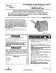
Delta Sprayt
HVLP Spray Gun
308741N
100 psi (0.7 MPa, 7 bar) Maximum Working Fluid Pressure
100 psi (0.7 MPa, 7 bar) Maximum Working Air Pressure
40 psi (280 kPa, 2.8 bar) Maximum Compliant Inbound Air Pressure
U.S. Patent 6,019,293
Taiwan Patent 199585
Taiwan Patent 199601
This manual contains important warnings
and information.
READ AND KEEP FOR REFERENCE.
INSTRUCTIONS
Table of Contents
Symbols . . . . . . . . . . . . . . . . . . . . . . . . . . . . . . . 2
Warnings . . . . . . . . . . . . . . . . . . . . . . . . . . . . . . . 2
Selection Charts . . . . . . . . . . . . . . . . . . . . . . . . 4
Air Flow and Atomizing Pressure . . . . . . . . . . 6
Typical Installation . . . . . . . . . . . . . . . . . . . . . . . 7
Setup . . . . . . . . . . . . . . . . . . . . . . . . . . . . . . . . . . 8
Operation . . . . . . . . . . . . . . . . . . . . . . . . . . . . . 12
Daily Gun Care, Flushing, and Cleaning . . . 13
GRACO INC.ąP.O. BOX 1441ąMINNEAPOLIS, MNą55440-1441
Copyright 2001, Graco Inc. is registered to I.S. EN ISO 9001
Troubleshooting . . . . . . . . . . . . . . . . . . . . . . . .
Service . . . . . . . . . . . . . . . . . . . . . . . . . . . . . . .
Parts . . . . . . . . . . . . . . . . . . . . . . . . . . . . . . . . .
Accessories . . . . . . . . . . . . . . . . . . . . . . . . . . .
Dimensions . . . . . . . . . . . . . . . . . . . . . . . . . . . .
Technical Data . . . . . . . . . . . . . . . . . . . . . . . . .
Graco Standard Warranty . . . . . . . . . . . . . . .
Graco Information . . . . . . . . . . . . . . . . . . . . . .
17
18
24
28
30
30
32
32
Symbols
Warning Symbol
Caution Symbol
WARNING
CAUTION
This symbol alerts you to the possibility of serious
injury or death if you do not follow the instructions.
This symbol alerts you to the possibility of damage to
or destruction of equipment if you do not follow the
instructions.
WARNING
EQUIPMENT MISUSE HAZARD
INSTRUCTIONS
Equipment misuse can cause the equipment to rupture, malfunction or start unexpectedly and result in
serious injury.
D This equipment is for professional use only.
D Read all instruction manuals, tags, and labels before operating the equipment.
D Use the equipment only for its intended purpose. If you are uncertain about usage, call your Graco
distributor.
D Do not alter or modify this equipment. Use only genuine Graco parts and accessories.
D Check equipment daily. Repair or replace worn or damaged parts immediately.
D Use this equipment only in low pressure, air spray systems.
D Do not exceed the maximum working pressure of the lowest rated system component. This equipment has a 100 psi (0.7 MPa, 7 bar) maximum working fluid and air pressure.
D Route the hoses away from the traffic areas, sharp edges, moving parts, and hot surfaces. Do not
expose Graco hoses to temperatures above 180_F (82_C) or below –40_F (–40_C).
D Wear hearing protection when operating this equipment.
D Use fluids or solvents that are compatible with equipment wetted parts. See the Technical Data
section of all equipment manuals. Read the fluid and solvent manufacturer’s warnings.
D Methylene Chloride with formic or propionic acid is not recommended as a flushing or cleaning
solvent with this gun or any other device with nylon or aluminum components as it can damage
these parts.
D Comply with all applicable local, state and national fire, electrical and other safety regulations.
2
308741
WARNING
PRESSURIZED EQUIPMENT HAZARD
Spray from the gun, hose leaks or ruptured components can splash fluid in the eyes or on the skin and
cause serious injury.
D Do not stop or deflect fluid leaks with your hand, body, glove or rag.
D Follow the Pressure Relief Procedure on page 12 when: you are instructed to relieve pressure;
stop spraying; clean, check or service the equipment; and install or clean fluid nozzles.
D Do not point the spray gun at anyone or at any part of the body.
D Tighten all fluid connections before operating the equipment.
D Check the hoses, tubes and couplings daily. Replace worn, damaged or loose parts immediately.
Permanently coupled hoses cannot be repaired; replace the entire hose.
FIRE AND EXPLOSION HAZARD
Poor air ventilation, open flames, or sparks can cause a hazardous condition and result in fire or
explosion and serious injury.
D Provide fresh air ventilation to avoid the buildup of flammable fumes from solvent or the fluid being
sprayed.
D Extinguish all open flames or pilot lights in the spray area.
D Electrically disconnect all equipment in the spray area.
D Keep the spray area free of debris, including solvent, rags and gasoline.
D Do not turn on or off any light switch in the spray area while operating or if fumes are present.
D Do not smoke in the spray area.
D Do not operate a gasoline engine in the spray area.
TOXIC FLUID HAZARD
Hazardous fluids or toxic fumes can cause serious injury or death if splashed in the eyes or on the
skin, inhaled, or swallowed.
D Know the specific hazards of the fluid you are using. Read the fluid manufacturer’s warnings.
D Store hazardous fluid in an approved container. Dispose of hazardous fluid according to all local,
state and national guidelines.
D Dress appropriately for your application. Wear the appropriate protective clothing, gloves, eyewear,
and respirator.
308741
3
Selection Charts
TERMS:
Light Fluid:
Up to 18 seconds with No. 2 Zahn cup (20 centipoise)
Medium Fluid:
19 to 28 seconds with No. 2 Zahn cup (20–64 centipoise)
Heavy Fluid:
Greater than 28 seconds with No. 2 Zahn cup (greater than 64 centipoise) -2.8 Volatile Organic Compounds, High-solid Polyurethanes, Heavy Waterborne Enamels
NOTE: See pages 24–27 for further part number information.
HVLP Spray Gun Assemblies
Pressure Feed Guns
Gun Assy.
Includes:
Needle/
Nozzle Kit
Part No.
Part No.
Air Cap
Part No.
Orifice
Size
Pattern
Length{
in. (mm)
in. (mm)
Type
Material Usage:
Viscosity
Flow
oz./min. (l/min.)
239559
239600
192321
pressure
0.030 (0.762)
15 (381)
light
4–10 (0.12–0.30)
239560
239601
192321
pressure
0.042 (1.067)
16 (406)
light-medium
8–14 (0.24–0.42)
239561
239602
192321
pressure
0.055 (1.397)
16 (406)
medium
12–18 (0.36–0.54)
239562
239603
192322
pressure
0.070 (1.778)
17 (432)
mediumheavy
16–20 (0.48–0.60)
239563
239604
192322
pressure
0.086 (2.184)
17 (432)
heavy
18–22 (0.54–0.66)
239564
239605
192323
pressure
0.110 (2.790)
18 (457)
heavy
20–24 (0.60–0.72)
239565*
239606*
192321
pressure
0.042 (1.067)
16 (406)
light-medium
8–14 (0.24–0.42)
239566*
239607*
192321
pressure
0.055 (1.397)
16 (406)
medium
12–18 (0.36–0.54)
239567*
239598
192322
pressure
0.070 (1.778)
17 (432)
mediumheavy
16–20 (0.48–0.60)
Orifice
Size
Pattern
Length{
in. (mm)
in. (mm)
Gravity Feed Guns
Gun Assy.
Includes:
Needle/
Nozzle Kit
Part No.
Part No.
Air Cap
Part No.
Type
Material Usage:
Viscosity
Flow
oz./min. (l/min.)
239574
239592
192329
gravity
0.055 (1.397)
14 (356)
light-medium
3–5 (0.09–0.15)
239575
239593
192329
gravity
0.070 (1.778)
16 (406)
light-medium
4–6 (0.12–0.18)
*
{
4
Stainless steel needle/tip
Measured with gun nozzle 10 in. (254 mm) from target surface
308741
Selection Charts
HVLP Spray Gun and Pressure Cup
Assemblies
Includes:
Gun and Cup
Assy. Part No.
Gun Part No.
Cup and Regulator Part No.
1 qt. (0.95 liter)
239568
239560
239802
239569
239561
239802
239570
239562
239802
239571
239563
239802
HVLP Spray Gun and Gravity Cup
Assemblies
Includes:
Gun and Cup
Assy. Part No.
Gun Part No.
Cup Part No.
Selecting the Proper Needle/Nozzle Kit
The spray gun’s needle/nozzle kits range in size to
provide different fluid flow rates.
As a general guideline, use the fluid nozzle that will
give the required flow with the needle fully triggered at
the lowest fluid pressure.
For low flow rates or light viscosity fluid, select the
smaller nozzle sizes.
For high flow rates or high viscosity fluid, select the
larger nozzle sizes.
NOTE:
D To help select the proper needle/nozzle size, a fluid
pressure gauge may be connected temporarily to
the gun fluid inlet to determine the fluid pressure.
See Accessories, page 28.
D See page 17 for troubleshooting information.
16 oz. (474 cc)
239579
239574
239714
239580
239575
239714
Optional HVLP Air Caps
Air Cap Part
No.
Pattern Type
Pattern
Length†
in. (mm)
196107
Shading/SAP
6 (152)
† measured with gun nozzle 10 in. (254 mm) from
target surface
308741
5
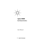
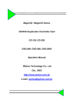
Air Flow and Atomizing Pressure
NOTE: All tests were completed with the 0.055 in. (1.397 mm) nozzle, large pattern air cap, and the pattern adjustment valve fully open.
Air Flow
Atomizing Air Pressure
(inlet pressure versus atomizing pressure)
35
20
NOMINAL ATOMIZING PRESSURE (psi)
30
AIR FLOW (scfm)
25
20
15
10
5
0
10
18
16
14
12
10
8
6
4
2
20
30
40
50
GUN INLET PRESSURE (psi)
60
70
0
10
20
30
40
50
60
70
GUN INLET PRESSURE (psi)
6
308741
Gun Inlet Pressure
psi (kPa, bar)
Nominal Atomizing Pressure
psi (kPa, bar)
10 (70, 0.7)
1 (7, 0.1)
20 (140, 1.4)
4 (28, 0.2)
30 (210, 2.1)
7 (48, 0.4)
40 (280, 2.8)
10 (70, 0.7)
50 (345, 3.4)
13 (91, 0.9)
60 (410, 4.1)
16 (111, 1.1)
70 (480, 4.8)
19 (132, 1.3)
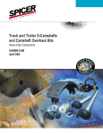
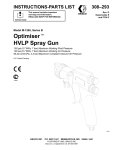
Typical Installation
E
F
G
H
A
B
C
KEY
A
B
C
D
E
F
G
H
Delta Spray Gun
See page 4 for gun part numbers.
Fluid Inlet; 3/8 npsm (R3/8–19)
Air Swivel Inlet; 1/4 npsm (R1/4–19)
Air Hose
Recommend 5/16” (7.9 mm) ID hose
Optional 3/8” (9.5 mm) ID hose
Air Shut-off Valve
Air Regulator
Air Filter
Air Supply Line
The Delta Spray HVLP spray gun was designed to
produce the highest quality finish with today’s fluids as
well as the Low V.O.C. (volatile organic compound)
fluids of tomorrow.
This spray gun can spray most coatings or finishes
currently being used for automotive, industrial, aerospace, marine, wood, plastic and architectural applications, while easily operating from any paint delivery
system, including cups, pressure pots, or remote
pumps for production line operation.
The spray gun typically utilizes 40 psi (280 kPa, 2.8
bar) inbound air pressure to produce high quality paint
finishes at 10 psi (70 kPa, 0.7 bar) atomizing air pressure.
D
07600A
Ventilate the Spray Booth
WARNING
To prevent hazardous concentrations of
toxic and/or flammable vapors, spray
only in a properly ventilated spray booth.
Do not operate the spray gun unless
ventilation fans are operating.
Check and follow all of the National,
State and Local codes regarding air exhaust velocity requirements.
Check and follow all local safety and fire codes.
The air regulator must have a minimum air flow
capacity of 30 scfm at 100 psi (0.7 MPa, 7 bar) air
pressure. Refer to the Pressure Drop Charts, page
11.
308741
7
Setup
1. Connect the Air Line
2. Connect the Fluid Hose
NOTE:
NOTE:
D You must install an air pressure regulator (F) on the
gun air line to control air pressure to the gun. See
Fig. 2.
D Before connecting the fluid line, blow it out with air
and flush it with solvent. Use solvent which is
compatible with the fluid to be sprayed.
D If your regulated air source does not have a filter,
install an air filter (G) on the air line to ensure a dry,
clean air supply to the gun. Dirt and moisture can
ruin the appearance of your finished workpiece.
See Fig. 2.
D Install a fluid regulator (L) on the fluid line to control
fluid pressure to the gun. See Fig. 4.
D Use a 5/16 inch (7.9 mm) I.D. air hose to minimize
excessive pressure drop in the hose. See the
Pressure Drop Chart on page 11 for the expected
pressure drops through a 25 ft. (7.625 m) hose.
D Filter the fluid line of coarse particles and sediment
to avoid clogging the fluid nozzle and causing
finishing defects.
A. Connect the fluid hose (J) to the gun fluid inlet (B)
3/8–18 npsm [R 3/8–19] compound thread.
A. Connect the air hose (D) to the 1/4 npsm gun air
inlet (C).
B
J
C
7034A
Fig. 3
D
7033A
Fig. 1
B. Connect the other end of the air hose (D) to a regulated air supply line (H).
B. Connect the other end of the fluid hose (J) to a
regulated fluid supply line (K).
NOTE: Fig. 4 shows the fluid regulator (L) and
fluid shut-off valve (M) on the fluid supply line (K).
NOTE: Fig. 2 shows the filter (G) air regulator (F),
and air shut-off valve (E) on the air supply line.
H
K
G
F
L
M
J
E
01990
Fig. 2
8
D
308741
Fig. 4
7016A
Setup
3. Flush the Spray Gun.
6. Adjust the Spray Pattern
Before putting any paint through the spray gun, flush
the gun out with a solvent that is compatible with the
fluid to be sprayed, using the lowest possible fluid
pressure and a grounded metal container.
WARNING
COMPONENT RUPTURE HAZARD
Do not exceed the 100 psi (0.7 MPa,
7 bar) maximum fluid and air pressure of this gun. Higher pressures can cause parts
to rupture and result in serious injury.
Follow these steps to establish the correct fluid flow
and air flow:
7035A
Fig. 5
A. Turn the fluid adjustment knob (21) counterclockwise until no restriction of the trigger movement is
felt, then turn out another half turn. When the knob
is turned far enough, the trigger should be able to
touch the gun handle when the gun is triggered.
WARNING
PRESSURIZED EQUIPMENT HAZARD
To reduce the risk of a serious injury whenever you
are instructed to relieve pressure, follow the Pressure Relief Procedure on page 12.
WARNING
PRESSURIZED EQUIPMENT HAZARD
To avoid injury, never open the fluid adjustment
knob (21) beyond the one half turn indicated in
Adjust the Spray Pattern.
4. Relieve the Pressure.
5. Position the Air Cap
Rotate the air cap as needed to achieve the desired
spray pattern direction. To create a round pattern, turn
the pattern air off by turning the pattern adjustment
knob (13a) fully clockwise. Refer to Fig. 12, page 11.
21
open
Vertical Pattern
7036A
Fig. 7
Horizontal Pattern
Fig. 6
02020
308741
9
Setup
6. Adjust the Spray Pattern (continued)
B. Adjust the fluid flow using the fluid pressure
regulator (L) installed in the gun fluid line. Typical
industrial flow rates will vary with regulator pressures from 5 to 30 psi (34 to 210 kPa, 0.3 to
2.1 bar).
NOTE: A larger fluid nozzle at a reduced fluid pressure
will maintain the same flow rate, but slow down the
fluid stream (velocity). When air is applied, this allows
the air to act on the fluid longer and improve the atomization.
D. If further fluid flow restriction is needed at the gun,
turn the fluid adjustment knob (21) clockwise to
reduce the volume of fluid output by limiting the
needle travel.
L
21
7019A
Fig. 8
close
C. Hold the gun parallel to the floor and adjust the fluid
pressure to yield a 1 to 6 inch (25.4 to 152.4 mm)
straight fluid stream before the stream falls off.
7039A
Fig. 11
1–6 in.
(25.4–152.4 mm)
straight fluid stream
WARNING
7037A
Fig. 9
Fluid Velocity of Fluid Nozzles
at the Same Flow Rate
PRESSURIZED EQUIPMENT HAZARD
To avoid injury, never open the fluid adjustment
knob (21) beyond the one half turn indicated in
Adjust the Spray Pattern, page 9.
CAUTION
Restricting the trigger and fluid needle travel by
continuously spraying with the fluid adjustment knob
closed (turned clockwise), will cause accelerated
abrasive wear on the fluid needle and wear on the
trigger/air valve shaft interface.
0.042
0.055
0.070
0.086
(1.067) (1.397) (1.778)
(2.184)
Orifice Size in inches (mm)
7038A
Fig. 10
10
0.110
(2.794)
308741
For the best results, use the gun fluid regulator to
adjust the fluid flow or use a different size needle/
nozzle/air cap combination.
Setup
6. Adjust the Spray Pattern (continued)
NOTE:
D If the fluid adjustment knob is turned in all the way
the gun will emit only air.
D For continuous spraying, turn the fluid adjustment
knob (8) counterclockwise until no restriction of the
trigger movement is felt. When the knob is turned
out far enough, the trigger should be able to touch
the gun handle when the gun is triggered. For the
typical fluid adjustment knob setting, turn the knob
out 1/2 turn more. This setting provides maximum
fluid flow and prevents premature wear on the fluid
nozzle.
E. Open the pattern adjustment valve (25) by turning
the knob fully counterclockwise to achieve a full
fan pattern.
F
Pressure Drop Chart
5/16 inch (7.9 mm) I.D. hose
Recommended hose size to minimize excessive
pressure drop. Expected pressure drops measured
using 25 ft. (7.625 m) long hose, with gun triggered.
25
Close
(narrower
pattern)
01997
Fig. 13
Open
(wider
pattern)
Air Regulator Pressure
Setting
psi (kPa, bar)
Gun Inlet Pressure
18.5 (128, 1.3)
10 (70, 0.7)
34.0 (238, 2.3)
20 (140, 1.4)
48.0 (335, 3.3)
30 (210, 2.1)
62.5 (427, 4.3)
40 (280, 2.8)
76.5 (525, 5.3)
50 (345, 3.4)
90.5 (624, 6.3)
60 (410, 4.1)
psi (kPa, bar)
G. Test the spray pattern and atomization while holding the gun about 6 to 8 inches (150 to 200 mm)
from the test piece.
Fig. 12
7040A
F. Using the air pressure regulator (F), set the air
supply pressure at about 50 psi (345 kPa, 3.4 bar).
See the Pressure Drop Chart for regulator setting
versus gun inlet pressure comparison.
H. If the spray pattern is too wide with the pattern
adjustment knob (13a) turned fully counterclockwise, turn the pattern adjustment knob clockwise
until you have the desired pattern size.
NOTE: Turning the pattern adjustment knob fully
clockwise will produce a round pattern.
I.
If available, use the fluid manufacturer’s recommendations to set the air line pressure for a high
volume, low pressure, spray gun application.
NOTE: Local laws may limit the maximum pressure to 10 psi (70 kPa, 0.7 bar) at the air cap for
HVLP compliance. The accessory Air Cap Verification Kit is available to measure the atomizing pressure at the air cap.
Check the atomization quality again. Increase the
gun air supply pressure with the air pressure regulator in 5 psi (34 kPa, 0.3 bar) increments until you
obtain the desired atomization.
J. If after increasing the gun air supply pressure the
atomization is still unacceptable, try installing a
larger fluid nozzle size to reduce the fluid velocity.
Refer to Fig. 10. Repeat steps 6-E to 6-I until you
obtain the desired atomization.
308741
11
Operation
Pressure Relief Procedure
WARNING
PRESSURIZED EQUIPMENT HAZARD
The system pressure must be manually relieved to
prevent the system from starting or spraying accidentally. To reduce the risk of an injury from accidental spray from the gun, splashing fluid, or
moving parts, follow the Pressure Relief Procedure whenever you:
D
D
D
D
are instructed to relieve the pressure,
stop spraying,
check or service any of the system equipment,
or install or clean the spray nozzle.
1. Turn off the air and fluid supply to the gun.
2. Trigger the gun into a grounded metal waste
container to relieve air and fluid pressure.
Applying the Fluid
When using the HVLP spray gun, instead of a conventional air spray gun, you may need to use a slightly
slower hand movement and make fewer passes with
the gun to coat a part. This is due to the reduced spray
velocity produced by lower HVLP air pressures, along
with a larger fluid particle size because there is less air
to blow off solvents than what is produced by conventional air spray. Take care to avoid runs or sags as you
spray.
1. To achieve the best results when applying fluid,
keep the gun perpendicular to the surface and
maintain a consistent distance of approximately 6
to 8 inches (150 to 200 mm) from the object being
sprayed. See Fig. 14.
2. To obtain an even finish, use smooth, even strokes
across the object being sprayed with 50% overlap.
3. Paint using parallel strokes. This spray gun applies
all coatings evenly without cross coating.
WRONG
07930
Fig. 14
12
RIGHT
308741
Daily Gun Care, Flushing, and Cleaning
WARNING
CAUTION
PRESSURIZED EQUIPMENT HAZARD
To reduce the risk of a serious injury whenever you
are instructed to relieve pressure, follow the Pressure Relief Procedure on page 12.
Clean all parts with a non-conductive solvent, compatible with the fluid being sprayed. Conductive
solvents can cause the gun to malfunction.
Methylene chloride with formic or propionic acid is
not recommended as a flushing or cleaning solvent
with this gun as it will damage aluminum and nylon
components.
CAUTION
Solvent left in gun air passages could result in a poor quality paint finish. Do not use any cleaning method which
may allow solvent into the gun air passages.
Do not point the gun up while cleaning it.
07042A
Do not immerse the gun in solvent.
07041A
Do not wipe the gun with a cloth soaked in
solvent; ring out the excess.
02027
Do not use metal tools to clean the air cap
holes as this may scratch them; scratches can
distort the spray pattern.
02055
General System Maintenance
1. Relieve the pressure.
2. Clean the fluid and air line filters daily.
4. Flush the gun before changing colors and whenever you are done operating the gun.
3. Check for any fluid leakage from the gun and fluid
hoses. Tighten fittings or replace equipment as
needed.
308741
13
Daily Gun Care, Flushing, and Cleaning
4. Point the gun down into a grounded metal container, and flush the gun with solvent until all traces
of paint are removed from the gun passages.
WARNING
PRESSURIZED EQUIPMENT HAZARD
To reduce the risk of a serious injury whenever you
are instructed to relieve pressure, follow the Pressure Relief Procedure on page 12.
1. Relieve the pressure.
2. Disconnect the fluid supply hose (J) and air supply
hose (D) from the gun.
7035A
Fig. 17
D
J
5. Turn off the solvent supply.
6. Relieve the pressure. Disconnect the solvent
supply.
7044A
Fig. 15
7. Disconnect the solvent (N) supply hose from the
gun.
3. Connect the solvent supply hose (N) to the gun.
N
N
7109A
Fig. 16
14
308741
Fig. 18
7044A
Daily Gun Care, Flushing, and Cleaning
8. Remove the air cap retaining ring (15) and air cap
(14).
12. With the gun pointed down, clean the front of the
gun, using the soft-bristle brush and solvent.
9. Trigger the gun while you remove the fluid nozzle
(12) from the gun with the gun tool (28).
12
28
14, 15
7045A
Fig. 19
7046A
Fig. 21
CAUTION
Trigger the gun whenever you tighten or remove the
nozzle. This keeps the needle seat away from the
nozzle seating surface and prevents the seat from
being damaged.
10. Clean the air cap retaining ring, air cap, and fluid
nozzle with solvent.
13. Scrub the air cap retaining ring, air cap, and fluid
nozzle with the soft-bristle brush. To clean out air
cap holes, use a soft implement, such as a toothpick, to avoid damaging critical surfaces. Clean the
air cap and fluid nozzle daily, minimum. Some
applications require more frequent cleaning. Do
not soak the air cap retaining ring in solvent for
prolonged periods of time.
11. Dip the end of a soft-bristle brush into a compatible
solvent. Do not continuously soak the brush’s
bristles with solvent and do not use a wire brush.
Fig. 20
02007
02011
Fig. 22
308741
15
Daily Gun Care, Flushing, and Cleaning
14. Trigger the gun while you install the fluid nozzle
(12) with the gun tool (28). Tighten the nozzle
securely to 125–135 in-lb (14–15 NSm) to obtain a
good seal.
15. Install the air cap retaining ring (15) and air
cap (14).
12
17. After cleaning the gun, lubricate the following parts
with lubricant 111265 daily:
D
Fluid adjustment knob threads
D
Trigger pivot pin
D
Fluid needle shaft
1
Lubricate
28
14, 15
1
Torque to 125–135 in-lb (14–15 NSm)
7045A
Fig. 23
16. Dampen a soft cloth with solvent and wring-out the
excess. Point the gun down and wipe off the
outside of the gun.
Lubricate
Fig. 25
7047A
Fig. 24
16
308741
07032A
Troubleshooting
WARNING
PRESSURIZED EQUIPMENT HAZARD
To reduce the risk of a serious injury, follow the Pressure Relief Procedure on page 12 before checking
or repairing any part of the gun or system.
PROBLEM
Fluid flow is fluttering while spraying
CAUSE
SOLUTION
1. Fluid nozzle not tight enough
1. Tighten fluid nozzle to 125–135
in-lb (14–15 NSm).
2. Fluid filter clogged
3. Check fluid filter.
4. Fluid adjustment knob not properly set
5. Turn the fluid adjustment knob
out for less feathering or use a
larger size nozzle.
1. Air hose size is too restricted for
higher air flow being used
1. Use 5/16 in. (7.9 mm) I.D. air
hose if the hose is 25 ft.
(7.625 m) long. If longer hose is
needed, use a 3/8 in. (9.5 mm)
I.D. hose.
2. Fluid pressure too low, causing
fluid flow to reduce when gun is
elevated
3. Raise fluid pressure at source or
use a smaller fluid nozzle.
Pattern becomes off-set or heavy on
ends
Air cap horn holes plugged or damaged
Clean air cap horn holes with nonmetallic item such as a toothpick, or
replace air cap.
Gun fluid pressure is too high with
gun triggered
Using needle/nozzle kit with too
small orifice
Use needle/nozzle kit with larger
orifice
Using a low fluid pressure setting,
the fluid flow is too high, making it
necessary to restrict needle travel to
reduce fluid flow
Using needle/nozzle kit with too
large orifice
Use needle/nozzle kit with smaller
orifice
Fluid system will not operate at low
enough fluid pressure [below 10 psi
(70 kPa, 0.7 bar)]
There is no fluid regulator, or air
regulator on pressure pot is not sensitive enough at low pressures
Add low pressure fluid regulator, or
add more sensitive low pressure air
regulator on pressure pot.
Fluid flow fades while spraying high
viscosity fluids
308741
17
Service
Items Needed for Service
12
D
D
D
D
D
Gun Tool – provided
Packing Installation Tool – provided
Adjustable Wrench
Screw Driver
Lubricant part no. 111265; see Accessories, page
28, to order
D Compatible Solvent
28
14, 15
Fluid Packings Replacement
WARNING
PRESSURIZED EQUIPMENT HAZARD
To reduce the risk of a serious injury, follow the
Pressure Relief Procedure on page 12 before
checking or repairing any part of the gun or system.
NOTE:
D Order Fluid Packing Kit 239640. The kit includes
the spreader, u-cup, and spacer.
D Clean parts with a solvent that is compatible with
the parts and the fluid being sprayed.
D Lightly lubricate the parts indicated in Fig. 28 with
lubricant 111265.
7028A
Fig. 26
4. Remove the fluid adjustment knob (21) and fluid
spring (23). See Fig. 28.
5. Pull the fluid needle (13) out the back of the gun.
6. Remove the screw (11), pin (17), and trigger (10).
7. Remove the hex nut (9) with the gun tool (28).
1. Relieve the pressure.
8. Remove the spray housing (2a) and insert (4).
2. Remove the air cap retaining ring (15) and air cap
(14). See Fig. 26.
3. Trigger the gun while you remove the fluid nozzle
(12) with the gun tool (28).
CAUTION
Trigger the gun whenever you tighten or remove the
nozzle. This keeps the needle seat away from the
nozzle seating surface and prevents the seat from
being scratched.
18
308741
9. Unscrew the packing screw (8) from the insert (4)
with the gun tool (28).
10. Use the back end of the fluid needle (13) to push
the three fluid packings (5) out of the insert (4). Be
careful not to damage the needle or insert. Discard
the old fluid packings.
11. Check the fluid needle (13) for damage or excessive wear. Replace needle tip or entire needle if
necessary.
Service
12. Place the new fluid packings (5) and packing
screw (8) onto the needle (13). See Fig. 27 for the
orientation of the parts.
20. To avoid galling of the fluid nozzle seat in the insert
(4), apply a thin film of lubricant to the seat. Trigger
the gun while you install the fluid nozzle (12) with
the gun tool (28). Torque the nozzle securely to
145–155 in-lb (16–17 NSm).
13. Insert the fluid needle (13) into the back of the
insert (4) to install the fluid packings (5).
21. Tighten the hex nut (9) securely to 125–135 in-lb
(14–15 NSm).
14. Tighten the packing screw (8) just enough to hold
the packings (5) in the insert (4). The needle (13)
must move freely. Remove the needle.
NOTE: To ensure proper alignment of the parts, follow
the next steps in the order they are given.
4
1
15. Slide the insert (4) into the spray housing (2a). See
Fig. 28. Align the housing with the slot and lip (A)
on the gun and slide the insert into the gun
body (1).
2
3
16. Tighten the hex nut (9) onto the insert (4) handtight, then loosen the nut about one turn so the
insert (4) and spray housing sit loosely in the gun
body.
5
17. Lubricate and install the fluid needle (13).
13
18. Lubricate the fluid adjustment knob threads (21),
and install the fluid spring (23) and adjustment
knob.
2
12
14
Spreader; tapered end down
2
U-cup; lips face up
3
Spacer
02024
25c
25a
6
*25b
25d
7
1
13
15
1
4
1
Item 2 includes 2a–2b
Item 13 includes item 13a
Item 25 includes 25a–25d
13a
1
11
1
Fig. 27
19. Install the trigger (10), pin (17), and screw (11).
Torque the screw to 20–30 in-lb (2.3–3.4 NSm).
3
8
26*
16*
5
21
4
19
20*
22
23
A
*2b
24
3
2a
17
*5
8
9
3
10
1
6
2
3
1
Lightly lubricate
2
Lightly lubricate threads
3
Torque to 125–135 in-lb (14–15 NSm)
4
Torque to 20–30 in-lb (2.3–3.4 NSm)
5
U-cup lips face air valve assembly (26)
6
U-cup lips face away from nut (19/25a)
7
Torque to 145–155 in-lb (16–17 NSm)
*Parts included in Repair Kit 239–639
7584A
Fig. 28
308741
19
Service
22. To tighten the packing screw (8), turn the screw in
until it touches the fluid packings (5), then tighten
one full turn to pre-set the packings. Loosen the
screw, then turn it in until it touches the packings
again. Tighten the screw 1/12 turn more (equal to
half the distance between points on the hex head).
23. Trigger the gun to test the needle movement. If the
needle does not return after the trigger is released
or is slow in returning, loosen the packing screw
(8) slightly until the needle returns freely.
24. Install the air cap (14) and air cap retaining ring
(15). Hand-tighten the ring.
25. Make sure the gun fluid packings are sealing
properly by spraying solvent at low pressure
before fully pressurizing the gun with the fluid to be
sprayed.
If the fluid packings leak, tighten the packing screw
(8) slightly and retest until the packings and needle
seal completely.
Complete Gun Packing Replacement
WARNING
PRESSURIZED EQUIPMENT HAZARD
To reduce the risk of a serious injury, follow the
Pressure Relief Procedure on page 12 before
checking or repairing any part of the gun or system.
NOTE:
D Gun Repair Kit 239639 is available. The kit includes
an o-ring (2b), fluid packing kit (5), u-cups (16, 20,
25b), and air valve assembly (26).
D Clean parts with a solvent that is compatible with
the parts and the fluid being sprayed.
D Lightly lubricate the parts indicated in Fig. 28 with
lubricant 111265.
20
308741
1. Relieve the pressure.
2. Remove the air cap retaining ring (15) and air cap
(14). See Fig. 26, page 18.
3. Trigger the gun while you remove the fluid nozzle
(12) with the gun tool (28).
CAUTION
Trigger the gun whenever you tighten or remove the
nozzle. This keeps the needle seat away from the
nozzle seating surface and prevents the seat from
being scratched.
4. Remove the fluid adjustment knob (21) and fluid
spring (23). See Fig. 28, page 19.
5. Pull the fluid needle (13) out the back of the gun.
6. Remove the screw (11), pin (17), and trigger (10).
7. Remove the hex nut (9) with the gun tool (28).
8. Remove the spray housing (2a) and insert (4).
Remove the o-ring (2b) with a pick and install the
new o-ring.
To ease o-ring installation, place the insert (4) into
the spray housing (2a) to plug the end. Install one
end of the o-ring into the groove in the housing,
then press the rest of the o-ring into place.
9. Unscrew the packing screw (8) from the insert (4)
with the gun tool (28).
10. Use the back end of the fluid needle (13) to push
the three fluid packings (5) out of the insert (4). Be
careful not to damage the needle or insert. Discard
the old fluid packings.
Service
11. Place the new fluid packings (5) and packing
screw (8) onto the needle (13). See Fig. 27, page
19, for the orientation of the parts.
12. Insert the fluid needle (13) into the back of the
insert (4) to install the fluid packings (5).
13. Tighten the packing screw (8) just enough to hold
the packings (5) in the insert (4). The needle (13)
must move freely. Remove the needle.
25. Install the new u-cup seal (20) with the seal installation tool (29); the u-cup lips must face toward the
tool as shown in Fig. 31. This will help apply even
pressure to the u-cup lips and avoid damaging
them.
26. Push the u-cup seal (20) into the fluid valve nut
(19) until a definite snap is felt.
14. Unscrew the pattern adjustment valve assembly
(25).
13
15. Remove the retaining ring (25d) and unscrew the
pattern adjustment valve (25c).
16. Remove the u-cup seals (25b) from the pattern
adjustment nut (25a). Be careful not to damage
the seal surface or the nut’s internal threads.
17. One at a time, install the new u-cup seals (25b)
with the seal installation tool (29); the u-cup lips
must face toward the tool as shown in Fig. 31.
Fig. 29
18. Push each u-cup seal (25b) into the pattern adjustment nut (25a) until a definite snap is felt.
1
16
19. Lubricate the pattern adjustment valve (25c)
threads and install the valve into the nut (25a).
Install the retaining ring (25d), then back out the
pattern adjustment valve as far as the retaining
ring allows it to go.
U-cup lips face the tool
1
29
20. Remove the fluid valve nut (19), air valve spring
(22), and air valve assembly (26). Discard the air
valve assembly. See Fig. 28, page 19.
21. Remove the u-cup (16) from the gun body. The
threaded end of the needle (13) can be used to
push out the u-cup. Be careful not to damage
needle or sealing surface. See Fig. 29.
22. Place the new u-cup (16) on the seal installation
tool (29), with the u-cup lips facing the tool as
shown in Fig. 30.
Fig. 30
1
U-cup lips face
the tool
20 or 25b
23. Push the packing (16) into the back of the gun until
a definite snap is felt.
24. Remove the u-cup seal (20) from the fluid valve nut
(19). Be careful not to damage the seal surface or the
nut’s internal threads.
29
1
19 or 25a
Fig. 31
308741
21
Service
NOTE: To ensure proper alignment of the parts, follow
the next steps in the order they are given.
33. Install the needle spring (23) and fluid adjustment
knob (21).
27. Slide the insert (4) into the spray housing (2a), and
install them onto the gun body (1). Align the housing with the slot and lip (A) on the gun body (1).
34. Install the trigger (10), pivot pin (17), and screw
(11). Torque the screw to 20–30 in-lb (2.3–3.4
NSm).
28. Tighten the hex nut (9) onto the insert (4) handtight, then loosen the nut about one turn so the
insert (4) and spray housing sit loosely in the gun
body.
29. Check the fluid needle (13) for damage or excessive wear. Replace needle tip or entire needle if
necessary.
30. Lubricate the outside of the new air valve assembly (26) and place it on the fluid needle (13),
against the nut (B). See Fig. 32. This helps align
the entrance of the air valve stem into the inside
diameter of the u-cup (16) without damaging the
u-cup lip.
31. Install the fluid needle (13) and the air valve
assembly (26) into the back of the gun.
13
26
B
35. To avoid galling of the fluid nozzle seat in the insert
(4), apply a thin film of lubricant to the seat. Trigger
the gun while you install the fluid nozzle (12) with
the gun tool (28). Torque the nozzle securely to
145–155 in-lb (16–17 NSm).
36. Tighten the hex nut (9) securely to 125–135 in-lb
(14–15 NSm).
37. Install the pattern adjustment valve assembly (25).
Torque the nut (25a) to 125–135 in-lb (14–15
NSm).
38. To tighten the packing screw (8), turn the screw in
until it touches the fluid packings (5), then tighten
one full turn to pre-set the packings. Loosen the
screw, then turn it in until it touches the packings
again. Tighten the screw 1/12 turn more (equal to
half the distance between points on the hex head).
39. Trigger the gun to test the needle movement. If the
needle does not return after the trigger is released
or is slow in returning, loosen the packing screw
(8) until the needle returns freely.
40. Install the air cap (14) and air cap retaining ring
(15). Hand-tighten the ring.
41. Make sure the gun fluid packings are sealing
properly by spraying solvent at low pressure
before fully pressurizing the gun with the fluid to be
sprayed.
Fig. 32
32. Install the air valve spring (22). Point the gun down
to center the spring (22) and tighten the fluid nut
(19) to 125–135 in-lb (14–15 NSm).
22
308741
If the fluid packings leak, tighten the packing screw
(8) slightly and retest until the packings and fluid
needle seal completely.
Notes
308741
23
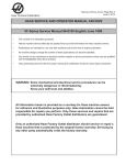
Parts
Item 2 includes 2a–2b
Item 13 includes item 13a
Item 25 includes 25a–25d
25c
25a
25b
12
25d
14
13
13a
26
1
15
16
11
21
4
19
20
22
23
24
2b
2a
9
8
17
10
5
7586A
29
24
308741
28
Parts
Part No. 239559 to 239567
Pressure Feed HVLP Spray Gun Assembly
Ref.
No.
Part No.
Description
1
239721
BODY, gun
2
239651
2a
Qty.
Ref.
No.
Part No.
Description
Qty.
1
19
192355
NUT, fluid valve
1
SPRAY HOUSING ASSY.;
Includes items 2a–2b
1
20*
110453
U-CUP
1
S HOUSING, spray; not
sold separately
21
192266
KNOB, fluid adjustment
1
1
22
114069
SPRING, air valve
1
SPRING, needle
1
2b*
111316
S O-RING, CV75
1
23l
4
191849
INSERT, fluid
1
24
239655
SWIVEL, air
1
5*
239640
KIT, fluid packing; Includes
spreader, u-cup, and spacer
1
25
239653
1
8
192352
SCREW, packing
1
PATTERN ADJUSTMENT
VALVE ASSY.; Includes
items 25a–25d
9
192348
NUT, hex; 1/2–20 UNF
1
25a
192356
S NUT, pattern adjustment
1
10
192271
TRIGGER
1
25b*
110453
S U-CUP
2
11
203953
SCREW, trigger lock
1
25c
192353
S VALVE, pattern adjustment, HVLP
1
12l
NOZZLE, fluid
1
25d
114068
S RING, retaining
1
13l
NEEDLE ASSY.; Includes
replaceable item 13a
1
26*
240823
AIR VALVE ASSY.
1
13al
S TIP, needle
1
28
192281
TOOL, gun
1
14l
AIR CAP
1
29
192282
TOOL, packing installation
1
15
192276
RING, air cap retaining
1
16*
188493
U-CUP
1
17
192272
PIN, pivot
1
Gun
Part No.
Needle/
Nozzle Kit
Item 12
Nozzle
Includes
items 12–13
Item 13
Needle
Assy.
l See chart for part number.
*
These parts are included in Repair Kit 239639,
which may be purchased separately.
Item 13a
Needle
Tip
Item 14
Air Cap
Item 23
Spring
Orifice
Size
in. (mm)
Fluid
Supply
Includes
item 13a
239559
239600
192295
239643
192304
192321
114072
.030 (.762)
Pressure
239560
239601
192296
239644
192305
192321
114072
.042 (1.067)
Pressure
239561
239602
192297
239645
192306
192321
114072
.055 (1.397)
Pressure
239562
239603
192298
239646
192307
192322
114072
.070 (1.778)
Pressure
239563
239604
192299
239647
192308
192322
114072
.086 (2.184)
Pressure
239564
239605
192300
239648
192309
192323
114072
.110 (2.794)
Pressure
239565**
239606
192301
239649
192310
192321
110402
.042 (1.067)
Pressure
239566**
239607
192302
239650
192311
192321
110402
.055 (1.397)
Pressure
239567**
239598
192293
239641
192312
192322
110402
.070 (1.778)
Pressure
** These guns have a stainless steel needle tip, which is not recommended except for applications where it is
necessary.
308741
25
Parts
Item 2 includes 2a–2b
Item 13 includes item 13a
Item 25 includes 25a–25d
25c
25a
25b
12
25d
14
13
13a
26
1
15
16
11
21
19
20
22
23
4
2b
24
2a
9
8
10
5
29
26
308741
17
28
7585A
Parts
Part No. 239574 and 239575
Gravity Feed HVLP Spray Gun Assembly
Ref.
No.
Part No.
Description
1
239721
BODY, gun
2
239799
2a
Qty.
Ref.
No.
Part No.
Description
Qty.
1
19
192355
NUT, fluid valve
1
SPRAY HOUSING ASSY.;
Includes items 2a–2b
1
20*
110453
U-CUP
1
S HOUSING, spray, gravity;
not sold separately
21
192266
KNOB, fluid adjustment
1
1
22
114069
SPRING, air valve
1
2b*
111316
S O-RING, CV75
1
23
114072
SPRING, needle
1
4
191850
INSERT, fluid, gravity
1
24
239655
SWIVEL, air
1
5*
239640
KIT, fluid packing; Includes
spreader, u-cup, and spacer
1
25
239653
1
8
192352
SCREW, packing
1
PATTERN ADJUSTMENT
VALVE ASSY.; Includes
items 25a–25d
9
192348
NUT, hex; 1/2–20 UNF
1
25a
192356
S NUT, pattern adjustment
1
10
192271
TRIGGER
1
25b*
110453
S U-CUP
2
11
203953
SCREW, trigger lock
1
25c
192353
S VALVE, pattern adjustment
1
12l
NOZZLE, fluid
1
25d
114068
S RING, retaining
1
13l
NEEDLE ASSY.; Includes
replaceable item 13a
1
26*
240823
AIR VALVE ASSY.
1
13al
S TIP, needle
1
28
192281
TOOL, gun
1
29
192282
TOOL, packing installation
1
14
192329
AIR CAP
1
15
192276
RING, air cap retaining
1
16*
188493
U-CUP
1
17
192272
PIN, pivot
1
Gun
Part No.
Needle/
Nozzle Kit
Item 12
Nozzle
l See chart for part number.
*
These parts are included in Repair Kit 239639,
which may be purchased separately.
Item 13
Needle Assy.
Item 13a
Needle Tip
Orifice Size
in. (mm)
Fluid Supply
Includes
item 13a
Includes items
12–13
239574
239592
192287
239645
192306
.055 (1.397)
Gravity
239575
239593
192288
239646
192307
.070 (1.778)
Gravity
308741
27
Accessories
Cleaning Brush 105749
For use in cleaning gun
Lubricant 111265
One 4 oz. (113 gram) tube sanitary (non-silicone)
lubricant for fluid seals and wear areas.
Fluid Whip Hose Assembly 239622
100 psi (0.7 MPa, 7 bar) Maximum Working Pressure
Eases gun movement with increased hose flexibility.
4 ft. (1.22 m) long, 3/16 in. (4.76 mm) I.D.,
3/8 npsm(fbe), nylon with polyurethane cover
Whip Hose Parts Breakdown
Part No.
Description
239630
FITTING ASSY, male
239629
FITTING ASSY, swivel
061345
TUBING; 1000 ft. (305 m) roll
Fluid Hose Assembly
100 psi (0.7 MPa, 7 bar) Maximum Working Pressure
3/16 in. (4.76 mm) I.D., 3/8 npsm(fbe), nylon with
polyurethane cover
Air Hose Assembly 185353
100 psi (0.7 MPa, 7 bar) Maximum Working Pressure
Optional air hose for use when higher air flow is
required. 25 ft. (7.625 m) long, 3/8 in. (9.53 mm) I.D.,
1/4 npsm(f) swivel, buna-n
Air Control Valve Kit 243670
Install on the gun air inlet to control both the atomizing
air and the pressure in the spray gun cup (if used).
1/4 npsm x 1/4–19 BSPT.
Air Pressure Verification Kit
For use in checking air cap atomizing or pattern air
pressure at various supply air pressures. Not to be
used for actual spraying.
Install the kit air cap on the gun. Turn on the air to the
gun, then trigger the gun and read the air pressure on
the gauge.
NOTE: To be “HVLP compliant”, the atomizing air
pressure must not exceed 10 psi (70 kPa, 0.7 bar).
Part No.
Orifice
239609
0.030, 0.042, 0.055
(0.762, 1.067, 1.397)
239610
0.070, 0.086
(1.778, 2.184)
Part No.
Length
239611
0.110 (2.790)
239633
15 ft. (4.58 m)
239612
gravity
239634
25 ft. (7.63 m)
in. (mm)
Fluid Hose Parts Breakdown
Part No.
Description
239629
FITTING ASSY, swivel
061345
TUBING; 1000 ft. (305 m) roll
Air Hose Assembly
100 psi (0.7 MPa, 7 bar) Maximum Working Pressure
5/16 in. (7.94 mm) I.D., 1/4 npsm(f) swivel, nitrile
Part No.
Length
239636
15 ft. (4.58 m)
239637
25 ft. (7.63 m)
Air Whip Hose Assembly 239631
100 psi (0.7 MPa, 7 bar) Maximum Working Pressure
Eases gun movement with increased hose flexibility.
4 ft. (1.22 m) long, 5/16 in. (7.94 mm) I.D., 1/4 npsm(f)
swivel, nitrile
28
308741
7637A
Gun Air Regulator Assy. 235119
0–100 psi (0–0.7 MPa, 0–7 bar) air
regulator to control air pressure to
gun.
NOTE: Installing the gun air regulator adds a pressure drop that could
limit the air cap pressure.
7614A
Non–Swiveling Air Inlet Fitting 195065
Replaces the standard gun swivel fitting to prevent gun
from rotating during operation
Accessories
Gravity Cup
For use with gravity feed gun.
Nylon cup, 304 stainless steel 3/8
npsm(f) fluid inlet fitting, fluid filter
cartridge included.
7636A
Part No.
Size
239714
16 oz. (474 cc)
239715
8 oz. (237 cc)
SST Pressure Cup Kit 239803
with double air regulator
1 qt. (0.95 liter) capacity, 304 stainless steel cup. Includes a pressure
relief valve, a 0–100 psi (0–0.7 MPa,
0–7 bar) air regulator for gun
atomization, and a 0–15 psi (0–104
kPa, 0–1.0 bar) air regulator for the
1 qt. pressure cup supply air.
7612A
NOTE: Installing the pressure cup kit
adds a pressure drop that could limit
the air cap pressure.
Gravity Cup Holder Bracket 192407
Fits both gravity cup sizes.
Disposable Polyethylene Cup Liners
Paint and solvent resistant. 40 liners per box.
SST Pressure Cup Kit 239802
with single air regulator
1 qt. (0.95 liter) capacity, 304 stainless
steel cup. Includes a pressure relief
valve and a single air regulator and
gauge.
112490
112491
1 Quart Cup Size
2 Quart Cup Size
7611A
1 Quart Remote SST Pressure Cup 239804
1 qt. (0.95 liter) capacity, 304 stainless steel cup.
Includes air pressure regulator and gauge, 4 ft. (1.2 m)
length air and fluid hose with 1/4 npsm(f) swivel ends,
pressure relief valve, and rigid hook handle.
7623A
308741
29
Dimensions
Technical Data
6.7 in.
(170 mm)
7.6 in.
(193 mm)
7048A
Category
Data
Maximum Working Fluid
Pressure
100 psi (0.7 MPa, 7 bar)
Maximum Working Air
Pressure
100 psi (0.7 MPa, 7 bar)
Maximum Compliant
Inbound Air Pressure
40 psi (280 kPa, 2.8 bar)
Fluid and Air Operating
Temperature Range
32_ F to 140_ F (0_ C to 60_ C)
Weight
17.1 oz. (484 g)
Air Inlet
1/4–18 npsm (R1/4–19)
compound thread
Fluid Inlet
3/8–18 npsm (R3/8–19)
compound thread
Wetted Parts
304 and 17–4 PH Stainless
Steel, PEEK, Acetal, Ultra High
Molecular Weight Polyethylene
Noise Data*
Sound Pressure
Sound Power
*
30
308741
84.4 Db(A)
94.0 Db(A)
All readings were taken with the gun controls fully open
and with 40 psi (280 kPa, 2.8 bar). Sound pressure was
tested to CAGI–PNUEROP–1969. Sound power was
tested to ISO 3744–1981.
Notes
308741
31
Graco Standard Warranty
Graco warrants all equipment manufactured by Graco and bearing its name to be free from defects in material and workmanship on the
date of sale by an authorized Graco distributor to the original purchaser for use. With the exception of any special, extended, or limited
warranty published by Graco, Graco will, for a period of twelve months from the date of sale, repair or replace any part of the equipment
determined by Graco to be defective. This warranty applies only when the equipment is installed, operated and maintained in accordance with Graco’s written recommendations.
This warranty does not cover, and Graco shall not be liable for general wear and tear, or any malfunction, damage or wear caused by
faulty installation, misapplication, abrasion, corrosion, inadequate or improper maintenance, negligence, accident, tampering, or substitution of non–Graco component parts. Nor shall Graco be liable for malfunction, damage or wear caused by the incompatibility of
Graco equipment with structures, accessories, equipment or materials not supplied by Graco, or the improper design, manufacture,
installation, operation or maintenance of structures, accessories, equipment or materials not supplied by Graco.
This warranty is conditioned upon the prepaid return of the equipment claimed to be defective to an authorized Graco distributor for
verification of the claimed defect. If the claimed defect is verified, Graco will repair or replace free of charge any defective parts. The
equipment will be returned to the original purchaser transportation prepaid. If inspection of the equipment does not disclose any defect
in material or workmanship, repairs will be made at a reasonable charge, which charges may include the costs of parts, labor, and
transportation.
THIS WARRANTY IS EXCLUSIVE, AND IS IN LIEU OF ANY OTHER WARRANTIES, EXPRESS OR IMPLIED, INCLUDING BUT
NOT LIMITED TO WARRANTY OF MERCHANTABILITY OR WARRANTY OF FITNESS FOR A PARTICULAR PURPOSE.
Graco’s sole obligation and buyer’s sole remedy for any breach of warranty shall be as set forth above. The buyer agrees that no other
remedy (including, but not limited to, incidental or consequential damages for lost profits, lost sales, injury to person or property, or any
other incidental or consequential loss) shall be available. Any action for breach of warranty must be brought within two (2) years of the
date of sale.
Graco makes no warranty, and disclaims all implied warranties of merchantability and fitness for a particular purpose in connection
with accessories, equipment, materials or components sold but not manufactured by Graco. These items sold, but not manufactured
by Graco (such as electric motors, switches, hose, etc.), are subject to the warranty, if any, of their manufacturer. Graco will provide
purchaser with reasonable assistance in making any claim for breach of these warranties.
In no event will Graco be liable for indirect, incidental, special or consequential damages resulting from Graco supplying equipment
hereunder, or the furnishing, performance, or use of any products or other goods sold hereto, whether due to a breach of contract,
breach of warranty, the negligence of Graco, or otherwise.
FOR GRACO CANADA CUSTOMERS
The parties acknowledge that they have required that the present document, as well as all documents, notices and legal proceedings
entered into, given or instituted pursuant hereto or relating directly or indirectly hereto, be drawn up in English. Les parties reconnaissent avoir convenu que la rédaction du présente document sera en Anglais, ainsi que tous documents, avis et procédures judiciaires
exécutés, donnés ou intentés à la suite de ou en rapport, directement ou indirectement, avec les procedures concernées.
Graco Information
TO PLACE AN ORDER, contact your Graco distributor, or call one of the following numbers
to identify the distributor closest to you:
1–800–367–4023 Toll Free
612–623–6921
612–378–3505 Fax
All written and visual data contained in this document reflects the latest product information available at the time of publication.
Graco reserves the right to make changes at any time without notice.
Sales Office: Minneapolis
International Offices: Belgium, Korea, Hong Kong, Japan
www.graco.com
PRINTED IN USA 308741 08/1997, Revised 01/2004
32
308741