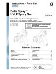
1
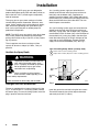
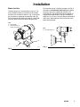
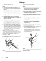
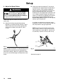
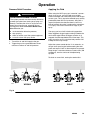
Instructions – Parts List
Automatic Delta Spray
HVLP Spray Guns
309030D
100 psi (0.7 MPa, 7 bar) Maximum Working Fluid Pressure
100 psi (0.7 MPa, 7 bar) Maximum Working Air Pressure
43 psi (300 kPa, 3.0 bar) Maximum Compliant Inbound Air Pressure
Read warnings and instructions.
Table of Contents
Symbols . . . . . . . . . . . . . . . . . . . . . . . . . . . . . . . . . . . . . . 2
Warnings . . . . . . . . . . . . . . . . . . . . . . . . . . . . . . . . . . . . . . 2
Selection Charts . . . . . . . . . . . . . . . . . . . . . . . . . . . . . . . 4
Air Flow and Atomizing Pressure . . . . . . . . . . . . . . . . . 5
Installation . . . . . . . . . . . . . . . . . . . . . . . . . . . . . . . . . . . . . 6
Setup . . . . . . . . . . . . . . . . . . . . . . . . . . . . . . . . . . . . . . . . . 8
Operation . . . . . . . . . . . . . . . . . . . . . . . . . . . . . . . . . . . . 13
Daily Gun Care, Flushing, and Cleaning . . . . . . . . . . 14
General Troubleshooting . . . . . . . . . . . . . . . . . . . . . . . 16
Spray Pattern Troubleshooting . . . . . . . . . . . . . . . . . . 19
Service . . . . . . . . . . . . . . . . . . . . . . . . . . . . . . . . . . . . . . 20
Parts . . . . . . . . . . . . . . . . . . . . . . . . . . . . . . . . . . . . . . . . 24
Accessories . . . . . . . . . . . . . . . . . . . . . . . . . . . . . . . . . . 28
Dimensions . . . . . . . . . . . . . . . . . . . . . . . . . . . . . . . . . . . 29
Mounting Hole Layout . . . . . . . . . . . . . . . . . . . . . . . . . . 29
Technical Data . . . . . . . . . . . . . . . . . . . . . . . . . . . . . . . . 30
Graco Standard Warranty . . . . . . . . . . . . . . . . . . . . . . 32
Graco Phone Number . . . . . . . . . . . . . . . . . . . . . . . . . . 32
GRACO INC.ąP.O. BOX 1441ąMINNEAPOLIS, MNą55440-1441
Copyright 1999, Graco Inc. is registered to I.S. EN ISO 9001
Part No. 241745 HVLP Spray Gun shown
mounted on Part No. 241697 Manifold.
Order the manifold separately from the
gun. See page 26 for part numbers.
Symbols
Warning Symbol
Caution Symbol
WARNING
CAUTION
This symbol alerts you to the possibility of serious
injury or death if you do not follow the instructions.
This symbol alerts you to the possibility of damage to
or destruction of equipment if you do not follow the
instructions.
WARNING
EQUIPMENT MISUSE HAZARD
INSTRUCTIONS
Equipment misuse can cause the equipment to rupture, malfunction or start unexpectedly and result in
serious injury.
This equipment is for professional use only.
Read all instruction manuals, tags, and labels before operating the equipment.
Use the equipment only for its intended purpose. If you are uncertain about usage, call your Graco
distributor.
Do not alter or modify this equipment. Use only genuine Graco parts and accessories.
Check equipment daily. Repair or replace worn or damaged parts immediately.
Use this equipment only in low pressure, air spray systems.
Do not exceed the maximum working pressure of the lowest rated system component. This equipment has a 100 psi (0.7 MPa, 7 bar) maximum working fluid and air pressure.
Route the hoses away from the traffic areas, sharp edges, moving parts, and hot surfaces. Do not
expose Graco hoses to temperatures above 180F (82C) or below –40F (–40C).
Wear hearing protection when operating this equipment.
Use fluids or solvents that are compatible with equipment wetted parts. See the Technical Data
section of all equipment manuals. Read the fluid and solvent manufacturer’s warnings.
Methylene Chloride with formic or propionic acid is not recommended as a flushing or cleaning
solvent with this gun or any other device with nylon or aluminum components as it can damage
these parts.
Comply with all applicable local, state and national fire, electrical and other safety regulations.
2
309030
WARNING
PRESSURIZED EQUIPMENT HAZARD
Spray from the gun, hose leaks or ruptured components can splash fluid in the eyes or on the skin and
cause serious injury.
Do not stop or deflect fluid leaks with your hand, body, glove or rag.
Follow the Pressure Relief Procedure on page 13 when: you are instructed to relieve pressure;
stop spraying; clean, check or service the equipment; and install or clean fluid nozzles.
Do not point the spray gun at anyone or at any part of the body.
Tighten all fluid connections before operating the equipment.
Check the hoses, tubes and couplings daily. Replace worn, damaged or loose parts immediately.
Permanently coupled hoses cannot be repaired; replace the entire hose.
FIRE AND EXPLOSION HAZARD
Poor air ventilation, open flames, or sparks can cause a hazardous condition and result in fire or
explosion and serious injury.
Provide fresh air ventilation to avoid the buildup of flammable fumes from solvent or the fluid being
sprayed.
Eliminate all ignition sources such as pilot lights, cigarettes and plastic drop cloths (static arc
hazard). Do not plug or unplug power cords or turn lights on or off in the spray area.
Electrically disconnect all equipment in the spray area.
Keep the spray area free of debris, including solvent, rags and gasoline.
Do not operate a gasoline engine in the spray area.
TOXIC FLUID HAZARD
Hazardous fluids or toxic fumes can cause serious injury or death if splashed in the eyes or on the
skin, inhaled, or swallowed.
Know the specific hazards of the fluid you are using. Read the fluid manufacturer’s warnings.
Store hazardous fluid in an approved container. Dispose of hazardous fluid according to all local,
state and national guidelines.
Dress appropriately for your application. Wear the appropriate protective clothing, gloves, eyewear,
and respirator.
309030
3
Selection Charts
TERMS:
Light Fluid:
Up to 18 seconds with No. 2 Zahn cup (20 centipoise)
Medium Fluid:
19 to 28 seconds with No. 2 Zahn cup (20–64 centipoise)
Heavy Fluid:
Greater than 28 seconds with No. 2 Zahn cup (greater than 64 centipoise) -2.8 Volatile Organic Compounds, High-solid Polyurethanes, Heavy Waterborne Enamels
HVLP Spray Gun Assemblies
Gun Assy.
Part No.
*
Includes:
Needle/
Nozzle Kit
Air Cap
Part No.
Part No.
Orifice Size
Pattern
Length
in. (mm)
in. (mm)
Material Usage:
Viscosity
Flow
oz./min. (l/min.)
241745
241769
195304
0.030 (0.762)
15 (381)
light
4–10 (0.12–0.30)
241746
241770
195304
0.042 (1.067)
16 (406)
light-medium
8–14 (0.24–0.42)
241747
241771
195304
0.055 (1.397)
16 (406)
medium
12–18 (0.36–0.54)
241748
241772
195305
0.070 (1.778)
17 (432)
medium-heavy
16–20 (0.48–0.60)
241751*
241775*
195304
0.042 (1.067)
16 (406)
light-medium
8–14 (0.24–0.42)
241752*
241776*
195304
0.055 (1.397)
16 (406)
medium
12–18 (0.36–0.54)
Stainless steel needle/tip
Measured with gun nozzle 10 in. (254 mm) from target surface
Selecting the Proper Needle/Nozzle Kit
For high flow rates or high viscosity fluid, select the
larger nozzle sizes.
The spray gun’s needle/nozzle kits range in size to
provide different fluid flow rates.
NOTE:
As a general guideline, use the fluid nozzle that will
give the required flow with the needle fully triggered at
the lowest fluid pressure.
For low flow rates or light viscosity fluid, select the
smaller nozzle sizes.
4
309030
To help select the proper needle/nozzle size, a fluid
pressure gauge may be connected temporarily to
the gun fluid inlet to determine the fluid pressure.
See Accessories, page 28.
See page 19 for troubleshooting information.
Air Flow and Atomizing Pressure
NOTE: All tests were completed with the 0.055 in. (1.397 mm) nozzle and Part No. 195304 Air Cap, and equivalent
gun inlet pressure applied to the atomization and fan ports (or fan adjustment valve fully open on manifold 243950).
Air Flow
Atomizing Air Pressure
(inlet pressure versus atomizing pressure)
Atomizing Air Flow
Fan Air Flow
22
NOMINAL ATOMIZING PRESSURE (psi)
Total Air Flow
40
35
AIR FLOW (scfm)
30
25
20
15
10
18
16
14
12
10
8
6
4
2
0
10
5
0
10
20
20
30
40
50
60
70
20
Total Air Flow
scfm (m/min)
40
50
60
70
80
GUN INLET PRESSURE (psi)
80
GUN INLET PRESSURE (psi)
30
Gun Inlet Pressure
psi (kPa, bar)
Nominal Atomizing Pressure
psi (kPa, bar)
10 (70, 0.7)
1.6 (11, 0.11)
20 (140, 1.4)
3.4 (24, 0.24)
Gun Inlet
Pressure
psi (kPa,
bar)
Atomizing
Air Flow
scfm (m/min)
Fan Air Flow
scfm (m/min)
10 (70, 0.7)
2.9 (0.08)
4.9 (0.14)
7.8 (0.22)
30 (210, 2.1)
5.9 (41, 0.41)
20 (140,
1.4)
5.5 (0.15)
6.4 (0.18)
11.9 (0.33)
40 (280, 2.8)
8.5 (60, 0.6)
50 (345, 3.4)
11.3 (80, 0.8)
30 (210,
2.1)
7.2 (0.20)
8.3 (0.23)
15.5 (0.43)
60 (410, 4.1)
14.5 (101, 1.01)
40 (280,
2.8)
8.9 (0.25)
10.5 (0.29)
19.4 (0.54)
70 (480, 4.8)
17.5 (123, 1.23)
80 (560, 5.6)
21 (147, 1.47)
50 (345,
3.4)
11.0 (0.31)
12.6 (0.35)
23.6 (0.66)
60 (410,
4.1)
13.0 (0.36)
14.9 (0.42)
27.9 (0.78)
70 (480,
4.8)
14.8 (0.41)
16.5 (0.46)
31.3 (0.88)
80 (560,
5.6)
16.8 (0.47)
19.1 (0.53)
35.9 (1.00)
309030
5
Installation
The Delta Spray HVLP spray gun was designed to
produce the highest quality finish with today’s fluids as
well as the Low V.O.C. (volatile organic compound)
fluids of tomorrow.
This spray gun can spray most coatings or finishes
currently being used for automotive, industrial, aerospace, marine, wood, plastic and architectural applications, while easily operating from paint delivery systems such as pressure pots or remote pumps for
production line operation.
NOTE: The HVLP spray gun typically uses 43 psi (300
kPa, 3.0 bar) inbound air pressure to produce high
quality paint finishes at 10 psi (70 kPa, 0.7 bar) atomizing air pressure.
The air regulator must have a minimum air flow
capacity of 30 scfm at 100 psi (0.7 MPa, 7 bar) air
pressure.
In a circulating system, apply anti-seize lubricant
222955 to the threads and mating faces of the manifold (101) and the elbows (107), supplied unassembled. Install the elbows (107) in both fluid ports of
the manifold (101). Connect the fluid supply line to one
elbow and the fluid return line to the other. The manifold fluid ports are reversible.
In a non-circulating system, apply anti-seize lubricant
222955 to the threads and mating faces of the manifold (101), a plug (109), and an elbow (107), supplied
unassembled. Install an elbow (107) in one fluid port of
the manifold (101), and a plug (109) in the other port.
Install the internal plug (5) in the gun fluid port on the
same side as the manifold plug. Connect the fluid
supply line to the manifold elbow (107). See Fig. 1.
Non–Circulating Setup Shown (cutaway view)
Ventilate the Spray Booth
1
Remove when used in circulating systems
2
Replace with an elbow (107) when used in circulating systems
WARNING
To prevent hazardous concentrations of
toxic and/or flammable vapors, spray
only in a properly ventilated spray booth.
Do not operate the spray gun unless
ventilation fans are operating.
Check and follow all of the National,
State and Local codes regarding air exhaust velocity requirements.
1
2
5
101
107
109
Check and follow all local safety and fire codes.
8587A
Fig. 1
Configure the Gun and Manifold
The gun is supplied with an internal fluid plug (5). See
Fig. 1. To use the gun in a circulating system, remove
the internal plug. In a non-circulating system, leave the
plug in place to minimize flush time.
6
309030
Install the gun on the manifold, using the four screws.
Thread the screws by hand, then torque alternately
and evenly to 65 in-lb (7.3 Nm).
Installation
Mount the Gun
To mount the gun on a reciprocating arm [0.5 in. (13
mm) diameter maximum], insert the bar (A) through
the hole in the manifold as shown in Fig. 2. Secure the
gun to the bar by tightening the mounting screw (B).
The tip of the gun should be 6 to 8 inches (150 to 200
mm) from the surface of the object being sprayed.
To mount the gun on a stationary support, see Fig. 3.
Also refer to the Mounting Hole Layout on page 29.
Attach the gun to the support with two M5 x 0.8
capscrews (C). The screws must be long enough to
engage the threaded holes in the gun manifold to a
depth of 1/4 in. (6 mm). The tip of the gun should be 6
to 8 inches (150 to 200 mm) from the surface of the
object being sprayed.
KEY
A
B
Mounting Bar
Mounting Screw (on
bottom of manifold)
KEY
C
M5 x 0.8 Capscrews
A
C
B
9417A
9424A
Fig. 3
Fig. 2
309030
7
Setup
1. Connect the Air Line
2. Connect the Fluid Hose
NOTE:
NOTE:
You must install an air pressure regulator (F) on
each gun air line to control air pressure to the gun.
See Fig. 4.
Before connecting the fluid line, blow it out with air
and flush it with solvent. Use solvent which is
compatible with the fluid to be sprayed.
If your regulated air source does not have a filter,
install an air filter (G) on each air line to ensure a
dry, clean air supply to the gun. Dirt and moisture
can ruin the appearance of your finished workpiece.
See Fig. 4.
Install a fluid regulator (L) on the fluid line to control
fluid pressure to the gun. See Fig. 5.
Install an air shutoff valve (E) on each gun air
supply line, downstream of the gun air regulator, to
shut off air to the gun.
Use 5/16 inch (7.9 mm) I.D. air hoses to minimize
excessive pressure drop in the hoses. See the
Pressure Drop Chart on page 11 for the expected
pressure drops through a 25 ft. (7.625 m) hose.
A. For manifolds 241696 and 241697, the gun cylinder, fan, and atomization air must be supplied and
regulated separately. Connect an air supply line to
the fan air inlet (R) if desired. See Fig. 6. For manifold 243950, only one supply line is required for
both atomization and fan air.
NOTE: The gun atomizing and fan air inlets are
1/4–18.6 npsm compound male thread that is compatible with 1/4–18 npsm and R1/4–19 bsp female swivel
connectors. The cylinder air inlet accepts 1/4 in.
(6.3 mm) O.D. tubing.
Install a fluid shutoff valve (M) to shut off the fluid
supply to the gun.
Filter the fluid line of coarse particles and sediment
to avoid clogging the fluid nozzle and causing
finishing defects.
A. Connect the fluid supply hose (J) to the gun fluid
inlet (S) 3/8–18 npsm [R 3/8–19] compound
thread. See Fig. 6.
B. Connect the other end of the fluid hose (J) to a
regulated fluid supply line (K).
C. In a circulating system, connect a grounded fluid
return hose to the gun fluid outlet (T).
In a non-circulating system, remove the gun
fluid outlet fitting (T) and plug the outlet port with
the pipe plug supplied.
K
B. Connect each air hose (D) to a regulated air supply line (H).
H
G
L
F
M
J
E
01990
Fig. 4
8
Fig. 5
D
309030
Continued on page 9.
7016A
Setup
KEY
N
P
R
S
T
3. Flush the Spray Gun.
Cylinder Air Inlet: accepts 1/4 in. (6.3 mm) O.D. tubing
Atomization Air Inlet: 1/4–18.6 npsm
Fan Air Inlet: 1/4–18.6 npsm
Fluid Inlet: 3/8–18.6 npsm
Fluid Outlet (circulating gun only): 3/8–18.6 npsm
Before putting any paint through the spray gun, flush
the gun out with a solvent that is compatible with the
fluid to be sprayed, using the lowest possible fluid
pressure and a grounded metal container.
Side Mounted Manifold
Ports
WARNING
N
T (or S)
S (or T)
FAN
PRESSURIZED EQUIPMENT HAZARD
To reduce the risk of a serious injury whenever you
are instructed to relieve pressure, follow the Pressure Relief Procedure on page 13.
ATOM
CYL
4. Relieve the Pressure.
R
9399A
P
5. Position the Air Cap
Rotate the air cap as needed to achieve the desired
spray pattern direction.
Bottom Mounted Manifold
Ports
N
R
FAN
ATOM
P
Vertical Pattern
CYL
T (or S)
S (or T)
Horizontal Pattern
9400A
02020
Fig. 7
Fig. 6
309030
9
Setup
6. Adjust the Spray Pattern
WARNING
COMPONENT RUPTURE HAZARD
Do not exceed the 100 psi (0.7 MPa,
7 bar) maximum fluid and air pressure of this gun. Higher pressures can cause parts
to rupture and result in serious injury.
Follow these steps to establish the correct fluid flow
and air flow:
A. Adjust the fluid flow using the fluid pressure
regulator (L) installed in the gun fluid line. Typical
industrial flow rates will vary with regulator pressures from 5 to 30 psi (34 to 210 kPa, 0.3 to
2.1 bar).
B. Using the air pressure regulator (F), set the fan
and atomizing air supply pressure at about 50 psi
(345 kPa, 3.4 bar). On manifolds 241696 and
241697, the fan and atomization air must be supplied and regulated separately. On manifold
243950, one air line supplies both atomization and
fan air. Adjust the pattern length and shape by altering fan air pressure (or adjusting the fan adjustment valve on manifold 243950). Refer to the
Pressure Drop Chart on page 11 for the regulator
setting vs gun inlet pressure.
If available, use the fluid manufacturer’s recommendations to set the air line pressure for high volume, low pressure, spray gun application.
NOTE: Local laws may limit the maximum pressure to 10 psi (70 kPa, 0.7 bar) at the air cap for
HVLP compliance. 43 psi (300 kPa, 3.0 bar) inlet
air yields 10 psi (70 kPa, 0.7 bar) at the air cap.
L
7019A
Fig. 8
F
NOTE: A larger fluid nozzle at a reduced fluid pressure
will maintain the same flow rate, but slow down the
fluid stream (velocity). When air is applied, this allows
the air to act on the fluid longer and improve the atomization.
10
309030
Fig. 9
Continued on page 11.
01997
Setup
C. Test the spray pattern and atomization while keeping the gun a consistent distance, about 6 to 8 inches (150 to 200 mm), from the test piece.
D. If the spray pattern is too wide, reduce the fan air
pressure (or slightly close the fan adjustment valve
on manifold 243950).
NOTE: Reducing the fan air pressure to 0 psi (or
fully closing the fan adjustment valve) will produce
a round pattern.
E. Check the atomization quality again. Increase the
gun air supply pressure with the air pressure regulator in 5 psi (34 kPa, 0.3 bar) increments until you
obtain the desired atomization.
F. If after increasing the gun air supply pressure the
atomization is still unacceptable, try installing a
larger fluid nozzle size to reduce the fluid velocity.
Repeat steps 6-B to 6-E until you obtain the
desired atomization.
Pressure Drop Chart
(for separate fan and atomizing air supplies)
5/16 inch (7.9 mm) I.D. hose
Recommended hose size to minimize excessive pressure drop. Expected pressure drops measured using 25 ft.
(7.625 m) long hose, with gun triggered.
Atomizing Air Regulator
Pressure Setting
psi (kPa, bar)
Atomizing Gun Inlet
Pressure
psi (kPa, bar)
Fan Air Regulator
Pressure Setting
psi (kPa, bar)
Fan Gun Inlet Pressure
psi (kPa, bar)
13.0 (91, 0.9)
10 (70, 0.7)
11.5 (80, 0.8)
10 (70, 0.7)
24.0 (168, 1.7)
20 (140, 1.4)
23.0 (161, 1.6)
20 (140, 1.4)
34.8 (244, 2.4)
30 (210, 2.1)
34.5 (241, 2.4)
30 (210, 2.1)
46.0 (322, 3.2)
40 (280, 2.8)
46.9 (328, 3.3)
40 (280, 2.8)
57.0 (399, 4.0)
50 (345, 3.4)
56.8 (398, 4.0)
50 (345, 3.4)
68.0 (476, 4.8)
60 (410, 4.1)
68.0 (476, 4.8)
60 (410, 4.1)
79.5 (556, 5.6)
70 (490, 4.9)
79.4 (556, 5.6)
70 (490, 4.9)
90.0 (630, 6.3)
80 (560, 5.6)
90.3 (632, 6.3)
80 (560, 5.6)
309030
11
Notes
12
309030
Operation
Pressure Relief Procedure
WARNING
PRESSURIZED EQUIPMENT HAZARD
The system pressure must be manually relieved to
prevent the system from starting or spraying accidentally. To reduce the risk of an injury from accidental spray from the gun, splashing fluid, or
moving parts, follow the Pressure Relief Procedure whenever you:
are instructed to relieve the pressure,
stop spraying,
check or service any of the system equipment,
or install or clean the spray nozzle.
1. Turn off the air and fluid supply to the gun.
2. Trigger the gun into a grounded metal waste
container to relieve air and fluid pressure.
Applying the Fluid
When using the HVLP spray gun, instead of a conventional air spray gun, you may need to use slightly
slower movement and make fewer passes with the gun
to coat a part. This is due to the reduced spray velocity
produced by lower HVLP air pressures, along with a
larger fluid particle size because there is less air to
blow off solvents than what is produced by conventional air spray. Take care to avoid runs or sags as you
spray.
The spray gun has a built-in lead and lag operation.
When triggered, the gun begins emitting air before the
fluid is discharged. When the trigger actuation air is
stopped, the fluid stops before the air flow stops. This
helps assure the spray is atomized and prevents fluid
buildup on the air cap and tip.
Adjust the system control device, if it is automatic, so
the gun starts spraying just before meeting the workpiece and stops as soon as the workpiece has passed.
Keep the gun a consistent distance, 6 to 8 inches (150
to 200 mm), from the surface of the object being
sprayed.
To obtain an even finish, overlap the strokes 50%.
WRONG
RIGHT
9393A
Fig. 10
309030
13
Daily Gun Care, Flushing, and Cleaning
WARNING
CAUTION
PRESSURIZED EQUIPMENT HAZARD
To reduce the risk of a serious injury whenever you
are instructed to relieve pressure, follow the Pressure Relief Procedure on page 13.
Clean all parts with a non-conductive solvent, compatible with the fluid being sprayed. Conductive
solvents can cause the gun to malfunction.
Methylene chloride with formic or propionic acid is
not recommended as a flushing or cleaning solvent
with this gun as it will damage aluminum and nylon
components.
CAUTION
Solvent left in gun air passages could result in a poor quality paint finish. Do not use any cleaning method which
may allow solvent into the gun air passages.
Do not point the gun up while cleaning it.
9391A
Do not immerse the gun in solvent.
9392A
Do not wipe the gun with a cloth soaked in
solvent; ring out the excess.
02027
Do not use metal tools to clean the air cap
holes as this may scratch them; scratches can
distort the spray pattern.
02055
General System Maintenance
1. Relieve the pressure.
2. Clean the fluid and air line filters daily.
3. Check for any fluid leakage from the gun and fluid
hoses. Tighten fittings or replace equipment as
needed.
14
309030
4. Flush the gun before changing colors and whenever you are done operating the gun.
Daily Gun Care, Flushing, and Cleaning
WARNING
PRESSURIZED EQUIPMENT HAZARD
To reduce the risk of a serious injury whenever you
are instructed to relieve pressure, follow the Pressure Relief Procedure on page 13.
1. Relieve the pressure.
2. Shut off the gun fan and atomizing air.
Fig. 11
02007
3. Supply a compatible solvent to the gun fluid inlet.
11. With the gun pointed down, clean the front of the
gun, using the soft-bristle brush and solvent.
4. Point the gun down into a grounded metal container, and flush the gun with solvent until all traces
of paint are removed from the gun passages.
5. Relieve the pressure.
12. Scrub the air cap retaining ring, air cap, and fluid
nozzle with the soft-bristle brush. To clean out air
cap holes, use a soft implement, such as a toothpick, to avoid damaging critical surfaces. Clean the
air cap and fluid nozzle daily, minimum. Some
applications require more frequent cleaning.
6. Disconnect the solvent supply.
7. Remove the air cap retaining ring and air cap.
8. Trigger the gun while you remove the fluid nozzle
from the gun using a wrench, or remove the piston
cap to relieve the pressure the springs put on the
needle.
CAUTION
Trigger the gun or remove the piston cap whenever
you tighten or remove the nozzle. This keeps the
needle seat away from the nozzle seating surface
and prevents the seat from being damaged.
9. Clean the air cap retaining ring, air cap, and fluid
nozzle with solvent.
Fig. 12
02011
13. Trigger the gun or remove the piston cap while you
install the fluid nozzle with the wrench. Tighten the
nozzle securely to 145–155 in-lb (16.4–17.5 Nm)
to obtain a good seal.
14. Install the air cap retaining ring and air cap.
10. Dip the end of a soft-bristle brush into a compatible
solvent. Do not continuously soak the brush’s
bristles with solvent and do not use a wire brush.
15. Dampen a soft cloth with solvent and wring-out the
excess. Point the gun down and wipe off the
outside of the gun.
309030
15
Troubleshooting
WARNING
PRESSURIZED EQUIPMENT HAZARD
To reduce the risk of a serious injury, follow the Pressure Relief Procedure on page 13 before checking
or repairing any part of the gun or system.
NOTE:
Check all possible remedies in the troubleshooting
charts before disassembling the gun.
Some improper patterns are caused by the
improper balance between air and fluid. Refer to
Spray Pattern Troubleshooting, on page 19.
General Troubleshooting
Problem
Cause
Solution
Fluid leakage through venting
holes.
Worn packing (17) or needle (5).
Replace packing or needle.
Air leakage through venting hole.
Worn o-ring (9) or gasket (15).
Check and replace parts as needed.
Air leakage from back of gun.
Worn o-rings (8, 9).
Replace o-rings.
Air does not trigger.
Piston stem is disconnected from the Replace piston assembly (3).
main body of the piston assembly (3).
Air does not shut off.
Fluid leakage from front of gun.
Fluid is present at the air cap
holes.
16
309030
Gasket (15) oriented incorrectly.
Rotate gasket 90 so passages in
gasket align with passages in gun.
Piston assembly not seating properly.
Clean/service piston assembly. Replace worn or swollen o-rings.
Swollen o-ring (8).
Replace o-ring.
Worn piston stem o-rings (10, 11).
Replace o-rings.
Bottom gasket (12) failed.
Replace gasket.
Fluid needle tip (5a) is dirty, worn, or
damaged.
Clean or replace fluid needle tip (5a)
or entire needle (5).
Dirty or worn nozzle (23).
Clean or replace the nozzle.
Nozzle (23) is insufficiently tightened
or sealing surface is damaged.
Tighten or replace nozzle (23).
Troubleshooting
General Troubleshooting (continued)
Problem
Cause
Solution
Fluid needle will not trigger.
Loose or missing fluid needle stop
(29) or setscrew (30).
Replace stop (29) or tighten setscrew
(30).
Air leaking around piston (3).
Replace o-ring (8) or piston (3).
Swollen piston o-ring (8).
Replace o-ring (8). Do not immerse
piston in solvent.
Insufficient air pressure on the trigger. Increase the air pressure or clean the
air line.
Fluid does not shut off.
Plug (19) is in the incorrect fluid port.
Move the plug to the fluid port consistent with the manifold plumbing, unless you are using the gun in a circulating system. If you are, all fluid
ports in the gun and on the manifold
should be open.
Worn o-ring (11).
Replace o-ring.
Piston cap (4) not fully tightened.
Tighten piston cap until it bottoms
out.
Spring (7) not in place.
Check spring position.
Swollen piston o-ring (8).
Replace o-ring (8). Do not immerse
piston in solvent.
309030
17
Notes
18
309030
Troubleshooting
Spray Pattern Troubleshooting
WARNING
PRESSURIZED EQUIPMENT HAZARD
To reduce the risk of a serious injury, follow the Pressure Relief Procedure on page 13 before checking
or repairing any part of the gun or system.
PROBLEM
Fluid flow is fluttering while spraying
CAUSE
SOLUTION
Fluid nozzle not tight enough
Tighten fluid nozzle to 125–135 in-lb
(14–15 Nm).
Fluid filter clogged
Check fluid filter.
Air hose size is too restricted for
higher air flow being used
Use 5/16 in. (7.9 mm) I.D. air hose if
the hose is 25 ft. (7.625 m) long. If
longer hose is needed, use a 3/8 in.
(9.5 mm) I.D. hose.
Fluid pressure too low, causing fluid
flow to reduce when gun is elevated
Raise fluid pressure at source or use
a smaller fluid nozzle.
Pattern becomes off-set or heavy on
ends
Air cap horn holes plugged or damaged
Clean air cap horn holes with nonmetallic item such as a toothpick, or
replace air cap.
Gun fluid pressure is too high with
gun triggered
Using needle/nozzle kit with too
small orifice
Use needle/nozzle kit with larger
orifice
Using a low fluid pressure setting,
the fluid flow is too high, making it
necessary to restrict needle travel to
reduce fluid flow
Using needle/nozzle kit with too
large orifice
Use needle/nozzle kit with smaller
orifice
Fluid system will not operate at low
enough fluid pressure [below 10 psi
(70 kPa, 0.7 bar)]
There is no fluid regulator, or air
regulator on pressure pot is not sensitive enough at low pressures
Add low pressure fluid regulator, or
add more sensitive low pressure air
regulator on pressure pot.
Fluid flow fades while spraying high
viscosity fluids
309030
19
Service
Items Needed for Service
1/16 in. Hex Wrench – provided
Adjustable Wrench
Pliers
Lubricant part no. 111265; see Accessories, page
28, to order
Compatible Solvent
23
Fluid Packings Replacement
24, 25
WARNING
PRESSURIZED EQUIPMENT HAZARD
To reduce the risk of a serious injury, follow the
Pressure Relief Procedure on page 13 before
checking or repairing any part of the gun or system.
9397A
Fig. 13
5. Remove the piston cap (4) from the piston housing
(1). Remove the springs (6, 7).
6. Using a 1/16 in. hex wrench loosen the fluid needle
set screw (30). Remove the needle stop (29).
NOTE:
Air Section Repair Kit 241698 and Fluid Section
Repair Kit 241699 are available. Purchase the kits
separately.
1. Relieve the pressure.
7. Pull the fluid needle (5) out the back of the gun.
8. Check the fluid needle (5) for damage or excessive
wear. Replace the needle tip (5a) or the entire
needle if necessary.
9. Unscrew the four screws (14) and separate the
fluid housing (2) and the piston housing (1). Remove both the gaskets (12, 15).
10. Remove the packing nut (16) with a wrench.
2. Unscrew the four screws (13) and remove the gun
from the manifold.
11. Remove the fluid packing (17) from the nut (16).
Discard the old fluid packing.
12. Using a pliers, pull the piston (3) out of the piston
housing (1).
3. Remove the air cap retainer (25) and air cap (24).
See Fig. 13.
13. Remove all o-rings from the piston (3) and stems
(T). Check that the stems are solidly in place. If
they are loose, replace the entire piston assembly
(3).
4. Trigger the gun while you remove the fluid nozzle
(23) with the wrench.
14. Perform the following applicable step:
CAUTION
Trigger the gun whenever you tighten or remove the
nozzle. This keeps the needle seat away from the
nozzle seating surface and prevents the seat from
being scratched.
20
309030
a. Non-circulating guns: Remove the fluid outlet
port plug (19), and gasket (22) from the fluid
housing (2). Remove the o-ring (21) and
backup (20) from the plug.
b. Circulating guns: Remove the gasket (22) from
the fluid housing (2).
15. Clean all parts and replace any worn parts. When
assembling, lubricate the threads with anti-seize
lubricant.
Service
23
25
1
2
2
15*
1
12*
9*
2
10*
11*
3
T
3
4
29
4
24
5a
9
5
3
17 16
8
3
3
3
3
8*
6
7
30
7
6
9390A
SERVICE NOTES:
Cutaway View;
Part No. 241745 Gun Shown
1
Torque to 145–155 in-lb (16.4–17.5 Nm)
2
Lubricate threads with anti-seize lubricant
3
Lubricate with light-weight oil
4
Tighten cap (4) until it bottoms out
5
Torque to 65 in-lb (7.3 Nm)
6
Apply semi-permanent anaerobic sealant.
7
Torque to 4–5 in-lb (0.45–0.56 Nm)
8
Torque to 95–105 in-lb (10.7–11.8 Nm)
9
Apply semi-permanent anaerobic sealant to two
threads at the end of the needle shaft.
Fig. 14
309030
21
Service
Reassembly
1. Non-circulating guns only: Lubricate the backup
(20) and o-ring (21) and install them on the fluid
outlet port plug (19). Install the plug in the fluid
outlet port of the fluid housing (2). See Fig. 15.
2. All guns: Reinstall the gasket (22) in the fluid
housing (2).
3. Install the o-rings (8*, 9*) on the piston (3). Install
two o-rings (10*, 11*) on each of the piston stems
(T). Lubricate all the o-rings, the piston, and the
piston stems.
4. Insert the piston (3) into the piston housing (1).
8. To avoid galling of the fluid nozzle seat in the fluid
housing, apply a thin film of lubricant to the seat.
Install the nozzle into the fluid housing. Torque the
nozzle securely to 145–155 in-lb (16.4–17.5 Nm).
NOTE: If you are replacing the needle tip (5a), apply
semi-permanent anaerobic sealant to two threads at
the end of the needle shaft. Assemble the needle tip to
the shaft and hand tighten. Allow adequate time for the
sealant to cure before installing the needle assembly
into the gun.
9. Lubricate and install the needle (5) into the back of
the gun assembly. Push it straight in through the
piston.
5. Remove the protective paper from the sticky side
of the gasket (12*) and adhere the gasket to the
bottom of the piston housing (1), making sure the
three holes in the gasket are properly aligned with
the matching holes in the housing.
10. Install the needle stop (29) on the needle. Coat the
setscrew (30) with semi-permanent anaerobic
sealant and install the screw into the needle stop.
Torque to 4–5 in-lb (0.45–0.56 Nm). Pull on the
needle to make sure it seats fully.
6. Lubricate the new fluid packing (17) and insert it
into the packing nut (16). Insert the packing nut
into the fluid housing (2) and torque to 95–105 in-lb
(10.7–11.8 Nm).
11. Install the springs (6, 7).
7. Align the gasket (15*) as shown in the exploded
view in Fig. 15. Place the gasket on the piston
housing (1), then install the fluid housing (2) onto
the piston housing. Torque the four screws (14) to
65 in-lb (7.3 Nm).
22
309030
12. Lubricate the threads of the piston housing (1).
Screw the cap (4) onto the housing until it bottoms
out.
13. Install the air cap (24) and air cap retainer (25).
14. Reinstall the gun on the manifold with the four
screws (13). Torque to 65 in-lb (7.3 Nm).
Service
SERVICE NOTES:
1
Torque to 145–155 in-lb (16.4–17.5 Nm)
2
Lubricate threads with anti-seize lubricant
3
Lubricate with light-weight oil
4
Tighten cap (4) until it bottoms out
5
Torque to 65 in-lb (7.3 Nm)
13
15*
8
14
6
Apply semi-permanent anaerobic sealant
7
Torque to 4–5 in-lb (0.45–0.56 Nm)
8
Torque to 95–105 in-lb (10.7–11.8 Nm)
9
Apply semi-permanent anaerobic sealant to two
threads at the end of the needle shaft.
10
Used on non-circulating guns only
1
23
5a
3
5
16
17
5
9
10 3
10 3
24
25
2
21
2
20
22
10 19
4
4
6
7
30
8* 3
13
3
T
6
7
3
29
5 (Ref)
9* 3
11* 3
10* 3
*12
1
Exploded View;
Part No. 241745 Gun Shown
2
9389A
Fig. 15
309030
23
Parts
Part No. 241745 to 241752, Series A
Automatic HVLP Spray Gun
Includes items 1–30
Ref.
No.
Part No.
1
2
3
4
5
195317
195221
240895
192453
See Table
5a
6
7
8*
9*
10*
11*
12*
13
14
15*
16
Description
Qty.
HOUSING, piston
HOUSING, fluid; stainless steel
PISTON
CAP, piston
NEEDLE ASSEMBLY;
includes item 5a
See Table . NEEDLE TIP
114139
SPRING, compression
114138
SPRING, compression
115066
O-RING; 1.568 in. (40 mm) OD;
fluoroelastomer
111450
O-RING; 0.373 in. (9.5 mm) OD;
fluoroelastomer
111504
O-RING; 0.254 in. (6.5 mm) OD;
fluoroelastomer
112319
O-RING; 0.316 in. (8 mm) OD;
fluoroelastomer
114134
GASKET; polyethylene
114135
SCREW, cap, socket head;
M5 x 0.8; 45 mm long
114136
SCREW, cap, socket head;
M5 x 0.8; 20 mm long
115334
GASKET; polyethylene
195222
PACKING NUT
Gun
Part No.
Needle/
Nozzle Kit
Item 5
Needle Assy.
Includes items
5 & 23
Includes item 5a
241745
241769
241746
1
1
1
1
1
1
1
1
1
1
Ref.
No.
Part No.
17
19
115347
192687
Description
Qty.
PACKING, fluid
PLUG, fluid, internal;
stainless steel
20
114340
RING, backup; PTFE 21
114244
O-RING; 0.210 in. (5.3 mm) OD;
fluoroelastomer
22 192443
GASKET, fluid;
acetal homopolymer
23 See Table NOZZLE
24 See Table AIR CAP
25
239953
RETAINER, air cap
29
192452
STOP, needle; stainless steel
30
114137
SCREW, set; 6–32; 1/8 in. long
34
114141
WRENCH, hex; not shown
2
An extra gasket (22) is included as a spare.
2
1
4
4
1
1
*
These parts are included in Air Seal Repair Kit
241698, which may be purchased separately.
These parts are included in Fluid Repair Kit
241699, which may be purchased separately.
Keep these spare parts on hand to reduce down
time.
Item 5a
Needle Tip
Item 23
Nozzle
Item 24
Air Cap
Orifice Size
in. (mm)
241761
192304
192295
195304
.030 (.762)
241770
241762
192305
192296
195304
.042 (1.067)
241747
241771
241763
192306
192297
195304
.055 (1.397)
241748
241772
241764
192307
192298
195305
.070 (1.778)
not available as
gun assembly
241773
241765
192308
192299
195305
.086 (2.184)
not available as
gun assembly
241774
241766
192309
192300
195306
.110 (2.794)
241751**
241775
241767
192310
192301
195304
.042 (1.067)
241752**
241776
241768
192311
192302
195304
.055 (1.397)
** These guns have a stainless steel needle tip, which is not recommended except for applications where it is
necessary.
24
309030
1
1
1
1
2
1
1
1
1
1
1
Parts
13
15*
17
14
16
5
2
23
21
20
5a
24
22
25
19
4
6
7
30
8*
3
13
29
5 (Ref)
9*
11*
10*
*12
Exploded View;
Part No. 241745 Gun Shown
1
9389A
309030
25
Parts
Use Only Genuine Graco Parts and Accessories
Part No. 241696, Series A
Manifold with bottom fluid ports
Ref.
No.
Part No.
Description
101
103
241695
113208
105
107
114246
195224
MANIFOLD, bottom fluid ports
FITTING, tube, air inlet;
1/4 in. (6.3 mm) OD tube x
1/8 npt(m)
SCREW, set; 5/16; 0.437 in. long
NIPPLE, reducing; stainless steel;
3/8–18.6 straight pipe thread x
1/4 npt
NIPPLE, air line;
1/4”–18.6 npsm x 1/4 npt
PLUG, pipe; 1/4–18 ptf;
stainless steel; not shown;
supplied to plug fluid outlet port
in non-circulating applications
108
180191
109
101970
Qty.
1
Flats must be parallel to the surface of the manifold (101) to
prevent interference with the gun.
1
2
Apply anti-seize lubricant 222955 to threads
and mating faces of manifold (101) and any
fittings and/or plugs used in the fluid ports.
1
1
108
101
103
1
2
2
108
1
2
105
107
107
Part No. 241696
26
309030
9398A
Parts
Use Only Genuine Graco Parts and Accessories
Part No. 241697, Series A
Part No. 243950, Series A
Manifold with side fluid ports
Manifold with side fluid ports and fan adjustment valve
Ref.
No.
Ref.
No.
Part No.
Description
101
103
239892
113208
105
107
114246
195224
108
180191
109
101970
110
115335
MANIFOLD, side fluid ports
FITTING, tube, air inlet;
1/4 in. (6.3 mm) OD tube x
1/8 npt(m)
SCREW, set; 5/16; 0.437 in. long
NIPPLE, reducing; stainless steel;
3/8–18.6 straight pipe thread x
1/4 npt
NIPPLE, air line;
1/4”–18.6 npsm x 1/4 npt
PLUG, pipe; 1/4–18 ptf;
stainless steel; not shown;
supplied to plug fluid outlet port
in non-circulating applications
ELBOW, street; 1/4 npt (m x f);
stainless steel
1
2
Qty.
1
1
1
101
102
103
243949
113208
105
107
114246
195224
108
180191
109
101970
110
115335
2
2
1
2
Flats must be parallel to the surface of the manifold (101) to
prevent interference with the gun.
Apply anti-seize lubricant 222955 to threads and mating
faces of manifold (101) and any fittings and/or plugs used
in the fluid ports.
1
2
108
107
110
Part No.
Description
Qty.
MANIFOLD, side fluid ports;
not available separately
FAN ADJUSTMENT VALVE
FITTING, tube, air inlet;
1/4 in. (6.3 mm) OD tube x
1/8 npt(m)
SCREW, set; 5/16; 0.437 in. long
NIPPLE, reducing; stainless steel;
3/8–18.6 straight pipe thread x
1/4 npt
NIPPLE, air line;
1/4”–18.6 npsm x 1/4 npt
PLUG, pipe; 1/4–18 ptf;
stainless steel; not shown;
supplied to plug fluid outlet port
in non-circulating applications
ELBOW, street; 1/4 npt (m x f);
stainless steel
1
1
1
1
2
1
1
2
Flats must be parallel to the surface of the manifold (101) to
prevent interference with the gun.
Apply anti-seize lubricant 222955 to threads and mating
faces of manifold (101) and any fittings and/or plugs used
in the fluid ports.
3
Install with valve turned fully counterclockwise to the
outermost position.
4
Torque to 125–135 in–lb (14–15 Nm)
108
103
1
103
107
110
1
108
2
2
2
2
101
107
105
110
Part No. 241697
101
105
9396A
110
102
3
4
107
Part No. 243950
TI0555A
309030
27
Accessories
Cleaning Brush 105749
For use in cleaning gun
Lubricant 111265
One 4 oz. (113 gram) tube sanitary (non-silicone)
lubricant for fluid seals and wear areas.
Fluid Whip Hose Assembly 239622
100 psi (0.7 MPa, 7 bar) Maximum Working Pressure
Eases gun movement with increased hose flexibility.
4 ft. (1.22 m) long, 3/16 in. (4.76 mm) I.D.,
3/8 npsm(fbe), nylon with polyurethane cover
Whip Hose Parts Breakdown
Part No.
Description
239630
FITTING ASSY, male
239629
FITTING ASSY, swivel
061345
TUBING; 1000 ft. (305 m) roll
Fluid Hose Assembly
100 psi (0.7 MPa, 7 bar) Maximum Working Pressure
3/16 in. (4.76 mm) I.D., 3/8 npsm(fbe), nylon with
polyurethane cover
Air Whip Hose Assembly 239631
100 psi (0.7 MPa, 7 bar) Maximum Working Pressure
Eases gun movement with increased hose flexibility.
4 ft. (1.22 m) long, 5/16 in. (7.94 mm) I.D., 1/4 npsm(f)
swivel, nitrile
Air Hose Assembly 185353
100 psi (0.7 MPa, 7 bar) Maximum Working Pressure
Optional air hose for use when higher air flow is
required. 25 ft. (7.625 m) long, 3/8 in. (9.53 mm) I.D.,
1/4 npsm(f) swivel, buna-n
Air Pressure Verification Kit
For use in checking air cap atomizing or pattern air
pressure at various supply air pressures. Not to be
used for actual spraying.
Install the kit air cap on the gun. Turn on the air to the
gun, then trigger the gun and read the air pressure on
the gauge.
NOTE: To be “HVLP compliant”, the atomizing air
pressure must not exceed 10 psi (70 kPa, 0.7 bar).
Part No.
Length
Part No.
Orifice in. (mm)
239633
15 ft. (4.58 m)
239609
239634
25 ft. (7.63 m)
0.030, 0.042, 0.055
(0.762, 1.067, 1.397)
239610
0.070, 0.086
(1.778, 2.184)
239611
0.110 (2.790)
Fluid Hose Parts Breakdown
Part No.
Description
239629
FITTING ASSY, swivel
061345
TUBING; 1000 ft. (305 m) roll
Air Hose Assembly
100 psi (0.7 MPa, 7 bar) Maximum Working Pressure
5/16 in. (7.94 mm) I.D., 1/4 npsm(f) swivel, nitrile
Part No.
Length
239636
15 ft. (4.58 m)
239637
25 ft. (7.63 m)
28
309030
7637A
Dimensions
Part No. 241697 Manifold Shown
5.3 in.
(134.6 mm)
2.0 in.
(50.8 mm)
3.0 in.
(76.2 mm)
9399A
9401A
Mounting Hole Layout
0.805 in. (20.5 mm)
0.4 in. (10.2 mm)
Two M5 x 0.8 x 0.25 in. (6.3 mm) holes
0.187 in. (4.8 mm)
1.750 in.
(44.5 mm)
1.375 in.
(35 mm)
2.125 in.
(54 mm)
Two 0.128 diameter x
0.31 in. (7.8 mm) holes
9422A
309030
29
Technical Data
Maximum working fluid pressure . . . . . . . . . . . . . . . . . . .
100 psi (0.7 MPa, 7 bar)
Maximum working air pressure . . . . . . . . . . . . . . . . . . . .
100 psi (0.7 MPa, 7 bar)
Maximum compliant inbound air pressure (HVLP) . . . .
43 psi (300 kPa, 3 bar)
Maximum working fluid temperature . . . . . . . . . . . . . . .
120 F (49 C)
Minimum air cylinder actuation pressure . . . . . . . . . . . .
50 psi (0.34 MPa, 3.4 bar)
Weight . . . . . . . . . . . . . . . . . . . . . . . . . . . . . . . . . . . . . . . . .
2.2 lb (992 g)
Wetted Parts . . . . . . . . . . . . . . . . . . . . . . . . . . . . . . . . . . .
Stainless Steel, Ultra High Molecular Weight
Polyethylene, Chemically Resistant Fluoroelastomer,
Delrin, PTFE, PEEK Delrin® and
is a registered
of thetrademarks
DuPont Company.
Teflon
Delrin trademark
are registered
of the DuPont Company.
Triggering Speed
These values apply to a new gun with a 12 ft (3.6 m), 1/4 in. (6.3 mm) OD cylinder air line and a .055 in. nozzle.
These values will vary slightly with use and with variations in equipment.
Cylinder air pressure
psi (MPa, bar)
Fluid pressure
psi (MPa, bar)
Air pressure
psi (MPa, bar)
msec to fully open
msec to fully close
50 (0.35, 3.5)
50 (0.35, 3.5)
100 (0.7, 7.0)
58.4
50.4
Sound Data (dBa)
Air Cap
Part No.
Nozzle Part No.
and Size
Atomizing Air Pressure
psi (MPa, bar)
195304
192297, 0.055 in. 43 psi (300 kPa, 3.0 bar)
100 psi (0.7 MPa, 7.0 bar)
Sound pressure was measured at 1 meter from
unit.
30
309030
Fan Air Pressure
psi (MPa, bar)
Sound
Pressure
dB(A)†
Sound
Power
dB(A)‡
43 psi (300 kPa, 3.0 bar)
100 psi (0.7 MPa, 7.0 bar)
85.9
97
86.7
92.8
Sound power was tested in accordance with ISO
9614–2.
Notes
309030
31
Graco Standard Warranty
Graco warrants all equipment manufactured by Graco and bearing its name to be free from defects in material and workmanship on the
date of sale by an authorized Graco distributor to the original purchaser for use. With the exception of any special, extended, or limited
warranty published by Graco, Graco will, for a period of twelve months from the date of sale, repair or replace any part of the equipment
determined by Graco to be defective. This warranty applies only when the equipment is installed, operated and maintained in accordance with Graco’s written recommendations.
This warranty does not cover, and Graco shall not be liable for general wear and tear, or any malfunction, damage or wear caused by
faulty installation, misapplication, abrasion, corrosion, inadequate or improper maintenance, negligence, accident, tampering, or substitution of non–Graco component parts. Nor shall Graco be liable for malfunction, damage or wear caused by the incompatibility of
Graco equipment with structures, accessories, equipment or materials not supplied by Graco, or the improper design, manufacture,
installation, operation or maintenance of structures, accessories, equipment or materials not supplied by Graco.
This warranty is conditioned upon the prepaid return of the equipment claimed to be defective to an authorized Graco distributor for
verification of the claimed defect. If the claimed defect is verified, Graco will repair or replace free of charge any defective parts. The
equipment will be returned to the original purchaser transportation prepaid. If inspection of the equipment does not disclose any defect
in material or workmanship, repairs will be made at a reasonable charge, which charges may include the costs of parts, labor, and
transportation.
THIS WARRANTY IS EXCLUSIVE, AND IS IN LIEU OF ANY OTHER WARRANTIES, EXPRESS OR IMPLIED, INCLUDING BUT
NOT LIMITED TO WARRANTY OF MERCHANTABILITY OR WARRANTY OF FITNESS FOR A PARTICULAR PURPOSE.
Graco’s sole obligation and buyer’s sole remedy for any breach of warranty shall be as set forth above. The buyer agrees that no other
remedy (including, but not limited to, incidental or consequential damages for lost profits, lost sales, injury to person or property, or any
other incidental or consequential loss) shall be available. Any action for breach of warranty must be brought within two (2) years of the
date of sale.
Graco makes no warranty, and disclaims all implied warranties of merchantability and fitness for a particular purpose in connection
with accessories, equipment, materials or components sold but not manufactured by Graco. These items sold, but not manufactured
by Graco (such as electric motors, switches, hose, etc.), are subject to the warranty, if any, of their manufacturer. Graco will provide
purchaser with reasonable assistance in making any claim for breach of these warranties.
In no event will Graco be liable for indirect, incidental, special or consequential damages resulting from Graco supplying equipment
hereunder, or the furnishing, performance, or use of any products or other goods sold hereto, whether due to a breach of contract,
breach of warranty, the negligence of Graco, or otherwise.
FOR GRACO CANADA CUSTOMERS
The parties acknowledge that they have required that the present document, as well as all documents, notices and legal proceedings
entered into, given or instituted pursuant hereto or relating directly or indirectly hereto, be drawn up in English. Les parties reconnaissent avoir convenu que la rédaction du présente document sera en Anglais, ainsi que tous documents, avis et procédures judiciaires
exécutés, donnés ou intentés à la suite de ou en rapport, directement ou indirectement, avec les procedures concernées.
Graco Information
TO PLACE AN ORDER, contact your Graco distributor, or call one of the following numbers
to identify the distributor closest to you:
1–800–367–4023 Toll Free
612–623–6921
612–378–3505 Fax
All written and visual data contained in this document reflects the latest product information available at the time of publication.
Graco reserves the right to make changes at any time without notice.
Sales Offices: Minneapolis, Detroit
International Offices: Belgium, Korea, Hong Kong, Japan
www.graco.com
PRINTED IN USA 309030 08/1999, Revised 04/2003
32
309030