1
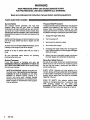
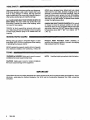
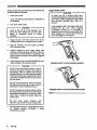
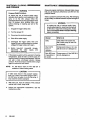
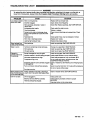
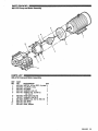
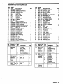
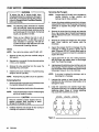
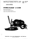
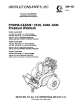
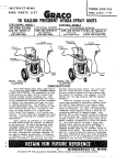
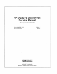
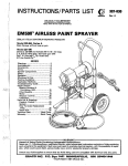
INSTRUCTIONS-PARTS LIST
This manual conteins IMPORTANT
WARNINGS and INSTRUCTIONS
READ AND RETAIN FOR REFERENCE
HYDRA-CLEAN 4040
Pressure Washer
@
Model 800-345, Series A 230/460 Volt, 3 Phase
4ooo psi (276 bar) OPERATING PRESSURE
4300psi (296 bar) MAXIMUM WORKING PRESSURE
GRACO INC. RO. Box 1441 MINNEAPOLIS, MN 55440-1441
@COPYRIGHT1990,GRACO INC.
~
BNG
HIGH PRESSURE SPRAY CAM CAUSE SERIOUS INJURY.
FOR PROFESSIONAL USE ONLY. OBSERWE ALL WARNINGS.
Read and understand all instruction manuals before operating equipment.
FLUID INJECTIONHAZARD
General Safety
This pressure washer
generates
very
high fluid
pressure.Sprayfromthegun,leaksorruptured
components can injectfluid through your skinand into
your body and cause extremely serious bodily injury
includingtheneedforamputation. Als0,fluid injectedor
splashed into the eyes
or on theskin can cause serious
damage.
Pressure Relief Procedure
To reduce the risk
of serious bodily Injury, includingfluid
injectionandsplashing in theeyesorontheskin,
always follow thisprocedure whenever you stop
spraying for more than
10 minutes, when shutting down,
and before checking
or repairingany part of the system.
NNER point the spray gun or wand
at anyone of at any
part of the body. NNER put hand or fingers over the
spray tip.
2. Turn the sprayer off.
ALWAYS follow the Pressure Rellef Procedure, before
cleaning or servicing any part of the sprayer.
1. Engage the trigger safety latch.
3. Disconnect the electrical supply.
4.
Shut off the water supply.
NNER try to stop or deflect leaks with your hand or
body.
5. Disengage the trigger safety latch and trigger the
gun to relieve pressure, and then engage the trigger
safety latch again.
Be sureequipmentsafetydevicesareoperating
properly before each use.
6. Beforelong-term(overnight)storage,disconnect
the water supply and disconnect the electricity.
Medical Treatment
If any fluid appears to penetrateyourskin,get
EMERGENCY MEDICALTREATMENTATONCE.
DO
NOTTREATAS A SIMPLE
CUT. Tell the
doctor exactly
what fluid was injected.
Spray Gun Safety Devices
Be sure all gun safety devices are operating properly
before eachuse. Do not remove ormodify any part of
thegun; this can cause a malfunction and result in
serious bodily injury.
NOTE TOPHYSICIAN: lnjection in the skin is a
traumatic injufg It Is Important to treat the Injury
surglcally as soon as posslble. Do not delay
treatment to research toxicip Toxicily is a
concern with some exoticcoatings injected
directw into the bloodstream. Consultation
with a
plastic surgeon or reconstructive hand surgeon
may be advisable.
S A F m LATCH: Whenever you stop sprayingfora
moment, always set the gun safety inlatch
the engaged
0r"safe" position, makingthe guninoperative. Failure
to
properly set the safety latch can result in accidental
triggering of the gun.
2
308-522
SPRAY TIP S A F m Use extreme caution when
cleaning or changing spray tips. If a spray tip clogs
while
spraying,
engage
the
gun
safety
latch
immediately. ALWAYS follow the Pressure Relief
Procedure and then remove the spray
tip to clean it.
..
.. ...
DANGER
This product must be grounded. If it should malfunction
or breakdown,groundingprovidesa
path of least
resistance for electriccunent to reducetherisk of
electric shock. This equipmentis equipped with a cord
having an equipment-groundingconductoranda
groundingplug. The plug must be plugged Into an
appropriate
outlet
that is properly installed and
grounded in accordancewith all local codes and
ordinances.
Improper
connection
of the
equipmentgrounding conductor can result in the risk of
electrocution. Check with aqualified electrician
orserviceperson if youare in doubtas to
whether the outletis properly grounded. Do not
modify the plug provided with the product- if it
will not fit theoutlet,haveaproperoutlet
installed by a qualified electrician.
GROUND FAULT CIRCUIT INTERRUPTER PROTECTION
receptacle that is protected by ground-fault
a
circuit-intempter (GFCI).
To comply with the National Electrical Code
(NFPA 70)
and to provide additional protection from the risk of
electric
pressure
washer
connect
shock,
this
to a
..
,
EXTENSION CORDS
Use only 4-wire extension cords that have 4-prong
grounding-type plugs and 4-pole cord connectors that
accept the plug from the product. Use only extension
cords that are intendedforoutdoor
use. These
extension
cords
are identified by marking,
a
"Acceptable for
use
with
outdoor
appliances;
store
indook while not in use." Use only.extension cords
having an electrical rating notless than the rating
of the
product.
Do
not
use
damaged
extension
cords.
Examine extension cord before using and replace if
cord and do not yank
damaged. Do not abuse extension
'
or pull on any cord to disconnect. Keep cord awayfrom
heat and sharp edges. Always disconnect the extension
cord fromthereceptaclebeforedisconnectingthe
Droduct from the extension cord.
WARNING 1-
1
To reducetheriskofelectrocution,
keep all
connectionsdry and off the ground.Donot
touch plug with wethands.
EQUIPMENT MISUSEHAZARD
General Safety
System Pressure
Any misuse of the pressure washer or accessories,
such
as
overpressurizing,
modifying parts,
using
incompatible chemicals and fluids, or using worn or
damaged parts, can cause
them to rupture andresult in
fluid injection, splashing in the eyesor on the skin, or
other serious bodily injury, fire, -explosion or property
damage.
This sprayer can develophigh operating pressure. Be
sure thatall spray equipment and accessories rated
are
to withstand the maximum workingpressure of this
sprayer. DO NOT exceedthemaximumworking
pressure of any component or accessory used in the
system.
N N E R alter or modify any part ofthis equipment; doing
so could cause it to malfunction.
BE SURE that all chemicalsused in thechemical
injector are compatible with the wetted parts of the
hose, gun, wand andtip, as given in the Technical Data
(inside back cover). Always read the chemical
manufacturer's literature before using any chemicalin
this pressure washer.
CHECK all spray equipment regularly and repair or
replace worn or damaged park immediately.
Chemical Compatibility
"
ALWAYS wear protective eyewear and appropriate
clothing. If using a chemical injector, read and follow
chemical
the
manufacturer's
literature
for
recommendations on additional protective equipment,
such as a respirator.
308-522
3
HOSE SAFETY
Highpressurefluid in the hoses canbe very dangerous.
Ifthe hose develops aleak, split or rupture dueto any
kind of wear, damage or misuse, the high pressure
spray emittedfrom it can causefluid
a injection injury or
other seriousbodily injury or property damage.
ALL FLUID HOSES MUST HAVE STRAIN RELIEFSON
BOTH ENDS. The strain reliefs help protect the hose
from kinks or bends at or close to the coupling, which
can result in hose rupture.
TlGHTEN all fluid connections securely before each
'use. High pressure fluid can dislodge a loose coupling
or allow high pressure spray to be emitted from the
coupling.
NNER use a damaged hose. Beforeeach use, check
entire hose forcuts, leaks, abrasion,bulging cover, or
damage or movement of the hose couplings. If any of
these condRions exist, replace the hose immediately.
DO NOT try to recouple high pressure hose or mend it
with tape or any other device.A repaired hose cannot
contain thehigh pressure fluid.
HANDLEAND ROUTEHOSES CAREFULLY Do not pull
on hoses to move the pressure washer. Do not use
chemicals which are not compatible wlth inner
the tube
and cover of the hose.
DO NOT expose Gracohose to
temperatwes above 2M)" F (93' G)M below 4
0
'F
(-400
C).
MOVING PARTS HAZARD
Moving partscan pinch oramputatefingersorother
body parts. KEEP CLEAR ofmoving parts when starting
or operating the pressure
washer.
Pressure
Rellet
Procedure
before checking or
servicing the pressure washer to prevent discharging
high pressure fluid from the gun.
NNER operate the pressure
washer withoutall guards
and interlocks installed andfunctioning.Followthe
TERMS
WARNING or DANGER Alertsuser to avoid or correct
conditions that could cause bodily injury.
NOTE
Identifies helpful procedures and information.
CAUTION Alerts user to avoid or correct conditions
that could cause damageto the equipment.
IMPORTANT
United States Government safety standards have been
adopted under the Occupational Safety
and Health Act. These
standards-particularly the General Standards, Part 1910, and the Construction Standards, Part 1926-should be
consulted.
4
308-522
INSTALLATION
PUMP
DIPSTICK
MOTOR
PUMP OIL LEVEL
INDICATOR
CONNECTION 314"
GARDEN HOSE (9
Figure 1
Check for Shipping Damage
Check the unit for
any damage that mayhave occurred
in shipping. Not@ the carrier Immediately if there is
any damage.
Set Up
Beforeplugging in the unit,
be sure theelectrical service
matchesthespecification
in TechnicalData (inside
back cover) and the voltagelabel on the unit. With the. ,
unit off, plug the power supply cord into a grounded,
GFCi-protected outlet. Donotremovethe
electrical
plug which comes with the unit or bend connecting
prongs tofit an improper outlet! Use an extension
cord
that meets the requirementsof the EXTENS/ON CORD
section andis no more than100 fl(30 m) long. Added
length of cord will affect current draw of unit.
If you are using a downstream chemical injector,
install it
betweenthepumpunloader and the high pressure
hose, using the quick couplers provided.
Connect the high pressure hose between the pump
outlet and the gun inlet. Both of these connections
are
made with quick couplers.
1-
CAUTION
Up lo 100 ft (30m) of high pressure hose may
beused. Longerhosesmayaffectsprayer
and
chemical
injector
performance, if used.
Installtheappropriatespray
tip on thewand.See
lnstaliing and ChangingSpray Tips. If you are using a
sandblaster kit, seeits separate manual forinstallation
instructions.
Connect to Water Supply
CAUTION
Before attaching
to the water supply, check your
local plumbing code regarding crossconnection to the water supply.
A backilow preventer, P/N 8 0 1 -1 33, is available
to prevent backflow of contaminated water Into
the fresh water supply. Install it upstream from
the pump.
Install a regulating
water valve, P/N 800-258, if
inlet water pressureis over €0psi (4.1 bar).
Do notexceed 160° F (70" C) inlet water
temperature.
Connect ahose with at least a3/4 inch (19 mm) IDand
not longer than
50 fl(15 m) to the unit's 314 Inch garden
hose inlet.
NOTE
m e watersourceatthe
unit must havea
minimum flowrate equalto that of the unit (see
Technical Data, inside back cover).
308-522
5
STARTUP
Always use this start up procedureto ensure that the unit Trigger Safety Latch
is started safely and properly.
WARNING
1. Check the oil level.
Pump: Add SAE X
I or 30 weight non-detergent oil
as necessary.
To reduce the risk of serious bodily injury,
including fluid injection, splashingin the eyesor
on the skin,ALWAYS engage the trigger safety
latch whenever spraying stops, evenfora
moment.
2. Tum on the water supply.
CAUTION
In the engaged position, the trigger safety
latch
prevents
the
gun
from
being triggered
accidentally by hand or ifit is dropped or
bumped. Be sure thelatch is pushed fully down
when engaging it or it cannot prevent the gun
from being triggered. See Figure 2.
I
Never run the unit dry. Costly damage to the
pump will result.Always be sure the water
supply is completely
tumed
on before
operating.
3. Triggerthegun
until waterspraysfromthe
tip
indicating that the air is purged from the system.
4.
Plugtheelectrical
cord into proper,grounded,
GFCI-protected outlet.
5. ALWAYS engagethegun’striggersafety
latch
whenever you stop spraying, even for a momentto
reduce the riskof fluid injection or splashing in the
eyes or on the skin
if the gunis bumped or triggered
accidentally.
6. ALWAYS observe the following CAUTIONS to
avoid
costly damage to the pressure washer.
TRIGGER SAFETY LATCH SHOWN ENGAGED
CAUTION
DO NOT allow the pressure washerto idle for
more than10 minutes. Doingso may causethe
recircuiating water lo overheat and seriously
damage the pump.
Tum off the pressure washer
if it will not De sprayingor cleaningat leastevery
10 minutes. If heated inlet water
is used, reduce
this timefurther.
DO NOT run the pump dry, which will quickly
damage the pump.
Be sure the watersupply is
fully tumed on before starting the pump.
DO NOT operate the pressure washer with the
inlet water screen removed. This screen helps
keep abrasive sediment out of the pump, which
could clog or scratchthepump,Keepthis
screen clean.
DO NOT pump caustic materiais;
such
materials may corrodethe pump components.
7. See the chemical injectoror sandblasterkit manual
for detailed cleaning
information
these
if
accessories are used.
6
308-522
TRIGGER SAFETY LATCH SHOWN DISENGAGED
Figure 2
Installing and Changing Spray lips
WARNING
To reduce therisk of serious bodily injury,
including fluid injection or splashing inthe eyes
orontotheskin,useextremecautionwhen
changing
spray
tips.
ALWAYS follow the
procedure below.
CAUTION
To avoid blowing the O-ring out of the qulck
coupler, dueto the high pressure
in the system,
never operatethe pressure washer without
a tip
securely mounted in the quick coupler.
1. Follow the Pressure Rellet Procedure.
2. Pointthegunandwandaway
anyone else.
from yourselfand
3. Without holding your hand over the spray tip (A),
pull back the quick coupler ring(B), remove the tip
and then release the ring.See Figure 3.
4. Be surethe tip is secure before starting to spray
again.
5. Tip holding holes are provided on the chassis.
Figure 3
308-522
7
SHUTDOWN, FLUSHING
AND STORAGE
MAINTENANCE
Observing regular maintenance intervals
helps ensure
that you get maximum performance and life from the
pressure washer.
WARNING
Pressure Rellef Procedure
To reducetherisk
of serious bodily injury,
including fluid injection and splashing in the
eyes,
or
ontheskin,always
follow this
procedurewhenever you stop spraying
for more
than 10 minutes,whenshuttingdown,and
before checking or repairing any part ofthe
system.
1. Engage the trigger safety latch.
2. Tum the sprayer off.
There is a break-inperiod for the pump. Afler changing
the oil initially, the interval between required changes
Is
longer.
WARNINGI To reducetherisk
of serious bodily injury,
includingfluid injection, splashinginthe eyes or
on the skin or injury frommoving parts, always
follow the Pressure Relief Procedure
Warning
3. Disconnect the electrical supply.
4. Shut off the water supply.
5. Disengage thetriggersafetylatch
and
trigger the gun to relieve pressure, and then
engage the trigger safety latch
again.
6.
Before
long-term
(overnight)
storage,
disconnect the water supply
and
disconnect the electricity.
1. If the pressure washer will be exposed to freezing
temperatures, drain all water out of the pump. If it
must be stored in freezing temperatures, flush the
unitwitha
50% anti-freezesolution.Relieve
pressure. Flush the pressure washer before
using it
again to remove the anti-freeze.
NOTE:
An anti-freeze
flush
kit P/N 802-327 is
available to make flushingeasier.
CAUTION
Ifwater does freeze in thepressurewasher,
thaw it in a warm room before trying tostart it.
DO NOT pour hot water on or into the pump; it
2. After each use, wipe all surfaces of the pressure
washer with a clean, damp cloth.
3. Perform the appropriatemaintenance.
maintenance chart.
E
308-522
See the
interval
What to do
Daily
Clean
water
inlet screen and
filter. Check pump oil level. Fill
as necessary.
After first 50
hours of
operation
Changepumpbreak-in oil. Use
SAE 20 or 30 non-detergent oil.
Each 500 hours Change pump oil. Use SAE 20 or
of operationor 30 non-detergent oil.
6 months
I
TROUBLESHOOTING CHART
WARNING
To reduce the risk of seriousbodily injury, including fluid injection, splashing in the eyes or on the skin, or
injury from moving parts, always fallow the Pressure Relief Procedure Warning before proceeding.
CAUSE
I
SOWTION
PROBLEM
tip.
Replace withtip of proper size.
DW pressure and/or Wom or wrong size
ump runs rough Inlet filter clogged.
Clean. Check more frequently.
Checlc filter. Replace packings.See PUMP SERVICE.
Wom packings, abrasivesin water or
natural wear.
Check water flowrate to pump.
Inadequate water supply.
Tighten or replace.
Coupling slippage.
Fouledor dirty inlet or discharge valves. Clean Inlet and discharge valve assemblies. Check
filter.
Even a small particle can cause the valve
lo stick.
Reslricted inlet.
Check garden hose. maybe collapsed orkinked.
Replaceworn valves.
Worn inlet or discharge valves.
Reolace hlahm w r e hose.
Leakina hiahm s u r e hose.
rater leakage from Wom packings.
Install new packings.See PUMP SERVICE.
nder pump manifolc
rater in pump
Humid air condensing inside crankcase. Change oil as specifiedin MAINTENANCE.
Install new packings.See PUMP SERVICE.
Wom packings.
Install newoil seals. See PUMP SERVICE. Oil seals leaking.
e
'q
e
q
u
e
n
t or
See PUMP SERVICE.
Scored, damaged or worn plungers. Install new plungers.
emature failure of Abrasive material in the fluid being pumped.
Install proper filtration on pump inlet plumbing.
1
8 packings
Inlet water temperaturetoo high.
Check water temperature; maynot exceed 160°F.
Overpressurizing pump.
Do not modify any factory-set adjustments.
See
EQUIPMENT MISUSEHAZARD.
Excessivepressuredue to partiallypluggedorreplace
tip. See InstallingandChangingSpra)
or damaged tip.
10 minutes without spraying
Pump runningtoo long without spraying. Never run pump more than
Do notrun pump without water.
Running pump dry.
lrong surging at theForeign particlesin the inlet or discharge Clean or replace valves.See PUMP SERVICE.
let and low pressurt valve or wom inlet and/or discharge valves.
1 the discharoe side
nit will n d start
Unit not pluggedin.
Check power cord.
Electrical service off/GFCI activated.
Check fuse/circuit breaker. Check for proper
grounding.
mermai overload has tripped.
Press stop button on
the motor starter.
308-522
9
PARTS DRAWING
800-345 Hvdra-Clean@4040 Pressure Washer
For wiring diagram, see page14
~~~~~
10
308-522
PARTS LIST
800-345 Hydra-Clean@4040 Pressure Washer
REF PART
NO.
DESCRIPTION
NO.
DESCRIPTION
QN
NIPPLE,
Hex
800-579 PUMP & MOTORASSEMBLY
35 3/8 156-849
803-591WASHER, Flat 1/2
1
36
(see page 15)
802-784
WASHER,
Lock 112
803-554BRACKET,PumpSupport
1
37
2
803-592SCREW,Cap,hexhd.
801-382CORD,Power10/4
38
48 in
3
1/2-13
4 X 1-1/2
1
4
803-263BRACKET.Starter. left
801-012GROMMET.,Rubber
39
159-239 NIPPLE, Hex 1/2 x 3/8
2
5
800-124TIPASSEMBLY, OOO4
802-732WASHER.Flat #6
4
40
6
(includes 4 5 , 60)
802-731
WASHER:
Lock #6
4
7
800-125TIPASSEMBLY,1504
41
803-484
SCREW,
Cap,
pan4hd.
8
(includes 45, 61) 1
803-517
LABEL,
Keep
From
Freezing
1
9
800-126TIPASSEMBLY,2504
42
1
800-427UNLOADER, 4ooo psi
10
(includes
1 45, 62)
11
800-450HOSEASSEMBLY, w/Quick
800-127TIPASSEMBLY. 4004
Couplers (includes 14, 18, 20) 1
43
(includes 45,’63)~
12
801-009QUICKCOUPLER, Femaie 1/4
801-WBDECAL.GracoG
1
44
Soi-Os0 QUICKCOUPLER, Male 1/4
154-594 O-RING, (includes Quic
1/4 13L1 Coupler
45
13
176-250LABEL,Warning, chassis
14
801-568
QUICK
COUPLER,
Male
3/8
46
2
47
176-981LABEL,Warning.
chassis
802-534 NIPPLE, Hex 1/2 NPSM X
15
803-396
LABEL,
WamingICavtion
1
1
48
112 NPT
49
803-141HOSE,Bvoass
1
100-527 WASHER, Flat 5/16
16
100-21 4 WASHER, Lock 5/16
803-395
LABEL,
Model1 4040
50
17
803-519 HOSE, High Pressure 3/8 x 50 ft 1
100-188 NUT, Hex 5/16-18
51
18
803-007 LABEL, Caution, 230 volt,
800-429GUN &WAND ASSEMBLY
19
52
3 phase
fincl.12.20.28.29.34.35)1
803-006 LABEL, Caution, 460 volt,
803-157 QUiCK COUPLER, Femaie 318
20
152
phase
3
2 (includes 21)
CONNECTOR,
801-226
4 Wire
156-082 O k N G , Quicik
Coupler
3/8
2
53
21
801-382CORD.Power12/4
402-278PLUG. Plastic
1
54
22
802-81 1 CORD’GRiP
STRAiNEWFiLTER
55
231 804-051
804-043SWITCH.Starter.15
hD 230 Volt
801-110ADAPTER, Garden Hose
1
56
24
803-749SWITCH:Starter:15
hp 460 Volt
801-111NUT,Garden Hose
1
25
57
27 112801-106 TEE.
801-937 NUT. Lock. electrical
1
801-523 NIPPLE, 1i2 X 2
801-957 SLERIE, 18”
1
58
28
WAND,
34 29 -1 801
32
1
801-221 TERMINAL. Rina
59
803-262
BRACKET,
Starter,
1right
30
801 -599 TIP, Spray 6
60
0
0
4
’
CHASSiS31
800-441
80-600 TIP SDrav 1504
61
802-993PLUG,-Locking15hp,460volt1
801-661 TIP; sprai, 2504
32
62
801-602 TIP SDrav 4004
803-186LABEL,Cordset
33
63
1
803-351GUN,Spray,SST
34
(See
801-304 TERMINAL, Ring
64
InstructionManual308-51 1)1
REF
NO.
1
PART
NO.
ON
1
4
4
5
1
~~~
1
2
~
4
1
1
2
2
2
1
8n
3
1
1
1
308-522 11
I
12
308-522
53
Model 4040
Wirlng Diagram
230 Volt. 3 Phase
Model 4040
Wring Diagram
460 Volt, 3 Phase
PARTS DRAWING
800-579 Pump and Motor Assembly
PARTS LIST
800-579 Pump and Motor Assembly
REF
NO.
1
2
3
4
5
6
7
8
9
10
11
PART
NO.
803-584
hp
802-698
802-540
802-784
803-750
DESCRIPTION
QTY
MOTOR, 15.0 hp TEFC, 3 phase 1
COUPLER,
15
1
HOUSING
1
WASHER, Lock 1/2
4
SCREW, Cap, socket hd.
1/2-13 X 3
4
802-508 PUMP (see page 16)
1
100-527 WASHER,
4
Lock
5/16
801 -559 SCREW, Cap, hex hd. M8 x 30 4
802-783 K M , Motor
1
802-794 KM,Pump
1
803-552 RING, Adapter
1
308-522 13
PARTS DRAWING
803-508 Pump Assembly,4000 psi
1
45
-//
/-
14
308-522
PARTS LIST
803-508 Pump Assembly, 4000 psi
REF
.PART
.....
REF
PART
NO. NO.
1
2
3
4
5
6
7
8
9
10
11
12
13
14
15
16
17
18
19
20
21
22
23
24
25
26
27
DESCRIPTION
801-647MANIFOLD ~801-468SCRNV,Cap,hexhd.
801-469WASHER.
Lock
KIT 1
O-RING
SEAT, Valve
KIT 1
KIT 1
PLATE, Valve
KIT 1
SPRING
KIT 1
GUIDE, Valve
KIT 106 O-RING
KIT 106 CAP
KIT 1
VALVE ASSEMBLY
803-283 SCREW, Cap, sockethd.
803-506 COVER, Crankcase
802-500 O-RING, Crankcase Cover
803-324 BEARING, Tapered Roller
KIT 2
SEAL, Oil
803-286 BUSHING, Piston
803-501 CRANKCASE
801 -475 DIPSTICK
803-1 44 GASKET, Cover
803-287 CRANKSHAFT
803-288 RING, Retaining
802-794 KEY
803-289 PIN, Wrist
803-503 GUIDE, Piston
803-291 ROD, Connecting
803-292 SCREW, Cap, socket hd.
~~
~
~~
Repalr Kit
Part No.
Ret.
1
801-472
Valve
4
No.
5
6
7
8
11
2
3
106
801-473
16
Oil Seal Kit
802-511
41
Crankshaft
Seal
802-509
Valve
Cap
4000 psi
1
8
8
~~~
Klt
No.
9
10
NO. NO.
QTY
8
1
2
2
1
1
1
1
1
6
1
3
3
3
DESCRIPTION
803-507COVER,
Crankcase
802-345GAUGE,
SigM
802-793PLUG,
Oil Drain
KIT
107
O-RING
803-294 SCREW, Cap, socket hd.
801-652WASHER,
Lock
KIT107WASHER,
Flinger
801-490PLUNGER,
Ceramic
803-502PLUNGER,Ceramic
KIT107RING,
Backup
KIT
107
WASHER
KIT
107
SCREW,
Piston
803-505COVER,Crankcase
803-296
SHIM
KIT 3
SEAL, Oil
KIT 109 O-RING
KIT 109 RETAINER. Packing
KIT 109 PACKING
KIT 112 PACKING
KIT 109 RING, Head
KIT 109 RETAINER, Packing
KIT 109 RING, Long Life
801-482 PLUG, Hex
801-483 WASHER, Flat
801 -484 PLUG, Hex
801 -485 WASHER, Flat
28
29
30
31
32
33
34
35
36
37
38
39
40
41
42
43
44
45
46
47
51
52
53
54
6
6
6
6
6
6
SEAL. Oil
3
Kk
No.
QW
Repalr Kit
Part No.
3
3
1
2
1
1
1
1
Ref.
No. Descrlptlon
WASHER,
Plunger
RING,Repair
2
I
6
6
t
I46
I I
112
QiY.
Flinger
Backup
Retainer
O-RING
CAP
6
6
5
Descrlption
O-RING
SEAT, Valve
PLATE, Valve
SPRING
GUIDE,
Valve
.
VALVEASSEMBLE
SEAL, Oil
QTY
1
1
1
Packing
PACKING
RING. Head
I RETAINER,
I1
.
803-512
Packing
4ooo psi
44
PACKING
6
308-522 15
PUMP SERVICE
Servicing the Plungers
I
1
I
To reducetherisk
Of serious bodily injury,
includingfluid injection, splashingin the eyes or
on the skin, or injury from moving parts, always
follow the Pressure
Relief ProcedureWarning
WARN'NG
before
proceeding.
I
NOTE: The following metricwrenchesareneeded:
M10,M13 a n i M30.
ReDair kits are available.
Refer to the individual repair sections
and the
pump parts
page for moredetails. For the best
results, useall parts in the kits.
NOTE
Thereare two different tool kits to aidin
servicing the pump. P/N 800-298 is used to
ease installation of packings. P/N 800-271
includes the items in800-298 andtools to aid
in the removalof packing retainers.
NOTE
1. Loosentheplungerretainingscrew five to sixtums,
using an M10 wrench. Push the
plunger towards the
and retaining
crankcase to separate the plunger
.
.
screw.
2. Remove the screw from the plunger
and examine
the O-ring,backup ring and copper bearindgasket
washer. Replacethese parts,ifnecessary,using kit
803-510.
3.Removethe
plunger and flinger from the plunger
shaft.
Clean,
examine
and
replace parts
as
necessary.
4.
Valves
NOTE
For a set of six valves, order P/N 801 -472.
1. Remove the hex plug
.
- from the manifold using an
M30 wrench.
plug and replace
2. Examine the O-ring under the hex
it if itis cut or distorted.
3. Remove the valve assembly from the cavity; the
assembly maycome apart.
the O-ring and hex
plug;
4. lnslall the newvalve. Install
torque to 75 ft-lb (103 Nm).
NOTE
Plunger repair kit, P/N 803-510 is available to
replace retainers,
O-rings,
washers
and
backup rings for three cylinders.
Inspect the plunger shaft for oil leakage from the
crankcase. If leaking is obvious, replace the oil
seals. Otherwise, DO NOT remove these seals as
they cannotbe reused. An oil seal kit is availableto
replace the seals.
5. Lightly grease the oil seal, if it is being replaced,
and the flinger and replace them on the plunger
shaft. Theninstall the plunger.
6. Lightly grease the retaining screw
and the outer end
of the plunger. Place the washer, O-ring
and backup
ring around the screwand install the screw through
the plunger. Torqueto 14.4 ft-lb (19.5 Nm).
NOTE:
Retorque the plug after 5 hours of operation.
If vou plan to replace the Packinas.
- refer to
Sitvicing the V-backings. '
7. Lubricatetheoutside of each plunger. Slide the
manifold onto the crankcase, being careful not to
1. Remove the eight capscrews and lockwashers from
damage the seals.
the manifold using an M13 wrench.
8. Installthecapscrews
and washersfinger-tight.
2. Carefully separatethemanifoldfrom the crankcase.
Torque the screws
to 21.7 ft-lb ( 2 9 Nm) following the
tighteningpattem (Figure4).Uneven
tightening
NOTE: It may be necessaryto tap themanifold lightly
may cause the manifold
to bind or jam.
with a soft mallei to loosen.
Pumping Section
I
Keep the manifold properly aligned with the
ceramicplungers whenremoving to avoid
damage to the plungeror seals.
3. Carefully examine each plunger for any scoring or
cracking and replace as necessary.
Figure 4
16
308-522
I
Servicing
V-Packings
the
NOTE There are two lypes of packing kits: one is
5. Thoroughly clean
the
packingcavities and examine
for debris and damage.
pacltlngs
only,
the
other
includes the
packings, ringsand retainers.
6. Lightlygreasethe
packing cavitiesandthen
replace the packings in the following order: head
ring,
v-packing.
intermediate
ring,
head ring,
v-packing and packing retainer with. theO-ring
installed In the retainer groove.
1. Remove the manifold as outlined In the Pumping
Section.
2. Carelully pull the packing retainer
from
the
manifold. Examine the O-ring andreplace It if it is
cut or damaged.
the
3. Remove the v-packing and head ring. Pull out
intermediateretainerring.Removethe
v-packing and second head ring.
second
CAUTION
Install the parts in the proper order andfacing
the correct direction. Improperly installed parts
will cause a malfunction.
7. Reassemble ¶hemanifold as instructed in Servicing
the Plungers.
4. inspect all parts and replace as necessary.
308-522 17
~
ACCESSORIES
(Must be purchased separately)
DOWNSTREAM
CHEMICAL
INJECTOR
KIT
WATER
SANDBLASTING
KIT
800-120
For
cleaning
abrasive
800-649
For injecting harshcleaningchemicalsdownstream
from the pump. Stainless steel construction.
UPSTREAM CHEMICAL INJECTORKIT
800-257
For injecting mild cleaning chemicals upstream
into the
Pump.
dirt
of stubborn
and paint.
Requires a spray
tip (801-600) which is not included in
kit.
ANTI-FREEZE FLUSH KIT 802-327
For flushing system with
50% anti-freeze solution prior
to transporting or storing pressure washer in below
freezing temperatures.
BACKFLOW
PREVENTOR
801-133
INLET
PRESSURE
REGULATOR
800-258
Prevent back-up of contaminated
water
into
fresh
Regulates
inlet
water
pressure
supply. Install upstreammaximum.
of pump.
to 60 psi (4 bar)
TECHNiCAL DATA
High Pressure Hase
Acrylonitrile and Buna-Ncoverandtube
Synthetic yam andEPDM
PressureWasherAnodizedaluminum,AluminumorBronzealloys,
Brass, Copper,Nylon-TefionQcomposite.
(including fittings)
Ceramic, Buna-N, Conon Phenolic. 303,304, and 316 Stainless Steel. Polymide-12
Thermoplastic. Teflono, CarbonSteel, Zinc with or without Yellow Chromare Plate
THE GRACO WARRANTY
WARRANTY AND DISCLAIMERS
Gram warrants ail equipment manufachrred
by fi and bearing its name
to be frea from defectsin material
andwo~manshiponthedateofsaiebyanauthorizedGramdistnbutortotheonginalpurchaserforuse.
As purchaser's sole remedy for breach
ofthis warranty, Graco will,
for a period
of twenty four months
from
dateofsale,repairorreplaceanypartoftheequipmentpmvendefscthe.Thiswarran~appliesonlywhen
the equipment is installed.
operated
and maintained in accordancB
with
Gram's written
recommendations.
or caused
This warranty does not cover. Gram
and shall not be liable for, any malfunction. damagewear
by tauily installation.misapplication.abrasion,corrosion,inadequateorImpropermaintenance,
negligence. accident, tampering, or substihltion of non-Graco component parts Nor shall Graco be
liableform~nction,damageorwearcausedbytheinmmpatibilitywithGramequipmentofsfruchrres,
accessories. equipment or materials not supplied by Graco. or the improper design, manufacture,
installation. operation or maintenance
of sfruotures. accessories.equipmentor materials not supplied by
Grm.
Thii warranty is conditioned upon the prepaid return of the equipment claimed to be defective for
examination by Gram to verify the claimed defect.If me claimed defect is
verified. Graco will repair or
replace free of charge any defecthe parts. The equipment will be returnedto the original purchaser
transportation prepaid. If inspection of the equipment does not disclose any defect in material or
be madeata reasonable charge. which charges may
include thecosts
of parts.
workmanship. repairs will
labor and transportation.
DISCLAIMERS AND LIMITATIONS
METERMSOFTHlSWARRANPlCONSTiTUTETHEPURCHASER'SSOLEANDEXCLUSlVEREMEDY
ANDAREINLlEUOFANYOTHERWARRANTIES(EXPRESSORIMPLIED),lNCLUDlNGWARRANTYOF
MERCHANTABILITY OR WARRANTY OF FITNESSFOR A PARTICULARPURPOSE,AND OF ANY
NON-CONTRACTUALLIABILITIES. INCLUDING PRODUCTLIABILITIES. BASEDON NEGLIGENCEOR
STRICTLIABILITY: EVERY FORMOF UABiLlTY FOR DIRECTSPECIAL OR CONSEQUENTIAL
IN NOCASESHALLGRACOS
DAMAGES OR LOSS IS EXPRESSLYEXCLUDEDANDDENIED.
LIABILITYEXCEEDTHEAMOUNTOFTHEPURCHASEPRICE.
ANY ACTIONFORBREACH OF
WARRANTY MUST BE BROUGHT WITHIN THREE (3) YEARS OF THE DATE OF SALE.
EQUIPMENT NOT COVEREDBY GRACO WARRANTY
GRACOMAKESN0WARRANPl.ANDDiSCLAlMSALLIMPLIEDWARRANTIESDFMERCHANTABlLlTY
ANDFITNESSFOR A PARTICULARPURPOSE,WITHRESPECTTOACCESSORIES,EQUIPMENT
MATERIALS OR COMPONENTS SOLD BUT NOT MANUFACTURED BY GRACO. Theseitems sold, but
notmanufacturedbyGraw(suchaselectricmotor,switches,hose,etc.)aresubjecttothewarranty,ifany.
of their manufacturer. Graco willprovide purchaser with reasonable assistance in making any for
claim
breach of these warranties.
IMPORTANT PHONE NUMBERS
TO PLACE AN ORDER, wntacd your Graw distributor, or call this number to identify the
distributor closest to you: 1-800-328-021 1 Toll Free
FOR TECHNICAL ASSISTANCE, service repair information or assistance regarding the
application of Graw equipment: 1-800-543-0339 Toll Free
Factory Branches:Atlanta, Chicago. Dallas, Delmi. Los Angeles. West Caldwel (N.J.)
Subsldlary and AffiliateCompanies: Canada; England; Swiizeriand; France; Germany; Hong Kong:Japan: Korea
GRACO INC. PO.BOX 1441 MINNEAPOLIS, MN 55440-1441
PRINTED IN U.S.A. 308-522 1/91