1
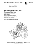
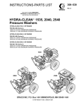
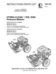
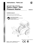
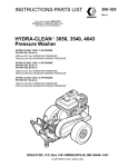
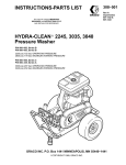
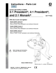
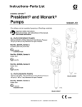
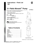
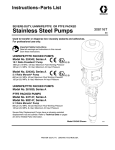
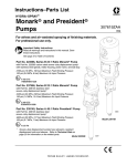
INSTRUCTIONS-PARTS LIST
308–507
Rev B
Supersedes A
This manual contains IMPORTANT
WARNINGS and INSTRUCTIONS READ
AND RETAIN FOR REFERENCE
HYDRA-CLEAN MONARK, PRESIDENT
Pressure Washer
HYDRA-CLEAN 5:1 MONARK – CART MOUNTED
P/N 800–412, Series A
900 psi (62 bar) MAXIMUM WORKING PRESSURE
2.5 gpm (10 lpm) MAXIMUM FLOW RATE
HYDRA-CLEAN 10:1 PRESIDENT – CART MOUNTED
P/N 800–413, Series A
1800 psi (124 bar) MAXIMUM WORKING PRESSURE
3.0 gpm (11 lpm) MAXIMUM FLOW RATE
HYDRA-CLEAN 10:1 PRESIDENT – PORTABLE TANK MOUNTED
P/N 800–295, Series A
1800 psi (124 bar) MAXIMUM WORKING PRESSURE
3.0 gpm (11 lpm) MAXIMUM FLOW RATE
GRACO INC. P.O. Box 1441 MINNEAPOLIS, MN 55440–1441
COPYRIGHT 1990, GRACO INC.
WARNING
HIGH PRESSURE SPRAY CAN CAUSE SERIOUS INJURY.
FOR PROFESSIONAL USE ONLY. OBSERVE ALL WARNINGS.
Read and understand all instruction manuals before operating equipment.
FLUID INJECTION HAZARD
General Safety
This pressure washer generates very high fluid pressure.
Spray from the gun, leaks or ruptured components can
inject fluid through your skin and into your body and
cause extremely serious bodily injury including the need
for amputation. Also, fluid injected or splashed into the
eyes or on the skin can cause serious damage.
NEVER point the spray gun or wand at anyone or at any
part of the body . NEVER put hand or fingers over the
spray tip.
Pressure Relief Procedure
To reduce the risk of serious bodily injury, including fluid
injection and splashing in the eyes, or on the skin, always
follow this procedure whenever you stop spraying for
more than 10 minutes, when shutting down, and before
checking or repairing any part of the system.
1. Engage the trigger safety latch.
2. Turn the air supply off.
3. Disconnect the air supply.
4. Shut off the water supply.
ALWAYS follow the Pressure Relief Procedure, before
cleaning or servicing any part of the sprayer.
NEVER try to stop or deflect leaks with your hand or body.
Be sure equipment safety devices are operating properly
before each use.
Medical Treatment
If any fluid appears to penetrate your skin, get
EMERGENCY MEDICAL TREATMENT AT ONCE. DO
NOT TREAT AS A SIMPLE CUT. Tell the doctor exactly
what fluid was injected.
NOTE T O PHYSICIAN: Injection in the skin is a
traumatic injury. It is important to treat the injury
surgically as soon as possible. Do not delay
treatment to research toxicity. Toxicity is a concern
with some exotic coatings injected directly into the
bloodstream. Consultation with a plastic surgeon or
reconstructive hand surgeon may be advisable.
308–507
5. Disengage the trigger safety latch and trigger the gun
to relieve pressure, and then engage the trigger
safety latch again.
6. Before long–term (overnight) storage or transporting
of the unit, disconnect the water supply and
disconnect the air supply.
Spray Gun Safety Devices
Be sure all gun safety devices are operating properly
before each use. Do not remove or modify any part of the
gun; this can cause a malfunction and result in serious
bodily injury.
SAFETY LA TCH: Whenever you stop spraying for a
moment, always set the gun safety latch in the engaged
or “safe” position, making the gun inoperative. Failure to
properly set the safety latch can result in accidental
triggering of the gun.
SPRAY TIP SAFETY : Use extreme caution
when
cleaning or changing spray tips. If a spray tip clogs while
spraying, engage the gun safety latch immediately
.
ALWAYS follow the Pressure Relief Procedure and
then remove the spray tip to clean it.
EQUIPMENT MISUSE HAZARD
General Safety
Any misuse of the pressure washer or accessories, such
as overpressurizing, modifying parts, using incompatible
chemicals and fluids, or using worn or damaged parts,
can cause them to rupture and result in fluid injection,
splashing in the eyes or on the skin, or other serious
bodily injury, fire, explosion or property damage.
NEVER alter or modify any part of this equipment; doing
so could cause it to malfunction.
CHECK all spray equipment regularly and repair or
replace worn or damaged parts immediately.
ALWAYS wear protective eyewear and appropriate
clothing. If using a chemical injector, read and follow the
chemical manufacturer’s literature for recommendations
on additional protective equipment, such as a respirator.
System Pressure
This sprayer can develop high operating pressures. Be
sure that all spray equipment and accessories are rated
to withstand the maximum working pressure of
this
sprayer. DO NOT exceed the maximum working
pressure of any component or accessory used in the
system.
Chemical Compatibility
BE SURE that all chemicals used in the chemical injector
are compatible with the wetted parts of the hose, gun,
wand and tip, as given in the Technical Data (inside back
cover). Always read the chemical manufacturer
’s
literature before using any chemical in this pressure
washer.
HOSE SAFETY
High pressure fluid in the hoses can be very dangerous. If
the hose develops a leak, split or rupture due to any kind
of wear , damage or misuse, the high pressure
spray
emitted from it can cause a fluid injection injury or other
serious bodily injury or property damage.
ALL FLUID HOSES MUST HA VE STRAIN RELIEFS
ON BOTH ENDS. The strain reliefs help protect the hose
from kinks or bends at or close to the coupling, which can
result in hose rupture.
TIGHTEN all fluid connections securely before each use.
High pressure fluid can dislodge a loose coupling or allow
high pressure spray to be emitted from the coupling.
NEVER use a damaged hose. Before each use, check
entire hose for cuts, leaks, abrasion, bulging cover , or
damage or movement of the hose couplings. If any of
these conditions exist, replace the hose immediately. DO
NOT try to recouple high pressure hose or mend it with
tape or any other device. A repaired hose cannot contain
the high pressure fluid.
HANDLE AND ROUTE HOSES CAREFULL Y. Do not
pull on hoses to move the pressure washer. Do not use
chemicals which are not compatible with the inner tube
and cover of the hose. DO NOT expose Graco hose to
temperatures above 200 F (93 C) or below –40F
(–40 C).
MOVING PARTS HAZARD
Moving parts can pinch or amputate fingers or other body
parts. KEEP CLEAR of moving parts when starting or
operating the pressure washer.
NEVER operate the pressure washer without all guards
and interlocks installed and functioning. Follow the
Pressure Relief Procedure
before checking or
servicing the pressure washer to prevent discharging
high pressure fluid from the gun.
TERMS
WARNING: Alerts user to avoid or correct conditions
that could cause bodily injury.
NOTE:
CAUTION: Alerts user to avoid or correct conditions that
could cause damage to or destruction of equipment.
Identifies helpful procedures and information.
IMPORTANT
United States Government safety standards have been adopted under the Occupational Safety and Health Act. These
standards—particularly the General Standards, Part 1910, and the Construction Standards, Part 1926—should be
consulted.
308–507
3
INSTALLATION
AIR
MOTOR
AIR INLET
CONNECTION
QUICK COUPLER
(800–295 ONLY)
ADJUSTABLE
NOZZLE
(800–412 &
800–413)
AIR
PRESSURE
REGULATOR
AIR
PRESSURE
REGULATOR
CHEMICAL
INJECTOR
SPRAY
GUN
QUICK
COUPLERS
QUICK
COUPLER
AIR
MOTOR
SPRAY
HOSE
CHEMICAL
INJECTOR
Figure 1
Check for Shipping Damage
The unit should be checked for any damage that may
have occurred in shipping. Any damage should be noted
and the carrier notified immediately.
Set Up
Connect the high pressure hose between the pump outlet
and the gun inlet. Both of these connections are made
with quick couplers.
CAUTION
If inlet water pressure is over 60 psi (4.1 bar) a
regulating water valve P/N 800–258 must be
installed at the garden hose connection (800–412
& 800–413 only).
Do not exceed 20
temperature.
0 F (93 C) inlet water
CAUTION
Up to 100 ft (30 m) of high pressure hose may
be used. Longer hoses may af
fect sprayer
performance, and chemical injector performance.
Install the appropriate spray tip on the wand (800–295
only). See Installing and Changing Spray Tips.
Connect to Water Supply
CAUTION
Before attaching to the water supply, check your
local plumbing code regarding cross–connection
to the water supply . A backflow preventer P/N
801–133 is available to prevent backflow of
contaminated water into the fresh water supply .
Install it upstream from the pump (800–412 &
800–413 only).
308–507
4
Connect a hose with at least a 3/4 inch (19 mm) ID from
the water supply to the unit’s 3/4 inch garden hose inlet.
The supply hose should not be more than 50 ft (15 m)
long.
NOTE:
must have a
The water source at the unit
minimum flow rate equal to that of the unit (see
Technical Data, inside back cover).
Connect to Air Supply
Be sure that the air supply has a minimum flow rate equal
to the air consumption of the motor and that the pressure
is less than the maximum allowed (see T echnical Data,
inside back cover).
STARTUP
Use this procedure whenever starting the pressure
washer to help insure that the unit is ready to operate and
starting is done safely.
1. Turn on the water supply.
CAUTION
Never run the unit dry. Costly damage to the pump
will result. Always be sure the water supply is
completely turned on before operating.
2. Turn on the air supply.
3. Trigger the gun to start.
4. ALWAYS engage the gun’ s trigger safety latch
whenever you stop spraying, even for a moment, to
reduce the risk of fluid injection or splashing in the
eyes or on the skin if the gun is bumped or triggered
accidentally.
5. ALWAYS observe the following CAUTIONS to avoid
costly damage to the pressure washer.
CAUTION
DO NOT run the pump dry , which will quickly
damage the pump. Be sure the water supply is
fully turned on before starting the pump.
DO NOT operate the pressure washer with the inlet
water screen removed. This screen helps keep
abrasive sediment out of the pump, which could
clog or scratch the pump. Keep this screen clean.
DO NOT pump caustic materials; such materials
may corrode the pump components.
OPERATION
Two factors control the flowrate and spray pressure of
Graco air–powered pressure washers: the orifice size of
the spray tip and the air inlet pressure. Adjust these
factors to get the desired flowrate and spray pressure,
but never allow the pump to exceed 60 cpm. To increase
the flowrate, increase the spray tip orifice or the air inlet
pressure. Both factors will increase the pump speed, but
the larger tip orifice will reduce the spray pressure. T o
increase the spray pressure, increase the air inlet
pressure.
Adjustable Nozzle (800–412 & 800–413)
Insert the chemical filter (attached with the clear tubing to
the chemical injector) into the container of chemical. Turn
the control ring on the adjustable nozzle clockwise. This
causes a drop in pressure that actuates the chemical
injector. Closing the adjustable nozzle deactivates the
chemical injector and produces high pressure for rinsing.
The flow rate of the chemical may be regulated by turning
the chemical adjustment knob on the injector. Maximum
chemical flow is at a full two turns counterclockwise from
the closed (clockwise) position.
WARNING
DO NOT attempt to open or close the adjustable
nozzle when the spray gun is in use. BE SURE that
the trigger safety latch on the gun is in the “ON”
position before adjusting to avoid serious bodily
injury or fluid injection.
Changeable Spray Tips (800–295 only)
Insert the chemical filter (attached with the clear tubing to
the chemical injector) into the container of
chemical.
Install the large orifice chemical tip (see Installing and
Changing Spray T ips). This causes a drop in pressure
that actuates the chemical injector. Changing back to a
small diameter spray tip deactivates the chemical injector
and produces high pressure for rinsing. The flow rate of
the chemical may be regulated by turning the chemical
adjustment knob on the injector. Maximum chemical flow
is at a full two turns counterclockwise from the closed
(clockwise) position.
Cleaning
No more than 100 feet (30 m) of spray hose may be used
between the chemical injector and the spray gun when
the operator is at the same level as the chemical injector.
If the operator is over 25 feet above the chemical injector,
no more than 50 feet (15 m) may be used.
Check the distance that you will need to hold the spray
nozzle from the surface by test spraying on a scrap of
similar material. For soft surfaces, such as wood, hold the
nozzle about 3 ft (1 m) from the surface and gradually
bring it closer, checking to see if the high pressure spray
is damaging the surface.
Mist wet the surface with cleaning solution, moving from
bottom to top. Let it soak briefly , then use the high
pressure rinse to “chisel” off the soil, moving from top to
bottom. Keep the nozzle angled to the surface and at a
distance determined to be best for the surface. If some
soil remains, repeat the procedure, letting the chemical
soak a little longer. Stubborn soil can be cleaned off better
with a stronger, heated cleaning solution.
Protect surfaces that might be damaged by the cleaning
solution or high pressure spray. Rinse the solution before
it dries.
308–507
5
Trigger Safety Latch
WARNING
To reduce the risk of serious bodily injury
,
including fluid injection, splashing in the eyes or
on the skin, ALWAYS engage the trigger safety
latch whenever spraying stops, even for a
moment.
In the engaged position, the trigger safety latch
prevents the gun from being triggered
accidentally by hand or if it is dropped or bumped.
Be sure the latch is pushed fully down when
engaging it or it cannot prevent the gun from being
triggered. See Figure 2.
Installing and Changing Spray Tips
(800–295 only)
WARNING
To reduce the risk of serious bodily injury, including
fluid injection or splashing in the eyes or onto the
skin, use extreme caution when changing spray
tips. If a spray tip clogs while spraying, engage the
gun safety latch immediately. ALWAYS follow the
procedure below.
1. Follow the Pressure Relief Procedure.
2. Point the gun and wand away from yourself and
anyone else.
3. Without holding your hand over the spray tip (A), pull
back the quick coupler ring (B). Remove the old tip
and install a new one, and then release the ring. See
Figure 3.
4. Be sure the tip is secure before starting to spray
again.
5. Tip holding holes are provided on the chassis.
TRIGGER SAFETY
LATCH SHOWN
ENGAGED
CAUTION
To avoid blowing the o–ring out of the
quick
coupler, due to the high pressure in the system,
never operate the pressure washer without a tip
securely mounted in the quick coupler.
TRIGGER SAFETY
LATCH SHOWN
DISENGAGED
Figure 2
308–507
A
B
Figure 3
6
SHUTDOWN, FLUSHING AND STORAGE
WARNING
1. If the pressure washer will be exposed to freezing
temperatures, drain all water out of the pump. If it
must be stored in freezing temperatures, flush the
unit with a 50% anti–freeze solution. Relieve
pressure. Flush the pressure washer before using it
again to remove the anti–freeze.
Pressure Relief Procedure
To reduce the risk of serious bodily injury
,
including fluid injection and splashing in the eyes,
or on the skin, always follow this procedure
whenever you stop spraying for more than 10
minutes, when shutting down, and before
checking or repairing any part of the system.
CAUTION
1. Engage the trigger safety latch.
If water does freeze in the pressure washer, thaw
it in a warm room before trying to start it. DO NOT
pour hot water on or into the pump!
2. Turn the air supply off.
3. Disconnect the air supply.
4. Shut off the water supply.
5. Disengage the trigger safety latch and trigger
the gun to relieve pressure, and then engage
the trigger safety latch again.
2. After each use, wipe all surfaces of the pressure
washer with a clean, damp cloth.
6. Before long–term (overnight) storage or
transporting of the unit, disconnect the water
supply, and disconnect the air supply.
3. Perform the appropriate maintenance. See
maintenance chart.
MAINTENANCE
Observing regular maintenance intervals helps ensure
that you get maximum performance and life from the
pressure washer.
Interval
What to do
Daily
Clean water inlet screen and filter.
Lubricate air motor (if there is not automatic
oiling) by placing 15 drops of light machine
oil in the pump air inlet.
Each 40
hours of
operation
Check that the packing nut is tight. Tighten
snug. Overtightening will damage
packings. See the appropriate pump
Instruction-Parts List.
WARNING
To reduce the risk of serious bodily injury
,
including fluid injection, splashing in the eyes or
on the skin, or injury from moving parts, always
follow the Pressure Relief Procedure Warning
before proceeding.
TROUBLESHOOTING CHART
WARNING
To reduce the risk of serious bodily injury, including fluid injection, splashing in the eyes or on the skin, or injury
from moving parts, always follow the Pressure Relief Procedure Warning before proceeding.
Problem
Cause
Solution
Pump does not
operate or no water
flow
Loose or broken pump parts.
Restricted line or inadequate air supply.
Exhausted water supply.
Clogged fluid hoses.
Fluid intake or piston valves need
adjustment.
Damaged air motor.
Disassemble, check, repair.
Clear, increase.
Refill.
Clean or replace.
Adjust.
See separate air motor Instruction Manual.
Pump operates but
output is low
Insufficient air supply.
Exhausted water supply.
Obstructed gun or tip.
Damaged pump packings.
Piston or intake valve worn or held open.
Increase.
Refill.
Clear.
Replace.
Repair. See separate pump Instruction Manual.
Frequent or
premature failure of
the packings
Running pump dry.
Abrasive material in the fluid being pumped.
Inlet water temperature too high.
Overpressurizing pump or excessive cycle
rate.
Do not run pump without water.
Install proper filtration on pump inlet plumbing.
Check water temperature; may not exceed 200 F
Check inlet air pressure. Adjust regulator if
necessary.
Erratic or accelerated Exhausted water supply.
operation
Fluid intake or piston valve worn.
Refill.
Repair. See separate pump Instruction Manual.
308–507
7
PARTS DRAWING
800–412 5:1 Monark (Cart Mounted) Hydra–Clean Pressure Washer
20
18
17
19
14
27
26
25
13
16
6
12
5
15
8
7
22
28
9
23
10
10
2
4
3
11
22
28
1
21
308–507
8
24
PARTS LIST
800–412 5:1 Monark (Cart Mounted) Hydra–Clean Pressure Washer
REF
NO.
1
2
3
4
5
6
7
8
9
10
11
12
13
14
15
16
17
18
19
20
21
22
23
24
25
26
27
28
PART
NO.
DESCRIPTION
QTY
224–044 CART (see instruction
manual 308–136)
1
801–112 STRAINER, Garden Hose
1
801–110 ADAPTER, Garden Hose
1
801–111 NUT, Garden Hose
1
800–113 FILTER
1
100–896 BUSHING, Hex 3/4 X 1/2
2
176–393 ELBOW, Street 3/4 X 90
1
803–473 INJECTOR, Chemical
1
150–287 ADAPTER, Reducing 3/8 X 1/4 1
801–090 QUICK COUPLER, Male 1/4
2
800–374 HOSE ASSEMBLY, w/Quick
Couplers (incl. 10,21,22)
1
800–417 GUN AND WAND ASSEMBLY
(incl. 22,23,24,25,26,27,28 ) 1
801–683 STRAINER, Chemical
1
803–059 TUBING, Chemical 5/16 ID
8 ft
207–278 ACCUMULATOR (see
instruction manual 306–933) 1
803–446 FITTING, Swivel 1/2 X 1/2
1
202–156 REGULATOR ASSEMBLY (see
instruction manual 307–204) 1
208–393 VALVE, Ball 3/8 x 3/8 (see
instruction manual 307–068) 1
802–048 TIP, Spray 15 Degree
1
208–470 PUMP, 5:1 Monark
(see instruction manuals
306–800, 307–043)
1
801–007 HOSE, High Pressure 50’
1
801–009 QUICK COUPLER, Female 1/4
(incl. 28)
2
801–103 NIPPLE, Hex 3/8 X 1/4
1
208–008 GUN, Spray (see instruction
manual 307–010)
1
801–935 WAND, 20”
1
801–957 SLEEVE, 18”
1
800–118 NOZZLE, Adjustable
1
801–202 O–RING, Quick Coupler,
female 1/4
2
308–507
9
PARTS DRAWING
800–413 10:1 President (Cart Mounted) Hydra–Clean Pressure Washer
22
23
15
21
10
18
20
17
14
6
11
9
29
28
8
6
27
5
26
2
3
4
12
25
19
24
21
19
24
13
1
16
308–507
10
7
10
PARTS LIST
800–413 10:1 President (Cart Mounted) Hydra–Clean Pressure Washer
REF
NO.
1
2
3
4
5
6
7
8
9
10
11
12
13
14
15
16
17
18
19
20
21
22
23
24
25
26
27
28
29
PART
NO.
DESCRIPTION
QTY
224–044 CART (see instruction
manual 308–136)
1
801–112 STRAINER, Garden Hose
1
801–110 ADAPTER, Garden Hose
1
801–111 NUT, Garden Hose
1
800–113 FILTER
1
100–896 BUSHING, Hex 3/4 X 1/2
2
176–393 ELBOW, Street 3/4 X 90
1
202–156 REGULATOR ASSEMBLY
3/8 X 3/8 (see instruction
manual 307–204)
1
208–393 VALVE, Ball 3/8 X 3/8 (see
instruction manual 307–068) 1
155–899 ELBOW, Street 3/8 X 90
2
801–700 TIP, Spray 15 Degree
1
800–396 GUN & WAND ASSEMBLY
(incl.19,25,26,27,28,29)
1
800–374 HOSE ASSEMBLY W/QUICK
COUPLERS (incl. 16,19,21) 1
100–081 BUSHING, Hex 3/8 X 1/2
1
206–842 PUMP, 10:1 President
(see instruction manuals
306–816, 306–982)
1
801–007 HOSE, High Pressure 50 ft
1
207–278 ACCUMULATOR (see
instruction manual 306–933) 1
803–473 INJECTOR, Chemical
1
801–009 QUICK COUPLER,
Female 1/4 (incl. 24)
2
150–287 ADAPTER, Reducing 3/8 X 1/4 1
801–090 QUICK COUPLER, Male 1/4
1
803–059 TUBING, Chemical 5/16 ID
8 ft
801–683 STRAINER, Chemical
1
801–202 O–RING, Quick Coupler,
female 1/4
2
801–103 NIPPLE, Hex 3/8 X 1/4
1
803–350 GUN, Spray (see instruction
manual 308–511)
1
801–935 WAND, 20”
1
801–957 SLEEVE, 18”
1
800–118 NOZZLE, Adjustable
1
308–507
11
PARTS DRAWING
800–295 10:1 President (Tank Mounted) Hydra–Clean Pressure Washer
3
7
3
62
27
28
32
3
5
2
33
34
41
12
50
11
13
10
3
6
1
9
8
26
35
36
58
59
16
61
29
35
30
31
17
18
19
20
15
37
14
60
49
38
38
52
40
42
21
23
41
52
46
50
52
30
47
51
22
44
48
308–507
12
43
45
PARTS LIST
800–295 10:1 President (Tank Mounted) Hydra–Clean Pressure Washer
REF
NO.
1
2
3
4
5
6
7
8
9
10
11
12
13
14
15
16
17
18
19
20
21
22
23
24
25
26
27
28
29
30
31
PART
NO.
DESCRIPTION
QTY
206–842 PUMP, 10:1 President
(see instruction manuals
306–816, 306–982)
1
800–139 CHEMICAL INJECTOR KIT (see
instruction manual 308–513) 1
802–652 RIVET, Pop
10
803–119 COVER, Access
1
803–130 HINGE, Stainless Steel
1
801–702 CATCH
1
801–703 LATCH, Over Center
1
801–012 GROMMET, Rubber
5
800–317 TIP ASSEMBLY, 40 Degree
(incl. 54, 50)
1
800–316 TIP ASSEMBLY, 25 Degree
(incl. 55, 50)
1
800–315 TIP ASSEMBLY, 15 Degree
(incl. 56, 50)
1
800–314 TIP ASSEMBLY, 0 Degree
(incl. 57, 50)
1
803–129 HANDLE
1
801–807 BALL, Float
1
801–806 VALVE, Float
1
176–295 NUT, Hex
1
803–131 FITTING, Bulkhead
1
801–111 NUT, Garden Hose
1
801–110 ADAPTER, Garden Hose
1
801–112 STRAINER, Garden Hose
1
802–641 DECAL, Graco G
2
801–805 VALVE, Gate
1
803–117 TANK, Stainless Steel
1
801–417 LABEL, Relieve Pressure
1
176–250 LABEL, Warning
1
803–118 COVER, Tank
1
207–278 ACCUMULATOR (see
instruction manual 306–933) 1
208–393 VALVE, Ball 3/8 X 3/8 (see
instruction manual 307–068) 1
100–023 WASHER, Flat 5/16
10
100–214 WASHER, Lock 5/16
18
801–941 SCREW, Cap, hex hd
5/16–18 X 1
10
REF
NO.
32
33
34
35
36
37
38
39
40
PART
NO.
100–081
801–795
155–699
801–123
803–110
801–788
801–957
801–935
803–350
41
42
43
44
45
46
47
801–103
800–318
802–651
801–612
801–020
803–133
801–940
48
800–374
49
800–394
50
51
52
801–090
801–007
801–009
53
54
55
56
57
58
59
801–202
803–109
803–108
803–107
803–106
100–016
803–264
60
61
62
803–005
801–570
202–156
DESCRIPTION
BUSHING, Hex 3/8 X 1/2
BUSHING, Hex 1/2 X 3/4
ELBOW, Street 3/8 X 90
CLAMP, Hose
BRACKET, Pump Support
HOSE BARB 3/4 X 1/2
SLEEVE, 18”
WAND, 20”
GUN, Spray (see instruction
manual 308–511)
NIPPLE, Hex 3/8 X 1/4
CHASSIS
WHEEL & TIRE ASSEMBLY
WASHER, Flat 7/16
NUT, Lock 1/2–13
WHEEL, Caster
SCREW, Cap, hex hd
5/16–18 X 3/4
HOSE ASSEMBLY, w/Quick
Couplers (incl. 50,51,52)
GUN & WAND ASSEMBLY
(incl. 38,39,40,41,52)
QUICK COUPLER, Male 1/4
HOSE, High Pressure, 50’
QUICK COUPLER,
Female 1/4 (incl. 53)
O–RING, Female, coupler
TIP, Spray 40 Degree
TIP, Spray 25 Degree
TIP, Spray 15 Degree
TIP, Spray 0 Degree
WASHER, Lock 1/4
SCREW, Cap, hex hd
1/4–20 X 5/8
STRAINER
TUBING, 3/4 ID
REGULATOR ASSEMBLY,
3/8 X 3/8 (see instruction
manual 307–204)
308–507
QTY
1
1
1
2
1
1
1
1
1
2
1
2
2
2
2
8
1
1
6
1
3
3
1
1
1
1
2
2
1
6”
1
13
PERFORMANCE CHART
10:1 PRESIDENT
PSI
BAR
M3/MIN
40
30
20
80
70
60
50
40
30
20
10
10
0
0
5
1.6
1.2
.8
20
LEGEND
Outlet Pressure
At 100 Lbs. Air Pressure
Outlet Pressure
At 70 Lbs. Air Pressure
.4
0
GPM
10
15
PUMP DELIVERY
2.0
AIR CONSUMPTION
50
Outlet Pressure
At 40 Lbs. Air Pressure
Air Consumption
At 100 Lbs. Air Pressure
0
Air Consumption
At 70 Lbs. Air Pressure
f/MIN
Air Consumption
At 40 Lbs. Air Pressure
Pumps may be operated continuously to shaded area.
5:1 MONARK
25
20
15
PSI
CFM
M3/MIN
16
14
12
10
8
0.4
0.3
0.2
10
6
4
2
0
GPM
5
0
0
5
10
15
PUMP DELIVERY
20
0.1
0
f/MIN
Pumps may be operated continuously to shaded area.
308–507
14
AIR CONSUMPTION
BAR
PUMP OUTLET PRESSURE
PUMP OUTLET PRESSURE
CFM
LEGEND
Outlet Pressure
At 100 Lbs. Air Pressure
Outlet Pressure
At 70 Lbs. Air Pressure
Outlet Pressure
At 40 Lbs. Air Pressure
Air Consumption
At 100 Lbs. Air Pressure
Air Consumption
At 70 Lbs. Air Pressure
Air Consumption
At 40 Lbs. Air Pressure
TECHNICAL DATA
5:1 MONARK
(Cart Mounted)
10:1 PRESIDENT
(Cart Mounted)
10:1 PRESIDENT
(Tank Mounted)
Air Pressure
40 to 180 psi (3 to 12 bar)
40 to 180 psi (3 to 12 bar)
40 to 180 psi (3 to 12 bar)
Maximum Air Pressure To
Regulator
300 psi (21 bar)
300 psi (21 bar)
300 psi (21 bar)
Maximum Pump Air Pressure
180 psi (12 bar)
180 psi (12 bar)
180 psi (12 bar)
Maximum Working Pressure
900 psi (62 bar)
1800 psi (124 bar)
1800 psi (124 bar)
Maximum Flow Rate
(Continuous Duty)
2.5 gpm (10 lpm)
3.0 gpm (11 lpm)
3.0 gpm (11 lpm)
Pump Cycles/Displacement
28 cycles/gallon
(8.0 cycles/liter)
20 cycles/gallon
(5.3 cycles/liter)
20 cycles/gallon
(5.3 cycles/liter)
Maximum Air Consumption
25 cfm (94 lpm)
40 cfm (151 lpm)
40 cfm (151 lpm)
Unit Weight
97 lbs (44 kg)
108 lbs (49 kg)
172 lbs (78 kg)
Overall Dimensions
Length
29 in. (737 mm)
29 in. (737 mm)
36 in. (914 mm
Width
27 in. (686 mm)
27 in. (686 mm)
25 in. (635 mm)
Height
46 in. (1168 mm)
46 in. (1168 mm)
43 in. (1092 mm)
Maximum Inlet Water
Temperature
200 F (93 C)
200 F (93 C)
200 F (93 C)
Inlet Hose Connection
3/4 in. garden hose (f)
3/4 in. garden hose (f)
3/4 in. garden hose (f)
Wetted Parts
High Pressure Hose
Acrylonitrile and Buna–N cover and tube
Pressure Washer
(including fittings)
Anodized aluminum, Aluminum or bronze alloys, Brass Copper, Nylon–PTFE composite,
Viton, Buna–N, Cotton phenolic, 303, 304, and 316 Stainless steel, Polymide–12
thermoplastic, PTFE , Carbon steel, Zinc with or without yellow chromate plate
PTFE and Viton are tradenames of the DuPont Company.
ACCESSORIES
(Must be purchased separately)
Air Line Filter
106-149
Inlet Pressure Regulator
Air Line Lubricator
214-848
Wall Mount Bracket
206-220
Foamer
207-640
(1/2 npt inlet and outlet)
250 psi (17 bar) maximum working pressure.
(1/2 npt inlet and outlet)
250 psi (17 bar) maximum working pressure.
Bleed Type Master Valve (Required)
(1/2 npt inlet and outlet)
300 psi (21 bar) maximum working pressure.
107-142
Pump Runaway Valve
215-362
(3/4 npt inlet and outlet)
180 psi (12 bar) maximum working pressure. Shuts off air
to the pump automatically if it senses that the pump is
running too fast, a condition caused by a depleted water
supply.
Grounding Wire
25 ft. (7.6 m) 12 ga wire
800-258
Regulates inlet water pressure to 60 psi (4 bar)
maximum.
TSL–Throat Seal Liquid
Non evaporating solvent for wet cup
206–995 1 Quart (.9 Liter)
206–996 1 Gallon (3.8 Liter)
208-950
Grounding Clamp
Backflow Preventer
103-538
801-133
Prevents the backup of contaminated water into the fresh
supply. Installs upstream of the pump.
308–507
15
THE GRACO WARRANTY
WARRANTY AND DISCLAIMERS
Graco warrants all equipment manufactured by it and bearing its name to be free from defects in material and
workmanship on the date of sale by an authorized Graco distributor to the original purchaser for use. As
purchaser’s sole remedy for breach of this warranty, Graco will, for a period of twenty four months from date of
sale, repair or replace any part of the equipment proven defective. This warranty applies only when the
equipment is installed, operated and maintained in accordance with Graco’s written recommendations.
This warranty does not cover, and Graco shall not be liable for, any malfunction, damage or wear caused by
faulty installation, misapplication, abrasion, corrosion, inadequate or improper maintenance, negligence,
accident, tampering, or substitution of non–Graco component parts. Nor shall Graco be liable for malfunction,
damage or wear caused by the incompatibility with Graco equipment of structures, accessories, equipment or
materials not supplied by Graco, or the improper design, manufacture, installation, operation or maintenance of
structures, accessories, equipment or materials not supplied by Graco.
This warranty is conditioned upon the prepaid return of the equipment claimed to be defective for examination
by Graco to verify the claimed defect. If the claimed defect is verified, Graco will repair or replace free of charge
any defective parts. The equipment will be returned to the original purchaser transportation prepaid. If
inspection of the equipment does not disclose any defect in material or workmanship, repairs will be made at a
reasonable charge, which charges may include the costs of parts, labor and transportation.
DISCLAIMERS AND LIMITATIONS
THE TERMS OF THIS W ARRANTY CONSTITUTE THE PURCHASER’S SOLE AND EXCLUSIVE
REMEDY AND ARE IN LIEU OF ANY OTHER W ARRANTIES (EXPRESS OR IMPLIED), INCLUDING
WARRANTY OF MERCHANTABILITY OR WARRANTY OF FITNESS FOR A PARTICULAR PURPOSE,
AND OF ANY NON–CONTRACTUAL LIABILITIES, INCLUDING PRODUCT LIABILITIES, BASED ON
NEGLIGENCE OR STRICT LIABILITY . EVER Y FORM OF LIABILITY FOR DIRECT , SPECIAL OR
CONSEQUENTIAL DAMAGES OR LOSS IS EXPRESSLY EXCLUDED AND DENIED. IN NO CASE SHALL
GRACO’S LIABILITY EXCEED THE AMOUNT OF THE PURCHASE PRICE. ANY ACTION FOR BREACH
OF WARRANTY MUST BE BROUGHT WITHIN THREE (3) YEARS OF THE DATE OF SALE.
EQUIPMENT NOT COVERED BY GRACO WARRANTY
GRACO MAKES NO WARRANTY, AND DISCLAIMS ALL IMPLIED WARRANTIES OF MERCHANTABILITY
AND FITNESS FOR A P ARTICULAR PURPOSE, WITH RESPECT T O ACCESSORIES, EQUIPMENT,
MATERIALS OR COMPONENTS SOLD BUT NOT MANUFACTURED BY GRACO. These items sold, but not
manufactured by Graco (such as electric motor, switches, hose, etc.) are subject to the warranty, if any, of their
manufacturer. Graco will provide purchaser with reasonable assistance in making any claim for breach of these
warranties.
IMPORTANT PHONE NUMBERS
TO PLACE AN ORDER , contact your Graco distributor , or call this number to identify the
distributor closest to you: 1–800–328–0211 Toll Free
FOR TECHNICAL ASSIST ANCE, service repair information or assistance regarding the
application of Graco equipment: 1–800–543–0339 Toll Free
Factory Branches: Atlanta, Chicago, Dallas, Detroit, Los Angeles, West Caldwell (N.J.)
Subsidiary and Affiliate Companies: Canada; England; Switzerland; France; Germany; Hong Kong; Japan
GRACO INC. P.O. BOX 1441 MINNEAPOLIS, MN 55440–1441
PRINTED IN U.S.A. 308–507 5/90
308–507
16