1
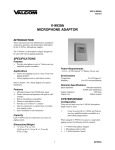
Genelec 1094A and 1092A
Active Subwoofer Systems
Operating
Manual
Genelec 1094A and 1092A Subwoofers
General Description
The Genelec 1094A and 1092A active
subwoofers are powerful low frequency
loudspeakers, incorporating all the
amplifier and crossover electronics
needed to combine them with other
loudspeakers and amplifiers.
B a la n c e d
In p u ts
Drivers
The 1094A contains a single 385mm
(15") long throw cone driver, housed
in a 110 litre vented cabinet. A cavity
over the driver boosts the drivers
efficiency and acoustically attenuates
possible distortion components. The
1092A utilises two 210mm (8") cone
drivers, housed in a 55 litre vented
cabinet, and employs driver front
loading.
S u b
Crossovers
The 3+1 channel active crossover
within the amplifier unit filters the low
and high frequency components of the
three front channels, dividing the input
signals between the subwoofer and
the main monitors. A separate
subwoofer input connector allows for
complete compatibility with digital 5.1
channel surround sound systems.
The crossover filter also provides
calibrated ‘Bass Roll-off’ and ‘Phase’
controls, minimising the effects of the
room on the performance of the
subwoofer.
Amplifiers
The amplifier unit is mounted in the
rear of the cabinet on quick release
vibration isolators to ensure rattle free
operation and long term reliability.
The 1094A and 1092A amplifier output
powers are 400W and 180W
respectively.
The
amplifiers
incorporate special driver protection
circuitry for driver overload protection.
Installation
Each subwoofer is supplied with a
mains cable and an operating manual.
Once unpacked, place the subwoofer
in a suitable position (for more details
see the 'Positioning' section).
C R O S S O V E R
F IL T E R
B a la n c e d
O u tp u ts
H P 8 5 H z
L
L
C
C
R
R
2 7 0 °
S e n s itiv ity
± 6 d B
L P
8 5 H z
B a s s
R o ll- o ff
0 °
1 8 0 °
P o w e r
A m p lifie r
9 0 °
P h a s e
S ta rt/S to p
M u te
D r iv e r
P r o te c tio n
P o w e r s u p p ly
c ir c u its
Figure 1. Functional blocks of Genelec 1094A and 1092A Subwoofers
Before connecting the audio signals,
ensure that both the subwoofer and
the main monitors are switched off.
Check that the subwoofer voltage
selector switch is set to the correct
voltage and that the correct fuse for
that voltage is fitted.
Audio connections to the subwoofer
are made via balanced XLR
connectors. Signals from the source
are fed into the subwoofer input
connectors and signals for the main
monitors are taken from the subwoofer
output connectors. Once all
connections have been made, the
subwoofer and main monitors are
ready to be powered up.
Setting the Input Sensitivity
The subwoofer requires input
sensitivity alignment to the mixing
console or other source to obtain a
correctly balanced system. The input
sensitivity control is located on the
rear panel of the subwoofer. An input
voltage of -6dBu with a -6dBu input
sensitivity setting will produce 100dB
SPL @ 1m. To obtain a 110dB SPL
output an input voltage of +10dBu is
required when the input sensitivity is
set to 0dBu.
Setting the Bass Roll-Off
Switches
The acoustic response of the
subwoofer may have to be matched to
the characteristics of room in which it
will be used. To adjust the subwoofer
to match these characteristics use
the ''Bass Roll-off' control switches
located on the rear panel of the
subwoofer. Table 1 provides some
suggestions for the 'Bass Roll-off'
switch settings. When both roll-off
switches are 'off', a flat anechoic
response results.
Room Type
Flat Anechoic Response
Positioned near a wall
Positioned in a corner
Table 1. Suggested Bass Roll-Off switch settings.
Bass Roll-Off
Sw1 (-2dB)
Sw2 (-4dB)
OFF
OFF
ON
OFF
ON
ON
Subwoofer Positioning
5
2
The figure to the left shows some example subwoofer positions
within a room. Unless mentioned otherwise, the vents of the
subwoofer should face towards the nearest wall.
'Soffit' Mount
1
2
1
2&3
4
4
3
5
3
Recommended position.
Recommended only when using two subwoofers.
This arrangement may cause a loss in low
frequencies if the distance from the listening position
to the front wall is between 1 and 3m.
The 'Soffit' or flush mount is also recommended.
Here the vents must radiate into the room.
Figure 2. Subwoofer positioning
Positioning in the Room
Safety Considerations
Overload Indicators
The placement of the subwoofer in the
room will affect the overall frequency
response of the system as, with low
frequencies, the effects of the room
are more apparent.
The 1094A/92A has been designed in
accordance with international safety
standards. However, to ensure safe
operation and maintain the instrument
under safe operating conditions the
following warnings and cautions should
be observed.
The 1094A contains a red 'Clip' LED.
This indicator is located on the rear
panel of the subwoofer.
The clip LED will light if the amplifier
is overloaded. If this occurs frequently,
reduce the input level to the subwoofer
until the clip LED stops blinking.
The subwoofer radiation ports should
be placed within 1m of a wall. The
amplifier panel should not be positioned
less than 10 cm from a surface, as this
may cause heat dissipation problems
from the amplifier back plate. The
placement will affect the phase
difference between the main monitors
and the subwoofer, and also the bass
roll-off rate. These effects can be
compensated by the use of the controls
in the amplifier unit; but consideration
should be made when placing the
subwoofer.
-
-
-
Servicing and adjustment should
only be performed by qualified
service personnel.
Opening the amplifier's rear panel
is strictly prohibited except by
such persons who are aware of the
hazards involved.
It is forbidden to use this product
with an unearthed mains cable,
which may lead to personal injury.
Warning!
Choose a central and symmetrical
position for the subwoofer as this will
give an even phase match between all
monitor channels. Positioning the
subwoofer close to a corner should be
avoided as it will boost the bass level
at lower frequencies and may cause
asymmetrical spatial imaging.
See the section titled 'Subwoofer
Positioning' for examples of
recommended positions within a room.
This equipment is capable of delivering
sound pressure levels in excess of
85dB, which may cause permanent
hearing damage.
Setting the Phase Control
The effect of incorrect phase alignment
between main monitors and subwoofer
is a drop in the frequency response of
the whole system at the crossover
frequency. The graphs below (figure
3) show the effect of phase difference
on the frequency response.
The phase difference between the
main monitors and subwoofer at the
listening position is dependent upon
the position of the subwoofer in the
listening room. For accurate system
alignment in the room acoustic
measuring equipment is required. If
this equipment is not available to the
user coarse phase matching can be
applied.
Coarse Phase Correction
Method
The method to coarse align the phase
of the system is as follows.
• Connect an audio frequency signal
generator to one of the channels used
in the system. If the signal generator
has an unbalanced output use a cable
with pin 3 grounded to pin 1 at the input
as shown in figure 4 below.
CABLE
2
1
3
RCA
SCREEN
XLR
MALE
Figure 4. XLR to RCA connector for
unbalanced operation.
P h a se D iff ere n c e : 0°
85 Hz
• Set the frequency generator to 85Hz.
If a signal generator is not available
then it is possible to use an audio test
recording with a test frequency in the
range 70Hz to 100Hz.
Connect a high grade measuring
microphone to the analyser and feed
pink noise into the left main monitor.
Position the microphone at the listening
position and adjust the input sensitivity
of the subwoofer until frequencies
below and above 85 Hz are reproduced
with equal level. Then adjust the phase
control switches until a clear dip of at
least -6dB can be seen at the crossover
frequency (85 Hz).
If a dip appears at several switch
positions select the one that gives the
deepest reading. This should be the
case where the phase difference
between the subwoofer and the main
monitors is at a maximum. To change
the phase difference to a minimum the
-180° switch should be moved to the
opposite setting. The frequency
analyser should now show the
smoothest response around 85 Hz
and the phase should now be set
correctly. Repeat the above procedure
with the right channel and possible
centre channel main monitors.
• Finally, set the -180° phase
switch to the opposite setting.
85 Hz
1 2 3 4
1 2 3 4
1 2 3 4
P h a se D iff ere n c e : 18 0 °
• Next toggle the -90° phase
switch 'on' and 'off', and again
set it to the position which
gives the lowest sound level.
ON
85 Hz
ON
P h a se D iff ere n c e : 90 °
ON
Subwoofer Bypass Control
•Toggle the -180° phase
switch 'on' and 'off' and set it
to the position which gives
the lowest sound level at the
listening position.
A bypass control feature is included
into the subwoofer circuits so that the
effect of the subwoofer on the whole
monitor system can be determined.
With the bypass switch on, the high
pass filters for the main monitors are
bypassed and the system behaves as
if the subwoofer were not connected.
The bypass remote controller is
inserted into the ¼ inch jack socket
located on the rear amplifier panel.
See figure 5 for construction details.
Mono ¼inch
Jack Socket
P h a se D iff ere n c e : 27 0 °
Phase Correction Method
with Test Equipment
SPST Switch
85 Hz
Figure 3. The effect of phase difference
between the subwoofer and the main
monitors
If a frequency analyser and a pink
noise generator are available then the
following procedure can be used to
match the phasing between the
subwoofer and the main monitors.
Figure 5. Bypass Remote Switch
Construction.
System Connection
The following diagrams show the
various ways the subwoofer can easily
be included into an existing system.
All connections to the subwoofer should
be of the balanced XLR type to minimise
the noise immunity of the speaker
system. If an unbalanced source has
to be used then an RCA to XLR
connection is required; the electrical
connection diagram is shown in fig. 4.
Subwoofer in two channel
Stereo mode.
Both left and right stereo channels are
fed into the inputs of the subwoofer.
Each subwoofer output is then
connected to the corresponding main
monitor.
Figure 6. One subwoofer in a twochannel system.
Two Subwoofers (stereo) in
two channel Stereo mode.
To combine the two subwoofers into
the system so that they produce stereo
sub-bass signals, connect the system
as shown to the left.
Figure 7. Two subwoofers (stereo) in a
two- channel system.
Two Subwoofers (mono) in
two channel Stereo mode.
To combine the subwoofers into the
system so that they produce mono
sub-bass signals, connect the system
as shown to the left.
Note that the level generated by the
subwoofers will be 6dB greater than
that generated by a single subwoofer,
hence reduce the sensitivity control of
each subwoofer by 6dBu, so that the
level balance is maintained between
the subwoofer and the main monitors.
Figure 8. Two subwoofers (mono) in a
two-channel system
Figure 9.
Subwoofer in an
Analogue Matrix
Surround Sound
system
Subwoofer in Analogue
Matrix Surround Sound
systems.
When using a single subwoofer in an
analogue matrix surround sound
system, such as Dolby Surround or
Dolby Pro-Logic, only the front three
channels should be connected to the
subwoofer inputs (see figure 9 above).
All front channels that are used should
be connected via the subwoofer so
that the output of the subwoofer is
matched to the rest of the system. All
other surround sound channels should
be connected as normal.
If there is a subwoofer channel output
on the decoder it should NOT be
connected to the subwoofer speaker
since the filtering within the decoder
will effect the performance of the
subwoofer.
Figure 10.
Subwoofer in a
digital Discrete
5.1 Surround
Sound system
Subwoofer in Digital
Discrete 5.1 Surround
Sound systems
Digital decoders, for example, Dolby
Digital Surround (AC-3), DTS and
DMAG2, have a discrete subwoofer
channel output which should be
connected to the sub input on the
1092A or 1094A (see figure 10 above).
This enables the subwoofer to correctly
reproduce all the sub-bass information
in the mix. Genelec Subwoofers can
be used to good effect in “Discrete
5.1” system surround channels as
they are wide band.
Digital decoders do not limit the
bandwidth of the rear channels. If
necessary, a second Genelec 1092A
or 1094A subwoofer can be connected
to the rear channels.
Two Subwoofers (stereo) in
three channel LCR mode.
To combine the subwoofers into the
system so that one subwoofer
produces the left and centre bass
signals, whilst the other produces the
right and centre bass signals, connect
the system as shown to the left.
Connection to the centre monitor can
be made from either one of the
subwoofer centre channels outputs.
Note that as above the level sensitivity
is 6dBu different from the single
subwoofer system shown in figures 9
and 10.
Figure 11. Two subwoofers (stereo) in a three-channel system
Two Subwoofers (mono) in
three channel LCR mode.
To combine the subwoofers into the
system so that both subwoofers
produce the bass signals for all three
channels, connect the system as
shown to the left.
Note that the level generated by the
subwoofer will be 6dB greater than
that generated by a single subwoofer.
Hence the sensitivity control of both
subwoofers should be turned down by
6dBu so that the level balance is
maintained between the subwoofer
and the main monitors.
Connection to the centre monitor can
be made from either one of the
subwoofer centre channel outputs.
Figure 12. Two subwoofers (mono) in a three-channel system
Maintenance
Guarantee
Accessories
No user serviceable parts are to be
found within the amplifier unit. Any
maintenance of the unit should only be
undertaken by qualified service
personnel. Ensure that if fuse
replacement is required, only fuses of
the appropriate voltage and current
ratings are used. REMEMBER to
disconnect the power supply by
removing the mains cable before fuse
replacement.
This product is supplied with a ONE
year guarantee against manufacturing
faults or defects that might alter the
performance of the 1094A/1092A unit.
Refer to supplier for full sales and
guarantee terms. (Not applicable in
the United States)
Additional options available :
Bypass switch box
1092-400
1092 Magnetic shielding 1092-403
1094 Magnetic shielding 1094-403
SYSTEM
SPECIFICATIONS
1094A
1092A
Free field frequency response
of system (± 2.5 dB):
29 - 80 Hz
33 - 80 Hz
>120 dB SPL
>115 dB SPL
Maximum short term sine wave
acoustic output in half space,
averaged from 35 Hz to 85 Hz
@ 1m:
Self generated noise level in free
field @ 1m on axis (A-weighted)
< 10 dB
Harmonic distortion at 100 dB SPL
@ 1m on axis in half space
(30...100 Hz):
< 3%
< 4%
385 mm
(15")
2 x 210 mm
(2 x 8")
50 kg
(110 lb)
30 kg
(66 lb)
Height
739 mm
(291/16")
615 mm
(24 3/16")
Width
468 mm
( 18 7/16")
320 mm
(12 5/8")
620 mm
(24 7/16")
510 mm
(201/16")
Drivers:
Weight:
Dimensions:
< 10 dB
Depth
CROSSOVER
SECTION
Subsonic filter (18 dB/octave)
below:
Both Models
29 Hz
Crossover frequency, (sub/main monitors)
Crossover frequency, (sub input channel)
Crossover acoustical slope
Lowpass:
Highpass:
Midband rejection, freq. > 400 Hz:
33 Hz
85 Hz
Full band/85 Hz
from 0 to -6 dB @ 33 Hz
Phase matching control in 90° steps:
from 0° to -270° @ 85 Hz
1094A
1092A
Short term amplifier output
power :
400 W (8 Ohm) 180 W (4 Ohm)
(Long term output power is limited
by driver unit protection circuitry.)
Amplifier system distortion
at nominal output:
THD
SMPTE-IM
CCIF-IM
DIM 100
< 0.08%
< 0.08%
< 0.08%
< 0.08%
< 0.08%
< 0.08%
< 0.08%
< 0.08%
Signal to Noise ratio,
referred to full output:
> 100 dB
> 100 dB
Mains voltage:
100/200 or 115/230V
Voltage operating range:
± 10%
Power consumption (average):
Idle
Full output
60 VA
650 VA
INPUT
SECTION
50 VA
300 VA
Both Models
Input connectors: XLR female.
pin 1: gnd
pin 2: +
pin 3: -
Input impedance:
10 kOhm balanced
Input level for 100 dB SPL
output @ 1m:
variable from +6 to - 6 dBu
OUTPUT
SECTION
Both Models
Output connectors: XLR male.
pin 1: gnd
pin 2: +
pin 3: -
Output impedance:
100 Ohm balanced,
active floating
Gain:
0 dB
28 dB/octave
12 dB/octave
> 50 dB
Bass roll-off control operating
range in 2 dB steps:
Genelec Oy, Olvitie 5
FIN - 74100 IISALMI, FINLAND
Phone: +358 - 17 - 813 311
Telefax: +358 - 17 - 812 267
Web:
www.genelec.com
E-mail: [email protected]
AMPLIFIER
SECTION
Genelec Document DR920021
(1092-0106-3)
COPYRIGHT GENELEC OY 1998
All data subject to change without prior notice