1
Genelec 2029A Digital
Monitoring Speaker
Operating
Manual
2029A Digital Monitoring Speaker
1. General description
Genelec 2029A Digital near field monitor has a digital audio interface allowing you to input the digital audio straight
into the loudspeaker. This has several
significant advantages.
When you are working with a digital
audio workstation or you are processing audio in a modern studio, your signal is digital. The 2029A Digital allows
you to listen to what you have in your
digital format.
The 2029A Digital supports all the
same modes of operation as the analog 1029A. You can use it with a subwoofer. You can use it in surround audio systems. You can even use the
2029A Digital as an analog speaker.
Due to its compact size, integrated
construction, excellent dispersion and
precise stereo imaging, this speaker
system is ideal for near field monitoring, mobile vans, digital audio workstations, broadcast and TV control
rooms, surround sound systems, home
studios, multimedia applications and
also computer soundcards. As an active speaker this unit contains all you
need- drivers, power amplifiers, active
crossover filters and protection circuitry. The Directivity Control Waveguide
(DCW™) technology provides excellent frequency balance even in difficult acoustic environments.
digital audio signal. A higher sampling
rate allows higher frequencies to be
recorded. Studio recording systems
use sampling rates of 44 kHz and
above.
Turning the digital presentation to an
analog signal using a DA converter
involves significant sources of error.
Your digital-to-analog converter may
have inferior performance. It may be
misaligned with your amplifiers. The
interface between the converter and
the amplifier may distort the signal or it
may change the frequency balance.
Your monitoring volume level may
need to be adjusted in the digital domain instead of analog.
Genelec 2029A Digital allows you to
solve all of these problems. The alignment of the whole system right from the
digital input connector is carefully
balanced, to make sure that you hear
the whole digital truth, and nothing but
the truth. All you have to do is to supply
the digital signal, and adjust for the
volume you desire.
The IEC958 or EIAJ CP-340 standards
define one of the most popular digital
audio interfaces in use today, often
called S/P-DIF. It uses the same RCA
connector and interface cables that
most consumer audio equipment use
today. The standard is versatile
enough to be suitable for consumer
use as well as studio audio signal processing. You typically find it on professional digital audio workstations
and high quality sound cards.
2. Digital Audio
The quality of a digital audio signal is
defined by the two parameters: word
length and sampling rate.
The word length defines how precisely the audio signal is represented.
Longer word length leads to smaller
noise and distortion level. The typical
word length in CD records is 16 bits.
Studio recording systems use word
lengths of 20 bits and above.
The sampling rate determines what frequencies can be represented in the
3. Integrated Constr
uction
Construction
As the digital interface and amplifiers
are built into the speaker enclosure,
the only connections required are the
mains supply and the digital input signal, making the 2029A Digital very easy
to set up and use.
Digital interface
The digital audio interface comprises
a digital audio receiver and a digitalto-analog converter (DA converter).
The digital input accepts an S/P-DIF
digital audio signal having a word
length up to 24 bits and sampling rate
up to 55 kHz.
The DA converter has an interpolator
increasing the internal sampling rate
to four times the original, before interpolation to 128 times the original sampling frequency in a fourth order deltasigma modulator, and digital-to-analog conversion in a switched capacitor integrator and an analog low-pass
filter. This conversion process has high
resilience to clock jitter and excellent
linearity.
Drivers
The bass frequencies are reproduced
by a 130 mm (5") bass driver mounted
in a 4.5 litre vented cabinet. The -3 dB
point lies at 68 Hz and the frequency
response extends down to 65 Hz
(-6 dB).
The high frequency driver is a 19 mm
(3/4") metal dome. Uniform dispersion
is achieved with the revolutionary
DCW™ Technology pioneered by
Genelec.
Magnetic shielding is standard on
Genelec 2029A Digital. Shielding is
vital for applications such as video post
production, where stray magnetic
fields must be minimized.
Crossover
The active crossover network is acoustically complementary and the slopes
are 24 - 32 dB/octave. The crossover
frequency is 3.3 kHz. The room response controls ('treble tilt', 'bass tilt'
and 'bass roll-off') allow perfect reproduction in any room installation.
Amplifiers
The amplifier unit is built inside the
speaker enclosure. The bass and treble amplifiers both produce 40 W of
output power. The fast, low distortion
amplifiers are capable of driving a stereo pair to peak output sound pressure
levels in excess of 110 dB at 1 m. The
unit incorporates special circuitry for
driver overload protection.
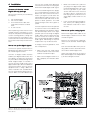
4. Installation
Contents of Genelec 2029A
Digital delivery package
Please make sure that you can identify
these parts.
1. Two loudspeakers
2. Two mains cables.
3. One interconnect cable, with
male XLR connectors on both
ends.
4. A user manual
After unpacking, check that the mains
voltage selector (see figure 2) is correctly set and place the loudspeakers
at their listening position, taking note
of the listening axis (see figure 1). Ensure that the mains switches are off and
the volume controls fully counter-clockwise.
How to set up for digital signals
Connect the special interconnect cable between the XLR connectors of the
two 2029A Digital monitors.
Connect an digital audio interface
cable to your digital audio source. You
can identify the right RCA connector
on your audio source by looking for the
words “Digital Output” or “S/P-DIF”. If
you are sure your audio source has a
digital audio output, but the cable does
not fit the connector, you may have an
equipment that is using a BNC connector instead of the standard RCA.
You can find interface plugs that convert the BNC to an RCA. Before you
Figure 1: 2029A outer dimensions, with the
reference axis between the bass and the
treble drivers.
use one you should make absolutely
sure that the connector is carrying the
IEC958 formatted digital audio signal.
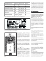
One of the 2029A Digital units (Right)
has a matching RCA connector in the
back of the unit. Locate the RCA connector (see figure 2) and notice the
signal indicator LED in the front. Connect the RCA cable and switch on the
power on both speakers. The LED
should change colour from green to
yellow.
Turn the output level at the left speaker
to maximum value. This calibrates the
balance between the speakers. Adjust
the desired output level at the right
speaker (the one receiving the digital
audio). Note that the output level adjustment scales the maximum sound
pressure level produced by the digital
audio signal. Monitoring at very low
output levels may not be accurate.
To help you solve any problems, here
are a few pointers.
•
•
Make sure that your audio signal
source has been set to transmit the
audio to the S/P-DIF output.
Make sure the digital interface cable is properly connected at both
ends.
Figure 2: 2029A Digital Right speaker backpanel
•
Make sure the LED turns yellow as
you plug in the digital audio cable
to the 2029A Digital unit. If this is not
the case, go back to your audio
source and check once more that
the right output is selected. If the
LED stays green you do not have a
valid digital audio carrier on the
cable.
•
If you see the LED flashing red colour, check your cabling. Red colour indicates a bit error in transmission.
How to set up for analog signals
Remove the digital audio cable at the
2029A Digital. Observe that the LED
should turn green.
Remove the interconnect cable between the two Genelec 2029A Digital
units.
Run normal XLR cables from your analog audio source to the XLR connectors on both 2029A Digital units.
Adjust the output levels at the front of
both 2029A Digital units independently for left and right channels.
How to set up Genelec 1091A
subwoofer
A standard Genelec 1091A subwoofer package contains cables to connect
to both 2029A Digital units. The cables
have 1/4" (6mm) plugs that connect to
the 2029A Digital units (see figure 5).
On each 2029A Digital, flip the tone
control switch number 2 to "ON" position. This is the right setting when the
subwoofer 1091A is used.
Setting tone controls
Figure 3. Cabling scheme for digital setup
The response of the system may have
to be adjusted to match the acoustic
environment. The adjustment is done
by setting the tone control switches on
the rear panel. The tone control has
four switches and can adjust 'treble tilt',
'bass tilt' and 'bass roll-off.' The factory settings for these are 'ALL OFF' to
give a flat anechoic response. See
Figure 6 for suggested tone control
settings in differing acoustic environments. Figure 8 shows the effect of the
controls on the anechoic response.
Always start adjustment by setting all
switches to 'OFF' position. Then set a
switch to 'ON' position to select the
necessary response curve.
5. Monitor placement.
Console top mounting.
Figure 4. Cabling scheme for analog setup
Avoid mounting Genelec 2029A Digital monitors directly on the console top.
Instead, position the speakers slightly
behind the console by using floor
stands, wall mounts or microphone
stands. This minimizes sound colouring reflections from the console surface.
Room placement.
To produce a true and accurate stereo
image the monitors must have exactly
similar frequency responses. When
placed in a room monitor responses
change due to reflections of the sound
waves from the room’s boundaries. It
is necessary to place the monitors at
the same height and also at the same
distance from the front and side walls
so that reflections, and therefore
changes to the frequency response,
are similar.
To avoid differences in frequency responses due to reflections from the
Figure 5. Cabling and 2029A tone control settings when using subwoofer 1091A.
Speaker Mounting Position
Treble Tilt
(Switch 1)
Bass Tilt
(Switches 3 & 4)
Bass Roll-Off
(Switch 2)
Flat Anechoic Response
OFF
OFF
OFF
Free standing in a damped room
OFF
OFF
OFF
Free standing in a reverberant
room
OFF
-2dB (Switch 3 ON,
switch 4 OFF)
OFF
Near field on a console bridge
OFF
-4dB (Switch 4 ON,
switch 3 OFF)
OFF
Near to a wall
OFF
-6 dB (Switches 3
and 4 ON)
OFF
With the 1091A subwoofer
See above
settings
See above
settings
ON
be used in conjunction with the wall
hanging key holes. The 2029A Digital
can be placed horizontally or vertically. Enclosed is also a bag containing
four large and four small friction pads.
The larger pads are for the base of the
2029A Digital, and if placed horizontally, the smaller pads may be used on
the side. There are recesses on the
speaker cabinet where the pads fit.
6. Maintenance
Figure 6. Suggested tone control settings for various acoustic environments
There are no user serviceable parts are
in the unit. Maintenance or repair of the
2029A Digital units should be done by
qualified service personnel only.
7. Safety Considerations
The 2029A Digital has been designed
in accordance with international safety standards. To ensure safe operation
and to maintain the instrument in safe
operating condition, the following
warnings and cautions must be observed:
Servicing and adjustment should only
be performed by qualified service personnel.
Figure 7. Tone control switches on the back panel of 2029A Left. Note that the digital audio
receiving speaker (Right) has different labelling.
front wall, the monitors should be
placed either nearer than 1m or further
than 3m from the front wall. Placement
close to the front wall (<1m) will boost
low frequencies, and the tone controls
should be adjusted appropriately (see
figure 6).
The monitors should be aimed toward
the listening position. This maximizes
the ratio of direct sound to reflected
sound and the listener is able to hear
more of the material and less of the
room effects. Subjectively this is perceived as cleaner sound and superior
stereo imaging.
Mounting Options
Figure 8. Mounting options of the 2029A
Digital
Figure 8 shows the three possibilities
for mounting the 2029A Digital. On the
base of the monitor is a 3/8" UNC threaded hole which accommodates a standard microphone stand. On the rear
there are two methods to suspend the
loudspeaker. An Omnimount® size 50
bracket can be used, two M6x10 mm
screws are required. 4 mm diameter
screws with suitable size heads can
Do not use this product with an unearthed mains cable as this may compromise electrical safety.
This equipment is capable of producing sound pressure levels in excess of
85 dB, which may cause permanent
hearing damage.
Free flow of air behind the loudspeaker is necessary to maintain sufficient
cooling. Do not obstruct airflow around
the loudspeakers.
Do not insert any objects through the
bass reflex ports on the face of the unit,
as this may damage the electronics inside the loudspeaker.
Do not run an analog audio signal to
the digital input RCA connector. Doing so may overload your audio equipment output and cause them permanent damage.
8. Guarantee
This product is guaranteed for a period of ONE year against faults in materials or workmanship. Refer to supplier
for full sales and guarantee terms.
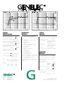
Figure 9:
The effect of 'treble tilt', 'bass tilt' and 'bass roll-off' controls in free field.
SYSTEM
SPECIFICATIONS
Lower cut-off frequency, -3 dB:
< 68 Hz
Upper cut-off frequency, -3 dB:
> 20 kHz
Figure 10: Horizontal directivity characteristics and power response of 2029A Digital
in its vertical configuration measured at 1m in free field.
CROSSOVER
SECTION
DIGITAL
SECTION
Inputs:
Word length:
24 bits
Input format:
IEC958, S/P-DIF, EIJAC CP-340
Input 1: XLR female, balanced 10 kOhm
Input 2: 1/4 " Jack socket, balanced 10 kOhm
Free field frequency response of system:
70 Hz - 18 kHz (± 2.5 dB)
Volume control:
Variable from Mute to -6 dBu for 100 dB SPL
output @ 1m
Maximum short term sine wave acoustic output on axis
in half space, averaged from100 Hz to 3 kHz:
@ 1m
> 100 dB SPL
@ 0.5m
> 106 dB SPL
Subsonic filter below 68 Hz :
18 dB/octave
Maximum long term RMS acousticoutput in same
conditions with IECweighted noise (limited by driver unit
protection circuit):
@ 1m
> 98 dB SPL
@ 0.5m
> 104 dB SPL
Maximum peak acoustic output per pair on top of
console,
@ 1 m from the engineer with music material:
Harmonic distortion at 85 dB SPL @ 1m on axis:
Freq:
75...150 Hz
< 3%
> 150 Hz
< 1%
Drivers:
Bass
130 mm (5") cone
Treble
19 mm (3/4") metal dome
Both drivers are magnetically shielded.
Weight:
5.7 Kg
(12.5 lb)
247 mm
151 mm
191 mm
(9 3/4")
( 515 /16")
(7 1/2")
Dimensions:
Height
Width
Depth
Input sampling rate:
75 ohms
25-55 kHz (no de-emphasis)
44.1 and 48 kHz (using
de-emphasis)
Jitter resiliance:
0.15 unit intervals
1091A Subwoofer output (input 2) at 100db SPL:
-23 dBu into 33kOhm load
Dynamic range:
>101 dB (A weight, triangular
PDF dither, 20 bit data)
Ultrasonic filter above 25 kHz:
12 dB/octave
De-emphasis:
50/15us, automatic
Recovered clock jitter:
200 picoseconds RMS typical
Crossover frequency, Bass/Treble:
3.3 kHz
Crossover acoustical slopes:
24 - 32 dB/octave
Treble tilt control operating range:
0 to -2 dB @ 15 kHz
AMPLIFIER
SECTION
Bass roll-off control operating in a -6 dB step @ 85 Hz
(to be used in conjunction with the 1091A subwoofer)
Bass amplifier output power with an 8 Ohm load:
40 W
Bass tilt control operating range in -2 dB steps:
0 to -6 dB @ 150 Hz
Treble amplifier output power with an 8 Ohm load:
40 W
The 'CAL' position is with all tone controls set to 'off'
and the input sensitivity control to maximum (fully
clockwise).
Long term output power is limited by driver unit
protection circuitry.
> 110 dB
Self generated noise level in free field @ 1m on axis:
< 10 dB
(A-weighted)
Input termination impedance:
Amplifier system distortion at
nominal output:
THD
SMPTE-IM
CCIF-IM
DIM 100
<
<
<
<
0.08%
0.08%
0.08%
0.08%
Signal to Noise ratio, referred to full output:
Bass
> 90 dB
Treble
> 90 dB
Mains voltage:
100/200 or 115/230 V
Voltage operating range:
±10%
Power consumption:
Idle
Full output
Genelec Oy, Olvitie 5
FIN - 74100 IISALMI, FINLAND
Phone:
+358 - 17 - 83881
Telefax:
+358 - 17 - 812267
Web:
http://www.genelec.com
E-mail:
[email protected]
9 VA
90 VA
Genelec document DR29101
COPYRIGHT GENELEC OY 1998
All data subject to change without prior notice