1
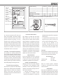
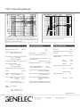
1031A
Operating Manual
Genelec 1031A
Monitoring System
EC Declaration of Conformity
This is to certify that the Genelec Monitoring
System 1031A conforms to the following product
specifications:
Safety:
EMC:
EN 60065
EN 55013, EN 55020,
EN 61000-3-2 and EN 61000 3-3
The product herewith complies with the requirements of The Low Voltage Directive73/23/EEC
and EMC Directive 89/336/EEC as amended by
Directive 93/68/EEC
Signed:
Position:
Date:
Ilpo Martikainen
Managing Director
20-Sep-2001
Genelec 1031A Monitoring System
System
The bi-amplified GENELEC 1031A is a two
way active monitoring speaker designed to
produce high SPL output, low coloration and
broad bandwidth in a small cabinet size. The
1031A is ideal for applications where space
is at premium such as Near Field monitoring,
mobile vans, broadcast and TV control rooms,
surround sound systems and budget and
home studios. Designed as an active speaker,
the 1031A contains drivers, power amplifiers,
active crossover filters and protection circuitry.
The Directivity Control Waveguide™ (DCW™)
technology used provides excellent frequency
balance even in difficult acoustic environments.
Drivers
The low frequencies are reproduced by a
210 mm (8”) bass driver loaded in a 15 liter
vented cabinet. The -3 dB point lies at 47 Hz
and the frequency response extends down to
43 Hz (-6 dB).
The high frequency driver is a 19 mm
(3/4”) metal dome. Uniform dispersion control is achieved with the innovative DCW
Technology pioneered by Genelec, which
also provides perfect phase and delay uniformity at the crossover frequency.
Both drivers are magnetically shielded.
Crossover
The active crossover network consists of
two parallel bandpass filters. Acoustically,
the filters are complementary and the slopes
are 24 dB/octave. The crossover frequency
is 2.2 kHz. The active crossover controls
(‘treble tilt’, ‘bass tilt’ and ‘bass roll-off’) allow
this speaker to be exactly matched to any
room environment.
Amplifiers
The amplifier unit is mounted to the rear
of the speaker enclosure on quick release
vibration isolators, to ensure rattle free
operation and long term reliability. The bass
and treble amplifier produce respectively 120
Watts of short term power. The peak output
sound pressure level of the 1031A exceeds
120 dB at 1 m. The unit incorporates special
circuitry for driver overload and amplifier
thermal overload protection. Variable input
sensitivity allows for accurate level matching
to console output section.
Installation
Each 1031A monitor is supplied with a
mains cable and an operating manual.
After unpacking, place the speaker so that
its acoustical axis (see figure 2) is aimed
towards the listening position. Do not place
the speaker in a horizontal position as this
may cause acoustical cancellation problems
around the crossover frequency.
Sufficient cooling for the amplifier must
be ensured if the speaker is installed in a
restricted space such as a cabinet or integrated into a wall structure. The minimum
clearance for the amplifier is 10 centimeters
(4") to any object. The space adjacent to the
amplifier must either be ventilated or sufficiently large to dissipate heat so that the
ambient temperature does not rise above 35
degrees Celsius (95°F).
Before connecting up, ensure that the
mains switch is off (see figure 4). Check
that the mains voltage selector is correctly
set (Models sold in Europe have a fixed 230
V setting). Audio input is via a 10 kOhm balanced XLR connector, but unbalanced leads
may be used as long as pin 3 is grounded
to pin 1 of the XLR (see figure 3). Once the
connection has been made, the speakers are
ready to be switched on.
Setting the input sensitivity
The input sensitivity of the speakers can be
matched to the output of the mixing console,
or other source, by adjusting the input sensitivity control on the rear panel (see figure 4).
A small screwdriver is needed for the adjustment. The manufacturer’s default setting for
this control is -6 dBu (fully clockwise) which
gives an SPL of 100 dB @1m with -6 dBu
input level. Note that to get the full output
level of 110 dB SPL, an input level of +4dBu
is needed in this setting.
Setting tone controls
The response of the system may also have
to be adjusted to match the acoustic environment. The adjustment is done by setting
Speaker Mounting
Position
TREBLE TILT
CONTROL
TREBLE TILT
dB
BASS TILT
CONTROL
BASS ROLL-OFF
CONTROL
INPUT SENSITIVITY
CONTROL
INPUT
CONNECTOR
OFF
ON
OFF
ON
OFF
ON
+2
-2 dB
-4
MUTE
USING THE TONE
CONTROLS
BASS TILT
dB
+2
0
-2
-4
ALL OFF
4kHz
ALL OFF
0
-2
-4
-6
20kHz
REFER TO THE OPERATING
MANUAL FOR SUGGESTED
TONE CONTROL SETTINGS.
20Hz
600Hz
-2
-4 dB
-6
MUTE
BASS ROLL-OFF
-2
-4 dB
-6
-8
+6
+4
+2
dBu
0
-6
-2
-4
dB
INPUT SENSITIVITY
REQUIRED FOR 100dB
SPL@1m. REFER TO
OPERATING MANUAL
FOR MAXIMUM SPL.
FOR ACCURATE
OPERATION ONLY ONE
SWITCH IN EACH TONE
CONTROL GROUP SHOULD
BE ON AT A TIME.
FOR A FLAT FREE FIELD
RESPONSE SET ALL TONE
CONTROLS TO OFF.
ALL OFF
0
-2
-4
-6
-8
20Hz
100Hz
INPUT SENSITIVITY
CAL POSITION
ALL CONTROLS : OFF
INPUT SENSITIVITY : -6dBu
2
Bass tilt
Bass roll-off
Flat anechoic response
None
None
None
Free standing in a damped room
None
-2 dB
None
Free standing in a
reverberant room
None
-4 dB
-2 dB
Near field or console bridge
None
-4 dB
-4 dB
In a corner
None
-4 dB
-4 dB
Table 1. Suggested tone control settings in some typical situations
PIN 1 = GROUND
PIN 2 = + INPUT
PIN 3 = - INPUT
3
Treble tilt
1
SIGNAL INPUT
MAINS
VOLTAGE
SELECTOR
MAINS INPUT
50 / 60 Hz
150 Watts
115 / 230 V
GENELECR
˜
MAINS CONNECTOR
1031A BI-AMPLIFIED MONITORING SYSTEM
495 mm
MAINS VOLTAGE
SELECTOR
(WHERE
APPLICABLE)
MAGNETICALLY SHIELDED
f
ON
MADE IN FINLAND
SERIAL
NUMBER
MAINS SWITCH
WARNING
Cable
ELECTRIC SHOCK HAZARD!
IT IS FORBIDDEN TO UNDO ANY SCREWS ON THIS EQUIPMENT. SERVICING AND ADJUSTMENT
MUST ONLY BE CARRIED OUT BY QUALIFIED SERVICE PERSONNEL.
NEVER OPERATE THIS EQUIPMENT WITHOUT A PROPER EARTHED MAINS CONNECTION.
DISCONNECT THE MAINS INPUT BEFORE REPLACING THE FUSE.
RCA
(Source)
290 mm
THIS EQUIPMENT IS CAPABLE OF PRODUCING SOUND PRESSURE LEVELS IN EXCESS OF 85dB
WHICH MAY CAUSE PERMANENT HEARING DAMAGE.
29
0m
m
ENSURE THAT THE CORRECT VOLTAGE AND APPROPRIATE FUSE ARE SELECTED BEFORE
CONNECTING TO THE MAINS SUPPLY.
Screen
XLR
(Speaker)
320 mm
Figure 1. Amplifier panel layout of the 1031A
the three tone control switch groups ‘treble
tilt’, ‘bass tilt’ and ‘bass roll-off ’ on the rear
panel of the amplifier. The factory settings
for these controls are ‘All Off ’ to give a flat
anechoic response. See Table 1 for suggested tone control settings. Figure 5 shows
the effect of the controls on the anechoic
response. Always start adjustment by setting
all switches to ‘OFF’ position. Then set only
one switch to the ’ON’ position to select the
response curve needed. If more than one
switch is set to ‘ON’ (within one switch group)
the attenuation value is not accurate.
Vertical / horizontal mounting
The speakers are normally delivered set
up for vertical mounting. Horizontal mounting should be avoided due to the increased
likelihood of early reflections that degrade
the the direct sound. If horizontal mounting
is needed the DCW plate may be rotated so
that the Genelec logo remains horizontal by
removing the four corner screws of the DCW
and carefully lifting and turning the DCW.
Console top mounting
If the 1031A’s are used for near field monitoring, avoid mounting them on the meter bridge
of the console. Instead position the speakers
slightly behind the console by using floor
stands or wall mounts. This prevents the
first reflections from the console surface from
coloring the sound.
Figure 2. Location of the acoustic axis
Overload indicators
The speaker is provided with two status
LED's marked 'OVL' and 'ON'. The green
ON-LED when lit indicates that the speaker
is ready for use. The red OVL-LED indicates
that the amplifier is overloaded or the driver
protection circuit is activated. In both cases
reduce the signal level so that the LED stops
blinking. If the OVL-LED stays on constantly it
indicates that the amplifier thermal protection
is activated. Let the amplifier cool down and
check that the ventilation at the rear side of
the speaker is not blocked. There should be
a clearance of more than 4" (10cm) between
speaker rear and any solid surface.
Maintenance
No user serviceable parts are to be found
within the amplifier unit. Any maintenance
or repair of the 1031A unit should only be
undertaken by qualified service personnel.
Safety considerations
Although the 1031A has been designed
in accordance with international safety
standards, to ensure safe operation and to
maintain the instrument under safe operating
conditions, the following warnings and cautions must be observed:
1. Servicing and adjustment must only
be performed by qualified service
personnel. The amplifier’s rear panel must
not be opened.
Figure 3. RCA to XLR cable
2. Do not use this product with an
unearthed mains cable as this may lead to
personal injury.
3. To prevent fire or electric shock, do not
expose the unit to water or moisture. Do
not place any objects filled with liquid,
such as vases on the speaker or near it.
4. Note that the amplifier is not
completely disconnected from the AC
mains service unless the mains power
cord is removed from the amplifier or the
mains outlet.
WARNING!
This equipment is capable of producing sound
pressure levels in excess of 85 dB, which
may cause permanent hearing damage.
Accessories
Protective grille
Wall mount
Floor stand
Order code
1031-409
1031-404-V/H*
1031-405-V/H*
*State the desired speaker orientation
V=vertical or H=horizontal when ordering
these accessories.
Guarantee
This product is supplied with one year guarantee against manufacturing faults or defects
that might alter the performance of the 1031A
unit. Refer to supplier for full sales and guarantee terms.
1031A Operating Manual
AUDIO PRECISION 1031anec LEVEL(dBr) vs FREQ(Hz)
100
07 SEP 93 11:21:58
AUDIO PRECISION 1031anec LEVEL(dBr) vs FREQ(Hz)
07 SEP 93 10:04:11
110
95
105
0°
90
100
15°
85
95
80
90
30°
75
BASS TILT
85
45°
70
80
65 100
75
60 95
70
90
65
20
100
1k
10k
60
20k
Figure 4. The upper curve group shows the horizontal directivity
characteristics of the 1031A in vertical configuration measured at 1 m.
The lower curve is a 1/3 octave band power response, measured in an
IEC approved reverberation chamber.
SYSTEM SPECIFICATIONS
Lower cut-off frequency, -3 dB:
Upper cut-off frequency, -3 dB:
BASS ROLL-OFF
20
1k
100
Free field frequency response of system:
48 Hz - 22 kHz (± 2 dB)
Maximum short term sine wave acoustic output on
axis in half space, averaged from 100 Hz to 3 kHz:
@ 1m > 110 dB SPL
@ 0.5m > 116 dB SPL
Maximum long term RMS acoustic output in same
conditions with IEC weighted noise (limited by
driver unit protection circuit):
@ 1m > 101 dB SPL
@ 0.5m > 107 dB SPL
Maximum peak acoustic output per pair above
console top, @ 1 m from the engineer with music
material:
> 120 dB
Input connector XLR female:
Input impedance:
10k
20k
Figure 5. The curves show the effect of the bass tilt, treble tilt and
bass roll-off controls on the free field response.
AMPLIFIER SECTION
CROSSOVER SECTION
< 47 Hz
> 22 kHz
TREBLE TILT
pin 1 gnd
pin 2 +
pin 3 -
10 kOhm balanced
Bass amplifier short term output power with a
8 Ohm load:
120 W
Treble amplifier short term output power with an
8 Ohm load:
120 W
Input level for 100 dB SPL output @ 1m:
variable from +6 to -6 dBu
Long term output power is limited by driver unit
protection circuitry.
Input level for maximum short term sine wave output
of 110 dB SPL @ 1m:
variable from +16 to +4 dBu
Amplifier system distortion at nominal output:
THD
< 0.05%
SMPTE-IM
< 0.05%
CCIF-IM
< 0.05%
DIM 100
< 0.05%
Subsonic filter below 45 Hz :
Ultrasonic filter above 25 kHz:
18 dB/octave
12 dB/octave
Crossover frequency, Bass/Treble:
Crossover acoustical slopes:
2.2 kHz
24 dB/octave
Signal to Noise ratio, referred to full output:
Bass
> 100 dB
Treble
> 100 dB
Treble tilt control operating range in 2 dB steps:
from +2 to -4 dB & MUTE
Mains voltage:
Self generated noise level in free field @ 1m
on axis:
< 10 dB (A-weighted)
Bass roll-off control operating range in 2 dB steps:
from 0 to -8 dB @ 40 Hz
Voltage operating range:
±10%
Harmonic distortion at 90 dB SPL @ 1m on axis:
Freq:
50...100 Hz
< 3%
> 100 Hz
< 0.5%
Bass tilt control operating range in 2 dB steps:
from 0 to -6 dB @ 80 Hz
& MUTE
Power consumption: Idle
Full output
30 VA
160 VA
Drivers:
The 'CAL' position is with all tone controls set to 'off'
and the input sensitivity control to maximum (fully
clockwise).
Bass 210 mm (8") cone
Treble 19 mm (3/4") metal dome
Both drivers are magnetically shielded.
230, 100/200 or 115/230V
according to region
Weight:
12,7 kg (28 lb)
Dimensions:
Height 393 mm (15 1/2")
Width
250 mm ( 9 7/8")
Depth 290 mm (11 7/16")
www.genelec.com
Genelec Document D1031AR001 Copyright Genelec Oy 6.2003. All data subject to change without prior notice
International enquiries:
In the U.S. please contact:
In China please contact:
Genelec, Olvitie 5
Genelec, Inc., 7 Tech Circle
Genelec China Representative Office
FIN-74100, Iisalmi, Finland
Natick, MA 01760, USA
Soho New Town, 88 Jianguo Road
Phone +358 17 83881
Phone +1 508 652 0900
D-1504, Chaoyang District
Fax +358 17 812 267
Fax +1 508 652 0909
Beijing 100022, China
Email [email protected]
Email [email protected]
Phone +86 10 8580 2180
Fax +86 10 8580 2181