1
MicroGate™ Online Kitchen™ Gateway
User Guide
MG1-1000
January 2005
Part Number: 4911000-010
Revision Number: A3
MicroGate™ User Manual
1
TABLE OF CONTENTS
I.
INTRODUCTION............................................................................................................................... 3
II.
FEATURES AND SPECIFICATIONS............................................................................................. 5
ARCHITECTURE .......................................................................................................................................... 5
SERIAL INTERFACE PORT #1 AND PORT #2 ................................................................................................. 5
NETWORK INTERFACE ................................................................................................................................ 5
NAFEM DATA PROTOCOL MIB COMPATIBILITY ....................................................................................... 5
POWER ....................................................................................................................................................... 5
ENVIRONMENTAL ....................................................................................................................................... 6
PHYSICAL SPECIFICATIONS......................................................................................................................... 6
WARRANTY ................................................................................................................................................ 6
III. HARDWARE DESCRIPTION.......................................................................................................... 7
LED INDICATORS ....................................................................................................................................... 8
POWER CONNECTORS PIN ASSIGNMENT ..................................................................................................... 8
RS232 SERIAL PORT PIN ASSIGNMENT ...................................................................................................... 9
RS485 SERIAL PORT PIN ASSIGNMENT ...................................................................................................... 9
ETHERNET (RJ45) CABLE SPECIFICATIONS AND PIN ASSIGNMENTS ......................................................... 11
IV.
INSTALLATION AND CONFIGURATION................................................................................. 12
SYSTEM REQUIREMENTS .......................................................................................................................... 12
CONNECT THE SYSTEM ............................................................................................................................. 12
Basic Installation Procedure .............................................................................................................. 12
Basic Network Configuration Procedure............................................................................................ 13
V.
PART NUMBER SELECTION....................................................................................................... 16
VI.
LIMITED WARRANTIES .............................................................................................................. 17
MicroGate™ User Manual
2
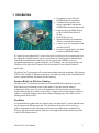
I. Introduction
•
•
•
•
•
•
•
Everything you need for full
NAFEM protocol compliance
Translates and organizes your
legacy equipment's data into the
NAFEM Data Protocol framework
Supports all of the MIBs defined
by the NAFEM Data Protocol
Group
Built-In Web Server
Optional Modem for installations
without a network infrastructure
Connect up to 253 equipment with
one MicroGate™
Firmware Upgradeable in the field
as protocol standards change
E-Control Systems MicroGate™ is one of the most cost-effective and versatile gateways
for adding the NAFEM (North America Association of Food Equipment Manufactures)
Data Protocol and Ethernet connectivity into any equipment. Whether you're an
equipment manufacturer, systems integrator, or IT manager, the cost, functionality, and
flexibility of the MicroGate™ makes it the ideal product for any Online Kitchen™
application.
The MicroGate™ incorporates all essential networking functions including a full-featured
TCP/IP stack, 10Base-T Ethernet connection, real-time operating system, embedded Web
Server, optional modem, and battery-backed memory.
Feature-Rich Cost-Effective Solution
The MicroGate™ incorporates the latest in Flash and SDRAM technology to give the
best feature/price/performance ratio on the market. Using the latest in memory
technologies allows up to 253 pieces of equipment to be connected to one MicroGate,
further reducing the cost of the overall system. Complex menu recipe changes, firmware
updates, or set point changes can be done without disrupting any of the other services
running on the MicroGate™.
Flexibility
As the demand for updates and new features arise, the MicroGate™ can be updated from
any location on the Ethernet network. This eliminates the need to call for service or
replace the hardware itself. All updates and features are added using a standard Web
Browser, like Microsoft® Internet Explorer, or through bulk transfer facilities specified
in the NAFEM data protocol.
MicroGate™ User Manual
3
Total Online Kitchen™ Solution Package
Coupled with E-Control Systems' enterprise Raptor Web Software™, equipment
manufacturers, systems integrators, and IT professionals have a total Online Kitchen™
system to help manage a fully integrated restaurant. Never before has there been such a
synergy between all aspects of the restaurant.
MicroGate™ User Manual
4
II. Features and Specifications
Architecture
CPU: Advanced High Performance Motorola 32-bit embedded PowerPC™ Network
Processor with 66 MIPS at 50 MHz
Memory: 16 Mbytes of SDRAM (expandable to 64 Mbytes)
2 Mbytes of Flash (expandable to 16 Mbytes)
512 Kbytes of battery-backed SRAM (optional)
Real time clock with battery backup
Serial Interface Port #1 and Port #2
Interface Type: CMOS, RS232, or RS485
Data Rates: 300 to 115.2 kbps
Characters: 7 or 8 bits
Stop Bits: 1 or 2
Control Signals (for CMOS and RS232 only): RTS, CTS, DTR, DSR, and DCD
Protocols: MODBUS ™RTU, MODBUS ™ASCII, BACNET , or any custom
proprietary protocol
®
Network Interface
Interface: 10Base-T Ethernet (IEEE 802.3)
Connector: RJ45
Protocols: TCP, UDP, IP, DHCP, BOOTP, ICMP, IGMP, ARP, PPP, SNMP,
SMTP, FTP (client and server), TFTP (client and server), HTTP, and
TELNET
NAFEM Data Protocol MIB Compatibility
Administration
Asset Management
Bulk Transfer
Clock Calendar
Inventory Management
Maintenance
Monitor (with history)
Notify
Security
Traps
Utility
Power
Input Voltage: 5VDC +/-5%
Without Modem:
Input Current (25 MHz Clock): 330mA max
Input Current (50 MHz Clock): 450mA max
MicroGate™ User Manual
5
With Modem:
Input Current (25 MHz Clock): 490mA max
Input Current (50 MHz Clock): 610mA max
Environmental
Operating: 0 C to 70 C (32 F to 158 F)
Storage: -40 C to 85 C (-40 F to 185 F)
Humidity: Maximum 95% Relative Humidity, non-condensing
Altitude: 10,000 ft (3048 m) max
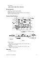
Physical Specifications
TOLERANCES
.010 Inches
4701000A1
Figure 1
Without Modem:
Dimensions: 4.75x3.00x0.80 inches (120.7x76.2x20.4 mm)
Weight: 3.1 oz (88 grams)
With Modem:
Dimensions: 4.75x3.00x1.09 inches (120.7x76.2x27.7 mm)
Weight: 3.3 oz (94 grams)
Warranty
1-year limited warranty
MicroGate™ User Manual
6
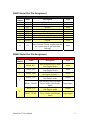
III. Hardware Description
The MicroGate™ is meant to be connected between a local network/internet (using the
LAN Port) and the equipment(s) (using any of the serial interfaces). The MicroGate™
also includes 4 LED indicators to simplify installation and network troubleshooting. The
following figure shows the components/connectors of the gateway:
DS1 DS2 DS3 DS4
J10
J13
J11
J1
MODEM
(OPTIONAL)
J12
2
J14
1
J9
J2
2
BATTERY
(OPTIONAL)
1
J8
1
E1
+
E2
J3
2
J4
1
2
1
J5
2
1
J6
2
J7
2
1
1
Figure 2
Designator
J1
J2
J3
J4
J5
J6
J7
J8
J9
J10
J11-J14
DS1-DS4
Table 1 - Component List
Item
Description
10 MBit Ethernet Port (RJ45). Connects
LAN/Ethernet Port
gateway to the Internet, LAN, or WAN.
Modem Port (RJ11). Connects gateway
Modem Port (Optional)
to the Internet or an external PC using a
telephone line (Optional)
Power Connector
Supplies +5V power to board
RS232 Serial Ports #1
RS232 Levels for Serial Port #1
3.3V TTL Serial Port #1
3.3V TTL Levels for Serial Port #1
3.3V TTL Serial Port #2
3.3V TTL Levels for Serial Port #2
RS485 Serial Port #1 and #2 RS485 Levels for Serial Port #1 and #2
Do not connect. Used for future
Do Not Connect
expansion
RS232 Serial Ports #2
RS232 Levels for Serial Port #2
Do not connect. Used for factory
Do Not Connect
programming
Modem
Used to connect optional Modem Module
Diagnostic LEDs
Used for installation and troubleshooting.
MicroGate™ User Manual
7
LED Indicators
Table 2 - LED Indicators
Name
Condition
Designator
DS1
Link (green)
DS2
Activity (green)
DS3
Heartbeat (green)
DS4
Power (green)
Status
The Ethernet Port
has established a
On
valid network
connection
Network
connection does
Off
not exist, or bad
cable.
The Ethernet Port
Flashing
is transmitting or
receiving traffic
Gateway is alive
Flashing (1 sec rate)
and running
The MicroGate is
On
receiving power
The MicroGate is
Off
not receiving
power
Power Connectors Pin Assignment
Table 3 - J3 Power Connector
Pin
Number
1
2
3
4
Name
Description
GND
+5V
+5V
GND
Signal/Power Ground
+5V power (must be regulated +/-5%)
+5V power (must be regulated +/-5%)
Signal/Power Ground
Table 4 - Flying Leads Power Connector (Special Order)
Designator
Name
Description
E1
GND
Signal/Power Ground
E2
+5V
+5V power (must be regulated +/-5%)
MicroGate™ User Manual
8
RS232 Serial Port Pin Assignment
Table 5 - J4 (RS232 Channel #1) or J9 (Channel #2)
Pin
Number
1
2
3
4
5
6
7
8
9
Name
Description
Type
CD
DSR
RX
RTS
TX
CTS
DTR
RI
Ground
Input
Input
Input
Output
Output
Input
Output
Input
Power
10
+5V
Carrier Detect
Data Set Ready
Receive
Request To Send
Transmit
Clear To Send
Data Terminal Ready
Ring Indicator
Ground
Supply voltage, Must be regulated if
power to board is being supplied from this
pin (Option must be specified when
ordering)
Input
RS485 Serial Port Pin Assignment
Table 6 - J7 RS485 Channel #1
Pin
Number
Name
1
RS485_RX+
3
RS485_RX-
5
RS485_GND
RS485_TX+
7
RS485_TX/RX+
RS485_TX9
RS485_TX/RX-
MicroGate™ User Manual
Description
Non-Inverting Receiver Input
(Full Duplex Mode)
Inverting Receiver Input
(Full Duplex Mode)
RS485 Ground
(Not signal Ground!!!)
Non-Inverting Driver Output
(Full Duplex mode)
Non-Inverting Receiver Input /
Driver Output (Half Duplex
mode)
Inverting Driver Output
(Full Duplex mode)
Inverting Receiver Input /
Driver Output (Half Duplex
mode)
Type
Input
Input
Power
Output
Input/Output
Output
Input/Output
9
Table 7 - J7 RS485 Channel #2
Pin
Number
Name
2
RS485_RX+
4
RS485_RX-
6
RS485_GND
RS485_TX+
8
RS485_TX/RX+
RS485_TX10
RS485_TX/RX-
MicroGate™ User Manual
Description
Non-Inverting Receiver Input
(Full Duplex Mode)
Inverting Receiver Input
(Full Duplex Mode)
RS485 Ground
(Not signal Ground!!!)
Non-Inverting Driver Output
(Full Duplex mode)
Non-Inverting Receiver Input /
Driver Output (Half Duplex
mode)
Inverting Driver Output
(Full Duplex mode)
Inverting Receiver Input /
Driver Output (Half Duplex
mode)
Type
Input
Input
Power
Output
Input/Output
Output
Input/Output
10
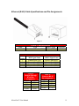
Ethernet (RJ45) Cable Specifications and Pin Assignments
Figure 3
Cable
10BASE-T
Table 8 - Cable Specification
Type
Max. Length
Cat. 3, 4, 5 100-ohm UTP
100 m (328 ft)
Connector
RJ45
Table 9 - J1 Ethernet
Pin
MDI Signal Name
Number
1
Transmit Data (TD+)
2
Transmit Data (TD-)
3
Receive Data (RD+)
6
Receive Data (RD-)
Pins 4, 5, 7, and 8 are not connected.
Table 10
Straight-Through
RJ-45 Pin
Assignments
End 1
End 2
1 (TD+)
1 (TD+)
2 (TD-)
2 (TD-)
3 (RD+)
3 (RD+)
6 (RD-)
6 (RD-)
MicroGate™ User Manual
MDI-X Signal Name
Receive Data (RD+)
Receive Data (RD-)
Transmit Data (TD+)
Transmit Data (TD-)
Table 11
Crossover RJ-45
Pin Assignments
End 1
End 2
1 (TD+) 3 (RD+)
2 (TD-)
6 (RD-)
3 (RD+) 1 (TD+)
6 (RD-)
2 (TD-)
11
IV. Installation and Configuration
System Requirements
You must meet the following requirements to install and configure the MicroGate™:
• Static IP address, Subnet Mask, and Gateway Address to assign the
MicroGate™
• A computer equipped with a 10 Mbps, 100 Mbps, or 10/100 Mbps Fast
Ethernet Card, or USB-to-Ethernet converter. Computer must have TCP/IP
protocols installed and have a fixed (static) or dynamic IP Address assigned to
it.
• MicroGate Discovery Utility CD (might be bundled with Raptor Web
Software™ CD)
• Network Cable connecting MicroGate™ directly to the computer (use a
Crossover type cable, see Table 11), or network cable connecting to the same
hub/switch that the computer is connected to (use Straight-Through type
cable, see Table 10).
• +5VDC Power Supply with mating connector
• Serial cable connecting your device(s) to one of the serial ports (see Table 5,
Table 6, and Table 7)
Connect the System
The MicroGate™ can be placed at any convenient location in the kitchen or office.
No special cooling requirements are needed, but you should keep the MicroGate™
away from any heating device, dusty or wet environments. If the MicroGate™ needs
to operate in a dusty or wet environment, it should be placed in a NEMA box. Make
sure to disconnect the power, remove the power cord from the outlet, and keep your
hands dry when handling the MicroGate™.
Basic Installation Procedure
1. Connect an Ethernet Cable from the MicroGate™ to one of the following:
a. Ethernet Port on computer using a Crossover type cable (see Table 11)
b. Ethernet Port on hub, switch, or router using a Straight-Through type
cable (see Table 10)
2. Connect a serial cable from your device(s) to one of the serial ports on the
MicroGate (see Table 5, Table 6, and Table 7 for pin assignments)
3. Connect the power cable to the MicroGate (see Table 3 or Table 4)
4. Plug the other side of the power cable to a +5VDC source, or to a wall outlet
if you are using a cable with power supply
5. Verify that DS1(Link) and DS4(Power) LEDs are on (see Table 2)
6. After approximately 30 seconds, verify that DS3 (Heartbeat) LED is flashing
MicroGate™ User Manual
12
Basic Network Configuration Procedure
1. Start the Discovery Utility by selecting Start > Programs > Raptor Web
Software > ECSDiscovery – This utility might reside in a different location
depending on how it was installed.
Figure 4
2. Click on Start Discovery (see Figure 4, note #1) to start looking for E-Control
Systems’ units on your network. Note: This could take up to 30 seconds to
complete
Figure 5
3. A list of all of the ECS units on the network is listed sorted by their MAC
Address (see Figure 5, note #4). Find the MAC address of the MicroGate™
that you want to configure (the MAC address is shown on a white label on the
underside of the MicroGate™). Highlight the row in the table that corresponds
to the correct MAC Address/Unit you want to re-configure.
MicroGate™ User Manual
13
Figure 6
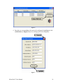
4. Once the row corresponding to the unit to be configured is highlighted, click
on Edit Unit (see Figure 6, note #1) to bring up the Unit’s Properties
Figure 7
MicroGate™ User Manual
14
5. Change the IP Address, Subnet Mask, and Gateway Address as needed and
then click on Update (see Figure 7, note #1) to send configuration to the unit.
To quit without updating the unit, click on the X (see Figure 7, note #2)
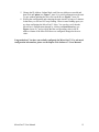
6. Writing the configuration and restarting the unit can take as long as 2 minutes.
In that time you will see DS3 stop flashing. When it starts flashing again you
are done configuring the MicroGate™. Note: You can also verify that the
MicroGate’s configuration changed by clicking on Start Discovery (see
Figure 4, note #1), and verifying that the corresponding value in the IP
address column of the MicroGate that was configured changed to the new
value.
Congratulations! You have successfully configured the MicroGate™. For advanced
configuration information, please see the Raptor Web Software™ Users Manual.
MicroGate™ User Manual
15
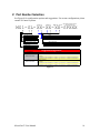
V. Part Number Selection
See Figure 8 for configuration options and suggestions. For custom configurations please
consult E-Control Systems.
RS232 #1
RS232 #2
RS485 #1 and #2
Optional Special Build
(Consult Factory)
MG1- SL- XX- XX- XX-SPXXX
Functional Options
L No add-on modules
M 33.6 Kbps Modem Module
S Standard (no options)
B Battery backup
C SRAM and battery backup
Packaging Options
1 Open Frame
2 Boxed (enclosure)
Connector Options
A
None
B
Header only
C
Shrd/Keyed Connector for wire or ribbon type mating cables*
R
S
T
Right Angle Mount
Vertical Mount
Not applicable
Suggested Configurations
Part Number
MG1-SL-CS-CS-CS
MG1-CL-CS-CS-CS
Description
No add-on modules
No Options
Open Frame
Shrouded/Keyed Vertical Mount Wire or Ribbon Type Connector* for RS232 #1 and RS232 #2
Shrouded/Keyed Vertical Mount Wire or Ribbon Type Connector* for RS485 #1 and RS485 #2
No add-on modules
SRAM and battery backup
Open Frame
Shrouded/Keyed Vertical Mount Wire or Ribbon Type Connector* for RS232 #1 and RS232 #2
Shrouded/Keyed Vertical Mount Wire or Ribbon Type Connector* for RS485 #1 and RS485 #2
Figure 8
MicroGate™ User Manual
16
VI. Limited Warranties
E-Control Systems' Limited Warranty Statement
Limited Warranty Statement: E-Control Systems ("ECS") warrants its products to be free from
defects in workmanship and materials, under normal use and service, for the applicable warranty
term. All ECS products carry a standard 1 year limited warranty from the date of purchase from
ECS or its Authorized Reseller/Distributors. ECS may, at its own discretion, repair or replace any
product not operating as warranted with a similar or functionally equivalent product, during the
applicable warranty term. ECS will endeavor to repair or replace any product returned under
warranty within 30 days of receipt of the product. As new technologies emerge, older
technologies become obsolete and ECS will, at its discretion, replace an older product in its
product line with one that incorporates these newer technologies
All products that are replaced become the property of ECS. Replacement products may be either
new or reconditioned. Any replaced or repaired product carries, either a 30-day limited warranty
or the remainder of the initial warranty, whichever is longer. ECS is not responsible for any
custom software or firmware, configuration information, or memory data of Customer contained
in, stored on, or integrated with any products returned to ECS pursuant to any warranty. Products
returned to ECS should have any customer-installed accessory or add-on components, such as
expansion modules, removed prior to returning the product for replacement. ECS is not
responsible for these items if they are returned with the product. Customers must contact ECS for
a Return Material Authorization number prior to returning any product to ECS. Proof of purchase
may be required. Any product returned to ECS without a valid Return Material Authorization
(RMA) number clearly marked on the outside of the package will be returned to customer at
customer’s expense. Customers are responsible for all shipping charges from their facility to
ECS. ECS is responsible for return shipping charges from ECS to customer.
WARRANTIES EXCLUSIVE: IF A ECS PRODUCT DOES NOT OPERATE AS
WARRANTED ABOVE, CUSTOMER'S SOLE REMEDY SHALL BE REPAIR OR
REPLACEMENT OF THE PRODUCT IN QUESTION, AT ECS’ OPTION. THE FOREGOING
WARRANTIES AND REMEDIES ARE EXCLUSIVE AND ARE IN LIEU OF ALL OTHER
WARRANTIES OR CONDITIONS, EXPRESSED OR IMPLIED, EITHER IN FACT OR BY
OPERATION OF LAW, STATUTORY OR OTHERWISE, INCLUDING WARRANTIES OR
CONDITIONS OF MERCHANTABILITY AND FITNESS FOR A PARTICULAR PURPOSE.
ECS NEITHER ASSUMES NOR AUTHORIZES ANY OTHER PERSON TO ASSUME FOR
IT ANY OTHER LIABILITY IN CONNECTION WITH THE SALE, INSTALLATION,
MAINTENANCE OR USE OF ITS PRODUCTS. ECS SHALL NOT BE LIABLE UNDER
THIS WARRANTY IF ITS TESTING AND EXAMINATION DISCLOSE THE ALLEGED
DEFECT IN THE PRODUCT DOES NOT EXIST OR WAS CAUSED BY CUSTOMER'S OR
ANY THIRD PERSON'S MISUSE, NEGLECT, IMPROPER INSTALLATION OR TESTING,
UNAUTHORIZED ATTEMPTS TO REPAIR, OR ANY OTHER CAUSE BEYOND THE
RANGE OF THE INTENDED USE, OR BY ACCIDENT, FIRE, LIGHTNING, OR OTHER
HAZARD. LIMITATION OF LIABILITY: IN NO EVENT, WHETHER BASED IN
CONTRACT OR TORT (INCLUDING NEGLIGENCE), SHALL ECS BE LIABLE FOR
INCIDENTAL, CONSEQUENTIAL, INDIRECT, SPECIAL, OR PUNITIVE DAMAGES OF
ANY KIND, OR FOR LOSS OF REVENUE, LOSS OF BUSINESS, OR OTHER FINANCIAL
LOSS ARISING OUT OF OR IN CONNECTION WITH THE SALE, INSTALLATION,
MAINTENANCE, USE, PERFORMANCE, FAILURE, OR INTERRUPTION OF ITS
PRODUCTS, EVEN IF ECS OR ITS AUTHORIZED RESELLER/DISTRIBUTOR HAS BEEN
MicroGate™ User Manual
17
ADVISED OF THE POSSIBILITY OF SUCH DAMAGES. SOME COUNTRIES DO NOT
ALLOW THE EXCLUSION OF IMPLIED WARRANTIES OR THE LIMITATION OF
INCIDENTAL OR CONSEQUENTIAL DAMAGES FOR CONSUMER PRODUCTS, SO THE
ABOVE LIMITATIONS AND EXCLUSIONS MAY NOT APPLY TO YOU. THIS
WARRANTY GIVES YOU SPECIFIC LEGAL RIGHTS, WHICH MAY VARY FROM
COUNTRY TO COUNTRY. NOTHING IN THIS WARRANTY SHALL BE TAKEN TO
AFFECT YOUR STATUTORY RIGHTS.
Firmware and Drivers
For latest driver, technical information and bug-fixes please visit www.eControlSystems.com or
call (818) 885-5228.
Statement of Conditions
In line with our continued efforts to improve internal design, operational function, and/or
reliability, ECS reserves the right to make changes to the product(s) described in this document
without notice. ECS does not assume any liability that may occur due to the use or application of
the product(s) described herein. In order to obtain the most accurate knowledge of installation,
bug-fixes and other product related information we advise to visit the relevant product support
page at www.eControlSystems.com before you start installing the equipment. All information is
subject to change without notice.
Limitation of Liability
In no event, whether based in contract or tort (including negligence), shall ECS be liable for
incidental, consequential, indirect, special or punitive damages of any kind, or for loss of revenue,
loss of business or other financial loss arising out of or in connection with the sale, installation,
maintenance, use, performance, failure or interruption of its products, even if ECS or its
authorized reseller/distributor has been advised of the possibility of such damages.
Copyright
Information furnished by E-Control Systems, Inc. (ECS) is believed to be accurate and reliable.
However, no responsibility is assumed by ECS for its use, nor for any infringements of patents or
other rights of third parties which may result from its use. No license is granted by implication or
otherwise under any patent or patent rights of ECS. ECS reserves the right to change
specifications at any time without notice.
Trademarks
MicroGate, Raptor Web Software, and Online Kitchen are trademarks of E-Control Systems, Inc.
Other product and company names are trademarks or registered trademarks of their respective
holders.
MicroGate™ User Manual
18