1
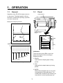
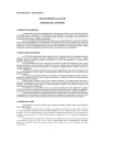
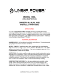
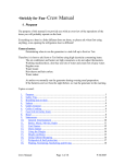
PRINTER PP-505 (For FE-700) SAFETY INSTRUCTIONS Safety Information for Operator Safety Information for Installer WARNING WARNING ELECTRICAL SHOCK HAZARD Do not open the cover of the equipment. Only qualified personnel should work inside the equipment. This equipment uses high voltage electricity which can shock or burn. Only qualified personnel should work inside the equipment. This equipment uses high voltage electricity which can shock or burn. Turn off the power at the ship's mains switchboard before beginning the installation. Post a warning sign near the switchboard to ensure that the power will not be applied while the equipment is being installed. Do not disassemble or modify the equipment. Fire, electrical shock or serious injury can result. Immediately turn off the power at the ship's mains switchboard if water or foreign object falls into the equipment or the equipment is emitting smoke or fire. Serious injury can result if the power is not turned off, or is applied while the equipment is being installed. CAUTION Continued use of the equipment can cause fire, electrical shock or serious injury. Observe the following compass safe distances to prevent interference to a magnetic compass: CAUTION Do not place liquid-filled containers on the top of the equipment. Fire or electrical shock can result if a liquid spills into the equipment. PP-505 Do not place heater near the equipment. Heat can melt the power cord, which can result in fire or electrical shock. Do not operate the unit with wet hands. Electrical shock can result. Use the correct fuse. Use of the wrong fuse can cause fire or damage the equipment. i standard compass steering compass 1.1 m 0.8 m WARNING LABEL A warning label is attached to the printer. Do not remove the label. If the label is missing or damaged, contact your dealer about replacement. WARNING To avoid electrical shock, do not remove cover. No user-serviceable parts inside. Name: Warning Label (1) Type: 86-003-1011 Code No.: 100-236-231 ii FOREWORD A Word to the Owner of the PP-505 Congratulations on your choice of the FURUNO PP-505 Printer. For over 50 years FURUNO Electric Company has enjoyed an enviable reputation for innovative and dependable marine electronics equipment. This dedication to excellence is furthered by our extensive global network of agents and dealers. Your printer is designed and constructed to meet the rigorous demands of the marine environment. However, no machine can perform its intended function unless installed, operated and maintained properly. Please carefully read and follow the recommended procedures for installation, operation and maintenance. We would appreciate hearing from you, the end-user, about whether we are achieving our purposes. Thank you for considering and purchasing FURUNO equipment. The PP-505 prints a depth graph or a log consisting of date, time, depth, draft, latitude, longitude and heading. You can choose which to print with the [MODE] key. The main features are • Automatic operation; just turn on the power and the printer readies itself for printing. • Selectable printing interval. • LEDs show equipment status. iii TABLE OF CONTENTS 1. OPERATION.................................................................................................. 1 1.1 1.2 1.3 General..............................................................................................................................1 Panel .................................................................................................................................1 Turning on the Power.........................................................................................................2 2. REPLACEMENT OF THERMAL PAPER .................................................... 3 3. INSTALLATION ........................................................................................... 4 3.1 3.2 3.3 3.4 3.5 Complete Set .....................................................................................................................4 General Mounting Considerations......................................................................................4 Tabletop/Bulkhead Mount .................................................................................................5 Flush Mount .....................................................................................................................5 Wiring ................................................................................................................................6 4. MAINTENANCE .......................................................................................... 7 APPENDIX REPLACEMENT OF PRINTER ASSEMBLY/THERMAL HEAD AP-1 SPECIFICATIONS........................................................................................... SP-1 PACKING LIST OUTLINE DRAWING INTERCONNECTION DIAGRAM iv 1. OPERATION 1.1 General 1.2 Operation of the PP-505 is simple; just turn on the power. The depth graph or the log, whichever is selected for printing, is printed out at the interval set. Panel Power Switch PRINTER PP-505 GRAPH LOG PAPER Below are example printouts. MODE INTERVAL POWER ON RANGE FEED/MARK Thermal Paper Cover 2003/12/01 13:05:00 038.6m/01.0m 35 20.02’N/135 45.15’E 15.1kt 008.0deg M GRAPH LOG PAPER 13:05:00 20m Marker 40m 60m 80m 100m LED MODE INTERVAL Depth graph RANGE 2003/12/01 13:05:00 038.6m/01.0m 35 20.02’N/135 45.15’E 15.1kt 008.0deg Key FEED/MARK 2003/12/01 13:05:00 038.6m/01.0m 35 20.02’N/135 45.15’E 15.1kt 008.0deg 2003/12/01 13:05:00 038.6m/01.0m 35 20.02’N/135 45.15’E 15.1kt 008.0deg 2003/12/01 13:05:00 038.6m/01.0m 35 20.02’N/135 45.15’E 15.1kt 008.0deg Indicators M 2003/12/01 13:05:00 038.6m/01.0m 35 20.02’N/135 45.15’E 15.1kt 008.0deg Date There are three (red) LEDs on the front panel which light or blink according to equipment status. Heading Speed Longitude Latitude Depth, Time Draft ! GRAPH Lights while the depth graph is being printed. Depth data log " LOG Lights while the depth data log is being printed. # PAPER Blinks when the paper has run out, and is accompanied by the audible alarm. The audible alarm sounds for five seconds; you may silence it sooner by hitting any key. 1 OPERATION Changing the mode Feeding the paper/Printing the marker Press the [MODE] key to change the printing mode from depth graph to log printing alternately. To feed the paper, press and hold down the [FEED/MARK] key. Press the [FEED/MARK] key momentarily to print the marker. The printing interval setting is printed whenever the [MODE] key is pressed. 1.3 Changing the printing interval Turning on the Power Flip down the thermal paper cover and turn on the [POWER] switch. The PP-505 then carries out the diagnostic test. After the test has been completed, the printer is ready to print depth data. Press the [INTERVAL] key to choose printing interval. Depth graph: 9 s → 45 s → 90 s → 450 s Log: 10 s → 30 s → 1 m → 10 m Note: “Disconnect” is printed if data from the navigation echo sounder is not being received during printing or the navigation echo sounder is displaying the system menu. The latest data of the printing interval is printed. When the printing interval is changed, the printing interval setting is printed and marked with an asterisk. To turn off the power, press the [POWER] switch. Note: You can skip over setting(s) by pressing the key consecutively within one second. Changing the depth range Press the [RANGE] key to change the depth range. When the depth range is changed, the depth is printed and marked with an asterisk. Range: 5 m → 10 m → 20 m → 40 m → 100 m → 200 m → 400 m→ 800 m Note1: Depth range automatically changes depending on the depth range on the navigational echo sounder. Note2: You can skip over setting(s) by pressing the key consecutively within one second. 2 2. REPLACEMENT OF THERMAL PAPER When the thermal paper runs out, the PAPER LED blinks, printing stops automatically and the audible alarm sounds for five seconds. With 1 m of paper remaining, a red paper end mark appears on the paper. When the red mark appears, replace the thermal paper as shown in the procedure below. Adhesive may remain on the paper after tape is removed. This may cause a paper jam, so cut paper to remove adhesive. Tape Adhesive REQUIRED THERMAL PAPER Type: TP0340 (112 mm × 40 m) Code No.: 000-801-765 (One roll supplied.) 4. Insert the paper into the paper insertion slot just above the paper container and press the [FEED/MARK] key to feed out the paper. 5. Set the paper in the paper container. 1. Press the [FEED/MARK] key to draw out the remaining thermal paper. 2. Pull the thermal paper cover forward and take out the paper spool. 3. Curve the leading edge of the new roll paper to ensure smooth feeding, and set the paper spool to the new roll paper. Confirm that paper is fed out through the slot. Insertion slot 6. Press the [FEED/MARK] key to confirm that the paper is properly aligned. If the paper comes out with its edges wrinkled, continue to press the [FEED/MARK] key. Correct alignment will be made automatically. 7. Close the thermal paper cover. 8. Press the [MODE] key to complete the replacement of thermal paper. (The PAPER LED goes off.) Note: If the PP-505 receives data when there is no paper it doesn’t print them out after replacing the thermal paper. Red mark Reel Thermal paper cover Remedy for paper jam If the paper is jammed cut it off at the front panel and rewind it into the paper container. 3 3. INSTALLATION 3.1 Complete Set Name Type Mass Qty 3.1 kg (with hanger) 1 Main Unit PP-505 Spare Parts SP08-01600 1 Installation Materials CP16-00800 1 Accessories FP08-00500 1 Flush Mount Kit OP08-4 1 3.2 Remark Option (004-511-330) Heat accumulation General Mounting Considerations The PP-505 consumes very little power, so there is no need for forced air ventilation. However, it is recommended to provide at least some space around the unit to allow for circulation of cooling air. This equipment can perform its intended functions only if it is installed properly. Keep in mind the following when selecting a mounting location. The unit should be kept out of direct sunlight because of heat that can build up inside the cabinet. Excessive heat can darken the thermal paper. Water spray The PP-505 is designed and constructed to be able to withstand the humidity and corrosive atmosphere common to the pilothouse, but it is not designed to be used outside, directly exposed to the environment. Salt water spray will most assuredly cause damage to the sensitive components inside. Onboard noise To avoid mutual interference with other power equipment, do not install this unit near a power cable or equipment having a motor. Mechanical shock and vibration Compass safe distance The PP-505 is constructed to withstand minor shocks and engine vibration, but excessive and continued shock can shorten the life of the precision printer mechanism. Shock may also degrade the print quality due to uneven contact between the printer head and the thermal paper. A magnetic compass will be affected if the printer is placed too close to the compass. Observe the following compass safe distances to prevent deviation to the compass. Standard: 1.1 m Steering: 0.8 m 4 3. INSTALLATION 3.3 Tabletop/Bulkhead Mount 3.4 Flush mount panel kit is optionally supplied. The main unit can be mounted on a desktop, bulkhead, or in a panel. Make sure the selected location is strong enough to support the main unit against possible vibration and shock. If necessary, appropriate reinforcement measures should be made on the mounting area. Flush mount kit OP08-4 (Code No.: 004-511-330) Name Flush mount panel Tapping screw Nylon washer Pan head screw Hex. bolt Flat washer Flat washer Spring washer Rosette washer Flush mount angle Liner Tabletop mount 1. Drill four pilot holes for the hanger. 2. Fix the hanger with the tapping screws (5×20) supplied. 3. Place the unit in the hanger and tighten knobs. 268 2.9 kg 107 141 Tapping screw Hanger Knob bolt Flat washer Hanger washer 0.2 kg 90 60 120 Flush Mount 200 480 Bulkhead mount When the unit is installed on the bulkhead, fix the hanger as shown below. 5 Type Code No. 22-008-0125 100-103-351 Qty 1 5X20 000-800-488 4 2.8X7X0.5 000-800-728 4 M3X8 000-861-495 4 M8X16 M5 000-862-145 000-864-128 2 4 M8 000-864-130 2 M8 000-864-262 2 M3 000-864-900 4 22-008-0126 100-103-361 2 22-008-0127 100-103-371 2 3. INSTALLATION 3.5 1. Referring to the illustration below, prepare a cutout in the mounting area and drill four pilot holes for the flush mount angles. Refer to the interconnection diagram at end of manual for connection. Refer to the outline drawing at end of manual. 2. Fix the liner and the flush mount angles to the main unit. 3. Connect the cables at the rear of main unit. 4. Fix the main unit to the panel cutout with four tapping screws. 5. Fix the flush mount panel to the flush mount angles with the screws and washers supplied. 295 280 116 156 7 10 Flat washer Spring washer Hex. bolt Flat washer Tapping screws Liner Wiring Flush mount angle Flush mount panel Rosette washer Pan head screw Nylon washer 6 4. MAINTENANCE Checking the power connector Fuse Replacement Check for loosened or disconnected power connector. To protect the equipment from serious damage, a 3A fuse is provided on the rear cabinet of the main unit. The fuse protects against overvoltage/reverse polarity of the ship’s mains or internal fault of the equipment. If the fuse has blown, first find out the cause of the trouble before replacing it. A fuse rated for more than 3 A should not be used, since it may permanently damage the equipment. Damage due to overfusing is not covered by the warranty. WARNING Do not open the cover of the equipment. This equipment uses high voltage electricity which can shock or burn. Only qualified personnel should work inside the equipment. CAUTION Do not disassemble or modify the equipment. Use the correct fuse. Fire, electrical shock or serious injury can result. Use of the wrong fuse can cause fire or damage the equipment. Diagnostic test When turning on the power, if any fault is detected, the appropriate LED lights. GRAPH: ROM error LOG: RAM1 error PAPER: RAM2 error If any LEDs light, contact your dealer. Cleaning Accumulated dust should be regularly removed from both exterior surfaces and the interior. The only recommended cleaning material for exterior surfaces is a soft cloth. For the interior, use a handheld vacuum. BE SURE TO TURN OFF THE POWER BEFORE CLEANING THE INSIDE OF THE UNIT. Do not use chemical-based cleaners to clean the display unit-they can remove paint and markings. 7 APPENDIX REPLACEMENT OF PRINTER ASSEMBLY/TERMAL HEAD 1. Loosen the four M4 × 15 screws fixing the rear cabinet to the main unit assembly. 2. Disconnect the connectors connected to the rear cabinet to detach the rear cabinet. 4. Move the carriage to position A by rotating the carriage shaft by fingers, as shown below, where the thermal head assembly can be replaced easily. Carriage Shaft Carriage Rear Cabinet P1 NH 4P A P5 NH 6P M4 × 15 screw (4 pcs.) Main Unit Assembly 3. Separate the panel assembly from the main unit assembly by removing the recording paper from the paper container. 5. Remove the flexible cable support from the carriage by lifting it toward direction B as in the figure below. Printer Assembly Main Unit Assembly PANEL CPU Board P4 PH 12P P8 PH 10P P10 PH12P M4 × 8 screw (4 pcs.) Do not Disconnect. Panel Assembly AP-1 Flexible Cable Support Carriage 6. Pull out the connector end of the flexible cable from the connector. Take care not to damage the flexible cable. End of Flexible Cable (Connector) 9. Hold the flexible cable end with a tweezers and pull it out until it is positioned as shown below. 180° Head Holder 90° Thermal Head 7. Remove the thermal head from the head holder with a screwdriver as shown below, and then take the thermal head assembly out of the printer assembly. Thermal Head 10. Turn the head by 90° so that it is parallel with the head holder as shown below. While pulling the head holder toward you, insert the head into the head holder. Head Holder Screwdriver Head Head Holder Carriage Projection Hole Flexible Cable 8. As shown below, pass the flexible cable (connector side) of a new thermal head assembly beneath the guide pins. End of Flexible Cable Guide Pin AP-2 11. Fix the flexible cable to the carriage with the flexible cable support, inserting the projection on the carriage into the hole of the cable. 12. Fold back the end of the cable and insert it into the connector. 180° End of Flexible Cable Flexible Cable Support Carriage Projection AP-3 FURUNO SPECIFICATIONS OF PRINTER PP-505 1 DATA FORMAT 1.1 Receiving System RS-232C 1.2 Speed 9600 bps 1.3 Data Length 8 bits 1.4 Parity Non 1.5 Stop Bit 1 bit 2 PRINTER SECTION 2.1 Printing System 9 dots serial thermal head printing system 2.2 Character Alphanumeric 2.3 Dot Pitch 0.28 mm/ dot 2.4 Number of Dot in Line 300 dots 2.5 Number of Characters Max. 80 characters/ line 2.6 Print Speed 31 characters/second 2.7 Roll Paper TP-0340, 112 mm (W) x 40 m (L) 3 RATED VOLTAGE/CURRENT 12-32 VDC, 0.72-0.28 A 4 ENVIRONMENTAL CONDITION 4.1 Ambient Temperature -15°C to +55°C 4.2 Relative Humidity 95% at 40°C 4.3 Waterproofing IPX0 4.4 Vibration IEC 60945 5 COATING COLOR Chassis: 2.5GY5/1.5, Panel: N3.0 SP - 1 E5540S03-1 Takahashi T. Takahashi T. Takahashi T. Takahashi T. C B A 08S0157 *3 FM14-2P NOTE 1. LOCAL SUPPLY. 2. MAX 15m. 3. FITTED AT FACTORY. 4. GROUNDING WITH CONNECTOR HOUSING. 注記 1) 現地手配。 2)最大15m。 3)工場にて取付済み。 4) コネクタケースでアース。 船内電源 SHIP'S MAINS 12-32 VDC 1 1 2 PP-505 PRINTER プリンタ 2 08S0087 RXD (H) 1 TXD (H) 2 0V 3 TXD (C) 4 RXD (C) 5 +12V 6 N.C. 7 *4 P C2366-C03-A Takahashi T. APPROVED DWG.No. *2 H. Maki Takahashi T. P 16-006-3022-0 FE-700 CO-SPEVV-SD-C0.2x2P, φ13.5 *1 CHECKED July, 23 2003 DRAWN FM14-7P 3 4 5 6 FE-702 NAME 名 称 TITLE PRINTER INTERCONNECTION DIAGRAM 相互結線図 PP-505 プリンタ EIA232-TD EIA232-RD GND TB1 DISTRIBUTION BOX 分配箱 4