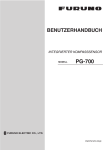
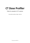
1
OPERATOR'S MANUAL
INTERFACE UNIT
MODEL
IF-NMEASC
www.furuno.co.jp
IMPORTANT NOTICES
• This manual is intended for use by readers with a solid knowledge of English.
• No part of this manual may be copied or reproduced without written permission.
• If this manual is lost or worn, contact your dealer about replacement.
• The contents of this manual and equipment specifications are subject to change without notice.
• Store this manual in a convenient place for future reference.
• FURUNO will assume no responsibility for the damage caused by improper use or modification
of the equipment (including software) by an unauthorized agent or a third party.
• When it is time to discard this product it must be done according to local regulations for disposal
of industrial waste. For disposal in the USA, refer to the Electronics Industries Alliance (http://
www.eiae.org/).
i
SAFETY INSTRUCTIONS
The operator and installer must read the applicable safety instructions before attempting to
install or operate the equipment.
WARNING
Indicates a potentially hazardous situation which, if not avoided,
could result in death or serious injury.
CAUTION
Indicates a potentially hazardous situation which, if not avoided,
can result in minor or moderate injury.
Warning, Caution
Prohibitive Action
Mandatory Action
Safety instructions for the operator
WARNING
WARNING
Do not open the equipment.
Do not place liquid-filled containers on
the top of the equipment.
Only qualified personnel should work
inside the equipment.
Fire or electrical shock can result if a
liquid spills into the equipment.
Do not disassemble or modify the
equipment.
Make sure no rain or water splash
leaks into the equipment.
Fire, electrical shock or serious injury can
result.
Fire or electrical shock can result if water
leaks into the equipment.
Immediately turn off the power at the
power source if
- water leaks into the equipment
- something is dropped into the
equipment
- the equipment is emitting smoke or
is on fire
- the equipment is emitting strange
noises
WARNING
Continued use of the equipment can
cause fire or electrical shock. Contact a
FURUNO dealer or agent for service.
Do not operate the equipment with wet
hands.
Electrical shock can result.
Use the proper fuse.
Use of the wrong fuse can cause fire
or electrical shock.
ii
SAFETY INSTRUCTIONS
Safety instructions for the installer
CAUTION
WARNING
Observe the following compass safe
distances to prevent interference to a
magnetic compass:
Turn off the power at the switchboard
before beginning the installation.
Fire or electrical shock can result if the
power is left on.
Standard
compass
Do not install the equipment where it
may get wet from rain or water splash.
IF-NMEASC
1.05 m
Steering
compass
0.70 m
Water in the equipment can result in fire,
electrical shock or damage to the equipment.
Be sure that the power supply is
compatible with the voltage rating of the
equipment.
Warning labels are attached to the equipment.
Do not remove these labels. If a label is missing
or illegible, contact a FURUNO agent or dealer
.
about replacement.
Connecting an incompatible power supply
can cause fire or damage the equipment.
The voltage rating appears on the inlet
of power.
WARNING
Name: Warning Label (1)
To avoid electrical shock, Type: 86-003-1011-1
do not remove cover. No
user-serviceable parts Code No.: 100-236-231
Do not connect this unit to
NMEA 2000 bus.
It is intended for one-to-one connection
with the SC-30. Connection to an
NMEA 2000 bus can result in network
trouble and, in the worst case, fire.
WARNING
To avoid electrical shock,
do not remove cover.
No user-serviceable parts
inside.
Do not open the equipment.
Only qualified personnel should work
inside the equipment.
iii
Name: Warning Label (2)
Type: 86-129-1001-1
Code No.: 100-236-741
TABLE OF CONTENTS
FOREWORD ....................................................................................................................v
SYSTEM CONFIGURATION ..........................................................................................vi
1.
MOUNTING ...............................................................................................................1
1.1 Equipment List .............................................................................................................. 1
1.2 Mounting Procedure...................................................................................................... 1
2.
WIRING .....................................................................................................................2
3.
ADJUSTMENTS........................................................................................................4
3.1 LEDs and Equipment Status ......................................................................................... 4
3.2 Setting Up NMEA Ports................................................................................................. 5
3.3 Heading, Pitch and Roll Offsets .................................................................................... 8
4.
OPERATION .............................................................................................................9
5.
MAINTENANCE, TROUBLESHOOTING...............................................................10
5.1
5.2
5.3
5.4
5.5
Preventive Maintenance.............................................................................................. 10
Replacing the Fuse ..................................................................................................... 11
Troubleshooting .......................................................................................................... 11
Self Test ...................................................................................................................... 12
Memory Clear.............................................................................................................. 13
SPECIFICATIONS .....................................................................................................SP-1
OUTLINE DRAWING ................................................................................................... D-1
INTERCONNECTION DIAGRAM ................................................................................ S-1
iv
FOREWORD
A Word to the Owner of the IF-NMEASC
Congratulations on your choice of the FURUNO IF-NMEASC Interface Unit. We are confident you
will see why the FURUNO name has become synonymous with quality and reliability.
For 60 years FURUNO Electric Company has enjoyed an enviable reputation for quality marine
electronics equipment. This dedication to excellence is furthered by our extensive global network
of agents and dealers.
This equipment is designed and constructed to meet the rigorous demands of the marine environment. However, no machine can perform its intended function unless installed, operated and
maintained properly. Please carefully read and follow the recommended procedures for installation, operation and maintenance.
Thank you for considering and purchasing FURUNO equipment.
Features
The IF-NMEASC is a dedicated interface unit for the SC-30 Satellite Compass. It receives NMEA
2000®* format heading, pitch, roll and GPS position data from the SC-30, converts them to NMEA
0183 format data and outputs the converted data to external equipment.
• Input port: One NMEA 2000 format port
• Four output ports: NMEA 0183x2, AD-10x1, Analog (pitch and roll)x1
• Offsets for heading, pitch and roll
*: NMEA 2000 is a registered trademark of the National Marine Electronics Association USA.
v
SYSTEM CONFIGURATION
SC-30
NMEA 2000
IF-NMEASC
Radar
Current Indicator
Scanning Sonar
Other
NMEA 0183
AD-10
Roll, Pitch
Video Plotter
Radar
Autopilot
Current Indicator
Scanning Sonar
Video Sounder
ECDIS
AIS
Current Indicator
Scanning Sonar
Other
IF-NMEASC
INTERFACE UNIT
: Standard supply
: Local supply
12-24 VDC
vi
1.
MOUNTING
1.1
Equipment List
Name
Type
Code No.
Qty
Remarks
Interface Unit
IF-NMEASC
-
1
Installation
Materials
CP20-03001
001-023-400
1 set
• Cable ties (CN-150N, 12 pcs.)
• Self-tapping screws (φ3x10, 4 pcs.)
Spare Parts
SP20-01301
001-019-800
1 set
Fuse FGMB 125V 2A (3 pcs.)
1.2
Mounting Procedure
When choosing a mounting location for the unit, keep the following points in mind:
• Select a location where shock and vibration are minimal.
• Locate the unit away from places subject to rain or water splash.
• Keep the unit away from exhaust pipes and vents.
• Locate the unit out of direct sunlight because of heat that can build up inside its cabinet.
• The location should be well ventilated.
• Observe the maintenance space mentioned in the outline drawing at the back of this manual
and the compass safe distances in the safety instructions.
#20
• Fix the unit with four φ3x10 self-tapping screws (supplied).
FIXING HOLES
4
#100
43
2-φ4
FIXING HOLES
199
118±0.5
R5
207±0.5
# Minimum recommended
maintenance space
1
56
2.
WIRING
Open the IF unit with your hands, detach the shield cover and connect external equipment, referring to the illustration below and the interconnection diagram. Cables are mainly connected to the
unit with WAGO connectors. See the instructions below for how to attach wiring to the connectors.
The opener for the WAGO connectors is attached to the inside of the inner cover. Fix cables to
their respective cable posts with cable ties (supplied). Run a ground wire (IV-2.0sq., local supply)
between the ground terminal and ship's grounding bus. Supply power from breaker on mains
switchboard.
Ground terminal
Power cable
J8 (Analog)
J7 (SC-30 Sensor)
J5 (NMEA 0183)
J4 (NMEA 0183)
J3 (AD-10)
Cable
post
Recommended Cables
Power cable:
AWG 16-20, and diameter less than 10 mm
(JIS* cable DPYC-1.5 or equivalent)
All other cables: AWG 16-28, shield, twisted, and diameter less than 8 mm
(JIS* cable TTYCS-1, TTYCS-4 or equivalent)
* Japan Industry Standard cable
How to wire WAGO connector
How to fix cable to cable post
1. Insert opener.
2. Press opener.
3. Insert core.
4. Release opener.
Twist
Fix cable to cable post with
two cable ties (supplied).
Cable post
Opener
Wire
Cable tie
2
2. WIRING
Cable construction
Power cable
DPYC-1.5
or equivalent
6
Approx. 40
3
Sheath
Vinyl tape
Armor
Scrape off paint.
45
Sheath
φ = 11.7 mm
Armor
Conductor
S = 1.5 mm 2
φ = 1.56 mm
Lay this part on applicable cable
post and fix with two cable ties.
Approx. 120
Cable connected to SC-30
MJ-A10SPF0015-150C
Aluminum tape
7-core
6
Cover drain wire
with vinyl tubing.
Data cable
TTYCS-1
or equivalent
Approx. 70
Braided shield
Armor
Lay this part on applicable cable
post and fix with two cable ties.
3
Armor
Scrape off paint.
Vinyl tape
6
45
Sheath
Shield
φ = 10.1 mm
Lay this part on applicable cable
post and fix with two cable ties.
Solder vinyl wire to
braided shield.
Conductor
S = 0.75 mm 2
φ = 1.11 mm
Approx. 70
Data cable
TTYCS-4
or equivalent
Braided shield
φ = 16.3 mm
3
Vinyl sheath
Armor
Vinyl tape.
Armor
6
Sheath
Shield
Conductor
S = 0.75 mm2
φ = 1.11 mm
Solder vinyl wire to
braided shield.
Lay this part on applicable
cable post and fix with two
cable ties.
Approx. 90
Data transmission cable
supplied by FURUNO
6
Braided shield
Solder vinyl wire to
braided shield.
Lay this part on applicable cable
post and fix with two cable ties.
WARNING
Do not connect this unit to NMEA 2000 bus.
It is intended for one-to-one connection with the SC-30. Connection to
an NMEA 2000 bus can result in network trouble and, in the worst case, fire.
3
3.
ADJUSTMENTS
3.1
LEDs and Equipment Status
The six LEDs above the heading indication light, flash or go off according to equipment status.
GPS OUTPUT PROCESSING
Status LEDs
for SC-30
CR33: Status LED
for IF-NMEASC
SENSOR1
SENSOR2
Heading
Pitch
Sentence
Bps
Sentence
Bps
Menu/
Cancel
Roll
Output
Interval
Output
Interval
-
Enter
+
LED state and equipment status
LED
LED state and equipment status
GPS
ON: Both GPS antennas in the SC-30 are receiving from five or more satellites.
OFF: One of the GPS antennas is receiving from 3 or fewer satellites.
OUTPUT
ON: All data is output from the SC-30 normally.
Flashing: Motion (heading, roll, pitch) is output (heave is fixed at 0, position
and speed are normal) by dead reckoning.
OFF: Heading output is stopped.
PROCESSING
ON: GPS processor is functioning properly.
Flashing: Initializing for GPS.
OFF: Not enough satellites received.
SENSOR1
ON: Rate gyro normal on all three axes.
OFF: Rate gyro error.
SENSOR2
ON: Acceleration sensor normal on all three axes.
OFF: Acceleration sensor error.
CR33
Flashing: Valid NMEA 2000 data is input.
ON: No valid NMEA 2000 data is input.
OFF: CPU error, or no power.
4
3. ADJUSTMENTS
3.2
Setting Up NMEA Ports
Ports J4 and J5 output data in NMEA 0183 format. Select the data to output from those ports,
along with baud rate and output interval. The default settings are as shown in the table below.
Default settings for ports 2 and 3
Port no.
Sentence
Baud rate (bps)
Tx interval (ms)
J4 (Port 2)
HDT (Heading)
4800
100
J5 (Port 3)
ATT (Heading, pitch, roll)
HVE (Heave)
38400
25
1. Grasp the cover at its right and left sides, pull the cover outward slightly and then lift the cover
to remove it.
2. Open the inner cover and turn on the power.
On the circuit board, find the heading indication, several LEDs, and four operating buttons.
The Heading LED is lit.
OUTPUT PROCESSING
When offset
is minus
0
Heading
Offset
3
Pitch
Port 2 Sentence
Bps
Port 3 Sentence
Bps
Menu/
Cancel
Operating
buttons
Roll
Output
Interval
Output
Interval
-
Enter
Use the [Menu/Cancel]
button to show the
heading indication.
Push the [Enter] button
to show the heading
offset value.
+
3. Push the [Menu/Cancel] button several times to light the Sentence LED on the Port 2 line.
4. Push the [Enter] button. The Sentence LED starts flashing and the sentence currently selected to output from port 2 is shown with a numeric. See the illustration below for numeric and
data sentence.
Current sentence setting
(example: 1: HDT (Heading, true))
OUTPUT PROCESSING
Sentence
LED
Offset
Port 2
0
0 0 3
Heading
Pitch
Sentence
Bps
Port 3 Sentence
Bps
Menu/
Cancel
Other indications:
2: HDG (Heading, Variation, Deviation)
3: HDM (Heading, Magnetic)
4: ATT (Heading, pitch, roll) and HVE (Heave)
5: VTG (Course over ground and ground speed)
GGA (Global positioning system(GPS fix data)
ZDA (Date and time)
6: RMC (Recommended minimum specific
GPS/TRANSIT data)
ZDA (Date and time)
7: Sentences of 4 and 5.
8: Sentences of 6 and 1.
Enter
Roll
Output
Interval
Output
Interval
-
+
5. Push the [+] or [-] button to display the numeric corresponding to the data sentence you wish
to output.
6. Push the [Enter] button. The sentence LED stops flashing.
5
3. ADJUSTMENTS
7. Push the [Menu/Cancel] button to light the Bps LED on the Port 2 line.
Bps
LED
OUTPUT PROCESSING
0
0 0 3
Heading
Pitch
Port 2 Sentence
Bps
Port 3 Sentence
Bps
Offset
Menu/
Cancel
Roll
Output
Interval
Output
Interval
-
Enter
+
8. Push the [Enter] button. The Bps LED starts flashing and the current bps setting appears.
OUTPUT PROCESSING
0
0 0 3
Offset
Heading
Pitch
Port 2
Sentence
Bps
Port 3 Sentence
Bps
Menu/
Cancel
Other indications:
960: 9600 bps
1920: 19200 bps
3840: 38400 bps
Roll
Output
Interval
Output
Interval
-
Enter
Current bps setting
(example: 4800 bps)
+
9. Push the [+] or [-] button to select desired baud rate. The choices are 4800, 9600, 19200 and
38400 (bps).
10. Push the [Enter] button. The bps LED stops flashing.
11. Push the [Menu/Cancel] button to light the Output interval LED on the Port 2 line.
12. Push the [Enter] button. The Output Interval LED starts flashing and the current output interval
setting appears.
OUTPUT PROCESSING
Offset
Port 2
0
0 0
Heading
Pitch
Sentence
Bps
Port 3 Sentence
Bps
Menu/
Cancel
Enter
Current output interval setting (Port 2)
25:
25 ms
100: 100 ms
200: 200 ms
1000: 1000 ms
2000: 2000 ms
Roll
Output
Interval
Output
Interval
-
+
6
3. ADJUSTMENTS
13. Push the [+] or [-] button to select desired output interval, referring to the table below.
Sentence
number
Sentence
Output interval (ms)
4800 bps
9600 bps
19200 bps
25, 100, 200, 1000, 2000
38400 bps
1
HDT
100, 200,
1000, 2000
2
HDG
100, 200, 1000, 2000
3
HDM
100, 200,
1000, 2000
25, 100, 200, 1000, 2000
4
ATT, HVE
200, 1000,
2000
100, 200, 1000, 2000
25, 100, 200,
1000, 2000
5
VTG, GGA, ZDA
1000, 2000
6
RMC, ZDA
1000, 2000
7
ATT, HVE
200, 1000,
2000
100, 200, 1000, 2000
25, 100, 200,
1000, 2000
GGA, VTG, ZDA
1000(<1000), 2000
HDT
100, 200,
1000, 2000
RMC, ZDA
1000(<1000), 2000
8
25, 100, 200, 1000, 2000
1000(<1000), 2000
25, 100, 200, 1000, 2000
14. Push the [Enter] button. The output interval LED stops flashing.
15. Set up Port 3 similar to how you did Port 2.
16. Close the inner and outer covers.
7
3. ADJUSTMENTS
3.3
Heading, Pitch and Roll Offsets
Turn on the IF unit and wait approx. three minutes for the satellite compass to settle. Then, check
that heading, pitch and roll data are reasonable. If not, open the unit and enter appropriate offset(s).
1. Open the cover, referring to step 1 in the previous section for the procedure.
2. Open the inner cover.
On the circuit board, find the heading display, LED set, and operating buttons. The Heading
LED is lit
OUTPUT PROCESSING
When offset
is minus
Offset
0
Heading
3
Pitch
Port 2 Sentence
Bps
Port 3 Sentence
Bps
Operating
buttons
Menu/
Cancel
Enter
Use the [Menu/Cancel]
button to show the
heading indication.
Push the [Enter] button
to show the heading
offset value.
Roll
Output
Interval
Output
Interval
-
+
3. Push the [Menu/Cancel] button to light the applicable Offset LED (Heading, Pitch, or Roll) and
push the [Enter] button. The selected LED starts flashing and the display shows current offset
for item selected.
4. Use the [+] or [-] button to set offset. (You can push and hold down those buttons to speed up
the rate of incrementation.)
Range of offset
Heading: ±6°
Pitch, Roll: ±10°
5. Push the [Enter] button to finish. The display shows current heading, pitch or roll indication
with offset applied. The selected Offset LED stops flashing.
6. Close the inner and outer covers.
8
4.
OPERATION
Normally, no operation is required except to power the unit (from the switchboard). The ST-BY
LED on the cover is ON, OFF or flashing according to equipment state.
Flashing: NMEA 2000 data is input
ON: NMEA 2000 data is not input
OFF: Power loss, blown fuse, operation error
ST-BY LED
ST-BY
IF-NMEASC
9
INTERFACE UNIT
5.
MAINTENANCE, TROUBLESHOOTING
This chapter provides the information for keeping your unit in good working order.
NOTICE
WARNING
Do not apply paint, anti-corrosive
sealant or contact spray to coating
or plastic parts of the equipment.
ELECTRICAL SHOCK HAZARD
Do not open the equipment.
Only qualified personnel
should work inside the
equipment.
5.1
Those items contain organic solvents
that can damage coating and plastic
parts, especially plastic connectors.
Preventive Maintenance
Regular maintenance is important for good performance. Following the procedures in the table below will help maintain performance
Preventive maintenance
Item
Check point
Remedy
Cabling
Visually check cabling for
signs of wear and damage.
Replace damaged cables.
Ground
Check ground wire.
Check that ground wire is tightly fastened.
Check ground point for corrosion.
Cover
Cleanliness of cover.
Dust can be removed with a soft cloth. Do not use
chemical based cleaners to clean the cover, as they
can remove paint and markings and deform the cover.
10
5. MAINTENANCE, TROUBLESHOOTING
5.2
Replacing the Fuse
The 2A fuse inside the unit protects it from overcurrent and equipment fault. If the power cannot
be turned on, have a qualified technician check the fuse. If the fuse has blown, find out the cause
before replacing it. If it blows again, contact your dealer for advice.
Item
Type
Code No,
Fuse
FGMB 125V 2A PBF
000-157-479-10
5.3
Troubleshooting
This section provides simple troubleshooting procedures which the user can follow to restore normal operation. If normal operation cannot be restored, do not attempt to check inside the equipment. There are no user-serviceable parts inside.
Simple troubleshooting procedures
Symptom
Possible trouble
Remedy
• Power at switchboard is turned
off.
• Disconnected or damaged
power cable.
• Blown fuse.
• Check if power is on at switchboard.
• Signal cable between the SC30 and this equipment is damaged or disconnected.
• SC-30 is no received satellite
signal.
• Check if sensor cable is disconnected or damaged.
Data is not received
at external equipment
• Disconnected or damaged interconnection cable.
• Output settings may be incorrect.
• Check if cable is disconnected or
damaged.
• Have a qualified technician check the
settings.
Heading, pitch or roll
data is not correct
• Offsets entered in this equipment may be incorrect.
• Have a qualified technician check the
settings.
Power cannot be
turned on
Data is not received
from SC-30
11
• Check if power cable is disconnected
or damaged.
• Have a qualified technician check the
fuse.
• See the SC-30's operator's manual.
5. MAINTENANCE, TROUBLESHOOTING
5.4
Self Test
The self tests check the equipment for proper operation.
Self test 1
This test checks the two GPS receivers, output circuit, processor and two sensors for proper operation.
1. Remove the cover and shield cover from the equipment.
2. Press the [Menu/Cancel] button several times to show "- - -.1" on the display. The LED lamps
one by one in order, the Output Interval LED in the Port 3 line, and then the equipment goes
into the test mode.
GPS OUTPUT PROCESSING
IF-NMEASC status
SENSOR2
SENSOR1
Self test 1 activated
Heading
Pitch
Sentence
Bps
Port 3 Sentence
Bps
Menu/
Cancel
Enter
Roll
Output
Interval
Output
Interval
-
+
3. Press the [Enter] button, and the test proceeds as below.
• GPS receivers are checked. The GPS lamp lights if the receivers are normal.
• Communication between this equipment and the SC-30 is checked. The OUTPUT LED
lights if normal.
• The CPU memory access is checked. THe PROCESSING LED lights if normal.
• The rate gyro is checked. The SENSOR1 LED lights if normal.
• The acceleration sensor is checked. The SENSOR2 LED lights if normal.
When the test is finished, the nine LEDs below the display flash, and then the display shows
"End.1".
4. Press the [Enter] button to return to self test 1.
12
5. MAINTENANCE, TROUBLESHOOTING
Self test 2
This test checks this unit's processor and output for proper operation.
1. With the display showing " - - - .1", push the [Menu/Cancel] button. The display shows "- - - 2".
GPS OUTPUT PROCESSING
IF-NMEASC status
SENSOR2
SENSOR1
Self test 2 activated
Heading
Sentence
Bps
Sentence
Bps
Menu/
Cancel
Roll
Pitch
Output
Interval
Output
Interval
-
Enter
+
2. Press the [Enter] button to start the test.
If the results are normal all LEDs light. Then, the nine LEDs below the display flash and the
display shows "End.2".
3. Press the [Enter] button to return to the self test 2 display.
5.5
Memory Clear
The memory can be cleared to restore the default settings for the NMEA ports. Note that offsets
are not cleared.
1. Hold down the [Menu/Cancel] button together with the [+] button until the display shows "CLR". At this time all Status and Settings LEDs are on.
GPS OUTPUT PROCESSING
STATUS of IF-NMEASC
SENSOR2
SENSOR1
C L R
Heading
Pitch
Sentence
Bps
Sentence
Bps
Menu/
Cancel
Enter
Roll
Output
Interval
Output
Interval
-
+
2. Press the [Enter] button to clear the memory and restore all default settings. "END C" appears
upon completion.
3. After the memory is cleared, press the [Menu/Cancel] button to show the heading.
13
5. MAINTENANCE, TROUBLESHOOTING
This page is intentionally left blank.
14
FURUNO
IF-NMEASC
SPECIFICATIONS OF INTERFACE UNIT
IF-NMEASC
1
INPUT PORT
NMEA 2000*, for data I/O between FURUNO satellite compass SC-30
* NMEA 2000 is a registered trademark of the Nationa l Marine
Electronics Association.
2
OUTPUT PORT
NMEA 0183: Two ports (HDT, HDG, HMD, ATT*, HVE*, VTG, GGA,
RMC, ZDA)
* ATT (heading, pitch, roll) and HVE (heave) are FURUNO
proprietary sentences.
AD-10: One port
Analog: One port (pitch, roll)
3
NMEA 0183 OUTPUT INTERVAL
HDT, HDG, HDM, ATT, HVE: 25ms, 100 ms, 200 ms, 1 s, 2 s
VTG, GGA, RMC, ZDA: 1 s, 2 s
4
POWER SUPPLY
12-24 VDC: 1.0-0.6 A
5
ENVIRONMENTAL CONDITIONS
5.1 Ambient Temperature
-15°C to +55°C
5.2 Humidity
Less than 95% at 40°C
5.3 Waterproofing
IP20
5.4 Vibration
- From 2 Hz to 5 Hz to up to 13.2 Hz with an excursion of ±1 mm ±10%
-13.2 Hz to 100 Hz with a constant maximum acceleration of 7 m/s2
6
COATING COLOR
N2.5
SP - 1
E7265S02A-M
D-1
Jul.23'07 R.Esumi
C
B
A
TTYCS-1Q(*1) OR
CO-0.2x2P(*2)
TTYCS-1(*1) OR
CO-0.2x1P(*2)
*1
DPYC-1.5
NOTE
*1. SHIPYARD SUPPLY.
*2. OPTION.
注記
*1)造船所手配。
*2)オプション。
12-24VDC
ソナー他
SONAR, ETC.
CH-250/270
20P8195
1
2
3
4
5
6
7
8
*1
IV-2sq.
1
2
3
4
TB1
1 (+)
2 (-)
USB
J2
VBUS
DM 保守用
DP FOR MAINTENANCE
SG
1
2
3
4
TD1:DAT
TD2:SFT
J7
NET_S
NET_C
NET_H
NET_L
SG
RD
SD
FG
ANALOG
J8
ROLL
SG
PITCH
FG
1
2
3
4
5
AD-10
J3
TD1-A
TD1-B
TD2-A
TD2-B
FG
NMEA
J4
1 TD-A
2 TD-B
3 FG
NMEA
J5
1 TD-A
2 TD-B
3 FG
EQUIPMENT
OR
TERMINATOR
15/30m,φ10
アカ RED
クロ BLK
シロ WHT
アオ BLU
ムラサキ PPL
キ
YEL
ミドリ GRN
1
2
3
4
5
6
7
8
9
10
DWG.No.
SCALE
1
2
3
4
5
T.TAKENO
C7265-C01- C
MASS
kg
Jan.18'08 R.Esumi
1
2
3
4
5
REF.No.
4
20-030-5000-1
全長:40m以下
NAME
名 称
TITLE
INTERCONNECTION DIAGRAM
SATELLITE COMPASS
相互結線図
SC-30
サテライトコンパス
CABLE LENGTH: UP TO 40m MAX.
T-CONNECTOR
LTWSS050505
-FMF-TS001 *2
NET_FG
NET_S SC-30
NET_C
NET_H
NET_L
PWR_H
PWR_C
FG(SG)
SD
RD
EQUIPMENT OR TERMINATOR
XS2G-D5S7
MJ-A10SPF
MJ-A10SPF0017-150C/300C
1
6m,φ8
2
3
4
5
6
15/30m,φ7
7
(+)
アカ RED
1A
12-24VDC
8
(-)
クロ BLK
9
キ
YEL
保守用
10
ミドリ GRN
FOR MAINTENANCE
GND
*2
T-CONNECTOR
LTWSS050505
-FMF-TS001
LTW12-05AFFM
-SR7000
*2
FI-50-CHAIN
1/5/10/20m,φ6
LTW12-05AMMM
-SR7000
T.YAMASAKI
T-CONNECTOR
LTWSS050505
-FMF-TS001 *2
DRAWN
Jan. 16 '08
CHECKED
Jan. 16 '08
APPROVED
1
2
3
4
5
SC-30
NET_FG
NET_S
NET_C
NET_H
NET_L
PWR_H
PWR_C
FG(SG)
SD
RD
サテライトコンパス
SATELLITE COMPASS
SC-30
MJ-A10SPF0015-150C/300C, MJ-A10SPF
CO-0.2x1P: CO-SPEVV-SB-C 0.2x1P,φ8.5
CO-0.2x2P: CO-SPEVV-SB-C 0.2x2P,φ10.5
TTYCS-1Q(*1) OR
CO-0.2x2P(*2)
レーダー/潮流計
RADAR/CURRENT IND., ETC.
航法装置
NAV EQUIPMENT
(IEC61162-1)
航法装置
NAV EQUIPMENT
(IEC61162-1)
TTYCS-1(*1) OR
CO-0.2x1P(*2)
インターフェイスユニット
INTERFACE UNIT
IF-NMEASC *2
3
NET_FG
NET_S
NET_C
NET_H
NET_L
PWR_H
PWR_C
FG(SG)
SD
RD
XS2G-D5S7
MJ-A10SPF
MJ-A10SPF0016
1
1
-060C,6m,φ8
2
2
3
3
4
4
5
5
6
7
8
9
10
2
MULTI-FUNCTION DISPLAY
(POWER SUPPLY: 12-24VDC)
1
S-1
This page is intentionally left blank.
The paper used in this manual
is elemental chlorine free.
・FURUNO Authorized Distributor/Dealer
9-52 Ashihara-cho,
Nishinomiya, 662-8580, JAPAN
Telephone : +81-(0)798-65-2111
Fax
: +81-(0)798-65-4200
All rights reserved.
Printed in Japan
A : DEC . 2007
A1 : JAN . 28, 2008
Pub. No. OME-72651-A1
(DAMI )
IF-NMEASC
*00016689910*
*00016689910*
* 0 0 0 1 6 6 8 9 9 1 0 *