1
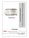
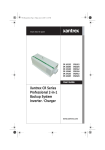
Flatbottom Series Electric Fryers
(Models 1824E, 2424E, and Combinations)
Installation & Operation Manual
Frymaster, a member of the Commercial Food Equipment Service Association, recommends
using CFESA Certified Technicians.
*8195700*
24-Hour Service Hotline 1-800-551-8633
Price: $6.00
819-5700
March 2003
Please read all sections of this manual and retain for future reference.
NOTICE
IF, DURING THE WARRANTY PERIOD, THE CUSTOMER USES A PART FOR THIS ENODIS
EQUIPMENT OTHER THAN AN UNMODIFIED NEW OR RECYCLED PART PURCHASED
DIRECTLY FROM FRYMASTER DEAN, OR ANY OF ITS AUTHORIZED SERVICE CENTERS,
AND/OR THE PART BEING USED IS MODIFIED FROM ITS ORIGINAL CONFIGURATION, THIS
WARRANTY WILL BE VOID. FURTHER, FRYMASTER DEAN AND ITS AFFILIATES WILL NOT BE
LIABLE FOR ANY CLAIMS, DAMAGES OR EXPENSES INCURRED BY THE CUSTOMER WHICH
ARISE DIRECTLY OR INDIRECTLY, IN WHOLE OR IN PART, DUE TO THE INSTALLATION OF
ANY MODIFIED PART AND/OR PART RECEIVED FROM AN UNAUTHORIZED SERVICE CENTER.
NOTICE
This appliance is intended for professional use only and is to be operated by qualified
personnel only. A Frymaster Dean Factory Authorized Service Center (FASC) or other qualified
professional should perform installation, maintenance, and repairs. Installation, maintenance,
or repairs by unqualified personnel may void the manufacturer’s warranty. See Chapter 1 of
this manual for definitions of qualified personnel.
NOTICE
All fryers shipped without factory supplied cords and plug assemblies must be hardwired using
flexible conduit to the terminal block located on the rear of the fryer. These fryers should be
wired to NEC specifications. Hardwired units must include installation of restraint devices.
NOTICE
This equipment must be installed in accordance with the appropriate national and local codes of
the country and/or region in which the appliance is installed.
NOTICE
Drawings and photos used in this manual are intended to illustrate operational, cleaning and
technical procedures and may not conform to onsite management operational procedures.
NOTICE TO OWNERS OF UNITS EQUIPPED WITH COMPUTERS
U.S.
This device complies with Part 15 of the FCC rules. Operation is subject to the following two
conditions: 1) This device may not cause harmful interference, and 2) This device must accept
any interference received, including interference that may cause undesired operation. While
this device is a verified Class A device, it has been shown to meet Class B limits.
CANADA
This digital apparatus does not exceed the Class A or B limits for radio noise emissions as set
out by the ICES-003 standard of the Canadian Department of Communications.
Cet appareil numerique n’emet pas de bruits radioelectriques depassany les limites de classe A
et B prescrites dans la norme NMB-003 edictee par le Ministre des Communications du Canada.
DANGER
Improper installation, adjustment, maintenance or service, and unauthorized alterations or
modifications can cause property damage, injury, or death. Read the installation, operating and
service instructions thoroughly before installing or servicing this equipment. See Chapter 1 of
this manual for definition of qualified service personnel.
DANGER
The front ledge of the fryer is not a step. Do not stand on the fryer. Serious injury can result
from slips or contact with the hot oil.
DANGER
Single fryers equipped with legs must be stabilized by installing anchor straps.
equipped with casters must be stabilized by installing restraining chains
All fryers
DANGER
Do not store or use gasoline or other flammable vapors and liquids in the vicinity of this or any
other appliance.
DANGER
The crumb tray in fryers equipped with a filter system must be emptied into a fireproof container at
the end of frying operations each day. Some food particles can spontaneously combust if left
soaking in certain shortening material. Additional information can be obtained in the filtration
manual included with the system.
WARNING
No structural material on the fryer should be altered or removed to accommodate placement of
the fryer under a hood. Questions? Call the Frymaster Dean Service Hotline at 1-800-551-8633.
WARNING
Do not bang fry baskets or other utensils on the fryer’s joiner strip. The strip is present to seal
the joint between the frypot. Banging fry baskets on the strip to dislodge shortening will distort
the strip, adversely affecting its fit. It is designed for a tight fit and should only be removed for
cleaning.
DANGER
Adequate means must be provided to limit the movement of this appliance without depending on
or transmitting stress to the electrical conduit. A restraint kit is provided with the fryer. If the
restraint kit is missing contact your local Frymaster Factory Authorized Service Center (FASC)
for part number 826-0900.
DANGER
This fryer may have two power cords and prior to movement, testing, maintenance and any
repair on your Frymaster fryer; disconnect BOTH electrical power cords from the electrical
power supply.
TABLE OF CONTENTS
Page#
1
1.1
1.2
1.3
1.4
1.5
1.6
INTRODUCTION ........................................................................................1-1
General..........................................................................................................1-1
Safety Information ........................................................................................1-1
Installation, Operating, and Service Personnel .............................................1-2
Definitions.....................................................................................................1-2
Shipping Damage Claim Procedure..............................................................1-3
Service Information ......................................................................................1-3
2
2.1
2.1
2.2
2.3
INSTALLATION INSTRUCTIONS............................................................2-1
General..........................................................................................................2-1
Unpacking .....................................................................................................2-1
Fryer Installation...........................................................................................2-2
Frypot Boil-Out.............................................................................................2-4
3
3.1
3.2
3.3
3.4
3.5
OPERATION AND ROUTINE MAINTENANCE .....................................3-1
Start-Up.........................................................................................................3-1
General Use of the Fryer...............................................................................3-2
Draining and Manual Filtering of Fryers without Built-In Filtration ...........3-3
Shut-Down ....................................................................................................3-3
Cleaning and Routine Maintenance ..............................................................3-4
4
4.1
4.2
4.3
4.4
4.5
UNDER-FRYER-FILTER (UFF) FILTRATION ........................................4-1
General..........................................................................................................4-1
Filter Assembly.............................................................................................4-1
Filtering Procedure........................................................................................4-3
Disassembly, Cleaning, and Reassembly of the Magnum Leaf Filter..........4-5
Filter Troubleshooting ..................................................................................4-7
5
5.1
5.2
WIRING DIAGRAM AND COMMON REPAIR PARTS LIST ................5-1
Wiring Diagram ............................................................................................5-1
Common Repair Parts ...................................................................................5-2
FLATBOTTOM SERIES ELECTRIC FRYERS
CHAPTER 1: INTRODUCTION
1.1
General
Read the instructions in this manual thoroughly before attempting to operate this equipment. This
manual covers the Flatbottom Series of electric fryers, including the 1824E family, the 2424E
family, and their associated built-in filtration systems.
The Flatbottom Series electric fryers feature easy to clean, open frypots constructed of heavy-gauge
welded stainless steel. The model designations indicate the size of the frypot. The 1824 frypot is
18-inches wide by 24-inches long and holds 45 lbs. of cooking oil or shortening. The 2424 frypot is
24-inches wide by 24-inches long and holds 60 lbs. of cooking oil or shortening. A drain with a
manually operated valve is located in the right front corner of the frypot.
The frypot is heated by three 6.3 kW elements providing a nominal total wattage of 18.9 kW. Two
of the elements are mounted inside the vessel, one on each side, and the third is centered underneath
the frypot. Power options include 208V, 240V, or 480V.
Fryer operation is controlled by a standard thermostat control or an optional solid-state controller.
The controls, whichever type, are mounted inside the cabinet behind the door on or near the cabinet
floor. A main power switch and other optional control switches are mounted on the front panel of
the cabinet. The fryers also feature a melt cycle in which the heating elements pulse on and off at a
controlled rate. The melt cycle allows solid shortening to be melted without being scorched.
The instant power feature, available only on units with the solid-state control option, bypasses the
temperature control for a pre-set period of time to provide maximum heating of the cooking oil or
shortening.
1.2
Safety Information
Before attempting to operate your unit, read the instructions in this manual thoroughly.
Throughout this manual, you will find notations enclosed in double-bordered boxes similar to the
ones below.
CAUTION
CAUTION boxes contain information about actions or conditions that may cause or result
in a malfunction of your system.
WARNING
WARNING boxes contain information about actions or conditions that may cause or
result in damage to your system, and which may cause your system to malfunction.
1-1
DANGER
DANGER boxes contain information about actions or conditions that may cause or result
in injury to personnel, and which may cause damage to your system and/or cause your
system to malfunction.
Fryers in this series are equipped with automatic safety features:
1. A high-temperature detection feature (high-limit thermostat) shuts off power to the elements
should the temperature controls fail.
2. An optional drain safety switch prevents the elements from being energized if the drain valve is
even partially open.
1.3
Installation, Operating, and Service Personnel
Operating information for Dean equipment has been prepared for use by qualified and/or authorized
personnel only, as defined in Section 1.4.
All installation and service on Dean equipment must be performed by qualified, certified, licensed,
and/or authorized installation or service personnel, as defined in Section 1.4.
1.4
Definitions
QUALIFIED AND/OR AUTHORIZED OPERATING PERSONNEL
Qualified/authorized operating personnel are those who have carefully read the information in this
manual and have familiarized themselves with the equipment functions, or who have had previous
experience with the operation of the equipment covered in this manual.
QUALIFIED INSTALLATION PERSONNEL
Qualified installation personnel are individuals, firms, corporations, and/or companies which, either
in person or through a representative, are engaged in and are responsible for the installation of gasfired appliances. Qualified personnel must be experienced in such work, be familiar with all gas
precautions involved, and have complied with all requirements of applicable national and local
codes.
QUALIFIED SERVICE PERSONNEL
Qualified service personnel are those who are familiar with Dean equipment and who have been
authorized by Frymaster Dean to perform service on the equipment. All authorized service
personnel are required to be equipped with a complete set of service and parts manuals, and to stock
a minimum amount of parts for Dean equipment. A list of Frymaster Dean Factory Authorized
Service Centers (FASC) is included with the fryer when shipped from the factory. Failure to use
qualified service personnel will void the warranty on your equipment.
1-2
1.5
Shipping Damage Claim Procedure
What to do if your equipment arrives damaged:
Please note that this equipment was carefully inspected and packed by skilled personnel before
leaving the factory. The freight company assumes full responsibility for safe delivery upon
acceptance of the equipment.
1. File Claim for Damages Immediately—Regardless of extent of damage.
2. Visible Loss or Damage—Be sure this is noted on the freight bill or express receipt and is signed
by the person making the delivery.
3. Concealed Loss or Damage—If damage is unnoticed until equipment is unpacked, notify the
freight company or carrier immediately and file a concealed damage claim. This should be done
within 15 days of date of delivery. Be sure to retain container for inspection.
1.6
Service Information
For non-routine maintenance or repairs, or for service information, contact your local Frymaster
Dean Factory Authorized Service Center (FASC). Service information may also be obtained by
calling the Frymaster Technical Services Department (1-800-551-8633 or 1-318-865-1711). In order
to assist you quickly, the FASC or Service Department representative will require certain
information about your equipment. Most of this information is printed on a data plate affixed to the
inside of the fryer door. A list of common repair parts is provided in Chapter X of this manual.
Parts orders should be placed directly with your local FASC or distributor. Included with fryers
when shipped from the factory is a list of Frymaster Dean FASCs. If you do not have access to this
list, contact the Frymaster Dean Service Department.
The following information will be needed in order to assist you efficiently:
Model Number_________________________
Serial Number _________________________
Voltage ______________________________
Nature of the Problem ___________________
____________________________________
____________________________________
RETAIN AND STORE THIS MANUAL IN A SAFE PLACE FOR FUTURE USE.
1-3
FLATBOTTOM SERIES ELECTRIC FRYERS
CHAPTER 2: INSTALLATION INSTRUCTIONS
2.1
General
Proper installation is essential for the safe, efficient, trouble-free operation of this appliance.
Any unauthorized alteration of this equipment will void the Dean warranty.
DANGER
Copper wire suitable for at least 167°F (75°C) must be used for power connections.
DANGER
The electrical power supply for this appliance must be the same as indicated on the
rating and serial number plate located on the inside of the fryer door.
DANGER
This appliance must be connected to the voltage and phase as specified on the
rating and serial number plate located on the inside of the fryer door.
DANGER
All wiring connections for this appliance must be made in accordance with the
wiring diagrams furnished with the equipment. Wiring diagrams are located on the
inside of the fryer door.
All installation and service on Dean equipment must be performed by qualified, certified, licensed,
and/or authorized installation or service personnel as defined in Section 1.4 of this manual. Service
may be obtained by contacting your local Factory Authorized Service Center.
This appliance must be kept free and clear of combustible material, except that it may be installed on
combustible floors.
A clearance of 6 inches (15cm) must be provided at both sides and back adjacent to combustible
construction. A minimum of 24 inches (61cm) should be provided at the front of the equipment for
servicing and proper operation.
WARNING
Do not block the area around the base or under the fryers.
2.2
After Unpacking
Check the fryer(s) for visible damage; if damage is observed, do not refuse shipment. Refer to
Section 1.5 in Chapter 1 for the shipping damage claim procedure.
2-1
2.3
Fryer Installation
DANGER
The electrical power supply for this appliance must be the same as indicated on the
rating and serial number plate located on the inside of the fryer door.
DANGER
This appliance must be connected to the voltage and phase as specified on the
rating and serial number plate located on the inside of the fryer door.
DANGER
All wiring connections for this appliance must be made in accordance with the
wiring diagrams furnished with the equipment. Wiring diagrams are located on the
inside of the fryer door.
WARNING
Dean fryers equipped with legs are for permanent installations. Fryers fitted with
legs must be lifted during movement to avoid damage to the legs and possible
bodily injury. For a moveable installation, Dean optional equipment casters must be
used. Questions? Call 1-800-551-8633
1. Legs (or optional casters) should be installed near where the fryer is to be used, as neither is
intended for long transit. After unpacking, raise the unit about a foot (30-cm) to permit the legs
or casters to be attached. NOTE: It is strongly recommended that a pallet- or lift-jack be used
to raise the fryer rather than tilting it.
2. Position the fryer in its installation location. Do not push fryers with legs in an attempt to adjust
the fryer position. Lift the fryer slightly and place it where it is to be installed. Pushing a unit
increases the possibility of bending the leg spindles or the internal connectors.
3. Once the fryer has been placed in position, it should be leveled. In fryers equipped with legs, if
the floor is smooth and reasonably level, the bottom of the legs can be screwed out up to one
inch for leveling and adjusting the fryer so that it is at the proper height in the frying station. If
the floor is uneven or has a decided slope, level the unit with metal shims, since the adjustment
required may exceed the thread available in the leg. NOTE: For fryers equipped with casters,
there are no built-in leveling devices. The floor where the fryer is installed must be level.
Use a carpenter’s spirit level placed across the top of the fryer to check the level of the unit both
front-to-back and side-to-side. If it is not level, the fryer may not function correctly, the oil may
not drain properly for filtering and, in a battery, it may not match adjacent units.
4. Single fryers must be restrained when installed to prevent tipping and the splashing or spilling of
hot cooking oil, shortening, or other liquids. If the restraints are disconnected, they must be
reconnected after the fryer is returned to its original location.
2-2
When the fryer is leveled in its final position, install the restraints provided with the unit to limit
its movement so that it does not depend on or transmit stress to the electrical conduit or
connection. Install the restraints in accordance with the provided instructions (see illustration
below). If the restraints are disconnected for service or other reasons, they must be reconnected
before the fryer is used.
DANGER
Single fryers may tip and cause personal injury if not secured in a stationary
position.
5. If the fryer is equipped with a power cord, plug the cord securely into a properly grounded outlet
of appropriate voltage for the specific fryer configuration.
If the fryer is not equipped with a power cord, connect a power cord appropriate for the voltage
rating of the fryer in accordance with the field connection diagrams that follow. Refer to the
table on the following page to determine the appropriate wire gauge.
DANGER
Copper wire suitable for at least 167°F (75°C) must be used for power connections.
VOLTAGE
208
208
240
240
480
480
PHASE
1
3
1
3
1
3
WIRE
SERVICE
3
3
3
3
3
3
2-3
MINIMUM SIZE
AWG
(mm2)
6
16
6
16
6
16
6
16
8
16
8
10
AMPS
(PER LEG)
31
18
27
16
14
8
SINGLE PHASE
FIELD CONNECTION
L1
L2
SINGLE PHASE (NO NEUTRAL)
FIELD CONNECTION
L3
NEUTRAL TO L3
L1
1HV
1C1
L3
1HV
FROM TRANSFORMER
2HV
1C1
2HV
1
1C2
3HV
1
L2
1C2
FROM
TRANSFORMER
3HV
4
1C3
4
1C3
5
2
3
5
2
3
6
FROM TRANSFORMER
6
FROM TRANSFORMER
3 PHASE 3 WIRE (DELTA)
FIELD CONNECTION
L2
L1
L3
FROM TRANSFORMER
FROM TRANSFORMER
1HV
2HV
3HV
1C1
1C2
1C3
1
2
5
4
3
6
6. Boil out the frypot(s) in accordance with the Boilout procedure in Section 2.3.
2.3
Frypot Boilout
Before the fryer is first used for cooking product, it should be boiled out to ensure that residue from
the manufacturing process has been eliminated.
Also, after the fryer has been in use for a period of time, a hard film of caramelized vegetable oil will
form on the inside of the frypot. This film should be periodically removed by following the boilout
procedure.
Boilout the frypot(s) in accordance with the procedure below before filling with cooking oil or
shortening for the first time and at least once a month thereafter:
1. Verify that the frypot drain valve is closed, and then fill the empty frypot with a mixture of cold
water and detergent. Follow the instructions on the detergent container when mixing.
2. If this is the first time the fryer is being operated after installation, set the operating thermostat
or optional solid-state controller to 225°F (110°C), then press the POWER switch to the POWER
position. If the fryer is so equipped, press the FRYER RESET switch for a couple of seconds
then release it. If the light in the reset switch does not remain lit when the switch is released,
verify that the drain valve is fully closed, and then press the reset switch again. NOTE: On
2-4
fryers without the built-in boil out option, the power switch is on the front panel. For those with
the option, the switches are located inside the door.
When this switch is in the
POWER position, this indicator
will be lit whenever the heating
elements are engergized.
If this light does not remain
lit when switch is released,
the drain valve is open.
NOTE: The Fryer Reset switch and
Boil Out switch are not present in all
configurations.
3. The light in the POWER switch should illuminate, indicating that the elements have been
energized (see illustration above). It will remain lit until the fryer reaches the temperature set on
the thermostat or controller.
4. When the water in the frypot begins to boil, reset the thermostat to 200°F (95°C) or less to verify
that the elements and thermostat or controller are functioning correctly. The elements should
turn off and the water should stop boiling.
If the elements DO NOT turn off, press the POWER switch to the OFF position. If you are not
a Frymaster/Dean certified technician, call your local FASC for service. DO NOT attempt to
operate the fryer until the problem has been corrected!
If you are a certified technician, refer to the troubleshooting guides in Chapter 5 of this manual.
5. FOR UNITS EQUIPPED WITH THE OPTIONAL BOILOUT SWITCH: Press the switch to the
BOIL OUT position (see illustration on Page 2-4). This feature will maintain the frypot
temperature at 195°F (90°C) until the switch is placed in the OFF position. Simmer the solution
for approximately 1 hour. Do not allow the water level to drop below the bottom OIL LEVEL
line in the frypot during the boilout operation.
FOR UNITS WITHOUT THE OPTIONAL BOILOUT SWITCH: Reset the operating thermostat to
195° (90°C). Simmer the solution for approximately 1 hour. Do not allow the water level to drop
below the bottom OIL LEVEL line in the frypot during the boilout operation.
DANGER
Do not leave the fryer unattended during the boilout process. The boilout solution
may foam and overflow. Press the POWER switch to the "OFF" position to control
this condition.
2-5
6. Press the fryer POWER switch to the OFF position. If the unit is equipped with a boilout switch,
press that switch to the OFF position.
7. Add two gallons of cold water. Drain the solution into a suitable container (not the filter pan)
and clean any remaining stubborn spots with a brush or scouring pad.
WARNING
Do not drain water or boilout solution into the filter pan or filter system. Irreversible
damage may result if water is allowed into the filtration system and all applicable
warranties will be voided.
8. Refill and rinse the frypot(s) with cold water twice. Drain the frypot and dry thoroughly with
clean cloths or towels. Remove all traces of water prior to filling frypot with cooking oil.
NOTE: If the frypot is not to be refilled immediately after boilout, wipe down the interior of the
frypot with cooking oil to prevent rusting.
DANGER
All water must be removed from the frypot before filling with cooking oil. Water in
contact with hot cooking oil will cause spattering and may result in injury to nearby
personnel.
2-6
FLATBOTTOM SERIES ELECTRIC FRYERS
CHAPTER 3: OPERATION AND ROUTINE MAINTENANCE
3.1
Start-up
NOTE: If this is the first time the unit is being operated after installation, perform the boil-out
procedure found in Section 2.3 of Chapter 2 before proceeding.
1. Fill the frypot with cooking oil up to the lower OIL LEVEL line on the rear of the frypot. If
using solid shortening, the shortening must be melted first, then poured into the frypot.
2. Set the operating thermostat or optional solid-state controller to the desired cooking temperature,
then press the POWER switch to the POWER position. If the fryer is so equipped, press the
FRYER RESET switch for a couple of seconds then release it. If the light in the reset switch
does not remain lit when the switch is released, verify that the drain valve is fully closed, and
then press the reset switch again.
When this switch is in the
POWER position, this indicator
will be lit whenever the heating
elements are engergized.
If this light does not remain
lit when switch is released,
the drain valve is open.
NOTE: The Fryer Reset switch and
Boil Out switch are not present in all
configurations.
3. The light in the POWER switch should illuminate, indicating that the elements have been
energized (see illustration above). It will remain lit until the fryer reaches the temperature set on
the thermostat or controller. The specific amount of time required for the oil to reach cooking
temperature (typically 350°F (177°C)) will vary with the initial temperature of the oil, but it will
normally take less than 30 minutes from a cold start.
4. When the light in the POWER switch goes out, the temperature of the oil in the frypot has
reached that set on the thermostat or controller (the “setpoint”) and the fryer is ready for cooking.
If desired, the oil temperature may be verified by placing the tip of a good grade thermometer or
pyrometer near the tip of the temperature probe in the frypot and comparing the
thermometer/pyrometer reading to the setpoint value.
3-1
3.2
General Use of the Fryer
1. For consistent product quality and long-term savings, use a high-quality cooking oil or
shortening.
2. When satisfied that the cooking oil/shortening is at the proper cooking temperature, carefully
lower a basket of product into the frypot. At the end of the recommended cooking time for the
product, lift the basket from the frypot and allow excess oil/shortening to drain back into the
frypot before transferring the product to a holding station or the serving line.
CAUTION
In multi-fryer batteries, do not bang baskets or other utensils on the frypot joiner
strip. The strip is present to seal the joint between the frypots. Banging baskets on
the strip to will distort the strip, adversely affecting its fit. It is designed for a tight fit
and should only be removed for cleaning.
3. Although 350°F (177°C) is the recommended temperature for most cases, frying should be done
at the lowest temperature that will produce a high-quality end product. Light loads may
generally be cooked at a lower temperature than large loads.
4. When the fryer is not in use, the temperature should be reduced to prolong the life of the oil or
shortening. It is good practice to experiment to determine the optimum temperature and load
conditions for the various foods to be fried.
5. The cooking oil or shortening should be filtered at least once a day. Depending upon the actual
quantity of product being cooked, more frequent filtering may be required. Refer to Chapter 4
for specific filtering procedures.
6. If the fryer will be idle for periods longer than 30 minutes, it is recommended that the elements
be turned off.
3.3
Shut-Down
1. When shutting down at the end of the day, filter the oil or shortening in all fryers and drain the
filter lines. Press the POWER switch to the OFF position and allow the fryer to cool. Clean
exposed surfaces of the fryer and cover the frypots.
2. When shutting down for longer than overnight, filter the cooking oil or shortening and then drain
it into suitable storage containers or discard it. Press the POWER switch to the OFF position and
allow the fryer to cool. Clean the fryer inside and out in accordance with the procedures in
Section 3.4.
3-2
3.4
Draining and Manual Filtering of Fryers without Built-In Filtration
NOTE: For fryers with built-in filtration, refer to Chapter 4.
DANGER
Allow oil/shortening to cool to 100ºF (38ºC) or lower before draining into an
appropriate container for disposal.
For safe, convenient draining and disposal of used cooking oil or shortening, DEAN recommends
using the Frymaster Shortening Disposal Unit (SDU). The SDU is available through your local
distributor.
1. Turn the fryer POWER switch to the OFF position. Screw the drainpipe (provided with your
fryer) into the drain valve. Make sure the drainpipe is firmly screwed into the drain valve and
that the opening is pointing down.
2. Position a metal container under the drainpipe. The container must be able to withstand the heat
of the cooking oil and have a sealing lid. If you intend to reuse the oil or shortening, DEAN
recommends that a Frymaster filter cone holder and filter cone be used when a filter machine is
not available. If you are using a Frymaster filter cone holder, be sure that the cone holder rests
securely on the metal container.
3. Open the drain valve slowly to avoid splattering. If the drain valve becomes clogged with food
particles, use the Fryer’s Friend (clean-out rod) to clear the blockage.
DANGER
DO NOT insert anything into the drain from the front to unclog the valve. Hot
oil/shortening will rush out, creating an extreme hazard.
WARNING
DO NOT hammer on the drain valve with the cleanout rod. This will damage the
drain valve ball and prevent the valve from sealing securely, resulting in a leaky
valve.
4. After draining the oil/shortening, clean all food particles and residual oil/shortening from the
frypot. BE CAREFUL! This material may still cause severe burns if it comes in contact with
bare skin.
5. Close the drain valve securely and fill the frypot with clean, filtered or fresh cooking oil or
melted shortening to the bottom OIL LEVEL line.
3.5
Shut-Down
1. When shutting down at the end of the day, filter the oil or shortening in all fryers and drain the
filter lines. Press the POWER switch to the OFF position and allow the fryer to cool. Clean
exposed surfaces of the fryer and cover the frypots.
3-3
2. When shutting down for longer than overnight, filter the cooking oil or shortening and then drain
it into suitable storage containers or discard it. Press the POWER switch to the OFF position and
allow the fryer to cool. Clean the fryer inside and out in accordance with the procedures in
Section 3.6.
3.6
Cleaning and Routine Maintenance
3.6.1 Daily
1. Use a clean cloth saturated with a solution of detergent and hot water to remove accumulated
carbonized oil/shortening on detachable parts and accessories. Rinse the parts and accessories
thoroughly with clean water and wipe dry before reinstalling.
2. Clean all exterior surfaces of the cabinet. DO NOT use abrasive cleansers or steel wool on
stainless steel. All stainless steel components should be cleaned daily with hot, soapy water or
with a liquid cleaner approved for stainless steel. If it is necessary to remove encrusted
materials, soak the area with hot, soapy water to loosen the material, and then use a wooden or
nylon scraper if necessary to dislodge the material. DO NOT use a metal knife, spatula, or any
other metal tool to scrape stainless steel. The resulting scratches will be almost impossible to
remove.
3. Clean inside the fryer cabinet with a dry, clean cloth to remove dust and any large debris. Wipe
all accessible metal surfaces and components with a cloth dampened with a solution of detergent
and hot water to remove accumulated oil/shortening.
4. Filter the cooking oil or shortening and replace if necessary.
3.6.2 Weekly
1. Remove the filter pan, if so equipped, and completely drain the frypot into a steel container. DO
NOT drain hot oil into a plastic bucket or glass container.
2. Clean the frypot with a good grade of cleaner or hot water and a strong detergent. Drain the
frypot and refill with a solution of water and detergent. Turn the fryer on and bring the solution
to a rolling boil. Turn the heat down and let the mixture stand until deposits and/or carbon spots
can be removed with the Teflon brush.
3. Scrub the frypot sides, bottom, and heating elements. Drain the frypot and rinse with clean
water.
4. Refill the frypot with clean water and boil again. Drain, rinse, and dry the frypot thoroughly.
5. Refill the frypot with cooking oil or shortening in accordance with Section 3.1.
NOTE: If the frypot is not to be refilled immediately after cleaning, wipe down the interior of
the frypot with cooking oil to prevent rusting.
3.6.3 Periodic
Have the fryer checked and adjusted periodically by qualified service personnel as part of a regular
kitchen maintenance program.
3-4
FLATBOTTOM SERIES ELECTRIC FRYERS
CHAPTER 4: UNDER FRYER FILTER (UFF) OPERATION
4.1
General
Upon initial installation and before each use, remove all loose parts from the filter, wash the filter
pan and loose parts in hot, soapy water, and dry thoroughly.
Cooking oil or shortening should be filtered at least daily, or more frequently if cooking is heavy.
This maximizes the useful life of the oil or shortening, imparts a better flavor to the product being
prepared and minimizes flavor transfer.
WARNING
LEAVE FRYER OFF FOR A MINIMUM OF 10 MINUTES PRIOR TO FILTERING TO
ALLOW FRYPOT HEAT TO DISSIPATE. FRYPOT DAMAGE CAN OCCUR IF THE OIL
IS DRAINED IMMEDIATELY AFTER TURNING FRYER OFF.
DANGER
THE CRUMB TRAY IN FRYERS EQUIPPED WITH A FILTER SYSTEM MUST BE
EMPTIED INTO A FIREPROOF CONTAINER AT THE END OF FRYING OPERATIONS
EACH DAY. SOME FOOD PARTICLES CAN SPONTANEOUSLY COMBUST IF LEFT
SOAKING IN CERTAIN SHORTENING MATERIAL.
4.2
Filter Assembly
NOTE: Before any filtering, all components of the filter pan and leaf filter assemblies should be
washed with a solution of hot water and detergent and dried thoroughly. Refer to Section 4.4 for
specific instructions on disassembling and cleaning the leaf filter assembly.
Lift this ring up to
disconnect filter hose.
1. Disconnect the filter hose from the filter assembly
quick-disconnect and pull the filter assembly out
of the fryer cabinet.
2. Remove the filter pan lid and crumb pan from the filter pan.
3. If not attached, screw the leaf filter assembly standpipe onto the fitting of the leaf filter screen
assembly. Refer to Section 4.4 for specific assembly instructions.
4-1
Standpipe to right.
Pan outlet to left.
4. Place the leaf filter assembly into the bottom of
the filter pan, ensuring that the pan outlet is to the
left and the standpipe is to the right as you face
the fryer.
5. Sprinkle 16 ounces (2 cups) of Magnasol XL filter powder evenly over the filter screen.
NOT use other types of filter powder.
DO
Ensure crumb pan is
centered left to right
on front of filter pan.
6. Hang the crumb pan over the front edge of the
filter pan, ensuring that it is centered left to right
in the pan.
7. Place the filter pan lid over the filter pan and roll
the filter assembly back into the cabinet.
Lift this ring up while positioning
quick-disconnect over fitting on
standpipe. When in position,
release ring to lock hose in place.
8. Reconnect the filter hose to the filter standpipe.
4-2
4.3
Filtering Procedure
DANGER
THE ON-SITE SUPERVISOR IS RESPONSIBLE FOR ENSURING THAT OPERATORS
ARE MADE AWARE OF THE INHERENT DANGERS OF OPERATING A HOT OIL
FILTER SYSTEM, PARTICULARLY ASPECTS OF OIL FILTRATION, DRAINING, AND
CLEANING OF THE FILTER.
1. Assemble tools to be used for filtering. These are supplied with the filter starter kit:
•
Brush - used to clean the frypot while filtering.
•
Clean-Out Rod - long rod used to dislodge debris in the drain valve.
•
Magnasol XL Filter Powder.
•
Magnasol Magnum Leaf Filter Assembly
WARNING
USE ONLY MAGNASOL FILTER POWDER FOR BEST RESULTS. USE OF NONAPPROVED POWDER CAN CAUSE SYSTEM DAMAGE AND PREMATURE PUMP
FAILURE.
NOTE: The following tools are not required, but are recommended to make filtering easier.
•
Measuring Cup – used to measure filter powder.
•
Stainless Steel Crumb Scoop – for removing debris from the cooking oil or shortening
prior to filtering.
NOTE: Always wear proper protective clothing when working with hot oil.
2. Pull the filter pan out from fryer cabinet and remove the lid, crumb pan, and leaf filter assembly.
3. Clean the filter pan thoroughly and ensure all components are completely dry.
4. Disassemble and clean the leaf filter assembly. Refer to Section 4.4 for specific disassembly and
cleaning instructions.
5. Turn the fryer OFF and allow the oil to cool for a minimum of 10 minutes before draining oil
into filter pan. Immediately before draining, stir the oil in the frypot using the brush.
6. Open the frypot drain valve and drain the oil from ONE FRYPOT ONLY into the filter pan.
Continue stirring the oil as the oil drains. Brush down frypot sides to remove any debris. Use
the clean-out rod to clear the drain valve if necessary.
7. When the frypot is empty, open the oil return valve by turning the smaller red handle located
under the control panel of the fryer. Move the handle from left to right to open the oil return
line. The filter pump will activate.
4-3
8. Leave the fryer drain valve open for approximately 5 minutes, allowing the oil to circulate
through the frypot and back into the filter. This step is commonly referred to as polishing and it
extends oil life and improves cooking flavor.
9. Close the fryer drain valve. The frypot will begin to fill with filtered oil.
10. Allow the filter pump to run for approximately 10-15 seconds after large bubbles appear in the
frypot (see photo below) to ensure that all oil has been evacuated from the filter pan and the oil
return line.
11. Close the oil-return handle to shut the filter pump off.
12. Immediately empty the crumb pan into a fireproof container after filtering is complete.
4-4
4.4
Disassembly, Cleaning, and Reassembly of the Magnum Leaf Filter
Flatbottom Series electric fryers with built-in filtration come equipped with a Magnasol Magnum
Leaf Filter, which eliminates the need for filter paper. Follow the instructions below to disassemble,
clean, and reassemble the filter.
Dissassembly
1. Unscrew the standpipe from the leaf filter assembly and set it aside.
Step 1 - Unscrew
standpipe and set
aside.
Step 3 - Separate
the outer screens
and grid.
Step 2 - Grasp frame with
thumbs on these handles and
pull frame appart at corner.
2. Grasp the frame with your thumbs on the handles at the corner of the assembly and pull outward
in opposite directions to separate the frame at the corner. Continue to open the frame (it will
pivot at the opposite corner) until the outer screens and grid can be removed from the frame.
3. Separate the outer screens and grid.
Cleaning
1. Clean the two frame pieces, outer screens, and grid using a good quality degreaser and hot water
from a spray nozzle. The groove in the frame pieces can be cleaned with the edge of a ScotchBrite™ or similar cleaning pad.
2. At each scheduled boil out, disassemble the leaf filter assembly and place in the frypot being
boiled out. Follow the boil-out procedure in Section 2.3.
3. Allow all leaf filter assembly components to air dry or thoroughly dry with clean towels before
reassembling.
4-5
Reassembly
1. Place the two outer screens together and align their edges.
Steps 1 and 2 - Stack outer screens
and insert edges into frame.
Step 3 - Insert grid between screens
after screens have been positioned in
frame.
Step 4 - Connect corner and pivot
frame over free edges of screens.
Ensure hole is on
same side as
handle.
2. Insert the screens into one of the frame halves (it doesn’t matter which one). Ensure that the hole in the
top screen is on the same side of the frame as the handle.
3. Slip the grid between the screens so that the threaded fitting on the grid goes through the hole in the top
screen and the grid is centered between the edges of the screens.
4. Connect the other half of the frame at the corner opposite the handles and pivot the frame onto the free
edges of the screen.
5. Screw the standpipe onto the threaded fitting and hand tighten.
4-6
4.5
Filter Troubleshooting
Pump won't
start.
Pump stops
during
filtering
process.
Motor is hot.
Pump stops
and motor is
cool.
Pump starts
and abruptly
stops.
y
y
y
y
Return valve not fully open.
Tripped circuit breaker.
Incorrect or no line voltage.
Failed return valve microswitch.
y
Allow motor to cool for at least 45 minutes and then
press thermal overload switch on motor. Also reset
the 7-amp circuit breaker.
y
Move filter handle to "OFF". Allow oil to cool then
empty pan. Verify filter leaf assembly is clean and
properly installed. Refill pan and restart process.
y
y
Reset thermal overload.
Verify wiring harness is properly connected; a
damaged harness should be replaced by an FASC.
Pump is blocked. Call FASC for service.
Filter pan suction tube is blocked. Use a thin,
flexible wire to unclog.
Motor or 24 VAC transformer failed; contact an
authorized service technician for service.
y
y
y
Pumping is
erratic.
Oil not being
returned to
frypot.
After filtering,
fryer does not
operate
properly.
y
y
Verify that filter leaf disconnect is properly attached
to filter system hose.
Verify that filter leaf is properly installed in filter pan.
y
Solidified oil or sediment is likely clogging the return
line. Clear line.
Clogged filter leaf.
y
Verify drain valve is fully closed.
y
4-7
FLATBOTTOM SERIES ELECTRIC FRYERS
CHAPTER 5: WIRING DIAGRAM AND COMMON REPAIR
PARTS LIST
Wiring Diagram
Optional
5.1
5-1
5.2
Common Repair Parts
1
2
3
4
5
6
7
8
9
10
11
12
13
14
15
16
5-2
ITEM
1
2
3
4
PART #
807-3764
823-3760
200-3435SP
106-2120
807-3750
807-3751
5
106-2135
807-3574
807-3576
807-3579
6
807-3611
7
807-3722
8
106-0802
816-0534
106-0801
9
807-3610
10
807-3748
11
807-3743
12
807-3682
13
807-2103
14
106-2148
15
807-3515
*
816-0546
16
807-3759
* Not illustrated
COMPONENT
Element, 208VAC 6.3 kW Heating
Element Assembly, 208 VAC 6.3 kW Heating
Element/Probe Guard, Left or Right
Fuse Assembly, 5 Amp w/Leads
Fuse, 300V 5 Amp
Holder, Fuse
Panel Assembly, Power/Reset/Boil-Out
Switch, Power
Switch, Reset
Switch, Boil-Out
Relay, 24VAC Coil (Boil-Out Relay)
Interface Board, 208/230V (Thermatron Board)
Faceplate Assembly, Solid State Thermatron Controller
Knob, Thermatron Controller
Potentiometer Assembly, Thermatron Controller
Terminal Block
Circuit Breaker, 3-Pole 240VAC
Contactor, 208/240VAC 50/60Hz
Transformer, 230VAC
Microswitch, CE Straight Lever
Probe Assembly, 1824E/2424E Temperature
Thermostat, Operating
Knob, Operating Thermostat
Thermostat, High-Limit w/Manual Reset
5-3
1
4
3
2
5
6
7
8
9
10
5-4
ITEM
PART #
1
106-1683
2
810-2245
3
810-2170
4
810-2173
5
106-1831
6
823-3492
7
823-3509
8
810-2237
9
823-3480
10
106-1693
*
810-2100
*
810-2108
* Not illustrated
COMPONENT
Hose Assembly, Complete Vacuum
Hose Assembly, 16 ¾-inch Flexible
Quick-Disconnect, ½-inch Male
Quick-Disconnect, ½-inch Female
Quick-Disconnect Assembly, ⅜-inch Female
Lid, Filter Pan
Pan, Crumb
Filter Assembly, Magnasol Leaf
Pan Assembly, Filter
Carriage Assembly, SCF Filter System (Filter Caddy)
Motor, 120/230VAC Pump
Pump, 8 GPM Filter
5-5
Frymaster, L.L.C., 8700 Line Avenue, PO Box 51000, Shreveport, Louisiana 71135-1000
Shipping Address: 8700 Line Avenue, Shreveport, Louisiana 71106
TEL 1-318-865-1711
FAX (Parts) 1-318-219-7140
PRINTED IN THE UNITED STATES
SERVICE HOTLINE
1-800-551-8633
(Tech Support) 1-318-219-7135
Price: $6.00
*8195700*
MARCH 2003