1
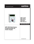
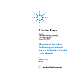
APG-XT
APG-HPD
Operating Manual
Internal APG (Analog
Programming) Interface
for XT/HPD Series
Programmable DC
Power Supply
Operating Manual for
Internal APG (Analog
Programming) Interface
for XT 60 Watt and
HPD 300 Watt Series
Programmable DC
Power Supply
Limited
Warranty
What does this warranty cover and how long does it last?
This Limited Warranty is provided by Xantrex Technology, Inc. (“Xantrex”) and
covers defects in workmanship and materials in your Internal APG Interface card.
This warranty lasts for a Warranty Period of 5 years from the date of purchase at
point of sale to you, the original end user customer.
What will Xantrex do?
Xantrex will, at its option, repair or replace the defective product free of charge,
provided that you notify Xantrex of the product defect within the Warranty Period,
and provided that Xantrex through inspection establishes the existence of such a
defect and that it is covered by this Limited Warranty.
Xantrex will, at its option, use new and/or reconditioned parts in performing
warranty repair and building replacement products. Xantrex reserves the right to use
parts or products of original or improved design in the repair or replacement. If
Xantrex repairs or replaces a product, its warranty continues for the remaining
portion of the original Warranty Period or 90 days from the date of the return
shipment to the customer, whichever is greater. All replaced products and all parts
removed from repaired products become the property of Xantrex.
Xantrex covers both parts and labor necessary to repair the product, and return
shipment to the customer via a Xantrex-selected non-expedited surface freight
within the contiguous United States and Canada. Alaska and Hawaii are excluded.
Contact Xantrex Customer Service for details on freight policy for return shipments
outside of the contiguous United States and Canada.
How do you get service?
If your product requires troubleshooting or warranty service, contact your merchant.
If you are unable to contact your merchant, or the merchant is unable to provide
service, contact Xantrex directly at:
ii
Phone:
604 422 8595
Toll Free North America:
1 800 667 8422
Fax:
604 421 3056
Email:
[email protected]
Operating Manual for APG for XT/HPD Series Power Supply
Direct returns may be performed according to the Xantrex Return Material
Authorization Policy described in your product manual. For some products, Xantrex
maintains a network of regional Authorized Service Centers. Call Xantrex or check
our website to see if your product can be repaired at one of these facilities.
In any warranty claim, dated proof of purchase must accompany the product and the
product must not have been disassembled or modified without prior written
authorization by Xantrex.
Proof of purchase may be in any one of the following forms:
•
•
•
The dated purchase receipt from the original purchase of the product at point of
sale to the end user, or
The dated dealer invoice or purchase receipt showing original equipment
manufacturer (OEM) status, or
The dated invoice or purchase receipt showing the product exchanged under
warranty
What does this warranty not cover?
This Limited Warranty does not cover normal wear and tear of the product or costs
related to the removal, installation, or troubleshooting of the customer’s electrical
systems. This warranty does not apply to and Xantrex will not be responsible for any
defect in or damage to:
a. the product if it has been misused, neglected, improperly installed, physically
damaged or altered, either internally or externally, or damaged from improper
use or use in an unsuitable environment;
b. the product if it has been subjected to fire, water, generalized corrosion,
biological infestations, and high input voltage from lightning strikes;
c. the product if repairs have been done to it other than by Xantrex or its authorized
service centers (hereafter “ASCs”);
d. the product if it is used as a component part of a product expressly warranted by
another manufacturer;
e. the product if its original identification (trade-mark, serial number) markings
have been defaced, altered, or removed.
Release 1.0
iii
Disclaimer Product
THIS LIMITED WARRANTY IS THE SOLE AND EXCLUSIVE WARRANTY PROVIDED
BY XANTREX IN CONNECTION WITH YOUR XANTREX PRODUCT AND IS, WHERE
PERMITTED BY LAW, IN LIEU OF ALL OTHER WARRANTIES, CONDITIONS,
GUARANTEES, REPRESENTATIONS, OBLIGATIONS AND LIABILITIES, EXPRESS
OR IMPLIED, STATUTORY OR OTHERWISE IN CONNECTION WITH THE
PRODUCT, HOWEVER ARISING (WHETHER BY CONTRACT, TORT, NEGLIGENCE,
PRINCIPLES OF MANUFACTURER’S LIABILITY, OPERATION OF LAW, CONDUCT,
STATEMENT OR OTHERWISE), INCLUDING WITHOUT RESTRICTION ANY
IMPLIED WARRANTY OR CONDITION OF QUALITY, MERCHANTABILITY OR
FITNESS FOR A PARTICULAR PURPOSE. ANY IMPLIED WARRANTY OF
MERCHANTABILITY OR FITNESS FOR A PARTICULAR PURPOSE TO THE EXTENT
REQUIRED UNDER APPLICABLE LAW TO APPLY TO THE PRODUCT SHALL BE
LIMITED IN DURATION TO THE PERIOD STIPULATED UNDER THIS LIMITED
WARRANTY.
IN NO EVENT WILL XANTREX BE LIABLE FOR ANY SPECIAL, DIRECT, INDIRECT,
INCIDENTAL OR CONSEQUENTIAL DAMAGES, LOSSES, COSTS OR EXPENSES
HOWEVER ARISING WHETHER IN CONTRACT OR TORT INCLUDING WITHOUT
RESTRICTION ANY ECONOMIC LOSSES OF ANY KIND, ANY LOSS OR DAMAGE TO
PROPERTY, ANY PERSONAL INJURY, ANY DAMAGE OR INJURY ARISING FROM OR
AS A RESULT OF MISUSE OR ABUSE, OR THE INCORRECT INSTALLATION,
INTEGRATION OR OPERATION OF THE PRODUCT.
Exclusions If this product is a consumer product, federal law does not allow an exclusion of
implied warranties. To the extent you are entitled to implied warranties under federal
law, to the extent permitted by applicable law they are limited to the duration of this
Limited Warranty. Some states and provinces do not allow limitations or exclusions
on implied warranties or on the duration of an implied warranty or on the limitation
or exclusion of incidental or consequential damages, so the above limitation(s) or
exclusion(s) may not apply to you. This Limited Warranty gives you specific legal
rights. You may have other rights which may vary from state to state or province to
province.
iv
Operating Manual for APG for XT/HPD Series Power Supply
Information
WITHOUT LIMITING THE GENERALITY OF THE FOREGOING, UNLESS
SPECIFICALLY AGREED TO BY IT IN WRITING, XANTREX
a. MAKES NO WARRANTY AS TO THE ACCURACY, SUFFICIENCY OR SUITABILITY
OF ANY TECHNICAL OR OTHER INFORMATION PROVIDED IN MANUALS OR
OTHER DOCUMENTATION PROVIDED BY IT IN CONNECTION WITH THE
PRODUCT; AND
b. ASSUMES NO RESPONSIBILITY OR LIABILITY FOR LOSSES, DAMAGES,
COSTS OR EXPENSES, WHETHER SPECIAL, DIRECT, INDIRECT,
CONSEQUENTIAL OR INCIDENTAL, WHICH MIGHT ARISE OUT OF THE USE OF
SUCH INFORMATION.
THE USE OF ANY SUCH INFORMATION WILL BE ENTIRELY AT THE USER’S RISK.
WARNING: Please refer to your product user manual for limitations on uses of the product.
Limitations Specifically, please note that this power supply is not intended for use in connection
on Use with life support systems and Xantrex makes no warranty or representation in
connection with any use of the product for such purposes.
Xantrex Technology, Inc.
8999 Nelson Way
Burnaby, British Columbia
Canada V5A 4B5
Information Please record the following information when you first open your Power Supply
About Your package:
Power
Model Number
______________________________________________
Supply
Serial Number
______________________________________________
Purchased From
______________________________________________
Purchase Date
______________________________________________
Release Release 1.0 (2002-07)
Copyright © 2002 Xantrex Technology Inc. All rights reserved.
Printed in Canada
Release 1.0
v
Warnings Warnings and cautions are defined and formatted in this manual as shown below.
and
Cautions
WARNING
Describes a potential hazard which could result in injury or death, or, a procedure
which, if not performed correctly, could result in injury or death.
!
CAUTION
Describes a procedure which, if not performed correctly, could result in damage
to data, equipment, or systems.
Power
Supply
Safety
WARNING—High Energy and High Voltage
Exercise caution when using and calibrating a power supply. High energy levels
can be stored at the output voltage terminals on a power supply in normal
operation. In addition, potentially lethal voltages exist in the power circuit and on
the output and sense connectors of a power supply with a rated output greater
than 40 V. Filter capacitors store potentially dangerous energy for some time after
power is removed.
!
vi
CAUTION
Operate the power supply in an environment free of flammable gases or fumes. To
ensure that the power supply’s safety features are not compromised, use the
power supply as specified in this manual and do not substitute parts or make any
unauthorized modifications. Contact the service technician for service and repair
help. Repairs must be made by experienced service technicians only.
Operating Manual for APG for XT/HPD Series Power Supply
About This Manual
This manual is for the internal APG (Analog Programming) interface card for the XT
and HPD Series DC output power supplies. This manual provides you with
descriptions and specifications, user options, and configuration instructions which
enable you to manage the power supply from an external source.
This manual is designed for the user who is familiar with basic electrical theory
especially as it applies to the operation of power supplies. This implies a recognition
of Constant Voltage and Constant Current operation modes and the control of input
and output power, as well as the observance of safe techniques while effecting
supply or pin connections and any changes in switch settings.
Refer to your power supply manual for installation, configuration, and operating
procedures for your power supply.
Main Sections
Section 1 Features and Specifications Describes the power supply and lists
its features and specifications.
Section 2 Installation and Configuration Goes through basic setup
procedures. Describes inspection, and cleaning procedures. Includes additional
options for calibration adjustment.
Section 3 Operation Details information on remote programming, indicators
and protections.
Manual Revisions
The current release of this manual is listed below. Updates may be issued as an
addendum.
Release 1.0 (2002-07)
Release 1.0
vii
About This Manual
viii
Operating Manual for APG for XT/HPD Series Power Supply
Contents
About This Manual . . . . . . . . . . . . . . . . . . . . . . . . . . . . . . . . . . . . . . . . . . . . . . . . . . . vii
Section 1.
Features and
Specifications
Description . . . . . . . . . . . . . . . . . . . . . . . . . . . . . . . . . . . . . . . . . . . . . . . . . . . . . . . . . 11
Section 2.
Installation
and
Configuration
Introduction . . . . . . . . . . . . . . . . . . . . . . . . . . . . . . . . . . . . . . . . . . . . . . . . . . . . . . . . . 13
Features . . . . . . . . . . . . . . . . . . . . . . . . . . . . . . . . . . . . . . . . . . . . . . . . . . . . . . . . . . . 11
Specifications . . . . . . . . . . . . . . . . . . . . . . . . . . . . . . . . . . . . . . . . . . . . . . . . . . . . . . . 11
Initial Inspection . . . . . . . . . . . . . . . . . . . . . . . . . . . . . . . . . . . . . . . . . . . . . . . . . . . . . 13
Configuring . . . . . . . . . . . . . . . . . . . . . . . . . . . . . . . . . . . . . . . . . . . . . . . . . . . . . . . . . 14
Front panel . . . . . . . . . . . . . . . . . . . . . . . . . . . . . . . . . . . . . . . . . . . . . . . . . . . . . 14
Rear Panel . . . . . . . . . . . . . . . . . . . . . . . . . . . . . . . . . . . . . . . . . . . . . . . . . . . . . 15
Rear Panel Switch (S1) Defaults . . . . . . . . . . . . . . . . . . . . . . . . . . . . . . . . . . . . 15
Rear Panel J5 Connector . . . . . . . . . . . . . . . . . . . . . . . . . . . . . . . . . . . . . . . . . . . . . . 16
J5 Connector Pin Assignments . . . . . . . . . . . . . . . . . . . . . . . . . . . . . . . . . . . . . 16
Calibration Adjustment . . . . . . . . . . . . . . . . . . . . . . . . . . . . . . . . . . . . . . . . . . . . . . . . 17
Section 3.
Operation
Remote Programming. . . . . . . . . . . . . . . . . . . . . . . . . . . . . . . . . . . . . . . . . . . . . . . . . 19
Programming Output Voltage with a 0-10Vdc Voltage Source . . . . . . . . . . . . . 19
Programming Output Voltage with a 0-10k Resistance . . . . . . . . . . . . . . . . . . . 20
Programming Output Current with a 0-10 Vdc Voltage Source . . . . . . . . . . . . . 20
Programming Output Current with a 0-10k Resistance . . . . . . . . . . . . . . . . . . . 21
Programming with a Fixed +10V Reference . . . . . . . . . . . . . . . . . . . . . . . . . . . 21
Readback and Status Indicators. . . . . . . . . . . . . . . . . . . . . . . . . . . . . . . . . . . . . . . . . 22
Voltage and Current Readback . . . . . . . . . . . . . . . . . . . . . . . . . . . . . . . . . . . . . 22
Operating Mode Status . . . . . . . . . . . . . . . . . . . . . . . . . . . . . . . . . . . . . . . . . . . 22
Remote Programming Status. . . . . . . . . . . . . . . . . . . . . . . . . . . . . . . . . . . . . . . 22
Output Fail Flag . . . . . . . . . . . . . . . . . . . . . . . . . . . . . . . . . . . . . . . . . . . . . . . . . 22
Overvoltage Protection (OVP) . . . . . . . . . . . . . . . . . . . . . . . . . . . . . . . . . . . . . . . . . . 23
OVP Flag . . . . . . . . . . . . . . . . . . . . . . . . . . . . . . . . . . . . . . . . . . . . . . . . . . . . . . 23
Setting the OVP Trip Level. . . . . . . . . . . . . . . . . . . . . . . . . . . . . . . . . . . . . . . . . 23
TTL Shutdown . . . . . . . . . . . . . . . . . . . . . . . . . . . . . . . . . . . . . . . . . . . . . . . . . . . . . . 24
Tracking . . . . . . . . . . . . . . . . . . . . . . . . . . . . . . . . . . . . . . . . . . . . . . . . . . . . . . . . . . . 25
Release 1.0
ix
Contents
x
Operating Manual for APG for XT/HPD Series Power Supply
Section 1. Features and Specifications
Description
The Analog Programming (APG) Interface is an internal option card for analog
programming of XT and HPD Series DC power supplies with a 0-10Vdc
programming source or a 0-10kΩ resistance. A 25-pin female DSUB connector on
the unit's rear panel enables connections to the card.
Features
•
•
•
•
•
•
•
Programming output voltage and/or current limit using a 0-10Vdc programming
source or a 0-10kΩ resistance. Externally adjustable offset and range.
Fixed programming of output voltage and/or current limit using an available
10V reference (10mA max source)
0-10V readback of output voltage and current with externally adjustable offset
and range
Status signals for programming mode, operating mode, OVP (over voltage
protection) flag, and output fail flag
Adjustable OVP with reset and flag
TTL shutdown with selectable positive or negative logic
Tracking for multiple supplies of the same output
Specifications
Release 1.0
Remote Analog Programming
0-10Vdc for 0-100% of rated voltage or current ±0.1%
0-10kΩ for 0-100% of rated voltage or current ±0.1%
OVP Trip Range
3V to full output + 10%
Remote ON/OFF
2 to 25Vdc high. <0.8Vdc low. User-selectable logic
Tracking Accuracy
±1%
11
Section 1. Features and Specifications
Specifications
12
Operating Manual for APG for XT/HPD Series Power Supply
Section 2. Installation and Configuration
Introduction
We usually install the APG interface in a power supply at the factory. Your local
distributor or service center can also install the interface, especially for use in a
previously-purchased supply already on site.
Initial Inspection
!
CAUTION
If you remove the unit's cover, use proper static control techniques to avoid damage
to static-sensitive components on the printed circuit board.
On first receiving your unit, perform a quick physical check.
•
Ensure each package contains a power supply with its APG interface board
installed, and manuals for the power supply and the APG interface. Any
additional parts shipped with the power supply will be identified in the supply's
documentation.
Inspect the unit for any signs of physical damage such as scratches, cracks, or
broken switches, connectors, or displays.
Check the printed circuit board and components if you suspect internal damage.
•
•
If the unit is damaged, save all packing materials and notify the carrier immediately.
For additional information, please see the section titled, “Returning Power Supplies
to the Manufacturer” in the manual shipped with your complete unit.
!
Release 1.0
CAUTION
Use proper static control techniques to avoid damage to static-sensitive components
on the printed circuit board.
13
Section 2. Installation and Configuration
Configuring
Configuring
Configure and adjust the analog programming interface installed in your XT or HPD
DC power supply as indicated in this section. The front panel LEDs indicate when
V or I programming is selected (PGM), when TTL shutdown has occurred (S/D), and
when the supply exceeds the voltage trip point OVP). You can adjust the OVP right
at the front panel. You will find the main programming option switch and connector
on the unit's rear panel, see Figure 2.2.
Front panel
Figure 2.1 XT/HPD Front Panel with APG Interface Installed
(typical configuration)
14
Operating Manual for APG for XT/HPD Series Power Supply
Section 2. Installation and Configuration
Configuring
Rear Panel
Figure 2.2 XT/HPD Rear Panel with APG Interface
Rear Panel Table 2.1 Rear Panel Switch S1 Default Settings
Switch (S1) Setting Function
Defaults
S1-1
TTL Shutdown Logic Select
(OPEN=negative logic, CLOSED=positive logic)
S1-2
Resistive Current Program Select
S1-3
Remote Current Program Select
S1-4
Resistive Voltage Program Select
S1-5
Remote Voltage Program Select
S1-6
Tracking Select
Default: Local control (all switches OPEN).
Release 1.0
15
Section 2. Installation and Configuration
Rear Panel J5 Connector
Rear Panel J5 Connector
Make analog interface connections via the rear panel 25-pin female DSUB connector
designated J5. To provide the lowest noise performance, we recommend you use
shielded-twisted pair wiring for making connections from external circuits to the J5
connector. Use the shortest leads possible. Ground the shield to pin 6 (auxiliary
ground) on the J5 connector or to the chassis via one of the J5 connector screws.
Note:In order to maintain isolation of power supply output, any programming
source must also be an isolated source.
J5 Connector Table 2.2 J5 Connector Pin Assignments
Pin Pin Function
Assignments
1
Over Voltage Protection Flag
2
TTL Shutdown Return
3
Not Used
4
Program Return
5
Program Return
6
Auxiliary Ground
7
Remote Voltage Program Select*
8
Remote Current Program Select*
9
Voltage/Current Limit Mode Indicator
10
+ OUT
11
+ OUT
12
RTN
13
RTN
14
Not Used
15
TTL Shutdown
16
Current Limit Program
17
Voltage Program
18
Current Readback
19
Voltage Readback
20
+10 V Reference OUT (10 mA max.)
21
Output Fail Flag*
22
+ SNS
23
+ OUT
24
RTN
25
RTN SNS
* Negative Logic: LOW = ACTIVE
16
Operating Manual for APG for XT/HPD Series Power Supply
Section 2. Installation and Configuration
Calibration Adjustment
Calibration Adjustment
You can access most calibration potentiometers through the top of the unit, see
Figure 2.3. The exceptions are Voltage Program OFFSET and RANGE which are
on the unit's rear panel which can be seen on Figure 2.2.
Figure 2.3 APG Interface Calibration Adjustment Locations
Release 1.0
17
Section 2. Installation and Configuration
Calibration Adjustment
18
Operating Manual for APG for XT/HPD Series Power Supply
Section 3. Operation
Remote Programming
Remote programming allows control of the power supply's output voltage and/or
current limit to shift from local operation at the front panel voltage and current
controls to external analog input sources. As you vary the programming source, the
power supply's output varies proportionally over its output range.
When you select remote voltage programming, the voltage control knob on the front
panel will not work. The same situation applies when you select remote current
programming: the remote option overrides the current control knob on the front
panel.
!
CAUTION
The programming signal return is internally referenced to the return sense (RTN
SNS) potential of the power supply. Therefore, you may connect the remote
programming source return to the power supply circuit at ONLY ONE of the
following nodes:
•
•
•
APG Interface J5 connector pins 4 or 5 (program return), OR
power supply output return when remote sense not used, OR
power supply return sense (RTN SNS) when remote sense is connected.
If you do not observe this restriction, the power supply may operate erratically,
or, fuse F1 on the APG Interface PCB assembly may blow.
In order to maintain isolation of power supply output, use a programming source
which is also an isolated source.
Programming 1. Select remote voltage programming by moving the rear panel switch S1-5
Output
(remote voltage program select) to the ON (closed) position.
Voltage with
Or, connect J5 pin 7 (remote voltage program select) to J5 pin 6 (auxiliary
a 0-10Vdc
ground). As these two control functions are wired in parallel, they function as a
Voltage
logic OR.
Source
2. Connect the voltage source between pin 17 (voltage program) and either pin 4 or
pin 5 (program return).
Release 1.0
19
Section 3. Operation
Remote Programming
3. Vary the external voltage from 0-10Vdc to cause the power supply output to vary
from 0-100% of rated output voltage. You may set the power supply's output
current limit using another source or the front panel current limit control.
Note:Access the zero offset adjustment through the rear panel hole labelled
OFFSET. Access the full scale calibration adjustment through the rear panel hole
labelled RANGE. See Figure 2.2, pg. 15.
Programming 1. Select remote voltage programming by moving the rear panel switch S1-5
Output
(remote voltage program select) to the ON (closed) position.
Voltage with
Or, connect J5 pin 7 (remote voltage program select) to J5 pin 6 (auxiliary
a 0-10k
ground). As these two control functions are wired in parallel, they function as a
Resistance
logic OR.
2. Set rear panel switch S1-4 (resistive voltage program select) to the ON (closed)
position.
3. Connect a variable resistor between pin 17 (voltage program) and either pin 4 or
pin 5 (program return).
4. Adjust the resistance from 0-10kΩ to vary the power supply output from 0-100%
of rated output voltage. You may set the power supply's output current limit
using another source or the front panel current limit control.
Programming 1. Select remote current limit programming by moving the rear panel switch S1-3
Output
(remote current program select) to the ON (closed) position.
Current with
Or, connect J5 pin 8 (remote current program select) to J5 pin 6 (auxiliary
a 0-10 Vdc
ground). As these two control functions are wired in parallel, they function as a
Voltage
logic OR.
Source
2. Connect the voltage source between J5 pin 16 (current program, positive) and
either pin 4 or pin 5 (program return).
3. Vary the external voltage from 0-10Vdc to cause the power supply current limit
to vary from 0-100% of rated output. You may set the power supply's output
voltage using another source or the front panel voltage control.
Access the zero offset adjustment and full range scale adjustment through top cover
slots as shown in Figure 2.3, pg. 17.
20
Operating Manual for APG for XT/HPD Series Power Supply
Section 3. Operation
Remote Programming
Programming 1. Select remote current programming by external resistance by moving the rear
Output
panel switch S1-3 (remote current program select) to the ON (closed) position.
Current with
Or, connect J5 pin 8 (remote current program select) to J5 pin 6 (auxiliary
a 0-10k
ground). As these two control functions are wired in parallel, they function as a
Resistance
logic OR.
2. Set rear panel switch S1-2 (resistive current program select) to the ON (closed)
position.
3. Connect a variable resistance between J5 pin 16 and either pin 4 or pin 5
(program return).
4. Adjust the resistance from 0-10kΩ to vary the power supply current limit from
0-100% of rated output. You may set the power supply's output voltage using
another source or the front panel voltage control.
Programming The APG Interface J5 connector provides a +10 V reference output at pin 20 for
with a Fixed applications which require a fixed output voltage and/or current limit. The current
+10V from this output must be less than 10 mA.
Reference
To program output voltage:
1. Connect resistor A between J5 connector pin 20 (+10 V reference out) and pin
17 (voltage program).
2. Connect resistor B between pin 17 (voltage program) and either pin 4 or 5
(program return).
To program current limit, follow the procedure used to set up for programming
output voltage, substituting pin 16 (current program) for pin 17.
+10 V
J5-20
VOMAX RB
Vo = -------------RA + RB
RA
Vpgm
J5-17
Where:
Vo = programmed output of power supply
RB
VoMAX = rated maximum output of power supply
J5-4
RA + RB > 1k
Figure 3.1 Programming with a Fixed +10V Reference
Release 1.0
21
Section 3. Operation
Readback and Status Indicators
Readback and Status Indicators
Voltage and Voltage Readback
Current • Connect a meter between J5 connector pin 19 (voltage readback) and either pin
Readback
4 or 5 (program return).
Range: 0-10V = 0-100% full rated voltage output of power supply
Current Readback
•
Connect a meter between J5 connector pin 18 (current readback) and either pin
4 or 5 (program return).
Range: 0-10V = 0-100% full rated current output of power supply
Note:The voltage and current readback signals have adjustable offset and range.
These adjustments are accessible from the top of the power supply (see Figure 2.3,
pg. 17). The adjustments are independent of other power supply calibrations or
adjustments such that APG readback can be zero and range calibrated without
affecting other power supply parameters.
Operating •
Mode Status
Connect voltmeter between J5 connector pin 9 (voltage/current limit mode
indicator) and pin 6 (auxiliary ground).
Voltage Mode: active low open collector
Current Mode: high impedance open collector
Remote Remote programming status is available via J5 connector pins 7 (remote voltage
Programming program select) and 8 (remote current program select). Reference to J5 connector at
Status either pin 4 or 5 (program return).
J5-7 LOW = Remote Voltage Program, HIGH=Local Front Panel Control
J5-8 LOW = Remote Current Program, HIGH=Local Front Panel Control
Output Fail The Output Fail Flag (J5 connector pin 21) signal is HIGH (open collector) when any
Flag one of the following conditions is true:
•
•
•
•
22
AC input to the power supply is below operating limits.
Over voltage protection is activated.
TTL shutdown is active.
Sense line protect circuit is active (excessive load line drop or load line(s) not
connected or fuse(s) in power supply blown).
Operating Manual for APG for XT/HPD Series Power Supply
Section 3. Operation
Overvoltage Protection (OVP)
Overvoltage Protection (OVP)
The OVP circuit is designed to protect the load in the event of a remote programming
error, incorrect voltage control adjustment, or power supply failure. The protection
circuit monitors the output and reduces the output voltage and current to zero
whenever a preset voltage limit is exceeded. A red LED on the front panel indicates
when the OVP circuit has been activated. Set the OVP trip level at the front panel.
OVP Flag When the OVP has been activated, a signal of nominal +10V through 10k will be
present at pin J5-1. When no OVP condition exists, this signal will be 0V.
Setting the 1. Turn the power supply OFF.
OVP Trip 2. Insert a small, flat-bladed screwdriver through the OVP ADJ (OVP Adjust) hole
Level
in the front panel to turn the adjusting screw fully clockwise (one-turn screw).
3. Turn the unit ON and set the output to the desired trip voltage.
4. Slowly turn the adjusting screw counterclockwise until the red OVP indicator
lamp lights.
5. Turn the POWER switch to OFF.
6. Turn the voltage control knob to minimum.
7. Turn the POWER switch back ON and increase the voltage to check that the
power supply shuts off the output at the set voltage. Reference to J5 connector
pin 6 (auxiliary ground).
8. Reset the OVP circuit after activation by removing the overvoltage condition
and powering the unit OFF and back ON, or, by momentarily activating the TTL
remote shut down circuit. See “TTL Shutdown” for information about shut
down circuit operation.
Release 1.0
23
Section 3. Operation
TTL Shutdown
TTL Shutdown
TTL Shutdown allows the output of the power supply to be disabled by a logic level
signal. This input is optically isolated from the power supply output and will
withstand a highpot test potential of 600Vac minimum. When TTL shutdown is
activated, the front panel LED comes on.
•
•
Connect the signal source between J5 connector pins 15 (TTL
shutdown/positive) and 2 (TTL shutdown return/negative).
Set rear panel switch S1-1 (TTL shutdown) to ON (closed) to obtain positive
logic (high signal enables output). The factory-set default is switch OPEN for
negative logic (high signal disables power supply output).
Switch SW1-1 Setting
TTL Signal Level
Output Condition
OPEN (Negative logic)
HIGH
LOW
OFF
ON
CLOSED (Positive logic)
HIGH
LOW
ON
OFF
Notes:Minimum activation signal required: 2V at 500µA
Maximum activation signal allowed : 25Vdc
24
Operating Manual for APG for XT/HPD Series Power Supply
Section 3. Operation
Tracking
Tracking
For tracking +/- outputs, use the following set-up:
•
•
•
Set slave unit rear panel switch S1-5 (remote voltage program select) and switch
S1-6 (tracking select) to ON (closed).
Connect master return (J5 connector pins 12, 13, or 24) to slave +OUT (J5
connector pins 10, 11, or 23).
Connect master +OUT (J5 connector pins 10, 11, or 23) to slave voltage program
input (J5 connector pin 17).
Notes:
1. Master/slave power supplies must have the same output ratings.
2. Set switch S2 on the slave unit's APG Interface PCB to the correct model
number (factory preset). This requires that you remove the power supply cover.
3. Slave tracking can be calibrated by adjusting the unit's offset and range
potentiometers. See “Calibration Adjustment” on page 17.
4. As the slave is referenced to the master's output, the noise and ripple on the slave
may increase. In addition, if the master's output decreases due to current limit
acting, the output voltage of the slave will follow.
Figure 3.2 Master/Slave Tracking Configuration
Release 1.0
25
Section 3. Operation
Tracking
26
Operating Manual for APG for XT/HPD Series Power Supply
Xantrex Technology Inc.
8999 Nelson Way
Burnaby, British Columbia
Canada V5A 4B5
604 422 8595 Tel
604 421 3056 Fax
800 667 8422 Toll Free North America
[email protected]
www.xantrex.com
TM-5A6H-01XN
PRINTED IN CANADA