1
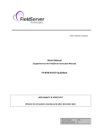
-
A Sierra Monitor Company
Driver Manual
(Supplement to the FieldServer Instruction Manual)
FS-8700-132 Gamewell FCI E3 Series Serial
Driver
APPLICABILITY & EFFECTIVITY
Effective for all systems manufactured after September 2008
Driver Version:
Document Revision:
1.01
4
FS-8700-132 Gamewell FCI-E3 Driver Manual
Table of Contents
TABLE OF CONTENTS
1.
Gamewell FCI-E3 Series Serial Driver Description...................................................... 3
2.
Driver Scope of Supply ................................................................................................. 4
2.1.
Supplied by FieldServer Technologies for this driver.................................................. 4
2.2.
Provided by the Supplier of 3rd Party Equipment ........................................................ 4
2.2.1. Required 3rd Party Hardware .................................................................................. 4
3.
Hardware Connections ................................................................................................. 5
4.
Configuring the FieldServer as a Gamewell FCI-E3 Series Serial Driver Client ........ 6
4.1.
Data Arrays/Descriptors ............................................................................................. 6
4.2.
Client Side Connection Descriptions .......................................................................... 7
4.3.
Client Side Node Descriptors ..................................................................................... 8
4.4.
Client Side Map Descriptors....................................................................................... 8
4.4.1. FieldServer Related Map Descriptor Parameters .................................................... 8
4.4.2. Driver Related Map Descriptor Parameters............................................................. 9
4.5.
Map Descriptor Example 1 – Sensor / Module Events...............................................10
4.6.
Map Descriptor Example 2 – Bit Storage ..................................................................11
5.
Configuring the FieldServer as a Gamewell FCI-E3 Series Serial Driver Server......12
Appendix A.
Advanced Topics..........................................................................................13
Appendix A.1. Events and Event Categories.......................................................................13
Appendix A.2. Extending the Event Table ...........................................................................14
Appendix A.3. How Data is stored.......................................................................................14
Appendix A.4. Panel Synchronization .................................................................................16
Appendix A.5. What happens when the panel sends a Reset Message ..............................16
Appendix A.5.1. Networked Panels..................................................................................16
Appendix B.
Driver Error Messages. ................................................................................17
Appendix B.1. Driver Stats Exposed. ..................................................................................19
FieldServer Technologies 1991 Tarob Court Milpitas, California 95035 USA Web: www.fieldserver.com
Tel: (408) 262 2299 Fax: (408) 262 2269 Toll Free: (888) 509 1970 email: [email protected]
FS-8700-132 Gamewell FCI-E3 Driver Manual
1.
Page 3 of 20
Gamewell FCI-E3 Series Serial Driver Description
The Gamewell FCI-E3 Series System Control Units are manufactured by Fire Control Instruments. An E3
Panel with an enabled serial port can transmit data to a FieldServer which can, in turn, make the data
available to other devices including those which communicate using different protocols (e.g. BACnet)
This passive Client driver does not poll for data, nor does it send data or commands to the E3. Messages
received from the E3 are analyzed and are then either discarded or used to update the FieldServer’s
internal Data Arrays. The action depends on which types of events, the type of device generating the
event and device address the FieldServer has been configured to process. Once stored in the
FieldServer the data is available to be read or written using other protocols such as BACnet.
No automatic panel data synchronization technique exists. The data in the FieldServer and the panel
status have to be synchronized manually. This typically requires a panel reset.
Since the driver cannot send data or commands to the E3 it cannot be used to acknowledge, silence or
reset alarms and other events.
The driver can process messages from networked panels. The driver connects to the main panel.
Subsidiary panels are configured to send event data to the main panel which then sends messages to the
FieldServer. Node information is sent in the line preceding the event and the driver uses this to
determine the panel at which the event originated and to store data appropriately.
The driver provides both Client and Server emulation. The Server side of the driver is intended to support
FieldServer’s Quality Assurance program and is not intended to provide complete emulation of an E3 and
is thus not fully documented. Should you require the Server side functionality to be documented and
enhanced, please contact FieldServer’s sales group.
Max Nodes Supported
FieldServer
Mode
Nodes
Client
1
Server
N/A
Comments
1 Node per serial port. If there is more than one alarm panel they can be
networked and configured to send event data to the primary panel. The driver
can process messages which identify the node of origin.
Server side is not supported. See description.
FieldServer Technologies 1991 Tarob Court Milpitas, California 95035 USA Web: www.fieldserver.com
Tel: (408) 262 2299 Fax: (408) 262 2269 Toll Free: (888) 509 1970 email: [email protected]
FS-8700-132 Gamewell FCI-E3 Driver Manual
2.
Page 4 of 20
Driver Scope of Supply
2.1.
Supplied by FieldServer Technologies for this driver
FieldServer Technologies
PART #
FS-8917-16
FS-8700-132
2.2.
Description
Pigtail cable for RJ45 Port for RS-232 use
Driver Manual.
Provided by the Supplier of 3rd Party Equipment
2.2.1.
Required 3rd Party Hardware
ILI-MB-E3 Board
FieldServer Technologies 1991 Tarob Court Milpitas, California 95035 USA Web: www.fieldserver.com
Tel: (408) 262 2299 Fax: (408) 262 2269 Toll Free: (888) 509 1970 email: [email protected]
FS-8700-132 Gamewell FCI-E3 Driver Manual
3.
Page 5 of 20
Hardware Connections
The FieldServer is connected to the FCI-E3 panel as shown in the connection drawing.
Part of FCI-E3 Panel ILI-MB-E3 Board
1
2
3
4
TB6
Blue/white
Orange/White
Brown
FieldServer Part #
FS-8917-16
Pigtail for RJ45
Port
Connect to one of the RS-232
Ports on the FieldServer
RJ45
8
FieldServer
1
P1
Connector Pinouts
Wire Color
Brown
White/Orange
Blue/white
RJ-45
Pin Signal
1
Rx
8
Tx
5
GND
FCI-E3
Signal
+ve
-ve
Signal Common Reference
Pin
2
1
4
FieldServer Technologies 1991 Tarob Court Milpitas, California 95035 USA Web: www.fieldserver.com
Tel: (408) 262 2299 Fax: (408) 262 2269 Toll Free: (888) 509 1970 email: [email protected]
FS-8700-132 Gamewell FCI-E3 Driver Manual
4.
Page 6 of 20
Configuring the FieldServer as a Gamewell FCI-E3 Series Serial Driver Client
For a detailed discussion on FieldServer configuration, please refer to the FieldServer Configuration
Manual. The information that follows describes how to expand upon the factory defaults provided in the
configuration files included with the FieldServer (See “.csv” sample files provided with the FieldServer).
This section documents and describes the parameters necessary for configuring the FieldServer to
communicate with a FCI Series E3.
4.1.
Data Arrays/Descriptors
The configuration file tells the FieldServer about its interfaces, and the routing of data required. In
order to enable the FieldServer for Gamewell FCI-E3 Series Serial Driver communications, the driver
independent FieldServer buffers need to be declared in the “Data Arrays” section, the destination
device addresses need to be declared in the “Client Side Nodes” section, and the data required from
the Servers needs to be mapped in the “Client Side Map Descriptors” section. Details on how to do
this can be found below.
Note that in the tables, * indicates an optional parameter, with the bold legal value being the default.
Section Title
Data_Arrays
Column Title
Function
Data_Array_Name
Provide name for Data Array
Data_Array_Format
Provide data format. Each Data Array
can only take on one format.
Data_Array_Length
Number of Data Objects. Must be
larger than the data storage area
required by the Map Descriptors for the
data being placed in this array.
Legal Values
Up to 15 alphanumeric
characters
Float, Bit, UInt16, SInt16,
Packed_Bit, Byte,
Packed_Byte,
Swapped_Byte
1-10,000
Example
//
Data Arrays
Data_Arrays
Data_Array_Name,
DA_AI_01,
DA_AO_01,
DA_DI_01,
DA_DO_01,
Data_Array_Format,
UInt16,
UInt16,
Bit,
Bit,
Data_Array_Length
200
200
200
200
FieldServer Technologies 1991 Tarob Court Milpitas, California 95035 USA Web: www.fieldserver.com
Tel: (408) 262 2299 Fax: (408) 262 2269 Toll Free: (888) 509 1970 email: [email protected]
FS-8700-132 Gamewell FCI-E3 Driver Manual
4.2.
Page 7 of 20
Client Side Connection Descriptions
Section Title
Connections
Column Title
Port
Protocol
Baud*
Function
Specify which port the device is connected to the FieldServer
Specify protocol used
Specify baud rate
Vendor documentation indicated that the only supported Baud
rate was 9600. During testing we learned this was not true. The
driver was tested at 57600 and 9600 baud. Testing at 115200
Baud produced intermittent result and should not be used.
Legal Values
1
P1-P8
FCI_E3
9600, 57600
(Vendor
Limitation)
None
–
(Vendor
Limitation)
8
(Vendor
Limitation)
1
(Vendor
Limitation)
Parity*
Specify parity
Data_Bits*
Specify data bits
Stop_Bits*
Specify stop bits
Handshaking*
The E3 series panels do not support hand shaking.
Example
//
Client Side Connections
Connections
Port,
P1,
Protocol,
FCI_E3,
Baud,
9600,
Parity
None
1
Not all ports shown are necessarily supported by the hardware. Consult the appropriate Instruction
manual for details of the ports available on specific hardware.
FieldServer Technologies 1991 Tarob Court Milpitas, California 95035 USA Web: www.fieldserver.com
Tel: (408) 262 2299 Fax: (408) 262 2269 Toll Free: (888) 509 1970 email: [email protected]
FS-8700-132 Gamewell FCI-E3 Driver Manual
4.3.
Page 8 of 20
Client Side Node Descriptors
Section Title
Nodes
Column Title
Function
Node_Name
Legal Values
Up to 32 alphanumeric
characters
Provide name for Node
Node_ID
Protocol
FCI_Reset_Action_Option*
Connection
Only
required
for
networked
configurations. Set the Node_ID of the
local panel to zero, and create one Node
Descriptor for each panel setting the
Node_ID to the panel number.
Specify protocol used
Only required for networked
configurations:
When not specified or set to
‘Reset_by_any_Node ‘ then the driver
will reset the data array points
associated with the given node
irrespective of the reset message’s
origin.
When set to ‘Reset_by_this_Node_Only’
then the driver only resets the data
associated with the given node if the
reset originated from the same node.
Specify which port the device is
connected to the FieldServer
Whole numbers 0,1,2,3 …
FCI_E3
Reset_by_any_Node,
Reset_by_this_Node_Only
P1-P8
2
Example
//
Client Side Nodes
Nodes
Node_Name,
Panel-01,
4.4.
Protocol,
FCI_E3,
Connection
P8
Client Side Map Descriptors
4.4.1.
FieldServer Related Map Descriptor Parameters
Column Title
Map_Descriptor_Name
Data_Array_Name
Data_Array_Offset
Function
Function
Name
of
this
Map
Descriptor
Name of Data Array
where data is to be stored
in the FieldServer
Starting location in Data
Array
Function of Client Map
Descriptor.
Legal Values
Up
to
32
alphanumeric
characters
One of the Data Array names
from “Data Array” section above
0 to maximum specified in
“Data Array” section above
Server, Passive_Client
2
Not all ports shown are necessarily supported by the hardware. Consult the appropriate Instruction
manual for details of the ports available on specific hardware.
FieldServer Technologies 1991 Tarob Court Milpitas, California 95035 USA Web: www.fieldserver.com
Tel: (408) 262 2299 Fax: (408) 262 2269 Toll Free: (888) 509 1970 email: [email protected]
FS-8700-132 Gamewell FCI-E3 Driver Manual
4.4.2.
Driver Related Map Descriptor Parameters
Column Title
Function
Node_Name
Name of Node to fetch data from
Event Type
Point Type
Relay/Loop/Zone
Number
Length*
Address
Store As*
DA_Bit_Name
Clear on Reset*
Page 9 of 20
This driver uses this parameter to determine the
suitability of a Map Descriptor when looking for a
location to store data from an incoming message.
A Map Descriptor may be defined to store only
‘Alarm’, ‘Fault’, ‘Trouble’ or ‘Other events.
Alternatively, specify “Any”
A table of events vs. categories is provided in
Appendix A.1
This driver uses this parameter to determine the
suitability of a Map Descriptor when looking for a
location to store data from an incoming message.
Ignored when the Point Type is ‘Panel’
Point Type = Relay 1..255
Point Type = Zone 1..8
Point Type = Loop 1..2
Point Type = Module 1..2
Point Type = Sensor 1..2
Each Map Descriptor defines storage locations for a
series of addresses. This parameter specifies the
length of the series.
This parameter is specific to Map Descriptors with
‘Event Type’ Module or Sensor. It specifies the
starting Module or Sensor number. The length
parameter then determines the range of the
Sensor/Module numbers
By default the driver stores using the ‘Index Value’
Method. If set to ‘Bit’ the driver will use the primary
Data Array to store using the ‘Bit Storage’ Method.
These methods are described in Appendix A.3
If the default ‘Store As’ is specified or if the
parameter is omitted then a secondary array can be
specified using this parameter - the driver will store
event data as ‘Bit Storage’ in the Secondary array
(and as ‘Index Values’ in the Primary array.) These
methods are described in Appendix A.3
If this parameter is specified it will prevent the Driver
resetting the Data Array points associated with the
Map Descriptor on reset.
Legal Values
One of the Node
Names specified in
Section 4.3
Any, Other, Fault,
Alarm, Trouble
Zone, Relay, Loop,
Sensor,
Module,
Panel
Whole Numbers
1, 2 , etc
1,2,3 .etc
Whole numbers
1..99
Bit, Index_Value
One of the Data
Array names from
“Data
Array”
section above
Yes, No
FieldServer Technologies 1991 Tarob Court Milpitas, California 95035 USA Web: www.fieldserver.com
Tel: (408) 262 2299 Fax: (408) 262 2269 Toll Free: (888) 509 1970 email: [email protected]
Map Descriptor Example 1 – Sensor / Module Events
Page 10 of 20
Unique
Map
Descriptor
Names
are
recommended.
Event Type,
Alarm,
The name of
the
Node
defined in the
Node
Descriptor
Node_Name,
Panel-01,
Address,
1,
Change this to
‘Sensor’
for
sensors.
Relay/Loop/Zone Number,
1,
Only
Alarm
events will be
stored.
Point Type,
Module,
FieldServer Technologies 1991 Tarob Court Milpitas, California 95035 USA Web: www.fieldserver.com
Tel: (408) 262 2299 Fax: (408) 262 2269 Toll Free: (888) 509 1970 email: [email protected]
The
driver
listens
passively
for
messages from
the Panel. It
cannot poll for
data.
Function,
Passive_Client,
Manual Station L1M21 00:37:28 01/01/99[CR][LF]
Data_Array_Offset,
0,
The Data Array
name
and
starting location
that data should
be stored.
Data_Array_Name,
DA_MODULE,
Client Side Map Descriptors
Map_Descriptors
Map_Descriptor_Name,
ModuleData1,
//
Example:
F.S.E.C.
:[CR][LF]
FIRST ALARM:
UP STAIRS N. ENT
Clear_on_Reset
Yes
In this example:
Module 1 to 99
The
address
specifies
the
starting Module
number and the
Length tells the
driver the range
of Modules.
Length,
99,
If messages from Loop 1, Module 1 to 99 are received then the Map Descriptor in this example will be used for storage. If modules occur on more
than one loop, one Map Descriptor is required per loop. In this example the event type is set to ‘Alarm’ so only “Alarm” events will be stored. The
“Event_Type” can be changed to suit the required data. If all events are required, the parameter should be set to “Any”.
4.5.
FS-8700-132 Gamewell FCI-E3 Driver Manual
Map Descriptor Example 2 – Bit Storage
Page 11 of 20
Client Side Map Descriptors
DA_RELAY,
RelayData,
0,
Data_Array_Offset,
Passive_Client,
Function,
Panel-01,
Node_Name,
Event
Type,
Any,
Point
Type,
Relay,
Remember that 2 elements per Relay, Module,
Sensor, Loop are used.
DA_Bit_Name is where secondary storage is
defined. Events are stored by setting
appropriate bits.
DB_Relay,
DA_Bit_Name,
Relay/Loop/Zone
Number,
1,
4,
Length,
Yes
Clear_on_Reset
Map Descriptors for
storing Relay, Loop,
Zone and Panel do not
need
the
address
specified.
-,
Address,
FieldServer Technologies 1991 Tarob Court Milpitas, California 95035 USA Web: www.fieldserver.com
Tel: (408) 262 2299 Fax: (408) 262 2269 Toll Free: (888) 509 1970 email: [email protected]
Data_Array_Name is where the
primary DA is specified. Index
values are stored here
Data_Array_Name,
Map_Descriptor_Name,
Map_Descriptors
//
This example defines storage location for Relay Point events. The example would work for all other point types. In the example, both primary and
secondary storage Data Arrays have been specified. The driver stores index values in the primary array. Each new event for a particular relay will
overwrite the value stored previously. In the Bit Array, the driver sets the bit corresponding to the event, leaving other bits unchanged – thus the
secondary storage can be used to determine if more than one event is active at a time.
4.6.
FS-8700-132 Gamewell FCI-E3 Driver Manual
FS-8700-132 Gamewell FCI-E3 Driver Manual
5.
Page 12 of 20
Configuring the FieldServer as a Gamewell FCI-E3 Series Serial Driver Server
The server side of the driver is intended to support FieldServer’s Quality Assurance program and is not
intended to provide complete emulation of an E3 and is thus not fully documented. Should you require
the Server side functionality to be documented and enhanced, please contact FieldServer’s sales group.
FieldServer Technologies 1991 Tarob Court Milpitas, California 95035 USA Web: www.fieldserver.com
Tel: (408) 262 2299 Fax: (408) 262 2269 Toll Free: (888) 509 1970 email: [email protected]
FS-8700-132 Gamewell FCI-E3 Driver Manual
Page 13 of 20
Appendix A. Advanced Topics
Appendix A.1.
Events and Event Categories
The driver reports the event cause using the matching index value. There are 4 event categories:
1 = Other
3 = Alarm
2 = Fault
4 = Trouble
The message category must match the ‘Event Type’ parameter specified on a Map Descriptor before
that Map Descriptor can be considered for storage of the message data.
Index
1
2
3
4
5
6
7
8
9
10
11
12
13
14
15
16
17
18
19
20
21
22
23
24
25
26
27
28
29
30
31
32
33
34
35
36
37
38
39
40
41
42
43
44
45
46
47
48
3
Category
FCI_EVENT_TYPE_FAULT
FCI_EVENT_TYPE_OTHER
FCI_EVENT_TYPE_OTHER
FCI_EVENT_TYPE_OTHER
FCI_EVENT_TYPE_OTHER
FCI_EVENT_TYPE_OTHER
FCI_EVENT_TYPE_OTHER
FCI_EVENT_TYPE_OTHER
FCI_EVENT_TYPE_OTHER
FCI_EVENT_TYPE_OTHER
FCI_EVENT_TYPE_OTHER
FCI_EVENT_TYPE_OTHER
FCI_EVENT_TYPE_OTHER
FCI_EVENT_TYPE_OTHER
FCI_EVENT_TYPE_OTHER
FCI_EVENT_TYPE_OTHER
FCI_EVENT_TYPE_OTHER
FCI_EVENT_TYPE_OTHER
FCI_EVENT_TYPE_OTHER
FCI_EVENT_TYPE_ALARM
FCI_EVENT_TYPE_OTHER
FCI_EVENT_TYPE_OTHER
FCI_EVENT_TYPE_OTHER
FCI_EVENT_TYPE_OTHER
FCI_EVENT_TYPE_OTHER
FCI_EVENT_TYPE_OTHER
FCI_EVENT_TYPE_OTHER
FCI_EVENT_TYPE_OTHER
FCI_EVENT_TYPE_OTHER
FCI_EVENT_TYPE_OTHER
FCI_EVENT_TYPE_OTHER
FCI_EVENT_TYPE_OTHER
FCI_EVENT_TYPE_OTHER
FCI_EVENT_TYPE_TRBLE
FCI_EVENT_TYPE_OTHER
FCI_EVENT_TYPE_OTHER
FCI_EVENT_TYPE_OTHER
FCI_EVENT_TYPE_OTHER
FCI_EVENT_TYPE_OTHER
FCI_EVENT_TYPE_OTHER
FCI_EVENT_TYPE_OTHER
FCI_EVENT_TYPE_OTHER
FCI_EVENT_TYPE_OTHER
FCI_EVENT_TYPE_OTHER
FCI_EVENT_TYPE_OTHER
FCI_EVENT_TYPE_OTHER
FCI_EVENT_TYPE_OTHER
FCI_EVENT_TYPE_OTHER
Event
"Fault"
"Short"
"Disconnect"3
"Comm Fault"
"Config Err"
"Eeprom Bad"
"Reset"
"Silence"
"Cross Zone"3
"Acknwldgd"
"Walk Test"
"Alarm Test"
"SPVSN Test"
"Fault Test"
"Fire Drill"
"Batt Test"
"PRGM Mode"
"Action"
"Loop Break"
"Alarm"
"P.A.S."
"Off-Normal"
"RZA Fault"3
"Verify"3
"CM Short"3
"Test Fail"
"Alert"
"Dirty"
"Very Dirty"
"Missing"
"Wrong Type"
"Extra Addr"
"Clock Err"3
"Trouble"3
"MLT Events"3
"Alrm Ackd"
"Outpt Fail"
"Tally Flt"
"AC Flt To"
"Trbl Ackd"
"Access"
"Netwrk Flt"
"NetGndFlt"
"Dact Fault"
"Node Msng"
"Node Xtra"
"Fans Off"
"Xzone Alrm"
Not defined in the spec
FieldServer Technologies 1991 Tarob Court Milpitas, California 95035 USA Web: www.fieldserver.com
Tel: (408) 262 2299 Fax: (408) 262 2269 Toll Free: (888) 509 1970 email: [email protected]
FS-8700-132 Gamewell FCI-E3 Driver Manual
Appendix A.2.
Page 14 of 20
Extending the Event Table
New event causes may be added to the Event Table and the index value or category of existing event
causes modified by adding a section to the configuration CSV file. The examples below illustrate this:
Example 1: Index value of 'Trouble' is updated to a new value of 100
Driver_Table
Event_Type_Description,
TROUBLE,
Event_Type_Index_Value,
100,
Event_Type_Category ,
4,
Protocol
FCI_E3
Example 2: New Entry is added
Since it has been added as category=3, only Map Descriptors with 'Event Type' set to “Alarm” or
“Any” will capture messages with this event description
Driver_Table
Event_Type_Description,
DESTROYED,
Event_Type_Index_Value,
51,
Event_Type_Category,
3,
Protocol
FCI_E3
For categories use the following values
'Other' = 1
'Fault' = 2
'Alarm' = 3
'Trouble' = 4
Appendix A.3.
How Data is stored
All messages shorter than 102 characters are discarded unless they contain information identifying
the networked/local panel. All other messages are processed as follows:
• The driver determines if the message is a Zone, Relay, Loop, Sensor, Module or Panel message.
• The driver finds all Map Descriptors with matching ‘Point Type’ parameters.
• The event category is determined.
• Map Descriptor selection is refined based on whether the ‘Event Type’ matches or has been
defined as “Any”
• The driver determines the Loop. Relay, Zone, Sensor and Module numbers from the message
and refines its selection of Map Descriptors by selecting those that match the values determined
from the message.
• The selected Map Descriptors are now used to determine a Data Array and offset at which to
store the data.
• Finally the driver checks the ‘Store As’ parameter. If it hasn’t been specified then ‘Index Value’
storage is assumed. If it has been specified as ‘Bits’ then the driver will perform ‘Bit Storage’. In
cases where the Map Descriptor has both a primary and secondary Data Array, the driver will use
‘Index Value’ storage using the primary data array and ‘Bit Storage’ using the secondary array.
FieldServer Technologies 1991 Tarob Court Milpitas, California 95035 USA Web: www.fieldserver.com
Tel: (408) 262 2299 Fax: (408) 262 2269 Toll Free: (888) 509 1970 email: [email protected]
Page 15 of 20
Data_Array_Offset,
0,
0,
0,
0,
0,
Event Type,
ANY,
ALARM,
FAULT,
TROUBLE,
OTHER,
Point Type,
Module,
Module,
Module,
Module,
Module,
Relay/Loop/Zone Number,
1,
1,
1,
1,
1,
Address,
1,
1,
1,
1,
1,
Length,
99,
99,
99,
99,
99,
Clear_on_Reset,
Yes,
Yes,
Yes,
Yes,
Yes,
DA_Bit_Name
DB_MODU
DB_MODU_A
DB_MODU_F
DB_MODU_T
DB_MODU_O
FieldServer Technologies 1991 Tarob Court Milpitas, California 95035 USA Web: www.fieldserver.com
Tel: (408) 262 2299 Fax: (408) 262 2269 Toll Free: (888) 509 1970 email: [email protected]
Message = “TROUBLE:
QZUb L1M22 << Chief's Office >>
5:24:00 3/03/93”
• This message reports status for Loop 1 Module 22. Since all the MD’s in the example have a ‘Point Type’=‘Module’, they are all considered
for storage.
• The driver looks in the Event Table and finds it has an index value of 34 and a category of 4 (Trouble). Only the MD’s with “Event Type” set to
“Any” and “Trouble” are now considered.
• Since the value of the ‘Relay/Loop/Zone’ parameter matches the Loop number in the message, these MD’s remain in contention.
• The Module number of 22 is compared with the MD’s Address and Length Parameters. The Address is the starting number and the length
defines the range. Both Map Descriptors have addresses of 1 and length of 99 and thus both are still selected because the Module of 22 falls
in this range.
• The driver calculates an offset based on the offset specified in the Map Descriptor and the Module number relative to the Map Descriptor
address:
Map Descriptor Offset = 0
Map Descriptor Address = 1
Message Module = 22
Module 1’s data is stored at offset 0 and hence Module 22’s data will be stored at offset 21. The driver stores the value 34 at offset 21
overwriting any data previously stored at that location. This is ‘Index Value’ Storage.
• Secondary storage has been defined using the ‘DA_Bit_Name’ Data Array. The driver doubles the offset as two locations are used for each
address. The driver then reads the value found in the Data_Array, modifies it and writes it back. Since the index value is 34 the driver
th
nd
modifies the 34 bit – or expressed another way, the driver modifies the 2 bit (34-32) at offset+1.
nd
• Thus, the driver calculates the offset for Bit Storage as 2 x 21 = 42. The driver sees that bit 34 is 2 2 bit in the next offset and so the driver
reads DB_MODU:43, modifies the value by setting the 2nd bit on and then writing the modified value back. During the modification all other
bits are left intact. Thus using the Bit Storage method, a single Module (or sensor…) can keep track of multiple events.
Message = “FAULT:
AC Power
E3
0:00:04 1/01/92”
• This message does not report the status of a Zone, Relay, Loop, Sensor or Module and is therefore assumed to be a panel message. Since
there is no Map Descriptor with “Point Type” Panel, the message is ignored.
Map_Descriptors,
Data_Array_Name,
DA_MODU
,
DA_MODU_A,
DA_MODU_F,
DA_MODU_T,
DA_MPODU_O,
The following fragment is part of a Map Descriptor definition; some parameters have been omitted for the purposes of clarity.
Example:
FS-8700-132 Gamewell FCI-E3 Driver Manual
FS-8700-132 Gamewell FCI-E3 Driver Manual
Appendix A.4.
Page 16 of 20
Panel Synchronization
Manual synchronization is required. When the “Reset” button on the panel is pressed a message is
transmitted to the FieldServer, which clears the data in the FieldServer. After a reset the panel sends
messages to report all abnormal states. When all these messages have been processed the
FieldServer and panel will be synchronized. This process can be repeated at any time.
Appendix A.5.
What happens when the panel sends a Reset Message
When a panel sends a reset message the driver processes every single Map Descriptor, looking at
the ‘Clear on Reset’ parameter (See section 4.4.2). If the parameter is set to yes, then the driver sets
all the Data Array elements referenced by the Map Descriptor to zero by looking up the Data Array
Name, the Data Array offset and the length. The driver also clears the relevant sections of a Data
Array specified with the DA_Bit_Name parameter.
The process can take some time. For this reason, it is suggested that you take care not to set the
Map Descriptor length to a value larger than necessary.
Appendix A.5.1.
Networked Panels.
The driver can processes messages and store data from multiple panels provided that:
• The panels are connected in an FCI network and the panels are configured to report their
events to the main panel
• The main panel is configured to send the Node of origin in a message preceding the event
message. Consult with FCI for information on how to achieve this.
Example of message sent by a panel that is networked. The driver is dependent on seeing the
node of event origin included in parenthesis before each event message.
Node02:
MISSING
01/01/06
Acclimate
L1S041 00:17:06
Node55: 1st Floor Lobby
DISCONNECT RSTRD
01/15/06
Ion Detector
L1S024 09:51:44
Local:
FIRST ALARM
12/01/06
Photo Detector
L1S001 09:24:52
The main panel is identified as ‘Local’. The driver interprets this as Node_ID=0.
To capture events from multiple networked panels a Node Descriptor is required for each panel
with the appropriate Node_ID. Each Node requires a set of Map Descriptors.
FieldServer Technologies 1991 Tarob Court Milpitas, California 95035 USA Web: www.fieldserver.com
Tel: (408) 262 2299 Fax: (408) 262 2269 Toll Free: (888) 509 1970 email: [email protected]
FS-8700-132 Gamewell FCI-E3 Driver Manual
Page 17 of 20
Appendix B. Driver Error Messages.
Message
FCI_E3:#1 FYI. Use a DA called <%s> to expose
diagnostic info., FCI_E3_STATS_DA )
FCI_E3:#2 FYI. Added Event Desc=<%s> Index=%d
Categ=%d
,
new_event_desc
,
new_event_desc_index_value , new_event_desc_categ ) ;
FCI_E3:#3 Err. No space. Reject Event Desc=<%s>
Index=%d
,
new_event_desc
,
new_event_desc_index_value ) ;
FCI_E3:#4 FYI. Duplicate Event Desc=<%s>. ,
new_event_desc ) ;
FCI_E3:#5 FYI. Duplicate Event Desc=<%s>. ,
new_event_desc ) ;
FCI_E3:#6 Err. Event Index=%d. Too big to set bit.,
drv_bd->event_index )
FCI_E3:#7a Err. DA=%s too short. Rqd=%d, dt>buffer_name , offset );
FCI_E3:#7b Err. DA=%s too short. Rqd=%d, possible_md>data->buffer_name , offset );
FCI_E3:#8 FYI. Reset was rcvd and processed! Stamped
%s %s , drv_bd->time , drv_bd->date )
FCI_E3:#9 Err. Reset was ignored.
FCI_E3:#10 FYI. Reset of DA=%s Off=%d Len=%d,
possible_md->data->buffer_name
,
possible_md>bxi_data_buffer_offset , possible_md->data_length );
FCI_E3:#11 Err. Cant reset DA=%s len=%d rqd=%d,
possible_md->data->buffer_name
,
da_get_length_in_items ( (DAH_TYP) possible_md->data )
,
possible_md->data_length+possible_md>bxi_data_buffer_offset );
FCI_E3:#12a Err. No MD's to store message data.
FCI_E3:#12b Err. No MD's to store message data."
FCI_E3:#13 Err. Msg was ignored. MD Required for
Storage.
FCI_E3:#13a Err. Diagnostic 1);
FCI_E3:#13b Err. Diagnostic 2);
FCI_E3:#13c Err. Diagnostic 3);
FCI_E3:#14
Err.
<%s>
file
not
found.,
md>mapdesc_name ) ;
FCI_E3:#15 Err. Event Type=<%s> Not recognized." ,
drv_bd->event_desc )
FCI_E3:#16 Err. Point Type='%c'(%#x) Not recognized. ,
drv_bd->point_identifier[0] , drv_bd->point_identifier[0] ) ;
Description
Refer to Appendix B.1
Printed for information only. No action
required if it confirms your expectations.
There is only space for 60 event types.
4
The Event type being added already
exists. If you are updating the category,
ignore the message. Otherwise correct the
4
configuration file.
If the event index is greater than 64 then
the data cannot be stored as bits - only 64
bits are reserved for events.
The MD in question has a length and
offset which makes it run past the end of
the Data Array. Message 7b is printed
4
when data is being stored as bits.
Printed for information only. No action
required.
A reset was received but the driver could
not reset any data.
'Clear_on_Reset'
possibly set to 'no' on all Map Descriptors?
Printed for information only. No action
required.
The Map Descriptor in question has a
length and offset which makes it run past
4
the end of the Data Array.
The Driver could not find a place to store
data from a message received. If the data
is not required then the message may be
ignored.
Otherwise
update
the
4
configuration file .
Take a log. Try and repeat the event that
caused the message to be printed. Then
contact tech support.
If this error is repeated often it is possible
that a FCI firmware update has made the
driver unusable. Take a log and contact
tech support.
4
Correct the configuration file, download to the FieldServer and restart the FieldServer for the changes to
take effect.
FieldServer Technologies 1991 Tarob Court Milpitas, California 95035 USA Web: www.fieldserver.com
Tel: (408) 262 2299 Fax: (408) 262 2269 Toll Free: (888) 509 1970 email: [email protected]
FS-8700-132 Gamewell FCI-E3 Driver Manual
Message
FCI_E3:#17 Err. Loop=%d < 1. Rejected. , drv_bd->loop )
FCI_E3:#18 Err. Loop Type='%c'(%#x) Not recognized. ,
drv_bd->point_identifier[2] , drv_bd->point_identifier[2] )
FCI_E3:#19 Err. Relay=%d < 1. Rejected. , drv_bd->relay
FCI_E3:#20 Err. Zone=%d < 1. Rejected. , drv_bd->zone"
FCI_E3:#21 Err. Point Type not recognized
FCI_E3:#22 Err. Undefined Point Type"
FCI_E3:#23 Err. Event Type not recognized
FCI_E3:#24 Err. Undefined Event Type
FCI_E3:#25a Err. Address+Length>99. Length Truncated
FCI_E3:#25b Err. Address+Length>99. Length Truncated
FCI_E3:#26 Err. Invalid Module number. Expected 1..99
FCI_E3:#27a Err. Invalid Loop number. Expected 1..10
FCI_E3:#27b Err. Invalid Loop number. Expected 1..10
FCI_E3:#27c Err. Invalid Loop number. Expected 1..10
FCI_E3:#28 Err. Invalid Sensor number. Expected 1..99
FCI_E3:#29 Err. Invalid Zone number. Expected 1..255
FCI_E3:#30 Err. Invalid Relay number. Expected 1..255
FCI_E3:#31 Err. Point Type Invalid.
FCI_E3:#32 Err. No MD Length. Default to 1
FCI_E3:#33 Err. Driver can’t poll or write.
FCI_E3:#36 Err. Too Short. Bytes=%d , conn->ux_iptr"
Page 18 of 20
Description
This message should only be printed if a
byte in a message has been corrupted. If
you notice it more than once then take a
log and contact tech support.
If this error is repeated often it is possible
that a FCI firmware update has made the
driver unusable. Take a log and contact
tech support.
This message should only be printed if a
byte in a message has been corrupted. If
you notice it more than once then take a
log and contact tech support.
Valid Point Types are listed in section
5
4.4.2
Valid Event Types are listed in section
5
4.4.2
The maximum value for a sensor/module
is 99. The combination of address and
5
length specified produce a number > 99
Correct the configuration file
5
Valid Point Types are listed in Section
5
4.4.2
The length of each Map Descriptor should
5
be specified. Refer to Section 4.4.2
The driver can only listen passively for
message from the panel. Map Descriptors
5
may not be configured as active.
An event message is less than 80 bytes
long. If this error is repeated often it is
possible that a FCI firmware update has
made the driver unusable. Take a log and
contact tech support.
5
Correct the configuration file, download to the FieldServer and restart the FieldServer for the changes to
take effect.
FieldServer Technologies 1991 Tarob Court Milpitas, California 95035 USA Web: www.fieldserver.com
Tel: (408) 262 2299 Fax: (408) 262 2269 Toll Free: (888) 509 1970 email: [email protected]
FS-8700-132 Gamewell FCI-E3 Driver Manual
Appendix B.1.
Page 19 of 20
Driver Stats Exposed.
In addition to the standard FieldServer operating statistics the driver exposes certain key stats in a
Data Array if required. An upstream device can then monitor these stats.
Add the following to your configuration file to activate these stats.
// Expose Driver Operating Stats.
Data_Arrays
Data_Array_Name,
fci-e3-stats,
Data_Format,
UINT32,
Data_Array_Length
200
The driver exposes stats based on a port handle. The offset specified in the table below must be
added to the handle number multiplied by 100. i.e. for port whose handle is 1 then the driver will store
st
the 1 stat at 1+100*1=101.
Stat
Offset
#define FCI_E3_STAT_NO_PLACE_TO_STORE
1
#define
FCI_E3_STAT_NO_PLACE_TO_STORE_ZONE
2
#define
FCI_E3_STAT_NO_PLACE_TO_STORE_RELAY
3
#define
FCI_E3_STAT_NO_PLACE_TO_STORE_LOOP
4
#define
FCI_E3_STAT_NO_PLACE_TO_STORE_SENSOR
5
#define
FCI_E3_STAT_NO_PLACE_TO_STORE_MODULE
6
#define FCI_E3_STAT_EMPTY_MSG
7
#define FCI_E3_STAT_SHORT_MSG
8
#define FCI_E3_STAT_NO_RESET
9
#define
FCI_E3_STAT_NO_PLACE_TO_STORE_PANEL
10
#define FCI_E3_STAT_RCVD_MSGS
11
Description
Increments each time point data is
received but there is no Map
Descriptor to store the data (any)
Increments each time point data is
received but there is no Map
Descriptor to store Zone data
Increments each time point data is
received but there is no Map
Descriptor to store Relay data
Increments each time point data is
received but there is no Map
Descriptor to store the Loop data
Increments each time point data is
received but there is no Map
Descriptor to store the Sensor
data
Increments each time point data is
received but there is no Map
Descriptor to store the Module
data
Number of times that a message
line was zero bytes long
(excluding the terminator)
Number of times that a message
line was too short probably a
system id tag line
Increments each time a reset was
rcvd but no Data Array was reset
Increments each time point data is
received but there is no Map
Descriptor to store data that
cannot be attributed to a zone,
relay, loop, sensor, module
Increments each time a message
is received
FieldServer Technologies 1991 Tarob Court Milpitas, California 95035 USA Web: www.fieldserver.com
Tel: (408) 262 2299 Fax: (408) 262 2269 Toll Free: (888) 509 1970 email: [email protected]
FS-8700-132 Gamewell FCI-E3 Driver Manual
Page 20 of 20
Stat
Offset
#define FCI_E3_STAT_RCVD_BYTES
12
#define
FCI_E3_STAT_PARSED_NO_ERRS_EXCLD_RESET
13
#define FCI_E3_STAT_PARSED_NO_ERRS_RESET
14
#define FCI_E3_STAT_PARSED_NO_ACTION
15
#define FCI_E3_STAT_PARSED_WITH_ERRS
16
#define FCI_E3_STAT_INHIBIT_RESET
17
#define FCI_E3_STAT_INHIBIT_RESET_DA_PUT
18
#define FCI_E3_STAT_INHIBIT_RESET_WHILE
19
#define FCI_E3_STAT_NODE_INFO_MSG
20
#define
FCI_E3_STAT_NO_PLACE_TO_STORE_NODE
21
Description
Increments each time a character
is received from the panel. The
bytes are only added when a
message terminator is received.
Thus this count is equivalent to
the
byte
count
in
all
FCI_E3_STAT_RCVD_MSGS
Increments each time a message
is parsed without errors. Excludes
Reset Messages
Increments each time a reset
message is parsed without errors.
Increments each time a message
is parsed with no errors but the
nature of the message doesn’t
require data to be stored. (eg
empty message lines)
Increments each time a message
produces an error when parsed.
Set to 1 to inhibit resets altogether
Set to 1 to inhibit resets from
clearing arrays
Set to 1 to inhibit the reset
function from looping through Map
Descriptors
Increments each time a message
with Node information is received
Increments each time an event
message
containing
Node
information relating to a Node that
cannot be found is discarded.
FieldServer Technologies 1991 Tarob Court Milpitas, California 95035 USA Web: www.fieldserver.com
Tel: (408) 262 2299 Fax: (408) 262 2269 Toll Free: (888) 509 1970 email: [email protected]