1
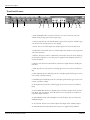
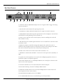
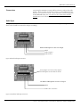
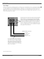
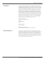
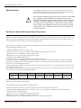
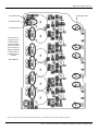
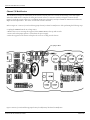
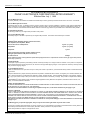
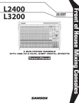
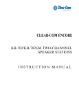
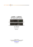
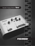
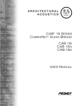
SMRTM821
Stereo Mic/Line
Program Audio Mixer
User Manual
Architectural Acoustics
SMR 821 User Manual
Thank You!
3
What's In The Box?
3
Description
3
Features
4
Front Panel Features
5
Rear Panel Features
6
Installation
7
Connections
Channel Input
8
Stereo Input
9
Master Bus Link
10
Remote Volume and Channel Select
11
Configuration
12
Applications
Restaurant
14
Hotel Meeting Room
15
Presentation Room
16
Bar
17
Small House of Worship
18
Plant Paging
19
Courtroom
20
Frequently Asked Questions (FAQ)
21
Tech Support
22
Warranty Registration
22
Options & Modifications
Microphone Input Transformers
23
Channel 7 & 8 Select Switch Defeat Modification
25
Functional Block Diagram
26
E qualizer Frequency Response Chart
27
Specifications
28
Warranty Statement
31
WARNING! To prevent electrical shock or potential fire hazards, do not expose the SMR 821 to moisture or rain. Before using this product, read the user
manuals for further warnings and cautions.
The following cautions should be carefully observed when installing, wiring or using this product:
DO NOT use any other power supply or cable other than the one provided with this unit.
DO NOT remove the top cover of the SMR 821. There are no user serviceable parts inside. Refer service to qualified personnel.
DO NOT use solvents or other cleaners to clean the unit. Basic external care requires only a damp cloth. Disconnect the power supply cord before cleaning.
Read all safety and installation instructions and retain all documentation for further reference.
Installation of the SMR 821 should such that it’s mounting position does not interfere with proper ventilation.
This product should not be installed or placed near a source of heat.
Power supply cords and associated connectors should be unplugged from the power source when the unit is not used for long periods of time, or will be
stored.
If this product is to be mounted in an equipment rack, install rear support if required by the rack manufacturer.
Care should be taken to ensure that the installation is clear of possible sources of contamination. Make sure that the product’s ventilation openings are not
exposed to possible sources of liquid, gases, or other contaminant.
This product should be inspected by a qualified service technician if the power supply cord or connector has been damaged, if the unit has been dropped, or if
a foreign substance has gained access to the interior electronic and electrical components.
Page 2
http://aa.peavey.com copyright 2000 All Rights Reserved
Welcome
Thank You!
Thank you for purchasing the SMR 821 Mic/Line Program Mixer. This product is designed to provide years of trouble-free operation, and high quality
audio performance. We sincerely hope that you enjoy your new SMR 821,
and will find other products in the Peavey Architectural Acoustics product
line to supplement your new mixer. We are confident that you will find the
SMR 821, as well as other Architectural Acoustics products to be of the
highest quality available.
This manual was written to provide as much information as possible for
your new Peavey Architectural Acoustics product. It is our sincere desire
that you enjoy your purchase. We feel that the best way to fully enjoy any
purchase is to have an in-depth understanding of the product’s features,
functionality and performance characteristics. We hope that this manual,
along with the manuals of our other products will provide this. If you
require additional information that this manual does not provide, please let
us know. We are always looking for better ways to provide information
about our products, and your input is always appreciated. If you have a
comment about this manual, or would like to make a suggestion, please
write to: Peavey Electronics Corp., Architectural Acoustics Division, 711 A
St., Meridian MS, 39301. Thank you again for using Peavey!
What’s In The Box?
The SMR 821 is packaged in a single container. This container includes the
following items:
1- SMR 821 Mic/Line Program Audio Mixer
1- IEC removable power supply line cord
(120VAC Domestic, 230VAC Export)
2- 5-screw Euro connectors*
9- 3-screw Euro connectors*
1- Plastic Security Cover for EQ controls*
1- User Manual/Literature Package
4- Rubber feet
* Asterisk indicates that these items are shipped installed on the SMR 821.
If any of these items are missing, please contact your Authorized Peavey
Architectural Acoustics contractor/dealer.
Description
The SMR 821 is a professional Microphone and Line level audio program
mixer intended for fixed installation applications. This single rack-mount
package is designed to provide high quality audio performance, versatile
control options and simple, easy to use controls. Engineered from the
ground up with the commercial sound systems contractor in mind, the SMR
821 includes removable screw connectors for easy installation and cost effective servicing, as well as limited front panel user control.
With three independent audio output buses, the SMR 821 is perfect for
applications where stereo output and simple monitoring is required. Six of
the eight inputs include high quality microphone pre-amplifiers and separate
gain controls. Additional rear panel controls provide even more flexibility
for proper gain setup, output assign and remote control features.
Peavey Electronics Corp.
Page 3
SMR 821 User Manual
Features
- Single rack space package
- Eight total inputs (6 balanced Mic/Line, 2 un-balanced stereo)
- LED Level/Clip status indicator on each channel
- Mic inputs include selectable 48 volt phantom power
- Two selectable stereo line inputs (mono or stereo switchable)
- Three assignable electronically balanced outputs (Left, Right, Aux)
- Master level controls for each output bus
- Three 5 LED meter arrays
- 4-band EQ (low, low mid, high mid, high)
- Integral Ducking/Muting system
- Audio and mute bus linking
- Left, Right, Aux and Mute bus links for stacking multiple SMR 821’s
- Rear panel Master/Slave linking mode switch
- Remote stereo input select
- Remote Master L/R level control port
- Rear panel 20 dB pad switch on each microphone input
- Front panel continuously variable preamp gain control
- Rear panel bus assign switches for each microphone channel
- Rear panel global 100 Hz low cut filter switch for all mic inputs
- Mute bus with Channel 1 rear panel threshold control
- Select switch for routing microphone mix bus post remote control
- All audio I/O on removable connectors
In stand alone applications, the SMR 821 is a very powerful tool. Ease
of use, external control options and a simple interface make it perfect
for many applications where the end user must have access to the audio
system. The SMR 821’s ability to link multiple units provides even
more flexibility for a wide range of applications. Among the many
applications the SMR 821 was designed for include:
- Presentation Rooms
- Board Rooms
- Courtrooms
- Auditorium/Cafetorium
- Lecture Hall Sound Reinforcement
- Meeting Rooms
- Convention Centers
- Paging
- Background Music
- Retail Spaces
- Restaurant/Bar Sound
The SMR 821 is a prefect choice for many audio applications. This manual will show how some of these applications fit into the SMR 821’s
feature set, and how you can maximize your system designs.
To fully grasp all of the functionality and possible uses of the SMR 821,
please refer to the Applications section later in this manual.
Page 4
http://aa.peavey.com copyright 2000 All Rights Reserved
Panel Features
Front Panel Features
1
2
3
4
5
6
7
8
9
10
11
12
13
14
1. GAIN CONTROL This can also be referred to as a “trim” control. It varies the
amount of mic preamp gain at the first gain stage.
2. STATUS LED This bi-color LED illuminates green when a signal at -20dBm is present, and red when the signal level is near clipping.
3. LEVEL The Level control adjusts the channel signal level sent to the mix buses.
4. CHANNEL 7 & 8 LEVEL The Level control adjusts the channels’ stereo signal level
sent to the mix buses.
5. SELECT The Select switch is a momentary switch that selects the stereo input signal from either Channel 7 or 8. When power is applied to the SMR821, Channel 7 is
selected by default.
6. SELECT LED The Select LEDs indicate which stereo input channel is feeding the
mix buses.
7. LOW EQ The Low EQ control is a shelving type active tone control. (±15 dB at 70
Hz).
8. LOW MID EQ The Low Mid EQ control is a bandpass (peak/notch) type of active
tone control. (±15 dB at 250 Hz).
9. HI MID EQ The Hi Mid EQ control is a bandpass (peak/notch) type of active tone
control. (±15 dB at 3.1 kHz).
10. HI EQ The Hi EQ control is a shelving type of active tone control. (±15 dB at 10
kHz).
11. LEVEL METERS The three 5-segment LED Level Meters monitor the levels of the
Left, Right, and Aux outputs. The 0 dB reference level corresponds to +4 dBu at its
respective output connector.
12. LEFT/RIGHT LEVEL The Left/Right Level control adjusts the level of the Left
and Right outputs.
13. AUX LEVEL The Aux Level control adjusts the output of the Auxiliary output.
14. POWER LED This LED indicates that AC power is applied to the SMR 821.
Peavey Electronics Corp
Page 5
SMR 821 User Manual
Rear Panel Features
12
16
15
14
13
10
9
8
6
11
9
8
7 5
4
3
2 1
1. CHANNEL 1 MUTE THRESHOLD Adjusts the level of signal needed to trigger the muting
circuitry in Channel 1.
2. PAD The Pad switch attenuates the input signal by 20 dB.
3. CHANNELS 1-6 INPUT Balanced microphone or line input on removable connector.
4. ASSIGNMENT SWITCHES Assigns the input channel to the Left, Right, or Aux mix buses
and enables the 48 volt phantom power for channels 1-6.
5. LOW CUT Low Cut filter with a corner frequency of 100 Hz Enabling this switch will
affect Channels 1-6 only.
6. MIC MIX Allows the summed signal of Channels 1-6 to be routed before or after the remote
L/R volume control.
7. RIGHT OUT MUTE Controls the muting of the right mix bus. When this switch is
enabled, the left and right mix buses are affected by the activity of the muting circuit. When
this switch is defeated, only the left bus is affected by the muting circuit.
8. MODE Selects either Stereo mode or Mono mode for Channel 7 or 8.
9. CHANNELS 7 AND 8 INPUT Dual RCA connector for stereo input sources (nominally -10
dBV).
10. EQ Places the 4-band equalizer in or out of the Left and Right signal paths. In the OUT
position the equalizer is completely bypassed.
11. BUS LINK SWITCH For use with multiple SMR 821’s, this switch places the mixer in the
master or slave mode of operation.
12. LEFT OUT, RIGHT OUT, AUX OUT Main mix bus balanced outputs.
13. BUS LINKS “Stacking” connector for multiple SMR 821 mixers.
14. REMOTE CONNECTOR Used to control the Left/Right Master Volume Control and
Stereo Input Select from a remote location.
15. POWER SWITCH Applies power to the SMR821.
16. A/C POWER RECEPTACLE For standard IEC power cable (included).
Page 6
http://aa.peavey.com copyright 2000 All Rights Reserved
Installation
Installation
The SMR 821 is designed to be installed in a standard EIA equipment rack.
Since the depth of the unit is only 8-3/4”, you can use practically any size
rack. Using only a single EIA rack space, the SMR 821 includes integral rack
mounting ears and does not require any additional hardware for rack mounting.......other than the rack screws!
All connections for the SMR 821 are made on the rear panel. It is recommended that you provide an additional 4” of clearance between the rear of
the chassis and the interior rear of your equipment rack for wiring harnesses.
Since every connection to the SMR 821 is easy to disconnect, the unit can be
removed from an equipment rack easily, without have to disturb fixed
wiring harnesses.
Although the SMR 821 does not generate enough heat to warrant forced air
or convection cooling, it is recommended that you provide a single rack
space vent above, and below the unit when rack mounting. Using common
sense when installing this unit will ensure that it will provide years of trouble free service. In installations where there are multiple power amplifiers, it
is further recommended that the SMR 821 be located more toward the top of
the rack, while power amplifiers remain near the bottom. This is generally
considered to be standard rack design in the commercial audio industry.
Following this convention will ensure adequate rack cooling and reliable
operation from the SMR 821.
Peavey Electronics Corp
Page 7
SMR 821 User Manual
Connections
Connecting the SMR 821 is not much different than any other analog audio
product. There are inputs and outputs, but there are also additional connections that you need to be aware of . These include the external control ports
and the Bus Link connectors. All cables for these connections should be
shielded. Refer to the following illustrations for each type of connection.
Audio Input
The inputs to the SMR 821 are balanced. This means that there are three wires for each connection, a positive, negative and
shield. These should be connected to each pin accordingly.
Balanced Microphone or Line Level Input
Shield
Audio Negative
Audio Positive
Figure 1. Balanced Audio Input Connections
Insert jumper wire between the negative
and shield pins for un-balanced circuits.
Un-Balanced Microphone or Line Level Input
Shield
Audio “Hot” or Positive
Figure 2. Un-Balanced Audio Input Connections
Page 8
http://aa.peavey.com copyright 2000 All Rights Reserved
Connections
Stereo Inputs
Channels 7 and 8 provide two individual inputs for each channel. These are intended for stereo use, as each input (Left, Right)
has a fixed assignment to the Left and Right output buses. Additionally, a sum of both inputs is fed simultaneously to the Aux
output bus. Although you cannot change the distribution of these inputs, you can determine if they are stereo or mono. The
Mode Switch, when enabled, will sum both connectors, feeding both to the Left and Right outputs simultaneously. These connectors accept nominal levels of -10dBV.
The Mode switch selects either Stereo mode or Mono mode individually for Channel 7 or 8. In the Stereo mode, the Left input signal
feeds the Left mix bus and the Right input signal feeds the Right
mix bus via the front panel Level Control. In the Mono mode, the
summed Left and Right input signals feed both Left and Right mix
buses. This allows for only one input to be used to feed the stereo
mix buses. Additionally, it allows for Left and Right outputs of the
source to be summed without a Y-cable. In either mode, a summed
mono signal feeds the Aux mix bus.
Unbalanced RCA connections
Left Shield
Left “Hot” Audio
Right Shield
Right “Hot” Audio
The cabling for these connectors should be of
the standard, consumer un-balanced shielded
type. If you are using a 2-conductor shielded
cable, make sure to connect the negative side of
the signal to the shield. NOTE: Unbalanced
signal sources should be located within approximately 6’ of the SMR-821.
Figure 3. RCA Input Connections
Peavey Electronics Corp
Page 9
SMR 821 User Manual
Master Bus Output & Link Connections
These connectors allow you to expand your SMR 821. The Bus Links connector has 5 pins for combining multiple SMR 821’s.
Using a 4-conductor, shielded cable, you can easily connect between 2 or more units wiring pin-to-pin across multiple SMR 821
mixers. NOTE: Use only shielded cable! Refer to the illustrations below.
Audio Bus Outputs, Typical For Each Bus
Master Mixer
Audio Positive
Audio Negative
Shield
In a linked system, the Master mixer’s
outputs would be the primary system
outputs.
The EQ switch places the 4-band equalizer in or out of the
Left and Right signal paths. In the OUT position the equalizer is completely bypassed.
The Bus Link switch is used to place the mixer in the master
or slave mode of operation. A stand-alone unit should
always be in the master mode.
Master Bus & Mute Link Connections
Left Audio Link (L)
Right Audio Link (R)
Link Shield (SHD)
Aux Audio Link (A)
Mute Bus Link (M)
Slave Mixer 1
To increase the number of inputs available, multiple mixers may
be linked together. Linking mixers is a very simple process. Wire
the Bus Links connections between each mixer. Select the mixer
to be used as the master and place its Bus Link Switch in the
MASTER position. All other mixers in the system should have
their link switches in the SLAVE position. The EQ and master
level controls of the unit chosen as MASTER should be used to
control the system. NOTE: Slave mixer outputs are still active,
and will output any channels assigned to them.
Slave Mixer 2
Figure 4. Master Output & Bus Link Connections
Page 10
http://aa.peavey.com copyright 2000 All Rights Reserved
Connections
External Control Connections
The SMR 821 provides a powerful external control option. This feature allows you to configure remote controls for the Master
Left/Right volume and the Channel 7/8 select function. The Remote connector provides a simple way to make these connections. NOTE: Use only shielded cable! Refer to the illustrations below.
This example is used to control the Left/Right Master Volume
Control from a remote location with a simple connection on the
back of the unit. A 10k pot will provide approximately 0 to 30dB of
attenuation. A 100k pot will provide about 0 to 60dB of attenuation. If desired, a control voltage can be inserted to “command”
attenuation instead of a pot. This voltage is inserted into the “C”
input and is positive referenced to SHD. NOTE: THE CONTROL
VOLTAGE SHOULD NEVER EXCEED 11 VOLTS DC.
Remote Volume Control Connections
Volume Control to Potentiometer CW Leg (V)
Control to Potentiometer Wiper Leg (C)
Shield Potentiometer CCW Leg (SHD)
Remote
Volume
Figure 5. Remote Volume Control Connections
This example shows the connection for remote selection of the
Channels 7 or 8 input select feature. The selection is done by connecting a momentary switch between SEL and SHD. Each time
the switch is actuated, the channel selection is toggled and alternated between Channel 7 and 8. This remote operation functions
in conjunction with the front panel Select Control. A bi-color
LED or 2 individual LEDs may be connected as shown in the
diagram for remote indication of the selected stereo line input.
NOTE: The IND circuit can supply a maximum of 6ma for the
LEDs’. Take care that you do not exceed this current limitation.
Remote Channel 7/8 Select Connections
Shield (SHD)
Channel 7/8 Select (SEL)
Indicator LED Output (IND)
Ch 7-8
Select
Switch
Ch 7-8
Select LEDs
Ch 8
Ch 7
Figure 6. Remote Channel 7/8 Select Connections
Peavey Electronics Corp
Page 11
SMR 821 User Manual
Configuration
Since the SMR 821 is an analog product, there is not a lot of configuration to worry about. No software, no data cables,
no networks and no headaches. However, there are a few things to remember while you begin to use your new SMR
821 mixer.
The SMR 821 is shipped from the factory ready to go. You should be able to follow the steps below, and get audio
through the unit.
The first step is to calibrate your gain settings for the inputs. Each microphone input
has a Gain Control and a Level Control. These controls work together, while the
Status LED and the master Level Meters provide a visual indication of the control’s
behavior. To properly adjust the SMR 821 for optimal performance, follow these simple
steps for each input channel:
1. Adjust the Channel, Master L/R and Aux Level Controls so they are at the midpoint.
There is a “center detent” on the control which indicates this position.
Figure 7. Input Channel Controls
2. Adjust the channel Gain Control to its minimum position, or fully counter-clockwise
for the channel you are working on.
3. Apply an audio signal to the input by either playing a line level audio source
or by speaking into a microphone at a nominal level. While monitoring the
master Level Meters, slowly adjust the Gain Control clockwise while audio is
present. Keep turning the control until the Level Meters are indicating nominal level around the -6 to 0dB area on the meters. In addition, the channel
Status LED should be green and not red. The bi-color Status LED illuminates
green when a signal is present at -20 dBu. It illuminates red when the signal
level is near clipping. The Level Control adjusts the signal level sent to the mix
buses. This control should be operated near the mid-point of its travel to assure
Figure 8. Master Meters and Controls
an optimized signal-to-noise ratio and maximum headroom, once the Gain
Control is set correctly. If you find that the input signal is too hot, and you
cannot properly adjust the gain control without causing a clipping condition, you will need to use the Pad Switch,
located on the rear panel. This switch will give you an additional 20dB of pad beyond what the front panel Gain
Control provides. Follow this procedure for each input to ensure proper gain structure.
For channels 7 and 8, there is no gain control. To properly adust the gain on
these channels, you will need to control the output level of the audio source.
With the Channel Level and the Master Level controls at the detent position,
a -10dBV signal will present a +4dBu output at the Bus Output connectors.
Figure 9. Master Meters and Controls
It is important to adjust the gain DOWN enough so the preamp will not clip at
louder levels. Carefully consider the type of audio source, and adjust the gain
settings accordingly. Material with wide dynamic range will generally require
a lower Gain Control setting, while material that is fairly constant, can usually tolerate a higher setting.
After these adjustments are made, make sure you monitor the front panel LED’s
and meters during normal use. Take note of the action of the Status LED’s. Under normal operation, you should see
lots of green, but it is not unusual to see occasional flashes of red. Constant red, however, indicates that a gain setting
is improperly adjusted, and should be re-set using the above procedure.
Page 12
http://aa.peavey.com copyright 2000 All Rights Reserved
Configuration
The next step is to configure the SMR 821’s many rear panel switches for your application. Although the unit is
shipped from the factory with default switch values, you should make sure that these settings are correct for YOUR
application. Let’s take a look at each one, and describe their functionality.
First, there are the Channels 1-6 Bus Assign Switches. These switches provide
the ability to assign each input to the Left, Right or Aux output buses. In addition, you can turn on or off the phantom power on each channel. There is a single
8-position DIP switch for each TWO input channels. Take care that you are
adjusting the correct switch for the correct channel. It is recommended that you
use a small screwdriver or other instrument to set the switches. Do not force
them. Also, keep in mind that the ON position is on top. Figure 10 shows the DIP
switches with all functions in the ON position. NOTE: The factory setting is all
bus assign switches ON, and phantom OFF.
Figure 10. Input Channel Bus Assign
About the middle of the rear panel, you will find a
Switches and Input Connectors
group of three switches. They include the Mic Mix
switch, the Rt Out Mute switch and the Low Cut switch. The Mic Mix switch allows
the summed signal of Channels 1-6 to be routed before or after the remote L/R volume control. In the “Pre Remote” position, the signals from Channels 1-6 are affected by the remote
volume control along with the stereo input from the either Channel 7 or 8. In the Post
Remote position, only the stereo input from either Channel 7 or 8 is affected by the remote
volume control. The factory default setting is “Pre-Remote”.
Figure 11. Mic Mix, Rt Out Mute The Rt Out Mute switch controls the muting of the right mix bus. The factory setting of
this switch is “Enable”. When enabled, the left and right mix buses are affected by the
and Low Cut Switches
activity of the Channel 1 muting circuit. When this switch is defeated, only the left bus is
affected by the muting circuit. Use the Channel 1 Mute Threshold control to set the trigger point to activate the muting.
The Low Cut Switch enables a filter with a corner frequency of 100 Hz and is helpful to filter out rumble, wind noise,
breath thumps, and other low-frequency signals that rob amplifier power and muddy the mix. Enabling this switch
will affect Channels 1-6 only. The factory default setting for the Low Cut switch is “Defeat” or “Flat”.
The Mode switch selects either Stereo mode or Mono mode for Channel 7 or 8. In
the Stereo mode, the Left input signal feeds the Left mix bus and the Right input
signal feeds the Right mix bus via the front panel Level control. In the Mono mode,
the summed Left and Right input signals feed both Left and Right mix buses. This
allows for a mono source to be used to feed the stereo mix buses. Additionally, it
allows for Left and Right outputs of the source to be summed without a Y-cable. In
either mode, a summed mono signal feeds the Aux mix bus. The factory default is
“Stereo”.
The EQ switch places the 4-band stereo equalizer in or out of the Left and Right signal paths. In the OUT position the equalizer is
Figure 12. Channel 7 & 9 Mode Switches
completely bypassed. The factory default is IN.
The Bus Link switch is used to place the mixer in the master or slave mode of operation. A stand-alone unit should always be in the master mode, and the factory
default is MASTER. See the “Connections” section of this manual for details on Bus
Linking and using multiple SMR 821’s.
Figure 13. Channel 7 & 9 Mode Switches
Peavey Electronics Corp
That’s about it for configuration. As you can see, the SMR 821 provides many powerful features for better, more cost effective systems. The multiple combinations of
routing, control and input assignment facilitate a wide range of applications.
Page 13
SMR 821 User Manual
Restaurant
You’ve seen them...you know, the trendy restaurants at major off-ramps of every interstate in the country. Good
atmosphere, OK food, high prices, young staff and a sports-oriented bar. This is a great market for sound system work,
since all of these places have multiple zones of audio, video distribution and paging. The SMR 821 is perfect for these
applications and provides a very simple interface for the end user. Take a look....
Manager’s Page
Bar Page
Hostess Page
Right Bus
Aux Bus
All Buses
Satellite Receiver
Left
Lobby Zone
Main Seating Area
Right
Bar Seating
Patio Seating
Aux
System Features:
- Two independent music feeds. The L/R outputs are further split into two separate zones.
- Hostess paging “ducks” music source using the Channel 1
threshold feature. This is normally used for the “your table
is ready!” page.
- Remote control of volume at the hostess podium.
- Remote control of music source at the manager’s office.
This source select switch could be placed at multiple locations by paralleling.
- Each microphone is assigned independently. The Hostess
mic feeds all zones, the manager’s mic feeds only the Main
Seating area and the bar mic feeds only the bar and the
patio zones.
Page 14
Manager’s Music Source
Office Select Panel
Hostess
Podium
Master
Volume
Control Panel
http://aa.peavey.com copyright 2000 All Rights Reserved
Applications
Hotel Meeting Rooms
The SMR 821 is a very powerful product for use in meeting rooms. The use of the Bus Link feature provides the ability
to combine, separate or control multiple units. In this example, we shall see how multiple SMR 821’s can be used
effectively for meeting room applications.
Emergency Page Source
In Room Control
Music On/Off
Master Volume
In-Room Mics
Main Music Source (BGM)
(Master)
Room A
Power Amplifier
Room Combine
A&B
In Room Control
Music On/Off
Master Volume
Room B
Power Amplifier
Room Combine
B&C
In Room Control
Music On/Off
Master Volume
Room C
Power Amplifier
System Features:
- Shown as a 3-Room System, this configuration could allow for larger combinations.
- Each room has it’s own local inputs and outputs, independent of the others. In addition, there is a wall mounted control panel
in each room with a music ON/OFF switch and Master Volume control. These are wired to the remote control ports on the
SMR 821’s Remote Connector.
- A Room Combine panel allows linking of adjacent rooms, or all three rooms. These are simple switches wired between the
SMR 821’s Bus Link ports. In this example, we are linking the main audio and the mute bus.
- The “house” BGM audio is fed to all three rooms. The music ON/OFF control is actually the Channel 7/8 Remote Select, but
since there is no music on Channel 7, the switch acts as an OFF control.
- The emergency page audio is wired to each mixer’s Channel 1 input. When a page is active, all music will mute, and the page
will be allowed to go through. Since this page source is paralleled across all of the Channel 1 inputs, it has priority over all
other inputs, and is independent of the Room Combine mode.
This system could be configured many different ways. For example, you could use the Channel 7 input in each room for a local
music source and determine if the remote control “mutes” or “selects” the music. The Room Combine panels could be located at
the equipment rack to prevent un-authorized tampering, or in the hallways for banquet personnel to adjust.
Peavey Electronics Corp
Page 15
SMR 821 User Manual
Presentation Room
What exactly is a “Presentation Room” anyway? Well, it could be many things. It could be a small board room in a
corporate environment, or a large theatre-style classroom in a major university. Or, it could be a folding table in your
shop, used to present new ideas to your installation crew. Basically, any place that ideas or information can be presented to a group of people could be classified as a “Presentation Room”. In this example, we will assume that our
Presentation Room has a sound system, video display system and a means to control these systems centrally or by
remote control.
Audio From
Video
C
R
Left
Control
System
Right
L
Aux
Stereo
Loudspeakers
Center
Loudspeaker
System Features:
- Microphone Inputs for speech reinforcement on channels 1, 2 and 3 assigned to the Aux Bus only.
- Inputs for audio from video switcher. Left, Center and Right audio channels connected to channels 4, 5 and 6, assigned to Left,
Center and Aux output buses respectively. This will provide for 3-channel playback with dialog on the center (AUX) bus and
the music bed on the stereo (LEFT, RIGHT) bus.
- Stereo tape playback on Channel 7 distributed to Left, Right and Center channels.
- Stereo CD playback on Channel 8 distributed to Left, Right and Center channels.
- Interface with control system with dry contact, resistance and voltage control for Tape/CD select and overall volume control.
- Outputs for 3 channels of audio. Left/Right and Aux. The Aux bus provides the audio for the center channel.
The Control System in this example is typical of many popular software based systems. The control circuit that is connected to
the SMR-821 would be a dry contact or variable resistance type of connection. Typically, the source controls, in this case the
CD player and the tape deck, would be infrared control connections.
Page 16
http://aa.peavey.com copyright 2000 All Rights Reserved
Applications
Bar
Yeah, you know. A bar...or “club”. This example assumes a small bar with live music, but not a full blown stage with
lights and huge flying loudspeaker arrays, etc. Basically, this is the type of bar where you go to get some food, have
some adult beverages and kick back. The music is low-key, usually a small acoustic guitar-vocal group or a solo
singer-songwriter. You need to be able to reinforce the live inputs, provide control for the background music, allow
for simple paging and give the bar manager a “turn it down” knob. You can do this and more with the SMR 821.
Live
Music
Mics
Page
Mic
Bar Manager’s
Master Volume
Control
Hostess
BGM Mute
Control
Stereo Live Music
Loudspeakers
Left
Right
Patio, Rear Bar &
Restroom
Loudspeakers
Aux
System Features:
- Separate loudspeaker systems for the live music area and the rest of the facility.
- Background music source is defeatable by remote switch at hostess podium or cash register. Additionally, this control can be
located at the stage area as well, so the performer can mute the BGM when the live performance begins.
- Live mics are routed throughout the bar, but at separate levels for areas not in the direct vicinity of the performer are under
separate volume control.
- Master volume control is under the control of the Bar Manager.
Peavey Electronics Corp
Page 17
SMR 821 User Manual
Small House of Worship
For small churches, synagogues or similar houses of worship, the SMR 821 is a perfect choice. A very simple interface,
high quality audio performance and multiple outputs make it ideal. Similar products in this price range may be well
suited for paging or background music, but generally do not have the audio quality required for speech presentation or
live musical performance.
Pastor
Altar
Choir
Choir
Vocal
Piano
Usher’s Control Panel
Master Volume
Music Mute
Main Cluster
Left
Right
Nursery, Foyer
Hallways, Restrooms
Aux
Choir Monitor
System Features:
- Independent audio feeds for the Sanctuary and the Nursery, Foyer, Hallways and Restrooms.
- Aux feed with separate level control for the choir.
- Remote Control of master volume and music mute via wall mounted panel in the foyer.
- Six microphone inputs are plenty for a small facility.
- High quality audio performance.
- Simple, easy to use front panel and remote controls eliminate the need for a console.
- Low cost installation.
Page 18
http://aa.peavey.com copyright 2000 All Rights Reserved
Applications
Plant Paging
For large scale paging applications, the SMR 821 is a cost effective option to digital systems. By using multiple units
and “busing” common inputs, you can create multiple zone systems. In this example, each area of this facility has it’s
own local paging and music audio. A common “All Call” mic is fed to each zone’s Channel 1 input.
Office
All Call
Shop Floor
Supervisor
Office
Manager
Local Music
ZONE 1 - Assembly Plant
NOTE: When busing audio
inputs across long distances, it is recommended
that the optional
Microphone Input
Transformer accessory be
installed. See the Options
& Modifications section
later in this manual for
installation instructions.
Shop Floor
Administrative Offices
Loading
Dock
Picking
Clerk
Local Music
ZONE 2- Warehouse
Loading Docks
Inventory Locations
To Other Locations
System Features
- Independent paging and music audio for each zone.
- All call paging distributed to all zones mutes or “ducks” the local music source and local paging mics.
- Independent outputs for each area allow for different volume settings.
- Remote control option provides the ability to create a master volume and music mute control.
Peavey Electronics Corp
Page 19
SMR 821 User Manual
Courtroom
In this example, we need more than 6 microphones for this courtroom project. Using the SMR 821’s Bus Link feature,
we can easily create a 12x2 mixer. The Master mixer feeds the power amplifiers and the logging recorder. Using the
Aux output for the logging recorder provides a separate volume control, and channel assignment. In some cases, you
may not want every microphone to log to tape. Keeping the recorder feed separate provides this functionality.
Witness
Judge Judy
Jury Foreman
Court Reporter
Portable
Clerk
Master
Volume
Slave
Defense Attorney 1
Prosecution 1
Defense Attorney 2
Prosecution 2
Prosecution Aux
Defense Aux
Bus Link
Master
Main Courtroom
Spectator Area
Logging Recorder
System Features
- 12 microphone inputs.
- Separate feeds for main speakers, spectator speakers and tape recorder.
- Bus Link feature provides seamless combining of two mixers.
Page 20
http://aa.peavey.com copyright 2000 All Rights Reserved
FAQ
Frequently Asked Questions
I just hooked up my new SMR 821, and I can’t get audio from any of the outputs.
A common cause for this is the Bus Assign switches not being assigned to any of the outputs. Make sure that the input you are
using is assigned to the output bus that you have your amplifier connected to.
When I adjust the equalizer controls on the front panel, nothing happens.
Check the rear panel EQ switch. If this switch is in the OUT position, the front panel EQ is defeated.
I want to feed 2 mono music sources independently to the Left and Right outputs. How can I do this?
You can actually connect 4 mono sources, two for each output (Left, Right). By configuring the Channel 7 and 8 MODE switches to MONO, you can create dual 2x1 switchers. Each of the Left inputs will feed the Left output, depending on the position of
the front panel Channel 7/8 select switch. The same applies to the Right inputs.
I am using the Left and Right outputs in mono for music and paging in a 2-zone configuration. However, I want one
zone to be independent of the Channel 1 muting feature. How can I do this, and still keep the other zone’s muting
feature active?
By default, the SMR 821’s muting feature is active on both the Left and Right outputs. However, you can disable this feature for
the Right channel by enabling the rear panel RT OUT MUTE switch. Also, the AUX output is not affected by the action of the
Channel 1 mute feature.
When I connect my high quality condenser microphone, I cannot get any indication that the mic is working. I have
confirmed that the gain structure and output assign functions are properly set. What is going on?
Most condenser microphones require an external phantom power source to operate. Activate the phantom power for the
microphone input channel where your condenser microphone is connected. This phantom power switch is located in the BUS
ASSIGN switch bank for each channel. To activate phantom power, turn down all Level Controls and then place this switch in
the ON position.
I have a paging microphone connected to Channel 1 and a music source on Channel 7. I want the music to mute
whenever a page is made, but it doesn’t seem to work. What am I doing wrong?
Most likely, you do not have the Channel 1 MUTE THRESHOLD control adjusted properly. This control has to be adjusted so
that when a nominal level is present at the microphone, the music will mute. Care should be taken in this adjustment however,
because a setting that is too low will require an excessive level at the microphone to activate the mute function. A setting that
is too high could inadvertently mute ambient sounds near the microphone location.
I would like to build a remote control panel for volume control. Can I connect a remote potentiometer for each
channel?
No. Only the Master Volume control is capable of external control.
I would like to link multiple mixers. If I do this, can I still use the main outputs from each mixer?
Yes. In a linked configuration, the MASTER mixer’s outputs include audio from ALL mixers in the link. However, the outputs
of the Slave mixers are still active, and can be used to feed “local” circuits.
I have a CD player connected to Channel 2, instead of the stereo inputs. The sound quality is very poor. Why?
Check your wiring. Channel 2 is a single balanced input, and most CD players have dual un-balanced outputs. In this configuration, you will need either sum the two CD outputs to a single output, or use just one of the outputs. In addition, you will
need to add a jumper between the negative and shield terminals. Also, make sure you use the PAD switch to prevent overloading. (See the “Connections” section of this manual for details).
The sound system where my SMR 821 is installed needs to be on 24 hours a day. Is this OK?
Yes. The SMR 821 is designed to operated continuously.
Peavey Electronics Corp
Page 21
SMR 821 User Manual
Tech Support
Peavey has an extensive Technical Services Group that provides tech support, repair and implementation services. If you require assistance with your
new SMR821, you can get help from several sources. There are many technical documents, white papers and application notes on our website as well as
brochures, data sheets and our newsletter, “Audio Interactive”, published
monthly. Also on our website are message board forums that include questions and answers on all audio topics. This forum is a great way to learn
more about audio, Peavey products and system design from other audio professionals around the world. You can also get help by sending us an e-mail
or posting a request on the message board. Finally, if you still cannot get the
information you need, don’t hesitate to call us. We have extensive phone
support services and will be happy to assist you. The contact information
for the Architectural Acoustics Division is shown below:
Peavey Electronics Corp.
Architectural Acoustics Division
711 “A” St.
Meridian MS 39301
USA
Phone: 601-483-5376
Fax: 601-486-1678
Website: http://aa.peavey.com
Email: [email protected] (Technical Services Manager)
Warranty Registration
Page 22
Please take a few minutes and fill out the warranty registration card for
your SMR 821. Although your warranty is valid without the registration, the
information you provide with the form is crucial to our support group. It
enables us to provide better service and customer support, and to keep you
informed of new product updates, and software revisions. Refer to the warranty statement on the back page of this manual for details about what your
warranty includes and what the limitations are.
http://aa.peavey.com copyright 2000 All Rights Reserved
Options & Modifications
Optional Features
The SMR 821 offers optional features for specific job requirements. These
options include Transformers for the microphone inputs and the ability to
defeat the functionality of the Channel 7/8 select switch.
!
These options and modifications require access to the inside of the SMR
821. It is highly recommended that the installation of the optional
microphone transformers and the modification of the Channel 7/8 select
switch be performed by qualified service personnel. There are dangerous voltages present inside the unit, as well as static sensitive components. Damage to the SMR 821’s internal circuitry caused by un-qualified persons is not covered under warranty, and in fact, could void the
warranty altogether.
Installing the Optional Microphone Input Transformers
Optional transformers for use with the microphone input circuits are available from Peavey Electronics Corp. (part #
70500852). The optional transformers may be added one at a time, all at once, or in any combination. To ensure that the transformers are properly installed, please refer to the instructions and illustrations in this section. If you have ANY questions, or
are not sure about it, do not hesitate to call our Tech Support Group.
Refer to Figure 14. “Cutaway of circuit board showing jumper locations for installation of optional microphone transformers”
while performing the following steps:
1. Unplug the SMR821 from the AC voltage source.
2. Remove the 6 screws securing the top panel of the SMR821. Remove the top and set aside.
3. Remove the 5 screws securing the rear panel to the chassis.
4. Remove the 5 screws securing the front panel to the chassis.
5. Carefully turn the SMR821 upside down.
6. Remove the 11 screws securing the circuit board assembly to the chassis.
7. Carefully turn the entire SMR821 right side up. One end of the circuit board assembly (with the front and rear panels still
attached) can be lifted out of the chassis with power supply wires still intact to access the bottom side of the circuit board.
8. Locate the six round transformer outlines.
9. Before installing the transformers, you will need to cut some jumpers and resistors. These components are labeled with reference designators on the board.
10. For each transformer installed, three jumpers and one resistor will need to be cut. The following table shows which components need to be cut for their corresponding transformer.
Transformer
Components
to be cut
T101
J102, J103,
J105, R116
T1201
J202, J203,
J205, R216
T301
J302, J303,
J305, R316
T401
J402, J403,
J405, R416
T501
J502, J503,
J505, R516
T601
J602, J603,
J605, R616
11. The transformers can only be inserted into the board one way. Place a transformer into the circuit board and solder in place.
Repeat for each transformer being installed.
Re-installing the Circuit Board and Re-assembling the Unit
1. Place the circuit board assembly (with the front and rear panels still attached) into the chassis.
2. Carefully turn the SMR821 upside down and replace the 11 screws securing the circuit board assembly to the chassis.
3. Carefully turn the unit right side up.
4. Replace the 5 screws securing the front panel to the chassis.
5. Replace the 5 screws securing the rear panel to the chassis.
6. Place the top panel on the chassis and replace the 6 screws securing it to the chassis.
Peavey Electronics Corp
Page 23
SMR 821 User Manual
Cut Jumper Here
Cut Jumper Here
Cut Resistor Here
Cut Jumper Here
NOTE: Cuts are
typical for each
channel where
the transformers
will be installed.
Do not cut these
jumpers UNLESS
a transformer is
installed for that
channel!
BE CAREFUL!
Figure 14. Cutaway of circuit board showing jumper locations for installation of optional microphone transformers
Page 24
http://aa.peavey.com copyright 2000 All Rights Reserved
Options & Modifications
Channel 7/8 Modification
This modification changes the functionality of the Channel 7/8 front panel select switch and the busing of the audio inputs.
When this modification is complete, the front panel switch will act as a “MUTE” switch for all signals connected to the
Channel 7 and 8 RCA input connectors. In addition, BOTH stereo channels (7 and 8) will SIMULTANEOUSLY feed the Left,
Right and Aux output buses. The “Select” action of the switch is defeated.
Refer to Figure 15. “ Cutaway of circuit board showing jumper location for Channel 7/8 Modification” while performing the following steps:
1. Unplug the SMR821 from the AC voltage source.
2. Remove the 6 screws securing the top panel of the SMR821. Remove the top and set aside.
3. Locate and cut the jumper J905. It is located near the power supply.
4. Place the top panel on the chassis and replace the 6 screws securing it to the chassis.
Cut Jumper Here
Figure 15. Cutaway of circuit board showing jumper location for modification of the Channel 7/8 Modification
Peavey Electronics Corp
Page 25
SMR 821 User Manual
Figure 16. SMR 821 Functional Block Diagram
Page 26
http://aa.peavey.com copyright 2000 All Rights Reserved
Specifications
d
B
r
+20
+18
+16
+14
+12
+10
+8
+6
+4
+2
-0
-2
-4
-6
-8
-10
-12
50
SMR 821
100
200
Hz
1k
2k
STEREO MIC/LINE PROGRAM MIXER
500
5k
10k
20k
Page 27
Peavey Electronics Corp
-14
-16
-18
-20
20
4-Band Equalizer
0 dBr = +4 dBu
Figure 17. SMR 821 Equalizer Response Plot
SMR 821 User Manual
Specifications
MECHANICAL
Dimensions (H x W x D)
1.75" x 19" x 8.75" (45 mm x 483 mm x 222 mm)
Weight
7.4 lbs.
Mounting
Single EIA Space Rack Mount
Connections
Removable “Euro” Connectors for single channel audio inputs, outputs, bus link and
external control. RCA single-ended female for Channels 7 and 8 stereo inputs. IEC
receptacle for AC power.
PERFORMANCE
Test Conditions
120Vac 60Hz maintained throughout testing.
Input Sensitivity
Input
Input
Impedance
(Ohms)
Microphone
without pad
2k
Microphone
with pad
2k
Microphone
without pad
(optional
transformer)
Microphone
with pad
(optional
transformer)
Stereo Line
2k
2k
10k
Input gainpot setting
Max gain
+60 dB
Min gain
+10 dB
Max gain
+40 dB
Min gain
–10 dB
Max gain
+60 dB
Min gain
+20 dB
Max gain
+40 dB
Min gain
0 dB
N/A
Input Level, dBu
Min.*
Nom.**
Max.
–76dBu
–56dBu
–39dBu
–25dBu
–4dBu
+13dBu
–56dBu
–36dBu
–19dBu
–5dBu
+16dBu
+33dBu
–74dBu
–54dBu
–37dBu
–34dBu
–14dBu
+3dBu
–54dBu
–34dBu
–17dBu
–14dBu
+6dBu
+23dBu
–20dBV
–10dBV
+7dBV
Balanced/
Unbalanced
Connector
Balanced
+
–
Ground
Balanced
+
–
Ground
Balanced
+
–
Ground
Balanced
+
–
Ground
Unbalanced
RCA jacks
0 dBu = 0.775 Vrms
0 dBV = 1.00 Vrms
*
Min. input level (sensitivity) is the smallest signal that will produce a nominal output with controls set at maximum gain.
**
Nominal settings are defined as all controls set at center detent for nominal
output. Microphone gain control is as specified.
Page 28
http://aa.peavey.com copyright 2000 All Rights Reserved
Specifications
Output Specifications
Output
Output Level
Min Load
Impedance
Nom
Max
Balanced/
Unbalanced
Left/Right
600 ohms
+4dBu
+21dBu
+19dBm
Balanced
Aux
600 ohms
+4dBu
+21dBu
+19dBm
Balanced
Connector
+
–
Ground
+
–
Ground
0 dBu = 0.775 Vrms
0 dBm = 1 mW
Noise
Output
Left/Right
Aux
Signal/Noise (typical)
100 dB
Test Conditions
All Level controls down
84 dB
Master Level control nominal
Channel Level controls down
80 dB
All controls nominal
All channels assigned
Mic gain minimum
All Level controls down
95 dB
92 dB
Master Level control nominal
Channel Level controls down
81 dB
All controls nominal
All channels assigned
Mic gain minimum
Gain
Mic Input Range without pad:
10dB to 60dB
Mic Input to Output without pad:
80dB max
Mic Input Range with pad:
-10dB to 40dB
Mic Input to Output with pad:
60dB max
Mic Input Range without pad
(optional transformer):
Mic Input to Output without
pad (optional transformer):
20 dB to 60 dB
Mic Input Range with pad
(optional transformer):
Mic Input to Output with pad
(optional transformer):
0 dB to 40 dB
Peavey Electronics Corp
80dB max
60dB max
Page 29
SMR 821 User Manual
Frequency Response
20Hz - 20kHz +0dB/-1dB
Total Harmonic Distortion
Plus Noise
<0.1% typical 20Hz - 20kHz; Mic to L-R out (22Hz - 22kHz BW)
Equivalent Input Noise (EIN)
-128dBu Mic input terminated with 150 ohms
Common Mode Rejection
Ratio (Mic Input)
>70dB typical 20Hz - 20kHz
Crosstalk
Adjacent Channels (1kHz)
>70dB typical
Crosstalk
Output to Output (1kHz)
>60dB typical
Phantom Power
+48 Volts at mic + and - inputs
Remote Volume Control
30dB attenuation (10k ohm potentiometer ) Typical
60dB attenuation (100k ohm potentiometer) Typical
Channel Mute
>60dB attenuation
Signal/Clip Indicators
Input Channel Status
Green: -20dBu
Red:
2dB below clipping
Output Level Meters
-24:
-20dBu
-6:
-2dBu
0:
+4dBu
+6:
+10dBu
Clip:
2dB below clipping
Power Requirements
Page 30
Domestic: 120Vac, 60Hz 15 Watts nominal
Export: 230Vac, 50/60Hz 15 Watts nominal
http://aa.peavey.com copyright 2000 All Rights Reserved
Warranty Statement
Architectural Acoustics®
PEAVEY ELECTRONICS CORPORATION LIMITED WARRANTY
Effective Date: July 1, 1998
What This Warranty Covers
Your Peavey Warranty covers defects in material and workmanship in Peavey products purchased and serviced in the U.S.A. and Canada.
What This Warranty Does Not Cover
The Warranty does not cover: (1) damage caused by accident, misuse, abuse, improper installation or operation, rental, product modification or
neglect; (2) damage occurring during shipment; (3) damage caused by repair or service performed by persons not authorized by Peavey; (4)
products on which the serial number has been altered, defaced or removed; (5) products not purchased from an Authorized Peavey Dealer.
Who This Warranty Protects
This Warranty protects only the original retail purchaser of the product.
How Long This Warranty Lasts
The Warranty begins on the date of purchase by the original retail purchaser. The duration of the Warranty is as follows:
Product Category
Duration
MediaMatrix® DPU, (Excluding Frames), Cinema Processors,
Power Amplifiers, Pre-Amplifiers, Mixers,
Electronic Crossovers and Equalizers
2 years *(+ 3 years)
Loudspeakers
3 years *(+ 2 years)
Microphones
2 years
Speaker Components (including speakers, baskets, drivers,
diaphragm replacement kits and passive crossovers)
and all Accessories
90 days
[*denotes additional warranty period applicable if optional Warranty Registration Card is completed and returned to Peavey by original retail purchaser
within 90 days of purchase.]
What Peavey Will Do
We will repair or replace (at Peavey's discretion) products covered by warranty at no charge for labor or materials. If the product or component
must be shipped to Peavey for warranty service, the consumer must pay initial shipping charges. If the repairs are covered by warranty, Peavey
will pay the return shipping charges.
How To Get Warranty Service
(1) Take the defective item and your sales receipt or other proof of date of purchase to your Authorized Peavey Dealer or Authorized Peavey
Service Center.
OR
(2) Ship the defective item, prepaid, to Peavey Electronics Corporation, International Service Center, 412 Highway 11 & 80 East, Meridian, MS
39301 or Peavey Canada Ltd., 95 Shields Court, Markham, Ontario, Canada L3R 9T5. Include a detailed description of the problem, together
with a copy of your sales receipt or other proof of date of purchase as evidence of warranty coverage. Also provide a complete return address.
OR
(3) All MediaMatrix® Frames needing repair, should be shipped prepaid to Peavey Electronics Corporation, International Service Center, 412
Highway 11 & 80 East, Meridian, MS 39301
Limitation of Implied Warranties
ANY IMPLIED WARRANTIES, INCLUDING WARRANTIES OF MERCHANTABILITY AND FITNESS FOR A PARTICULAR PURPOSE, ARE LIMITED IN DURATION TO THE LENGTH OF THIS WARRANTY.
Some states do not allow limitations on how long an implied warranty lasts, so the above limitation may not apply to you.
Exclusions of Damages
PEAVEY'S LIABILITY FOR ANY DEFECTIVE PRODUCT IS LIMITED TO THE REPAIR OR REPLACEMENT OF THE PRODUCT, AT PEAVEY'S
OPTION. IF WE ELECT TO REPLACE THE PRODUCT, THE REPLACEMENT MAY BE A RECONDITIONED UNIT. PEAVEY SHALL NOT BE
LIABLE FOR DAMAGES BASED ON INCONVENIENCE, LOSS OF USE, LOST PROFITS, LOST SAVINGS, DAMAGE TO ANY OTHER
EQUIPMENT OR OTHER ITEMS AT THE SITE OF USE, OR ANY OTHER DAMAGES WHETHER INCIDENTAL, CONSEQUENTIAL OR OTHERWISE, EVEN IF PEAVEY HAS BEEN ADVISED OF THE POSSIBILITY OF SUCH DAMAGES.
Some states do not allow the exclusion or limitation of incidental or consequential damages, so the above limitation or exclusion may
not apply to you.
This Warranty gives you specific legal rights, and you may also have other rights which vary from state to state.
If you have any questions about this warranty or service received or if you need assistance in locating an Authorized Service Center, please contact the Peavey International Service Center at (601) 483-5365 / Peavey Canada Ltd. at (905) 475-2578.
Features and specifications subject to change without notice.
Peavey Electronics Corp
Page 31
Features and Specifications subject to change without notice.
A product of Peavey Electronics Corporation
711 A Street / Meridian, MS 39301 / USA / (601) 483-5376 / FAX (601) 486-1678
http://aa.peavey.com
Copyright 2000 All Rights Reserved
80304714
Printed in USA 4/2000