1
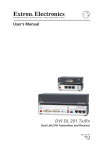
User’s Guide
FOX 2G Tx/Rx AV
Video and Audio Fiber Optic Transmitter and Receiver
68-1466-01
Rev. A
10 08
Precautions
Safety Instructions • English
This symbol is intended to alert the user of important
operating and maintenance (servicing) instructions in
the literature provided with the equipment.
This symbol is intended to alert the user of the
presence of uninsulated dangerous voltage within
the product’s enclosure that may present a risk of
electric shock.
Caution
Read Instructions • Read and understand all safety and operating
instructions before using the equipment.
Retain Instructions • The safety instructions should be kept for future
reference.
Follow Warnings • Follow all warnings and instructions marked on the
equipment or in the user information.
Avoid Attachments • Do not use tools or attachments that are not
recommended by the equipment manufacturer because they may be
hazardous.
Consignes de Sécurité • Français
Ce symbole sert à avertir l’utilisateur que la
documentation fournie avec le matériel contient des
instructions importantes concernant l’exploitation et
la maintenance (réparation).
Ce symbole sert à avertir l’utilisateur de la présence
dans le boîtier de l’appareil de tensions dangereuses
non isolées posant des risques d’électrocution.
Attention
Lire les instructions• Prendre connaissance de toutes les consignes de
sécurité et d’exploitation avant d’utiliser le matériel.
Conserver les instructions• Ranger les consignes de sécurité afin de pouvoir
les consulter à l’avenir.
Respecter les avertissements • Observer tous les avertissements et consignes
marqués sur le matériel ou présentés dans la documentation utilisateur.
Eviter les pièces de fixation • Ne pas utiliser de pièces de fixation ni d’outils
non recommandés par le fabricant du matériel car cela risquerait de poser
certains dangers.
Sicherheitsanleitungen • Deutsch
Dieses Symbol soll dem Benutzer in der im
Lieferumfang enthaltenen Dokumentation
besonders wichtige Hinweise zur Bedienung und
Wartung (Instandhaltung) geben.
Dieses Symbol soll den Benutzer darauf aufmerksam
machen, daß im Inneren des Gehäuses dieses
Produktes gefährliche Spannungen, die nicht isoliert
sind und die einen elektrischen Schock verursachen
können, herrschen.
Achtung
Lesen der Anleitungen • Bevor Sie das Gerät zum ersten Mal verwenden,
sollten Sie alle Sicherheits-und Bedienungsanleitungen genau durchlesen
und verstehen.
Aufbewahren der Anleitungen • Die Hinweise zur elektrischen Sicherheit
des Produktes sollten Sie aufbewahren, damit Sie im Bedarfsfall darauf
zurückgreifen können.
Befolgen der Warnhinweise • Befolgen Sie alle Warnhinweise und
Anleitungen auf dem Gerät oder in der Benutzerdokumentation.
Keine Zusatzgeräte • Verwenden Sie keine Werkzeuge oder Zusatzgeräte,
die nicht ausdrücklich vom Hersteller empfohlen wurden, da diese eine
Gefahrenquelle darstellen können.
Instrucciones de seguridad • Español
Este símbolo se utiliza para advertir al usuario
sobre instrucciones importantes de operación y
mantenimiento (o cambio de partes) que se desean
destacar en el contenido de la documentación
suministrada con los equipos.
Este símbolo se utiliza para advertir al usuario sobre
la presencia de elementos con voltaje peligroso sin
protección aislante, que puedan encontrarse dentro
de la caja o alojamiento del producto, y que puedan
representar riesgo de electrocución.
Precaucion
Leer las instrucciones • Leer y analizar todas las instrucciones de operación y
seguridad, antes de usar el equipo.
Conservar las instrucciones • Conservar las instrucciones de seguridad para
futura consulta.
Obedecer las advertencias • Todas las advertencias e instrucciones marcadas
en el equipo o en la documentación del usuario, deben ser obedecidas.
Evitar el uso de accesorios • No usar herramientas o accesorios que no
sean especificamente recomendados por el fabricante, ya que podrian
implicar riesgos.
Warning
Power sources • This equipment should be operated only from the power source
indicated on the product. This equipment is intended to be used with a main power
system with a grounded (neutral) conductor. The third (grounding) pin is a safety
feature, do not attempt to bypass or disable it.
Power disconnection • To remove power from the equipment safely, remove all power
cords from the rear of the equipment, or the desktop power module (if detachable),
or from the power source receptacle (wall plug).
Power cord protection • Power cords should be routed so that they are not likely to be
stepped on or pinched by items placed upon or against them.
Servicing • Refer all servicing to qualified service personnel. There are no userserviceable parts inside. To prevent the risk of shock, do not attempt to service
this equipment yourself because opening or removing covers may expose you to
dangerous voltage or other hazards.
Slots and openings • If the equipment has slots or holes in the enclosure, these are
provided to prevent overheating of sensitive components inside. These openings
must never be blocked by other objects.
Lithium battery • There is a danger of explosion if battery is incorrectly
replaced. Replace it only with the same or equivalent type recommended by
the manufacturer. Dispose of used batteries according to the manufacturer’s
instructions.
Avertissement
Alimentations• Ne faire fonctionner ce matériel qu’avec la source d’alimentation
indiquée sur l’appareil. Ce matériel doit être utilisé avec une alimentation principale
comportant un fil de terre (neutre). Le troisième contact (de mise à la terre) constitue
un dispositif de sécurité : n’essayez pas de la contourner ni de la désactiver.
Déconnexion de l’alimentation• Pour mettre le matériel hors tension sans danger,
déconnectez tous les cordons d’alimentation de l’arrière de l’appareil ou du module
d’alimentation de bureau (s’il est amovible) ou encore de la prise secteur.
Protection du cordon d’alimentation • Acheminer les cordons d’alimentation de
manière à ce que personne ne risque de marcher dessus et à ce qu’ils ne soient pas
écrasés ou pincés par des objets.
Réparation-maintenance • Faire exécuter toutes les interventions de réparationmaintenance par un technicien qualifié. Aucun des éléments internes ne peut être
réparé par l’utilisateur. Afin d’éviter tout danger d’électrocution, l’utilisateur ne doit
pas essayer de procéder lui-même à ces opérations car l’ouverture ou le retrait des
couvercles risquent de l’exposer à de hautes tensions et autres dangers.
Fentes et orifices • Si le boîtier de l’appareil comporte des fentes ou des orifices, ceux-ci
servent à empêcher les composants internes sensibles de surchauffer. Ces ouvertures
ne doivent jamais être bloquées par des objets.
Lithium Batterie • Il a danger d’explosion s’ll y a remplacment incorrect de la batterie.
Remplacer uniquement avec une batterie du meme type ou d’un ype equivalent
recommande par le constructeur. Mettre au reut les batteries usagees conformement
aux instructions du fabricant.
Vorsicht
Stromquellen • Dieses Gerät sollte nur über die auf dem Produkt angegebene
Stromquelle betrieben werden. Dieses Gerät wurde für eine Verwendung mit einer
Hauptstromleitung mit einem geerdeten (neutralen) Leiter konzipiert. Der dritte
Kontakt ist für einen Erdanschluß, und stellt eine Sicherheitsfunktion dar. Diese
sollte nicht umgangen oder außer Betrieb gesetzt werden.
Stromunterbrechung • Um das Gerät auf sichere Weise vom Netz zu trennen, sollten
Sie alle Netzkabel aus der Rückseite des Gerätes, aus der externen Stomversorgung
(falls dies möglich ist) oder aus der Wandsteckdose ziehen.
Schutz des Netzkabels • Netzkabel sollten stets so verlegt werden, daß sie nicht im
Weg liegen und niemand darauf treten kann oder Objekte darauf- oder unmittelbar
dagegengestellt werden können.
Wartung • Alle Wartungsmaßnahmen sollten nur von qualifiziertem Servicepersonal
durchgeführt werden. Die internen Komponenten des Gerätes sind wartungsfrei.
Zur Vermeidung eines elektrischen Schocks versuchen Sie in keinem Fall, dieses
Gerät selbst öffnen, da beim Entfernen der Abdeckungen die Gefahr eines
elektrischen Schlags und/oder andere Gefahren bestehen.
Schlitze und Öffnungen • Wenn das Gerät Schlitze oder Löcher im Gehäuse aufweist,
dienen diese zur Vermeidung einer Überhitzung der empfindlichen Teile im
Inneren. Diese Öffnungen dürfen niemals von anderen Objekten blockiert werden.
Litium-Batterie • Explosionsgefahr, falls die Batterie nicht richtig ersetzt
wird. Ersetzen Sie verbrauchte Batterien nur durch den gleichen oder einen
vergleichbaren Batterietyp, der auch vom Hersteller empfohlen wird. Entsorgen Sie
verbrauchte Batterien bitte gemäß den Herstelleranweisungen.
Advertencia
Alimentación eléctrica • Este equipo debe conectarse únicamente a la fuente/tipo
de alimentación eléctrica indicada en el mismo. La alimentación eléctrica de este
equipo debe provenir de un sistema de distribución general con conductor neutro
a tierra. La tercera pata (puesta a tierra) es una medida de seguridad, no puentearia
ni eliminaria.
Desconexión de alimentación eléctrica • Para desconectar con seguridad la acometida
de alimentación eléctrica al equipo, desenchufar todos los cables de alimentación
en el panel trasero del equipo, o desenchufar el módulo de alimentación (si fuera
independiente), o desenchufar el cable del receptáculo de la pared.
Protección del cables de alimentación • Los cables de alimentación eléctrica se deben
instalar en lugares donde no sean pisados ni apretados por objetos que se puedan
apoyar sobre ellos.
Reparaciones/mantenimiento • Solicitar siempre los servicios técnicos de personal
calificado. En el interior no hay partes a las que el usuario deba acceder. Para evitar
riesgo de electrocución, no intentar personalmente la reparación/mantenimiento
de este equipo, ya que al abrir o extraer las tapas puede quedar expuesto a voltajes
peligrosos u otros riesgos.
Ranuras y aberturas • Si el equipo posee ranuras o orificios en su caja/alojamiento,
es para evitar el sobrecalientamiento de componentes internos sensibles. Estas
aberturas nunca se deben obstruir con otros objetos.
Batería de litio • Existe riesgo de explosión si esta batería se coloca en la posición
incorrecta. Cambiar esta batería únicamente con el mismo tipo (o su equivalente)
recomendado por el fabricante. Desachar las baterías usadas siguiendo las
instrucciones del fabricante.
安全须知 • 中文
警告
这个符号提示用户该设备用户手册中
有重要的操作和维护说明。
电源 • 该 设 备 只 能 使 用 产 品 上 标 明 的 电 源 。 设 备
必须使用有地线的供电系统供电。 第三条线
(地线)是安全设施,不能不用或跳过。
这个符号警告用户该设备机壳内有暴
拔掉电源 • 为安全地从设备拔掉电源,请拔掉所有设备后
或桌面电源的电源线,或任何接到市电系统的电源线。
露的危险电压,有触电危险。
电源线保护 • 妥善布线, 避免被踩踏,或重物挤压。
注意
阅读说明书 • 用 户 使 用 该 设 备 前 必 须 阅 读 并 理
解所有安全和使用说明。
保存说明书 • 用户应保存安全说明书以备将来使
用。
遵守警告 • 用户应遵守产品和用户指南上的所有安
全和操作说明。
维护 • 所有维修必须由认证的维修人员进行。 设备内部
没有用户可以更换的零件。为避免出现触电危险不要自
己试图打开设备盖子维修该设备。
通风孔 • 有些设备机壳上有通风槽或孔,它们是用来防止
机内敏感元件过热。 不要用任何东西挡住通风孔。
锂电池 • 不正确的更换电池会有爆炸的危险。 必须使用
与厂家推荐的相同或相近型号的电池。 按照生产厂的
建议处理废弃电池。
避免追加 • 不要使用该产品厂商没有推荐的工具或
追加设备,以避免危险。
声明
所使用电源为 A 级产品,在生活环境中,该产品可能会造成无线电干扰。在这种情况下,可能需要用
户对其干扰采取切实可行的措施。
FCC Class A Notice
This equipment has been tested and found to comply with the limits for a Class A digital device,
pursuant to part 15 of the FCC Rules. Operation is subject to the following two conditions: (1) this
device may not cause harmful interference, and (2) this device must accept any interference received,
including interference that may cause undesired operation. The Class A limits are designed to
provide reasonable protection against harmful interference when the equipment is operated in
a commercial environment. This equipment generates, uses, and can radiate radio frequency
energy and, if not installed and used in accordance with the instruction manual, may cause harmful
interference to radio communications. Operation of this equipment in a residential area is likely to
cause harmful interference, in which case the user will be required to correct the interference at his
own expense.
N
This unit was tested with shielded cables on the peripheral devices. Shielded cables must be used
with the unit to ensure compliance with FCC emissions limits.
Quick Start Guide — FOX 2G Tx/Rx AV
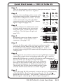
Step 1
Turn off all equipment or disconnect it from power sources. Mount
the transmitter and receiver as required.
Step 2
Connect a low resolution video source to the
transmitter using the BNC connections for
composite or component sources. S-video
can be connected using either the BNC
connectors or the 4-pin mini DIN. (See the
figure at right and page 2-11).
R-Y
S-VID
Component
Y/VID
B-Y/C
R-Y
S-VID
B-Y/C
R-Y
R-Y
S-VID
S-video
Y/VID
B-Y/C
R-Y
S-VID
S-video
Tip
Ring
Sleeves
Tip
Ring
R
Balanced Audio
Tip
Sleeve
L
Tip
Sleeve
R
If required, connect an alarm system to
the transmitter's 2 pole captive screw
connector. (See page 2-13).
Y/VID
L
Connect balanced or unbalanced, stereo
or mono audio input to the transmitter
using the 5 pole, 3.5 mm captive screw
connector. (See the figure at right and
page 2-12).
Step 5
B-Y/C
Composite
Step 3
Step 4
Y/VID
Unbalanced Audio
OPTICAL
Connect the fiber optic cables to the port on the rear of the
transmitter (see the figure at right and page 2-14). Link 1
is essential for video, audio, and RS-232 signals. Link 2 is
required when using RS-232 commands for complete system
configuration.
Tx
Rx
To configure the transmitter and receiver using RS-232 commands,
connect the control device to the three right poles ( ,Tx, and Rx),
labeled RS-232 Remote, on the RS-232 captive screw connector of
the transmitter (see the figure at right and page
OVER FIBER REMOTE
3-3). Alternatively, the host device can be connected
through the front panel Config port (see page 3-2) or
Tx Rx
Tx Rx
the corresponding ports on the receiver (see step 13).
These ports may also be used to configure the system
with the FOX Extender Windows Control Program.
RS-232
Step 6
Step 7
To pass through RS-232 commands to remote devices, independently
of the FOX 2G Tx/Rx AV, use the three left poles (Tx, Rx, and ),
labeled RS-232 Over Fiber. The ground is common for both sets of
RS-232 signals. (See the figure above right and page 3-3).
FOX 2G Tx/Rx AV • Quick Start Guide
QS-1
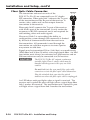
Quick Start Guide — FOX 2G Tx/Rx AV, cont’d
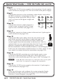
Step 8
Connect the 12 VDC power supply to the transmitter's 2 pole captive
screw connector (see page 2-10). Do not switch on the power supply.
Step 9
Connect the receiver to a low resolution video display using either
the BNC connectors (component, S-video, or
Y/VID
B-Y/C
Y/VID
composite) or the 4-pin mini DIN (S-video
only), as shown in the figure at right and
R-Y
R-Y
S-VID
R-Y
page 2-11.
Component
S-video
B-Y/C
S-VID
Step 10
Connect the receiver's audio output to a
sound system, using the 5 pole, 3.5 mm
captive screw connector (see page 2-12).
Y/VID
B-Y/C
R-Y
S-VID
Composite
Y/VID
B-Y/C
R-Y
S-VID
S-video
Step 11
If required, connect an alarm system to the receiver's 2 pole captive
screw connector (see page 2-13).
Step 12
Connect the fiber optic cable(s) from the transmitter to the
back of the receiver (see the figure at right and page 2-14).
OPTICAL
Link 1 is essential for transmission of video, audio, and
Tx
Rx
control signals from the transmitter to the receiver. Link 2 is
optional, but two-way communication from the Tx port of the
receiver is required to fully configure the system using
RS-232 commands or FOX Extender Windows Control Program.
Link 2 may be connected to another receiver in a daisy chain. In that
case, there is no return link to the transmitter (see page 2-15).
Step 13
Connect the RS-232 control device to this 5 pole captive screw
connector or the front panel Config port. These ports are an
alternative to the transmitter ports (see steps 6 and 7 and page 3-2).
N
If the RS-232 control device is connected to the receiver, fiber
optic Link 2 is required to configure the transmitter.
Step 14
Connect the 12 VDC power supply to the receiver's 2 pole captive
screw connector (see page 2-10).
Step 15
Power up all devices and configure the system using the Simple
Instruction Set (SIS) commands (see page 3-5) or FOX Extender
Windows Control Program (see page 3-15).
QS-2
FOX 2G Tx/Rx AV • Quick Start Guide
Table of Contents
Chapter One • Introduction..................................................... 1-1
About this Manual..................................................................... 1-2
About the FOX 2G Tx/Rx AV................................................... 1-2
FOX 2G Tx/Rx AV Features...................................................... 1-3
FOX 2G Tx/Rx AV Application Diagram.............................. 1-4
Chapter Two • Installation and Setup. ............................ 2-1
Mounting the FOX 2G Tx/Rx AV. .......................................... 2-2
Tabletop placement................................................................ 2-2
Rack Mounting........................................................................ 2-2
UL guidelines for rack mounting............................................2-2
Rack mounting procedures.....................................................2-3
Under-desk mounting............................................................. 2-4
Through-desk mounting......................................................... 2-5
Projector mounting................................................................. 2-6
Front Panel Features.................................................................. 2-8
Rear Panel Features................................................................... 2-9
Operation.................................................................................... 2-10
Power Input........................................................................... 2-10
Video Connections................................................................ 2-11
Audio Connections................................................................ 2-12
Alarm..................................................................................... 2-13
Fiber Optic Cable Connector................................................ 2-14
Daisy Chain Capability.......................................................... 2-15
Chapter Three • Configuration............................................. 3-1
RS-232 Ports................................................................................. 3-2
RS-232 Control of Tx and Rx Units. ...................................... 3-4
Simple Instruction Set (SIS) Commands.............................. 3-5
Introduction to SIS.................................................................. 3-5
Symbols used in this manual................................................. 3-6
Error messages........................................................................ 3-7
Command/Response Table for SIS Commands................. 3-8
FOX 2G Tx/Rx AV • Table of Contents
i
Table of Contents, cont’d
Windows®-Based Program Control. ................................... 3-15
Installing the software......................................................... 3-15
Starting the program............................................................ 3-15
Status area.............................................................................3-16
Memory Preset area..............................................................3-17
Mute area...............................................................................3-17
Video Adjustment area.........................................................3-18
Video Format areas...............................................................3-18
Advanced Configuration area .................................................. 3-19
Audio Adjustment area.........................................................3-20
Firmware for FOX 2G Tx/Rx AV............................................ 3-21
SIS Command Validity Table................................................. 3-21
Appendix A • Reference Information .............................A-1
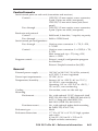
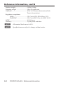
Specifications...............................................................................A-2
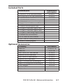
Included Parts..............................................................................A-7
Optional Accessories.................................................................A-7
All trademarks mentioned in this manual are the properties of their respective owners.
68-1466-01
Rev. A
10 08
ii
FOX 2G Tx/Rx AV • Table of Contents
FOX 2G Tx/Rx AV
1
Chapter One
Introduction
About this Manual
About the FOX 2G Tx/Rx AV
FOX 2G Tx/Rx AV Features
FOX 2G Tx/Rx AV Application Diagram
Introduction
About this Manual
This manual contains information about the FOX 2G Tx/Rx AV
family of signal transmitters and receivers, with information on
how to mount, install and operate these units.
In this manual, unless otherwise specified, the term
FOX 2G Tx/Rx AV refers to the features or operation of all four
units. The term transmitter refers to both the multi-mode (MM)
and single mode (SM) transmitters and the receiver refers to
both the MM and SM receivers.
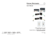
About the FOX 2G Tx/Rx AV
The FOX 2G Tx AV and FOX 2G Rx AV are a high performance,
low resolution video, audio, and data (RS-232) transmitter (Tx)
and receiver (Rx) pairs. Signals are transmitted over fiber optic
cable at rates up to 2 Gbps.
There are four different units:
• FOX 2G Tx AV MM
• FOX 2G Tx AV SM
• FOX 2G Rx AV MM
• FOX 2G Rx AV SM
The MM models have 850 nm multimode small form-factor
pluggable (SFP) modules and carry signals up to 500 m (1640').
The SM models have 1310 nm single mode SFP modules
and carry signals up to 30 km (18 miles). The transmitter is
connected to the receiver using the appropriate fiber optic cable
(SM or MM).
N
The transmitter and receiver must be compatible. Both
must be MM or both must be SM. It is not possible to
mix types.
W
The FOX 2G Tx/Rx AV outputs continuous
invisible light (Class 1 rated), which may be
harmful and dangerous to the eyes; use with
caution.
Do not look into the rear panel fiber optic cable
connectors or into the fiber optic cables themselves.
Plug the attached dust caps into the optical
transceivers when the fiber optic cable is unplugged.
These low resolution FOX 2G video units are not compatible
with the Extron FOX 500 RGB series, the FOX 500 DVI, the
FOX 500 DA6, or the FOX HD-SDI products. However, they are
compatible with the Extron Fiber Matrix units.
1-2
FOX 2G Tx/Rx AV • Introduction
FOX 2G Tx/Rx AV Features
Digitized signal transmission — Ensures perfect image quality.
The non-linearity of the fiber components does not affect signal
quality. Light can be distributed and repeated without signal
degradation or compression.
Long distance transmission — Signals may be transmitted up to
500 m (1,640 feet) over multi-mode (MM) fiber or up to 30 km
(18 miles) over single mode (SM) fiber.
Daisy chain capability — The system can be expanded to
provide output for up to ten display devices.
Integration friendly — A variety of connectors permits input
and output of composite, S-video, or component video signals.
Compatibility with the Extron Fiber Matrix allows the units to
be integrated into more complex A/V systems.
Transmits multiple signal types — Video, audio and data
signals can all be transmitted simultaneously over one fiber. The
units transmit composite, S-Video, or component video signals
and are compatible with NTSC, PAL, and SECAM standards.
All digital, zero compression technology — The FOX 2G AV
delivers uncompressed pixel-for-pixel transmission of video
signals to ensure optimal image quality.
Auto Input Format Detection — The FOX 2G AV transmitter
can be set to detect the incoming video signal format,
automatically reconfiguring itself to transmit the signal. This
feature can reduce the number of required outputs for a matrix
switcher, lowering system cost while improving manageability.
Encoding and decoding — The FOX 2G Tx AV converts
incoming signals to a proprietary format that is passed along
the fiber optic cable to the FOX 2G Rx AV. At the other end of
the cable, the receiver converts the signal to the low resolution
format that matches the needs of the display device.
Output Video Formatting — The user can set the output video
signal format (composite, S-Video, or component) or follow the
format of the source device (video follow).
Picture and audio adjustments — Available picture adjustments
include color, tint, contrast, and brightness. Audio adjustments
include input gain and attenuation, and output level. Both
audio and video can be muted.
Troubleshooting features — A variety of LED signals and
indicators allow easy diagnosis of problems.
Easy configuration — The units can be configured using
Extron's Special Instruction Set (SIS™) or the FOX Extender
Windows Control Program.
FOX 2G Tx/Rx AV • Introduction
1-3
Introduction, cont’d
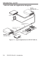
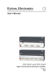
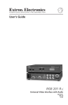
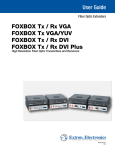
FOX 2G Tx/Rx AV Application Diagram
Extron
FOX 2G Tx AV
Fiber Optic Transmitter
X 2G
FO
2
-23 TE
RS
2 REMO
-23
RS ER
FIB
OV
ER
Tx
Tx
C
B-Y/
Video
DVD/VCR
Combo
12V MA
A
0.6
AV
L
Rx
Tx
M
AR
DIO R
AL
AU
L
1
2
D
O
U
T
Y/VI
T
S
R-
R P
WE U
PO
X
Rx
TICA
OP
Rx
Rx
D
S-VI
Y
Audio
RS-232
Projector
Control
RS-232
Up to 30 km (18.75 miles)
on singlemode fiber
SM Model
Optional Second Fiber Link
for Box to Box
Communications
X 2G
FO
2
-23 TE
RS
2 REMO
-23
RS ER
FIB
OV
ER
Tx
Tx
C
B-Y/
12V MA
A
0.6
Extron
FOX 2G Rx AV
L
DIO R
AU
Extron
MPA 122
AV
L
Rx
Tx
Mini Power Amplifier
M
AR
AL
1
2
D
I
N
P
Y/VI
S
R-
R
WE U
PO
XT
Tx
TICA
OP
Rx
Rx
D
S-VI
Y
RS-232
Audio
Output
Video
Fiber Optic Receiver
Projector
Figure 1-1 — Typical Application for FOX 2G Tx/Rx Av
1-4
FOX 2G Tx/Rx AV • Introduction
FOX 2G Tx/Rx AV
2
Chapter Two
Installation and Setup
Mounting the FOX 2G Tx/Rx AV
Front Panel Features
Rear Panel Features
Operation
Installation and Setup
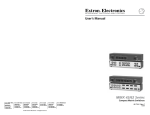
Mounting the FOX 2G Tx/Rx AV
The 1U high, quarter rack wide units can be placed on a
tabletop, mounted in a rack, or mounted under or through
a desk or other furniture. In addition, the receiver can be
mounted close to a projector, using the Extron PMK 350
(PN 70-563-0x).
Tabletop placement
Attach the four included rubber feet to the bottom of the unit
and place it in any convenient location.
Rack Mounting
UL guidelines for rack mounting
The following Underwriters Laboratories (UL) guidelines are
relevant to the safe installation of the FOX 2G Tx/Rx AV in a
rack:
2-2
1.
Elevated operating ambient temperature — If the unit
is installed in a closed or multi-unit rack assembly, the
operating ambient temperature of the rack environment
may be greater than room ambient temperature. Therefore,
install the equipment in an environment compatible with
the maximum ambient temperature (Tma: +122 °F, +50 ° C)
specified by Extron.
2.
Reduced air flow — Install the equipment in the rack
so that the equipment gets adequate air flow for safe
operation.
3.
Mechanical loading — Mount the equipment in the rack
so that uneven mechanical loading does not create a
hazardous condition.
4.
Circuit overloading — Connect the equipment to
the supply circuit and consider the effect that circuit
overloading might have on overcurrent protection and
supply wiring. Give appropriate consideration to the
equipment nameplate ratings when addressing this
concern.
5.
Reliable earthing (grounding) — Maintain reliable
grounding of rack-mounted equipment. Pay particular
attention to supply connections other than direct
connections to the branch circuit (such as the use of power
strips).
FOX 2G Tx/Rx AV • Installation and Setup
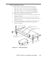
Rack mounting procedures
The units can be mounted in the front or rear of the:
•
RSU 126 (6" deep, 1U rack shelf kit: PN 60-190-10)
•
RSB 126 (6" deep, 1U basic rack shelf: PN 60-604-10)
•
RSU 129 (9.5" deep, 1U rack shelf kit: PN 60-190-01)
•
RSB 129 (9.5" deep, 1U basic rack shelf: PN 60-604-01)
To mount the units, follow these instructions:
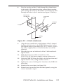
1.
Remove the rubber feet if these have been installed on the
bottom of the unit.
2.
Align the unit on the shelf and secure it to the shelf with
two 4-40 x 3/16" screws in diagonally opposite corners (see
figure 2-1 below).
3.
Install false faceplate(s) or other unit(s) to the rack shelf.
4.
Attach the shelf to the rack with the four provided
10-32 x 3/4" bolts.
1U Universal Rack Shelf
1/2 Rack Width Front False
Faceplate
1/4 Rack Width Front False
Faceplate
Both front false faceplates
use 2 screws.
(2) 4-40 x 3/16"
Screws
Use 2 mounting holes on
opposite corners.
Figure 2-1 — Rack mounting
FOX 2G Tx/Rx AV • Installation and Setup
2-3
Installation and Setup, cont’d
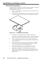
Under-desk mounting
Mount the FOX 2G Tx/Rx AV under a desk or podium using the
optional Extron MBU 125 under desk mounting kit
(PN 70-077-01) as follows:
1.
Remove the rubber feet if these have been installed on the
bottom of the unit.
2.
Secure the mounting brackets to the transmitter or receiver,
using the four 4-40 screws provided (see figure 2-2 below).
Figure 2-2 — Under-desk mounting
2-4
3.
Hold the unit with the brackets attached against the
underside of the table or other furniture. Mark the location
of the screw holes of the bracket on the mounting surface.
4.
Drill four pilot holes, each 3/32" (2 mm) in diameter by
1/4" (6.3 mm) deep in the mounting surface at the marked
screw locations.
5.
Insert #8 wood screws into the four pilot holes. Tighten
each screw into the mounting surface until just less than
1/4" (6.3 mm) of the screw head protrudes.
6.
Guide the mounting screws through the slots in the
brackets and place the unit tight against the surface.
7.
Slide the unit slightly in or out so that the screws are
seated in the narrowest part of the mounting bracket slots;
tighten all four screws to secure the unit in place (see the
figure above).
FOX 2G Tx/Rx AV • Installation and Setup
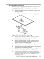
Through-desk mounting
Mount the FOX 2G Tx/Rx AV through a desk or podium using
the optional Extron MBD 129 through-desk mounting kit
(PN 70-077-02) as follows:
1.
Remove the rubber feet if these have been installed on the
bottom of the unit.
2.
Attach the brackets to the transmitter or receiver, using the
four 4-40 screws provided; leave the screws slightly loose.
Figure 2-3 — Through-desk mounting
3.
Hold the unit in position, under the mounting surface.
Mark the location of the four screw holes and the
mounting hole to be cut in the table.
4.
Remove the table material. Test the fit by inserting the
front of the device through the hole. If necessary, use a
rasp or coarse file to enlarge the hole.
5.
Drill four pilot holes, each 3/32" (2 mm) in diameter by
1/4" deep (6.3 mm) deep, as marked on the template.
6.
Attach the brackets to the mounting surface, using the four
#8 wood screws provided with the kit.
7.
Slide the device in or out until the front panel is flush with
the table surface. Tighten the screws installed in step 2.
8.
If the screws are inaccessible to a screwdriver, mark the
location of the unit relative to the bracket, remove the unit
and bracket, tighten the screws and replace the unit as
described in step 6.
FOX 2G Tx/Rx AV • Installation and Setup
2-5
Installation and Setup, cont’d
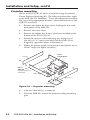
Projector mounting
Mount the FOX 2G Rx AV above a projector using an optional
Extron Projector Mounting Kit. The following intructions apply
to the PMK 350 (PN 70-563-0x). To use other projector mounting
kits, consult the appropriate manual. Mount the receiver on the
PMK 350 as follows:
1.
Remove and retain the four screws holding the front and
back panels of the PMK 350.
2.
Remove the cover sheet.
3.
Remove the rubber feet if these have been installed on the
bottom of the FOX 2G Rx AV.
4.
Secure the receiver to the mounting tray, using two of
the 4-40 x 3/16" screws provided with the PMK 350 in
diagonally opposite corners of the receiver.
5.
Mount the power supply, using the provided plastic ties or
Velcro® strips (see figure 2-4 below).
Extron
FOX 2G Rx AV
Rear Plate
X 2G
232
RS- OTE
232 REM
ER
FO
Tx
Tx
/C
R
WE
PO
I
N
P
U
Y/V
S
R-
XT
12V MA
0.6A
Extron
PMK 350
Rx
AV
AL
Rx
Tx
Rx
RM
Rx
IO
AUD
L
TIC
OP
RSFIB
R
OVE
B-Y
R
ALA
1
2
ID
ID
S-V
Y
U-bolt
Multi-product Projector
Mounting Kit
Power supply
Front Plate
Cover Sheet
Figure 2-4 — Projector mounting
2-6
6.
Add any other unit(s), as required.
7.
Place the PMK 350 around the projector ceiling mounting
pole.
FOX 2G Tx/Rx AV • Installation and Setup
8.
Pass the two legs of the U-bolt through the slotted holes
in the back of the mounting plate, around the mounting
pole, through the holes in the rubber contoured base, and
through the holes in the L bracket (see figure 2-5 below).
Mount Plate
on PMK Tray
Contoured
Base
L-shaped
Bracket
U-bolt
Ceiling
Pole
Figure 2-5 — U-bolt attachment
9.
Align the two small holes in the bottom of the L-shaped
bracket with the holes in the PMK 350 base plate. Insert
and tighten the two provided 6-32 x 5/16" screws. Leave
the screws slightly loose so that the bracket can still be
adjusted.
10. Place the hex nuts on both ends of the U-bolt and handtighten them.
11. Make the necessary cable connections to the
FOX 2G Rx AV, the power supply, and any other units.
12. Slide the PMK 350 along the pole to its final position and
tighten the hex nuts, using a socket wrench.
12. Tighten the screws holding the L-bracket to the PMK 350
base plate.
13. Reattach the cover sheet (see figure 2-4).
14. Reattach and secure the front and back panels, using the
screws retained in step 1.
FOX 2G Tx/Rx AV • Installation and Setup
2-7
Installation and Setup, cont’d
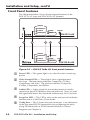
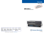
Front Panel Features
The illustration below shows the front panel features of the
FOX 2G Tx AV (top) and FOX 2G Rx AV (bottom):
FORMAT
COMPOSITE
S-VIDEO
AUDIO
COMPONENT
AUTO
CONFIG
FOX 2G Tx AV
VIDEO FIBER OPTIC TRANSMITTER
1
3
2
4
5
FORMAT
COMPOSITE
LOOP-OUT
S-VIDEO
AUDIO
COMPONENT
FOLLOW
CONFIG
FOX 2G Rx AV
VIDEO FIBER OPTIC RECEIVER
Figure 2-6 — FOX 2G Tx/Rx AV front panel features
a
b
c
d
e
2-8
Power LED — This green light is on when the unit is receiving
power.
Video Format LEDs — These lights show signal presence
and type. The transimtter indicates Composite, S-Video,
Component, and Auto. The receiver indicates Composite,
S-Video, Component, and Follow.
Audio LED — Lights when the transmitter detects an audio
signal at or above 35 dB below the nominal level. Stays on until
the signal falls below this threshold continuously for 10 seconds.
Loop-Out LED — This LED is only on the receiver and indicates
that the unit is in the Daisy Chain mode.
Config Port — This 2.5 mm mini jack connector is an alternative
to the rear panel RS-232 connections for configuring the units,
using SIS commands or FOX Extender Windows Control
Program (see Chapter 3).
FOX 2G Tx/Rx AV • Installation and Setup
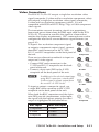
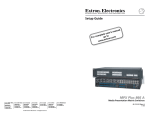
Rear Panel Features
The illustration below shows the rear panel features of the
FOX 2G Tx AV (top) and FOX 2G Rx AV (bottom):
FOX 2G Tx AV
I
N
POWER P
12V
U
0.6A MAX
T
S
RS-232
OVER FIBER REMOTE
Y/VID
Tx Rx
Tx
R
ALARM
1
8
9
RS-232
Y/VID
B-Y/C
Tx Rx
S-VID
11
FOX 2G Rx AV
OPTICAL
Tx Rx
Tx
Rx
AUDIO
L
R-Y
2
10
OVER FIBER REMOTE
O
U
T
POWER P
12V
0.6A MAX U
T
S
Rx
AUDIO
S-VID
7
OPTICAL
Tx Rx
L
R-Y
6
B-Y/C
R
ALARM
1
2
Figure 2-7 — FOX 2G Tx/Rx AV rear panel features
f
g
h
i
j
k
Power input — This 3.5 mm, 2-pole captive screw connector
accepts 12 VDC from an external power supply (provided).
Video connections — Three BNC connectors and one 4-pin mini
DIN S-video connector for video input and output.
Audio connections — A 3.5 mm, 5-pole captive screw connector
for audio input and output.
RS-232 connections — The Remote RS-232 connections allow
the units to be configured using SIS commands or the FOX
Extender Windows Control Program. The Over Fiber RS-232
connections allow pass-through to remote units.
Alarm — When connected to an alarm, this 3.5 mm 2-pole
captive screw connector gives a warning when light signals
have been disconnected, lost, or broken.
Fiber Optic Cable connector — An LC duplex SFP connector
links the transmitter and receiver. An LED above each port
lights when a signal is received.
FOX 2G Tx/Rx AV • Installation and Setup
2-9
Installation and Setup, cont’d
Operation
Power Input
1.
Connect the captive screw connector from the supplied
12 VDC power supply into the power receptacle.
N
POWER
12V
0.6A MAX
The FOX 2G Tx/Rx AV does not have a remote powering
feature. Both the transmitter and the receiver require
their own separate power supply.
Power Receptacle
DC Power Cord
Captive Screw Connector
Negative
+12 VDC
AC Power Cord
External
Power Supply
(12 VDC, 1 A )
Figure 2-8 — Connecting power
N
The length of the exposed wires in the stripping process
is critical. The ideal length is 3/16” (5 mm). Any longer
and the exposed wires may touch, causing a short circuit
between them. Any shorter and the wires can be easily
pulled out even if tightly fastened by the captive screws.
C
2.
2-10
Do not tin the wires. Tinned wire does not hold its
shape and can become loose over time.
Connect the AC power cord of the power supply unit to a
110 or 220 VAC electrical source.
FOX 2G Tx/Rx AV • Installation and Setup
Video Connections
The FOX 2G Tx/Rx AV accepts a single low resolution video
signal (composite, S-video and low resolution component video)
and outputs a single low resolution video signal (composite,
S-video and low resolution component video). It is not
compatible with RGB or HDTV 480p, 720p, or 1080i component
video signals.
The transmitter converts incoming signals to a proprietary
format and passes them along the fiber optic cable to the FOX
2G Rx AV. The receiver converts the signal to a format that
matches the display requirements. SIS™ commands are used to
configure the receiver to convert between signal formats (see
page 3-10).
To input a low resolution component signal,
or output a component output signal, connect
three BNC male connectors to the Y/VID,
B-Y/C, and R-Y receptacles on the back panel of
the unit.
There are two alternative methods to input or
output an S-video signal:
• Connect BNC male connectors to the
Y/VID and B-Y/C receptacles on the back
panel of the unit.
• Connect a 4-pin mini DIN to the S-VID
receptacle on the back panel of the unit.
N
In addition to the selected output type,
using BNC connectors, a transcoded
S-video signal is always output from
the receiver's S-VID socket.
To input or output a composite signal, use
a single BNC male connector to the Y/VID
receptacle on the back panel of the unit.
When both the BNC connectors and the 4-pin
mini DIN provide simultaneous video input,
the signal with the highest priority for video
output is highlighted in the table below:
BNC Input
Mini DIN Input
Component
S-Video
S-Video
S-Video
Composite
S-Video
Y/VID
B-Y/C
R-Y
S-VID
Component
Y/VID
B-Y/C
R-Y
S-VID
S-video
Y/VID
B-Y/C
R-Y
S-VID
S-video
Y/VID
B-Y/C
R-Y
S-VID
Composite
FOX 2G Tx/Rx AV • Installation and Setup
2-11
Installation and Setup, cont’d
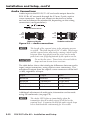
Audio Connections
Audio input to the FOX 2G Tx AV and audio output from the
FOX 2G Rx AV are made through the 3.5 mm, 5-pole, captive
screw connectors. Input and output can be mono or stereo
and can be balanced or unbalanced, depending on the wiring
connections (see figure below).
Do not tin the wires!
R
Tip
Sleeve
Balanced Audio
R
Tip
Sleeve
L
L
Tip
Ring
Sleeves
Tip
Ring
Unbalanced Audio
Figure 2-9 — Audio connections
N
The length of the exposed wires in the stripping process
is critical. The ideal length is 3/16” (5 mm). Any longer
and the exposed wires may touch, causing a short circuit
between them. Any shorter and the wires can be easily
pulled out even if tightly fastened by the captive screws.
C
Do not tin the wires. Tinned wire does not hold its
shape and can become loose over time.
The table below shows the initial gain differences between audio
input/output connectors, using captive screw connectors. The
unbalanced output from the captive screw connector will be half
(-6 dB), regardless of input.
Input
Output
Gain
Balanced
Balanced
0 dB (unity)
Balanced
Unbalanced
-6 dB (half)
Unbalanced
Balanced
0 dB
Unbalanced
Unbalanced
-6 dB
Additional adjustment of audio gain/attenuation can be made
using SIS commands (see page 3-8).
N
2-12
The Audio LED lights up immediately when the
transmitter detects an audio signal 35 dB below the
nominal level. It remains lit until the audio signal drops
below that threshold continuously for 10 seconds.
FOX 2G Tx/Rx AV • Installation and Setup
Alarm
ALARM
The alarm pins, labeled 1 and 2, (see figure at right)
on the rear panel of the FOX 2G Tx/Rx AV act
as a short when activated. They do not produce
any discrete on/off voltage signals but, instead,
act as an internal relay that will either connect or
disconnect an external alarm circuit.
1 2
For the FOX 2G Tx AV, the alarm state is activated
when link 2 is absent. For the FOX 2G Rx AV, the
alarm state is activated when link 1 is absent.
When power is lost, both the alarm state is
activated for both units.
N
The length of the exposed wires in the
stripping process is critical. The ideal
length is 3/16” (5 mm). Any longer and
the exposed wires may touch, causing a
short circuit between them. Any shorter and the wires
can be easily pulled out even if tightly fastened by the
captive screws.
C
Do not tin the wires. Tinned wire does not hold its
shape and can become loose over time.
FOX 2G Tx/Rx AV • Installation and Setup
2-13
Installation and Setup, cont’d
Fiber Optic Cable Connector
The transmitter and receiver units of the
FOX 2G Tx/Rx AV are connected by an LC duplex
SFP connector. Fiber optic link 1 connects the Tx port
of the transmitter and the Rx port of the receiver. It
carries video, audio and/or data output from the
transmitter to the receiver.
OPTICAL
Tx
Rx
Fiber optic link 2 connects the Tx port of the receiver
with the Rx port of the transmitter. It only carries the
responses to RS-232 commands and is not required for
transmitting video and audio signals.
However, if link 2 is not enabled, the ability to
configure the system through SIS commands is limited
by the lack of communication from the receiver to
the transmitter. All commands issued through the
transmitter are valid but responses to status queries
may return invalid data.
OPTICAL
Tx
Rx
Signals may be transmitted 500 m (1,640 feet) over multi-mode
(MM) fiber and 30 km (18 miles) over single mode fiber. An MM
transmitter must always be connected to a MM receiver and an
SM transmitter can only be connected to a SM receiver.
W
The FOX 2G Tx/Rx AV outputs continuous
invisible light (Class 1 rated), which may be
harmful and dangerous to the eyes; use with
caution.
Do not look into the rear panel fiber optic cable
connectors or into the fiber optic cables themselves.
Plug the attached dust caps into the optical
transceivers when the fiber optic cable is unplugged.
An LED above each port lights when a signal is received. The
receiver unit's optical Rx port will light when a signal from fiber
link 1 reaches the receiver. The transmitter unit's optical Rx port
will light when a signal from link 2 reaches the transmitter.
2-14
FOX 2G Tx/Rx AV • Installation and Setup
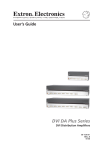
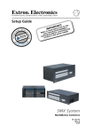
Daisy Chain Capability
FOX 2G Rx AV receivers have a loop-out mode that allows a
signal to be passed from the receiver along a daisy chain of
to up to ten receivers, with a display device attached to each
receiver. The loop-out mode is set using RS-232 commands. For
more information, see chapter 3, "Simple Instruction Set (SIS)
Commands".
All receivers in the daisy chain must be compatible, i.e. they
must all be SM or all be MM models, connected with the
appropriate fiber optic cable. Each receiver receives a signal
at its Rx fiber optic port and passes the signal to the next unit
through its Tx port.
N
In daisy chain mode, the Tx port is used to pass audio
and video signals to the next receiver in the daisy chain.
As a result, the Tx port is not available for bidirectional
communication and there are limitations on system
configuration with SIS commands.
N
When multiple receivers are in daisy chain mode,
RS-232 commands issued through the transmitter will
be passed to every receiver but commands issued through
a receiver will apply only to that receiver. Configuring
each receiver independently, matches each output signal
to the unique needs of the display device.
Extron
FOX 2G Tx AV
Fiber Optic Transmitter
00
X3
FO
ICA
OPT
2
TE
RS-23
2 REMO
RS-23
FIBER
OVER
Tx
Tx
C
B-Y/
Video
DVD/VCR
Combo
ER
POW
I
N
P
U
12V MAX T
S
0.6A
Tx
L
Rx
Rx
L
O
AUDI R
M
ALAR
1
2
D
Y/VI
D
S-VI
R-Y
Audio
RS-232
Projector
Control
RS-232
FOX 2G Rx AV
Receiver
00
Rx
X3
FO
ICA
OPT
2
TE
RS-23
2 REMO
RS-23
FIBER
OVER
Tx
Tx
C
B-Y/
FOX 2G Rx AV
ER
POW
O
U
T
P
U
12V MAX T
0.6A
S
L
Rx
Rx
L
O
AUDI R
M
ALAR
1
2
D
Y/VI
D
S-VI
R-Y
Receiver
00
Rx
X3
FO
ICA
2
TE
RS-23
2 REMO
RS-23
FIBER
OVER
Tx
Tx
C
B-Y/
FOX 2G Rx AV
ER
POW
O
U
T
P
U
12V MAX T
0.6A
S
L
OPT
Rx
M
Rx
O
AUDI
L
Up to 30 km (18.75 miles)
on singlemode fiber
(SM model)
ALAR
R
1
2
D
Y/VI
D
S-VI
R-Y
Receiver
00
Rx
X3
FO
ICA
2
TE
RS-23
2 REMO
RS-23
FIBER
OVER
Tx
Tx
C
B-Y/
ER
POW
O
U
T
P
U
12V MAX T
0.6A
S
To Next
Receiver
L
OPT
Rx
M
Rx
O
AUDI
L
ALAR
R
1
2
RS-232
D
Y/VI
D
S-VI
R-Y
Video
Projector
Figure 2-10 — Daisy Chain Mode
FOX 2G Tx/Rx AV • Installation and Setup
2-15
Installation and Setup, cont’d
2-16
FOX 2G Tx/Rx AV • Installation and Setup
FOX 2G Tx/Rx AV
3
Chapter Three
Configuration
RS-232 Ports
RS-232 Control of Tx and Rx Units
Simple Instruction Set (SIS) Commands
Command/Response Table for SIS Commands
Windows®-Based Control Program
Configuration
RS-232 Ports
Both the FOX 2G Tx AV and FOX 2G Rx AV have a front panel
TRS port and a rear panel captive screw port, which can provide
SIS commands to configure the tranmitter/receiver settings
when connected to a control device.
SIS commands for the FOX 2G Tx/Rx AV are shown (starting on
page 3-8).
N
The two comm ports work in parallel. However,
depending on the computer or the communication
settings, connecting to both comm ports at once may
result in one or both ports not working. Extron
recommends that only one comm port (front or back) is
used at a time.
The protocol for both ports is 9600 baud, no parity, 8 data bits,
1 stop bit, and no flow control.
N
Both RS-232 Remote and RS-232 Over Fiber signals
require fiber optic link 1 and link 2 for full functionality
(see page 3-4).
The front panel Config port uses a 2.5 mm mini jack connector.
Tip
Ring
Sleeve (Gnd)
2.5 mm TRS connector
Pin
Tx
Rx
TRS
Tip
Ring
Sleeve
Function
Transmit data
Receive data
Signal ground
Figure 3-1 — Front panel RS-232 port
3-2
FOX 2G Tx/Rx AV • Configuration
As an alternative to the front panel TRS port, the RS-232 Remote
port, on the rear panel, uses three connectors in a 5-pole captive
screw connector.
Pin
TX
RX
Gnd
RS-232
OVER FIBER REMOTE
Tx Rx
Tx Rx
Function
Transmit data
Receive data
Signal ground
Controlling
Device
Do not tin the wires!
Bidirectional
Receive (Rx)
Transmit (Tx)
Ground ( )
Receive (Rx)
Transmit (Tx)
Ground ( )
Figure 3-2 — Rear panel RS-232 REMOTE port
In addition, on the rear panel, the units have RS-232 Over Fiber
pass-through ports. These ports allow RS-232 commands to be
passed from the control device to remote devices over the fiber
optic cable with speeds up to 115 kbps.
N
The FOX 2G Tx/Rx AV will not respond to, or generate
a response to, any commands passed through the
"RS-232 Over Fiber" ports. Refer to the user's manual
of the device being controlled for the appropriate SIS
commands.
Pin
TX
RX
Gnd
RS-232
OVER FIBER REMOTE
Tx Rx
Tx Rx
Function
Transmit data
Receive data
Signal ground
Do not tin the wires!
Controlling
Device
Bidirectional
Ground ( )
Receive (Rx)
Transmit (Tx)
Ground ( )
Receive (Rx)
Transmit (Tx)
Figure 3-3 — Captive screw connection for rear
panel RS-232 OVER FIBER port
FOX 2G Tx/Rx AV • Configuration
3-3
Configuration, cont’d
RS-232 Control of Tx and Rx Units
When the FOX 2G Tx/Rx AV is configured by RS-232
commands, some commands are processed by the transmitter
and others are processed by the receiver. The SIS commands do
not distinguish between the two units. The system routes the
commands based on where they are processed.
A system block diagram showing which functions are processed
by the transmitter and which are processed by the receiver is
shown below:
Fiber Link 1
Transmitter
Process
Input configuration
Audio gain
Fiber Link 2
(optional)
Receiver
Process
Color
Tint
Brightness
Contrast
Video mute
Output configuration
Daisy chain/
loop out mode
Audio mute
Audio output level
Figure 3-4 — System block diagram
For full functionality, both fiber optic links must be enabled.
If only Link 1 is enabled, the ability to configure the system
through SIS commands is limited by the lack of return
communication from the receiver to the transmitter:
• All configuration carried out using the transmitter will be
processed normally because only fiber Link 1 is required.
• Queries from the transmitter about the status of receiver
settings will not be processed correctly because fiber Link 2 is
required to carry the return signal.
• The receiver cannot be used to configure the transmitter
because fiber Link 2 is required.
The lack of communication between the transmitter and the
receiver can result in mismatches in the value settings of the
two units, which may cause confusion with control systems
or software applications. To avoid this confusion, within four
seconds of Link 2 becoming active, the receiver settings are
automatically copied to the transmitter to ensure settings for
both units match.
N
3-4
When the receiver settings are copied to the transmitter,
existing transmitter settings are overwritten and it may
be necessary to update those values.
FOX 2G Tx/Rx AV • Configuration
Simple Instruction Set (SIS™) Commands
Introduction to SIS
SIS commands consist of a string (one or more characters per
command field). For the FOX 2G Tx/Rx AV, apart from setting
audio gain ("G") and attenuation ("g"), upper and lower case
characters may be used interchangeably. Commands do not
require any special characters to begin or end the command
string. Each response from the unit ends with a carriage return
and a line feed (CR/LF = ]), which signals the end of the
response character string.
When the FOX 2G Tx/Rx AV unit is first switched on,
depending on the model, it sends one of the following messages:
© Copyright 2008, Extron Electronics, FOX 2G Tx AV, Vx.xx,
60-941-11] or
© Copyright 2008, Extron Electronics, FOX 2G Tx AV, Vx.xx,
60-941-12] or
© Copyright 2008, Extron Electronics, FOX 2G Rx AV, Vx.xx,
60-941-21]
© Copyright 2008, Extron Electronics, FOX 2G Rx AV, Vx.xx,
60-941-22]
where V x.xx is the firmware version number and 60-941-xx is
the product catalog number.
FOX 2G Tx/Rx AV • Configuration
3-5
Configuration, cont’d
Symbols used in this manual
When programming in the field, certain characters are most
conveniently represented by the hexadecimal equivalent of
their ASCII value. For convenience, the table below shows the
hexadecimal equivalent of each ASCII command:
ASCII to HEX Conversion Table
Space
.
N
Apart from G (gain) and g (attenuation), upper and
lower case characters can be used interchangeably in SIS
commands for this product. For example, on page 3-8,
either "C" or "c" can be used to set the color value.
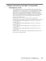
The symbols (X/ values) defined in this section are the variables
used in the fields of the command response table that begins on
page 3-8.
] — carriage return with line feed
} — carriage return (no line feed)
• — space character
E — Escape key
X! — Input video type
0 = Auto
4 = Component
5 = S-video
6 = Composite
X@ — Color, tint, contrast, or brightness adjustment (0 to 127)
X# — Auto Memory, blanking, or audio mute status
0 = disabled
1 = enabled
3-6
FOX 2G Tx/Rx AV • Configuration
X$ — Output video type
0 = Follow input type
6 = Component
7 = S-video
8 = Composite
X% — Audio gain (0 to 10)
X^ — Audio attenuation (-18 to 0)
X& — Audio level (-18 to +10)
X* — Audio output level
0 = Consumer level (-10 dBV) (default)
1 = Professional level (+4 dBu)
X( — Test pattern
0 = Test pattern off
1 = Color bars
2 = Grayscale
3 = Alternating pixels
X1) — Link #2 transmission status
0 = disables link #2
1 = enables link #2 from receiver back to transmitter
2 = enables daisy chain mode on receiver
X1! — SM (single mode) or MM (multimode)
X1@ — Tx (transmitter) or Rx (receiver)
X1# — Memory presets (1 to 30)
X1$ — Internal temperature in degrees Fahrenheit and Celsius:
(xxxF xxC)
Error messages
E10 — Invalid command
E13 — Invalid parameter
E14 — Not valid for this configuration
FOX 2G Tx/Rx AV • Configuration
3-7
Command
FOX 2G Tx/Rx AV • Configuration
ASCII Command
Response
Additional description
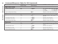
Specify input setting
X!\
TypX!]
Sets format of input video signal (X!)
0 = Auto
4 = Component
5 = S-Video
6 = Composite
View current input setting
\
X!]
Displays current input video format
Specify color value
X@C
ColX@]
Sets color value for video signal (X@ from
0 to 127)
Increment color value
+C
ColX@]
Increases color value by 1
Decrement color value
-C
ColX@]
Decreases color value by 1
View current color value
C
X@]
Displays current color value
Specify tint value
X@T
TinX@]
Sets tint value for video signal (X@ from 0
to 127)
Increment tint value
+T
TinX@]
Increases tint value by 1
Decrement tint value
-T
TinX@]
Decreases tint value by 1
View current tint value
T
X@]
Displays current tint value
(host to unit)
(unit to host)
Input video format
Adjust color
Adjust tint
Configuration, cont’d
3-8
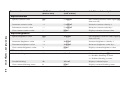
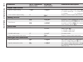
Command/Response Table for SIS Commands
Command
ASCII Command
Response
Additional description
Specify contrast value
X@^
ConX@]
Sets contrast value for video signal (X@
from 0 to 127)
Increment contrast value
+^
ConX@]
Increases contrast value by 1
Decrement contrast value
-^
ConX@]
Decreases contrast value by 1
View current contrast value
^
X@]
Displays current contrast value
Specify brightness value
X@Y
BrtX@]
Sets brightness value for video signal (X@
from 0 to 127)
Increment brightness value
+Y
BrtX@]
Increases brightness value by 1
Decrement brightness value
-Y
BrtX@]
Decreases brightness value by 1
View current brightness value
Y
X@]
Displays current brightness value
1B
Blk1]
Blanks selected input (X#)
0 = Disables blanking or mute
1 = Enables blanking or mute
Disable blanking
0B
Blk0]
Displays selected input
View current blanking status
B
X#]
Displays current blanking status
(host to unit)
(unit to host)
Adjust contrast
Adjust brightness
FOX 2G Tx/Rx AV • Configuration
Video mute
Enable blanking
3-9
FOX 2G Tx/Rx AV • Configuration
ASCII Command
Response
Additional description
Specify output setting
6* X$ #
SynX$]
Sets format of output video signal (X$)
0 = Follow input type 6 = Component
7 = S-Video
8 = Composite
View current output setting
6#
X$]
Displays current output video format
Recall Preset
X1#.
RprX1#]
A period (.) follows X1# in the command.
Recalls memory preset (X1#) from 1 to 30
Save Preset
X1#,
SprX1#]
A comma (,) follows X1# in the command.
Saves memory preset (X1#)
Enable audio mute
1Z
Amt1]
Mutes audio (X#)
0 = Disables audio mute
1 = Enables audio mute
Disable audio mute
0Z
Amt0]
Un-mutes audio
View current audio mute status
Z
X#]
Displays current audio mute status
Specify gain value
X%G
AudX%]
Sets value of audio gain. Upper case "G"
only for configuring gain (X% from 0 to 10)
Specify attenuation value
X^g
AudX^]
Sets value of audio attenuation. Lower case
"g " only for configuring attenuation (X^
from 0 to -18)
(host to unit)
(unit to host)
Output video format
Memory Presets
Audio mute
Audio gain and attenuation
Configuration, cont’d
3-10
Command
Command
ASCII Command
Response
Additional description
Increment audio level
+G
+g
AudX&]
AudX&]
Increases gain (G) or attenuation (g) by 1.
Audio level adjustment range (X& from -18
to +10)
Decrement audio level
-G
-g
AudX&]
AudX&]
Decreases gain (G) or attenuation (g) by 1
View current audio level
G
g
AudX&]
AudX&]
Displays current value for gain (G) or
attenuation (g)
Set to consumer level
40*0#
Lvl0
Sets audio output to consumer level (X*)
0 = Consumer level (-10 dBV) — default
1 = Professional level (+4 dBu)
Set to professional level
40*1#
Lvl1
Sets audio output to professional level
View current output level status
40#
X*]
Displays current audio output level
Disable Auto Memory
55*0#
Img0]
Disables Auto Memory
Enable Auto Memory
55*1#
Img1]
Enables Auto Memory
View current Auto Memory setting
55#
X#]
View the current Auto Memory setting (X#)
0 = disabled; 1 = enabled
(host to unit)
(unit to host)
Audio output level
FOX 2G Tx/Rx AV • Configuration
Auto Memory
3-11
FOX 2G Tx/Rx AV • Configuration
ASCII Command
Response
Additional description
55*2#
Img]
Returns video adjustments (color, contrast,
tint, and brightness) to default values (64)
Color bars
1J
Tst1]
Sets color bars test pattern on (X()
0 = test pattern off 1 = color bars
2 = grayscale
3 = alternating pixels
Grayscale
2J
Tst2]
Sets grayscale test pattern on
Alternating pixels
3J
Tst3]
Sets alternating pixels test pattern on
Off
0J
Tst0]
Sets test pattern off
View current test pattern status
J
X(]
Displays current test pattern status
Disable
66*0*0#
Rle*0*0]
Disables link #2 (X1))
0 = disables link #2 (receiver to transmitter)
1 = enables link #2
2 = enables receiver daisy chain mode
Enable
66*0*1#
Rle*0*0]
Enables link #2
Daisy chain
66*0*2#
Rle*0*0]
Enables receiver daisy chain mode
View current Link #2 status
66*0#
0*X1)]
Displays current link #2 status
This command will only be available on the
reciever unit; the transmitter will respond
with an E14 error code.
(host to unit)
(unit to host)
Auto Image
Trigger
Test Pattern
Link #2 Transmission
Configuration, cont’d
3-12
Command
Command
ASCII Command
Response
Additional description
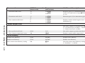
General information
I
1LinkX#•2LinkX#•VidX#
•AudX#•X1!•X1@]
X#
Query firmware (F/W) version
Q
x.xx]
Displays current F/W version
Query all F/W versions
0Q
x.xx-x.xx-x.xx-x.xx]
Diplays information about all F/W versions
Query Factory F/W version
32Q
x.xx]
Displays factory loaded F/W version
Query updated F/W version
34Q
x.xx]
Displays updated F/W version
Query factory FPGA version
33Q
x.xx]
Displays factory loaded Field Programable
Gate Array (FPGA) version
Query updated FPGA version
35Q
x.xx]
Displays updated FPGA version
Query part number
N
60-941-zz]
Displays the unit's part number
Query other unit part number
1N
60-941-zz]
Displays the part number of other
connected box.
(host to unit)
(unit to host)
Information Request
FOX 2G Tx/Rx AV • Configuration
Link #1: active signal present (1) or
absent (0) •
X# Link #2: active signal present (1) or
absent (0) •
X# video output signal enabled (1) or
disabled (0) •
X# audio signal enabled (1) or
disabled (0) •
X1! SM or MM •
X1@ Tx or Rx
3-13
FOX 2G Tx/Rx AV • Configuration
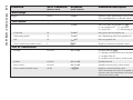
ASCII Command
Response
Additional description
View Link 1 Status
1S
X#]
Displays Link 1 status (X#)
0 = active signal absent
1 = active signal present
View Link 2 Status
2S
X#]
Displays Link 2 status
View input video status
3S
X#]
Displays input video status
View input audio status
4S
X#]
Displays input audio status
View internal temperature
20S
X1$]
Displays internal temperature in degrees
F&C
System Reset (factory default)
EZXXX}
Zpx]
Resets unit to all factory default values
Reset audio settings
EZA}
Zpa]
Resets all audio settings to factory default
values
Reset presets
EZG}
Zpg]
Rests all memory presets to factory default
values
(host to unit)
(unit to host)
Status Request
Factory Defaults
Configuration, cont’d
3-14
Command
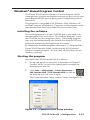
Windows®-Based Program Control
The Extron FOX Extender Windows Control Program (WCP)
communicates with the transmitter and receiver pair via the rear
panel Remote RS-232 port or front panel Configuration port of
either unit.
The program is compatible with Windows 2000, Windows XP
and later versions of Windows. Upgrades to the program can be
downloaded from the Extron Web site (www.extron.com).
Installing the software
The control program is on the CD-ROM that is provided with
the transmitter and/or receiver. To install the program, insert
the CD-ROM into the computer's drive. If the setup program
does not start automatically, run Launch.exe from the CD and
follow the instructions that appear on the screen.
By default, the Installer program will create a C:\Program Files\
Extron\Fox Extenders folder, containing the FOX Extender
Windows control program. An icon may also be placed on the
Windows desktop.
Starting the program
Start the Extron FOX Extender WCP as follows:
1.
Set up and power on the units as described in Chapter 2.
Connect the PC to one of the control ports on either the
transmitter or receiver.
2.
Click Start > All Programs > Extron Electronics >
FOX Extender WCP > FOX Extender WCP or click on
the desktop icon (see icon at right).
The Communication Setup window opens (see figure 3-5):
Figure 3-5 — Communication Setup window
FOX 2G Tx/Rx AV • Configuration
3-15
Configuration, cont’d
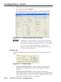
3.
Select the Com port to which your transmitter or receiver is
connected and click Connect.
The Communication Setup window closes and the FOX
Extender WCP window comes into focus (see figure 3-6).
Figure 3-6 — FOX Extender WCP window
N
Only Link 1, connecting the Tx port of the transmitter
to the Rx port of the receiver, is required for video, audio,
and serial command transmission. Link 2 is not required
but, if it is not enabled, the ability to configure the
system is limited by a lack of communication from the
receiver to the transmitter.
Status area
The Status area provides visual indications of the connection
status:
Figure 3-7 — Status area
3-16
•
Video present indicator — Shows green to indicate the
presence of Composite, S-Video, or Component video
signals.
•
Audio present indicator — Shows green when the
transmitter detects an audio signal at or above 35 dB below
the nominal level. Stays on until the signal falls below this
threshold continuously for 10 seconds.
FOX 2G Tx/Rx AV • Configuration
•
Loop-out indicator — Only visible if the computer is
connected to the receiver.
•
Link 1 indicator — Shows green when the receiver detects
light on Link 1 (connecting the Tx port of the transmitter to
the Rx port of the receiver). The receiver reports the status
to the transmitter over Link 2.
N
•
If the computer is connected to either of the transmitter's
control ports and Link 2 is disconnected, the Link 1
indicator will not show green because, when the receiver
detects light on Link 1, it will not be able to pass that
information to the transmitter.
Link 2 (Optional) indicator — Shows green when the
transmitter detects light on Link 2 (connecting the Tx
port of the receiver to the Rx port of the transmitter). The
transmitter reports the status to the receiver via Link 1.
The status area also shows the unit (the transmitter or receiver)
to which the computer is connected, the unit at the other end of
the fiber optic cable and the COM port on the computer that is
connected to the unit.
It also provides information about the horizontal and vertical
frequencies of the input signal.
Memory Preset area
The Memory Preset area provides tools to save and recall
memory presets:
Figure 3-8 — Memory Preset area
Memory Presets save the values of color, tint, contrast, and
brightness.
Mute area
The Mute area provides radio buttons that allow the video and/
or audio to be muted.
Figure 3-9 — Mute area
FOX 2G Tx/Rx AV • Configuration
3-17
Configuration, cont’d
Video Adjustment area
The Video Adjustment area allows adjustments to the color, tint,
contrast, and brightness of the picture that is displayed.
Figure 3-10 — Video Adjustment area
Video Format areas
The Video Format areas (Input Video Format and Output Video
Format) provide radio buttons that allow the input format (auto,
component, S-video, or composite) and output format (follow
input type, component, S-video, or composite) to be selected.
Figure 3-11 — Video Format area
N
The transmitter converts the input signal into a
proprietary signal type, which passes through Link 1 to
the receiver. The receiver converts the signal back to the
required signal type. This allows the input signal to be
transcoded to meet the requirements of the output device.
When Auto is selected for the input format, the transmitter will
automatically detect the signal type. When follow input type is
selected for the output format, the output signal will be in the
same format as the original input signal.
3-18
FOX 2G Tx/Rx AV • Configuration
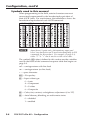
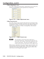
Advanced Configuration area
Figure 3-12 — Advanced Configuration area
Link 2/Daisy Chain Mode — Provides radio buttons to choose
the mode for the receiver's Tx port. If it is connected to the
transmitter, the link may be enabled or disabled. Alternatively,
the port may be connected to another receiver with the Daisy
Chain mode enabled.
Auto Memory — May be switched on or off, using radio
buttons. When Auto Memory is on, previously saved values
such as color, tint, contrast, and brightness will be applied
whenever the vertical field rate of the input changes.
Auto Image — Returns the video adjustment settings of color,
tint, contrast, and brightness back to their default values (64).
Test Patterns — Allow the user to select one of three built-in test
patterns (color bars, grayscale, or alternating pixels), which help
calibrate the display device. When Off is selected, the receiver
outputs the video signal from the source device.
FOX 2G Tx/Rx AV • Configuration
3-19
Configuration, cont’d
Audio Adjustment area
Figure 3-13 — Audio Adjustment area
Audio Gain/Attenuation — Provides a click and drag slider
control to select the input audio gain or attenuation value, from
-18 dB to +10 dB in 1.0 dB increments.
N
Changes to the input gain or attenuation are made in
the transmitter. If the control computer is connected
to the receiver and Link 2 is not active, the gain and
attenuation values cannot be changed.
Audio Output Level — Provides radio buttons to allow a choice
between consumer level (-10 dBV) or professional level (+4 dBu)
for the audio output.
3-20
FOX 2G Tx/Rx AV • Configuration
Firmware for FOX 2G Tx/Rx AV
Firmware can be downloaded onto the unit from the Extron Web
site (www.extron.com). The transmitter and receiver require
different firmware and must both be upgraded separately.
SIS Command Validity Table
If only one fiber optic channel is enabled, the ability to configure
the system through SIS commands is limited by the lack of
return communication from the receiver to the transmitter.
All commands issued through the transmitter are valid because
link 1 allows signals to be forwarded to the receiver. However,
responses to queries originating from the transmitter about the
status of the receiver will return invalid data.
All configuration of the receiver by commands issued through
the receiver will be valid. Attempts to configure the the
transmitter through the receiver in the absence of link 2 will be
invalid.
The following table shows the validity of commands issued
through the receiver when only link 1 is active:
Adjustment
Color
Valid
Tint
Valid
Brightness
Valid
Contrast
Valid
Audio gain/
attenuation
Invalid
Audio mute
Valid
Audio output level
Valid
Output configuration
Valid
Input configuration
Invalid
Daisy chain mode
Valid
Test pattern
Valid
Video mute
Valid
FOX 2G Tx/Rx AV • Configuration
3-21
Configuration, cont’d
3-22
FOX 2G Tx/Rx AV • Configuration
FOX 2G Tx/Rx AV
A
Appendix A
Reference Information
Specifications
Included Parts
Optional Accessories
Reference Information
Specifications
N
The FOX 2G AV consists of a transmitter (FOX 2G Tx AV) and
a receiver (FOX 2G Rx AV) with one or two fiber optic cables
linking the two units.
N
The analog video input signal is digitized pixel for pixel in the
transmitter, sent digitally through the fiber cable, and converted
back to analog video in the receiver.
N
The analog audio signal(s) is (are) digitized in the transmitter,
sent through the fiber cable, and converted back to analog in the
receiver.
N
These transceivers are class 1 laser products. They meet the
safety regulations of IEC-60825, FDA 21 CFR 1040.10, and
FDA 21 CFR 1040.11.
Optical fiber interconnection between transmitter and
receiver
Number/type................................. 1 or 2 fiber optic
N
Only one fiber is required to transmit video, audio, and
unidirectional data. A second fiber is required to transit return
data for bidirectional control/communication
Connectors...................................... 2 LC connectors
Operating distance......................... 30 km (18.75 miles) with singlemode (SM)
cables with an SM model
500 m (1640') with multimode (MM) cables
with an MM model
N
Operating distance is approximate. These are typical distances.
The maximum distance may be greater than these numbers
depending on factors such as fiber type, fiber bandwidth,
connector splicing, losses, modal or chromatic dispersion,
environmental factors and kinks.
Nominal peak wavelength........... 850 nm for FOX 2G AV MM model;
1310 nm for FOX 2G AV SM model
Data rate.......................................... 2.125 Gbps
Transmission power
Singlemode.......................... -5 dBm, typical
Multimode........................... -5 dBm, typical
A-2
FOX 2G Tx/Rx AV • Reference Information
Maximum receiver sensitivity
Singlemode.......................... -18 dBm, typical
Multimode........................... -12 dBm, typical
Optical loss budget
Singlemode.......................... 13 dB, maximum
Multimode........................... 7 dB, maximum
Video
Gain.................................................. Unity
Standards
Input..................................... NTSC 3.58, NTSC 4.43, PAL, SECAM,
autodetected
Output.................................. NTSC 3.58, PAL (follows input vertical
rate)
Decoder type................................... Adaptive 2D, digital comb filter
Video input — transmitters
Number/type................................. 1 component (Y, R-Y, B-Y), S-video,
composite video
Connectors...................................... 1 x 3 female BNC or (1) female 4-pin mini
DIN for S-video
Nominal level................................. 1.0 Vp-p for Y of component video and
S-video, and for composite video
0.7 Vp-p for R-Y and B-Y of component
video
0.3 Vp-p for C of S-video
Minimum/maximum levels......... Analog: 0.3 V to 1.5 Vp-p with no offset
Impedance....................................... 75 ohms @ 5 MHz
Return loss....................................... -30 dB for Y/VID, B-Y/C, R-Y @ 5 MHz
Input coupling................................ AC
Video output — receivers
Number/type................................. 1 component (Y, R-Y, B-Y) video, S-Video,
composite video
Connectors...................................... 1 x 3 female BNC or (1) female 4-pin mini
DIN
Nominal level................................. 1.0 Vp-p for of Y component video and
S-video, and for composite video
0.7 Vp-p for R-Y and B-Y of component
video
0.3 Vp-p for C of S-video
Minimum/maximum levels......... 0.3 V to 1.5 Vp-p
Impedence....................................... 75 ohms @ 5 MHz
FOX 2G Tx/Rx AV • Reference Information
A-3
Reference Information, cont’d
Return loss....................................... <-40 dB @ 5 MHz
DC offset.......................................... + 350 mV, maximum, with input at 0 offset
Video delay..................................... 1-2 frames
Audio
Gain
Range................................... Adjustable, -18 to +10 dB; default
Default................................. Unbalanced output: -6 dB;
balanced output: 0 dB
Frequency response....................... 20 Hz to 20 kHz, ± 0.5 dB
THD + Noise................................... 0.15% @ 1 kHz at nominal level
S/N................................................... >80 dB at maximum output (unweighted)
CMRR............................................... 65 dB @ 20 Hz to 20 kHz
Audio bits per sample................... 18 bits per channel, 2 channels (L, R)
Sampling rate.................................. 48 kHz
Audio inputs — transmitters
Number/type................................. 1 stereo, balanced/unbalanced or
2 mono, balanced/unbalanced
Connectors...................................... (1) 3.5 mm captive screw connector, 5-pole
Impedance....................................... >10k ohms unbalanced,
>20k ohms balanced, DC coupled
Nominal level................................. +4 dBu (1.23 Vrms), -10 dBV (316 mVrms)
Maximum level............................... >17 dBV (unbalanced) @ 1% THD + N
N
0 dBu = 0.775 Vrms, 0 dBV = 1 Vrms, 0 dBV
2 dBu
Audio outputs — receivers
Number/signal type...................... 1 stereo, balanced/unbalanced or
2 mono, balanced/unbalanced
Connectors...................................... (1) 3.5 mm captive screw connector, 5-pole
Impedance....................................... 50 ohm unbalanced; 100 ohm balanced
Nominal level................................. +4 dBu (1.23 Vrms), -10 dBV (316 mVrms)
Maximum level (Hi-Z).................. >+19 dBu, unbalanced @ 1% THD + N
Maximum level (600 ohms).......... >15 dBm, unbalanced @ 1% THD + N
Audio delay.................................... 1.5 frames
A-4
FOX 2G Tx/Rx AV • Reference Information
Control/remote
Serial control ports on each unit (transmitter and receiver)
Control................................. 1 RS-232, 3.5 mm captive screw connector,
5 pole (3 pins are used) (rear panel)
1 RS-232, 2.5 mm mini stereo jack (front
panel)
Pass-through....................... 1 RS-232, 3.5 mm captive screw connector,
5 pole (3 pins are used) (rear panel)
Baud rate and protocol
Control................................. 9600 baud, 8 data bits, 1 stop bit, no parity
Pass-through....................... 9600 to 115200 baud
Serial control pin configurations
Pass through....................... Captive screw connector: 1 = TX, 2 = RX,
3 = GND
Control................................. Captive screw connector: 3 = GND, 4 = TX,
5 = RX
Mini stereo jack: tip = TX, ring = RX,
sleeve = GND
Program control.............................. Extron's control/configuration program
for Windows®
Extron's Simple Instruction Set (SIS)
General
External power supply ................. 100 VAC to 240 VAC, 50/60 Hz, external;
to 12 VDC, 2 A max. regulated
Power input requirements............ 12 VDC, 0.6 A
Temperature/humidity................. Storage -40° to +158°F (-40° to +70°C) /
10% to 90%, non-condensing
Operating +32° to +122°F (0° to +50°C) /
10% to 90%, non-condensing
Cooling............................................ Convection, vents on side and top
Mounting
Rack mount......................... Yes, with optional 1U 9.5" deep rack shelf
(RSU 129, #60-190-01; RSB 129, #60-604-01)
or 1U 6" deep rack shelf (RSU 126,
#60-190-10; RSB 126, #60-604-10)
Furniture mount................. Yes, with optional under-desk mounting
kit (MBU 125, #70-077-01)
Enclosure type ............................... Metal
Enclosure dimensions . ................. 1.7" H x 4.3" W x 6.0" D (1U high, quarter
rack wide)
4.3 cm H x 10.9 cm W x 15.2 cm D
(Depth excludes connectors)
FOX 2G Tx/Rx AV • Reference Information
A-5
Reference Information, cont’d
Product weight............................... 0.8 lbs (0.4 kg)
Shipping weight ............................ 3 lbs (2 kg) per unit
Vibration.......................................... ISTA 1A in carton (International Safe
Transit Association)
Regulatory compliance
Safety.................................... CE, C-tick, CUL, FDA Class 1, UL
EMI/EMC........................... CE, C-tick, FCC Class A, ICES, VCCI
MTBF................................................ 30,000 hours
Warranty . ....................................... 3 years parts and labor
N
All nominal levels are at ±10%.
N
Specifications are subject to change without notice.
A-6
FOX 2G Tx/Rx AV • Reference Information
Included Parts
Included parts
Replacement
part number
(1) FOX 2G Tx AV MM (transmitter)
60-941-11
or (1) FOX 2G Tx AV SM (transmitter)
60-941-12
or (1) FOX 2G Rx AV MM (receiver)
60-941-21
or (1) FOX 2G Rx AV SM (receiver)
60-941-22
(1) 12 VDC Desktop power supply
(1) IEC cord
(1) MM or SM fiber patch cable
(2) 5-pole 3.5 mm blue captive screw
(1) 2-pole 3.5 mm blue captive screw
(1) 2-pole 3.5 mm orange captive screw
(4) Rubber feet (not attached)
Fox 2G Tx/Rx AV User’s manual
Audio Connector Wiring Instruction Card
Windows control program
Optional Accessories
Accessory
Part number
PMK 350
70-563-02, -03
PMK 200
70-077-04
RSU 129 1U, 9.5" rack shelf kit
60-190-01
RSB 129 1U, 9.5" rack shelf
60-604-01
RSU 126 1U, 6" rack shelf kit
60-190-10
RSB 126 1U, 6" rack shelf
60-604-10
MBU 125 Under desk mounting kit
70-077-01
MBD 129 Through desk mounting kit
70-077-02
CSR 6 adapter
26-575-01
S-video cables
BNC cables
FOX 2G Tx/Rx AV • Reference Information
A-7
Reference Information, cont’d
A-8
FOX 2G Tx/Rx AV • Reference Information
Extron’s Warranty
Extron Electronics warrants this product against defects in materials and workmanship
for a period of three years from the date of purchase. In the event of malfunction during
the warranty period attributable directly to faulty workmanship and/or materials,
Extron Electronics will, at its option, repair or replace said products or components,
to whatever extent it shall deem necessary to restore said product to proper operating
condition, provided that it is returned within the warranty period, with proof of
purchase and description of malfunction to:
USA, Canada, South America,
and Central America:
Extron Electronics 1001 East Ball Road
Anaheim, CA 92805, USA
Europe, Africa, and the Middle East:
Extron Electronics, Europe
Beeldschermweg 6C
3821 AH Amersfoort
The Netherlands
Asia:
Extron Electronics, Asia
135 Joo Seng Road, #04-01
PM Industrial Bldg.
Singapore 368363
Japan:
Extron Electronics, Japan
Kyodo Building
16 Ichibancho
Chiyoda-ku, Tokyo 102-0082
Japan
This Limited Warranty does not apply if the fault has been caused by misuse, improper
handling care, electrical or mechanical abuse, abnormal operating conditions or nonExtron authorized modification to the product.
If it has been determined that the product is defective, please call Extron and ask for an
Applications Engineer at (714) 491-1500 (USA), 31.33.453.4040 (Europe), 65.6383.4400
(Asia), or 81.3.3511.7655 (Japan) to receive an RA# (Return Authorization number). This
will begin the repair process as quickly as possible.
Units must be returned insured, with shipping charges prepaid. If not insured, you
assume the risk of loss or damage during shipment. Returned units must include the
serial number and a description of the problem, as well as the name of the person to
contact in case there are any questions.
Extron Electronics makes no further warranties either expressed or implied with respect
to the product and its quality, performance, merchantability, or fitness for any particular
use. In no event will Extron Electronics be liable for direct, indirect, or consequential
damages resulting from any defect in this product even if Extron Electronics has been
advised of such damage.
Please note that laws vary from state to state and country to country, and that some
provisions of this warranty may not apply to you.
Extron USA - West
Headquarters
+800.633.9876
Inside USA / Canada Only
+1.714.491.1500
+1.714.491.1517 FAX
Extron USA - East
Extron EMEA
Extron Asia
Extron Japan
Extron China
Extron Middle East
+800.633.9876
+800.3987.6673
+800.7339.8766
+81.3.3511.7655
+81.3.3511.7656 FAX
+400.883.1568
+971.4.2991800
+971.4.2991880 FAX
+1.919.863.1794
+1.919.863.1797 FAX
+31.33.453.4040
+31.33.453.4050 FAX
+65.6383.4400
+65.6383.4664 FAX
Inside USA / Canada Only
Inside Europe Only
Inside Asia Only
© 2008 Extron Electronics. All rights reserved.
Inside China Only
+86.21.3760.1568
+86.21.3760.1566 FAX