1
Model 3000B - Gravity Feed
Automatic Component Handling System
User’s Manual
Version 3.0.3
June 5, 2001
Exatron, Inc.
2842 Aiello Drive
San Jose, California 95111
(408) 629-7600 Tel
(800) exa-tron Tel
(408) 629-2832 Fax
www.exatron.com
Exatron
www.exatron.com
3000B
ii
TOC
Exatron
3000B
TABLE OF CONTENTS
CHAPTER 1
INTRODUCTION.................................................................................................................... 1-1
MODEL 3000B OVERVIEW...................................................................................................................................... 1-1
EXATRON SUPPORT SERVICES ................................................................................................................................ 1-3
Toll-Free Telephone Customer Service Line ..................................................................................................... 1-3
Standard Warranty ............................................................................................................................................. 1-3
Customer In-House Service................................................................................................................................ 1-3
Offshore Warranty Service................................................................................................................................. 1-4
The Model 3000B .............................................................................................................................................. 1-4
The Model 3010B .............................................................................................................................................. 1-5
ALSO AVAILABLE FROM EXATRON:........................................................................................................................ 1-5
The Model 2000B .............................................................................................................................................. 1-5
The Model 5000............................................................................................................................................................... 1-5
WARNING/CAUTION LABELS ................................................................................................................................... 1-8
Availability of Warning Labels:......................................................................................................................... 1-8
CHAPTER 2
INSTALLATION ..................................................................................................................... 2-1
EXATRON SAFETY FEATURES ................................................................................................................................. 2-1
Electrical Hazards .............................................................................................................................................. 2-1
Compressed Air.................................................................................................................................................. 2-2
Moving Parts ...................................................................................................................................................... 2-2
Overall System Safety ........................................................................................................................................ 2-2
UNPACKING, ASSEMBLING ...................................................................................................................................... 2-2
UNPACKING AMBIENT HANDLERS: MODEL 3000B .............................................................................. 2-2
UNPACKING THE POWER SUPPLY........................................................................................................................... 2-3
UNPACKING THE FRED/AMBIENT ASSEMBLY ..................................................................................................... 2-3
UNPACKING HOT RAIL HANDLERS: MODEL 3010B ............................................................................... 2-7
UNPACKING THE POWER SUPPLY........................................................................................................................... 2-7
UNPACKING THE FRED/ENVIRONMENTAL ASSEMBLY ..................................................................................... 2-7
UNPACKING THE HOT RAIL HANDLER ASSEMBLY............................................................................................. 2-8
GENERAL OPERATING SPECIFICATIONS ................................................................................................................... 2-9
Electrical Requirements ..................................................................................................................................... 2-9
Air Requirements ............................................................................................................................................... 2-9
ENVIRONMENTAL OPERATING SPECIFICATIONS .................................................................................................... 2-10
Location ........................................................................................................................................................... 2-10
ESD Grounding................................................................................................................................................ 2-10
DUT Materials ................................................................................................................................................. 2-11
Tilt Mechanism - Table Top Mounting............................................................................................................ 2-11
POWERING UP, RUNNING DIAGNOSTICS ................................................................................................................ 2-12
PRACTICE SESSION: CYCLING SAMPLE DEVICES .................................................................................................... 2-14
The Exatron Octoloader ................................................................................................................................... 2-15
CHAPTER 3
INTERFACE INFORMATION ............................................................................................. 3-1
OVERVIEW .......................................................................................................................................................... 3-1
GENERAL INTERFACE OPTIONS AND SET UP ........................................................................................................... 3-2
Accessing a Handler Control Interface: ............................................................................................................. 3-2
General Interface RAM Selections:.................................................................................................................... 3-2
Interface Type: Address 00D2 ........................................................................................................................................ 3-2
Start Test Delay: Address 0097....................................................................................................................................... 3-2
Pick Up Delay: Address 00A9 ........................................................................................................................................ 3-3
Stop On Fail Y/N: Address 00AA.................................................................................................................................. 3-3
Gate Delay: Address 00AB ............................................................................................................................................. 3-3
Double Test Sort: Address 00BC.................................................................................................................................... 3-3
www.exatron.com
i
TOC
Exatron
3000B
Handler Binning Setup ....................................................................................................................................... 3-4
I.
Introduction:............................................................................................................................................................ 3-4
II. Designing Bin Assignments: ................................................................................................................................... 3-4
III.
Finding Bin Assignment Data:............................................................................................................................ 3-4
IV.
Storing Bin Assignments in Handler Memory: ................................................................................................... 3-5
HANDLER PORT INTERFACE .................................................................................................................................... 3-9
RS-232 INTERFACES ............................................................................................................................................. 3-15
RS-232 Port Options: ....................................................................................................................................... 3-15
Exatron Super................................................................................................................................................... 3-16
Laser Only Kit:................................................................................................................................................. 3-16
EXATRON RS-232:................................................................................................................................................ 3-19
BASIC HANDLER/CPU TEST CYCLE HANDSHAKE ............................................................................................. 3-20
BASIC HANDLER/CPU TEST CYCLE HANDSHAKE ............................................................................................. 3-20
HP RS-232: .......................................................................................................................................................... 3-22
PROGRAMMER RS-232: ........................................................................................................................................ 3-23
PROGRAMMER RS-232 TROUBLESHOOTING GUIDE .............................................................................................. 3-24
CHAPTER 4
HANDLER SET UP................................................................................................................. 4-1
OVERVIEW .............................................................................................................................................................. 4-1
CHANGE RAM ..................................................................................................................................................... 4-5
BLASTING THE RAM ................................................................................................................................................... 4-5
RAM ADDRESS LISTING ............................................................................................................................... 4-6
CHAPTER 5
HANDLER DIAGNOSTICS................................................................................................... 5-1
OVERVIEW .......................................................................................................................................................... 5-1
ENTERING DIAGNOSTICS MODE ............................................................................................................... 5-1
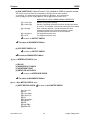
Diagnostics Quick Reference ............................................................................................................................. 5-2
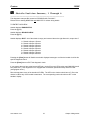
Test Site Sensors, 0 Through 7 ........................................................................................................................................ 5-6
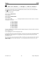
Shuttle Position Sensors, 1 Through 8 ............................................................................................................................. 5-7
Tube Full Sensors, 1 Through 8 (Lead-In Sensors) ......................................................................................................... 5-8
Tube Switch, 1 Through 8................................................................................................................................................ 5-9
Solenoid Check .............................................................................................................................................................. 5-10
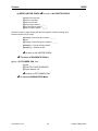
INTERFACE CHECK: RS-232 Check (Control Panel Check) ..................................................................................... 5-11
INTERFACE CHECK: Output Port (Output Cover LED Check) .............................................................................. 5-12
INTERFACE CHECK: Input Sort Check ...................................................................................................................... 5-13
ALL MOTOR CHECK: Shuttle Motor Check............................................................................................................... 5-14
ALL MOTOR CHECK: Test Site Plunger Motor “Z-Motor” Check ............................................................................ 5-15
ALL MOTOR CHECK: Octoloader Motor Check ........................................................................................................ 5-16
OCTO/INDEX CHECK: Shuttle Solenoid Check ......................................................................................................... 5-17
OCTO/INDEX CHECK: Input Sensor Check .............................................................................................................. 5-18
MODIFIED AUTOMATIC Z ADJUST FEATURE ......................................................................................................... 5-19
AUTOMATIC Z ADJUST QUICK REFERENCE ........................................................................................................... 5-21
CHAPTER 6
DISPLAY DICTIONARY ....................................................................................................... 6-1
MODEL 3000B HANDLER STATUS AND ERROR MESSAGES ..................................................................................... 6-1
CHAPTER 7
PREVENTIVE MAINTENANCE .......................................................................................... 7-1
OVERVIEW .............................................................................................................................................................. 7-1
GENERAL SOLENOID MAINTENANCE GUIDELINES ................................................................................................... 7-8
AIR REGULATOR MAINTENANCE GUIDELINES......................................................................................................... 7-9
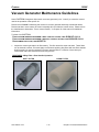
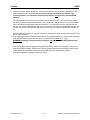
VACUUM GENERATOR MAINTENANCE GUIDELINES.............................................................................................. 7-12
PARTICLE INTERCONNECT CONTACT MAINTENANCE ..................................................................... 7-16
WHY CLEAN P I CONTACTS?................................................................................................................................... 7-16
P I CLEANING/PREVENTIVE MAINTENANCE PROCEDURE................................................................ 7-16
PREPARATION - DISMANTLING THE P I CONTACT ASSEMBLY:..................................................................... 7-16
ULTRASONIC P I CLEANING.................................................................................................................................... 7-17
www.exatron.com
ii
TOC
Exatron
CHAPTER 8
3000B
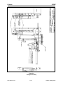
DRAWINGS ............................................................................................................................. 8-1
MECHANICAL ..................................................................................................................................................... 8-1
ELECTRICAL ....................................................................................................................................................... 8-1
CHAPTER 9
REPLACEMENT PARTS ...................................................................................................... 9-1
OVERVIEW .............................................................................................................................................................. 9-1
CHAPTER 10
SUPPLEMENT ...................................................................................................................... 10-1
PARTS LISTS ..................................................................................................................................................... 10-1
Overview.......................................................................................................................................................... 10-1
www.exatron.com
iii
TOC
Exatron
www.exatron.com
3000B
iv
TOC
Exatron
3000B
Chapter 1
Introduction
This user's guide provides installation, operation and maintenance information for all 3000B Series
Handlers. The EXATRON Model 3000B Handler is a tube to tube, gravity feed, eight-sort handler designed
for a wide variety of package types ~ both surface mount and through-hole technologies ~ using Snap-On
Changeover Kits to convert from one device size to another.
Model 3000B Overview
____________________________________________________________________________
EXATRON'S Model 3000B Series of automatic component handlers integrates customer-specified ambient
temperature programming/test sites, elevated temperature soak tracks and up to eight automatic device
inputs and outputs. The EXATRON Model 3000B retains the best features of the original Model 3000
(including compatibility with most older 3000 Series Changeover Kits) and incorporates many
technological advances developed from the Series 5000 Production Handling Systems. The improved
performance, reduced size, and classic flat-back bench-top style of the Model 3000B provide the ideal
solution for medium to high volume automated test and programming applications.
Blank/untested devices are loaded in tubes at the top of the handler then indexed to a test contact
mechanism. Among the standard choices, the customer may select special SMD (Surface Mount Device)
test sites which plunge the Device Under Test (DUT) up to 1.5 inches past the back of the handler to a
load board. Programming and testing take place here, using any of several types of programmers and
testers. The devices are sorted by "Pass" and "Fail" categories after each test. After testing, failed
devices are sorted into reject tubes. Devices which pass the test stage are sorted to the output tubes for
retrieval by the operator.
Many options are available for the Model 3000B Handler, most of which may be added in the field.
Available options are described in detail at the time of equipment price quote and include:
• 1 Track Hot Rail
• Upgrade to Automatic Print and Apply Labeler
• High Frequency Particle Interconnect Contact Sets
• Extruded Aluminum Output Tubes
• Output Tube Guard
• "Live Bug" or "Dead Bug" Operation (Available in most cases)
• Bowl-feed Input
• Output Tape and Reel
• Free-Rolling EXATRON Dolly ("FRED")
• Opto-Isolation Interface
• Status Light Pole
• Extended Warranties
• Service Contracts
Other Options Available as Requested
The Model 3000B handler operation is constantly monitored by its STD Bus CPU. Once a device enters
the handler, it is tracked by sensors as it passes through every step until it is positively placed in the
correct output tube. If a device jam should occur, an appropriate error message will be displayed on the
handler controller's front panel microterminal. Most jams may be cleared by pressing the [RUN] or
[Clear] buttons on the front panel.
www.exatron.com
1-1
Chapter 1 Introduction
Exatron
3000B
The handler may be operated in either of two modes: AUTO or MANUAL. MANUAL operation allows for
Handler Diagnostics sequences to be run, Handler Set-Up changes to be entered, and mechanical
adjustments to be made at the operator's convenience before, during, and after automatic Handler
operation.
AUTO operation continuously cycles devices through the handler. The handler will stop when empty but
re-start automatically when more devices are loaded. Each output tube may be filled to any pre-set
amount, with individual counters keeping track of quantities in all outputs. When an output tube fills, the
handler automatically begins to fill any other unfilled tube assigned to the sort signal received from the
tester. When all output tubes are filled, the handler will stop and a message will be displayed, such as,
ALL OUTPUTS FULL. The tube counter is automatically reset by removing the full tube and re-inserting
an empty tube. The handler will not cycle devices to outputs which have no tubes or which are full.
Additionally, a continuous subtotal count is maintained for each output, up to a total of 999,999 devices.
Sorting is accomplished by use of a stepper motor and a solenoid released shuttle. Dual positive binning
sensors keep track of the shuttle's position at all times. In the event of a sorting problem, a message will
be displayed on the handler's front panel, and the device will not be binned until the problem is corrected.
The Model 3000B Handler, like all EXATRON handlers, is guaranteed to properly bin every device even
during "power down" conditions. EXATRON has been one of the pioneers in the area of positive binning
functions. EXATRON test handling equipment meets or exceeds the standards set by MOTOROLA "Six
Sigma" binning requirements.
Model 3000B Handlers may be configured for all of the following packages:
-DIP, Dual In-Line Packages:
"Live Bug" or "Dead Bug" 0.300", 0.400", 0.600", 0.900" Body Width,
8 to 48 Pins, Standard Range
4 to 64 Pins, Optional Range
0.070" or 0.100" Pitch Leads
-SOIC, Small Outline Integrated Circuits: "Live Bug" or "Dead Bug" 0.150",
-SOJ,"J" Lead Shape:
0.170", 0.210", 0.300", 0.330", 0.350", 0.450" Body Width;
0.100", 0.079", 0.050", 0.039", 0.025", 0.020" Pitch Leads
-PLCC, Plastic, Leaded Chip Carriers:
18, 20, 24, 28, 32, 44, 52, 68, 84 Pin PLCCs, "Live Bug" only.
-LCC, Leadless Chip Carriers:
18, 20, 24, 28, 32, 44, 52, 68, 84 Pad LCCs, "Live Bug" only.
-SIP; SIL, Single In-Line Packages:
D-Pak, D2-Pak, D3-Pak, TO-218, TO-220, TO-247, TO-3P,
TO-3PBL, DO-214, SOT23
Custom Hybrid SIPs, Others
-TSSOP
-Small Printed Circuit Boards
- ZIP, Staggered Lead Form Single In-Line Package
-SIMM, Single In-Line Memory Modules
-Other Memory Modules
-Numerous Custom Devices
www.exatron.com
1-2
Chapter 1 Introduction
Exatron
3000B
Exatron Support Services
Toll-Free Telephone Customer Service Line
For factory technical support, call 1-800-EXA-TRON, between 8:00 A.M. and 5:00 P.M. Pacific time,
Monday through Friday. When calling, please have your EXATRON equipment close at hand, along with
the following information:
z
z
z
The exact wording of any messages that appeared on your handler display.
A description of what happened and what you were doing when the problem occurred.
A description of how you tried to solve the problem.
Standard Warranty
All EXATRON products are under warranty for one year from the date of purchase. EXATRON agrees to
repair any mechanical or electrical assembly, subassembly, or entire unit which fails during normal use
within its first year. The Customer agrees to follow the recommended maintenance procedure as defined
in the User's Manual.
EXATRON DOES NOT warrant test contactors. Handler test contactors are fragile and may be easily
ruined by operator abuse. EXATRON uses the finest materials available in our contactor designs.
All warranty work must be performed at the EXATRON factory or at an authorized Representative Service
location. As described on the following page, in-house service by our customers is encouraged.
EXATRON does not warrant the following:
1. Damage caused by improper packaging of equipment returned to EXATRON for repair.
2. Damage caused by the freight forwarder.
3. Damage caused by acts of God: flood, fire, earthquake, etc.
4. Damage caused by equipment connected to improper power line voltages.
5. Operator abuse.
6. Interface hardware not manufactured by EXATRON.
7. Test contactors.
8. Damage caused by equipment connected to improper air supply: contaminated with oil, water,
dirt, etc.
Customer In-House Service
Except in the case of Laser Marking Systems, EXATRON encourages customer in-house equipment
service and tries to make in-house service as easy as possible to perform. There are no "Void Warranty"
warning stickers on EXATRON handlers. EXATRON will even honor the warranty on a unit when an in-house
repair attempt leads to further damage to the unit. By using the built-in diagnostic software and diagnostic
tools, it is usually possible for the operator to isolate a problem quickly and effect a repair.
www.exatron.com
1-3
Chapter 1 Introduction
Exatron
3000B
Offshore Warranty Service
An EXATRON Handler purchased in the United States and then shipped offshore will be warranted through
EXATRON in California. Replacement parts are furnished for a period of one year from date of purchase
with the exception of replacement contactors. In most cases, it will not be necessary to return the worn
part from the offshore user location.
To receive offshore service support, the handler must be purchased through your local EXATRON
Representative or an extended warranty agreement must be purchased directly from your local EXATRON
Representative.
Please supply the following information when requesting offshore service or replacement parts:
1. The part number(s) required. If the part number is not known, photocopy the part and fax it to
EXATRON.
2. The Model number of the Handler.
3. The type of device being run by the Handler, such as: DIP, SOIC, SOJ, PLCC, LCC, SIP,
PGA, PCB, ZIP, etc.
4. The Handler's serial number.
5. The full shipping address.
6. Any special shipping or customs instructions.
7. Method of shipment, such as: Federal Express, UPS, DHL, U.S. Mail, or the name of your
chosen freight forwarder.
In most cases, faxed requests and shipment of replacement parts orders are processed within twenty-four
hours of receipt by EXATRON.
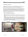
The Model 3000B
with Eight Automatic Inputs
EXATRON'S eight-tube Octoloader is an ambient automatic eight-tube loader. The standard Model 3000B
comes equipped with this octoloader which is a moving metal plate holding up to eight tubes of devices,
controlled by the handler's CPU by means of a stepper motor. The plate automatically moves both left
and right, positioning each tube of devices over the handler input track. When the input track is emptied,
the octoloader automatically searches for tubes with devices. The octoloader has a sensor mounted at its
junction with the input track. The octoloader can "see" a device jam and stop its own movement to
prevent breaking the jammed device. The octoloader also has an automatic "wiggle" jam-clearing
operation which it will implement immediately in an effort to remove the jam without operator assistance.
Model 3000B octoloaders use a Snap-On plate which is specifically fitted with tube holders for a given
device application.
All Model 3000B Handlers not intended to be used on a "FRED," (Free Rolling EXATRON Dolly) are
supplied with bench-top base plates which must be bolted directly to a bench or table top to secure the
handler. Each plate includes two sets of tilt bars which enable the handler's tilt angle to be altered for
specific applications. The tilt angle is critical for ceramic DIPs and LCCs since too much drop angle may
cause chipping of the packages.
www.exatron.com
1-4
Chapter 1 Introduction
Exatron
3000B
The Model 3010B
with One Elevated Temperature Track
The Model 3010B Hot Rail adds a single track hot rail to the input of the handler. This track holds twenty
inches of devices in order to preheat them prior to test. The temperature range of the Hot Rail is ambient
to +125° C. AC heaters are located within the Hot Rail. Exceptional temperature control is maintained by
constantly monitoring four points in the Rail and four points in the Test Site. The guaranteed accuracy is
±3° C everywhere in the Soak Rail and ±2° C in the Test Site. All four "zones" in the hot rail are controlled
by an EXATRON-designed computerized temperature controller.
The input of the Hot Rail has a manually operated two-input tube holder assembly.
All Model 3010B Handlers are supplied with a Free Rolling EXATRON Dolly ("FRED.") For operation, the
handler is to be mounted onto this floor stand which has four large tires for easy positioning and four floor
jacks to lock it into place.
Also Available From Exatron:
The Model 2000B
with Two-Tube Manual Input
The Model 2000B is an ambient handler with a manually operated two-input tube holder assembly for low
to mid-volume handling applications. The tube holder must be manually shifted when one tube of devices
empties in order to present another tube of devices to the input track. The Model 2000B uses Snap On
Change Over Kits to accommodate various size packages. The tube holders are custom-machined to a
specific tube size and are included as standard equipment with Model 2000B Snap On Change Over Kits.
All Model 2000B Handlers are supplied with bench-top base plates which must be bolted directly to a
bench or table top to secure the handler. Although smaller and less expensive than our Model 3000B, the
2000B Series handlers are equipped with a broad range of features found in all EXATRON handlers
including:
• Wide Variety of Device Handling Capability
• Quick Changeovers Using Modified Snap-On Change Kits
• Variety of Interfaces
• Positive Binning
• Plunge to Board Test Contact Mechanism
• ESD Safeguards
The Model 5000
Series of Production Handling Systems
The 5000 Series of production handlers integrate any combination of customer-specified ambient
temperature programming/test sites, hot chamber(s), elevated temperature test site(s) and a "smart" laser
marking system. In addition, automatic tube loader/reloader components from various manufacturers may
be integrated into EXATRON'S Model 5000 when the laser marking system option is specified.
When equipped with a laser marker, the entire system is controlled by a single 80486/33 computer.
One or more test sites are available on all of the various Model 5000 configurations. The EXATRON
Model 5000 Series of Heavy-Duty Handling Systems are ideal for automating high-volume program, test,
and mark applications.
www.exatron.com
1-5
Chapter 1 Introduction
Exatron
3000B
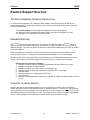
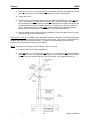
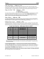
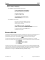
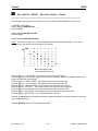
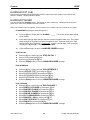
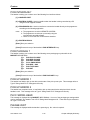
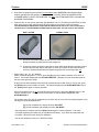
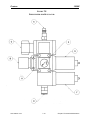
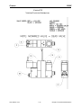
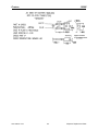
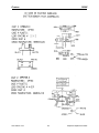
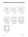
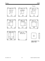
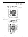
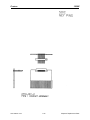
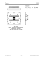
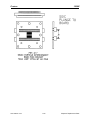
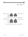
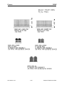
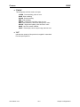
FIGURE 1-1
A. OCTOLAODER MOTOR.
B. TILT MECHANISM.
C. AIR REGULATOR.
D. SERIES 3000B REMOTE POWER SUPPLY.
E. BASE PLATE. Please refer to drawing #3000-215 for base plate bolt-down hole pattern.
ALL BENCHTOP HANDLERS MUST BE SECURELY BOLTED TO THE TOP OF THE WORKBENCH.
F. TEST HEAD DOCKING BLOCK.
G. SHUTTLE STEPPER MOTOR.
H. HANDLER PORT INTERFACE.
I.
OCTOLOADER SIDE BEARING BLOCK.
J.
RS-232 INTERFACE PORT.
K. FRONT PANEL CONTROL.
L. LEFT HAND OCTOLOADER STOP ADJUST BLOCK.
M. OCTOLOADER CHAIN TENSION ADJUST BLOCK.
N. OPTIONAL AIR QUICK DISCONNECT.
O. OCTOLOADER GUIDE BAR.
P. SHUTTLE CHAIN TENSION ADJUST BLOCK.
Q. TEST HEAD MOUNTING BOLT-DOWN HOLE PATTERN.
R. RIGHT HAND OCTOLOADER STOP ADJUST BLOCK.
S. CHANGEOVER KIT INPUT / OUTPUT PORTS.
T. SHUTTLE ASSEMBLY. Standard PLCC shuttle assembly shown.
www.exatron.com
1-6
Chapter 1 Introduction
Exatron
3000B
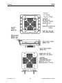
FIGURE 1-1
www.exatron.com
1-7
Chapter 1 Introduction
Exatron
3000B
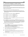
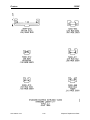
Warning/Caution Labels
YOUR NEW EXATRON HANDLER WILL ARRIVE WITH SOME OR ALL OF THE FOLLOWING WARNING LABELS ATTACHED:
EXATRON
PART NUMBER
LABEL TEXT
LAB03-001
DANGER - INVISIBLE LASER RADIATION WHEN OPEN ...
LAB03-004
DANGER - ELECTRICAL HAZARD
LAB03-006
CAUTION - DO NOT OPERATE WITHOUT GUARDS ...
LAB03-007
DANGER - WATCH YOUR HANDS AND FINGERS
LAB03-008
CAUTION - BEFORE CLEANING OR SERVICING ...
LAB06-001
CAUTION - HIGH TEMPERATURE
LAB09-001
THIS UNIT SOLD AND SERVICED BY ...
LAB09-002
WARNING! DON'T REMOVE WITH HANDLER POWER ON
(IN-HOUSE ONLY)
THIS ORDER CONTAINS PARTICLE INTERCONNECT ...
5000-494
DANGER - DO NOT REMOVE OR DETACH ...
5000-958
CAUTION - HIGH PRESSURE AIR SOURCE
5000-967
CAUTION - CONTAINS HOT SURFACES
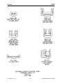
Availability of Warning Labels:
Current laws pertaining to the cautionary labels required to be installed on electronic equipment vary from
state to state. EXATRON makes every attempt to comply with all known labeling laws and safety
considerations as they relate to our component handling systems. In effect, virtually every surface of the
handler could be covered with warning signs and labels. For aesthetic reasons, we choose to produce a
machine with a less cluttered appearance, while still providing adequate visual caution indicators.
Individual customers may wish to obtain additional labels to facilitate safe operation and service for this or
other electronic equipment in use at their locations. The labels listed above are shown in detail on the
following pages and may be purchased from the EXATRON factory as desired. Our toll-free telephone
number is 1-800-EXA-TRON.
www.exatron.com
1-8
Chapter 1 Introduction
Exatron
www.exatron.com
3000B
1-9
Chapter 1 Introduction
Exatron
www.exatron.com
3000B
1-10
Chapter 1 Introduction
Exatron
www.exatron.com
3000B
1-11
Chapter 1 Introduction
Exatron
www.exatron.com
3000B
1-12
Chapter 1 Introduction
Exatron
www.exatron.com
3000B
1-13
Chapter 1 Introduction
Exatron
www.exatron.com
3000B
1-14
Chapter 1 Introduction
Exatron
www.exatron.com
3000B
1-15
Chapter 1 Introduction
Exatron
www.exatron.com
3000B
1-16
Chapter 1 Introduction
Exatron
www.exatron.com
3000B
1-17
Chapter 1 Introduction
Exatron
www.exatron.com
3000B
1-18
Chapter 1 Introduction
Exatron
www.exatron.com
3000B
1-19
Chapter 1 Introduction
Exatron
www.exatron.com
3000B
1-20
Chapter 1 Introduction
Exatron
3000B
Chapter 2
Installation
Basic installation of your new Exatron handler will consist of the following three major steps:
I. Unpacking the handling equipment and assembling its peripheral parts.
II. Powering up the handler and running Diagnostics sequences.
III. Cycling sample tubes of devices.
These multi-part steps are described in detail below. After these steps are completed you will be ready to
interface the handler to your tester/prom programmer as described in chapter 3, interface information.
Please read and understand this entire User's Manual before installing or using your Exatron
handler. The following safety procedures must be followed at all times.
Exatron Safety Features
____________________________________________________________________________
Electrical Hazards
High Voltage Testing Applications: It is the policy of Exatron to determine the precise application for
every handler we make prior to shipment. In some cases, the handler will be used to test devices at high
voltages. If your handler will be used to test devices with voltages in excess of 80 VDC or 80 VAC, the
handler will need to be equipped with safety covers.
If Exatron is notified of high voltage requirements as described above on the written purchase order at the
time of order placement, we will equip your handler with safety covers having electrical interlock switches.
These switches are intended to be utilized by the operator by connecting them to the customer-supplied
tester. When the interlock switch is open, the tester will be shut down with no possibility of high voltage at
the handler's contacts. All safety hardware should be verified for proper operation by the customer's own
in-house safety officer.
If you intend to use this handler for high voltage testing, notify Exatron immediately and place an order for
safety covers, if this has not already been done. Added safety covers will be provided at additional cost to
the user.
If your Exatron handler is equipped with safety covers, never operate the handler without them. Never
remove the safety covers. Never defeat any electrical interlock switch supplied with the handler.
High Internal Voltages: In most cases, there are no high voltages used inside the Model 3000B handler
electronics -- with the exception of the Model 3010B Hot Rail.
High voltage from the building line current is present in the Exatron remote 3000B power supply. Only
qualified service technicians should do any repair work on the power supply. Make sure to use qualified
service technicians when attempting to repair any portion of the handler that uses high electrical voltages.
www.exatron.com
2-1
Chapter 2 Installation
Exatron
3000B
Compressed Air
Your Exatron handler may require a compressed air supply. If your specific changeover kit requires
compressed air, connect the handler to an 80 PSI (+/- 3PSI) air source. Please refer to the "Air
Requirements" section of the Model 3000B General Operating Specifications for further details.
Using compressed air can be hazardous. It is the responsibility of the customer to properly train all
handler operators in every aspect of the safety practices associated with the use of compressed air.
NEVER operate any Exatron equipment which requires compressed air without an approved air
regulator and shutoff valve.
Moving Parts
Most moving parts of the Model 3000B handler have structural covers. NEVER OPERATE THE
HANDLER WITH ANY COVER REMOVED. Be careful to keep your fingers away from any moving parts
on the handler. Keep all loose-fitting clothing away from moving parts, as well. Do not attempt to service
the handler in any way when any part of the handler is in motion. Use the [PAUSE] button on the handler
controller to stop the handler's operation, or turn the handler off before attempting to access any moving
part of the handler.
Overall System Safety
Typically, the handler is simply one part of a complete test system. It is the responsibility of the user to
properly train all handler operators in all of the safety practices required for every component of the test
system.
Unpacking, Assembling
Your Model 3000B handler has been shipped to you in specially designed containers which should be
safely stored away. If it should become necessary to return the handler to Exatron, these original shipping
containers must be used. Exatron assumes no responsibility for damage during return shipment caused
by improper packing of the handler. If the shipping cartons become misplaced or damaged, new shipping
cartons may be ordered from Exatron.
UNPACKING AMBIENT HANDLERS: MODEL 3000B
Tools required:
One standard flat-bladed screwdriver
One Phillips head screwdriver
1. Open the box with the "DELICATE INSTRUMENT" label side up and remove the top
"honeycomb" cardboard cushion panel. You will see a sealed cardboard carton surrounded on all
four sides by cardboard cushion panels. Inside the internal carton, the handler is bolted to a wooden
base held in place for shipping by the internal carton which has no bottom. Cut or remove the sealing
tape on the top of the internal carton.
2.
Remove this internal carton by pulling straight up on its sides. You can now see the handler
bolted to the wooden base. The handler and the wooden base weigh approximately forty-five pounds.
3. Firmly grasp the handler on each side and lift straight up. Set the handler on a sturdy bench or
table top.
4. Unscrew the bolts to remove the wooden base from the handler.
www.exatron.com
2-2
Chapter 2 Installation
Exatron
3000B
5. Save the bolts and their washers with the wooden base and return them to the shipping
container.
6. Replace the internal carton and the top cushion panel.
7. Carefully examine the space between the container and the four side cushion panels for any
additional parts since Tube Holder extensions and sample devices are often packed in these
spaces.
8. Replace all packing material and internal boxes. The shipping carton should now be ready for
storage - DO NOT DISCARD! If it becomes necessary to return this handler to Exatron, use this
shipping container and re-pack the handler in the reverse order of the unpacking procedure described
above.
UNPACKING THE POWER SUPPLY
The power supply is shipped in a separate 20" x 18" x 18" cardboard box.
Open the box with the "DELICATE INSTRUMENT" label side up and remove the top internal box
containing handler peripherals, such as: Octoloader Plate, Air Regulator, Shuttle, User's Manual
and Power Cords. Set these items aside.
Open the bottom internal box and remove the power supply using both hands. Set the power
supply aside and return the packing material to the empty box. The shipping carton should now be ready
for storage - DO NOT DISCARD! Proceed with the unpacking/assembly instructions. If you have not
purchased a Free Rolling Exatron Dolly, or FRED, skip the following step.
UNPACKING THE FRED/AMBIENT ASSEMBLY
Tools required:
www.exatron.com
One standard flat-bladed screwdriver
One Phillips head screwdriver
Size 6 Allen wrench
2-3
Chapter 2 Installation
Exatron
3000B
Open the fred shipping box and remove all parts of the metal fred. Inside the box you will find one
additional set of FRED assembly instructions, Detail Figures A, B and C, and one FRED parts list.
Assemble the base of the FRED first. Refer to Detail A.
www.exatron.com
2-4
Chapter 2 Installation
Exatron
3000B
1. Using six #1/4 - 20 x 1.75" long bolts and six lock washers, attach the two uprights to the base
plate. Note the location of the small holes in the base in relation to the uprights.
2. Tighten all six bolts.
3. Locate the two riser bars (#3000-041) and the rigid support bar (#3000-034.) Using four #1/4
- 20 x 2.75" long bolts, four block washers and four #1/4 - 20 hex nuts, attach the risers and
the rigid support bar to the uprights by inserting the bolts through the upright, through the riser
and then through the holes in the rigid support bar. The large holes in the riser should be at
the top. Assemble the riser bar in the lowest position initially and then adjust its height as
needed. Place lock washers and nuts on all bolts. Do not tighten the bolts yet.
4. Place the handler power supply on the base (#3000-032.) Insert the rubber feet on the power
supply into the pre-cut holes in the base.
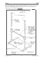
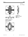
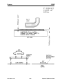
Please refer to Figure B. The FRED may be assembled with either of two different pivot points depending
upon your application. The hardware remains the same in both cases. Type A pivot is recommended for
handlers using cable-type test contact interface. Type B pivot is recommended for zero test head
interfaces, or when docking the handler to a manipulator.
NOTE: The maximum slide angle for PLCC devices is 45° from vertical.
1. Locate the two blue pivot plates (#3000-035.)
2. Using two #3/8 x 16 x 2.75" long bolts, four #3/8 x 16 x 1.75" long bolts, six #3/8 lock washers
and six #3/8 x 16 hex nuts, attach the pivot plates to the riser bars according to the pivot point
selected. Place lock washers and nuts on all six #3/8 bolts. Do not tighten the bolts yet.
www.exatron.com
2-5
Chapter 2 Installation
Exatron
3000B
Please refer to Figure C.
3. Locate the two plate hanger blocks (#3000-037.)
4. Using two #1/4 x 20 x1.50" long bolts and two lock washers, mount the plate hanger blocks
onto the frame, threaded end up. These holes are marked "G" on FRED detail Figure C. Do
not tighten the bolts yet.
5. Remove the handler main plate (#3000-301) from the base plate (#3000-216). Remove the
hinges and the tilt blocks.
6. Using two #1/4 x 20 x .62" long bolts and two lock washers, bolt the handler to the plate
hanger blocks on the frame through the holes marked "G" on FRED detail Figure C.
7. Using four #1/4 x 20 x 1.37" long bolts and four lock washers, bolt the handler main plate to
the frame through the four tapped holes on the main plate also used by the base plate hinges.
These holes are marked "E" on FRED detail Figure C.
8. Verify that the slide angle and handler height are correct for your application then, tighten all
bolts on the frame, risers, rigid support bars and uprights.
9. TRAY OPTION: Using three #1/4 x 20 x 2.50" long bolts, three lock washers and three #1/4 x
20 hex nuts, bolt the tray extension frame to the bottom edge of the FRED frame. Tighten all
three bolts.
DETAIL C
www.exatron.com
2-6
Chapter 2 Installation
Exatron
3000B
UNPACKING HOT RAIL HANDLERS: MODEL 3010B
Tools required:
One standard flat-bladed screwdriver
One Phillips head screwdriver
The Model 3010B Hot Rail is shipped in at least three boxes. The largest box, 46" x 23" x 32" contains the
handler/hot rail as an assembled unit. The FRED box is 5" x 33" x 24" and contains the Free Rolling
Exatron Dolly frame. The third box, 20" x 18" x 18", contains two power supplies. A fourth box may be
included in your shipment containing spare parts or additional handler options. Open these boxes in the
order listed below so that loose parts do not become mixed or misplaced.
UNPACKING THE POWER SUPPLY
The power supply is shipped in a separate 20" x 18" x 18" cardboard box.
Open the box with the "DELICATE INSTRUMENT" label side up and remove the top internal box
containing handler peripherals, such as: Octoloader Plate, Air Regulator, Shuttle, User's Manual and
Power Cords. Set these items aside.
Open the bottom internal box and remove the power supply using both hands. Set the power
supply aside and return the packing material to the empty box. The shipping carton should now be ready
for storage - DO NOT DISCARD! Proceed with the unpacking/assembly instructions.
UNPACKING THE FRED/ENVIRONMENTAL ASSEMBLY
Tools required:
One standard flat-bladed screwdriver
One Phillips head screwdriver
Size 6 Allen wrench
Open the fred shipping box and remove all parts of the metal fred. Inside the box you will find one
additional set of FRED assembly instructions, Detail Figures A, B and C, and one FRED parts list.
Assemble the base of the FRED first. Refer to Figure A.
1. Using six #1/4 - 20 x 1.75" long bolts and six lock washers, attach the two uprights to
the base plate. Note the location of the small holes in the base in relation to the
uprights.
2. Tighten all six bolts.
3. Locate the two riser bars (#3000-041) and the rigid support bar (#3000-034.) Using
four #1/4 - 20 x 2.75" long bolts, four block washers and four #1/4 - 20 hex nuts,
attach the risers and the rigid support bar to the uprights by inserting the bolts through
the upright, through the riser and then through the holes in the rigid support bar. The
large holes in the riser should be at the top. Assemble the riser bar in the lowest
position initially and then adjust its height as needed. place lock washers and nuts on
all bolts. Do not tighten the bolts yet.
4. Place the handler power supply on the base (#3000-032.) Insert the rubber feet on
the power supply into the pre-cut holes in the base.
Please refer to Figure B. The FRED may be assembled with either of two different pivot points depending
upon your application. The hardware remains the same in both cases. Type A pivot is recommended for
handlers using cable-type test contact interface. Type B pivot is recommended for zero test head
interfaces, or when docking the handler to a manipulator.
NOTE: The maximum slide angle for PLCC devices is 45° from vertical.
www.exatron.com
2-7
Chapter 2 Installation
Exatron
3000B
5. Locate the two blue pivot plates (#3000-035.)
6. Locate two #3/8 x 16 x 2.75" long bolts, four #3/8 x 16 x 1.75" long bolts, six #3/8 lock
washers and six #3/8 x 16 hex nuts.
7. Place the #3/8 x 16 bolts and pivot plates on the risers. push the bolts in just far
enough to hold this assembly together and still leave room for the handler frame to be
placed inside. The bolts can then be pushed quickly into the handler frame while it is
held in position.
8. Handlers with Hot Rails are shipped pre-assembled on their FRED frames.
UNPACKING THE HOT RAIL HANDLER ASSEMBLY
Open the large handler box with the "DELICATE INSTRUMENT" label side up by carefully removing the
two reusable straps on the box. There is no need to cut any tape or remove any staples. lift the top of the
box straight up and remove the inner protective packaging assembly. You should now be able to see the
handler. The handler assembly is very heavy and will require two people to unpack it. With one person at
each end of the unit, pick the handler assembly straight up out of the box.
1. With two people holding the handler frame assembly by its sides and a third person
ready to push the bolts into place, position the handler assembly horizontally at the
long pivot bolts. Push those pivot bolts into the frame on each side of the handler.
2. With both people still holding the handler frame assembly by its sides, tilt the handler
to the desired tilt angle and push the remaining four shorter bolts into place. The two
people holding the handler frame should not let go of the handler until all six bolts are
properly inserted.
3. Double-check that the FRED is properly assembled and verify that the tilt angle is
correct. After you have confirmed the assembly is satisfactory, tighten all the bolts.
4. TRAY OPTION: Using three #1/4 x 20 x 2.50" long bolts, three lock washers and
three #1/4 x 20 hex nuts, bolt the tray extension frame to the bottom edge of the
FRED frame. Tighten all three bolts.
www.exatron.com
2-8
Chapter 2 Installation
Exatron
3000B
General Operating Specifications
Electrical Requirements
Handlers shipped either within the United States or off-shore have built-in electrical supply
capability for 100VAC to 240VAC, 50Hz to 60Hz, except in the case of the Model 3010B Hot Rail.
The Hot Rail thermocouple card contains either a 50Hz crystal or 60 Hz crystal, which must be
specified by the customer.
Model 3010B Hot Rails operating at 240 VAC require an optional step-down transformer for the
handler's heaters.
Connect the power cord to earth-grounded power outlets only.
If the handler is to be used in an electrically noisy environment or near large electromechanical
equipment, Exatron recommends the use of a reliable power conditioner to filter line noise,
surges, and spikes which can cause the handler to operate improperly or become damaged.
Ambient handlers require 3 Amps at 110 VAC. Handlers with Hot Rails require 7 Amps at 110
VAC.
Electricity supplied to the handler must be within the specified operating ranges. If the line voltage drops
too low, the handler may not function properly or may be seriously damaged. Verify that correct operating
line voltage is present. If it is not, contact Exatron for assistance.
SERVICE CALLS MADE TO THE CUSTOMER FACILITY TO CORRECT PROBLEMS CAUSED BY
IMPROPER ELECTRICAL SUPPLY ARE NOT COVERED BY THE EXATRON WARRANTY.
Air Requirements
Depending upon the type of Changeover Kit used, the Model 3000B may require a filtered air
pressure supply of 80 psi/5 cfm (+/- 3 PSI). This air supply must be Clean: containing no
particulate matter greater than 5 microns in size; Dry: having a dew point of 36° F to 38° F; and
free of any oil. To maintain these levels of pressurized air quality, replace the coalescing air filter
(Exatron part #GPA-97-075) in the air regulator of your handler after every 6000 hours or 12
months of operation, whichever comes first; or if your air regulator registers a pressure drop of 15
psi.
Moisture of any kind will travel through external and internal air lines. This moisture will coat these
air lines and the insides of the handler's cylinders, causing them to stick or to stop functioning
altogether. The best defense against this kind of contaminate is to prevent it from occurring in the
first place by maintaining the clean air supply described above.
If the air lines are allowed to become discolored or the moisture traps become overfilled, damage
to the system will occur. The only corrective action to take at that point is to replace all of the air
lines and to completely clean all of the solenoids supplied by those air lines. Handler damage
due to improper air supply is not covered by the Exatron warranty.
House/Shop vacuum is not required. Changeover kit vacuum requirements are supplied by builtin venturi vacuum generators.
www.exatron.com
2-9
Chapter 2 Installation
Exatron
3000B
Environmental Operating Specifications
Location
ALL "BENCHTOP" (ALSO KNOWN AS "TABLE TOP," "PLATE MOUNTED") HANDLERS MUST BE
BOLTED SECURELY TO THE TOP OF THE BENCH. The handler's center of gravity is fairly high in
relation to the benchtop. This makes the handler unstable if not bolted down, which could result in the
handler being knocked over. This can cause serious damage to the handler and injury to the user.
This machine should be installed in a dust-free environment to preclude dust and dirt particles from
contaminating its moving parts, especially those parts which come into contact with the devices being
tested. The life of your handler is greatly enhanced by keeping it as clean as possible.
This Model 3000B handler should be placed as close as possible to your tester test socket, since cable
length from the contactor to the tester is critical in most applications. Please refer to Chapter 3 Interface
Information, for further details.
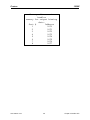
As specified in the table shown below, Exatron handlers are designed to withstand the impact of virtually
any climate and/or environment that they may be used in. Periodic maintenance as prescribed in Chapter
7 of this manual will ensure that emergency "down time" is kept to a minimum.
Temperature
Relative Humidity
Handler/Hot Rail
Handler with Printer
40° to 115° F,
5° to 45° C
20% to 85%, Noncondensing
40° to 105° F,
5° to 40° C
20% to 80%, Noncondensing
Airborne dust and moisture, if present, will naturally settle on all surfaces of your handler. If allowed to
build up, dust can eventually block sensors, clog solenoids, fill up the filters of cooling fans, vacuum
generators, air filters and generally inhibit the smooth movement of devices through the handler.
The best defense against this kind of contaminate is to install and use your handler in a dust-free
environment to preclude dust and dirt particles from contaminating its moving parts, especially those parts
which come into contact with the devices being tested. If dust is a factor in your operating environment,
dust the handler off with blasts of compressed air at least every 8 hours. Make sure that the compressed
air is clean, dry and free of any oil.
ESD Grounding
All Model 3000B Handlers meet or exceed all known device manufacturers' ESD specifications. All 3000B
Series Handler chassis' are directly connected through the power supply to earth ground. All guide rails,
shuttles, tube holders, hot rails and output trays are connected to earth ground. The handler's power
supply ground is directly connected to earth ground. The handler power supply MUST be connected to a
properly grounded power outlet. NEVER operate the handler with the power line ground removed or
defeated.
All handler main plates, covers and non-trackwork handler parts are plated with conductive finishes.
Exatron uses a very limited quantity of anodizing finishes on handler surfaces.
www.exatron.com
2-10
Chapter 2 Installation
Exatron
3000B
DUT Materials
Device Under Test
Component packages vary in the materials from which they're made. The composition and size of
packages can cause wear on the parts of the handler with which they come into contact. Heavy, roughsurfaced DUTs will cause handler wear faster than lighter, smoother materials.
The best defense against the effects of the DUT material on a handler is to ensure that the handler is
properly adjusted for the package it is running. The height of the handler door over the DUT should be as
close as possible. The test site contacts should close on the DUT with enough pressure to provide good
electrical contact, but not press hard enough to force the DUT to the left or the right of the test site rail.
If you have any questions regarding handler adjustment issues, please contact the Exatron Customer
Service Department.
If your handler does experience high levels of wear due to device materials, this will generally occur at
specific points on the handler. If you wish, you may send worn-out equipment parts back to Exatron for
evaluation. In many cases, the excessive wear can be reduced by design changes or material/finish
changes. It is possible that the point which wears out can be modified into an insert which can be easily
replaced as required.
Tilt Mechanism - Table Top Mounting
A tilt mechanism is built into your Model 3000B table top handler. The slide angle may be adjusted from
12° to 60° from vertical. The tilt mechanism is easily removed as needed for large test head interfaces.
The Free Rolling Exatron Dolly (FRED) has its own built-in tilt mechanism.
The slide angle may need to be adjusted when large ceramic devices are to be tested. This is because
ceramic devices may chip or crack upon impact with other devices. Decreasing the slide angle increases
drag and slows the device down as it passes through the handler and into the output tube, which
minimizes chipping from impact. Depending upon the mass and shape of a specific ceramic device, the
angle may need to be reduced.
The handler cycle timing is sensor-controlled, so the cycle speed will be automatically slowed to match
that of the devices. The recommended angle for all plastic devices is 12° from vertical. The maximum
slide angle for PLCC devices is 45° from vertical.
NOTE: Ceramic device damage may be minimized by use of bumpers which attach directly to each
device. Some types of these bumpers will run through a standard Exatron handler. In some cases,
custom rails may be required.
www.exatron.com
2-11
Chapter 2 Installation
Exatron
3000B
Powering Up, Running Diagnostics
You may find it beneficial to contact your local Exatron Representative to assist you in setting up your
handler. If you prefer, please feel free to call the Exatron Customer Service Department for assistance as
needed during set up. Our toll-free telephone number is 1-800-EXA-TRON.
After you have unpacked and assembled the handler according to the instructions shown above,
review this entire user's manual before proceeding.
1. Bolt your "benchtop" Model 3000B handler securely to your workbench. If your Model 3000B handler
is mounted on a FRED, verify that it is secure; double-check all mounting bolts.
2. Compare your purchase order to the handler's packing slip and verify that all items ordered have been
received.
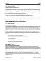
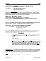
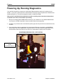
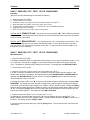
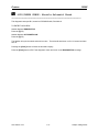
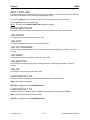
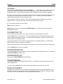
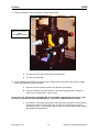
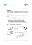
3. If your application requires compressed air, bolt the black Wilkerson air regulator, part #NCOD440
onto the right side of the 3000B frame, using two #10-32 x 5/8" bolts. With the orange switch in the
closed position, attach the nozzle of your clean, dry, compressed air supply to the air regulator.
WILKERSON AIR REGULATOR – OFF POSITION
Main Air Flow On/Off
Switch
(On Position Shown)
www.exatron.com
2-12
Chapter 2 Installation
Exatron
3000B
4. DO NOT PLUG THE HANDLER INTO THE POWER SUPPLY YET. First plug the power supply only
into a grounded wall outlet. Turn the power supply on by pressing the red power button and verify that
the +5 volts and +24 volts are operational. If you wish to check/calibrate the power supply output,
please refer to Chapter 7, Preventive Maintenance.
5. Turn the power supply off again. Now connect the handler power cord to the power supply via the
white Molex connector.
6. If your application requires it, turn the compressed air supply on. Turn the orange switch on the air
regulator to the on position.
7. Move the octoloader plate so that it is flush against the octoloader home switch. Hold the plate in this
position until the power is on.
8. Turn the handler power on by pressing the Red power button on the power supply and observe closely
the display on the handler controller microterminal.
NOTE: Power to the Model 3000B may be turned off and then on again at virtually any time during
handler operation. The only time it is not advisable to turn the power off is within the first 10 seconds
of turning the handler on.
First you will see VO1.01 Test Ok displayed, quickly followed by your handler model number and
firmware revision date. If you have a plunge-type test assembly, the next message to be displayed
will be JOG UP, which tells you that the Z plunger is moving up to locate its top position switch.
The next message displayed is MOD SET UP ? NO.
9. Press the [DIAGNOSTICS] button on the handler microterminal and perform the complete set of
Diagnostic Tests on your handler and included options. These Diagnostics procedures are detailed
for you in Chapter 5 of this manual. This is your opportunity to become familiar with the handler's
controller and mechanical functions as you observe its self-testing cycles.
www.exatron.com
2-13
Chapter 2 Installation
Exatron
3000B
Practice session: Cycling sample devices
1. Upon completion of all Handler Diagnostics sequences, turn the handler power off, then on again.
When the handler controller displays MOD SET UP ? NO, press the [SET UP] button to toggle this
message to MOD SET UP ? YS.
2. Make all necessary Set Up Modifications as detailed in Chapter 4, Handler Set Up.
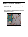
3. Locate a sample set of devices and tubes to use for practice.
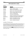
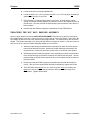
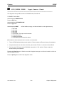
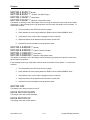
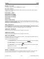
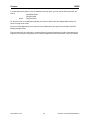
4. An Exatron LED Checker, part #3000-052, may be used as a simulator to run sample devices through
the handler. In this case, select the Handler Port Interface during Set Up Modification and switch the
Sort Select Pin 1 to the ON position. This will simulate the tester/programmer. A sort select of 1 will
force all parts cycled to binned to a PASS tube.
LED CHECKER
5. Run the sample devices until you are comfortable with the operation of the Model 3000B handler. You
are now ready to interface the handler to your tester or PROM programmer. Please refer to Chapter 3
Interface Information for details on communications interface selection.
www.exatron.com
2-14
Chapter 2 Installation
Exatron
3000B
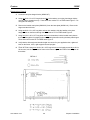
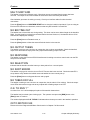
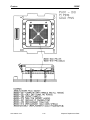
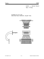
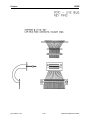
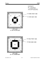
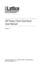
The Exatron Octoloader
EXATRON’S eight-tube capacity automatic tube loading mechanism, called the Octoloader, will
automatically load any device supplied in tubes into your EXATRON handling system. The Octoloader
assembly snaps onto the handler for easy conversion from one device size/type to another.
The Octoloader is a moving plate that holds tubes of devices and is controlled by the handler’s CPU via a
stepper motor. During production, the plate automatically moves from side to side, positioning each tube
above the handler input track. When the input track becomes empty, the Octoloader automatically
searches for tubes with devices. A sensor mounted at the junction of the input track allows the Octoloader
to “see” a device jam, if one occurs. The Octoloader will then stop moving to prevent damage to the
jammed device. In addition, the Octoloader has an automatic “wiggle” cycle that will attempt to clear the
jam automatically, without operator assistance.
TO INSTALL FULL TUBES INTO THE OCTOLOADER:
1. Tubes are installed upside down into the Octoloader.
2. Raise the blue anodized tube gates, if present on the Octoloader, so that they are in the open or “up”
position.
3. Remove the stopper from the top of a full tube of devices. Hold the lower half of the tube in your right
hand and place the index finger of the left hand over the top of the tube to prevent the devices from
spilling.
4. While blocking the open end of the tube with your finger, invert the tube and rest that end of the tube
and your finger against the Octoloader main plate next to the tube gate at an approximately 45° angle.
5. While continuing to hold the tube with your right hand, move the index finger of your left hand out of
the way of the open end of the tube. Keep the open end of the tube resting against the Octoloader to
prevent spilling the devices and raise the bottom end of the tube until it is completely upside down.
Press the tube into place in the track of the Octoloader.
6. Close the tube gate over the tube to complete installation. Repeat this process for each additional
tube.
OCTOLOADER
www.exatron.com
OCTO / INDEX GAP
2-15
Chapter 2 Installation
Exatron
www.exatron.com
3000B
2-16
Chapter 2 Installation
Exatron
3000B
Chapter 3
Interface Information
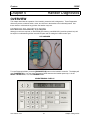
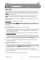
OVERVIEW
The test site on the Handler may be interfaced to virtually any programmer and/or tester available. Some
interfaces require custom configuration prior to shipment but the only requirement for a given programmer
or tester is that it be capable of issuing and accepting commands to and from the handler or the system
controller. There are two basic parts to the handler's interface with your programmer/tester.
1. The first part is the "DUT Interface." The DUT Interface connects the handler's test contacts to the
tester's test socket. There are many ways to accomplish this, depending upon application and type of
changeover kit. A direct dock interface which connects the tester directly to the handler contacts
provides the best performance, although other interface methods are available. In most cases, the
hardware required for the DUT Interface will be built and installed at EXATRON. Therefore, the DUT
Interface will not be discussed in this section of the user's guide.
2. The second basic part to every interface is the "Control Interface." The Control Interface allows
the handler to send a Start to the tester and subsequently allows the tester to instruct the handler how
to process the device under test. The handler is equipped with a variety of ways to accomplish this
task using two basic means of access: a parallel port (EXATRON’S “Handler Port”) and an RS-232
serial port.
RS-232 PORT
HANDLER
PORT
The handler has a number of operating features which relate to the handler's tester control interface. Both
the Handler Port and RS-232 Port have several distinctive options from which to choose. These various
control interfaces available from EXATRON are the subject of the following discussion. They have been
organized into three categories:
A. General Interface Options, (common to both Handler Port and RS 232 Port)
B. Handler Port Interface Options.
C. RS-232 Interface Options.
Please read through all of the firmware options in this chapter to determine exactly which interface will
meet your specific application requirements.
www.exatron.com
3-1
Chapter 3 Interface Info
Exatron
3000B
General Interface Options and Set Up
Accessing a Handler Control Interface:
When the handler powers up, you will be given the opportunity to, PICK INTERFACE? If you press the
[Enter] button, the previously selected interface (or default interface, if RAM was cleared) will be selected.
Listed below are the standard interfaces currently supplied with the handler. NOTE: New interfaces are
added to the handler from time to time. Please contact EXATRON for updates as required. Our toll-free
telephone number is: 1-800-EXA-TRON.
From “PICK INTERFACE?” displayed on the front panel:
[1] Key
Sets the handler to use "HANDLER PORT"
[2] Key
Sets the handler to use “EXATRON SUPER”
[3] Key
Sets the handler to use “H P RS-232”
[NOTE: FOR “LABEL/TEST,” “LABEL ONLY,” AND “TEST ONLY” OPTIONS, PLEASE REFER
TO THE MODEL 3000B-L USER’S MANUAL.]
[4] Key
Sets the handler to use “PROGRAM RS-232”
[5] Key
Sets the handler to use “EXATRON RS-232”
[Enter] Key Sets your choice into the handler.
[Clear] Key Rejects selection and returns to PICK INTERFACE?.
General Interface RAM Selections:
Listed below are addresses in the handler’s battery backed-up RAM which may be edited to fine tune the
handler for your specific programmer/tester and sorting requirements when using either the Handler Port
(parallel) or the RS-232 serial port. These addresses are not part of the standard power-up selections
and may be modified only by “Changing The RAM,” as described in the Handler Set-Up Chapter of
this manual.
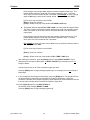
Interface Type:
Address 00D2
This address allows the user to set the default interface to be used by the handler. The following table
lists available settings:
data setting 21
data setting 23
data setting 24
data setting 25
data setting 26
data setting 27
data setting 28
Start Test Delay:
=
=
=
=
=
=
=
EXATRON SUPER
PROGRAM RS-232
LASER ONLY KIT [MODEL 5000 ONLY.]
EXATRON RS-232
HANDLER PORT
LOW GOING PULSE [USES SPECIAL PAL A89-2LP.]
H P RF RS-232
Address 0097
For DIP devices only, this delay adds "settling" time to the DUT. The delay allows the DUT more time to
come to rest in the test site before the contacts close. The delay counts down in HEX, in 1 millisecond
steps.
www.exatron.com
3-2
Chapter 3 Interface Info
Exatron
3000B
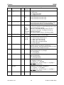
Pick Up Delay:
Address 00A9
This delay allows additional time after the handler has detected the device under the plunger before
turning on the vacuum to pick up the DUT at the start of the test cycle. The delay counts down in HEX, in
10 millisecond steps. This feature applies to Plunge-to-Board and Swing Head changeover kits only.
Stop On Fail Y/N:
Address
00AA
30 = Stop on Fail
FF = Run Failed Devices, No Stop
This option allows the handler to Stop on Fail, or not. The handler can either automatically cycle a failed
device into an output tube or the handler can be set to stop. If set to STOP ON FAIL YES, then the
handler will stop on a failure and allow the operator to retest the device again and again, as often as
desired. This is very useful when calibrating test fixtures and programs.
Gate Delay:
Address 00AB
This delay allows additional time for the test site gate to first open and then secondly, allows additional
time after the handler closes the gate at the end of the test cycle. The delay counts down in HEX, in 10
millisecond steps. This feature applies to Plunge-to-Board changeover kits only.
Double Test Sort:
Address 00BC
This address tells the handler which test sorts to double test if desired. A setting of “00” will turn off the
double test for all sorts. A setting of “FF” will set the tester to double test all devices. Assuming Sort 1 is
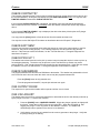
Pass and all other sorts are to be double tested, set this address to “FE.” Each bit represents a tester sort.
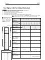
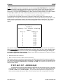
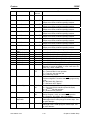
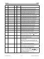
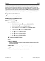
Tester Sort Set Up: Addresses 00C0 to 00C7
ASCII INPUT
1
2
3
4
5
6
7
8
✻
SORT
1
2
3
4
5
6
7
8
=
OUTPUT BINS
RAM ADDRESS C0
RAM ADDRESS C1
RAM ADDRESS C2
RAM ADDRESS C3
RAM ADDRESS C4
RAM ADDRESS C5
RAM ADDRESS C6
RAM ADDRESS C7
Remote Flush
0
=
Remote Retest
CURRENT SETTING
USED BY EXATRON RS-232
AND H P RS-232 ONLY
USED BY EXATRON RS-232
AND H P RS-232 ONLY
The handler uses the specifications shown in the table above to assign Output Bins to tester Sorts.
The “Current Setting” column is provided for the customer’s reference purposes. Please enter your
settings in this column.
If the handler does not receive one of the above test Sorts, the handler will pause and display the
message, “BAD TEST RESULT.” The handler will output the HEX equivalent of the actual character
received by the handler to the LEDs on the handler’s output shuttle cover. LED #1 is bit 01, LED #8 is bit
80. Pressing the [Clear] button on the handler’s front panel will flush the device from the test site and
restart operation. Press [Enter] to retest, if desired.
When the handler does receive a proper result in the form of one of the above test Sorts, the handler will
open the test contacts and flash the output cover LED of the output bin selected. The handler will sort the
DUT accordingly and start a new handling cycle.
www.exatron.com
3-3
Chapter 3 Interface Info
Exatron
3000B
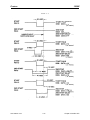
Handler Binning Setup
I.Introduction:
EXATRON handlers are designed to accept as many as eight sort messages from your tester/programmer
equipment. Selecting which output bins the handler will then put your devices in is accomplished by
programming the handler to match physical output bins to tester sort results. The tester sort signals will
come into the handler via the Parallel Port or the RS232 Port. Please refer to the Interface Information
chapter of this manual for further reference on tester-handler communication.
II. Designing Bin Assignments:
A.
Pass, Retest, Fail
Typically, there are three main categories of test results: devices that pass test, devices that definitely fail
test, and devices that may or may not have failed. This last category is best understood as continuity
errors, missed contacts, devices in test during power outages, etc. These are devices which may in fact
be good devices but which need to be retested.
If the test program in use is designed to differentiate between fail and retest devices, then EXATRON
recommends bin 5 as the retest bin. Assign bins 4 and/or 6 as the positive fail bins in this situation.
Where no differentiation is made between fail and retest devices, then assign bin 5 for these devices.
B.
Positive Binning
Positive binning is the concept of designing the bin assignments to minimize the ill effects of accidental
binning errors. All EXATRON handlers have very substantial mis-binning protection built in. It is impossible
to say absolutely that no mis-bins will ever occur. As a defense against accidental mis-binning, it is
generally considered bad practice to carry “fail” or “retest” devices to their bins over the tops of any good
device bin. It is better to accidentally drop a good device in a fail bin than to accidentally drop a failed
device in a good bin.
Output from
handler
Shuttle, moves over
Bins
1
2
3
4
5
6
7
8
Outside
Inside
Outside
Looking at the above diagram, it would be inappropriate to put anything but “retest” or “fail” devices in bin
5. If bin 5 is assigned as a good bin, then some other bin must be assigned as a fail bin. It would then be
necessary to carry a failed device across the good bin 5 to some other location. This is not recommended.
If your test results provide for grades, then the best grades should be in the outside bins, with lower
grades toward the inside. If a highest-rated device is accidentally dropped in a lower-grade bin, that is not
as bad a problem as if a lower grade device is dropped in a higher-grade bin.
C.
Unused Sort Signals
It is wise to always assign the “retest” tube as the output for unused sort signals. This acts as a defense
against “ghost” signals which may occur as a result of tester interface “noise” or power fluctuations.
III. Finding Bin Assignment Data:
To figure out the correct binning data for your desired tube outputs, please consult the “ Test Signal
- Bin Sort Data Worksheet” which accompanies this document.
www.exatron.com
3-4
Chapter 3 Interface Info
Exatron
3000B
IV. Storing Bin Assignments in Handler Memory:
The handler uses a look-up table to assign handler output bins/tubes to tester sort signals. The output
tube parameters are stored as a two digit hexadecimal number in the handler’s memory (e.g.: “E5”). The
first digit describes what happens with tubes numbered five through eight, and the second digit describes
what happens with tubes numbered one to four. The first digit is called the “Most Significant Bit” and the
second, the “Least Significant Bit.”
You will need to edit the memory addresses in the handler’s battery backed-up RAM to store your desired
binning data. A chart with all relevant memory addresses is shown at the end of this document and on the
Test Signal - Bin Sort Data Worksheet.
To edit the Handler memory from the front panel display, follow this procedure:
1.0 Make sure you have a copy of the EXATRON-supplied RAM address listing for your system. While
most handlers store the binning information as described in the chart on the worksheet, some custom
handlers have variations in addresses. A copy of this address listing is in the supplemental chapter at
the end of this manual.
2.0 Verify that the handler is in Manual Mode. Display will read MANUAL MODE.
3.0 Press the [SET UP] key. Display will read CHANGE RAM ? NO.
4.0 Press the [SET UP] key. Display will read CHANGE RAM ? YES.
5.0 Press the [Enter] key. Display will read LOAD DEFAULT ? NO.
6.0 Press the [Enter] key. Display will read 0090 DATA 01 The handler is now in the edit mode of the
handler’s battery backed-up RAM.
7.0 Press the [SET UP] key to increment the address. The [TOTALS] key will decrement the address.
8.0 Press the [SET UP] key until address 00C0 is displayed. Display will read 0C0 DATA xx, where xx
is the hexadecimal data at that address. Address 00C0 is the address where data for Sort Signal 1 is
stored on standard handlers. Note that LEDs on the output door are now flashing. The flashing lights
indicate which tubes are currently selected for Sort 1. If you change the data, the flashing lights will
change as well. Use this visual confirmation for the tubes you have selected.
9.0 If necessary, change the data at this address:
9.1
9.2
9.3
9.4
9.5
Press the [Space] key to increment the first data digit (the most significant data bit.)
Press the [Delete] key to increment the second data digit (the least significant data bit.)
Press the “ [0] ” key to set the data at that address to 00.
Press the “ [ – ] ” key to set the data at that address to FF.
Press the [Clear] key to load the EPROM default data at that address.
10.0
When finished editing this address, press the [SET UP] key until the next relevant address is
shown. Consult the handler memory address chart below.
11.0
Edit this address as described above in section 9.0.
12.0
Continue this process until all addresses have been changed to proper data. Note that if your
tester/programmer uses less than eight signal outputs, you should assign the fail bin to all
remaining sort signals.
13.0
When finished editing, press the [Enter] key to exit editing and set the new DATA into RAM.
www.exatron.com
3-5
Chapter 3 Interface Info
Exatron
3000B
Memory addresses in
handler
memory for output binning
data:
Sort #
Address
1
00C0
2
00C1
3
00C2
4
00C3
5
00C4
6
00C5
7
00C6
8
00C7
www.exatron.com
3-6
Chapter 3 Interface Info
Exatron
3000B
Test Signal - Bin Sort Data Worksheet
Instructions:
1. Write the number of the sort signal you are working on under “Sort Signal #”.
2. Write a “1” under each tube you wish to use for that signal.
3. Write a “0” under each tube you are not using.
4. Compare the pattern with the chart on the left of the page.
5. Enter the Data result under each pattern.
6. Put that data result in the handler memory at the address shown for that sort number.
Note: Tube #s are written in DESCENDING order below; they appear
in ascending order on the face of the handler output door.
This example shows how to
derive binning data. Using
bins 1, 3, 7 & 8, the binning
data is C5. Consult handler
chart (bottom) for proper
address.
Sort
Signal
Patterns
8
7
6
5
4
3
2
1 __
1 __
0 __
0 __
0 __
1 __
0
__
C
O
M
P
A
R
E
Compare the
pattern from
the
worksheet
with this
chart to
determine
hex data:
Pattern
Data
0000 0
0001 1
0010 2
0011 3
0100 4
0101 5
0110 6
0111 7
1000 8
1001 9
1010 A
1011 B
1100 C
1101 D
1110 E
Hex Data
Numeral
W
R
I
T
E
I
N
Memory addresses in
handler memory for sort
binning data:
Sort # Addr.
1
00C0
2
00C1
3
00C2
4
00C3
5 www.exatron.com
00C4
6
00C5
7
00C6
8
00C7
Sort
Signal
Patterns
C
____
8
7
6
1
1
5
____
5
4
3
2
1
__ __ __ __ __ __ __
Hex Data
Numeral
Sort
Signal
Patterns
8 7
Hex Data
Numeral
Sort
Signal
Patterns
____
8
7
6
____
5
4
3
2
1
__ __ __ __ __ __ __
6 5 4 3 2 1
____
8
7
6
____
5
4
3
2
1
__3-7 __ __ __ __Chapter
__3 Interface
__ Info
Exatron
Sort
Signal
Patterns
3000B
8
7
6
5
4
3
2
1
__ __ __ __ __ __ __
Hex Data
Numeral
Sort
Signal
Patterns
____
8
7
6
____
5
4
3
2
1
__ __ __ __ __ __ __
Hex Data
Numeral
Sort
Signal
Patterns
____
8
7
6
____
5
4
3
2
1
__ __ __ __ __ __ __
Hex Data
Numeral
Sort
Signal
Patterns
____
8
7
6
____
5
4
3
2
1
__ __ __ __ __ __ __
Hex Data
Numeral
Sort
Signal
Patterns
____
8
7
6
____
5
4
3
2
1
__ __ __ __ __ __ __
www.exatron.com
3-8
Chapter 3 Interface Info
Exatron
3000B
Handler Port Interface
THE HANDLER PORT INTERFACE USES SIMPLE TTL-COMPATIBLE SIGNALS TO CONTROL THE HANDLER. This
parallel port interface utilizes the 24 pin “D” connector on the side of the handler. It has been designed
to be compatible with “MCT-type” tester control interfaces.
The HANDLER PORT interface uses the addresses 00C0 through 00C7 for tester sort to output bin and
address 00BC for double test on/off selection. Please refer to the General Interface RAM Selections
section at the beginning of this chapter for further details.
Handler Port Pin Out:
Sort Input 1
Pin 1
Pin 13
Sort Input 2
Pin 2
Pin 3
Pin 4
Pin 5
Pin 6
Pin 7
Pin 8
Pin 9
Pin 10
Pin 14
Pin 15
Pin 16
Pin 17
Pin 18
Pin 19
Pin 20
Pin 22
Pin 22
Pin 11
Pin 12
Pin 23
Pin 24
Sort Input 3
Sort Input 4
Sort Input 5
Sort Input 6
Sort Input 7
Sort Input 8
2
nd
Start
Output 1, Start
Test: Pulse
Handler Vcc, +5 VDC
Handler Ground
Input 9, End of
Test
Not Used
Not Used
Not Used
Output 8
Output 7
Output 6
Output 5
Output 4
Output 2, Start
Test: Level
Handler Vcc, +5 VDC
Handler Ground
SPECIAL PAL REQUIRED
FIGURE 3-1A
HANDLER INTERFACE PORTS DETAIL
OPTIONAL OPTO ISOLATION PORT
SEE 5000-D76 FOR DETAILS
MATING CONNECTOR T&B #609-2030
Sort 1 1
Sort 2 2
Sort 3 3
Sort 4 4
Sort 5 5
Sort 6 6
Sort 7 7
EOT 8
nd
2 Start 9
Start Test Pulse 10
Handler Vcc +5VDC 11
Tester Ground 12
www.exatron.com
13
14
15
16
17
18
19
20
21
22
23
24
Not Used
Not Used
Not Used
Not Used
Output 8
Output 7
Output 6
Output 5
Output 4
Start Test Level
Handler Vcc+5VDC
Tester Ground
3-9
NOTE: NEVER CONNECT
OPTO GROUND TO
HANDLER GROUND OR
OPTO Vcc TO HANDLER
Vcc
Chapter 3 Interface Info
Exatron
3000B
FIGURE 3-1B
HANDLER INTERFACE PORTS DETAIL
HANDLER PORT SEE 5000-A89 FOR DETAILS
MATING CONNECTOR CINCH #57-30240
Sort 1 1
Sort 2 2
Sort 3 3
Sort 4 4
Sort 5 5
Sort 6 6
Sort 7 7
Sort 8 8
nd
2 Start 9
Start Test Pulse 10
HandlerVcc +5VDC 11
Handler Ground 12
13
14
15
16
17
18
19
20
21
22
23
24
Input 9 EOT
NOTE: NEVER CONNECT
Not Used
TESTER Vcc TO
Not Used
HANDLER Vcc
Not Used
Output 8
Output 7
Output 6
Output 5
Output 4
Start Test Level
HandlerVcc +5VDC
Handler Ground
REMEMBER:
1. Use the 24-pin handler port.
2. All signals are TTL/CMOS compatible.
3. Opto-isolation is available as an optional feature except on the 2000B
Series Handlers. To obtain this feature for your Model 3000B or Model
5000 Handler, please specify your request at the time of placing your
handler order.
Additionally, all 3000B and 5000 Series Handlers may be upgraded to
opto-isolation in the field. To order this upgrade for an existing handler,
contact the EXATRON Sales Department and order PCB #5000-D76,
"Opto Isolation Interface/Light Pole Option PCB." Our toll-free telephone
number is 1-800-EXA-TRON.
4. The +5 volt output on the handler port (Pins 11, 23) is NOT to be used by or connected to
the tester, unless it is isolated at the tester.
5. Pins 12 and 24 are ground connections.
6. Refer to FIGURE 3-2 following, for timing diagram.
For further timing/sort details, please refer to DRAWING #5000-F62.
www.exatron.com
3-10
Chapter 3 Interface Info
Exatron
3000B
FIGURE 3-2
HANDLER PORT INTERFACE Timing Detail
The handler first moves a device into the test site. After allowing time for the device to settle, (NOTE:
this settling time is programmable; use address 0097) the test head plunger picks up the device and
plunges it down toward the contactors. Then the handler issues a start pulse (Pin 10) to the tester.
The start pulse width is programmable, (address 0098) but will be pre-set to 20 milliseconds. This
pulse is normally High (+5) and goes Low for the pulse width. There is an additional signal available on
Pin 22. This testing signal will go Low for the duration of the test. It will go Low at the start of the start
pulse and will not go High again until the handler receives a sort signal.
SORT MUST BE STABLE FOR 1 MSEC MINIMUM PRIOR TO EOT
PULSE OR LEVEL
HANDLER ALLOWS ONLY
ONE SORT INPUT PER TEST
ALL HANDLER INPUTS AND
OUTPUTS STANDARD
TTL LOGIC
NORMALLY HIGH
ACTIVE LOW
20 MSEC
ADJUSTABLE
TEST TIME
INDEX / SORT TIME
To complete the test, the tester must send back one of eight sort signals. These signals must be normally
High and go Low for at least two milliseconds. The sorts must appear on Pin 1 through Pin 8 on the
handler port connector. We recommend that you use Pin 1 for PASS and Pin 2 for FAIL when using the
handler in PASS/FAIL applications.
The Input Sort is connected to a PAL device which "latches" the signal. The latch sets the falling edge of
the sort signal ON. Make certain that your interface does not allow fast "glitches" which may become
latched, causing the handler to mis-sort. If desired, the PAL may be modified to one that requires an "End
of Test" edge as well. Further details are provided in the Handler Port Options section later in this
chapter.
www.exatron.com
3-11
Chapter 3 Interface Info
Exatron
3000B
To abort the test, press the [Clear] button on the handler controller. This will sort the DUT to the Home
bin, output tube 5.
Once the handler receives a sort pulse, it checks that:
1. The sort has a corresponding output. If not, you will see:
NO SORT ERROR displayed, advising that there are no outputs available.
2. Only one sort has been received. Only one sort signal is allowed. If multiple sorts were
received, you will see: MULTI SORT ERR displayed. The output shuttle cover LEDs will blink
the pattern of the actual sorts latched by the handler. Two or more LEDs will blink, indicating
the multiple sort error.
If the received sort pulse is acceptable, the contacts will open and the device will be sorted to an output
tube. Or, in the case of plunge-to-board changeover kits, the test site plunger will pick up the device and
rise to its highest point. From there, the device will be sorted to an output tube.
Handler Port Options:
EOT (END OF TEST)
The handler port is controlled by two PAL devices. These PALs control the polarity of the
handler's input/output signals and whether "EOT" is to be used or not. The EOT input (pin 13) is not
active unless the correct PAL is installed on the handler’s Front Panel Card #5000-A89. The EOT
signal, when used, will cause the handler to ignore all tester sort input signals until the EOT (normally
High, active Low) is received by the handler.
PAL 101-12.JED (Sum check 76B0) = No EOT signal required.
PAL 101-12EOT.JED (Sum check 75B0) = EOT signal required by the handler.
CORRECT PALS MAY ALWAYS BE OBTAINED FROM EXATRON AT NO CHARGE.
Listed below are addresses in the handler's battery backed-up RAM which may be edited to fine-tune
the handler for your specific programmer/tester and sorting requirements. These addresses are not
part of the standard power-up selections and may be modified only by “Changing The RAM,” as
described in the Handler Set-Up Chapter of this manual.
START PULSE WIDTH: ADDRESS 0098
This delay controls the Start of Test pulse width. The delay counts down in HEX, in 1 millisecond
steps. The standard default is "14." This sets the start test pulse width to 20 milliseconds. On
interfaces using a PC to control the handler, a longer start pulse width may be required to guarantee
that the PC sees the start test pulse from the handler.
CHECK SORT RESET: ADDRESS 00A6
00 = On
FF = Off
The Check Sort Reset feature should always be used on handlers which are employing the
Handler Port interface. This check verifies that all Sort signals to the handler are turned off at the end
of the Start pulse (all Sorts are at Logic High.)
Occasions may arise during operation of the Handler Port interface when the handler sends a Start
pulse to the tester but the tester either does not see the Start signal, or the tester fails to clear the
previous Sort signal. In the latter case, the previous Tester Sort signal is still active at the end of the
Handler's current Start pulse. The handler correctly responds to the previous Sort signal, which means
that the current device under test (DUT) will not be tested and will be mis-sorted. It may appear to the
www.exatron.com
3-12
Chapter 3 Interface Info
Exatron
3000B
operator that the handler is making an error, when in fact the tester has made an error. Therefore, it is
a good idea to set this check to On whenever your application allows for it.
SECOND START PULSE FEATURE
2ND START WIDTH: ADDRESS 00D8
2ND START DELAY: ADDRESS 00D9
ND
Exatron has added a “2 START PULSE” to the EXATRON Handler Port interface. This second
start pulse is to be used in the event that the tester you wish to use has a problem with the handler’s
ND
standard start pulse timing. Use this “2 START PULSE” only to solve interface problems flagged by
the error messages: SORT NOT RESET and/or MULTI SORT ERROR.
♦
For correct use of the handler’s standard start pulse, the tester must reset all sort signals to Logic
High on the leading/falling edge of the standard start pulse. The handler resets its input sort latch on
the rising edge of the start pulse. At that instant in time, if any sort signals are still present from the
tester, they will be latched into the handler’s sort latch. This could cause the handler to sort an
untested device to an output bin based on the previous tester bin result. In many cases, the
mechanical motion of the handler will allow both the previous bin result plus the new bin result to be
latched into the handler’s sort latch. This will result in a MULTI SORT ERROR message. The
handler’s output cover LEDs will flash the input error combination. Typically, a Pass and a Fail input
will flash at the same time.
♦
It may be that your tester does not respond to either edge of the handler’s start pulse. This is a
common problem with PC-based testers. In this case, making the standard start pulse longer may
correct the problem.
♦
It may be that your tester resets the sorts on the rising edge of the handler’s standard start pulse. In
this case, making the standard start pulse longer will have no effect. You now have the option to use
ND
the “2 START PULSE.” You may, from the handler’s front panel, adjust the second start pulse to
start before the standard start pulse, and/or end after the standard start pulse. You may now use the
rising edge of the second start to reset the tester, independent of the rising edge of the standard start.
Care must be taken to be absolutely sure that the tester’s sorts are completely reset before the end of
the start pulse used by the tester.
ND
Please refer to FIGURE 3-3 on the following page for timing diagrams of several “2 START” set up
examples. If you are having interface problems, please call the EXATRON factory for free customer
service advice. Our toll-free telephone number is: 1-800-EXA-TRON. EXATRON cannot be held
responsible for mis-sorted devices when the tester’s sort signal timing is not correctly set up and fully
understood by the customer.
www.exatron.com
3-13
Chapter 3 Interface Info
Exatron
3000B
FIGURE 3-3
www.exatron.com
3-14
Chapter 3 Interface Info
Exatron
3000B
RS-232 Interfaces
EXATRON SUPER ~ EXATRON RS-232 ~ H P RS-232 ~ PROGRAMMER RS-232
RS-232 Port Options:
Listed below are addresses in the handler's battery backed-up RAM which may be edited to fine tune
the handler for your specific programmer/tester and sorting requirements. These addresses are not
part of the standard power-up selections and may be modified only by “Changing The RAM,” as
described in the Handler Set-Up Chapter of this manual.
BAUD RATE
009A
__
009A
009A
009A
009A
009A
009A
009A
06
0C
18
30
60
C0
80
This address stores the baud rate setting for the RS-232 serial port. The RS-232
port uses the 25 pin RS-232 connector on the side of the handler.
19200 Baud
9600 Baud [Default setting]
4800 Baud
2400 Baud
1200 Baud
600 Baud
300 Baud
DATA FORMAT
009B
009B
009B
009B
009B
009B
009B
009B
009B
009B
009B
009B
009B
009B
009B
009B
009B
009B
009B
009B
009B
__
02
2A
3A
1A
0A
06
2E
3E
1E
0E
03
2B
3B
1B
0B
07
2F
3F
1F
0F
www.exatron.com
This address stores the data format setting for the RS-232 port.
No parity
7 Data 1 Stop
Stick one
7 Data 1 Stop
Stick zero
7 Data 1 Stop
Even parity
7 Data 1 Stop
Odd parity
7 Data 1 Stop
No parity
7 Data 2 Stop
Stick one
7 Data 2 Stop
Stick zero
7 Data 2 Stop
Even parity
7 Data 2 Stop
Odd parity
7 Data 2 Stop
No parity
8 Data 1 Stop [Default setting]
Stick one
8 Data 1 Stop
Stick zero
8 Data 1 Stop
Even parity
8 Data 1 Stop
Odd parity
8 Data 1 Stop
No parity
8 Data 2 Stop
Stick one
8 Data 2 Stop
Stick zero
8 Data 2 Stop
Even parity
8 Data 2 Stop
Odd parity
8 Data 2 Stop
3-15
Chapter 3 Interface Info
Exatron
3000B
Exatron Super
The Exatron Super interface allows for computer control of the handler, tester/programmer, and
label/laser marker as a complete system. This interface uses the handler’s RS-232 Control Port to
communicate with the controlling computer running Exatron E5000 laser software or Exatron Label Maker
software. The actual connection to the computer is usually COM1, COM3, or the first port on the
Digiboard I/O box. This may vary depending upon your handler's configuration.
All aspects of production are controlled by the computer carrying out instructions as they are defined in a
file called a "Job." Job files may be created, edited and saved as desired by the operator.
All serial connections are 25 pin to 25 pin “straight through.” If a special cable is needed for your
programmer/tester, please provide Exatron with the pin out configuration or the cable itself, so that we
may furnish compatible interface hardware.
The communications settings are fixed in the firmware at 9600 Baud, No Parity, 8 Data Bits, 1 Stop. All
serial devices connected to the Exatron controlling computer should be so configured.
The connector on the handler is a 25 pin RS-232-type “D” connector with female pins. The mating
connector on the interface cable must use male pins. The RS-232 side panel port uses the following pins:
Pin 1 = GROUND
Pin 2 = RECEIVE; input to handler
Pin 3 = SEND; output from handler
Pin 7 = GROUND
Typically this cable is wired one to one (1 : 1) to the RS-232 port on the back of a PC using a 25 pin RS232 connector. If your PC uses a 9 pin RS-232 port, then, typically use a straight through interface cable.
Laser Only Kit:
[model 5000 only.]
This special interface is a sub-set of the Exatron super interface. It is intended to be used with change
over kits which do not have a test site, i.e. kits which are for laser marking only. Please refer to the
EXATRON SUPER section above for additional information on how to use this interface. As with the EXATRON
SUPER interface, the communications settings are fixed in the firmware at 9600 baud, no parity, 8 data
bits, 1 stop.
The following address in the handler's battery backed-up RAM may be edited to fine tune the handler for
your specific programmer/tester and sorting requirements. This address is not part of the standard powerup selections and may be modified only by “Changing The RAM,” as described in the Handler Set-Up
Chapter of this manual.
REMOTE GO: ADDRESS 0099
00 = On
FF = Off
This address must be set to On for the controlling computer to have access to the handler's RAM. If this
address is not set properly, the handler will display the message: WAITING FOR PC.
www.exatron.com
3-16
Chapter 3 Interface Info
Exatron
3000B
EXATRON SUPER RS-232 CONTROL COMMANDS: [5000 SERIES ONLY.]
This information is subject to change without notice. Contact EXATRON for latest revision. The following
RS-232 control commands are used by the EXATRON 5000 Series Handlers. The handler must be set to
use the EXATRON Super interface only. These commands do not apply to the handler’s Programmer
RS-232 interface, or EXATRON RS-232 interface, or to any other RS-232 interface.
For firmware: “5000FAST”
TEST [CR]
The handler has loaded a device into the test site. (The top test site in dual site
handlers.) The tester should now start testing the DUT for the first time. No answer is
required. Do not send the End Of Test (EOT) sort until the handler specifically asks for
END TEST [CR].
END TEST [CR]
Requests the End Of Test (EOT) sort for the DUT in the test site.
The handler must receive an answer before continuing operation. Send back a single
ASCII character. The only legal answers are the numbers 1 through 8.
Example: for Sort 1, PASS, send a “1”
for Sort 2, FAIL, send a “2”
RETEST [CR]
The handler has unloaded a device from the contacts and has reinserted it for a double
test operation. (The top test site in dual site handlers.) The tester should now begin
testing the same DUT for the second (or multiple) time. No answer is required. Do not
send the EOT sort until the handler specifically asks for END RETEST [CR].
END RETEST [CR]
Requests the End Of Test (EOT) sort for the DUT(s) in the test site. The handler must
receive an answer before continuing operation. Send back a single ASCII character. The
only legal answers are the numbers 1 through 8.
Example: for Sort 1, PASS, send a “1”
for Sort 2, FAIL, send a “2”
MARK [CR]
For lasers equipped with optional quad mark firmware only. This command will be sent to
the PC by the handler immediately after EOT. The DUT to be marked will typically be
moving into the laser mark site. This command will serve as a “preload” mark command.
Once the PC receives this command, the correct “MARK” will be loaded into the laser
marker and displayed with yellow background on the PC screen. There is no response
required from the PC.
FIRE LASER [CR]
The handler has loaded a DUT into the mark site. The laser should begin laser marking
the DUT. No answer is required. Do not send the End-Of-Mark until the handler
specifically asks for END LASER [CR].
www.exatron.com
3-17
Chapter 3 Interface Info
Exatron
3000B
END LASER [CR]
The handler is requesting an End-Of-Mark answer. Send an ASCII “Z[CR]” when the laser
mark is complete.
ERROR [CR]
The handler has received a command, but the command was not understood or is not one of
the legal commands used by the handler. No answer is required, but if you want the handler
to perform some operation, then retry your previous command.
COMMANDS FROM THE PC TO THE HANDLER:
1 [CR] = SORT 1
2 [CR] = SORT 2
3 [CR] = SORT 3
4 [CR] = SORT 4
5 [CR] = SORT 5
6 [CR] = SORT 6
7 [CR] = SORT 7
8 [CR] = SORT 8
+ (plus) = Put handler in Listen mode.
+ A90 [CR] = Ask handler to send a specific EPROM/RAM address setting:
“?? ROM ?? RAM ??”
+ B [CR] = Reset all handler tube/total counters to zero.
Handler display will read, TOTALS SET TO 0.
+ C90 FF [CR] = Accept new RAM settings from PC.
+ = plus
C = “C” command
90 = address
= space
FF = new data for address location
[CR] = end of string
+ D [CR] = Loads handler EPROM default settings into the handler’s RAM address,
from 0090-00FF to E390-E3FF.
Handler display will read: LOAD EPROM > RAM.
+ E [CR] = Send EPROM/RAM address “labels”
+ F [CR] = Send RAM data from handler to PC. Handler returns a long string of 8 bit
characters, one character for each address location from E390 to E3FF, ending
with a [CR].
+ G [CR] = Go; Index a new DUT, start running operations.
+ I [CR] = Handler returns EPROM default settings addresses 0090 - 00FF.
+ P [CR] = Pause the handler. Press the handler RUN button to restart operation.
+ T [CR] = Send RAM data from PC to handler RAM E390 - E3FF.
+ Z [CR] = Laser mark finished.
www.exatron.com
3-18
Chapter 3 Interface Info
Exatron
3000B
REMOTE RAM COMMANDS:
“A” command = Request ROM/RAM address setting.
To check a single address setting in both the
handler’s ROM and RAM, send “A90 [CR]”.
A for address, 90 to FF for a given address.
The handler will send back:
90 ROM 01 RAM 01 [CR]
This displays the current address location
selected, the ROM default setting, and the
current RAM setting.
“P” command = Pause Handler
First, send a + (plus) to the handler; wait for the
handler to return a + (plus.) The handler is now
ready to receive a command.
Send “P [CR]” to the handler. The handler will
complete its current sub-cycle and will PAUSE the handler as soon as
possible. The display will read: HANDLER PAUSED.
To restart the handler, press the RUN button on
the handler’s control panel.
Exatron RS-232:
The Exatron RS-232 interface allows the handler to be interfaced to virtually any computer-based piece of
test equipment. The user must write a program which communicates with the handler using the
commands listed in this section. This interface is unlike EXATRON'S other control interfaces.
The connector on the handler is a 25 pin RS-232-type “D” connector with female pins. The mating
connector on the interface cable must use male pins. The RS-232 side panel port uses the following pins:
Pin 1 = GROUND
Pin 2 = RECEIVE; input to handler
Pin 3 = SEND; output from handler
Pin 7 = GROUND
The baud rate, stop bits, data bits, and parity may be selected by setting an address (RAM address 009B
= baud rate, 009C = data format) in the handler's EPROM. Please refer to the General Interface Firmware
Address section at the beginning of this chapter for Baud Rate and Data Format settings. The standard
EXATRON RS-232 settings are: 9600 Baud, No Parity, 8 Data Bits, 1 Stop.
www.exatron.com
3-19
Chapter 3 Interface Info
Exatron
3000B
BASIC HANDLER/CPU TEST CYCLE HANDSHAKE
Summary:
[EXATRON uses only standard upper case ASCII characters.]
1.
2.
3.
4.
5.
6.
7.
HANDLER SENDS AN "H [CR]."
TESTER SENDS AN "R," READY.
HANDLER CLOSES TEST CONTACTS ONTO THE DEVICE UNDER TEST (“DUT.”)
HANDLER SENDS AN "S [CR]," START TEST (FIRST TEST CYCLE.)
TESTER SENDS TEST SORT RESULT, “1” THROUGH “8” OR "0" FOR REMOTE RETEST.
HANDLER OPENS TEST CONTACTS.
DUT CYCLES TO AN OUTPUT TUBE; A NEW CYCLE STARTS.
SPECIAL NOTE: REMOTE FLUSH ~ The tester can send an asterisk, “✻,” (“2A” in HEX) as a handler
reset command. If the handler receives an asterisk, the test will be aborted and the device will be flushed
to the Home bin, output tube 5.
SPECIAL NOTE: REMOTE RETEST ~ You may send a zero, “0,” to the handler as a test result. This
will cause the handler to pick up the device and replunge/retest it. A new "S" will be sent to the tester.
You may use the "0" response as many times as you wish. To end a test cycle, send the handler a "1"
through "8" as a sort command.
BASIC HANDLER/CPU TEST CYCLE HANDSHAKE
With Explanation:
1. HANDLER SENDS AN "H [CR]."
The handler establishes proper communications at the outset of every cycle (except Retest cycles.) To do
so, an "H" and a carriage return, “[CR],” are sent by the handler to the tester at the start of each test
cycle. The handler is seeking an "R," Ready, from the tester. The display will read: WAITING FOR R.
2. TESTER SENDS AN "R," READY.
3. HANDLER CLOSES TEST CONTACTS ONTO THE DEVICE UNDER TEST (“DUT.”)
If an “R” is received, the handler will close the contacts or plunge the device onto the contacts. If the
handler does not receive a response, the display will briefly read: NO RESPONSE. NO RESPONSE will
alternate with: WAITING FOR R once per second. Pressing the [Enter] button on the front panel will
cause the handler to send a new "H."
✻” is received, the handler will pause and display the message: BAD
If anything other than an “R” or an “✻
RESPONSE. The handler will output the HEX equivalent of the actual character received by the handler
to the LEDs on the handler’s output shuttle cover. LED #1 is bit 01, LED #8 is bit 80. Pressing the [Enter]
button on the front panel will cause the handler to send a new "H" and the handler will try again to receive
an "R." Pressing the [Clear] button on the front panel will cause the handler to flush the device from the
test site and restart operation. The display will read: BIN 5 S0 FLUSH.
4. HANDLER SENDS AN "S [CR]," START TEST (FIRST TEST CYCLE.)
As stated above, once the handler receives an “R,” the test contacts will close onto the DUT. The
handler will allow time for the test contacts to close. Then the handler sends an “S [CR]” for Start Test, to
the tester. The display will read: START 1 TEST.
If you wish to abort the test at this point, press the [Clear] button. This will sort the DUT to the Home bin,
output tube 5.
www.exatron.com
3-20
Chapter 3 Interface Info
Exatron
3000B
NOTE: If the handler receives an incorrect bin sort, the message: BAD TEST RESULT will be displayed.
The handler display will also flash the HEX equivalent of the result received on the handler's output door
LED’s. You may press the [Enter] button to reissue a Start Test command and the handler will try a
second test. You may press the [Clear] button to abort the test and restart operation, or send the handler
✻" or "2A" in HEX. This will automatically flush the DUT and begin a new test cycle.
an ASCII "✻
5. TESTER SENDS TEST SORT RESULT, “1” THROUGH “8” OR "0" FOR REMOTE RETEST.
To complete a test, the handler must receive a test result. Please refer to the TESTER SORT SET UP:
ADDRESSES C0 TO C7 table of correct test Sorts and the bins to which the handler will sort the DUTs. The
handler uses the specifications shown in this table to assign Output Bins to tester Sorts. The “Current
Setting” column is provided for the customer’s reference purposes. Please enter your settings in this
column.
Memory addresses in
handler
memory for output binning
data:
Sort #
Address
1
00C0
2
00C1
3
00C2
4
00C3
5
00C4
6
00C5
7
00C6
8
00C7
The customer may re-assign any combination of bins to any Sort by setting the selection in the handler’s
RAM. Be very careful not to assign the same bin(s) to a “PASS” and “FAIL” Sort. Once a Sort/Bin setting
has been determined and saved in the handler’s RAM, we highly recommend saving the settings in
the handler’s EPROM as default settings. Please contact the EXATRON factory for instruction on how to
save RAM changes in the handler’s EPROM.
6. HANDLER OPENS TEST CONTACTS.
7. DUT CYCLES TO AN OUTPUT TUBE; A NEW CYCLE STARTS.
The following address in the handler's battery backed-up RAM may be edited to fine tune the handler for
your specific programmer/tester and sorting requirements. This address is not part of the standard powerup selections and may be modified only by “Changing The RAM,” as described in the Handler Set-Up
Chapter of this manual.
D TEST ASCII OUT: ADDRESS 00AD
This address stores the ASCII letter which the EXATRON RS-232 interface will use as an output
on a double test. The factory setting is an "S" (53 in HEX.) The user may wish to distinguish between
a "START 1 TEST" and a "START 2 TEST." The user may set this address to "D" (44 in HEX,) in
which case the handler will issue an "S" on a First Test Cycle and a "D" on any Double Test Cycles.
www.exatron.com
3-21
Chapter 3 Interface Info
Exatron
3000B
HP RS-232:
The HP RS-232 interface was originally added to the Model 5000 handler at the request of one of
Exatron’s customers at Hewlett Packard. The customer wanted to use the basic Exatron RS-232
Interface with some additional information sent from the handler to the computer controlling the
customer’s tester. This information adds to the basic Exatron RS-232 commands which we have
incorporated into our Series 5000 and Series 3000B handlers.
The way in which the handler starts and ends each test cycle for the H P RS-232 Interface is the same as
for the Exatron RS-232 Interface, described in the basic handler/CPU test cycle handshake above. The
following explains in detail the additional H P RS-232 commands:
1. Handler sends a "$G [cr]” Handler is running; light pole if present, is set to GREEN.
2. Handler sends a "$R [space] (16 ASCII character string [cr]" The light pole, if present, has turned
RED: Handler error message.
3. Handler sends a “$Y [space] (16 ASCII character string) [cr]” The light pole, if present, has turned
YELLOW: Handler error message
4. Handler sends a "$B [space] (16 ASCII character string) [cr]" The light pole, if present, has turned
BLUE: Bin information will be displayed.
5. Handler sends a “$L [space] PART DROPPED ? [cr]” The light pole, if present, has turned RED:
Operator to check for handler mis-cycle.
6. Handler sends a “$E [space] EMPTY/LOAD PART [cr]” The light pole, if present, has turned
YELLOW: Handler is empty; the operator should load devices into the handler and press the Enter
button.
The handler will send out message strings at various times during the handling cycle and upon all
error/jam conditions. All of these strings will start with a “$” (dollar sign) and end with a “[cr]” (carriage
return.) The handler does not require any input back from the tester’s computer. The handler sends
these messages to the computer as FYI information only.
After the “$” (dollar sign) there will be an upper case ASCII letter. This letter may indicate the status of the
handler’s light pole. (The light pole is optional equipment, obtained by special order.) Other letters are
used for specific error conditions. Except in the case of a “G,” the handler will then follow the ASCII letter
with a “[space]” and then with an up to 16 character upper case ASCII error message string. The final
character in the communication from the handler will always be a “[cr]” (carriage return.)
Message String Details:
G for GREEN - handler is running normally. No operator action is required.
R for RED - the handler is stopped with a serious jam condition and requires operator assistance. If your
handler is sending excessive RED error messages, check that the handler is properly set up and is in
good working order.
Y for YELLOW - the handler is stopped but not jammed. The operator should check the handler and
restart its operation. Yellow errors include the handler being in PAUSE, MANUAL, SETUP,
DIAGNOSTIC, and ALL MOTORS OFF modes.
B for BLUE - the handler is stopped and reporting the following bin information: bin number, sort, current
tube count.
www.exatron.com
3-22
Chapter 3 Interface Info
Exatron
3000B
L for a special case error. In the case of PART DROPPED ? message, the handler has failed to pick up
the device with the test site plunger. The operator may press the handler’s [Enter] button to have the
handler try again to pick up the device at the plunger. Or, the operator may press the [Clear] button to
abort the test cycle and flush any device at the test site plunger to an output tube.
E for the special case error that the handler is empty. EMPTY/LOAD PART message instructs the
operator to load new devices into the handler.
Programmer RS-232:
This interface uses the handler’s RS-232 Port. The control characters have been selected to drive various
types of prom programmers equipped with CRCs (Computer Remote Control.) The exact controls used
herein are not to be changed by the user. If you try to use this interface and encounter problems, please
contact Exatron for assistance. Please refer to “RS-232 Port Options” at the beginning of this section for
Baud Rate and Data Format settings.
The Programmer RS-232 interface is compatible with the following programmers:
BP Microsystems Models 1200 and 1400 with Advanced Feature Software
Also use: Exatron RS-232 Interface
Handler Port Interface
Data I/O Autosite E
Model 2900
Model 3900
Unisite
Exatron Peregrine
System General TurPro I
TurPro FX
The following addresses in the handler's battery backed-up RAM may be edited to fine tune the handler
for your specific programmer/tester and sorting requirements. This address is not part of the standard
power-up selections and may be modified only by “Changing The RAM,” as described in the Handler
Set-Up Chapter of this manual.
BIT CHECK: ADDRESS 00D1
00 = Bit check On
FF = NO bit check, Off
This address is used by the PROGRAMMER RS-232 interface only. The user may set the handler to
perform an “Illegal Bit” test at the start of the programming cycle, or not. EXATRON recommends leaving
this option turned On whenever possible.
P/V/L: ADDRESS 00D3
This address is used by the PROGRAMMER RS-232 interface only. The user may select the default
program/verify or load master operation in the handler.
The possible defaults are:
data = 02 = Program
data = 04 = Verify
data = 08 = Load master
www.exatron.com
3-23
Chapter 3 Interface Info
Exatron
3000B
Programmer RS-232 Troubleshooting Guide
Follow all troubleshooting steps in sequence.
1. When I click the RunALL icon at the start of a new job, the monitor
displays: “FE ERROR” message.
This error occurs when using a DATA I/O programmer only. The error message has been sent by the
DATA I/O programmer and is being displayed on your EXATRON equipment. This message is described in
the DATA I/O user manual as, “Undefined Error --- An error occurred that the CRC program could not
categorize. Document the method in which the error occurred and call DATA I/O to report the
problem.”
You may be able to correct the error without calling the programmer company using the following
information:
• The operator has likely used DATA I/O firmware to improperly select the package type -- PLCC, SOIC,
DIP, etc.
1. The file data sent to the programmer has test vectors that were written for a different package
type. This causes a problem, for example, when loading a file compiled for DIPs but the
parts to be programmed are PLCCs.
2. Refer to the DATA I/O user’s manual for instructions. This subject is covered in the
“Communications Parameters” section of the “Commands” chapter. Follow the instructions
entitled, “JEDEC I/O Translate DIP/LCC Vectors (Y,N)” to eliminate this programmer
problem.
• The operator has possibly selected a device type not supported by the Data I/O socket adapter.
1. Use the correct Data I/O socket adapter with the correct Data I/O firmware and the correct
translation format code for the Data I/O programmer:
For Binary translation format, send code “10”
For JEDEC translation format, send code “91”
For Intel HEX translation format, send code “88”
2. Verify that you have entered the correct translation format code in the EXATRON control
firmware, and this problem should be eliminated.
2. When I click the RunALL icon at the start of a new job, the monitor displays: “BD ERROR”.
This error occurs when using a DATA I/O programmer only. The error message has been sent by the
DATA I/O programmer and is being displayed on your EXATRON equipment.
This error message advises that the operator is using the wrong algorithm diskette for this programming
job. Replace the current diskette with the correct algorithm diskette and restart operations.
www.exatron.com
3-24
Chapter 3 Interface Info
Exatron
3000B
Chapter 4
Handler Set Up
Overview
The intelligent front panel microterminal of the Model 3000B handler controller allows jobs to be set up
and running in minutes. Set Up consists of making handler operation selections regarding Package
Type, Interface Type, Output Tube Full Count, Plunge Depth (for plunge-to-board changeover kits)
and Stop On Fail features for the job you wish to run.
MICROTERMINAL DISPLAY
Please read and understand this entire User's Manual before attempting to Set Up your EXATRON handler.
After you have done so, use the following procedure to begin regular production.
1. First, verify the following:
A. Handler is plugged into power outlet with working EARTH ground connection.
B. If the type of changeover kit requires it, the handler is connected to a dry air pressure
supply of 80 PSI, +/-3 PSI. The air supply must be free from moisture and oil.
C. The programmer/tester is properly docked to the back of the handler. Verify that the
programmer/tester is installed with the correct "Pin 1" orientation.
NOTE: Do not run the handler with the programmer/tester undocked. If you do, the handler will release
parts out of the test site onto the floor.
2. Verify that the proper changeover kit is installed on the handler.
Check:
A.
B.
C.
D.
E.
www.exatron.com
Octoloader input tube holder plate.
Main test site rail assembly.
Correct size plunger bar. (Plunge-to-board change kits.)
Shuttle assembly. (May be insert only.)
Proper extruded aluminum output tubes or output tube holder with plastic tubes.
4-1
Chapter 4 Handler Setup
Exatron
3000B
3. Turn the handler ON by pressing the RED mushroom style power button on the front of the
power supply.
NOTE: You may turn OFF the power to the handler at any time except within the first ten seconds
of having turned the handler ON. Always turn the handler OFF when you move either the handler
or the power supply.
NOTE: The handler uses a BURR-BROWN Microterminal control panel, fully integrated into the
Model 3000B system. This microterminal unit has its own power-up procedures and set-up
conditions. Please refer to Section 3.2 SETUP Category Description of the Microterminal User's
Guide located in Chapter 10 of this manual for further information, if required.
4. As the handler powers up, it will display its model number and current control program with
revision date. When calling in for assistance or software updates, please give this revision
date to EXATRON’s Customer Service Department.
5. The handler's front panel microterminal controls are defined as:
[Enter] = Starts operations; "sets" your selections
[Clear] = FLUSH devices from handler
[Delete] = Remove characters from display when making changes
[RUN] = READY TO RUN Mode; also starts operations
[MANUAL] = MANUAL Mode
[SET UP] = MOD SET UP ? YES/NO
CHANGE RAM ? YES/NO
[PAUSE] = HANDLER PAUSED
[TOTALS] = Display output bin totals
[DIAGNOSTICS] = Handler Diagnostic Mode
[0] = All MOTORS OFF, then [Enter] = ALIGN MOTORS ?
[1] = Jog Octoloader 1 step left
[3] = Jog Octoloader 1 step right
[4] = Move plunger up 1 step
[6] = Move plunger down 1 step
[7] = Jog Shuttle 1 step left
[9] = Jog Shuttle 1 step right
6. The handler will now display MOD SET UP ? NO. From this point on, the handler controller
presents options and advises cycling status.
If you do not wish to make any changes to the handler's set up, press the [ENTER] button to
view the current settings. The display will scroll through the current settings for:
INTERFACE
STOP ON FAIL ON/OFF
PACKAGE TYPE
PLUNGE TO TEST SITE STEP SETTING (Where applicable.)
OUTPUT TUBE FULL SETTING
www.exatron.com
4-2
Chapter 4 Handler Setup
Exatron
3000B
7. If you do wish to change any or all of the above settings, press the [SET UP] button to toggle
the readout to MOD SET UP ? YS. Now press the [ENTER] button to make changes.
A. The handler will now display PICK INTERFACE?
Select HANDLER PORT by pressing the [1] key.
Select EXATRON SUPER by pressing the [2] key.
Select PROGRAM RS-232 by pressing the [4] key.
Select EXATRON RS-232 by pressing the [5] key.
[Enter] = Sets your selection.
[Clear] = Resets to the top of the handler's PICK INTERFACE? loop,
B. The handler will now display STOP ON FAIL ? The handler can either stop on device
test fail or continue operation. If STOP ON FAIL YS is selected, the handler will stop
operation at every device under test ("DUT") test failure which the handler receives.
The handler offers many helpful troubleshooting options while the DUT is in the
contacts and STOP ON FAIL is displayed by the handler.
Answer Yes by pressing the [1] key. Stop on fail is now ON.
Answer No by pressing the [2] key. Stop on fail is now OFF.
[Enter] = Sets your selection.
[Clear] = Resets to the top of the handler's STOP ON FAIL ? loop.
C. The handler will now display PICK PACKAGE ?
Select RUN PLCC-FAST by pressing the 1 key.
Select RUN SOIC-FAST by pressing the 2 key.
Select RUN DIPS-FAST by pressing the 3 key.
[Enter] = Sets your selection.
[Clear] = Resets to the top of the handler's package set up loop,
PICK PACKAGE ?
NOTE: On some custom machines there are more options available inside MOD SETUP. See the
supplement at the end of this manual for all the functions available on your particular handler.
TYPE 3 AND TYPE 4 CHANGEOVER KITS:
D. The handler will now display PLUNGE = 0640. (Or some other four-digit number.)
This is the number of steps the handler will use to place the DUT into the test
contacts. Each step of the motor is approximately .003". Be careful not to drive the
DUT too far into the handler's contacts when setting this feature. The device's leads
should not become bent, but you will cause unusually frequent handler jams to occur.
The life of the test contacts will be decreased as well, if too much plunge is used.
www.exatron.com
4-3
Chapter 4 Handler Setup
Exatron
3000B
Enter changes to the plunge depth using the controller keypad number keys. The
handler allows changes to each digit from lowest to highest in order. First enter
Ones, then Tens, then Hundreds, then Thousands. For example: to enter a plunge
depth of 625 steps, press 5, then 2, then 6, then 0. The display will read: 0625.
[-] The minus key will set the count to 0000.
[Enter] = Sets your selection.
[Clear] = Resets to the top of the handler's PLUNGE = XXXX loop.
E. The handler will now display FULL TUBE = 0045. (Or some other four-digit number.)
This is the number of devices the handler will place into each of the handler's output
tubes. Be careful not to set the count for more parts than will fit into the handler's
output tubes.
Enter changes to the full tube count using the controller keypad number keys. The
handler allows changes to each digit from lowest to highest in order. First enter
Ones, then Tens, then Hundreds, then Thousands.
For example: to enter a full tube count of 25 devices, press 5, then 2, then 0, then 0.
The display will read: 0025.
[-] The minus key will set the count to 0000.
[Enter] = Sets your selection.
[Clear] = Resets to the top of the handler's FULL TUBE = XXXX loop.
8. After making your selection, press the [Enter] button to display SELF ADJUST Z if your
changeover kit is Plunge to Board Style, or READY TO RUN if your changeover kit is not
Plunge to Board.
Load devices into any or all of the octoloader's eight input slots.
Press the [RUN] button to begin testing/programming if your changeover kit is not Plunge to
Board Style.
9. If your changeover kit is Plunge to Board Style, press the [RUN] button. The handler will now
run the Automatic Z Adjust Cycle as described in Chapter 5, Diagnostics. When this
procedure is finished, the Z plunger top position will be adjusted to accommodate the devices
to be run and the sample device used will be flushed to output bin 5.
10.Press the[Clear] button to exit SELF ADJUST Z.
The handler will now display READY TO RUN.
Press the [RUN] button to begin testing/programming.
www.exatron.com
4-4
Chapter 4 Handler Setup
Exatron
3000B
CHANGE RAM
The Model 3000B system allows the operator to change the RAM of the handler CPU. To access the
Change RAM Mode of the Model 3000B:
1. Press the [SET UP] button on the handler controller. The message CHANGE RAM? NO will appear.
2. Press [SET UP] again to toggle the YES/NO option to YES. The message CHANGE RAM? YES will
appear.
3. Press [Enter]. The message LOAD DEFAULT NO will appear. If you choose LOAD DEFAULT NO
the handler will leave all RAM addresses as they were. From LOAD DEFAULT NO you may proceed
in either of two directions:
A. If you wish to make specific changes to the RAM and do not wish to load the default values,
press [Enter] again. The display will read, 0090 DATA 01 Proceed directly to step 4 of this
procedure.
B. If you do wish to set the RAM with ROM values, press [SET UP] to toggle the YES/NO option
of the LOAD DEFAULT message to YES. Press [Enter].
BLASTING THE RAM
When you choose LOAD DEFAULT YES the handler loads all default addresses from the
EPROM to the RAM. After loading the EPROM into the RAM, you may still make specific RAM
changes as described below, if you wish. Or you may proceed directly to step 5.
4. Press [SET UP] or [TOTALS] to scroll through the addresses.
The [SET UP] button will scroll the address up.
The [TOTALS] button will scroll the address down.
♦
♦
♦
♦
♦
Press the [Space] button to increment the upper data nibble in any individual address as desired.
Press the [Delete] button to increment the lower data nibble in any individual address as desired.
Press the minus button, [-], to set a specific address to FF.
Press the zero key, [0], to set a specific address to 00.
Press the [Clear] button to load the default value from the EPROM into the RAM for a specific
address only.
5. To exit the CHANGE RAM mode, press [Enter]. The message MOD SET UP? NO will appear.
6. If you now wish to modify any of the set-up information you just entered, press [SET UP] to toggle the
YES/NO option of the MOD SET UP message to YES and make the necessary corrections.
TIP: Make certain to write down and retain any changes you make to the handler RAM. If you do not, you
will regret this later. Permanent selections should be programmed into the EPROM. Please contact
EXATRON for assistance with programming the EPROM.
Our toll-free telephone number is 1-800-EXA-TRON.
7. If no modification is needed, press [Enter] again to return to the previous mode.
www.exatron.com
4-5
Chapter 4 Handler Setup
Exatron
3000B
RAM ADDRESS LISTING
The following table describes each address in numerical order. This information is current as of the
revision date of this manual, however, the handler firmware changes regularly. Please refer to the
Change Over Kit Supplemental Chapter of this manual for addresses/features specific to your system as
shipped from the Exatron factory. Exatron offers free firmware updates upon request, for the life of the
equipment.
HANDLER RAM
TABLE 1
ADRS
DESCRIPTION
ROM
0090
Handler Type
00
0091
# Motors
05
RAM
OPTIONS
Hex
Decode
0092
Full Tube 1000s
30
30 to 39
0093
Full Tube 100s
30
30 to 39
0094
Full Tube 10s
35
30 to 39
0095
Full Tube 1s
30
30 to 39
0096
Test Sol Delay
10
00 to FF
0097
Start Test Delay
01
00 to FF
0098
Start Pulse Width
14
00 to FF
0099
www.exatron.com
COMMENTS
00 = Model 3000B with Octoloader
11 = Model 3000A (old model) Black Main Plate
2B = Model 2000B
31 = Model 3010 Hot Rail
Sets the number of motors inherent in the handler:
01 = Output Shuttle Motor
02 = Plunge to Board (Z Motor) C/O Kits
04 = Octoloader Motor
08 = Label Apply Motor. For example:
05 = Octoloader Motor/Shuttle Motor (No Z
Motor) as in DIP Changeover Kits
07 = Octoloader Motor/Z Motor/Shuttle
Motor as in Plunge to Board Change Kits
Sets the 1000s digit for number of devices constituting a
full tube, in ASCII digits.
Set the 100s digit for number of devices constituting a
full tube, in ASCII digits.
Set the 10s digit for number of devices constituting a full
tube, in ASCII digits.
Set the 1s digit for number of devices constituting a full
tube, in ASCII digits.
This delay allows “settling” time for the DUT, eliminating
any bouncing motion in the test site before the test
contacts are turned on. Counts down in HEX in 10
millisecond steps. APPLIES TO DIP AND OTHER “NONPLUNGE” STYLE KITS.
Time delay for the test contacts to close before the
handler sends a start test signal to the tester. Allows
the test contacts to fully close before issuing a start
pulse. Counts down in HEX in 1 millisecond steps.
Adjusts the start test pulse width. This is allowed to
provide flexibility in interfacing between the handler and
tester/programmers. Counts down in HEX in 1
millisecond steps.
FF
4-6
Chapter 4 Handler Setup
Exatron
3000B
ADRS
DESCRIPTION
ROM
RAM
OPTIONS
COMMENTS
009A
Count Mask
00
00 to FF
Allows the operator to designate a bin or bins that will
ignore the pre-defined full tube count. This is useful
when using bulk/bucket outputs.
A total count is maintained, but the output/tube selected
will never “fill”.
For example, bit map 10 = Sort 5; 00 = No masking; 08
= Mask bin 4.
009B
Baud Rate
RS-232
0C
See Table
in Interface
Chapter
009C
Data Format
03
See Table
in Interface
Chapter
009D
Wiggle Shuttle
00
00, FF
009E
Time Out
20
00 to FF
009F
Shuttle Thump
00
00, FF
Stores the baud rate of the RS-232 interface between
the handler system and the PC.
Must be set to 0C for EXATRON SUPER Interface.
0C = 9600 BAUD
Stores the parity/stop/data bits.
Must be set to 03 for EXATRON SUPER Interface.
03 = No Parity, 8 bits, 1 stops
07 = No Parity, 8 bits, 2 stops
To wiggle the shuttle during sorting.
00 = Wiggle shuttle
FF = Wiggle turned off
A timed delay before the handler aborts the test and
turns off all solenoids. Counts down in HEX in 1 second
steps. When this address is set to 00, the system will
never time out.
To “thump” the shuttle during a jam by firing the
solenoid.
00 = Thump the shuttle
FF = Thump turned off
00A0
FF
00A1
FF
00A2
Index Delay
00
00A3
Settling Delay
19
00A4
T Site Out Delay
05
00A5
Opto Input
FF
00, FF
00A6
Check Sort Reset
FF
00, FF
www.exatron.com
Type 5B Kits only, Adds delay for DUT to fall into the
pick up location just after being “indexed” Counts down
in 10 msec steps
Type 5B Kits only, Adds delay for DUT to settle down
into the pick up location just before being picked up.
Counts down in 10 msec steps
Type 5B Kits only, Adds delay for DUT to fall past the
exit sensor after leaving the test contacts. Counts down
in 10 msec steps
Enables optional Opto Isolation PCB Option. Handler
must be equipped with optional
5000-D76 Opto Interface PCB
00 = Turn option on
FF = turn option off
Allows the handler to check whether all sort signals are
OFF at the start of the test. To enable this option, set
this address to 00. To disable this option, set this
address to FF. Set this to FF when using LED checker
boxes for simulation purposes.
4-7
Chapter 4 Handler Setup
Exatron
3000B
ADRS
DESCRIPTION
ROM
RAM
OPTIONS
COMMENTS
00A7
Wiggle Octoload
00
00, FF
00A8
Octo 0/4/8 Tubes
08
00, 04,
08
To wiggle the octoloader as it moves from track to track,
or during a jam.
00 = Wiggle Octoloader
FF = Wiggle turned off
00 setting is for no octoloader. (hand input)
04 sets octoloader for 4-tube input.
08 sets octoloader for 8-tube input.
00A9
Pick-up Delay
08
00 to FF
00AA
Stop on Fail Y/N
30
30, FF
See
Display
Dictionary
for further
details.
00AB
Gate Open Delay
10
00 to FF
00AC
Package Type
50
28, 40,
11, 12,
50, 5B
00AD
D Test ASCII Out
S
S = 53
D = 44
00AE
Add LCC Option
FF
00, FF
00AF
Add Air Blast
00
00, FF
00B0
P Up Jog Shut RL
00
00 to 19
00B1
P Up Jog
Octo RL
00
00 to 19
00B2
www.exatron.com
Time delay to allow the DUT to settle before turning on
the vacuum to pick up the DUT prior to plunging. The
delay counts down in HEX in 10 millisecond steps.
Set to 30: The handler will not stop on fail and the Stop
on Fail set up question is enabled allowing Stop on Fail
to be turned on/off at any time
Set to FF: The handler will stop when a fail sort is
received from the tester. The Stop on Fail set up
question is turned off.
See Address 00BB for Stop on Fail Sort(s) setting
Time for Gate to open on PLCC Type 4 CO Kits
Counts down in HEX in 10 msec steps.
28 = DIP CO Kits
40 = PLCC Plunge to Board Type 4
11 = SOIC Type 3 One test site
12 = SOIC Type 3 Two test sites
50 = SOIC Type 4, Plunge to Board
5B = SOIC Type 5B
This is the ASCII letter which the EXATRON RS-232
interface uses as an output on a double test.
Set to S: Normal. Set to D: Handler will issue S on First
Test Cycle and D on Double Test Cycle.
Adds a special delay used by only some PLCC Type 4
CO kits running Thin LCC packages
00 = Turn delay on
FF = Turn delay off
Adds a “blow off cycle” to the exit cycle on PLCC/SOIC
Type 4 CO Kits only.
00 = turns blow off on
FF = turns blow off off
Jogs shuttle right or left on power up, allows shuttle to
be “aligned” on power up
0? = Jog Left. 1? = Jog Right.
FOR EXAMPLE: 02 = Jog Left 2 steps; 13 = Jog Right 3
steps. 9 Steps Maximum.
Jogs octoloader right or left upon power up, allows
Octoloader to be “aligned” on power up.
0? = Jog Left. 1? = Jog Right.
FOR EXAMPLE: 02 = Jog Left 2 steps; 13 = Jog Right 3
steps. 9 Steps Maximum.
FF
4-8
Chapter 4 Handler Setup
Exatron
ADRS
DESCRIPTION
00B3
00B4
3000B
ROM
RAM
OPTIONS
COMMENTS
Delay to allow gate to close on PLCC Type 4 CO kits.
Counts down in HEX in 10 msec steps
Adds a delay after the label has been detected by the
vacuum on the label pick up head. Time to allow the
label to be fully picked up by the pick up head.
Counts down in Hex in 10 msec steps.
Delays shuttle solenoid being turned off after device has
exited the shuttle into the output tube. Allows more time
for device to completely exit the shuttle.
Counts down in HEX in 10 msec steps.
FF
02
00, FF
00B5
Gate Closed
Delay
L Apply Delay
0A
00, FF
00B6
Shuttle Delay
10
00 to FF
00B7
FF
00B8
XTAL SMD Size
00
00B9
Label Yes/No
00
00BA
Label Out Delay
05
00BB
Stop-Fail Sort
FE
00 to FF
00BC
Double Test Sort
00
00 to FF
00BD
Send H on Retest
FF
00, AA,
FF
00BE
SOL Shut Down
00
00, FF
www.exatron.com
00 turns this option off
For Type 5B CO Kits Only, XTAL Devices only
50 = Sets the handler to run CA devices
51 = Sets the handler to run JA devices
52 = Sets the handler to run JC devices
Turns on all of the label apply software. Handler must
be a 3000BL.
00 = Turns label option OFF
01 = Turns label option on, label Sort 1 only
02 = Turns label option on, label Sort 2 only
….08, Sort/Label apply HEX decode
Adds delay to DUT exiting the label site, more time for
the stop pin to remain open. For 3000BL handlers only
Tells the handler which sort(s) to stop the system upon
Fail from tester.
00 = No stop on fail
FE = Stop on fail, all sorts EXCEPT bin 1
02 = Stop on fail, sort 2 only
Tells the handler which test sorts to double test if
desired.
00 = Double Test is OFF for all sorts.
FE = Double Tests all sorts except Sort 1
02 = Double test sort 2 only
Sets the handler to send the ASCII character “H” to the
tester at the start of each retest cycle, as it does at the
start of each first test cycle to establish communication.
This may be used for certain device count applications.
FF = Send H on test, send H on retest
00 = Send H on test, none on retest
AA = Never send H test or retest
00 = Handler will automatically shut off all solenoids
after 30 seconds of inactivity. Recommended for
handlers using solenoids in their CO Kits. Will prevent
some “melt downs”.
FF = Handler will leave Solenoids in active state until the
operator intervenes.
4-9
Chapter 4 Handler Setup
Exatron
ADRS
DESCRIPTION
00BF
3000B
ROM
COMMENTS
RAM
OPTIONS
FF
00C0
Sort 1 Bins 1-8
EF
00 to FF
00C1
Sort 2 Bins 1-8
10
00 to FF
00C2
Sort 3 Bins 1-8
10
00 to FF
00C3
Sort 4 Bins 1-8
10
00 to FF
00C4
Sort 5 Bins 1-8
10
00 to FF
00C5
Sort 6 Bins 1-8
10
00 to FF
00C6
Sort 7 Bins 1-8
10
00 to FF
00C7
Sort 8 Bins 1-8
10
00 to FF
00C8
1
30 to 39
00C9
00CA
00CB
00CC
00CD
00CE
00CF
Pick Up Step
1000
Pick Up Step 100
Pick Up Step 10
Pick Up Step 1
Apply Step 100
Apply Step 10
Apply Step 1
Label Que
0
1
2
4
3
7
01
30 to 39
30 to 39
30 to 39
30 to 39
30 to 39
30 to 39
00 to 19
00D0
Add Label
FF
00, AA,
FF
00D1
Bit Check
00
00, FF
00D2
Interface Type
26
23, 25,
26
00D3
P/V/L
02
02, 04,
08
00D4
Plunge
Steps1000
0
30 to 39
00D5
Plunge Steps 100
3
30 to 39
www.exatron.com
Input Sort 1 to handler output bins. BIT MAP.
Output cover LEDs will blink output Bin locations.
Input Sort 2 to handler output bins. BIT MAP.
Output cover LEDs will blink output Bin locations.
Input Sort 3 to handler output bins. BIT MAP.
Output cover LEDs will blink output Bin locations.
Input Sort 4 to handler output bins. BIT MAP.
Output cover LEDs will blink output Bin locations.
Input Sort 5 to handler output bins. BIT MAP.
Output cover LEDs will blink output Bin locations.
Input Sort 6 to handler output bins. BIT MAP.
Output cover LEDs will blink output Bin locations.
Input Sort 7 to handler output bins. BIT MAP.
Output cover LEDs will blink output Bin locations.
Input Sort 8 to handler output bins. BIT MAP.
Output cover LEDs will blink output Bin locations.
Label Pick up “1000” step setting 3000BL only
Label Pick up “100” step setting 3000BL only
Label Pick up “10” step setting 3000BL only
Label Pick up “1” step setting 3000BL only
Label Apply “100” step setting 3000BL only
Label Apply “10” step setting 3000BL only
Label Apply “1” step setting 3000BL only
Sets the number of labels printed on power up. Setting
depends on version of 3000BL. In most cases set to 01,
prints only 1 label. 3000BL only
For 3000BL only
00 = Test and Label in one operation
FF = Test only, skip the label site
AA = Label only, no test
For PROGRAMMER RS-232 Interface only.
Performs Illegal Bit Test at the start of the programming
cycle.
00 = Bit Check ON. (Data I/O)
FF = Bit Check OFF. (Bytek)
Sets default interface to be used by the handler.
23 = PROGRAM RS-232 Interface (Data I/O, Bytek)
25 = EXATRON RS-232 Interface
26 = HANDLER PORT Interface
For PROGRAMMER RS-232 Interface only.
Selects Program, Verify, or Load Master operation.
02 = Program. 04 = Verify. 08 = Load Master.
For Plunge to Board Type 4 Changeover Kits. Sets the
1000s digit of the Z-motor plunge to contact steps. Set
as ASCII Number.
For Plunge to Board Type 4 Changeover Kits. Sets the
100s digit of the Z-motor plunge to contact steps. Set
as ASCII Number.
4-10
Chapter 4 Handler Setup
Exatron
3000B
ADRS
DESCRIPTION
ROM
RAM
OPTIONS
COMMENTS
00D6
Plunge Steps 10
4
30 to 39
00D7
Plunge Steps 1
6
30 to 39
For Plunge to Board Type 4 Changeover Kits. Sets the
10s digit of the Z-motor plunge to contact steps. Set as
ASCII Number.
For Plunge to Board Type 4 Changeover Kits. Sets the
1s digit of the Z-motor plunge to contact steps. Set as
ASCII Number.
00D8
2 Start Width
nd
00
00 to FF
00D9
2 Start Delay
nd
00
00 to FF
00DA
Soak Time 1.0 S
0
30 to 39
00DB
Soak Time 0.1 S
0
30 to 39
00DC
Label Size
04
00 to 06
00DD
00DE
00DF
00E0
00E1
00E2
00E3
300 DIP V Delay
600 DIP V Delay
20 PLCC V Delay
28/32 V Delay
44 PLCC V Delay
5 x 7 V Delay
06
20
0A
15
19
10
FF
00, 30
00, 30
00, 30
00, 30
00, 30
00, 30
00E4
Sets the width of an available second start pulse to be
used in the event that the tester has a problem with the
nd
handler’s standard start pulse timing. Use this 2 Start
feature only to solve interface problems flagged by the
error messages, “SORT NOT RESET” and/or “MULTI
SORT ERROR.” SEE INTERFACE CHAPTER FOR FURTHER
DETAILS.
Sets a time delay before the handler sends an available
second start pulse to the tester. Counts down in HEX in
1 millisecond steps. The second start pulse feature is
used in the event that the tester has a problem with the
nd
handler’s standard start pulse timing. Use this 2 Start
feature only to solve interface problems flagged by the
error messages, “SORT NOT RESET” and/or “MULTI
SORT ERROR.” SEE INTERFACE CHAPTER FOR FURTHER
DETAILS.
Sets a per test cycle “Soak Delay” for Model 3010 Hot
Rails Sets 1.0 second digit.
Sets a per test cycle “Soak Delay” for Model 3010 Hot
Rails Sets 0.1 second digit.
Sets default label size
01 = 300 DIP
02 = 600 DIP
03 = 20 PLCC
04 = 28/32 PLCC
05 = 44 PLCC
06 = 5 x 7 LCC
Sets label print to vacuum on delay for 3000BL
Sets label print to vacuum on delay for 3000BL
Sets label print to vacuum on delay for 3000BL
Sets label print to vacuum on delay for 3000BL
Sets label print to vacuum on delay for 3000BL
Sets label print to vacuum on delay for 3000BL
FF
00E5
5B Electronics
FF
5B, FF
00E6
Pickup 10000
0
30 to 39
www.exatron.com
Sets the handler to do self tests on handlers equipped
with Type 5B electronics, (Extra RS-232 port)
FF = No 5B checks
For Type 5B CO Kits only
Sets 10000’s digit, Home sensor to pick up point
4-11
Chapter 4 Handler Setup
Exatron
3000B
ADRS
DESCRIPTION
ROM
RAM
OPTIONS
COMMENTS
00E7
Pickup 1000
0
30 to 39
00E8
Pickup 100
9
30 to 39
00E9
Pickup 10
0
30 to 39
00EA
Pickup 1
0
30 to 39
00EB
T Site 10000
0
30 to 39
00EC
T Site 1000
5
30 to 39
00ED
T Site 100
0
30 to 39
00EE
T Site 10
0
30 to 39
00EF
T Site 1
0
30 to 39
00F0
Exit 10000
1
30 to 39
00F1
Exit 1000
0
30 to 39
00F2
Exit 100
8
30 to 39
00F3
Exit 10
0
30 to 39
00F4
Exit 1
0
30 to 39
00F5
Password On/Off
00
00, FF
00F6
Check I-Lock
00
00, FF
00F7
Plunge Power
44
40, 44
00F8
Plunge Delay
0A
00 to FF
00F9
Soft Plunge Step
0A
00 to FF
For Type 5B CO Kits only
Sets 1000’s digit, Home sensor to pick up point
For Type 5B CO Kits only
Sets 100’s digit, Home sensor to pick up point
For Type 5B CO Kits only
Sets 10’s digit, Home sensor to pick up point
For Type 5B CO Kits only
Sets 1’s digit, Home sensor to pick up point
For Type 5B CO Kits only
Sets 10000’s digit, Home sensor to Test Site point
For Type 5B CO Kits only
Sets 1000’s digit, Home Sensor to Test Site point
For Type 5B CO Kits only
Sets 100’s digit, Home Sensor to Test Site point
For Type 5B CO Kits only
Sets 10’s digit, Home Sensor to Test Site point
For Type 5B CO Kits only
Sets 1’s digit, Home Sensor to Test Site point
For Type 5B CO Kits only
Sets 10000’s digit, Home sensor to exit point
For Type 5B CO Kits only
Sets 1000’s digit, Home sensor to exit point
For Type 5B CO Kits only
Sets 100’s digit, Home sensor to exit point
For Type 5B CO Kits only
Sets 10’s digit, Home sensor to exit point
For Type 5B CO Kits only
Sets 1’s digit, Home sensor to exit point
Sets the controller password protection for the handler.
Set to 00, password is required to make changes to the
handler set up. Set to FF, password is not required.
FACTORY SET PASSWORD IS: 789.
FF = No Check
00 = Will check optional CO Kit cover interlock, will stop
the handler if the interlock is open.
40 = Standard Power.
44 = More Torque.
Standard Power cuts power to the coils when the Zmotor stops. This is a power-saving function. More
Torque leaves full power on the coils when the Z-motor
stops.
For Type 4 Plunge to Board CO Kits Only
Time delay between each step during Z-motor plunge.
Delay may be set in .25 millisecond increments: 01 =
.25 msec delay. 02 = .50 msec delay, etc.
For Type 4 Plunge to Board CO Kits Only
Sets the number in HEX of full steps in this special
reduced-impact plunger sequence. FOR EXAMPLE: 0A = 10
full steps. If the handler is set to Half Step (see below)
this number is automatically doubled. DO NOT USE
MORE THAN 100 STEPS.
For Type 4 Plunge to Board CO Kits Only
www.exatron.com
4-12
Chapter 4 Handler Setup
Exatron
3000B
ADRS
DESCRIPTION
ROM
00FA
Soft Full/Half
02
RAM
OPTIONS
00, 02
00FB
Up Steps 100
0
30 to 39
00FC
Up Steps 10
2
30 to 39
00FD
Up Steps 1
1
30 to 39
00FE
Self Adj Z Extra
2
30 to 34
00FF
www.exatron.com
COMMENTS
Sets the Z-motor to use full (0.006”) steps, or half
(0.003”) steps in this special reduced-impact plunger
sequence. 00 = Full step setting; 02 = Half step setting.
For Type 4 Plunge to Board CO Kits Only
Sets 100’s Digit on Self Adjust Z on Type 4 Plunge to
board CO Kits
Sets 10’s Digit on Self Adjust Z on Type 4 Plunge to
board CO Kits
Sets 1’s Digit on Self Adjust Z on Type 4 Plunge to
board CO Kits
This feature provides from 0 to 4 additional Up steps to
the Self Adjust Z-Motor sequence on Plunge to Board
Changeover kits. Creates a slightly larger gap so the
device under test can more easily slide under the pick
up head. Set as ASCII number.
For Type 4 Plunge to Board CO Kits Only
FF
4-13
Chapter 4 Handler Setup
Exatron
3000B
Chapter 5
Handler Diagnostics
OVERVIEW
This chapter describes the operation of the handler's extensive built-in diagnostics. These Diagnostics
allow every sensor, solenoid, switch, motor, and I/O Port in the handler to be individually tested. Use
these checks to troubleshoot any problem the handler may have.
ENTERING DIAGNOSTICS MODE
Although no tools are required, an EXATRON LED checker, part #3000-052, (small blue plastic box) will
be helpful in troubleshooting broken sensor/LED pairs and for testing the handler control port.
LED CHECKER
To enter Diagnostics Mode, press the [DIAGNOSTICS] button on the handler's controller. The display will
read, DIAGNOSTICS. You may enter Diagnostics Mode whenever the handler powers up, is in the
READY TO RUN Mode, or is in the MANUAL Mode.
MICROTERMINAL DISPLAY
www.exatron.com
5-1
Chapter 5 Diagnostics
Exatron
3000B
You may also enter Diagnostics Mode during most automatic device jam-clearing cycles, when the output
tube cover LEDs are flashing. If Diagnostics Mode is accessed during a jam, the handler will exit its
automatic jam-clearing cycle and enter Diagnostics. When Diagnostics procedures are complete, the
handler will return to its previous place in the program, upon exiting Diagnostics. In most cases, if the jam
is cleared during Diagnostics, the handler will also automatically restart after returning from Diagnostics.
NOTE: On some custom machines there are more options available inside DIAGNOSTICS. See the
supplement at the end of this manual for all the functions available on your particular handler.
Diagnostics Quick Reference
↵
This symbol means: Press the [Enter] button.
[DIAGNOSTICS] Enters DIAGNOSTICS Menu.
[1] key = SENSOR CHECK, then:
[1] key = SENSORS 0-7;, then:
1. PICKUP HEAD VACUUM;
↵ to return to SENSOR CHECK.
↵ to return to SENSOR CHECK.
PART PRESENT AT PICKUP; ↵ to return to SENSOR CHECK.
Y MOTOR HOME; ↵ to return to SENSOR CHECK.
N/A; ↵ to return to SENSOR CHECK.
N/A; ↵ to return to SENSOR CHECK.
N/A; ↵ to return to SENSOR CHECK.
2. INDEX SENSOR;
3.
4.
5.
6.
7.
↵
To return to DIAGNOSTICS Menu.
[2] N/A
[3] SHUTTLE SENSORS.
Sensors 1-8 correspond to location of output shuttle as indicated by the red LED’s
on the blue output cover.
[4] FULL TUBE.
Sensors 1-8 indicate if corresponding tube is full of completed parts.
[5] TUBE.
Sensors 1-8 indicate if tube is present in the tube holder.
www.exatron.com
5-2
Chapter 5 Diagnostics
Exatron
3000B
[2] key = OUTPUT CHECK, then:
[1] key = SOLENOID CHECK. The following outputs will cause the corresponding
solenoid to cycle continuously until the [Enter] key is pressed.
Corresponding Override Switch:
[1] Solenoid #1 Vacuum Valve
YELLOW BUTTON
[2] Solenoid #2 Air Blast
WHITE BUTTON
[3] Solenoid #3 Exit Valve
ORANGE BUTTON
[4] Solenoid #4 Pickup Head Valve
BLACK BUTTON
[5] Solenoid #5 N/A
GREEN BUTTON
[6] Solenoid #6 N/A
GREY BUTTON
[7] Solenoid #7 Stack Solenoid
RED BUTTON
[8] Solenoid #8 Index Solenoid
BLUE BUTTON
[9] All Solenoids ON
[0] All Solenoids OFF
↵
To return to DIAGNOSTICS Menu.
[2] key = SOL TOGGLE CHECK, then: The following keys will cause the
corresponding solenoid to either toggle on or off. It will not continuously cycle.
[1]
[2]
[3]
[4]
[5]
[6]
[7]
[8]
[9]
[0]
Corresponding Override Switch:
Solenoid #1 Vacuum Valve
YELLOW BUTTON
Solenoid #2 Air Blast
WHITE BUTTON
Solenoid #3 Exit Valve
ORANGE BUTTON
Solenoid #4 Pickup Head Valve
BLACK BUTTON
Solenoid #5 N/A
GREEN BUTTON
Solenoid #6 N/A
GREY BUTTON
Solenoid #7 Stack Solenoid
RED BUTTON
Solenoid #8 Index Solenoid
BLUE BUTTON
All Solenoids ON
All Solenoids OFF
↵
www.exatron.com
To return to DIAGNOSTICS Menu.
5-3
Chapter 5 Diagnostics
Exatron
3000B
[3] CHK LIGHT POLE; Optional Function. Only installed on 3000B at customer request.
This routine is used to check the functionality of the light pole for those systems
so equipped. The buttons act as toggle switches for the lights. As in the solenoid
check, the [0] key will turn all the lights off, and the [9] key will turn them all on.
DEFINITION OF LIGHT UNDER NORMAL OPERATION
[1] = Green light
[2] = Amber light
Handler running parts normally.
Handler is operating normally but requires operator intervention
to continue. For example, a new tray of parts needs to be loaded.
Error in handler operation. Handler will pause and error
message will flash on the microterminal display. Needs
immediate operator intervention to resolve problem.
For diagnostic purposes only.
For diagnostic purposes only.
[3] = Red light
[9] = All lights on
[0] = All off
↵
↵ to return to OUTPUT CHECK.
To return to DIAGNOSTICS Menu.
[4] CPU PORT CHECK; N/A
↵ to return to OUTPUT CHECK.
↵To return to DIAGNOSTICS Menu.
[3] key = INTERFACE CHECK, then:
[1]
[2]
[3]
[4]
RS-232
HANDLER OUT CHECK
ISSUE NEW START
SERVO RS-232 CHECK
↵ to return to INTERFACE CHECK.
↵
To return to DIAGNOSTICS Menu.
[4] key = ALL MOTOR CHECK, then:
[1] SORT MOTOR CHECK;
↵ to return to ALL MOTOR CHECK.
[1] 1 Step Left.
[2] N/A
[3] 1 Step Right.
[4] 2 Steps Left
[5] N/A
[6] 2 Steps Right.
[7] Jog Left.
[8] N/A
[9] Jog Right.
[0] Motor Off.
www.exatron.com
5-4
Chapter 5 Diagnostics
Exatron
3000B
[2] SERVO MOTOR CHECK;
↵ to return to ALL MOTOR CHECK.
[1] Move to Pickup Site.
[2] Move to Test Site
[3] Move to Exit Site.
[4] Set Pickup Location = _ _ _ _
[5] Set Test Site Location = _ _ _ _
[6] Set Exit Site Location = _ _ _ _
Enter the location in steps starting with the ones position. Example entering 1234
Sets the location to 4,231 steps.
[6] Display Current Exit Site Location = _ _ _ _
[8] N/A
[9] Display Current Pickup Site Location = _ _ _ _
[Delete] key = Pickup Vacuum On/Off.
[Space] key = Air Blast On/Off.
↵
↵ to return to ALL MOTOR CHECK.
To return to DIAGNOSTICS Menu.
[5] key = OCTO/INDEX CHK, then:
[1] N/A
[2] SHUTTLE GATE SOLENOID.
[3] Input Sensors 1-8;
↵
↵ to return to OCTO/INDEX CHK.
To return to DIAGNOSTICS Menu.
www.exatron.com
5-5
Chapter 5 Diagnostics
Exatron
;
3000B
Test Site Sensors, 0 Through 7
________________________________________________________________
This diagnostic tests port 08, located on PCB #5000-398, PAL 398-72, U1, U2. Please refer to the Test
Head Wiring Diagram, in your Changeover Kit Supplement for sensor wiring details.
TO ENTER THIS CHECK:
Handler displays DIAGNOSTICS
Press the [1] key.
Handler displays SENSOR CHECK
Press the [1] key again.
67 for example, if the handler is empty and all sensors are working.
Handler displays SENSOR 0
(Please refer to your Change-over Kit Supplement for specific sensor information and fill in the blanks
provided below.) The numbers shown in the display indicate:
0
Sensor #0 ________________
1
Sensor #1 ________________
2
Sensor #2 ________________
3
Sensor #3 ________________
4
Sensor #4 ________________
5
Sensor #5 ________________
6
Sensor #6 ________________
7
Sensor #7 ________________
Pressing the [Clear] button will flash the terminal's displayed message to confirm the handler is still in this
specific diagnostic check.
Press the [Enter] button to EXIT this diagnostic check.
If you suspect that you have a bad sensor/LED pair, use the EXATRON LED checker part #3000-052 (small
blue plastic box.) This diagnostic tool is equipped with a transistor (blue/white wires) and an IR LED
(orange/green wires.)
Direct the transistor at any of the handler's IR LEDs. The LED on the checker should turn off. Direct the
checker's LED at any of the handler's transistors. The corresponding number should turn OFF on the
handler's display.
www.exatron.com
5-6
Chapter 5 Diagnostics
Exatron
;
3000B
Shuttle Position Sensors, 1 Through 8
__________________________________________________________________
This diagnostic tests port B4, located on PCB #5000-A89, PAL A89-7.
Please refer to drawing #5000-D66 and #6000-517 for sensor wiring details.
TO ENTER THIS CHECK:
Handler displays DIAGNOSTICS
Press the [1] key.
Handler displays SENSOR CHECK
Press the [2] key.
Handler displays SHUT 4 6 If the shuttle is empty and centered above the right Home bin, output tube 5.
1 = Shuttle at Output 1 Sensor
2 = Shuttle at Output 2 Sensor
3 = Shuttle at Output 3 Sensor
4 = Shuttle at Output 4 Sensor
5 = Shuttle at Output 5 Sensor
6 = Shuttle at Output 6 Sensor
7 = Shuttle at Output 7 Sensor
8 = Shuttle at Output 8 Sensor
Pressing the [Clear] button will flash the terminal's displayed message to confirm the handler is still in this
specific diagnostic check.
Press the [Enter] button to EXIT this diagnostic check.
If you suspect that you have a bad sensor/LED pair, use the EXATRON LED checker part #3000-052 (small
blue plastic box.) This diagnostic tool is equipped with a transistor (blue/white wires) and an IR LED
(orange/green wires.)
Direct the transistor at any of the handler's IR LEDs. The LED on the checker should turn off. Direct the
checker's LED at any of the handler's transistors. The corresponding number should turn OFF on the
handler's display.
www.exatron.com
5-7
Chapter 5 Diagnostics
Exatron
3000B
;
Tube Full Sensors, 1 Through 8 (Lead-In Sensors)
_______________________________________________________
This diagnostic tests port B3, located on PCB #5000-A89, PAL A69-6. Please refer to drawings #5000D66 and #6000-517 for sensor wiring details.
TO ENTER THIS CHECK:
Handler displays DIAGNOSTICS
Press the [1] key.
Handler displays SENSOR CHECK
Press the [3] key.
Handler displays FULL _ _ _ _ _ _ _ _ if all output tubes/lead in sensors are clear of devices. If numbers
are displayed, they indicate:
1 = Tube 1 Full Sensor
2 = Tube 2 Full Sensor
3 = Tube 3 Full Sensor
4 = Tube 4 Full Sensor
5 = Tube 5 Full Sensor
6 = Tube 6 Full Sensor
7 = Tube 7 Full Sensor
8 = Tube 8 Full Sensor
Pressing the [Clear] button will flash the terminal's displayed message to confirm the handler is still in this
specific diagnostic check.
Press the [Enter] button to EXIT this diagnostic check.
If you suspect that you have a bad sensor/LED pair, use the EXATRON LED checker part #3000-052 (small
blue plastic box.) This diagnostic tool is equipped with a transistor (blue/white wires) and an IR LED
(orange/green wires.)
Direct the transistor at any of the handler's IR LEDs. The LED on the checker should turn OFF. Direct the
checker's LED at any of the handler's transistors. The corresponding number should turn OFF on the
handler's display.
www.exatron.com
5-8
Chapter 5 Diagnostics
Exatron
;
3000B
Tube Switch, 1 Through 8
__________________________________________________________________
This diagnostic tests port B6, located on PCB #5000-A89, PAL A89-8.
Please refer to drawing #6000-517 for sensor wiring details.
TO ENTER THIS CHECK:
Handler displays DIAGNOSTICS
Press the [1] key.
Handler displays SENSOR CHECK
Press the [4] key.
Handler displays TUBE _ _ _ _ _ _ _ _ if all output tubes are removed from the handler. If numbers are
displayed, they indicate:
1 = Tube 1 Switch
2 = Tube 2 Switch
3 = Tube 3 Switch
4 = Tube 4 Switch
5 = Tube 5 Switch
6 = Tube 6 Switch
7 = Tube 7 Switch
8 = Tube 8 Switch
NOTE: The handler will display TUBE CLEAR WORK for two seconds whenever any of the output tubes
is removed. The message may flash when inserting a new tube. This is an indication that the "tube count
clearing" pulse is being received by the handler’s CPU. If this signal is not present, check pin 2,
PAL A89-10, on PCB #5000-A89. This pin should pulse whenever any tube is removed from the handler.
Pressing the [Clear] button will flash the terminal's displayed message to confirm the handler is still in this
specific diagnostic check.
Press the [Enter] button to EXIT this diagnostic check.
www.exatron.com
5-9
Chapter 5 Diagnostics
Exatron
;
3000B
Solenoid Check
__________________________________________________________________
This diagnostic tests port 03, located on PCB #5000-398, PAL 398-72, U5, U6.
TO ENTER THIS CHECK:
Handler displays DIAGNOSTICS
Press the [2] key.
Handler displays SOLENOID CHECK
Please refer to the following table. Press each of the handler terminal’s keypad keys [0] through [9].
Each key will turn on/off the handler's output cover LEDs and will set the corresponding handler solenoid
into an on/off test cycle. Please refer to Changeover Kit Supplement for specific solenoid information.
Terminal
Key:
Output
Cover LED:
Corresponding
Override Switch:
[1] Solenoid #1 __________
1
YELLOW BUTTON
[2] Solenoid #2 __________
2
WHITE BUTTON
[3] Solenoid #3 __________
3
ORANGE BUTTON
[4] Solenoid #4 __________
4
BLACK BUTTON
[5] Solenoid #5 __________
5
GREEN BUTTON
[6] Solenoid #6 __________
6
GREY BUTTON
[7] Solenoid #7 __________
7
RED BUTTON
[8] Solenoid #8 __________
8
BLUE BUTTON
[9] All Solenoids ON
ALL On
[0] All Solenoids OFF
ALL Off
Pressing the [Clear] button will flash the terminal's displayed message to confirm the handler is still in this
specific diagnostic check.
Press the [Enter] button to EXIT this diagnostic check and return to the DIAGNOSTICS message.
www.exatron.com
5-10
Chapter 5 Diagnostics
Exatron
;
3000B
INTERFACE CHECK: RS-232 Check (Control Panel Check)
__________________________________________________________________
For external Handler RS-232 port, this diagnostic tests port 28, 29, 2A, 2B, 2C, 2D, 2E, located on
PCB #3000-055, PAL ROB 1, U11, U15.
For internal Front Panel RS-232 port, this diagnostic tests port F8, F9, FA, FB, FC, FD, FE, located on
PCB #5000-A89, U1, UART.
Connect a remote terminal to the Handler's RS-232 port.
NOTE: The handler may be set up to use any number of baud rates and stop/parity/bits. The standard
factory settings are:
RAM ADDRESS: 009A 0C 9600 BAUD
RAM ADDRESS: 009B 03 1 STOP, 8 BITS, NO PARITY
TO ENTER THIS CHECK:
Handler displays DIAGNOSTICS
Press the [3] key.
Handler displays INTERFACE CHECK
Press the [1] key.
Handler displays RS-232 CHECK
Press each of the handler terminal’s keys/buttons (save [Enter] for last.) As you do, the correct ASCII
character, 0-F, should appear on the dumb terminal.
Send any ASCII character to the handler. The character should appear on the handler's 16 digit
controller display. Verify that communications to/from the handler's terminal and the PC are clear.
NOTE: Characters will be added to the existing display readout, which will then scroll as more characters
are received.
Press the [Enter] button to EXIT this diagnostic check.
www.exatron.com
5-11
Chapter 5 Diagnostics
Exatron
;
3000B
(Output Cover LED Check)
__________________________________________________________________
INTERFACE CHECK: Output Port
For Output Port, this diagnostic tests port 12, located on PCB #5000-A89, PAL A89-3.
For LEDs, this diagnostic tests port B5, located on PCB #5000-A89, PAL A89-5. Please refer to drawing
#5000-D66 for LED wiring.
TO ENTER THIS CHECK:
Handler displays DIAGNOSTICS
Press the [3] key.
Handler displays INTERFACE CHECK
Press the [2] key.
Handler displays HANDLER OUT CHK
Please refer to the following table.
Press each of the handler terminal’s keypad keys [1] through [9], then [0] last.
Each key will turn on/off the handler's output cover LEDs and will set the corresponding handler interface
output low. Normally, all handler outputs are at Logic High (+5.)
Terminal
Output
Key
Handler Interface (24 pin “D” Connector)
Cover LED Output Pin
1
2
3
4
5
6
7
8
9
0
1
2
3
4
5
6
7
8
ALL 8
NONE
10 (Start test output)
22 (Testing)
9 Optional
21 Optional
20 Optional
19 Optional
18 Optional
17 Optional
ALL Outputs low (GND)
ALL Outputs high (+5)
Alternatively, you may plug the EXATRON LED Checker into the handler's control port. The checker has
four LEDs which may be used to check the first four outputs from the handler port. As output 1 flashes, so
should the corresponding LED on the checker, etc.
Press the [Enter] button to EXIT this diagnostic check.
www.exatron.com
5-12
Chapter 5 Diagnostics
Exatron
;
3000B
INTERFACE CHECK: Input Sort Check
__________________________________________________________________
This diagnostic tests port 14, located on PCB #5000-A89, PAL A89-2.
TO ENTER THIS CHECK:
Handler displays DIAGNOSTICS
Press the [3] key.
Handler displays INTERFACE CHECK
Press the [3] key again.
Handler displays SORT INPUT CHK
Plug the EXATRON LED Checker into the handler's control port. Slide each of the LED checker's eight
position DIP switch micro switches. As you do, the corresponding red output cover LED will turn on.
These "input" signals should be latched and saved by the handler. Anytime you wish to reset the interface
latch, turn off all of the DIP switches, and then press the handler controller's [1] key.
Output Cover Handler Interface (24 pin "D" Connector)
LED
Input Pin
1
2
3
4
5
6
7
8
FYI:
1 (Sort 1)
2 (Sort 2)
3 (Sort 3)
4 (Sort 4)
5 (Sort 5)
6 (Sort 6)
7 (Sort 7)
8 (Sort 8)
13 EOT (Special order only.)
Pressing the [Clear] button will flash the controller's displayed message to confirm that the handler is still
in this specific diagnostic check.
Press the [Enter] button to EXIT this diagnostic check.
www.exatron.com
5-13
Chapter 5 Diagnostics
Exatron
3000B
;
ALL MOTOR CHECK: Shuttle Motor Check
_______________________________________________________
This diagnostic tests input port C4, output port C4, C9, located on PCB #5000-397, PAL 397-3, U7.
TO ENTER THIS CHECK:
Handler displays DIAGNOSTICS
Press the [4] key.
Handler displays ALL MOTOR CHK
Press the [1] key.
Handler displays SORT MOTOR CHK
NOTE: The handler's output cover LEDs will indicate the current location of the shuttle. The correct
pattern for an empty shuttle at each output bin is as follows:
LED
BIN
1
2
3
4
5
6
7
8
1
2
3
4
5
6
7
8
{
}
{
{
{
{
{
{
}
{
}
{
{
{
{
{
{
}
{
}
{
{
{
{
{
{
}
{
}
{
{
{
{
{
{
}
{
}
{
{
{
{
{
{
}
{
}
{
{
{
{
{
{
}
{
}
{
{
{
{
{
{
}
{
} Indicates flashing LED
{ Indicates LED turned off
Press the [1] key: "1 LEFT STEP." The Shuttle will move one tube to the left.
Press the [2] key: the handler will display the current motor settings in RAM. This display is helpful when
trying to increase the motor's speed.
Press the [3] key: "1 RIGHT STEP." The Shuttle will move one tube to the right.
Press the [4] key: "2 LEFT STEPS." The Shuttle will move two tubes to the left.
Press the [6] key: "2 RIGHT STEPS." The Shuttle will move two tubes to the right.
Press the [7] key: "JOG LEFT." The Shuttle will move one step to the left, about .006".
Press the [8] key: the shuttle will try to automatically center itself at Home bin #5.
Press the [9] key: "JOG RIGHT." The Shuttle will move one step to the right, about .006".
Press the [0] key: "MOTOR OFF." The Output Sort Motor is now off.
Pressing the [Clear] button will flash the terminal's displayed message to confirm the handler is still in this
specific diagnostic check.
Press the [Enter] button to EXIT this diagnostic check.
www.exatron.com
5-14
Chapter 5 Diagnostics
Exatron
3000B
;
ALL MOTOR CHECK: Test Site Plunger Motor “Z-Motor” Check
_______________________________________________________
This diagnostic tests input port C5, output port C5, C9 located on PCB #5000-397, PAL 397-4, U8.
TO ENTER THIS CHECK:
Handler displays DIAGNOSTICS
Press the [4] key.
Handler displays ALL MOTOR CHECK
Press the [2] key.
Handler displays Z MOTOR CHECK
Press the [1] key: MOTOR UP. The handler will move the plunger up by the number of PLUNGE steps.
The motor will not move if it recognizes that it is already at the Z limit switch.
Press the [2] key: the handler will display the current motor settings in RAM. This display is helpful when
trying to increase the motor's speed.
Press the [3] key: MOVE MOTOR DOWN. The handler will move the plunger down by the number of
PLUNGE steps.
Press the [4] key: MOTOR UP. The plunger will move up exactly 30 steps. The motor will not move if it
recognizes that it is already at the Z limit switch.
Only if the plunger is down with a device in the contacts, press the [5] key: START 2 TEST. This will
cause the handler to pick up the device and re-seat it into the test contacts. This is part of the handler's
normal Retest On Fail cycle.
Press the [6] key: MOVE MOTOR DOWN. The plunger will move down exactly 30 steps.
Press the [7] key: JOG UP. The plunger will jog up one step, about .003".
Press the [8] key: the handler will automatically move up and stop at the Z Limit Switch and flush any
devices into output tube 5.
Press the [9] key: JOG DOWN. The plunger will jog down one step, about .003".
Pressing the [Clear] button will flash the terminal's displayed message to confirm the handler is still in this
specific diagnostic check.
Press the [Enter] button to EXIT this diagnostic check.
www.exatron.com
5-15
Chapter 5 Diagnostics
Exatron
;
3000B
ALL MOTOR CHECK: Octoloader Motor Check
__________________________________________________________________
This diagnostic tests input port C6, output port C6, C9 located on PCB #5000-397, PAL 397-5, U9.
TO ENTER THIS CHECK:
WARNING: VERIFY THAT THE OCTOLOADER IS EMPTY OF ALL DEVICES BEFORE USING THIS
DIAGNOSTIC.
Handler displays DIAGNOSTICS
Press the [4] key.
Handler displays ALL MOTOR CHECK
Press the [3] key.
Handler displays OCTO MOTOR CHK
Press the [1] key: 1 LEFT STEP. The Octoloader will move one tube to the left.
Press the [2] key: the handler will display the current motor settings in RAM. This display is helpful when
trying to increase the motor's speed.
Press the [3] key: 1 RIGHT STEP. The Octoloader will move one tube to the right.
Press the [4] key: 2 LEFT STEPS. The Octoloader will move two tubes to the left.
Press the [6] key: 2 RIGHT STEPS. The Octoloader will move two tubes to the right.
Press the [7] key: JOG LEFT. The Octoloader will move one step to the left, about .006".
Press the [9] key: JOG RIGHT. The Octoloader will move one step to the right, about .006".
Press the [0] key: MOTOR OFF. The Octoloader Motor is now off.
Pressing the [Clear] button will flash the terminal's displayed message to confirm the handler is still in this
specific diagnostic check.
Press the [Enter] button to EXIT this diagnostic check.
www.exatron.com
5-16
Chapter 5 Diagnostics
Exatron
3000B
;
OCTO/INDEX CHECK: Shuttle Solenoid Check
_______________________________________________________
This diagnostic tests port B1, located on PCB #5000-A89, PAL A89-10.
TO ENTER THIS CHECK:
Handler displays DIAGNOSTICS
Press the [5] key.
Handler displays OCTO/INDEX CHK
Press the [2] key.
The handler will cycle the shuttle solenoid one time. The solenoid should turn on for 1/4 second and then
turn off.
Pressing the [Clear] button will clear the terminal's display.
Press the [Enter] button to EXIT this diagnostic check and return to the DIAGNOSTICS message.
www.exatron.com
5-17
Chapter 5 Diagnostics
Exatron
3000B
;
OCTO/INDEX CHECK: Input Sensor Check
_______________________________________________________
This diagnostic tests port B2, located on PCB #5000-A89, PAL A89-10.
TO ENTER THIS CHECK:
Handler displays DIAGNOSTICS
Press the [5] button.
Handler displays OCTO/INDEX CHK
Press the [3] button.
Handler displays INPUT
8 if the handler is empty, and the octoloader is at the right hand stop.
1 = Not used
2 = Not used
3 = Not used
4 = Not used
∗
5 = OPTIONAL: Fiber optic test site sensor∗
6 = Top of rail sensor
7 = Octo/rail gap sensor
8 = Octoloader right hand stop limit switch
∗If this feature, which detects device in test site, is not functional:
1. The on/off ROM address listing may be required. Please contact the EXATRON factory for assistance.
2. Verify that the switch on the sensor controller, part number E3X-A11, is set with L-ON and D-ON.
3. The front panel PCB, part number 5000-A89, may require a PAL update. Please contact the
EXATRON factory for assistance.
Pressing the [Clear] button will flash the terminal's displayed message to confirm the handler is still in this
specific diagnostic check.
Press the [Enter] button to EXIT this diagnostic check.
www.exatron.com
5-18
Chapter 5 Diagnostics
Exatron
3000B
Modified Automatic Z Adjust Feature
All EXATRON 3000B Series Plunge-to-Board handlers come equipped with a modified version of our
automatic Z plunger top position adjustment. After the operator performs certain initializing functions
manually, the handler automatically positions the plunger's pick-up block to correctly intercept and secure
the DUT before plunging it to the contacts.
Proper plunger positioning is important for the smooth operation of the Model 3000B. The following
plunger self-adjustment operation should be implemented whenever the device size is changed so that the
handler may conform to specific device height.
The SELF ADJUST Z function may be activated from either of two points during handler operation:
A. When the handler has just powered up and is in "Handler Set Up," follow the procedure
described below.
B. Press the [MANUAL] button to place the handler into MANUAL MODE, then press the [5]
key to display SELF ADJ Z PLCC.
Proceed to Step 3 below.
Please refer to Figure 5-2 later in this chapter for mechanical details.
1. BEFORE POWERING UP THE HANDLER: Allow the handler to confirm its current plunger top
position by manually moving the plunger down, if necessary, so that it is not touching the top position
micro switch.
2. POWER UP THE HANDLER. Answer all set-up questions appearing on the handler controller
display.
3. WHEN THE HANDLER DISPLAYS SELF ADJ Z PLCC,
-
Install an output tube into the bin 5 position.
Load a tube of devices into the octoloader so that the devices will fall into the index section or
manually load a single device into the index section.
4. PRESS THE [RUN] BUTTON to display the current UP STEPS = ____ message, followed
immediately by SET PICK UP? The following functions are now available:
[1] key = The plunger will jog up one step (approx. 0.003")
[2] key = UP STEPS = ____
The current setting will be displayed again, followed immediately by
SET PICK UP?
NOTE: To exit without making any changes, press [Enter] now.
[3] key = The plunger will move down one step (approx. 0.003")
[4] key = The plunger will move up five steps, or as far as the Z upper limit switch,
whichever comes first.
[5] key = The plunger will move up until it finds the Z upper limit switch.
[6] key = The plunger will move down five steps.
[7] key = The plunger will move up the current "up steps" setting.
[8] key = N/A
[9] key = The plunger will move down the current "up steps" setting.
www.exatron.com
5-19
Chapter 5 Diagnostics
Exatron
3000B
5. BEGIN MOVING THE PLUNGER DOWN USING THE [6] KEY FIRST, then the other keys as
needed. Stop when you can see the pick-up head just start to compress against the gate as viewed
from above the plunger.
6. PRESS THE [Enter] BUTTON to start the self-adjust operation.
7. THE HANDLER WILL DISPLAY JOG DOWN, QUICKLY FOLLOWED BY JOG UP. The plunger will
jog down until the pick-up head trips the test site sensor. The index section will singulate a device
which will come to rest against the pick-up head. The plunger will jog up enough to allow the DUT to
fall into position in the test site.
8. THE HANDLER WILL DISPLAY Z DOWN - PART TOP, The plunger will then jog an additional three
steps up to allow enough clearance for the DUT to rest against the pick-up block's stop. The vacuum
will then turn on and hold the device against the pick-up block.
9. THE HANDLER WILL BRIEFLY DISPLAY FOUND PICK UP, The plunger will begin to jog up in the Z
plunger assembly.
10. AS IT DOES, THE HANDLER WILL DISPLAY UP STEPS = 000. This number, 000, will scroll up
in value as the plunger moves up. The plunger will continue to jog up until the top position micro
switch is closed.
11. ONCE THE MICRO SWITCH IS CLOSED: The handler will display the UP STEPS = message with
the actual number of steps required to close the switch.
Note that there is a limited range of steps within which the plunger must close the top position
micro switch. The minimum number of steps is 10. The maximum number of steps is 50.
12. IF THE NUMBER OF STEPS THE PLUNGER MOVES IS NOT WITHIN RANGE: The handler will
display ADJ Z SWITCH. The switch itself must be moved so that the plunger will stop within the
defined range.
13. THE Z PLUNGER ADJUSTMENT OPERATION IS NOW COMPLETE. To exit the self adjust routine
and return to Manual Mode, press the [Clear] button on the handler controller keypad.
REMEMBER: The closer the number of steps is to 10, the shorter the distance the plunger will have to
move in order to intercept the DUT. This slightly speeds up the whole production cycle by minimizing the
pick-up cycle and plunge-to-board depth.
www.exatron.com
5-20
Chapter 5 Diagnostics
Exatron
3000B
Automatic Z Adjust Quick Reference
With at least one device in the index section:
1. Press [MANUAL].
2. Press [5].
3. Press [RUN] to begin the self-adjustment operation.
4. Press [Clear] to exit Self Adjust Z and return to Manual Mode.
www.exatron.com
5-21
Chapter 5 Diagnostics
Exatron
3000B
Figure 5-2
Z Plunger Assembly
www.exatron.com
5-22
Chapter 5 Diagnostics
Exatron
3000B
Chapter 6
Display Dictionary
Model 3000B Handler Status and Error Messages
__________________________________________________________________
Messages which appear on the handler controller's display are alphabetically listed below in boldface print.
Symbols and numbers appear first. Each entry in this section explains why the message is displayed and
where applicable, how to resolve the condition. If further explanation is required, the operator is referred
to the appropriate section elsewhere in this manual for details.
We are constantly adding messages to the handler's operating code. If the one you need is not listed
here, please contact EXATRON'S Customer Service Department for prompt assistance. For free updates to
the firmware, please contact the EXATRON Sales Department.
**** OLDNEW ****
The handler is using the PROGRAM RS-232 interface. The handler has asked the programmer for a sum
check which is displayed following the word NEW, and compared it to the sum check stored in the
handler's RAM which is displayed in front of the word OLD. These two sum checks do not match.
If this is the start of a new job, it is normal for the two sum checks to not match. In this case, if you are
sure the new sum check (displayed following the word NEW) is correct, press the [Enter] button.
If the handler is in the middle of a job, and this message appears, check your programmer very
thoroughly. Also check whether the handler is making good electrical contact with the programmer.
If the above suggestions do not apply, the programmer's RAM may be corrupted. Stop the job. Reload all
information and begin again.
00XX DATA XX
This is the Change RAM routine. Current RAM address data will be displayed where each X is shown
above. Review the following for options allowed:
[Enter] Exits routine; saves settings into RAM
[SET UP] Scrolls address 0090 to 00FF
[TOTALS] Scrolls address 00FF to 0090
[Clear] Reloads default settings from EPROM to RAM
[0] Sets data to 00
[-] Sets data to FF
[Space] Incrementally changes upper nibble 0? to F?
[Delete] Incrementally changes lower nibble ?0 to ?F
www.exatron.com
6-1
Chapter 6 Display Dictionary
Exatron
3000B
1 LEFT STEP
The motor under consideration has moved one full step to the left.
1 RIGHT STEP
The motor under consideration has moved one full step to the right.
2 LEFT STEPS
The motor under consideration has moved two full steps to the left.
2 RIGHT STEPS
The motor under consideration has moved two full steps to the right.
ADJ Z SWITCH
The handler is in the Automatic Z Plunger Top Position Adjustment routine. At this point, the plunger has
moved up from the test site to its top position but the number of steps required to do so is not within
acceptable range (between 10 and 50 steps.) The Z Plunger Top Position switch itself must now be
moved so that the plunger will stop within the defined range. Please refer to Diagnostics Chapter 5 for
complete details.
ALIGN MOTORS ?
The operator may now "jog" any of the handler's motorized components by just one step using the keypad
keys as described below:
[1] Jog the octoloader left
[3] Jog the octoloader right
[4] Jog the plunger up
[6] Jog the plunger down
[7] Jog the shuttle left
[9] Jog the shuttle right
[0] Turn all motors off: ALL MOTORS OFF
ALL MOTOR CHECK
Please refer to the Diagnostics section in Chapter 5 of this manual.
ALL MOTORS OFF
You have pressed the [0] key. The power to all motors is now OFF. You may realign or move any of the
motors manually. Press any handler controller button to continue.
ALL OUTPUTS FULL
The handler is waiting to sort a device, but all output tubes are full. Insert an empty tube into any of the
handler outputs which have flashing output cover LEDs.
www.exatron.com
6-2
Chapter 6 Display Dictionary
Exatron
3000B
BAD RESPONSE
The handler is using the EXATRON RS-232 Interface. While the handler is establishing initial
communication, it is seeking a Ready response "R" from the tester. If anything other than an "R" or "*" is
received, the handler will pause and display the message, "BAD RESPONSE".
BAD TEST RESULT
The handler is using the EXATRON RS-232 Interface. After testing a device, the handler has received an
incorrect bin sort. You may press the [Enter] button to reissue a Start Test command and the handler will
try a second test. You may press the [Clear] button to abort the test and restart operation, or send the
handler an ASCII "*" or "2A" in HEX. This will automatically flush the DUT and begin a new test cycle. If
further details are required, please see Chapter 3, Interface Information.
BIN * S* C****
The shuttle is returning after properly placing a device in the output tube whose number is represented
above by an asterisk (BIN *). The handler had received a sort command represented above by an
asterisk (S*) from the tester/PC. The current device count in that output tube is represented above by four
asterisks (C****.)
Actual numbers will be displayed in place of the asterisks on your computer readout. For example: The
message BIN 1 S1 C0001, indicates that the shuttle is returning after properly placing a device in output
tube 1, having received a sort 1 command and there is now 1 device in output tube 1. The counter is for
CURRENT TUBE FULL count only.
The handler also keeps a TOTAL count. To obtain TOTAL counts, press the [MANUAL] button, then
press the [TOTALS] button for total counts from output bin keys [1] through [8].
The tube full count rolls over at 9999 devices for output taping machine options.
BIN 5 S0 FLUSH
The handler is flushing one or more devices from the machine. This message is for the PC. It tells the
PC not to count the device(s) being flushed.
CHANGE RAM? NO
Exits routine without making any changes to the handler's RAM set-up parameters.
[Enter] Exit with no changes.
[SET UP] Toggle back to CHANGE RAM ? YS.
CHANGE RAM ? YES
Allows the operator to override the handler's set up parameters.
[Enter] Allows changes to the RAM. Please refer to Chapter 4, Handler Set Up, for further
instructions.
[SET UP] Toggle back to CHANGE RAM ? NO.
www.exatron.com
6-3
Chapter 6 Display Dictionary
Exatron
3000B
CHECK CONTACTS?
This message indicates that the Z plunger has somehow become out of step and has moved too far up in
the Z motor assembly. At this point, the display may read Z MOTOR CRASH ? only, or it may first read
Z MOTOR CRASH and then blink CHECK CONTACTS?
If the message CHECK CONTACTS? is displayed, the handler may have inadvertently dropped the
device under test onto the contacts. Immediately check the handler contacts and remove any dropped
device.
If the message Z MOTOR CRASH ? only is displayed, the device has been picked up but the Z plunger
and the device are too high up.
You may press the [Clear] button to flush all devices from the handler and start over.
You may also run the Self Adjust Z Procedure as described at the end of Chapter 5, Diagnostics.
CHECK EXIT SEN?
A device may have become jammed when exiting the test site en route to the output shuttle; or the Exit
Sensor #5, may not be working properly. First, visually inspect the exit track and free any jammed
devices. If this does not resolve the situation, run the "Test Site Sensors, 1 Through 8 Diagnostic" as
described in Chapter 5.
CHECK PICK UP ?
The handler has indexed a device but the pick up sensor has not located this device in order to pick it up
for testing/programming. The device may be jammed, or the Test Site/Pick-up Sensor may not be
working properly. First, visually inspect the test site and free any jammed devices. If this does not resolve
the situation, run the "Test Site Sensors, 1 Through 8 Diagnostic" as described in Chapter 5.
CHECK SUM ERROR
The programmer/tester/PC has sent new RAM data to the handler. The handler has calculated the check
sum for the file and it does not match the check sum sent by the programmer/tester/PC.
Press the [Enter] button to skip past this error.
From the programmer/tester/PC, stop the job and start over again.
CHK OUTPUT DOOR
The output door is open and the handler will not operate until the door is closed.
CHK VAC ADJUST
The handler has tried to pick up a device and has failed to detect that the device was already suctioned up
by the plunger’s vacuum. To resolve this condition:
1. Press the [PAUSE] button: HANDLER PAUSED. Wiggle the plunger manually to slightly shift
the device. Watch the red LED on the vacuum generator. When the LED lights up, stop
wiggling the plunger. Press any button on the handler's controller. The handler will
automatically resume operation if the device is now detected.
2. Verify that the vacuum line is installed from the vacuum generator to the plunger. Verify that
the plunger fitting is not leaking.
www.exatron.com
6-4
Chapter 6 Display Dictionary
Exatron
3000B
3. Verify that the plunger is mechanically adjusted correctly. Perform the Self Adjust Z procedure
described in Chapter 5, Diagnostics.
4. Pressing the [Enter] button will skip past this error, but BE CAREFUL IN SELECTING THIS
OPTION, because pressing the [Enter] button will cycle the plunger down which may destroy
the device it is holding.
5. Pressing the [Clear] button will flush all devices from the handler.
6. Use Diagnostics “Solenoid Check” to verify that the vacuum is working properly.
COUNTS RESET 0
This indicates that all output tube counts and all total counts have been reset to 0000.
For your reference only.
CPU ERROR 1
CPU ERROR 2
CPU ERROR 3
CPU ERROR 4
CPU ERROR 5
All of the above errors are critical. The handler's control program has detected a large problem, and has
stopped operation. Use the following procedure to resolve this problem:
1. Write down exactly which CPU ERROR message is displayed.
2. Write down exactly which output cover LEDs are on and whether they are flashing.
3. Write down to the best of your knowledge what message(s) was displayed by the handler just
before the error.
4. Write down to the best of your knowledge what the handler was doing just before the error.
5. Power down the handler.
6. Power the handler back up and answer all of the MOD SET UP ? YS questions.
7. Resume handler operation.
8. Fax your notes to EXATRON as soon as possible. We will answer your fax with an
explanation of what occurred and a free software update to permanently correct the problem.
www.exatron.com
6-5
Chapter 6 Display Dictionary
Exatron
3000B
DIAGNOSTICS
You have pressed the [DIAGNOSTICS] button. Please refer to the Diagnostics Chapter 5 of this manual
for further details on using the Diagnostics Mode.
DOUBLE PART ERR
The handler has miscycled and placed two or more devices into the test site. Make sure you are using
the correct changeover kit and that it is in good working condition. Press [Clear] to flush all miscycled
devices into output 5.
If that does not solve the problem and one of the devices then jams, pause the handler by pressing the
[PAUSE] button. Remove the red thumbscrew on the plunger assembly. Lift the plunger assembly off
the handler, and manually free the jammed device so that it slides down into output 5. Move the
remaining device up to block the sensor in the test site.
Replace the plunger. Press [Enter] then press [Clear] to flush the second device into output tube 5.
DUT/SHUT LOST
The handler has tried to sort a device, but the shuttle did not arrive at the correct output bin. Press the [0]
key to turn off the power to all motors and manually center the shuttle at the output with the flashing LED.
Press the [0] key again to restart the handler.
You may also press the [Clear] button to center the shuttle back at output 5 and flush the handler of all
devices.
EMPTY ALL TUBES
The handler has just powered up. It is detecting output tubes. There may be devices in those tubes. The
handler has a battery backed-up RAM which holds the current tube full count.
You may:
Press [Enter] to continue operation. The handler will use its RAM count data to fill the tubes.
Remove all tubes with devices in them and then press [Enter] to continue operation.
Remove all output tubes and replace them with empty ones.
CAUTION: Before pressing [Enter] verify that no tubes with devices were installed while the
handler was off. If any devices were added at that time, the handler will overfill the tube(s).
EMPTY/LOAD PART
The handler has run out of devices to test. Reload any of the octoloader's input tubes and the handler will
automatically resume operation.
END TEST
The handler has requested an End Of Test command from the PC.
[Enter] will abort the test cycle: TEST ABORTED, and sort the device to a fail bin.
[Clear] will abort the test cycle: TEST ABORTED, and flush both the device in the test site and the device
in the mark site to the flush tube, bin 5.
www.exatron.com
6-6
Chapter 6 Display Dictionary
Exatron
3000B
EXATRON RS-232
Please refer to PICK INTERFACE? message later in this section.
EXATRON SUPER
Please refer to PICK INTERFACE? message later in this section.
FAIL PROGRAM
Failed programming cycle. . .
FAIL VERIFY
Failed verify cycle. . .
FAIL CHECK
Failed illegal bit check cycle. . .
FAIL LOAD
Failed to load master device. . .
The handler is using the PROGRAM RS-232 interface. The device has failed a given cycle of the
programmer operation and will be sorted to a fail output.
When any of the four messages shown above is displayed, it will be followed by a two-digit number. The
number at the end of the message indicates the error code reported back from the programmer. Please
refer to the error code section of the programmer manufacturer's manual for error code details.
FOUND PICK UP
The handler is in the Automatic Z Plunger Top Position Adjustment routine. At this point, the plunger has
picked up the DUT and is preparing to jog up to its top position. Please refer to Diagnostics Chapter 5 for
complete details.
FULL 12345678
One or more of the numbers shown above is displayed following the word FULL. Please refer to the
Diagnostics/Tube Full Sensor Check section in Chapter 5 of this manual for details.
FULL TUBE= _ _ _ _
There will be four digits displayed following the word TUBE= _ _ _ _ .
This refers to the number of devices the handler will place into each of the handler's output tubes. The
number is adjustable up to 45 devices, which would be displayed as 0045. Make certain to not set the
count for more devices than will fit into the handler's output tubes.
Use the keypad to make your selection. The handler accepts changes to each digit from lowest to
highest, in order. First enter Ones, then Tens, then Hundreds, then Thousands.
[-] The minus key will set the count to 0000.
[Enter] Sets your selection.
[Clear] Resets to the top of the handler's FULL TUBE = 0045 loop. This will also reload the handler's
EPROM default values.
www.exatron.com
6-7
Chapter 6 Display Dictionary
Exatron
3000B
HANDLER OUT CHK
Please refer to the Diagnostics/INTERFACE CHECK: Output Port Check (Output Cover LED Check)
section in Chapter 5 of this manual for details.
HANDLER PAUSED
You have pressed the [PAUSE] button. The handler is now in a wait loop. Nothing will occur until you
press one or more of the handler controller’s buttons.
W HILE THE HANDLER IS IN PAUSE MODE, YOU MAY MAKE THE FOLLOWING FUNCTION CHANGES IN ANY ORDER:
PLUNGE DEPTH (Plunge-to-board change kits.)
Press the [2] key. Display will read, PLUNGE = _____. (The current plunge depth setting
will be shown.)
Enter desired plunge depth changes using the controller keypad number keys. The handler
allows changes to each digit from lowest to highest in order. First enter Ones, then Tens,
then Hundreds, then Thousands. For example: to enter a plunge depth of 625, press [5],
then [2], then [6], then [0]. The display will read: 0625.
Press the Enter button to return to HANDLER PAUSED message.
STOP ON FAIL
Press the [3] key. Display will read, STOP ON FAIL ?
Answer Yes by pressing the [1] key.
Answer No by pressing the [2] key
Press the [Enter] button to return to HANDLER PAUSED message.
PICK INTERFACE
Press the [4] key. Display will read, PICK INTERFACE ?
Select HANDLER PORT by pressing the [1] key.
Select EXATRON SUPER by pressing the [2] key.
Select PROGRAM RS-232 by pressing the [4] key.
Select EXATRON RS-232 by pressing the [5] key.
Press the [Enter] button to return to HANDLER PAUSED message.
PICK PACKAGE
Press the [5] key. Display will read, PICK PACKAGE ?
Select RUN PLCC PLUNGE by pressing the [1] key.
Select RUN DIPS PLUNGE by pressing the [2] key.
Select RUN SOIC PLUNGE by pressing the [3] key.
Select RUN AIR PLUNGER by pressing the [4] key.
Select PLCC SWING HEAD by pressing the [5] key.
Select RUN DIPS - 2800 by pressing the [6] key.
Select RUN TYPE3 SOIC by pressing the [7] key.
Select RUN SOT by pressing the [8] key.
Press the [Enter] button to return to HANDLER PAUSED .message.
www.exatron.com
6-8
Chapter 6 Display Dictionary
Exatron
3000B
FULL TUBE COUNT
Press the [7] key. Display will read, FULL TUBE = _____. (The current full tube count
setting will be shown.)
Enter desired full tube count changes using the controller keypad number keys. The
handler allows changes to each digit from lowest to highest in order. First enter Ones, then
Tens, then Hundreds, then Thousands. For example: to enter a tube full count of 25, press
5, then 2, then 0, then 0. The display will read: 0025.
Press the [Enter] button to return to HANDLER PAUSED message.
Press the [RUN] button on the handler controller keypad to exit Pause
Mode and return to previous loop.
HANDLER PORT
Please refer to PICK INTERFACE? message later in this section.
INPUT 12345678
One or more of the numbers shown above is displayed following the word INPUT. Please refer to the
Diagnostics/OCTO/INDEX CHECK: Input Sensor Check section in Chapter 5 of this manual for details.
INSERTION ERROR
The handler has detected a continuity error when trying to insert the device under test into the contacts.
To resolve this condition:
1. If you are using a plunge-to-board changeover kit, check the plunge depth setting. An
incorrect plunge depth setting is the most common reason for this condition. Please refer to
the "Automatic Z Adjust Feature" in Chapter 5 for details.
2. Inspect your P I contactors and clean the contact pins if necessary. Please refer to the
"Particle Interconnect Contact Maintenance" section in Chapter 7 for details.
3.
Inspect your device for bent leads.
INTERFACE CHECK
Please refer to the Diagnostics/INTERFACE CHECK section in Chapter 5 of this manual for details.
INTO SHUT JAM
A device which has exited the test site has jammed as it arrived at the top of the output shuttle. Open the
output door and visually inspect the shuttle area. Verify that the shuttle is fully seated in the handler.
Securing the shuttle onto the shuttle car by pressing it down with finger pressure until it snaps into place
often resolves this error condition. Close the output door and the handler will resume operation.
Alternatively, the shuttle may have become slightly out of alignment with the output track. Press the [0]
key on the handler controller keypad to turn ALL MOTORS OFF. Press the [Enter] button to display
ALIGN MOTORS ? Align the shuttle by:
Pressing the [7] key to jog the shuttle one step left.
Pressing the [9] key to jog the shuttle one step right.
When alignment is complete, press the [RUN] button to resume operation.
www.exatron.com
6-9
Chapter 6 Display Dictionary
Exatron
3000B
INTO T SITE JAM
The handler has tried to load a device into the test site, but the device has failed to arrive there. Manually
clear the jammed device and the handler will automatically restart.
Or press the [Clear] button to "thump" the test rail (clears many jams common to this area.)
Or press [Enter] to try the load cycle again.
NOTE: This may cause DOUBLE PART ERR messages to appear.
ISSUE NEW START
The handler has been instructed by the operator to send a new start test pulse to the tester/PC.
JOG DOWN
The plunger has moved down one step, about .003"
JOG LEFT
The shuttle/octoloader has moved one step left, about .006".
JOG OCTOLOADER
This message is displayed during power up while the handler is self-aligning the octoloader. No action
required.
JOG RIGHT
The shuttle/octoloader has moved one step right, about .006".
JOG SHUTTLE
This message is displayed during power up while the handler is self-aligning the shuttle. No action
required.
JOG UP
The plunger has moved up one step, about .003"
LOAD DEFAULT NO
Exits routine without reloading the EPROM default settings into the handler’s RAM.
[Enter] will exit with no changes.
[SET UP] will toggle back to LOAD DEFAULTS YS.
LOAD DEFAULT YS
Allows the operator to reload the handler's RAM with settings stored in the handler's EPROM.
[Enter] will load defaults from EPROM to RAM.
[SET UP] will toggle back to LOAD DEFAULTS NO.
www.exatron.com
6-10
Chapter 6 Display Dictionary
Exatron
3000B
LOAD DEVICE ?
Please refer to SET P/V/L MODE? message later in this section.
LOAD EMPTY TUBE
An output tube was removed after the handler selected an output bin, but before the sort shuttle arrived at
that tube. Place an empty tube at the output that has the flashing output cover LED.
LOAD EPROM>RAM
The handler has reloaded its RAM set-up data with settings stored in EPROM. For your reference only.
LOAD REMOTE RAM
The PC has sent new handler set-up data to the handler's RAM. Any settings previously made by the
operator will be changed. No action is required, although we recommend verifying that the settings are
correct after this message turns off.
LOADER GO LEFT
The octoloader is moving to the left.
LOADER GO RIGHT
The octoloader is moving to the right.
LOADER JAM
The handler is detecting devices at the output of the octoloader / input to the handler, although no devices
are at the index section.
1. There are devices jammed at the output of the octoloader.
2. Clear the jammed device(s) manually. When you have done so, the handler will automatically
restart.
3. Or press the [Clear] button to wiggle the octoloader and possibly clear the jammed device(s).
4. Or press the [0] key: ALL MOTORS OFF, then press [Enter] to display ALIGN MOTORS ?
and realign the octoloader plate to the handler input. Press [Enter] again to turn the motors
back on.
5. Or use Diagnostics/OCTO/INDEX Check: Input Sensor Check to verify that input sensors 6,
7, 8 are working correctly. Please refer to Diagnostics Chapter 5.
LOADING MASTER
The handler is using the PROGRAM RS-232 interface. The handler is currently loading a master device
into the programmer. You may press the [Clear] button to abort the test and sort the device to a fail
tube.
LOW GOING PULSE
This is a communications interface for older applications only and is not normally used. Please refer to
Interface Information, Chapter 3 for details.
www.exatron.com
6-11
Chapter 6 Display Dictionary
Exatron
3000B
MANUAL MODE
You have pressed the [MANUAL] button. You may now make mechanical adjustments to the handler,
make changes to the Set UP, or run Diagnostics sequences as needed.
You may resume automatic handler operation by pressing the [RUN] button.
MEMORY ERROR
The handler's internal memory has failed self test.
Replace the 8085A CPU PCB, EXATRON part #3000-055.
MOD SET UP ? NO
Press the [Enter] button if no changes to the handler's set-up are required.
Press the [SET UP] button to make changes in the handler’s set-up.
MOD SET UP ? YS
If you do not wish to make any changes to the handler's set-up, press the [SET UP] button.
If you wish to make any changes to the handler's set-up, press the [Enter] button. The handler will now
scroll through all of the set-up routines listed below and wait for changes to be entered using the handler
controller keypad keys. Please review the Set Up Procedure in Chapter 4 of this manual for details
regarding each set-up.
PICK INTERFACE?
STOP ON FAIL ?
PICK PACKAGE ?
PLUNGE =
(Plunge-to-board changeover kits)
FULL TUBE =
MODEL 3000-B
Power-up message; no action required.
www.exatron.com
6-12
Chapter 6 Display Dictionary
Exatron
3000B
MOTOR A BUSY ?(Shuttle)
MOTOR B BUSY ? (Z Motor Test Site Plunger)
MOTOR C BUSY ? (Octoloader)
MOTOR D BUSY ? (Optional - May Not Be Used)
The handler is checking to see if the stepper motor is moving as needed for each of the above handler
components. If this message does not go away within a few seconds, the handler will not operate. To
resolve this condition:
1. Turn the handler power OFF then ON and try again.
2. Check whether the motor setting address in RAM is correct: RAM ADDRESS 0091.
3. Verify that the motor control cable is plugged in and is not broken.
4. Replace the Motor Driver Module and/or the Motor Control PCB.
5. Contact EXATRON for assistance and replacement parts.
MOTOR A ERROR ? (Shuttle)
MOTOR B ERROR ? (Z Motor Test Site Plunger)
MOTOR C ERROR ? (Octoloader)
MOTOR D ERROR ? (Optional - May Not Be Used)
The handler is checking to see if the stepper motor is powering up properly as required for each of the
above handler components.
If this message does not go away within a few seconds, the handler will not operate. To resolve this
condition:
1. Turn the handler power OFF then ON and try again.
2. Check whether the motor setting address in RAM is correct: RAM ADDRESS 0091.
3. Verify that the motor control cable is plugged in and is not broken.
4. Replace the Motor Driver Module and/or the Motor Control PCB.
5. Contact EXATRON for assistance and replacement parts.
MOTOR OFF
The stepper motor being checked is now off.
MOVE MOTOR DOWN
The plunger motor has moved downward.
MOVE MOTOR UP
The plunger motor has moved upward.
www.exatron.com
6-13
Chapter 6 Display Dictionary
Exatron
3000B
MULTI SORT ERR
The handler is at the end of the test cycle. More than one sort command from the tester has been
received. The output cover LEDs will flash the sorts which were received by the handler.
Check whether your tester is working correctly. Check your interface cables for short-circuited
connections.
Press the [Enter] button to ISSUE NEW START and to clear the handler's input latch. If you are using an
EXATRON LED Checker as a simulator, make sure that only DIP switch #1 is turned ON.
NO BIN TIME OUT
The handler has a timer which runs during testing. This timer can be set to desired length in the handler's
RAM. If no bin signal is received from the tester before the timer "times out," the handler will turn off all
solenoids and display this message.
Press the [Enter] button to Restart the test, or
Press the [Clear] button to Abort the test and flush the device in the test site.
NO OUTPUT TUBES
The handler is trying to sort a device to an output tube, but no tubes are available. Check the handler's
output cover and insert an empty tube at any output with a flashing output cover LED.
NO RESPONSE
The handler is using the EXATRON RS-232 Interface and is waiting to receive a control code over the RS232 port from the tester.
NO SELECTION
Indicates that the handler controller button you have pushed is a not-used option.
NO SORT ERROR
The handler is trying to bin a device, but no End Of Test sort has been received. Check the tester/PC’s
set-up data to verify whether the handler sorts and handler bins are correctly set up.
Press the [Enter] button to skip past this error and try again.
NO TUBES OR FULL
The handler is waiting to sort a device to an output tube, but the tube is full or missing. Check the output
cover LEDs and insert an empty tube at any outputs with a flashing output cover LED.
O.K. TO RUN ? *
A number from 1 to 8 will be displayed in place of the asterisk shown above.
The handler has just exited a jam-clearing cycle. The operator must press the [RUN] button or the
[Enter] button to continue.
The number displayed with O.K. TO RUN ? indicates where the stop occurred in the handler's operation.
OCTO MOTOR CHK
Please refer to the Diagnostics/All Motor Check section in Chapter 5 of this manual.
www.exatron.com
6-14
Chapter 6 Display Dictionary
Exatron
3000B
OCTO/INDEX CHECK
Please refer to the Diagnostics/OCTO/INDEX CHECK section in Chapter 5 of this manual.
OUTPUT CLEAR ?
There has been a device jam at the handler's output. The handler now senses that the shuttle and the top
of the output tubes are clear of devices.
Open the handler's output door and verify that there are no jammed devices undetected by the handler's
sensors. If all is clear, close the output door and press the [Enter] button to resume operation.
OUTPUT TUBE JAM
The handler has sorted a device to an output tube whose LED is now flashing. The device is jammed at
the top of the tube.
Either clear the jam manually, (pressing the red solenoid override button to the right of the output tube
holder should do so) or remove the output tube and insert an empty tube.
PART DROPPED ?
The plunger vacuum may need to be strengthened since the plunger has dropped the device under test in
route to the test site.
Press the [Clear] button to flush the device into output tube 5.
Using a small screwdriver, slightly turn clockwise the yellow pot on the right side of the plunger vacuum
generator.
When the handler resumes operation, the small red light next to the yellow pot will light up if the plunger
vacuum is strong enough to properly hold onto the device under test.
PART IN PI SITE
This message applies to Type 2 and Type 3 Changeover Kits only. The fiber optic sensor in the P I
contact assembly has detected that a device has been left behind in the contacts by the pick-up head.
Manually remove the device. You may wish to undock the programmer from the handler to do so. Then,
check the test site vacuum sensor functionality by running "Test Site Sensors, 1 Through 8 Diagnostic" as
described in Chapter 5 of this manual.
PART IN SHUTTLE
The handler has detected a device in the shuttle which should not be there. The handler will automatically
flush the device to output tube 5.
PART IN T SITE
The handler has detected a device in the test site which should not be there. Press the [Clear] button to
flush the device into output tube 5.
PASS PROG
PASS VERIFY
The handler is using the PROGRAM RS-232 interface. The device under test has passed the
programmer's program/verify cycles. The current sum check will be displayed at the end of the above
messages.
www.exatron.com
6-15
Chapter 6 Display Dictionary
Exatron
3000B
PICK INTERFACE?
The handler is asking you to select one of the following four interface choices:
[1] = HANDLER PORT.
[2] = EXATRON SUPER. Use this interface when the handler is being controlled by a PC
using EXATRON-supplied software.
[4] = PROGRAM RS-232. Use this interface to connect the handler directly to the programmer
according to the following application
notes: a - The programmer must be in REMOTE CONTROL.
b - The programmer must be set up manually using the
programmer's terminal software.
c - There is no EXATRON PC control with this interface.
[5] = EXATRON RS-232.
[Enter] Sets your selection.
[Clear] Resets to the top of the handler's PICK INTERFACE? loop.
PICK PACKAGE ?
The handler is asking you to select one of the following seven package-type cycles while in the
MOD SET UP ? YS Mode:
[1] =
RUN PLCC PLUNGE
[2] =
RUN DIPS PLUNGE
[3] =
RUN SOIC PLUNGE
[5] =
PLCC SWING HEAD
[6] =
RUN DIPS - 2800
[7] =
RUN TYPE3 SOIC
[8] =
RUN SOT
[Enter] Sets your selection.
[Clear] Resets to the top of the handler's PICK PACKAGE ? loop.
PICK UP ERROR 1
The handler has failed to pick up the device at the start of the pick-up test cycle. This message refers to
Type 2 "Swing Head" PLCC Changeover Kits only.
PICK UP ERROR 2
The handler has completed a test. It has failed to pick up the tested device and place it back into the
handler's track. This message refers to Type 2 "Swing Head" PLCC Changeover Kits only.
PLCC SWING HEAD
This message is displayed during MOD SET UP ? YS Mode. It is one of the package-type settings which
may be selected if your handler has a PLCC Swing Head Changeover Kit. These kits may be referred to
as "Type 2" PLCC Kits.
PLEASE WAIT
This message is displayed while the handler is powering up. No action is required.
www.exatron.com
6-16
Chapter 6 Display Dictionary
Exatron
3000B
PLUNGE = _ _ _ _
A four digit number will be displayed following PLUNGE = _ _ _ _. This refers to the number of steps the
plunger will move when placing the DUT into the handler's PI contacts. Each step of the motor is
approximately .003". 0640 is the factory default setting, although the number of steps is adjustable.
Be careful not to drive the DUT too far into the handler's contacts. The device's leads probably will not be
bent, but you will cause handler contact/device jams to occur. In addition, the life of the handler's
contacts will be decreased if too much plunge is used.
Use the keypad to make your selection. The handler accepts changes to each digit from lowest to
highest, in order. First enter Ones, then Tens, then Hundreds, then Thousands.
[-] The minus key will set the count to 0000.
[Enter] Sets your selection.
[Clear] Resets to the top of the handler's PLUNGE = 0640 loop. This will also reload the handler's
EPROM default values.
PLUNGER NOT UP
The test site plunger has failed to return to the top of the Z motor assembly when it should.
Press the [0] key to turn the motors off. Check for mechanical jams and verify that the plunger moves
freely up and down through its full cycle. It is possible that the Z plunger is going up, but the Z limit top
position switch is not being depressed.
Verify proper operation of the switch by running Diagnostics: ALL MOTOR CHECK: Test Site Plunger
Motor ("Z-Motor") Check as described in Chapter 5.
Replace the felt pad used on certain changeover kit versions to close the Z assembly top position switch.
Press the [Enter] button to resume operation.
PROGRAM DEVICE?
This message applies when the handler is using the Program RS-232 control interface only. Please refer
to SET P/V/L MODE? message below.
PROGRAM RS-232
Please refer to PICK INTERFACE? message above.
PROGRAMMING
The handler is using the PROGRAM RS-232 interface. The handler is currently programming a device
with the programmer.
You may press the [Clear] button to abort the program/test and sort the device to a fail tube.
RAM AUTO RESET
The handler has detected errors in its RAM and automatically reloaded its RAM with defaults stored in
EPROM. This should occur very rarely or after unexpected power line interruptions. Replace the 8085
CPU PCB, EXATRON part #3000-055, if this message appears frequently.
www.exatron.com
6-17
Chapter 6 Display Dictionary
Exatron
3000B
READY TO RUN
The handler is ready to run; press the [Enter] button to operate.
RS-232 CHECK
Please refer to the Diagnostics/INTERFACE CHECK: RS-232 Check (Control Panel Check) section in
Chapter 5 of this manual.
RUN DIPS - 2800
RUN DIPS PLUNGE
RUN PLCC PLUNGE
RUN SOIC PLUNGE
RUN SOT
RUN TYPE3 SOIC
These are package-type handler cycle choices. Any of the above selections may be entered from the
MOD SET UP ? YS/PICK PACKAGE ? Mode. Please review the Handler Set Up procedure in Chapter 4
of this manual for details regarding each set-up.
SELF ADJUST Z
The handler is preparing to run the Automatic Z Plunger Adjustment Procedure. At this point, you may
press the [RUN] button to start the self-adjust operation, or press the [Clear] button to exit this routine and
return to Manual Mode. Please refer to Diagnostics Chapter 5 for complete details.
SENSOR 12345678
Please refer to the Sensor Diagnostics section in Chapter 5 of this manual.
SENSOR CHECK
Please refer to the Sensor Diagnostics section in Chapter 5 of this manual.
SET P/V/L MODE?
The handler is asking you to select a programming operation. This message is only displayed when the
PROGRAM RS-232 interface is selected.
Choose one of the following operations:
[1] = PROGRAM DEVICE? Sets the handler to bit check and Program the device in the handler.
[2] = VERIFY DEVICE ? Sets the handler to Verify the device in the handler.
[3] = LOAD DEVICE ? Sets the handler to Load data from the device to the programmer RAM.
[Enter] Sets your selection.
[Clear] Resets to the top of the handler's SET P/V/L MODE?
SHUT 12345678
One or more of the numbers shown above is displayed following the word SHUT. Please refer to the
Diagnostics/Shuttle Position Sensors, 1 Through 8 Check section in Chapter 5 of this manual.
www.exatron.com
6-18
Chapter 6 Display Dictionary
Exatron
3000B
SHUTTLE EMPTY ?
The handler was expecting a device to be in the shuttle, but none is detected. There has been a miscycle
or a flush cycle.
You may skip past this error by pressing the [Enter] button.
You may flush the handler by pressing [Clear].
SHUTTLE IS LOST
The handler has tried to center the shuttle back to the Home bin, output 5, without success. Press the [0]
key to turn off the motors. Manually center the shuttle at output 5. Press the [0] key again to resume
handler operation.
SHUTTLE OUT JAM
The handler has tried to bin a device. The device is jammed at the output of the shuttle. Manually clear
the jam and the handler will automatically restart. Or you may press the [Clear] button to wiggle the output
shuttle and possibly free the jammed device.
Verify that the output tube is not overfilled.
SOLENOID CHECK
Please refer to the Solenoid Diagnostics section in Chapter 5 of this manual.
SORT ERROR
The handler has received an illegal sort command from the tester. The output door LEDs will flash the
received sort. Press the [Clear] button on the handler controller keypad to restart operation.
If this message appears frequently, check your tester interface. Please feel free to contact EXATRON for
additional assistance. Our toll-free telephone number is 1-800-EXA-TRON.
SORT INPUT
Please refer to the Diagnostics/INTERFACE CHECK: Input Sort section in Chapter 5 of this manual.
SORT MOTOR CHK
Please refer to the Diagnostics/ALL MOTOR CHECK: Shuttle Motor Check section in Chapter 5 of this
manual.
SORT RESET ERR?
The handler has sent a start test pulse out of the Handler Control Port. One or more of the input sorts
remained low. All input sorts must return to logic high within 100 msec of the handler issuing a start test
pulse.
You may turn this check on or off by changing the handler's RAM:
00A5 00 = Sort reset check ON
00A5 FF = Sort reset check OFF
You may press the [Enter] button so that the handler will ISSUE NEW START. This may reset the input
signals and allow the handler to continue operation. NOTE: Turning off the sort check will allow the
handler to be cycled with an EXATRON LED Checker, but it may also cause the handler to missort by using
previous cycle sort information from testers with poor interface controls. We recommend leaving this
check ON.
www.exatron.com
6-19
Chapter 6 Display Dictionary
Exatron
3000B
START 1 TEST
The handler has issued a Start Test command to the tester/PC.
START 2 TEST
The handler has detected a failure on the first test and is attempting to double-test the device. A second
Start Test command, possibly more, has been sent to the tester/PC.
STOP ON FAIL
STOP ON FAIL ?
STOP ON FAIL NO
STOP ON FAIL YS
1. The handler is in the STOP ON FAIL YS mode, that is, stopped with plunger down, contacts closed,
and a device in the test site.
2. The handler stopped because it received a "fail" at the end of the test.
3. You may press the [Enter] button to proceed past the stop.
4. You may press the [Clear] button to flush the device out of the test site.
5. You may press the [1] key to pick up the device, reseat it and test it again. If the device passes this
time, operation will continue. If the device fails, then the handler will again STOP ON FAIL.
6. You may press the [2] key to test the device again, without removing it from the contacts. If the
device passes this time, operation will continue. If the device fails, then the handler will again
STOP ON FAIL.
7. You may press the [3] key. The handler display will read, PLUNGE = 0640. This refers to the
number of steps the plunger will move when placing the DUT into the handler's PI contacts. Each
step of the motor is approximately .003". 0640 is the factory default setting, although the number of
steps is adjustable. Be careful not to drive the DUT too far into the handler's contacts. The device's
leads probably will not be bent, but you will cause handler contact/device jams to occur. In addition,
the life of the handler's contacts will be decreased if too much plunge is used.
Use the keypad to make your selection. The handler accepts changes to each digit from lowest to
highest, in order. First enter Ones, then Tens, then Hundreds, then Thousands.
[-] The minus key will set the count to 0000.
[Enter] Sets your selection.
[Clear] Resets to the top of the handler's PLUNGE = 0640 loop. This will also reload the
handler's EPROM default values.
8. You may press the [4] key. This will cause the handler to move the plunger up one step, about .003".
This will also change the handler's plunge setting by one step. This new setting will be used in the
next cycle also.
9. You may press the [6] key. This will cause the handler to move the plunger down one step, about
.003". This will also change the handler's plunge setting by one step. This new setting will be used
in the next cycle also.
www.exatron.com
6-20
Chapter 6 Display Dictionary
Exatron
3000B
10. You may press the [7] key. This key only operates when the PROGRAM RS-232 interface has been
chosen. The handler will display SET P/V/L MODE?
Select one of the following operations:
[1] = PROGRAM DEVICE? Sets the handler to bit check and Program the device in the
handler.
[2] = VERIFY DEVICE ? Sets the handler to Verify the device in the handler.
[3] = LOAD DEVICE ? Sets the handler to Load data from the device to the programmer
RAM.
[Enter] Sets your selection.
[Clear] Resets to the top of the handler's SET P/V/L MODE?
11. You may press the [8] key. The handler will now display STOP ON FAIL ? Choose to make the
handler either stop on fail or continue operation. If STOP ON FAIL YS is chosen, then the handler will
stop operation at every DUT test failure the handler receives.
The handler provides many helpful troubleshooting operations while the DUT is in the contacts and
STOP ON FAIL is displayed by the handler:
[1] = STOP ON FAIL YS. Stop on fail is now ON.
[2] = STOP ON FAIL NO. Stop on fail is now OFF.
[Enter] Sets your selection.
[Clear] Resets to the top of the handler's STOP ON FAIL ? loop.
SUM CHECK = _ _ _ _
Four alphanumeric characters will be displayed following the message shown above. The handler is using
the PROGRAM RS-232 interface. The handler has just completed a successful data load of a master
device into the programmer’s RAM. The handler is displaying the sum check reported back from the
programmer.
SUM CHECK ERROR
The handler is using the PROGRAM RS-232 interface. The handler has asked the programmer for the
current sum check, and an error was detected. Check the programmer set-up. You may press [Enter] to
skip past this error and try again. Or you may press [Clear] to flush the handler of all devices.
T SITE OUT JAM
The handler is attempting to move a device out of the test site and into the shuttle. The device has failed
to arrive.
1. Inspect the output of the plunger for a jammed device. If you manually clear the jam, the
handler will automatically restart.
2. Press the [Clear] button to flush the handler.
3. Press the [MANUAL] button to stop the operation and enter Manual Mode. Verify the plunger
upper stop setting by running the Self Adjust Z procedure as described in Chapter 5 of this
manual.
www.exatron.com
6-21
Chapter 6 Display Dictionary
Exatron
3000B
TEST ABORTED
The handler has been instructed by the operator to abort a test before the end of the test/program cycle.
The device in the test head will be sorted to a fail tube.
TEST SITE EMPTY
The handler control program was directed to test a device, but none is present at the test site. This
message indicates that the handler has either gone through an incorrect mechanical cycle, has been
recently “flushed,” or is experiencing mechanical difficulties. The handler should self-clear and continue to
operate. If this message repeats from cycle to cycle, you may need service. Contact EXATRON for
assistance.
THANK YOU
*
One or more numbers will be displayed following the words THANK YOU, where the asterisk is shown
above. The handler is exiting a jam clearing routine correctly. The handler will resume operation at the
end of the two-second THANK YOU delay.
If your handler is displaying excessive THANK YOU messages, contact EXATRON and report the number
displayed with the thank you message. This number indicates what part of the program the handler was
in just prior to displaying THANK YOU.
TOP OF TUBE JAM
The handler has detected an overfilled output tube. Check the output cover LEDs. Remove the output
tube where the LED is flashing and replace it with an empty tube. If the problem continues, enter
Diagnostics Mode and verify that all of the output sensors are working correctly.
TRANSFER ERROR
The PC is attempting to send remote RAM data to the handler, but there has been a data transfer error.
Turn the handler OFF, then ON and try again.
TUBE 12345678
One or more of the numbers shown above is displayed following the word TUBE. Please refer to the
Diagnostics/Tube Switch, 1 Through 8 Check section in Chapter 5 of this manual.
TUBE CLEAR WORKS
Please refer to the Diagnostics/Tube Switch, 1 Through 8 Check section in Chapter 5 of this manual.
TURN ON REMOTE
The handler is using the PROGRAM RS-232 interface. The handler is attempting to communicate with
the programmer and cannot obtain a correct answer.
Verify the following:
1. The programmer is turned on.
2. The RS-232 cable is connected from the handler's RS-232 port directly to the programmer's RS-232
port (labeled "Handler" on Autosites.)
3. The programmer is in "Computer Remote Control" (CRC.)
4. The programmer's baud rate is set for 9600. The programmer's port set up is: 1 stop, 8 bits, no parity.
www.exatron.com
6-22
Chapter 6 Display Dictionary
Exatron
3000B
UART OUT ERROR
The handler's UART has detected an error. Turn the handler OFF, then ON and try again.
If the problem continues, replace the handler's 8085A CPU PCB, EXATRON part #3000-055.
UP STEPS = XX
The handler is in the Automatic Z Plunger Top Position Adjustment routine. At this point, the plunger has
jogged upward until it reached its top position. The words UP STEPS = will be followed by a number
between 10 and 50 where the XX is shown above. This number indicates the amount of steps necessary
to close the top position micro switch. Please refer to "Automatic Z Adjust Feature" in Diagnostics
Chapter 5 for complete details.
VERIFY DEVICE ?
Please refer to SET P/V/L MODE? message earlier in this section.
VERIFYING
The handler is using the PROGRAM RS-232 interface. The handler is currently verifying a device with the
programmer. You may press the [Clear] button to abort the test process and sort the device to a fail tube.
WAITING FOR PC
The handler is using the EXATRON SUPER interface. A device is in the handler's index section. The
handler has sent a "Go" command to the PC but no answer has been received. From the PC, load and
run a job. Please refer to Chapter 3, Interface Information for further details.
WAITING FOR R
The handler is using the EXATRON RS-232 INTERFACE. Proper communications between the tester and
the handler must be established at the start of every test cycle. At this point, the handler is waiting for an
“R” Ready, (or an asterisk, “*” for Remote Flush Command) from the tester. If an “R” is received, the
handler will close the contacts or plunge the device onto the contacts, and no operator action is required.
Please refer to Chapter 3, Interface Information, for further details.
Z ADJUST ERROR
This message will appear after the operator has started the "Self Adjust Z" routine if an error has been
detected and the handler has stopped operation.
Verify that there are full tubes and available devices in the octoloader.
Press the [RUN] button again to re-try the self-adjust cycle.
Z DOWN-PART TOP
The handler is in the Automatic Z Plunger Top Position Adjustment routine. At this point, the plunger has
moved down until the pick-up head has tripped the test site sensor and is preparing to jog up to allow a
DUT to fall into position. This message is FYI in troubleshooting Self Adjust Z cycles. Please refer to
Diagnostics Chapter 5 for complete details.
Z MOTOR CHECK
Please refer to the Diagnostics/ALL MOTOR CHECK: Test Site Plunger Motor Check section in Chapter 5
of this manual.
www.exatron.com
6-23
Chapter 6 Display Dictionary
Exatron
3000B
Z MOTOR CRASH ?
This message indicates that the Z plunger has somehow become out of step and has moved too far up in
the Z motor assembly. At this point, the display may read Z MOTOR CRASH ? only, or it may first read
Z MOTOR CRASH and then blink CHECK CONTACTS?
If the message CHECK CONTACTS? is displayed, the handler may have inadvertently dropped the
device under test onto the contacts. Immediately check the handler contacts and remove any dropped
device.
If the message Z MOTOR CRASH ? only is displayed, the device has been picked up but the Z plunger
and the device are too high up. You may press the [Clear] button to flush all devices from the handler and
start over. You may also run the Self Adjust Z Procedure as described at the end of Chapter 5,
Diagnostics.
Z MOTOR IS UP
Z MOTOR NOT UP
If the message Z MOTOR NOT UP is displayed, the Z plunger has not arrived at its upper limit stop switch
as required. The operator may use the following options to correct this situation:
-
If the [Enter] button is pressed, the handler will try again to locate the upper limit switch.
-
If the [Diagnostics] button is pressed, the handler will enter Diagnostics Mode. Please refer
to Chapter 5, ALL MOTOR CHECK:
-
Test Site Plunger Motor Check for further details.
-
If the [Clear] button is pressed, the handler will abort this error loop.
-
If the [0] button is pressed, the handler will turn off the Z motor only. The display will read,
MOTOR OFF. To turn the Z motor back on, press the [Enter] button.
-
If the [1] or [7] button is pressed, the Z motor will jog up one step.
-
If the [3] or [9] button is pressed, the Z motor will jog down one step.
-
If the [4] button is pressed, the Z motor will jog up 80 steps.
-
If the [6] button is pressed, the Z motor will jog down 80 steps.
When the plunger does arrive at the upper limit stop switch, the displayed message will change to
Z MOTOR IS UP.
To verify that the stop switch is actually working correctly and not causing Z MOTOR NOT UP messages
in error, toggle the stop switch by moving the plunger away from and then back to the stop switch.
EXATRON recommends the following method:
1. Push the Z plunger down manually or press the [6] button to jog the Z motor down 80 steps.
2. Press the [Enter] button to automatically locate the Z limit stop switch and restart the handler.
ZERO COUNT ERR
The operator has set the output tube full quantity to 0000.
Set the count for more than 0000. Please refer to FULL TUBE = message earlier in this section.
www.exatron.com
6-24
Chapter 6 Display Dictionary
Exatron
3000B
Chapter 7
Preventive Maintenance
Overview
This chapter describes the operator's important contribution to handler productivity: keeping the Model
3000B clean and smooth running. The following preventive maintenance guidelines are divided into
minimum time frames. Each maintenance function should be completed at least as often as described
below and more often, as needed.
NOTE: With the exception of general-use items such as isopropyl alcohol, all cleaning products and
replacement parts described in this guide are available from the Sales Department at EXATRON.
Remember, there is one common-sense rule which applies to the model 3000B handler as it does to all
production equipment:
KEEP IT CLEAN -- it will work better and last longer.
IF YOUR HANDLER IS PERFORMING FREQUENT JAM-CLEARING OPERATIONS: "WIGGLING", "THUMPING", ETC.,
CHECK THE MECHANICAL ALIGNMENT OF THE HANDLER'S MOVING PARTS AND ADJUST AS NEEDED FOR SMOOTH
FUNCTIONING.
Daily Maintenance
AFTER
8 HOURS, OR MORE OFTEN AS NEEDED
1. Carefully remove all dust and debris from every surface of the handler using blasts of compressed air
on front and back, from top to bottom of the handler. Make certain that the compressed air is
clean, dry and free from any oil.
2. Verify that the handler is free of all loose tube stop pins, devices, screws, and other small objects,
especially in the shuttle area.
3. Clean traditional contacts, (non-Particle Interconnect) including contact edges and edge
connectors, by wiping with isopropyl alcohol on a clean cloth or cotton swab, or by using commercial
contact cleaner on a cotton swab. DO NOT SPRAY CONTACT CLEANER DIRECTLY ONTO THE
CONTACTS, DO NOT SPRAY OR POUR ALCOHOL DIRECTLY ONTO THE CONTACTS.
4. For Particle Interconnect (P I) contact cleaning and maintenance procedure, please refer to P I
Section later in this chapter.
Weekly Maintenance
AFTER
40 HOURS, OR MORE OFTEN AS NEEDED
1. Wipe all metal trackwork with a clean soft cloth or tissue. Or, clean the metal trackwork with cotton
swabs dipped in isopropyl alcohol. DO NOT USE STAINLESS STEEL CLEANER OR ANY OTHER
CLEANER WHICH MAY LEAVE A RESIDUE ON METAL TRACKWORK.
2. Clean the shuttle wiper bar (part #6000-520) with cotton swabs dipped in isopropyl alcohol.
3. Verify that the shuttle is tight on the shuttle chain. Please refer to item 5 of the Monthly Maintenance
Section, for further details.
4. Verify that all air hoses are tight on their fittings with no air leaks.
www.exatron.com
7-1
Chapter 7 Preventive Maintenance
Exatron
3000B
5. Wipe down all stainless steel surfaces (non-trackwork) with CHAMPION brand Stainless Steel
Cleaner (part #TLS09-125) sprayed onto a clean cloth. DO NOT SPRAY STAINLESS STEEL
CLEANER DIRECTLY ONTO THE HANDLER. DO NOT USE STAINLESS STEEL CLEANER ON
HANDLER TRACKWORK.
6. Clean the filter on the vacuum generator (part #VGH10F-1/4-1/4.) This filter (part #VGFE10) is white
when clean, and is easily visible through the clear plastic cover over the vacuum generator.
VACUUM GENERATOR MAINTENANCE IS DISCUSSED IN GREATER DETAIL AND A CALL-OUT ILLUSTRATION IS
PROVIDED IN THE "VACUUM GENERATOR MAINTENANCE GUIDELINES" SECTION LATER IN THIS CHAPTER.
DIRTY FILTER
CLEAN FILTER
A. Disconnect the flexible plastic air tube from the swivel elbow where it attaches to the
plunger assembly, by pulling the air tube straight out.
B. Loosen the vacuum generator's gray thumb screw which holds the filter chamber in place.
Remove the filter and clean it with water, or better yet, replace the filter element with a
new one. Replace/reinstall filter and tighten the gray thumb screw finger tight only.
7. Upon Power Up, or As Needed:
Check octoloader alignment. To do so, press the [0] key on the handler controller to turn OFF all
motors. The handler display will read, ALL MOTORS OFF. Manually move the octoloader plate all
the way to the right until it stops.
At this point, the left octoloader track should be centered above the test site area. If all is well, press
the [Enter] button on the handler controller. The handler display will read ALIGN MOTORS ? Press
the [Enter] button again to resume operation.
If the left octoloader track is not centered above the test site area, press the [Enter] button on the
handler controller once. This will turn the motors back on and the handler display will read,
ALIGN MOTORS ?
The operator may now "jog" the octoloader by one .003" step at a time until it is properly aligned, using
the keypad keys as described below:
[1] Jog the octoloader left, display will read, JOG LEFT
[3] Jog the octoloader right, display will read, JOG RIGHT
After alignment is complete, press the [Enter] button again to resume operation. This entire
octoloader alignment procedure may be repeated as necessary. If you have any trouble with this
procedure, call the EXATRON factory for assistance.
Our toll-free telephone number is 1-800-EXA-TRON.
www.exatron.com
7-2
Chapter 7 Preventive Maintenance
Exatron
3000B
Monthly Maintenance
AFTER
160 HOURS, OR MORE OFTEN AS NEEDED
1. Check the shuttle chain for signs of wear. Broken or worn links will cause the handler to jam and may
cause damage to your devices. Replace chain as necessary.
2. Check all exposed flat ribbon cables for worn insulation. Replace as necessary.
3. Check all solenoid plunger tips and their dowel pins for wear. Replace as necessary.
4. Run the full HANDLER DIAGNOSTICS sequence detailed in Chapter 5 of this manual to detect any
malfunction in all switches, sensors, solenoids, motors, displays, and I/O ports.
5. Check the shuttle chain tension. When approximately five pounds of pressure is applied by hand to
the center of the shuttle chain, it should deflect not more than 1/4 inch. Tighten the tension as needed
by adjusting the red metal return block (part # 5000-370) which holds the right hand sprocket of the
shuttle chain. To do so, loosen the two Allen screws holding the return block in place and slide it
gently to the right until the shuttle chain tension is sufficiently tight. Re-tighten the two Allen screws to
secure the return block at its new location.
6. Clean the shuttle bearing rail (part #5000-368,) with cotton swabs dipped in isopropyl alcohol. Allow
each cleaned area to dry before moving the shuttle back over that part of the bearing rail.
7. Check the shuttle spring for wear:
A. Remove the shuttle car by pulling it out of its Snap-On fitting.
B. Remove the power roller block (part #5000-938) from the shuttle car by removing its
two screws. The stainless steel shuttle spring (part # LC-016B-10-SS) will now be
visible.
C. Remove the spring and the brass insert below the spring.
D.
Clean the brass insert with isopropyl alcohol.
E. Check the shuttle spring for "springiness." If it is worn, replace the spring.
8. Inspect the two-chamber filter on the WILKERSON Model #NC00440 air regulator (or equivalent):
AIR REGULATOR MAINTENANCE IS DISCUSSED IN GREATER DETAIL AND A CALL-OUT ILLUSTRATION IS PROVIDED IN
THE "AIR REGULATOR MAINTENANCE GUIDELINES" SECTION LATER IN THIS CHAPTER.
A. Remove the charcoal filter air cleaning chamber and inspect. If the black filter
element is full of particles which have been extracted from the air supply, replace this
filter.
B. Remove the air drying chamber and pour out any liquid which has been extracted
from the air supply.
www.exatron.com
7-3
Chapter 7 Preventive Maintenance
Exatron
3000B
9. Check the operation of the air regulator's orange shutoff valve:
Main Air Flow On/Off
Switch
(On Position Shown)
A. Turn the valve OFF and verify that the air is indeed off.
B. Turn the valve back ON.
10. If your 3000B Series Handler pick-up head uses a rubber suction cup, inspect and clean the rubber
suction cup inside the plunger assembly:
A. Remove the pick-up head end piece from the fiber optic plunger.
B. Remove the suction cup with tweezers. Clean with isopropyl alcohol. Replace if
rubber is torn or shows other signs of wear.
BLUE SUCTION CUP, EXATRON PART # PART #VC-B6. USE FOR AMBIENT TEMPERATURE APPLICATIONS. GRAY
SUCTION CUP, EXATRON PART # PART #VC-B6 60G SIL. USE FOR HIGH TEMPERATURE APPLICATIONS.
C. On occasion, it is possible that a device under test (DUT) may become hot enough to
melt the blue suction cup and seal it shut. If this occurs, verify that your tester is
operating correctly. You may wish to switch to the gray silicon rubber suction cups for
high temperature applications.
www.exatron.com
7-4
Chapter 7 Preventive Maintenance
Exatron
3000B
Biannual Maintenance
AFTER
1000 HOURS, OR MORE OFTEN AS NEEDED
Schedule your handler to be taken out of service for one day. The entire handler should be inspected by a
qualified technician. The following procedures should be implemented:
1. Clean the output solenoid of the shuttle assembly inside and out with isopropyl alcohol on cotton
swabs. NEVER USE OIL OR LUBRICANT OF ANY KIND ON SOLENOIDS.
2. Check for loose and/or missing nuts and bolts which may have been caused by vibration to the
handler. Replace missing parts immediately. Re-tighten any loose nuts and bolts.
3. Check stepper motor set screw tightness.
4. Check the voltage of the +5 volts and +24 volts "intelligent" power supplies built into your handler.
Calibrate if necessary. The acceptable voltage ranges are +5.05 volts to +5.25 volts and +22 volts to
+26 volts, respectively. Please refer to FIGURE 7-1 for power supply mechanical details.
TO CHECK VOLTAGE:
A. Turn the handler power OFF.
B. Remove the blue side cover plate of the handler control box. This will expose the
internal card cage. Locate the 3000B Front Panel PCB card. The Exatron part# is
5000-A89-C-3. Locate the three posts on the right side of the card labeled +24V , +5V
and GROUND.
C. Attach the positive probe of a volt meter to the +24V post. Attach the ground probe of
the volt meter to the post marked GROUND.
D. Turn the handler power ON. If the voltage registers in the acceptable range, nothing
further is required for the +24 volts supply. If the voltage is out of acceptable range,
calibrate the +24 volts supply.
TO CALIBRATE:
CAUTION - THIS POWER SUPPLY USES HIGH VOLTAGES. ONLY QUALIFIED SERVICE TECHNICIANS
SHOULD CALIBRATE THE POWER SUPPLY.
A. Remove the blue sheet metal power supply cover.
B. Locate the blue plastic potentiometer ("pot") on the front of the +24 volts power
supply, the larger of the two power supplies.
C. With a small thin-bladed screwdriver, slowly turn the pot adjustment screw until the
voltage reading moves into the acceptable range.
D. Turn the handler power OFF and check and/or calibrate the +5 volts supply using the
same method as described above for the +24 volts supply. Substitute the post
marked "+5 V" in place of the post marked “+24 V” in the instructions.
NOTE: The +5 volts power supply is smaller than the +24 volts power supply and the pot adjustment
screw of the +5 volts power supply must be turned even more slowly and carefully than the pot of the
+24 volts power supply. If the +5 volts pot is adjusted too quickly, the power supply will overload and shut
down for several minutes.
www.exatron.com
7-5
Chapter 7 Preventive Maintenance
Exatron
3000B
To order replacement parts or receive assistance with any repair, you may call the EXATRON factory tollfree at:
[800] EXA-TRON
[800] 392-8766
Direct:
[408] 629-7600
Or, feel free to fax us at [408] 629-2832 with your request. Most orders are shipped within twenty-four
hours of receipt of the order.
EXATRON’S Sales Department and Customer Service Department are open from 8:00 AM to 5:00 PM,
Monday through Friday.
EXATRON also offers our customers a complete Service Agreement package, providing extended service
support from EXATRON factory personnel or certified independent service technicians. Call us for details!
www.exatron.com
7-6
Chapter 7 Preventive Maintenance
Exatron
3000B
FIGURE 7-1
EXATRON POWER SUPPLY
www.exatron.com
7-7
Chapter 7 Preventive Maintenance
Exatron
3000B
General Solenoid Maintenance Guidelines
1. Keep the solenoids as clean as possible.
2. If the handler is used with devices which have excessive mold flash, the solenoids will require
cleaning regularly. The frequency is dependent upon how much mold flash gets into the solenoids.
3. NEVER use oil or lubricant of any kind on solenoids.
4. When cleaning solenoids, take care not to put excessive stress on solenoid wiring. Check all wiring
for signs of wear, exposed conditions, or broken connections. Replace as needed with identical type
of wire: standard or flex, same gauge, insulation, color, etc.
5. When cleaning solenoids, check the plungers to be sure there are no burrs of any kind on their shafts.
6. When mounting #SP75 or #SP62 open frame solenoids, use #40-40 screws. It is very important to
not use screws which are too long and may therefore cut into the solenoid's coil. Since the handler is
grounded, metal screws touching the coil would create a massive short circuit when the solenoid is
turned on.
7. NEVER put a metal washer between the plunger/coil of a #SP75 or #SP62 open frame solenoid and
the return spring. This will cause solenoid jams. The washer will be attracted magnetically to the
body of the solenoid and will act like a brake on the solenoid plunger.
8. Wherever possible, adjust the solenoid travel/movement to be as short as possible. The solenoid
power is exponentially proportional to the solenoid travel.
9. When replacing wiring on solenoids which travel, such as those on door assemblies and shuttles,
always use high-flex wire. We recommend 22 AWG 150 strand high-flex wire.
10. Solenoid life is proportional to the handler environment and how often the solenoids are cleaned. We
recommend that all solenoids be replaced every two million cycles as part of a good preventive
maintenance program.
11. Replace any bent or damaged solenoid return springs with new parts from the EXATRON factory.
12. Refer to the hardware specifications of the Replacement Parts Chapter of this manual for the part
numbers of all solenoids and springs in your handler.
13. Use the solenoid diagnostic routine for proper solenoid movement. Please refer to the Handler
Diagnostics Chapter of this manual for details.
www.exatron.com
7-8
Chapter 7 Preventive Maintenance
Exatron
3000B
Air Regulator Maintenance Guidelines
Some EXATRON Changeover Kits use compressed air. If your kit does use compressed air, it will also
require an air regulator. A high quality air regulator with coalescing air filter and shutoff valve is supplied
as part of your changeover kit. NEVER operate any EXATRON equipment which requires
compressed air without an approved air regulator and shutoff valve.
Please refer to FIGURE 7-2 following this section for air regulator mechanical details. Additionally, please
refer to the manufacturer's data sheet in Chapter 10 of this manual if necessary.
The air regulator assembly consists of:
WILKERSON AIR REGULATOR, PART #NC00-440, AND
COALESCING AIR FILTER, PART #GPA-97-075.
1. Check the operation of the orange shutoff valve once a month:
Turn the valve OFF and verify that the air is indeed off. Turn the valve back ON.
2. Check the PSI setting:
Some special-case changeover kits may require less than 80 PSI. However, in general, set
the air regulator to 80 PSI, +/- 3 PSI.
3. Inspect the moisture trap chamber and the coalescing filter chamber. Verify that they are
clean, empty and dry. There should be no oil and no water in either chamber. If they are
dirty, physically disconnect the incoming air pressure supply from the air regulator and clean
the trap and filter as needed.
If you find it necessary to clean the trap and/or filter more often than once a month, you should correct the
problem at your in-house air compressor. Check your manufacturer's manual for the exact procedure
necessary.
www.exatron.com
7-9
Chapter 7 Preventive Maintenance
Exatron
3000B
FIGURE 7-2
PRESSURIZED-AIR REGULATOR
www.exatron.com
7-10
Chapter 7 Preventive Maintenance
Exatron
3000B
FIGURE 7-2
A.
AIR PRESSURE METER.
B.
AIR PRESSURE ADJUSTMENT.
C.
AIR ON/OFF VALVE.
Orange in color.
Some newer versions will have the orange switch as
shown below.
Main Air Flow On/Off
Switch
(On Position Shown)
D.
AIR OUTPUT.
E.
AIR INPUT.
Connects to factory air supply. Air regulators from EXATRON are equipped with
pneumatic Quick Disconnect part #P341. A mating quick disconnect may be purchased by ordering
EXATRON part #D341. If you choose to use a different type of quick disconnect, replace the EXATRONsupplied part as necessary. EXATRON stocks only one type of air regulator quick disconnect.
F.
COALESCING AIR FILTER.
G.
MOISTURE TRAP.
H.
MOUNTING BLOCK.
www.exatron.com
Connects to handler.
7-11
Chapter 7 Preventive Maintenance
Exatron
3000B
Vacuum Generator Maintenance Guidelines
Some EXATRON Changeover Kits contain a vacuum generator (a.k.a. "venturi") to create the vacuum
used in the operation of the specific kit.
Please refer to FIGURE 7-3 following this section for vacuum generator assembly mechanical details.
Please note that in some cases, the venturi assembly will not include the control valves. Please refer to
the manufacturer's data sheet, "PISCO Vacuum Switch," in Chapter 10 of this manual for additional
information.
To Order from EXATRON:
PISCO VACUUM GENERATOR ASSEMBLY WITH CONTROL VALVES, PART #VGH10F-1/4-1/4.
PISCO VACUUM GENERATOR ASSEMBLY WITHOUT CONTROL VALVES, PART #VGH10B-1/4-1/4.
REPLACEMENT AIR FILTER, PART #VGFE10.
1. Inspect the vacuum generator's air filter weekly. The filter should be clean and white. These filters
can be cleaned, however, EXATRON highly recommends replacing dirty filters with new filters instead.
How frequently you need to replace the vacuum generator filter is a function of how clean your
environment is and how clean the devices being run are.
REMEMBER: A Dirty Filter = Poor Handler Operation.
DIRTY FILTER
www.exatron.com
CLEAN FILTER
7-12
Chapter 7 Preventive Maintenance
Exatron
3000B
2. Check the vacuum sensor adjustment. First, be aware that the vacuum sensor adjustment is a 270°
total turn potentiometer. If you try to turn it more than the 270°° allowed, it will break. The
vacuum generator is an expensive component and abuse is not covered by the EXATRON
warranty.
The red indicator LED on the vacuum generator should normally be off. Turn on the vacuum using
the handler's yellow vacuum override button. The red indicator LED will remain off. Cover the vacuum
hole in the handler plunger/apply head with one device. (You may also cover the vacuum hole with
the end of your finger, although this may not be as accurate.) You will hear a noticeable change in the
sound of the vacuum as it intercepts the device (or your finger) and the red indicator LED should turn
on.
If the red LED does not turn on, adjust as needed by carefully turning the potentiometer clockwise until
the red LED comes on.
3. If the valves in the vacuum generator assembly become plugged with dirt, you may send the assembly
back to EXATRON Customer Service where it will be repaired, if possible, for a fee.
REMEMBER: Damage caused by a dirty air supply is not covered by the EXATRON warranty.
If you are experiencing dirt-clogged vacuum generator valves, check the air regulator. Verify that it is
clean and properly installed. Please refer to the Air Regulator Maintenance Guidelines section earlier
in this chapter, and as always, contact the EXATRON factory for assistance as needed.
Our toll-free telephone number is 1-800-EXA-TRON.
www.exatron.com
7-13
Chapter 7 Preventive Maintenance
Exatron
3000B
FIGURE 7-3
VENTURI/VACUUM GENERATOR
www.exatron.com
7-14
Chapter 7 Preventive Maintenance
Exatron
3000B
FIGURE 7-3
A.
VACUUM FILTER.
B.
AIR INPUT.
C.
VACUUM PORT.
D.
VACUUM SENSOR ADJUSTMENT POTENTIOMETER.
E.
VACUUM ON VALVE.
F.
AIR ON VALVE.
G.
VENTURI GENERATOR.
H.
VACUUM SWITCH ASSEMBLY.
www.exatron.com
Typically 80 PSI, +/- 3 PSI.
Connects to Pick Up/Apply Head.
Blow-off.
7-15
Chapter 7 Preventive Maintenance
Exatron
3000B
PARTICLE INTERCONNECT CONTACT MAINTENANCE
WHY CLEAN P I CONTACTS?
EXATRON'S patented Particle Interconnect ("P I") contacts can best be visualized as a microscopic bed
of nails. The nails themselves are nickel-plated diamond particles which are coated with a nickel or gold
finish. These particles are evenly distributed on a beryllium-copper or copper-clad PCB substrate,
resulting in a contact surface with a rough "nail file" appearance.
Typical PI coating on flexible BeCu Pin
One of the outstanding features of P I contacts is their ability to penetrate the build-up of oxidation on
component leads.
P I CLEANING/PREVENTIVE MAINTENANCE PROCEDURE
PREPARATION - DISMANTLING THE P I CONTACT ASSEMBLY:
To clean and/or recondition your P I contacts, it is necessary to disengage the contacts from their
operating environment so that you may work with unobstructed P I surfaces. EXATRON manufactures two
types of P I contact assemblies: Handler Contactors (part #6000-242-H, compatible with Autosite
programmers,) and BP Programmer Contactors (part #6000-537-A, mounted onto a programmer
socket.)
Handler Contactor Assemblies
A. Remove the four #6-32-08 Allen bolts which hold the assembly onto the handler.
B. Place the contact assembly on a protective surface such as non-conductive i. c. packaging
foam to protect the pins on the bottom from possible damage while cleaning or re-conditioning
the contacts.
BP Programmer Contactor Assemblies
A. This contact assembly is mounted onto a programmer socket with 84 pins holding it in place.
Gently loosen each of the four sides of the contact assembly by hand and pull straight up to
remove it.
www.exatron.com
7-16
Chapter 7 Preventive Maintenance
Exatron
3000B
If you encounter resistance while attempting to remove the contact assembly by hand, gently
insert a thin-bladed screwdriver between the base of the PI contactor and the programmer
socket adapter. Carefully pry the assembly up along two sides until it pops loose for removal.
B. Handle the contactor assembly with care and place it on a protective surface such as
nonconductive i.c. packaging foam to protect the pins on the bottom from possible damage
while continuing the mantling process.
C. Remove the four #4-40-05 Allen bolts on the frame of the contactor assembly. Remove any
stand-offs. Set these bolts and stand-offs aside.
ULTRASONIC P I CLEANING
You may find that a convenient way to clean your P I contacts is to place the entire contact
assembly in a small ultrasonic cleaner such as the ones used to clean jewelry. In this
method, use clean de-ionized water as the cleaning solution.
After drying the P I contact assembly (if you use compressed air for drying make sure that the
air is clean so that you do not spray oil all over your clean P I contacts) it is a good idea to
bake the P I contacts in an oven at 200 degrees Fahrenheit (90 degrees Centigrade) for 15
minutes, so that any remaining water is removed from the contacts.
www.exatron.com
7-17
Chapter 7 Preventive Maintenance
Exatron
www.exatron.com
3000B
7-18
Chapter 7 Preventive Maintenance
Exatron
3000B
Chapter 8
Drawings
MECHANICAL
3000-200-B
3000B MAIN ASSEMBLY
3000-209-B
3000B POWER SUPPLY ASSEMBLY
3000-210-A
3000B SIDE VIEW, STANDARD MOUNT
3000-215-A
3000B BASE PLATE
3000-276-2-A
3000B POWER SUPPLY ASSEMBLY
3000-325-A
3000B LABEL SYSTEM
3000-429-A1
POWER SUPPLY CALL-OUT ILLUSTRATION
5000-935-C
5000 TYPE SHUTTLE ASSEMBLY
ELECTRICAL
3000-055-C
8085A CPU, ASSEMBLY
3000-055-C3
8085A CPU, SCHEMATIC
3000-202-3-A
CARD CAGE BUS PCB, ASSEMBLY
3000-202-A
CARD CAGE BUS PCB, SCHEMATIC
www.exatron.com
8-1
Chapter 8 Drawings
Exatron
3000B
ELECTRICAL Continued
3000-223-B
3000B I/O PORT PCB, ASSEMBLY
3000-223-2-B2
3000B I/O PORT PCB, SCHEMATIC
3000-858-A
“CE” 3000B POWER SUPPLY WIRING
3000-892-A1
3010B ALARM WIRING
3000-A57-A
3000B POWER SUPPLY WIRING
3000-A58-A
3000B CARD CAGE PCB POWER WIRING
5000-397-3-B1
QUAD STEPPER DRIVER PCB, ASSEMBLY
5000-397-2-A1
QUAD STEPPER DRIVER PCB, SCHEMATIC
5000-398-3-C
TEST SITE DRIVER PCB, ASSEMBLY
5000-398-2-C
TEST SITE DRIVER PCB, SCHEMATIC
5000-A89-C-3
3000B FRONT PANEL PCB, ASSEMBLY
5000-A89-C2
3000B FRONT PANEL PCB, SCHEMATIC
5000-A89-3-A
3000B INPUT WIRING FOR OLDER 3000 CO KITS, SCHEMATIC
5000-A89-4-B
3000B INPUT WIRING FOR NEW 3000B CO KITS, SCHEMATIC
5000-D66-3-C
OUTPUT DOOR PCB, ASSEMBLY
5000-D66-A1
OUTPUT DOOR PCB, SCHEMATIC
www.exatron.com
8-2
Chapter 8 Drawings
Exatron
3000B
ELECTRICAL Continued
5000-J02-47/37-B1
SHUTTLE AIR BLAST VALVE WIRING
5000-P69-1-A1
OUTPUT DOOR/TUBE SWITCH CABLE
6000-517-C-3
TYPE 2 SWITCH BOARD, ASSEMBLY
6000-517-A1
TYPE 2 SWITCH BOARD, SCHEMATIC
www.exatron.com
8-3
Chapter 8 Drawings
Exatron
www.exatron.com
3000B
8-4
Chapter 8 Drawings
Exatron
3000B
Chapter 9
Replacement Parts
Overview
Illustrations and Information for replacement sensors, LEDs, contactors, output tubes and edge
connectors are provided in this chapter beginning on the following page. These parts may be ordered as
needed from the EXATRON Sales Department between 8:00 AM and 5:00 PM, Monday through Friday.
Please call for quote. Our toll-free telephone number is 1-800-EXA-TRON.
For a complete listing of your handler’s components, including machined parts, sheet metal, printed circuit
boards, cables and standard vendor parts which have been modified by EXATRON, please refer to Parts
List located in the Supplement Chapter at the end of this manual. This list includes every single part used
to manufacture your particular machine.
www.exatron.com
9-1
Chapter 9 Replacement Parts
Exatron
www.exatron.com
3000B
9-2
Chapter 9 Replacement Parts
Exatron
www.exatron.com
3000B
9-3
Chapter 9 Replacement Parts
Exatron
www.exatron.com
3000B
9-4
Chapter 9 Replacement Parts
Exatron
www.exatron.com
3000B
9-5
Chapter 9 Replacement Parts
Exatron
www.exatron.com
3000B
9-6
Chapter 9 Replacement Parts
Exatron
www.exatron.com
3000B
9-7
Chapter 9 Replacement Parts
Exatron
www.exatron.com
3000B
9-8
Chapter 9 Replacement Parts
Exatron
www.exatron.com
3000B
9-9
Chapter 9 Replacement Parts
Exatron
www.exatron.com
3000B
9-10
Chapter 9 Replacement Parts
Exatron
www.exatron.com
3000B
9-11
Chapter 9 Replacement Parts
Exatron
www.exatron.com
3000B
9-12
Chapter 9 Replacement Parts
Exatron
www.exatron.com
3000B
9-13
Chapter 9 Replacement Parts
Exatron
www.exatron.com
3000B
9-14
Chapter 9 Replacement Parts
Exatron
www.exatron.com
3000B
9-15
Chapter 9 Replacement Parts
Exatron
www.exatron.com
3000B
9-16
Chapter 9 Replacement Parts
Exatron
www.exatron.com
3000B
9-17
Chapter 9 Replacement Parts
Exatron
www.exatron.com
3000B
9-18
Chapter 9 Replacement Parts
Exatron
www.exatron.com
3000B
9-19
Chapter 9 Replacement Parts
Exatron
www.exatron.com
3000B
9-20
Chapter 9 Replacement Parts
Exatron
www.exatron.com
3000B
9-21
Chapter 9 Replacement Parts
Exatron
www.exatron.com
3000B
9-22
Chapter 9 Replacement Parts
Exatron
www.exatron.com
3000B
9-23
Chapter 9 Replacement Parts
Exatron
www.exatron.com
3000B
9-24
Chapter 9 Replacement Parts
Exatron
www.exatron.com
3000B
9-25
Chapter 9 Replacement Parts
Exatron
www.exatron.com
3000B
9-26
Chapter 9 Replacement Parts
Exatron
www.exatron.com
3000B
9-27
Chapter 9 Replacement Parts
Exatron
www.exatron.com
3000B
9-28
Chapter 9 Replacement Parts
Exatron
www.exatron.com
3000B
9-29
Chapter 9 Replacement Parts
Exatron
www.exatron.com
3000B
9-30
Chapter 9 Replacement Parts
Exatron
www.exatron.com
3000B
9-31
Chapter 9 Replacement Parts
Exatron
www.exatron.com
3000B
9-32
Chapter 9 Replacement Parts
Exatron
www.exatron.com
3000B
9-33
Chapter 9 Replacement Parts
Exatron
www.exatron.com
3000B
9-34
Chapter 9 Replacement Parts
Exatron
www.exatron.com
3000B
9-35
Chapter 9 Replacement Parts
Exatron
www.exatron.com
3000B
9-36
Chapter 9 Replacement Parts
Exatron
3000B
Chapter 10
Supplement
PARTS LISTS
Overview
Following the descriptive guide below, is a Component Parts List for the Model 3000B Handler. This Guide
shows how to use the parts list to determine the exact part number of any custom part in your machine in
order to replace it if necessary.
The Parts List contains those items which EXATRON has custom manufactured. They include machined
parts, sheet metal, printed circuit boards, cables, and standard vendor parts which have been modified by
EXATRON. A limited number of standard vendor parts are also listed here.
The title shown at the top of the list indicates the type of parts list. This should match your system's
hardware. The parts list may change as EXATRON improves each model with each new generation. If you
have different generations of the same model, the parts list will vary. Whenever possible, EXATRON
makes design improvements capable of being retrofitted to older versions of the same model. The date
on the parts list indicates the date of the last revision of the list, not necessarily the last revision of the
system hardware.
Most systems will have two parts lists. One list is for the "base" system. This is the main section of the
system and includes the power supply and the main electronics card cage. The second list is for the
Changeover Kit. This kit assembles to the base to create a complete Handler. The changeover kit is
basically the custom tracks, test site, lead-ins and tube holders which are unique in design to the specific
device to be handled. Since it is quite possible to have several changeover kits for one base system, you
will need a parts list for each changeover kit.
Parts List Guide - Descriptive Column Categories
1. "PART NUMBER"
This is the number assigned by EXATRON to a specific part.
The first four digits indicate the model number of the system for which the part was originally
designed. We use parts from different models to lower inventory costs and to speed the
design of "custom" handlers.
The next three digits are simply the numerical count of the part as it was designed. These
are the three numbers which are stamped or laser marked onto most machined parts. The
revision letter of the part is listed next. This letter should be included when ordering
replacement parts. EXATRON occasionally uses additional letters or numbers to indicate
special features. We use R and L to specify right and left hand parts. AM or HR will indicate
parts for Ambient Machines or Hot Rails. We use 62 or 75 to indicate specific sizes of
solenoid plungers. There are other special notations which may be used as part of our
numbering system and which may change with time. Please contact the EXATRON factory for
assistance with any questions regarding special letters or numbers attached to part numbers.
2. SECOND FIELD (This column title usually hidden to save space on printout.)
This indicates the quantity of the specific part used in the manufacture of this system. This
information may be helpful in determining the correct part number and is used to build an
assembly kit when your system was originally built.
www.exatron.com
10-1
Chapter 10 Supplement
Exatron
3000B
3. "DESCRIPTION"
This is the name assigned to the part. In most cases, this description will easily define the pat
you wish to locate. Please include this description when ordering replacement parts.
4. "ASSEMBLY"
Indicates which major system sub-assembly the part belongs to.
In most cases, the "Assembly" can be ordered as a complete replacement part.
5. "OPTIONS"
Some parts lists contain system options. "Options" indicates special parts which may be used
in your system.
6. "SIZE"
These are dimensions in inches. The dimensions are listed left to right from smallest to largest.
This is the starting size of the part prior to being machined. A x B x C
C
B
A
Imagine a cube drawn around a part you are trying to identify. The dimensions of this cube
can be checked against this size dimension and may be of assistance in determining a
required part number. When the parts list indicates another EXATRON part number in the size
column, then the part was made by modifying an existing EXATRON part. The modification is
required for this handler only.
When ordering replacement parts, be sure to use the part number and not the size. If
the size column indicates, "see print," then the part is made from sheet metal, a PC board, or
is something which is not made from a solid cube of material.
7. "MATERIAL"
This designates the material from which the part was made. The "Material" column may also
indicate the manufacturer of the part.
6061: 6061 aluminum, machined part.
5052: 5052 aluminum, sheet metal.
WHT DEL: White delrin, plastic.
BLK DEL: Black delrin, plastic.
DEL AF: Brown delrin, High-temperature plastic.
PEEK: Very high-temperature plastic, beige in color.
TORLON: Very high-temperature plastic, dark green in color.
G-7: High-temperature fiberglass, white in color.
G-10/FR-4: Standard fiberglass. Either green or blue used in printed circuit boards.
SS: Stainless steel. See print for exact type.
BRASS: Brass material.
PYREX: Pyrex glass, high-temperature, transparent.
LEXAN: Lexan plastic, high-temperature, transparent.
LEDEX: Ledex solenoid modification.
ULTEMP: Amber colored plastic, high-temp., transparent
EM: Electro-mechanical solenoid modification.
COPPER: Copper material.
www.exatron.com
10-2
Chapter 10 Supplement
Exatron
3000B
8. "FINISH"
This designates the finish used on the part.
CLEAR: Clear anodizing, silver in color.
BLUE: Blue anodizing.
BLACK: Black anodizing.
RED: Red anodizing.
NEDOX: Conductive, hard finish, silver in color.
HCR: Non-conductive, hard finish, dark green in color.
NICKEL: Bright nickel plating, silver-chrome in color.
NONE: No finish, natural material.
PAINT: Painted part, colors may be beige, black or blue.
9. "KIT"
Indicates the quantity of this part that is supplied in a standard
EXATRON spare parts kit.
www.exatron.com
10-3
Chapter 10 Supplement
Exatron
www.exatron.com
3000B
10-4
Chapter 10 Supplement