1
EDGEWARE USER GUIDE
VERSION 4.0.1
JULY 2009
WWW.CUTTEDGE.COM
Page 1
COPYRIGHT
No part of this manual may be reproduced, stored in a retrieval system, or transmitted, in any form or by
any means, electronic, mechanical, recording, or otherwise, in whole or part, without prior written
consent from Cutting Edge.
All rights reserved. Copyright © 2006-2009 Cutting Edge.
TRADEMARKS
All trademarks and copyrights stated, mentioned, referenced or omitted are the property of their
respective owners. EdgeWare™ is a trademark of Cutting Edge.
DISCLAIMER
Cutting Edge reserves the right to periodically revise this manual without prior notice. Product features
and specifications described are subject to change without notice.
Page 2
REVISION HISTORY
Version
Date
Description of Change
2.4.0
June, 2006
•
Initial Release
2.4.1
October, 2006
•
•
•
•
•
•
Included Internet browser compatibility
Added iSCSI documentation
How to connect to an iSCSI target
How to modify an iSCSI partition
Additional information on remote replication
Additional information and screenshots on remote
mirroring
Included documentation on IP Failover for network
services and shared storage
Moved Updates section from the Server module to
the Maintenance module. Reason being to reflect
the changes made in the graphical user interface
Included additional documentation and
screenshots for remote replication under the
Networking and Clustering modules
•
•
•
2.4.2
January, 2007
•
Additional documentation on Remote Mirroring
3.0.0
September, 2007
•
More information on IP Failover, Remote
Replication
3.0.1
February, 2008
•
•
•
Inclusion of more methods for NAS Discovery
Migration of FTP from proftp to Vsftpd
Included additional documentation and screenshots
on Remote Replication, and Remote Mirroring.
LDAP authentication explained.
Setting up IP Failover from scratch
•
•
Page 3
3.1
September, 2008
3.2
November, 2008
4.0
April, 2009
4.0.1
July, 2009
•
•
•
•
•
•
•
NAS Discovery constructive description added
Constructive deployments for complex features
Added server/client HOWTO subheads
Virtualization, snapshot, and backup elaborated
LDAP server guidance added
Handshake guidance added for clustering
All clustering modules elaborated
•
•
•
•
•
NAS/iSCSI clarifications
Added big partitions for software RAID
Added Fibre Channel (Xyratex) RAID
Resizing guidance
Failover clarifications
•
•
•
Feature revision
Revision of Updates capability
New Discovery Tool
•
•
•
•
Fibre Channel Target
FTP
Solaris iSCSI Initiator interface
Updates capability turned on
Page 4
TABLE OF CONTENTS
Revision History ................................................................................................................. 3
Table of Contents............................................................................................................... 5
Connecting to EdgeWare Servers for the First Time.............................................................. 10
A. ESTABLISHING A GOOD HARDWARE NETWORK CONNECTION .............................................................................10
B. GIVING THE EDGEWARE SERVER AN IP ADDRESS .............................................................................................12
C. FINDING THE EDGEWARE SERVER FROM YOUR CLIENT (STORAGE SERVER DISCOVERY) .......................................13
FINDING THE SERVER ON A DHCP-BASED NETWORK .............................................................................................14
TROUBLESHOOTING STORAGE SERVER DISCOVERY ................................................................................................18
Overview of the EdgeWare Storage System......................................................................... 19
QUICK START WEB MANAGEMENT .......................................................................................................................19
ACCESSING THE GUI..........................................................................................................................................19
NAVIGATING THROUGH THE USER GUIDE .............................................................................................................19
Server Section ................................................................................................................. 21
System Time Module ........................................................................................................ 21
Management Module ........................................................................................................ 22
IP ACCESS CONTROL ..........................................................................................................................................22
LANGUAGE ........................................................................................................................................................22
SSL ENCRYPTION ..............................................................................................................................................23
CERTIFICATE AUTHORITY ...................................................................................................................................23
Administrators Module ...................................................................................................... 23
GUI ADMINISTRATIVE USERS .............................................................................................................................23
GUI ADMINISTRATIVE GROUPS ...........................................................................................................................24
VIEW LOGIN SESSIONS .......................................................................................................................................26
Storage Section ............................................................................................................... 27
Page 5
SCREEN RESPONSE .............................................................................................................................................27
RAID Module ................................................................................................................... 28
SOFTWARE RAID ..............................................................................................................................................28
3WARE HARDWARE RAID ..................................................................................................................................34
FIBRE CHANNEL ARRAYS (XYRATEX RAID) ..........................................................................................................39
Volume Manager Module................................................................................................... 43
USING THE VOLUME MANAGER FOR VIRTUALIZATION ............................................................................................43
CREATING A NEW VOLUME GROUP .......................................................................................................................44
ADDING A PHYSICAL VOLUME ..............................................................................................................................45
ADDING A LOGICAL VOLUME ...............................................................................................................................45
DELETING A LOGICAL VOLUME ............................................................................................................................47
RESIZING A LOGICAL VOLUME .............................................................................................................................48
SNAPSHOT VOLUMES ..........................................................................................................................................49
DESIGNING A SNAPSHOT STRUCTURE ...................................................................................................................50
CREATING A SNAPSHOT OF A LOGICAL VOLUME ......................................................................................................51
EDITING AND MOUNTING SNAPSHOTS AND EDITING SNAPSHOT SCHEDULES ............................................................53
DELETING SNAPSHOTS .......................................................................................................................................54
Share Manager Module ..................................................................................................... 55
CREATING AND EDITING A SHARE ........................................................................................................................55
Quotas Module ................................................................................................................ 57
MANAGING DISK QUOTAS ...................................................................................................................................58
QUOTAS FOR NEW USERS AND GROUPS ...............................................................................................................59
Backup Module ................................................................................................................ 59
DESIGNING A BACKUP SYSTEM ............................................................................................................................59
ADDING A NEW BACKUP OF A VOLUME ..................................................................................................................60
SCHEDULING BACKUP .........................................................................................................................................62
Page 6
RESTORE ..........................................................................................................................................................63
iSCSI Module ................................................................................................................... 64
ISCSI
TARGETS .................................................................................................................................................66
CREATING AN ISCSI TARGET ..............................................................................................................................66
HOW TO CONNECT WITH A MICROSOFT ISCSI INITIATOR .....................................................................................67
FORMATTING THE ISCSI VIRTUAL DRIVE IN MICROSOFT WINDOWS .......................................................................72
Connecting a Solaris iSCSI initiator in static mode to an Edgeware iSCSI target....................... 74
PARTITION AND LABEL THE ISCSI DRIVE ...............................................................................................................75
CREATE A UFS FILESYSTEM ON THE DRIVE ............................................................................................................77
MOUNTING THE FILE SYSTEM ...............................................................................................................................77
QUICK SPEED TEST .............................................................................................................................................78
LONG DATA AND STABILITY TEST .........................................................................................................................78
Fibre Channel Target Module............................................................................................. 79
FIBRE CHANNEL TARGETS ...................................................................................................................................79
ENABLING AND DISABLING FC ADAPTERS FOR TARGET MODE SUPPORT ...................................................................81
DEFINING LOGICAL VOLUMES ..............................................................................................................................81
ASSIGNING LUNS TO THE DEFAULT SECURITY GROUP ...........................................................................................82
ADDING ADDITIONAL SECURITY GROUPS ..............................................................................................................84
HOW TO CONNECT WITH A FC SWITCH AND HOST ...............................................................................................87
FORMATTING THE FC VIRTUAL DRIVE ..................................................................................................................87
Networking...................................................................................................................... 88
NETWORK .........................................................................................................................................................88
CIFS................................................................................................................................................................92
WINDOWS DOMAIN JOIN ....................................................................................................................................97
SERVER-CLIENT ACCESS TO CIFS .......................................................................................................................98
NFS .................................................................................................................................................................99
Page 7
SERVER-CLIENT ACCESS TO NFS.......................................................................................................................102
FTP ...............................................................................................................................................................103
HTTP.............................................................................................................................................................106
REMOTE REPLICATION (ASYNC) ........................................................................................................................107
Authentication ............................................................................................................... 109
USERS AND GROUPS .........................................................................................................................................109
SHARE PERMISSIONS ........................................................................................................................................111
NIS................................................................................................................................................................113
LDAP.............................................................................................................................................................114
Maintenance.................................................................................................................. 118
SHUTDOWN .....................................................................................................................................................118
MONITORING...................................................................................................................................................118
LOGS ..............................................................................................................................................................125
PROCESSES .....................................................................................................................................................126
COMMAND LINE ...............................................................................................................................................127
INTEGRITY ......................................................................................................................................................127
UPDATES.........................................................................................................................................................133
RE-INSTALLING EDGEWARE ..............................................................................................................................134
Clustering...................................................................................................................... 135
NAS SERVERS INDEX .......................................................................................................................................135
REMOTE REPLICATION (ASYNCHRONOUS MIRRORING/ASYNC) .............................................................................138
HANDSHAKE ....................................................................................................................................................142
IP FAILOVER (HEARTBEAT MONITORING)...........................................................................................................148
FAIL EVENTS, SWAPPING, EDITING, AND BREAKING A FAILOVER CLUSTER .............................................................158
REMOTE MIRRORING (SYNCHRONOUS MIRRORING/SYNC) ...................................................................................162
SETTING UP A
REMOTE MIRRORING PAIR ...........................................................................................................163
Page 8
EXPORTING THE MIRROR AS A SHARE ................................................................................................................169
EXPORTING THE MIRROR AS AN ISCSI TARGET ..................................................................................................173
SWAPPING AND DELETING REMOTE MIRRORING (SYNC) ......................................................................................174
Cutting Edge Terms & Conditions....................................................................................................176
Page 9
CONNECTING TO EDGEWARE SERVERS FOR THE FIRST TIME
The process of connecting to an EdgeWare Server for the first time requires completion of three steps:
A. Establish a good hardware network connection.
B. Give the EdgeWare Server an IP address.
C. Find the EdgeWare Server from your client (Storage Server discovery).
The critical step here is step B, because it is completely invisible to you, the customer. You can only
judge its success by its effects, which is why step C is necessary.
A. ESTABLISHING A GOOD HARDWARE NETWORK CONNECTION
You need: a client system (in other words, a standard workstation or laptop) with a network-capable
operating system (such as Microsoft Windows, MAC OS, or Linux/Unix) and a working network
connection; network connecting hardware (either a point-to-point network cable that will connect your
client directly to the EdgeWare Server, or else two network cables, one for the client and one for the
EdgeWare Server, each connecting to a hub, switch, or more complex Local Area Network); and your
EdgeWare Server. In the point-to-point case, it is not necessary to use a special crossover cable.
EdgeWare network hardware detects and corrects for a standard cable running point-to-point.
The issue of hot-swapping (changing connections on hardware while it is running) arises during this
setup task. It is OK to hot-unplug or hot-plug a network cable as long as the connection is currently idle
(“idle” means data is not flowing across this connection). In most modern desktop systems, it is OK to
hot-unplug or hot-plug the keyboard (purple connector) or the video monitor. DO NOT hot-swap the
mouse (green connector), as this will freeze up most client systems and require a reboot or power-cycle.
1. Make sure the client system is on, fully booted up, and ready for connection. In the point-topoint case, this means the Ethernet cable intended for the EdgeWare Server is connected to the
client and reaches far enough to attach to the EdgeWare Server. In the hub/switch/LAN case, the
client is connected to the LAN and the EdgeWare Server’s cable is connected to the LAN and
reaches far enough to attach to the Server.
2. Connect supplied power cables to all the power connections on the power supply of the units at
the back of the EdgeWare Server.
3. On the back of the EdgeWare Server, connect the Server’s Ethernet cable to the network
interface marked eth0. If there are no distinguishing marks and more than one network
interface, usually the left one or the top one is eth0. Experimenting may be necessary.
4. Connect the chassis front panel bezel shipped with the Server for EdgeWare 12 bay series units.
5. Push the power button on the front panel to turn the Server on. In some cases, the power button
may be located on the back or be very small or recessed. In such a case, a simple tool like a ballpoint pen will depress it.
6. Check for a good connection.
Page 10
Step 6 refers only to a powered-up hardware connection, not to the possibility of communicating on the
LAN, which will not be established until step C. It is possible for the hardware connection to fail even if all
the components are present and connected. In such a case, a defective component must be replaced.
Most client operating systems offer graphical indications of a good connection. Some examples are given
below (other operating systems or versions use similar techniques).
CHECK FOR A GOOD CONNECTION ON MICROSOFT WINDOWS XP
Select Control Panel in the Start menu. Select Network and Internet Connections. Under “Pick a Control
Panel icon,” select Network Connections. A graphic headed with the words Local Area Connection (or
Local Area Connection #2 or similar) should say Connected (or Connected, Firewalled or similar).
If the message is Limited or no connectivity, the Windows machine does not have a communicating IP
address. Folllow instructions for setting client IP address in step B below.
If the network cable is hot-unplugged from the client, this should say Network cable unplugged (or
Network cable unplugged, Firewalled or similar). Plugging it back in should cause it to return to
Connected.
CHECK FOR A GOOD CONNECTION ON MICROSOFT VISTA
Select the Windows icon in the lower left corner. Select Control Panel. Select Network and Internet. In
the search box in the upper right, type in Network connections and hit <Enter>. A list will appear. Under
the subhead Network and Sharing Center, find View Network Connections and select this. A graphic
headed with the words Local Area Connection (or Local Area Connection #2 or similar) should say
Enabled (or Unidentified Network or a name of a network). See XP section above for limited connectivity.
If the network cable is hot-unplugged from the client, this should say Network cable unplugged. Plugging
it back in should cause it for a moment to flash up a graphic saying Enabled, and then to go back to its
previous state.
TROUBLESHOOTING A BAD CONNECTION
All cables should be firmly seated. However, if continued pressure is required to get a connection (and
taking your finger off the cable’s connector causes the graphic to spring back to Network cable
unplugged), then the cable should be marked defective and replaced. A cable that pulls out easily without
pressing the spring lever on its end connector should also be considered defective, as bumping it may
cause the connection to be lost. If no cable can be found that works reliably, then the server, client, hub
or switch network connection must be considered defective.
If the fault appears to be with the EdgeWare Server’s network connection, pleae contact Cutting Edge
Technical Support. Otherwise, replace the defective part and continue checking.
Page 11
B. GIVING THE EDGEWARE SERVER AN IP ADDRESS
EdgeWare Servers are preset to acquire an IP address from a DHCP server. If you have a LAN
connection, and if there is a DHCP server on this LAN, the EdgeWare Server automatically configures
itself. If the connection is point-to-point, or for any other reason the EdgeWare Server does not receive
an IP address from a DHCP server, it will use “Auto” configuration to assign itself an IP address in the
169.254.0.0 network. A typical address of this sort is 169.254.5.58.
You cannot observe or control either DHCP or “Auto.” The steps to be followed from your client
perspective are:
1. Make sure your client has an IP address and netmask in the correct range. If you have DHCP,
this normally takes care of itself. If not, the “Auto” address range is 169.254.x.y (where in place
of x and y you choose numbers between 1 and 254, not the same as your EdgeWare Server’s
address), and the netmask is 255.255.0.0.
2. Wait long enough after power-up for the EdgeWare Server to boot up and receive its IP address.
Normally ten minutes is long enough.
If you have DHCP, your client and your EdgeWare Server should automatically be given different
addresses in the same range as determined by the same netmask. If you have reason to suspect that this
is not the case, speak to your network administrator. The client IP address techniques described below
are mainly for the non-DHCP case. Please note that even if you have a LAN it is possible you do not have
DHCP. Ask your network administrator.
SET CLIENT IP ADDRESS AND NETMASK ON MICROSOFT WINDOWS XP
Select Control Panel in the Start menu. Select Network and Internet Connections. Under “Pick a Control
Panel icon,” select Network Connections. A graphic headed with the words Local Area Connection (or
Local Area Connection #2 or similar) should say Connected (or Connected, Firewalled or similar). Right
click the identifier for the network connection leading to the Server. Select Properties. Pick Internet
Protocol (TCP/IP). Select Properties.
For DHCP, leave the radio button on “Obtain an IP address automatically,” and exit without making
changes. For non-DHCP (static) address specification, move the radio button to “Use the following IP
address” and fill in appropriate values for the IP address and netmask. If a part (0 to 255) of the quad is
less than 3 digits, right arrow moves you to the next part. In the “Auto” case, the right IP address value
is 169.254.x.y, where in place of x and y you enter numbers between 1 and 254, and the right netmask
value is 255.255.0.0. Do not fill in gateway.
SET CLIENT IP ADDRESS AND NETMASK ON MICROSOFT VISTA
If you have a point-to-point connection, it should not normally be necessary to set a client IP address.
Vista should detect the absence of DHCP and do it for you. Select the Windows icon in the lower left
corner. Select Network. And your EdgeWare Server should be visible with an icon labeled “Cutting Edge
Edgeware NAS.” Double-clicking will show its IP and open it. If you are curious about your own IP, click
Page 12
the Windows icon, type in cmd and hit <Enter>, and type in ipconfig and hit <Enter> in the resulting
screen.
If you have a DHCP connection, or a non-DHCP LAN connection, a similar process should take place,
except there may be many icons to choose from after the discovery.
If the EdgeWare Server does not appear, you can set an appropriate client IP address in the non-DHCP
case as follows. Select the Windows icon in the lower left corner. Select Network. Select Network and
Sharing Center (along the top). Select Manage Network Connections (on left list). Right click the identifier
for the network connection leading to the Server. Select Properties. Pick Internet Protocol 4, not 6. Select
Properties.
For DHCP, leave the radio button on “Obtain an IP address automatically,” and exit without making
changes. For non-DHCP (static) address specification, move the radio button to “Use the following IP
address” and fill in appropriate values for the IP address and netmask. If a part (0 to 255) of the quad is
less than 3 digits, right arrow moves you to the next part. In the “Auto” case, the right IP address value
is 169.254.x.y, where in place of x and y you enter numbers between 1 and 254, and the right netmask
value is 255.255.0.0. Do not fill in gateway.
TROUBLESHOOTING A FAILED SERVER IP ADDRESS CREATION
The need for troubleshooting on this level can become apparent only after step C below is completed and
the troubleshooting of the discovery tool (described below under step C) has been tried without result.
This means the problem is not with the discovery tool, but is because no IP address has been given to
the EdgeWare Server that is accessible to the client system.
In this case, after exhausting all troubleshooting options of step C below, consult with your network
administrator. Ask whether DHCP is active or not for the EdgeWare Server’s connection. In either case,
your network administrator may have techniques for determining the IP address of the EdgeWare Server.
If the problem is not solved by your network administrator, please contact Cutting Edge Technical
Support. They will guide you through a step-by-step procedure for physically accessing the EdgeWare
Server and setting a valid IP address.
C. FINDING THE EDGEWARE SERVER FROM YOUR CLIENT (STORAGE SERVER DISCOVERY)
Successful completion of step B above leaves you with a known subnet (whether DHCP or “Auto”) and a
known client IP address, but the IP address of the EdgeWare Server, though in existence, is unknown.
Since the IP address is needed to communicate with the server, this is a chicken-and-egg problem that
results in many delicately-designed pieces of software called “discovery tools.” Guidance in the use of
these is given below.
FIND THE SERVER BY USING ANOTHER EDGEWARE SERVER
The easiest solution of your problem is if there is another EdgeWare Server previously installed on your
network. In this case, log in to that server from your client, and go to NAS Servers Index under
Page 13
Clustering. Follow the instructions for Broadcast for Servers as found in the NAS Servers Index section of
this manual. Your new server should appear on the display page, and you can get its IP address from
there.
FIND THE SERVER ON A NON-DHCP NETWORK OR POINT-TO-POINT CONNECTION
In the case of Windows Vista, the normal discovery takes place as described in “Set Client IP Address and
Netmask on Microsoft Vista,” above.
If DHCP is absent, it is possible that the standard discovery tools, such as uPnP or Vista Network
Discovery, will not work. In this case, the fallback position is to run the Cutting Edge tool, EdgeWare
Discovery Tool, or Magellan. The following discussion is for Magellan. EdgeWare Discovery Tool is
discussed under DHCP, but works for non-DHCP too.
1.
2.
3.
4.
5.
Install and run Magellan. This may involve first installing Java, found on the Magellan CD.
Click the Refresh button. This reveals the EdgeWare system’s IP address.
Access GUI at https://[IP address]:10000.
Login to the EdgeWare web based UI with default username ‘admin’ and password ‘setup’.
Set static IP address information for your production subnet.
The best option is to exit Magellan and go straight to step 5, access the GUI, as soon as the Server’s IP
address is obtained.
If neither monitor nor Magellan is available, the standard “Auto” address of 169.254.5.58 may be tried.
FINDING THE SERVER ON A DHCP-BASED NETWORK
In the case of Windows Vista, the normal discovery takes place as described in “Set Client IP Address and
Netmask on Microsoft Vista,” above. Otherwise, continue through the options below.
There are five ways to find an EdgeWare Server once the EdgeWare port eth0 is connected through the
network switch, if a DHCP server is on the same switched network. They mostly work without DHCP too.
•
•
•
•
•
The EdgeWare Discovery Tool with a keyboard and monitor
Magellan client on any Java-capable operating system (OS)
Use of the serial number for a name search
Bonjour (OS X discovery via zero-conf) via an OS X client
UPnP (XP and Vista discovery) via a Windows client
Page 14
THE EDGEWARE DISCOVERY TOOL
The EdgeWare Discovery Tool is already integrated with the EdgeWare Storage Server. All that is needed
is a standard monitor and keyboard plugged into the newly installed system. These can be removed after
discovery is complete.
Step 1
•
Once you have powered on the Storage Server, and have a monitor plugged into the console
serial port, you will be prompted by Edgeware to setup the “eth0” port.
Step 2
•
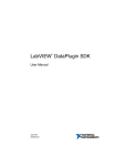
View the current active network configuration by entering “3” and pressing the Enter key.
Figure 1: EdgeWare Discovery Tool after Selection 3 is chosen.
Edgeware displays the current IP address, Broadcast address, and Subnet Mask of the CD Optical unit
(Figure 1).
Page 15
Step 3
•
•
Deactivate the DHCP and configure a static IP by selecting “2”.
You will be prompted to input the desired IP address, Subnet Mask, and the Default Gateway.
To re-activate the DHCP, simply select “1” from the list of options and the CD Optical unit will
automatically drop all the static IP information, and then a network restart will give it an address from
the DHCP server.
USE OF THE SERIAL NUMBER FOR A NAME SEARCH
The serial number can be used to get a name for the Storage Server.
1. Note the serial number on the back of the unit. The format is CExxxxxx-x.
2. Open an internet browser on a workstation on the same subnet as the EdgeWare system.
3. Type in the URL: https://[CExxxxxx]:10000 (where CExxxxx is the serial number with hyphen and
last digit omitted) or URL: https://IP address:10000 with the IP address assigned from DHCP.
You can find the IP address from your DHCP server leases by matching the MAC address of the
unit. The digits from the 3rd digit till the 9th digit, in the unit serial number specify the last 6
digits of the MAC address of your unit.
4. Login to the EdgeWare web based UI with default username ‘admin’ and password ‘setup’.
BONJOUR (OS X DISCOVERY VIA ZERO-CONFIG) VIA AN OS X CLIENT:
It enables the discovery of the servers on a Macintosh client. Its requirements are stated below:
• Allocate IP Address without a DHCP Server.
• Locate services without the use of directory server.
• Translate between names and addresses without the DHCP Server.
UPNP VIA A WINDOWS XP OR SIMILAR CLIENT
•
•
UPnP allows discovery of servers on XP and other Windows-based clients. UPnP discovery
protocol allows the server to advertise its service to a control point of the network. The control
point searches for other servers on the Network and discovers them.
UPnP Service in Windows can be located/installed in the following manner:
i. Go to Add or Remove Program under control panel.
ii. Hit Add/Remove windows component.
iii. Select Networking Services and hit Details.
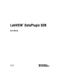
iv. Put a check on UPnP User Interface and hit ok to install (Figure 2).
v. Open Services.msc under Start->Run and ensure that SSDP Discovery Service is started
(Figure 3).
Page 16
Figure 2: Installing UPnP in Windows XP.
Figure 3: Locate SSDP Discovery Service under services.
UPNP NETWORK DISCOVERY VIA A WINDOWS VISTA CLIENT
•
•
•
•
In Windows Vista, uPnP has been renamed “Network Discovery.”
Windows Vista Network Discovery (uPnP) discovery protocol allows the server to advertise its
service to a control point of the network. The control point searches for other servers on the
Network and discovers them.
Normally, Network Discovery works automatically as described above in “Set Client IP Address
and Netmask on Microsoft Vista.” If not, it can be activated as described below.
Network Discovery in Windows Vista can be located or activated in the following manner:
i. Select the Windows icon in the lower left corner of the screen.
ii. Select Control panel.
Page 17
iii.
iv.
v.
vi.
Select Network and Internet.
Select Network and Sharing Center.
Find Network discovery, and check whether the “on” dot is marked.
If not, click the large dot with the v in it to expand Network discovery, and click Turn on
network discovery.
• Network Discovery, once activated, is used in the following manner:
i. Select the Windows icon in the lower left corner of the screen.
ii. Select Control panel.
iii. Select Network and Internet.
iv. Select Network and Sharing Center.
v. Near the top, icons representing your network connections will appear. Double-click the one
that represents the network or connection containing the EdgeWare Server.
vi. After a few seconds, a screen will appear with all the connected servers, including the
EdgeWare Server.
vii. Double-click the EdgeWare Server. It will bring up a browser and the IP address will be
apparent on the “Connected to” comment on the bottom of the screen. You can continue and
actually log in to your Server if you wish.
Please note that on a LAN the Network Discovery tool will also find other EdgeWare Servers and nonEdgeWare systems if they are present.
TROUBLESHOOTING STORAGE SERVER DISCOVERY
If you have another EdgeWare Server in your network, always try the NAS Servers Index.
Use another tool. Magellan has been known to work in cases where uPnP was unable to find an address,
for instance. A Magellan CD can be provided by Cutting Edge Technical Support if your original one
cannot be found.
If no Storage Server discovery tool works, try the serial number name search.
If the serial number name search does not work, and you are on a non-DHCP network or connection, try
the default Server IP address 169.254.5.58.
If there is still no result at this point, you are justified in returning to step B, “Troubleshooting a failed
server IP address creation,” in the preceding section of this manual.
Page 18
OVERVIEW OF THE EDGEWARE STORAGE SYSTEM
QUICK START WEB MANAGEMENT
Once the IP address is known, the GUI management interface is accessible to reconfigure the network
settings for your desired layout or to initialize the storage and network file services. The base for this GUI
is the popular Open Source Software (OSS) program called Webmin. Webmin provides a solid base
architecture and a means to leverage other work for the satisfaction of the customer. GUI adds many
custom storage management modules that allow quick and easy configuration with advanced features.
ACCESSING THE GUI
The EdgeWare GUI, like Webmin, uses port 10000 for web browser access and discovery UDP
broadcasts. Once the hostname or IP address is known using discovery tools or Domain Name Services
(DNS), the GUI is accessible from any web browser by the URL, https://[IP address]:10000/ or
https://[hostname]:10000/. Initial access is by user admin and password setup. Figure 4 shows a web
browser URL consistent with using HTTPS and port 10000.
Figure 4: GUI HTTPS and Port 10000 access line.
Webmin is organized as a tree: start by selecting a section (top row of icons), then a module (left side),
then continue by selecting component and even deeper features if necessary until reaching the page you
need. To back out closer to the trunk, you normally either do an input or change, or select “Return to
Index” which is found near the bottom of the page. (Sometimes scrolling down is necessary if the page is
too big to fit on the screen.) That backs you out one or more levels, possibly up to module. To change
modules or sections, select the corresponding icon.
NAVIGATING THROUGH THE USER GUIDE
In this user guide or manual, navigating to topics mirrors the GUI layout where sections and
management modules, or modules for short, define an outline or management tree. The modules are
shown on the left-hand side of your web browser when accessing the GUI, and the sections are on the
top. The modules are the base unit of deploying or removing additional management features. Inside
each module are management components, or components for short, typically many of them. The
convention of grouping modules in sections is a convenience to create a tree layout of related modules.
The resulting management tree is an outline to this guide as well. All the topics in this manual are
organized in the six sections corresponding to the GUI and summarized below.
Page 19
Some feature deployments, such as Failover for example, are complex enough to require action in several
sections. Each of these complex deployments has a lead section (in Failover’s case it is Clustering). Such
a deployment guide is found in its lead section in this manual, and the description is organized
constructively, by steps with checks, to map the necessary progress through other sections. You have
already encountered such a constructive guide (with steps A, B, and C) in Connecting to EdgeWare
Servers for the First Time, above.
SERVER SECTION
The Server section includes modules for System Time, (Webedge) Management, and (GUI)
Administrators. Selecting the Server link, Server, with the closed folder icon next to it, expands the Server
section. After expansion, the Server section opens up the folder icon and lists the modules affiliated with
this section. The links are an indented list of module names as hyperlinks which can be selected using the
mouse.
STORAGE SECTION
Enclosed in the Storage section are the modules: RAID (Software and Hardware), Volume Manager,
Share Manager, Quotas, Backup (disk and tape), and iSCSI.
NETWORKING SECTION
The Networking section includes the modules for the (IP address) Network, (share management for)
Remote Replication, and the file sharing protocols CIFS, NFS, AppleTalk, FTP, and Http. These are
protocols for which EdgeWare Storage Server acts as a server.
AUTHENTICATION SECTION
The Authentication section includes the modules for: Users and Groups, Share Permissions, NIS, and
LDAP. NIS and LDAP are protocols for which EdgeWare Storage Server acts as a client.
MAINTENANCE SECTION
The Maintenance section includes the modules: Shutdown (and reboot), Monitoring, Logs, (lists of
running) Processes, Command Line (access), (OS) Integrity, and (software) Updates. Integrity also
includes the important capability of configuration backup.
CLUSTERING SECTION
The Clustering section includes the modules: NAS Servers Index, Remote Replication (Asynchronous
share mirroring), IP Failover, and Remote Mirroring (Synchronous volume mirroring). The last three are
complex deployments involving several steps.
NOTE: Every parameter/option needed by GUI and the EdgeWare OS is case-sensitive.
Page 20
SERVER SECTION
This is the first section that comes up when you enter the EdgeWare UI. It offers server information,
RAID information, and volume information that are current at the time the page appeared. Hitting
your browser’s reset button will cause this page to reappear with newer information. Navigating by
picking module selections (on the left side of the screen), even module selections from the Server
section, will cause the page to be replaced by other modules’ main pages. To make the initial page
reappear, select the triangle that is in the upper left near EdgeWare on your screen.
SYSTEM TIME MODULE
In this module you can set the time and the date for the system and the real time clock (hardware time)
by making selections from the drop down menus.
Figure 5: System Time setting page.
System Time refers to two different time settings; both can be configured to synchronize with a Network
Time Protocol (NTP) server. They are shown as one, except that the hardware clock is mentioned. The
two differ in that the system time lives in software only as long as the operating system is active (i.e., as
long as the server is powered on and the Linux OS is active). The hardware time is the reflection of the
hardware, NVRAM BIOS time. Figure 5 shows the System Time UI.
Page 21
Synchronization of time is important not only for keeping track of actual dates and times on files but also
for proper mirroring and clustering setup. In a cluster, even a simple mirroring cluster of two, time
differences may keep the proper things from happening or, at least, happening as expected. This is
where NTP servers are most useful.
You can specify a network time server on this page for synchronizing the system and/or hardware time
with that time server. You can find a list of public NTP servers at the website mentioned below:
http://ntp.isc.org/bin/view/Servers/NTPPoolServers
MANAGEMENT MODULE
This module provides management options for configuring access and settings for the web UI. There are
four sub-sections under this section:
Figure 6: Management module main page.
IP ACCESS CONTROL
•
•
•
•
Here you can control access to the web UI based on IP information of client machines. Select
your choice of the three access modes and enter the IP addresses in the text area.
If you want to restrict or allow clients from a particular subnet then the format to enter a subnet
is: <IP address>/<subnet mask>
For instance if you would like to block or allow the 192.168.0.0 subnet, enter:
192.168.0.0/255.255.255.0
If you wish a reverse name lookup to verify the IP address has a hostname (and vice-versa), you
should select the check box below the entry box. Selecting the check box enforces reverse name
lookups.
LANGUAGE
Display the Language for the EdgeWare OS which is English as default.
Page 22
SSL ENCRYPTION
Here you can create SSL keys for you server. Enter the requested information in the text fields and click
on Create Now.
CERTIFICATE AUTHORITY
To set up your Certificate Authority (CA), enter the CA information and paste the certificate given to you
by the CA.
ADMINISTRATORS MODULE
This module provides the functionality to create administrative users and groups for the web UI. These
administrative users are different from, and more powerful than, the standard users dealt with in the
Authentication section further on in this manual. This module also offers the administrator the capability
of viewing the current logons and administrative changes.
GUI ADMINISTRATIVE USERS
This component contains access control configuration for the GUI user interface administrative users.
Inside the Administrators module, the administrative users and groups have pull down list boxes directing
the page to list the selected member’s module access list. You can then select to edit the GUI
administrators properties using the hyperlink ‘Edit User’. You then can select a higher level of security
using the select list next to Password as shown in Figure 9.
If you wish to keep the GUI root administrator in place and want the password synchronized with the
SSH (secure shell) access from other systems, then select Unix Authentication for the Password
parameter. The new password is now the default Unix Authentication password, 4linux! If you wish to
keep the GUI root administrator's password separate from the SSH and UNIX password then select ‘Set
to...’ and enter a new value. You must then select Save at the bottom of the page (not shown in Figure
9) to apply your selection.
Under each administrative user configuration page as show in Figure 6, you can also restrict or allow
access to a web UI administrator for each configurable module in the UI by clearing or checking the
check box next to each module name. Alternatively, the other recommended path is to add a new GUI
user, say ‘administer’. This administrator does not have to be a local User on the EdgeWare system but
can exist solely for administration through the web browser.
One does not need to delete the default admin administrator, though it is a good idea to change its
default password, setup. The root administrator is not accessible by browser, but has access to certain
extra modules and should also not be deleted.
Page 23
Figure 7: GUI root administrator details.
GUI ADMINISTRATIVE GROUPS
This component provides the functionality to create administrative groups for the web UI. You can create
groups and then add the administrative users you create under GUI Users to specific groups by selecting
the group in ‘Member of group’ when enter the click ‘Create a new GUI User’ as shown in Figure 7. You
can use GUI Groups to create administrative users quickly with module access control specified in the
GUI group, so that you do not need to select or unselect the modules when you create each user. See
Figure 8 and Figure 9.
The normal use of groups is to define a subset of the modules list that an admin of this group can deal
with. The example of Figure 8 and Figure 9 is meant to deal only with quotas and a few related modules
such as shares. Note that when the user created in this group is expanded, its access rights do not even
show quotas: you must expand its group before you can modify these access rights, and then they are
modified for every user in the group.
Page 24
Figure 8: Create GUI Group.
Figure 9: Create GUI User and make it a member of a group from ‘Member of group’.
Page 25
VIEW LOGIN SESSIONS
Here you can view all the current logons made by administrative users of the UI and also the
configuration changes made in each login session so far (Figure 10).
Figure 10: Viewing current login sessions.
You can view the logs recorded for a session by clicking ‘View logs’ hyperlink on the right of each session.
To disconnect a session, click on the Session ID hyperlink of each session.
Page 26
STORAGE SECTION
The primary use of the EdgeWare Storage system is for ‘block’ or file storage. There are four primary
configuration steps to allow access to disk storage space:
1) Configure the RAID set (typically done at install).
2) Make a partition on the physical disk if required in Partitions.
3) Virtualize the storage with the Volume Manager and create logical volumes.
4) Export the logical volumes using the Share Manager (NAS), or activate a target (iSCSI).
The term mass storage, or storage, is customarily used to mean very large disk array space, typically
at least hundreds of gigabytes, that is completely available to the customer to configure for use of
systems outside the EdgeWare Server. Other, much smaller disk space is required for the EdgeWare
Server itself, its operating system, logs, authentication files, and so forth. This system disk space should
be thought of as separate.
SCREEN RESPONSE
Storage operations controlled by the EdgeWare UI often require most of the server’s capability for an
extended period of time, especially when they are starting and finishing. Because of this, screen response
may be slow. Allow several seconds, or even up to a minute, for screen response to major creation
and deletion operations such as RAIDs or volume groups. Even updating a changeable screen (such as a
screen that shows percent completion) may take ten seconds or more, because the screen must wait for
a pause point in the heavy CPU and disk operations of initializing the resource.
If a screen goes blank or gray, or does not seem to respond to a change, this may be a normal response
to the delay discussed in the previous paragraph. Do not interrupt the ongoing operation. If it takes
more than a minute to respond, contact your organization’s technical support.
Page 27
RAID MODULE
The recommended mode of use of the physical disk storage, whether internal or external to the
EdgeWare Storage system, is to be organized in a RAID set. RAID increases reliability and often improves
performance depending on the usage model (discussed with the Volume Manager module).
EdgeWare OS supports up to four types of RAID configurations for the storage arrays. These RAID levels
can be used on a multi-drive appliance, whether or not a hardware RAID card is installed. If there is no
hardware RAID card installed, you can use software RAID. It is important to note that for a two-drive
appliance, the only RAID levels available are 0 and 1. For an appliance with three or more drives, RAID
levels 0, 1, and 5 are available. At 4 or more drives RAID 6 also becomes available.
The RAID module contains two components: hardware RAID and software RAID. Generally EdgeWare
systems have hardware RAID controller(s). The RAID sets in this case are controlled by the hardware
controller(s). For one type of controller there is a component, ‘3ware Hardware RAID,’ which provides
information about the hard drives connected to the RAID controller, RAID sets and configuration options.
Another form of hardware RAID is the Xyratex controllers that export Fibre Channel devices. For such
systems there is a component, `Fibre Channel Arrays,’ which provides information and configuration
options for this kind of hardware RAID.
The ‘Software RAID’ component allows you to view, create and configure RAID sets via the operating
system. The lower end systems such as the 4i and Datacube do not have hardware RAID controllers, so
the only RAID type available is the software RAID. However, even when hardware RAID exists, you can
place software RAID on top of partitions from arrays you created by hardware RAID. To do this, first
select the `Modify Partitions’ bar and create the partitions.
SOFTWARE RAID
Important: If your appliance (even a Hardware RAID appliance) has mirrored system disks, these will
appear as SOFTWARE RAID and should not be disturbed as they are mounted in critical system locations!
Manipulate only mass storage with the software RAID tools described below. The Role of the “off limits”
disks is given as `SYSTEM DISK’ while for the ones open to reconfiguration it is `MASS STORAGE’ (see
Figure 11).
Cutting Edge EdgeWare OS supports four types of RAID configurations for the data partition. These RAID
levels can be used on a multi-drive appliance, whether or not a hardware RAID card is installed. If there
is no hardware RAID card installed, you can use software RAID. It is important to note that for a twodrive appliance, the only RAID levels available are 0 and 1. For an appliance with three or more drives,
RAID levels 0, 1, and 5 are available. At 4 or more drives RAID 6 also becomes available.
Page 28
RAID 0: Single Large Volume: This type of RAID is also referred to as
striping. RAID 0 interleaves blocks of data between several drives. Even
though multiple drives exist in the array, to the user a RAID 0 appears as a
single large volume. It is important to understand however, that there is no
form of data backup when using a RAID 0. If a single drive fails, you will
lose the entire array. This type of RAID should not be used for mission
critical data. RAID 0 is available for any system with two or more drives.
RAID 1: Mirroring: This type of RAID is used to create a mirror copy of
the information contained on one or more of the disks. In this method, a
mirror is created for each drive containing data. For example, in a two drive
RAID 1 setup, both drives contain the exact same data. Since there is 100%
redundancy, there is no risk of losing data if one drive fails. RAID 1 is
available for any system with two or more drives.
RAID 5: Disk Striping with Distributed Parity : This type of RAID
features both striping and redundancy. This type of RAID uses a technique
called distributed parity, which allows data to be recovered if one drive in
the RAID fails. In addition, data blocks are interleaved evenly across the
drives in parity bits. RAID 5 is only available for systems that have three or
more drives.
RAID 6: Disk Striping with 2 Independent Distributed Parities:
This type of RAID is an variation of RAID 5 which allows for additional fault
tolerance by using a second independent distributed parity scheme (twodimensional parity). Data is striped on a block level across a set of drives,
just like in RAID 5, and a second set of parity is also calculated and written
across all the drives; RAID 6 provides for an extremely high data fault
tolerance and can sustain 2 simultaneous drive failures. Minimum drives
required for a RAID6 is 4 or N + 2 where N is the number of desired usable
drives.
Software RAID is widely used in Linux storage servers and is very reliable. The software RAID is available
for providing additional reliability when adding external SCSI drives or a JBOD disk set. After selecting the
software RAID icon in the RAID module, the administrator can view all existing software RAID sets which
are also listed inside the /proc/mdstat file where the Linux kernel tracks RAID sets. Figure 15 below give
an example of software RAID sets created from partitions on drives connected to standard IDE and SATA
controllers (SATA drives show up as SCSI drives in Linux systems).
Creating a Software RAID Device:
To create a software RAID device, perform the following steps:
Page 29
1. Navigate to the RAID page under the Storage section.
2. Click on Modify Partitions button.
3. On the Partition Manager page, click on Add primary partition link for the drive you want to
include in a software RAID set. This should be a drive that has not been used in any other RAID
or anything else. Verify by going to the other options on the main RAID page. You can also check
Volume Manager which drives are already configured in volume groups and hence not usable for
software RAID until you delete those volume group structures.
For example, in Figures 11 and 12 below, SCSI devices A and B are separate mass storage arrays
(each presented by a hardware RAID card), and device C is the system disk, not mirrored. In
Figures 13-15, by contrast, you are modifying a system in which SCSI device C and SCSI device
D are the mass storage. The drives with location SCSI device A and B have the mirrored
operating system partitions, and the IDE device A is an unused DOM (solid state) drive (not
shown). Figures 16-17 come off a system with three mass storage arrays, and Figure 18 comes
from yet another system.
Sizes and extents are given in cylinders. Mass storage cylinders are always one binary
megabyte (1048576 bytes) long. System disk cylinders can vary, but are usually about 8 MB long.
Figure 11: Showing available SCSI devices A and B.
Page 30
4. After selecting `Add primary partition’ a page like Figure 12 appears. A partition using all of the
space of the drive is shown. You can change this. In Mass Storage partitions, the type is always
EFI GPT, but the size can be many terabytes. When satisfied with your Extent, hit Create.
Figure 12: Create Partition page.
5. Hit Return to Index, and create partitions for more drives in the same way, depending on what
RAID level you wish to create using them. Except for concatenated (linear) RAID,
partitions used in software RAID should always be exactly the same size, and should
always be on different disks.
6. When done, you hit Return to Index for the last time, and find yourself on the Partition Manager
page (compare Figure 11) and all your drives have red horizontal bars under Extent. Start and
End should have numbers, but Use and Free should be empty. Now hit Return to Index in that
page, and find yourself on the Software RAID page.
7. Use the drop-down list to select the type of software RAID to create and click on the create
software RAID device of level button. Shown in Figure 13 is the process of selecting RAID-Linear.
Notice four old software RAID devices: these are the mirrored system disks’ devices and they
should be left untouched.
Figure 13: Selecting type of software RAID level to create.
Page 31
8. Now select the drive partitions to include on the RAID device from the text box labeled Partitions
in RAID by pressing CTRL and mouse button as shown in Figure 14. Then click on create button.
Figure 14: Selecting disk partitions to include in RAID set.
9. The software RAID device should now be created as shown in Figure 15. Click on the link for the
software RAID device, in this case /dev/md4, and it will take you to its properties page.
Figure 15: Software RAID-Linear device created.
Page 32
Figure 16: Software RAID5 created.
10. When you first create the RAID device of level 5 or 6, the software has to generate the parity
and sync the drives. Figures 16 and 17 are from a different creation run, on a system that does
NOT have mirrored system disks. In Figure 17 you see a newly created RAID level 5 device
/dev/md0 is being synced and is currently at 0.1%. The RAID device is ready to be included in a
volume group and used as a logical volume in the Volume Manager right away, but performance
will be slower than normal, and there will be no redundancy or data protection, until the syncing
has completed. This could take several hours, even days, depending on the size of the drives and
the I/O on the system.
Figure 17: Software RAID level 5 device is syncing.
The ‘Percent of resync done’ value is for when the UI page was created, and does not update
automatically. Use ‘Return to index’ and cycle back to selecting the array’s device name for a
more current value. Note that response may be slow (see Screen Response subhead, above).
Page 33
11. Figure 18 is from yet another creation run, this time for a RAID1. It is what you get when the
syncing is not done and you click on the link for the software RAID device.
Figure 18: Software RAID1 details.
3WARE HARDWARE RAID
Note: The configuration for 3Ware Hardware RAID under EdgeWare 3.2 will only show for those Systems
which have installed 3Ware hardware.
In systems with 3ware hardware controllers, you can use hardware RAID to create redundant storage.
Older systems shipping out with hardware controllers had the Operating System installed on a hardware
RAID5 set configured from the factory. In this case you did not have the option to delete and recreate
hardware RAID since doing so would render the appliance unbootable. Current systems have the
Operating System residing on a local system disk or mirrored disk pair, or on a solid state disk or DOM.
This isolates the hardware RAID from the operating system dependency and gives flexibility and total
control of the hardware RAID storage to the customer. A local mirrored disk pair will appear as
SOFTWARE RAID and should not be disturbed as it functions as the system disk!
Page 34
Figure 19: 3ware devices summary page.
Figure 19 shows the summary page for 3ware in the case where no arrays have been created. If you
press “Start 3Ware Manager” you should get a confirmation screen that says “3dmd process successfully
started.” Hit Return to Index, which returns you to the 3Ware Hardware RAID page, then select a type of
RAID from the drop down list and press “Create Hardware RAID device of level >”. In the case of RAID1
the following screen appears:
Figure 20: 3ware RAID device creation page.
Normally, the Stripe Size (not present in Figure 20 because it is RAID1) need not be touched, and the
Storsave Policy is a tradeoff between speed and data stability in case of power failure. “Protect” is the
Page 35
most conservative, “Perform” the fastest, and “Balance” is intermediate. (The “Optimize 3ware” button on
the summary page has a similar function.) You must also pick the ports, using Ctrl or Shift to pick more
than one (shown selected). After making your selections, hit “Create.” A confirmation screen appears.
Exiting the confirmation screen, and selecting `Logical Disk 0,’ leads to the details of Figure 21. If a
3ware RAID set encounters a failed drive it will resync to a healthy state by using a hot spare drive, if
one is specified. If no hot spare was specified before a drive failed, you will have to replace the faulty
drive and then specify a rebuild of the RAID set. When a RAID set is not healthy and has suffered a drive
loss the status will change to ‘degraded’. The ‘Percent of resync done’ field shows the amount of RAID
rebuilding that has been completed. It is recommended that you perform maintenance, monitoring and
configuration of 3ware RAID sets from the 3ware manager. Refer to 3ware Hardware Monitoring section
below.
Figure 21: 3ware RAID unit 0 in detail; no hot spare disk present.
3Ware Hardware Monitoring:
RAID needs monitoring to avoid loss of data at times when the physical disks do fail. The 3Ware RAID
monitoring and configuration should be performed by accessing the 3ware web-based RAID manager:
1. Log in to the Storage Server web management at https://[Storage Server IP-address]:10000
2. Start the 3ware manager under Storage > RAID > 3ware Hardware RAID `Start 3Ware Manager’
(if it is already running the option displayed would be ‘Stop 3Ware Manager’).
3. Point your web browser to https://[Storage Server IP-address]:10001. Select Administrator
from the drop down list of users. Default password is amcc.
Page 36
NOTE: Only run the 3ware Manager when you have to perform configuration changes, for example RAID
rebuild, to the RAID sets. When done stop the 3ware manager.
Figure 22: 3ware Manager.
What to do first when a RAID set is degraded:
Sometimes due to heavy load or unclean shutdown a RAID set may kick out a member drive and cause
array degraded state. If a RAID5 array degrades and does not start initialization automatically after the
unit is running for 20 minutes you may have to re-introduce the kicked-out drive back into the RAID5
array. To do this:
1.
2.
3.
4.
5.
6.
7.
8.
Start the 3ware Manager from GUI.
Login to the 3ware Manager at https://[IP address]:10001 as Administrator.
Default password is amcc.
Go to the ‘Configure’ page.
Select the drive that has been kicked out of the RAID set.
Click on Remove Drive at the bottom.
Select the same drive again and click on Add Drive button below.
Next select any two of the healthy drives of the RAID set and also select the kicked-out drive
from earlier steps.
9. Click on Rebuild Unit button below.
10. RAID rebuild should start immediately. Go to ‘Home’ page to check the status of the rebuild
process.
Specifying a hot spare:
The RAID Controller(s) give you the option to specify a hot spare from one of your available ports. Hot
spares should be selected after RAID1 or RAID5 creation.
Page 37
To specify a hot spare:
1. While the system is running, install the spare drive to an empty tray from the chassis and insert
back. Make sure the blue LED on the tray lights up. If not make sure the drive tray is well seated
in the drive bay and the tray lever is fully closed.
2. Log into the 3ware manager.
3. Click on the check box next to the available offline port in 3ware manager on the Configure
page and then click on the Add Spare button.
NOTE: Hot spare drives must be equal to or larger than the drives used for the redundant array. If they
are even a few bytes smaller, they will fail.
In the Event of a Hard Drive Failure:
ALWAYS:
Verify the failed hard drive number
Before removing a hard drive, verify the location of the failed drive by checking the 3ware
manager alerts and logs on the Cutting Edge Storage Server. If an additional functioning drive
(other than the failed drive) is removed, data loss will result!
Typically, drives are counted left to right, then top to bottom, but this is not always true. Best is
to record the hard drive number outside its slot in advance. If there is any doubt, temporarily
unmount the degraded volume (logical array), or make it read-only, before experimenting with
drive removal.
Replace the failed drive and rebuild as soon as possible
A RAID 5 runs without protection while it is in degraded state. Allowing this state to continue
puts you in danger of losing another drive, causing data loss. If Auto Rebuild (Hot Spare) is
underway, wait for it to finish and then replace the failed drive with a new drive, and set that
new drive up as the new Hot Spare. If there is no Hot Spare, follow What to do first when a
RAID set is degraded above, except replace the failed drive with a new drive before step 7.
NEVER:
Remove more than one hard drive at a time
Page 38
In RAID 5 data protection modes, your Cutting Edge Storage Server device can continue
operating after a single drive failure per RAID 5 set. Do NOT remove any other drives from a
RAID set while there is a failed drive in the system or while the replacement drive is being
restored.
Auto Rebuild of Redundant Array:
If a hot spare is specified and the array degrades, an event notification is generated and the hot spare
dynamically replaces the failed drive in a redundant array without user intervention. Rebuild will
automatically be launched as background process and an event notification will notify the user when the
rebuild process is complete (if 3ware manager is running and e-mail notification is setup).
Replacing a hard drive in the Cutting Edge Storage Server:
In RAID5 and RAID1 configurations you can lose any single drive in each RAID set and still have data
integrity. In the event of a drive failure, you can quickly and easily replace drives without shutting down
the Storage Server. The Cutting Edge Storage Server system will automatically recognize and prepare
new drives.
Selecting Force Continue:
Selecting the Force Continue on Source Errors check box before rebuilding the array ensures rebuilds
are not terminated if ECC errors are detected on the source disk. Uncorrectable blocks will be rewritten,
but the data may be incorrect. It is recommended that a file system check be executed when the rebuild
completes. By default, this function is disabled. Select this option only if the initial rebuild has
failed.
Why can't I rebuild my hard drive in the Cutting Edge Storage Server?
Rebuilding a hard drive may fail for the following reasons:
•
The hard drive being used for the rebuild is damaged: Try using another hard drive.
CAUTION! Use Cutting Edge replacement drives only! Failure to do so will void your warranty.
•
More than one drive is damaged: Contact Cutting Edge for repairs.
FIBRE CHANNEL ARRAYS (XYRATEX RAID)
Page 39
Note: The configuration for Fibre Channel Arrays under EdgeWare 3.2 will only show for those Systems
which have installed Xyratex hardware.
In systems with Xyratex hardware controllers, you can use hardware RAID to create redundant storage,
just as with 3Ware. Older systems shipping out with hardware controllers had the Operating System
installed on a hardware RAID5 set configured from the factory. In this case you did not have the option
to delete and recreate hardware RAID since doing so would render the appliance unbootable. Current
systems have the Operating System residing on a local system disk or mirrored disk pair, or on a solid
state disk or DOM. This isolates the hardware RAID from the operating system dependency and gives
flexibility and total control of the hardware RAID storage to the customer. A local mirrored disk pair will
appear as SOFTWARE RAID and should not be disturbed as it functions as the system disk!
Before proceeding with the Xyratex RAID documentation below, please read the documentation above on
3Ware Hardware RAID. The advice there is applicable to Xyratex and other RAID, especially subhead “In
the Event of a Hard Drive Failure”. However, the 3ware Manager described above is replaced by
StorView, the Xyratex UI, which currently must be activated separately on your client, not through
EdgeWare.
Figure 23: Fibre Channel device summary page.
When you select `Fibre Channel Arrays’ in the RAID module main page, you get an icon with a long
identifier like 20000050CC204721 (page not shown). Select this and you get a page like Figure 23.
This puts you into the driver’s seat for generating arrays out of raw disks under the control of the Xyratex
controller. The techniques are very much like those for the 3Ware controller, described above.
After adding, deleting or changing any Fibre Channel arrays, be sure to reboot to make them visible to
other parts of EdgeWare. Fibre Channel storage is frequently shared between paired EdgeWare
CPU/motherboard units (heads) in failover arrangements. In such cases, also reboot the other head at
the same time.
Page 40
Figure 24: Fibre Channel device creation page.
Fibre Channel Array Creation and Deletion:
Select a type of RAID from the drop down list shown in Figure 23, and press ‘Create Fibre Channel Array
of level >’. In the case of RAID1/10 a screen like Figure 24 appears. The name has already been typed in
by the user, and the default selection of drives remains. Correct this and/or make other selections if
necessary. Then hit ‘Create’.
After a few seconds’ pause, a screen like Figure 23 should appear, but with the new array represented by
a new icon under ‘Fibre Channel Arrays’. Selecting this icon yields Figure 25. Notice that the device file
name is incomplete: the reboot, mentioned above, is needed before further progress can be made over
this array. Also notice that the Current status is Initializing, a process that can take hours for any RAID
level except RAID0.
Page 41
Figure 25: Fibre Channel Array “R1-array0” detail page.
To delete an array, reach its detail page as in Figure 25, and then hit the `Delete RAID array’
button. The delete will not succeed if any superstructure, such as partitions or dependent
software RAID arrays, still remains on the Fibre Channel Array in question. If that is a problem,
remove the superstructure and try again to delete.
Page 42
VOLUME MANAGER MODULE
Volume Manager is the heart of the storage management on the EdgeWare Storage Server. It provides
virtualization of physical storage. Using the Volume Manager you can create and aggregate storage
volume groups; add physical storage devices to these volume groups; create logical volumes and use
them for such purposes as file systems, iSCSI targets, and replication or mirroring targets; and create
snapshot volumes for the logical volumes.
USING THE VOLUME MANAGER FOR VIRTUALIZATION
The structure and terminology used here are standard for the Logical Volume Manager, a worldwide
cross-platform virtualization standard that is stable and robust. You can examine it by opening your
EdgeWare GUI to Storage > Volume Manager and moving around the tree found on that module page.
Outermost branch is the volume group, which is a big sequence of block-addressable storage, possibly
many terabytes. It is simply understood as room for a line of data, but it can grow and shrink, because it
is virtualized, or strung together, from a number of actual (physical) data storage devices. The volume
group is subdivided in two ways, which are independent of (orthogonal to) one another. They could be
thought of as ancestors and descendants.
The ancestors are physical volumes, which are block-addressable storage units used to build up the
volume group. They have to exist before the volume group can be formed. They can be added to or even
removed from an existing volume group. Usually they string together nose-to-tail, but they can be joined
in more obscure ways too, like striping. Even physical volumes are already abstracted: they are typically
the devices or “arrays” output by hardware or software RAID, not the individual hard drives from which
these are built.
The descendants are logical volumes and snapshot volumes, which are cut from the volume group
like partitions from a disk, and presented to the outside world as block devices with all the power that
block devices have. They can underlie file systems, can be iSCSI targets, and can be raw targets (as for
mirroring). The volume group has to exist before these can be made. Snapshot volumes are treated as
special, because they are not independent: each snapshot volume is related to a specific, pre-existing
logical volume, and aids in the snapshot feature, to be described later.
EdgeWare uses this enhanced volume management to virtualize the real, physical disks that exist on one
or more of the EdgeWare Storage systems. That provides the EdgeWare Storage system with the
flexibility to merge different or even dissimilar physical devices (e.g., iSCSI and local disks) into a single
pool of storage, to create block-level snapshots, and to easily shrink or extend logical volumes. When
using the Logical Volume Management through the GUI, this abstraction above the actual physical
storage creates a file or block based storage system that is able to accommodate changing size and other
requirements.
Page 43
Figure 26: Creating a new Volume Group.
CREATING A NEW VOLUME GROUP
To create a new Volume Group, click on ‘Add a New Volume Group’ at the top of the page. You will be
presented with Volume Group creation page as shown in Figure 26.
1. Type in a name (e.g. VGstorage) for the Volume Group.
2. Leave the Allocation block size default unless you need a specific block size for performance.
3. Select an initial physical device from the list; you can add more devices to the Volume Group
later. If you just created the physical device, especially if it is a RAID5 or RAID6, wait
several minutes for its initialization to get well underway.
4. Click on Create. The new Volume Group shows up expanded as in Figure 27.
Note: Screen response may be slow. If an error screen appears, give it a few minutes to initialize some
more, and try Steps 1-4 again.
Figure 27: Volume Group VGstorage is expanded.
Page 44
ADDING A PHYSICAL VOLUME
Your original Volume Group has only one Physical Volume. If this is not enough, you can now extend the
Volume Group by adding a Physical Volume.
1. Select Physical Volumes (add a physical volume) in the expanded Volume Group tree (see Figure
27).
2. Select the physical device from the drop-down list.
3. Leave “Enabled for allocation” on “yes”.
4. Click on Add to volume group.
Figure 28: Add Physical Volume to Volume Group VGstorage.
The expanded Volume Group tree will reappear, with both old and new Physical Volumes visible, not
necessarily in the order of attachment. To add more Physical Volumes, repeat this procedure. Physical
Volumes must be added one at a time.
It may seem odd that this particular Volume Group is now strung together from completely dissimilar
parts: an IDE DOM (solid state disk) only 1 GB long, and a big SCSI RAID-Linear array presented by a
3Ware controller. In fact, such combinations have value in certain high-speed scientific applications. This
is an illustration of the power of virtualization.
ADDING A LOGICAL VOLUME
Once enough Physical Volumes have been assembled into your Volume Group, the next step is to create
a Logical Volume. Your Volume Group is a generic line of storage. Your Logical Volumes will have specific
and usually different roles to play, even though they may come from the same Volume Group. This step
is very much like partitioning a disk.
Think ahead about how many Logical Volumes you are likely to need, and what they will be doing,
because once you allocate a size to a Logical Volume and build the superstructure that makes it useful to
Page 45
your storage users, and then permit it to be filled with real data, it is not easy to trim back or make room
for later needs.
Among the possible uses for Logical Volume space in the Volume Group are:
•
•
•
•
•
NAS protocols which offer File System storage to your users.
Asynchronous replication target which offers File System backup storage to an asynchronous
replication source on another system.
iSCSI target which offers block-level storage to your iSCSI initiator users.
Raw source or target for synchronous mirroring: the source is later built up in one of the
previously mentioned ways, but the target (on another system) is left raw, and should be the
same size as the source.
Snapshot Volume, which has a special relationship to a Logical Volume of one of the previous
types. It gets a separate tree branch and will be treated later in this manual. Remember to leave
room for Snapshot Volumes in the Volume Group if you are intending to use them, because each
Snapshot Volume must be in the same Volume Group as its parent Logical Volume.
After planning the use of the storage in your Volume Group, create each of your Logical Volumes in this
way:
1.
2.
3.
4.
5.
If necessary, click on the Volume Group to expand it.
Click on Add a Logical Volume.
You will be presented with a Logical Volume creation page.
Specify a name for the logical volume.
Give the amount of storage you want to allocate to the logical volume in Volume Size. ‘Storage
allocated from volume group (GB)’ shows the amount of storage that is in use and not available
for this logical volume. The default ‘Volume size’ number takes all the available storage. It is
usually NOT a good idea to take all the available storage, as that leaves no room for
unanticipated future logical volumes or snapshot volumes.
6. Select the file sharing protocol(s) in ‘Network File Protocol’ or combination of protocols you will
be enabling for the shares on this logical volume. Use CIFS in a Windows only network, NFS in a
UNIX variant only network, Mixed for multi-platform network or ISCSI to export the volume as an
ISCSI target. If your iSCSI initiator is Solaris, pick Solaris iSCSI Target.
7. If you have more than one Physical Volume, all identical, in the volume group under which you
are creating the logical volume, and if you wish for the speed advantage of striping (a RAID0-like
technique), select yes for ‘Stripe across physical volumes’. Figure 29 shows selected no for ‘Stripe
across physical volumes’ as the Physical Volumes in VGstorage are dissimilar. The default in this
selection, which is the alternative to striping, is concatenation or “nose-to-tail” stringing together
of physical devices.
8. Hit ‘Create’ (top of Figure 29).
9. Exit the confirmation screen (middle of Figure 29) with ‘Return to Index’. The result will be Edit
Logical Volume page with Logical Volume details (bottom of Figure 29).
10. Exiting the Edit Logical Volume page will show the Volume Manager page and the new Logical
Volume will appear in the tree (Figure 30).
Page 46
Figure 29: Logical volume LVstorage is created. Not all available storage is taken.
DELETING A LOGICAL VOLUME
In order to delete a logical volume you have to make sure that there are no shares defined on that logical
volume from Storage > Share Manager. In addition, if it is iSCSI, it must be removed from the iSCSI
Targets list in Storage > iSCSI. Any other uses such as asynchronous replication or synchronous mirroring
must also be disconnected. After this is done, proceed as follows:
1.
2.
3.
4.
5.
6.
7.
Expand the volume tree for the volume group containing the logical volume (Figure 30).
Click on the logical volume link.
An Edit Logical Volume page appears, with Logical volume details box (bottom of Figure 29).
Click ‘Unmount the logical volume’. A result announcement page appears.
Click on Return to Index. The Edit Logical Volume page returns, with Delete button (Figure 31).
Click ‘Delete’ on that page, and ‘Delete now’ on the resulting confirmation page.
Hit ‘Return to Index’ on the result announcement page, and your LV should be gone.
Page 47
Figure 30: Volume Manager page, with Logical Volume link.
Figure 31: Edit Logical Volume page, unmounted, ready to delete.
RESIZING A LOGICAL VOLUME
A logical volume under a volume group can only be resized to increase from its original size. Decreasing
the size of a logical volume is not possible. Also resizing a NAS volume requires its shares, but not its
Page 48
data, to be deleted after being backed up from Backup System Configuration in Integrity > Save and
Restore, and then restored after volume size has been increased. In the case of iSCSI volumes, the data
(not just the configuration) must be backed up and restored, a time-consuming process.
If you have already used up all the space in your volume group, as shown by two equal numbers in
Storage allocated from volume group (GB) (contrast Figure 31 which shows lots of room to
expand), then you must expand the volume group before performing the steps below. This is done by
adding a physical volume (see above).
The resizing procedure is as follows for a NAS volume:
1. Note share name(s); back up NAS shares configuration on the logical volume if necessary.
2. Delete all the shares on the logical volume (use Storage > Share Manager). This does not delete
their data. It will be found intact in step 14.
3.
4.
5.
6.
7.
8.
9.
10.
In Volume Manager expand the volume tree for the volume group containing the logical volume.
Click on the logical volume link.
You will be presented with an Edit Logical Volume screen (bottom of Figure 29).
Click ‘Unmount the logical volume’.
Click on ‘Return to Index’. Volume size is now editable.
Enter a new, increased size for the logical volume.
Click on Save.
A confirmation page appears (Figure 32), confirming this file system can be resized.
Figure 32: Resizing confirmation page.
11.
12.
13.
14.
Click on ‘Resize Logical Volume’. A result announcement page appears.
Click on ‘Return to Index’ on the result announcement.
Click ‘Mount the logical volume’. The logical volume is now resized and available for use.
Recreate the shares, from a configuration backup or other technique. The data is still there.
The resizing procedure for an iSCSI volume requires all initiators be disconnected and the iSCSI target
deleted (see documentation below for Storage > iSCSI module). Then steps 3 through 12 are done,
except 6 is unnecessary, as the volume will be found ‘Not in use’. After that, restore the iSCSI target in
Storage > iSCSI module, and reconnect via the initiator(s). Unfortunately the data does not reappear in
this case, and must be restored from backup.
SNAPSHOT VOLUMES
The snapshot facility of the EdgeWare OS allows the administrator to create a new block device which is
an exact copy of a logical volume, frozen at a point in time. One typical use is when some batch
Page 49
processing, a backup for instance, needs to be performed on the logical volume and you don't want to
unmount a logical volume on a production unit which has data being modified. Another use arises when
you want to have the option of accessing old data, even though you are expecting the data to change.
When the need for the snapshot is done, the system administrator can just remove it, without in any way
disturbing the parent logical volume. This facility does require that the snapshot be made at a time when
the data on the logical volume is in a consistent state. Many databases offer this capability.
The snapshot device is a read-only copy of another (parent) logical volume that contains all the data
that was in the parent at the time the snapshot was created. This means we can back up that volume
without having to worry about data being changed while the backup is going on, and we don't have to
take the volume offline while the backup is taking place. The Snapshot Volume, found in the Volume
Manager tree, is a logical block device that is needed to keep the snapshot device current. The snapshot
works by making a note, in the Snapshot Volume, of all changes in the parent, so that the snapshot
device can back out of the changes and recreate the original state whenever it is read. The bigger the
Snapshot Volume is, the longer the snapshot device can survive without overflowing, or filling up with
change data and becoming unusable. Even if overflow happens, the parent logical volume is unharmed.
DESIGNING A SNAPSHOT STRUCTURE
The snapshot facility of the EdgeWare OS allows freedom to the user, both to back up stored data in a
known, timed state, and to be able to recover older versions of the data. This freedom creates a burden
on storage and CPU resources when it is used. Therefore a design strategy is needed before the user
plunges into the deployment of a long-term snapshot structure. This strategy is based on knowledge of
the behavior of the snapshot machinery. Key facts include:
•
Snapshots randomize data writes. This impacts you if you are counting on frequently
writing big files (like movies) rapidly to EdgeWare storage – a situation called “long sequential
writes.” Although EdgeWare mitigates this as much as possible, by putting snapshot volumes on
separate physical volumes when it can, the snapshot mechanism causes much head movement
when writing, and even one snapshot can slow long sequential writes by a large factor.
EdgeWare tests (September 2008) showed these falling to around 6 MB/s. On the other hand, if
(like most customers) you are running a database or mail server, or other application that
randomly accesses data, one or two snapshots will not slow you much. Also, if you are mainly
reading files, even large files, from EdgeWare storage, snapshots will barely affect your speed.
•
Snapshots multiply data writes. If you are creating data, or changing very old data, then
every snapshot requires an extra write to its Snapshot Volume. One snapshot means two writes;
ten snapshots mean eleven writes. This affects even the random IO applications like databases
and mail servers. In EdgeWare tests (September 2008), database IOPS began to suffer
significantly after about four snapshots. Note that snapshots do not multiply reads, which are
little affected even by many snapshots. Thus, an approximate rule of thumb is IOPS(with
snapshots) = IOPS(without snapshots) / (1 + (proportion of writes)*(number of snapshots)). For
example, if 20% of IOs are writes, then five snapshots will approximately cut IOPS in half.
•
Snapshots heavily impact resources including storage and memory. This is true even if you
hardly ever write. This has several consequences:
Page 50
a. You must plan ahead for snapshot storage usage. The formula is: Minimum dedicated
snapshot storage = 2 * (Rate of file growth and change) * (Lifetime of snapshot) *
(Number of snapshots). The 2 is a safety margin; you may want more. Each snapshot
should get 2 * (Rate of file growth and change) * (Lifetime of snapshot) as its volume
size when it is being created.
b. Memory requirements enforce a practical maximum on the number of snapshots.
EdgeWare tests (September 2008) indicated an absolute limit of 15 snapshots. Software
changes currently under development are expected to increase this absolute limit to 50100, but that does not imply that a good design should go that far.
c.
Snapshot disk IO multiplies cache usage even if the practical maximum barrier of item
b above is not reached. This means that rapid IO right after bootup (or after a period of
quiet) can suddenly slow down after cache gets gobbled up. Observe snapshot behavior
over long periods of time (days) before concluding that it is satisfactory.
For a good snapshot design, built around these facts, you should take care to do the following:
•
Predict behavior before committing to storage allocation and snapshot scheduling. The numbers
and formulas above will aid you, together with your own installation’s information about peak
data creation and change rates and IOPS. Cutting Edge personnel can aid with these predictions.
•
Precisely define your snapshot needs, and discard unneeded or aging snapshots immediately.
This is partially automated through EdgeWare’s snapshot schedule and Maximum Concurrent
Snapshots (Lifetime = (Job Schedule) * (Maximum Concurrent Snapshots)). However, an
administrator should be tasked with checking and cleaning up snapshots, at least weekly.
•
Progress the data offline so as to minimize needed snapshot lifetime. See “Designing a Backup
System” below in this manual, and make use of the efficient EdgeWare capability of
Asynchronous Replication.
CREATING A SNAPSHOT OF A LOGICAL VOLUME
Figure 33: Creating a snapshot volume of a logical volume.
Page 51
A snapshot volume can be as large or a small as you like but it must be large enough to hold all the
changes that are likely to happen to the original volume during the lifetime of the snapshot. Snapshots
affect the performance of logical volumes, so create snapshots sparingly. When automating snapshot
creation with ‘Scheduling Snapshots’, always enter a ‘Maximum Concurrent Snapshots’ value to limit the
number of snapshots at one time.
1. Expand the Volume Group which contains the logical volume you want to snapshot.
2. Click on Add a snapshot volume hyperlink.
3. You should get the Create Snapshot Volume page as shown in Figure 33. Enter a snapshot
volume name. This is a new name, not the name of the parent volume you want to snapshot.
4. Enter the snapshot volume size. This should be large enough to hold any increase in size, or
other change, of the parent logical volume during the lifetime of the snapshot.
5. Select the logical volume that will be the parent or source of the snapshot.
6. Click on ‘Create’ to instantly create the snapshot or click on ‘Schedule’ to automate snapshot
creation based on a schedule.
SCHEDULING SNAPSHOTS:
If you click on ‘Schedule’ on the Create Snapshot Volume page you are presented with a Schedule
Snapshot Creation page as shown in Figure 34.
Figure 34: Snapshot creation scheduling.
1. Enter your choices for the options:
Enable Snapshot Scheduling? This checkbox allows you to select whether this scheduling should be
active or not. ‘No’ means it will get recorded and you can activate it later. ‘Yes’ means it is recorded and
active now.
Page 52
Maximum Concurrent Snapshots: The scheduler will not exceed this number of active snapshots at
one time. It kills the oldest when needed to ensure this. Always enter a reasonable, small number
here.
Notification Email: This email address is where email notification is sent when snapshots are created.
Reminder Notes: Text here is sent out in the email notification or entered in the GUI log entries for
scheduled snapshots.
2. Next enter the schedule for the snapshot creation, using the pull-down list at ‘Job schedule’.
3. Select ‘Create’ if you want to just make the schedule, or select ‘Create and Snapshot Now’ if you
want to trigger a snapshot right now AND make the schedule. Whether making the schedule
actually causes regular snapshots to start happening depends on what you selected for ‘Enable
Snapshot Scheduling?’ above.
EDITING AND MOUNTING SNAPSHOTS AND EDITING SNAPSHOT SCHEDULES
Figure 35: Snapshot slice from Volume Manager page.
The slice above from a Volume Manager page shows how two snapshots and a snapshot schedule appear
in the Volume Group’s tree. This was generated by selecting ‘Create and Snapshot Now’ in step 3 above.
Names ending in _schedule are not Snapshot Volumes, but snapshot schedules. Among the two actual
Snapshot Volume names, the short one was the immediate snapshot made by ‘Snapshot Now’ and the
long one, with the timestamp-number 1219282202 terminating it, is one created by the scheduler. The
timestamp number tells how many seconds after the Epoch (00:00 Jan 1, 1970) the snapshot was made.
Selecting a snapshot schedule link brings up a snapshot schedule editing page, looking much like Figure
34, except ‘Delete’ is also an option. Deleting a snapshot schedule does not delete the snapshots it
created, but it does prevent any more snapshots from being created by this schedule. Similarly, a
schedule that was merely recorded by selecting ‘No’ for ‘Enable Snapshot Scheduling?’ can be triggered
into action by changing that to a `Yes’ and hitting `Create’ or ‘Create and Snapshot Now’.
Selecting a snapshot link (one of the ones that do not end in _schedule) brings up a snapshot editing
page. This is very much like the snapshot creation page of Figure 33, except it allows `Delete’, and it also
allows the snapshot to be mounted. Unlike regular Logical Volumes, snapshots are NOT mounted by
default. For them to be useful, you have to select them and mount them in this page.
Page 53
DELETING SNAPSHOTS
Snapshots require attention. If a snapshot is no longer serving a useful purpose, delete it. If a snapshot
schedule has outlived its usefulness, delete it and then delete the snapshots created by it. Aging
snapshots take up precious storage space, they slow down their parent Logical Volumes, and they have
an annoying tendency to overflow.
Hint: In some applications, large numbers of snapshots are created by a schedule. After deleting the
schedule, it is time-consuming to delete the snapshots one by one. A convenient method for deleting
them all at once is to create a new snapshot schedule for the same parent volume, with maximum count
1, activated but with no snapshot now. This will remove all but one of the snapshots generated by the
old schedule. The process can take a few minutes. Then you can delete the last snapshot and the new
schedule too.
Page 54
SHARE MANAGER MODULE
Creating and managing NAS shares is done via the Share Manager. You can share a specific folder in any
mounted logical volume created in the EdgeWare Server, and make it available to users on the network.
When you create a share, you can assign permissions to the share for any of these users, who will then
be allowed or denied specific operations when they access the share over the network. Here users
usually refers to network users, as dealt with in the Authentication section, rather than administrative
users as dealt with in the Server > Administrators module. The exception to this is Networking > Http.
Shares are not used by iSCSI volumes.
CREATING AND EDITING A SHARE
Figure 36: Creating a network share.
1. Under Share Manager click on the link ‘Create a new share’.
2. Specify a Share name (see Figure 36).
3. Select a volume or directory to share by clicking the browse button. A pop up window should
appear after a few seconds, listing the available volumes (Figure 37).
4. If you need to select a particular directory under the volume double click the volume link to go
deeper into the volume tree.
5. Press OK to confirm your selection.
6. You can write a brief description of the share under ‘Share Comment’.
7. Select the network file protocols that you want to enable for the share. Disabling the protocols
you will not need improves efficiency and security, and more protocols can be added later by
editing the share. See list below.
8. Click on Save to create the share.
Page 55
Figure 37: Choose volume pop-up window.
Options available in Step 7:
CIFS: Microsoft Windows Common Internet File System (enhanced version of Microsoft’s SMB).
NFS: Network file system developed by Sun Microsystems, and native to Unix variants like Linux.
APPLETALK: Apple’s network file system, including resource forks.
FTP: File Transfer Protocol.
HTTP: Hyper Text Transfer Protocol for administrative users.
ASYNC: Asynchronous replication source.
The first three items in the above options list are not exclusive to the operating systems mentioned. For
instance, CIFS can be accessed by Linux clients, and NFS can be accessed by Windows clients. Each of
these protocols is friendly to certain styles of authentication and permissions that are most prevalent on
its native clients. For more details see the Network section below.
Once the share exists, it will be listed in the table in the Share Manager module page, and can be edited.
Use of the share requires further setup in the Network or other sections.
Page 56
QUOTAS MODULE
A disk quota defines the maximum amount of hard disk space allowed for a user's files. There are two
quota limits: the hard limit and the soft limit. The hard limit defines the absolute maximum. When the
hard limit is reached, the system will not allow a user any more space. This effectively stops you from
using that EdgeWare user account to create new files, edit old files etc. The soft limit is the desired
maximum. After exceeding the soft limit, the system warns the user and starts a grace period. When the
grace period ends, the system will not allow the user any more space.
Figure 38: Quotas page.
Figure 39: Filesystem Quotas page for Users.
Page 57
MANAGING DISK QUOTAS
1. To manage disk quotas for users or groups click the relevant link under the file system column
for the Volume you want to manage quotas for.
2. This will lead you to the file system quota page for that logical volume. Here you can set hard
and soft limits for users on the volume. Clicking on the button ‘browse’ will give you a pop up
browser window where you can select a user to specify quotas for.
3. After you have selected or entered a user in the test box, click on ‘Edit Quotas’.
4. The next page (Figure 40) lets you specify the hard and soft limits for the user. You can specify
limits based on number of blocks (where 1 block here is approximately equal to 1 Kilobyte)
and/or on number of files owned by the user.
5. When you are done click on ‘Update’ to apply the changes.
Figure 40: Adding quota for a user.
If you want to copy quota limits for the user you just specified to other users:
1.
2.
3.
4.
Click on Edit User Quota for the user from the Quota page.
Click on List All Quotas.
Click on Copy Quotas.
Select one of the options on the copy quotas page (Figure 41).
Adding and copying quotas for groups:
Adding and copying quotas for groups work the same way as they do for users.
Page 58
Figure 41: Copying quota settings of a user to other users.
QUOTAS FOR NEW USERS AND GROUPS
You can also specify quotas which will be enforced on any new users and groups that will be created
later on the system. Enter the relevant values in the New User Quotas area near the bottom of the
Filesystem Quotas page shown in Figure 39.
BACKUP MODULE
Backup allows you to back up your data in the logical volumes to another volume in the system or to a
tape device. If your system has a tape drive or tape library connected you can back up your data to that
device. Otherwise you can only back up to another logical volume.
This backup module operates in two directions: backup, which saves a copy of a logical volume, or
restore, which copies over a logical volume with data from a previous backup.
DESIGNING A BACKUP SYSTEM
Backups serve two purposes:
•
•
Recovery from catastrophic data loss.
Storing old versions of your data so you can revert to them if necessary.
For either of these to work, you must apply the first principle of backup design: See to it that an
event that takes out your current data is unlikely at the same time to take out your backup. This not only
includes hardware failures, but software and user errors.
Alternative approaches that satisfy the first principle of backup design can include:
Page 59
•
•
•
Use different media (for instance, magnetic tape backup of disk-based storage) and/or offsite
storage.
Use a physically separate storage system (see Asynchronous Replication, in Network and
Clustering sections below).
Use different disks on the same system (the backup to another logical volume). Notice that in
this case it should not only be another logical volume, but also it should be on another volume
group that is built from a different set of physical volumes.
Because software and user errors are at least as common as hardware failures, it is important, especially
in the last option, to make sure that the normal uses of your current data – especially uses that can write
or delete that data – do not at the same time do the same thing to your backup data. The backups
should have different-looking names and not be available for global operations. EdgeWare’s volumegroup-based tree structure is your friend in this requirement, but you must also set up your normal
procedures to avoid inadvertent backup destruction.
In addition, your procedures need to ensure the second principle of backup design: See to it that the
backups actually get made on a regular basis. Once again, EdgeWare does its part with its scheduled
backup capability, but there are other parts of the design that only you can contribute. These include
physically enabling backup flow, with media, shelf space, transportation off-site, and for some operations
even regular replacement of whole systems. But they also include virtual backup support, such as a policy
for backup naming and placement of the necessary backup volumes on storage.
Finally, the third principle of backup design is, as far as possible, to make a current copy before
restoring from backup. EdgeWare supports this through the “Live Copy” and “Backup Now” capabilities.
Your job is to make sure there is space to place them, and a well-known policy to do this. If your current
data is utterly destroyed, then no such copy is possible. But it is much more common that a part of your
data has been messed up, a version overwritten, or somebody’s work lost. The steps to a safe restore are
then:
1.
2.
3.
4.
Determine exactly what the restore is going to cover.
Make a copy of that part of the damaged current data, and place it in a safe place.
Do the restore over the data area determined in step 1.
Compare the results of your restore with your knowledge of the original current data.
It is entirely too common that a restore does far more damage than the original data loss. Don’t let it
happen to you!
ADDING A NEW BACKUP OF A VOLUME
To start a new backup:
1. Select the logical volume you want to backup from the drop down menu as shown in Figure 42.
Page 60
Figure 42: Backup.
2. Click on ‘Add a new backup of a volume’ button. You should get the page shown in Figure 43.
Figure 43: Add a new backup of a volume.
3. In the ‘Backup to’ text field select the backup target you want to use. Select:
-
Tape: To backup to a tape device in the system.
-
Tar file: To backup to a file on another logical volume.
-
Another Volume (Live Copy): To backup files to another logical volume.
Page 61
4
5
6
7
6.
7.
8.
9.
For Tar file or Live Copy, above, select a directory from the drop down list.
For Tar file, you must add a file name to the directory. Click on the text window, move the cursor
to the end of the directory name, and type in something like /20080826-LVstorage-backup
where in place of “20080826-LVstorage” you place some identifier of the source and
date/instance of backup. Do not terminate the name with a dot-suffix like “.tar” or “.tgz”. The
restore program can recognize the format.
For ‘Make multiple volumes of the tape size’ select Yes if the size of your data is more than a
single media and you have to span the backup over more than 1 media. To span the backup on
multiple media you will have to manually label the media to keep track of the order in which the
backup will be written. During the backup process once a media becomes full with data the tape
drive will eject the media out. At this point you have to remove the media and insert another
empty media. Once another media is inserted the backup process will proceed and so on till all
the data has been backed up.
Give a name to the backup job for ‘Label’.
Choose to specify the ‘Tape size’ or let Backup process calculate by querying the tape drive.
‘Block size’ value should be default unless you have a specific block size you want to enter.
Select yes for ‘Software Compression’ only if compression is desired when backing up to Tar file.
Click on ‘Continue’.
In Figure 44, you can specify a schedule for this backup to run on. If you do not want to specify a
schedule right now you can click on ‘Create and Backup Now’ to start the backup immediately. By editing
your backup, you can later add, change, or remove the schedule.
Figure 44: Specify a backup schedule.
SCHEDULING BACKUP
In Figure 44, you can specify a schedule for this backup to run on. By editing a backup that was made
without a schedule, you can later specify a schedule also. Proceed as follows:
Page 62
1. Enable backup schedule from ‘Scheduled backup enabled?’ at the top.
2. Select the interval at which backups are to be made from the drop-down list.
3. Click on ‘Create’ to save the backup job schedule.
RESTORE
To restore from backup:
1. Select the backup target you want to restore from. For tape, insert the correct media or the first
media of the media group (Figure 45).
2. Select the location to restore the backup. Click the browse button next to the ‘Restore to
directory’ text box, a pop window will appear where you can select from available and valid
locations.
3. Next select ‘Everything in backup’ to restore all the data in the backup or select ‘Listed files’ to
restore specific files. If you select the latter option, make sure that the filenames are separated
by a space and that the filenames must be relative to the file system that the backup was made
from, so if you backed up /home and wanted to just restore /home/foo you would enter foo into
this field or if want to restore a file foo in a directory /home/bar you would enter /bar/foo.
NOTE: By default the restore process will not overwrite a file when a matching file is present on
the volume being restored that is newer than the file in the backup.
Figure 45: Restoring a backup.
Page 63
4. If the backup was spanned across multiple files or tapes then select yes for ‘Backup is split across
multiple files/tapes?’
5. Select yes to ‘Show list of files only (for test)’ if you just want to view a listing of files in the
backup. This will not restore data.
6. ‘Extra command-line options’ should be left blank.
7. Click ‘Restore Backup Now’, this will start the restore process or print out a listing of files in the
backup if selected in step 5.
8. If your backup is on multiple media the tape drive will eject the media when it is ready for the
next ordered media in the backup media set. Just insert the next media and the restore process
will continue automatically.
9. When the restore process is complete you will get a message ‘Restore completed successfully’ on
the page as shown in Figure 46. (Note: Figure 46 is from a tape backup, not the Live Copy
backup set up in Figures 42 through 45.)
Figure 46: Restore Backup result.
ISCSI MODULE
iSCSI is Internet SCSI (Small Computer System Interface), an IP-based storage networking standard for
linking data storage facilities. By carrying SCSI commands over IP (Internet Protocol) networks, iSCSI is
used to facilitate data transfers over intranets and to manage storage over long distances.
The iSCSI protocol takes advantage of the fact that anything that uses a SCSI device “knows” only that
the thing it is treating as a peripheral device is responding according to the SCSI protocol. Instead of
being hardware like a disk or tape with a SCSI driver, it can be software called an iSCSI initiator that
appears exactly like a SCSI peripheral. But what the iSCSI initiator in fact does is to communicate over an
IP connection with an iSCSI target on a different system. This iSCSI target controls a real peripheral
device of the type desired, and drives it according to the instructions of the SCSI commands coming in on
the initiator side. The combination of all these things is called an iSCSI device.
Page 64
It is common for the terms “initiator” and “target” to be applied to the systems containing the connected
iSCSI initiator and iSCSI target software, respectively. In addition, the name “target” is also applied to the
real peripheral device that is controlled by the iSCSI target software on the target system. In our case
that is a Logical Volume.
An iSCSI node name is also the SCSI device name of an iSCSI device. The iSCSI name of an iSCSI device
is the principal object used in authentication of targets to initiators and initiators to targets. This name is
also used to identify and manage iSCSI storage resources. iSCSI names must be unique within the
operational domain of the end user. However, because the operational domain of an IP network is
potentially worldwide, the iSCSI name formats are architected to be worldwide unique.
The iSCSI protocol has three major characteristics that distinguish it from NAS and have contributed to its
great popularity in storage networks:
1. iSCSI is a block-level protocol, which means that it cares nothing about file system or permission
complexities that each NAS protocol must deal with. In addition, the blocks are usually mapped
linearly from the initiator’s virtual device to the target’s real device. This vastly reduces overhead
and makes efficient read and write strategies possible.
2. iSCSI is normally a point-to-point protocol, one initiator at a time for each target. This avoids the
heavy burden of arbitrating between clients, permitting efficiency at the cost of some flexibility. It
also makes it desirable and possible to use dedicated physical network connections between
initiator and target for high-volume iSCSI devices.
3. iSCSI presents a local virtual raw device, which from the point of view of the application presents
no network or file system complexities. This is highly desirable for many applications such as
databases. See Figure 58 for example; the iSCSI drive is D:.
Figure 47: iSCSI module page (including initiator).
Page 65
One or more iSCSI devices can be built on any EdgeWare system. All EdgeWare systems have an iSCSI
target, drivable by Microsoft Initator and other iSCSI initiators on systems elsewhere on the network.
Some EdgeWare systems (Figure 47) also have an iSCSI initiator that can be used with other iSCSI
targets elsewhere on the network. This manual will describe the Microsoft Initiator.
NOTE: In EdgeWare Initiator systems, iSCSI services can be started, restarted or stopped from either the
iSCSI initiator page or the iSCSI target page; both perform the same function.
iSCSI TARGETS
An iSCSI target is the server side of the iSCSI protocol. In EdgeWare, it presents hard disk storage.
EdgeWare can present one or more than one iSCSI target, each of which may or may not be connected
to an initiator. Each target must have its own dedicated Logical Volume, which cannot be used for
anything else. An iSCSI volume cannot support any NAS protocol or be a source or target of
Asynchronous Replication, although it is possible for it to be a Synchronous Mirroring source and/or a
Snapshot parent, since those also are block-level protocols. Among other network-based capabilities that
can be supported by iSCSI volumes are Failover, Bonding, and MPIO/MCS.
CREATING AN iSCSI TARGET
An iSCSI target is a Logical Volume, and is created in the Volume Manager just like a standard NAS
volume. The difference is that you must specify iSCSI Target in the ‘Network File Protocol’ drop-down
menu, as shown in Figure 48 below. Actually, iSCSI Target is not a file protocol. It denotes the absence
of a file protocol, and also notifies the EdgeWare iSCSI target software of the new volume’s existence.
Specify a size in GB and a name for the iSCSI volume. The volume name you specify will be added to the
end of the string making the internet qualified name for the iSCSI target. Clicking on the ‘Create’ button
will create and mount the volume as an iSCSI target and it will be listed on the iSCSI target page.
Figure 48: Creating an iSCSI target.
Page 66
Reach the iSCSI targets page by selecting iSCSI Targets on the Storage > iSCSI module page (Figure
47). On this page you can view iSCSI targets defined on the system. Each iSCSI target link takes you to
the properties page for that target (Figure 49). You can change some of the properties of the target after
it has been created:
Alias: A more human readable and understandable name for the target.
Max Connections: (in Advanced Configuration) Maximum connection count allowed from initiators to
this target, or 0 if unlimited.
CHAP username and Password: If you want to make the target more secure by enabling the CHAP
authentication protocol on this target, provide a username and password that the initiator has to supply
to successfully connect to the target.
This properties page (Figure 49) also shows the current connections from iSCSI initiators to this target.
Multiple connections are legitimate if MPIO/MCS is in use with multiple network cables.
Figure 49: iSCSI target properties page.
HOW TO CONNECT WITH A MICROSOFT ISCSI INITIATOR
EdgeWare is compatible with Microsoft Windows iSCSI Initiator. Establishing the connection involves both
storage and network configuration on both sides. The steps are as follows:
Page 67
A. First, you need to activate the iSCSI target that you wish to use.
B. Second, you need to establish the network connection between target and initiator systems.
C. Finally, Microsoft Initiator on the initiator system needs to be configured to “see” the target.
A. ACTIVATE THE EDGEWARE ISCSI TARGET
The first step is done in the EdgeWare UI by clicking on the Storage icon, then selecting the iSCSI icon
and, if necessary, clicking on the “Start” icon (see Figures 50 and 51).
Figure 50: Start an iSCSI target.
Figure 51: An iSCSI target is running.
Page 68
B. ESTABLISH THE NETWORK CONNECTION BETWEEN TARGET AND INITIATOR
The second step is only sketched here, as it is in the domain of the Networking > Network module below
in this manual. The following design principles guide creation of a proper network connection for iSCSI.
•
•
•
•
A network connection to be used by iSCSI should be static, not DHCP. It is not desirable for the
IP address to change across reboots.
If more than one physical network connection is to be used, as with MPIO, then they should be
on different subnets.
Unless iSCSI data traffic is expected to be quite light, it is best for the initiator-target connection
to be dedicated, not shared with many other LAN ports that are unrelated to the iSCSI setup.
This is typically accomplished either with point-to-point cabling or with a dedicated switch.
Both initiator and target systems are likely to have other tasks than iSCSI. The initiator is typically
a server connected to an array of clients, and the target may also have NAS volumes. These
other tasks should be served with separate network ports and switches, usually DHCP.
Having set up proper network ports on the EdgeWare side, you must now do the same on your Windows
system. “Connecting to EdgeWare Servers for the First Time,” at the beginning of this manual, deals with
many of the techniques needed here for configuring client IP addresses. The Windows IP addresses
meant for iSCSI should also be static (“Use the following IP address”), not DHCP (“Obtain an IP address
automatically”). Be sure the netmasks and the subnets match the correct physical ports. From your
Windows machine you will be able to ping all the iSCSI addresses on the EdgeWare Server when this is
so.
C. CONFIGURE THE MICROSOFT INITIATOR
You have now exported iSCSI target volumes and they should be visible across the network connections
you have established with the Windows system. The third step involves the Microsoft Initiator, which is a
complex enough piece of code so that we will sketch its use in this manual, even though it is not a
Cutting Edge product. What follows is our best effort at guidance, though of course we have no control
over changes that Microsoft may have introduced since this manual was written.
To configure a Microsoft iSCSI initiator there are several steps that you must follow:
1. Install Microsoft Windows Initiator in your workstation or Windows client. If you are ever going to
use MPIO, be sure you check “Microsoft MPIO Multipathing Support for iSCSI” in the Installation
Options section of the Installation Wizard.
2. Locate the iSCSI initiator in your desktop and double click on the icon like the one below.
Figure 52: Initiator icon.
Page 69
3. Click on the “Discovery” tab and click on “Add” under the “Target Portals” section (see Figure 53
below).
Figure 53: iSCSI initiator properties/Discovery.
4. Enter the iSCSI IP address of your EdgeWare system (e.g. 192.168.2.218) and hit OK (Figure
54), and you should be able to see the iSCSI target under the portals section.
Figure 54: Add Target Portal.
5. Click on the “Targets” tab and then click on the “Log On” icon and a pop up window will appear.
Page 70
Figure 55: iSCSI Initiator Properties/Targets.
6. Click on “Automatically restore this connection”. (If you miss this step you have to do everything
over again!) If you are not doing MPIO, skip to step 8.
7. If you are doing MPIO, you must also click on “Enable multi-path”; then hit “Advanced” and type
in “Source IP” to be the Windows side IP of this connection and “Target Portal” to be the
EdgeWare side IP followed by / 3260 (the port number), and also select CRC/Checksum to be
“Data Digest” and “Header Digest”.
8. After this, click “OK”. You have now connected your iSCSI initiator to the EdgeWare iSCSI target.
If you are not doing MPIO, skip to step 11.
9. If you are doing MPIO, go back to step 3 and continue with your other connection(s).
10. If you are doing MPIO, when done with all connections, go back to iSCSI Initator Properties
(Figure 55), select Targets tab, select the target that has “Connected” status, and click “Details”;
then click on the “Devices” tab, select the first device, click on the “Advanced” button, click on
the MPIO tab, and change the Load Balance Policy to “Round Robin”.
11. Return to the top screen, “iSCSI Initiator Properties,” if necessary. Select the “Bound
Volumes/Devices” tab. If no volume shows, hit “Bind All”. Now your volume should show. Hit OK.
You now have a raw iSCSI device on your initiator system. To use it, you need to format it so that it
can be seen by your initiator system as an additional local hard drive.
Page 71
FORMATTING THE iSCSI VIRTUAL DRIVE IN MICROSOFT WINDOWS
By now you have created an iSCSI initiator device connected to an iSCSI target, but your system needs to
see it as an additional disk. The following instructions are for Windows XP.
1. Click on “Start”, then select “Control Panel”, select “Performance and Maintenance” if necessary,
select “Administrative Tools”, and then click on “Computer Management”.
2. Select the “Disk Management” icon and the “Initialize and Convert Disk Wizard” should appear.
Initialize, don’t convert. After it finishes, you will see all the drives available in your system (see
Figure 56). Note: other versions of Windows may use the “Disk Defragmenter” icon instead of
the “Disk Management” icon.
Figure 56: Computer Management (Windows XP).
3. Right click on the “unallocated” area of the new iSCSI virtual drive and select New Partition.
4. Follow the New Partition Wizard and configure the new iSCSI disk to your preference. We
recommend you check the “Perform a quick format” box; otherwise formatting may take hours.
5. Wait until your new disk is formatted. This should be under a minute for a “quick format”, or
perhaps a few minutes for a mirrored volume.
6. When the iSCSI disk is formatted, you will get a “Healthy” status display (see Figure 57).
Page 72
Figure 57: Computer Management (New Volume).
7. To verify that your iSCSI target has been installed properly, go to your “My Computer” icon and
open it. You should be able to see the newly created iSCSI target (Figure 58).
Other versions of Windows may have different paths to the necessary disk allocation and formatting
steps. However, the appearance of the pages when found is generally similar to the above screen shots.
For further guidance, consult and show these screen shots to your network administrator or Windows
system expert.
Page 73
Figure 58: Shares showing up under My Computer.
CONNECTING A SOLARIS ISCSI INITIATOR IN STATIC MODE TO AN EDGEWARE
ISCSI TARGET
1. Log into Solaris server (console or ssh)
2. su to ‘root’
3. Disable all targets using commands;
a. “iscsiadm modify discovery -t disable”
b. "iscsiadm modify discovery -s disable"
c. "iscsiadm modify discovery -i disable"
4. Add a target server using commands;
a. "iscsiadm add discovery-address <IP address of Edgeware Server>"
5. List all targets using command;
Page 74
a. "iscsiadm list discovery-address -v"
6. Statically connect to a single iSCSI target using command;
a. "iscsiadm add static-config <iqn.iSCSI target name>,<IP Address>"
b. iqn name will be unique to iSCSI target
c. example: iscsiadm add static-config iqn.200905.ce64c918.storage.lvm2.vgstorage.lviscsi0000,192.168.1.16
d. Statically connect to additional targets as required
7. Enable the static iSCSI service with command;
a. "iscsiadm modify discovery -s enable"
8. Rescan for drives with command;
a. "devfsadm -i iscsi" (this may take 15-30 seconds depending on the number of
targets logged into)
9. Confirm disk availability with command;
a. “format”
PARTI TION AND LABEL THE ISCSI DRIVE
1. Format, label, and partition iSCSI disk
a. While in the format command, select the correct disk by entering its number
Page 75
b. Create a partition on the drive by typing “fdisk” and pressing enter
c. Confirm that you want to partition the drive.
d. Specify partition type by typing “partition”
e. Type “label” to label the partition
f. Confirm the operation
g. Type “print” to display the partition information
h. Confirm the operation
i. Quit the format utility by typing “quit” twice
Page 76
CREATE A UFS FILESY STEM ON THE DRIVE
1. Identify the drive and slice where the new file system will be created
2. Create a UFS file system with command;
a. "newfs /dev/dsk/c6t4d0s2" (where c6t4d0s2 is the iSCSI drive / slice)
b. Confirm the operation
c.
Wait for the operation to complete
d. File system is now ready to be mounted
MOUNTING THE FILE SY STEM
1. Create mount point with command;
a. “mkdir /mnt/edgeware_iscsi_0003”
2. Mount the drive to mount point using command;
a. "mount /dev/dsk/c6t4d0s2 /mnt/edgeware_iscsi_0003"
3. Confirm mounting with command;
a. “df –h”
b.
Page 77
QUICK SPEED TEST
1. Create a 4GB dummy file;
a. “time dd if=/dev/zero of=/mnt/edgeware_iscsi_0003/testfile.1GB
count=4096 bs=1024k”
Roughly 40 seconds to write 4096MB = 102.4 MB/s
2. Read a 1GB dummy file;
a. “time dd if=/mnt/edgeware_iscsi_0003/testfile.4GB of=/dev/null
bs=1024k”
b. Roughly 32 seconds to read 4096MB = 128 MB/s
LONG DATA AND STABILI TY TEST
1. Create 10,000 64KB files 10,000 times with command
for e in {1..10000}; do for i in {1..10000}; do time dd if=/dev/zero
of=/mnt/edgeware_iscsi_0003/testfile.$i count=1 bs=64k; done; done
2. After files are created, read 10,000 64KB files 10,000 times with command
for e in {1.10000}; do for i in {1..10000}; do time dd
if=/mnt/edgeware_iscsi_0003/testfile.$i of=/dev/null count=1 bs=64k; done;
done
Page 78
FIBRE CHANNEL TARGET MODULE
FC Target (Fibre Channel Target Module) allows Edgeware to export logical disk volumes as single or
multiple disks. Clients, also called Hosts or Initiators, can either mount the exported volumes connected
directly to a Fibre Channel adapter, or through a switch.
FC Target devices work very similar to iSCSI devices, with the added advantage of speed. Nominal
transfer rate for FC host adapters is now 4Gbps, while the best price point for iSCSI is still at 1Gbps. That
gap is not so significant for end-to-end connections, where the server or the storage device is usually the
slow link. It does, however, begin to make a real difference as multiple switches pile up in a storage
fabric.
The Fibre Channel (FC) Target protocol is very similar to iSCSI, but it works over Fibre Channel hardware
and HBA on the initiator (host) side. Here the Storage Server behaves as the peripheral on the FC bus,
and some other system is the host. It is important to distinguish this from the Fibre Channel Arrays
(Xyratex RAID) whose interface is found in the RAID module above. In that case the Storage Server is
the host and the Fibre Channel Array is the peripheral. It is even possible for both Fibre Channel Target
and Fibre Channel Arrays to run at the same time in the same Storage Server, using separate switch
fabrics.
The FC Target protocol has four major characteristics that distinguish it from NAS:
1. FC Target is a block-level protocol, which means that it cares nothing about file system or
permission complexities that each NAS protocol must deal with. In addition, the blocks are always
mapped linearly from the host’s virtual device to the target’s real device. This vastly reduces
overhead and makes efficient read and write strategies possible.
2. FC Target is normally a point-to-point protocol, one host at a time for each target. This avoids
the heavy burden of arbitrating between clients, permitting efficiency at the cost of some
flexibility. It also makes it desirable and possible to use dedicated switch fabric connections
between host and target for high-volume FC Target devices.
3. FC Target presents a local virtual raw device, which from the point of view of the application
presents no network or file system complexities. This is highly desirable for many applications
such as databases.
4. Unlike iSCSI, FC Target does not require special initiator software in its host.
FIBRE CHANNEL TARGETS
A Fibre Channel target is the server (peripheral) side of the Fibre Channel protocol. In EdgeWare, like
iSCSI, it presents local virtual hard disk storage to another (host) system. EdgeWare can present one or
more than one FC target, each of which may or may not be connected to an initiator (host). Each target
must have its own dedicated Logical Volume, which cannot be used for anything else. A FC target volume
Page 79
cannot support any NAS protocol or be a source or target of Asynchronous Replication, although it is
possible for it to be a Synchronous Mirroring source and/or a Snapshot parent, since those also are blocklevel protocols. Currently, other network-based capabilities such as Failover, Bonding, and MPIO/MCS are
not supported by FC targets in EdgeWare. If these capabilities are needed, please consider using iSCSI.
Do not confuse a Fibre Channel target with a Fibre Channel Array, covered in this manual under RAID.
Configuring FC Target Mode support in Edgeware involves the following steps:
1. Enable an adapter for Target Mode operation
2. Define Logical Volume and prepare it for export
3. Optionally, define access rights via Security Groups
To access FC Target Mode configuration, click on the Storage icon, then select the FC Target icon (see
Figure 59).
Figure 59: Fibre Channel Target configuration page.
Before any FC adapter can be used for exporting of disk targets, it must be factory configured for FC
Target. Currently this step must be performed by Cutting Edge support staff. If you have ordered the
Edgeware box with FC Target support configured, you will see a list of adapters in the first section, “Fibre
Channel Adapters enabled for Target Mode”.
If you have previously ordered an Edgeware box with a FC adapter installed but it is not visible under the
“Fibre Channel Adapters enabled for Target Mode” section, please contact Cutting Edge Technical
Support. An Edgeware OS upgrade might be required.
Page 80
ENABLING AND DISABLING FC ADAPTERS FOR TARGET MODE SUPPORT
Once a FC adapter is factory enabled for exporting of disk targets, it will no longer be able to be used for
mounting external FC arrays (initiator mode, described in the RAID module). You can still enable and
disable specific FC adapters for FC Target export for administrative purposes. All the adapters will appear,
even ones with no FC cable attached.
To enable an adapter for FC target export, click the “Enable” button. See Figure 62 for the result of doing
this for adapter isp0.
To disable an adapter from FC target export, click on the “Disable” button.
DEFINING LOGICAL VOLUMES
A FC target is a Logical Volume, and is created in the Volume Manager just like a standard NAS or iSCSI
volume. The difference is that you must specify FC Target in the ‘Network File Protocol’ drop-down menu,
as shown in Figure 60 below.
Specify a size in GB and a name for the FC volume. Clicking on the ‘Create’ button will create the volume
compatible for FC target export. It will be listed as an available volume on the FC target page where you
can export it.
Figure 60: Creating a FC target.
Reach the Add FC Exported Devices page by clicking the Add Exported Device button on the Storage >
FC Target module page (Figure 59). On this page you can view the volumes available for exporting as FC
Target (Figure 61). Specify an Alias, then click Save.
Alias: A more human readable and understandable name for the target.
Page 81
Figure 61: FC target export property page.
Once you go back to the FC Target main page, you will see the LVM device added for export (Figure 62).
Figure 62: FC target main page showing exported LVM.
ASSIGNING LUNS TO THE DEFAULT SECURITY GROUP
Next you will need to define security groups and assign Logical Unit Numbers (LUNs) to the exported
devices. As you can see in Figure 62 above, the Default security group is already defined, and is not
removable. If you assign a LUN to the Default security group, it will be visible to all initiators attached to
the Edgeware box.
Page 82
Figure 63: Property Page FC Security Groups.
To assign a LUN for the exported device to the Default security group, click the Edit Security Group
button, then select “Add LUN Assignment” (Figure 63).
Figure 64: LUN assignment page for FC Security Groups.
On this page you can view the exported volumes available for LUN assignment (Figure 64). Specify the
property below, then click save.
LUN: Logical Unit Number. The first assigned device must be 0. Subsequent devices can be 1 to 255.
Page 83
Figure 65: Edit Security Group page showing LUN assignment.
When you are done, the Edit Security Group page will show the LUN assignment within the security
group (Figure 65).
ADDING ADDITIONAL SECURITY GROUPS
Additional security groups can be defined so that certain FC initiators will only have access to specific
exported volumes.
To add a security group, click the Add Security Group button on the Storage > FC Target module page.
You will be taken to the Add Security Group page (Figure 66).
Specify the Group Name property below, then click Save.
Group Name: A more human readable and understandable name for the security group.
Page 84
Figure 66: Add Security Group page.
Once the security group is added, you will see it in the main FC target configuration page (Future 58i).
There will be two associated buttons to the entry. The Remove button removes the security group, and
the Edit button allows you to assign LUNs and authorized adapters to the security group.
Figure 67: Security group added to main page.
To assign LUNs and adapters to the security group, hit the corresponding Edit button. You will be taken
to the Security Group Edit page (Figure 68).
Page 85
Figure 68: Custom Security Group Edit Page.
Here you can click on Add LUN Assignment to assign LUNs to the customer security group, just like what
you can do to the Default security group as described in the section above. Keep in mind that the first
volume assigned to each security group must be LUN 0.
Note that an exported FC volume can be assigned to multiple security groups, each with a different LUN.
However, the first initiator that mounts the device will own it, and the other initiators will only be able to
access the same exported volume after the first initiator releases it.
By default, no initiator adapter will be able to see any LUNs from the custom security group. To enable
an initiator adapter, you need to add the WWN to the authorized list. To do that, hit “Add Authorized
WWN”. You will be taken to the Add Authorized WWN page (Figure 69)
To obtain the WWN for your FC adapter, refer to the manual of the FC adapter on your host system.
Once the authorized WWNs and the LUN assignments are configured in the custom security group, the
authorized adapters should be able to mount the exported FC target volume.
Page 86
Figure 69: Add Authorized WWN property page.
HOW TO CONNECT WITH A FC SWITCH AND HOST
Unlike iSCSI, no special initiator software is needed. Your Fibre Channel Target system merely sits on a
FC fabric with any FC host at the other end. FC fabric switch adjustments perform many of the same
functions as iSCSI initiator software.
If there are multiple FC hosts, be sure each target is masked at the switch so that it appears at most at
one of the hosts, or set up custom security groups as described above to accomplish this purpose. A FC
target is not designed to support read or write contention from multiple hosts.
FORMATTING THE FC VIRTUAL DRIVE
Again unlike iSCSI, no special procedure is required to format the FC Virtual Drive. After the FC Target
software is running, the FC Host may be rebooted if necessary. It will then see the FC Target as a local
SCSI drive. Follow standard disk formatting procedure on your host system.
Page 87
NETWORKING
The EdgeWare Storage system provides networking by using the TCP/IP stack within the Linux kernel. In
addition to TCP, UDP is often used for NFSv2 and other network applications' discovery and
announcement protocols (e.g., CIFS, DHCP, GUI, etc.). Among all modules, the Network module in the
Networking section is the most vital to system administration. Caution: Improper configuration within
the Network module may leave the system inaccessible except by VGA/keyboard or serial console.
IP network hardware directs communications to each network port according to a combination of the
port’s IP address and its subnet – where the subnet is derived from a combination of the IP address
and the netmask of that port. For instance, if your eth0 port has the IP address 192.168.1.10 and the
netmask 255.255.255.0, then its subnet consists of all properly connected IP addresses from
192.168.1.0 through 192.168.1.255. Any message from any of these with destination address
192.168.1.10 will be “heard” by your eth0 port, and any message output through your eth0 port with
another properly connected destination address in this range will be “heard” by that port. The exception
is that a firewall on your or the other system may prevent the message from getting through.
Notice that other ports of yours, such as eth1, may or may not be on the same subnet. If they are not,
then they cannot “hear” each other without additional devices such as routers. It does not matter if they
are physically connected. In the above example, if eth1 has IP address 192.168.2.10 and netmask
255.255.255.0, it is on a separate subnet from eth0 even though they have the same netmask. This is
very important in multiple connectivity operations such as bonding and MPIO. It is also used, often in
conjunction with separate switches, to set up “private” subnets that allow high-throughput
communication without network contention.
NETWORK
The network section provides configuration options for TCP/IP protocols. The main page gives a summary
of the current network settings of the Storage Server and also allows the administrator to change some
network settings (Figure 70). When changing these, always make the entries in this page last, after
finishing with changes in the properties of individual network interfaces (Figure 71) and after finishing
with any Advanced Configuration changes (Figure 72). The last selection you should make is “Save” in
Figure 70.
Certain changes, such as Hostname in Figure 70 and IP Address for eth0 in Figure 71, may require a
reboot after the Save in order to take effect. See Maintenance > Shutdown module later in this Manual.
Page 88
Figure 70: Network Settings.
Figure 71: Interface properties for eth0.
The line items of Figure 70, all important, follow.
Hostname: The name of the Storage Server on the network. It is usually desirable to change the
default name, which is CE followed by six hexadecimal numbers, to something descriptive, as shown in
Figure 70.
Domain Name: Network domain where Storage Server is located.
Page 89
Network Interfaces (eth0, eth1 …): A summary of the Network Interfaces configured in the system.
Name
Type
IP Address
Netmask
Active Now
Name of the
network interface
Media type of
the interface
IP address of
the interface
Subnet mask for
the interface
status
You can edit the interface properties by clicking on the name of the interface. Figure 71 shows an
example of this. The values shown in Figure 71 are not default DHCP values, but static values entered by
hand. You must edit the interface properties even in the DHCP case for any non-eth0 interface that you
want to come up automatically at boot.
Default router: Select ‘None (or from DHCP)' if your interfaces are set DHCP assigned addresses. If
interfaces are set to static IP addresses you may wish to enter a default gateway.
Default route device: Default route device in the system. This should be none when interfaces are
DCHP assigned. If interfaces have static IP addresses, you may enter the default interface for the
network packets to be routed to. If left blank this would be eth0. Always enter a non-eth0 value here if
that non-eth0 connection has a hardware route through eth0, such as a high-speed switch accessible
from the LAN.. Otherwise the configuration may insist on routing through eth0 and ignore the efficient
connection.
DNS servers: The DNS servers that the appliance will use to resolve domain names. If your DHCP is set
to assign DNS servers in the DHCP lease, these fields will be automatically populated. If not, then you
should enter DNS server IP addresses for your network.
Search domains: Enter the domains you want the appliance to search for when resolving unqualified
host names. For example, if you add sd.cuttedge.com and test.cuttedge.com to the list and then type a
command ping –c 3 xyz the appliance tries to ping xyz.sd.cuttedge.com and xyz.test.cuttedge.com.
ADVANCED CONFIGURATION
The hyperlink at the bottom of the Network page gives you advanced configuration options such as DNS,
Routing and defining Host addresses. See Figure 72.
DNS Configuration:
The DNS configuration page allows you to store settings for the Name Service.
Hostname: The NetBIOS name of the appliance.
Page 90
Resolution order: This series of drop down lists give you the ability to define the search order
for hosts on network from the network resolution protocol databases.
Hosts
DNS
NIS
NISPLUS
LDAP
DB
Hostname to IP
address mapping from
‘Host Addresses’
Domain
Name
System
Network
Information
System
The next
generation
NIS
The Light Weight
Directory Access
Protocol
The local
name service
database
DNS servers: The DNS servers to query for DNS lookups. Enter the DNS server IP addresses in
order of importance.
Search Domains: Domain suffix search order.
Host Addresses:
If you do not have a reliable host name lookup service such as DNS or NIS running in your intranet or
you are having difficulty in getting hostnames resolved from the appliance you can enter hostname to IP
address mappings to get faster lookups. Just click on ‘Add a New Host Address’. Enter the IP address,
and then enter the hostname(s) for that IP address. Then click “Create” to commit the new entry.
The Host Addresses capability is always used when setting up a Handshake between two systems, such
as is required for Clustering capabilities such as Failover and Synchronous Mirroring. For more details, see
the Clustering section below in this manual.
Figure 72: Advanced Network Configuration.
Page 91
CIFS
The CIFS module (Figure 73) gives you the ability to set up native Microsoft Windows networking
protocol. Figure 73 shows the Samba Servers stopped, before any setup has been done.
Figure 73: CIFS module main page.
Before proceeding to this CIFS module, you should have a share set up, as described in Storage
> Share Manager module, above. (The share “edgeware” does not count, as it is a system share
with no external access permissions.) If Samba is stopped, as in Figure 73, click the Start Samba
Servers button. Give your Windows client 10 minutes or so to pick up the new Samba/CIFS
server. Then, in your Windows client, in the My Network Places page under Local Network, an
icon should be visible for the share (in this case sharestorage). Hovering over it will disclose the
full name of form \\SERVERNAME\sharename, where SERVERNAME is all caps. In this case, it
was \\LOCKHEEDSERVER\sharestorage (see Figure 70 under Hostname).
If Samba was already running when this or any other changes were made, select the Restart
Samba Servers button to register and advertise the new configuration.
Edit Security (Share Name Select) Page:
This page (Figure 74) is reached by selecting a share name in Figure 73, the CIFS module page.
In the case of Figure 74, the new share sharestorage was the one selected.
Page 92
Figure 74: Edit Security (CIFS share name) page.
Normally, before proceeding to this page you will have set up users and/or groups in the
Authentication > Users and Groups module, described later in this manual. By filling in (through
browse and select) valid or invalid users or groups, you make it possible for certain users and not
others to access the data on this share. What you select here is local to the share.
Windows Networking Options:
On this page (Figure 75) you can do basic global setup of your EdgeWare NAS within your
Windows network. Much of what you do here makes sense only if you have users authenticated
and connected to a given share as described above in the subhead “Edit Security (Share Name
Select) Page”.
Security: This field lets you set the security level of Windows networking. The options are:
Security = share level
Caution: Share level security is mostly for very old, legacy Windows clients and lowsecurity “guest” access. It is not recommended for current-technology networks.
In share level security, the client must authenticate itself separately for each share it
wants to connect. Client will send at least a password with each demand of connection to
a share. Client won't send any username with this operation because it is expecting that
the server has a password associated with each share. EdgeWare CIFS component
Samba uses the UNIX authentication where a pair username/password is authenticated
and not a pair share/password. So Samba has to find out what username is associated
with the password the client sent. Then Samba has to give the client the permissions this
user has for this share.
Page 93
Figure 75: Windows Networking Options.
This is how share-level Samba finds a username to check the password:
•
•
•
•
•
•
Step 0: If the service is marked "guest only = yes" then steps 1 to 5 are skipped.
Step 1: If the client has passed a username/password pair and that username/password
pair is validated by the UNIX system's password programs or by checking the SMB
encrypted passwords database (smbpasswd), then the connection is made as that
username. Note that this includes the \\server\service%username method of passing a
username.
Step 2: If the client has previously registered a username with the system and now
supplies a correct password for that username then the connection is allowed.
Step 3: The client's NetBIOS name and any previously used user names are checked
against the supplied password. If they match then the connection is allowed as
the corresponding user.
Step 4: If the client has previously validated a username/password pair with the server
and the client has passed the validation token then that username is used. This step is
skipped if "revalidate = yes" for this service in the /etc/samba/smb.conf file.
Step 5 : If a "user = " field is given in the /etc/samba/smb.conf file for the service and
the client has supplied a password, and that password matches (according to the UNIX
system's password checking) with one of the usernames from the user field then the
connection is made as the username in the user line.
Page 94
•
Step 6: If the service is a guest service (in /etc/samba/smb.conf: guest ok = Yes or
guest only = Yes) then a connection is made as the username given in the "guest
account =" for the service, irrespective of the supplied password.
One consequence of this security mode is that you are not required to make a UNIX/local
account for each Windows account you expect to connect to your Samba server.
Security = user level
This is the default level, and the most common. It is simpler than share level. When the
server tells the client that he runs in user level security, the client will first send a
command containing a username and a password. At this stage of the connection
negotiation, the server has no idea about which service the client wants to access. So it
has to base its authentication procedure only on the pair username/password or on the
machine name.
Once the access has been granted to the client, that client can connect to any share
without re-supplying a password or a username/password pair. The user’s permissions
on different shares may vary. With Windows NT, you can send multiple pairs
username/password: you have to fill in the "Connect as" field on any network connection
dialog box, and then you will be able to send a new pair of username/password.
Security = PDC member (Domain)
In this security mode Samba server tells the connecting client that it is running in user
level and passes all the username/password pairs to an existing password server, which
must be a Domain Controller. You should choose this Security level when you want to
add the EdgeWare appliance as a member server to your Windows NT legacy domain.
Security = ADS member (Domain)
Using this security level you can join the EdgeWare appliance to an Active Directory
domain. This is possible if the domain is run in native mode or mixed mode. Active
Directory in native mode perfectly allows NT4-style Domain Members.
Workgroup/Domain: The domain or workgroup of your Windows network depending on the
security level you choose.
Page 95
WINS mode: Select the WINS mode for your network:
Act as a WINS server: If you do not have an existing WINS server on your network
and need to set up the EdgeWare appliance as WINS server, select this.
Use server: Enter your WINS server IP address here.
Neither: If you do not need to configure WINS on the appliance.
PDC AND ADS OPTION:
Windows 2003 server PDC/ADS: If PDC or ADS is running the Windows 2003 operating
system, select yes.
PDC/ADS server: Enter the IP address or hostname of the Primary Domain Controller of the
domain or any Active Directory Service Domain Controller of the domain.
Administrator: The domain user in the Domain Administrative group for the Windows NT4 or
ADS domain.
Administrator Password: The password for the user entered in the Administrator field.
ADS option:
KDC: Enter the IP address or hostname of the Kerberos Key Distribution Center; this is usually
your ADS domain controller same as the PDC/ADS server field above.
Realm: A network that includes a Kerberos server is called a realm. This should be your ADS
FQDN (fully qualified domain name) such as cuttedge.com or sd.cuttedge.com
NOTE: Date and Time are critical for the domain joining to succeed. Ensure that the date is
same as on domain controller(s) and time on the NAS is set to be within 30 seconds of the time
on your domain controller(s).
After making sure you have entered the correct settings for Windows networking, click on ‘Save
and Restart’. Samba Status message above this button should update to [Samba Status:
Joined ‘servername’ to realm ‘realmname’]. Once samba status says NAS has joined the
domain, reboot the NAS from the Maintenance > Shutdown module to complete the domain
joining.
Windows Domain Users and Groups:
Once the NAS is joined to the domain, this section gives you a listing of the users and groups in
that Microsoft Windows domain.
Page 96
WINDOWS DOMAIN JOIN
For many customers, it is important to receive user and group authentication from an external
Windows domain. The following set of instructions will assist you in joining such domains,
including NT4, Windows 2000, or Windows 2003 SP2.
1. Stop Samba
a. Start at the main page of the Networking > CIFS module (Figure 73).
b. If “Stop Samba Servers” button is visible at the bottom, select it. If “Start Samba
Servers” button is visible at the bottom, as in Figure 73, do nothing.
2. Set DNS Server(s)
a. Click on Network on the left side of the screen. This places you in the Networking
> Network module (Figure 70).
b. Go down to the bottom of this screen to the “DNS Options” and populate the
DNS Server textbox with an IP address of a host server. (Shown already set to
192.168.1.101 in Figure 70.)
c. Click on the Save button.
3. Enter ADS info and restart Samba
a. Click on the “CIFS” to the left. This returns you to the CIFS module (Figure 73).
b. Now click on “Windows Networking Options” in the center pane. See Figure 75.
c. Populate the fields for your local host (i.e.: Change WORKGROUP to your host
server name, WINS Mode to Neither, Master Browser Elections to Decline; in PDC
and ADS option, Yes, and the IP address, admin name, and password; in ADS
option, IP address and Realm name.name). An after picture is Figure 76:
Figure 76: Windows Networking Options, after entries.
d. Click on “Save and Restart” This will save the settings and restart Samba, not the
server. It should say [Samba Status: JOINED ‘server’ TO REALM
‘name.name’], where “server” is replaced with all-caps version of your
hostname, and “name.name” is your realm name, e.g. LAB03.LOCAL above.
4. Check users
a. Return to CIFS module main page, as by clicking on Return to Index.
b. Click on “Windows Domain Users and Groups” in the center pane. All users on
the host server should be listed.
Page 97
SERVER-CLIENT ACCESS TO CIFS
This subhead gives a summary overview of the process of getting both sides of a CIFS serverclient relationship working. This is for the default, user level authentication, but the others are
similar.
A. Connect server and client to the same local network, carry out the instructions for
Networking > Network module (above) on the server, and see that they ping each other.
The server-side command is ping –c 3 192.168.1.17 executed in Maintenance >
Command Line (wait about 10 seconds). The Windows client-side command is ping
192.168.1.158 from within a command window. Here in place of 192.168.1.17 put the
real client IP address, and in place of 192.168.1.158 put the real server IP address.
B. Proceed to the server UI. Due to the success of step A, it should be possible to do this, if
you wish, in a browser window on the client.
C. Create a user on the server in Authentication > Users and Groups > Local Users and
Groups > Create New User. Give this user the same name and password you want to use
when connecting up from the client.
D. Create a RAID array, a volume group, a logical volume, and a share as described above
in the Storage section.
E. Set up CIFS as just described, and make sure your step C user is placed in the Valid
users set (see Figure 74) by clicking on Browse and picking your user out of the resulting
pop-up, and then hitting OK.
F. Start (or restart) Samba servers.
G. Proceed to the Windows client UI. You may have to wait about 10 minutes for the new
share to “advertise” on the network.
H. Map the share to a drive. On XP, the procedure is to right-click My Computer, select Map
Network Drive from the drop-down menu, and select a drive letter from the Drive list
(best leave the default drive letter). At Folder, hit Browse and select the new identifier
(“share on server” line format). You will be prompted to enter the user and password.
Use the same one as in step C. Then hit Finish when it enters your folder. A window with
your new folder (Address being a drive letter:\) replaces the selection menu.
I. Your share will also be visible in My Computer > My Network Shares. Your share is now
permanent: it and its data will survive reboots and power downs on both client and
server. When you reboot, you will have to wait till the server is up, and then log in again
with user and password in My Computer > My Network Shares. It may be necessary to
disconnect your network drive and map it again.
Page 98
NFS
This networking section allows you to configure the NFS sharing options on the shares you have
created from Share Manager. NFS is the native Unix/Linux file sharing protocol. It is oriented
toward trusted client systems (hosts, or IP addresses) rather than user authentication. In
standard Unix/Linux style, it results in the server share becoming a branch of the client’s
universal file tree. The server’s side of this process is called exporting the share (or the
volume), and the client’s side is called mounting the share.
The NFS module main page (Figure 77) shows a list of the shares that have been enabled for
NFS sharing and a summary of the NFS export permissions. Also you can start/restart or stop the
NFS server daemon from this page. There are global selections, NFS v4 (better security) and
optimize NFS performance. The global selections are usually left at their default, but the
start/restart should be done after every change in the settings.
Figure 77: NFS main page.
When you click the hyperlink for an NFS share, you are presented with a page (Figure 78) where
you can edit the various security permissions and configuration options for NFS sharing on that
particular share.
Page 99
Figure 78: Edit Export (NFS share name) page.
NFS EXPORT CONFIGURATION
Export Details:
Directory to export: This is the directory being exported to the clients listed in the ‘Export to’
field on the main NFS page.
Active? : Controls whether this NFS export is active or not. If not, it is commented out in the
exports file.
Export to: The hosts that will have access to the exported directory. Five ways of specifying
which hosts are allowed to mount the directory are available:
Everyone: Any host capable of contacting your system is allowed access. This option
should be used with care, especially if your system is connected to the Internet.
Hosts(s): This can either be a single IP address, a single hostname, or a regular
expression like *.foo.com. In the last case, any host whose reverse DNS lookup by IP
address matches the expression will be allowed access.
WebNFS clients: Allows clients using Sun's WebNFS protocol to access this directory.
Netgroup: Allows all members of the specified NIS netgroup to access this export.
Page 100
Network and Netmask: Any host in the specified subnet is allowed access. For
example, if the network was 10.1.2.0 and the netmask 255.255.255.0, all hosts with IP
addresses from 10.1.2.0 to 10.1.2.255 would be allowed.
Use asynchronous writes to disk? : This option improves speed at the cost of robustness, by
treating the entire EdgeWare server as the “disk.” When this option is set, the server replies to
clients before data has been written to permanent storage. The server also sends a FILE_SYNC
response to the client, indicating that the client need not retain buffered data or send a
subsequent COMMIT operation. This exposes the client to the same undetectable corruption as
exists for NFS Version 2 (with "async") if the server crashes before it has actually written data to
stable storage. Note that even if a client sends a Version 3 COMMIT operation, the server replies
immediately if the file system has been exported with the "async" option.
Clients must be on secure port? : If ‘yes’ is chosen, NFS clients must use a UDP port less
than 1024. This provides additional security for UNIX clients, but may interfere with some
Windows NFS implementations.
Export Security
Access mode: Set Read only or Read/Write access on the exported file system.
Trust remote users: Determines which UNIX users on the client are trusted by the server.
Three options are available:
Everyone: All client users, including root, will be treated the same by the server. This is
convenient for small networks used for scientific or testing purposes.
Everyone except root: The root user on the client is treated as the untrusted user by
the server, but all other users are trusted. This defends against certain root hacks.
Nobody: All users on the client are treated as the untrusted user. This option is best
used when exporting to a system that you do not control (such as a single-user PC), or
when exporting to everyone.
Disable POSIX ACLs: This enables or disables the POSIX access control list support for the
export directory. Yes (default) means disable ACLs; this default improves performance.
Don't trust UIDs: Map requests from UID specified here to the anonymous UID. Note that this
does not apply to any other UID that might be equally sensitive, such as user bin.
Don't trust GIDs: Map requests from GID specified here to the anonymous GID. Note that this
does not apply to any other GID that might be equally sensitive.
Treat untrusted users as: This option determines which local user, untrusted client users are
treated as. You may enter either a UID or select a user, or choose the default (typically the user
nobody). You can click the button next text field to get a pop up window that displays local users
Page 101
defined on the system that you can provide as the anonymous user to which untrusted users are
mapped to.
Treat untrusted groups as: This option determines which local group, untrusted client groups
are treated as. You may enter either a GID or select a group, or choose the default (typically the
group nobody). You can click the button next text field to get a pop up window that displays
local groups defined on the system that you can provide as the anonymous group to which
untrusted groups are mapped to.
After making any changes, click save to commit the changes and then restart the NFS server
from the NFS Exports page.
SERVER-CLIENT ACCESS TO NFS
This subhead gives a summary overview of the process of getting both sides of an NFS serverclient relationship working. Here we assume the client is a Unix/Linux command line system. The
client can also be BSD or other Unix-like flavor: the behavior of NFS is very standard and has
changed little for decades.
A. Connect server and client to the same local network, carry out the instructions for
Networking > Network module (above) on the server, and see that they ping each other.
The server-side command is ping –c 3 192.168.1.17 executed in Maintenance >
Command Line (wait about 10 seconds). The client-side command is ping
192.168.1.158 followed by a Ctrl-C as soon as data flow is seen to be happening. Here
in place of 192.168.1.17 put the real client IP address, and in place of 192.168.1.158 put
the real server IP address.
B. Proceed to the server UI. Due to the success of step A, it should be possible to do this, if
you wish, in a browser window on the client. If you will be connecting as root, skip to
step D.
C. Create a user on the server in Authentication > Users and Groups > Local Users and
Groups > Create New User. Give this user the same name as the user who will be
connecting from the client. (This step is not necessary if you are connecting as root.)
D. Create a RAID array, a volume group, a logical volume, and a share as described above
in the Storage section.
E. Set up NFS as just described. If your client user is root, select “Everyone,” otherwise
leave the default “Everyone except root” in “Trust remote users.” Be sure the “Export to”
setting permits the client system to connect. When done, select “Save”.
F. Start (or restart) the NFS exports on the module main page.
G. Return to the client’s command line as root. Make sure you have a mount point (an
empty directory over which the share will be mounted). If necessary, run a command like
mkdir /mnt/nfs to create one.
H. If your user will not be root, add a line like 192.168.1.158:/shares/sharetest
/mnt/nfs nfs user 0 0 to the end of /etc/fstab (where you use your real server IP
address in place of 192.168.1.158 and your real share name in place of sharetest) and
then switch to your non-root user and enter the command mount /mnt/nfs to mount
the listed share. Then go to step J.
Page 102
I.
J.
If your user is root, then instead of step H you may do the whole mount operation with
mount –t nfs 192.168.1.158:/shares/sharetest /mnt/nfs (where you use your
real server IP address in place of 192.168.1.158 and your real share name in place of
sharetest) even without any entry in /etc/fstab. If this approach is used, the mount will
not automatically be restored after a reboot.
Run the command mount to see that your share is mounted. Run the command df to
see how much space is in it.
FTP
The FTP module lets you configure and activate the EdgeWare FTP (File Transfer Protocol)
server. This is a long-accepted protocol that even predates the World Wide Web, and is
particularly useful for downloading large files. Uploading files is also possible, but typically
restricted. Since there are no share-specific settings, your only control on shares that you do not
want to be FTP enabled in a server with FTP active is to uncheck FTP in the Storage > Share edit
for that share.
You can start/restart or stop the FTP server operation from the main FTP page by clicking the
appropriate link. Select Denied Users to see a system-fixed list of users that are never allowed
FTP access. Select Networking Options to get a page (Figure 79) of global FTP settings applicable
to all your FTP-capable shares. After saving these, restart the server in the module main page.
NETWORKING OPTIONS:
The Networking Options page checks and changes the global settings for the FTP Server. Let’s
look at the various entries of Networking Options:
Local User
This controls whether local logins are permitted or not. If enabled, normal user accounts in
/etc/passwd may be used to log in. Default: Yes.
Write Enable
This controls whether any FTP command which changes the filesystem is allowed or not. Default:
Yes.
Recursive Enable
When enabled, this setting will allow the use of "ls -R". This is a minor security risk, because a “ls
-R" at the top level of a large site may consume a lot of resources. Default: Yes.
Maximum Concurrent Logins
If vsftpd is in standalone mode, this is the maximum number of clients which may be connected.
Any additional clients connecting will get an error message. Default: 0 (unlimited)
Page 103
Figure 79: Networking Options for FTP.
Anonymous User
Controls whether anonymous logins are permitted or not. If enabled, both the usernames ftp and
anonymous are recognized as anonymous logins. Default: No. If you enable this, check
whether the defaults on the next three variables are what you really want.
Anonymous Upload
If set to Yes, anonymous users will be permitted to upload files under certain conditions. For this
to work, the option write_enable must be activated, and the anonymous ftp user must have write
permission on desired upload locations. Default: Yes.
Anonymous Make Dir
If set to Yes, anonymous users will be permitted to create new directories under certain
conditions. For this to work, the option Write Enable must be activated, and the anonymous ftp
user must have write permission on the parent directory. Default: Yes.
No Anonymous Password
When enabled, this prevents vsftpd from asking for an anonymous password - the anonymous
user will log straight in. Default: Yes.
Idle Session Time
Specifies the maximum amount of time between commands from a remote client. Once
triggered, the connection to the remote client is closed. Default value: 600.
Page 104
Data Connection Timeout
Specifies maximum amount of time data transfers are allowed to stall, in seconds. Once
triggered, the connection to the remote client is closed. Default: 120.
Time to wait for Authentication
Specifies the maximum amount of time a client using active mode has to respond to a data
connection, in seconds. Default: 60.
Log Enable
When enabled in conjunction with xferlog_enable and with xferlog_std_format set to NO, all FTP
commands and responses are logged. This directive is useful for debugging. Default: Yes.
Xferlog Enable
When enabled, vsftpd logs connections (vsftpd format only) and file transfer information to the
log file specified in the vsftpd_log_file directive (/var/log/vsftpd.log by default). If
xferlog_std_format is set to YES, file transfer information is logged but connections are not, and
the log file specified in xferlog_file (/var/log/xferlog by default) is used instead. It is important to
note that both log files and log formats are used if dual_log_enable is set to YES. Default: Yes.
Note, in Red Hat Enterprise Linux, the value is set to Yes.
Log File
Specifies the vsftpd log file. For this file to be used, xferlog_enable must be enabled and
xferlog_std_format must either be set to NO or, if xferlog_std_format is set to YES,
dual_log_enable must be enabled. It is important to note that if syslog_enable is set to YES, the
system log is used instead of the file specified in this directive. Default: /var/log/vsftpd.log.
Xferlog File
Specifies the wu-ftpd-compatible log file. For this file to be used xferlog_enable must be enabled
and xferlog_std_format must be set to YES. It is also used if dual_log_enable is set to YES.
Default: /var/log/xferlog
DENIED FTP USERS:
This page lists users or system accounts that are always denied authentication by the ftp server.
FTP CLIENT CONNECTION:
This protocol can use any client (Windows, Linux/Unix, MAC). First, carry out step A through step
F of “Server-Client Access to CIFS” (above in this manual), except in place of step E set up FTP
as described above, and in place of step F start (or restart) the FTP server. Now proceed as
follows:
G. Proceed to the client UI.
H. Open a command window.
Page 105
I.
Type ftp server, where in place of “server” you put the hostname or IP address of the
EdgeWare server.
J. As prompted, enter the username and password that you set up in the EdgeWare UI in
step C. The username alone should suffice here, without being preceded by the IP
address.
K. It should announce your login was successful. Enter a dir command to see your list of
shares, which should include the sharename you just set up. Notice that the path root
“/shares” is omitted.
L. Enter your share with cd sharename, where in place of “sharename” you use the actual
name of your share. An example would be cd sharestorage (compare Figure 73). Use
put and get commands to move data back and forth between your current local
directory and the share. Other FTP commands are listed by help.
It may also be possible to download FTP files through a browser, if anonymous access without
password is authorized. Then the prefix in the URL line is ftp:// instead of the usual http:// or
https://.
HTTP
The HTTP module is an EdgeWare administrator file manager for the HTTP protocol. It is not a
web server module for the m-DAR. See the web server section of the m-DAR manual for
explanation about that feature. The HTTP module is not a wide-area HTTP web server of the
familiar “apache” type.
This module is a Java utility called “File Manager” which allows EdgeWare administrator users
(set up in the Server > Administrators module described above in this manual) to manage and
transfer files and folders on the shares via the HTTP protocol. It does not allow such access to
standard users (set up in Authentication > Users and Groups) or to anonymous browsers. Use
FTP (above), or install HTTP web server code on a client system, for anonymous browser access.
You, the administrator, can use HTTP File Manager to upload, download, find, delete, copy, cut
and paste files in those shares which have HTTP protocol enabled by Storage > Share Manager
above. You need Java 2 Runtime Environment (JRE) version 1.4.2_03 or later installed on your
workstation for File Manager to run successfully. You can get it at http://www.java.com.
Select the HTTP button on the left of the EdgeWare menu. After a pause of a few seconds and
possibly a certificate approval, Java gives you the screen shown in Figure 80. The left pane
shows the directory structure of the HTTP-enabled shares in the system and the right pane
shows the files under the directories you select on the left pane. The menu at the top gives you
different actions for files. After a selection, pop-ups may need to be enabled on your system.
Downloading files: A double click of the left mouse button on a file lets you open it with
programs that Java can find on the administrator’s system. Such programs (in Windows XP)
permit saving the file with a “Save As”. In the case of a graphics file, the htm selection will
generate a directory and the actual graphics file can be found there after the download.
Page 106
Uploading files: Click on a share in the share tree in the left window of the file browser. Once
the share is selected, click on the 'Upload' button. Click on 'Browse' button to select a file to
upload and verify that 'Upload to directory' has the right directory set. Click on 'Upload' button,
the window will close once the operation is completed and the new file will show up in the right
file browser window where the share contents are displayed.
Other actions: The row of buttons along the top of the Java window permits the administrator
to perform powerful operations including whole-directory-tree deletes. Take care before
performing such operations on real customer shares in your Storage Server, as the
lost user data may be unrecoverable. For moving whole directories from place to place, use
the copy and paste buttons.
Figure 80: File Manager ready for Download.
REMOTE REPLICATION (ASYNC)
In this module you can start or stop the Asynchronous Replication source daemon, and provide
optional settings for each share that has async enabled. This page allows you to set options to
shares on your local EdgeWare NAS that are to be asynchronously replicated to another
EdgeWare NAS. Often such shares are in snapshots, which have to be mounted before an
enabled share can even be defined on them.
This module does the work analogous to the other protocols in the Network section, but does not
complete the job of setting up asynchronous replication. That requires another EdgeWare system
to present a target volume to accept the replicated data. See the Clustering section below in this
manual for complete guidance.
Page 107
Only shares that have Async protocol enabled from Share Manager are listed (Figure 81). The
“Global Replication settings” link is for advanced tuning options, and should usually be left as is.
Figure 81: Network > Remote Replication module.
When you click on a share you can specify optional settings:
Share Description: A brief description for the async share.
Hosts Allow: Allow these hosts to asynchronously replicate this share. You can enter an IP
address or hostname, each separated by a space. If entering hostnames, make sure you have
hostname resolutions working in your network.
Hosts Deny: Prevent these hosts from asynchronously replicating this share. You can enter an
IP address or hostname, each separated by a space. If entering hostnames, make sure you have
hostname resolutions working in your network.
Delete: This does not delete the share. It deletes the Async authorization from the share, and its
effect is the same as unselecting Async in the Storage > Share Manager > sharename edit
window.
Click on Save Changes; then Start/Restart the replication support from the main module page.
NOTE: To start the asynchronous replication of a share you enabled here, you have to configure
and set up a target volume in the module Clustering > Remote Replication on another EdgeWare
Storage Server.
Page 108
AUTHENTICATION
The authentication module deals with user and group access, security and permission. Most of
the NAS protocols depend on user and group authentication to determine how much access, if
any, to grant to an external user attempting to connect through the network to EdgeWare
storage.
External authentication for EdgeWare is primarily supported by Windows Domains and/or by two
externally served protocols, Network Information Service (NIS) and Lightweight Directory Access
Protocol (LDAP). In these cases, the EdgeWare Storage Server usually acts as a client system,
and another system on the network must provide the services. The exception is a Windows
Domain run by EdgeWare’s own Samba server.
USERS AND GROUPS
This module (Figure 82) deals with the creation and management of users and groups under
local authentication or externally served schemes like Windows Domains, Microsoft Active
Directory, NIS and LDAP. As a rule, it is local authentication that allows you, the administrator, to
create new users and groups within EdgeWare, or edit or delete them. Externally served
authentication may present EdgeWare with a fait accompli in the sense that the users and groups
exist and are unalterable in this UI. Then you must deal with them on their native server.
It is possible to have the total set of users and groups be the combination of those presented by
several of these authentication services. In this case, be careful to distinguish ones with similar
names, and avoid having different users whose names are distinguishable only by case, such as
susie, Susie, and SUSIE. Some protocols distinguish by case, others do not: this leads to partial
setups which are difficult to clean up.
Figure 82: Users and Groups module selections.
Local Users and Groups
Local users and groups are the users and groups that are defined on the NAS itself and are
authenticated by the NAS operating system kernel. The main page shows the currently present
local users and groups.
CREATE A NEW LOCAL USER:
1. Click on the ‘Create New User’ link. You will be presented with a page for creating a user
as shown in Figure 83.
Page 109
Figure 83: Local Users and Groups > Create New User page.
2.
3.
4.
5.
6.
7.
8.
9.
10.
11.
12.
Enter a username for the user.
Specify a real name for the user.
Give the user a password and confirm the password in the next field.
Password changed shows the last date on which this user's password was changed,
either through web UI or the ‘passwd’ command.
‘Minimum days’ is the minimum number of days required between password changes.
‘Warning days’ is the number of days before the user is forced to change his password.
‘Expiry date’ is the date on which this account will expire. After this date the user will no
longer be able to login to the system. Leaving blank will disable password expiration.
‘Maximum days’ is the maximum number of days allowed between password changes.
Once the time is elapsed, the user will be prompted to enter a new password at login.
‘Inactive days’ is the number of inactivity days over the maximum days before the user's
account is disabled.
Next you can provide the local group to which this user will belong.
Click on create to add the user in the system.
CREATE A NEW LOCAL GROUP:
1.
2.
3.
4.
5.
Click on the ‘Create a new group’ link.
On the next page specify a group name
Specify a group ID, or accept the auto generated ID.
Add users to the group in the Members text box.
Click on create to add the group in the system.
Page 110
Windows Domain Users and Groups
When the NAS is joined to a Windows domain, this page shows the users and groups
authenticated by that Windows domain. For guidance in joining a Windows domain, see
“Windows Domain Join” in Networking > CIFS module above in this manual.
NIS Domain Users
This lists the NIS domain users when the appliance is set up for NIS authentication. See the NIS
module, below in this Authentication section.
LDAP Users and Groups
This lists the LDAP domain users and groups when the appliance is set up for LDAP
authentication. It will be covered in detail in the LDAP module below.
SHARE PERMISSIONS
This page allows you to set user and group permissions on the shares you have created on the
local volumes. The first page gives you a summary list of the shares that have been defined on
the system. When you click on a share name you are directed to a page as shown in Figure 84.
The left text box gives you the list of valid users for that share and the right text box gives the
list of valid groups.
Adding users to the share:
1. Type a valid user on the system into the text box labeled ‘Valid users’ or select users by
clicking on the respective browse button, it will give you a popup window listing all the
local or domain users for the system.
2. Repeat step 1 for all users you want to add to the share.
3. Check the default permissions that you want to assign to the valid users on the share.
R=read, W=write and X=execute. Checking ‘Allow unlimited access to all users’ will
check R, W, X for all the users.
4. Optionally you can specify these permissions to be propagated to all the files and
subdirectories or all the subdirectories under the share by checking the relevant check
box under ‘Apply ACLs recursively to all files and subdirectories’.
5. Click on save to apply the changes.
Page 111
Figure 84: Editing share permissions.
Adding groups to the share:
1. Type a valid group on the system into the text box labeled ‘Valid groups’ or select groups
by clicking on the button with the three dots at the bottom right of the text box, which
will give you a popup window listing all the local or domain groups for the system.
2. Repeat step 1 for all groups you want to add to the share.
3. Check the default permissions that you want to assign to the valid groups on the share.
R=read, W=write and X=execute.
4. Optionally you can specify these permissions to be propagated to all the files and
subdirectories or all the subdirectories under the share by checking the relevant check
box under ‘Apply ACLs recursively to all files and subdirectories’.
5. Click on save to apply the changes.
Deleting users and groups from a share:
To delete users and groups from the share, use the backspace on your keyboard to delete the
users and groups you want to remove and then click on save to apply the changes.
Page 112
NIS
The NIS module gives you the configuration and management options for integrating your
EdgeWare Storage system into your NIS domain as a NIS client. NIS (also called “yp”) is a
simple protocol for sharing authentication around a network, and recording users and passwords
on a single server. It is friendly to NFS. It is recommended for use among trusted clients in a
secure local network, such as a science lab, as its password security is not very robust. A NIS
server must be on the network and have a NIS domain name before this module can be used.
Figure 85: NIS client configuration after Save and Restart.
NIS Client
See Figure 85. Enter the NIS client settings for your NIS domain.
NIS domain: The NIS domain name. This should be different from your DNS name.
NIS servers: NIS servers should be entered here or you can choose to find NIS servers
by broadcast.
Authentication Order: If a same user is present as a local user and a NIS user, choose
the order with which the user will be authenticated.
Click on Save and Restart after making any changes to apply those changes.
NIS Users and Groups
This lists the NIS users and groups found on the NIS domain by the NIS client.
Name Service Switch
This page is for advanced users. The form edits the /etc/nsswitch.conf file which defines the
search order of the network databases for different services and protocols running on the
EdgeWare system.
Page 113
LDAP
The LDAP module permits you to register the Edgeware Storage system as an LDAP client. LDAP
(Lightweight Directory Access Protocol) is a protocol for network-wide access to a database
(“Directory” in the name means “database”) which is used by EdgeWare for authentication.
Before this module can be used, there must be an LDAP server on the network, and you must
know its name and information to enter into the client settings.
LDAP is friendly to CIFS (Samba). Its password security is more robust than that of NIS, but it is
more complicated to set up, because it is designed to be a general database, not just user and
group authentication. You must know your LDAP server’s IP address, as there is no broadcast
option.
The LDAP module gives you the configuration and management options for integrating the LDAP
server database into your EdgeWare Storage system as a user and group authentication tool.
Local users and groups can still be specified, but the master authentication repository will be the
LDAP server database when the LDAP client is configured as specified below.
Currently, a standard set of schemas represents the authentication objects the LDAP client
recognizes. For EdgeWare, the schemas are available if a conversion to LDAP authentication is
planned to insure compatibility.
LDAP Server
Each operating system variant has its own way of supporting LDAP, and the guidance here can of
course cover very little. Nevertheless, it is offered because the necessary information will be
similar on all LDAP servers. The settings described here are for SuSE Linux Enterprise Server 10
and were entered during install from SuSE CDs. The server settings correspond to the EdgeWare
client settings shown in Figure 86.
Enable LDAP Server was set (a change from default), and defaults were left: BaseDN: dc=site;
RootDN: cn=Administrator,dc=site; Password (unchanged from root password); Encryption
SSHA. All the following checkboxes were set: Append BaseDN (to RootDN); Activate Stat TLS;
Register at an SLP Daemon.
After openLDAP was installed from the CD, User Authentication – LDAP radio button was
selected, and Make me an LDAP client at localhost. Thus, from the SuSE system’s point of view,
both server and client were itself. Four more packages then installed from CD: pam_ldap and
nss_ldap variants.
Finally the new LDAP user was installed, ldickson-ldap. After the client setup described below, it
shows up in Figure 87 from the EdgeWare Storage system’s point of view, proving that the LDAP
server/client relationship has been established successfully.
Page 114
Figure 86: LDAP client window with settings.
LDAP Client
In order for LDAP authentication to work, the administrator must enter the LDAP client settings
to configure access to the LDAP server over the network (Figure 86). The following information
needs to be provided in the setup page.
LDAP Client settings: All of these settings use information that derives from the LDAP server.
Base Domain Name – This is the root node of the LDAP database.
Use SSL – Check if appropriate.
Use TLS – Check if appropriate.
LDAP Server – Domain name or IP address of the LDAP server. Never use the
default of 127.0.0.1 as it would imply the EdgeWare Storage is the LDAP
server – a capability that does not yet exist.
Port – The port number that the LDAP server uses. If none is specified the port
connection defaults to port 389.
Anonymous bind - Check this box when an anonymous bind is being used. (i.e. no
username or password is required for the LDAP server network access).
Page 115
User Settings:
LDAP Bind Name – The user name used to bind to the LDAP database. This name is
given relative to the Base Domain name, and derives from the LDAP server.
Bind Password – Password for the bind user. It derives from the LDAP server.
Root DN – Check this box if the LDAP administrator account is used to bind to the LDAP
database. In this case, the information to access the LDAP server and database is kept
within a separate file with limited access to restrict anybody other than a local process to
read the information. Corresponds to appending baseDN to rootDN on LDAP server.
Use LDAP authentication – Check this box when LDAP authentication becomes active
with the settings described above for all network authenticated protocols. If this
checkbox is left unchecked, the information will be persistent but the LDAP
authentication will remain inactive. This allows administrators to retain the LDAP
configuration information.
Authenticate Samba with LDAP – Check this box when Samba (Windows Client)
users authenticate using the LDAP server and allows additional Samba configuration.
Checking this feature of LDAP unlocks the following Samba specific settings:
Samba specific settings:
User Suffix - This specifies where users are added to the tree. If no suffix is specified
the value of the LDAP suffix will be used. Usually we put ou=people here.
Group Suffix - This specifies the suffix that is used for groups when these are added to
the LDAP directory. If no suffix is specified the value of the LDAP suffix will be used.
Usually we put ou=group here.
Machine Suffix - This specifies where machines should be added to the LDAP tree. If
no suffix is specified the value of the LDAP suffix will be used. Usually we leave this
blank.
In order for Samba authentication to work properly the Samba schemas should be used by the
LDAP server. The Samba schemas are verified to work with EdgeWare's LDAP client. Currently,
two versions of the Samba schema are available and tested. The two schemas are typically called
version 2 and version 3. If using OpenLDAP as your LDAP server, the correct schema needs to be
included in the LDAP server configuration. For example, the path to the samba schema being
used, /path/to/schema/file/samba3.schema is added to the schema list when the OpenLDAP
server is being configured.
Note: Samba v.3 is looking for object class sambaSamAccount, rather than the old
SambaAccount, which is also reflected in the new samba3.schema file.
Page 116
LDAP USERS AND GROUPS
This page (Figure 87) is used for displaying LDAP server database users and groups that the
EdgeWare LDAP client can see. If LDAP users and groups are visible, the EdgeWare LDAP client
will successfully connect to the server and retrieve the user and group list from the LDAP server.
Each of the users and groups listed should work to both authenticate and honor permissions from
clients to the EdgeWare storage system.
Figure 87: LDAP users and groups.
MANAGE CERTIFICATES
This form provides options to manage certificates.
There are 3 different options given to manage certificates:
•
CA Certificates
•
Certificate files
•
Certificate keys
A suggested procedure is:
1. Obtain a certificate, using the server name for the Common Name (CN). This should
correspond to the server name your LDAP clients will be using.
2. Upon completion you will have a private-key file (host.key) and public-key (certificate)
file (host.cert). Rename the files as needed.
3. Upload the .key file using the Certificate keys option, and the .cert file using the
Certificate files option.
4. You may also want to use a CA certificate for verifying your clients. You may get CA
certificates from Credentia, VeriSign, Thawte, Geotrust etc. Typically the certificate will
have a name like cacert.pem and it can be uploaded using the CA Certificates option.
Consult source web sites such as www.credentia.cc for further information.
Page 117
MAINTENANCE
The Maintenance section includes the management modules: Shutdown (and reboot),
Monitoring, Logs, Processes (lists), Command Line (access), (OS) Integrity, and Updates. Many of
these are capabilities that “reach under the hood” of the standard appliance functions of the
EdgeWare Storage Server, and allow you to get information about the functioning parts of these
features, and even to micro-manage some of them.
Maintenance does what its name says, and serves the purpose of keeping track of the underlying
physical processes that are necessary for your Storage Server to work well. Temperature,
voltage, storage fill state, SMART disk warnings, and software integrity are among the things that
can be tracked. Maintenance supports special connectivity to the external world, such as email
notification, popups, SNMP alerts, and even beepers. These are used to provide warning of outof-bounds conditions.
Maintenance also permits software updates and integrity checks, and watching current logs and
processes. You can even “tweak” them with simple Linux commands (e.g., ping –c 3).
Finally, Maintenance > Integrity supports EdgeWare’s Configuration Backup and Restore
capability, which saves you, the administrator, from having to re-enter major amounts of data by
hand in case of big version or hardware changes.
SHUTDOWN
Shutdown System turns the system off. You will have to press the power button on the unit to
get access to the UI again.
Reboot System restarts the system. Wait several minutes until the server restarts and then
refresh the browser to get access to the web UI again.
MONITORING
The Monitoring module is intended for notifications of warning or errors in hardware and
software components of the EdgeWare Storage system. In addition, it contains SNMP, a major
administration capability in its own right, which can be connected to SNMP browsers to control
your EdgeWare Storage Server among many other kinds of systems.
MONITORING STATUS
This colorful page shows the current status of the EdgeWare Storage Server components that the
monitoring program is monitoring. It shows the component’s status, when it was last checked,
Page 118
and when the next check will occur. At the bottom, there appears a legend which shows different
states of the service.
Which monitors are active at any given time is subject to your control (in Watch Lists, below).
The EdgeWare Storage Server comes with a minimal set of them active by default, but many
more are available at your option.
WATCH LISTS
On this page you can change the monitoring settings for the different components/services that
are being monitored as well as start monitoring for components or services that are not being
watched. A default list of services/components should already be defined for the system. These
are normally adequate for monitoring a standard EdgeWare system.
In what follows, a service is a running component (hardware or software) of the EdgeWare
system, and a service monitor or monitor is a timed check on the state of a service. A
monitor alert or alert is a response to an out-of-bounds state found by the monitor in the
service, or sometimes to a recovery from an out-of-bounds state. There are different kinds of
alerts (see table below).
Important: After making any additions, deletions, or changes, you must click on
Restart Monitoring Services in the Monitoring module main page. Otherwise the changes
will not show up in Monitoring Status or alert behavior.
You can get a detailed listing of the services being watched by clicking the ‘servers’ link under the
‘Watching group’ column. Figure 88 shows the detail list of the default Watch List.
Figure 88: Detail list of services being watched.
To modify an existing service monitor click on that service, under ‘Service name’. You will be
presented with a page such as is shown in Figure 89.
DEFAULT WATCH LIST
The default watch list has the following services being monitored:
Free space:
Free space on the logical volumes is monitored by the monitor ‘freespace.monitor’. In the
monitor parameters you have to specify the logical volume you want to check for free space
status and at what percentage of the logical volumes free space the monitor will send an alert.
The format is:
Page 119
Figure 89: Edit a service monitor.
/Volumes/[logical volume name]:[percentage of free space]
For example:
/Volumes/LVstorage:20% specifies that the free space monitor will send out the defined
alerts when the LVstorage logical volume free space becomes less then 20% of LVstorage total
size.
RAID:
Hardware RAID service is monitored by a monitor ‘RAID.monitor’ which checks on the status of
RAID sets defined on the RAID controller card(s). If the monitor finds any RAID set is unhealthy
it sends out two alerts by default. The alarm.alert sounds three beeps every 5 minutes and the
mail.alert sends a mail out to the email address specified with a brief description of the problem.
It will have a line similar to “3Ware controller 0: unit 0 is I” which means that RAID unit 0 on the
3ware card had detected inconsistency or an unclean shutdown and is re-initializing or initializing
the RAID set. A “3Ware controller 0: unit 0 is D” message will be sent out in a mail.alert when
RAID unit 0 on the 3ware card has degraded which most likely means that a drive in the RAID
unit 0 is bad.
Hardware:
Hardware component temperature is monitored by shuttle-hardware.monitor. This service
monitor checks the temperature of the system motherboard, system chipset and the CPU. Critical
temperature for the components is 68°C or 154.4°F.
Page 120
Figure 90: Add service selection, using monitor drop-down.
ADDING OR EDITING A SERVICE FOR MONITORING
To add a service, such as SMART, select Add service on the Watch Lists page, and pick a monitor
on the Using monitor drop-down list (Figure 90). Then fill in the rest of the data, and hit Create.
Watched Service Details:
Name of service: This is the name of the service or component that is being watched,
as you wish it to appear in Monitoring Status.
Description: A brief description of the service or component.
Using monitor: Selects the monitoring scripts that will be used to monitor this service.
Each script is named with a service name.
Monitor parameters: Advanced parameters to the monitoring program. Normally left
blank, but compare Free space, above.
Check every: This sets the time interval at which the monitoring process checks the
service. Enter a realistic value, usually several minutes or hours, as too-frequent checks
can fill the logs or slow the system.
Add a new period:
This can be selected on the page that results from selecting an existing service on the Watch
Lists page. Monitoring periods define how often to check the conditions which should allow alerts
to be sent. You can define multiple monitoring periods for a monitoring job. Each monitoring
period can have more than one type of alert defined, like mail.alert, snmp.alert, alarm.alert etc.
Figure 89 shows a single monitoring period ‘Monitoring period 1’ for the 3ware hardware RAID
service.
Page 121
Specified days and hours: Define the days and hours the monitoring process will
check this service, at the time interval specified in the ‘Check every’ setting.
Alerts for period:
Alert: Type of alert to be sent. The different types of alerts available are:
Alert
Purpose
Additional Parameters
Additional Parameters
Example
Mail.alert
Send alert via
email
recipient email address
[email protected]
file.alert
Save alert to a
file
file name with full path
/Volumes/LV1/raidalert
winpopup.alert
Send a popup
alert to a
windows
workstation
NetBIOS host name of the
workstation
MyServer1
Alarm.alert
Send sound
alarm to chassis
speaker
Number of beeps to sound
for one instance of the alert
3
snmp.alert
Send an SNMP
trap based on
additional
parameters
[community] [manager IPaddress] [Watch Service]
public 192.168.0.6 RAID
Degraded_RAID
Trap.alert
[Extra message]
Send an SNMP
trap to the SNMP
host with settings
from the SNMP
page
Run when: The event which should signal the alert.
Advanced Configuration:
The Advanced Configuration button will give you more options for the Monitoring Period:
Page 122
Days to check: You can specify all days of the week to monitor or a range of select
days of the week.
Hours to check: Here you can have the service monitored every hour or specify a time
period in a 24 hr clock representation.
Maximum alerts to send: The number of maximum alerts to send for one failure
event. The default value is ‘Unlimited’.
Click on Save to modify or create monitoring. Remember to Restart Monitoring Services.
Deleting a monitoring period
To delete a monitoring period, check the box marked ‘Delete this period’ and then click on Save
at the bottom. Remember to Restart Monitoring Services.
SNMP
SNMP (Simple Network Management Protocol) typically monitors network devices, testing packet
errors, bandwidth, device status etc. This page configures the SNMP monitoring service on the
EdgeWare system, which from the SNMP point of view is a peripheral device. We begin with
assigning the right SNMP version, then proceed to name settings, physical location and trap sink
(client, not EdgeWare Storage Server) IP address(es). Save the page and start the SNMP
server to begin to create valid data in a MIB (Management Information Base). See Figure 91.
In addition, a MIB browser elsewhere on the network can then access EdgeWare system details.
Figure 91: SNMP after data entry but before Save and Start.
Page 123
If an SNMP MIB browser is to be used (not just traps), be sure and select “[Download MIB file]”
while running EdgeWare UI within a Web browser on the client system that has the MIB browser.
Then go into your MIB browser and attach the EdgeWare MIB file Cuttingedge-Storage-SolutionsMIB.txt (sometimes presented as all caps) to your MIB tree. Then give your MIB browser the
EdgeWare IP address, select the EdgeWare MIB, and perform a “Get Next”, and this should
reveal the first EdgeWare MIB datum. Now you have access and limited control over your
EdgeWare Storage Server from the MIB browser.
Warning: If MIB browser access is to be used, it is a good idea to change “Private Community”
to something other than “private”, as this is a password, not a user name, and “Private
Community” allows writes from your MIB browser that can do administrator-level changes on
your Storage Server. Because of this security weakness, EdgeWare severely limits the
adjustments that can be made to your Storage Server through SNMP. If you use SNMP to
monitor and control heterogeneous systems, please contact Cutting Edge for MIB details.
EMAIL NOTIFICATION
This page is used to set up Email Notification for all monitors. Here, you can enter the
parameters to set up Email Notification, and send a test email to make sure they are working.
Normally, a mail server on your network must already exist before you set up this page, to
relay your messages to the receiving email address. The only exception is if that receiving email
address is served within the same local network as your EdgeWare Storage Server. (Frequently,
email accounts, including business email accounts with your company’s domain name, are served
by a distant email provider like gmail.) Figure 92 shows a typical configuration of this sort. Of
course, replace “cuttedge.com” with your appropriate company domain name, and the
Recipient’s email address with your own.
Figure 92: E-mail Notification: ready to send test email.
Page 124
The required parameters are:
Domain name to outbound mail
This parameter specifies the domain that appears in the “from” address of mail which is
posted on this machine. It will be prefixed by Test@ in the test email.
• Clients to relay mail from
Specify the subnet or host from which mails can be expected. Normally this is left blank,
as you are not really setting up a mail server, only sending outgoing monitoring emails.
• Destination to relay mail to
This should be the domain name on which your target email address is found, i.e. the
part after the @ in the target email address (the “to” address).
• Proxy/NAT external network address
Specify the mail server on your local network that links it to the external email world. If
your email target is served in your local network, this can be left blank.
•
The sequence of steps normally followed is:
1.
2.
3.
4.
5.
6.
Fill out the above parameters.
Click on Save to save the Email Notification setup.
Click on Restart or Start to start the Postfix server.
Enter the target email address in the text box of Send Test Email.
Click on Send Test Email.
Wait a few minutes for your test email to arrive, then check your mailbox. If it fails to
arrive, go to Monitoring > Logs > System Logs > /var/log/maillog and use what you find
there as a guide to revising your parameters, and then go back to step 1. If it arrives,
your Email Notification is successfully set up for that target email address.
LOGS
Logs are essential for troubleshooting and monitoring the EdgeWare storage system. This module
allows you access to them without need of console or SSH access or a customer support call.
Among the uses of this capability are:
•
•
•
•
If you desire a peek “under the hood” at details of an operation, check logs before and
after you do the operation.
If the system seems to be misbehaving, the logs can help you solve the problem on your
own, or the logs can be cut-and-pasted into your communications with Technical
Support.
Timestamps on the log entries help detect “livelock” loops or busy behavior that may be
slowing down or overwhelming your system.
When unauthorized entry is being attempted, log entries show the tracks of it.
Two components are available in the Logs module page: EdgeWare Actions and System Logs.
Page 125
EDGEWARE ACTIONS
The EdgeWare Actions page gives you the ability to search logged actions that have been
executed by any EdgeWare (web UI) administrator user. Enter your search options and click on
Search to get a listing of the logged EdgeWare actions fitting your criteria. The log file searched
is /var/webmin/webmin.log.
SYSTEM LOGS
The System Logs page gives you access to 6 log files that are being continuously logged. A
Description line for each log file helps you pick which one to examine. Click on any log file name
under Log destination to get 20 recent lines of logged messages. You can increase the number of
lines displayed from the View log file page. You can also filter the log display by searching for a
string or keyword.
PROCESSES
The Processes page (Figure 93) gives you a list of the currently running processes in the
EdgeWare operating system. You can sort the processes based on PID (Process ID), User,
Memory (used), or CPU (on multiple processor system). There is also a Search option where you
can search for processes based upon different criteria such as owner, file system, using file etc.
Click any individual Process ID number to get detailed information.
Warning: User sort may take several minutes, with a blank screen in the meantime. It is not
really hung!
Figure 93: Top part of Processes module page.
Page 126
COMMAND LINE
The Command Line module in the Maintenance section provides an encrypted command line
access to the system through your web browser. You may use this interface to call commands
just as you would via a keyboard console interface or SSH session. The commands issued from
the Command Line module, however, must satisfy two requirements:
•
•
They must not require a response, as the Command Line module is NOT interactive.
They must not require interruption to stop.
Be sure your command satisfies both these requirements before using this powerful
EdgeWare capability. Otherwise you will “lose” the Command Line screen, and may fill up a
file with redirected output.
A good example of a usable command is:
ping –c 3 192.168.1.13
to find out whether the network connection to 192.168.1.13 is up and running. Important: Here
the -c 3 is needed, because interruption (Ctrl-C) is not possible. The bare ping command
will never complete and no results will ever show up on the EdgeWare screen.
The EdgeWare Storage Server also includes a secure shell (SSH) program that allows SSH clients
to log into a console over the network. This access may be from a local area network (LAN) or a
wide-area network (WAN). Please contact Technical Support for more details if necessary.
INTEGRITY
The integrity of the files making up the OS is a fundamental part of the system stability and
reliability. Most known security exploits involve replacing, modifying or corrupting some of the
key OS files. This Integrity module does verification by comparing two databases, with one being
a reference database assumed to be from an OS in a known state. The other database is
generated from the current state of the OS. Comparing the two databases then provides a list of
changes based on two factors: 1) a checksum; and 2) access or modification time.
The Integrity module is also the home of Configuration Backup and Restore, which permits big
hardware and software changes without requiring you to re-enter user lists and other
administrative data by hand.
VERIFY
The recommended usage of integrity is to initialize a database for a known system and then store
the database in a safe location. The database can be saved to a share location and copied to a
floppy or other storage media. The database is stored in the /var/db/integrit directory as a
hidden file (i.e., with a period prefix before the file name).
Page 127
The initial database is named /var/db/integrit/.cenas_new.cdb and can also be copied
to another system by using the scp (secure copy) command from an SSH session:
scp /var/db/integrit/.cenas_new.cdb user@host:new_file_name.cdb
Figure 94: Verify page.
To verify the current database (see Figure 94):
1. If consistency with an external standard is to be checked, select “Path to Archived
Database” radio button, and specify a path in ‘Upload the database’. (The default
location of the database is /var/db/integrit/.cenas.cdb.) Then hit Update, and
go to step 3.
2. If self-consistency with a previous state of your existing Storage Server is to be checked,
make sure “Local database” radio button is set. It will rename the last checksum
(.cenas_new.cdb) to .cenas.cdb and use that.
3. Click on Verify.
4. System database verification will commence. A page will appear saying “Running the
checksum command” and you can exit this at any time to view the current state of
verification.
DETAILS
5. After verification is complete you can view the results of verification by clicking on the
link ‘Details’ within the Integrity module main page. This page shows a summary of the
result (Figure 95).
Page 128
Figure 95: Details page, after running Verify.
6. Clicking on the button ‘Details’ will lead to a more detailed results page as shown in
Figure 96, which shows a listing of changed and missing files. It also shows logs and
database files themselves, which it is normal to see changed every time, and notes some
directories with changed files in them.
Figure 96: Part of detail listing of OS files changed after integrity verification was run.
The list from the detailed results of the integrity verification can be very long depending on how
many changes occurred since the known database was generated. From Figure 96, it is possible
Page 129
to see both the access time and the SHA1 (i.e. checksum) differ between the two databases for
the /var/db/integrit/.cenas_new.cdb file itself. This is expected since the previous was probably
your “known” database currently being compared, and the new .cenas_new.cdb was generated
just now.
ARCHIVE (SAVE AND RESTORE)
The Archive component allows you to perform the following:
1. Save the reference OS integrity database.
2. System configuration backup and restore.
Figure 97: Part of Archive page.
Archive the Reference Database:
Here you can specify where to copy the reference OS integrity database to an easily accessible
location such as a share defined on the system, so that you can copy the database to another
network location. If desired, specify this target share with the help of Browse (it defaults to
/shares/.cenas_new.cdb, but Browse lets you point it to a share of your choice). Decide whether
or not you want MD5 (it defaults to /shares/.cenas_new_cdb.md5sum). Then hit Save in Save
Options to store the result, which can be around a megabyte or more in size. It can then be
recaptured later via Path to Archived Database above in Verify.
System Configuration Backup:
This option allows you to back up the configuration of the Storage Server such as user and group
lists, network settings, share settings, and much more, and at a later time restore the Storage
Server to those settings. The backup feature should always be used from time to time, as it can
save the administrator long, error-prone hand labor. Especially urgent is to back up configuration
before doing major hardware or software upgrades.
NOTE: To enable system configuration backup you have to create an OS integrity database file
from the Verify page. As long as there is an integrity database file created this section is
automatically enabled.
Page 130
System Configuration Backup creates a .tar file with all the different types of configurations you
choose. You should save that file on another system and when the need arises, you can restore
configuration of the Storage Server using that file.
Figure 98: System Configuration Backup Settings window.
Backing up Storage Server Configuration:
1. Select the configuration types you want to back up. The different types of configurations that
you can back up and restore are the five complex configurations (many items each):
Authentication: This contains all the configuration information about local users and
groups defined on the Storage Server.
Web Management: This contains all the configuration information about the EdgeWare
UI administrative users and groups.
Shares: This contains all the configuration information about shares and network
protocols.
Volume: This contains all the configuration information about the volume groups and
logical volumes.
Network: This contains all the configuration information about TCP/IP networking, LDAP
and NIS.
… and the four simple configurations (only a single file or directory tree each):
Page 131
Scheduled_Jobs: This contains cron schedules for backup, snapshots, and other timed
activities.
Volume_Backup: This contains all the Storage > Backup information.
System_Time: This contains time zone information.
Failover: This contains all information needed for current failover settings.
NOTE: Selecting Shares or Volume backs up the ACLs on the file systems also.
2. After selecting the backup configuration types, click on Process to backup the
configurations.
3. A report will appear. If it says some configurations failed, that only means nothing was
found, presumably because your system has not initialized this feature. It is also OK for
files to be missing in complex configurations, for a similar reason. The key news is at the
bottom: Backup successful.
4. After seeing this, click on the “Download Backup” link to save the Backup_conf.tar file to
another network location. It gives you a popup and you normally store this tarball on
your client system in a dedicated location. It is advised that you change the default file
name before saving, for instance by inserting a date like “Backup20080915_conf.tar”.
Restoring Storage Server Configuration:
IMPORTANT: This operation overwrites current configuration information on your system.
Unless you are upgrading or recovering from scratch, it is best to back up your current
configuration (to a backup file with a different name) before restoring.
1. Click on Restore.
2. Select the configuration types you want to restore.
3. Click on “Upload backup files” link and select the Backup_conf.tar file that you saved
when you backed up the desired configuration. If you omit this step, EdgeWare will
restore the configuration from the last configuration backup file present in the Storage
Server.
4. Click on the Process button.
NOTE: After clicking on the Process button the configuration will be restored and the Storage
Server will be rebooted within 10 seconds.
Page 132
UPDATES
EdgeWare has the ability to download software updates via the Internet. This requires http
access to the updates server which is
updates.cuttedge.com
The Storage Server can be updated by clicking Maintenance from the top icon bar and then
Updates on the left side. You will get a module main page labeled Check for Edgeware
Updates with a single button, “Check.” If you select this button, EdgeWare will contact the
updates server and check for available software updates. This may take a up to a minute
depending on the speed of your Internet connection.
If any updates are available they will be listed in the Updates list window, of which an example is
shown in Figure 99.
Figure 99: Updates list window.
The list of three updates found in Figure 99 will be replaced by the updates pending for your
installation. This list may be long, perhaps more than a full screen’s worth.
If after examination of the list, you do not want to proceed to updating at this time, click
“Cancel.” That will return you to the module main page.
Click "Apply" to download and apply the updates to the system. This can take a number of
minutes depending on the speed of your Internet connection. The progress will be shown as
each file is downloaded and installed on the system followed by "Done" upon successful
completion of the update.
Never reboot the system while updating is still underway. Unless a specific message appears
saying to reboot, you do not have to reboot the system at all.
It is possible the browser may time out while updating is still underway. This does not mean the
update has failed. The proper response is to refresh the browser window, usually a button at the
top that shows a circulating arrow or arrows. Hovering over it says “Refresh” in Internet Explorer
Page 133
or “Reload current page” in Firefox. You may lose some detail output and just get a “Finished”
screen, but that does not affect the success of the update.
Note: The EdgeWare 4.0 Updates page is not a “one size fits all” approach to our customers.
Each installed Storage Server registered with Cutting Edge connects to an entry in our update
database, so that it will receive all the updates appropriate for that installation, and no others.
This system has been specifically designed to protect your installation from unsuitable updates
that are intended for other, dissimilar installations.
RE-INSTALLING EDGEWARE
It may prove appropriate, at some future date, to re-install an entire new version of EdgeWare
from a CDROM or by other techniques. If this is done, be sure that all build processes, such as
RAID arrays, replications, or mirrorings, are complete and not still underway. If a percent less
than 100% is displayed, it is a sign that you should wait.
If all builds are complete when the re-install is done, your partitions (if any), RAID arrays and
volumes, including your logical volumes, will still be there after the re-install. This is because
information about them is saved on “superblocks” in the mass storage devices themselves.
Information on the system disk, such as shares and local users, will not survive the re-install. To
avoid having to re-enter all such information by hand, use the EdgeWare capability of
Configuration Backup, described above in Maintenance > Integrity under Archive.
A re-install does not affect data on the logical volumes of your mass storage, whether they are
NAS or iSCSI. If you have difficulty accessing this data after the re-install, contact Cutting Edge
Technical Support. Do not attempt to recreate your arrays or volumes “from scratch,” as this will
result in lost data.
Page 134
CLUSTERING
The Clustering section allows your EdgeWare Storage Server to discover other EdgeWare Storage
Servers on the local network, and to deploy features which require two or more
intercommunicating EdgeWare systems. These include Failover, (synchronous) Mirroring, and
(asynchronous) Replication. The generic series of steps to follow is:
1. Establish contact in the GUI among local Storage Servers.
2. Ensure that at least two of these have the same DNS and /etc/hosts file information (i.e.,
use Host Addresses icon under the Network module).
3. Form an authenticated peer-to-peer relationship (“handshake”) between these, so that
each can access the other through GUI or perform EdgeWare programming on the other.
4. Configure remote replication (async), remote mirroring (sync), or failover using these. In
the case of remote replication, steps 2 and 3 need not be a complete handshake, as the
“pull” is a one-sided relationship.
NAS SERVERS INDEX
The NAS Servers Index module allows administrators to contact the GUI managed servers on a
local subnet, either by broadcast or by specifying them one by one. Important: It lists all
Storage Servers, whether they are being used as NAS or iSCSI, or both. The User Interface ‘NAS
Servers Index’ refers both to NAS and to iSCSI targets.
Figure 100: GUI Servers found on the local subnet.
Page 135
The first step in establishing an EdgeWare Storage system “cluster” is to establish a cluster
group. In order to do this, you need to initiate contact with some or all of the Storage Servers.
This is done by clicking in the Clustering icon and then selecting the NAS Servers Index icon.
Next, you can search for additional EdgeWare servers by clicking on the “Broadcast for Servers”
or “Scan for Servers” icons. Or, if you have already registered the hostname and IP address in
Host Addresses (see next paragraph), you can specify a server by clicking on “Register a New
Server” and typing in its hostname. Either way, the screen will populate with a list of available
servers on the network (compare Figure 100). The “Register a New Server” approach is used
where the broadcast would find so many servers that it would leave your screen too cluttered.
The “Scan for Servers” approach is able to look at one subnet out of several.
Notice in Figure 100 that the second to left icon (for CE7E478A) looks different from the others.
That is because that server has been identified as an EdgeWare Storage Server, which required
hand-work as follows (done before Figure 100 was captured). If CE7E478A has not been
registered in /etc/hosts, be sure and make a detour to Networking > Network >
Advanced Configuration > Host Addresses and enter it with its IP address before
proceeding. The “chicken and egg” problem of how to get the IP address, the first time you
broadcast and get the icon with the spiderweb, is solved by selecting the hostname:10000 link,
which (if it is an EdgeWare Storage Server) will offer you a login screen with the IP address. Note
this down and hit the browser’s Back button, then proceed to Host Addresses.
Having registered in Host Addresses, return to Clustering > NAS Servers Index, find the desired
neighbor server, hit “edit”, and a screen like that of Figure 101 will come up. If this is a new
discovery (and still has its backwards N with a spiderweb as in Figure 100), you will have to
adjust it so that it corresponds to Figure 101. This normally involves making changes as follows:
•
•
•
Server type: EdgeWareStorage
Link type: Login via EdgeWare with username and password: enter neighbor’s values, by
default admin and setup (do not use root as neighbor’s username)
Make fast RPC calls: yes
The rest of the broadcast settings default to correct values in the current version of EdgeWare.
Page 136
Figure 101: Edit Server window after editing.
When you have properly set up the neighbor server in NAS Servers Index, it will appear with the
EdgeWare icon (like CE7E478A in Figure 100), and clicking on its hostname:10000 link will log
you in automatically and place you in the top screen of the neighbor (Figure 102). Close
examination of Figure 102 shows that it is the neighbor (CE7E478A at 192.168.1.31), and it
refers to the home server (192.168.1.33) as its “User IP Address”. This can be quite confusing.
Figure 102: Remote server’s top UI screen accessed from NAS Servers Index.
It is true that such a remote login can be used just like a standard client login, to control the
neighbor machine via its GUI. However, this is not recommended, for two reasons. One is the
above-mentioned confusion. The other is that every command has to go through RPC from the
home server, which makes it very slow.
The recommended approach is (after confirmation that the connection is made) to log into the
neighbor directly from the client in another instance of the browser. Windows can be maintained
side-by-side, fast and easy to keep track of (compare Figure 109 below). And the same NAS
Servers Index approach can be used to reach the original home server from the second server’s
GUI, resulting in true peer-to-peer symmetry, which is required for the handshake.
Page 137
HOW TO EXIT THE REMOTE SERVER’S UI
When you have accessed a second Storage Server from within NAS Servers Index of a home
server, even if only for a momentary look around, the problem arises how to back out. It is NOT
advisable to log into the home server from the second server’s NAS Servers Index! The cleanest
technique is as follows:
•
•
•
•
Note the IP address and/or hostname of the home server and the second server.
If you are logged into the second server, exit normally (using Log Out icon in the upper
right). Skip this step if you did not log in (that is, you only went to the login screen).
Use your browser’s ‘Back’ button to back over the screens of the second server. These
screens are only an inert record: you are not really logged in there anymore.
When you reach a screen from the home server, you are live again, and can pick up
where you left off.
REMOTE REPLICATION (ASYNCHRONOUS MIRRORING/ASYNC)
Remote Replication enables you to replicate a share on an EdgeWare system to another
EdgeWare system based on a schedule. For instance, when configuring from EdgeWare system
“A”, the source share would be on another EdgeWare system “B” and the destination volume for
the mirror would be on EdgeWare System “A”. Remote replication creates an exact replica of the
source share data on the destination volume.
Three points need to be remembered about the structure of remote replication:
•
•
•
It is normally structured as a “pull”: the active (primary) system “A” is the target where
the copy is maintained of the source share on secondary system “B”.
It is not storage symmetrical. The target is a mounted volume and the source is a share.
It is in the source or secondary system where the share gets tagged with “Async” as one
of the Enabled Protocols in Storage > Share Manager. There also the “replication
support” or rsync service must be started in Networking > Remote Replication.
NOTE: The destination volume on EdgeWare system “A” should be exclusively created for
remote replication as any data on the destination volume that is not present on the source share
is deleted by the remote replication process.
Setting up Remote Replication
Because of the three points mentioned in the above paragraphs, it is particularly desirable to
have both the local (target) and remote (source) server open independently in different browser
instances. A considerable amount of setup has to be done on both, and the slowness of RPC,
plus the confusion of jumping back and forth in one browser instance, can be frustrating if you
try to do everything within one server’s NAS Servers Index.
The deployment steps are as follows:
A. (Source) Set up the share with Async enabled.
Page 138
B.
C.
D.
E.
F.
(Source) Activate the remote replication service on the share.
(Target) Set up a volume for sole use as replication target.
(Target) Capture source in Host Addresses and NAS Servers Index.
(Target) Configure and schedule the replication.
(Target) Trigger the replication.
It is easier to understand this design if you remember that the replication source is a server and
the target is a client in this operation. Because of that, all of the above steps are logically
necessary.
A. (SOURCE) SET UP THE SHARE WITH ASYNC ENABLED
This is done in Storage > Share Manager. See that module’s documentation above in this
manual.
B. (SOURCE) ACTIVATE THE REMOTE REPLICATION SERVICE ON THE SHARE
This is done in Networking > Remote Replication. See that module’s documentation above in this
manual.
C. (TARGET) SET UP A VOLUME FOR SOLE USE AS REPLICATION TARGET
This is done in Storage > Volume Manager. See that module’s documentation above in this
manual. Notice that this action on the target system is unrelated to the construction of the
source share in step A above. Nevertheless, there are two points that ought to be noted here:
•
•
The target volume must be big enough to accept a full copy of the file system found on
the source share. Unlike scheduled snapshots, only one copy is made, but it will
continually be updated according to the replication schedule.
The target volume’s name should be suggestive of the source system and share.
D. (TARGET) CAPTURE SOURCE IN HOST ADDRESSES AND NAS SERVERS INDEX
This is done in Networking > Network > Advanced Configuration and Clustering > NAS Servers
Index. See the documentation for NAS Servers Index above in this manual. Notice in this case
that since the source is known, it may be convenient to do the Host Addresses first, and then (if
it is not already there) capture the source in NAS Servers Index through use of “Register a New
Server”.
E. (TARGET) CONFIGURE AND SCHEDULE THE REPLICATION
Here is the actual documentation for this module, Clustering > Remote Replication. This
description is for creating a new replication; revising an existing one is similar.
Page 139
1. Click on Clustering, then Remote Replication. The module main page appears (Figure
103). Now select ‘Configure Remote Mirror’.
Figure 103: Replication module main page.
2. Select the source server from the list of available EdgeWare servers (only one appeared
in Figure 104). Make sure you have configured that server from the NAS Servers Index
page, as described above. Link type may be left at ‘Normal link to server’ if desired.
Figure 104: Configure Remote Replication, first screen.
3. Click on Next. A screen like Figure 105 appears.
4. Select the source share on the remote server from ‘Asynchronous Shares on Server’
drop-down list (already done in Figure 105).
Page 140
Figure 105: Configure Remote Replication, second screen.
5. Select ‘Browse’ next to ‘Local Volume on Server’ and select the destination volume from
the popup. Hit ‘OK’. The result should be as in Figure 105.
6. Click Next.
7. Configure the mirroring schedule (Figure 106).
Figure 106: Configure Remote Replication, final screen.
F. (TARGET) TRIGGER THE REPLICATION
8. Click on Save (Figure 106) to create the remote replication “asynchronous mirror”. See
Figures 107 (with specific code number) and 108. The replication will commence at the
scheduled times.
Page 141
Figure 107: Remote Replication Save response screen.
Figure 108: Remote Replication configured.
HANDSHAKE
High-speed cluster operations such as (synchronous) remote mirroring and failover actually treat
the pair of servers as a unit. In order to aid the high-bandwidth communication required between
parts of this unit, they often use special hardware, such as point-to-point Ethernet connections
on ports that are not being used for the local network. Each system has to be capable of being
master, since recovery from neighbor failure without suffering downtime is the main purpose of
the operation. The setting up of the tightly-connected pair that satisfies all this is called the
“handshake,” and must be complete before the actual deployment of the feature.
As an example of a handshake, this subhead offers a two-server cluster, each using two Ethernet
ports. Each of the systems, Leader22 and Follow22, connects to the same local network via eth0.
Their eth1 ports connect to each other by a point-to-point cable.
The handshaking steps are as follows:
A.
B.
C.
D.
E.
F.
Set up hardware configuration.
Open UI window for each server.
Impose static IP addresses, netmasks, and routes.
Impose hostnames for each port of each server.
Record all ports in both servers’ Host Addresses lists.
Capture each server’s ports in the other’s NAS Servers Index.
A. SET UP HARDWARE CONFIGURATION
Page 142
The two servers should have the following configuration prior to more advanced options to verify
usage:
•
The first network port, eth0 on the back of each Edgeware Storage Server, should be
connected to the local networking switch.
•
The second network port, eth1, should be connected directly to the eth1 port on the
other EW3 server and by-pass any network switch (NOTE: a crossover cable is not
necessary as the hardware auto-detects the direct connection).
After making these hardware connections, turn on the servers and wait for them to boot up.
B. OPEN UI WINDOW FOR EACH SERVER
On your client machine, open a browser instance for each server, and log in (Figure 109). Use
whatever IP addresses the servers currently respond to. These may not be the IP addresses that
are finally settled upon. It is OK at this stage for them to be DHCP or Auto.
Figure 109. Browser instance for each server’s UI.
C. IMPOSE STATIC IP ADDRESSES, NETMASKS, AND ROUTES
This is carried out in the Networking > Network > ethx links of each server. See the
Page 143
documentation of Networking > Network above in this manual.
Because of the use of the Host Addresses list (/etc/hosts), it is not OK for IP addresses to change
“underneath” your ports at any future time. Therefore you must impose static IP addresses on
each port of each server. Check with your network administrator to find which static IP addresses
are available on your LAN for the eth0 ports. Traditionally, the eth1 IP addresses are of the form
"10.x.x.x" since it is a private network.
Impose static IP addresses on both eth0 and eth1 on both servers. Make sure the netmask is
correct in each case: the point-to-point subnet should not intersect the LAN, and should be the
same on both ends of the cable.
If your setup is more complicated than the one described here – for instance, involving a highspeed switch that is accessible from the LAN – then you may need to specify your high-speed
port as a router on the module main page (Default Route Device being its IP address) in order to
avoid having your fast traffic routed through eth0. The point-to-point eth1 connection does not
require this router setting.
Hit "Save and Apply" for eth1 (Figure 110) and “Save” for eth0. This insures that all IP addresses
are permanent across reboot. The new IP address for eth0 will not take over until reboot.
Figure 110. Network eth1 configuration.
D. IMPOSE HOSTNAMES FOR EACH PORT OF EACH SERVER
This is continued in the Networking > Network module main page of each server, documented
above.
Page 144
Figure 111. Network main page after ethx configuration and new hostname.
Devise hostnames for each port of each server. The LAN-connected port hostname, normally
eth0, should be the same as the hostname of the server itself; others have a hint of the port
location. Here is a typical set:
• Leader22
• Leader22-eth1
• Follow22
• Follow22-eth1
Only its “main” hostname should be entered in the Network module main page ‘Hostname’ line of
each server (Figure 111).
Hit "Save". A reboot (Maintenance > Shutdown) is now required to change hostname and eth0 IP
address, and to make sure that DHCP goes away. You will have to retarget your browser
instances to the new eth0 IP addresses.
Page 145
Figure 112. Network > Advanced Configuration > Host Addresses > Add a New Host Address page.
Figure 113. Host Addresses page after step E is done.
E. RECORD ALL PORTS IN BOTH SERVERS’ HOST ADDRESSES LISTS
On each server, go to Networking > Network > Advanced Configuration > Host Addresses.
There, see that both eth0 and eth1 of leader and follower are recorded with their correct IPs and
hostnames. In each server, you will probably find one (eth0 of current server) and have to add
three (compare Figure 112). This places the hostname information in a static file (/etc/hosts) just
as step D makes the IPs static. You have imposed a total of eight entries, counting both servers.
Be sure there are no typographical errors. Both servers’ Host Addresses lists should contain
the same data, though it need not be in the same order (Figure 113).
F. CAPTURE EACH SERVER’S PORTS IN THE OTHER’S NAS SERVERS INDEX
This is carried out in Clustering > NAS Servers Index on each server. See the instructions for this
module above in this manual. Since you know the hostnames and the IP addresses of the
Page 146
neighbor, you can use ‘Register a New Server’ if broadcast is not desired.
On each server, capture both the eth1 hostname and the standard hostname of the
other server so that the neighbor appears as two EdgeWare icons in the NAS Servers Index,
one with the standard name, and one with the eth1 name. Clicking on either hostname:10000
link should lead to an automatic login (compare Figure 102). Both logins will show a top page
with the lead hostname and eth0 IP address.
If you use ‘Register a New Server’, it is most convenient to enter the eth1 hostname first
and then the standard hostname.
Page 147
IP FAILOVER (HEARTBEAT MONITORING)
Many customers require to get as close as they can to assurance of being up “24-7-365” or at
least not to have unscheduled downtimes. However, no component of hardware lasts forever.
Failover is the technical term for a design that allows a component to fail and be replaced
without bringing down the complex whole of which it is a part, even temporarily. A homely
example is a chandelier, in which you can replace a burned-out light bulb without plunging the
room into darkness.
EdgeWare offers several kinds of failover.
• Power supply failover (the two plugs in the back) squeaks but keeps working when a
power supply dies.
• Network failover, such as bonding or MPIO, allows network components to go down
without interrupting service.
• Storage failover, or RAID redundancy, allows swapping out of failed disks without losing
data or stopping the storage device.
• IP failover allows a two-headed device to share a single IP address on one side and a
single storage pool on the other, and to suffer a failure of one of its heads (central
processing units with operating system and software) while preserving data flow
between its network connection and its storage.
It is the last form of failover that is supported by this module.
THE DESIGN OF IP FAILOVER
IP failover is so named because it permits a single IP address to be shared between two
CPU/motherboard units or heads (commonly called NAS heads, but this is confusing because it
is possible they may be iSCSI targets and not NAS at all). Everything on the LAN side of the
handshaking Storage Servers, including an iSCSI initiator if applicable, sees only the one address.
The failover code, called heartbeat, sees to it that that address feeds the active head, and moves
to the other one should the currently active one fail.
Since the two heads do not share a system disk, this requires delicate handling in order to keep
both Storage Servers consistent under changes. One head, the leader, takes on the role of
Primary or master of the high-availability resources (services) or HARs that are to be failed
over. The other head, the follower, takes on the role of Secondary or passive recipient at
failover start. The general rule about configuration sharing is:
• Information about storage arrays and volumes (Storage modules RAID and Volume
Manager) is stored on the storage arrays and therefore is automatically visible to both
heads, at least after a reboot.
• All other system information is stored on the system disks and must be copied across the
network to make the two heads consistent.
This is accomplished by the heartbeat service running on both leader and follower.
Page 148
PRIMARY
SECONDARY
Hardware
Hardware
System
System
Network------------Network
HARs||Heartbeat------Heartbeat
HARs
Figure 114. Order of resource and failover activation.
The dotted lines in Figure 114 refer to a network communication that must take place. The rows
from Hardware through Network are taken care of in the Handshake setup. The last row on the
Secondary side takes place only if there is a fail event.
It is worth noticing in Figure 114 that the nesting is shown as parallel (||) between HARs and
Heartbeat, for the primary side. This works because of a major design feature of the Heartbeat:
it owns (rather than shares) its communication resource, the point-to-point Ethernet connection.
Thus it can be treated as parallel, rather than nested, to the HARs, and the order of startup is
immaterial. However, EdgeWare currently requires that the Primary’s HARs be set up before the
heartbeat is turned on.
Nesting within the HARs is not immaterial. They are shut down in the opposite order from the
order in which they are started up. The classes of HARs are shown in Figure 115.
NESTING
Outermost
Middle
Innermost
CATEGORY
hb_mounts
services
drbddisk
RESOURCES
mounting of logical volumes
smb, nfs, atalk, iscsi_trgtd, proftpd, rsyncd
drbdswitch.pl iscsi (only)
Figure 115. High-availability resources and nesting.
Here outermost is closest to the hardware and therefore longest-lived (first up, last down). The
six services listed under "services" are treated as not nested or as independent of one another,
since they are shut down in the same order as they are started.
Note: The leader starts out as Primary, and the follower as Secondary. But a fail event,
followed by a replacement of the leader, may cause these roles to be reversed. In all
the discussion below, the terms “leader” and “follower” stay with the hardware, and “Primary”
and “Secondary” follow the roles.
CHECK LIST FOR EDGEWARE IP SERVICE FAILOVER
The protocol resources (IP services) that can fail over from one EdgeWare Storage Server to
another are:
• iSCSI
• Windows Common Internet File Services (CIFS)
• UNIX Network File Service (NFS)
• File Transfer Protocol (FTP)
• AppleTalk (AFP)
Page 149
• Remote Replication (rsync)
The current version of EdgeWare does not fail over Remote Mirroring (drbd).
The steps below insure a smooth IP failover configuration between two EW3 servers that support
failover services. They are listed by Roman numerals because this is a “super-deployment” whose
steps (e.g. Handshake) can themselves have complex deployments, described above in this
manual.
I.
II.
III.
IV.
V.
VI.
VII.
Set up the handshake.
Set up and activate, but do not connect, the HARs.
Set up the Primary and Secondary.
Configure the heartbeat service.
Register the shared IP address.
Start the heartbeat monitor and get resources.
Activate the shared HARs.
I. SET UP THE HANDSHAKE
The two EW3 IP failover servers should have the following configuration prior to more advanced
options to verify usage:
•
The first network port, eth0 on the back of each EW3 server, should be connected to the
networking switch preferably, a 1 Gb/s capable switch.
•
The second network port, eth1, should be connected directly to the eth1 port on the
other EW3 server and by-pass any network switch (NOTE: a crossover cable is not
necessary as the hardware auto-detects the direct connection).
The handshake should be set up as described in the “Handshake” subhead, above.
II. SET UP AND ACTIVATE, BUT DO NOT CONNECT, THE HARS
On the leader, make sure the RAID arrays and volumes are set up on the shared storage.
Viewing them through the follower GUI will then show the RAID arrays, but not the volumes.
However, a reboot of both heads after setting up the volumes will cause them to be visible on
both leader and follower UIs. You will probably have to reboot both heads after making any
changes in the Storage > RAID module.
After the volumes are set up, configure NAS and/or iSCSI as it is desired to appear in the failover
system. Note: configuration changes cannot currently be transmitted once failover has
started. It is therefore important to get resources set up right, otherwise the whole failover
setup will have to be undone and redone.
Each resource, be it a NAS protocol or iSCSI, must be completely set up. The best way of
assuring this may be to start it, and then check with a client or an initiator that it is running. If
you do this, however, you should make sure the client or initiator connection is shut down
afterward. Leave the resource running only on the Primary. If you use this approach in CIFS
Page 150
(Samba), be prepared for some confusion on the part of Windows clients which will go on
thinking their shares are connected to the old IP address after failover shares are available. On
the Secondary, if necessary, go into Storage > iSCSI and remove the iSCSI target and then hit
the ‘Stop’ button. But leave iSCSI running on the Primary, with zero connections to all targets.
III. SET UP THE PRIMARY AND SECONDARY
Return to Clustering > Failover. Create/Modify Resources defines or edits the failover
configuration. Enter data here only in the leader (Primary) UI.
Hosts in cluster
Select the secondary LAN host, i.e. the one that will acquire the virtual IP address.
• Ethernet heartbeat interfaces
Default is none, but check the second radio button which shows the eth1 IP address.
• Failover IP address
Virtual IP address (step IV).
• Failover resources
Under Failover resources we get two options (step IV).
• Shared Storage: Checked when the server shares an array.
• Block Devices: Not used.
•
•
IP address for ping checks
This is for a ping server, a “Tertiary” system, neither leader nor follower, for specialpurpose network failover. Normally, leave it blank.
In step III, we set up the first two of these.
Figure 116. Clustering > Failover module main page before setup.
On the leader, go to Clustering > Failover module main page (Figure 116).
Page 151
Figure 117. Create/Modify Resource values on leader.
Go to Create/Modify Resource (which displays the heading "Heartbeat configuration options").
There, fill in the top two lines: "Hosts in cluster" (which currently is "other host") should be
selected as the follower (other) host - its LAN hostname, not its eth1 hostname - which will
be on the drop-down list if Handshake was done correctly (i.e. it is Edgeware and can talk via
fastRPC and a login). And, set "Ethernet heartbeat interfaces" as leader's own eth1 with right
radio button and highlight correct list member. See Figure 117. Then hit Save so it saves these
plus the defaults on everything else.
This returns you to the main page (Figure 118). Now the primary node is identified, and the
Resource Status is "Up" (green), but Heartbeat is still down. If you select Create/Modify
Resource, you get a screen like Figure 117, except the Hosts in cluster is correctly identified as
Leader22 (left radio button). The same screen shows up if you hit the link to the identifier under
Primary Node.
Figure 118. Failover module main page after Save in Figure 117
Logged into the follower, go to Create/Modify Resource and you should find "Hosts in cluster" as
the leader (right radio button), while "Ethernet heartbeat interfaces" is already selected as right
radio button, highlighting follower's own eth1 in list (Figure 119. Follower's module main page
should now correctly identify Primary Node as leader, just like leader's module main page.
Do not change anything on the follower.
Page 152
Figure 119 Follower’s Create/Modify Resource screen (passive).
IV. CONFIGURE THE HEARTBEAT SERVICE
Now re-enter Create/Modify Resources on the leader. Note (Figure 120that the first radio button
has moved.
Figure 120Leader’s configuration parameters.
At this point, Advanced Configuration can be selected if desired. Usually the only non-default that
is of any interest is an email target. If you wish this, it needs Email Notification (bottom of
Advanced page, the same settings as described above in this manual for Maintenance >
Monitoring > E-mail Notification), and also an address (higher up on Advanced page). Then save
it. If you do not need an email target, you can probably skip Advanced Configuration.
Select Shared Storage of Failover Resources if desired (but see below). The Middle in Figure
115is the default. Selecting Shared Storage adds Outermost; selecting Block Devices adds
Innermost; selecting both does both. Whether you are NAS or iSCSI or both, ALWAYS select
Shared Storage. NEVER select Block Devices.
Page 153
You must now determine the shared IP address and hostname that your failover cluster will use.
Find an UNUSED STATIC IP ADDRESS available on your LAN. (It will take the place of the
eth0 address after failover is running.) Enter it under Failover IP address (Figure 120
Check your work, and select Save. It will put you back in the module main page. Node Services
are listed, Resource Status is Down (red) and Heartbeat is still down (Figure 121.
Figure 121 Leader’s response to configuration save.
Do not change anything on the follower.
V. REGISTER THE SHARED IP ADDRESS
On the leader, go to Networking > Network > Advanced Configuration > Host Addresses and
record this new IP address with an unused hostname. It should be related to the four hostnames
of Handshake, e.g. in the example given you could use
Shared22
to relate to the “22” in Leader22, Follow22, etc.
Do exactly the same thing on the follower - an exception to the rule that you do failover settings
on one server only (Figure 122.
Figure 122 Follower’s Host Addresses after Shared22 save.
Figure 122shows state after the Host Addresses change in the follower UI. This information does
NOT automatically transmit from the leader.
VI. START THE HEARTBEAT MONITOR AND GET RESOURCES
Page 154
IMPORTANT: Before starting Heartbeat, make sure any hardware or software RAID building is
finished. In Storage > RAID, select each array and check it (compare Figure 17).
The nature of the heartbeat is for the Primary to be nested outside the Secondary (Figure 123.
The reason for this nesting is that the Primary broadcasts and the Secondary listens: if the
Secondary does not hear the heartbeat, it takes drastic action.
PRIMARY
Start heartbeat
SECONDARY
Start heartbeat
*Get resources
Reconfig||Restart
Reconfig||Restart
Stop heartbeat
Stop heartbeat
*Though normally not needed, EdgeWare offers this step explicitly for clarity.
Figure 123 Heartbeat nesting in time without failover.
Following Figure 123 here is the sequence in EdgeWare systems for starting the heartbeat.
1. Logged into the leader, go to Clustering > IP Failover and select Start Heartbeat Monitor.
The result is shown in Figure 124 The resources are still DOWN.
Figure 124 Leader Heartbeat module page after Start Heartbeat Monitor.
2. Logged into the follower, refresh the IP Failover page and check that the heartbeat
monitor is up (‘Get Resource’ shows a small blue button with an arrow, and ‘Apply
Changes’ and ‘Stop Heartbeat’ buttons are visible, just like Figure 124.
Do not change anything on the follower.
3. Logged into the leader, in Clustering > IP Failover, wait 30 seconds to a minute, and
refresh the screen by selecting ‘IP Failover’ button on the left. The result on the leader is
Page 155
shown on Figure 125 If the green does not show up, wait and try again. As a last resort,
hit ‘Get Resource’. A check of the follower will show Figure 126
Now the resources are captured by the leader and not possessed by the follower, which is why
the Resource Status is opposite for them.
Correct state at this point is as follows: The heartbeat communication is happening over the
private connection (eth1). All HARs are active but connected to the cluster (floating) IP address,
not the leader's IP address. The cluster IP address is visible on the leader's ifconfig as eth0:0,
which is separate from the leader's old network IP address at eth0. Pinging the cluster's IP
address works after step 3, not before. The leader shows green Up block, and the follower red
Down block, under Resource Status.
Figure 125 Leader’s response to Get Resource button selection.
Figure 126 Follower’s response to leader’s Get Resource selection (passive).
VII. ACTIVATE THE SHARED HARS
Using the new, shared IP address, the HARs that were configured in step II can now be
activated. In each case, this takes two steps:
•
•
Trigger the HAR within the leader’s module.
Carry out actions in the client (NAS) or initiator (iSCSI) systems that complete the
connection to the resource through the shared IP address or hostname.
In the case of CIFS (Samba), some confusion may be introduced because the hostname is hardcoded to be the original resource name (e.g. Leader22 in the case just described, not Shared22).
Page 156
Windows discovery will connect it to the correct IP connection, however, and failover will work
correctly if the leader fails. In this case “Leader22” will really be Follow22, and the IP address will
still be that of Shared22. In addition, CIFS clients may be confused about share identity, and may
put up two icons, of which only one will work.
In the case of NFS and other IP-address-based protocols, the shared IP address works without
any such confusion, and continues to work across a fail event.
In the case of iSCSI, activation proceeds the same as iSCSI activation without failover, on both
the target and the initiator side: see “How to Connect with a Microsoft iSCSI Initiator”, above in
this manual. The only change is the shared IP address on the initiator side (step C4 of that
subhead). This will continue to work across a fail event.
Note: configuration changes cannot currently be transmitted once failover has
started. This means if you (for instance) add more shares or users to a NAS volume after
failover is underway, and then suffer a fail event, your recovered system will “revert” to the state
remembered from the day failover was first triggered. To get around this do two things:
•
•
Make sure, when you carry out step II, that everything is included in your resource setup
that will be vital to continue in operation in case of a fail event.
If changes must be made after failover starts, use Configuration Backup (see module
Maintenance > Integrity above in this manual) to capture the new configurations. You
can then do a Configuration Restore on the recovered system.
Because of these facts, failover is most friendly to storage protocols with highly stable setups,
such as iSCSI (which is completely stable because it is a block-level protocol). If volume changes
are made to an iSCSI failover system, a reboot may be needed to make the Secondary aware of
the new volume structure.
AUTHENTICATION KEYS
The authentication keys option is to configure the type of authentication for heartbeat events.
Clicking on the ‘Authentication Keys’ button takes you to a new screen (Figure 127 where you
can select the type of authentication. Three kinds of authentication modes are provided:
• CRC
There is no security in this mode.
• SHA1
Security is provided by password authentication.
• MD5
Security is provided by password authentication.
The two actions in this screen are:
Save : To save the authentication mode.
• Return to Index : Return to the main page of IP Failover without saving.
•
Page 157
Figure 127 IP Failover > Authentication Keys page.
FAIL EVENTS, SWAPPING, EDITING, AND BREAKING A FAILOVER CLUSTER
Once failover is started, configuration changes are supposed to take place without having to
bring the server(s) down. Whether this ideal can be realized depends on circumstances.
EdgeWare therefore arms you for several possibilities that you can integrate into a flexible
response strategy.
In the descriptions below, it will be assumed that the initial state is as built in the previous
subhead, with leader as Primary and follower as Secondary.
DESIGN OF RUNNING HEARTBEAT ON A CLUSTER
With all the setup, configuration, and HA-resources prepared, the Heartbeat program is triggered
as a CLUSTER-WIDE program. That is, the system on which Heartbeat is run is actually the entire
cluster: even though each Linux instance seems to be running its own code, the two (or more)
boxes are so tightly coupled that it should really be considered the loading and running of one
program.
The design is: the heartbeat signal is broadcast by the Primary on the private communication line
of the cluster. The Secondary, like a watchdog, detects any failure of this signal. Should it detect
this, it seizes control of the shared resource (floating network address and storage backplane),
stops (called “fencing” or "STONITH", for "Shoot The Other Node In The Head") the former
Primary, and starts its own copies of the HARs.
A restoration of a cluster will involve a new system being placed next to a cluster with a failed
member, all of the above initialization being carried out on the new (replacement leader) system,
and the heartbeat being started and control of the HA-resources seized by the system (follower)
that already has control, presumably with no effect. This amounts to replacing Figure
114"HARs||Heartbeat" with a diagram in which Heartbeat follows HARs in time, and in fact the
bootup of the new leader (now the Secondary) fits into the gap in time.
Page 158
FAIL EVENTS
Killing the Primary (leader) causes, after a pause, the follower’s DOWN (red) to turn to UP
(green). Contrast Figure 128 to Figure 126 The resources then come up on the follower, which is
now the Primary, and the shared IP points to the follower now. All this happens within a few
seconds, preventing significant downtime.
Figure 128. Follower’s module main page after leader (Primary) failure.
Important note: “Killing the Primary” includes any shutdown of the Primary, including Reboot
or Shutdown selected from within Maintenance > Shutdown on the EdgeWare UI. A failover
cluster is sensitive to such events in a way that a standard Storage Server is not. Study this
subhead, especially “Breaking a Failover Cluster” below, before performing any reboot or
shutdown on the Primary of a failover cluster.
SWAPPING THE PRIMARY AND SECONDARY ROLES
The Primary and Secondary roles within a failover cluster can be swapped without a fail event.
This is not usually recommended, because of the possibility that newer configuration information
may be lost. However it is an option if the Primary must be shut down or for some other reason
should not be leading the cluster at this time.
1. Enter the module main page of Clustering > IP Failover on the Secondary’s UI. The
Resource Status should be Down (red).
2. Select the blue button with the arrow under Get Resource (Figure 126). After a few
seconds, the Resource Status should turn to Up (green).
The former Secondary has then “pulled” Primary status away from the former Primary. The
configuration of the HARs will revert to the state found on the Secondary’s system disk, which is
normally the state at the time failover was first triggered.
Page 159
EDITING THE RESOURCE CONFIGURATION IN A RUNNING CLUSTER
Limited changes can be made to the configuration of a failover cluster without breaking it or
swapping Primary roles. These are essentially those found in the Create/Modify Resource page
except for the top two lines, plus the contents of Advanced Configuration. See Figure 120.
1. Go to Clustering > IP Failover > Create/Modify Resource on the Primary’s UI. The
Resource Status should be Up (green).
2. Make changes to Advanced Configuration if desired, and hit Save.
3. Make changes in the Create/Modify Resource page, except for the top two lines. See
Step IV of the previous subhead.
4. Select Save. This returns you to the module main page.
5. Select Apply Changes.
BREAKING A FAILOVER CLUSTER
Note: This is an emergency operation. This procedure involves races, and therefore Cutting Edge
cannot guarantee the results of performing it. Nevertheless we include it here because of its
potential utility to customers. In particular, it is very useful during the setup phase of an
installation, when failover has just been enabled and significant user data has not accumulated, if
it is desired to back out and try again with a somewhat changed resource configuration.
The result of breaking a failover cluster is to place both Storage Servers back in the state they
were in at the end of step II of the previous subhead, “IP Failover (Heartbeat Monitoring)”. Thus,
their HARs are set up on the Primary, ready to be activated in a non-failover setting, but none of
the Heartbeat configuration is there. After reaching this point, changes can be made to the HARs
and failover rebuilt from step III on, if desired.
1. Disconnect all NAS clients and iSCSI initiators, if any, that are using the failover cluster as
storage. This may involve first closing down some user applications. In iSCSI, then delete
the partition (compare “Formatting the iSCSI Virtual Drive in Microsoft Windows” above
in this manual), then enter Initator and log off the Target and remove all traces of the
volume (compare “How to Connect with a Microsoft iSCSI Initiator” part C).
2. If applicable, perform a Configuration Backup (see Maintenance > Integrity above in this
manual).
3. Stop all high-availability resources (HARs) that are running on the failover cluster,
whether NAS, iSCSI, or rsync. For example, to stop CIFS, go to the Networking > CIFS
module main page on the Primary and select Stop Samba Servers. Keep a list of all of
these.
4. Make sure a UI window is open for both the Primary and the Secondary. Go to the
Clustering > IP Failover page on both UIs.
Page 160
5. On the Secondary (red Resource Status Down), hit "Stop Heartbeat" and await
confirmation (which may take twenty seconds or so) that the heartbeat is off. Important:
Do this on the Secondary first. If you do it on the Primary first, it will cause an immediate
fail event.
6. On the Primary (green Resource Status up), as quickly as possible after step 5, hit "Stop
Heartbeat" and await confirmation (which may take twenty seconds or so) that the
heartbeat is off. Important: If you wait too long before doing this, you will never get
confirmation because the Primary will be unable to shut down Heartbeat. If that
happens, you must hand-remove (Maintenance > Command Line) all heartbeat or
ha processes with a kill or kill -9. To find these, on both Primary and
Secondary, go to Maintenance > Command Line and run:
ps ax | grep –v “grep” | grep “heartbeat\|ha”
7. On both Primary and Secondary, go to Maintenance > Command Line, and delete
haresources and ha.cf:
rm -f /etc/ha.d/haresources /etc/ha.d/ha.cf
8. From a third system, ping the shared IP address. See that it is down.
9. On both Primary and Secondary, go to Networking > Network > Advanced Configuration
> Host Addresses and remove the shared IP address and hostname line.
10. On the Primary, go through the resources that you deactivated in step 3. If the service
has started, select its Stop button. If the service is still stopped, Start it and then Stop it.
This is a cleanup step that prevents it from restarting on reboot.
11. Check Primary and Secondary IP Failover page. It should look like Figure 129.
Figure 129. IP Failover module main page after breaking cluster.
Page 161
REMOTE MIRRORING (SYNCHRONOUS MIRRORING/SYNC)
The Remote Mirroring module, also known as Synchronous Mirroring, allows you to mirror a pair
of volumes between two EdgeWare servers synchronously. It can replicate data at the block level
between a local host and a remote host. Data modified on the source volume of the pair is
immediately replicated to the other volume in the pair. You can think of it as a network RAID-1.
The source or primary volume may have a NAS share or iSCSI target enabled on it. The host
selected as primary (either the local host or the remote host) will define this resource for the
mirror, and the mirroring software will sync up this resource (share, target) to the chosen
destination (secondary) volume. The resource can take up almost the whole primary volume.
Remote Mirroring works with two EdgeWare systems. It defines a primary (normally local) host
that is the source of data to be synced. The secondary (normally remote) host has the logical
volume that will be synced up with the volume on the primary host. The secondary volume
must be at least as large as the primary volume, and is best made exactly equal in
size. Once configured for remote mirroring, the logical volume on the secondary host will be
owned by the mirror; you cannot use it for any other purpose.
After configuring a Sync pair, the mirroring software (drbd) syncs up; that is, it makes the data
blocks on the secondary consistent to the primary, even if user data is not present on the logical
volumes. Figure 139 shows an initial sync-up. This may take several hours or even days, and a
considerable network bandwidth will be used to transmit the entire primary volume.
THE PECULIAR MEANINGS OF “DELETE”
In remote mirroring, there are two instances where the term “delete” does NOT mean what it
appears to mean. Be aware of these, because both of them are important and not destructive at
all, but key to the functionality of mirroring.
•
Delete a mirror: This means release the mirroring connection between two volumes on
separate servers. It does not mean delete the volumes. After deleting a mirror, both
volumes are still there, and capable of taking up separate existences.
•
Delete a share: This means release the connection between the share’s data and its
NAS authentication protocol(s). It does not mean delete the data on the share. That data
will be found intact when a new share is created on the same volume, though specific
information about its share configuration may have to be re-entered.
CONSTRUCTIVE DEPLOYMENT OF A REMOTE (SYNCHRONOUS) MIRROR
The constructive deployment of a remote (synchronous) mirror requires awareness of the state
on both component Storage Servers. Since the synchronous mirror is a block-level device, it joins
raw volumes even if the data on the primary volume has already been created by a higher
protocol, such as NAS or iSCSI. Once this is done, the newly mirrored raw volume is an exact
Page 162
virtual image of the primary volume that went into its making, so all the superstructure can then
be created or restored atop this new raw device. This process can even be reversed: deleting
the mirror so that where once there was one mirrored copy there are now two identical copies.
The mirror itself, for its own accounting, requires some space at the end of the constituent
volumes. This means volume padding is necessary if a pre-existing volume with user data is to
be mirrored later and keep its data intact. If volume padding is not done (current EdgeWare
default), a backup and restore are required. This is true for both NAS and iSCSI.
The steps below are easily seen to be logically required by the above description. They are listed
by Roman numerals because this is a “super-deployment” whose steps (e.g. Handshake) can
themselves have complex deployments, described above in this manual.
I.
II.
III.
IV.
V.
Set up the Handshake.
Create or demote volumes to raw state.
Configure the mirror.
Trigger the mirror.
Format or promote mirror volume to NAS or iSCSI state.
SETTING UP A REMOTE MIRRORING PAIR
This subhead will cover steps I through IV of the constructive deployment. Step II has several
branches, which are easily understood when one realizes that the goal is to get the volumes into
the proper raw state without, in the primary case, destroying any data that may already exist on
the primary.
I. SET UP THE HANDSHAKE
Identify the two EdgeWare Storage Servers that will act as the primary and secondary in this
mirroring arrangement. Make sure they are reasonably close in hardware and software version,
and that they have storage that suffices to support the two mirrored volumes. If high-bandwidth
point-to-point communication between them will be required, place them in physical proximity
with one another. Then carry out the steps required to set up the Handshake, described above in
this manual.
II. CREATE OR DEMOTE VOLUMES TO RAW STATE
If you intend to mirror an existing volume, always make sure its data is backed up before starting
this procedure. Although mirroring need not damage data on the primary, there are volumepadding and formatting steps required where small errors can make it necessary to do a restore.
Page 163
1. The first step to configure Remote Mirroring is by setting up a logical volume on each
server that is going to be used in the mirror. If you are starting fresh, make each
volume the identical size. If your primary volume already has data, make sure the
secondary volume is forced to be exactly the same size as the primary, or (if this is
impossible) larger than the primary. Note: Remote Mirroring works best with two
volumes of identical size. Figure 130 shows the Modify Partitions information that is good
to view before being sure that identical size has been achieved. The disk model and the
start and end cylinders are instructive. If there is no discrepancy, go to step 3.
Figure 130: Storage > RAID > Modify Partitions page.
2. If there is any discrepancy, click on the partition link (the number under No. in Figure
130 SCSI device A) and find its identifier, e.g. /dev/sda1. Then go to Maintenance >
Command Line and execute fdisk –l /dev/sda1, replacing “/dev/sda1” with the
partition identifier you found. Be sure and include the “-l”, which is “dash ell”. You will
get an exact byte size of your partition. Do this on both primary and secondary and
check they are the same (or at worst, the secondary is larger).
Figure 131: Maintenance > Command Line: get exact partition size.
Page 164
3. Create logical volumes that can be made raw.
• If you are starting fresh, create on both primary and secondary through Storage >
Volume Manager until you have a logical volume of identical size on both. Even if it is
intended for the mirror to be iSCSI, fresh volumes will be mounted by default.
• If you have a pre-existing primary volume to be mirrored, create only on the
secondary. On the primary, demote the volume. In the case of NAS, this involves:
a. Do a configuration backup of share information.
b. Delete every share on this volume (remember, that does not destroy data).
In the case of iSCSI, this involves:
a. Pause every user application using this iSCSI volume on the initiator.
b. In the initiator, disconnect this target (this causes a flush across the
network).
c. In Storage > iSCSI, delete this iSCSI target (this does not destroy data).
4. If it is newly created or NAS, make sure that you check the “disable mounting” box in
each volume, and click “Unmount the logical volume”. It should return unmounted
(Figure 132). If in the NAS case it does not unmount, or if in the iSCSI case it complains
that it “cannot be renamed or resized as it is currently in use,” you must return to step 3
and complete it. In both NAS and iSCSI cases, Current status should be Not in use. This
step must be carried out on both servers.
Figure 132: Configuring Logical Volume (iSCSI case).
Page 165
III. CONFIGURE THE MIRROR
The steps that follow should be carried out only on one (local) server. We will follow a “push”
strategy and set the Primary server to be the local server. The RPC programming of drbd takes
care of the other server.
5. Enter the Clustering > Remote Mirroring module and then click on the Configure Mirror
button (see Figure 133).
Figure 133: Remote Mirroring module main page.
6. Select the EdgeWare server that will mirror the host (see Figure 134) – use the LAN
port name, not the eth1 port name – and then hit Next.
Figure 134: Configure Mirror first page: Server Selection.
7. Select the Local Host as the primary host (see Figure 135).
Page 166
Figure 135: Configure Mirror second page, after selections.
8. Select a NIC on both hosts from Available NICs that you want to be used to transfer the
Sync data packets, keeping in mind that remote mirroring uses up a lot of network
bandwidth, especially during the initial setup. If you have NICs on more than one subnet
you should choose the subnet with more bandwidth and less network traffic. In Figure
135 we pick both ends of the point-to-point connection.
9. Select the source and destination mirror volumes. These are the volumes that were
created in step II above. Select them even if there is only one in the drop-down list.
Then hit Next.
10. Proceed through two pages of warnings, following the instructions (Figure 136 shows the
second warning page). Without volume padding, NAS or iSCSI data must be restored
from an external backup after mirroring.
Figure 136: Configure Mirror fourth page.
11. Select the synchronization speed (see Figure 137). You can choose to give an upper limit
to the synchronization rate. A slower rate will take longer for synchronization to finish,
but will impose less burden on the network. The default is 50 MB/sec and is half the
maximum bandwidth you can achieve on a Gigabit Ethernet (see Figure 137).
Page 167
Figure 137: Configure Mirror final page.
12. Advanced Configuration link gives you a page with more settings for Mirroring. Normally
you do not need to configure these settings.
IV. TRIGGER THE MIRROR
13. Click on Save. You will be taken to a confirmation page (see Figure 138).
Figure 138: Confirm your Remote Mirroring.
Page 168
14. Verify your configuration as shown in Figure 138, and click on Start mirroring to initiate
the remote mirroring process. The remote mirroring (Sync) process will make the data
blocks between the two EdgeWare servers consistent. Time to complete the
synchronization depends on the network rate and storage capacity of the volumes.
This completes the setup and triggering of the remote mirror. It leaves you with a new volume,
which is spread across two separate Storage Servers, and has a name like /dev/drbd0. This new
volume is still raw, and it takes a while before it is in a completely consistent state (see Figure
139). The next couple of subheads will show how to promote the new mirrored volume to a
useful state as a NAS or iSCSI volume.
Data written to the resource/primary volume will be immediately replicated to the secondary
volume. Once the initial Sync (shown at 2.1% in Figure 139) is complete, the mirrored pair is
totally consistent. It is OK to proceed to step V before this is complete, but for the sake of full
redundancy you may wish to wait until it is complete.
Figure 139: Remote Mirroring Status Page.
EXPORTING THE MIRROR AS A SHARE
After remote mirroring starts syncing, you can take that mirrored volume and export it as share
or as an iSCSI Target. This subhead will cover how to export a mirrored volume as a share where
you can map it as a network drive from your local workstation.
Page 169
V. FORMAT OR PROMOTE MIRROR VOLUME TO NAS STATE
1. Open the Storage > Volume Manager module main page.
2. Select the Logical Volume that underlies the mirror (in this case, LVstorage). This should
give something like Figure 140, saying Current status is ‘For mounting on … as remotemirror’.
3. Now click ‘Mount the logical volume’.
Figure 140: Creating Mirrored Volume.
4. A confirmation screen like Figure 141 should appear. Notice that a drbd device is
mentioned, not the LVstorage volume name that was originally chosen. This shows that
the mirror is active.
Figure 141: Mirror mount confirmation.
5. Exit the confirmation, and notice that Current status says something like ‘Mounted on
/Volumes/Mirror0 …’.
6. Click on the Share Manager icon to get to the Share Manager module main page.
7. Click on Create a new share, which should yield a screen like Figure 142.
Page 170
Figure 142: Creating a mirror share.
Figure 143: Logged into Storage Server.
Page 171
8. Enter the share name.
9. Click on browse and select a name like “Mirror0” (the same as you saw in step 5) as the
volume to be mapped.
Note: Mirrored volumes have names like “Mirror0”.
10. Enable the desired protocols and click on Save. You now have a mirrored share.
11. Next, open Authentication > Users and Groups module main page.
12. Set up the authentication of users and groups as described in the Users and Groups
module documentation above in this manual (compare Figure 83 above).
13. In Network section, set up CIFS or other protocols to export the mirror share.
14. Now, you need to map the storage to your local workstation. The description that follows
is for Windows XP; other client operating systems are similar.
15. In your Windows workstation, follow Start > My Network Places > View Workgroup
Computers, select your computer, and if necessary log in with a user authenticated
above. You should see your share, as in Figure 143.
16. Right-click your share and select Map Network Drive. Assign the letter that you would like
to use as a network drive, decide whether to reconnect at logon, and hit Finish (see
Figure 144). Your mirrored share is now connected.
Figure 144: Map Network Drive on Mirror0.
Page 172
EXPORTING THE MIRROR AS AN ISCSI TARGET
After remote mirroring starts syncing, you can take that mirrored volume and export it as share
or as an iSCSI Target. This subhead will cover how to export a mirrored volume as an iSCSI
target.
V. FORMAT OR PROMOTE MIRROR VOLUME TO ISCSI STATE
To export a mirror volume as an iSCSI target, you must follow these steps:
1. Go to the Storage > iSCSI module main page.
2. Click on the iSCSI target icon and select the “Create a new target” option.
3. Select “Mirror 0” as the local device (Figure 145). Now click on Save.
Figure 145: Select the Logical Volume.
4. You will be taken to a confirmation page that the mirror volume has been successfully
exported as an iSCSI target (Figure 146).
Figure 146: Confirmation page for iSCSI target.
5. Once the iSCSI target has been mounted you can start iSCSI services. To map the iSCSI
target as a local drive, please refer to the “How to Connect with a Microsoft iSCSI
Initiator” and “Formatting the iSCSI Virtual Drive in Microsoft Windows” subheads above
in this Manual.
Page 173
SWAPPING AND DELETING REMOTE MIRRORING (SYNC)
Changing status of a mirrored volume once you have it requires that you remember that
mirroring is a block-based operation. This means that the mirrored volume you are working on
must be temporarily demoted to raw before its primary and secondary are swapped or before it
is deleted. This is done in the same way as described above (Step II parts 3-4) for mirror
creation.
SWAPPING STATUS OF PRIMARY AND SECONDARY
Remote Mirroring is implemented on the Local and the Remote Volume. Once Remote Mirroring
is configured, we can change the properties of the Local Volume by using the following feature:
Make Local Secondary: Pressing the button will make the localhost Volume secondary. This action
will result in renaming to button to “Make Local Primary”
Make Local Primary: To take the local Volume back to primary, click on this button.
Note: When we make local Secondary on one server, we need to login to the other server and
make that primary so that they can handshake. ALWAYS change primary to secondary and THEN
change the other server’s secondary to primary. Having both Storage Servers primary on the
same volume at the same time may cause data corruption or deadlock.
DELETING THE MIRROR
To delete a mirror does NOT mean to delete the data on the volumes comprising the mirror.
Instead, it is a non-destructive process: The mirror connection is removed, leaving two separate
volumes, one on each Storage Server. After delete is done, if the mirror is fully synced, these two
volumes start up identical, but can take on an independent existence after that. If the mirror is
deleted before it is fully synced (compare Figure 139), then the primary is valid but the
secondary is not.
If one half of a mirror has failed for any reason, deleting the mirror allows the other half to be
reconstituted as a standard, non-mirrored volume.
1. Disconnect any NAS clients or iSCSI initiators running over the mirrored volume. This
may require pausing applications that use these clients or initiators.
2. Shut down any services, such as iSCSI or a NAS protocol, running over the mirrored
volume.
Page 174
Figure 147: Selecting a Mirrored Volume.
3. Go to the Clustering > Remote Mirroring module main page (see Figure 147).
4. Click on the name of the mirror that you would like to delete. This can be found under
the Resource column under its local underlying volume name. You will be taken to a
Resource “LVstorage” page, where your resource name takes the place of “LVstorage”.
5. Click on the “Delete Mirror” button (compare Figure 139).
6. Return to Storage > Volume Manager and your underlying volume should be freed to be
mounted if NAS, or restored as an independent target if iSCSI.
Page 175
1. Manufacturer’s Warranty Information:
a) Manufacturer (Cutting Edge) provides a return to factory warranty for all products offered.
Warranty period unless otherwise specified is for two years from date of shipment on any
Cutting Edge hardware. Replacement Products will be warranted for the remaining
warranty period of the original Products.
b) All parts replaced during the guarantee period shall become the property of
Manufacturer.
c) Inspection and repair of defective equipment under this guarantee will be performed only
at Manufacturer’s plant (or any alternate site designated by Manufacturer): 1825
Gillespie Way, Suite 100 El Cajon, CA. The Manufacturer will employ commercially
reasonable efforts to ship a replacement product within seven (7) working days after
receipt of failed part and a Return Materials Authorization (RMA) request. Delivery times
will vary depending on customer location. Manufacturer, at its option, may repair or
replace the defective product as exclusive warranty remedies hereunder.
d) Product returned to Manufacturer must first be assigned a Return Materials Authorization
(RMA) number. The RMA number must appear clearly on the outside of the shipping
container. Product shipped to Manufacturer without an RMA number will be returned to
sender unopened. When equipment is returned to the Manufacturer’s authorized service
facility for repairs, the ordering activity shall be responsible for any loss or damage to
equipment being returned by the ordering activity for repair to the Manufacturer’s
authorized service facility. Manufacturer shall only be responsible for any loss or damage
while the equipment is at the Manufacturer’s authorized service facility and until it is
returned to the ordering activity’s location.
2. Technical Services:
Phone, Email and Web support is available during the warranty period during Standard
Business hours (M-F, 8AM-5PM Pacific Time). Technical support is available via:
(800) 257-1666
[email protected]
http://www.cuttedge.com/support.php
All other Technical Support services from the Manufacturer are available per the charges
set forth in the Pricelist Section. Additional technical services may be available outside
the scope of this contract from the Manufacturer or Authorized Government Resellers.
Manufacturer’s Maintenance Information
1. Service Areas:
a) The annual maintenance fees as listed in the price list are applicable to any ordering
activity location within the geographic scope of this contract.
b) If maintenance repair services cannot be performed at the ordering activity installation
site, the repair services will be performed at the Manufacturer’s plant(s) listed below (or
any alternate site designated by Manufacturer):
1825 Gillespie Way, Suite 100
El Cajon, CA 92020
Cutting Edge
1825 Gillespie Way, Suite 100 * El Cajon, CA 92020 * (800) 257- 1666
www.cuttedge.com
2. Maintenance Provisions:
a) SERVICES AND SUPPORT PACKAGE. Manufacturer will provide to Customer the
technical support and maintenance services (“Services”), for the following support
packages selected by the Customer (“Support Package”):
Standard Gold Support Offering
1 year
Next Business day parts delivery
Next business day Field Engineer onsite
Phone, Email and Web Support are available 7x24x365
b) SERVICE MODIFICATIONS. Manufacturer reserves the right to add, change, or delete
available Services or Support Packages for certain hardware or software platforms and
configurations in its reasonable discretion upon 90 days notice. If Manufacturer deletes
an entire Support Package at any time during the term of this Agreement, Manufacturer
will refund to Customer a pro rata portion of the Annual Fee paid by Customer for the
portion of applicable Services not rendered for the remainder of the term due to the
deletion of the Support Package.
c) ADVANCE REPLACEMENT. Advance Replacement means that replacement products
or parts will be shipped to the Customer before Manufacturer receives the product or part
with a problem. If Advance Replacement service is in effect under the Support Package
selected by Customer Manufacturer will use commercially reasonable efforts to replace
malfunctioning Covered Product hardware that fails to meet its published specifications,
or parts that are Field Replaceable Units, based on the following service criteria:
TIME OF REQUEST. For Gold Support, when Customer calls are remotely diagnosed by
Manufacturer as a hardware problem before 12:00 p.m. Pacific Time, Manufacturer will
initiate replacement product or part shipments by the next business day. Manufacturer
business hours are 8:00 a.m. to 5:00 p.m. Pacific Time, Monday through Friday,
excluding holidays observed by Manufacturer.
d) EXCHANGE OF PARTS. All replacement products or parts will be provided to Customer
on an exchange basis, Customer must return the replaced hardware to Manufacturer
within ten business days of receipt of the replacement hardware product. Customer
agrees that if it does not return the replaced hardware within the ten business day period,
it will pay Manufacturer’s then current price for the replaced hardware. Return of hard
drive top plates are acceptable from Customer’s in secure locations. Non-return pricing is
available.
e) REPLACEMENT PARTS. Replacement product or parts may be new, reconditioned, or
refurbished. The replaced hardware will become the property of Manufacturer. Customer
will ship all replaced hardware for exchange or repair to Manufacturer at its own expense
and in accordance with the RMA number and shipping instructions provided by
Manufacturer. Manufacturer will pay shipping costs for the hardware being shipped to
Customer, except that Customer will pay any applicable taxes, duties, or other costs for
international shipments.
f) CHARGES. Replacement hardware products or parts will be provided to Customer at no
cost if the malfunction is caused by normal wear and tear of the Covered Product and not
Cutting Edge
1825 Gillespie Way, Suite 100 * El Cajon, CA 92020 * (800) 257- 1666
www.cuttedge.com
due to causes external to the Covered Product. Otherwise, Customer will pay
Manufacturer’s then current list price for the replacement.
g) LIMITATIONS ON SERVICES - SERVICES NOT COVERED. Notwithstanding anything
to the contrary in this Agreement, the Services do not include the correction of, and
Manufacturer will have no obligation, responsibility, or liability with respect to, any errors,
defects, or other problems caused by or resulting from: (a) Customer’s failure to
implement any Maintenance Release or Software Update made available to Customer by
Manufacturer; (b) changes by Customer or third parties Manufacturer to diagnose
reproducible Errors to an operating system, network configuration, or environment that
adversely affect the Covered Products;(c) any alterations or modifications of, or additions
to, the Covered Products made by parties other than Manufacturer; (d) use of the
Covered Products in a manner for which they were not designed or other than as
specified in the applicable documentation or specifications; (e) the combination, use, or
interconnection of the Covered Products with other software or hardware not supplied or
not approved by manufacturer; (f) use of the Covered Products on or with an
unsupported hardware or software platform; (g) abnormal usage or misuse of the
Covered Products, including, but not limited to, accident, fire, water damage, earthquake,
lightning, other acts of nature, and other causes external to the Covered Products; (h)
installation or maintenance of wiring, circuits, electrical conduits, or devices external to
the Covered Products; (i) Customer’s failure to provide and continually maintain adequate
electrical power, air conditioning, and humidity controls in accordance with Covered
Product specifications; (j) excessive wear or deterioration of the Covered Products; (k)
removal of the Covered Products from the location originally specified by Customer or
reinstalled without the prior written approval of Manufacturer; (l) the Customer’s or a third
party’s negligence; (m) any breach by Customer of this Agreement; (n) board level
repairs made to the Covered Products, other than by Manufacturer, unless the board
repairs were approved in advance in writing by Manufacturer; or (o) Customer’s refusal or
failure to implement any Error correction or replacement part made available to Customer
by Manufacturer. Additionally, Manufacturer will have no obligations for any Covered
Product in which the tamper label has been altered or the hardware cover has been
opened. Only trained personnel will install or replace Field Replaceable Units and the
units’ installation or replacement will be in accordance with handling procedures specified
by Manufacturer.
h) CUSTOMER RESPONSIBILITIES. Manufacturer’s obligation to perform the Services is
conditioned on the following:
MAINTENANCE. Customer will: (a) maintain the installation site in accordance with the
applicable specifications for the Covered Products; (b) maintain the Covered Products
and the operating environment for the Covered Products in good working order and in
accordance with the specifications in the documentation for the Covered Products; (c)
use the Covered Products in a proper manner by competent, trained personnel; and (d)
implement all Software Updates, Maintenance Releases, and Error corrections and
workarounds in a timely manner to be at the most current release of the product (or at
most one release back).
REMOTE ACCESS. At Manufacturer’s request, Customer will allow Manufacturer remote
access to the Covered Products to enable Manufacturer to perform remote diagnosis and
service.
NOTIFICATION OF ERRORS. Customer will notify Manufacturer promptly regarding
Errors with reasonable detail so that Manufacturer can reproduce the Error. Customer
will provide a complete description of the Error, including, if applicable, a description of
any physical indicator of injury, such as a LED, alarm, or event(s) on the Covered
Cutting Edge
1825 Gillespie Way, Suite 100 * El Cajon, CA 92020 * (800) 257- 1666
www.cuttedge.com
Products, system log files or any other reasonable information requested by
Manufacturer to diagnose reproducible Errors. In the event of software notification errors,
customer is responsible for contacting the Manufacturer, describing the issue at hand,
and inputting UNIX shell commands in the Maintenance module of the Graphical User
Interface (GUI). Customer is responsible for submitting via e-mail UNIX shell command
results to Manufacturer technical support for analysis.
COOPERATION. Customer will provide Manufacturer with reasonable cooperation and
assistance and with information as is reasonably requested by Manufacturer in
connection with Manufacturer’s performance of the Services. Any information provided by
Customer to Manufacturer may be freely used by Manufacturer for future versions of the
Covered Products or otherwise without restriction. Customer will provide Manufacturer
with physical location of products upon installation.
DESIGNATED CONTACT. Customer will designate a primary contact and an alternate
contact in connection with the Services. These contact persons will promptly notify
Manufacturer of Errors, provide the information set forth in the paragraph above entitled
“NOTIFICATION OF ERRORS”, and perform additional duties, including but not limited
to system restarts, logging, and running of operational readiness tasks, including
replacement of hot-swap components as may be reasonably requested by Manufacturer
DATA. Customer will be responsible for maintaining back-up copies of all data residing in
or relying in any way on the Covered Products. Manufacturer will have no liability or
responsibility for the loss of any data during the provision of the Services.
ON-SITE SERVICE. Manufacturer will determine, in consultation with Customer, whether
it is necessary to perform Services at the Customer’s facilities. On-site service will be
performed during normal business hours. If Manufacturer decides, in its sole discretion,
that it is appropriate to perform the Services at a Customer facility:
j)
ON-SITE ACCESS. Customer will provide Manufacturer services representatives with:
(a) full, free, and safe onsite access to the Covered Product, and (b) a secure storage
space, designated work area, and access to a telephone, a backup copy of current
software and data, and reasonable use of necessary equipment and communications
facilities, as may be required to troubleshoot and maintain the Covered Products.
Customer will indemnify, defend, and hold harmless Manufacturer for any liabilities,
claims, costs, or expenses (including but not limited to attorneys’ fees) arising from or
relating to injury to Manufacturer personnel, agents, or equipment during provision of the
Services at a Customer facility.
k) SERVICE MATERIALS. Manufacturer service representatives may use and store at
Customer’s facility software, documentation, tools, test equipment, and other material to
provide the Services regarding the Covered Products (“Service Materials”). Manufacturer
grants no title or license to the Service Materials and retains all right, title, and interest in
the Service Materials. Nothing in this Agreement implies any grant or license by
Manufacturer to Customer in the Service Materials. Customer will not to use the Service
Materials or make them available to third parties without Manufacturer’s prior written
consent. Manufacturer may remove Service Materials at any time and Customer will give
Manufacturer access to permit this removal.
l) If Customer has requirement of on-site service outside of normal business hours, this
service is available for a fee.
i)
Manufacturer’s Terms and Conditions Applicable to Software and Software
Maintenance
Cutting Edge
1825 Gillespie Way, Suite 100 * El Cajon, CA 92020 * (800) 257- 1666
www.cuttedge.com
1. Warranty:
a) LIMITED WARRANTY. Manufacturer (Manufacturer) warrants that for a period of 90
days from the date of delivery of the Product to Licensee: (i) the media on which the
Product is furnished will be free of defects in materials and workmanship under normal
use; and (ii) the Product substantially conforms to its published specifications. Except for
the foregoing, the Product is provided AS IS. In no event does Manufacturer warrant that
the Product is error free, that it will operate with any software or hardware other than that
provided by Manufacturer or specified in the documentation, or that the Product will
satisfy Licensee’s own specific requirements.
b) REMEDY. Licensee’s exclusive remedy and the entire liability of Manufacturer under this
limited warranty and any other guarantee made by Manufacturer is, at Manufacturer’s
option, to repair or replace any Product that fails during the warranty period at no cost to
Licensee. Manufacturer will replace defective media or documentation or, at its option,
undertake reasonable efforts to modify the Product to correct any substantial nonconformance with the specifications.
c) RESTRICTIONS. The foregoing limited warranties extend only to the original Licensee
(and not to any subsequent purchasers or third parties), and do not apply if the Product
(a) has been altered or serviced, except by Manufacturer or an Manufacturer-authorized
service provider, (b) has not been installed, operated, repaired, or maintained in
accordance with Manufacturer’s instructions, (c) has been subjected to abnormal physical
or electrical stress, misuse, negligence or accident, (d) is licensed for beta, evaluation,
testing or demonstration purposes for which Manufacturer does not receive a payment of
full purchase price or license fee, (e) has been damaged or rendered defective by the use
of parts not manufactured or sold by Manufacturer or (f) has been operated outside the
usage parameters stated in the user documentation shipped with the Product.
Manufacturer’s limited software warranty does not apply to software corrections or
upgrades.
d) INFRINGEMENT INDEMNITY. Manufacturer will, at its expense, defend any suit brought
against Licensee based upon a claim that the Product as delivered by Manufacturer
directly infringes a valid patent or copyright. Manufacturer will pay costs and damages
finally awarded against Licensee directly attributable to any such claim, but only on
condition that (a) Manufacturer is notified promptly in writing of such claim by Licensee,
(b) Manufacturer has sole control of the defense and settlement negotiations, (c)
Licensee provides Manufacturer all information and communications received by
Licensee concerning such claim, and (d) Licensee provides reasonable assistance to
Manufacturer when requested. Manufacturer will have the right, at its option and
expense, (i) to obtain for Licensee rights to use the Product, (ii) to replace or modify the
Product so it becomes non-infringing, or (iii) to accept return of the Product in exchange
or for a credit not to exceed the purchase price paid by Licensee for such Product. The
foregoing, subject to the following restrictions, states the exclusive liability of
Manufacturer to Licensee concerning infringement.
e) RESTRICTIONS. Manufacturer will have no liability for any claim of infringement based
on: (i) use of a superseded or altered release of the Product, (ii) use of the Product in
combination with equipment or software not supplied or specified by Manufacturer in the
Product documentation where the Product would not itself be infringing, (iii) use of the
Product in an application or environment not described in the Product documentation or
(iv) Product that has been altered or modified in any way by anyone other than
Manufacturer or according to Manufacturer’s instructions.
f) DISCLAIMER; LIMITATION OF REMEDY AND LIABILITY; PRECAUTIONS. EXCEPT
FOR THE WARRANTIES SPECIFICALLY DESCRIBED HEREIN, Manufacturer AND ITS
THIRD PARTY LICENSORS DISCLAIM ANY AND ALL WARRANTIES AND
GUARANTEES, EXPRESS, IMPLIED OR OTHERWISE, WITH RESPECT TO THE
PRODUCT, SPECIFICATIONS, SUPPORT OR SERVICES DELIVERED HEREUNDER,
Cutting Edge
1825 Gillespie Way, Suite 100 * El Cajon, CA 92020 * (800) 257- 1666
www.cuttedge.com
INCLUDING BUT NOT LIMITED TO THE WARRANTY OF MERCHANTABILITY AND
THE WARRANTY OF FITNESS FOR A PARTICULAR PURPOSE. NEITHER
MANUFACTURER NOR ITS THIRD PARTY LICENSORS HAVE AUTHORIZED
ANYONE TO MAKE ANY REPRESENTATIONS OR WARRANTIES OTHER THAN AS
PROVIDED ABOVE. THE COLLECTIVE LIABILITY OF Manufacturer AND ITS THIRD
PARTY LICENSORS UNDER THIS LICENSE WILL BE LIMITED TO THE AMOUNT
PAID FOR THE PRODUCT. NEITHER MANUFACTURER AND ITS THIRD PARTY
LICENSORS NOR LICENSEE WILL HAVE ANY OBLIGATION OR LIABILITY,
WHETHER ARISING IN CONTRACT (INCLUDING WARRANTY), TORT (INCLUDING
CTIVE,PASSIVE OR IMPUTED NEGLIGENCE, STRICT LIABILITY OR PRODUCT
LIABILITY) OR OTHERWISE FOR ANY SPECIAL, INCIDENTAL, CONSEQUENTIAL
OR INDIRECT DAMAGES, INCLUDING BUT NOT LIMITED TO LOSS OF USE, LOSS
OF DATA, BUSINESS INTERRUPTION, LOSS OF REVENUE, LOSS OF BUSINESS
OR OTHER FINANCIAL LOSS ARISING OUT OF OR IN CONNECTION WITH THE
SOFTWARE OR OTHER GOODS OR SERVICES FURNISHED TO LICENSEE BY
MANUFACTURER, EVEN IF ADVISED OF THE POSSIBILITY OF SUCH DAMAGES.
LICENSEE SHOULD MAKE PERIODIC BACKUP COPIES OF THE DATA STORED ON
THE CUTTING EDGE NETWORK STORAGE NODE OR OTHER CUTTING EDGE
AUTHORIZED AND SUPPORTED HARDWARE AS A PRECAUTION AGAINST
POSSIBLE FAILURES, ALTERATION, OR LOSS OF THE DATA. CUTTING EDGE IS
NOT RESPONSIBLE FOR DAMAGE TO OR LOSS OF ANY DATA STORED ON THE
CUTTING EDGE NETWORK STORAGE NODE OR OTHER CUTTING EDGEAUTHORIZED AND SUPPORTED HARDWARE.
2. Software Maintenance:
a) SERVICES AND SUPPORT PACKAGE. Manufacturer will provide to Customer the
technical support and maintenance services (“Services”), for the following support
packages selected by the Customer (“Support Package”):
Exhibit A
Gold Support
1 year
Patches/Fixes
Minor Upgrades
Next Business Day Response
COVERED PRODUCTS. Manufacturer will provide the Services solely for the eligible
products set forth in price list that are purchased by or licensed to Customer from
Manufacturer (“Covered Products”). SERVICE MODIFICATIONS. Manufacturer reserves
the right to add, change, or delete available Services or Support Packages for certain
hardware or software platforms and configurations in its reasonable discretion upon 90
days notice. If Manufacturer deletes an entire Support Package at any time during the
term of this Agreement, Manufacturer will refund to Customer a pro rata portion of the
Annual Fee paid by Customer for the portion of applicable Services not rendered for the
remainder of the term due to the deletion of the Support Package.
b) MAINTENANCE RELEASES, SOFTWARE UPDATES, AND SOFTWARE UPGRADES.
“Maintenance Release” is a set of related or unrelated bug fixes that Manufacturer makes
generally available to customers who have purchased a Support Package that includes
Maintenance Release Services. Maintenance Releases are typically labeled with a
Cutting Edge
1825 Gillespie Way, Suite 100 * El Cajon, CA 92020 * (800) 257- 1666
www.cuttedge.com
change in the version number after the second decimal (e.g. 1.0.0 to 1.0.1), although not
each change may deemed be a Maintenance Release.
For as long as Maintenance Release Service is in effect under the Support Package
selected by Customer (as specified in Exhibit A), Manufacturer will make available
Maintenance Releases for the version of the Manufacturer software included in or with
Covered Products (“Covered Software”), until the release of the next Software Upgrade.
Maintenance Releases will be deemed Covered Software upon release to Customer, and
Customer’s access and use of Maintenance Releases will be subject to the same license
terms as applicable for the Covered Software.
“Software Updates” are improvements, bug fixes, error corrections, and patches that
may include minor new features but not architectural changes or major new features,
which Manufacturer makes generally available to customers of a Support Package that
includes Software Update Service. Software Updates are typically labeled with a change
in the version number after the first decimal (e.g. 1.0 to 1.1), although not each change
may be deemed a Software Update. If Software Update Service is in effect under the
Support Package selected by Customer (as set forth in Exhibit A) Manufacturer will make
available Software Updates for the Covered software, until the next Software Upgrade.
Software Updates will then be deemed Covered Software, and Customer’s access and
Customer’s use of the Software Updates will be subject to the same license terms as
applicable for the Covered Software.
“Software Upgrades” are new software releases, versions, modules, or feature sets that
may include new features, architectural changes, and quality improvements that allow the
Customer to upgrade from one version of Manufacturer’s software to the next version
(e.g., 1.0 to 2.0).
Software Upgrades will be made available to only those Customers who have separately
purchased Software Upgrades in accordance with the then-current terms and conditions
for their sale.
DOCUMENTATION. Manufacturer will make available to Customer all published
revisions or corrections to the documentation for the Covered Products that Manufacturer
makes generally available to customers who have ordered Services for the Covered
Products. This documentation will be made available online on Manufacturer’s support
web site, currently located at http://www.cuttedge.com/support.php (the “Web Site”) or by
any other means specified by Manufacturer.
c) TECHNICAL SUPPORT AND ERROR CORRECTIONS.
TECHNICAL ASSISTANCE SUPPORT CENTER. During the hours stated for the
applicable Support Package (“Support Hours”), Manufacturer will use commercially
reasonable efforts to provide Customer with assistance to diagnose and resolve technical
problems with the Covered Products (whether hardware or software based) through the
Web Site, by e-mail, by telephone (at the email address and telephone number indicated
on the Web Site), or by any other means specified by Manufacturer.
MANUFACTURER SUPPORT WEB SITE. Manufacturer will issue Customer a unique
username and password to access the Web Site. Customer will use the Web Site only for
supporting its authorized use of the Covered Products and Covered Software. Customer
will maintain reasonable password security with respect to the username and password
issued for the Web Site, and will immediately report to Manufacturer any breach of
Cutting Edge
1825 Gillespie Way, Suite 100 * El Cajon, CA 92020 * (800) 257- 1666
www.cuttedge.com
security. Manufacturer will have the right to terminate or suspend, in its discretion,
Customer’s access to the Web Site in the event of any security breach. All software that
is available for download on the Web Site will be licensed to Customer in accordance
with any license terms stated on the Web Site for the software, and the terms of the
parties’ license agreement for the Covered Products. Customer acknowledges that
Manufacturer will be entitled to track usage and other statistics on the Web Site, which
information may be used by Manufacturer to improve its services or otherwise for its
internal business without restriction.
RESPONSE TIMES AND ERROR CORRECTIONS. Customer may report to
Manufacturer any failure of the Covered Products to substantially conform to their
published specifications (“Error”). Manufacturer will respond to each call within the
Response Time specified for the applicable Support Package to gather initial or additional
information about the Error. Manufacturer will use commercially reasonable efforts to
correct or minimize the adverse effect of any reproducible and demonstrable Error
reported to Manufacturer by Customer in a manner commensurate with the severity of
the Error. If Customer selects the Gold Support Package, these corrections may include
providing Customer with bug fixes as soon as they are reasonably available. If Customer
has not selected either the Gold Support Package, bug fixes will only provide temporary
or permanent workarounds as available.
LIMITATIONS ON SUPPORT AND ERROR CORRECTIONS. The Services to be
provided are limited to addressing problems that are demonstrable and reproducible.
Manufacturer makes no commitment, representation, or guaranty regarding the amount
of time it will take to diagnose or resolve a problem once it is brought to Manufacturer’s
attention. Except as expressly stated in this Agreement, Manufacturer will have no
obligation to correct errors in or failures of any Covered Products.
3. Utilization Limitations (Grant of License):
a) LICENSE GRANT. Subject to the terms of this License, Manufacturer grants to Licensee
a non-exclusive, nontransferable license to use the Product in object code form. This
License may be terminated by manufacturer effective upon notice to Licensee if Licensee
fails to pay in full all fees for the Product and/or any Manufacturer hardware on which this
Product is installed. Other than as specifically described herein, no right or license is
granted to Licensee to any of Manufacturer’s trademarks, copyrights, or other intellectual
property rights. The Product incorporates certain third party software, which is used
subject to licenses from the respective owners. The protections given to Manufacturer
under this License also apply to the suppliers of this third party software, who are
intended third party beneficiaries of this License.
b) RESTRICTIONS; REMOTE ACCESS; INTEROPERABILITY. The Product,
documentation and the associated copyrights and other intellectual property rights are
owned by Manufacturer or its licensors, and are protected by law and international
treaties. Licensee may not copy or reproduce the Product, and may not copy or translate
the written materials without Manufacturer’s prior, written consent. Licensee may not
copy, modify, decrypt, disassemble, reverse compile or reverse engineer the Product, or
sell, sub-license, rent, offer on a service bureau or ASP basis, or transfer the Product or
any associated documentation to any third party. Licensee may not use the Product
except as embedded in or installed on (a) a Manufacturer Network Storage Node or (b)
Manufacturer-authorized and supported hardware as offered by an authorized
Manufacturer distribution partner. To the extent required by law, Manufacturer will provide
Licensee, at Licensee’s reasonable request, with interface information needed to achieve
interoperability between the Product and another independently created software
Cutting Edge
1825 Gillespie Way, Suite 100 * El Cajon, CA 92020 * (800) 257- 1666
www.cuttedge.com
program upon payment of Manufacturer’s applicable fee. Licensee will observe strict
obligations of confidentiality with respect to the interface information.
c) EXPORT CONTROL. Manufacturer’s standard Product incorporates cryptographic
software. Licensee agrees to comply with the Export Administration Act, the Export
Control Act, all regulations promulgated under such Acts, and all other US government
regulations relating to the export of technical data and equipment and products produced
there from, which are applicable to Licensee. In countries other than the US, Licensee
agrees to comply with the local regulations regarding importing, exporting or using
cryptographic software.
d) U.S. GOVERNMENT RESTRICTED RIGHTS. If the Product is licensed for use by the
United States or for use in the performance of a United States government prime contract
or subcontract, you agree that the Product is delivered as: (i) "commercial computer
software" as defined in DFARS 252.227-7013, Rights in Technical Data - Noncommercial
Items (Oct 1988), DFARS 252.227-7014 Rights in Noncommercial Computer Software
and Noncommercial Computer Software Documentation (Jun 1995), and DFARS
252.211-7015 Technical Data commercial Items (May 1991); (ii) as a "commercial item"
as defined in FAR 2.101; or (iii) as "restricted computer software" as defined in FAR
52.227-19, Commercial Computer Software—Restricted Rights (Jun 1987); whichever is
applicable. The use, duplication, and disclosure of the Product by the Department of
Defense shall be subject to the terms and conditions set forth in this Agreement as
provided in DFARS 227.7202 (Oct 1998). All other use, duplication and disclosure of the
Software and related documentation by the United States shall be subject to the terms
and conditions set forth in this Agreement and the restrictions contained in subsection (c)
of FAR 52.227-19, Commercial Computer Software—Restricted Rights (Jun 1987), or
FAR 52.227-14, Rights in Data -- General Alternative III (Jun 1987). Contractor/licensor
is Cutting Edge, 1825 Gillespie Way, Suite 100, El Cajon, CA 92020.
Customer may not copy, publish, modify, prepare derivative works, reverse engineer,
decompile, disassemble, lease, loan, sublicense, timeshare, or transfer any products or
remove, alter, or obscure any proprietary notices on any products in any way without
Manufacturer’s prior consent. Manufacturer licenses software to government customers
only with restricted rights under this Agreement. If applicable laws and regulations would
grant any government customers greater rights than granted in this Agreement, then the
government customer will receive only the minimum rights required by those laws and
regulations. Use, copying, or disclosure by government customers is subject to applicable
restrictions in any of the following: paragraph (c) of the Commercial Computer Software –
Restricted Rights (June 1987) clause at FAR 52.227-19 and the Restricted Rights Notice
of subparagraph (g) (3) of the Rights in Data - General (June 1987) clause at FAR
52.227-14.
Cutting Edge
1825 Gillespie Way, Suite 100 * El Cajon, CA 92020 * (800) 257- 1666
www.cuttedge.com