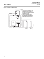
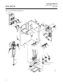
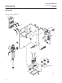
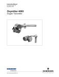
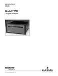
1
Instruction Manual
IM-106-340AC-1, Rev 1.0
April 2005
SPS 4001B
Single Probe Autocalibration Sequencer
http://www.raihome.com
Instruction Manual
IM-106-340AC-1, Rev. 1.0
April 2005
SPS 4001B
Table of Contents
Essential Instructions. . . . . . . . . . . . . . . . . . . . . . . . . . . . . . . . . . . . . . . . i
Preface . . . . . . . . . . . . . . . . . . . . . . . . . . . . . . . . . . . . . . . . . . . . . . . . . . ii
Definitions . . . . . . . . . . . . . . . . . . . . . . . . . . . . . . . . . . . . . . . . . . . . . . . . ii
Symbols . . . . . . . . . . . . . . . . . . . . . . . . . . . . . . . . . . . . . . . . . . . . . . . . . . ii
SECTION 1
Description and
Specifications
Component Checklist. . . . . . . . . . . . . . . . . . . . . . . . . . . . . . . . . . . . . . 1-1
Overview . . . . . . . . . . . . . . . . . . . . . . . . . . . . . . . . . . . . . . . . . . . . . . . 1-1
Specifications. . . . . . . . . . . . . . . . . . . . . . . . . . . . . . . . . . . . . . . . . . . . 1-2
Physical Description . . . . . . . . . . . . . . . . . . . . . . . . . . . . . . . . . . . . . . 1-3
Theory of Operation. . . . . . . . . . . . . . . . . . . . . . . . . . . . . . . . . . . . . . . 1-5
SECTION 2
Installation
Overview . . . . . . . . . . . . . . . . . . . . . . . . . . . . . . . . . . . . . . . . . . . . . . . 2-1
Mechanical Installation . . . . . . . . . . . . . . . . . . . . . . . . . . . . . . . . . . . . 2-1
Gas Connections . . . . . . . . . . . . . . . . . . . . . . . . . . . . . . . . . . . . . . . . . 2-2
Electrical Connections . . . . . . . . . . . . . . . . . . . . . . . . . . . . . . . . . . . . . 2-4
SECTION 3
Operation
Overview . . . . . . . . . . . . . . . . . . . . . . . . . . . . . . . . . . . . . . . . . . . . . . . 3-1
Calibration Requirements . . . . . . . . . . . . . . . . . . . . . . . . . . . . . . . . . . 3-1
Reference Air Flow Setup . . . . . . . . . . . . . . . . . . . . . . . . . . . . . . . . . . 3-3
Calibration Gas Flow Setup . . . . . . . . . . . . . . . . . . . . . . . . . . . . . . . . . 3-3
Automatic Calibration. . . . . . . . . . . . . . . . . . . . . . . . . . . . . . . . . . . . . . 3-3
Semi-automatic Calibration . . . . . . . . . . . . . . . . . . . . . . . . . . . . . . . . . 3-4
SECTION 4
Maintenance and
Service
Overview . . . . . . . . . . . . . . . . . . . . . . . . . . . . . . . . . . . . . . . . . . . . . . . 4-1
Fuse Replacement. . . . . . . . . . . . . . . . . . . . . . . . . . . . . . . . . . . . . . . . 4-1
Remove/Install Chassis . . . . . . . . . . . . . . . . . . . . . . . . . . . . . . . . . . . . 4-3
Circuit Board Replacement . . . . . . . . . . . . . . . . . . . . . . . . . . . . . . . . . 4-5
Solenoid Replacement. . . . . . . . . . . . . . . . . . . . . . . . . . . . . . . . . . . . . 4-5
Pressure Switch Replacement. . . . . . . . . . . . . . . . . . . . . . . . . . . . . . . 4-6
Check Valve Replacement . . . . . . . . . . . . . . . . . . . . . . . . . . . . . . . . . 4-6
Pressure Regulator Maintenance . . . . . . . . . . . . . . . . . . . . . . . . . . . . 4-6
Flow Meter Adjustments . . . . . . . . . . . . . . . . . . . . . . . . . . . . . . . . . . . 4-6
SECTION 5
Troubleshooting
Overview . . . . . . . . . . . . . . . . . . . . . . . . . . . . . . . . . . . . . . . . . . . . . . . 5-1
SPS 4001B Troubleshooting . . . . . . . . . . . . . . . . . . . . . . . . . . . . . . . . 5-1
SECTION 6
Replacement Parts
SPS 4001B . . . . . . . . . . . . . . . . . . . . . . . . . . . . . . . . . . . . . . . . . . . . . 6-2
Calibration Components . . . . . . . . . . . . . . . . . . . . . . . . . . . . . . . . . . . 6-3
APPENDIX A
Safety Data
Safety Instructions . . . . . . . . . . . . . . . . . . . . . . . . . . . . . . . . . . . . . . . . A-2
APPENDIX B
Return of Materials
Returning Material . . . . . . . . . . . . . . . . . . . . . . . . . . . . . . . . . . . . . . . . B-1
TOC-1
Instruction Manual
SPS 4001B
TOC-2
IM-106-340AC-1, Rev. 1.0
April 2005
Instruction Manual
IM-106-340AC-1, Rev. 1.0
April 2005
SPS 4001B
SPS 4001B Single Probe
Autocalibration Sequencer
ESSENTIAL
INSTRUCTIONS
READ THIS PAGE BEFORE PROCEEDING!
Rosemount Analytical designs, manufactures and tests its products to meet
many national and international standards. Because these instruments are
sophisticated technical products, you MUST properly install, use, and
maintain them to ensure they continue to operate within their normal
specifications. The following instructions MUST be adhered to and integrated
into your safety program when installing, using, and maintaining Rosemount
Analytical products. Failure to follow the proper instructions may cause any
one of the following situations to occur: Loss of life; personal injury; property
damage; damage to this instrument; and warranty invalidation.
• Read all instructions prior to installing, operating, and servicing the
product.
• If you do not understand any of the instructions, contact your
Rosemount Analytical representative for clarification.
• Follow all warnings, cautions, and instructions marked on and
supplied with the product.
• Inform and educate your personnel in the proper installation,
operation, and maintenance of the product.
• Install your equipment as specified in the Installation Instructions
of the appropriate Instruction Manual and per applicable local and
national codes. Connect all products to the proper electrical and
pressure sources.
• To ensure proper performance, use qualified personnel to install,
operate, update, program, and maintain the product.
• When replacement parts are required, ensure that qualified people use
replacement parts specified by Rosemount. Unauthorized parts and
procedures can affect the product's performance, place the safe
operation of your process at risk, and VOID YOUR WARRANTY.
Look-alike substitutions may result in fire, electrical hazards, or
improper operation.
• Ensure that all equipment doors are closed and protective covers
are in place, except when maintenance is being performed by
qualified persons, to prevent electrical shock and personal injury.
The information contained in this document is subject to change without
notice.
http://www.raihome.com
Instruction Manual
IM-106-340AC-1, Rev. 1.0
April 2005
SPS 4001B
PREFACE
The purpose of this manual is to provide information concerning the
components, functions, installation and maintenance of the SPS 4001B
Single Probe Autocalibration Sequencer.
Some sections may describe equipment not used in your configuration. The
user should become thoroughly familiar with the operation of this module
before operating it. Read this instruction manual completely.
DEFINITIONS
The following definitions apply to WARNINGS, CAUTIONS, and NOTES
found throughout this publication.
Highlights an operation or maintenance procedure, practice, condition, statement, etc. If not
strictly observed, could result in injury, death, or long-term health hazards of personnel.
Highlights an operation or maintenance procedure, practice, condition, statement, etc. If not
strictly observed, could result in damage to or destruction of equipment, or loss of
effectiveness.
NOTE
Highlights an essential operating procedure, condition, or statement.
SYMBOLS
: EARTH (GROUND) TERMINAL
: PROTECTIVE CONDUCTOR TERMINAL
: RISK OF ELECTRICAL SHOCK
: WARNING: REFER TO INSTRUCTION BULLETIN
NOTE TO USERS
The number in the lower right corner of each illustration in this publication is a
manual illustration number. It is not a part number, and is not related to the
illustration in any technical manner.
ii
Instruction Manual
IM-106-340AC-1, Rev. 1.0
April 2005
Section 1
SPS 4001B
Description and Specifications
Component Checklist . . . . . . . . . . . . . . . . . . . . . . . . . . . . . page 1-1
Overview . . . . . . . . . . . . . . . . . . . . . . . . . . . . . . . . . . . . . . . page 1-1
Specifications . . . . . . . . . . . . . . . . . . . . . . . . . . . . . . . . . . . page 1-2
COMPONENT
CHECKLIST
A typical SPS 4001B Single Probe Autocalibration Sequencer should contain
the items shown in Figure 1-1. Record the part number, serial number, and
order number for the SPS 4001B on the back cover of this manual.
NOTE
The SPS 4001B operates exactly the same with either the Oxymitter 4000
Oxygen Transmitter or the Oxymitter 5000 Oxygen Transmitter with
FOUNDATION fieldbus communications. Any references to the Oxymitter
4000 throughout this instruction manual also apply to the Oxymitter 5000.
Figure 1-1. SPS 4001B Package
1
2
yt
ic
al
1. SPS 4001B
2. Instruction Manual
OVERVIEW
An
al
y
tic
al
37470004
A
n
al
The SPS 4001B provides the capability of performing automatic, timed or on
demand, calibrations of a single Oxymitter 4000 without sending a technician
to the probe site.
The SPS 4001B replaces the SPS 4000, a similar unit with exposed analog
devices mounted to a stainless steel support bracket. The operating
parameters of the SPS 4000 and SPS 4001B are identical. All SPS units
require additional calibration system components. These components,
available from Rosemount Analytical, are listed in Table 1-1.
http://www.processanalytic.com
Instruction Manual
IM-106-340AC-1, Rev. 1.0
April 2005
SPS 4001B
The SPS 4001B is fully enclosed in a NEMA cabinet suited for wall-mounting.
The enclosure provides added protection against corrosive atmospheres and
incidental impact damage.
SPECIFICATIONS
Rosemount Analytical has offered multiprobe autocalibration sequencer
systems for many years. These autocalibration systems are most cost
effective for boilers and other combustion processes that utilize many probes.
Users with only one probe per combustion process can take advantage of
Rosemount Analytical's autocalibration capability with the SPS 4001B.
Specifications
SPS 4001B Assembly
Part Number
Mounting
Materials of Construction:
Enclosure
Manifold
Pneumatic tubing - Low
Pressure
Pneumatic tubing - High
Pressure
Assembly hardware
Humidity range
Ambient temperature range
Enclosure protection
Hazardous area option(1)
Electrical entries
Input power
Power consumption
External electrical noise
Handshake signal to/from
Oxymitter 4000
(self-powered)
Cal initiate input from control
room:
In-Cal Relay Contact(4)(5)
Cal Failed Relay Contact(4)(5)
Cabling distance between SPS
4001B and Oxymitter 4000
Piping distance between
SPS 4001B and
Oxymitter 4000 (2) (3)
Approximate shipping weight
Pollution degree
Overvoltage Category
Certification
6A00175G01
Wall mount
Fiberglass
Aluminum with 1/4 in. NPT ports
Buna N with overbraid
Impolene
Galvanized and stainless steel
5 - 95% relative humidity, non condensing
-40° to 149°F (-40° to 65°C) with optional heater
-25° to 149°F (-5° to 65°C)
NEMA 4 (IP66)
Z-purge (by owner)
1/2 in. NPT (0.875 in. with gland)
90 to 250 VAC ±10%, 50/60 Hz
5VA maximum
EN 61326-1 class A
5V (5mA maximum)
Internally 5V powered
5 to 30 VDC, 100 mA, Form A (SPST)
5 to 30 VDC, 100 mA, Form A (SPST)
Maximum 1000 ft (303 m)
Maximum 300 ft (91 m)
10 lbs (4.5 kg)
2
II
General Purpose
C
US
APPROVED
NOTES
(1) Hazardous area option requires the addition of a Z-purging system by the owner.
(2) Reference air is recommended with 9 ft (2.74 m) and 12 ft (3.66 m) long probes. Reference air is also
recommended when ambient air may not contain the normal 20.95% O2, such as when the probe is
mounted into a positive pressure duct with leaks or where there is a process unit nearby with leaks.
(3) Customer to provide piping from remote SPS 4001B to probe.
(4) External current limiting device must be provided by customer.
(5) If contacts are used to drive relay coils, a reverse blocking (flyback) diode must be installed on the input
to the relay coil. Relay and diode to be provided by customer.
1-2
Instruction Manual
IM-106-340AC-1, Rev. 1.0
April 2005
SPS 4001B
Table 1-1. Calibration
Components
PART NUMBER
DESCRIPTION
Two disposable calibration gas bottles - 0.4% and 8% O2, balance
nitrogen - 550 liters each (1) (2)
1A99119G01
1A99119G02
Two flow regulators for calibration gas bottles
1A99119G03
Bottle rack
NOTES
(1) Calibration gas bottles cannot be shipped via airfreight.
(2) When the bottles are used with "CALIBRATION RECOMMENDED" features, the bottles should provide
2 to 3 years of calibrations in normal service.
PHYSICAL
DESCRIPTION
The main components of the SPS 4001B are illustrated in Figure 1-2.
Manifold
The manifold provides porting to and from the calibration solenoids. The
manifold ports are accessible from outside the enclosure for making piping
connections. The Oxymitter 4000 calibration gases are piped into and
sequenced through the calibration gas solenoids mounted on the manifold.
Figure 1-2. SPS 4001B Components
CALIBRATION GAS
FLOW METER
REFERENCE AIR
FLOW METER
CIRCUIT
BOARD
OU
T
REFERENCE
AIR PRESSURE
REGULATOR
MANIFOLD
CALIBRATION GAS 1
(LOW CAL GAS)
SOLENOID
CALIBRATION GAS 2
(HIGH CAL GAS)
SOLENOID
37740002
PRESSURE
SWITCH
1-3
Instruction Manual
IM-106-340AC-1, Rev. 1.0
April 2005
SPS 4001B
Calibration Gas Solenoids
The solenoids sequence the calibration gases. One solenoid controls
calibration gas 1 (high calibration gas), and the other controls calibration gas
2 (low calibration gas). The solenoids activate and deactivate to allow the
calibration gases to flow between the sequencer and Oxymitter 4000.
Pressure Switch
The pressure switch detects if the pressure of a calibration gas is low, which
can be caused by an empty gas bottle, a disconnected gas line, etc.
Calibration is prohibited when calibration gas pressure is low.
Circuit Board
The circuit board converts the incoming line voltage from AC to DC for use by
the solenoids, terminations, and the programmable logic device. The power
circuit is protected by a 1.6 A, 250 V, fast acting fuse.
The board contains a programmable logic device (PLD) that has the
electronics to energize and deenergize the solenoids based on a signal from
the Oxymitter 4000.
A terminal strip provides convenient access for all signal and power user
connections.
Calibration Gas Flow Meter
The calibration gas flow meter indicates the flow rate of calibration gas flowing
to the Oxymitter 4000.
Reference Air Flow Meter
The reference air flow meter indicates the amount of reference air
continuously flowing to the Oxymitter 4000.
Pressure Regulator
The pressure regulator ensures the instrument air (reference air) flowing to
the Oxymitter 4000 is at a constant pressure [20 psi (138 kPa)]. The regulator
also has a filter to remove particulates in the reference air and a drain valve to
bleed the moisture that collects in the filter bowl.
1-4
Instruction Manual
IM-106-340AC-1, Rev. 1.0
April 2005
THEORY OF
OPERATION
SPS 4001B
The Oxymitter 4000 is one of the few instruments found in industry that permit
the permanent piping of a calibration standard into the probe. Most
instruments measuring pressure, flow, or temperature, require that a
calibration standard be brought to the instrument or that the instrument be
taken to the calibration source in the instrument shop.
The permanent calibration gas connections allow for autocalibrations to occur
without operator intervention. The following paragraphs describe how an
Oxymitter 4000 is autocalibrated when used with the SPS 4001B.
In addition to the calibration methods available via the Oxymitter 4000
keypad, HART communicator, AMS software, or a remote contact, the SPS
4001B works in conjunction with the Oxymitter 4000's CAL RECOMMENDED
feature to perform an autocalibration.
This feature automatically performs an impedance check every hour on the
Oxymitter 4000. If a calibration is recommended and its contact output signal
is set for "handshaking" with the SPS 4001B sequencer, the Oxymitter 4000
sends a signal to the sequencer. The sequencer automatically performs a
calibration upon receiving the signal. Therefore, no human interface is
required for the automatic calibration to take place.
See Figure 1-3. When a calibration is required, the Oxymitter 4000 sends a
signal to the programmable logic device (PLD) on the interface board of the
sequencer. The PLD energizes the calibration gas 1 (high O2) solenoid.
Calibration gas 1 then flows through the sequencer to the Oxymitter 4000.
The Oxymitter 4000 measures the oxygen content of calibration gas 1 and
sends a signal to the sequencer indicating that it received the gas. When the
sequencer receives the signal, the PLD deenergizes the calibration gas 1
solenoid.
Next, the PLD energizes the calibration gas 2 (low O2) solenoid, and
calibration gas 2 then flows through the sequencer to the Oxymitter 4000. The
Oxymitter 4000 measures the oxygen content of calibration gas 2 and sends
a signal to the sequencer indicating that it received the gas. After measuring
the two calibration gases, the Oxymitter 4000 automatically makes an internal
calibration adjustment and sends the signal to the sequencer. When the
sequencer receives the signal, the PLD deenergizes the calibration gas 2
solenoid.
1-5
Instruction Manual
IM-106-340AC-1, Rev. 1.0
April 2005
SPS 4001B
Figure 1-3. SPS 4001B Calibration Setup
OXYMITTER 4000
(BOTTOM VIEW)
OXYMITTER 4000
LOGIC I/O
37740005
INSTRUMENT
AIR IN
(SEE NOTE 2)
REFERENCE AIR (SEE NOTE 2)
CALIBRATION GAS
1. A CHECK VALVE IS REQUIRED AT THE
OXYMITTER 4000 (BETWEEN THE
CALIBRATION GAS FITTING AND THE
GAS LINE) TO PREVENT THE MIGRATION
OF PROCESS GASES DOWN THE
CALIBRATION GAS LINE.
2. CLEAN, DRY INSTRUMENT AIR IS
RECOMMENDED FOR REFERENCE AIR.
NO REFERENCE AIR IS REQUIRED IF
AMBIENT AIR CONDITIONS CONTAIN
20.95% OXYGEN.
CHECK VALVE
(SEE NOTE 1)
SPS
4001B
NOTES:
CALIBRATION
GAS 1
(HIGH O2)
1-6
CALIBRATION
GAS 2
(LOW O2)
Instruction Manual
IM-106-340AC-1, Rev. 1.0
April 2005
Section 2
SPS 4001B
Installation
Overview . . . . . . . . . . . . . . . . . . . . . . . . . . . . . . . . . . . . . . . page 2-1
Mechanical Installation . . . . . . . . . . . . . . . . . . . . . . . . . . . page 2-1
Gas Connections . . . . . . . . . . . . . . . . . . . . . . . . . . . . . . . . page 2-2
Electrical Connections . . . . . . . . . . . . . . . . . . . . . . . . . . . . page 2-4
OVERVIEW
This section describes SPS 4001B installation.
Before starting to install this equipment, read the "Safety instructions for the wiring and
installation of this apparatus" in Section A: Safety Data. Failure to follow the safety
instructions could result in serious injury or death.
Secure equipment cover and ground leads after installation. Failure to secure covers and
ground leads could result in serious injury or death.
MECHANICAL
INSTALLATION
The outline drawing in Figure 2-1 shows mounting centers and clearances of
the SPS 4001B. The unit is designed to mount on a wall, bulkhead, or pipe.
Ensure the unit is installed according to the following specifications.
1. Install the unit no further than 300 ft (91 m) from the Oxymitter 4000 and
no further than 1000 ft (303 m) from the electronics package or any
customer-supplied remote input or relay output in the control room.
2. Locate the unit where the ambient temperature is between -25° and
149°F (-5° and 65°C) or -40° and 149°F (-40° and 65°C) with optional
heater.
http://www.processanalytic.com
Instruction Manual
IM-106-340AC-1, Rev. 1.0
April 2005
SPS 4001B
GAS CONNECTIONS
Use the following procedures to connect the reference air and the calibration
gases.
Reference Air (Figure 2-1)
The Oxymitter 4000 requires a source of reference air that is constantly
20.95% O2. Clean and dry instrument air provides the most stable source of
reference air. If instrument air is unavailable, the reference air port of the
probe can be left open, permitting ambient air to passively diffuse into the
probe.
1. Connect the instrument air supply to the INST AIR IN port of the
manifold.
2. The pressure regulator is factory set at 20 psi (138 kPa). If necessary,
readjust by turning the knob on the top of the regulator until the desired
pressure is obtained.
3. Next, connect the reference air from the REF GAS OUT port of the
manifold to the REF GAS port on the Oxymitter 4000.
Calibration Gas (Figure 2-1)
1. Connect O2 calibration gas 1 (high calibration gas) to the HI GAS IN
port on the manifold. Ensure the calibration gas pressure is set at 20 psi
(138 kPa).
Instrument air is not recommended for the high calibration gas. Do not use 100% nitrogen
as a low gas (zero gas). It is suggested that the low (zero) gas be between 0.4% and 2.0%
O2. Do not use gases with hydrocarbon concentrations of more than 40 parts per million.
Failure to use proper gases will result in erroneous readings.
2. Connect O2 calibration gas 2 (low calibration gas) to the LOW GAS IN
port on the manifold. Ensure the calibration gas pressure is set at 20 psi
(138 kPa).
3. Connect the calibration gas from the CAL GAS OUT manifold fitting to
the check valve connected to the CAL GAS port on the Oxymitter 4000.
2-2
Instruction Manual
IM-106-340AC-1, Rev. 1.0
April 2005
SPS 4001B
Figure 2-1. Installation
REPLACEABLE
MOUNTING FOOT
(4 PLACES)
5-15/16
(151)
11
(279)
Analytical
CONDENSATE
DISCHARGE TUBE
(FROM AIR PRESSURE
REGULATOR/FILTER)
TEST GAS
OUT
REF GAS
OUT
SIGNAL
CABLE IN
INST AIR
IN
MANIFOLD
6-1/2
(165)
3/8 IN. (9,5 MM)
CABLE GRIPS
LOW GAS
IN
HI GAS
IN
NOTE: DIMENSIONS ARE IN INCHES WITH
MILLIMETERS IN PARENTHESES.
37470007
POWER
CABLE IN
2-3
Instruction Manual
SPS 4001B
ELECTRICAL
CONNECTIONS
IM-106-340AC-1, Rev. 1.0
April 2005
All wiring must conform to local and national codes. Use the following
procedure to connect an SPS 4001B to an Oxymitter 4000.
Disconnect and lock out power before connecting the unit to the power supply.
NOTE
Ensure the Oxymitter 4000 is set up to handshake with the sequencer by
configuring the logic I/O to mode 8. Refer to the Oxymitter 4000 Oxygen
Transmitter Instruction Manual for more information.
NOTE
To maintain proper earth grounding, ensure a positive connection exists
between the ground lug and earth.
1. Loosen the SPS 4001B cover screws and open the cover.
2. Route the line voltage cable into the enclosure through the rear cable
grip. Ensure adequate wire length to connect the line voltage leads per
Figure 2-2, then tighten the cable grip nut.
3. Connect the incoming 90 to 250 VAC ±10%, 50/60 Hz line voltage leads
to the terminal strip and ground lug as indicated in Figure 2-2.
4. Route the signal wiring cable through the front cable grip. Ensure
adequate wire length to connect all signal wires per Figure 2-2, then
tighten the cable grip nut. Use shielded twisted pair wiring. Terminate
the shield at the SPS 4001B.
5. Connect the 5V (5 mA maximum) logic I/O leads from the Oxymitter
4000 to the terminal strip as indicated in Figure 2-2. Use shielded
twisted pair wiring. Terminate the shield at the Oxymitter 4000.
6. To set up the SPS 4001B to initiate a calibration from a remote location,
connect the 5 VDC input leads to the terminal strip as shown in
Figure 2-2.
7. Relay output connections are available on the unit to signal when the
Oxymitter 4000 is in calibration or when calibration failed. Relay outputs
can be connected to either indicator lights or a computer interface. The
relay contacts are capable of handling a 5 to 30 VDC maximum power
source. The cabling requirement is 1000 ft (303 m) maximum. Connect
the relay output wires to the terminal strip as shown in Figure 2-2. Use
shielded twisted pair wiring. Terminate the shield at the SPS 4001B.
8. Once all connections are made, close the enclosure cover and tighten
the cover screws.
2-4
Instruction Manual
IM-106-340AC-1, Rev. 1.0
April 2005
SPS 4001B
Figure 2-2. Electrical
Connections
L1
90 - 250 VAC,
50/60 HZ LINE
VOLTAGE INPUT
N
GROUND
NC
OPTIONAL
5 VDC (SELF-POWERED)
TO REMOTE MOMENTARY
CLOSURE CONTACT
INPUT CONNECTION
5 VDC (5 mA MAXIMUM)
LOGIC I/O
CONNECTION TO
OXYMITTER 4000
CAL INIT
HANDSHAKE
CAL FAIL
OPTIONAL
5 - 30 VDC TO
RELAY OUTPUT
CONNECTIONS
IN CAL
GROUND
LUG
GND
37740003
EARTH GROUND
CABLE SHIELDS
}
}
2-5
Instruction Manual
SPS 4001B
2-6
IM-106-340AC-1, Rev. 1.0
April 2005
Instruction Manual
IM-106-340AC-1, Rev. 1.0
April 2005
Section 3
SPS 4001B
Operation
Overview . . . . . . . . . . . . . . . . . . . . . . . . . . . . . . . . . . . . . . . page 3-1
Calibration Requirements . . . . . . . . . . . . . . . . . . . . . . . . . page 3-1
Reference Air Flow Setup . . . . . . . . . . . . . . . . . . . . . . . . . page 3-3
Calibration Gas Flow Setup . . . . . . . . . . . . . . . . . . . . . . . . page 3-3
Automatic Calibration . . . . . . . . . . . . . . . . . . . . . . . . . . . . page 3-3
Semi-automatic Calibration . . . . . . . . . . . . . . . . . . . . . . . . page 3-4
OVERVIEW
This section specifies the requirements to set up an Oxymitter 4000
calibration and how to verify the calibration gas flow setup. It also explains the
differences between automatic and semi-automatic calibrations and how to
initiate them.
CALIBRATION
REQUIREMENTS
Calibration Gas Tanks
Two tanks of precision calibration gas mixtures are required. Recommended
calibration gases are nominally 0.4% and 8.0% oxygen in nitrogen.
Do not use 100% nitrogen as a low gas (zero gas). It is suggested that gas for the low (zero)
be between 0.4% and 2.0% O2. Do not use gases with hydrocarbon concentrations of more
than 40 parts per million. Failure to use proper gases will result in erroneous readings.
http://www.processanalytic.com
Instruction Manual
IM-106-340AC-1, Rev. 1.0
April 2005
SPS 4001B
In addition to the optional disposable gas bottles available from Rosemount
Analytical, two additional sources of calibrated gas mixtures are:
LIQUID CARBONIC GAS CORP.
SPECIALTY GAS LABORATORIES
700 South Alameda Street
Los Angeles, California 90058
213/585-2154
767 Industrial Road
San Carlos, California 94070
415/592-7303
9950 Chemical Road
Pasadena, Texas 77507
713/474-4141
12054 S.W. Doty Avenue
Chicago, Illinois 60628
312/568-8840
603 Bergen Street
Harrison, New Jersey 07029
201/485-1995
255 Brimley Road
Scarborough, Ontario, Canada
416/266-3161
SCOTT ENVIRONMENTAL
TECHNOLOGY, INC.
SCOTT SPECIALTY GASES
2600 Cajon Blvd.
San Bernardino, California 92411
714/887-2571
TWX: 910-390-1159
1290 Combermere Street
Troy, Michigan 48084
314/589-2950
Route 611
Plumsteadville, Pennsylvania 18949
215/766-8861
TWX: 510-665-9344
2616 South Loop West
Suite 100
Houston, Texas 77054
713/669-0469
Check Valve
A check valve is required at the Oxymitter 4000 (between the calibration fitting
and the gas line) to prevent the migration of process gases down the
calibration gas line between calibrations.
A typical calibration setup for the Oxymitter 4000 is shown in Figure 1-3.
3-2
Instruction Manual
IM-106-340AC-1, Rev. 1.0
April 2005
SPS 4001B
REFERENCE AIR FLOW
SETUP
If instrument air is to be used as the reference gas, set the reference air
pressure regulator to 20 psig (138 kPa gage) and set the reference air flow
meter to 2 scfh. Refer to the Reference Air Package in the Oxymitter 4000
Instruction Manual for more information.
CALIBRATION GAS
FLOW SETUP
After installing the SPS 4001B as described in Section 2, Installation,
calibrate the Oxymitter 4000 to verify SPS 4001B operation and the
communication link between the sequencer and Oxymitter 4000.
1. Verify that both calibration gases are connected to the SPS 4001B. Also
verify that the pressure regulators on both calibration gas bottles are set
to 20 psi (138 kPa).
2. Initiate a semi-automatic calibration using one of the methods in
"Semi-automatic Calibration".
NOTE
Set the calibration gas flow meter only upon initial installation and after
changing the diffusion element in the Oxymitter 4000. Refer to the flow meter
adjustments in Section 4, Maintenance and Service for more information.
3. As the Oxymitter 4000 and SPS 4001B apply the first calibration gas,
set the calibration gas flow meter to 5 scfh. When the second calibration
gas is applied, verify that the flow meter reads 5 scfh. If not, adjust the
pressure regulator on the second calibration gas bottle so the 5 scfh
flow is provided.
AUTOMATIC
CALIBRATION
Automatic calibrations require no operator action and can be performed
through the Oxymitter 4000 CAL RECOMMENDED feature or through
scheduled time intervals that can be programmed through the HART/AMS for
the Oxymitter 4000. In addition, the calibration gases must be permanently
piped to the Oxymitter 4000.
CAL RECOMMENDED
If the Oxymitter 4000 is configured for handshake mode with the SPS 4001B,
the Oxymitter 4000 can initiate a calibration by sending a signal to the
sequencer when the CAL RECOMMENDED LED activates. To enable
handshake mode, the Oxymitter 4000 logic I/O must be set for mode 8 or
mode 9 (handshake).
The handshake mode is configured at the factory or can be accessed through
HART/AMS. Refer to the logic I/O information in the HART/AMS section of the
Oxymitter 4000 Instruction Manual for more information.
Timed Interval
An automatic calibration can also be programmed to occur at a specific time
interval, in hours, using the HART communicator or AMS software. Refer to
the HART/AMS section of the Oxymitter 4000 Oxygen Transmitter Instruction
Manual for this procedure.
3-3
Instruction Manual
IM-106-340AC-1, Rev. 1.0
April 2005
SPS 4001B
SEMI-AUTOMATIC
CALIBRATION
Semi-automatic calibrations are operator initiated and can be performed using
the Oxymitter 4000 keypad, HART handheld communicator/AMS software, or
a remote contact. In addition, the calibration gases must be permanently
piped to the Oxymitter 4000.
Oxymitter 4000 Keypad
A semi-automatic calibration can be initiated by pressing the CAL button on
the Oxymitter 4000 keypad. For more information, refer to the Oxymitter 4000
Oxygen Transmitter Instruction Manual.
HART Handheld Communicator/AMS Software
A semi-automatic calibration can be initiated by connecting the HART
handheld communicator, or AMS software, to the Oxymitter 4000 4-20 mA
signal line and using the HART communicator keypad or computer keyboard
to access the applicable calibration menu. Refer to the Oxymitter 4000
Oxygen Transmitter Instruction Manual or HART documentation for more
information.
Remote Contact
A semi-automatic calibration can be initiated using a remote contact such as a
customer's control system. The remote contact processes the calibration
command on a PC and sends the signal to the Oxymitter 4000. For more
information on remote-site calibrations, refer to the documentation for the
system in use.
3-4
Instruction Manual
IM-106-340AC-1, Rev. 1.0
April 2005
Section 4
SPS 4001B
Maintenance and Service
Overview . . . . . . . . . . . . . . . . . . . . . . . . . . . . . . . . . . . . . . . page 4-1
Fuse Replacement . . . . . . . . . . . . . . . . . . . . . . . . . . . . . . . page 4-1
Remove/Install Chassis . . . . . . . . . . . . . . . . . . . . . . . . . . . page 4-3
Circuit Board Replacement . . . . . . . . . . . . . . . . . . . . . . . . page 4-5
Solenoid Replacement . . . . . . . . . . . . . . . . . . . . . . . . . . . . page 4-5
Pressure Switch Replacement . . . . . . . . . . . . . . . . . . . . . page 4-6
Check Valve Replacement . . . . . . . . . . . . . . . . . . . . . . . . . page 4-6
Pressure Regulator Maintenance . . . . . . . . . . . . . . . . . . . page 4-6
Flow Meter Adjustments . . . . . . . . . . . . . . . . . . . . . . . . . . page 4-6
OVERVIEW
This section describes service and routine maintenance of the SPS 4001B.
Replacement parts are available from Rosemount Analytical. Refer to
Section 6, Replacement Parts for part numbers and ordering information.
Secure equipment cover and ground leads after equipment service. Failure to secure
covers and ground leads could result in serious injury or death.
FUSE REPLACEMENT
The SPS 4001B has a fuse on the circuit board. Refer to Section 6,
Replacement Parts for replacement fuse specifications. Perform the following
procedure to check or replace the fuse.
Disconnect and lock out power before working on any electrical components.
1. Turn off power to the system and open the enclosure cover.
2. Push in and turn the fuseholder cap 1/4 turn counterclockwise. Remove
the fuse.
3. After checking or replacing the fuse, install fuseholder cap. Push in and
turn the cap 1/4 turn clockwise.
4. Install the enclosure cover and secure the cover screws.
http://www.raihome.com
Instruction Manual
IM-106-340AC-1, Rev. 1.0
April 2005
SPS 4001B
Figure 4-1. SPS 4001B, Exploded View
25
26
1
2
19
4
3
19
5
27
18
8
24
OU
T
7
27
6
10
23
7
11
6
7
12
19
15
16
14
13
22
9
21
Lo Cal Gas
20
Hi Cal Gas
4-2
17
18
37740001
19
Instruction Manual
IM-106-340AC-1, Rev. 1.0
April 2005
1.
2.
3.
4.
5.
6.
7.
Screw
Fuse
Nylon Washer
Standoff
Circuit Board
Hex Nut
External Lock Washer
REMOVE/INSTALL
CHASSIS
SPS 4001B
8.
9.
10.
11.
12.
13.
14.
Screw
Adapter Fitting
Impolene Tubing
Tubing
Straight Fitting
Manifold
High Cal. Gas Solenoid
15.
16.
17.
18.
19.
20.
21.
Low Cal. Gas Solenoid
Pressure Switch
Manifold Gasket
Screw
Elbow Fitting
Grommet
Teflon Tubing
22. Reference Air Pressure
Regulator
23. Elbow Adapter
24. Chassis
25. Reference Air Flow Meter
26. Cal. Gas Flow Meter
27. Ground Wire
Perform the following procedures to remove the SPS 4001B chassis from the
enclosure for service, and to reinstall the chassis after the service tasks are
completed.
Removal
1. Loosen the SPS 4001B cover screws and open the cover.
2. Shut off the calibration gas and reference air to the SPS 4001B.
Disconnect all pneumatic lines at the SPS 4001B manifold.
3. Refer to Figure 2-2. Disconnect all wires from the chassis terminals and
remove the power cable ground lead from the ground lug.
4. Refer to Figure 4-1. Remove two screws (18) that secure chassis (24) to
manifold (13).
5. Loosen captive screw (1) that secures chassis (24) to enclosure.
6. Place one hand on the front of chassis (24) and tip the enclosure
up-side-down. Remove chassis from enclosure and place chassis and
enclosure on work surface.
Installation
1. Push up on the base of the fitting installed at the bottom of reference air
pressure regulator (22, Figure 4-1). Pull teflon tubing (21) from the
fitting.
2. Stand chassis (24) and enclosure upright and carefully place the
chassis in the enclosure.
3. Tighten captive screw (1).
4. Install and tighten two screws (18) to secure the base of the chassis.
5. Insert teflon tubing (21) through grommet (20) in bottom of enclosure.
Seat the tubing in mating adapter fitting at the bottom of reference air
pressure regulator (22).
6. Refer to Figure 4-2. Connect all signal and power wiring to the chassis
terminals and connect the power cable ground lead to the ground lug.
7. Connect all pneumatic lines at the SPS 4001B manifold. Turn on the
calibration gas and reference air supplies to the SPS 4001B.
8. Close the enclosure cover and secure the cover screws.
4-3
Instruction Manual
IM-106-340AC-1, Rev. 1.0
April 2005
SPS 4001B
Figure 4-2. Terminal
Connections
L1
90 - 250 VAC,
50/60 HZ LINE
VOLTAGE INPUT
N
GROUND
NC
OPTIONAL
5 VDC (SELF-POWERED)
TO REMOTE MOMENTARY
CLOSURE CONTACT
INPUT CONNECTION
5 VDC (5 mA MAXIMUM)
LOGIC I/O
CONNECTION TO
OXYMITTER 4000
CAL INIT
HANDSHAKE
CAL FAIL
OPTIONAL
5 - 30 VDC TO
RELAY OUTPUT
CONNECTIONS
IN CAL
GROUND
LUG
GND
37740003
EARTH GROUND
CABLE SHIELDS
}
}
4-4
Instruction Manual
IM-106-340AC-1, Rev. 1.0
April 2005
CIRCUIT BOARD
REPLACEMENT
SPS 4001B
Perform the following procedure to replace circuit board (5, Figure 4-1).
Disconnect and lock out power before working on any electrical components.
1. Remove the SPS 4001B chassis from the enclosure according to the
instructions in "Remove/Install Chassis".
2. Refer to Figure 4-2. Disconnect wiring from the circuit board.
3. Disconnect the solenoid and pressure switch connectors.
4. Refer to Figure 4-1. Remove circuit board (5) from chassis (24).
5. Connect mating wires to solenoid (14 or 15) and pressure switch (16).
Lo Gas solenoid connects to J6, Hi Gas solenoid to J5, and pressure
switch to J3.
6. Install the replacement circuit board (5) on chassis (24).
7. Reinstall field wiring to circuit board.
8. Install the SPS 4001B chassis in the enclosure according to the
instructions in "Remove/Install Chassis".
SOLENOID
REPLACEMENT
Use this procedure to replace the calibration gas 1 (Hi Gas) solenoid (14,
Figure 4-1) or calibration gas 2 (Low Gas) solenoid (15).
Disconnect and lock out power before working on any electrical components.
1. Remove the SPS 4001B chassis from the enclosure according to the
instructions in "Remove/Install Chassis".
2. Unplug solenoid (14 or 15) lead wire.
3. Remove the top nut of solenoid (14 or 15) securing the coil assembly
and washer to the base. Remove the coil assembly, including the leads,
and washer. Use a 13/16 in. wrench to loosen and remove the solenoid
base.
When installing a solenoid, do not overtighten. Damage to the solenoid may occur.
4. Install the new solenoid base. Be careful not to overtighten. Install the
new washer and coil assembly and secure with the top nut.
5. Connect the solenoid lead wire to solenoid (14 or 15).
6. Install the SPS 4001B chassis in the enclosure according to the
instructions in "Remove/Install Chassis".
4-5
Instruction Manual
IM-106-340AC-1, Rev. 1.0
April 2005
SPS 4001B
PRESSURE SWITCH
REPLACEMENT
Use the following procedure to replace pressure switch (16, Figure 4-1).
1. Remove the SPS 4001B chassis from the enclosure according to the
instructions in "Remove/Install Chassis".
2. Remove lead wire terminals from pressure switch (16).
3. Use a 1-1/16 in. 6-point socket to loosen and remove switch (16).
When installing the pressure switch, do not overtighten. Damage to the solenoid may occur.
4. Install new pressure switch (16). Be careful not to overtighten. Connect
the leads to the pressure switch terminals. Polarity does not matter.
5. Install the SPS 4001B chassis in the enclosure according to the
instructions "Remove/Install Chassis".
CHECK VALVE
REPLACEMENT
The check valve (Figure 1-3) may stick or become plugged over time.
Replace when necessary. If condensation deposits are noted upon removal,
consider insulating the check valve.
PRESSURE
REGULATOR
MAINTENANCE
The reference air pressure regulator (22, Figure 4-1) is factory set to 20 psi
(138 kPa). If necessary, use the knob on top of the pressure regulator to
readjust the pressure setting. Refer to "Remove/Install Chassis" to access the
pressure regulator for adjustment.
FLOW METER
ADJUSTMENTS
Calibration Gas Flow Meter
Calibration gas flow meter (26, Figure 4-1) regulates the calibration gas flow.
The flow meter requires readjustment only after installing a new diffusion
element on the Oxymitter 4000 probe. Adjusting the flow meter at any other
time can pressurize the cell and bias the calibration.
In applications with a heavy dust loading, the O2 probe diffusion element may
become plugged over time, causing a slower speed of response. The best
way to detect a plugged diffusion element is to note the time it takes the
Oxymitter 4000 to return to the normal process reading after the last
calibration gas is removed and the calibration gas line is blocked off. A
plugged element also can be indicated by a slightly lower reading on the flow
meter.
Change the diffusion element when the calibration gas flow meter reads
slightly lower during calibration or when the response time to the process flue
gases becomes very slow. Each time the diffusion element is changed, reset
the calibration gas flow meter and calibrate the Oxymitter 4000. For more
information on changing the diffusion element, refer to the instruction manual
for the Oxymitter 4000 in use.
Reference Air Flow Meter
Reference air flow meter (25) regulates the reference air. Adjust the flow with
the knob on the bottom of the reference air flow meter when necessary.
4-6
Instruction Manual
IM-106-340AC-1, Rev. 1.0
April 2005
Section 5
SPS 4001B
Troubleshooting
Overview . . . . . . . . . . . . . . . . . . . . . . . . . . . . . . . . . . . . . . . page 5-1
SPS 4001B Troubleshooting . . . . . . . . . . . . . . . . . . . . . . . page 5-1
OVERVIEW
This section describes the SPS 4001B troubleshooting procedures. Additional
troubleshooting information can be found in the Oxymitter 4000 Oxygen
Transmitter Instruction Manual.
Secure equipment cover and ground leads after troubleshooting. Failure to secure covers
and ground leads could result in serious injury or death.
SPS 4001B
TROUBLESHOOTING
Use the CAL FAIL and IN CAL relay outputs to identify possible SPS faults.
CAL FAIL
If a calibration was not successfully completed, the SPS 4001B sends a CAL
FAIL contact indication to the control room. To determine if the SPS 4001B
caused the failed calibration, go to the Oxymitter 4000 site to view the keypad.
Or, access the HART/AMS menus. For more information on HART/AMS, refer
to the HART/AMS section in the Oxymitter 4000 Oxygen Transmitter
Instruction Manual.
If no alarms are indicated on the keypad, LOI, or in the HART/AMS STATUS
submenu, the calibration did not fail because of an Oxymitter 4000 fault.
Therefore, a calibration gas flow problem occurred. Refer to Table 5-1 or
Figure 5-1 to troubleshoot the SPS 4001B.
If the LAST CAL FAILED alarm is indicated on the keypad, LOI, or in the
HART/AMS STATUS submenu, the failure is due to either a bad Oxymitter
4000 cell or a calibration gas flow problem.
http://www.raihome.com
Instruction Manual
IM-106-340AC-1, Rev. 1.0
April 2005
SPS 4001B
1. Verify your calibration setup per "Gas Connections" in Section 2,
Installation; Section 3, Operation; and "Flow Meter Adjustments" in
Section 4, Maintenance and Service.
2. Perform another calibration and monitor the process. If the calibration
fails before both calibration gases finish sequencing, a gas flow problem
exists. Refer to Table 5-1 or Figure 5-1 to troubleshoot the SPS 4001B.
If the calibration setup is correct and the Oxymitter 4000 indicates an
invalid slope fault (fault 12) before the gases are purged and a last
calibration failed fault (fault 14) after the gases are purged, replace the
Oxymitter 4000 cell per the Oxymitter 4000 Oxygen Transmitter
Instruction Manual.
Relay Failure
If a semi-automatic or manual calibration is being performed but no 5 - 30
VDC relay output contact (IN CAL or CAL FAIL) is being received by the
control room, the circuit board relays are malfunctioning. Replace the circuit
board per "Circuit Board Replacement" in Section 4, Maintenance and
Service.
NOTE
If the unit is performing frequent auto-calibrations, investigate at the Oxymitter
4000 site or using HART/AMS. This condition may indicate an aging cell in the
Oxymitter 4000.
5-2
Instruction Manual
IM-106-340AC-1, Rev. 1.0
April 2005
SPS 4001B
Table 5-1. SPS 4001B Fault Finding
No calibration gas flow
Probable Cause
Recommended Corrective Action
Improper wire connections, loose
connections, or damaged wiring
Properly connect wiring or secure loose wiring connections; replace damaged wiring if
necessary.
Oxymitter 4000 logic I/O not set for calibration
handshaking with SPS 4001B
Clogged calibration gas line between tank and
manifold
Flow meter knob not turned counterclockwise
to allow flow
Clogged calibration gas line between manifold
and calibration gas flow meter
Blown fuse
Set logic I/O to mode 8 or 9 via HART/AMS.
Circuit board not sending signals
Replace clogged calibration gas line.
Turn calibration gas flow meter knob counter-clockwise to allow calibration gas to flow.
Replace clogged calibration gas line.
Replace fuse per "Fuse Replacement", Section 4, Maintenance and Service
Replace circuit board per "Circuit Board Replacement", Section 4, Maintenance and Service.
Clogged check valve
Replace check valve per "Check Valve Replacement", Section 4, Maintenance and Service.
Clogged calibration gas line between
calibration gas flow meter and check valve
Clogged calibration gas flow meter
Replace calibration gas line.
Solenoid failure
Replace solenoid per "Solenoid Replacement", Section 4, Maintenance and Service.
Pressure switch failure
Replace pressure switch per "Pressure Switch Replacement", Section 4, Maintenance and
Service.
Replace calibration gas flow meter.
5-3
Instruction Manual
IM-106-340AC-1, Rev. 1.0
April 2005
SPS 4001B
Figure 5-1. SPS 4001B Troubleshooting Flowchart (Sheet 1 of 2)
SYMPTOM — NO CALIBRATION GAS FLOW
CHECK ALL WIRING BETWEEN
OXYMITTER 4000 AND SPS 4001B
IS
WIRING
PROPERLY
CONNECTED
AND
SECURE?
NO
PROPERLY CONNECT WIRING
OR SECURE LOOSE WIRING
CONNECTIONS; REPLACE
DAMAGED WIRING.
CHECK LOGIC I/O SETTING VIA
HART/AMS.
C14
H3
J7
TP31
R24
U11
IS
LOGIC I/O
SET
PROPERLY?
J3
J6
J5
YES
TP32
R26
R25
D8
R13
C16
R16
Q1
D10
Q2
K1
H4
K2
TP29
TP30
TP22
TP26
TP25
TP23
TP28
TP20
TP21
TP17
R23
TP27
C23
U9
U5
R17
C18
R20
R22
TP12
TP8
U3
C13
TP4
U6
U7
D11
TP1
J6
D12
L2
R15
Q4
R21
D13
C17
U4
C15
TP2
J3
TP2
D9
D14
TP3
R1
R11
C1
REPLACE CLOGGED CAL GAS
LINE BETWEEN CAL GAS
CYLINDER AND MANIFOLD.
L3
R14
Q5
Q3
J5
L4
R27
TP10
D1
IS THERE
FLOW?
TP5
R19
TP14 TP11 TP7
TP1
NO
TP18
C20
U8
TP15 TP13 TP9 TP6 C19
DISCONNECT CAL GAS INPUT
LINES AT MANIFOLD.
TP16
L5
R28
U10
C21
YES
TP19
TP24
C22
R18
SET LOGIC I/O VIA HART/AMS.
R12
NO
D3
D7
H5
R2
C9
C2
R10
J8
R8
TP3
R7
U1
YES
ENSURE CAL GAS FLOW METER
KNOB IS TURNED COUNTERCLOCKWISE TO ALLOW FLOW.
YES
REV
D2
C11
C10
D5
R9
D6
J9
C6
MOV3
U2
C3
MOV1
R5
REPLACE CLOGGED CAL GAS
LINE BETWEEN MANIFOLD
AND CAL GAS FLOW METER.
C12
C7
R3
NO
Emerson Process Management / PAD
DOES
CAL GAS
FLOW METER
REGISTER
FLOW?
6A00150G
C8
T1
C5
CHECK FUSE F1 ON CIRCUIT
BOARD.
C4
L1
MOV2
D4
XF1
R4
YES
H2
H1
REPLACE FUSE.
R6
F1
NO
CONTINUED
ON SHEET
2 OF 2
5-4
CIRCUIT BOARD
37740006
IS
FUSE
BLOWN?
Instruction Manual
IM-106-340AC-1, Rev. 1.0
April 2005
SPS 4001B
Figure 5-1. SPS 4001B Troubleshooting Flowchart (Sheet 2 of 2)
SYMPTOM — NO CALIBRATION GAS FLOW (CONTINUED)
CONTINUED
FROM SHEET
1 OF 2
NOTE 1: +5 VDC IS ON TP2; TP3 IS RETURN.
+24 VDC IS ON TP1; TP3 IS RETURN.
CHECK +5 VDC AND +24 VDC.
SEE NOTE 1.
NOTE 2: UNPLUG J5. CONNECT SOLENOID PINS 1 AND 3
TO +24 VDC ON TP1. TP3 IS RETURN.
+5 VDC
AND +24 VDC
±10%?
NO
CIRCUIT BOARD IS
FAULTY. REPLACE
CIRCUIT BOARD.
ADDITIONAL INFORMATION
YES
IF FLOW STARTS THEN STOPS AFTER SEVERAL
SECONDS, THE PRESSURE SWITCH MAY BE BAD.
TO TEST PRESSURE SWITCH, UNPLUG FROM J3
AND INSTALL JUMPER ACROSS J3 TERMINALS.
THEN, RESTART CALIBRATION. IF THIS CORRECTS
THE PROBLEM, THE PRESSURE SWITCH IS BAD;
REPLACE IT.
CHECK SOLENOID 1 AND
SOLENOID 2. (SEE NOTE 2 FOR
INSTRUCTIONS).
SOLENOID
1 AND 2
OK?
REPEAT FOR SOLENOID 2 CONNECTED TO J6.
YES
CIRCUIT BOARD IS
FAULTY. REPLACE
CIRCUIT BOARD.
37740009
NO
REPLACE THE SOLENOID
WITH NO FLOW.
5-5
Instruction Manual
SPS 4001B
5-6
IM-106-340AC-1, Rev. 1.0
April 2005
Instruction Manual
IM-106-340AC-1, Rev. 1.0
April 2005
Section 6
SPS 4001B
Replacement Parts
SPS 4001B . . . . . . . . . . . . . . . . . . . . . . . . . . . . . . . . . . . . . . . . . . . . page 6-2
Calibration Components . . . . . . . . . . . . . . . . . . . . . . . . . . . . . . . . page 6-3
http://www.processanalytic.com
Instruction Manual
IM-106-340AC-1, Rev. 1.0
April 2005
SPS 4001B
SPS 4001B
Figure 6-1. Replacement Parts
2
1
3
4
14
3
OU
5
6
T
7
8
3
9
10
9
13
Lo Cal Gas
Hi Cal Gas
12
11
37740007
3
6-2
Instruction Manual
IM-106-340AC-1, Rev. 1.0
April 2005
Index No.
Part Number
1
2
3
4
5
6
7
8
9
10
11
12
13
14
771B635H02
771B635H01
1A98808H03
1A97913H22
6A00150G01
6292A80H01
1A97902H01
1A98808H02
1A97905H01
7305A67H01
6P00151H01
6P00150H01
1A99094H02
1A99785H01
6292A97H03
1A99763H01
SPS 4001B
Description
Flow Meter Assembly, Reference Air
Flow Meter Assembly, Calibration Gas
Fitting, 90 Degree, Nylon, 1/8 NPT
Fuse, 1.6A, 260V, 5 x 20 mm, Fast Acting
Circuit Board
Hose, High Pressure, Impolene
Hose, Low Pressure, Buna N with Overbraid
Fitting, Straight, Nylon, 1/8 NPT
Solenoid Valve
Pressure Switch
Manifold Gasket
Manifold
Reference Air Pressure Regulator
Standoff, Nylon
Check Valve (not shown, see Figure 1-3)
Mounting Foot, Enclosure (not shown, see Figure 2-1)
CALIBRATION
COMPONENTS
Fig. No.
Part Number
1-3
1A99119G01
1-3
1-3
1A99119G02
1A99119G03
Description
Calibration Gas Bottles - 0.4% and 8% O2, balance
nitrogen - 550 liters each*
Two flow regulators (for calibration gas bottles)
Bottle Rack
* Calibration gas bottles cannot be shipped via airfreight.
6-3
Instruction Manual
SPS 4001B
6-4
IM-106-340AC-1, Rev. 1.0
April 2005
Instruction Manual
IM-106-340AC-1, Rev. 1.0
April 2005
Appendix A
SPS 4001B
Safety Data
Safety Instructions . . . . . . . . . . . . . . . . . . . . . . . . . . . . . . . page A-2
http://www.raihome.com
Instruction Manual
IM-106-340AC-1, Rev. 1.0
April 2005
SPS 4001B
SAFETY INSTRUCTIONS
IMPORTANT
SAFETY INSTRUCTIONS FOR THE WIRING
AND INSTALLATION OF THIS APPARATUS
The following safety instructions apply specifically to all EU member
states. They should be strictly adhered to in order to assure compliance
with the Low Voltage Directive. Non-EU states should also comply with
the following unless superseded by local or National Standards.
1. Adequate earth connections should be made to all earthing points,
internal and external, where provided.
2. After installation or troubleshooting, all safety covers and safety grounds
must be replaced. The integrity of all earth terminals must be
maintained at all times.
3. Mains supply cords should comply with the requirements of IEC227 or
IEC245.
4. All wiring shall be suitable for use in an ambient temperature of greater
than 75°C.
5. All cable glands used should be of such internal dimensions as to
provide adequate cable anchorage.
6. To ensure safe operation of this equipment, connection to the mains
supply should only be made through a circuit breaker which will
disconnect all circuits carrying conductors during a fault situation. The
circuit breaker may also include a mechanically operated isolating
switch. If not, then another means of disconnecting the equipment from
the supply must be provided and clearly marked as such. Circuit
breakers or switches must comply with a recognized standard such as
IEC947. All wiring must conform with any local standards.
7. Where equipment or covers are marked with the symbol
to the right, hazardous voltages are likely to be present
beneath. These covers should only be removed when
power is removed from the equipment - and then only
by trained service personnel.
8. Where equipment or covers are marked with the symbol
to the right, there is a danger from hot surfaces beneath.
These covers should only be removed by trained
service personnel when power is removed from the
equipment. Certain surfaces may remain hot to the
touch.
9. Where equipment or covers are marked with the symbol
to the right, refer to the Operator Manual for instructions.
10. All graphical symbols used in this product are from one
or more of the following standards: EN61010-1, IEC417,
and ISO3864.
A-2
Instruction Manual
IM-106-340AC-1, Rev. 1.0
April 2005
SPS 4001B
BELANGRIJK
Veiligheidsvoorschriften voor de aansluiting en installatie van dit
toestel.
De hierna volgende veiligheidsvoorschriften zijn vooral bedoeld voor de
EU lidstaten. Hier moet aan gehouden worden om de onderworpenheid
aan de Laag Spannings Richtlijn (Low Voltage Directive) te verzekeren.
Niet EU staten zouden deze richtlijnen moeten volgen tenzij zij reeds
achterhaald zouden zijn door plaatselijke of nationale voorschriften.
1. Degelijke aardingsaansluitingen moeten gemaakt worden naar alle
voorziene aardpunten, intern en extern.
2. Na installatie of controle moeten alle veiligheidsdeksels en -aardingen
terug geplaatst worden. Ten alle tijde moet de betrouwbaarheid van de
aarding behouden blijven.
3. Voedingskabels moeten onderworpen zijn aan de IEC227 of de IEC245
voorschriften.
4. Alle bekabeling moet geschikt zijn voor het gebruik in
omgevingstemperaturen, hoger dan 75°C.
5. Alle wartels moeten zo gedimensioneerd zijn dat een degelijke kabel
bevestiging verzekerd is.
6. Om de veilige werking van dit toestel te verzekeren, moet de voeding
door een stroomonderbreker gevoerd worden (min 10A) welke alle
draden van de voeding moet onderbreken. De stroomonderbreker mag
een mechanische schakelaar bevatten. Zoniet moet een andere
mogelijkheid bestaan om de voedingsspanning van het toestel te halen
en ook duidelijk zo zijn aangegeven. Stroomonderbrekers of
schakelaars moeten onderworpen zijn aan een erkende standaard
zoals IEC947.
7. Waar toestellen of deksels aangegeven staan met het
symbool is er meestal hoogspanning aanwezig. Deze
deksels mogen enkel verwijderd worden nadat de
voedingsspanning werd afgelegd en enkel door getraind
onderhoudspersoneel.
8. Waar toestellen of deksels aangegeven staan met het
symbool is er gevaar voor hete oppervlakken. Deze
deksels mogen enkel verwijderd worden door getraind
onderhoudspersoneel nadat de voedingsspanning
verwijderd werd. Sommige oppper-vlakken kunnen 45
minuten later nog steeds heet aanvoelen.
9. Waar toestellen of deksels aangegeven staan met het
symbool gelieve het handboek te raadplegen.
10. Alle grafische symbolen gebruikt in dit produkt, zijn
afkomstig uit een of meer van devolgende standaards:
EN61010-1, IEC417 en ISO3864.
A-3
Instruction Manual
IM-106-340AC-1, Rev. 1.0
April 2005
SPS 4001B
VIGTIGT
Sikkerhedsinstruktion for tilslutning og installering af dette udstyr.
Følgende sikkerhedsinstruktioner gælder specifikt i alle
EU-medlemslande. Instruktionerne skal nøje følges for overholdelse af
Lavsspændingsdirektivet og bør også følges i ikke EU-lande medmindre
andet er specificeret af lokale eller nationale standarder.
1. Passende jordforbindelser skal tilsluttes alle jordklemmer, interne og
eksterne, hvor disse forefindes.
2. Efter installation eller fejlfinding skal alle sikkerhedsdæksler og
jordforbindelser reetableres.
3. Forsyningskabler skal opfylde krav specificeret i IEC227 eller IEC245.
4. Alle ledningstilslutninger skal være konstrueret til omgivelsestemperatur
højere end 75°C.
5. Alle benyttede kabelforskruninger skal have en intern dimension, så
passende kabelaflastning kan etableres.
6. For opnåelse af sikker drift og betjening skal der skabes beskyttelse
mod indirekte berøring gennem afbryder (min. 10A), som vil afbryde alle
kredsløb med elektriske ledere i fejlsitua-tion. Afbryderen skal indholde
en mekanisk betjent kontakt. Hvis ikke skal anden form for afbryder
mellem forsyning og udstyr benyttes og mærkes som sådan. Afbrydere
eller kontakter skal overholde en kendt standard som IEC947.
7. Hvor udstyr eller dæksler er mærket med dette symbol,
er farlige spændinger normalt forekom-mende bagved.
Disse dæksler bør kun afmonteres, når
forsyningsspændingen er frakoblet - og da kun af
instrueret servicepersonale.
8. Hvor udstyr eller dæksler er mærket med dette symbol,
forefindes meget varme overflader bagved. Disse
dæksler bør kun afmonteres af instrueret
servicepersonale, når forsyningsspænding er frakoblet.
Visse overflader vil stadig være for varme at berøre i op
til 45 minutter efter frakobling.
9. Hvor udstyr eller dæksler er mærket med dette symbol,
se da i betjeningsmanual for instruktion.
10. Alle benyttede grafiske symboler i dette udstyr findes i
én eller flere af følgende standarder:- EN61010-1,
IEC417 & ISO3864.
A-4
Instruction Manual
IM-106-340AC-1, Rev. 1.0
April 2005
SPS 4001B
BELANGRIJK
Veiligheidsinstructies voor de bedrading en installatie van dit apparaat.
Voor alle EU lidstaten zijn de volgende veiligheidsinstructies van
toepassing. Om aan de geldende richtlijnen voor laagspanning te
voldoen dient men zich hieraan strikt te houden. Ook niet EU lidstaten
dienen zich aan het volgende te houden, tenzij de lokale wetgeving
anders voorschrijft.
1. Alle voorziene interne- en externe aardaansluitingen dienen op
adequate wijze aangesloten te worden.
2. Na installatie, onderhouds- of reparatie werkzaamheden dienen alle
beschermdeksels /kappen en aardingen om reden van veiligheid weer
aangebracht te worden.
3. Voedingskabels dienen te voldoen aan de vereisten van de normen IEC
227 of IEC 245.
4. Alle bedrading dient geschikt te zijn voor gebruik bij een omgevings
temperatuur boven 75°C.
5. Alle gebruikte kabelwartels dienen dusdanige inwendige afmetingen te
hebben dat een adequate verankering van de kabel wordt verkregen.
6. Om een veilige werking van de apparatuur te waarborgen dient de
voeding uitsluitend plaats te vinden via een meerpolige automatische
zekering (min.10A) die alle spanningvoerende geleiders verbreekt
indien een foutconditie optreedt. Deze automatische zekering mag ook
voorzien zijn van een mechanisch bediende schakelaar. Bij het
ontbreken van deze voorziening dient een andere als zodanig duidelijk
aangegeven mogelijkheid aanwezig te zijn om de spanning van de
apparatuur af te schakelen. Zekeringen en schakelaars dienen te
voldoen aan een erkende standaard zoals IEC 947.
7. Waar de apparatuur of de beschermdeksels/kappen
gemarkeerd zijn met het volgende symbool, kunnen
zich hieronder spanning voerende delen bevinden die
gevaar op kunnen leveren. Deze beschermdeksels/
kappen mogen uitsluitend verwijderd worden door
getraind personeel als de spanning is afgeschakeld.
8. Waar de apparatuur of de beschermdeksels/kappen
gemarkeerd zijn met het volgende symbool, kunnen
zich hieronder hete oppervlakken of onderdelen
bevinden. Bepaalde delen kunnen mogelijk na 45 min.
nog te heet zijn om aan te raken.
9. Waar de apparatuur of de beschermdeksels/kappen
gemarkeerd zijn met het volgende symbool, dient men
de bedieningshandleiding te raadplegen.
10. Alle grafische symbolen gebruikt bij dit produkt zijn
volgens een of meer van de volgende standaarden: EN
61010-1, IEC 417 & ISO 3864.
A-5
Instruction Manual
IM-106-340AC-1, Rev. 1.0
April 2005
SPS 4001B
TÄRKEÄÄ
Turvallisuusohje, jota on noudatettava tämän laitteen asentamisessa ja
kaapeloinnissa.
Seuraavat ohjeet pätevät erityisesti EU:n jäsenvaltioissa. Niitä täytyy
ehdottomasti noudattaa jotta täytettäisiin EU:n matalajännitedirektiivin
(Low Voltage Directive) yhteensopivuus. Myös EU:hun kuulumattomien
valtioiden tulee nou-dattaa tätä ohjetta, elleivät kansalliset standardit
estä sitä.
1. Riittävät maadoituskytkennät on tehtävä kaikkiin maadoituspisteisiin,
sisäisiin ja ulkoisiin.
2. Asennuksen ja vianetsinnän jälkeen on kaikki suojat ja suojamaat
asennettava takaisin pai-koilleen. Maadoitusliittimen kunnollinen
toiminta täytyy aina ylläpitää.
3. Jännitesyöttöjohtimien täytyy täyttää IEC227 ja IEC245 vaatimukset.
4. Kaikkien johdotuksien tulee toimia >75°C lämpötiloissa.
5. Kaikkien läpivientiholkkien sisähalkaisijan täytyy olla sellainen että
kaapeli lukkiutuu kun-nolla kiinni.
6. Turvallisen toiminnan varmistamiseksi täytyy jännitesyöttö varustaa
turvakytkimellä (min 10A), joka kytkee irti kaikki jännitesyöttöjohtimet
vikatilanteessa. Suojaan täytyy myös sisältyä mekaaninen erotuskytkin.
Jos ei, niin jännitesyöttö on pystyttävä katkaisemaan muilla keinoilla ja
merkittävä siten että se tunnistetaan sellaiseksi. Turvakytkimien tai
kat-kaisimien täytyy täyttää IEC947 standardin vaatimukset
näkyvyydestä.
7. Mikäli laite tai kosketussuoja on merkitty tällä merkillä
on merkinnän takana tai alla hengenvaarallisen
suuruinen jännite. Suojaa ei saa poistaa jänniteen
ollessa kytkettynä laitteeseen ja poistamisen saa
suorittaa vain alan asian-tuntija.
8. Mikäli laite tai kosketussuoja on merkitty tällä merkillä
on merkinnän takana tai alla kuuma pinta. Suojan saa
poistaa vain alan asiantuntija kun jännite-syöttö on
katkaistu. Tällainen pinta voi säilyä kosketuskuumana
jopa 45 mi-nuuttia.
9. Mikäli laite tai kosketussuoja on merkitty tällä merkillä
katso lisäohjeita käyt-töohjekirjasta.
10. Kaikki tässä tuotteessa käytetyt graafiset symbolit ovat
yhdestä tai useammasta seuraavis-ta standardeista:
EN61010-1, IEC417 & ISO3864.
A-6
Instruction Manual
IM-106-340AC-1, Rev. 1.0
April 2005
SPS 4001B
IMPORTANT
Consignes de sécurité concernant le raccordement et l'installation de
cet appareil.
Les consignes de sécurité ci-dessous s'adressent particulièrement à
tous les états membres de la communauté européenne. Elles doivent
être strictement appliquées afin de satisfaire aux directives concernant
la basse tension. Les états non membres de la communauté
européenne doivent également appliquer ces consignes sauf si elles
sont en contradiction avec les standards locaux ou nationaux.
1. Un raccordement adéquat à la terre doit être effectuée à chaque borne
de mise à la terre, interne et externe.
2. Après installation ou dépannage, tous les capots de protection et toutes
les prises de terre doivent être remis en place, toutes les prises de terre
doivent être respectées en permanence.
3. Les câbles d'alimentation électrique doivent être conformes aux normes
IEC227 ou IEC245.
4. Tous les raccordements doivent pouvoir supporter une température
ambiante supérieure à 75°C.
5. Tous les presse-étoupes utilisés doivent avoir un diamètre interne en
rapport avec les câbles afin d'assurer un serrage correct sur ces
derniers.
6. Afin de garantir la sécurité du fonctionnement de cet appareil, le
raccordement à l'alimentation électrique doit être réalisé exclusivement
au travers d'un disjoncteur (minimum 10A.) isolant tous les conducteurs
en cas d'anomalie. Ce disjoncteur doit également pouvoir être actionné
manuellement, de façon mécanique. Dans le cas contraire, un autre
système doit être mis en place afin de pouvoir isoler l'appareil et doit
être signalisé comme tel. Disjoncteurs et interrupteurs doivent être
conformes à une norme reconnue telle IEC947.
7. Lorsque les équipements ou les capots affichent le
symbole suivant, cela signifie que des tensions
dangereuses sont présentes. Ces capots ne doivent
être démontés que lorsque l'alimentation est coupée, et
uniquement par un personnel compétent.
8. Lorsque les équipements ou les capots affichent le
symbole suivant, cela signifie que des surfaces
dangereusement chaudes sont présentes. Ces capots
ne doivent être démontés que lorsque l'alimentation est
coupée, et uniquement par un personnel compétent.
Certaines surfaces peuvent rester chaudes jusqu'à 45
mn.
9. Lorsque les équipements ou les capots affichent le
symbole suivant, se reporter au manuel d'instructions.
10. Tous les symboles graphiques utilisés dans ce produit
sont conformes à un ou plusieurs des standards
suivants: EN61010-1, IEC417 & ISO3864.
A-7
Instruction Manual
IM-106-340AC-1, Rev. 1.0
April 2005
SPS 4001B
WICHTIG
Sicherheitshinweise für den Anschluß und die Installation dieser
Geräte.
Die folgenden Sicherheitshinweise sind in allen Mitgliederstaaten der
europäischen Gemeinschaft gültig. Sie müssen strickt eingehalten
werden, um der Niederspannungsrichtlinie zu genügen.
Nichtmitgliedsstaaten der europäischen Gemeinschaft sollten die
national gültigen Normen und Richtlinien einhalten.
1. Alle intern und extern vorgesehenen Erdungen der Geräte müssen
ausgeführt werden.
2. Nach Installation, Reparatur oder sonstigen Eingriffen in das Gerät
müssen alle Sicherheitsabdeckungen und Erdungen wieder installiert
werden. Die Funktion aller Erdverbindungen darf zu keinem Zeitpunkt
gestört sein.
3. Die Netzspannungsversorgung muß den Anforderungen der IEC227
oder IEC245 genügen.
4. Alle Verdrahtungen sollten mindestens bis 75°C ihre Funktion dauerhaft
erfüllen.
5. Alle Kabeldurchführungen und Kabelverschraubungen sollten in Ihrer
Dimensionierung so gewählt werden, daß diese eine sichere
Verkabelung des Gerätes ermöglichen.
6. Um eine sichere Funktion des Gerätes zu gewährleisten, muß die
Spannungsversorgung über mindestens 10 A abgesichert sein. Im
Fehlerfall muß dadurch gewährleistet sein, daß die
Spannungsversorgung zum Gerät bzw. zu den Geräten unterbrochen
wird. Ein mechanischer Schutzschalter kann in dieses System integriert
werden. Falls eine derartige Vorrichtung nicht vorhanden ist, muß eine
andere Möglichkeit zur Unterbrechung der Spannungszufuhr
gewährleistet werden mit Hinweisen deutlich gekennzeichnet werden.
Ein solcher Mechanismus zur Spannungsunterbrechung muß mit den
Normen und Richtlinien für die allgemeine Installation von
Elektrogeräten, wie zum Beispiel der IEC947, übereinstimmen.
7. Mit dem Symbol sind Geräte oder Abdeckungen gekennzeichnet, die
eine gefährliche (Netzspannung) Spannung führen. Die Abdeckungen
dürfen nur entfernt werden, wenn die Versorgungsspannung
unterbrochen wurde. Nur geschultes Personal darf an diesen Geräten
Arbeiten ausführen.
8. Mit dem Symbol sind Geräte oder Abdeckungen gekennzeichnet, in
bzw. unter denen heiße Teile vorhanden sind. Die Abdeckungen dürfen
nur entfernt werden, wenn die Versorgungsspannung unterbrochen
wurde. Nur geschultes Personal darf an diesen Geräten Arbeiten
ausführen. Bis 45 Minuten nach dem Unterbrechen der Netzzufuhr
können derartig Teile noch über eine erhöhte Temperatur verfügen.
9. Mit dem Symbol sind Geräte oder Abdeckungen gekennzeichnet, bei
denen vor dem Eingriff die entsprechenden Kapitel im Handbuch
sorgfältig durchgelesen werden müssen.
10. Alle in diesem Gerät verwendeten graphischen Symbole entspringen
einem oder mehreren der nachfolgend aufgeführten Standards:
EN61010-1, IEC417 & ISO3864.
A-8
Instruction Manual
IM-106-340AC-1, Rev. 1.0
April 2005
SPS 4001B
IMPORTANTE
Norme di sicurezza per il cablaggio e l'installazione dello strumento.
Le seguenti norme di sicurezza si applicano specificatamente agli stati
membri dell'Unione Europea, la cui stretta osservanza è richiesta per
garantire conformità alla Direttiva del Basso Voltaggio. Esse si
applicano anche agli stati non appartenenti all'Unione Europea, salvo
quanto disposto dalle vigenti normative locali o nazionali.
1. Collegamenti di terra idonei devono essere eseguiti per tutti i punti di
messa a terra interni ed esterni, dove previsti.
2. Dopo l'installazione o la localizzazione dei guasti, assicurarsi che tutti i
coperchi di protezione siano stati collocati e le messa a terra siano
collegate. L'integrità di ciscun morsetto di terra deve essere
costantemente garantita.
3. I cavi di alimentazione della rete devono essere secondo disposizioni
IEC227 o IEC245.
4. L'intero impianto elettrico deve essere adatto per uso in ambiente con
temperature superiore a 75°C.
5. Le dimensioni di tutti i connettori dei cavi utilizzati devono essere tali da
consentire un adeguato ancoraggio al cavo.
6. Per garantire un sicuro funzionamento dello strumento il collegamento
alla rete di alimentazione principale dovrà essere eseguita tramite
interruttore automatico (min.10A), in grado di disattivare tutti i conduttori
di circuito in caso di guasto. Tale interruttore dovrà inoltre prevedere un
sezionatore manuale o altro dispositivo di interruzione
dell'alimentazione, chiaramente identificabile. Gli interruttori dovranno
essere conformi agli standard riconosciuti, quali IEC947.
7. Il simbolo riportato sullo strumento o sui coperchi di
protezione indica probabile presenza di elevati voltaggi.
Tali coperchi di protezione devono essere rimossi
esclusivamente da personale qualificato, dopo aver
tolto alimentazione allo strumento.
8. Il simbolo riportato sullo strumento o sui coperchi di
protezione indica rischio di contatto con superfici ad alta
temperatura. Tali coperchi di protezione devono essere
rimossi esclusivamente da personale qualificato, dopo
aver tolto alimentazione allo strumento. Alcune superfici
possono mantenere temperature elevate per oltre 45
minuti.
9. Se lo strumento o il coperchio di protezione riportano il
simbolo, fare riferimento alle istruzioni del manuale
Operatore.
10. Tutti i simboli grafici utilizzati in questo prodotto sono
previsti da uno o più dei seguenti standard: EN61010-1,
IEC417 e ISO3864.
A-9
Instruction Manual
IM-106-340AC-1, Rev. 1.0
April 2005
SPS 4001B
VIKTIG
Sikkerhetsinstruks for tilkobling og installasjon av dette utstyret.
Følgende sikkerhetsinstruksjoner gjelder spesifikt alle EU medlemsland
og land med i EØS-avtalen. Instruksjonene skal følges nøye slik at
installasjonen blir i henhold til lavspenningsdirektivet. Den bør også
følges i andre land, med mindre annet er spesifisert av lokale- eller
nasjonale standarder.
1. Passende jordforbindelser må tilkobles alle jordingspunkter, interne og
eksterne hvor disse forefinnes.
2. Etter installasjon eller feilsøking skal alle sikkerhetsdeksler og
jordforbindelser reetableres. Jordingsforbindelsene må alltid holdes i
god stand.
3. Kabler fra spenningsforsyning skal oppfylle kravene spesifisert i
IEC227 eller IEC245.
4. Alle ledningsforbindelser skal være konstruert for en
omgivelsestemperatur høyere en 750°C.
5. Alle kabelforskruvninger som benyttes skal ha en indre dimensjon slik
at tilstrekkelig avlastning oppnåes.
6. For å oppnå sikker drift og betjening skal forbindelsen til
spenningsforsyningen bare skje gjennom en strømbryter (minimum
10A) som vil bryte spenningsforsyningen til alle elektriske kretser ved en
feilsituasjon. Strømbryteren kan også inneholde en mekanisk operert
bryter for å isolere instrumentet fra spenningsforsyningen. Dersom det
ikke er en mekanisk operert bryter installert, må det være en annen
måte å isolere utstyret fra spenningsforsyningen, og denne måten må
være tydelig merket. Kretsbrytere eller kontakter skal oppfylle kravene i
en annerkjent standard av typen IEC947 eller tilsvarende.
7. Der hvor utstyr eller deksler er merket med symbol for
farlig spenning, er det sannsynlig at disse er tilstede bak
dekslet. Disse dekslene må bare fjærnes når
spenningsforsyning er frakoblet utstyret, og da bare av
trenet servicepersonell.
8. Der hvor utstyr eller deksler er merket med symbol for
meget varm overflate, er det sannsynlig at disse er
tilstede bak dekslet. Disse dekslene må bare fjærnes
når spenningsforsyning er frakoblet utstyret, og da bare
av trenet servicepersonell. Noen overflater kan være for
varme til å berøres i opp til 45 minutter etter
spenningsforsyning frakoblet.
9. Der hvor utstyret eller deksler er merket med symbol,
vennligst referer til instruksjonsmanualen for instrukser.
10. Alle grafiske symboler brukt i dette produktet er fra en
eller flere av følgende standarder: EN61010-1, IEC417
& ISO3864.
A-10
Instruction Manual
IM-106-340AC-1, Rev. 1.0
April 2005
SPS 4001B
IMPORTANTE
Instruções de segurança para ligação e instalação deste aparelho.
As seguintes instruções de segurança aplicam-se especificamente a
todos os estados membros da UE. Devem ser observadas rigidamente
por forma a garantir o cumprimento da Directiva sobre Baixa Tensão.
Relativamente aos estados que não pertençam à UE, deverão cumprir
igualmente a referida directiva, exceptuando os casos em que a
legislação local a tiver substituído.
1. Devem ser feitas ligações de terra apropriadas a todos os pontos de
terra, internos ou externos.
2. Após a instalação ou eventual reparação, devem ser recolocadas todas
as tampas de segurança e terras de protecção. Deve manter-se
sempre a integridade de todos os terminais de terra.
3. Os cabos de alimentação eléctrica devem obedecer às exigências das
normas IEC227 ou IEC245.
4. Os cabos e fios utilizados nas ligações eléctricas devem ser adequados
para utilização a uma temperatura ambiente até 75ºC.
5. As dimensões internas dos bucins dos cabos devem ser adequadas a
uma boa fixação dos cabos.
6. Para assegurar um funcionamento seguro deste equipamento, a
ligação ao cabo de alimentação eléctrica deve ser feita através de um
disjuntor (min. 10A) que desligará todos os condutores de circuitos
durante uma avaria. O disjuntor poderá também conter um interruptor
de isolamento accionado manualmente. Caso contrário, deverá ser
instalado qualquer outro meio para desligar o equipamento da energia
eléctrica, devendo ser assinalado convenientemente. Os disjuntores ou
interruptores devem obedecer a uma norma reconhecida, tipo IEC947.
7. Sempre que o equipamento ou as tampas contiverem o
símbolo, é provável a existência de tensões perigosas.
Estas tampas só devem ser retiradas quando a energia
eléctrica tiver sido desligada e por Pessoal da
Assistência devidamente treinado.
8. Sempre que o equipamento ou as tampas contiverem o
símbolo, há perigo de existência de superfícies
quentes. Estas tampas só devem ser retiradas por
Pessoal da Assistência devidamente treinado e depois
de a energia eléctrica ter sido desligada. Algumas
superfícies permanecem quentes até 45 minutos
depois.
9. Sempre que o equipamento ou as tampas contiverem o
símbolo, o Manual de Funcionamento deve ser
consultado para obtenção das necessárias instruções.
10. Todos os símbolos gráficos utilizados neste produto
baseiam-se em uma ou mais das seguintes normas:
EN61010-1, IEC417 e ISO3864.
A-11
Instruction Manual
IM-106-340AC-1, Rev. 1.0
April 2005
SPS 4001B
IMPORTANTE
Instrucciones de seguridad para el montaje y cableado de este aparato.
Las siguientes instrucciones de seguridad, son de aplicacion especifica
a todos los miembros de la UE y se adjuntaran para cumplir la
normativa europea de baja tension.
1. Se deben preveer conexiones a tierra del equipo, tanto externa como
internamente, en aquellos terminales previstos al efecto.
2. Una vez finalizada las operaciones de mantenimiento del equipo, se
deben volver a colocar las cubiertas de seguridad aasi como los
terminales de tierra. Se debe comprobar la integridad de cada terminal.
3. Los cables de alimentacion electrica cumpliran con las normas IEC 227
o IEC 245.
4. Todo el cableado sera adecuado para una temperatura ambiental de
75ºC.
5. Todos los prensaestopas seran adecuados para una fijacion adecuada
de los cables.
6. Para un manejo seguro del equipo, la alimentacion electrica se realizara
a traves de un interruptor magnetotermico ( min 10 A ), el cual
desconectara la alimentacion electrica al equipo en todas sus fases
durante un fallo. Los interruptores estaran de acuerdo a la norma IEC
947 u otra de reconocido prestigio.
7. Cuando las tapas o el equipo lleve impreso el simbolo
de tension electrica peligrosa, dicho alojamiento
solamente se abrira una vez que se haya interrumpido
la alimentacion electrica al equipo asimismo la
intervencion sera llevada a cabo por personal
entrenado para estas labores.
8. Cuando las tapas o el equipo lleve impreso el simbolo,
hay superficies con alta temperatura, por tanto se abrira
una vez que se haya interrumpido la alimentacion
electrica al equipo por personal entrenado para estas
labores, y al menos se esperara unos 45 minutos para
enfriar las superficies calientes.
9. Cuando el equipo o la tapa lleve impreso el simbolo, se
consultara el manual de instrucciones.
10. Todos los simbolos graficos usados en esta hoja, estan
de acuerdo a las siguientes normas EN61010-1,
IEC417 & ISO 3864.
A-12
Instruction Manual
IM-106-340AC-1, Rev. 1.0
April 2005
SPS 4001B
VIKTIGT
Säkerhetsföreskrifter för kablage och installation av denna apparat.
Följande säkerhetsföreskrifter är tillämpliga för samtliga
EU-medlemsländer. De skall följas i varje avseende för att
överensstämma med Lågspännings direktivet. Icke EU medlemsländer
skall också följa nedanstående punkter, såvida de inte övergrips av
lokala eller nationella föreskrifter.
1. Tillämplig jordkontakt skall utföras till alla jordade punkter, såväl internt
som externt där så erfordras.
2. Efter installation eller felsökning skall samtliga säkerhetshöljen och
säkerhetsjord återplaceras. Samtliga jordterminaler måste hållas
obrutna hela tiden.
3. Matningsspänningens kabel måste överensstämma med föreskrifterna i
IEC227 eller IEC245.
4. Allt kablage skall vara lämpligt för användning i en
omgivningstemperatur högre än 75ºC.
5. Alla kabelförskruvningar som används skall ha inre dimensioner som
motsvarar adekvat kabelförankring.
6. För att säkerställa säker drift av denna utrustning skall anslutning till
huvudströmmen endast göras genom en säkring (min 10A) som skall
frånkoppla alla strömförande kretsar när något fel uppstår. Säkringen
kan även ha en mekanisk frånskiljare. Om så inte är fallet, måste ett
annat förfarande för att frånskilja utrustningen från strömförsörjning
tillhandahållas och klart framgå genom markering. Säkring eller
omkopplare måste överensstämma med en gällande standard såsom t
ex IEC947.
7. Där utrustning eller hölje är markerad med vidstående
symbol föreliggerisk för livsfarlig spänning i närheten.
Dessa höljen får endast avlägsnas när strömmen ej är
ansluten till utrustningen - och då endast av utbildad
servicepersonal.
8. När utrustning eller hölje är markerad med vidstående
symbol föreligger risk för brännskada vid kontakt med
uppvärmd yta. Dessa höljen får endast avlägsnas av
utbildad servicepersonal, när strömmen kopplats från
utrustningen. Vissa ytor kan vara mycket varma att
vidröra även upp till 45 minuter efter avstängning av
strömmen.
9. När utrustning eller hölje markerats med vidstående
symbol bör instruktionsmanualen studeras för
information.
10. Samtliga grafiska symboler som förekommer i denna
produkt finns angivna i en eller flera av följande
föreskrifter:- EN61010-1, IEC417 & ISO3864.
A-13
Instruction Manual
SPS 4001B
A-14
IM-106-340AC-1, Rev. 1.0
April 2005
Instruction Manual
IM-106-340AC-1, Rev. 1.0
April 2005
SPS 4001B
Appendix B
Return of Materials
RETURNING MATERIAL
If factory repair of defective equipment is required, proceed as follows:
1. Secure a return authorization number from a Rosemount Analytical
sales office or representative before returning the equipment.
Equipment must be returned with complete identification in accordance
with Rosemount Analytical instructions or it will not be accepted.
In no event will Emerson Process Management be responsible for
equipment returned without proper authorization and identification.
2. Carefully pack defective unit in a sturdy box with sufficient shock
absorbing material to ensure that no additional damage will occur during
shipping.
3. In a cover letter, describe completely:
a. The symptoms from which it was determined that the equipment is
faulty.
b. The environment in which the equipment has been operating
(housing, weather, vibration, dust, etc.).
c. Site from which equipment was removed.
d. Whether warranty or nonwarranty service is requested.
e. Complete shipping instructions for return of equipment.
f. Reference the return authorization number.
4. Enclose a cover letter and purchase order and ship the defective
equipment according to instructions provided in Rosemount Analytical
Return Authorization, prepaid, to:
Rosemount Analytical Inc.
RMR Department
Daniel Headquarters
11100 Britmore Park Drive
Houston, TX 77041
If warranty service is requested, the defective unit will be carefully inspected
and tested at the factory. If failure was due to conditions listed in the standard
Rosemount Analytical warranty, the defective unit will be repaired or replaced
at Rosemount Analytical's option, and an operating unit will be returned to the
customer in accordance with shipping instructions furnished in the cover
letter.
For equipment no longer under warranty, the equipment will be repaired at the
factory and returned as directed by the purchase order and shipping
instructions.
http://www.raihome.com
Instruction Manual
SPS 4001B
B-2
IM-106-340AC-1, Rev. 1.0
April 2005
Instruction Manual
IM-106-340AC-1, Rev. 1.0
April 2005
SPS 4001B
Index
A
E
O
Accessories . . . . . . . . . . . . . . . 1-3
Ambient Temperature . . . . 1-2, 2-1
Electrical Connections . . . . . . . . 2-5
Enclosure Protection . . . . . . . . . 1-2
Essential Instructions . . . . . . . . . . i
Explosion-proof Option . . . . . . . 1-2
External Electrical Noise . . . . . . 1-2
O2 Calibration Gas 1 . . . . . . . . .2-2
O2 Calibration Gas 2 . . . . . . . . .2-2
B
Bottle Rack . . . . . . . . . . . . . . . . 1-3
C
Cabling Distance . . . . . . . . . . . . 1-2
Cal Failed Relay Contact . . . . . 1-2
Cal Recommended . . . . . . 1-5, 3-3
Calibrated Gas Mixtures . . . . . . 3-2
Calibration . . . . . . . . . . . . . . . . . 1-3
Calibration Components . . . . . . 1-3
Calibration Gas . . . . . . . . . . . . . 2-2
Calibration Gas 1 . . . . . . . . . . . 1-5
Calibration Gas 2 . . . . . . . . . . . 1-5
Calibration Gas Bottles . . . . . . . 1-3
Calibration Gas
Flow Meter . . . . . . . . . . . 1-4, 3-3
Calibration Gas Solenoids . . . . 1-3
Calibration Gas Tanks . . . . . . . . 3-1
Calibration Recommended . . . . 1-3
Certification . . . . . . . . . . . . . . . . 1-2
Check Valve . . . . . . . . . . . 2-2, 3-2
Circuit Board . . . . . . . . . . . . . . . 1-4
Component Checklist . . . . . . . . 1-1
D
Drain Valve . . . . . . . . . . . . . . . . 1-4
F
Factory Repair . . . . . . . . . . . . . .B-1
Flow Regulators . . . . . . . . . . . . 1-3
H
Handshake . . . . . . . . . . . . . . . . 2-4
Handshake Mode . . . . . . . . . . . 3-3
Handshake Signal . . . . . . . . . . . 1-2
Humidity Range . . . . . . . . . . . . . 1-2
I
In-cal Relay Contact . . . . . . . . . 1-2
Input Power . . . . . . . . . . . . . . . . 1-2
Instrument Air . . . . . . . . . . . . . . 3-3
Instrument Air Supply . . . . . . . . 2-2
M
Main Components . . . . . . . . . . . 1-3
Manifold . . . . . . . . . . . . . . . . . . . 1-3
Materials of Construction . . . . . 1-2
N
Nema Cabinet . . . . . . . . . . . . . . 1-2
P
Part Number . . . . . . . . . . . . . . .1-2
Piping Distance . . . . . . . . . . . . .1-2
Power Consumption . . . . . . . . .1-2
Pressure Regulator . . 1-4, 2-2, 3-3
Pressure Switch . . . . . . . . . . . . .1-4
Programmable Logic Device . . .1-5
R
Reference Air . . . . . . . . . . . . . . .2-2
Reference Air . . . . . . . . . . . . . . .2-2
Reference Air Flow Meter . 1-4, 3-3
Reference Air Pressure
Regulator . . . . . . . . . . . . . . . .3-3
Remote-site Calibrations . . . . . .3-4
Returning Material . . . . . . . . . . B-1
S
Specifications . . . . . . . . . . . . . .1-2
SPS 4001B Calibration Setup . .1-6
SPS 4001B Components . . . . . .1-3
SPS 4001B Package . . . . . . . . .1-1
T
Timed Interval Calibration . . . . .3-3
W
Warranty Service . . . . . . . . . . . B-1
http://www.raihome.com
Instruction Manual
SPS 4001B
Index-2
IM-106-340AC-1, Rev. 1.0
April 2005
WARRANTY
Rosemount Analytical warrants that the equipment manufactured and sold by
it will, upon shipment, be free of defects in workmanship or material. Should
any failure to conform to this warranty become apparent during a period of
one year after the date of shipment, Rosemount Analytical shall, upon prompt
written notice from the purchaser, correct such nonconformity by repair or
replacement, F.O.B. factory of the defective part or parts. Correction in the
manner provided above shall constitute a fulfillment of all liabilities of
Rosemount Analytical with respect to the quality of the equipment.
THE FOREGOING WARRANTY IS EXCLUSIVE AND IN LIEU OF ALL
OTHER WARRANTIES OF QUALITY WHETHER WRITTEN, ORAL, OR
IMPLIED (INCLUDING ANY WARRANTY OF MERCHANTABILITY OF
FITNESS FOR PURPOSE).
The remedy(ies) provided above shall be purchaser's sole remedy(ies) for
any failure of Rosemount Analytical to comply with the warranty provisions,
whether claims by the purchaser are based in contract or in tort (including
negligence).
Rosemount Analytical does not warrant equipment against normal
deterioration due to environment. Factors such as corrosive gases and solid
particulates can be detrimental and can create the need for repair or
replacement as part of normal wear and tear during the warranty period.
Equipment supplied by Rosemount Analytical Inc. but not manufactured by it
will be subject to the same warranty as is extended to Rosemount Analytical
by the original manufacturer.
At the time of installation it is important that the required services are supplied
to the system and that the electronic controller is set up at least to the point
where it is controlling the sensor heater. This will ensure, that should there be
a delay between installation and full commissioning that the sensor being
supplied with ac power and reference air will not be subjected to component
deterioration.
3774
4/05
Instruction Manual
IM-106-340AC-1, Rev. 1.0
April 2005
SPS 4001B
SPS 4001B
Part no.____________
Serial no.____________
Order no.____________
Rosemount Analytical and the Rosemount Analytical logotype are registered trademarks of Rosemount Analytical Inc.
HART is a registered trademark of the HART Communications Foundation.
All other marks are the property of their respective owners.
Emerson Process Management
Rosemount Analytical Inc.
Process Analytic Division
6565P Davis Industrial Parkway
Solon, OH 44139
T (440) 914 1261
F (440) 914 1271
E [email protected]
Fisher-Rosemount GmbH & Co.
Industriestrasse 1
63594 Hasselroth
Germany
T +49 (0) 6055 884-0
F +49 (0) 6055 884-209
E [email protected]
EUROPE, MIDDLE EAST,
AFRICA
Fisher-Rosemount Ltd.
Heath Place
Bognor Regis
West Sussex PO22 9SH
England
T 44-1243-863121
F 44-1243-845354
LATIN AMERICA
Fisher - Rosemount
Av. das Americas
Rio de Janeiro, RJ
Brazil 22631-003
T 55-21-2431-1882
http://www.raihome.com
© 2005 Rosemount Analytical Inc. All rights reserved.
ASIA - PACIFIC
Fisher-Rosemount
Singapore Private Ltd.
1 Pandan Crescent
Singapore 128461
Republic of Singapore
T +65 6777-8211
F +65 6777-0947
E [email protected]