1
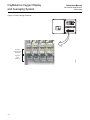
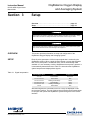
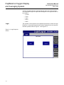
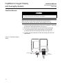
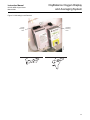
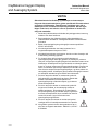
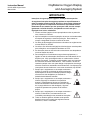
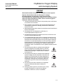
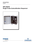
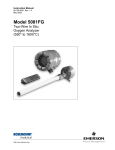
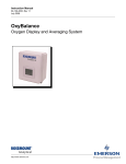
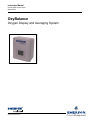
Instruction Manual
IM-106-4050 Original Issue
March 2006
OxyBalance
Oxygen Display and Averaging System
http://www.raihome.com
Instruction Manual
IM-106-4050 Original Issue
March 2006
OxyBalance Oxygen Display
and Averaging System
Table of Contents
Essential Instructions. . . . . . . . . . . . . . . . . . . . . . . . . . . . . . . . . . . . . . . . i
Preface . . . . . . . . . . . . . . . . . . . . . . . . . . . . . . . . . . . . . . . . . . . . . . . . . . ii
Definitions . . . . . . . . . . . . . . . . . . . . . . . . . . . . . . . . . . . . . . . . . . . . . . . . ii
Symbols . . . . . . . . . . . . . . . . . . . . . . . . . . . . . . . . . . . . . . . . . . . . . . . . . . ii
SECTION 1
Description
Component Checklist. . . . . . . . . . . . . . . . . . . . . . . . . . . . . . . . . . . . . . 1-1
Part Numbers. . . . . . . . . . . . . . . . . . . . . . . . . . . . . . . . . . . . . . . . . . . . 1-1
System Overview. . . . . . . . . . . . . . . . . . . . . . . . . . . . . . . . . . . . . . . . . 1-2
General. . . . . . . . . . . . . . . . . . . . . . . . . . . . . . . . . . . . . . . . . . . . . . 1-2
OxyBalance System Features . . . . . . . . . . . . . . . . . . . . . . . . . . . . 1-2
Physical Description . . . . . . . . . . . . . . . . . . . . . . . . . . . . . . . . . . . . 1-3
Specifications. . . . . . . . . . . . . . . . . . . . . . . . . . . . . . . . . . . . . . . . . . . . 1-5
SECTION 2
Installation
Overview . . . . . . . . . . . . . . . . . . . . . . . . . . . . . . . . . . . . . . . . . . . . . . . 2-1
System Considerations . . . . . . . . . . . . . . . . . . . . . . . . . . . . . . . . . . . . 2-1
Mounting . . . . . . . . . . . . . . . . . . . . . . . . . . . . . . . . . . . . . . . . . . . . . . . 2-2
Wiring Connections . . . . . . . . . . . . . . . . . . . . . . . . . . . . . . . . . . . . . . . 2-2
Setup . . . . . . . . . . . . . . . . . . . . . . . . . . . . . . . . . . . . . . . . . . . . . . . . . . 2-2
. . . . . . . . . . . . . . . . . . . . . . . . . . . . . . . . . . . . . . . . . . . . . . . . . . . . . . . 2-4
SECTION 3
Setup
Overview . . . . . . . . . . . . . . . . . . . . . . . . . . . . . . . . . . . . . . . . . . . . . . . 3-1
Setup . . . . . . . . . . . . . . . . . . . . . . . . . . . . . . . . . . . . . . . . . . . . . . . . . . 3-1
Login. . . . . . . . . . . . . . . . . . . . . . . . . . . . . . . . . . . . . . . . . . . . . . . . 3-2
Setup . . . . . . . . . . . . . . . . . . . . . . . . . . . . . . . . . . . . . . . . . . . . . . . 3-4
Current . . . . . . . . . . . . . . . . . . . . . . . . . . . . . . . . . . . . . . . . . . . . . . 3-7
Trend . . . . . . . . . . . . . . . . . . . . . . . . . . . . . . . . . . . . . . . . . . . . . . . 3-9
Alarm . . . . . . . . . . . . . . . . . . . . . . . . . . . . . . . . . . . . . . . . . . . . . . 3-10
SECTION 4
Calibration
OxyBalance Calibration . . . . . . . . . . . . . . . . . . . . . . . . . . . . . . . . . . . . 4-1
SECTION 5
Maintenance and Service
Overview . . . . . . . . . . . . . . . . . . . . . . . . . . . . . . . . . . . . . . . . . . . . . . . 5-1
PanelView Plus 600. . . . . . . . . . . . . . . . . . . . . . . . . . . . . . . . . . . . . . . 5-1
PanelView Removal . . . . . . . . . . . . . . . . . . . . . . . . . . . . . . . . . . . . 5-2
PanelView Installation . . . . . . . . . . . . . . . . . . . . . . . . . . . . . . . . . . 5-4
MicroLogix 1200 Programmable Controllers . . . . . . . . . . . . . . . . . . . . 5-6
PLC Removal . . . . . . . . . . . . . . . . . . . . . . . . . . . . . . . . . . . . . . . . . 5-6
PLC Replacement . . . . . . . . . . . . . . . . . . . . . . . . . . . . . . . . . . . . . 5-8
I/O Module Removal. . . . . . . . . . . . . . . . . . . . . . . . . . . . . . . . . . . . 5-9
I/O Module Replacement . . . . . . . . . . . . . . . . . . . . . . . . . . . . . . . . 5-9
SECTION 6
Troubleshooting
Overview . . . . . . . . . . . . . . . . . . . . . . . . . . . . . . . . . . . . . . . . . . . . . . . 6-1
Probe Failure . . . . . . . . . . . . . . . . . . . . . . . . . . . . . . . . . . . . . . . . . . . . 6-1
TOC-1
Instruction Manual
IM-106-4050 Original Issue
March 2006
SECTION 7
Recommended Spare
Parts
OxyBalance Oxygen Display
and Averaging System
Spare Parts Listing . . . . . . . . . . . . . . . . . . . . . . . . . . . . . . . . . . . . . . . 7-1
SECTION 8
Optional Accessories
APPENDIX A
Safety Data
Safety Instructions . . . . . . . . . . . . . . . . . . . . . . . . . . . . . . . . . . . . . . . . A-2
SECTION B
Returning Equipment to
the Factory
Returning Material . . . . . . . . . . . . . . . . . . . . . . . . . . . . . . . . . . . . . . . . B-1
TOC-2
Instruction Manual
IM-106-4050 Original Issue
March 2006
OxyBalance Oxygen Display
and Averaging System
OxyBalance
Oxygen Display and Averaging System
READ THIS PAGE BEFORE PROCEEDING!
ESSENTIAL
INSTRUCTIONS
Emerson process Management designs, manufactures and tests its products
to meet many national and international standards. Because these
instruments are sophisticated technical products, you MUST properly
install, use, and maintain them to ensure they continue to operate within
their normal specifications. The following instructions MUST be adhered to
and integrated into your safety program when installing, using, and
maintaining Rosemount Analytical products. Failure to follow the proper
instructions may cause any one of the following situations to occur: Loss of
life; personal injury; property damage; damage to this instrument; and
warranty invalidation.
• Read all instructions prior to installing, operating, and servicing the
product.
• If you do not understand any of the instructions, contact your
Rosemount Analytical representative for clarification.
• Follow all warnings, cautions, and instructions marked on and
supplied with the product.
• Inform and educate your personnel in the proper installation,
operation, and maintenance of the product.
• Install your equipment as specified in the Installation Instructions
of the appropriate Instruction Manual and per applicable local and
national codes. Connect all products to the proper electrical and
pressure sources.
• To ensure proper performance, use qualified personnel to install,
operate, update, program, and maintain the product.
• When replacement parts are required, ensure that qualified people use
replacement parts specified by Rosemount Analytical. Unauthorized
parts and procedures can affect the product's performance, place the
safe operation of your process at risk, and VOID YOUR WARRANTY.
Look-alike substitutions may result in fire, electrical hazards, or
improper operation.
• Ensure that all equipment doors are closed and protective covers
are in place, except when maintenance is being performed by
qualified persons, to prevent electrical shock and personal injury.
The information contained in this document is subject to change without
notice.
http://www.processanalytic.com
OxyBalance Oxygen Display
and Averaging System
Instruction Manual
IM-106-4050 Original Issue
March 2006
If a Model 275/375 Universal HART® Communicator is used with this unit, the software
within the Model 275/375 may require modification. If a software modification is required,
please contact your local Emerson process Management Service Group or National
Response Center at 1-800-433-6076 or 1-888-433-6829.
PREFACE
The purpose of this manual is to provide information concerning the
components, functions, installation and maintenance of the OxyBalance
Oxygen Display and Average System.
Some sections may describe equipment not used in your configuration. The
user should become thoroughly familiar with the operation of this module
before operating it. Read this instruction manual completely.
DEFINITIONS
The following definitions apply to WARNINGS, CAUTIONS, and NOTES
found throughout this publication.
Highlights an operation or maintenance procedure, practice, condition, statement, etc. If not
strictly observed, could result in injury, death, or long-term health hazards of personnel.
Highlights an operation or maintenance procedure, practice, condition, statement, etc. If not
strictly observed, could result in damage to or destruction of equipment, or loss of
effectiveness.
NOTE
Highlights an essential operating procedure, condition, or statement.
SYMBOLS
: EARTH (GROUND) TERMINAL
: PROTECTIVE CONDUCT OR TERMINAL
: RISK OF ELECTRICAL SHOCK
: WARNING: REFER TO INSTRUCTION MANUAL
NOTE TO USERS
The number in the lower right corner of each illustration in this publication is a
manual illustration number. It is not a part number, and is not related to the
illustration in any technical manner.
ii
OxyBalance Oxygen Display
and Averaging System
Instruction Manual
IM-106-4050 Original Issue
March 2006
Section 1
Description
Component Checklist . . . . . . . . . . . . . . . . . . . . . . . . . . . . . page 1-1
Part Numbers . . . . . . . . . . . . . . . . . . . . . . . . . . . . . . . . . . . page 1-1
System Overview . . . . . . . . . . . . . . . . . . . . . . . . . . . . . . . . page 1-2
Specifications . . . . . . . . . . . . . . . . . . . . . . . . . . . . . . . . . . . page 1-5
COMPONENT
CHECKLIST
A typical Rosemount Analytical OxyBalance Oxygen Display and Averaging
System package should contain the items shown in Figure 1-1.
PART NUMBERS
Use the part numbers listed in Table 1-1 to verify your OxyBalance system
part number. Copy the part number and serial number from the
OxyBalanceunit into the chart on the back cover of this manual. Refer tothis
complete part number for any correspondence with Emerson Process
Management.
Table 1-1. OxyBalance System
Part Numbers
Part Number
Description
6A00203G01
1-4 probes, NEMA 4X enclosure
6A00203G02
5-8 probes, NEMA 4X enclosure
6A00203G03
1-4 probes, plate mounted
6A00203G04
5-8 probes, plate mounted
Figure 1-1. Typical System
Package
1
Instr
IM-1 uctio
n
Dece06-340CManual
mbe
Rev.
r 2005
4.2
OX
YM
IT
HA
ZA
OX RDOUTER
YG
EN S AR4000
TRAN EA
SM
ITT
ER
2
tic
al
An
aly
tic
al
38370006
An
aly
1. Instruction Manual
2. OxyBalance Oxygen Display and Averaging System
http://www.processanalytic.com
OxyBalance Oxygen Display
and Averaging System
Instruction Manual
IM-106-4050 Original Issue
March 2006
SYSTEM OVERVIEW
General
The OxyBalance is a display and averaging system that augments the
Oxymitter O2 probe product line. It receives up to (8) 4-20 mA signals from
Rosemount, Westinghouse, or other O2 probes, and calculates and transmits
up to 4 additional programmable averages (again 4-20 mA). The OxyBalance
system also displays the individual and averaged outputs on a color touch
screen graphic panel. Trend screens, bar graphs (individual probes only), and
alarming indications are provided when a probe goes off line.
The OxyBalance system replaces much of the functionality of older averaging
systems offered by Westinghouse and Rosemount - the Control Room
Electronics (CRE), 1500 Controller-based averaging systems, and the
Veritrak-based 1290 systems. It should be noted, however, that the heater
control and signal conditioning for each individual probe is executed within
separate electronics for each probe. Unlike past averaging systems, and most
current competitive averaging systems, there is no component failure in the
OxyBalance system that will cause the loss of individual probe signals.
The OxyBalance system senses 4-20 mA inputs automatically. Averages are
very easy to set up. Any probes that may fail will default to a 3.5 mA signal
level, indicate in red, and the OxyBalance system will remove these probes
from the average. Likewise, probes that are in calibration will indicate blue,
and provide a contact closure to the OxyBalance system to remove them from
the average while calibrating.
Trends offer adjustable scaling, three time spans (5 min., 8 hrs., and 24 hrs.),
and panning capability back and forth in history.
OxyBalance System
Features
The standard OxyBalance system includes the following features:
• Graphically displays and trends from 1 to 8 O2 measurements.
• Probe inputs may be from Rosemount Analytical, Westinghouse or any
competitive O2 probe with a 4-20 mA signal output.
• Generates up to four 4-20 mA signals as programmable averages.
• Failed or calibrating probes are automatically removed from the
average
• Individual probe readings remain autonomous and are unaffected by
any potential failure of the OxyBalance system.
• Variable time scale trends for each individual probe value, as well as for
up to 4 averages.
• Password protection for set up menus.
1-2
OxyBalance Oxygen Display
and Averaging System
Instruction Manual
IM-106-4050 Original Issue
March 2006
Physical Description
Aside from the PanelView Plus 600, the OxyBalance system consists of
iadditional components mounted on three DIN rails. The main components
are shown in Figure 1-2.
PanelView Plus 600
The PanelView Plus 600 is the touch screen interface located on the front of
the OxyBalance system, all probe readings and averages are displayed
through this interface. There is also a power cord and communications cord
that connect to this module.
MicroLogix 1200 Programmable Logic Controller
PLC
The PLC process the raw data received by the OxyBalance. The
processed data is transmitted to the PanelView Plus 600, where it is
displayed on the touch screen interface.
I/O Modules
Also known as the expansion I/O, these modules act as part of the
controller system and are located on the right side of the PLC unit.
Input Terminals
This row of terminals receives the 4-20 mA signals from the O2 probes.
Figure 1-2. OxyBalance Components
Power
Terminals
MicroLogix 1200
Programmable
Logic Controller
I/O Modules
PLC
Failure
Terminals
POWER
RUN
FAULT
FORCE
COMM 0
DCOMM
IN
0 1 2 3
5 6
7 13
8 9 104 11 12
0 1 2 43
5 76
8 9
OUT
0
0
1
1
2
3
0
1
2
2
3
3
4
4
4
5
5
5
6
6
6
7
7
7
Failure/
Warning
Terminals
PanelView
Plus 600
Signal Pass
Through Terminals
Input
Terminals
Output
Terminals
38370016
In Cal
Terminals
1-3
OxyBalance Oxygen Display
and Averaging System
Instruction Manual
IM-106-4050 Original Issue
March 2006
Signal Pass Through Terminals
The pass through terminals are located on the input terminals. These
terminals provide connection points for passing on the incoming O2 signal to
other devices.
Output (Average) Terminals
These terminals provide a connection point for the average O2% 4-20 mA
signals.
Failure / Warning Terminals
These terminals provide connection points for the output signal warning and
failure contacts.
In Cal Terminals
These terminals provide connection points for In Cal signals from the
individual oxygen probes. When a probe is in calibration, it is removed from
any average calculations.
Power Terminals
This terminal provides wire contacts for power distribution in the OxyBalance
system.
OxyBalance operating specifications are listed in Table 1-2.
1-4
OxyBalance Oxygen Display
and Averaging System
Instruction Manual
IM-106-4050 Original Issue
March 2006
SPECIFICATIONS
Specifications for the OxyBalance system are listied in Table 1-2.
Table 1-2. OxyBalance Specifications
SPECIFICATIONS(1)
Ambient Environment
Temperature specification
23oF to 149o F (-5oC to 65oC)
Ambient temperature effect on electronics
Less than .01% of reading per 10oC
Vibration
IEC 68-2-6 and ISA S37.3
Shock
IEC 68-2-31 and ISA S37.3
Enclosure
NEMA 4X
Area Classification
General Purpose
Power Requirements
100-240 VAC, 50/60 Hz
MicroLogix 1200
Resistive Load on Current Output
0 to 500 Ohms (includes wire resistance)
Input Impedance for Current Terminal
275 Ohms
PanelView Plus 600
Minimum On-State Current
2.0 mA at 10V dc
Nominal On-State Current
8.9 mA at 24V dc
Maximum On-State Current
12. mA at 30V dc
Current per Group Common
8A
240V ac (Maximum Volts)
2.5A(2) (Amperes Continuous)
120V ac (Maximum Volts)
2.5A(2) (Amperes Continuous)
125V dc (Maximum Volts)
1.0A (Amperes Continuous)
24V dc (Maximum Volts)
2.0A (Amperes Continuous)
Signal Inputs
4-20 mA (qty. 1 to 8 O2 probes)
I/O
Signal Outputs
4-20 mA (qty, 1 to 8 pass through each probe, qty. 4 programmable averages)
Signal Output Resolution (for averages)
12 bit
Signal Output Resistive Load
Less than 500 ohms
Discrete Inputs
"IN CAL" (qty. 2 to 8 from individual probes)
Relay Outputs
"LOSS OF PLC"
"AVERAGE WARN" if one or more probes drop out of an average.
"AVERAGE FAILED" for each average when only one probe in the average
remains valid.
Architecture
Each probe utilizes its own autonomous conditioning electronics, including its
own power supply. Any failure in the OxyBalance system will not affect the
individual 4-20 mA signals going to the control room for each probe.
Logic
4 programmable averages from 2-8 probes
1.) Probe fails (4-20 mA to default condition of 3.5 mA or 21 mA
2.) Probe is in cal (SPS / IMPS contact, must share with control room)
Individual probes removed from average if
Signal Security
4-20 mA signals to be wired in series to the PLC and to the DCS I/O marshalling
panel such that the loss of the PLC will not affect the transmission of the
individual probe signals to the DCS. If PLC power, I/O cards or processor card(s)
are lost, 4-20 mA signals from the probes are still transmitted to the control room.
Personnel Security
Password protection configuration changes in programmable averages.
Color Graphic Display
Size
6" diagonal
Type
Color Active Matrix, TFT LCD
Resolution
320 by 240 min. Touch screen operator interface
(1)
Specifications are subject to change without notification. Our policy is one of continuous
improvement and we reserve the right to change specifications.
1.5A above 40oC.
(2)
1-5
OxyBalance Oxygen Display
and Averaging System
1-6
Instruction Manual
IM-106-4050 Original Issue
March 2006
OxyBalance Oxygen Display
and Averaging System
Instruction Manual
IM-106-4050 Original Issue
March 2006
Section 2
Installation
Overview . . . . . . . . . . . . . . . . . . . . . . . . . . . . . . . . . . . . . . . page 2-1
System Considerations . . . . . . . . . . . . . . . . . . . . . . . . . . . page 2-1
Mounting . . . . . . . . . . . . . . . . . . . . . . . . . . . . . . . . . . . . . . . page 2-2
Wiring Connections . . . . . . . . . . . . . . . . . . . . . . . . . . . . . . page 2-2
Setup . . . . . . . . . . . . . . . . . . . . . . . . . . . . . . . . . . . . . . . . . . page 2-2
Before starting to install this equipment, read the "Safety Instructions" in Appendix A: Safety
Data. Failure to follow the safety instructions could result in serious injury or death.
Disconnect all power before installing or replacing components. Failure to disconnect power
may result in electrical shock and/or damage to the terminal.
Install all protective equipment covers and safety ground leads after installation. Failure to
secure covers and ground leads could result in serious injury or death.
OVERVIEW
This section describes:
1. Wall-mounting of the OxyBalance system.
2. The necessary wiring schematics for proper connection of the
OxyBalance system.
3. Setup procedures conducted through the PanelView Plus 600 on how to
configure, assign nomenclature, change/update display settings, and
assigning the O2 probes to the average outputs.
SYSTEM
CONSIDERATIONS
http://www.processanalytic.com
Prior to installation of the OxyBalance system, check for all components
necessary to install the system completely. When selecting a mounting
location, determine where the OxyBalance system will be placed in terms of
serviceability, ambient temperatures, environmental considerations, and
convenience.
OxyBalance Oxygen Display
and Averaging System
MOUNTING
Instruction Manual
IM-106-4050 Original Issue
March 2006
The OxyBalance Oxygen Display and Averaging System was designed to be
wall-mounted or simply placed on a table. Locate the unit where the ambient
temperature is between 23oF to 149oF (-5oC to 65oC).
The outline drawing in Figure 2-1 shows mounting dimensions of the
OxyBalance system.
Figure 2-1. Mounting Dimensions
12.00
(304,8)
Note:
All dimensions are
in inches with millimeters
in parentheses.
38370002
17.12
(434,8)
WIRING CONNECTIONS
Refer to Figure 2-2 and connect the input and output signal wiring to the
OxyBalance as follows:
1. Connect the incoming 4-20mA signals to the input signal terminals.
2. Connect the 4-20mA average O2 signals to the output signal terminals.
3. Connect the In Cal input signals to the in cal signal terminals.
4. Connect the warning and failure signal output wiring to the warning and
failure signal terminals.
5. If the signal pass-through feature for the incoming O2 signals will be
used, remove the jumpers from the pass-through terminals. Connect the
outgoing O2 signal wires to the raised output signal terminals. Refer to
Figure 2-3.
6. Connect 90-240Vac, 50/60 Hz input power to the power input terminals.
SETUP
2-2
For setup information, refer to Section 3, Setup.
OxyBalance Oxygen Display
and Averaging System
Instruction Manual
IM-106-4050 Original Issue
March 2006
Figure 2-2. Installation Wiring Schematic
Avg 4 Warning
Avg 3 Warning
Avg 2 Warning
Avg 1 Warning
Avg Warning Common
In Cal
Contacts
Avg 4 Fail
Avg 3 Fail
Avg 3&4 Fail Common
Avg 2 Fail
Avg 1 Fail
Avg 1&2 Fail Common
PLC Failure
Probe 8
Probe 7
Probe 6
Probe 5
Probe 4
Probe 3
Probe 2
Probe 1
Ground
Neutral
Line
Line
Voltage
POWER
RUN
FAULT
FORCE
COMM 0
DCOMM
IN
0 1 2 3
5 6
7 13
8 9 104 11 12
0 1 2 43
5 76
8 9
OUT
0
0
0
1
1
1
2
3
2
3
3
4
4
5
5
6
6
6
7
7
7
Average 4-20 mA
Output Signals
38370003
Average 4
Average 3
Average 2
Average 1
2-3
Probe 8
Incoming 4-20 mA
O2 Signals
Probe 7
Probe 6
Probe 5
Probe 4
Probe 1
Probe 3
+- +- +- +-
Probe 2
+- +- +- +- +- +- +- +-
2
4
5
OxyBalance Oxygen Display
and Averaging System
Instruction Manual
IM-106-4050 Original Issue
March 2006
Figure 2-3. Pass-Through Terminals
POWER
RUN
FAULT
FORCE
COMM 0
DCOMM
IN
0 1 2 3
5 6
7 13
8 9 104 11 12
0 1 2 43
5 76
8 9
OUT
0
0
0
1
1
1
2
2
2
3
3
3
4
4
5
5
6
6
6
7
7
7
4
5
4-20 mA
Input
Terminals
2-4
38370015
4-20 mA
Pass-Through
Terminals
OxyBalance Oxygen Display
and Averaging System
Instruction Manual
IM-106-4050 Original Issue
March 2006
Section 3
Setup
Overview . . . . . . . . . . . . . . . . . . . . . . . . . . . . . . . . . . . . . . . page 3-1
Setup . . . . . . . . . . . . . . . . . . . . . . . . . . . . . . . . . . . . . . . . . . page 3-1
Before starting to install this equipment, read the "Safety Instructions" in Appendix A: Safety
Data. Failure to follow the safety instructions could result in serious injury or death.
Disconnect all power before installing or replacing components. Failure to disconnect power
may result in electrical shock and/or damage to the equipment.
OVERVIEW
This section provides information on setup and configuration of the
OxyBalance Oxygen Display and Averaging System
SETUP
Each O2 probe generates a 4-20 mA output signal that is received by the
OxyBalance system. When a probe channel detects a current signal greater
than 3.5 mA, that probe is considered active, and is automatically made
available. It is not necessary to tell the OxyBalance that a probe is present. It
is automatically detected and used. Table 3-1 shows how the OxyBalance
system interprets and displays these signals.
Table 3-1. Signal Interpretation
4-20 mA Signal Value
Status
Display Color
<3.5 mA
Not Shown
3.5 mA to 3.6 mA
Probe Inactive
Probe Failed
3.6 mA to 3.8 mA
Reading Under Range
Yellow
Red
3.8 mA to 20.5 mA
Good Reading
Green
20.5 mA to 21 mA
Reading Over Range
Yellow
>21 mA
Probe Failed
Red
After these signals are converted into an O2 % they are displayed on the
touch screen interface. The rest of this section will outline the necessary steps
to configure and operate the OxyBalance system through the touch screen
interface.
http://www.processanalytic.com
OxyBalance Oxygen Display
and Averaging System
Instruction Manual
IM-106-4050 Original Issue
March 2006
All of the operations that are conducted through the touch screen interface,
are conducted through five subject tabs that appear on the right hand side of
the interface.
• Current
• Trend
• Login
• Setup
• Alarm
Login
Figure 3-1. Login Required
Screen
3-2
The operation of the interface can be password protected, so either the Login
Required, or Login Not Required screen will be displayed once the Login tab
has been pressed, Refer to Figure 3-1 and Figure 3-2.
Instruction Manual
IM-106-4050 Original Issue
March 2006
OxyBalance Oxygen Display
and Averaging System
Figure 3-2. Login Not
Required Screen
3-3
OxyBalance Oxygen Display
and Averaging System
Setup
Instruction Manual
IM-106-4050 Original Issue
March 2006
The Setup tab continas five sub-tabs displayed along the top of the screen; a
General tab, and one tab for each of the four averages.
General
Scale Values
Under this tab the values for the Analog full scale, Trend min value and
Trend max value, can be changed to represent more of an applicable
scale when displaying the probe or average outputs. See Figure 3-3.
• Analog full scale - This setting controls the O2 % value represented by
the incoming 4-20 mA signals, and the average O2 % output signals. All
input signals must represent the same full scale value.
• Trend min value - This values allows the adjustment of the minimum
value displayed on the trend graphs on the touch screen display,
allowing the display to zoom in on the range of interest. This setting
only affects the displayed values. It has no affect on the average O2 %
output signals.
• Trend max value - This values allows the adjustment of the maximum
value displayed on the trend graphs on the touch screen display,
allowing the display to zoom in on the range of interest. This setting
only affects the displayed values. It has no affect on the average O2 %
output signals.
Figure 3-3. Scale Values Setup
3-4
Instruction Manual
IM-106-4050 Original Issue
March 2006
OxyBalance Oxygen Display
and Averaging System
Time and Date
To set the time and date press the "Time/Date" button shown on the
General tab of the Setup screen. A new screen will be shown. See
Figure 3-4. Touch any value in the Actual column to change that value.
Once the new value has been entered, hold the "Hold To Set Clock" button
until the time and date has been updated in the upper right hand corner of
the screen.
Figure 3-4. Time and Date Setup
3-5
OxyBalance Oxygen Display
and Averaging System
Instruction Manual
IM-106-4050 Original Issue
March 2006
Average1 - Average4
The four Average tabs across the top of the Setup screen represent the four
output signals generated by the Oxybalance system. Each of these four tabs
displays all eight possible input signals, whether or not the probes are active,
and whether or not they have been selected to be part of the average for the
selected output chanel. In Figure 3-5 the information for Average2 is shown.
In Figure 3-5, this channel has been named "Duct B". This name can be
changed by pressing the name on the screen. Probes 2 thourgh 8 are active.
Probes 4, 5 and 6 have been selected to be included in this channel. Pressing
on any of the active probes will toggle the probe between being included and
not included in this channel average. Once a probe is assigned to the
displayed average group, the background for that probe is shown in green.
Two to eight probes can be assigned to any of the average groups, in any
combination.
Figure 3-5. Average Setup
3-6
OxyBalance Oxygen Display
and Averaging System
Instruction Manual
IM-106-4050 Original Issue
March 2006
Current
Selecting the Current tab on the right side of the touch screen will display the
Current screen. The two tabs at the top of the screen will display the Probes
and Averages information.
Probes
The Probes tab, shown in Figure 3-6, displays the status and the oxygen
percentage for each of the eight possible probes. The color of the bar denotes
the status of the probe signal.
• Green = Probe is OK
• Blue = Probe is in calibration
• Red = Probe has failed
• Yellow = Analog input signal is outside the normal range, but not far
enough to be considered failed.
NOTE
If a probe signal level is not shown in green, then it is not being used in any
average calculations.
Figure 3-6 provides an example of a Probes tab with probes in several of
these conditions. Probe 1 is in Fault condintion, and probe 5 is in calibration.
Neither of these probes will be used in any average calculations.
Figure 3-6. Probes Tab
3-7
OxyBalance Oxygen Display
and Averaging System
Instruction Manual
IM-106-4050 Original Issue
March 2006
Averages
The Averages tab of the Current screen, shown in Figure 3-7, displays the
average oxygen percentage for each probe grouping. Each of these four
averages are represented by either a green or red status tag and bar. Green
signifies that the average is OK, red means that the reading is either in a fault
or warning condition.
Fault Condition
A Fault condition is indicated when one or more probes included in an
average has failed. The failed probes are not included in the average
calculation for that average.
Warning Condition
A warning condition occurs for an average when only all but one channel
included in an average is in a failed state. In this state, an "average"
cannont be calculated, and the channel will output the value of the
remaining functional probe.
Figure 3-7. Average Current
3-8
OxyBalance Oxygen Display
and Averaging System
Instruction Manual
IM-106-4050 Original Issue
March 2006
Trend
The Trend tab represents a graphical trend analysis of the oxygen percentage
for all eight probes, and the oxygen percentage for all four averages.
The LEFT and RIGHT buttons at the bottom of the screen scroll the trend
graph, allowing access to historical data.
The button labeled 5 min in the top right corner changes the display scale
between 5 minutes, 1 hour, and 24 hours. Pressing the button cycles through
the available options.
All
The "All" tab graphically represents each of the four averages, all signified in a
different color for display purposes only.
Average1- Average4
Each of these four tabs shows a single average channel, and all of the probes
included in that average.
Figure 3-8 shows the Average4 tab. This average grouping has been named
Total, and shows the readings for all eight probes, which are represented on
the trend graph by a separate color for each probe. The average for this
channel is shown above the trend graph, to the left of the channel name.
The LEFT and RIGHT buttons scroll the trend graph, allowing access to
historical data.
The button labeled 5 min in the top right corner changes the display scale
between 5 minutes, 1 hour, and 24 hours. Pressing the button cycles through
the available options.
Figure 3-8. Probe Trend
3-9
OxyBalance Oxygen Display
and Averaging System
Alarm
Instruction Manual
IM-106-4050 Original Issue
March 2006
There are two divisions of the Alarm tab: Active Alarms and Alarm History,
shown in Figure 3-9 and Figure 3-10.
There are four possible reports that can be displayed.
Average # 1-4 warning
This appears when one of the probes fails or is in calibration. When this Alarm
appears, the average channel will still display an average O2 % for the
remaining probes in the group.
Average # 1-4 failed
This appears when less than 2 probes in the group are transmitting data for
the average calculation. No average percentage will be calculated.
Probe # 1-8 calibration in progress
This means that the probe is calibrating and will automatically join its specified
group when the calibration is complete. Probes in calibration are not factored
into the channel average.
Probe #1-8 failed
This means the probe has failed and needs to be checked. Refer to Section 6,
Troubleshooting.
Figure 3-9. Active Alarms
3-10
Instruction Manual
IM-106-4050 Original Issue
March 2006
OxyBalance Oxygen Display
and Averaging System
Figure 3-10. Alarm History
On the Alarm History page, shown in Figure 3-10, there are three sets of
arrows used for selecting the alarms. These are located in the bottom center
portion of the screen. To scroll between individual alarms use the set of
arrows on the right. To jump to the next or previous page of alarms use the
middle set of arrows. To jump to the top or bottom of the list, use the set of
arrows on the left side. These are also shown on the Active Alarms page.
The Ack Alm and Ack All buttons are used to acknowledge the alarms.
Acknowledging alarms has no effect on the operation of the system. It is an
aide for determining which alarms have and have not been seen. Once an
alarm has been acknowledged, by using either the Ack Alarm or Ack All
button, an asterisk appears next to the date and time of the alarm.
3-11
OxyBalance Oxygen Display
and Averaging System
3-12
Instruction Manual
IM-106-4050 Original Issue
March 2006
Instruction Manual
IM-106-4050 Original Issue
March 2006
Section 4
OxyBalance Oxygen Display
and Averaging System
Calibration
OxyBalance Calibration . . . . . . . . . . . . . . . . . . . . . . . . . . . page 4-1
OXYBALANCE
CALIBRATION
http://www.processanalytic.com
There is no calibration required for the OxyBalance Oxygen Display and
Averaging System.
OxyBalance Oxygen Display
and Averaging System
4-2
Instruction Manual
IM-106-4050 Original Issue
March 2006
Instruction Manual
IM-106-4050 Original Issue
March 2006
Section 5
OxyBalance Oxygen Display
and Averaging System
Maintenance and Service
Overview . . . . . . . . . . . . . . . . . . . . . . . . . . . . . . . . . . . . . . . page 5-1
PanelView Plus 600 . . . . . . . . . . . . . . . . . . . . . . . . . . . . . . page 5-1
MicroLogix 1200 Programmable Controllers . . . . . . . . . . page 5-6
Before starting to install this equipment, read the "Safety Instructions" in Appendix A: Safety
Data. Failure to follow the safety instructions could result in serious injury or death.
Disconnect all power before installing or replacing components. Failure to disconnect power
may result in electrical shock and/or damage to the equipment.
Install all protective equipment covers and safety ground leads after installation. Failure to
secure covers and ground leads could result in serious injury or death.
OVERVIEW
This section describes the removal and replacement of the PanelView Plus
600 and the MicroLogix 1200 Programmable Controllers.
PANELVIEW PLUS 600
The PanelView Plus 600 touch screen interface is visible through the front
panel cutout. The internal circuitry is housed inside the NEMA 4X protective
enclosure.
The PanelView comes equipped with the following features:
• AC or DC power connection and cord
• Mounting lever slots
• RS-232 and USB ports
• Touch screen interface
• Communication module and cord
• Compact flash memory card slot
http://www.processanalytic.com
OxyBalance Oxygen Display
and Averaging System
Instruction Manual
IM-106-4050 Original Issue
March 2006
PanelView Removal
Disconnect all power before installing or replacing components. Failure to disconnect power
may result in electrical shock and/or damage to the equipment.
NOTE
Make sure to record the wiring connections and locations before
disconnecting any wiring. This will aid in the installation of the unit.
1. Disconnect the three power wires from the wire contacts (L1, L2N, and
ground) of the PanelView Plus 600, see Figure 5-1.
2. Remove the communications cord from the PanelView Plus 600.
3. Turn mounting levers to the unlocked position, and remove the
mounting levers from the mounting lever slots. See Figure 5-3.
4. Carefully slide the PanelView Plus 600 unit through the front of the
panel cutout.
38370010
Figure 5-1. PanelView System
Wiring
Communications
Cable
5-2
Power
Connection
Instruction Manual
IM-106-4050 Original Issue
March 2006
OxyBalance Oxygen Display
and Averaging System
Figure 5-2. Mounting Lever Removal
Locked
Mounting
Lever
38370017
Unlocked
Mounting
Lever
5-3
OxyBalance Oxygen Display
and Averaging System
Instruction Manual
IM-106-4050 Original Issue
March 2006
PanelView Installation
This equipment is intended for use in clean, dry environments where only non-conductive
pollution occurs (except occasionally a temporary conductivity caused by condensation),
and with circuits not exceeding Over Voltage Category II (IEC 60664-1).
Disconnect all power before installing or replacing components. Failure to disconnect power
may result in electrical shock and/or damage to the equipment.
Mounting Procedures
NOTE
If a communication module is ordered separately, make sure to attach the
module to the base unit before panel installation. Refer to the PanelView Plus
600 manual for information on communication modules.
NOTE
Make sure the sealing gasket is properly positioned on the PanelView Plus
600. This gasket forms a compression seal. DO NOT use sealing compounds.
1. Insert the PanelView Plus 600 through the panel cutout on the front of
the NEMA 4X protective enclosure front panel. Make sure to align the
unit with the center of the panel cutout for adequate gasket sealing.
2. Insert the four mounting levers into the mounting slots on the unit, see
Figure 5-3. Slide each lever until the flat side of the lever touches the
surface of the panel.
3. Once all levers are in place, slide each lever an additional notch or two
until you hear a click.
4. Rotate each lever in the direction indicated until it is in the final latch
position.
5. Connect the power wires to the three wire contacts (L1, L2N, and
ground) on the PanelView Plus 600. see Figure 5-1.
6. Connect the communication cord to the PanelView Plus 600.
5-4
Instruction Manual
IM-106-4050 Original Issue
March 2006
OxyBalance Oxygen Display
and Averaging System
Figure 5-3. Mounting Levers Installation
Unlocked
Mounting
Lever
38370011
Locked
Mounting
Lever
5-5
Instruction Manual
IM-106-4050 Original Issue
March 2006
MICROLOGIX 1200
PROGRAMMABLE
CONTROLLERS
OxyBalance Oxygen Display
and Averaging System
The MicroLogix 1200 Programmable Controllers consist of one PLC unit and
three I/O modules. The PLC mounts horizontally with the expansion I/O
modules extending to the right of the controller.
This equipment is intended for use in clean, dry environments where only non-conductive
pollution occurs (except occasionally a temporary conductivity caused by condensation),
and with circuits not exceeding Over Voltage Category II (IEC 60664-1).
Electrostatic discharge can damage semiconductor devices inside the controller. Do not
touch connector pins and other sensitive areas.
PLC Removal
Disconnect all power before installing or replacing components. Failure to disconnect power
may result in electrical shock and/or damage to the equipment.
NOTE
Make sure to carefully record the wiring connections and locations before
disconnecting. This will aid in the installation of the unit.
1. Tag and disconnect all wiring from the MicroLogix PLC.
2. Remove the cover from the ribbon cable connector on the PLC. Use the
pull loop on the connector to disconnect the ribbon cable from the PLC.
Do not pull on the ribbon cable. See Figure 5-4.
3. Place a flat-blade screw driver in the DIN rail tab at the bottom of the
controller, see Figure 5-5. Holding the PLC, pry downward on the tab
until the tab locks in the open position.
4. Repeat step 3 for the second DIN rail tab.
5. Pull the bottom of the PLC out and away from DIN Rail, as shown in
Figure 5-6. When the bottom of the PLC is free from the DIN rail, lift up
on the PLC until the top is also free of the DIN rail. Remove the PLC
from the OxyBalance enclosure.
5-6
OxyBalance Oxygen Display
and Averaging System
Instruction Manual
IM-106-4050 Original Issue
March 2006
Figure 5-4. Ribbon Cable and Pull Loop
End Anchor
Ribbon
Cables
End Anchor
38370005
Pull Loops
Ribbon
Cable Covers
Figure 5-5. DIN Tabs
POWER
RUN
FAULT
FORCE
COMM 0
DCOMM
IN
0 1 2 3
5 6
7 13
8 9 104 11 12
0 1 2 43
5 76
8 9
OUT
0
0
1
1
2
2
2
3
3
3
4
4
4
5
5
5
6
6
6
7
7
7
closed
38370008
open
0
1
5-7
OxyBalance Oxygen Display
and Averaging System
Instruction Manual
IM-106-4050 Original Issue
March 2006
Figure 5-6. Removal from
DIN Rail
38370007
DIN Rail
PLC Replacement
Mounting Procedures
1. Place the top of the MicroLogix PLC over the top of the DIN rail, with the
bottom fo the PLC tilted away from the DIN rail. See Figure 5-6
2. When the top of the PLC engages the DIN rail, pivot the bottom of the
PLC in toward the DIN rail.
3. Using a screwdriver, push the DIN tabs up until they snap into position,
holding the PLC tight against the DIN rail. See Figure 5-5/
4. Attach the flat ribbon cable from the I/O modules to the PLC. See
Figure 5-4. Install the ribbon cable cover.
5. Ensure the end anchors are tight
6. Connect the wiring to the PLC that was removed in step 1 of "PLC
Removal".
Failure to remove protective debris shield before operating can cause overheating.
7. Remove the debris shield from the PLC.
5-8
OxyBalance Oxygen Display
and Averaging System
Instruction Manual
IM-106-4050 Original Issue
March 2006
I/O Module Removal
Disconnect all power before installing or replacing components. Failure to disconnect power
may result in electrical shock and/or damage to the equipment.
NOTE
Make sure to carefully record the wiring connections and locations before
disconnecting. This will aid in the installation of the unit.
1. Tag and disconnect all wiring from the I/O module.
2. Remove the cover from the ribbon cable connector on the module to the
left of the module to be removed. Use the pull loop on the connector to
disconnect the ribbon cable from that module. Do not pull on the ribbon
cable. See Figure 5-4.
3. If necessary, remove the cover from the ribbon cable connector on the
module to be removed. Use the pull loop on the connector to disconnect
the ribbon cable. Do not pull on the ribbon cable.
4. Place a flat-blade screw driver in the DIN rail tab at the bottom of the I/O
module. Holding the module, pry downward on the tab until the tab locks
in the open position.
5. Pull the bottom of the I/O module out and away from the mounting plate
inside the enclosure. When the bottom of the module is free from the
DIN rail, lift up on the module until the top is also free of the DIN rail.
Remove the module from the OxyBalance enclosure.
I/O Module Replacement
Mounting Procedures
1. Place the top of the I/O module over the top of the DIN rail, with the
bottom fo the module tilted away from the DIN rail.
2. When the top of the module engages the DIN rail, pivot the bottom of
the module in toward the DIN rail.
3. Using a screwdriver, push the DIN tab up until it snaps into position,
holding the module tight against the DIN rail.
4. Attach the flat ribbon cable from the I/O module to the PLC or module to
the left. Install the ribbon cable cover.
5. If necessary, attach the ribbon cable from the I/O module to the right, to
the module being installed. Install the ribbon cable cover.
6. Ensure the end anchors are tight
7. Connect the wiring to the I/O Module that was removed in step 1 of "I/O
Module Removal".
5-9
OxyBalance Oxygen Display
and Averaging System
5-10
Instruction Manual
IM-106-4050 Original Issue
March 2006
Instruction Manual
IM-106-4050 Original Issue
March 2006
Section 6
OxyBalance Oxygen Display
and Averaging System
Troubleshooting
Overview . . . . . . . . . . . . . . . . . . . . . . . . . . . . . . . . . . . . . . . page 6-1
Probe Failure . . . . . . . . . . . . . . . . . . . . . . . . . . . . . . . . . . . . page 6-1
OVERVIEW
This section describes troubleshooting procedures for probe failure in the
OxyBalance system.
Refer to the PanelView Plus 400 and 600 Terminals Installation Instructions or
the MicroLogix 1200 Programmable Controllers User Manual for any
troubleshooting problems concerning these units.
PROBE FAILURE
If the one of the O2 sensing probe is in failure, make sure to check that:
1. All wiring is secure and properly connected to the O2 probe.
2. All wiring is secure and connected to the proper contacts inside the
OxyBalance system.
3. O2 probe is set to transmit a 4-20 mA signal and not set on a different
range , such as 0-20 mA or voltage.
4. All O2 probes are set to output the same O2 range, such as 0-10%.
5. The O2 probe is providing power for the current loop.
http://www.processanalytic.com
OxyBalance Oxygen Display
and Averaging System
6-2
Instruction Manual
IM-106-4050 Original Issue
March 2006
OxyBalance Oxygen Display
and Averaging System
Instruction Manual
IM-106-4050 Original Issue
March 2006
Section 7
Recommended Spare Parts
Spare Parts Listing . . . . . . . . . . . . . . . . . . . . . . . . . . . . . . . page 7-1
SPARE PARTS LISTING
Table 7-1. Recommended Spare Parts for the OxyBalance Oxygen Display and Averaging System
FIGURE and
INDEX No.
PART NUMBER
DESCRIPTION
QUANTITY
MicroLogix 1200 PLC
1
PanelView Plus 600
1
Memory Card loaded with PLC and PanelView
programs
1
Refer to the MicroLogix 1200 Programmable Controllers User Manual for replacement parts for the PLC.
http://www.processanalytic.com
OxyBalance Oxygen Display
and Averaging System
7-2
Instruction Manual
IM-106-4050 Original Issue
March 2006
Instruction Manual
IM-106-4050 Original Issue
March 2006
Section 8
OxyBalance Oxygen Display
and Averaging System
Optional Accessories
Refer to the PanelView Plus 400 and 600 Terminals Installation Instructions or
the MicroLogix 1200 Programmable Controllers User Manual for optional
accessories concerning these units.
http://www.processanalytic.com
OxyBalance Oxygen Display
and Averaging System
8-2
Instruction Manual
IM-106-4050 Original Issue
March 2006
Instruction Manual
IM-106-4050 Original Issue
March 2006
Appendix A
OxyBalance Oxygen Display
and Averaging System
Safety Data
Safety Instructions . . . . . . . . . . . . . . . . . . . . . . . . . . . . . . . page A-2
http://www.processanalytic.com
OxyBalance Oxygen Display
and Averaging System
SAFETY INSTRUCTIONS
Instruction Manual
IM-106-4050 Original Issue
March 2006
IMPORTANT
SAFETY INSTRUCTIONS FOR THE WIRING
AND INSTALLATION OF THIS APPARATUS
The following safety instructions apply specifically to all EU member
states. They should be strictly adhered to in order to assure compliance
with the Low Voltage Directive. Non-EU states should also comply with
the following unless superseded by local or National Standards.
1. Adequate earth connections should be made to all earthing points,
internal and external, where provided.
2. After installation or troubleshooting, all safety covers and safety grounds
must be replaced. The integrity of all earth terminals must be maintained
at all times.
3. Mains supply cords should comply with the requirements of IEC227 or
IEC245.
4. All wiring shall be suitable for use in an ambient temperature of greater
than 75°C.
5. All cable glands used should be of such internal dimensions as to
provide adequate cable anchorage.
6. To ensure safe operation of this equipment, connection to the mains
supply should only be made through a circuit breaker which will
disconnect all circuits carrying conductors during a fault situation. The
circuit breaker may also include a mechanically operated isolating
switch. If not, then another means of disconnecting the equipment from
the supply must be provided and clearly marked as such. Circuit
breakers or switches must comply with a recognized standard such as
IEC947. All wiring must conform with any local standards.
7. Where equipment or covers are marked with the symbol
to the right, hazardous voltages are likely to be present
beneath. These covers should only be removed when
power is removed from the equipment - and then only
by trained service personnel.
8. Where equipment or covers are marked with the symbol
to the right, there is a danger from hot surfaces beneath.
These covers should only be removed by trained
service personnel when power is removed from the
equipment. Certain surfaces may remain hot to the
touch.
9. Where equipment or covers are marked with the symbol
to the right, refer to the Operator Manual for instructions.
10. All graphical symbols used in this product are from one
or more of the following standards: EN61010-1, IEC417,
and ISO3864.
A-2
Instruction Manual
IM-106-4050 Original Issue
March 2006
OxyBalance Oxygen Display
and Averaging System
BELANGRIJK
Veiligheidsvoorschriften voor de aansluiting en installatie van dit
toestel.
De hierna volgende veiligheidsvoorschriften zijn vooral bedoeld voor de
EU lidstaten. Hier moet aan gehouden worden om de onderworpenheid
aan de Laag Spannings Richtlijn (Low Voltage Directive) te verzekeren.
Niet EU staten zouden deze richtlijnen moeten volgen tenzij zij reeds
achterhaald zouden zijn door plaatselijke of nationale voorschriften.
1. Degelijke aardingsaansluitingen moeten gemaakt worden naar alle
voorziene aardpunten, intern en extern.
2. Na installatie of controle moeten alle veiligheidsdeksels en -aardingen
terug geplaatst worden. Ten alle tijde moet de betrouwbaarheid van de
aarding behouden blijven.
3. Voedingskabels moeten onderworpen zijn aan de IEC227 of de IEC245
voorschriften.
4. Alle bekabeling moet geschikt zijn voor het gebruik in
omgevingstemperaturen, hoger dan 75°C.
5. Alle wartels moeten zo gedimensioneerd zijn dat een degelijke kabel
bevestiging verzekerd is.
6. Om de veilige werking van dit toestel te verzekeren, moet de voeding
door een stroomonderbreker gevoerd worden (min 10A) welke alle
draden van de voeding moet onderbreken. De stroomonderbreker mag
een mechanische schakelaar bevatten. Zoniet moet een andere
mogelijkheid bestaan om de voedingsspanning van het toestel te halen
en ook duidelijk zo zijn aangegeven. Stroomonderbrekers of
schakelaars moeten onderworpen zijn aan een erkende standaard
zoals IEC947.
7. Waar toestellen of deksels aangegeven staan met het
symbool is er meestal hoogspanning aanwezig. Deze
deksels mogen enkel verwijderd worden nadat de
voedingsspanning werd afgelegd en enkel door getraind
onderhoudspersoneel.
8. Waar toestellen of deksels aangegeven staan met het
symbool is er gevaar voor hete oppervlakken. Deze
deksels mogen enkel verwijderd worden door getraind
onderhoudspersoneel nadat de voedingsspanning
verwijderd werd. Sommige oppper-vlakken kunnen 45
minuten later nog steeds heet aanvoelen.
9. Waar toestellen of deksels aangegeven staan met het
symbool gelieve het handboek te raadplegen.
10. Alle grafische symbolen gebruikt in dit produkt, zijn
afkomstig uit een of meer van devolgende standaards:
EN61010-1, IEC417 en ISO3864.
A-3
OxyBalance Oxygen Display
and Averaging System
Instruction Manual
IM-106-4050 Original Issue
March 2006
VIGTIGT
Sikkerhedsinstruktion for tilslutning og installering af dette udstyr.
Følgende sikkerhedsinstruktioner gælder specifikt i alle
EU-medlemslande. Instruktionerne skal nøje følges for overholdelse af
Lavsspændingsdirektivet og bør også følges i ikke EU-lande medmindre
andet er specificeret af lokale eller nationale standarder.
1. Passende jordforbindelser skal tilsluttes alle jordklemmer, interne og
eksterne, hvor disse forefindes.
2. Efter installation eller fejlfinding skal alle sikkerhedsdæksler og
jordforbindelser reetableres.
3. Forsyningskabler skal opfylde krav specificeret i IEC227 eller IEC245.
4. Alle ledningstilslutninger skal være konstrueret til omgivelsestemperatur
højere end 75°C.
5. Alle benyttede kabelforskruninger skal have en intern dimension, så
passende kabelaflastning kan etableres.
6. For opnåelse af sikker drift og betjening skal der skabes beskyttelse
mod indirekte berøring gennem afbryder (min. 10A), som vil afbryde alle
kredsløb med elektriske ledere i fejlsitua-tion. Afbryderen skal indholde
en mekanisk betjent kontakt. Hvis ikke skal anden form for afbryder
mellem forsyning og udstyr benyttes og mærkes som sådan. Afbrydere
eller kontakter skal overholde en kendt standard som IEC947.
7. Hvor udstyr eller dæksler er mærket med dette symbol,
er farlige spændinger normalt forekom-mende bagved.
Disse dæksler bør kun afmonteres, når
forsyningsspændingen er frakoblet - og da kun af
instrueret servicepersonale.
8. Hvor udstyr eller dæksler er mærket med dette symbol,
forefindes meget varme overflader bagved. Disse
dæksler bør kun afmonteres af instrueret
servicepersonale, når forsyningsspænding er frakoblet.
Visse overflader vil stadig være for varme at berøre i op
til 45 minutter efter frakobling.
9. Hvor udstyr eller dæksler er mærket med dette symbol,
se da i betjeningsmanual for instruktion.
10. Alle benyttede grafiske symboler i dette udstyr findes i
én eller flere af følgende standarder:- EN61010-1,
IEC417 & ISO3864.
A-4
Instruction Manual
IM-106-4050 Original Issue
March 2006
OxyBalance Oxygen Display
and Averaging System
BELANGRIJK
Veiligheidsinstructies voor de bedrading en installatie van dit apparaat.
Voor alle EU lidstaten zijn de volgende veiligheidsinstructies van
toepassing. Om aan de geldende richtlijnen voor laagspanning te
voldoen dient men zich hieraan strikt te houden. Ook niet EU lidstaten
dienen zich aan het volgende te houden, tenzij de lokale wetgeving
anders voorschrijft.
1. Alle voorziene interne- en externe aardaansluitingen dienen op
adequate wijze aangesloten te worden.
2. Na installatie, onderhouds- of reparatie werkzaamheden dienen alle
beschermdeksels /kappen en aardingen om reden van veiligheid weer
aangebracht te worden.
3. Voedingskabels dienen te voldoen aan de vereisten van de normen IEC
227 of IEC 245.
4. Alle bedrading dient geschikt te zijn voor gebruik bij een omgevings
temperatuur boven 75°C.
5. Alle gebruikte kabelwartels dienen dusdanige inwendige afmetingen te
hebben dat een adequate verankering van de kabel wordt verkregen.
6. Om een veilige werking van de apparatuur te waarborgen dient de
voeding uitsluitend plaats te vinden via een meerpolige automatische
zekering (min.10A) die alle spanningvoerende geleiders verbreekt
indien een foutconditie optreedt. Deze automatische zekering mag ook
voorzien zijn van een mechanisch bediende schakelaar. Bij het
ontbreken van deze voorziening dient een andere als zodanig duidelijk
aangegeven mogelijkheid aanwezig te zijn om de spanning van de
apparatuur af te schakelen. Zekeringen en schakelaars dienen te
voldoen aan een erkende standaard zoals IEC 947.
7. Waar de apparatuur of de beschermdeksels/kappen
gemarkeerd zijn met het volgende symbool, kunnen
zich hieronder spanning voerende delen bevinden die
gevaar op kunnen leveren. Deze beschermdeksels/
kappen mogen uitsluitend verwijderd worden door
getraind personeel als de spanning is afgeschakeld.
8. Waar de apparatuur of de beschermdeksels/kappen
gemarkeerd zijn met het volgende symbool, kunnen
zich hieronder hete oppervlakken of onderdelen
bevinden. Bepaalde delen kunnen mogelijk na 45 min.
nog te heet zijn om aan te raken.
9. Waar de apparatuur of de beschermdeksels/kappen
gemarkeerd zijn met het volgende symbool, dient men
de bedieningshandleiding te raadplegen.
10. Alle grafische symbolen gebruikt bij dit produkt zijn
volgens een of meer van de volgende standaarden: EN
61010-1, IEC 417 & ISO 3864.
A-5
OxyBalance Oxygen Display
and Averaging System
Instruction Manual
IM-106-4050 Original Issue
March 2006
TÄRKEÄÄ
Turvallisuusohje, jota on noudatettava tämän laitteen asentamisessa ja
kaapeloinnissa.
Seuraavat ohjeet pätevät erityisesti EU:n jäsenvaltioissa. Niitä täytyy
ehdottomasti noudattaa jotta täytettäisiin EU:n matalajännitedirektiivin
(Low Voltage Directive) yhteensopivuus. Myös EU:hun kuulumattomien
valtioiden tulee nou-dattaa tätä ohjetta, elleivät kansalliset standardit
estä sitä.
1. Riittävät maadoituskytkennät on tehtävä kaikkiin maadoituspisteisiin,
sisäisiin ja ulkoisiin.
2. Asennuksen ja vianetsinnän jälkeen on kaikki suojat ja suojamaat
asennettava takaisin pai-koilleen. Maadoitusliittimen kunnollinen
toiminta täytyy aina ylläpitää.
3. Jännitesyöttöjohtimien täytyy täyttää IEC227 ja IEC245 vaatimukset.
4. Kaikkien johdotuksien tulee toimia >75°C lämpötiloissa.
5. Kaikkien läpivientiholkkien sisähalkaisijan täytyy olla sellainen että
kaapeli lukkiutuu kun-nolla kiinni.
6. Turvallisen toiminnan varmistamiseksi täytyy jännitesyöttö varustaa
turvakytkimellä (min 10A), joka kytkee irti kaikki jännitesyöttöjohtimet
vikatilanteessa. Suojaan täytyy myös sisältyä mekaaninen erotuskytkin.
Jos ei, niin jännitesyöttö on pystyttävä katkaisemaan muilla keinoilla ja
merkittävä siten että se tunnistetaan sellaiseksi. Turvakytkimien tai
kat-kaisimien täytyy täyttää IEC947 standardin vaatimukset
näkyvyydestä.
7. Mikäli laite tai kosketussuoja on merkitty tällä merkillä
on merkinnän takana tai alla hengenvaarallisen
suuruinen jännite. Suojaa ei saa poistaa jänniteen
ollessa kytkettynä laitteeseen ja poistamisen saa
suorittaa vain alan asian-tuntija.
8. Mikäli laite tai kosketussuoja on merkitty tällä merkillä
on merkinnän takana tai alla kuuma pinta. Suojan saa
poistaa vain alan asiantuntija kun jännite-syöttö on
katkaistu. Tällainen pinta voi säilyä kosketuskuumana
jopa 45 mi-nuuttia.
9. Mikäli laite tai kosketussuoja on merkitty tällä merkillä
katso lisäohjeita käyt-töohjekirjasta.
10. Kaikki tässä tuotteessa käytetyt graafiset symbolit ovat
yhdestä tai useammasta seuraavis-ta standardeista:
EN61010-1, IEC417 & ISO3864.
A-6
Instruction Manual
IM-106-4050 Original Issue
March 2006
OxyBalance Oxygen Display
and Averaging System
IMPORTANT
Consignes de sécurité concernant le raccordement et l'installation de
cet appareil.
Les consignes de sécurité ci-dessous s'adressent particulièrement à
tous les états membres de la communauté européenne. Elles doivent
être strictement appliquées afin de satisfaire aux directives concernant
la basse tension. Les états non membres de la communauté
européenne doivent également appliquer ces consignes sauf si elles
sont en contradiction avec les standards locaux ou nationaux.
1. Un raccordement adéquat à la terre doit être effectuée à chaque borne
de mise à la terre, interne et externe.
2. Après installation ou dépannage, tous les capots de protection et toutes
les prises de terre doivent être remis en place, toutes les prises de terre
doivent être respectées en permanence.
3. Les câbles d'alimentation électrique doivent être conformes aux normes
IEC227 ou IEC245.
4. Tous les raccordements doivent pouvoir supporter une température
ambiante supérieure à 75°C.
5. Tous les presse-étoupes utilisés doivent avoir un diamètre interne en
rapport avec les câbles afin d'assurer un serrage correct sur ces
derniers.
6. Afin de garantir la sécurité du fonctionnement de cet appareil, le
raccordement à l'alimentation électrique doit être réalisé exclusivement
au travers d'un disjoncteur (minimum 10A.) isolant tous les conducteurs
en cas d'anomalie. Ce disjoncteur doit également pouvoir être actionné
manuellement, de façon mécanique. Dans le cas contraire, un autre
système doit être mis en place afin de pouvoir isoler l'appareil et doit
être signalisé comme tel. Disjoncteurs et interrupteurs doivent être
conformes à une norme reconnue telle IEC947.
7. Lorsque les équipements ou les capots affichent le
symbole suivant, cela signifie que des tensions
dangereuses sont présentes. Ces capots ne doivent
être démontés que lorsque l'alimentation est coupée, et
uniquement par un personnel compétent.
8. Lorsque les équipements ou les capots affichent le
symbole suivant, cela signifie que des surfaces
dangereusement chaudes sont présentes. Ces capots
ne doivent être démontés que lorsque l'alimentation est
coupée, et uniquement par un personnel compétent.
Certaines surfaces peuvent rester chaudes jusqu'à 45
mn.
9. Lorsque les équipements ou les capots affichent le
symbole suivant, se reporter au manuel d'instructions.
10. Tous les symboles graphiques utilisés dans ce produit
sont conformes à un ou plusieurs des standards
suivants: EN61010-1, IEC417 & ISO3864.
A-7
OxyBalance Oxygen Display
and Averaging System
Instruction Manual
IM-106-4050 Original Issue
March 2006
WICHTIG
Sicherheitshinweise für den Anschluß und die Installation dieser Geräte.
Die folgenden Sicherheitshinweise sind in allen Mitgliederstaaten der
europäischen Gemeinschaft gültig. Sie müssen strickt eingehalten
werden, um der Niederspannungsrichtlinie zu genügen.
Nichtmitgliedsstaaten der europäischen Gemeinschaft sollten die
national gültigen Normen und Richtlinien einhalten.
1. Alle intern und extern vorgesehenen Erdungen der Geräte müssen
ausgeführt werden.
2. Nach Installation, Reparatur oder sonstigen Eingriffen in das Gerät
müssen alle Sicherheitsabdeckungen und Erdungen wieder installiert
werden. Die Funktion aller Erdverbindungen darf zu keinem Zeitpunkt
gestört sein.
3. Die Netzspannungsversorgung muß den Anforderungen der IEC227
oder IEC245 genügen.
4. Alle Verdrahtungen sollten mindestens bis 75°C ihre Funktion dauerhaft
erfüllen.
5. Alle Kabeldurchführungen und Kabelverschraubungen sollten in Ihrer
Dimensionierung so gewählt werden, daß diese eine sichere
Verkabelung des Gerätes ermöglichen.
6. Um eine sichere Funktion des Gerätes zu gewährleisten, muß die
Spannungsversorgung über mindestens 10 A abgesichert sein. Im
Fehlerfall muß dadurch gewährleistet sein, daß die
Spannungsversorgung zum Gerät bzw. zu den Geräten unterbrochen
wird. Ein mechanischer Schutzschalter kann in dieses System integriert
werden. Falls eine derartige Vorrichtung nicht vorhanden ist, muß eine
andere Möglichkeit zur Unterbrechung der Spannungszufuhr
gewährleistet werden mit Hinweisen deutlich gekennzeichnet werden.
Ein solcher Mechanismus zur Spannungsunterbrechung muß mit den
Normen und Richtlinien für die allgemeine Installation von
Elektrogeräten, wie zum Beispiel der IEC947, übereinstimmen.
7. Mit dem Symbol sind Geräte oder Abdeckungen gekennzeichnet, die
eine gefährliche (Netzspannung) Spannung führen. Die Abdeckungen
dürfen nur entfernt werden, wenn die Versorgungsspannung
unterbrochen wurde. Nur geschultes Personal darf an diesen Geräten
Arbeiten ausführen.
8. Mit dem Symbol sind Geräte oder Abdeckungen gekennzeichnet, in
bzw. unter denen heiße Teile vorhanden sind. Die Abdeckungen dürfen
nur entfernt werden, wenn die Versorgungsspannung unterbrochen
wurde. Nur geschultes Personal darf an diesen Geräten Arbeiten
ausführen. Bis 45 Minuten nach dem Unterbrechen der Netzzufuhr
können derartig Teile noch über eine erhöhte Temperatur verfügen.
9. Mit dem Symbol sind Geräte oder Abdeckungen gekennzeichnet, bei
denen vor dem Eingriff die entsprechenden Kapitel im Handbuch
sorgfältig durchgelesen werden müssen.
10. Alle in diesem Gerät verwendeten graphischen Symbole entspringen
einem oder mehreren der nachfolgend aufgeführten Standards:
EN61010-1, IEC417 & ISO3864.
A-8
Instruction Manual
IM-106-4050 Original Issue
March 2006
OxyBalance Oxygen Display
and Averaging System
IMPORTANTE
Norme di sicurezza per il cablaggio e l'installazione dello strumento.
Le seguenti norme di sicurezza si applicano specificatamente agli stati
membri dell'Unione Europea, la cui stretta osservanza è richiesta per
garantire conformità alla Direttiva del Basso Voltaggio. Esse si
applicano anche agli stati non appartenenti all'Unione Europea, salvo
quanto disposto dalle vigenti normative locali o nazionali.
1. Collegamenti di terra idonei devono essere eseguiti per tutti i punti di
messa a terra interni ed esterni, dove previsti.
2. Dopo l'installazione o la localizzazione dei guasti, assicurarsi che tutti i
coperchi di protezione siano stati collocati e le messa a terra siano
collegate. L'integrità di ciscun morsetto di terra deve essere
costantemente garantita.
3. I cavi di alimentazione della rete devono essere secondo disposizioni
IEC227 o IEC245.
4. L'intero impianto elettrico deve essere adatto per uso in ambiente con
temperature superiore a 75°C.
5. Le dimensioni di tutti i connettori dei cavi utilizzati devono essere tali da
consentire un adeguato ancoraggio al cavo.
6. Per garantire un sicuro funzionamento dello strumento il collegamento
alla rete di alimentazione principale dovrà essere eseguita tramite
interruttore automatico (min.10A), in grado di disattivare tutti i conduttori
di circuito in caso di guasto. Tale interruttore dovrà inoltre prevedere un
sezionatore manuale o altro dispositivo di interruzione
dell'alimentazione, chiaramente identificabile. Gli interruttori dovranno
essere conformi agli standard riconosciuti, quali IEC947.
7. Il simbolo riportato sullo strumento o sui coperchi di
protezione indica probabile presenza di elevati voltaggi.
Tali coperchi di protezione devono essere rimossi
esclusivamente da personale qualificato, dopo aver
tolto alimentazione allo strumento.
8. Il simbolo riportato sullo strumento o sui coperchi di
protezione indica rischio di contatto con superfici ad alta
temperatura. Tali coperchi di protezione devono essere
rimossi esclusivamente da personale qualificato, dopo
aver tolto alimentazione allo strumento. Alcune superfici
possono mantenere temperature elevate per oltre 45
minuti.
9. Se lo strumento o il coperchio di protezione riportano il
simbolo, fare riferimento alle istruzioni del manuale
Operatore.
10. Tutti i simboli grafici utilizzati in questo prodotto sono
previsti da uno o più dei seguenti standard: EN61010-1,
IEC417 e ISO3864.
A-9
OxyBalance Oxygen Display
and Averaging System
Instruction Manual
IM-106-4050 Original Issue
March 2006
VIKTIG
Sikkerhetsinstruks for tilkobling og installasjon av dette utstyret.
Følgende sikkerhetsinstruksjoner gjelder spesifikt alle EU medlemsland
og land med i EØS-avtalen. Instruksjonene skal følges nøye slik at
installasjonen blir i henhold til lavspenningsdirektivet. Den bør også
følges i andre land, med mindre annet er spesifisert av lokale- eller
nasjonale standarder.
1. Passende jordforbindelser må tilkobles alle jordingspunkter, interne og
eksterne hvor disse forefinnes.
2. Etter installasjon eller feilsøking skal alle sikkerhetsdeksler og
jordforbindelser reetableres. Jordingsforbindelsene må alltid holdes i
god stand.
3. Kabler fra spenningsforsyning skal oppfylle kravene spesifisert i
IEC227 eller IEC245.
4. Alle ledningsforbindelser skal være konstruert for en
omgivelsestemperatur høyere en 750°C.
5. Alle kabelforskruvninger som benyttes skal ha en indre dimensjon slik
at tilstrekkelig avlastning oppnåes.
6. For å oppnå sikker drift og betjening skal forbindelsen til
spenningsforsyningen bare skje gjennom en strømbryter (minimum
10A) som vil bryte spenningsforsyningen til alle elektriske kretser ved en
feilsituasjon. Strømbryteren kan også inneholde en mekanisk operert
bryter for å isolere instrumentet fra spenningsforsyningen. Dersom det
ikke er en mekanisk operert bryter installert, må det være en annen
måte å isolere utstyret fra spenningsforsyningen, og denne måten må
være tydelig merket. Kretsbrytere eller kontakter skal oppfylle kravene i
en annerkjent standard av typen IEC947 eller tilsvarende.
7. Der hvor utstyr eller deksler er merket med symbol for
farlig spenning, er det sannsynlig at disse er tilstede bak
dekslet. Disse dekslene må bare fjærnes når
spenningsforsyning er frakoblet utstyret, og da bare av
trenet servicepersonell.
8. Der hvor utstyr eller deksler er merket med symbol for
meget varm overflate, er det sannsynlig at disse er
tilstede bak dekslet. Disse dekslene må bare fjærnes
når spenningsforsyning er frakoblet utstyret, og da bare
av trenet servicepersonell. Noen overflater kan være for
varme til å berøres i opp til 45 minutter etter
spenningsforsyning frakoblet.
9. Der hvor utstyret eller deksler er merket med symbol,
vennligst referer til instruksjonsmanualen for instrukser.
10. Alle grafiske symboler brukt i dette produktet er fra en
eller flere av følgende standarder: EN61010-1, IEC417
& ISO3864.
A-10
Instruction Manual
IM-106-4050 Original Issue
March 2006
OxyBalance Oxygen Display
and Averaging System
IMPORTANTE
Instruções de segurança para ligação e instalação deste aparelho.
As seguintes instruções de segurança aplicam-se especificamente a
todos os estados membros da UE. Devem ser observadas rigidamente
por forma a garantir o cumprimento da Directiva sobre Baixa Tensão.
Relativamente aos estados que não pertençam à UE, deverão cumprir
igualmente a referida directiva, exceptuando os casos em que a
legislação local a tiver substituído.
1. Devem ser feitas ligações de terra apropriadas a todos os pontos de
terra, internos ou externos.
2. Após a instalação ou eventual reparação, devem ser recolocadas todas
as tampas de segurança e terras de protecção. Deve manter-se
sempre a integridade de todos os terminais de terra.
3. Os cabos de alimentação eléctrica devem obedecer às exigências das
normas IEC227 ou IEC245.
4. Os cabos e fios utilizados nas ligações eléctricas devem ser adequados
para utilização a uma temperatura ambiente até 75ºC.
5. As dimensões internas dos bucins dos cabos devem ser adequadas a
uma boa fixação dos cabos.
6. Para assegurar um funcionamento seguro deste equipamento, a
ligação ao cabo de alimentação eléctrica deve ser feita através de um
disjuntor (min. 10A) que desligará todos os condutores de circuitos
durante uma avaria. O disjuntor poderá também conter um interruptor
de isolamento accionado manualmente. Caso contrário, deverá ser
instalado qualquer outro meio para desligar o equipamento da energia
eléctrica, devendo ser assinalado convenientemente. Os disjuntores ou
interruptores devem obedecer a uma norma reconhecida, tipo IEC947.
7. Sempre que o equipamento ou as tampas contiverem o
símbolo, é provável a existência de tensões perigosas.
Estas tampas só devem ser retiradas quando a energia
eléctrica tiver sido desligada e por Pessoal da
Assistência devidamente treinado.
8. Sempre que o equipamento ou as tampas contiverem o
símbolo, há perigo de existência de superfícies
quentes. Estas tampas só devem ser retiradas por
Pessoal da Assistência devidamente treinado e depois
de a energia eléctrica ter sido desligada. Algumas
superfícies permanecem quentes até 45 minutos
depois.
9. Sempre que o equipamento ou as tampas contiverem o
símbolo, o Manual de Funcionamento deve ser
consultado para obtenção das necessárias instruções.
10. Todos os símbolos gráficos utilizados neste produto
baseiam-se em uma ou mais das seguintes normas:
EN61010-1, IEC417 e ISO3864.
A-11
OxyBalance Oxygen Display
and Averaging System
Instruction Manual
IM-106-4050 Original Issue
March 2006
IMPORTANTE
Instrucciones de seguridad para el montaje y cableado de este aparato.
Las siguientes instrucciones de seguridad, son de aplicacion especifica
a todos los miembros de la UE y se adjuntaran para cumplir la normativa
europea de baja tension.
1. Se deben preveer conexiones a tierra del equipo, tanto externa como
internamente, en aquellos terminales previstos al efecto.
2. Una vez finalizada las operaciones de mantenimiento del equipo, se
deben volver a colocar las cubiertas de seguridad aasi como los
terminales de tierra. Se debe comprobar la integridad de cada terminal.
3. Los cables de alimentacion electrica cumpliran con las normas IEC 227
o IEC 245.
4. Todo el cableado sera adecuado para una temperatura ambiental de
75ºC.
5. Todos los prensaestopas seran adecuados para una fijacion adecuada
de los cables.
6. Para un manejo seguro del equipo, la alimentacion electrica se realizara
a traves de un interruptor magnetotermico ( min 10 A ), el cual
desconectara la alimentacion electrica al equipo en todas sus fases
durante un fallo. Los interruptores estaran de acuerdo a la norma IEC
947 u otra de reconocido prestigio.
7. Cuando las tapas o el equipo lleve impreso el simbolo
de tension electrica peligrosa, dicho alojamiento
solamente se abrira una vez que se haya interrumpido
la alimentacion electrica al equipo asimismo la
intervencion sera llevada a cabo por personal
entrenado para estas labores.
8. Cuando las tapas o el equipo lleve impreso el simbolo,
hay superficies con alta temperatura, por tanto se abrira
una vez que se haya interrumpido la alimentacion
electrica al equipo por personal entrenado para estas
labores, y al menos se esperara unos 45 minutos para
enfriar las superficies calientes.
9. Cuando el equipo o la tapa lleve impreso el simbolo, se
consultara el manual de instrucciones.
10. Todos los simbolos graficos usados en esta hoja, estan
de acuerdo a las siguientes normas EN61010-1,
IEC417 & ISO 3864.
A-12
Instruction Manual
IM-106-4050 Original Issue
March 2006
OxyBalance Oxygen Display
and Averaging System
VIKTIGT
Säkerhetsföreskrifter för kablage och installation av denna apparat.
Följande säkerhetsföreskrifter är tillämpliga för samtliga
EU-medlemsländer. De skall följas i varje avseende för att
överensstämma med Lågspännings direktivet. Icke EU medlemsländer
skall också följa nedanstående punkter, såvida de inte övergrips av
lokala eller nationella föreskrifter.
1. Tillämplig jordkontakt skall utföras till alla jordade punkter, såväl internt
som externt där så erfordras.
2. Efter installation eller felsökning skall samtliga säkerhetshöljen och
säkerhetsjord återplaceras. Samtliga jordterminaler måste hållas
obrutna hela tiden.
3. Matningsspänningens kabel måste överensstämma med föreskrifterna i
IEC227 eller IEC245.
4. Allt kablage skall vara lämpligt för användning i en
omgivningstemperatur högre än 75ºC.
5. Alla kabelförskruvningar som används skall ha inre dimensioner som
motsvarar adekvat kabelförankring.
6. För att säkerställa säker drift av denna utrustning skall anslutning till
huvudströmmen endast göras genom en säkring (min 10A) som skall
frånkoppla alla strömförande kretsar när något fel uppstår. Säkringen
kan även ha en mekanisk frånskiljare. Om så inte är fallet, måste ett
annat förfarande för att frånskilja utrustningen från strömförsörjning
tillhandahållas och klart framgå genom markering. Säkring eller
omkopplare måste överensstämma med en gällande standard såsom t
ex IEC947.
7. Där utrustning eller hölje är markerad med vidstående
symbol föreliggerisk för livsfarlig spänning i närheten.
Dessa höljen får endast avlägsnas när strömmen ej är
ansluten till utrustningen - och då endast av utbildad
servicepersonal.
8. När utrustning eller hölje är markerad med vidstående
symbol föreligger risk för brännskada vid kontakt med
uppvärmd yta. Dessa höljen får endast avlägsnas av
utbildad servicepersonal, när strömmen kopplats från
utrustningen. Vissa ytor kan vara mycket varma att
vidröra även upp till 45 minuter efter avstängning av
strömmen.
9. När utrustning eller hölje markerats med vidstående
symbol bör instruktionsmanualen studeras för
information.
10. Samtliga grafiska symboler som förekommer i denna
produkt finns angivna i en eller flera av följande
föreskrifter:- EN61010-1, IEC417 & ISO3864.
A-13
OxyBalance Oxygen Display
and Averaging System
A-14
Instruction Manual
IM-106-4050 Original Issue
March 2006
Instruction Manual
IM-106-4050 Original Issue
March 2006
Appendix B
OxyBalance Oxygen Display
and Averaging System
Returning Equipment to the
Factory
Returning Material . . . . . . . . . . . . . . . . . . . . . . . . . . . . . . . page B-1
RETURNING MATERIAL
If factory repair of defective equipment is required proceed as follows:
1. Secure a return authorization from an Emerson Process Management
Sales Office or Representative before returning the equipment.
Equipment must be returned with complete identification in accordance
with Emerson Process Management instructions or it will not be
accepted.
In no event will Emerson Process Management be responsible for
equipment without proper authorization and identification.
2. Carefully pack defective unit in a sturdy box with sufficient shock
absorbing material to ensure no additional damage will occur during
shipping.
3. In a cover letter describe completely:
a. The symptoms that determined the equipment is faulty.
b. The environment in which the equipment was operating (housing,
weather, vibration, dust, etc.).
c. Site from which equipment was removed.
d. Whether warranty service or nonwarranty service is requested.
e. Complete shipping instructions for the return of the equipment.
f. Reference the return authorization number.
4. Enclose a cover letter and purchase order and ship the defective
equipment according to instructions provided in an Emerson Process
Management Return Authorization, prepaid, to:
Emerson Process Management
RMR Department
6565P Davis Industrial Parkway
Solon, Ohio 44139
If warranty service is requested, the defective unit will be carefully
inspected and tested at the factory. If failure was due to conditions listed
in the standard Emerson Process Management warranty, the defective
unit will be repaired or replaced at Emerson Process Management’s
option, and an operating unit will be returned to the customer in
accordance with shipping instructions furnished in the cover letter.
http://www.processanalytic.com
OxyBalance Oxygen Display
and Averaging System
Instruction Manual
IM-106-4050 Original Issue
March 2006
For equipment no longer under warranty, the equipment will be repaired
at the factory and returned as directed by the purchase order and
shipping instructions.
B-2
WARRANTY
Emerson Process Management warrants that the equipment manufactured
and sold by it will, upon shipment, be free of defects in workmanship or
material. Should any failure to conform to this warranty become apparent
during a period of one year after the date of shipment, Emerson Process
Management shall, upon prompt written notice from the purchaser, correct
such nonconformity by repair or replacement, F.O.B. factory of the defective
part or parts. Correction in the manner provided above shall constitute a
fulfillment of all liabilities of Emerson Process Management with respect to the
quality of the equipment.
THE FOREGOING WARRANTY IS EXCLUSIVE AND IN LIEU OF ALL
OTHER WARRANTIES OF QUALITY WHETHER WRITTEN, ORAL, OR
IMPLIED (INCLUDING ANY WARRANTY OF MERCHANTABILITY OF
FITNESS FOR PURPOSE).
The remedy(ies) provided above shall be purchaser's sole remedy(ies) for
any failure of Emerson Process Management to comply with the warranty
provisions, whether claims by the purchaser are based in contract or in tort
(including negligence).
Emerson Process Management does not warrant equipment against normal
deterioration due to environment. Factors such as corrosive gases and solid
particulates can be detrimental and can create the need for repair or
replacement as part of normal wear and tear during the warranty period.
Equipment supplied by Emerson Process Management but not manufactured
by it will be subject to the same warranty as is extended to Emerson Process
Management by the original manufacturer.
At the time of installation it is important that the required services are supplied
to the system and that the electronic controller is set up at least to the point
where it is controlling the sensor heater. This will ensure, that should there be
a delay between installation and full commissioning that the sensor being
supplied with ac power and reference air will not be subjected to component
deterioration.
3837
3/06
Instruction Manual
OxyBalance Oxygen Display
and Averaging System
IM-106-4050 Original Issue
March 2006
Rosemount Analytical and the Rosemount Analytical logotype are registered trademarks of Rosemount Analytical Inc.
HART is a registered trademark of the HART Communications Foundation.
All other marks are the property of their respective owners.
Emerson Process Management
Rosemount Analytical Inc.
Process Analytic Division
6565P Davis Industrial Parkway
Solon, OH 44139
T (440) 914 1261
F (440) 914 1271
E [email protected]
Fisher-Rosemount GmbH & Co.
Industriestrasse 1
63594 Hasselroth
Germany
T +49 (0) 6055 884-0
F +49 (0) 6055 884-209
E [email protected]
EUROPE, MIDDLE EAST,
AFRICA
Fisher-Rosemount Ltd.
Heath Place
Bognor Regis
West Sussex PO22 9SH
England
T 44-1243-863121
F 44-1243-845354
LATIN AMERICA
Fisher - Rosemount
Av. das Americas
Rio de Janeiro, RJ
Brazil 22631-003
T 55-21-2431-1882
http://www.raihome.com
© 2006 Rosemount Analytical Inc. All rights reserved.
ASIA - PACIFIC
Fisher-Rosemount
Singapore Private Ltd.
1 Pandan Crescent
Singapore 128461
Republic of Singapore
T +65 6777-8211
F +65 6777-0947
E [email protected]