1
NGA 2000
Software Manual
CLD - Analyzer Module
Chemiluminescence - Measurement
(combined with NGA 2000 - Platform / MLT - Analyzer)
CLD Software Version 2.3
(Platform / MLT Software Version 3.1.X)
1. Edition 04/98
Catalog No.: 90 003 749
Managing The Process Better
90003749(1) [NGA-e (CLD-Software 2.3 / MLT-Software 3.1.X)] 04/98
This Operation Manual includes information about the operation of the instrument.
Information about the additional indications and notes regarding maintenance, troubleshooting and repair
are found in the accompanying Maintenance & Operation Manual.
Troubleshooting, component replacement and internal adjustments must be made by qualified
service personnel only.
Fisher-Rosemount GmbH & Co does not take responsibility for any omissions or errors in this manual.
Any liability for direct or indirect damages, which might occur in connection with the delivery or the use of
this manual, is expressly excluded to the extend permitted by applicable law.
This instrument has left the works in good order according to safety regulations.
To maintain this operating condition, the user must strictly follow the instructions and consider the warnings
in this manual or provided on the instrument.
Misprints and alterations reserved
©
1998 by FISHER-ROSEMOUNT GmbH & Co. (PAD)
1. Edition: 04/98
Read this operation manual carefully before attempting to operate the analyzer !
For expedient handling of reports of defects, please include the model and serial number which
can be read on the instrument identity plate.
Fisher - Rosemount GmbH & Co.
Industriestrasse 1
D - 63594 Hasselroth • Germany
Phone + 49 (6055) 884-0
Telefax + 49 (6055) 884-209
Internet: http://www.processanalytic.com
90003749(1) [NGA-e (CLD-Software 2.3 / MLT-Software 3.1.X)] 04/98
Contents
1
Introduction
1- 1
2
Structure of Menus
2- 1
3
3.1
3.2
3.3
3.4
3.5
3.6
3.7
Display and Keyboard
3Starting and Initializing ................................................................................... 3 Display and Function...................................................................................... 3 Operating Keys .............................................................................................. 3 Lines............................................................................................................... 3 Important Functions of the Softkeys............................................................... 3 Entering/Changing of Variables...................................................................... 3 The STATUS Key........................................................................................... 3 -
1
1
1
2
2
3
4
5
4
Basic Controls
4- 1
4.1
Measurement
4- 3
4.1.1 Multi Component Display: Change of Channel .............................................. 4 - 3
4.1.2 Multi Component Display: Sequence Setup................................................... 4 - 5
4.1.3 Range Setting ................................................................................................ 4 - 7
4.1.4 Range and Functional Control ....................................................................... 4 -11
4.1.5 Enable/Disable Ozonator Power .................................................................... 4 -15
4.1.6 Measurement Mode: NO ↔ NOx.................................................................... 4 -19
4.2
Calibration
4 -21
4.2.1 Zeroing ........................................................................................................... 4 -21
4.2.2 Spanning ........................................................................................................ 4 -25
4.2.3 If It Won't Calibrate......................................................................................... 4 -29
90003749(1) [NGA-e (Software CLD 2.3/MLT 3.1.X)] 04/98
NGA 2000
I
5
Expert Controls and Set up
5- 1
5.1
Analyzer Module Set up
5- 3
5.1.1 Calibration/Calibration Gas List ......................................................................5 - 4
5.1.2 Calibration Parameters ...................................................................................5 - 9
5.1.3 Gas Measurement Parameters ......................................................................5 -11
5.1.4 Linearization Parameters................................................................................5 -12
5.1.5 Response Time/Delay Parameters.................................................................5 -14
5.1.6 Range Settings ...............................................................................................5 -16
5.1.7 Units ...............................................................................................................5 -17
5.1.8 Linearization Functions...................................................................................5 -18
5.1.9 Analyzer Parameter List .................................................................................5 -23
5.1.10 Physical Measurement Parameters................................................................5 -26
5.1.11 Displayed Parameters ....................................................................................5 -28
5.2
Auxiliary Module Controls
5 -29
5.2.1 Local SIO Configuration Sections...................................................................5 -30
5.2.2 Set-up DIO Module(s).....................................................................................5 -39
5.3
Auxiliary Module Set up
5 -45
5.4
System Set up
5 -47
5.4.1 Front Panel Control ........................................................................................5 -48
5.4.2 Display Resolution ..........................................................................................5 -50
5.4.3 Auxiliary Lines.................................................................................................5 -51
5.5
Expert Analyzer Controls
5 -53
5.5.1 Range Settings ...............................................................................................5 -55
5.5.2 Zero/Span Calibration.....................................................................................5 -56
5.5.3 Physical Measurements..................................................................................5 -60
II
NGA 2000
90003749(1) [NGA-e (Software CLD 2.3/MLT 3.1.X)] 04/98
6
Technical Level Configuration
6- 1
6.1
System Set up
6- 3
6.1.1 Main Display Configuration ............................................................................ 6 - 4
6.1.2 Front Panel Control ........................................................................................ 6 - 9
6.1.3 Date and Time Set up .................................................................................... 6 -11
6.1.4 Module Binding .............................................................................................. 6 -12
6.1.5 System Reset................................................................................................. 6 -14
6.1.6 Security Codes............................................................................................... 6 -15
6.2
Service Menus
6 -17
6.2.1 Control Module Data ...................................................................................... 6 -18
6.2.2 Analyzer Module Data .................................................................................... 6 -19
6.2.3 Control Module History................................................................................... 6 -21
6.2.4 Analyzer Module History ................................................................................ 6 -23
6.3
Diagnostic Menus
6 -25
6.3.1 Control Module Diagnostics ........................................................................... 6 -26
6.3.2 Analyzer Module Diagnostics ......................................................................... 6 -27
6.3.2.1 Power Supply Voltages ................................................................... 6 -28
6.3.2.2 Primary Variable Parameters .......................................................... 6 -29
6.3.2.3 Physical Measurements .................................................................. 6 -33
6.3.2.4 Temperature Control ....................................................................... 6 -35
6.3.2.5 Flow Control Parameters................................................................. 6 -36
6.3.2.6 Miscellaneous Control Parameters.................................................. 6 -38
6.3.2.7 Trend Display Control...................................................................... 6 -39
6.3.2.8 Software Diagnostics....................................................................... 6 -41
6.3.2.9 Analyzer Start up ............................................................................. 6 -42
6.3.2.10 NOx Converter Efficiency................................................................. 6 -43
6.4
Other Module Diagnostic Menus
6 -44
6.5
Listing of all Modules
6 -45
Supplement: System Calibration
90003749(1) [NGA-e (Software CLD 2.3/MLT 3.1.X)] 04/98
NGA 2000
III
IV
NGA 2000
90003749(1) [NGA-e (Software CLD 2.3/MLT 3.1.X)] 04/98
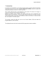
1 Introduction
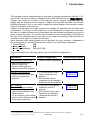
This software manual describes step by step how to operate successfully with the ½ 19"
and 19" MLT analyzer module and analyzer of the NGA 2000 Series from
.
Chapter two shows the structure of the software menus. Chapter three describes the
display and the keyboard of the analyzer. Chapter four describes the basic controls with
detailed illustrations. So you can easily compare the actual display of the analyzer module
with the illustrations of the manual.
Chapter five describes the expert controls and chapter six describes the technical level
configuration. The layout of both chapters is not as detailed as in chapter four. Normally,
the way to a certain software menu is described with the software catchwords, you have to
press to reach this menu. You will find the illustration of the corresponding LCD screen at
the end of the catchword listing. After that you can read the meaning of the functions and
variables of each expert or technical level menu.
Some contents of the expert controls are not important for every customer. It depends on
the configuration of your NGA 2000 system, relative to the following components:
♦ Control Module
CM
♦ Analyzer Module
AM
♦ Input/Output Modules
I/O's (SIO, DIO)
You can distinguish the following system units and SIO/DIO configurations:
System Unit
SIO/DIO-Configuration
CLD analyzer module (AM):1
• without front panel i.e.
without control unit
• can be combined with a
platform or an MLT analyzer
⇒
Platform (CM software):
• Control unit with front panel
• without measurement
channels
⇒
Local I/O's are not existing
1 SIO and up to 4 DIO's
can be installed in the
platform
⇒ SIO and DIO can be
configured for all channels
combined with the platform
MLT analyzer
⇒ 1 SIO and 1 DIO can be
(CM and MLT AM software):
installed in the MLT
analyzer
• Analyzer with front panel
⇒ SIO and DIO can be con• CM and AM software in the
figured for all channels
same analyzer,
combined with the MLT
i.e. all functions of the control
analyzer
unit and of the AM are united
in the same implement
1
Corresponding Chapter
∗ ⁄
∗ chapter 5.2
p. 29 to 44
∗ chapter 5.2
p. 29 to 44
The configuration of other analyzer modules like MLT modules is described in their own manuals !
90003749(1) [NGA-e (Software CLD 2.3/MLT 3.1.X)] 04/98
NGA 2000
1-1
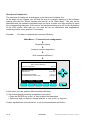
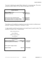
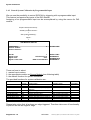
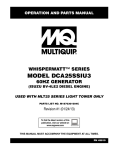
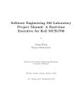
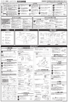
The following illustrations shall make plain the connection between the hardware configuration and the software setup of the modules:
NGA 2000 System via Platform
(see 5.1.17)
(see 5.1.18)
Analyzer
Modules (AM's)
SIO
Control
Module (CM)
Auxiliary
Modules
MLT
DIO
(other manuals)
CLD
(other manuals)
FID
(other manuals)
PMD
Platform
Local
I/O's
SIO
(see 5.2.1)
DIO
(see 5.2.2)
Other I/O´s
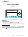
NGA 2000 System via MLT Analyzer
Analyzer
Modules (AM's)
(see 5.1/5.5)
(other manuals)
1-2
SIO
DIO
Control
Modul (CM)
CLD
MLT
(other manuals)
FID
(other manuals)
PMD
NGA 2000
MLT Analyzer
Local
I/O's
Auxiliary
Modules
SIO
(see 5.2.1)
DIO
(see 5.2.2)
90003749(1) [NGA-e (Software CLD 2.3/MLT 3.1.X)] 04/98
90003749(1) [NGA-e (Software CLD 2.3/MLT 3.1.X)] 04/98
NGA 2000
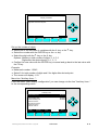
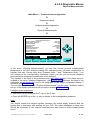
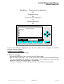
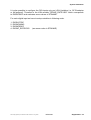
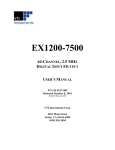
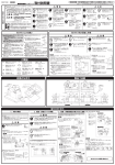
At each menu point of the "Expert controls" and "Technical level" you can find which functionality will be set up:
AM (Analyzer Module), CM ( Control Module), I/O ( Input-/Output Module).
Menu lines ending with three points (...) are followed by submenus with further functions and set-ups.
*
*
(AM, CM, I/O's:
SIO, DIO and other I/O's)
- Listing of all modules...
(Other I/O's)
- Other module
diagnostic menus...
(AM, CM, I/O's:
SIO, DIO and other I/O's)
- Diagnostic menus...
(AM, CM, I/O's:
SIO, DIO and other I/O's)
- Service menus...
(CM)
- System set up...
Technical level
configuration...
In the menu structure shown above, you will find the most important ramifications of the MLT software 3.1.X for the
MLT platform and analyzer versions. The menu points related to the CLD analyzer module are marked with "AM".
They belong to the CLD software revision number 2.3.
(CM)
- System calibration...
(Other I/O's)
- Auxiliary module set up...
(AM)
- Analyzer module set up...
(CM)
- System set up...
(I/O's: SIO, DIO)
- Auxiliary module
controls...
(AM)
- Expert analyzer
controls...
Expert controls
and set up...
*
Notes:
- Range set-up
- Range and
functional control
- Ozonator power
enable/disable
- Measurement mode
selection: NO/NOx
- Zeroing...
- Spanning...
Basic controls... (AM)
Main Menu
2 Structure of Menus
2-1
2-2
NGA 2000
90003749(1) [NGA-e (Software CLD 2.3/MLT 3.1.X] 04/98
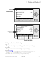
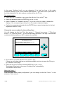
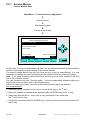
3 Display and Keyboard
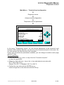
3.1 Starting and Initializing
After switching on the CLD analyzer module (in a platform or part of a NGA network), the
initialization procedure will be performed. A self control of the analyzer modules or the
analyzer(s) is running. You can see a sequence of several displays. They show the status
of initialization, revision notes of the MLT software and the
tag. At the end
of this procedure you can see the single component display of channel one. It is the origin
to all the other channels, menus and submenus.
The instructions of the basic controls (chapter four) are all beginning with the single component display. The actual display might differ from the shown one because the customer
can configure it according to his requirements.
TAG
here e.g.: CLD Analyzer Module
CLD
95.00
ppm NOx
Range: 4
0
250
Sample press.:
340 hPa
Detector temperature: 0.5 C
Block temperature:
51.5 C
360 C
Converter temp.:
DISPLAY
STATUS
F1
F2
MENU
F3
NEXT
F4
INFO
F5
Typical starting menu after switching on
3.2 Display and Function
The LCD-screen shows all measurement values of the analyzer and all customer instructions. You can operate with five function keys, four arrow keys (cursors) and the enter key.
The function of each key depends on:
♦ the type of analyzer/analyzer module used
♦ the optional auxiliary modules (e.g. I/O boards) used
♦ the individual menu displayed
In case of power failure all customer specific module parameters are saved by a batterypowered buffer.
90003749(1) [NGA-e (Software CLD 2.3/MLT 3.1.X)] 04/98
NGA 2000
3-1
3.3 Operating Keys
CLD
95.00
ppm NOx
Range: 4
0
250
Sample press.:
340 hPa
Detector temperature: 0.5 C
Block temperature:
51.5 C
Converter temp.:
360 C
DISPLAY
STATUS
F1
F2
MENU
F3
NEXT
F4
INFO
F5
Function Keys:
♦ Keys without defined functions
♦ The current function depends on
the menu selected
♦ The softkey legend is shown on
the display above the key
Cursor keys:
↑ -key / ↓ -key:
♦ Line up / line down
within the same menu
♦ Alteration of numbers,
variables or digits
← -key/ → -key:
♦ Moving back/forwards
between the pages of
a menu
♦ Selection of digits
Enter Key:
♦ To confirm a previously entered value
(variable)
♦ To start a selected function
(Alternative: → -key)
♦ To go into a menu (via menu line)
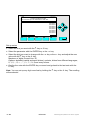
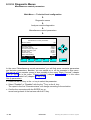
3.4 Lines
Lines can be selected by the ↓ -key or the ↑ -key. The selected line is displayed white on
black. You have four different types of lines in the menu:
Menu line...
♦ Line ending with three dots.
♦ You will go to a submenu by pressing the ENTER key or the → -key in such a line.
Function line !
♦ Line ending with an exclamation-mark.
♦ You will start a function (e.g. NO/NOx-toggle) by pressing the ENTER key or
the → -key in such a line.
Line of variables:
♦ Line ending with a colon.
♦ Display of module parameters (variables).
♦ Some parameters can be changed (e.g. range number), some parameters display only
a status (e.g. calibration status) and cannot be changed.
Text line
♦ Line without any punctuation marks.
♦ Only display of informations (e.g. analyzer module tag).
3-2
NGA 2000
90003749(1) [NGA-e (Software CLD 2.3/MLT 3.1.X)] 04/98
3 Display and Keyboard
Text Line
CLD
95.0 ppm
Basic Controls
Line of Variables
Measurement range number:
Range upper limit:
Range and functional control:
Ranges with valid calibration:
Calibration status:
If it won´t calibrate...
Status:
Measurement mode:
Ozonator status:
Ozonator power:
HOME
F1
NO/NOx
F2
ZERO
F3
4
250.0 ppm
LOCAL
4
READY
STANDBY
NOx
On
Enabled
SPAN
INFO
F4
F5
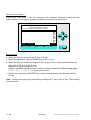
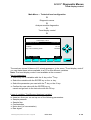
CLD
95.0 ppm
Zero/span calibration
Function Line
Menu Line
Measurement range number:
Zero gas concentration:
Span gas concentration:
Sample flow:
Raw measurement signal:
Measurement gas:
NO/NOx toggle!
Status:
Result...
Calibration adjustment limits:
HOME
F1
FACTORS
F2
ZERO
F3
3
0.0 ppm
100.0 ppm
1100 ml/min
521590
NOx
READY
Disabled
SPAN
F4
INFO
F5
Function Key Legend
3.5 Important Functions of the Softkeys
DISPLAY
♦ Change from the single component display to the multi component display.
MEASURE
♦ Change from the main menu to the single component display.
STATUS (see 3.7!)
♦ Change to the status report: Display of the most important parameters and
status informations of the CLD module or of the current channel.
♦ If available, this command is always assigned to the F2 key.
90003749(1) [NGA-e (Software CLD 2.3/MLT 3.1.X)] 04/98
NGA 2000
3-3
MENU
♦ Change from the single component display to the main menu or from several submenus
to higher menus.
ESCAPE or <<<
♦ Changing back to the last menu page selected.
♦ Reset of a changed but not confirmed parameter to the former value resp. to zero.
BACK
♦ Reset of a changed but not confirmed parameter to the former value.
LOCK
♦ Lock of any operation level, if activated. Each of the three operation levels has to be
activated separately.
♦ F4 key of the main menu.
NEXT
♦ Change of the channel in the same menu. This will only be possible, if several channels
of an analyzer or of combined analyzers are existing. Then, all available channels can
be selected one after another.
♦ In the main menu you can move among all channels of the connected analyzers and
analyzer modules. In the submenus you can only move among the channels of the
current analyzer or analyzer module.
INFO
♦ Change to menus containing status or help informations of the actual menu.
♦ If available, this function is always assigned to the F5 key.
3.6 Entering/Changing of Variables
ENTER Key
♦ If you will press this key in a line of variables, the parameter will be displayed white on
black and can be changed. After you will have set up a new value, you can confirm it by
pressing the ENTER key again.
↑ -key / ↓ -key
Function will depend on the variable selected: - Changing of the parameter values
- Scrolling among variables selected
- Changing of digits or characters
♦ Numbers consisting of several digits will increase/decrease totally, not digit by digit.
♦
← -key / → -key
♦ Selection of digits within a parameter.
♦ For some variables you can change the quantity of digits or characters.
3-4
NGA 2000
90003749(1) [NGA-e (Software CLD 2.3/MLT 3.1.X)] 04/98
3 Display and Keyboard
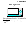
3.7 The STATUS Key
From the single component display or from the main menu you can change with the F2
key (STATUS) to the menu "Current measurement parameters":
CLD
95.0 ppm
Current measurement parameters
Analyzer gas measured:
Measurement range number:
Range change control:
NOx
3
LOCAL
Linearization mode:
Disabled
Analyzer operational state:
Analyzer alarm state:
Alarms reported:
HOME
F1
ESCAPE
F2
STANDBY
NORMAL
FAILURE
MORE
F3
INFO
F4
F5
CLD
95.0 ppm
Current measurement parameters
Response time:
Bypass flow:
Capillary pressure:
Detector temperature:
HOME
F1
3.0 s
1100 ml/min
340 hPa
0.5 C
ESCAPE
F2
MORE
F3
F4
INFO
F5
In the menu "Current measurement parameters" you can control the status of the CLD
analyzer module. With the F3 key (MORE) you can change to a further menu page of this
menu. With the F2 key (ESCAPE) you can always go back to the main menu. From the
second menu page you can return to the first with the F4 key (MORE) or the ← -key.
In the menu "Current measurement parameters" you will only find status informations. You
cannot change the setups there. If you want to modify some parameters, you have to
change to the menu "Basic Controls" (see chapter 4) or to the menu "Analyzer module set
up" (see chapter 5.1) resp. "Expert analyzer controls" (see chapter 5.5).
90003749(1) [NGA-e (Software CLD 2.3/MLT 3.1.X)] 04/98
NGA 2000
3-5
3-6
NGA 2000
90003749(1) [NGA-e (Software CLD 2.3/MLT 3.1.X)] 04/98
4 Basic Controls
In the chapter "Basic Controls" you will find the most important functions to set up your
CLD analyzer module via an NGA front panel:
1) Measurement p. 4 - 3pp (Chapter 4.1.1 and 4.1.2, p. 4-3 to 4-6, are only important
for systems with several channels.)
2) Calibration
p. 4 - 21pp
All steps are figured with detailed illustrations and operation instructions. In the left column
you can see display and keyboard of the NGA front panel. In the right column you can
read the instructions and notes. All instructions will begin with any single component
display and will end with the corresponding single component display after the setups are
done. The keys you have to press are illustrated in black. The instructions are completed
with notes and further informations.
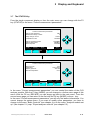
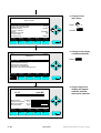
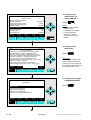
Example: You want to change from the single component display of NOx to the main menu
•
•
Picture one shows the starting situation: single component display of NOx.
If you press the F3 key you will change to menu page shown in picture 2: Main Menu.
Left column:
Right column:
LCD and keyboard
Instructions and notes
⇒ Change to the
Main Menu
CLD
95.00
ppm NOx
Range: 4
0
F3
250
Press
Sample press.:
340 hPa
Detector temperature: 0.5 C
Block temperature:
51.5 C
Converter temp.:
360 C
DISPLAY
STATUS
F1
F2
MENU
F3
or
NEXT
F4
CLD
INFO
F5
⇒ Next instruction
or step,
here e.g.:
Change to the
Basic Controls:
95.0 ppm
Main Menu
Basic controls...
Expert controls and set up...
(Operational configuration)
Technical level configuration...
(Diagnostic and manufacturing/service)
Press
MEASURE
STATUS
F1
F2
NEXT
F3
LOCK
F4
90003479(1) [NGA-e (Software CLD 2.3/MLT 3.1.X)] 04/98
INFO
F5
or
NGA 2000
4-1
4-2
NGA 2000
90003749(1) [NGA-e (Software CLD 2.3/MLT 3.1.X)] 04/98
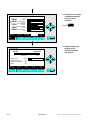
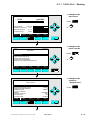
4.1.1 Measurement - Multi Component Display:
Change of Channel
⇒ Change to the multi
component display
CLD
95.00
ppm NOx
Range: 4
0
F1
Press
250
Note:
You can change to the
multi component display
from each single
component display.
Sample press.:
340 hPa
Detector temperature: 0.5 C
Block temperature:
51.5 C
Converter temp.:
360 C
DISPLAY
STATUS
F1
F2
MENU
F3
NEXT
F4
INFO
F5
⇒ Enable the selecting:
">"
CLD
95.00
45.00
333.0
150.0
20.00
CLD
ppm NOx
MLT25/CH1/R2
ppm CO
MLT25/CH2/R2
ppm SO2
MLT25/CH3/R2
ppm NO
MLT25/CH4/R2
%O2
SELECT
STATUS
TAGS OFF
F1
F2
F3
F1
Press
or
INFO
F4
F5
Note:
If no channels of other
analyzer modules are
combined to the CLD,
only the bargraph of the
CLD module will be displayed.
Then, a change of channel
will not be possible !
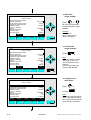
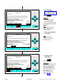
⇒ Select any channel
CLD
95.00
45.00
333.0
150.0
20.00
CLD
ppm NOx
MLT25/CH1/R2
ppm CO
MLT25/CH2/R2
ppm SO2
MLT25/CH3/R2
ppm NO
MLT25/CH4/R2
%O2
SELECT
STATUS
TAGS OFF
F1
F2
F3
90003749(1) [NGA-e (Software CLD 2.3/MLT 3.1.X)] 04/98
Press
or
as often as necessary to
put the > - mark into the
selected line.
INFO
F4
Example:
Change from
NOX (CLD) to
CO (MLT channel 1)
F5
NGA 2000
4-3
⇒ Change to the single
component display
of the channel
selected
CLD
95.00
45.00
333.0
150.0
20.00
CLD
ppm NOx
MLT25/CH1/R2
ppm CO
MLT25/CH2/R2
ppm SO2
MLT25/CH3/R2
ppm NO
MLT25/CH4/R2
%O2
SELECT
STATUS
TAGS OFF
F1
F2
F3
F1
Press
INFO
F4
F5
MLT25/CH1/R2
45.00
ppm CO
Range: 2
0
⇒ Single component
display of the
channel selected
will appear
250
Temperature:
25.0 C
Function Control:
No
Maintenance Request:
No
No
Failure:
DISPLAY
STATUS
F1
F2
4-4
MENU
F3
NEXT
F4
INFO
F5
NGA 2000
90003749(1) [NGA-e (Software CLD 2.3/MLT 3.1.X)] 04/98
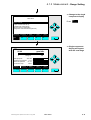
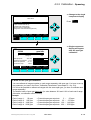
4.1.2 Measurement - Multi Component Display:
Sequence setup
⇒ Change to the multi
component display
CLD
95.00
ppm NOx
Range: 4
0
F1
Press
250
Sample press.:
340 hPa
Detector temperature: 0.5 C
Block temperature:
51.5 C
Converter temp.:
360 C
DISPLAY
STATUS
F1
F2
MENU
F3
NEXT
F4
INFO
F5
⇒ Enable the selecting:
">"
CLD
95.00
45.00
333.0
150.0
20.00
CLD
ppm NOx
MLT25/CH1/R2
ppm CO
MLT25/CH2/R2
ppm SO2
MLT25/CH3/R2
ppm NO
MLT25/CH4/R2
%O2
SELECT
STATUS
TAGS OFF
F1
F2
F3
F1
Press
or
INFO
F4
F5
⇒ Select the channel
for position one
CLD
95.00
45.00
333.0
150.0
20.00
Note:
If no channels of other
analyzer modules are
combined to the CLD,
only the bargraph of the
CLD module will be displayed.
Then, the sequence setup
will not be possible !
CLD
ppm NOx
MLT25/CH1/R2
ppm CO
MLT25/CH2/R2
ppm SO2
MLT25/CH3/R2
ppm NO
MLT25/CH4/R2
%O2
SELECT
STATUS
TAGS OFF
F1
F2
F3
90003749(1) [NGA-e (Software CLD 2.3/MLT 3.1.X)] 04/98
Press
or
as often as necessary to
put the > - mark into the
selected line.
INFO
F4
F5
NGA 2000
Example:
MLT channel 2 (SO2) shall
appear at position one of the
multi component display.
4-5
⇒ Assignation of the
channel selected to
position one
CLD
95.00
45.00
333.0
150.0
20.00
CLD
ppm NOx
MLT25/CH1/R2
ppm CO
MLT25/CH2/R2
ppm SO2
MLT25/CH3/R2
ppm NO
MLT25/CH4/R2
%O2
SELECT
STATUS
TAGS OFF
F1
F2
F3
Press
INFO
F4
F5
⇒ Multi component
display will appear
with the changed
sequence
MLT25/CH2/R2
MLT25/CH2/R2
ppm SO2
CLD
ppm NOx
MLT25/CH1/R2
ppm CO
MLT25/CH3/R2
ppm NO
MLT25/CH4/R2
%O2
333.0
95.00
45.00
150.0
20.00
SELECT
STATUS
TAGS OFF
F1
F2
F3
4-6
Note:
The channel selected will
appear at position one.
All the other channels will
automatically appear one
line below their last position.
Note:
Now, you can change
to any available single
component display.
The method is described in
the last chapter (4.1.1).
INFO
F4
F5
NGA 2000
90003749(1) [NGA-e (Software CLD 2.3/MLT 3.1.X)] 04/98
4.1.3 Measurement - Range Setting
⇒ Change to the
main menu
CLD
95.00
ppm NOx
Range: 4
0
F3
Press
250
Sample press.:
340 hPa
Detector temperature: 0.5 C
Block temperature:
51.5 C
Converter temp.:
360 C
DISPLAY
STATUS
F1
F2
MENU
F3
or
NEXT
F4
INFO
F5
95.0 ppm
CLD
⇒ Change to the
basic controls
Main Menu
Basic controls...
Press
Expert controls and set up...
(Operational configuration)
Technical level configuration...
(Diagnostic and manufacturing/service)
or
MEASURE
STATUS
F1
F2
NEXT
F3
LOCK
F4
CLD
INFO
F5
95.0 ppm
Basic Controls
Measurement range number:
Range upper limit:
Range and functional control:
Ranges with valid calibration:
Calibration status:
If it won´t calibrate...
Status:
Measurement mode:
Ozonator status:
Ozonator power:
HOME
F1
NO/NOx
F2
ZERO
F3
90003749(1) [NGA-e (Software CLD 2.3/MLT 3.1.X)] 04/98
4
250.0 ppm
LOCAL
4
READY
STANDBY
NOx
On
Enabled
SPAN
F4
⇒ Choose the
measurement
range number
Press
or
INFO
F5
NGA 2000
4-7
CLD
95.0 ppm
⇒ Select the
range number
Basic Controls
Measurement range number:
Range upper limit:
Range and functional control:
Ranges with valid calibration:
Calibration status:
If it won´t calibrate...
Status:
Measurement mode:
Ozonator status:
Ozonator power:
4
4
250.0 ppm
LOCAL
4
READY
STANDBY
NOx
On
Enabled
ESCAPE
F1
F2
F5
Example:
Change from
range 4 (250 ppm) to
range 3 (100 ppm)
95.0 ppm
⇒ Confirm the
range selected
INFO
F3
F4
CLD
or
Press
as often as necessary
to select another range
number.
Basic Controls
Measurement range number:
Range upper limit:
Range and functional control:
Ranges with valid calibration:
Calibration status:
If it won´t calibrate...
Status:
Measurement mode:
Ozonator status:
Ozonator power:
4
3
250.0 ppm
LOCAL
4
READY
STANDBY
NOx
On
Enabled
ESCAPE
F1
F2
INFO
F3
F4
CLD
Press
Note:
If you don't want to set the
new range number, you
can reactivate the former
selection:
Press F2 (ESCAPE) and
confirm it with ENTER.
F5
95.0 ppm
⇒ Change to the
main menu
Basic Controls
Measurement range number:
Range upper limit:
Range and functional control:
Ranges with valid calibration:
Calibration status:
If it won´t calibrate...
Status:
Measurement mode:
Ozonator status:
Ozonator power:
HOME
F1
4-8
NO/NOx
F2
ZERO
F3
3
250.0 ppm
LOCAL
4
READY
STANDBY
NOx
On
Enabled
SPAN
F4
INFO
F5
NGA 2000
Press
or
F1
2 times
Note:
The range upper limit (line 2)
of the range selected will be
set up automatically after the
range setting is confirmed.
90003749(1) [NGA-e (Software CLD 2.3/MLT 3.1.X)] 04/98
4.1.3 Measurement - Range Setting
CLD
95.0 ppm
⇒ Change to the single
component display
Main Menu
F1
Press
Basic controls...
Expert controls and set up...
(Operational configuration)
Technical level configuration...
(Diagnostic and manufacturing/service)
MEASURE
STATUS
F1
F2
NEXT
F3
LOCK
F4
INFO
F5
⇒ Single component
display will appear
with the new range
CLD
95.00
ppm NOx
Range: 3
0
100
Sample press.:
340 hPa
Detector temperature: 0.5 C
Block temperature:
51.5 C
360 C
Converter temp.:
DISPLAY
STATUS
F1
F2
MENU
F3
90003749(1) [NGA-e (Software CLD 2.3/MLT 3.1.X)] 04/98
NEXT
F4
INFO
F5
NGA 2000
4-9
4 - 10
NGA 2000
90003749(1) [NGA-e (Software CLD 2.3/MLT 3.1.X)] 04/98
4.1.4 Measurement - Range and Functional Control
⇒ Change to the
main menu
CLD
95.00
ppm NOx
Range: 4
0
F3
Press
250
Sample press.:
340 hPa
Detector temperature: 0.5 C
Block temperature:
51.5 C
Converter temp.:
360 C
DISPLAY
STATUS
F1
F2
MENU
F3
or
NEXT
F4
INFO
F5
95.0 ppm
CLD
⇒ Cahnge to the
basic controls
Main Menu
Basic controls...
Press
Expert controls and set up...
(Operational configuration)
Technical level configuration...
(Diagnostic and manufacturing/service)
or
MEASURE
STATUS
F1
F2
NEXT
F3
LOCK
F4
CLD
INFO
F5
95.0 ppm
Basic Controls
Measurement range number:
Range upper limit:
Range and functional control:
Ranges with valid calibration:
Calibration status:
If it won´t calibrate...
Status:
Measurement mode:
Ozonator status:
Ozonator power:
HOME
F1
NO/NOx
F2
ZERO
F3
90003749(1) [NGA-e (Software CLD 2.3/MLT 3.1.X)] 04/98
4
250.0 ppm
LOCAL
4
READY
STANDBY
NOx
On
Enabled
SPAN
F4
⇒ Change to the
line "Range and
functional control"
Press
or
as often as necessary
until the line "Range and
functional control" will
appear white on black.
INFO
F5
NGA 2000
4 - 11
CLD
95.0 ppm
⇒ Choose the
parameter
Basic Controls
Measurement range number:
Range upper limit:
Range and functional control:
Ranges with valid calibration:
Calibration status:
If it won´t calibrate...
Status:
Measurement mode:
Ozonator status:
Ozonator power:
HOME
F1
NO/NOx
F2
ZERO
F3
4
250.0 ppm
LOCAL
4
READY
STANDBY
NOx
On
Enabled
SPAN
F4
F5
Basic Controls
Measurement range number:
Range upper limit:
Range and functional control:
Ranges with valid calibration:
Calibration status:
If it won´t calibrate...
Status:
Measurement mode:
Ozonator status:
Ozonator power:
4
250.0 ppm
LOCAL
4
READY
STANDBY
NOx
On
Enabled
LOCAL
ESCAPE
F1
F2
or
INFO
95.0 ppm
CLD
Press
⇒ Set up the range
and functional
control you want
+ Pay attention to
the note at p. 4-14 !
or
Press
as often as necessary
to select the parameter
you want.
INFO
F3
F4
CLD
F5
Options:
LOCAL, AUTO, REMOTE
95.0 ppm
⇒ Confirm the
parameter selected
Basic Controls
Measurement range number:
Range upper limit:
Range and functional control:
Ranges with valid calibration:
Calibration status:
If it won´t calibrate...
Status:
Measurement mode:
Ozonator status:
Ozonator power:
4
250.0 ppm
AUTO
4
READY
STANDBY
NOx
On
Enabled
LOCAL
ESCAPE
F1
4 - 12
F2
INFO
F3
F4
Press
Note:
If you don't want to set the
new parameter, you can
reactivate the former
selection:
Press F2 (ESCAPE) and
confirm it with ENTER.
F5
NGA 2000
90003749(1) [NGA-e (Software CLD 2.3/MLT 3.1.X)] 04/98
4.1.4 Measurement - Range and Functional Control
CLD
95.0 ppm
⇒ Change to the
main menu
Basic Controls
Measurement range number:
Range upper limit:
Range and functional control:
Ranges with valid calibration:
Calibration status:
If it won´t calibrate...
Status:
Measurement mode:
Ozonator status:
Ozonator power:
HOME
F1
NO/NOx
F2
ZERO
F3
4
250.0 ppm
AUTO
4
READY
or
Press
F1
2 times
STANDBY
NOx
On
Enabled
SPAN
F4
INFO
F5
95.0 ppm
CLD
⇒ Change to the single
component display
Main Menu
F1
Press
Basic controls...
Expert controls and set up...
(Operational configuration)
Technical level configuration...
(Diagnostic and manufacturing/service)
MEASURE
STATUS
F1
F2
NEXT
F3
LOCK
F4
INFO
F5
⇒ Single component
display will appear
after the changing
of the range and
functional control
CLD
95.00
ppm NOx
Range: 4
0
250
Sample press.:
340 hPa
Detector temperature: 0.5 C
Block temperature:
51.5 C
Converter temp.:
360 C
DISPLAY
STATUS
F1
F2
MENU
F3
90003749(1) [NGA-e (Software CLD 2.3/MLT 3.1.X)] 04/98
NEXT
F4
INFO
F5
NGA 2000
4 - 13
⇒ Range and functional control – Options:
• LOCAL:
The platform will be controlled via the display.
• AUTO:
The range will be selected automatically ("auto range"). This
function will only be available with an I/O board with 3 alarms
(PIN 70 656 193), because the auto ranging parameters are
located on the I/O board (see its own manual)!
• REMOTE:
The range selection will be controlled by digital inputs, e.g. via
a DIO board or I/O board with 3 alarms.
4 - 14
NGA 2000
90003749(1) [NGA-e (Software CLD 2.3/MLT 3.1.X)] 04/98
4.1.5 Measurement - Enable/Disable Ozonator Power
⇒ Change to the
main menu
CLD
95.00
ppm NOx
Range: 4
0
F3
Press
250
Sample press.:
340 hPa
Detector temperature: 0.5 C
Block temperature:
51.5 C
Converter temp.:
360 C
DISPLAY
STATUS
F1
F2
MENU
F3
or
NEXT
F4
INFO
F5
95.0 ppm
CLD
⇒ Change to the
basic controls
Main Menu
Basic controls...
Press
Expert controls and set up...
(Operational configuration)
Technical level configuration...
(Diagnostic and manufacturing/service)
or
MEASURE
STATUS
F1
F2
NEXT
F3
LOCK
F4
CLD
INFO
F5
95.0 ppm
⇒ Change to the line
"Ozonator power"
Basic Controls
Measurement range number:
Range upper limit:
Range and functional control:
Ranges with valid calibration:
Calibration status:
If it won´t calibrate...
Status:
Measurement mode:
Ozonator status:
Ozonator power:
HOME
F1
NO/NOx
F2
ZERO
F3
90003749(1) [NGA-e (Software CLD 2.3/MLT 3.1.X)] 04/98
4
250.0 ppm
LOCAL
4
READY
STANDBY
NOx
On
Enabled
SPAN
F4
Press
or
as often as necessary
until the line "Ozonator
power" will appear white
on black.
INFO
F5
NGA 2000
4 - 15
CLD
95.0 ppm
⇒ Choose the
parameter
Basic Controls
Measurement range number:
Range upper limit:
Range and functional control:
Ranges with valid calibration:
Calibration status:
If it won´t calibrate...
Status:
Measurement mode:
Ozonator status:
Ozonator power:
HOME
F1
NO/NOx
F2
ZERO
F3
4
250.0 ppm
LOCAL
4
READY
STANDBY
NOx
On
Enabled
SPAN
F4
F5
Basic Controls
Measurement range number:
Range upper limit:
Range and functional control:
Ranges with valid calibration:
Calibration status:
If it won´t calibrate...
Status:
Measurement mode:
Ozonator status:
Ozonator power:
4
250.0 ppm
LOCAL
4
READY
STANDBY
NOx
On
Enabled
Enabled
ESCAPE
F1
F2
or
INFO
95.0 ppm
CLD
Press
⇒ Select the ozonator
power status you
want
Press
or
to select "Enabled" or
"Disabled".
INFO
F3
F4
F5
⇒ Confirm the setup
CLD
95.0 ppm
Basic Controls
Measurement range number:
Range upper limit:
Range and functional control:
Ranges with valid calibration:
Calibration status:
If it won´t calibrate...
Status:
Measurement mode:
Ozonator status:
Ozonator power:
4
250.0 ppm
LOCAL
4
READY
STANDBY
NOx
On
Disabled
Enabled
Enabled
ESCAPE
F1
4 - 16
F2
INFO
F3
F4
Press
Note:
If you don't want to confirm
the new selection, you
can reactivate the former
one:
Press F2 (ESCAPE) and
confirm it with ENTER.
F5
NGA 2000
90003749(1) [NGA-e (Software CLD 2.3/MLT 3.1.X)] 04/98
4.1.5 Measurement - Enable/Disable Ozonator Power
CLD
95.0 ppm
⇒ Change to the
main menu
Basic Controls
Measurement range number:
Range upper limit:
Range and functional control:
Ranges with valid calibration:
Calibration status:
If it won´t calibrate...
Status:
Measurement mode:
Ozonator status:
Ozonator power:
HOME
F1
NO/NOx
F2
ZERO
F3
4
250.0 ppm
LOCAL
4
READY
or
Press
F1
2 times
STANDBY
NOx
OFF - DISABLED
Disabled
SPAN
F4
INFO
F5
95.0 ppm
CLD
⇒ Change to the single
component display
Main Menu
F1
Press
Basic controls...
Expert controls and set up...
(Operational configuration)
Technical level configuration...
(Diagnostic and manufacturing/service)
MEASURE
STATUS
F1
F2
NEXT
F3
LOCK
F4
INFO
F5
⇒ Single component
display will appear
after the setup of
the ozonator power
status
CLD
95.00
ppm NOx
Range: 4
0
250
Sample press.:
340 hPa
Detector temperature: 0.5 C
Block temperature:
51.5 C
Converter temp.:
360 C
DISPLAY
STATUS
F1
F2
MENU
F3
90003749(1) [NGA-e (Software CLD 2.3/MLT 3.1.X)] 04/98
NEXT
F4
INFO
F5
NGA 2000
4 - 17
4 - 18
NGA 2000
90003749(1) [NGA-e (Software CLD 2.3/MLT 3.1.X)] 04/98
4.1.6 Measurement - Measurement Mode: NO ↔ NOx
⇒ Change to the
main menu
CLD
95.00
ppm NOx
Range: 4
0
F3
Press
250
Sample press.:
340 hPa
Detector temperature: 0.5 C
Block temperature:
51.5 C
Converter temp.:
360 C
DISPLAY
STATUS
F1
F2
MENU
F3
or
NEXT
F4
INFO
F5
95.0 ppm
CLD
⇒ Change to the
basic controls
Main Menu
Basic controls...
Press
Expert controls and set up...
(Operational configuration)
Technical level configuration...
(Diagnostic and manufacturing/service)
or
MEASURE
STATUS
F1
F2
NEXT
F3
LOCK
F4
INFO
F5
⇒ Select NO ↔ NOx
CLD
95.0 ppm
F2
Basic Controls
Measurement range number:
Range upper limit:
Range and functional control:
Ranges with valid calibration:
Calibration status:
If it won´t calibrate...
Status:
Measurement mode:
Ozonator status:
Ozonator power:
HOME
F1
NO/NOx
F2
ZERO
F3
90003749(1) [NGA-e (Software CLD 2.3/MLT 3.1.X)] 04/98
4
250.0 ppm
LOCAL
4
READY
STANDBY
NOx
On
Enabled
SPAN
F4
Press
to select the
measurement mode
you want.
The current selection will
be displayed in the line
"Measurement mode".
INFO
F5
NGA 2000
4 - 19
CLD
95.0 ppm
⇒ Change to the
main menu
Basic Controls
Measurement range number:
Range upper limit:
Range and functional control:
Ranges with valid calibration:
Calibration status:
If it won´t calibrate...
Status:
Measurement mode:
Ozonator status:
Ozonator power:
HOME
F1
NO/NOx
F2
ZERO
F3
4
250.0 ppm
LOCAL
4
READY
STANDBY
NO
On
Enabled
SPAN
F4
F1
2 times
INFO
F5
13.8 ppm
CLD
or
Press
⇒ Change to the single
component display
Main Menu
F1
Press
Basic controls...
Expert controls and set up...
(Operational configuration)
Technical level configuration...
(Diagnostic and manufacturing/service)
MEASURE
STATUS
F1
F2
NEXT
F3
LOCK
F4
INFO
F5
⇒ Single component
display will appear
with the measurement mode selected
CLD
13.75
ppm NO
Range: 4
0
250
Sample press.:
340 hPa
Detector temperature: 0.5 C
Block temperature:
51.5 C
Converter temp.:
360 C
DISPLAY
STATUS
F1
F2
4 - 20
MENU
F3
NEXT
F4
INFO
F5
NGA 2000
90003749(1) [NGA-e (Software CLD 2.3/MLT 3.1.X)] 04/98
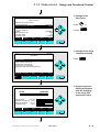
4.2.1 Calibration - Zeroing
⇒ Change to the
main menu
CLD
95.00
ppm NOx
Range: 4
0
F3
Press
250
Sample press.:
340 hPa
Detector temperature: 0.5 C
Block temperature:
51.5 C
Converter temp.:
360 C
DISPLAY
STATUS
F1
F2
MENU
F3
or
NEXT
F4
INFO
F5
95.0 ppm
CLD
⇒ Change to the
basic controls
Main Menu
Basic controls...
Press
Expert controls and set up...
(Operational configuration)
Technical level configuration...
(Diagnostic and manufacturing/service)
or
MEASURE
STATUS
F1
F2
NEXT
F3
LOCK
F4
CLD
INFO
F5
95.0 ppm
Basic Controls
Measurement range number:
Range upper limit:
Range and functional control:
Ranges with valid calibration:
Calibration status:
If it won´t calibrate...
Status:
Measurement mode:
Ozonator status:
Ozonator power:
HOME
F1
NO/NOx
F2
ZERO
F3
90003749(1) [NGA-e (Software CLD 2.3/MLT 3.1.X)] 04/98
4
250.0 ppm
LOCAL
4
READY
⇒ Change to the
submenu
"Analyzer zero"
F3
Press
STANDBY
NOx
On
Enabled
SPAN
F4
INFO
F5
NGA 2000
4 - 21
CLD
95.0 ppm
Analyzer zero
⇒ Start Zeroing
+ Pay attention to
the note at p. 4-23 !
Are you sure?
F3
You must have zero gas flowing through the analyzer.
Press
This control does NOT control any auto-calibration
module bound to this analyzer!
If you are sure, press ZERO again now.
Press the left arrow key when you are done.
Calibration status:
READY
Error message for last zero:
CAL OK
Caution:
You have to
• flow enough zero gas
through the analyzer
• look for a stabilized signal
before starting the zero gas
calibration.
Note:
You can go back to the
menu "Basic Controls"
with the F2 key.
HOME
F1
ESCAPE
F2
ZERO
F3
INFO
F4
F5
13.7 ppm
CLD
⇒ Zero gas calibration
is running
Analyzer zero
Are you sure?
You must have zero gas flowing through the analyzer.
This control does NOT control any auto-calibration
module bound to this analyzer!
If you are sure, press ZERO again now.
Press the left arrow key when you are done.
Calibration status:
ZEROING - WAIT
Error message for last zero:
CAL OK
Note:
You can abort the
procedure at any time
with the F2 key.
ABORT
F1
F2
F3
F4
CLD
F5
0.057 ppm
Analyzer zero
⇒ Change to the
main menu
Are you sure?
You must have zero gas flowing through the analyzer.
This control does NOT control any auto-calibration
module bound to this analyzer!
If you are sure, press ZERO again now.
Press the left arrow key when you are done.
Calibration status:
READY
Error message for last zero:
CAL OK
HOME
F1
4 - 22
ESCAPE
F2
ZERO
F3
INFO
F4
F5
NGA 2000
F1
Press
Alternative:
If you want to continue with
the span gas calibration
after the zeroing is done,
you can go back to the
basic controls with the F2
key or the ← -key.
(The spanning will be
described in the next
chapter: 4.2.2).
90003749(1) [NGA-e (Software CLD 2.3/MLT 3.1.X)] 04/98
4.2.1 Calibration - Zeroing
CLD
0.017 ppm
Main Menu
⇒ Change to the
single component
display
Basic controls...
F1
Press
Expert controls and set up...
(Operational configuration)
Technical level configuration...
(Diagnostic and manufacturing/service)
MEASURE
STATUS
F1
F2
NEXT
F3
LOCK
F4
INFO
F5
⇒ Single component
display will appear
after the zero gas
calibration
CLD
0.017
ppm NOx
Range: 4
0
250
Sample press.:
340 hPa
Detector temperature: 0.5 C
Block temperature:
51.5 C
360 C
Converter temp.:
DISPLAY
STATUS
F1
F2
MENU
F3
NEXT
F4
INFO
F5
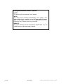
⇒ Notes for zero gas calibration:
• You can calibrate all ranges together or each range separately
with zero gas.
• You have to set up the parameter you want in the menu
"Calibration Parameters" (see chapter 5.1.2 S. 5-9).
90003749(1) [NGA-e (Software CLD 2.3/MLT 3.1.X)] 04/98
NGA 2000
4 - 23
4 - 24
NGA 2000
90003749(1) [NGA-e (Software CLD 2.3/MLT 3.1.X)] 04/98
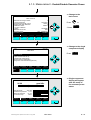
4.2.2 Calibration - Spanning
⇒ Change to the
main menu
CLD
95.00
ppm NOx
Range: 4
0
F3
Press
250
Sample press.:
340 hPa
Detector temperature: 0.5 C
Block temperature:
51.5 C
Converter temp.:
360 C
DISPLAY
STATUS
F1
F2
MENU
F3
or
NEXT
F4
INFO
F5
95.0 ppm
CLD
⇒ Change to the
basic controls
Main Menu
Basic controls...
Press
Expert controls and set up...
(Operational configuration)
Technical level configuration...
(Diagnostic and manufacturing/service)
or
MEASURE
STATUS
F1
F2
NEXT
F3
LOCK
F4
CLD
INFO
F5
95.0 ppm
Basic Controls
Measurement range number:
Range upper limit:
Range and functional control:
Ranges with valid calibration:
Calibration status:
If it won´t calibrate...
Status:
Measurement mode:
Ozonator status:
Ozonator power:
HOME
F1
NO/NOx
F2
ZERO
F3
90003749(1) [NGA-e (Software CLD 2.3/MLT 3.1.X)] 04/98
4
250.0 ppm
LOCAL
4
READY
⇒ Change to the
submenu
"Analyzer span"
F4
Press
STANDBY
NOx
On
Enabled
SPAN
F4
INFO
F5
NGA 2000
4 - 25
CLD
95.0 ppm
Analyzer span
⇒ Start Spanning
+ Pay attention to
the note at p. 4-27 !
Are you sure?
F4
You must have span gas flowing through the analyzer.
Press
This control does NOT control any auto-calibration
module bound to this analyzer!
If you are sure, press SPAN again now.
Press the left arrow key when you are done.
Calibration status:
READY
Error message for last span:
CAL OK
Caution:
You have to
• flow enough span gas
through the analyzer
• look for a stable signal
before starting the span gas
calibration.
Note:
You can go back to the
menu "Basic Controls"
with the F2 key.
HOME
F1
ESCAPE
F2
SPAN
F3
F4
INFO
F5
95.0 ppm
CLD
⇒ Span gas calibration
is running
Analyzer span
Are you sure?
You must have span gas flowing through the analyzer.
This control does NOT control any auto-calibration
module bound to this analyzer!
If you are sure, press SPAN again now.
Press the left arrow key when you are done.
Calibration status:
SPANNING - WAIT
Error message for last span:
CAL OK
Note:
You can abort the
procedure at any time
with the F2 key.
ABORT
F1
F2
F3
F4
CLD
F5
225.0 ppm
⇒ Change to the
main menu
Analyzer span
F1
Are you sure?
Press
You must have span gas flowing through the analyzer.
This control does NOT control any auto-calibration
module bound to this analyzer!
If you are sure, press SPAN again now.
Press the left arrow key when you are done.
Calibration status:
READY
Error message for last span:
CAL OK
HOME
F1
4 - 26
ESCAPE
F2
SPAN
F3
F4
INFO
Alternative:
If you want to continue with
further setups of the basic
controls, you can go back to
the corresponding menu with
the F2 key or the ← -key.
F5
NGA 2000
90003749(1) [NGA-e (Software CLD 2.3/MLT 3.1.X)] 04/98
4.2.2 Calibration - Spanning
CLD
225.0 ppm
⇒ Change to the single
component display
Main Menu
F1
Press
Basic controls...
Expert controls and set up...
(Operational configuration)
Technical level configuration...
(Diagnostic and manufacturing/service)
MEASURE
STATUS
F1
F2
NEXT
F3
LOCK
INFO
F4
F5
⇒ Single component
display will appear
after the span gas
calibration
CLD
225.00
ppm NOx
Range: 4
0
250
Sample press.:
340 hPa
Detector temperature: 0.5 C
Block temperature:
51.5 C
360 C
Converter temp.:
DISPLAY
STATUS
F1
F2
MENU
F3
NEXT
F4
INFO
F5
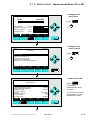
⇒ Notes for the span gas calibration:
• You can calibrate all ranges together or each range separately with span gas. You have to set up
the parameter you want in the menu "Calibration Parameters" (see chapter 5.1.2 p. 5-9).
• If it will not be possible to calibrate all ranges with the same span gas, you have to calibrate each
range separately!
• The desired value of span gas has to be (!) a value between 10% and 110% of each end of range.
Otherwise, no calibration will be running.
Example:
•
•
•
•
End of range 1:
50 ppm
End of range 2: 250 ppm
End of range 3: 1000 ppm
End of range 4: 2500 ppm
90003749(1) [NGA-e (Software CLD 2.3/MLT 3.1.X)] 04/98
→ Potential span gas setpoints:
5 –
55 ppm
→ Potential span gas setpoints:
25 – 275 ppm
→ Potential span gas setpoints: 100 – 1100 ppm
→ Potential span gas setpoints: 250 – 2750 ppm
NGA 2000
4 - 27
4 - 28
NGA 2000
90003749(1) [NGA-e (Software CLD 2.3/MLT 3.1.X)] 04/98
4.2.3 Calibration - If It Won´t Calibrate
⇒ Change to the
main menu
CLD
95.00
ppm NOx
Range: 4
0
F3
Press
250
Sample press.:
340 hPa
Detector temperature: 0.5 C
Block temperature:
51.5 C
Converter temp.:
360 C
DISPLAY
STATUS
F1
F2
MENU
F3
or
NEXT
F4
INFO
F5
95.0 ppm
CLD
⇒ Change to the
basic controls
Main Menu
Basic controls...
Press
Expert controls and set up...
(Operational configuration)
Technical level configuration...
(Diagnostic and manufacturing/service)
or
MEASURE
STATUS
F1
F2
NEXT
F3
LOCK
F4
CLD
INFO
F5
95.0 ppm
⇒ Change to the line
"If it won´t calibrate..."
Basic Controls
Measurement range number:
Range upper limit:
Range and functional control:
Ranges with valid calibration:
Calibration status:
If it won´t calibrate...
Status:
Measurement mode:
Ozonator status:
Ozonator power:
HOME
F1
NO/NOx
F2
ZERO
F3
90003749(1) [NGA-e (Software CLD 2.3/MLT 3.1.X)] 04/98
4
250.0 ppm
LOCAL
4
READY
STANDBY
NOx
On
Enabled
SPAN
F4
Press
or
as often as necessary
until the line "If it won´t
calibrate..." will appear
white on black.
INFO
F5
NGA 2000
4 - 29
CLD
95.0 ppm
Basic Controls
Measurement range number:
Range upper limit:
Range and functional control:
Ranges with valid calibration:
Calibration status:
If it won´t calibrate...
Status:
Measurement mode:
Ozonator status:
Ozonator power:
HOME
F1
NO/NOx
F2
ZERO
F3
4
250.0 ppm
LOCAL
4
READY
F4
CLD
F5
95.0 ppm
⇒ Change to the
main menu
INFO
If it won´t calibrate...
Check that you are flowing the correct gas, and the
gas concentration is what it is supposed to be.
Make sure that the reading is stable before starting.
If you have changed the range full scale value, or any
linearizer coefficients, or enabled or disabled it,
or done anything else that would affect how it
measures the gas, you may have made it hard for the
algorithm to get to a calibration.
In this case, manually adjust the coefficients
until the readings are close to correct, and try again.
HOME
F1
ESCAPE
F2
INFO
F3
F4
CLD
Press
Notes:
• Follow the instructions
on the screen
to calibrate succesfully!
• If you have further
questions, contact
your customer service,
please!
STANDBY
NOx
On
Enabled
SPAN
⇒ Change to the
menu page "If it
won´t calibrate..."
F1
Press
Alternative:
If you want to continue with
further setups of the basic
controls, you can go back to
the corresponding menu with
the F2 key or the ← -key.
F5
95.0 ppm
⇒ Change to the single
component display
Main Menu
F1
Press
Basic controls...
Expert controls and set up...
(Operational configuration)
Technical level configuration...
(Diagnostic and manufacturing/service)
MEASURE
STATUS
F1
F2
4 - 30
NEXT
F3
LOCK
F4
INFO
F5
NGA 2000
90003749(1) [NGA-e (Software CLD 2.3/MLT 3.1.X)] 04/98
4.2.3 Calibration - If It Won´t Calibrate
⇒ Single component
display will appear
CLD
95.00
ppm NOx
Range: 4
0
250
Sample press.:
340 hPa
Detector temperature: 0.5 C
Block temperature:
51.5 C
Converter temp.:
360 C
DISPLAY
STATUS
F1
F2
MENU
F3
90003749(1) [NGA-e (Software CLD 2.3/MLT 3.1.X)] 04/98
NEXT
F4
INFO
F5
NGA 2000
4 - 31
4 - 32
NGA 2000
90003749(1) [NGA-e (Software CLD 2.3/MLT 3.1.X)] 04/98
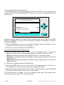
5
Expert Controls and Set up
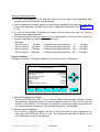
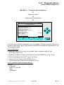
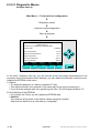
If you press the ENTER key or the → -key in the line "Expert controls and set up..." of the
"Main Menu" you will change to the following display:
CLD
95.0 ppm
Expert controls and set up
Expert analyzer controls...
Auxiliary module controls...
System set up...
Analyzer module set up...
Auxiliary module set up...
System calibration...
MAIN
F1
<<<
F2
NEXT
F3
INFO
F4
F5
From the menu "Expert controls and set up" you can change to several submenus to set
up parameters for the measurement and calibration of your analyzer and analyzer module.
Besides you can set up the configuration for auxiliary modules. Which part of these menus
are important for you depends on the configuration of your NGA 2000 system.
In the following table you will find a short overview about the contents of the menus and
where you will find the description in this manual:
Menu
Important Contents
Chapter in this manual
Expert analyzer
controls...
⇒
⇒
⇒
⇒
∗
5.5 p. 53 to 60
∗
5.2 p. 29 to 44
∗
5.4 p. 47 to 52
∗
5.1 p. 3 to 28
∗
5.3 p. 45
∗
See Supplement!
Auxiliary module
controls...
System set up...
Analyzer module set up...
⇒
⇒
⇒
⇒
⇒
⇒
Auxiliary module set up... ⇒
System calibration...
⇒
Zero/Span calibration
Range settings
Ozonator power
Configuration of the SIO and of
the DIO's installed in a platform
or in an MLT analyzer
Front panel control
Set up of the
single component display
Display resolution
Measurement/Calibration
parameters set up
Linearizer parameters set up
Sensor/Converter/Block
parameters set up and
optimization
Set up for micro processor
controlled auxiliary I/O modules
Zero gas and span gas
calibration of all channel
automatically
90003749(1) [NGA-e (Software CLD 2.3/MLT 3.1.X)] 04/98
NGA 2000
5-1
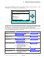
Structure of chapter five:
At the begin of any chapter you will find the way to a certain submenu of the MLT software
starting from the line "Expert controls and set up" in the "Main Menu". The way will be
described with the software catchwords that you have to enter one after another to reach
the corresponding submenu. At the end of the catchword listing you will find the illustration
of the LCD screen. After that you can read the set up instructions and explanations.
Sometimes the illustration will be completed by sketches or further menu pictures.
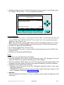
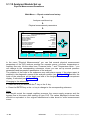
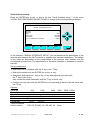
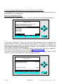
Example:
You want to set up the zero/span gas concentrations for all ranges of the
analyzer module.
Main Menu — Expert controls and set up
↓
Analyzer module set up
↓
Calibration gas list
↓
CLD
95.0 ppm
Calibration Gas List
Zero gas - range 1:
NO Span gas - range 1:
NOx Span gas - range 1:
0.00 ppm
2.00 ppm
2.00 ppm
Zero gas - range 2:
NO Span gas - range 2:
NOx Span gas - range 2:
0.00 ppm
25.00 ppm
25.00 ppm
Calibration...
HOME
F1
ESCAPE
F2
MORE
F3
INFO
F4
F5
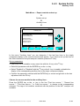
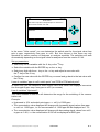
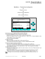
In the menu "Calibration Gas List" you can set up the desired zero and span gas values
for all ranges. On the first menu page you will find the parameters of range 1 and 2, on the
second page you will find the parameters of range 3 and 4. You can reach the second
menu page with the F3 key (MORE)...
Further explanations and instructions to set up the parameters will follow!
5-2
NGA 2000
90003749(1) [NGA-e (Software CLD 2.3/MLT 3.1.X)] 04/98
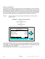
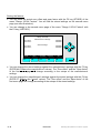
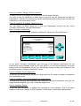
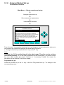
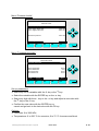
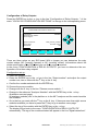
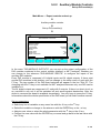
5.1
Analyzer Module Set up
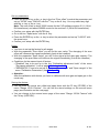
Main Menu — Expert controls and set up
↓
Analyzer module set up
↓
CLD
95.0 ppm
Analyzer module set up
Calibration gas list...
Calibration parameters...
Gas measurement parameters...
Analyzer parameter list...
Physical measurement parameters...
Displayed parameters...
Analyzer tag:
HOME
F1
CLD
ESCAPE
F2
INFO
F3
F4
F5
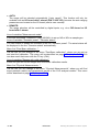
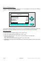
From the menu "Analyzer module set up" you can change to several submenus, where
you can set up the measurement and calibration parameters of the CLD analyzer module.
Besides, you can go to those submenus where you can set up the parameters of the
single component display.
Caution:
Normally, you will find "CLD" as analyzer module tag in the line "analyzer tag".
If the CLD module is part of an analyzer network: You have to change the configuration of the programmable digital inputs and analog outputs, if you change the
identification tag ! Because, the parameters of the module source will change ! So,
the relations will disappear !
Set up parameters:
♦ Select the menu line you want or the line of variables "Analyzer tag" with
the ↓ -key or the ↑ -key.
♦ Select the variable or change to the submenu with the ENTER key or the → -key.
♦ Select any digit with the ← -key or the → -key and adjust a new value with
the ↑ -key or the ↓ -key;
Maximum of digits: 30
Options: alphabet (capital and small letters), umlauts, letters from different languages,
0, 1, 2, ..., 9, +, -, *, /, =, ?, !, %, $ and many others.
♦ Confirm the new value with the ENTER key or cancel and go back to the last value with
the F2 key.
90003749(1) [NGA-e (Software CLD 2.3/MLT 3.1.X)] 04/98
NGA 2000
5-3
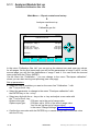
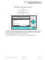
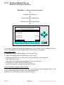
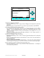
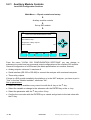
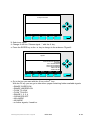
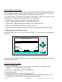
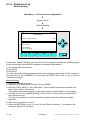
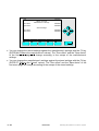
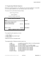
5.1.1 Analyzer Module Set up
Calibration/Calibration Gas List
Main Menu — Expert controls and set up
↓
Analyzer module set up
↓
Calibration gas list
↓
CLD
95.0 ppm
Calibration Gas List
Zero gas - range 1:
NO Span gas - range 1:
NOx Span gas - range 1:
0.00 ppm
2.00 ppm
2.00 ppm
Zero gas - range 2:
NO Span gas - range 2:
NOx Span gas - range 2:
0.00 ppm
25.00 ppm
25.00 ppm
Calibration...
HOME
F1
ESCAPE
F2
MORE
F3
INFO
F4
F5
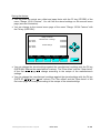
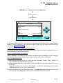
In the menu "Calibration Gas List" you can set up the desired zero and span gas values
for all ranges. On the first menu page you will find the parameters of range 1 and 2, on the
second page you will find the parameters of range 3 and 4. You can reach the second
menu page with the F3 key (MORE).
Via the menu line "Calibration..." you can change to the menu "Zero/span calibration",
where you can start zeroing and spanning (see next page).
Set up parameters:
♦ Select the line of variables you want or the menu line "Calibration..." with
the ↑ -key or the ↓ -key.
♦ Select the parameter or change to the menu "Zero/span calibration" with
the ENTER key or the → -key.
♦ Select any digit with the ← -key or the → -key and adjust a new value with
the ↑ -key or the ↓ -key.
Options zero gas:
0.00 ppm up to the end of range value
Options span gas:
0.00 ppm up to 120% of the end of range value
You can set up the end of range values
in the menu "Range Settings" (see 5.1.6 p. 5-16).
♦ Confirm the new value with the ENTER key or cancel and go back to the last value
with the F2 key.
5-4
NGA 2000
90003749(1) [NGA-e (Software CLD 2.3/MLT 3.1.X)] 04/98
Span gas calibration notes:
♦ The span gas setpoint of NO and NOx have to be the same value, because both
components will be calibrated simultaneously!
♦ You can calibrate all ranges together or each range separately with span gas. You have
to set up the parameter you want in the menu "Calibration Parameters" (see chapter 5.1.2
p. 5-9).
♦ If it will not be possible to calibrate all ranges with the same span gas, you have to
calibrate each range separately!
♦ The desired value of span gas has to be (!) a value between 10% and 110% of each end
of range. Otherwise, no calibration will be running:
•
Example:
End of range 1:
50 ppm
End of range 2: 250 ppm
End of range 3: 1000 ppm
End of range 4: 2500 ppm
→ Potential span gas setpoints:
5 –
55 ppm
→ Potential span gas setpoints: 25 – 275 ppm
→ Potential span gas setpoints: 100 – 1100 ppm
→ Potential span gas setpoints: 250 – 2750 ppm
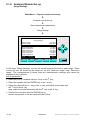
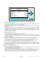
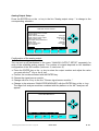
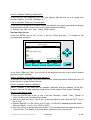
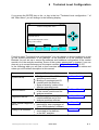
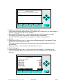
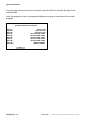
How to calibrate:
Change to the menu "Zero/span calibration" via the menu line "Calibration...":
CLD
95.0 ppm
Zero/span calibration
Measurement range number:
Zero gas concentration:
Span gas concentration:
Sample flow:
Raw measurement signal:
Measurement gas:
NO/NOx toggle!
Status:
Result...
Calibration adjustment limits:
HOME
F1
FACTORS
F2
ZERO
F3
3
0.0 ppm
100.0 ppm
1100 ml/min
521590
NOx
READY
Disabled
SPAN
F4
INFO
F5
1) Select the measurement range:
• Press the ENTER key or the → -key in the line "Measurement range number" to enter
the parameter. Select the range you want to calibrate with the ↑ -key or the ↓ -key and
confirm it with ENTER. The zero gas concentration and the span gas concentration of
the range selected will appear in the corresponding lines, automatically.
2) Select the gas component:
• Go to the line "NO/NOx toggle!" with the ↓ -key and select the gas component you
want with the ENTER key or the → -key. The component selected will appear in the
line "Measurement gas", automatically.
90003749(1) [NGA-e (Software CLD 2.3/MLT 3.1.X)] 04/98
NGA 2000
5-5
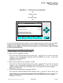
3) Zeroing:
• Change to the submenu "Analyzer zero" with the F3 key (ZERO).
• Pay attention to the notes on the screen !
• Flow enough zero gas through the CLD.
• Wait for a stable signal (look at the headline of the display). Then, start the zero gas
calibration with the F3 key (ZERO). The running procedure will be the same as it is
described detailed in chapter 4.2.1 of the basic controls (p. 4-22pp).
• Go back to the menu "Zero/span calibration" with the F2 key or the ← -key after the
zero gas calibration will be done (Messages on the display: READY/CAL OK).
4) Spanning:
• Change to the submenu "Analyzer span" with the F4 key (SPAN).
• Pay attention to the notes on the screen !
• Flow enough span gas through the CLD.
• Wait for a stable signal (look at the headline of the display). Then, start the span gas
calibration with the F4 key (SPAN). The running procedure will be the same as it is
described detailed in chapter 4.2.2 of the basic controls (p. 4-26pp).
• Go back to the menu "Zero/span calibration" with the F2 key or the ← -key after the
span gas calibration will be done (Messages on the display: READY/CAL OK).
Alternative: Go back to the "Main Menu" with the F1 key (HOME).
5) Check the calibration results:
• You can change to the submenu "Zero/span diagnostic data" via the line "Result..." of
the menu "Zero/span calibration". There you can control the results of the last zero
and span calibration. You can go back to the menu "Zero/span calibration" with the F2
key or the ← -key.
Manual input of calibration factors:
The calibration may be wrong because of a trouble in the gas flow. If a calibration was not
successful, you have to repeat it. It is possible that a new start of calibration will not solve
the problem, if the measured zero or span gas value will differ from normal signals largely.
In that case you have to put in the calibration factors manually:
♦ From the menu "Zero/span calibration" you can change to the submenu "Calibration
Factors" with the F2 key (FACTORS):
CLD
95.0 ppm
Calibration Factors
Only those factors appropriate for the current range
will affect the reading on the current range.
Make sure you are using the right ones!
Measurement range number:
3
Range 1 factors...
Range 2 factors...
Range 3 factors...
Range 4 factors...
HOME
F1
5-6
ESCAPE
F2
INFO
F3
F4
NGA 2000
F5
90003749(1) [NGA-e (Software CLD 2.3/MLT 3.1.X)] 04/98
♦ Select the range you want in the line "Measurement range number" and change via the
line "Range 1/2/3/4 factors..." to the corresponding submenu:
CLD
95.0 ppm
Range 3 Factors
Zero offset:
Span factor:
Full scale range at calibration:
Measurement range number:
521580.6
0.002608716
100.0 ppm
3
Raw measurement signal:
HOME
F1
STORE
F2
521660
NEXT
F3
HISTORY
F4
INFO
F5
Set up parameters:
♦ Press the ENTER key or the → -key in the line "Zero offset" to select the parameter and
♦
♦
♦
♦
set up "32700" resp. "524000" with the ↑ -key or the ↓ -key. You may select any digit
with the → -key or the ← -key.
Note: The zero offset is about 32000 counts for the CLD software revision 2.2.1 (16 bit
D/A transformer) and about 520000 counts for the revision 2.3 (20 bit D/A transformer).
Confirm your setup with the ENTER key.
Go to the line "Span factor" with the ↓ -key.
Press the ENTER key or the → -key to select the parameter and set up "0.00015" with
the arrow keys.
Confirm your setup with the ENTER key.
Notes:
♦ You have to set up the factors for all ranges.
♦ With the parameter "Zero offset" you will fix the zero value. The changing of the zero
offset will influence the signal immediately (look at the headline).
♦ With the parameter "Span factor" you will fix the signal at the span gas setpoint. The
changing of the span factor will influence the signal immediately (look at the headline).
♦ Conditions for the manual input of factors:
• "Disabled" has to be set up in the line "Calibration adjustment limits" of the menu
"Zero/span calibration".
• "SEPARATELY" has to be set up in the lines "Zero ranges" and "Span ranges" of the
menu "Calibration Parameters" (see 5.1.2, p. 5-9).
♦ Attention:
After the calibration with factors you have to calibrate with zero gas and span gas in the
usual way!
90003749(1) [NGA-e (Software CLD 2.3/MLT 3.1.X)] 04/98
NGA 2000
5-7
Saving the factors:
♦ You can store the actual zero offset and span factor with the F2 key (STORE) of the
menu "Range 1/2/3/4 Factors". You will find the stored settings on the second menu
page (see next illustration).
♦ You can change to the second menu page of the menu "Range 1/2/3/4 Factors" with
the F4 key (HISTORY):
CLD
95.0 ppm
Range 3 Factors
Manufacturer´s settings.
Zero offset:
Span factor:
0.000000
0.000000
Stored settings
Zero offset:
Span factor:
HOME
F1
0.000000
0.000000
NEXT
F2
RSTR MN
RSTR ST
F3
F4
INFO
F5
♦ You can change the stored settings against the manufacturer's settings with the F3 key
(RSTR MN: Restore the manufacturer's values). The "Zero offset" and the "Span factor"
of the first menu page will change according to the setups of the manufacturer's
settings.
♦ You can change the manufacturer's settings against the stored settings with the F4 key
(RSTR ST: Restore the "stored" values). The "Zero offset" and the "Span factor" of the
first menu page will change according to the setups of the stored settings.
5-8
NGA 2000
90003749(1) [NGA-e (Software CLD 2.3/MLT 3.1.X)] 04/98
5.1.2 Analyzer Module Set up
Calibration Parameters
Main Menu — Expert controls and set up
↓
Analyzer module set up
↓
Calibration parameters
↓
CLD
95.0 ppm
Calibration Parameters
Calibration adjustment limits:
Calibration averaging time:
Calibration failure alarm:
Cal. failure error allowed:
Disabled
5s
No
50 %
Calibration time out:
Zero ranges:
Span ranges:
HOME
F1
60 s
TOGETHER
SEPARATELY
ESCAPE
F2
INFO
F3
F4
F5
In the menu "Calibration Parameters" you can set up several parameters of the zero and
span calibration.
Set up parameters:
♦ Select the line of variables you want with the ↓ -key or the ↑ -key.
♦ Select the variable with the ENTER key or the → -key.
♦ Select any digit with the ← -key or the → -key and adjust a new value with
the ↑ -key or the ↓ -key
resp. select the whole parameter with the ↑ -key or the ↓ -key.
♦ Confirm the new value with the ENTER key or
cancel and go back to the last value with the F2 key.
Line of variables "Calibration adjustment limits:
♦ Enabled: The calibration result will only be accepted within the limit settings. If the
results will be out of these limits, you will find a corresponding error message in the
menu "Analyzer zero" respectively "Analyzer span". Illustrations of these menus you will
find in chapter 4.2.1 p. 4-22 resp. 4.2.2 p. 4-26.
♦ Disabled: The calibration will be possible, even if the calibration results will leave the
allowed limits. Compare with the explanations in chapter 5.1.1 p. 5-6/7.
90003749(1) [NGA-e (Software CLD 2.3/MLT 3.1.X)] 04/98
NGA 2000
5-9
Line of variables "Calibration averaging time":
The value in this line will determine the time range the analyzer will use to get the
calibration average. The precision will be better with longer times.
Options: 0 to 60 s; Standard: 5 s
Line of variables "Calibration failure alarm":
The accuracy of the signals may go down after a long use of the analyzer. If you will set
up "Yes" in the line "Calibration failure alarm", a warning message will display a wrong or
impossible calibration.
Line of variables "Cal. failure error allowed":
If the setpoint will differ more than allowed by the value in this line, a warning message
may be displayed. To enable this warning, "Yes" has to be set up in the line "Calibration
failure alarm".
Options: 5 to 80%; Standard: 50%
Line of variables "Calibration time out":
If the signal will not be stable after the time out set up in this line, a warning message may
be displayed. To enable this warning, "Yes" has to be set up in the line "Calibration failure
alarm".
Options: 0 to 300s; Standard: 60s
Lines of variables "Zero ranges/Span ranges":
♦ TOGETHER: All four ranges will be calibrated automatically one after another by zero
and span gas.
♦ SEPARATELY: Only the range selected will be calibrated by zero and span gas. You
have to set up this parameter, if you want to calibrate with manual factors (see chapter.
5.1.1 p. 5-6/7).
♦ Note: Only, if it is possible to get a span gas setpoint between 10% and 110% of each
end of range, you may calibrate all ranges together. Otherwise, only the ranges with
this condition will be calibrated automatically. The other ranges will be ignored!
5 - 10
NGA 2000
90003749(1) [NGA-e (Software CLD 2.3/MLT 3.1.X)] 04/98
5.1.3 Analyzer Module Set up
Gas Measurement Parameters
Main Menu — Expert controls and set up
↓
Analyzer module set up
↓
Gas measurement parameters
↓
CLD
95.0 ppm
Gas Measurement Parameters
Linearization parameters...
Response time / delay parameters...
Range setting...
Units...
Linearization functions...
HOME
F1
ESCAPE
F2
INFO
F3
F4
F5
From the menu "Gas Measurement Parameters" you can change to several submenus,
where you can set up parameters of ranges, of measurement units and of linearization:
♦ Select the line you want with the ↓ -key or the ↑ -key.
♦ Press the ENTER key or the → -key to change to the corresponding menu.
90003749(1) [NGA-e (Software CLD 2.3/MLT 3.1.X)] 04/98
NGA 2000
5 - 11
5.1.4 Analyzer Module Set up
Linearization Parameters
Main Menu — Expert controls and set up
↓
Analyzer module set up
↓
Gas measurement parameters
↓
Linearization parameters
↓
CLD
95.0 ppm
Linearization parameters
Range 1 linearizer:
If enabled, uses curve no.:
Range 2 linearizer:
If enabled, uses curve no.:
Range 3 linearizer:
If enabled, uses curve no.:
Range 4 linearizer:
If enabled, uses curve no.:
Disabled
1
Disabled
2
Disabled
3
Disabled
4
Set coefficients...
HOME
F1
ESCAPE
F2
INFO
F3
F4
F5
In the menu "Linearization parameters" you can enable the linearization for each range
and you can select the linearization curve.
Note:
Normally, the CLD is working linearly in the whole range. Therefore you do not have
to linearize generally ! If you will find deviations from the linearization, you should control
the ozone and sample gas supply. Optimize it, if necessary! Usually, the reason for
deviations will be a defect in the ozone supply.
Set up parameters:
♦ Select any line of variables or the menu line "Set coefficients..." with the ↓ -key
or the ↑ -key.
♦ Select the variable or change to the submenu "Linearity coefficients" with
the ENTER key or the → -key.
♦ Select the parameter you want with the ↑ -key or the ↓ -key.
♦ Confirm the new value with the ENTER key or
cancel and go back to the last value with the F2 key.
5 - 12
NGA 2000
90003749(1) [NGA-e (Software CLD 2.3/MLT 3.1.X)] 04/98
Lines of variables "Range 1/2/3/4 linearizer":
In these lines you can enable the linearization for the range selected.
You have to set up "Disabled" in these lines as long as you will determine the data for
linearization. This will be necessary to avoid interferences with existing values during the
calculation of the linearization curve.
Lines of variables "If enabled, uses curve no.":
You can select for each range one of the four linearization curves from the menu
"Linearity coefficients" (see next illustration).
Menu "Linearity coefficients":
You can change to the menu "Linearity coefficients" via the line "Set coefficients...":
CLD
95.0 ppm
Linearity coefficients
Curve 3
A0 coefficient:
A1 coefficient:
A2 coefficient:
A3 coefficient:
A4 coefficient:
Curve upper limit:
Curve over-range:
Curve under-range:
Status:
HOME
F1
0.000000
1.000000
0.000000
0.000000
0.000000
100.0 ppm
5.0 %
5.0 %
Disabled
ESCAPE
F2
NEXT
F3
LAST
F4
INFO
F5
In the menu "Linearity coefficients" you can put in the desired coefficients for the
linearization curve selected. With the F3 key (NEXT) you can scroll between the menu
pages of all four linearization curves. You will find the number of the curve selected in the
head line of each "Linearity coefficients" menu.
Line of variables "Curve upper limit":
In this line you should set up the end of range value for the range you want to determine
the linearization curve.
Lines of variables "Curve over-range/Curve under-range":
In these two lines you can determine how many per cent the linearization curve for the
range selected shall be over resp. under the range limits.
Line of variables "Status":
In this line you can enable or disable the linearization curve selected. This is the same
setup as in the lines "Range 1/2/3/4 linearizer" of the menu "Linearization parameters".
90003749(1) [NGA-e (Software CLD 2.3/MLT 3.1.X)] 04/98
NGA 2000
5 - 13
5.1.5 Analyzer Module Set up
Response Time/Delay Parameters
Main Menu — Expert controls and set up
↓
Analyzer module set up
↓
Gas measurement parameters
↓
Response time/delay parameters
↓
CLD
95.0 ppm
Response time/delay parameters
Range 1 t90 time:
Range 2 t90 time:
Range 3 t90 time:
Range 4 t90 time:
3.0 s
3.0 s
3.0 s
3.0 s
LON update rate:
10 per sec
Output delay time:
HOME
F1
0.0 s
ESCAPE
F2
INFO
F3
F4
F5
In the menu "Response time/delay parameters" you can set up the response time (t90
time) of the analyzer for each range and the output delay of the signal.
Set up parameters:
♦ Select any line of variables with the ↓ -key or the ↑ -key.
♦ Select the variable with the ENTER key or the → -key.
♦ Select any digit with the ← -key or the → -key and adjust a new value with
the ↑ -key or the ↓ -key
resp. select the whole parameter with the ↑ -key or the ↓ -key.
♦ Confirm the new value with the ENTER key or
cancel and go back to the last value with the F2 key.
Lines of variables "Range 1/2/3/4 t90 time":
The t90 time is defined as the time that has to run until the analyzer displays 90% of the
current concentration after a jump in the concentration level.
Options: 0 to 30 seconds for every range of a channel.
5 - 14
NGA 2000
90003749(1) [NGA-e (Software CLD 2.3/MLT 3.1.X)] 04/98
Line of variables "LON update rate":
In this line you can set up the update rate of the network variable.
Options: 1 per sec, 10 per sec, "ASAP" (As fast as possible)
Line of variable "Output delay time":
Example:
You can shift the absolute time of the
analog output signal for one channel. If
you use the right output delay time you
can watch the signals of several channels
at the same starting time.
Options: 0 to 30 seconds.
Conc.
CO
CO2
NO
Time
90003749(1) [NGA-e (Software CLD 2.3/MLT 3.1.X)] 04/98
NGA 2000
5 - 15
5.1.6 Analyzer Module Set up
Range Settings
Main Menu — Expert controls and set up
↓
Analyzer module set up
↓
Gas measurement parameters
↓
Range setting
↓
CLD
95.0 ppm
Range Settings
Minimum range:
Maximum range:
Range 1 lower limit:
Range 1 upper limit:
Range 2 lower limit:
Range 2 upper limit:
Range 3 lower limit:
Range 3 upper limit:
Range 4 lower limit:
Range 4 upper limit:
HOME
F1
10.0 ppm
10000 ppm
0.0 ppm
10.0 ppm
0.0 ppm
25.0 ppm
0.0 ppm
100.0 ppm
0.0 ppm
250.0 ppm
ESCAPE
F2
INFO
F3
F4
F5
In the menu "Range Settings" you can set up the begin and the end of each range. These
values will only be limited by the setups in the line "Minimum range" resp. "Maximum
range". The concentrations of these lines are manufacturer's settings and cannot be
changed by the customer.
Set up parameters:
♦ Select any line of variables with the ↓ -key or the ↑ -key.
♦ Select the variable with the ENTER key or the → -key.
♦ Select any digit with the ← -key or the → -key and adjust a new value with
the ↑ -key or the ↓ -key
resp. select the whole parameter with the ↑ -key or the ↓ -key.
♦ Confirm the new value with the ENTER key or
cancel and go back to the last value with the F2 key.
5 - 16
NGA 2000
90003749(1) [NGA-e (Software CLD 2.3/MLT 3.1.X)] 04/98
5.1.7 Analyzer Module Set up
Units
Main Menu — Expert controls and set up
↓
Analyzer module set up
↓
Gas measurement parameters
↓
Units
↓
CLD
95.0 ppm
Units
Gas measurement units:
ppm
Pressure measurement units:
hPa
Temperature measurement units:
C
ppm to mg/Nm3 conversion factor:
1.000
Variables are still sent as the basic SI unit.
HOME
F1
ESCAPE
F2
INFO
F3
F4
F5
In the menu "Units" you can set up the units of the analyzer for pressure, temperature and
gas concentration.
Set up parameters:
♦ Select any line of variables with the ↓ -key or the ↑ -key.
♦ Select the variable with the
8 -key or the → -key.
♦ Select any digit with the ← -key or the → -key and adjust a new value with
the ↑ -key or the ↓ -key
resp. select the whole parameter with the ↑ -key or the ↓ -key.
Options:
"Gas measurement units"
ppb, ppm, mg/Nm3, %
"Pressure measurement units"
hPa, psig
"Temperature measurement units"
C, F
"Conversion factor ppm – mg/Nm3"
0 to 100
♦ Confirm the new value with the ENTER key or
cancel and go back to the last value with the F2 key.
90003749(1) [NGA-e (Software CLD 2.3/MLT 3.1.X)] 04/98
NGA 2000
5 - 17
5.1.8 Analyzer Module Set up
Linearization Functions
Main Menu — Expert controls and set up
↓
Analyzer module set up
↓
Gas measurement parameters
↓
Linearization functions
↓
CLD
95.0 ppm
Linearization functions
Polynomial set up...
Midpoint correction set up...
Use the polynomial set up to generate a linearizing
polynomial from up to 20 gases. With more than 6 gases
it will produce a fourth order polynomial linearizer.
Use the midpoint correction for a piecewise-linear final
correction, to bring up to three points precisely onto
the curve.
HOME
F1
ESCAPE
F2
INFO
F3
F4
F5
From the menu "Linearization functions" you can change to several submenus, where you
can linearize the ranges and optimize the linearization functions:
♦ Change to the line you want with the ↓ -key or the ↑ -key.
Note:
Normally, the CLD is working linearly in the whole range. Therefore you do not have
to linearize generally ! If you will find deviations from the linearization, you should control
the ozone and sample gas supply. Optimize it, if necessary! Usually, the reason for
deviations will be a defect in the ozone supply.
Polynomial set up:
Press the ENTER key or the → -key in the line "Polynomial set up..." to change to the
corresponding menu:
5 - 18
NGA 2000
90003749(1) [NGA-e (Software CLD 2.3/MLT 3.1.X)] 04/98
CLD
95.0 ppm
Polynomial set up
Range to be linearized:
Current span gas:
Calculated polynomial order:
3
100.0 ppm
4
Gas values shown as:
Gas concentrations...
ppm
Analyzer function:
HOME
F1
ESCAPE
F2
READY
CALC
F3
INFO
F4
F5
1) Select the range to be linearized:
• Press the ENTER key or the → -key in the line "Range to be linearized" to select the
parameter.
• Select the range you want with the ↑ -key or the ↓ -key and confirm it with ENTER.
2) Zeroing and Spanning of the range selected:
• e.g.: Change to the "Main Menu" with the F1 key. Change after that via the line "Basic
controls..." to the corresponding menu. Press the F3 key(ZERO) resp. the F4 key
(SPAN) to start the calibration (Look at the descriptions in the chapters 4.2.1 p. 4-21
and 4.2.2 p. 4-26).
• Alternative: Change to the menu "Zero/span calibration" of the "Expert controls" to
start the calibration (see 5.1.1 p. 5-5).
3) Determine the display of gas concentration:
• Press the ENTER key or the → -key in the line "Gas values shown as" to select the
parameter.
• Select the concentration setup you want with the ↑ -key or the ↓ -key and confirm it
with the ENTER key:
• "ppm" for absolute concentrations
• "Percent of span gas" for relative concentrations, i.e. the gas value will be displayed
as percentage of the span gas. This will be necessary, if you will use diluted span gas.
4) How to get the x,y-values to determine the polynomial curve:
• Press the ENTER key or the → -key in the line "Gas concentrations...“ to change to
the corresponding submenu:
90003749(1) [NGA-e (Software CLD 2.3/MLT 3.1.X)] 04/98
NGA 2000
5 - 19
CLD
95.0 ppm
Gas value:
Raw reading:
Linearized value:
Gas concentrations
Point 1
-1.00
0.00 ppm
0.00 ppm
Point 2
Gas value:
Raw reading:
Linearized value:
-1.00
0.00 ppm
0.00 ppm
Point to be measured:
Analyzer function:
HOME
F1
ESCAPE
F2
Point 1
READY
DATA
F3
NEXT
F4
INFO
F5
♦ Input of the desired values:
•
You will need minimum 6 values to calculate a polynomial curve. In the menu "Gas
concentration" are maximum 20 values available.
• Press the ENTER key or the → -key in the line "Gas value" of "Point 1" to select the
parameter.
• Set up the concentration you want with the ↑ -key or the ↓ -key. If necessary, change
the sign with the F4 key ("+/-"). Confirm your input with the ENTER key. It is also
possible to select the digits with the ← -key or the → -key and to change the number
with the ↑ -key or the ↓ -key.
♦ Measuring of the raw values:
•
•
Flow the analyzer with a defined gas concentration.
After the signal will be stable press the F3 key (DATA): The analyzer will store the
desired value and the corresponding raw value as "Point 1" to calculate the
linearization polynom.
♦ Repeat the procedure described to get all values you need to calculate the polynom:
•
•
•
Go to the line "Gas value" of "Point 2" with the ↓ -key and set up the desired value.
Go to the line "Point to be measured" with the ↓ -key and select "Point 2".
Measure the corresponding raw value, store the values with the F3 key and so on...
♦ To set up the values of point 3, 4 and all the other points you have to change to further
menu pages with the F4 key (NEXT). You can always go back to the last menu page
with the F2 key (ESCAPE).
5) Calculation of the polynomial function:
• You can calculate the linearization polynom in the following way, after you will be
ready with the registration of the points:
• Go back to the menu "Polynomial set up" with the F2 key (ESCAPE) or the ← -key.
Then, press the F3 key (CALC): The analyzer will calculate the polynom with the
available points and store the coefficients of this function for the range selected.
5 - 20
NGA 2000
90003749(1) [NGA-e (Software CLD 2.3/MLT 3.1.X)] 04/98
6) Correction of the linearization polynom, if necessary:
• You can optimize the calculated linearization with maximum three additional points.
• Press the ENTER key or the → -key in the line "Midpoint correction set up..." of the
menu "Linearization functions" to change to the corresponding submenu:
CLD
95.0 ppm
Midpoint correction set up
Range 3
Correction:
Point being measured:
Point 1 gas concentration:
Point 2 gas concentration:
Point 3 gas concentration:
Point 1 reading:
Point 2 reading:
Point 3 reading:
Span gas value:
Analyzer functioning:
HOME
F1
ESCAPE
F2
SET
F3
RANGE 4
F4
DISABLED
Point 3
-1.00 ppm
-1.00 ppm
-1.00 ppm
-1.00 ppm
-1.00 ppm
-1.00 ppm
0.00 ppm
READY
INFO
F5
a) Range selecting:
• Range 1 will be selected automatically after entering the menu. If you want to select
another range to correct, press the F4 key (RANGE 2/3/4). The range selected will be
displayed in the headline of the menu.
b) Disable the correction:
• You have to disable the correction mode before calculating the correction data.
Otherwise, you will have interferences during the calculation with existing values.
• Press the ENTER key or the → -key in the line "Correction" to select the parameter.
Set up "DISABLED" with the ↑ -key or the ↓ -key and confirm it with the ENTER key.
c) Measured point selecting:
• Go to the line "Point being measured" with the ↓ -key.
• Press the ENTER key or the → -key to select the parameter. Select "Point 1" with the
the ↑ -key or the ↓ -key and confirm it with the ENTER key.
d) Set up the gas concentration for point 1:
• Go to the line "Point 1 gas concentration" with the ↓ -key.
• Press the ENTER key or the → -key to select the parameter.
• Select any digit with the ← -key or → -key and set up the value you want with the the
↑ -key or the ↓ -key. If necessary, change the sign with the F4 key ("+/-").
• Confirm your set up with the ENTER key.
e) Measuring of the gas concentrations:
• Flow the analyzer with the gas concentration set up of the line "Point 1 gas
concentration" and measure the raw value.
• After the signal will be stable press the F3 key (SET): The current signal will be
displayed in the line "Point 1 reading". But, the analyzer will equate the raw value with
the desired value of this point automatically.
90003749(1) [NGA-e (Software CLD 2.3/MLT 3.1.X)] 04/98
NGA 2000
5 - 21
f) Set up further correction points:
• You can repeat the steps c) to e) to determine maximum two further correction points.
• Select "Point 2" resp. "Point 3" in the line "Point being measured". Set up the value
you want in the line "Point 2 gas concentration" resp. "Point 3 gas concentration".
Measure the gas concentrations and set up the correction with the F3 key.
g) Enable the correction:
• Select "ENABLED" in the line "Correction": The midpoint correction will be done automatically for the range selected with the determined values.
The midpoint correction can be done for each range of the CLD analyzer module.
5 - 22
NGA 2000
90003749(1) [NGA-e (Software CLD 2.3/MLT 3.1.X)] 04/98
5.1.9 Analyzer Module Set up
Analyzer Parameter List
Main Menu — Expert controls and set up
↓
Analyzer module set up
↓
Analyzer Parameter List
↓
CLD
95.0 ppm
Analyzer Parameter List
Analyzer tag:
CLD
Ozonator status:
Ozonator power:
First line´s parameter:
Second line´s parameter:
Third line´s parameter:
Fourth line´s parameter:
OFF - PRESSURE
Enabled
Sample press.:
Detector temperature:
Block temperature:
Converter temp.:
Linearizer parameters...
HOME
F1
ESCAPE
F2
NEXT
F3
LAST
F4
INFO
F5
In the menu "Analyzer Parameter List" you can set up parameters of the single component
display, of the ozonator and the analyzer tag. You can also change to several submenus,
where you can set up linearizer parameters, concentration and calibration parameters.
Set up parameters:
♦ Select any line of variables or the menu line "Linearizer parameters..." with
the ↓ -key or the ↑ -key.
♦ Select the variable or change to the submenu "Linearity coefficients" with
the ENTER key or the → -key.
♦ Select any digit with the ← -key or the → -key and adjust a new value with
the ↑ -key or the ↓ -key
resp. select the whole parameter with the ↑ -key or the ↓ -key.
♦ Confirm the new value with the ENTER key or
cancel and go back to the last value with the F2 key.
Line of variables "Analyzer tag":
You can input a tag of maximum thirty digits. You will find the same line in the menu
"Analyzer module set up" (see chapter 5.1 p. 5-3).
Caution:
Normally, you will find "CLD" as analyzer module tag in the line "analyzer tag".
If the CLD module is part of an analyzer network: You have to change the configuration of the programmable digital inputs and analog outputs, if you change the
identification tag ! Because, the parameters of the module source will change ! So,
the relations will disappear !
90003749(1) [NGA-e (Software CLD 2.3/MLT 3.1.X)] 04/98
NGA 2000
5 - 23
Line of variables "Ozonator power":
Options: Enabled/Disabled
The setup of this line will change the displayed message of the line "Ozonator status".
That line is not available. The ozonator power setup is also possible in the menu "Basic
Controls" (see chapter 4.1.5 p. 4-15).
Lines of variables "First/Second/Third/Fourth line's parameter:
In these lines you can set up which of the following parameters shall be displayed in each
of the last four lines of the single component display:
♦
♦
♦
♦
♦
♦
♦
♦
♦
♦
♦
♦
♦
♦
♦
♦
♦
♦
Sample pressure (bargraph with measured value)
Sample flow (bargraph with measured value)
Raw signal (bargraph with measured value)
Validity (report: valid/invalid)
Interference (report: On/Off)
Health (report: Normal/...)
Operational state (report: STANDBY/...)
Measurement mode (report: 1/...)
Linearizer (report: Enabled/Disabled)
Calibration status (report: READY/...)
Output delay time (bargraph with value selected)
t90 time (bargraph with value selected)
Noise level (of concentration)
NO/NOx (Display: NO/NOx)
Detector temperature (bargraph with measured value)
Block temperature (bargraph with measured value)
Converter temperature (bargraph with measured value)
Ozonator (report: OFF - ENABLED/OFF - DISABLED)
Menu line "Linearizer parameters...":
Via this line you can change to the submenu "Linearity coefficients", where you can set up
the coefficients of the linearization curves manual. You can also reach the menu "Linearity
coefficients" via the menu "Linearization parameters". These menus are described
detailed in chapter 5.1.4 p. 5-12/13.
Ramifications via function keys:
With the F3 key (NEXT) of the menu "Analyzer Parameter List" you can change to further
menu pages, where you can set up the following concentration and calibration parameters:
♦
♦
♦
♦
♦
♦
Control mode
Output delay time
Begin and end of all four ranges
t90 time (response time) for all ranges
Linearizer enabling/disabling for each range
Calibration averaging time
5 - 24
NGA 2000
90003749(1) [NGA-e (Software CLD 2.3/MLT 3.1.X)] 04/98
♦
♦
♦
♦
♦
♦
♦
Calibration failure alarm
Calibration failure error allowed
Calibration time out
Zero and span gas calibration of the ranges together or separately
Enabling/Disabling of the calibration adjustment limits
Set up of the zero gas concentration of each range
Set up of the NO and NOx span gas concentration of each range
You can also set up all these parameters in the menus "Calibration Gas List", "Calibration
Parameters", "Response time/delay parameters" and "Range Settings". You can find the
descriptions of these menus in the chapters 5.1.1 p. 5-4, 5.1.2 p. 5-9/10 and 5.1.5/6 p. 5-14
to 16.
With the F4 key (LAST) of the menu "Analyzer Parameter List" you can change to the
menu page "Calibration Gases", where you can set up the NO and NOx span gas
concentrations of each range. This menu page is the same page you will reach by
pressing the F3 key (NEXT) several times.
90003749(1) [NGA-e (Software CLD 2.3/MLT 3.1.X)] 04/98
NGA 2000
5 - 25
5.1.10 Analyzer Module Set up
Physical Measurement Parameters
Main Menu — Expert controls and set up
↓
Analyzer module set up
↓
Physical measurement parameters
↓
CLD
95.0 ppm
Physical Measurements
Sample capillary pressure:
Ozone supply pressure:
Ozonator status:
Ozonator power:
Bypass flow:
Converter temperature:
Sensor temperature:
Block temperature:
Capillary flow rate:
Pressure limits...
Temperature limits...
HOME
F1
ESCAPE
F2
340 hPa
1030 hPa
ON
Enabled
1100 ml/min
360 C
0.5 C
51.5 C
200 ml/min
HISTORY
F3
F4
INFO
F5
In the menu "Physical Measurements" you can find several physical measurement
parameters of the CLD analyzer module like ozonator power, converter temperature or
capillary flow rate. Via the menu lines "Pressure limits..." and "Temperature limits..." you
can change to the corresponding submenus, where you can set up several pressure
parameters and temperature parameters of the analyzer.
The violation of the limits in the submenus may start alarm reports, if the alarm report is
enabled in the diagnostic menus of the analyzer module (see 6.3.2 p. 6-27). Besides, the
limits of the submenus will be begin and end of the bargraphs in the single component
display, if activated (see 5.1.9 p. 5-24).
Changing to the submenus:
♦ Select the line you want with the ↑ -key or the ↓ -key.
♦ Press the ENTER key or the → -key to change to the corresponding submenu.
Note:
You should control the sample capillary pressure, the ozone supply pressure and the
bypass flow in this menu after starting up your CLD. The values displayed in these lines
should be equivalent to the original manufacturer's data sheet to avoid measurement
errors.
5 - 26
NGA 2000
90003749(1) [NGA-e (Software CLD 2.3/MLT 3.1.X)] 04/98
Menu "Pressure Limits":
CLD
95.0 ppm
Pressure Limits
Sample capillary upper limit:
Sample capillary lower limit:
Ozone supply upper limit:
Ozone supply lower limit:
490.0 hPa
50.0 hPa
1050 hPa
700.0 hPa
Barometric pressure:
1013 hPa
HOME
F1
ESCAPE
F2
INFO
F3
F4
F5
Menu "Temperature Limits":
CLD
95.0 ppm
Temperature limits
Converter upper limit:
Converter lower limit:
500.0 C
150.0 C
Sensor upper limit:
Sensor lower limit:
Block upper limit:
Block lower limit:
HOME
F1
50.0 C
0.0 C
55.0 C
45.0 C
ESCAPE
F2
INFO
F3
F4
F5
Set up parameters:
♦ Select any line of variables with the ↓ -key or the ↑ -key.
♦ Select the variable with the ENTER key or the → -key.
♦ Select any digit with the ← -key or the → -key and adjust a new value with
the ↑ -key or the ↓ -key.
♦ Confirm the new value with the ENTER key or
cancel and go back to the last value with the F2 key.
Options:
♦ Pressures: 0 to 3000 hPa
♦ Temperatures: 0 to 500 °C for converter; 0 to 75 °C for sensor and block
90003749(1) [NGA-e (Software CLD 2.3/MLT 3.1.X)] 04/98
NGA 2000
5 - 27
5.1.11 Analyzer Module Set up
Displayed Parameters
Main Menu — Expert controls and set up
↓
Analyzer module set up
↓
Displayed parameters
↓
CLD
95.0 ppm
Displayed parameters
First line´s parameter:
Second line´s parameter:
Third line´s parameter:
Fourth line´s parameter:
Sample press.:
Detektor temperature:
Block temperature:
Converter temp.:
May be displayed on the appropriate
line of the single analyzer display screen.
HOME
F1
ESCAPE
F2
INFO
F3
F4
F5
In the menu "Displayed Parameters" you can determine which parameters shall be
displayed in the last four lines of the single component display. These are the same
parameters you can set up in the menu "Analyzer Parameter List" (see 5.1.9 p. 5-23).
Set up parameters:
♦ Select any line of variables with the ↓ -key or the ↑ -key.
♦ Select the variable with the ENTER key or the → -key.
♦ Select the parameter you want with the ↑ -key or the ↓ -key.
♦ Confirm the new value with the ENTER key or
cancel and go back to the last value with the F2 key.
5 - 28
NGA 2000
90003749(1) [NGA-e (Software CLD 2.3/MLT 3.1.X)] 04/98
5.2
Auxiliary Module Controls
Main Menu — Expert controls and set up
↓
Auxiliary module controls
↓
CLD
95.0 ppm
Auxiliary module controls
Set-up SIO module...
Set-up DIO module(s)...
MAIN
F1
BACK
F2
>>>
F3
<<<
F4
INFO
F5
From the menu "Auxiliary module controls" you can change to some submenus where you
can set up the parameters for the SIO module and the DIO modules of the MLT analyzer
or platform:
♦ Press the ENTER key or the → -key in the line "Set-up SIO module..." or in the line
"Set-up DIO module(s)..." to change to the corresponding submenus.
90003749(1) [NGA-e (Software CLD 2.3/MLT 3.1.X)] 04/98
NGA 2000
5 - 29
5.2.1 Auxiliary Module Controls
Local SIO Configuration Sections
Main Menu — Expert controls and set up
↓
Auxiliary module controls
↓
Set-up SIO module
↓
CLD
95.0 ppm
- LOCAL SIO CONFIGURATION SECTIONS Analog output setup...
Serial interface setup...
Configuration of Relay Outputs...
Module installed:
Yes
EXPERT
F1
INFO
F2
F3
F4
F5
From the menu "LOCAL SIO CONFIGURATION SECTIONS" you can change to
submenus to control and set up several output configurations of the auxiliary SIO module.
General Configuration of a SIO board (the whole specification is in another manual):
♦ Analog outputs: minimum 2, maximum 8
♦ Serial interface (RS 232 or RS 485) to connect the analyzer with a external computer
♦ Three relay outputs
If there is a SIO module installed in the platform or in the MLT analyzer, you have to put in
"Yes" in the line "Module installed", otherwise "No".
Set up parameters:
♦ Select the line of variables or any menu line with the ↓ -key or the ↑ -key.
♦ Select the variable or change to the submenu with the ENTER key or the → -key.
♦ Select the parameter with the ↑ -key or the ↓ -key.
♦ Confirm the new value with the ENTER key or cancel and go back to the last value with
the F2 key.
5 - 30
NGA 2000
90003749(1) [NGA-e (Software CLD 2.3/MLT 3.1.X)] 04/98
Analog Output Setup:
Press the ENTER key or the → -key in the line "Analog output setup..." to change to the
corresponding submenu:
CLD
95.0 ppm
- ANALOG OUTPUT SETUP Output number:
Choose signal source module...
Choose signal...
Signal value for 0% output:
Signal value for 100% output:
Output current range:
Hold output during calibration?
Signal name:
Current signal value:
Source module:
EXPERT
F1
1
0.00 ppm
2500.00 ppm
0...20 mA
No
NO/NOx
95.00 ppm
CLD
ADJUST
F2
F3
F4
INFO
F5
Configuration of the analog output:
1) Select the analog output number:
You can set up all parameters in the menu "ANALOG OUTPUT SETUP" separately for
each of the available analog outputs. The number of outputs depends on the hardware
configuration of the SIO module (minimum: 2, maximum: 8).
♦ Press the ENTER key or the → -key to select the output number and adjust the value
you want with the ↑ -key or the ↓ -key.
♦ Confirm the number selected with the ENTER key.
2) Choose the signal source module:
♦ Change with the ↓ -key to the line "Choose signal source module..."
♦ Change to the submenu "ANALYZER MODULES" with the ENTER key or the → -key.
The tags of all analyzer modules combined with the platform or the MLT analyzer will
appear:
CLD
95.0 ppm
- ANALYZER MODULES -
CLD
MENU
F1
BACK
F2
90003749(1) [NGA-e (Software CLD 2.3/MLT 3.1.X)] 04/98
>>>
F3
<<<
F4
NGA 2000
F5
5 - 31
♦ Go to the line you want with the ↑ -key or the ↓ -key.
♦ Select the tag of the channel with the ENTER key or the → -key:
The display will go back to the menu "ANALOG OUTPUT SETUP" automatically.
The tag of the channel selected will appear in the line "Source module".
3) Select any signal:
♦ Change to the line "Choose signal" with the ↓ -key.
♦ Press the ENTER key or the → -key to change to the submenu "SIGNALS":
95.0 ppm
CLD
- SIGNALS -
Sample flow:
Sample press.:
Ozonator:
Converter temp.:
Block temperature:
Detector temperature:
NO/NOx:
Noise level:
MENU
F1
BACK
F2
>>>
F3
<<<
F4
INFO
F5
♦ Change to the line you want with the ↑ -key or the ↓ -key.
You can change with the F3 key (>>>) to further menu pages containing other available
signals:
• t90 time
• Output delay time
• Calibration status
• Linearizer
• Measurement mode
• Operational state
• Health
• Interference
• Validity
• Raw signal
• Primary Variable
♦ Press the ENTER key or the → -key to select the signal:
The display will go back to the menu "ANALOG OUTPUT SETUP" automatically.
The signal selected will appear in the line "Signal name".
4) Determination of the output signal values:
You can determine the signal value for the 0% output and the 100% output in the lines
"Signal value for 0% output" or "Signal value for 100% output". So you have the possibility
to zoom out a certain part of the whole range.
5 - 32
NGA 2000
90003749(1) [NGA-e (Software CLD 2.3/MLT 3.1.X)] 04/98
♦ Example:
•
•
•
•
Range from 0 to 1000 ppm
0% value shall be 400 ppm, 100% value shall be 700 ppm
Analog output is normally:
0V = 0 ppm
10V = 1000 ppm
After changing the output signal: 0V = 400 ppm
10V = 700 ppm
♦ Change to the line "Signal value for 0% output" or "Signal value for 100% output" with
the ↓ -key.
♦ Select the value with the ENTER key or the → -key.
♦ Select any digit with the ← -key or the → -key and adjust a new value with the ↑ -key or
the ↓ -key. Confirm it with the ENTER key.
Note:
If you change the measurement range the adjustment done in this menu will disappear
and go back to the standard values of the range! To change the output signal values
permanently, you have to change the adjustments in the menu "Range Settings"!
(see 5.1.6 p. 5-16)
Attention:
The signal range at the analog output should not be less than the littlest measurement
range. Otherwise, it is possible that the noise level will be very high at the analog output!
5) Determination of the output current range:
♦ Select to the line "Output current range" with the ↓ -key.
♦ Press the ENTER key or the → -key to select the range and select the value you want
with the ↑ -key or the ↓ -key.
♦ Confirm the new adjustment with the ENTER key.
Options: 0...20 mA (and automatically 0...10V) or 4...20 mA (2...10V).
6) Analog output during calibration:
In the line "Hold output during calibration?" you can determine the signal drift of the analog
output and of the limits during calibration:
♦ Yes: During the whole calibration the analog output signal and the status of the limits
are fixed to the last value before calibration.
♦ No: The analog output signal and the status of the limits are following to the
measurement signal during the whole calibration procedure.
Sample Gas
Hold output during
calibration?
No
Hold output during
calibration?
Yes
Zeroing
Spanning
Sample Gas
0V
xV
Note:
♦ The adjustments "Yes/No" are valid for all kinds of calibrations of a platform SIO or MLT
analyzer SIO: manual, time controlled, AK controlled and system calibration.
90003749(1) [NGA-e (Software CLD 2.3/MLT 3.1.X)] 04/98
NGA 2000
5 - 33
7) Fine adjustment of the analog output:
If you press the F4 key in the menu "ANALOG OUTPUT SETUP" you can change to the
submenu "OUTPUT FINE ADJUSTMENT", where you can do the fine adjustments of the
analog output:
CLD
95.0 ppm
- OUTPUT FINE ADJUSTMENT Output number:
1
Operation mode:
Fine adjustment for 0% output:
Fine adjustment for 100% output:
EXPERT
F1
Normal
4097
799
BACK
F2
F3
F4
INFO
F5
In the line "Output number" the output number selected in the menu "ANALOG OUTPUT
SETUP" will appear. If you want you can change the number in the submenu "OUTPUT
FINE ADJUSTMENT":
♦ Press the ENTER key or the → -key to select the output number and adjust the value
you want with the ↑ -key or the ↓ -key. Options: 1, ..., 8.
♦ Confirm the number selected with the ENTER key.
Set up fine adjustment of the analog output:
♦ Press the ENTER key or the → -key in the line "Operation mode" to select the
parameter and adjust one of the following parameters with the ↑ -key or the ↓ -key:
•
•
Normal: The absolute measurement signal will be sent to the analog output.
Adjust 0V: Coordination between the display and the analog output for 0V with fine
adjustment 0%.
• Adjust 10V: Coordination between the display and the analog output for 10V with fine
adjustment 100%.
♦ Confirm the new parameter with the ENTER key.
♦ Press the ENTER key or the → -key in the line "Fine adjustments for 0% output" or
"Fine adjustment for 100% output" to select the corresponding value.
♦ Adjust the value you want with the ↑ -key or the ↓ -key and confirm it with the ENTER
key. Options: 3500 - 4800 for 0% and 750 - 900 for 100%.
The last three lines of variables in the menu "Analog output setup" only display some
values of the analog output! They are not available.
5 - 34
NGA 2000
90003749(1) [NGA-e (Software CLD 2.3/MLT 3.1.X)] 04/98
Serial interface setup:
Press the ENTER key or the → -key in the line "Serial interface setup..." of the menu
"LOCAL SIO CONFIGURATION SECTIONS" to change to the corresponding submenu:
CLD
95.0 ppm
- SERIAL INTERFACE SETUP Baudrate:
Data bits:
Stop bits:
Parity:
Echo mode:
Handshake:
19200
8
1
None
Disabled
Xon/Xoff
Type of installed serial interface:
RS232
EXPERT
INFO
F1
F2
F3
F4
F5
In the submenu "SERIAL INTERFACE SETUP" you can determine the parameters of the
data transfer between the MLT analyzer or platform and external implements. The setups
in this menu are depending on the configuration of the analyzer resp. platform and the
corresponding implement. The specification of the serial interface is described in another
manual.
Set up parameters:
♦ Select any line of variables with the ↓ -key or the ↑ -key.
♦ Select the variable with the ENTER key or the → -key.
♦ Select any digit with the ← -key or the → -key and adjust a new value with
the ↑ -key or the ↓ -key
resp. select the whole parameter with the ↑ -key or the ↓ -key.
♦ Confirm the new value with the ENTER key or cancel and go back to the last value with
the F2 key.
Options:
Baudrate:
Data bits:
Stop bits
Parity:
Echo mode:
Handshake:
Type of installed
serial interface:
300
7
1
None
Enabled
None
1200
8
2
Even
Disabled
Xon/Xoff
2400
9600 19200
Odd
RS 232 RS 485_2X RS 485_4X
90003749(1) [NGA-e (Software CLD 2.3/MLT 3.1.X)] 04/98
4800
NGA 2000
None
5 - 35
Configuration of Relay Outputs:
Press the ENTER key or the → -key in the line "Configuration of Relay Outputs..." of the
menu "LOCAL SIO CONFIGURATION SECTIONS" to change to the corresponding menu:
CLD
95.0 ppm
- CONFIGURATION of RELAY OUTPUTS Outputnumber:
Invert signal:
Choose source module...
Choose signal...
Signal comes from:
Signal name:
Actual state:
1
Disabled
NGA_Control_module
Function control
Off
EXPERT
F1
INFO
F2
F3
F4
F5
There are three relays on any SIO board. With a jumper you can determine the relay
contact status: NO (normally opened) or NC (normally closed). Informations about the
whole specification of the SIO board you can find in another manual.
In the menu "CONFIGURATION of RELAY OUTPUTS" you have to determine the configuration of the three relay outputs!
Configuration set up:
1) Select the output number:
♦ Press the ENTER key or the → -key in the line "Outputnumber" and adjust the output
number one, two or three with the ↑ -key or the ↓ -key.
♦ Confirm the number selected with the ENTER key.
2) Choose the source module:
♦ Change with the ↓ -key to the line "Choose source module...".
♦ Change to the submenu "Analyzer Modules" with the ENTER key or the → -key.
(illustration see next page)
All analyzer modules joint to the platform or to the MLT analyzer and the control module
are available.
♦ Go to the line you want with the ↑ -key or the ↓ -key. If there are more than eight source
modules available you have to press the F3 key to go to another menu page.
♦ Select the tag of the module with the ENTER key or the → -key:
The display will go back to the menu "CONFIGURATION of RELAY OUTPUTS"
automatically. The tag of the module selected will appear in the line "Signal comes from".
5 - 36
NGA 2000
90003749(1) [NGA-e (Software CLD 2.3/MLT 3.1.X)] 04/98
CLD
95.0 ppm
Analyzer Modules
NGA Control module
CLD
EXPERT
F1
BACK
F2
>>>
<<<
F3
F4
INFO
F5
3) Select any signal:
♦ Change to the line "Choose signal..." with the ↓ -key.
♦ Press the ENTER key or the → -key to change to the submenu "Signals":
CLD
95.0 ppm
Signals
NORMAL
MAINTENANCE REQUEST
FAILURE
CAL. IN PROGRESS
ZERO IN PROGRESS
SPAN IN PROGRESS
ZERO FAILED
SPAN FAILED
HOME
F1
ESCAPE
F2
MORE
F3
BACK
F4
INFO
F5
♦ Go to the line you want with the ↓ -key or the ↑ -key.
With the F3 key you can go to other menu pages containing further available signals:
•
•
•
•
•
•
•
•
•
RANGE OVERFLOW
RANGE UNDERFLOW
FLOW TO LOW
FLOW TO HIGH
RANGE 1, 2, 3, 4
OZONATOR OFF
NOx MODE
NO MODE
or further signals, if need be:
90003749(1) [NGA-e (Software CLD 2.3/MLT 3.1.X)] 04/98
NGA 2000
5 - 37
All signals of the control module and of the analyzer modules joint to the platform or MLT
analyzer (e.g. CLD, FID, MLT AM) are available in the menu "SIGNALS". The signals
shown above will appear by using a CLD module as source module.
♦ Select the signal with the ENTER key or the → -key:
The display will go back to the menu "CONFIGURATION of RELAY OUTPUTS"
automatically. The signal selected will appear in the line "Signal name".
4) Invert signal:
You can decide if the measurement signal should be inverted at the relay output. This can
be necessary to combine a failure with an alarm control.
♦ Press the ENTER key or the → -key in the line "Invert signal" to select the parameter
and adjust "Enabled" or "Disabled" with the ↑ -key or the ↓ -key.
♦ Confirm the parameter selected with the ENTER key.
The last three lines of variables in the menu "Configuration of relay outputs" only display
some adjustments of the relay output selected! They are not available:
♦ "Signal comes from:" displays the source module selected for the current relay output.
♦ "Signal name:" displays the signal selected for the current relay output.
♦ "Actual state:" displays if the relay status of the current relay is "On" or "Off".
5 - 38
NGA 2000
90003749(1) [NGA-e (Software CLD 2.3/MLT 3.1.X)] 04/98
5.2.2 Auxiliary Module Controls
Set-up DIO module(s)
Main Menu — Expert controls and set up
↓
Auxiliary module controls
↓
Set-up DIO module(s)
↓
CLD
95.0 ppm
- DIO-MODULE OUTPUTS Inputs...
Outputnumber:
Choose module...
Choose signal...
Invert output:
Module status:
Slot ID:
Signal name:
Signal level:
Signal comes from:
EXPERT
F1
1
Disabled
Normal
1
????
Off
????
>>>
F2
F3
ACKNOWL
F4
INFO
F5
In the menu "DIO-MODULE OUTPUTS" you can set up the output configuration of the
DIO modules combined to the control module (platform or MLT analyzer). Besides you
can change to the submenu "DIO-MODULE INPUTS" to configure the inputs of the
auxiliary DIO modules.
Every DIO module is composed of 8 digital inputs and 24 digital outputs. If there exist
several DIO modules in the platform you can change to the setup menu of each with the
F3 key. The tag number of the DIO board selected will appear in the line "Slot ID". The
changing with the F3 key is not available for MLT analyzers because only one DIO can be
installed in it.
The 24 digital outputs are composed of 3 units with 8 outputs. If there is a short circuit or
an overload in one unit it will be switched off and saved against destruction. After the
defect is removed the board is available immediately. You only have to press the F4 key.
Informations about the whole specification of the DIO board you will find in another manual.
Set up parameters:
♦ Select any line of variables or any menu line with the ↓ -key or the ↑ -key.
♦ Select the variable or change to the submenu with the ENTER key or the → -key.
♦ Adjust a new value or select the whole parameter with the ↑ -key or the ↓ -key.
♦ Confirm the new value with the ENTER key or cancel and go back to the last value with
the F2 key.
90003749(1) [NGA-e (Software CLD 2.3/MLT 3.1.X)] 04/98
NGA 2000
5 - 39
Line of variables "Invert output":
Select "Enabled" in the line "Invert output" if you want to invert the measurement signal at
the actual digital output, otherwise select "Disabled". The output inversion can be necessary for instance, if you want to combine a failure with an alarm control.
The last five lines of variables in the menu "DIO-module outputs" only display some
adjustments of the DIO output selected! They are not available:
♦ "Module status:" displays the status of the current DIO board.
♦ "Slot ID:" displays the tag number of the DIO board selected.
♦ "Signal name:" displays the signal selected for the current DIO output.
♦ "Signal level:" displays the status of the signal selected.
♦ "Signal comes from:" displays the source module selected for the current DIO output.
Configuration of the DIO module inputs:
Press the ENTER key or the → -key in the line "Inputs..." to change to the corresponding
submenu:
CLD
95.0 ppm
- DIO-MODULE INPUTS Inputnumber:
Choose module...
Choose function...
1
Slot ID:
Signal name:
Signal level:
Signal comes from:
EXPERT
F1
1
????
Off
????
>>>
F2
F3
INFO
F4
F5
In the menu "DIO-MODULE INPUTS" you have to determine the configuration of all of the
eight DIO module inputs!
DIO input configuration setup:
1) Select the input number:
♦ Press the ENTER key or the → -key in the line "Inputnumber" and adjust an input
number (1, ..., 8) with the ↑ -key or the ↓ -key.
♦ Confirm the number selected with the ENTER key.
2) Choose the module:
♦ Change with the ↓ -key to the line "Choose module...".
♦ Change to the submenu "ANALYZER MODULES" with the ENTER key or the → -key.
All modules joint to the platform or to the analyzer are available.
5 - 40
NGA 2000
90003749(1) [NGA-e (Software CLD 2.3/MLT 3.1.X)] 04/98
CLD
95.0 ppm
Analyzer Modules
NGA Control module
CLD
EXPERT
F1
BACK
F2
>>>
<<<
F3
F4
INFO
F5
♦ Go to the line you want with the ↑ -key or the ↓ -key. If there are more than eight source
modules available you have to press the F3 key to go to another menu page.
♦ Select the tag of the module with the ENTER key or the → -key:
The display will go back to the menu "DIO-MODULE INPUTS" automatically.
The tag of the module selected will appear in the line "Signal comes from".
3) Select any function:
♦ Change to the line "Choose function..." with the ↓ -key.
♦ Press the ENTER key or the → -key to change to the submenu "FUNCTIONS":
CLD
95.0 ppm
- FUNCTIONS -
AM:Zero-Cal
AM:Span-Cal.
AM:Range-1
AM:Range-2
AM:Range-3
AM:Range-4
SYS:Zero-Cal
SYS:Zero/Span-Cal
EXPERT
F1
BACK
F2
>>>
F3
<<<
F4
INFO
F5
♦ Go to the line you want with the ↓ -key or the ↑ -key. With the F3 key you can go to
other menu pages containing further available signals:
•
•
•
•
SYS:Program-Cal
SYS:Cancel-Cal
SYS:CAL-Test-Mode
SYS:AM-Zero-Gas
90003749(1) [NGA-e (Software CLD 2.3/MLT 3.1.X)] 04/98
NGA 2000
5 - 41
•
•
•
•
SYS:AM-Span-Gas1, 2, 3, 4
SYS: Function control
AM: Hold Outputs
CLD-AM: NOx
♦ Select the function with the ENTER key or the → -key:
The display will go back to the menu "DIO-MODULE INPUTS" automatically.
The function selected will appear in the line "Signal name".
The last four lines of variables in the menu "DIO-module inputs" only display some adjustments of the DIO input selected! They are not available:
♦ "Slot ID:" displays the tag number of the DIO board selected. If there exist several DIO
modules in the platform you can change to the setup menu of each with the F3 key.
The tag number of the DIO board selected will appear in the line "Slot ID".
♦ "Signal name:" displays the signal selected for the current DIO input.
♦ "Signal level:" displays the status of the signal selected.
♦ "Signal comes from:" displays the source module selected for the current DIO input.
Configuration of the DIO module outputs:
1) Select the output number:
♦ Press the ENTER key or the → -key in the line "Outputnumber" of the menu
"DIO-MODULE OUTPUTS" and adjust an output number (1, ..., 24) with the
↑ -key or the ↓ -key.
♦ Confirm the number selected with the ENTER key.
2) Choose the module:
♦ Change with the ↓ -key to the line "Choose module...".
♦ Change to the submenu "ANALYZER MODULES" with the ENTER key or the → -key.
All modules joint to the platform or to the analyzer are available:
CLD
95.0 ppm
Analyzer Modules
NGA Control module
CLD
EXPERT
F1
5 - 42
BACK
F2
>>>
F3
<<<
F4
NGA 2000
INFO
F5
90003749(1) [NGA-e (Software CLD 2.3/MLT 3.1.X)] 04/98
♦ Go to the line you want with the ↑ -key or the ↓ -key. If there are more than eight source
modules available you have to press the F3 key to go to another menu page.
♦ Select the tag of the module with the ENTER key or the → -key:
The display will go back to the menu "DIO-MODULE OUTPUTS" automatically.
The tag of the module selected will appear in the line "Signal comes from".
3) Select any signal:
♦ Change to the line "Choose signal..." with the ↓ -key.
♦ Press the ENTER key or the → -key to change to the submenu "Signals":
CLD
95.0 ppm
Signals
NORMAL
MAINTENANCE REQUEST
FAILURE
CAL. IN PROGRESS
ZERO IN PROGRESS
SPAN IN PROGRESS
ZERO FAILED
SPAN FAILED
HOME
F1
ESCAPE
F2
MORE
F3
BACK
F4
INFO
F5
♦ Go to the line you want with the ↓ -key or the ↑ -key. With the F3 key you can go to
other menu pages containing further available signals:
•
•
•
•
•
•
•
•
•
RANGE OVERFLOW
RANGE UNDERFLOW
FLOW TO LOW
FLOW TO HIGH
RANGE 1, 2, 3, 4
OZONATOR OFF
NOx MODE
NO MODE
and further signals, if need be:
All signals of the control module and of the analyzer modules joint to the platform
or MLT analyzer (e.g. CLD, FID, MLT AM) are available in the menu "SIGNALS".
The signals shown above will appear by using a CLD module as source module.
♦ Select the signal with the ENTER key or the → -key:
The display will go back to the menu "DIO-MODULE OUTPUTS" automatically. The
signal selected will appear in the line "Signal name".
90003749(1) [NGA-e (Software CLD 2.3/MLT 3.1.X)] 04/98
NGA 2000
5 - 43
5 - 44
NGA 2000
90003749(1) [NGA-e (Software CLD 2.3/MLT 3.1.X)] 04/98
5.3
Auxiliary Module Set up
Main Menu — Expert controls and set up
↓
Auxiliary module set up
↓
CLD
95.0 ppm
Auxiliary module set up
Select any auxiliary module for set up.
Parameter:
MAIN
F1
3
BACK
F2
>>>
F3
<<<
F4
INFO
F5
In the menu "Auxiliary module set up" you can select any of the following types of micro
processor controlled auxiliary modules:
1) I/O Module with three alarms
2) Autocal I/O
3) Syscal I/O
If one of these auxiliary modules is available you will find its corresponding tag in a line of
this menu. If there exist more than eight of such modules you can change to another
menu page with the F3 key.
Press the ENTER key or the → -key in the line where the tag of the module is displayed to
change to the setup submenus of the corresponding I/O board.
For further Informations please contact your customer service or look at the manual of the
I/O board!
90003749(1) [NGA-e (Software CLD 2.3/MLT 3.1.X)] 04/98
NGA 2000
5 - 45
5 - 46
NGA 2000
90003749(1) [NGA-e (Software CLD 2.3/MLT 3.1.X)] 04/98
5.4
System Set Up
Main Menu — Expert controls and set up
↓
System set up
↓
CLD
95.0 ppm
System Set Up
Front panel control...
Display resolution...
Auxiliary lines...
HOME
F1
ESCAPE
F2
INFO
F3
F4
F5
From the menu "System Set Up" you can change to several submenus to set up different
parameters of the LCD and the single component display of the platform.
♦ Scroll with the ↓ -key or the ↑ -key to select the menu line you want.
♦ Press the ENTER key or the → -key in the line selected to change to the corresponding
submenu.
90003749(1) [NGA-e (Software CLD 2.3/MLT 3.1.X)] 04/98
NGA 2000
5 - 47
5.4.1 System Set Up
Front panel control
Main Menu — Expert controls and set up
↓
System set up
↓
Front panel control
↓
CLD
95.0 ppm
Front Panel Control
LCD brightness:
LCD viewing angle:
Beeper enable:
Beeper frequency:
70 %
25 %
Off
1.00 kHz
Reading refresh rate:
Drop out of menus after:
1s
10 min
Date and time...
HOME
F1
ESCAPE
F2
INFO
F3
F4
F5
In the menu "Front panel control" you can set up several display parameters.
Set up parameters:
♦ Select any line of variables or the menu line with the ↓ -key or the ↑ -key.
♦ Select the variable with the ENTER key or the → -key.
♦ Select any digit with the ← -key or the → -key and adjust a new value with
the ↑ -key or the ↓ -key
resp. select the whole parameter with the ↑ -key or the ↓ -key.
♦ Confirm the new value with the ENTER key or cancel and go back to the last value with
the F2 key.
Lines of variables "LCD brightness" and "LCD viewing angle":
In these two lines you can determine the quality of the LCD reproduction. The best values
depend on your position to the screen and on the light of the environment.
♦ Options: 20 to 100% for LCD brightness and 10 to 80% for LCD viewing angle.
♦ Usually: 70 to 90% (brightness) and 20 to 30% (angle).
♦ Caution: Be careful with the changing of these values! Perhaps you can not read the
display any longer if you use very extreme values! It is not possible to load standard
values via keyboard!
Lines of variables "Beeper enable" and "Beeper frequency":
The functionality of these two lines is not available at the moment!
5 - 48
NGA 2000
90003749(1) [NGA-e (Software CLD 2.3/MLT 3.1.X)] 04/98
Line of variables "Reading refresh rate":
In this line you can determine how often the display shall be built up in a certain time
interval. Options: 1s to 60s. Standard: 1s.
Line of variables "Drop out of menus after":
In this line you can decide if and after which time without front panel operations the display
shall change from the current menu to the single component display.
♦ Options: 10s, 30s, 1min, 5min, 10min, 30min, Never.
Date and time set up:
Press the ENTER key or the → -key in the line "Date and time..." to change to the
corresponding submenu:
CLD
95.0 ppm
Date and Time
Time display format (am/pm):
Network updating:
Minutes:
Hours:
(Entered as 24Hrs format)
Day:
Month:
Year:
Current time:
HOME
F1
21
2
1998
13:48:20 21 Feb 1998
ESCAPE
F2
24 Hrs
Enabled
0
12
SET
F3
F4
INFO
F5
In the menu "Date and Time" you can set up the date and the time of the control module
(platform or MLT analyzer).
Line of variables "Time display format (am/pm)":
In this line you can decide if the time of the control module should be displayed in the 12
hours format or in the 24 hours format.
Line of variables "Network updating":
Select "Enabled" if you want that all modules combined with the platform or the MLT
analyzer can use the date and time setup of the control module. Else, select "Disabled".
Set up a new date or time:
1) Press the ENTER key or the → -key in the line "Minutes", "Hours", "Day", "Month" or
"Year" to select the corresponding number.
2) Select any digit with the ← -key or the → -key and adjust a new value with the ↑ -key or
the ↓ -key.
♦ Options: Minutes: 0 to 59, Hours: 0 to 23, Day: 1 to 28/30/31 depending on the month
selected, Month: 1 to 12, Year: 1996 to 2035.
3) Press the F4 key to set the new date or time. The new adjustment will appear in the line
"Current time". The display in this line will be refreshed every five second.
90003749(1) [NGA-e (Software CLD 2.3/MLT 3.1.X)] 04/98
NGA 2000
5 - 49
5.4.2 System Set Up
Display resolution
Main Menu — Expert controls and set up
↓
System set up
↓
Display resolution
↓
CLD
95.0 ppm
Display resolution
Maximum total number of digits:
Digits after the decimal point:
HOME
F1
4
2
ESCAPE
F2
INFO
F3
F4
F5
In the menu "Display resolution" you can determine the number of digits for the display of
the measured values. These numbers do not alter the accuracy of measurement. The
adjustments are not valid for the analyzer module!
Set up parameters:
♦ Select one of the two lines of variables with the ↓ -key or the ↑ -key.
♦ Select the number with the ENTER key or the → -key.
♦ Select the digit with the ↑ -key or the ↓ -key.
Options: Maximum total number of digits: 3, 4, 5, 6
Digits after the decimal point: 0, 1, 2, 3.
♦ Confirm the new value with the ENTER key or cancel and go back to the last value with
the F2 key.
Example:
♦ Measured number: 1.2345
♦ Select 3 for total number of digits and 2 for digits after decimal point.
♦ The screen will display: 1.23
5 - 50
NGA 2000
90003749(1) [NGA-e (Software CLD 2.3/MLT 3.1.X)] 04/98
5.4.3 System Set Up
Auxiliary Lines
Main Menu — Expert controls and set up
↓
System set up
↓
Auxiliary lines
↓
CLD
95.0 ppm
Auxiliary lines
First auxiliary line:
Second auxiliary line:
Third auxiliary line:
Fourth auxiliary line:
Enabled
Enabled
Enabled
Enabled
First line source...
Second line source...
Third line source...
Last line source...
HOME
F1
ESCAPE
F2
NEXT
F3
INFO
F4
F5
In the menu "Auxiliary lines" you can determine if the last four lines in the single
component display of the current channel shall appear. If you want to set up the lines of
the other channels of the joint analyzer modules, press the F3 key.
Set up parameters:
♦ Select any line of variables or any menu line with the ↓ -key or the ↑ -key.
♦ Select the parameter with the ENTER key or the → -key.
♦ Select "Enabled" or "Disabled" with the ↑ -key or the ↓ -key to enable or disable the
display of the corresponding auxiliary line in the single component display.
♦ Confirm the parameter selected with the ENTER key or cancel and go back to the last
adjustment with the F2 key.
Choose the source module for the auxiliary lines:
Press the ENTER key or the → -key in the line "First line source...", "Second line
source...", "Third line source..." or "Last line source..." to change to the corresponding
submenu. The tags of all modules combined with the platform or the MLT analyzer are
available:
90003749(1) [NGA-e (Software CLD 2.3/MLT 3.1.X)] 04/98
NGA 2000
5 - 51
CLD
95.0 ppm
First auxiliary line source
Select the module to use as source for this line
in the single analyzer display screen.
CLD
HOME
F1
ESCAPE
F2
MORE
F3
BACK
F4
INFO
F5
♦ Go to the line you want with the ↑ -key or the ↓ -key. If there are more than eight source
modules available you have to press the F3 key to go to another menu page.
♦ Select the tag of the module with the ENTER key or the → -key:
The display will go back to the menu "Auxiliary lines" automatically.
The selection will be done.
5 - 52
NGA 2000
90003749(1) [NGA-e (Software CLD 2.3/MLT 3.1.X)] 04/98
5.5
Expert Analyzer Controls
Main Menu — Expert controls and set up
↓
Expert analyzer controls
↓
CLD
95.0 ppm
Expert controls
Measurement range number:
Range upper limit:
Range settings...
Range and functional control:
Measurement mode:
Ozonator status:
Ozonator power:
Zero/Span calibration...
Ranges with valid calibration:
Physical Measurements...
HOME
F1
ESCAPE
F2
CAL
F3
3
100.0 ppm
AUTO
NOx
ON
Enabled
3&4
NO/NOx
F4
INFO
F5
In the menu "Expert Controls" you can set up several measurement parameters of the
analyzer as range or gas selection. Besides, you can change to further menus, where you
can start calibrations for instance.
Set up parameters:
♦ Select the line of variables or the menu line with the ↓ -key or the ↑ -key.
♦ Select the variable or change to the submenu with the ENTER key or the → -key.
♦ Select the parameter with the ↑ -key or the ↓ -key.
♦ Confirm the new value with the ENTER key or
cancel and go back to the last value with the F2 key.
Lines of variables "Measurement range number", "Range upper limit"
and menu line "Range settings...":
You can set up the current range for the analyzer in the line "Measurement range
number". A change in this line will change the end of range value automatically in the line
"Range upper limit". You cannot change the end of range value there. To change it you
have to go to the menu "Range Settings" via the corresponding menu line. This procedure
will be described on page 5-55 (chapter 5.5.1).
Line of variables "Range and functional control":
♦ LOCAL:
The platform will be controlled via the display.
90003749(1) [NGA-e (Software CLD 2.3/MLT 3.1.X)] 04/98
NGA 2000
5 - 53
♦ AUTO:
The range will be selected automatically ("auto range"). This function will only be
available with an I/O board with 3 alarms (PIN 70 656 193), because the auto ranging
parameters are located on the I/O board (see its own manual)!
♦ REMOTE:
The range selection will be controlled by digital inputs, e.g. via a DIO board or I/O
board with 3 alarms.
Line of variables "Measurement mode":
If this line is selected: Press the F4 key (NO/NOx) to set up NO or NOx as sample gas.
Lines of variables "Ozonator power", "Ozonator status":
You can enable or disable the ozonator in the line "Ozonator power". The actual status will
be displayed in the line "Ozonator status" automatically.
Menu line "Zero/Span calibration...":
Via this line you can change to the menu "Zero/Span calibration", where you can set up
and start the calibration. This menu will be described on page 5-56 (chapter 5.5.2). You
can also reach that menu with the F3 key (CAL).
Line of variables "Ranges with valid calibration":
In this line you will find the ranges with successful calibration results.
Menu line "Physical Measurements...":
Via this line you can change to the menu "Physical Measurements", where you will find
some pressure results and temperature results of the CLD analyzer module. This menu
will be described on page 5-60 (chapter 5.5.3).
5 - 54
NGA 2000
90003749(1) [NGA-e (Software CLD 2.3/MLT 3.1.X)] 04/98
5.5.1 Expert Analyzer Controls
Range Settings
Main Menu — Expert controls and set up
↓
Expert analyzer controls
↓
Range settings
↓
CLD
95.0 ppm
Range Settings
Minimum range:
Maximum range:
Range 1 lower limit:
Range 1 upper limit:
Range 2 lower limit:
Range 2 upper limit:
Range 3 lower limit:
Range 3 upper limit:
Range 4 lower limit:
Range 4 upper limit:
HOME
F1
10.0 ppm
10000 ppm
0.0 ppm
10.0 ppm
0.0 ppm
25.0 ppm
0.0 ppm
100.0 ppm
0.0 ppm
250.0 ppm
ESCAPE
F2
INFO
F3
F4
F5
In the menu "Range Settings" you can set up the begin and the end of each range. These
values will only be limited by the setups in the line "Minimum range" resp. "Maximum
range". The concentrations of these lines are manufacturer's settings and cannot be
changed by the customer.
Set up parameters:
♦ Select any line of variables with the ↓ -key or the ↑ -key.
♦ Select the variable with the ENTER key or the → -key.
♦ Select any digit with the ← -key or the → -key and adjust a new value with
the ↑ -key or the ↓ -key
resp. select the whole parameter with the ↑ -key or the ↓ -key.
♦ Confirm the new value with the ENTER key or
cancel and go back to the last value with the F2 key.
90003749(1) [NGA-e (Software CLD 2.3/MLT 3.1.X)] 04/98
NGA 2000
5 - 55
5.5.2 Expert Analyzer Controls
Zero/Span Calibration
Main Menu — Expert controls and set up
↓
Expert analyzer controls
↓
Zero/Span calibration
↓
CLD
95.0 ppm
Zero/span calibration
Measurement range number:
Zero gas concentration:
Span gas concentration:
Sample flow:
Raw measurement signal:
Measurement gas:
NO/NOx toggle!
Status:
Result...
Calibration adjustment limits:
HOME
F1
FACTORS
F2
3
0.0 ppm
100.0 ppm
1100 ml/min
521590
NOx
READY
Disabled
ZERO
F3
SPAN
F4
INFO
F5
In the menu "Zero/span calibration" you can set up and start the calibration of the analyzer.
The procedure and the menus are the same as described for the analyzer module in
chapter 5.1.1 (p. 5-5).
How to calibrate:
1) Select the measurement range:
• Press the ENTER key or the → -key in the line "Measurement range number" to enter
the parameter. Select the range you want to calibrate with the ↑ -key or the ↓ -key and
confirm it with ENTER. The zero gas concentration and the span gas concentration of
the range selected will appear in the corresponding lines, automatically.
2) Select the gas component:
• Go to the line "NO/NOx toggle!" with the ↓ -key and select the gas component you
want with the ENTER key or the → -key. The component selected will appear in the
line "Measurement gas", automatically.
3) Zeroing:
• Change to the submenu "Analyzer zero" with the F3 key (ZERO).
• Pay attention to the notes on the screen !
• Flow enough zero gas through the CLD.
• Wait for a stable signal (look at the headline of the display). Then, start the zero gas
calibration with the F3 key (ZERO). The running procedure will be the same as it is
described detailed in chapter 4.2.1 of the basic controls (p. 4-22pp).
• Go back to the menu "Zero/span calibration" with the F2 key or the ← -key after the
zero gas calibration will be done (Messages on the display: READY/CAL OK).
5 - 56
NGA 2000
90003749(1) [NGA-e (Software CLD 2.3/MLT 3.1.X)] 04/98
4) Spanning:
• Change to the submenu "Analyzer span" with the F4 key (SPAN).
• Pay attention to the notes on the screen !
• Flow enough span gas through the CLD.
• Wait for a stable signal (look at the headline of the display). Then, start the span gas
calibration with the F4 key (SPAN). The running procedure will be the same as it is
described detailed in chapter 4.2.2 of the basic controls (p. 4-26pp).
• Go back to the menu "Zero/span calibration" with the F2 key or the ← -key after the
span gas calibration will be done (Messages on the display: READY/CAL OK).
Alternative: Go back to the "Main Menu" with the F1 key (HOME).
5) Check the calibration results:
• You can change to the submenu "Zero/span diagnostic data" via the line "Result..." of
the menu "Zero/span calibration". There you can control the results of the last zero
and span calibration. You can go back to the menu "Zero/span calibration" with the F2
key or the ← -key.
Manual input of calibration factors:
The calibration may be wrong because of a trouble in the gas flow. If a calibration was not
successful, you have to repeat it. It is possible that a new start of calibration will not solve
the problem, if the measured zero or span gas value will differ from normal signals largely.
In that case you have to put in the calibration factors manually:
♦ From the menu "Zero/span calibration" you can change to the submenu "Calibration
Factors" with the F2 key (FACTORS):
95.0 ppm
CLD
Calibration Factors
Only those factors appropriate for the current range
will affect the reading on the current range.
Make sure you are using the right ones!
Measurement range number:
3
Range 1 factors...
Range 2 factors...
Range 3 factors...
Range 4 factors...
HOME
F1
ESCAPE
F2
INFO
F3
F4
F5
♦ Select the range you want in the line "Measurement range number" and change via the
line "Range 1/2/3/4 factors..." to the corresponding submenu:
90003749(1) [NGA-e (Software CLD 2.3/MLT 3.1.X)] 04/98
NGA 2000
5 - 57
CLD
95.0 ppm
Range 3 Factors
Zero offset:
Span factor:
Full scale range at calibration:
Measurement range number:
521580.6
0.002608716
100.0 ppm
3
Raw measurement signal:
HOME
F1
STORE
F2
521660
NEXT
F3
HISTORY
F4
INFO
F5
Set up parameters:
♦ Press the ENTER key or the → -key in the line "Zero offset" to select the parameter and
♦
♦
♦
♦
set up "32700" resp. "524000" with the ↑ -key or the ↓ -key. You may select any digit
with the → -key or the ← -key.
Note: The zero offset is about 32000 counts for the CLD software revision 2.2.1 (16 bit
D/A transformer) and about 520000 counts for the revision 2.3 (20 bit D/A transformer).
Confirm your setup with the ENTER key.
Go to the line "Span factor" with the ↓ -key.
Press the ENTER key or the → -key to select the parameter and set up "0.00015" with
the arrow keys.
Confirm your setup with the ENTER key.
Notes:
♦ You have to set up the factors for all ranges.
♦ With the parameter "Zero offset" you will fix the zero value. The changing of the zero
offset will influence the signal immediately (look at the headline).
♦ With the parameter "Span factor" you will fix the signal at the span gas setpoint. The
changing of the span factor will influence the signal immediately (look at the headline).
♦ Conditions for the manual input of factors:
• "Disabled" has to be set up in the line "Calibration adjustment limits" of the menu
"Zero/span calibration".
• "SEPARATELY" has to be set up in the lines "Zero ranges" and "Span ranges" of the
menu "Calibration Parameters" (see 5.1.2, p. 5-9).
♦ Attention:
After the calibration with factors you have to calibrate with zero gas and span gas in the
usual way!
5 - 58
NGA 2000
90003749(1) [NGA-e (Software CLD 2.3/MLT 3.1.X)] 04/98
Saving the factors:
♦ You can store the actual zero offset and span factor with the F2 key (STORE) of the
menu "Range 1/2/3/4 Factors". You will find the stored settings on the second menu
page (see next illustration).
♦ You can change to the second menu page of the menu "Range 1/2/3/4 Factors" with
the F4 key (HISTORY):
CLD
95.0 ppm
Range 3 Factors
Manufacturer´s settings.
Zero offset:
Span factor:
0.000000
0.000000
Stored settings
Zero offset:
Span factor:
HOME
F1
0.000000
0.000000
NEXT
F2
RSTR MN
RSTR ST
F3
F4
INFO
F5
♦ You can change the stored settings against the manufacturer's settings with the F3 key
(RSTR MN: Restore the manufacturer's values). The "Zero offset" and the "Span factor"
of the first menu page will change according to the setups of the manufacturer's
settings.
♦ You can change the manufacturer's settings against the stored settings with the F4 key
(RSTR ST: Restore the "stored" values). The "Zero offset" and the "Span factor" of the
first menu page will change according to the setups of the stored settings.
90003749(1) [NGA-e (Software CLD 2.3/MLT 3.1.X)] 04/98
NGA 2000
5 - 59
5.5.3 Expert Analyzer Controls
Physical Measurements
Main Menu — Expert controls and set up
↓
Expert analyzer controls
↓
Physical Measurements
↓
CLD
95.0 ppm
Physical Measurements
Bypass sample flow:
Flow lower limit:
Flow upper limit:
Sample pressure:
Ozone supply pressure:
Sensor block temperature:
HOME
F1
1100 ml/min
200 ml/min
1500 ml/min
340 hPa
1030 hPa
0.5 C
ESCAPE
NO/NOx
F2
F3
INFO
F4
F5
In the menu "Physical Measurements" you can find some pressure results and
temperature results of the CLD analyzer module. Besides, you can set up flow limits. You
can select the gas component with the F3 key (NO/NOx).
Set up parameters:
♦ Select the line "Flow lower limit" or "Flow upper limit" with the ↑ -key or the ↓ -key.
♦ Press the ENTER key or the → -key to select the parameter.
♦ Select any digit with the ← -key or the → -key and adjust a new value with the
↑ -key or the ↓ -key
Options:
-200 to +2000 ml/min for the lower limit (sign changing with F4 "+/-")
0 to 2000 ml/min for the upper limit
♦ Confirm the new value with the ENTER key or
cancel and go back to the last value with the F2 key.
Lines of variables "Bypass sample flow", "Sample pressure", "Ozone supply pressure" and
"Sensor block temperature":
These are information lines. They are not available.
Lines of variables "Flow lower limit", "Flow upper limit":
The violation of these limits may start an alarm report, if it is enabled in the diagnostic
menus (see 6.3 p 6-27).
5 - 60
NGA 2000
90003749(1) [NGA-e (Software CLD 2.3/MLT 3.1.X)] 04/98
6
Technical Level Configuration
If you press the ENTER key or the → -key in the line "Technical level configuration..." of
the "Main Menu" you will change to the following display:
CLD
95.0 ppm
Technical configuration menu
System set up...
Service menus...
Diagnostic menus...
Other module diagnostic menus...
Listing of all modules...
MAIN
F1
NEXT
F2
F3
INFO
F4
F5
From the menu "Technical level configuration" you can change to several submenus to set
up the system parameters of the platform, of the analyzer or of the analyzer module.
Besides you can set up or control the software and hardware configuration of the control
module or of the analyzer modules. Some of the system parameters in chapter 6 you can
also set up in several submenus of the expert controls (chapter 5.4 p. 5-47 to 5-52).
In the following table you will find a short overview about the contents of the menus and
where you will find their description in this manual:
Menu
Important Contents
Chapter in this manual
System set up...
⇒
∗
6.1 p. 3 to 16
∗
6.2 p. 17 to 24
∗
6.3 p. 25 to 43
∗
6.4 p. 44
∗
6.5 p. 45
⇒
⇒
Service menus...
⇒
Diagnostic menus...
⇒
Other module diagnostic ⇒
menus...
Listing of all modules...
⇒
Configuration of the LCD-screen
and front panel control
Binding of uncategorized I/O
modules with the platform
Setup of security codes of the
different operating levels
Manufacturing and service data
of the control module and the
analyzer modules
Error messages of the control
module software and of the
analyzer modules software
not available at the moment;
reserved for error messages of
"none-NGA-modules" software
Overview of all modules
connected to the platform
or the MLT analyzer
90003749(1) [NGA-e (Software CLD 2.3/MLT 3.1.X)] 04/98
NGA 2000
6-1
Structure of chapter six:
The structure of chapter six is analogous to the structure of chapter five:
At the begin of any chapter you will find the way to a certain submenu of the software
starting from the line "Expert controls and set up" in the "Main Menu". The way will be
described with the software catchwords that you have to enter one after another to reach
the corresponding submenu. At the end of the catchword listing you will find the illustration
of the LCD screen. After that you can read the set up instructions and explanations
containing further menu pictures, if necessary.
Example:
You want to optimize the converter efficiency.
Main Menu — Technical level configuration
↓
Diagnostic menus
↓
Analyzer module diagnostics
↓
NOx converter efficiency
↓
95.0 ppm
CLD
NOx converter efficiency
Converter temperature:
Converter set point:
Capillary pressure:
Measurement mode:
Measurement:
362.0 C
360.0 C
340.0 hPa
NOx
95.00 ppm
Last temperature reading:
Last measurement (other mode):
361.7 C
0.000 ppm
HOME
F1
ESCAPE
NO/NOx
F2
F3
INFO
F4
F5
In this menu you can optimize NOx converter efficiency.
1) Set up the desired converter temperature (set point):
• Press the ENTER key or the → -key to select the parameter
• Select any digit you want to change with the ← -key or the → -key and ...
Further explanations and instructions to set up the parameters will follow !
6-2
NGA 2000
90003749(1) [NGA-e (Software CLD 2.3/MLT 3.1.X)] 04/98
6.1
System set up
Main Menu — Technical level configuration
↓
System set up
↓
CLD
95.0 ppm
System Set Up
Main display configuration...
Front panel control...
Date and time...
Module binding...
System Reset...
Security codes...
System tag:
MAIN
F1
Rosemount
BACK
F2
INFO
F3
F4
F5
From the menu „System set up“ you can change to several submenus where you can set
up principally:
♦ LCD resolution
♦ Contents of the single component display
♦ Binding of auxiliary modules to the platform or the analyzer
♦ Set up of the security codes of the different operating levels
Changing to the submenus:
♦ Scroll with the ↑ -key or the ↓ -key to select the menu line you want.
♦ Press the ENTER key or the → -key in the line selected to change to the corresponding
submenu.
90003749(1) [NGA-e (Software CLD 2.3/MLT 3.1.X)] 04/98
NGA 2000
6-3
6.1.1 System set up
Main Display Configuration
Main Menu — Technical level configuration
↓
System set up
↓
Main display configuration
↓
CLD
95.0 ppm
Main display configuration
Display resolution...
Auxiliary lines...
Units...
Editing controls...
MAIN
F1
BACK
F2
INFO
F3
F4
F5
From the menu "Main display configuration" you can change to several submenus where
you can set up the front panel control, the LCD resolution and some contents of the single
component display.
Changing to the submenus:
♦ Scroll with the ↑ -key or the ↓ -key to select the menu line you want.
♦ Press the ENTER key or the → -key in the line selected to change to the corresponding
submenu.
Menu line "Display resolution...":
Via the line "Display resolution..." you will change to the corresponding submenu
(illustration look next page) where you can determine the number of digits for the display
of the measured values. These numbers do not alter the accuracy of measurement. You
can reach the submenu "Display resolution" via the menu "Expert controls and set up", too
(see 5.4.2 p. 5-50).
6-4
NGA 2000
90003749(1) [NGA-e (Software CLD 2.3/MLT 3.1.X)] 04/98
CLD
95.0 ppm
Display resolution
Maximum total number of digits:
Digits after the decimal point:
HOME
F1
4
2
ESCAPE
F2
INFO
F3
F4
F5
Set up the number of digits:
♦ Select one of the two lines of variables with the ↓ -key or the ↑ -key.
♦ Select the number with the ENTER key or the → -key.
♦ Select the digit with the ↑ -key or the ↓ -key.
Options: Maximum total number of digits: 3, 4, 5, 6
Digits after the decimal point: 0, 1, 2, 3.
♦ Confirm the new value with the ENTER key or cancel and go back to the last value with
the F2 key.
Example:
♦ Measured number: 1.2345
♦ Select 3 for total number of digits and 2 for digits after decimal point.
♦ The screen will display: 1.23
Menu line "Auxiliary lines...":
From the menu "Main display configuration" you can change via the line "Auxiliary lines..."
to the corresponding menu:
CLD
95.0 ppm
Auxiliary lines
First auxiliary line:
Second auxiliary line:
Third auxiliary line:
Fourth auxiliary line:
Enabled
Enabled
Enabled
Enabled
First line source...
Second line source...
Third line source...
Last line source...
HOME
F1
ESCAPE
F2
90003749(1) [NGA-e (Software CLD 2.3/MLT 3.1.X)] 04/98
NEXT
F3
INFO
F4
NGA 2000
F5
6-5
In the menu "Auxiliary lines" you can determine if the last four lines in the single
component display of the current channel shall appear. If you want to set up the lines of
the other channels of the joint analyzer modules, press the F3 key.
Set up parameters:
♦ Select any line of variables or any menu line with the ↓ -key or the ↑ -key.
♦ Select the parameter with the ENTER key or the → -key.
♦ Select "Enabled" or "Disabled" with the ↑ -key or the ↓ -key to enable or disable the
display of the corresponding auxiliary line in the single component display.
♦ Confirm the parameter selected with the ENTER key or cancel and go back to the last
adjustment with the F2 key.
Choose the source module for the auxiliary lines:
You will change via the line "First line source...", "Second line source...", "Third line
source..." or "Last line source..." to the corresponding submenus. The tags of all modules
combined with the platform or MLT analyzer are available:
CLD
95.0 ppm
First auxiliary line source
Select the module to use as source for this line
in the single analyzer display screen.
CLD
HOME
F1
ESCAPE
F2
MORE
F3
BACK
F4
INFO
F5
♦ Go to the line you want with the ↑ -key or the ↓ -key.
If there are more than eight source modules available you have to press the F3 key to
go to another menu page.
♦ Select the tag of the module with the ENTER key or the → -key:
The display will go back to the menu "Auxiliary lines" automatically.
The selection will be done.
Menu line "Units...":
From the menu "Main display configuration" you can change via the line "Units..." to the
submenu "Units control":
6-6
NGA 2000
90003749(1) [NGA-e (Software CLD 2.3/MLT 3.1.X)] 04/98
CLD
95.0 ppm
Units control
This control only acts on analyzers prior to version 2.2
which cannot set their own units.
ppm to vol % switch point:
PPB to PPM switch point:
Hysteresis:
HOME
F1
10000 ppm
100.0 ppb
10 %
ESCAPE
F2
INFO
F3
F4
F5
In the menu "Units control" you can determine the switch point for the signal value from
ppb to ppm, respectively from ppm to vol%. But, the set-ups in this menu are only
operative for earlier versions of analyzers or analyzer modules. The switching will work
automatically depending on the signal value for analyzers from the version 2.2 on.
Set up parameters:
♦ Select any line of variables with the ↓ -key or the ↑ -key.
♦ Select the variable with the ENTER key or the → -key.
♦ Select any digit with the ← -key or the → -key and adjust a new value with
the ↑ -key or the ↓ -key.
♦ Confirm the new value with the ENTER key or cancel and go back to the last value with
the F2 key.
Lines of variables "ppm to vol% switch point" and "PPB to PPM switch point":
In these lines you can determine which signal value shall switch the displayed concentration from ppb to ppm resp. from ppm to vol% (or reverse).
Line of variables "Hysteresis":
The value selected in this line will determine the range for the switching of the concentration unit.
Example:
♦ Hysteresis is 10% and switch point ppm <–> vol% is 10000 ppm
♦ The concentration value displayed will change with increasing signal values from ppm
to vol% at: 11000 ppm, i.e. the concentration of 11000 ppm will be displayed as 1.1%.
♦ The concentration value displayed will change with decreasing signal values from vol%
to ppm at: 0.9%, i.e. the concentration 0.9% will be displayed as 9000 ppm.
90003749(1) [NGA-e (Software CLD 2.3/MLT 3.1.X)] 04/98
NGA 2000
6-7
Menu line "Editing controls...":
From the menu "Main display configuration" you can change via the menu line "Editing
controls..." to the corresponding submenu:
CLD
95.0 ppm
Editing controls
Delay for alarm:
Wait for new screen:
Wait between key strokes:
Presses before fast scroll:
Initial delay before repeat:
Delay before double click:
Slow repeat time:
Fast repeat time:
Accelerated scrolling:
HOME
F1
20 ms
0 ms
50 ms
10
200 ms
0 ms
150 ms
150 ms
Enabled
ESCAPE
F2
INFO
F3
F4
F5
In the menu "Editing controls" you can set up a lot of parameters to control the LCD by the
keyboard. In any line of variable of this menu you can read which set up is possible.
Set up parameters:
♦ Select any line of variables with the ↓ -key or the ↑ -key.
♦ Select the variable with the ENTER key or the → -key.
♦ Select any digit with the ← -key or the → -key and adjust a new value with
the ↑ -key or the ↓ -key
resp. select the whole parameter with the ↑ -key or the ↓ -key.
♦ Confirm the new value with the ENTER key or cancel and go back to the last value with
the F2 key.
6-8
NGA 2000
90003749(1) [NGA-e (Software CLD 2.3/MLT 3.1.X)] 04/98
6.1.2 System set up
Front Panel Control
Main Menu — Technical level configuration
↓
System set up
↓
Front panel control
↓
CLD
95.0 ppm
Front Panel Control
LCD brightness:
LCD contrast:
70 %
25 %
Reading refresh rate:
Drop out of menus after:
HOME
F1
1s
10 min
ESCAPE
F2
INFO
F3
F4
F5
In the menu "Front Panel Control" you can set up several display parameters. You can set
up the same parameters in the menu "Front Panel Control" of the "Expert controls and set
up" menus (see 5.4.1 p. 5-48).
Set up parameters:
♦ Select any line of variables with the ↓ -key or the ↑ -key.
♦ Select the variable with the ENTER key or the → -key.
♦ Select any digit with the ← -key or the → -key and adjust a new value with
the ↑ -key or the ↓ -key
resp. select the whole parameter with the ↑ -key or the ↓ -key.
♦ Confirm the new value with the ENTER key or cancel and go back to the last value with
the F2 key.
Lines of variables "LCD brightness" and "LCD contrast":
In these two lines you can determine the quality of the LCD reproduction. The best values
depend on your position to the screen and on the light of the environment.
♦ Options: 20 to 100% for LCD brightness and 10 to 80% for LCD contrast.
♦ Usually: 70 to 90% (brightness) and 20 to 30% (angle).
♦ Caution: Be careful with the changing of these values! Perhaps you can not read the
display any longer if you use very extreme values! It is not possible to load standard
values via keyboard!
90003749(1) [NGA-e (Software CLD 2.3/MLT 3.1.X)] 04/98
NGA 2000
6-9
Line of variables "Reading refresh rate":
In this line you can determine how often the display shall be built up in a certain time
interval. Options: 1s to 60s. Standard: 1s.
Line of variables "Drop out of menus after":
In this line you can decide if and after which time without front panel operations the display
shall change from the current menu to the single component display.
Options: 10s, 30s, 1min, 5min, 10min, 30min, Never.
6 - 10
NGA 2000
90003749(1) [NGA-e (Software CLD 2.3/MLT 3.1.X)] 04/98
6.1.3 System set up
Date and Time Set up
Main Menu — Technical level configuration
↓
System set up
↓
Date and time
↓
CLD
95.0 ppm
Date and Time
Time display format (am/pm):
Network updating:
Minutes:
Hours:
(Entered as 24Hrs format)
Day:
Month:
Year:
Current time:
HOME
F1
21
2
1998
13:48:20 21 Feb 1998
ESCAPE
F2
24 Hrs
Enabled
0
12
SET
F3
F4
INFO
F5
In the menu "Date and Time" you can set up the date and the time of the control module
(platform or MLT analyzer). You will find the same menu via the "Expert controls and set
up" menus (see 5.4.1 p. 5-49).
Line of variables "Time display format (am/pm)":
In this line you can decide if the time of the control module should be displayed in the 12
hours format or in the 24 hours format.
Line of variables "Network updating":
Select "Enabled" if you want that all modules combined with the platform or MLT analyzer
can use the date and time setup of the control module. Else, select "Disabled".
Set up a new date or time:
1) Press the ENTER key or the → -key in the line "Minutes", "Hours", "Day", "Month" or
"Year" to select the corresponding number.
2) Select any digit with the ← -key or the → -key and adjust a new value with the ↑ -key or
the ↓ -key.
• Options: Minutes: 0 to 59, Hours: 0 to 23, Day: 1 to 28/30/31 depending on the month
selected, Month: 1 to 12, Year: 1996 to 2035.
3) Press the F4 key to set the new date or time. The new adjustment will appear in the line
"Current time". The display in this line will be refreshed every five second.
90003749(1) [NGA-e (Software CLD 2.3/MLT 3.1.X)] 04/98
NGA 2000
6 - 11
6.1.4 System set up
Module Binding
Main Menu — Technical level configuration
↓
System set up
↓
Module binding
↓
CLD
95.0 ppm
Module Binding
Analyzer module selected:
CLD
Select modules...
Proposed bind:
NONE
View bindings...
Bind selections!
Unbind everything!
HOME
F1
ESCAPE
F2
BIND
F3
UNBIND
F4
INFO
F5
In the menu "Module Binding" you can bind with the analyzer modules the following types
of micro processor controlled I/O modules connected to the platform:
1) I/O module with three alarms
2) Autocal I/O
3) Syscal I/O
You can unbind all existing bindings between the analyzer module and the I/O modules if
you press the F4 key (UNBIND) or if you press the ENTER key or the → -key in the line
"Unbind everything!".
Module binding:
1) Select the channel you want:
♦ Change to the "Main Menu" with the F1 key (HOME).
♦ With the F3 key (NEXT) in the "Main Menu" you can select the analyzer module you
want to bind with an I/O module:
The channel selected will appear in the tag (left above in the headline of the display).
♦ Go back to the menu "Module Binding" via the menus "Technical level configuration"
and "System set up":
The tag of the analyzer module selected will appear in the line "Analyzer module
selected".
2) Select the I/O module you want:
♦ Press the ENTER key or the → -key in the line "Select modules..." to change to the
submenu "Select I/O modules":
6 - 12
NGA 2000
90003749(1) [NGA-e (Software CLD 2.3/MLT 3.1.X)] 04/98
CLD
95.0 ppm
Select IO modules
Select the modules you wish to bind to the current
analyzer.
I/O module with 3 alarms
Autocal I/O
Syscal I/O
HOME
F1
ESCAPE
F2
MORE
BACK
F3
F4
INFO
F5
♦ Change to the line you want with the ↑ -key or the ↓ -key.
If there exist more than eight unbound I/O modules (e.g. Autocal I/O) you can change to
another menu page with the F3 key (MORE).
♦ Press the ENTER key or the → -key to select the tag of the I/O module you want:
The display will go back to the menu "Module Binding" automatically.
The tag of the I/O module selected will appear in the line "Proposed bind".
3) Binding:
♦ Press the ENTER key or the → -key in the line "Bind selections!" or press the F3 key
(BIND) to bind the modules selected:
The control module will change to the initializing mode and the binding will be done,
automatically.
♦ Repeat the steps 1) to 3) to bind further modules you want.
4) Check bindings:
♦ Press the ENTER key or the → -key in the line "View bindings..." to change to the
submenu "Modules Bound" where you will find all I/O modules bound to the channel
selected:
CLD
95.0 ppm
Modules Bound
Analyzer module selected:
Auxiliary module:
Auxiliary module:
Auxiliary module:
Auxiliary module:
Auxiliary module:
Auxiliary module:
Proposed new bind:
HOME
F1
ESCAPE
F2
90003749(1) [NGA-e (Software CLD 2.3/MLT 3.1.X)] 04/98
CLD
Syscal I/O
NONE
NONE
NONE
NONE
NONE
NONE
NEXT
F3
INFO
F4
NGA 2000
F5
6 - 13
6.1.5 System set up
System Reset
Main Menu — Technical level configuration
↓
System set up
↓
System Reset
↓
CLD
95.0 ppm
System Reset
Are you sure?
Re-initializing will destroy all the binds!!!
System reset!
Re-initialize network!
HOME
F1
ESCAPE
F2
INFO
F3
F4
F5
You can start the following functions in the menu "System Reset":
1) System Reset:
♦ The MLT analyzer or the platform will change to the initializing mode automatically, if
you press the ENTER key or the → -key in the line "System reset!":
This reboot is analogous to the "switching on" of the control module.
2) Re-initialize network:
♦ Change to the line "Re-initialize network!" with the ↑ -key or the ↓ -key.
♦ Press the ENTER key or the → -key to start the function.
Caution: With the function "Re-initialize network!", you will delete all bindings between
analyzer modules and I/O modules and all configuration data of the SIO and DIO modules
will disappear!
6 - 14
NGA 2000
90003749(1) [NGA-e (Software CLD 2.3/MLT 3.1.X)] 04/98
6.1.6 System set up
Security Codes
Main Menu — Technical level configuration
↓
System set up
↓
Security codes
↓
CLD
95.0 ppm
Record security codes
Basic level security:
Disabled
Expert level security:
Disabled
Technical level security:
Disabled
Record basic level security code...
Record expert level security code...
Record technical level security code...
HOME
F1
BASIC
F2
EXPERT
F3
TECH.
F4
INFO
F5
In the menu "Record security codes" you can enable a security code for each the "Basic
controls", for the "Expert controls and set up" and for the "Technical level configuration".
Caution: If you enable a security code and forget it, you will not have any possibility
to enter the locked level!
How to record and to enable the security codes:
1) Determination of the code number for the:
♦ "Basic controls" (standard: 12345):
Go to the line "Record basic level security code..." with the ↑ -key or the ↓ -key and
change to the corresponding submenu with the ENTER key or the → -key (see
illustration on the next page).
• Alternative: Press F2.
•
♦ "Expert controls and set up" (standard: 12345):
Go to the line "Record expert level security code..." with the ↑ -key or the ↓ -key and
change to the corresponding submenu with the ENTER key or the → -key (menu
page is analogous to the one of the basic level, see illustration on the next page).
• Alternative: Press F3.
•
♦ "Technical level configuration" (standard: 54321):
Go to the line "Record technical level security code..." with the ↑ -key or the ↓ -key
and change to the corresponding submenu with the ENTER key or the → -key (menu
page is analogous to the one of the basic level, see illustration on the next page).
• Alternative: Press F4.
•
90003749(1) [NGA-e (Software CLD 2.3/MLT 3.1.X)] 04/98
NGA 2000
6 - 15
CLD
95.0 ppm
Record basic level security code
Press five softkeys in any order to define the code
The actual code is represented by the order in which
they are pressed, and shown numerically below.
Press the left arrow key when you are done.
Actual code number:
ABCDE1
F1
FGHIK2
F2
12345
LMNOP3
QRSTU4
VWXYZ5
F3
F4
F5
♦ Put in the code you want with the function keys F1, ..., F5:
The sequence of the code numbers will appear in the line "Actual code number".
Note: "1" is attached to F1, "2" to F2 and so on.
The characters displayed above the function keys are not displayed as code numbers.
Example:
• Security code you want is: 53412
• You have to press the sequence: F5 F3 F4 F1 F2
♦ You can press the function keys as often you want to give in the number you want at
any digit of the code. If the input of the security code is done you can go back to the
menu "Record security codes" with the ← -key.
2) Enable the security code:
♦ With the ↑ -key or the ↓ -key you can change to the line:
• "Basic level security" to enable the code for the "Basic controls".
• "Expert level security" to enable the code for the "Expert controls and set up".
• "Technical level security" to enable the code for the "Technical level configuration".
♦ Press the ENTER key or the → -key to select the parameter and adjust "Enabled" with
the ↑ -key or the ↓ -key. Confirm it with the ENTER key.
3) Change to a level locked by security code:
♦ Go back to the "Main Menu" with F1 (HOME).
♦ Try to change to the locked level via the corresponding menu line with the ENTER key
or the → -key:
A menu page will appear with the invitation to enter the security code. The parameter in
the line "Security code" is "Ready".
♦ Enter the security code with the right sequence of function keys. The symbol "∗" will
appear in the line "Security code" for each input. If the code is wrong, "Ready" will
appear again in this line. Then you cannot change to the locked level. If the code is
correct, the display will change automatically to the locked level after the last digit of
the code is entered.
Note: If you have entered a level by security code, this level will be unlocked generally. If
you want to enter this level only by security code, you have to press the F4 key (LOCK) in
the "Main Menu" after each return from the specific level!
6 - 16
NGA 2000
90003749(1) [NGA-e (Software CLD 2.3/MLT 3.1.X)] 04/98
6.2
Service Menus
Main Menu — Technical level configuration
↓
Service menus
↓
CLD
95.0 ppm
Service Menus
Manufacturing data...
Service history...
In maintenance since:
N/A
HOME
F1
SERVICE
F2
F3
F4
INFO
F5
From the menu "Service menus" you can change to several submenus where you can set
up or control:
♦ Manufacturing data of the control module or the analyzer module
♦ Service data of the control module or the analyzer module
Changing to the submenus:
♦ Scroll with the ↑ -key or the ↓ -key to select the menu line you want.
♦ Press the ENTER key or the → -key in the line selected to change to the corresponding
submenu.
90003749(1) [NGA-e (Software CLD 2.3/MLT 3.1.X)] 04/98
NGA 2000
6 - 17
6.2.1 Service Menus
Control Module Data
Main Menu — Technical level configuration
↓
Service menus
↓
Manufacturing data
↓
Control module data
↓
CLD
95.0 ppm
Control Unit Manufacturing Data
Control unit serial number:
Manufacturing date code:
Hardware revision number:
Software revision number:
CM1
16.11.1997
ACU-01/C
3
Revision notes...
User tag number:
HOME
F1
NGA Control module
ESCAPE
F2
INFO
F3
F4
F5
In the menu "Control Unit Manufacturing Data" you will find the hardware and the software
revision number and the serial number of the control module.
The control module data in the first four lines are set up by the manufacturer. It is only
necessary to change the data if something as the software revision number will change.
Note: If you have questions about the control module give the serial number of the first
line to the customer service!
You can change via the line "Revision notes..." to the corresponding submenu where you
will find the current revision note of the NGA software.
In the line "User tag number" you will find the control module tag of the platform.
Set up parameters:
♦ Select any line of variables or the menu line with the ↓ -key or the ↑ -key.
♦ Select the variable or change to the submenu with the ENTER key or the → -key.
♦ Select any digit with the ← -key or the → -key and adjust a new value with
the ↑ -key or the ↓ -key.
♦ Confirm the new value with the ENTER key or cancel and go back to the last value with
the F2 key.
6 - 18
NGA 2000
90003749X(1) [NGA-e (Software CLD 2.3/MLT 3.1.X)] 04/98
6.2.2 Service Menus
Analyzer Module Data
Main Menu — Technical level configuration
↓
Service menus
↓
Manufacturing data
↓
Analyzer module data
↓
CLD
95.0 ppm
Analyzer manufacturing data
Analyzer module s/n:
Manufacturing date code:
Bench configuration code:
Hardware revision number:
Software revision number:
Minimum range:
Maximum range:
Diode s/n, block s/n:
Capillary:
HOME
F1
ESCAPE
F2
RESET
F3
CLD1
?
CLA - low range
1.0
2.3
10.0 ppm
10000 ppm
0000; 0000
200.0 ml/min
STORE
F4
INFO
F5
In the menu "Analyzer manufacturing data" you will find the hardware revision number, the
software revision number and the serial number of the CLD analyzer module. Besides,
you can set up some measurement parameters.
Set up parameters:
♦ Select any line of variables with the ↓ -key or the ↑ -key.
♦ Select the variable with the ENTER key or the → -key.
♦ Select any digit with the ← -key or the → -key and adjust a new value with
the ↑ -key or the ↓ -key.
♦ Confirm the new value with the ENTER key or cancel and go back to the last value with
the F2 key.
Lines of variables "Analyzer module s/n", "Manufacturing date code", "Bench configuration
code" and "Diode s/n, block s/n":
The data in these lines are specific CLD analyzer module data. They were set up by the
manufacturer during the first startup procedure of the module. A changing of these data
will only be necessary, if hardware setups or software setups will be changed. Only
specialists should change these parameters.
Note: The serial number of your CLD analyzer module you will find in the line "Analyzer
module s/n". Please give this number to your customer service, if you have questions
about your CLD analyzer module!
90003749(1) [NGA-e (Software CLD 2.3/MLT 3.1.X)] 04/98
NGA 2000
6 - 19
Lines of variables "Hardware revision number" / "Software revision number":
In these information lines you will find the hardware revision number and the software
revision number of the CLD analyzer module. You cannot select these lines.
Lines of variables "Minimum range" / "Maximum range":
In these lines you can set up which begin of range and which end of range shall be the
limit for all ranges. That means: No begin of range in the menu "Range Settings" (chapter
5.1.6 p. 5-16 or 5.5.1 p. 5-55) can be minor as the value of the line "Minimum range" and
no end of range in the menu "Range Settings" can be major as the value of the line
"Maximum range".
Options:
Minimum range
Maximum range
0 to 1000 ppm
0 to 10000 ppm
Line of variables "Capillary":
In this line you can set up the capillary flow: 50 to 1000 ml/min.
Caution:
♦ If you change the values in the lines "Minimum range", "Maximum range" and
"Capillary" you will change measurement procedure of the CLD !
That means:
The amplifying steps will be preselected by these parameters automatically.
♦ Wrong parameters in these lines will produce error measurements automatically !
♦ Therefore, you should not change the setups in these lines !
6 - 20
NGA 2000
90003749X(1) [NGA-e (Software CLD 2.3/MLT 3.1.X)] 04/98
6.2.3 Service Menus
Control Module History
Main Menu — Technical level configuration
↓
Service menus
↓
Service history
↓
Control module history
↓
CLD
95.0 ppm
Control Module Service History
Manufacturing date:
In service date:
16.11.1997
16.11.1997
Last service date:
08:39:55 09 Feb 1998
List notes...
Add service date!
HOME
F1
ESCAPE
F2
INFO
F3
F4
F5
In the menu "Control Module Service History" you will find the manufacturing date of the
control module and the date since the control module is in service. Besides, you can find
the last service date in the corresponding line. After service is done you can set up a new
service date with the function "Add service date!". The new date will appear in the line
"Last service date:" after you will have changed to the single component display.
Set up parameters:
♦ Select the line "In service date:", the line "List notes..." or the line "Add service date!"
with the ↓ -key or ↑ -key.
♦ Press the ENTER key or the → -key to select the variable, to start the function or to
change to the submenu.
♦ Select any digit with the ← -key or the → -key and adjust a new value with
the ↑ -key or the ↓ -key.
♦ Confirm the new value with the ENTER key or cancel and go back to the last value with
the F2 key.
Menu line "List notes...":
Via the line "List notes..." you can change to the submenu "Control Unit Service notes"
where you can give in a short note about the service you have done:
90003749(1) [NGA-e (Software CLD 2.3/MLT 3.1.X)] 04/98
NGA 2000
6 - 21
CLD
95.0 ppm
Control Unit Service notes
You can write up to 22 characters in each line.
HOME
F1
ESCAPE
F2
No service
No service
No service
No service
No service
No service
No service
No service
No service
No service
INFO
F3
F4
F5
Set up notes:
♦ Select the line you want with the ↑ -key or ↓ -key.
♦ Select the parameter with the ENTER key or the → -key.
♦ Select the digit you want to change with the → -key or the ← -key and adjust the new
value with the ↑ -key or the ↓ -key;
Maximum of digits for each line: 30
Options: alphabet (capital and small letters), umlauts, letters from different languages,
0, 1, 2,..., 9, +, -, *, /, =, ?, !, %, $ and many others.
♦ Confirm the note with the ENTER key or cancel and go back to the last note with the
F2 key.
Note: You can set up any digit more fast by holding the ↑ -key or the ↓ -key. The scrolling
will accelerate!
6 - 22
NGA 2000
90003749X(1) [NGA-e (Software CLD 2.3/MLT 3.1.X)] 04/98
6.2.4 Service Menus
Analyzer Module History
Main Menu — Technical level configuration
↓
Service menus
↓
Service history
↓
Analyzer module history
↓
CLD
95.0 ppm
Analyzer module service history
Manufacturing date:
In service date:
Last zero calibration date:
Last span calibration date:
Total hours of operation:
Converter installation date:
Converter hours of operation:
Last service date:
List notes...
Add service date!
HOME
F1
08.01.1998
08.01.1998
02-27-98 13:50
02-27-98 14:01
229.3 hours
8/1/98
229.3 hours
10-02-1998 17:32
ESCAPE
NEW CONV
F2
F3
INFO
F4
F5
In the menu "Analyzer module service history" you will find the manufacturing date and the
service date of the CLD analyzer module. In the line "Last service date" you can set up the
actual date of maintenance. You only have to press the ENTER key in the line "Add
service date!" and the actual date will appear in the line "Last service date".
Caution: Do not press the F3 key (NEW CONV) !
With the F3 key you will load the data of the Master-EPROM ! All stored data will be
deleted !
Set up parameters:
♦ Select the line "In service date", the line "List notes..." or the line "Add service date!"
with the ↑ -key or the ↓ -key.
♦ Press the ENTER key or the → -key to select the variable, to start the function or to
change to the submenu.
♦ Select any digit with the ← -key or the → -key and adjust a new value with
the ↑ -key or the ↓ -key.
♦ Confirm the new value with the ENTER key or cancel and go back to the last value with
the F2 key.
90003749(1) [NGA-e (Software CLD 2.3/MLT 3.1.X)] 04/98
NGA 2000
6 - 23
Menu line "List notes...":
Via the line "List notes..." you can change to the submenu "Analyzer module service
notes" where you can give in a short note about the service you have done:
CLD
95.0 ppm
Analyzer module service notes
You can write up to 22 characters in each line.
HOME
F1
ESCAPE
F2
New
New
New
New
New
New
New
New
New
New
INFO
F3
F4
F5
Set up notes:
♦ Select the line you want with the ↑ -key or ↓ -key.
♦ Select the parameter with the ENTER key or the → -key.
♦ Select the digit you want to change with the → -key or the ← -key and adjust the new
value with the ↑ -key or the ↓ -key;
Maximum of digits for each line: 30
Options: alphabet (capital and small letters), umlauts, letters from different languages,
0, 1, 2,..., 9, +, -, *, /, =, ?, !, %, $ and many others.
♦ Confirm the note with the ENTER key or cancel and go back to the last note with the
F2 key.
Note: You can set up any digit more fast by holding the ↑ -key or the ↓ -key. The scrolling
will accelerate!
6 - 24
NGA 2000
90003749X(1) [NGA-e (Software CLD 2.3/MLT 3.1.X)] 04/98
6.3
Diagnostic Menus
Main Menu — Technical level configuration
↓
Diagnostic menus
↓
CLD
95.0 ppm
Diagnostic menus
Control module diagnostics...
Analyzer module diagnostics...
HOME
F1
ESCAPE
F2
MORE
F3
BACK
F4
INFO
F5
From the menu "Diagnostic menus" you can change to submenus where you will find
software error messages of the control module or of the analyzer module. If need be, you
can remove the error messages in these menus.
Changing to the submenus:
♦ Scroll with the ↑ -key or the ↓ -key to select the menu line you want.
♦ Press the ENTER key or the → -key in the line selected to change to the corresponding
submenu.
90003749(1) [NGA-e (Software CLD 2.3/MLT 3.1.X)] 04/98
NGA 2000
6 - 25
6.3.1 Diagnostic Menus
Control Module Diagnostics
Main Menu — Technical level configuration
↓
Diagnostic menus
↓
Control module diagnostics
↓
CLD
95.0 ppm
Control Unit Diagnostics
Software error code (1 = no error):
Last software error message
And:
And:
And:
And:
And:
And:
And:
Edit to reset:
HOME
F1
ESCAPE
REBOOT
F2
F3
1
Report
INFO
F4
F5
In the menu "Control Unit Diagnostics" you can find software error messages of the
control module. If such messages are available, you can act in the following way:
1) Make a note of the error messages.
2) Reset the message:
• Press the ENTER key or the → -key in the line "Edit to reset".
• Set up "Reset" with the ↑ -key or the ↓ -key and confirm it with the ENTER key:
The error messages will disappear if the reason is not existing any longer.
• If the error messages keep displayed:
3) System reset:
• Change to the menu "System Reset" with the F3 key (REBOOT).
• Press the ENTER key or the → -key in the line "System reset!" to reboot (see 6.1.5 p.
6-14).
4) Check the error messages:
• Go again to the menu "Control Unit Diagnostics".
• If the error messages are still existing, contact your customer service, please.
• If the error messages are disappeared, you should set up the report status again:
Set up "Report" in the line "Edit to reset".
6 - 26
NGA 2000
90003749(1) [NGA-e (Software CLD 2.3/MLT 3.1.X)] 04/98
6.3.2 Diagnostic Menus
Analyzer Module Diagnostics
Main Menu — Technical level configuration
↓
Diagnostic menus
↓
Analyzer module diagnostics
↓
CLD
95.0 ppm
Analyzer Diagnostics
Power supply voltages...
Primary variable parameters...
Physical Measurements...
Temperature control parameters...
Flow control parameters...
Miscellaneous control parameters...
Trend display control...
Software diagnostics...
Alarm messages valid for:
Start up analyzer...
NOx converter efficiency...
HOME
F1
FAILURE
ESCAPE
F2
INFO
F3
F4
F5
From the menu "Analyzer Diagnostics" you can change to several submenus, where you
can set up and control some measurement parameters and calibration parameters of the
CLD analyzer module.
Set up parameters:
♦ Select any menu line or the line of variables "Alarm messages valid for" with
the ↑ -key or the ↓ -key.
♦ Select the variable or change to the submenu with the ENTER key or the → -key.
♦ Select the parameter with the ↑ -key or the ↓ -key.
♦ Confirm the new value with the ENTER key or
cancel and go back to the last value with the F2 key.
Line of variables "Alarm messages valid for":
Options:
• FAILURE
• SAFETY FAILURE
• ANY
• WARNING
90003749(1) [NGA-e (Software CLD 2.3/MLT 3.1.X)] 04/98
NGA 2000
6 - 27
6.3.2.1 Diagnostic Menus
Power Supply Voltages
Main Menu — Technical level configuration
↓
Diagnostic menus
↓
Analyzer module diagnostics
↓
Power supply voltages
↓
CLD
95.0 ppm
Analyzer diagnostics
Power supply voltages
+15V analog is:
+15V analog was:
-15V analog is:
-15V analog was:
+5V digital is:
+5V digital was:
15.21 V
15.02 V
-15.21 V
-15.11 V
5.010 V
5.007 V
23.82 V
24.22 V
11.97 V
12.05 V
+24V-power was:
+12V analog is:
+12V analog was:
HOME
F1
ESCAPE
F2
MORE
F3
INFO
F4
F5
In the submenu "Power supply voltages" you can find the current value of the power
supplies ("is"-lines) and the values when the CLD analyzer module was manufactured
("was"-lines).
6 - 28
NGA 2000
90003749(1) [NGA-e (Software CLD 2.3/MLT 3.1.X)] 04/98
6.3.2.2 Diagnostic Menus
Primary Variable Parameters
Main Menu — Technical level configuration
↓
Diagnostic menus
↓
Analyzer module diagnostics
↓
Primary variable parameters
↓
CLD
95.0 ppm
Primary variable parameters
Raw measurement signal:
Signal gain setting:
Current range:
Barometric pressure compensation:
Pk-pk noise:
Peltier device voltage:
Reference duty cycle:
Duty cycle coefficient:
(Temperature compensation coefficients.)
Calibration factors...
HOME
F1
521350
32
3
Enabled
351 ppm
Normal
0.2785000
-0.0681700
ESCAPE
F2
INFO
F3
F4
F5
In the menu "Primary variable parameters" you will find the parameters that the CLD
analyzer module will use to calculate its primary variables internal. Besides, you can
change to the submenu "Calibration Factors", where you can set up manual the factors for
zero/span calibration of the ranges.
Set up parameters:
♦ Select the line of variables you want or the menu line "Calibration factors..." with
the ↓ -key or the ↑ -key.
♦ Select the variable or change to the submenu "Calibration Factors" with
the ENTER key or the → -key.
♦ Select any digit with the ← -key or the → -key and adjust a new value with
the ↑ -key or the ↓ -key
resp. select the whole parameter with the ↑ -key or the ↓ -key.
♦ Confirm the new value with the ENTER key or
cancel and go back to the last value with the F2 key.
Line of variables "Barometric pressure compensation":
Barometric pressure compensation may be enabled if another analyzer has a pressure
measurement device, and is set to report its reading.
90003749(1) [NGA-e (Software CLD 2.3/MLT 3.1.X)] 04/98
NGA 2000
6 - 29
Lines of variables "Reference duty cycle" and "Duty cycle coefficient":
These parameters will be set up during the first startup of the CLD analyzer module by the
manufacturer. Do not alter them !
Menu line "Calibration factors..."
Via the menu line "Calibration factors..." you can change to the corresponding submenu:
CLD
95.0 ppm
Calibration Factors
Only those factors appropriate for the current range
will affect the reading on the current range.
Make sure you are using the right ones!
Measurement range number:
3
Range 1 factors...
Range 2 factors...
Range 3 factors...
Range 4 factors...
HOME
F1
ESCAPE
F2
INFO
F3
F4
F5
In the menu "Calibration Factors" you can select the range you want to calibrate with
manual factors in the line "Measurement range number". This may be necessary if a
calibration was not successful, e.g. because of a trouble in the gas flow. It is possible that
a new start of calibration will not solve the problem, if the measured zero or span gas
value will differ from normal signals largely.
You can also reach the menu "Calibration Factors" via the menu "Zero/Span calibration"
of the Expert controls and set up menus (look at chapter 5.1.1 p. 5-6).
You have to set up the factors for each range separately in the menus "Range 1/2/3/4
Factors". You will reach each menu via the corresponding line:
CLD
95.0 ppm
Range 3 Factors
Zero offset:
Span factor:
Full scale range at calibration:
Measurement range number:
521580.6
0.002608716
100.0 ppm
3
Raw measurement signal:
HOME
F1
6 - 30
STORE
F2
521660
NEXT
F3
HISTORY
F4
NGA 2000
INFO
F5
90003749(1) [NGA-e (Software CLD 2.3/MLT 3.1.X)] 04/98
Set up parameters:
♦ Press the ENTER key or the → -key in the line "Zero offset" to select the parameter and
♦
♦
♦
♦
set up "32700" resp. "524000" with the ↑ -key or the ↓ -key. You may select any digit
with the → -key or the ← -key.
Note: The zero offset is about 32000 counts for the CLD software revision 2.2.1 (16 bit
D/A transformer) and about 520000 counts for the revision 2.3 (20 bit D/A transformer).
Confirm your setup with the ENTER key.
Go to the line "Span factor" with the ↓ -key.
Press the ENTER key or the → -key to select the parameter and set up "0.00015" with
the arrow keys.
Confirm your setup with the ENTER key.
Notes:
♦ You have to set up the factors for all ranges.
♦ With the parameter "Zero offset" you will fix the zero value. The changing of the zero
offset will influence the signal immediately (look at the headline).
♦ With the parameter "Span factor" you will fix the signal at the span gas setpoint. The
changing of the span factor will influence the signal immediately (look at the headline).
♦ Conditions for the manual input of factors:
• "Disabled" has to be set up in the line "Calibration adjustment limits" of the menu
"Zero/span calibration". Look at page 5-5 of chapter 5.1.1.
• "SEPARATELY" has to be set up in the lines "Zero ranges" and "Span ranges" of the
menu "Calibration Parameters" (see 5.1.2, p. 5-9).
♦ Attention:
After the calibration with factors you have to calibrate with zero gas and span gas in the
usual way!
Saving the factors:
♦ You can store the actual zero offset and span factor with the F2 key (STORE) of the
menu "Range 1/2/3/4 Factors". You will find the stored settings on the second menu
page (see illustration on the next page).
♦ You can change to the second menu page of the menu "Range 1/2/3/4 Factors" with
the F4 key (HISTORY):
90003749(1) [NGA-e (Software CLD 2.3/MLT 3.1.X)] 04/98
NGA 2000
6 - 31
CLD
95.0 ppm
Range 3 Factors
Manufacturer´s settings.
Zero offset:
Span factor:
0.000000
0.000000
Stored settings
Zero offset:
Span factor:
HOME
F1
0.000000
0.000000
NEXT
F2
RSTR MN
RSTR ST
F3
F4
INFO
F5
♦ You can change the stored settings against the manufacturer's settings with the F3 key
(RSTR MN: Restore the manufacturer's values). The "Zero offset" and the "Span factor"
of the first menu page will change according to the setups of the manufacturer's
settings.
♦ You can change the manufacturer's settings against the stored settings with the F4 key
(RSTR ST: Restore the "stored" values). The "Zero offset" and the "Span factor" of the
first menu page will change according to the setups of the stored settings.
6 - 32
NGA 2000
90003749(1) [NGA-e (Software CLD 2.3/MLT 3.1.X)] 04/98
6.3.2.3 Diagnostic Menus
Physical Measurements
Main Menu — Technical level configuration
↓
Diagnostic menus
↓
Analyzer module diagnostics
↓
Physical Measurements
↓
CLD
95.0 ppm
Physical Measurements
Sample capillary pressure:
Ozone supply pressure:
Ozonator status:
Ozonator power:
Bypass flow:
Converter temperature:
Sensor temperature:
Block temperature:
Capillary flow rate:
Pressure limits...
Temperature limits...
HOME
F1
ESCAPE
F2
340 hPa
1030 hPa
ON
Enabled
1100 ml/min
360 C
0.5 C
51.5 C
200 ml/min
HISTORY
F3
F4
INFO
F5
In the menu "Physical Measurements" you can find several physical measurement
parameters of the CLD analyzer module like ozonator power, converter temperature or
capillary flow rate. Via the menu lines "Pressure limits..." and "Temperature limits..." you
can change to the corresponding submenus, where you can set up several pressure
parameters and temperature parameters of the analyzer.
The violation of the limits in the submenus may start alarm reports, if the alarm report is
enabled in the menu "Analyzer Diagnostics" (see 6.3.2 p. 6-27). Besides, the limits of the
submenus will be begin and end of the bargraphs in the single component display, if
activated (see 5.1.9 p. 5-24).
You can also reach the menu "Physical Measurements" via the menu "Analyzer module
set up" of the expert controls and set up menus (chapter 5.1.10 p. 5-26).
Changing to the submenus:
♦ Select the line you want with the ↑ -key or the ↓ -key.
♦ Press the ENTER key or the → -key to change to the corresponding submenu.
Note:
You should control the sample capillary pressure, the ozone supply pressure and the
bypass flow in this menu after starting up your CLD. The values displayed in these lines
should be equivalent to the original manufacturer's data sheet to avoid measurement
errors.
90003749(1) [NGA-e (Software CLD 2.3/MLT 3.1.X)] 04/98
NGA 2000
6 - 33
Menu "Pressure Limits":
CLD
95.0 ppm
Pressure Limits
Sample capillary upper limit:
Sample capillary lower limit:
Ozone supply upper limit:
Ozone supply lower limit:
490.0 hPa
50.0 hPa
1050 hPa
700.0 hPa
Barometric pressure:
1013 hPa
HOME
F1
ESCAPE
F2
INFO
F3
F4
F5
Menu "Temperature Limits":
CLD
95.0 ppm
Temperature limits
Converter upper limit:
Converter lower limit:
500.0 C
150.0 C
Sensor upper limit:
Sensor lower limit:
Block upper limit:
Block lower limit:
HOME
F1
50.0 C
0.0 C
55.0 C
45.0 C
ESCAPE
F2
INFO
F3
F4
F5
Set up parameters:
♦ Select any line of variables with the ↓ -key or the ↑ -key.
♦ Select the variable with the ENTER key or the → -key.
♦ Select any digit with the ← -key or the → -key and adjust a new value with
the ↑ -key or the ↓ -key.
♦ Confirm the new value with the ENTER key or
cancel and go back to the last value with the F2 key.
Options:
♦ Pressures: 0 to 3000 hPa
♦ Temperatures: 0 to 500 °C for converter; 0 to 75 °C for sensor and block
6 - 34
NGA 2000
90003749(1) [NGA-e (Software CLD 2.3/MLT 3.1.X)] 04/98
6.3.2.4 Diagnostic Menus
Temperature Control
Main Menu — Technical level configuration
↓
Diagnostic menus
↓
Analyzer module diagnostics
↓
Temperature control parameters
↓
CLD
95.0 ppm
Temperature control
Converter set point:
Converter P gain:
Converter I gain:
Converter bias:
Converter temperature:
Detector set point:
Detector P gain:
Detector I gain:
Detector bias:
Detector temperature:
HOME
F1
ESCAPE
F2
300.0 C
0.015
0.000125
0.6
304
51.5
0.100
0.00170
0.4 C
25.8 C
MORE
F3
INFO
F4
F5
In the menu "Temperature control" you will find the parameters of the converter's and
detector's PID controller. Besides, you can set up the converter set point in this menu. So,
you can optimize the effectiveness of the converter.
If there are more than ten parameters available, you can change to another menu page
with the F3 key.
Set up parameters:
♦ Press the ENTER key or the → -key in the line "Converter set point"
to select the parameter.
♦ Select any digit with the ← -key or the → -key and adjust a new value with
the ↑ -key or the ↓ -key
Options: 0 to 420 °C; Standard: 300 °C to 380 °C.
♦ Confirm the new value with the ENTER key or
cancel and go back to the last value with the F2 key.
90003749(1) [NGA-e (Software CLD 2.3/MLT 3.1.X)] 04/98
NGA 2000
6 - 35
6.3.2.5 Diagnostic Menus
Flow control parameters
Main Menu — Technical level configuration
↓
Diagnostic menus
↓
Analyzer module diagnostics
↓
Flow control parameters
↓
CLD
95.0 ppm
NO/NOx flow balance
NOx correction factor:
1.0000
Calculate factor using pressure ratio...
Calculate factor using span gas response ratio...
HOME
F1
ESCAPE
F2
INFO
F3
F4
F5
In the menu "NO/NOx flow balance" you can set up or calculate an NOx to NO flow
correction factor.
Since the sample flows through different paths in the NO and NOx modes of analysis,
there are differences in the flows entering the reaction chamber in the two modes. So the
CLD may produce wrong results of analysis. To compensate the different flow rate you
can set up a correction factor manually or calculate it in two different methods.
Note:
♦ This menu page will only be available in the software revision 2.3! The correction
function will only be valid for the CLD hardware "CLD 2" without flow balance valve!
♦ The NO/NOx compensation of the former models will have to be done with the flow
balance valve! In that case, you will not find the menu page shown above.
Set up parameters:
♦ Select the line of variables or the menu line with the ↓ -key or the ↑ -key.
♦ Select the variable or change to the submenu with the ENTER key or the → -key.
♦ Select any digit with the ← -key or the → -key and adjust a new value with
the ↑ -key or the ↓ -key.
♦ Confirm the new value with the ENTER key or
cancel and go back to the last value with the F2 key.
6 - 36
NGA 2000
90003749(1) [NGA-e (Software CLD 2.3/MLT 3.1.X)] 04/98
Line of variables "NOx correction factor":
In this line you can set up the NOx to NO flow correction factor.
Options: 0.1 to 10
Menu line "Calculate factor using pressure ration...":
Via this line you can change to a submenu, where you can start the calculation of an
NO/NOx correction factor. This method will calculate the correction factor using the
capillary pressure ratio between NO and NOx:
1) Give NO and NOx to the analyzer with the same pressure and flow as you would do for
a sample detection.
2) Press the F3 key (CALC): The NO/NOx correction factor will be calculated by the
signals automatically.
Menu line "Calculate factor using span gas response ratio...":
Via this line you can change to a submenu, where you can start the calculation of an
NO/NOx correction factor. This method will calculate the correction factor using the span
gas pressure ratio between NO and NOx:
1) Give span gas to the analyzer with the same pressure and flow as you would do for a
sample detection.
2) Press the F3 key (CALC): The NO/NOx correction factor will be calculated by the
signals automatically.
90003749(1) [NGA-e (Software CLD 2.3/MLT 3.1.X)] 04/98
NGA 2000
6 - 37
6.3.2.6 Diagnostic Menus
Miscellaneous control parameters
Main Menu — Technical level configuration
↓
Diagnostic menus
↓
Analyzer module diagnostics
↓
Miscellaneous control parameters
↓
CLD
95.0 ppm
Miscellaneous control parameters
Ozonator status:
Ozonator power:
Peltier device voltage:
Converter current:
Block heater current:
Converter heater duty cycle:
Detector block duty cycle:
Fan duty cycle:
Fluistor duty cycle:
Peltier control setting:
HOME
F1
ON
Enabled
Normal
-0.013 A
-0.027 A
0.100 %
0.000 %
99.00 %
0.000 %
2992
ESCAPE
F2
INFO
F3
F4
F5
In the menu "Miscellaneous control parameters" you will find some converter parameters
and detector parameters. Besides, you can switch on or off the ozonator in this menu..
The set up of the ozonator power is also possible in the menu "Basic Controls" (chapter
4.1.5 p. 4-16) or in the menu "Expert controls" (chapter 5.5 p. 5-54) or in the menu
"Analyzer Parameter List" (chapter 5.1.9 p. 5-24).
Set up parameters:
♦ Press the ENTER key or the → -key to select the parameter.
♦ Select "Enabled" or "Disabled" with the the ↑ -key or the ↓ -key:
The report in the line "Ozonator status" will change according to the selection.
♦ Confirm the new setup with the ENTER key or
cancel and go back to the last one with the F2 key.
6 - 38
NGA 2000
90003749(1) [NGA-e (Software CLD 2.3/MLT 3.1.X)] 04/98
6.3.2.7 Diagnostic Menus
Trend display control
Main Menu — Technical level configuration
↓
Diagnostic menus
↓
Analyzer module diagnostics
↓
Trend display control
↓
CLD
95.0 ppm
Trend display control
First displayed variable:
Second displayed variable:
Concentration
Sample flow
Timebase:
24 Hrs
Drop out to measuring mode:
HOME
F1
Disabled
ESCAPE
F2
INFO
F3
F4
F5
The analyzer stores 24 hours of 15 minute averages. In the menu "Trend display control"
you can make these values available to a PC for two different variables.
Note: The trend display control is not available at the moment !
Set up parameters:
♦ Select any line of variables with the ↓ -key or the ↑ -key.
♦ Select the variable with the ENTER key or the → -key.
♦ Select the parameter you want with the ↑ -key or the ↓ -key.
♦ Confirm the new value with the ENTER key or
cancel and go back to the last value with the F2 key.
Lines of variables "First/Second displayed variable":
In these two lines you can set up one of the following parameters:
♦
♦
♦
♦
♦
Sample pressure
Sample flow
Concentration
Noise level (of concentration)
Raw signal
90003749(1) [NGA-e (Software CLD 2.3/MLT 3.1.X)] 04/98
NGA 2000
6 - 39
♦
♦
♦
♦
Converter temperature
Block temperature
Detector temperature
Ozone pressure
Line of variables "Timebase":
In this line you will find the period of storing values. This setup is done by the
manufacturer. You cannot change it.
Line of variables "Drop out to measuring mode":
♦ Enabled
♦ Disabled
6 - 40
NGA 2000
90003749(1) [NGA-e (Software CLD 2.3/MLT 3.1.X)] 04/98
6.3.2.8 Diagnostic Menus
Software Diagnostics
Main Menu — Technical level configuration
↓
Diagnostic menus
↓
Analyzer module diagnostics
↓
Software diagnostics
↓
CLD
95.0 ppm
Software diagnostics
Last message:
And:
And:
And:
And:
And:
And:
And:
Edit to reset:
Software error code (1 = no error):
HOME
F1
Report
1
ESCAPE
F2
INFO
F3
F4
F5
In the menu "Software diagnostics" you can find software error messages of the CLD
analyzer module software.
Handling of error messages:
1) Make a note of the error messages.
2) Reset the message:
• Press the ENTER key or the → -key in the line "Edit to reset".
• Set up "Reset" with the ↑ -key or the ↓ -key and confirm it with the ENTER key:
The error messages will disappear if the reason is not existing any longer and the
parameter "Report" will appear again, automatically.
• If the error messages are still existing, contact your customer service, please.
90003749(1) [NGA-e (Software CLD 2.3/MLT 3.1.X)] 04/98
NGA 2000
6 - 41
6.3.2.9 Diagnostic Menus
Analyzer start up
Main Menu — Technical level configuration
↓
Diagnostic menus
↓
Analyzer module diagnostics
↓
Start up analyzer
↓
CLD
95.0 ppm
Analyzer start up
(Press INIT to re-initialize the EEPROM data)
Analyzer state:
STANDBY
Sensor temperature:
27.0 C
Detector block temperature:
Target temperature:
50.3 C
51.5 C
Converter temperature:
Target temperature:
HOME
F1
302.0 C
300.0 C
ESCAPE
REBOOT
F2
F3
INIT.
F4
INFO
F5
In the menu "Analyzer start up" you will find the actual and target temperatures of the
converter and of the detector block. Besides, you can reboot the analyzer module and reinitialize the EPROM in this menu:
1) Reboot:
• To restart the analyzer you have to press the F3 key.
• This reboot will start your analyzer in the same way as you do by switching on.
• If you flow the analyzer with zero gas during this time: The NO signal should be "0".
2) Re-initializing of the EPROM:
• If you press the F4 key you will update the EPROM data.
• Caution:
The analyzer will go back to the default values using this function !
After that you have to do a new start up, completely !
6 - 42
NGA 2000
90003749(1) [NGA-e (Software CLD 2.3/MLT 3.1.X)] 04/98
6.3.2.10 Diagnostic Menus
Nox Converter Efficiency
Main Menu — Technical level configuration
↓
Diagnostic menus
↓
Analyzer module diagnostics
↓
NOx converter efficiency
↓
CLD
95.0 ppm
NOx converter efficiency
Converter temperature:
Converter set point:
Capillary pressure:
Measurement mode:
Measurement:
362.0 C
360.0 C
340.0 hPa
NOx
95.00 ppm
Last temperature reading:
Last measurement (other mode):
361.7 C
0.000 ppm
HOME
F1
ESCAPE
NO/NOx
F2
F3
INFO
F4
F5
In this menu you can optimize NOx converter efficiency.
1) Set up the desired converter temperature (set point):
• Press the ENTER key or the → -key to select the parameter
• Select any digit you want to change with the ← -key or the → -key and adjust a new
value with the ↑ -key or the ↓ -key.
• Let the temperature stabilize.
2) Apply a test gas:
• Apply a test gas and select NO or NOx with the F3 key:
The component selected will appear in the line "Measurement mode".
3) Store the reading and the temperature:
• Press the F3 key (NO/NOx) again after the reading will be stabilized:
The current signal and the actual converter temperature will be stored automatically
and displayed in the line "Last measurement" resp. "Last temperature reading".
4) Optimize the temperature:
• Compare the stored values with the actual values in the lines "Measurement" and
"Converter temperature".
• Repeat the steps 1) to 3) to get the optimized converter temperature you want:
Change the converter set point as desired, let it stabilize, apply test gas, F3, ...
Note: The steps 2) to 4) will only be available using the CLD software revision 2.3 !
90003749(1) [NGA-e (Software CLD 2.3/MLT 3.1.X)] 04/98
NGA 2000
6 - 43
6.4
Other Module Diagnostic Menus
Main Menu — Technical level configuration
↓
Other module diagnostic menus
↓
Further menus are not available at the moment:
In later software revisions it shall be possible to control
the internal working status (e.g. software messages)
of the uncategorized modules via this menu point.
This would be analogous to the "Diagnostic menus"
that inform about the working status of the
current analyzer module.
6 - 44
NGA 2000
90003749(1) [NGA-e (Software CLD 2.3/MLT 3.1.X)] 04/98
6.5
Listing of all Modules
Main Menu — Technical level configuration
↓
Listing of all modules
↓
CLD
95.0 ppm
Listing of all modules
Lists all modules detected on the network.
Jumps to the module´s diagnostic screen.
NGA Control module
CLD
MLT25/CH1
MLT25/CH2
MLT25/CH3
MLT25/CH4
HOME
F1
ESCAPE
F2
MORE
F3
BACK
F4
INFO
F5
In the menu "Listing of all modules" you will find the tags of all modules combined with the
platform or the MLT analyzer. If there are more than eight modules combined, you have to
press the F3 key to go to another menu page.
Set up:
♦ Go to the line you want with the ↑ -key or the ↓ -key.
♦ Select the tag of any module with the ENTER key or the → -key:
The display will change automatically to the corresponding diagnostic menu.
(Look at chapter 6.3.2 p. 6-27)
90003749(1) [NGA-e (Software CLD 2.3/MLT 3.1.X)] 04/98
NGA 2000
6 - 45
6 - 46
NGA 2000
90003749(1) [NGA-e (Software CLD 2.3/MLT 3.1.X)] 04/98
System Calibration
NGA-2000
Software Manual
Supplement: System Calibration
Software Version CLD 2.3
Software Version Platform / MLT 3.1.X
90003749(1) [NGA-e (CLD-Software 2.3/MLT-Software 3.1.X)] 04/98
NGA 2000
Supplement - 1
System Calibration
Table of Contents
1 Introduction __________________________________________________________________ 3
2 Valves for system calibration _____________________________________________________ 4
2.1 Assigning an output-port to a system valve______________________________________________ 4
3 Operating System Calibration ____________________________________________________ 6
3.1 Set-up analyzer modules _____________________________________________________________ 7
3.2 Programming Calibration Sequences __________________________________________________ 9
3.3 Set-up general parameters __________________________________________________________ 11
3.4 Controlling System Calibration ______________________________________________________ 13
3.4.1 Control via menu system __________________________________________________________________ 14
3.4.2 Control System Calibration by LON-Variables _________________________________________________ 17
3.4.3 Control System Calibration by Programmable Input _____________________________________________ 18
3.4.4 Control System Calibration by AK-protocol command ___________________________________________ 20
3.4.5 Time controlled System Calibration __________________________________________________________ 21
3.5 Calibrate single Analyzers __________________________________________________________ 23
Supplement - 2
NGA 2000
90003749(1) [NGA-e (CLD-Software 2.3/MLT-Software 3.1.X)] 04/98
System Calibration
1 Introduction
In opposite to the possibility to zero and span each analyzer module (channel) individually
and independently from the others, System-Calibration (SYSCAL) allows to combine the
calibration procedures of all into a common process.
This is been achieved with a new assignment of the valves. The idea is not longer to
require for each gas of each analyzer an own valve.
Instead of we have a pool of valves. The valves of this pool can be assigned to the
different gases of the analyzers. That also means different analyzers can share the same
valve for their gases. So we have the possibility to reduce the number of valves and also
the consumption of calibration gases.
The program, which will allow this, runs on the Control Module (CM) and needs the
programmable I/O (DIO and SIO).
The displayed menus are also inscripted with the appropriate network variables.
90003749(1) [NGA-e (CLD-Software 2.3/MLT-Software 3.1.X)] 04/98
NGA 2000
Supplement - 3
System Calibration
2 Valves for system calibration
Before using the system calibration we have to put together the required valve pool. There
are three types of I/O-modules supporting this:
• DIO
- 24 digital outputs / 8 digital inputs (max. 4 modules per CM)
• SIO
- 3 digital outputs (max. 1 module per CM)
• [CVU - 4 digital outputs (max. 4 modules per CM)]
Software supports up to 16 system valves.
2.1 Assigning an output-port to a system valve
Assigning of an output can be accomplished by using the menus for selected output
module (DIO, SIO or CVU).
There we have to select the NGA Control Module as the Source Module. Control module
then provides the signals for system valve V1...V16.
For example the DIO:
Expert controls and set up...
↓
Auxiliary module controls...
↓
Set-up DIO module(s)...
↓
- DIO-MODULE OUTPUTSInputs...
Outputnumber:
Choose module...
Choose signal...
Invert output:
Module status:
Slot ID:
Signal name:
Signal level:
Signal comes from:
1
DISABLED
NORMAL
1
SYS:VALVE-1
OFF
NGA Control Module
DIOOUTNUMC
DIOOUTINVC
DIOMODSTAC
DIOSLOTIDC
DIOOUTSIGC
DIOOUTSTATC
DIOOUTSRCC
There we have to
• select "Outputnumber"
• then choose „NGA Control Module“ as module
• then choose the wanted valve „SYS: VALVE-x“ as signal
Supplement - 4
NGA 2000
90003749(1) [NGA-e (CLD-Software 2.3/MLT-Software 3.1.X)] 04/98
System Calibration
It is also possible to configure the DIO-outputs via LON-Variables (i.e. SLTA-adapter or
AK-protocol).
Therefore is the LON-variable "DIOOUT_ENTRYSIG" which corresponds to
DIOOUTSIGC and evaluates enum-values of ST1NAME (enum-values 0..19) or
ST2NAME (enum-values 20..39).
For digital output we have to setup variables in following order.
1.
2.
3.
4.
DIOSLOTIDC
DIOOUTNUMC
DIOOUTSRCC
DIOOUT_ENTRYSIG
SYS: VALVE-1
SYS: VALVE-2
.
.
.
SYS:VALVE-16
= 20 (enum-value in ST2NAME)
= 21
.
.
.
= 35
For each needed system valve we have to repeat these appropriate selections.
It is also possible to distribute the system valves onto different output modules.
90003749(1) [NGA-e (CLD-Software 2.3/MLT-Software 3.1.X)] 04/98
NGA 2000
Supplement - 5
System Calibration
3 Operating System Calibration
Because there are many possibilities how to use SYSCAL it must be customized through
the Expert Operator. There we can find the menu „System Calibration“ from were we can
do the required setups and start routines.
Expert controls and set up...
↓
System Calibration...
↓
System Calibration
Calibration/Test procedures...
Calibration Sequence Programming...
Times for interval operation...
Set-up analyzer modules...
Meaning of displayed menu points:
•
Calibration/Test procedures...:
starting and stopping of system calibration and
test procedures
•
Calibr. Sequ. Programming...:
programming of user defined calibration
sequences
•
Times for interval operation...:
setting up of automatically started system
calibrations
•
Set-up analyzer modules...:
include and setup different analyzer modules into
system calibration.
Supplement - 6
NGA 2000
90003749(1) [NGA-e (CLD-Software 2.3/MLT-Software 3.1.X)] 04/98
System Calibration
3.1 Set-up analyzer modules
Before we can run any system calibration features we have to include the different
analyzer modules(AM) into system calibration by setup needed parameters. Only after
correct setting up, an AM is included into system calibration and only then it makes sense
to go into the other menus.
Expert controls and set up...
↓
System Calibration...
↓
Set-up analyzer modules...
↓
Analyzer Set up
Choose analyzer module....
Gas type:
Assigned to system-valve:
Purge time:
SpanGas-1
Valve-5
20 s
SCAMGAS
SCVALVE
SCPURGE
Note: Ranges are always calibrated separately !
Analyzer module:
Module enabled for system-cal:
MLT/CH2
No
SCMODULE
SCCONTROL
OVERVIEW
Setting up an AM for system calibration means assigning valves from system valve
pool.
The Control Module provides support of up to 16 system-valves V1....V16. We have to
decide which valves deliver which gases for an analyzer module. Also we have to know
the purge time from a valve to the AM.
For each of the following types in the parameter „Gas type“ we have to assign a valve and
the appropriate purge time :
•
SAMPLE-GAS
•
ZERO-GAS
•
SPANGAS-1 (spangas for range 1)
•
SPANGAS-2 (spangas for range 2)
•
SPANGAS-3 (spangas for range 3)
•
SPANGAS-4 (spangas for range 4)
Conditions for the assignment:
•
Once a valve has been assigned to be a sample gas valve for any AM it must
not be used for zero or span gases !
•
The zero valve of an AM can not be a span valve of the same AM.
•
All gas types have to be assigned to a system-valve.
90003749(1) [NGA-e (CLD-Software 2.3/MLT-Software 3.1.X)] 04/98
NGA 2000
Supplement - 7
System Calibration
Example for an analyzer-system:
V1
AM1
V2
AM4
V3
AM5
V 4
V 5
AM2
AM3
V 6
Calibration gas mixtures
Appropriate assignment:
SAMPLE-GAS
ZERO-GAS
SPANGAS-1
SPANGAS-2
SPANGAS-3
SPANGAS-4
AM1
V1
V4
V5
V5
V6
V6
AM2
V1
V4
V5
V5
V5
V5
AM3
V1
V5
V4
V4
V4
V4
AM4
V2
V5
V6
V6
V4
V4
AM5
V3
V6
V5
V5
V4
V4
This assigning procedure is to perform for all analyzer modules which should be included
in system calibration.
To display the assigned valves and purge times for each AM we can push the softkey
„Overview“.
If we want to exclude an AM from SYSCAL we can do this by entering an invalid valve.
We can watch in the display whether an AM is enabled for system calibration.
Attention: Remember to assign a system valve to an output-port!
Supplement - 8
NGA 2000
90003749(1) [NGA-e (CLD-Software 2.3/MLT-Software 3.1.X)] 04/98
System Calibration
3.2 Programming Calibration Sequences
Beside the standard programs „zero calibration“ and „zero/span calibration“ it is possible
to run the system calibration in an user definable order of up to 40 steps.
The menu to set-up this feature looks as follows.
Expert controls and set up...
↓
System Calibration...
↓
Calibration sequence programming...
↓
Calibration Sequence Programming
Step #:
1
Choose specific analyzer module...
Select all analyzer modules !
Calibration procedure type:
Zero-Cal
Analyzer module:
Prg1-10
MLT/CH3
Prg11-20
Prg21-30
SCSTEP
SCCALTYPE1
SCSTEPMOD
Prg31-40
For programming the sequence you must
1. select „Step #“
2. select „Calibration procedure type“
3. select module
Repeat this order for all program steps.
The programmable „Calibration procedure types“ are:
1.
2.
3.
4.
5.
6.
7.
8.
9.
NOP
ZERO-CAL
SPAN-CAL
ZERO/SPAN-CAL
SPAN1-CAL
SPAN2-CAL
SPAN3-CAL
SPAN4-CAL
END-OF-PROG
no operation (for deleting a step in an existing program)
do a zero calibration
do a span-calibration for all available ranges
do a zero-cal then a span-cal for all available ranges
do a span calibration only for range #1
do a span calibration only for range #2
do a span calibration only for range #3
do a span calibration only for range #4
end of sequence
90003749(1) [NGA-e (CLD-Software 2.3/MLT-Software 3.1.X)] 04/98
NGA 2000
Supplement - 9
System Calibration
For each step we have the choice to select a specific AM or to activate the step for all
enabled AMs.
After the program is input, the displayed softkeys can give an overview of the current
program:
Calibration Sequence Program
Step #1:
Step #2:
Step #3:
Step #4:
Step #5:
Step #6:
Step #7:
Step #8:
Step #9:
Step #10:
Zero-Cal:All
Span-Cal: FID
Span-Cal: CLD
Span1-Cal:MLT/CH1
Span2-Cal:MLT/CH1
Span3-Cal:MLT/CH1
Span4-Cal:MLT/CH1
Span3-Cal:MLT/CH2
END-OF-PGRM
END-OF-PGRM
<<<
Supplement - 10
NGA 2000
90003749(1) [NGA-e (CLD-Software 2.3/MLT-Software 3.1.X)] 04/98
System Calibration
3.3 Set-up general parameters
One general parameter is "Calibration Procedures in Test-Mode". It is located in the menu
"Calibration/Test procedures".
Expert controls and set up...
↓
System Calibration...
↓
Calibration/Test procedures...
↓
Calibration/Test Procedures
Start Zeroing all ranges !
Start Zeroing and Spanning all ranges !
Start calibration program !
Cancel calibration !
Calibration Procedures in Test-Mode:
Test Procedures...
Calibration type:
Program step:
Calibration time:
Previous calibration time:
No
Zero-Cal
1
16 s
57 s
SCTESTMOD
SCCALTYPE2
SCPROGSTEP
SCCALTIME1
SCCALTIME2
RESULTS
With this parameter we can run all the calibration procedures either in the defined mode or
in a test mode. The test mode means that the valve switching and waiting for purge times
is done in the same manner like in the normal calibration procedure.
The only difference is that the single calibrations of the modules and the appropriate times
the modules would need for the calibration are not done.
90003749(1) [NGA-e (CLD-Software 2.3/MLT-Software 3.1.X)] 04/98
NGA 2000
Supplement - 11
System Calibration
A further general parameter is "Timeout for Gastest". It is located in the menu "Test
procedures".
Expert controls and set up...
↓
System Calibration...
↓
Calibration/Test Procedures...
↓
Test procedures...
↓
Test Procedures
Gastest of specific module:
Timeout for gastest (0 = no timeout):
Choose specific analyzer module...
Procedure time:
Analyzer-module:
Sample-Gas
180 s
SCTESTGAS
SCTIMEOUT
61 s
MLT/CH3
SCSTEPMOD
This parameter is related to the possibility to activate a gas valve of a specific module for
test purposes. Here we can determine a time after which an activated gastest
automatically switches back onto SAMPLE-GAS.
Is this parameter set to "0" no automatic back switching is done.
Supplement - 12
NGA 2000
90003749(1) [NGA-e (CLD-Software 2.3/MLT-Software 3.1.X)] 04/98
System Calibration
3.4 Controlling System Calibration
After setting-up there is the possibility to start 3 different modes:
system zero-calibration:
In this mode a zero-cal of all modules, which are
enabled for SYSCAL, will be performed. The order of
modules depends on purge time for zero-valves
because the whole calibration is time optimized.
system zero/span-calibration:
In this mode will be performed a zero-cal and a spancal for every enabled AM. The order of calibration is
optimized to have a minimum of calibration time. The
only condition is to have for each AM first the zero-cal
and after this the span-cal. With zero-cal an AM is
zeroed with all ranges together, the span-cal is done
separately for all available ranges. A range is available
if its span-gas value is > 0.0.
user defined sequence program: In this mode the user is responsible for the
optimization. See setup of this mode.
gas test:
It is also possible to switch for test purposes onto a
specific gas of a specific module. A calibration is not
done.
Any mode can be started by the following instances:
• Manually by operator interaction
• Triggered by programmable input (DIO)
• AK-protocol command
• Programmed time-automatic (no gas test possible!)
• LON-Variable CMFUNC
It is also possible to cancel a running system calibration. This can be done by the following
instances:
• Manually by operator interaction
• Triggered by programmable input (DIO)
• AK-protocol command
• LON-Variable CMFUNC
There is no priority by which way SYSCAL can be started. If SYSCAL was started it can
not be restarted by a further instance. Only after canceling it can be restarted.
90003749(1) [NGA-e (CLD-Software 2.3/MLT-Software 3.1.X)] 04/98
NGA 2000
Supplement - 13
System Calibration
3.4.1 Control via menu system
The possibility to control via menu is located in the menu page „Calibration/Test
procedures“. There can be started and stopped any kind of system calibration respectively
test procedure.
Expert controls and set up...
↓
System Calibration...
↓
Calibration/Test procedures...
↓
Calibration/Test Procedures
Start Zeroing all ranges !
Start Zeroing and Spanning all ranges !
Start calibration program !
Cancel calibration !
Calibration Procedures in Test-Mode:
Test Procedures...
Calibration type:
Program step:
Calibration time:
Previous calibration time:
No
Zero-Cal
1
16 s
57 s
SCTESTMOD
SCCALTYPE2
SCPROGSTEP
SCCALTIME1
SCCALTIME2
RESULTS
During a running SYSCAL there can be watched current information:
• running calibration type
• running program step of user defined program (other modes than user program show a
„0“!)
• consumed calibration time
• calibration time of last valid SYSCAL
Supplement - 14
NGA 2000
90003749(1) [NGA-e (CLD-Software 2.3/MLT-Software 3.1.X)] 04/98
System Calibration
The result of calibration for included AMs is displayed in an own menu page. This can be
achieved by softkey „RESULTS“ from different menu pages of SYSCAL.
Calibration Results
Change analyzer module...
Analyzer module:
Enabled for system-cal:
CLD
No
Successful zero+span calibrated ranges:
1+2+4
Zero-Calibration failed on any analyzer module:
No
Span-Calibration failed on any analyzer module: Yes
SCMODULE
SCCONTROL
SCVALIDITY
SCRESULT1
SCRESULT2
Remember to run the calibration procedures as a test without actually to calibrate assert
parameter "Calibration Procedures in Test-Mode" to <Yes>.
It is also possible to switch for test purposes onto a specific gas of a specific module. This
possibility is located in menu "Test procedures".
Expert controls and set up...
↓
System Calibration...
↓
Calibration/Test Procedures...
↓
Test procedures...
↓
Test Procedures
Gastest of specific module
Timeout for gastest (0 = no timeout)
Sample-Gas
180 s
SCTESTGAS
SCTIMEOUT
MLT/CH3
SCSTEPMOD
Choose specific analyzer module...
Analyzer-module:
90003749(1) [NGA-e (CLD-Software 2.3/MLT-Software 3.1.X)] 04/98
NGA 2000
Supplement - 15
System Calibration
Here we first choose the specific analyzer module and then we select at the parameter
"Gastest of specific module" the required gas.
Each of the following types is possible:
•
SAMPLE-GAS (test mode deactivated)
•
ZERO-GAS
•
SPANGAS-1 (spangas for range 1)
•
SPANGAS-2 (spangas for range 2)
•
SPANGAS-3 (spangas for range 3)
•
SPANGAS-4 (spangas for range 4)
With parameter "Timeout for Gastest" we can determine a time after which the activated
gastest switches automatically back onto SAMPLE-GAS.
Is this parameter set to "0" the automatic back switching is not done automatically and
user must break this mode with a "Cancel Calibration"-Command.
Supplement - 16
NGA 2000
90003749(1) [NGA-e (CLD-Software 2.3/MLT-Software 3.1.X)] 04/98
System Calibration
3.4.2 Control System Calibration by LON-Variables
SYSCAL can also be controlled by LON-Variable CMFUNC. Setting this variable will
cause the appropriate function (see following table).
CMFUNC
1
2
3
4
function which is started
system zero-calibration
system zero/span-calibration
user defined sequence program
cancel a running system calibration
We can also realize some other functionality with setting of LON-Variables.
Herefore see the appropriate menu pages, where the concerned variables are
documentated.
For example: "Test procedures".
Test Procedures
Gastest of specific module
Timeout for gastest (0 = no timeout)
Sample-Gas
180 s
SCTESTGAS
SCTIMEOUT
MLT/CH3
SCSTEPMOD
Choose specific analyzer module...
Analyzer-module:
Here we have first to set variable SCSTEPMOD similar to the TAG of the requested
analyzer module. Setting SCTIMEOUT will set the timeout.
And setting variable SCTESTGAS to the appropriate enum-value will start the procedure.
Table of enum-values and procedures:
SCTESTGASfunction
enum-value
????
Zero-Gas
SAMPLEGas
SpanGas-1
SpanGas-2
SpanGas-3
SpanGas-4
0
1
2
3
4
5
6
90003749(1) [NGA-e (CLD-Software 2.3/MLT-Software 3.1.X)] 04/98
NGA 2000
Supplement - 17
System Calibration
3.4.3 Control System Calibration by Programmable Input
We can use the possibility to control SYSCAL by triggering with a programmable input.
This feature is supported by inputs of the DIO-Module.
Assigning of an programmable input can be accomplished by using the menus for DIO
module.
Expert controls and set up...
↓
Auxiliary module controls...
↓
Set-up DIO module(s)...
↓
Inputs...
↓
- DIO-MODULE INPUTSInputnumber:
Choose module...
Choose function...
5
Slot ID:
Signal name:
Signal level:
Signal comes from:
1
SYS:Cancel-Cal
OFF
NGA Control Module
DIOINPNUMC
DIOSLOTIDC
DIOINPSIGC
DIOINPSTATC
DIOINPSRCC
There we have to select
1. wanted input number
2. the appropriate module as Source Module (see following table)
3. the wanted function for system calibration
The provided functions for system calibration are:
function
SYS:ZERO-CAL
SYS:ZERO/SPAN-CAL
SYS:PROGRAM-CAL
source
module
CM
CM
CM
SYS:CANCEL-CALIB
SYS:CAL-Test-Mode
SYS:AM-Zero-Gas
SYS:AM-Span-Gas1
SYS:AM-Span-Gas2
SYS:AM-Span-Gas3
SYS:AM-Span-Gas4
CM
CM
AM
AM
AM
AM
AM
function
(positive edge)
start system zero-calibration
start system zero/span-calibration
start user defined sequence program
calibration
stop a running procedure
switches into test mode
switches zerogas-valve
switches spangas-valve for range 1
switches spangas-valve for range 2
switches spangas-valve for range 3
switches spangas-valve for range 4
function
(negative edge)
-
enum-value
in STINAME
6
7
8
switches off test mode
stop a running procedure
stop a running procedure
stop a running procedure
stop a running procedure
stop a running procedure
9
10
11
12
13
14
15
Please take notice that all actions are edge-triggered. Therefore take care of functionality
of positive as well as negative edge.
Supplement - 18
NGA 2000
90003749(1) [NGA-e (CLD-Software 2.3/MLT-Software 3.1.X)] 04/98
System Calibration
It is also possible to configure the DIO-inputs only per LON-Variables (i.e. SLTA-adapter
or AK-protocol). Therefore is the LON-variable "DIOINP_ENTRYSIG" which corresponds
to DIOINPSIGC and evaluates enum-values of STINAME.
For each digital input we have to setup variables in following order.
1.
2.
3.
4.
DIOSLOTIDC
DIOINPNUMC
DIOINPSRCC
DIOINP_ENTRYSIG
(see enum-value in STINAME)
90003749(1) [NGA-e (CLD-Software 2.3/MLT-Software 3.1.X)] 04/98
NGA 2000
Supplement - 19
System Calibration
3.4.4 Control System Calibration by AK-protocol command
We can start and stop SYSCAL over serial interface by AK-protocol commands. Therefore
the commands SCAL, STBY and ASTZ has to be used.
Start-Command:
SCAL Kx m (n)
m
(type of SYSCAL)
0 = ZERO-CAL
1 = ZERO/SPAN-CAL
2 = PROGRAM
3 = TEST ZERO-GAS
4 = TEST SPAN-GAS1
5 = TEST SPAN-GAS2
6 = TEST SPAN-GAS3
7 = TEST SPAN-GAS4
Kx
(channel
number)
K0
K0
K0
K1...999
K1...999
K1...999
K1...999
K1...999
n
(optional parameter)
n = 1: switch into test mode
else: switch into normal mode
timeout in sec
timeout in sec
timeout in sec
timeout in sec
timeout in sec
If optional parameter n is not in command string the appropriate
variable is not changed.
Starting condition: All attached AMs are in the Standby-Mode (AK STBY) and the
variable CALSTAT is 0, otherwise the response is BUSY (BS).
Stop-Command:
STBY K0
Only using K0 will stop running SYSCAL-procedure
(besides all the procedures of the other AMs).
Check-Command: ASTZ K0
The ASTZ K0 command gives the information if a SYSCAL-procedure
is running or not.
If running it returns a „SCAL“ if not this string is missed.
Supplement - 20
NGA 2000
90003749(1) [NGA-e (CLD-Software 2.3/MLT-Software 3.1.X)] 04/98
System Calibration
3.4.5 Time controlled System Calibration
To activate a time controlled system calibration we have to set-up this in a own menu
page.
Expert controls and set up...
↓
System Calibration...
↓
Times for interval operation...
↓
Times for Interval Operation
Zero-Cal is:
Start of interval time:
Interval time:
Zero/Span-Cal is:
Start of interval time:
Interval time:
Program-Cal is:
Start of interval time:
Interval time:
Next calibration events...
Disabled
16 h
800 h
Enabled
10 h
1600 h
Disabled
10 h
50 h
SCSTZERO
SCBGNZERO
SCIVZERO
SCSTZEROSPAN
SCBGNZEROSPA
SCIVZEROSPAN
SCSTPRGM
SCBGNPRGM
SCIVPRGM
For the 3 different SYSCAL-modes there is the possibility to
• enable/disable the activation
• determine start of time calculations (start time of current day)
• determine in which time intervals after start time the activation is done
The logic for the time calculations is as follows.
The basic is the respectively parameter „Start of interval time“ (SIV-time). By changing
this SIV-time or changing the „interval time“ (IV-time) the basic is new calculated as date
of current day and time of the SIV-Time (only entire hours possible). This basic stays valid
(also after a program reset!) until new values for SIV-time or IV-time are entered.
Basic-time = SIV-Time of current day
The next start of SYSCAL (ACT-time) happens at
ACT-time = Basic-time + IV-time
Is the calculated ACT-time before present point of date/time then there are added further
IV-times until it is later.
90003749(1) [NGA-e (CLD-Software 2.3/MLT-Software 3.1.X)] 04/98
NGA 2000
Supplement - 21
System Calibration
We can display the calculated ACT-times in menu page „next calibration events“...
Expert controls and set up...
↓
System Calibration...
↓
Times for interval operation...
↓
Next calibration events...
↓
Next Calibration Events
Zero-Cal:
16:00 12 Apr 1996
Menu1Line
Zero/Span-Cal:
10:00 12 Apr 1996
Menu2Line
Program-Cal is:
10:00 12 Apr 1996
Menu3Line
Supplement - 22
NGA 2000
90003749(1) [NGA-e (CLD-Software 2.3/MLT-Software 3.1.X)] 04/98
System Calibration
3.5 Calibrate single Analyzers
Each specific analyzer has still the possibility to start a calibration over other instances
than SYSCAL. For this functionality we now have some additional considerations.
• Do not start a calibration of a single AM during a running SYSCAL. This will confuse the
valve switching and the calibration commands of SYSCAL. Therefore look also for all
automatic start instances of an analyzer.
• A single calibration cannot use the purge times of system valve settings. Instead of we
have to setup the AMs own parameters in the manner to wait for the required purge
time after a valve switching.
• It is refused to start single calibration of a second AM if the needed calibration gas
valve is also any calibration gas valve of the first started AM.
These considerations are valid for all AMs which are included into SYSCAL.
90003749(1) [NGA-e (CLD-Software 2.3/MLT-Software 3.1.X)] 04/98
NGA 2000
Supplement - 23
System Calibration
Supplement - 24
NGA 2000
90003749(1) [NGA-e (CLD-Software 2.3/MLT-Software 3.1.X)] 04/98