1
Software Engineering 350 Laboratory
Project Manual: A Real-time
Executive for Keil MCB1700
by
Yiqing Huang
Thomas Reidemeister
Electrical and Computer Engineering Department
University of Waterloo
Waterloo, Ontario, Canada, January 5, 2014
c Y. Huang, and T. Reidemeister 2014
Contents
List of Tables
vi
List of Figures
viii
Preface
1
I
1
RTX Project Description
1 Introduction
2
1.1
Overview . . . . . . . . . . . . . . . . . . . . . . . . . . . . . . . . . . . . .
2
1.2
Summary of RTX Requirements . . . . . . . . . . . . . . . . . . . . . . . .
2
2 Description of RTX Primitives and Services
4
2.1
Memory Management . . . . . . . . . . . . . . . . . . . . . . . . . . . . . .
4
2.2
Processor Management . . . . . . . . . . . . . . . . . . . . . . . . . . . . .
5
2.3
Interprocess Communication . . . . . . . . . . . . . . . . . . . . . . . . . .
5
2.4
Timing Services . . . . . . . . . . . . . . . . . . . . . . . . . . . . . . . . .
6
2.5
Process Priority . . . . . . . . . . . . . . . . . . . . . . . . . . . . . . . . .
7
3 Required Processes
3.1
8
System Processes . . . . . . . . . . . . . . . . . . . . . . . . . . . . . . . .
8
3.1.1
The Null Process . . . . . . . . . . . . . . . . . . . . . . . . . . . .
8
3.1.2
System Console I/O Processes . . . . . . . . . . . . . . . . . . . . .
9
ii
3.2
3.3
3.4
Interrupt Processes (I-Processes) . . . . . . . . . . . . . . . . . . . . . . .
9
3.2.1
The Timer I-Process . . . . . . . . . . . . . . . . . . . . . . . . . .
10
3.2.2
The UART I-Process . . . . . . . . . . . . . . . . . . . . . . . . . .
10
User Processes . . . . . . . . . . . . . . . . . . . . . . . . . . . . . . . . . .
11
3.3.1
User-Level Test Process . . . . . . . . . . . . . . . . . . . . . . . .
11
3.3.2
24 Hour Wall Clock Display Process
. . . . . . . . . . . . . . . . .
12
3.3.3
Set Priority Command Process . . . . . . . . . . . . . . . . . . . .
12
3.3.4
Stress Test Processes . . . . . . . . . . . . . . . . . . . . . . . . . .
13
Process ID Assignment . . . . . . . . . . . . . . . . . . . . . . . . . . . . .
15
4 RTX Initialization
16
5 Deliverables and Demonstration
17
5.1
5.2
II
Deliverable
. . . . . . . . . . . . . . . . . . . . . . . . . . . . . . . . . . .
17
5.1.1
RTX P1 . . . . . . . . . . . . . . . . . . . . . . . . . . . . . . . .
17
5.1.2
RTX P2 . . . . . . . . . . . . . . . . . . . . . . . . . . . . . . . .
17
5.1.3
RTX P3 . . . . . . . . . . . . . . . . . . . . . . . . . . . . . . . .
18
5.1.4
RTX P4 . . . . . . . . . . . . . . . . . . . . . . . . . . . . . . . .
18
Demonstration . . . . . . . . . . . . . . . . . . . . . . . . . . . . . . . . .
19
5.2.1
Demo Reservation and Cancellation . . . . . . . . . . . . . . . . . .
19
5.2.2
The Demo Policy . . . . . . . . . . . . . . . . . . . . . . . . . . . .
19
5.2.3
The Demo Procedure . . . . . . . . . . . . . . . . . . . . . . . . . .
20
Keil MCB1700 Quick Reference Guide
6 Keil MCB1700 Hardware Environment
22
23
6.1
MCB1700 Board Overview . . . . . . . . . . . . . . . . . . . . . . . . . . .
23
6.2
Cortex-M3 Processor . . . . . . . . . . . . . . . . . . . . . . . . . . . . . .
23
6.2.1
Registers . . . . . . . . . . . . . . . . . . . . . . . . . . . . . . . . .
26
6.2.2
Processor mode and privilege levels . . . . . . . . . . . . . . . . . .
28
iii
6.2.3
Stacks . . . . . . . . . . . . . . . . . . . . . . . . . . . . . . . . . .
29
6.3
Memory Map . . . . . . . . . . . . . . . . . . . . . . . . . . . . . . . . . .
29
6.4
Exceptions and Interrupts . . . . . . . . . . . . . . . . . . . . . . . . . . .
30
6.4.1
Vector Table . . . . . . . . . . . . . . . . . . . . . . . . . . . . . . .
30
6.4.2
Exception Entry . . . . . . . . . . . . . . . . . . . . . . . . . . . .
30
6.4.3
EXC RETURN Value . . . . . . . . . . . . . . . . . . . . . . . . . . . .
33
6.4.4
Exception Return . . . . . . . . . . . . . . . . . . . . . . . . . . . .
33
Data Types . . . . . . . . . . . . . . . . . . . . . . . . . . . . . . . . . . .
34
6.5
7 Keil Software Development Tools
7.1
7.2
35
Creating an Application in µVision4 IDE . . . . . . . . . . . . . . . . . .
35
7.1.1
Create a New Project . . . . . . . . . . . . . . . . . . . . . . . . . .
36
7.1.2
Managing Project Components . . . . . . . . . . . . . . . . . . . .
36
7.1.3
Build and Download . . . . . . . . . . . . . . . . . . . . . . . . . .
40
Debugging . . . . . . . . . . . . . . . . . . . . . . . . . . . . . . . . . . . .
42
7.2.1
Disabling CRP . . . . . . . . . . . . . . . . . . . . . . . . . . . . .
42
7.2.2
Simulation . . . . . . . . . . . . . . . . . . . . . . . . . . . . . . . .
44
7.2.3
Configure In-Memory Execution Using ULINK Cortex Debugger . .
44
8 Programming MCB1700
46
8.1
The Thumb-2 Instruction Set Architecture . . . . . . . . . . . . . . . . . .
46
8.2
ARM Architecture Procedure Call Standard (AAPCS) . . . . . . . . . . .
46
8.3
Cortex Microcontroller Software Interface Standard (CMSIS) . . . . . . . .
49
8.3.1
CMSIS files . . . . . . . . . . . . . . . . . . . . . . . . . . . . . . .
50
8.3.2
Cortex-M Core Peripherals . . . . . . . . . . . . . . . . . . . . . . .
50
8.3.3
System Exceptions . . . . . . . . . . . . . . . . . . . . . . . . . . .
52
8.3.4
Intrinsic Functions . . . . . . . . . . . . . . . . . . . . . . . . . . .
52
8.3.5
Vendor Peripherals . . . . . . . . . . . . . . . . . . . . . . . . . . .
52
8.4
Accessing C Symbols from Assembly . . . . . . . . . . . . . . . . . . . . .
53
8.5
UART Programming . . . . . . . . . . . . . . . . . . . . . . . . . . . . . .
55
8.6
Timer Programming . . . . . . . . . . . . . . . . . . . . . . . . . . . . . .
61
iv
A MDK-ARM Installation
65
B Forms
67
References
69
v
List of Tables
1
Project Deliverable Weight and Deadlines. Replace the “id” in “Gid” with
the two digit group ID . . . . . . . . . . . . . . . . . . . . . . . . . . . . .
3
2
Bi-weekly Office Hour Schedule . . . . . . . . . . . . . . . . . . . . . . . .
4
3.1
Required RTX Processes . . . . . . . . . . . . . . . . . . . . . . . . . . . .
15
6.1
Summary of processor mode, execution privilege level, and stack use options 29
6.2
LPC1768 Memory Map . . . . . . . . . . . . . . . . . . . . . . . . . . . . .
30
6.3
LPC1768 Exception and Interrupt Table . . . . . . . . . . . . . . . . . . .
31
6.4
EXC RETURN bit fields . . . . . . . . . . . . . . . . . . . . . . . . . . . . . .
33
6.5
EXC RETURN Values on Cortex-M3 . . . . . . . . . . . . . . . . . . . . . . .
33
8.1
Assembler instruction examples . . . . . . . . . . . . . . . . . . . . . . . .
47
8.2
Core Registers and AAPCS Usage . . . . . . . . . . . . . . . . . . . . . . .
48
8.3
CMSIS intrinsic functions . . . . . . . . . . . . . . . . . . . . . . . . . . .
53
vi
List of Figures
6.1
MCB1700 Board Components . . . . . . . . . . . . . . . . . . . . . . . . .
24
6.2
MCB1700 Board Block Diagram . . . . . . . . . . . . . . . . . . . . . . . .
24
6.3
LPC1768 Block Diagram . . . . . . . . . . . . . . . . . . . . . . . . . . . .
25
6.4
Simplified Cortex-M3 Block Diagram . . . . . . . . . . . . . . . . . . . . .
26
6.5
Cortex-M3 Registers . . . . . . . . . . . . . . . . . . . . . . . . . . . . . .
27
6.6
Cortex-M3 Operating Mode and Privilege Level . . . . . . . . . . . . . . .
28
6.7
Cortex-M3 Exception Stack Frame . . . . . . . . . . . . . . . . . . . . . .
32
7.1
Keil IDE: Create a New Project . . . . . . . . . . . . . . . . . . . . . . . .
36
7.2
Keil IDE: Choose MCU
. . . . . . . . . . . . . . . . . . . . . . . . . . . .
37
7.3
Keil IDE: Copy Startup Code . . . . . . . . . . . . . . . . . . . . . . . . .
37
7.4
Keil IDE: A default new project . . . . . . . . . . . . . . . . . . . . . . . .
38
7.5
Keil IDE: Manage Project Components . . . . . . . . . . . . . . . . . . . .
38
7.6
Keil IDE: Manage Components Window . . . . . . . . . . . . . . . . . . .
38
7.7
Keil IDE: Updated Project Profile . . . . . . . . . . . . . . . . . . . . . . .
39
7.8
Keil IDE: Add Source File to Source Group . . . . . . . . . . . . . . . . .
39
7.9
Keil IDE: Updated Project Profile . . . . . . . . . . . . . . . . . . . . . . .
40
7.10 Keil IDE: Create New File . . . . . . . . . . . . . . . . . . . . . . . . . . .
40
7.11 Keil IDE: Final Project Setting . . . . . . . . . . . . . . . . . . . . . . . .
40
7.12 Keil IDE: Build Target . . . . . . . . . . . . . . . . . . . . . . . . . . . . .
41
7.13 Keil IDE: Build Target . . . . . . . . . . . . . . . . . . . . . . . . . . . . .
41
7.14 Keil IDE: Download Target to Flash . . . . . . . . . . . . . . . . . . . . .
41
7.15 Keil IDE: Debugging . . . . . . . . . . . . . . . . . . . . . . . . . . . . . .
43
vii
7.16 startup LPC17xx.s excerpt
. . . . . . . . . . . . . . . . . . . . . . . . . .
43
7.17 Keil IDE: Using Simulator for Debugging . . . . . . . . . . . . . . . . . . .
43
7.18 Keil IDE: Using Simulator for Debugging . . . . . . . . . . . . . . . . . . .
44
7.19 Keil IDE: Using ULINK Cortex Debugger . . . . . . . . . . . . . . . . . .
44
7.20 Keil IDE: Configure for In-Memory Execution . . . . . . . . . . . . . . . .
45
8.1
Role of CMSIS . . . . . . . . . . . . . . . . . . . . . . . . . . . . . . . . .
49
8.2
CMSIS Organization . . . . . . . . . . . . . . . . . . . . . . . . . . . . . .
50
8.3
CMSIS Organization . . . . . . . . . . . . . . . . . . . . . . . . . . . . . .
51
8.4
CMSIS NVIC Functions . . . . . . . . . . . . . . . . . . . . . . . . . . . .
51
A.1 MDK-ARM Installation Steps: Choose Example Projects . . . . . . . . . .
65
A.2 MDK-ARM Installation Steps: Finish . . . . . . . . . . . . . . . . . . . . .
66
A.3 MDK-ARM Installation Steps: ULINK Pro Driver . . . . . . . . . . . . . .
66
viii
Preface
The University of Waterloo Software Engineering (SE) SE350 course laboratory project is
to design a small real-time executive (RTX) and implement it on a Keil MCB1700 board
populated with an NXP LPC1768 microcontroller.
The main purpose of this document is a quick reference guide of the relevant hardware
environment and software development tools of the Keil MCB1700 board for completing
the laboratory project. To make the manual self-contained, we also include the project
description 1 to further guide students.
There are two parts of the document.
• Part I: RTX Project Description
• Part III: Keil MCB1700 Reference Guide
Acknowledgments
We would like to sincerely thank Professor Paul Dasiewicz who originally designed the
RTX course project and provided us with detailed notes and sample code. We also own
many thanks to our students who did this course project in the past ten years and provided
constructive feedback. Professor Sebastian Fischmeister made the Keil Boards and MDKARM donations possible. Professor Jim Barby provided timely departmental resource
towards the development of the course project, without which this project will not be
possible in winter 2012. Roger Sanderson oversees the ECE lab and provides us with all
necessary experiment tools and resources, which we are grateful. We appreciate that Bernie
Roehl has shared his valuable Keil board experiences with us. Our gratitude also goes out
to Eric Praetzel who sets up the RTOS lab and also maintains the Keil software on Nexus
machines; Laura Winger who managed to customize the boards so that we have the neat
1
The original project description was written by Professor Paul Dasiewicz. The project description
included in this manual is a modified version of the original one.
1
plastic cover to protect our hardware. Bob Boy from ARM always answers our questions
in a detailed and timely manner. Thank everyone who has helped.
Lab Project Administration Policy
Project Group Policy
• Group Size. The project is done in groups of four. A group of less than four
members is not recommended. There is no reduction in project deliverables regardless
the size of the project group. Everyone in the group normally gets the same mark.
The Course Book System at URL
https://ecewo32.uwaterloo.ca/cgi-bin/WebObjects/CourseBook
is used to signup for groups and reserve project demo times. The project group
signup is due by 4:30pm on the second Friday of the academic term. Late group
sign-up incurs a 5% per day final lab mark deduction.
• Group Split-up. If you notice workload imbalance, try to solve it as soon as possible
within your group or split-up the group as the last resort. Group split-up is only
allowed once. There is one grace day deduction penalty to be applied to each member
in the old group. We highly recommend everyone to stay with your group members
as much as possible, for the ability to do team work will be an important skill in
your future career. Please choose your lab partners carefully. A copy of the code and
documentation completed before the group split-up will be given to each individual
in the group.
• Group Split-up Deadline. To split from your group for a particular project deliverable, you need to notify the lab instructor in writing and sign the group slip-up
form in the appendix at least one week before the particular project deliverable is
due.
Project Submission Policy.
• Project Submission and Due Dates. The project is divided into four deliverables.
Each deliverable requires the source code and a documentation file (in pdf file) 2 .
Archive all files for each deliverable in a single file and submit it by using the Course
Book System by performing group submission. Table 1 gives the weight, deadline and
2
Put all source code (including all header files and binaries) and the documentation file in a separate
directory. Include a README file with group identification, description of directory contents. Compress
the directory contents into a single file. For archiving, you must choose zip.
2
Deliverable
Group Sign-up
RTX P1
RTX P2
RTX P3
RTX P4
Weight
Due Date
4:30pm Jan. 17th
4:30pm Jan. 30st
4:30pm Mar. 6th
8:30am Mar. 24th
4:30pm Apr. 3rd
25%
30%
20%
25%
File Name
p1
p2
p3
p4
Gid.zip
Gid.zip
Gid.zip
Gid.zip
Table 1: Project Deliverable Weight and Deadlines. Replace the “id” in “Gid” with the
two digit group ID
naming convention of each deliverable. A 15% penalty will be applied to a deliverable
that is only able to function inside the simulator but not on the actual hardware.
• Late Submissions. There are three grace days3 that can be used for project deliverables late submissions without incurring any penalty. A group split-up will consume
one grace day. When you use up all your grace days, a 10% per day late penalty will
be applied to a late submission. Please be advised that to simplify the book-keeping,
late submission is counted in a unit of day rather than hour or minute. An hour late
submission is one day late, so does a fifteen hour late submission. Unless notified
otherwise, we always take the latest submission from the course book system. You
are required to notify lab TAs (preferably by email) when you have used grace days.
Seeking Help Outside Scheduled Lab Hours
• Discussion Forum. We recommend students to use the Learn discussion forum to
ask the teaching team questions instead of sending individual emails to lab teaching
staff. For a question related to a deliverable, our target response time is one business
day before the deadline of the particular deliverable 4 . After the deadline, there is
no guarantee on the response time.
• Office Hours. During weeks where there are no scheduled labs, lab teaching staff
hold bi-weekly office hours. Table 2 gives the office hour details.
• Appointments. Students can also make appointments with lab teaching staff should
their problems are not resolved by discussion forum or during office hours. When
3
Grace days are calendar days. Days in weekends are counted.
Our past experiences show that the number of questions spike when deadline is close. The teaching
staff will not be able to guarantee one business day response time when workload is above average, though
we always try our best to provide timely response.
4
3
Time (even weeks only)
Monday 11:00-12:00
Tuesday
Wednesday
Location
DC 2631
TBA
TBA
Name
Yiqing (Irene) Huang
Jean-Christophe Petkovich
Anas Abognah
email ID
yqhuang
j2petkovich
aabognah
Table 2: Bi-weekly Office Hour Schedule
you request an appointment, please specify three preferred times and roughly how
long you would like the appointment to be. On average, an appointment is fifteen
minutes per project group.
Lab Facility After Hour Access Policy
After hour access to the lab will be given to the class when we start to use the Keil boards
in lab. However please be advised that the after hour access is a privilege. Students
are required to keep the lab equipment and furniture in good conditions to maintain this
privilege.
No food or drink is allowed in the lab (water is permitted). Please be informed that you
may share the lab with other classes. When resources become too tight, certain cooperation
is required such as taking turns to use the stations in the lab.
4
Part I
RTX Project Description
1
Chapter 1
Introduction
1.1
Overview
In this project, you will design a small real-time executive (RTX) and implement it on a
Keil MCB1700 board populated with an NXP LPC1768 microcontroller . The executive
will provide a basic multiprogramming environment, with five priority levels, preemption,
simple memory management, message-based inter-process communication, a basic timing
service, system console I/O and debugging support.
Such an RTX is suitable for embedded computers which operate in real time. A cooperative, non-malicious software environment is assumed. The design of the RTX should
allow its placement in ROM. Applications and non-kernel RTX processes must execute in
the unprivileged level of LPC1768. The RTX kernel will execute in the privileged level 1 .
It has 32K of RAM for use by the RTX and application processes. It contains four timers,
four UARTs and several other peripheral interface devices. The board has two RS-232
interfaces, from which UART0 is used for your RTX system console.
1.2
Summary of RTX Requirements
The summary of the RTX requirements are listed as follows:
1. Scheduling Strategy
Four user priority levels plus an additional “hidden” priority level for the Null process,
1
We do not require application processes to use Process Stack Pointer (PSP). You may use the Main
Stack Pointer (MSP) both for your kernel and non-kernel code. However non-trivial implementations that
are not required such as using PSP for user processes and using memory protection unit to safe guard
kernel sensitive data will be rewarded with bonus marks.
2
preemption, no time slicing, FIFO (First In, First Out) discipline at each priority
level.
2. RTX Primitives and Services
Refer to the Chapter 2 (Description of RTX Primitives and Services).
3. RTX Footprint and Processor Loading
A reasonably lean implementation is expected. No standard C library function call
is allowed in the kernel code.
4. Error Detection and Recovery
At minimum, the RTX kernel must detect one type of error: an attempt to send_message
to or set_process_priority of a non-existent process ID. The primitive will return
an error code (a non-zero integer value). No error recovery is required. It may be
assumed that the application processes can deal with this situation.
3
Chapter 2
Description of RTX Primitives and
Services
This chapter lists the RTX primitive and services. You must implement theses as described
and may not modify the prototypes in any way. The primitives listed below will always
return a value, either a pointer or an int return code. In the latter case, the return code
value of 0 indicates a success; non-zero value indicates a failure where applicable.
2.1
Memory Management
The RTX supports a simple memory management scheme. The memory is divided into
blocks of fixed size (128 bytes minimum). The size and the number of these blocks is a configuration parameter at compile time 1 . The blocks can be used by the requesting processes
for storing local variables or as envelopes for messages sent to other processes. A block
which is no longer needed must be returned to the RTX. Two primitives are to be provided.
void *request_memory_block();
The primitive returns a pointer to a memory block to the calling process. If no memory
block is available, the calling process is blocked until a memory block becomes available.
If several processes are waiting for a memory block and a block becomes available, the
highest priority waiting process will get it.
1
For example, you may define a macro as the number of memory blocks and change the macro value
at compile time.
4
int release_memory_block(void *memory_block);
This primitive returns the memory block to the RTX. If there are processes waiting for a
block, the block is given to the highest priority process, which is then unblocked. The caller
of this primitive never blocks, but could be preempted. Thus, it may affect the currently
executing process.
2.2
Processor Management
One primitive is to be provided.
int release_processor();
This primitive transfers the control to the RTX (the calling process voluntarily releases
the processor). The invoking process remains ready to execute and is put at the end of the
ready queue of the same priority. Another process may possibly be selected for execution.
2.3
Interprocess Communication
The RTX will support a message-based Interprocess Communication (IPC) discussed in
lectures. Messages are carried in envelopes (memory blocks, see below) with a header
which is less than 64 bytes. Two IPC primitives will be implemented.
int send_message(int process_id, void *message_envelope);
This primitive delivers to the destination process identified by process_id a message
carried in a message envelope. The message_envelope argument is a pointer to callerdefined structure of the following general form:
struct msgbuf {
int mtype;
/* user defined message type */
char mtext[1]; /* body of the message */
};
The mtype field takes a user defined message type. And the following macro defines the
value of this field:
5
DEFAULT
A general purpose message.
KCD_REG
A message to register a command with the Keyboard Command Decoder Process
(see Sectoin 3.1.2)
These macros are defined in rtx.h file as follows.
#define DEFAULT 0
#define KCD_REG 1
You are free to add more user defined message type macros.
The mtext field is an array (or other structure) whose size is limited to the size of
one memory block less size of type field in the msgbuf structure. The primitive changes
the state of destination process to ready-to-execute if appropriate. The sending process
is preempted if the receiving process was blocked waiting for a message and has higher
priority, otherwise the sender continues executing.
void *receive_message(int *sender_id);
This is a blocking receive. If there is a message waiting, a pointer to the message envelope
containing it will be returned to the caller. If there is no such message, the calling process
blocks and another process is selected for execution. The sender of the message is identified
through sender_id, unless it is NULL. Note the sender_id is an output parameter and
is not meant to filter which message to receive.
2.4
Timing Services
Unprivileged level processes obtain the timing service from RTX by the following primitive
2
.
2
Unprivileged processes should not read kernel timer data directly. You are free to add a primitive to
return the kernel clock ticks to unprivileged processes should you find the delayed send primitive is not
sufficient to provide the timing service you need.
6
int delayed_send(int process_id, void *message_envelope, int delay);
The invoking process does not block. The message (in the memory block pointed to by the
second parameter) will be sent to the destination process (process_id) after the expiration
of the delay (timeout, given in millisecond units).
2.5
Process Priority
Process priorities have an integer priority value (0, 1, 2, 3, 4) where 0 is the highest
priority level. Two primitives are to be provided to set and get the process priority.
int set_process_priority(int process_id, int priority);
This primitive sets the priority of the process with process_id to the value given in priority.
A process may change priority of any process (including itself) except for i-processes (see
Section 3.2). The priority of the null process may not be changed from level 4 and it is the
only process that can be assigned to level 4 (see Section 3.1.1). The caller of this primitive
never blocks, but could be preempted. This preemption may affect the currently executing
process.
int get_process_priority(int process_id);
This primitive returns the priority of the process specified by the process_id parameter.
For an invalid process_id, the primitive returns -1.
7
Chapter 3
Required Processes
This chapter describes the processes which you must implement for the project.
3.1
System Processes
System processes are those processes needed by the system to perform basic services
(scheduling and I/O). You will need to make your design choice to determine which system
processes require privileged level and which system processes may operate at unprivileged
level.
3.1.1
The Null Process
This process runs as the lowest priority process (level 4) in the RTX. The Null process is
the only process assigned to level 4. Level 4 is basically a“hidden” priority level reserved
for the Null process. This preserves the four levels of user priorities (levels 0, 1, 2 and 3).
Process id 0 is reserved for the null process. Initially, the following pseudo code can be
used to design your null process:
loop forever
release the processor
end loop
Once you have preemption working, then the “release the processor” line could be
removed from the infinite loop.
8
3.1.2
System Console I/O Processes
The system console is used for communication with the RTX and application processes.
It consists of two devices: keyboard and CRT display. These two devices communicate
serially with the microcomputer; using the receive and transmit lines of one of the two
RS-232 ports.
The RTX will include two system processes, the Keyboard Command Decoder (KCD)
process and the CRT Display process. These processes work in cooperation with the UART
interrupt handler i-process.
The Keyboard Command Decoder (KCD) Process
A keyboard command starts with the prompt character %, followed by a single (or multiple) letter command identifier and possibly additional command data. For example,
%WS 12:45:00 could be a command to the wall clock process, telling it to start the wall
clock display and setttig the current time to 12:45:00 (where the command format is
%WS hh:mm:ss). The command decoder process responds to two types of messages: console
keyboard input and command registra-tion. The latter contains the command identifier
and the process id of the process to which such commands are to be delivered when entered
on the console keyboard. The processing of messages received depends on their type:
• Command Registration
The command identifier is associated with the process id of the registrant.
• Keyboard Input
The string input is sent to CRT display for output. If the string begins with a
registered command identifier, it is also sent to the registered requester.
The CRT Display Process
This process responds to only one message type: a CRT display request. The message body
contains the character string to be displayed. The string may contain control characters
(e.g. newline). The process causes the string to be output to the console CRT. In printing
to the console display, the process must use the UART i-process. Any message received is
freed using the release_memory_block primitive.
3.2
Interrupt Processes (I-Processes)
Two interrupt handling processes are required:
9
3.2.1
The Timer I-Process
The timer i-process is executed each time a hardware timer interrupt occurs. The timer
i-process should handle the delivery of delayed send messages after the required time has
expired.
3.2.2
The UART I-Process
The UART i-process uses interrupts for both the transmission and receiving of characters
from the serial port. No polling or busy waiting strategies may be implemented. The UART
i-process forwards characters (or commands) received to the KCD, and also responds to
messages received from the CRT display process to transmit characters to the serial port.
Three Hot Keys
As well, the UART i-process is used to provide debugging services which will be used
during the demonstration. Upon receiving a specific character (a hot key - your choice,
e.g., !) as input, the UART i-process will print one of the following to the RTX system
console:
• The processes currently on the ready queue(s) and their priority.
• The processes currently on the blocked on memory queue(s) and their priorities.
• The processes currently on the blocked on receive queue(s) and their priorities.
As well, you are free to implement other hot keys to help in debugging. For example,
a hot key which lists the processes, their priorities, their states; or another which prints
out the number of memory blocks available. Like all other debug prints, the hot key
implementation should be wrapped in
#ifdef _DEBUG_HOTKEYS
...
#endif
preprocessor statements and should be turned off during automated testing. If the automated test processes fail, you may be asked to turn the hot keys on again in determining
why the test processes are failing. Another hot key debug printout may be used to display
recent interprocess message passing. A (circular) log buffer keeps track of the 10 most
10
recent send_message and receive_message invocations made by the processes; upon receiving a specific hot key, these most recent 10 sent and 10 received messages are printed
to the debug con-sole. The number 10 is used only as an example. The information printed
could contain information such as:
• Sender process id
• Destination process id
• Message type
• First 16 bytes of the message text
• The time stamp of the transaction (using the RTX clock)
3.3
User Processes
These processes operate at unprivileged level and will be used to demonstrate the operation
of your system.
3.3.1
User-Level Test Process
Write up to six user-level test processes to test your own OS. These test processes should
run at unprivileged level and do not assume any kernel level data structures. These test
processes only call the RTX APIs. The test processes should provide at least two and at
most six test cases and finish testing within three minutes. The process id 1, 2, 3, 4, 5,
and 6 are reserved for these processes.
Since the test processes have no knowledge of your detailed internal design, they only
invoke the functions specified by the RTX API. The test processes can use the timer that
is not used by the RTX for timing testing. We require the testing results to follow the
following format and you output the results to the HyperTerminal (i.e. UART0):
Gid_test:
Gid_test:
Gid_test:
Gid_test:
Gid_test:
Gid_test:
START
test n OK
test m FAIL
x/N tests OK
y/N tests FAIL
END
11
For example, if you are group G099 and you have 3 testing cases in total. Two of the
testing cases pass and one of the testing cases does not pass. The final testing results
should be output to putty terminal as follows:
G099_test:
G099_test:
G099_test:
G099_test:
G099_test:
G099_test:
G099_test:
G099_test:
3.3.2
START
total 3 tests
test 1 OK
test 2 OK
test 3 FAIL
2/3 tests OK
1/3 tests FAIL
END
24 Hour Wall Clock Display Process
This process registers itself with the Keyboard Command Decoder process as the handler
for the %W command.
• The %WR command will reset the current wall clock time to 00:00:00, starts the clock
running and causes display of the current wall clock time on the console CRT. The
display will be updated every second.
• The %WS hh:mm:ss command sets the current wall clock time to hh:mm:ss, starts
the clock running and causes display of the current wall clock time on the console
CRT. The display will be updated every sec-ond.
• The %WT command will cause the wall clock display to be terminated.
3.3.3
Set Priority Command Process
This process registers itself with the Keyboard Command Decoder process as the handler
for the %C command. The %C command has two parameters: %C process_id new_priority
where process_id and new_priority are integers. This command changes the priority
of the specified process, process_id, to new_priority. The change in priority level is
immediate. It could also affect the target processs position on a ready queue or a blocked
resource queue. The parameters must be verified to ensure a valid process_id and priority
level is given. A %C command with illegal parameters will be ignored with an error message
printed on the console.
12
3.3.4
Stress Test Processes
An important category of software tests are the stress tests. These tests seek to verify
the behaviour of the system under heavy stress scenarios. One such scenario is depletion
(or near depletion) of system resources. For the demonstration of this project, you will
implement three processes whose behaviour is described below. The stress scenario being
tested is depletion of memory blocks.
Process A:
p <- request_memory_block
register with Command Decoder as handler of %Z commands
loop forever
p <- receive a message
if the message(p) contains the %Z command then
release_memory_block(p)
exit the loop
else
release_memory_block(p)
endif
endloop
num = 0
loop forever
p <- request memory block to be used as a message envelope
set message_type field of p to count_report
set msg_data[0] field of p to num
send the message(p) to process B
num = num + 1
release_processor()
endloop
// note that Process A does not de-allocate
// any received envelopes in the second loop
Process B:
loop forever
receive a message
send the message to process C
endloop
13
Process C:
perform any needed initialization and create a local message queue
loop forever
if (local message queue is empty) then
p <- receive a message
else
p <- dequeue the first message from the local message queue
endif
if msg_type of p == count_report then
if msg_data[0] of p is evenly divisible by 20 then
send "Process C" to CRT display using msg envelope p
hibernate for 10 sec
endif
endif
deallocate message envelope p
release_processor()
endloop
The line “hibernate for 10 sec” is further expanded as:
q <- request_memory_block()
request a delayed_send for 10 sec delay with msg_type=wakeup10 using q
loop forever
p <- receive a message //block and let other processes execute
if (message_type of p == wakeup10) then
exit this loop
else
put message (p) on the local message queue for later processing
endif
endloop
Notes:
• Process C has a local message queue (distinct from the incoming message queue
maintained by the RTX) onto which it enqueues (in FIFO order) messages which
arrive while it hibernates. It processes these mes-sages later.
14
• For your own testing, set the priority levels for processes A, B and C to values which
are most likely to cause memory block depletion in the RTX. During project demo,
you may be asked to re-initialize your RTX with TA/instructor specified priorities
for A, B, and C and vary the total number of message enve-lopes available.
3.4
Process ID Assignment
To facilitate the project evaluation, we enforce the process ID assignment rule listed
in Table 3.1.
process ID
0
1
2
3
4
5
6
7
Process
Null
Test 1
Test 2
Test 3
Test 4
Test 5
Test 6
A
Process ID
8
9
10
11
12
13
14
15
Process
B
C
Set process priority process
Wall clock display
KCD
CRT
Timer i-process
UART i-process
Table 3.1: Required RTX Processes
15
Chapter 4
RTX Initialization
To make the RTX more generally applicable, the RTX will be configured at initialization
as specified in the RTX Configuration Table. This table has three sections:
1. Memory configuration section: memory block size, number of memory blocks created;
2. System process section;
3. Application process section.
Chapter 3 (Required Processes) lists the processes to be created. Each entry contains
the following data:
• process id,
• priority,
• stack size,
• start address, and
• for system processes, whether the process is an i-process.
All initializations must take place after the RTX execution starts.
16
Chapter 5
Deliverables and Demonstration
5.1
Deliverable
The project has four deliverables, where the first three deliverables are evaluated by in lab
demonstrations. The deliverables are as follows:
5.1.1
RTX P1
This is the source code and documentation of a tiny kernel which provides memory management, processor management and process priority services. You need to implement
• APIs listed in Sections 2.1, 2.2 and 2.5;
• processes in Sections 3.1.1 and 3.3.1 1 ; and
• the corresponding part in Chapter 4.
5.1.2
RTX P2
This is the source code and documentation of a simplified version of the final RTX. On top
of P1, you will
• add APIs listed in Sections 2.3 and 2.4;
1
Note you need to write the six user testing processes to demonstrate that your implementation meets
the requirements.
17
• finish implementing all processes as described in Sections 3.1, 3.2 and 3.3.2;
• enhance user test processes in Section 3.3.1 so that they test this version of the kernel;
and
• implement the corresponding part in Chapter 4.
5.1.3
RTX P3
This is the final RTX source code to implement the specifications in Chapters 2, 3, and 4
based on the P1 and P2 implementations done previously. To be more specific, you will
• finish implementing processes as described in Sections 3.3.3 and 3.3.4;
• enhance user test processes in Section 3.3.1 so that they test the final version of the
kernel; and
• implement the corresponding part in Chapter 4.
5.1.4
RTX P4
Program a second timer on the MCB1700 board to measure the speed of primitives. Write
a final project report which include the following:
• RTX Project Software Design Description: This document describes the RTX design.
It should include:
– a structural description of the design (procedures and their interconnect; data
structures; processes);
– a functional description of all procedures (pseudo code; show all input/output
parameters and globals);
– implementation, testing and measurement plan (include responsibilities of individual team members).
This part document should be kept reasonably small (no more than thirty pages,
not including appendices). A design description should be shorter than the actual
implementation.
• The measured times for the following primitives:
– send_message,
18
– receive_message and
– request_memory_block,
and a check of the reasonableness of the values measured.
• A “lessons learned” summary (what you did do well, both technically and organizationally, and what you would do differently if you were to do it again). This summary
should be brief (one to two pages).
The deliverable contains both the source code of the project with the timing code added
in and the final report (in pdf format).
5.2
Demonstration
The first three deliverables of the project is evaluated by demonstration in the SE350 RTX
Lab room.
5.2.1
Demo Reservation and Cancellation
• Use the Course Book System to reserve a time slot for a demo.
• You may cancel a demo reservation 48 hours before the reserved deo time slot starts
by using the course book system.
5.2.2
The Demo Policy
• During the demo of your project, your original submitted RTX implementation
archive file will be retrieved and the demo will use those files in the archive. No
substitutions are allowed.
• The demo is not some dry run to do additional debugging under ”live” conditions.
If minor bugs are discovered during the demo, depending on the complexity, you
might be allowed to fix the bug, recompile and download and continue the demo.
Under no circumstances will file replacements be allowed during the demo. “fixes”
are basically limited to minor manual editing of a source file. Each demo for P1 and
P2 is scheduled for a 30 minute slot maximum. The P3 demo slot is 50 minutes
maximum.
• You are only allowed to demo once.
• ALL project group members are required to be presented during the demonstrations.
19
5.2.3
The Demo Procedure
P1 Demo Procedure
• Basic Functionality Demo
You will need to demonstrate you have successfully completed the required APIs by
using your own six test processes.
• Source Code Spot Check
An evaluator will ask each group member implementation questions.
• Contribution Check
Each group member will be asked what he/she has contributed to P1 implementation.
P2 Demo Procedure
• Basic Functionality Demo
You will need to demonstrate you have successfully completed the required APIs by
– displaying the wall clock display process using various %W commands and
– showing the output of the three hot keys.
Note you are responsible to program the six user test processes so that one process
is blocked on memory and one process is blocked on receive to demonstrate the full
functionality of the all the hot keys.
• Source Code Spot Check
An evaluator will ask each group member implementation questions.
P3 Demo Procedure
• Basic Functionality Demo
You will demonstrate the basic functionality of the RTX through commands line
input. The evaluator will
– start, observe and stop wall clock display by using various %W commands;
– check the hot keys output; and
– set priority of processes by using %C commands.
test of wall clock display
20
• Stress Test
Your RTX will be go through a stress testing demo by using processes A, B and C.
The evaluator will
– reinitialize RTX with N (N=30) envelopes, one combination of processes A,B and
C priorities;
– start test process activity by %Z command;
– observe system operation (wall clock display as indicator), may also display
trace buffer (is your have it implemented);
The above will be repeated with two other combinations of processes A,B and C
priorities.
• Contribution Check
Each group member will be asked what he/she has contributed to the RTX (i.e. P1,
P2 and P3) implementation.
21
Part II
Keil MCB1700 Quick Reference
Guide
22
Chapter 6
Keil MCB1700 Hardware
Environment
6.1
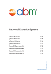
MCB1700 Board Overview
The Keil MCB1700 board is populated with NXP LPC1768 Microcontroller. Figure 6.1
shows the important interface and hardware components of the MCB1700 board.
Figure 6.2 is the hardware block diagram that helps you to understand the MCB1700
board components. Note that our lab will only use a small subset of the components which
include the LPC1768 CPU, COM and Dual RS232.
The LPC1768 is a 32-bit ARM Cortex-M3 microcontroller for embedded applications
requiring a high level of integration and low power dissipation. The LPC1768 operates at
up to an 100 MHz CPU frequency. The peripheral complement of LPC1768 includes 512KB
of on-chip flash memory, 64KB of on-chip SRAM and a variety of other on-chip peripherals.
Among the on-chip peripherals, there are system control block, pin connect block, 4 UARTs
and 4 general purpose timers, some of which will be used in your RTX course project.
Figure 6.3 is the simplified LPC1768 block diagram [4], where the components to be used
in your RTX project are circled with red. Note that this manual will only discuss the
components that are relevant to the RTX course project. The LPC17xx User Manual is
the complete reference for LPC1768 MCU.
6.2
Cortex-M3 Processor
The Cortex-M3 processor is the central processing unit (CPU) of the LPC1768 chip. The
processor is a 32-bit microprocessor with a 32-bit data path, a 32-bit register bank, and
23
Figure 6.1: MCB1700 Board Components [1]
Figure 6.2: MCB1700 Board Block Diagram [1]
24
Figure 6.3: LPC1768 Block Diagram
25
Figure 6.4: Simplified Cortex-M3 Block Diagram[5]
32-bit memory interfaces. Figure 6.4 is the simplified block diagram of the Cortex-M3
processor [5]. The processor has private peripherals which are system control block, system
timer, NVIC (Nested Vectored Interrupt Controller) and MPU (Memory Protection Unit).
The MPU programming is not required in the course project. The processor includes
a number of internal debugging components which provides debugging features such as
breakpoints and watchpoints.
6.2.1
Registers
The processor core registers are shown in Figure 6.5. For detailed description of each
register, Chapter 34 in [4] is the complete reference.
• R0-R12 are 32-bit general purpose registers for data operations. Some 16-bit Thumb
instructions can only access the low registers (R0-R7).
• R13(SP) is the stack pointer alias for two banked registers shown as follows:
– Main Stack Pointer (MSP): This is the default stack pointer and also reset
value. It is used by the OS kernel and exception handlers.
– Process Stack Pointer (PSP): This is used by user application code.
26
Figure 6.5: Cortex-M3 Registers[4]
On reset, the processor loads the MSP with the value from address 0x00000000. The
lowest 2 bits of the stack pointers are always 0, which means they are always word
aligned.
In Thread mode, when bit[1] of the CONTROL register is 0, MSP is used. When
bit[1] of the CONTROL register is 1, PSP is used.
• R14(LR) is the link register. The return address of a subroutine is stored in the link
register when the subroutine is called.
• R15(PC) is the program counter. It can be written to control the program flow.
• Special Registers are as follows:
– Program Status registers (PSRs)
– Interrupt Mask registers (PRIMASK, FAULTMASK, and BASEPRI)
– Control register (CONTROL)
When at privilege level, all the registers are accessible. When at unprivileged (user) level,
access to these registers are limited.
27
6.2.2
Processor mode and privilege levels
The Cortex-M3 processor supports two modes of operation, Thread mode and Handler
mode.
• Thread mode is entered upon Reset and is used to execute application software.
• Handler mode is used to handle exceptions. The processor returns to Thread mode
when it has finished exception handling.
Software execution has two access levels, Privileged level and Unprivileged (User) level.
• Privileged
The software can use all instructions and has access to all resources. Your RTOS
kernel functions are running in this mode.
• Unprivileged (User)
The software has limited access to MSR and MRS instructions and cannot use the
CPS instruction. There is no access to the system timer, NVIC , or system control
block. The software might also have restricted access to memory or peripherals. User
processes such as the wall clock process should run at this level.
When the processor is in Handler mode, it is at the privileged level. When the processor
is in Thread mode, it can run at privileged or unprivileged (user) level. The bit[0] in
CONTROL register determines the execution privilege level. Figure 6.6 illustrate the
mode and privilege level of the processor.
Figure 6.6: Cortex-M3 Operating Mode and Privilege Level[5]
Note that only privileged software can write to the CONTROL register to change the
privilege level for software execution in Thread mode. Unprivileged software can use the
28
SVC instruction to make a supervisor call to transfer control to privileged software. Another
way to change between Privileged Thread mode and Unprivileged thread mode is to modify
the EXC RETURN value in the LR (R14) when returning from an exception. You probably
want to use this mechanism for context switching.
6.2.3
Stacks
The processor uses a full descending stack. This means the stack pointer indicates the last
stacked item on the stack memory. When the processor pushes a new item onto the stack,
it decrements the stack pointer and then writes the item to the new memory location.
The processor implements two stacks, the main stack and the process stack. One of
these two stacks is banked out depending on the stack in use. This means only one stack
is visible at a time as R13. In Handler mode, the main stack is always used. The bit[1] in
CONTROL register reads as zero and ignores writes in Handler mode. In Thread mode,
the bit[1] setting in CONTROL register determines whether the main stack or the process
stack is currently used. Table 6.1 summarizes the processor mode, execution privilege level,
and stack use options.
Processor
mode
Thread
Used to
execute
Applications
Handler
Exception handlers
Privilege level for
software execution
Privileged
Unprivileged
Privileged
CONTROL
Bit[0] Bit[1]
0
0
1
1
0
Stack used
Main Stack
Process Stack
Main Stack
Table 6.1: Summary of processor mode, execution privilege level, and stack use options
6.3
Memory Map
The Cortex-M3 processor has a single fixed 4GB address space. Table 6.2 shows how this
space is used on the LPC1768.
Note that the memory map is not continuous. For memory regions not shown in the
table, they are reserved. When accessing reserved memory region, the processor’s behavior
is not defined. All the peripherals are memory-mapped and the LPC17xx.h file defines the
data structure to access the memory-mapped peripherals in C.
29
Address Range
0x0000 0000 to
0x1FFF FFFF
0x2000 0000 to
0x3FFF FFFF
0x4000 0000 to
0x5FFF FFFF
General Use
On-chip non-volatile
memory
On-chip SRAM
Boot ROM
On-chip SRAM
(typically used for
peripheral data)
GPIO
APB Peripherals
AHB peripherals
0xE000 0000 to
0xE00F FFFF
Cortex-M3 Private
Peripheral Bus (PPB)
Address range details
0x0000 0000 − 0x0007 FFFF
Description
512 KB flash memory
0x1000
0x1FFF
0x2007
0x2008
0000 − 0x1000
0000 − 0x1FFF
C000 − 0x2007
0000 − 0x2008
7FFF
1FFF
FFFF
3FFF
32 KB local SRAM
8 KB Boot ROM
AHB SRAM - bank0 (16 KB)
AHB SRAM - bank1 (16 KB)
0x2009
0x4000
0x4008
0x5000
C000 − 0x2009
0000 − 0x4007
0000 − 0x400F
0000 − 0x501F
FFFF
FFFF
FFFF
FFFF
GPIO
APB0 Peripherals
APB1 Peripherals
DMA Controller, Ethernet
interface, and USB interface
Cortex-M3 private registers(NVIC,
MPU and SysTick Timer et. al.)
0xE000 0000 − 0xE00F FFFF
Table 6.2: LPC1768 Memory Map
6.4
Exceptions and Interrupts
The Cortex-M3 processor supports system exceptions and interrupts. The processor and
the Nested Vectored Interrupt Controller (NVIC) prioritize and handle all exceptions. The
processor uses Handler mode to handle all exceptions except for reset.
6.4.1
Vector Table
Exceptions are numbered 1-15 for system exceptions and 16 and above for external interrupt
inputs. LPC1768 NVIC supports 35 vectored interrupts. Table 6.3 shows system exceptions
and some frequently used interrupt sources. See Table 50 and Table 639 in [4] for the
complete exceptions and interrupts sources. On system reset, the vector table is fixed
at address 0x00000000. Privileged software can write to the VTOR (within the System
Control Block) to relocate the vector table start address to a different memory location,
in the range 0x00000080 to 0x3FFFFF80.
6.4.2
Exception Entry
Exception entry occurs when there is a pending exception with sufficient priority and either
• the processor is in Thread mode
30
Exception
number
1
2
3
4
IRQ
number
-14
-13
-12
Vector address
or offset
0x00000004
0x00000008
0x0000000C
0x00000010
Exception
type
Reset
NMI
Hard fault
Memory
management fault
Priority
C PreFix
-3, the highest
-2,
-1
Configurable
NMI
HardFault
MemManage
..
.
11
..
.
-5
0x0000002C
SVCall
Configurable
SVC
-2
-1
0
1
2
3
4
5
6
7
8
0x00000038
0x0000003C
0x00000040
0x00000044
0x00000048
0x0000004C
0x00000050
0x00000054
0x00000058
0x0000005C
0x00000060
PendSV
SysTick
WDT
Timer0
Timer1
Timer2
Timer3
UART0
UART1
UART2
UART3
Configurable
Configurable
Configurable
Configurable
Configurable
Configurable
Configurable
Configurable
Configurable
Configurable
Configurable
PendSVC
SysTick
WDT IRQ
TIMER0 IRQ
TIMER1 IRQ
TIMER2 IRQ
TIMER3 IRQ
UART0 IRQ
UART1 IRQ
UART2 IRQ
UART3 IRQ
14
15
16
17
18
19
20
21
22
23
24
..
.
Table 6.3: LPC1768 Exception and Interrupt Table
• the processor is in Handler mode and the new exception is of higher priority than
the exception being handled, in which case the new exception preempts the original
exception (This is the nested exception case which is not required in our RTOS lab).
When an exception takes place, the following happens
• Stacking
When the processor invokes an exception (except for tail-chained or a late-arriving
exception, which are not required in the RTOS lab), it automatically stores the
following eight registers to the SP:
– R0-R3, R12
– PC (Program Counter)
– PSR (Processor Status Register)
– LR (Link Register, R14)
31
Figure 6.7 shows the exception stack frame. Note that by default the stack frame is
aligned to double word address starting from Cortex-M3 revision 2. The alignment
feature can be turned off by programming the STKALIGN bit in the System Control
Block (SCB) Configuration Control Register (CCR) to 0. On exception entry, the
processor uses bit[9] of the stacked PSR to indicate the stack alignment. On return
from the exception, it uses this stacked bit to restore the correct stack alignment.
Figure 6.7: Cortex-M3 Exception Stack Frame [5]
• Vector Fetching
While the data bus is busy stacking the registers, the instruction bus fetches the
exception vector (the starting address of the exception handler) from the vector
table. The stacking and vector fetch are performed on separate bus interfaces, hence
they can be carried out at the same time.
• Register Updates
After the stacking and vector fetch are completed, the exception vector will start to
execute. On entry of the exception handler, the following registers will be updated
as follows:
– SP: The SP (MSP or PSP) will be updated to the new location during stacking.
Stacking from the privileged/unprivileged thread to the first level of the exception handler uses the MSP/PSP. During the execution of exception handler
routine, the MSP will be used when stack is accessed.
– PSR: The IPSR will be updated to the new exception number
32
– PC: The PC will change to the vector handler when the vector fetch completes
and starts fetching instructions from the exception vector.
– LR: The LR will be updated to a special value called EXC RETURN. This indicates
which stack pointer corresponds to the stack frame and what operation mode
the processor was in before the exception entry occurred.
– Other NVIC registers: a number of other NVIC registers will be updated .For
example the pending status of exception will be cleared and the active bit of
the exception will be set.
6.4.3
EXC RETURN Value
EXC RETURN is the value loaded into the LR on exception entry. The exception mechanism
relies on this value to detect when the processor has completed an exception handler. The
EXC RETURN bits [31 : 4] is always set to 0xFFFFFFF by the processor. When this value is
loaded into the PC, it indicates to the processor that the exception is complete and the
processor initiates the exception return sequence. Table 6.4 describes the EXC RETURN bit
fields. Table 6.5 lists Cortex-M3 allowed EXC RETURN values.
Bits
Description
31:4
0xFFFFFFF
3
Return mode
(Thread/Handler)
2
Return stack
1
Reserved;
must be 0
0
Process state
(Thumb/ARM)
Table 6.4: EXC RETURN bit fields [5]
Value
0xFFFFFFF1
0xFFFFFFF9
0xFFFFFFFD
Return
Mode
Handler
Thread
Thread
Description
Exception return
gets state from
MSP
MSP
PSP
SP after return
MSP
MSP
PSP
Table 6.5: EXC RETURN Values on Cortex-M3
6.4.4
Exception Return
Exception return occurs when the processor is in Handler mode and executes one of the
following instructions to load the EXC RETURN value into the PC:
33
• a POP instruction that includes the PC. This is normally used when the EXC RETURN
in LR upon entering the exception is pushed onto the stack.
• a BX instruction with any register. This is normally used when LR contains the proper
EXC RETURN value before the exception return, then BX LR instruction will cause an
exception return.
• a LDR or LDM instruction with the PC as the destination. This is another way to load
PC with the EXC RETURN value.
Note unlike the ColdFire processor which has the RTE as the special instruction for
exception return, in Cortex-M3, a normal return instruction is used so that the whole
interrupt handler can be implemented as a C subroutine.
When the exception return instruction is executed, the following exception return sequences happen:
• Unstacking: The registers (i.e. exception stack frame) pushed to the stack will be
restored. The order of the POP will be the same as in stacking. The SP will also be
changed back.
• NVIC register update: The active bit of the exception will be cleared. The pending
bit will be set again if the external interrupt is still asserted, causing the processor
to reenter the interrupt handler.
6.5
Data Types
The processor supports 32-bit words, 16-bit halfwords and 8-bit bytes. It supports 64-bit
data transfer instructions. All data memory accesses are managed as little-endian.
34
Chapter 7
Keil Software Development Tools
The Keil MDK-ARM development tools are used for MCB1700 boards in our lab. The
tools include
• µVision4 IDE which combines the project manager, source code editor and program
debugger into one environment;
• ARM compiler, assembler, linker and utilities;
• ULINK USB-JTAG Adapter which allows you to debug the embedded programs
running on the board.
The MDK-Lite is the evaluation version and does not require a license. However it
has a code size limit of 32KB, which is adequate for your course projects. The MDK-Lite
version 4.60.0.0 1 is installed on all lab computers. If you want to install the software on
your own computer, Appendix A gives detailed instruction.
7.1
Creating an Application in µVision4 IDE
To get started with the Keil IDE, the MDK-ARM Primer
http : //www.keil.com/support/man/docs/gsac/
is a good place to start. We will walk you through the IDE by developing a simple
HelloWorld application which displays Hello World through the UART0 that is connected
to the lab PC. Note the HelloWorld example uses polling rather than interrupt.
1
The latest version is 5.1.0.0 We have not fully tested the supplied sample code with this version. This
manual is based on version 4.60.0.0.
35
7.1.1
Create a New Project
1. Create a folder named “HelloWorld” on your computer.
2. Copy the following files to “HelloWorld” folder:
• manual code\UART polling\src\uart polling.h
• manual code\UART polling\src\uart polling.c
• manual code\Startup\system LPC17xx.c
3. Create a new µVision project by click
• Project → New µVision Project (See Figure 7.1)
Figure 7.1: Keil IDE: Create a New Project
• Choose NXP(Founded by Philips) → LPC1768 (See Figure 7.2(a) and Figure
7.2(b))
• Answer “Yes” to copy the startup code (See Figure 7.3).
7.1.2
Managing Project Components
You just finished creating a new project. One the left side of the IDE is the Project window
and expand all objects, you will see the default project setup as shown in Figure 7.4.
1. Rename the Target
The “Target 1” is the default name of the project build target and you can rename
it by clicking the target name to highlight it and then click the highlighted name to
input a new target name, say “HelloWorld SIM”
2. Rename the Source Group
The IDE allows you to group source files to different groups to better manage
the source code. By default “Source Group 1” is created and the startup code
36
(a) Choose NXP
(b) Choose LPC1768
Figure 7.2: Keil IDE: Choose MCU
Figure 7.3: Keil IDE: Copy Startup Code
“startup LPC17xx.s” is put under this source group. You can rename the source
group by clicking the source group name to highlight it and then click again to input
a new name, say “Startup Code”.
3. Add a New Source Group
You can add new source groups to your project. Click “Project → Manage” →
“Components, Environment, Books...” (See Figure 7.5 You can now add new source
groups to the project. Let’s add “System Code” and “Source Code” source groups
to the project (See Figure 7.6. Your project will now look like Figure 7.7
4. Add Source Code to a Source Group
Now add “system LPC17xx.c” to “System Code” group by double clicking the source
group and choose the file from the file window. Double clicking the file name will add
37
Figure 7.4: Keil IDE: A default new project
Figure 7.5: Keil IDE: Manage Project Components
Figure 7.6: Keil IDE: Manage Components Window
the file to the source group. Or you can select the file and click the “Add” button at
the lower right corner of the window (See Figure 7.8).
Similarly, add “uart polling.c” to “Source Code” group. Your project will now look
like Figure 7.9.
5. Create a new source file
The project does not have a main function yet. We now create a new file by clicking
the “New” button (See Figure 7.10). Before typing anything to the file, save the file
and name it “main.c”. Put the following code to the main.c file:
#include <LPC17xx.h>
#include "uart_polling.h"
38
Figure 7.7: Keil IDE: Updated Project Profile
Figure 7.8: Keil IDE: Add Source File to Source Group
int main() {
SystemInit();
uart0_init();
uart0_put_string("Hello World!\n\r");
return 0;
}
Then add main.c to the “Source Code” group. Your final project would look like the
screen shot in Figure 7.11.
39
Figure 7.9: Keil IDE: Updated Project Profile
Figure 7.10: Keil IDE: Create New File
Figure 7.11: Keil IDE: Final Project Setting
7.1.3
Build and Download
To build the target, click the “Build” button (see Figure 7.12). If nothing is wrong, the
build output window at the bottom of the IDE will show a log similar like the one shown
in Figure 7.13
To download the code to the board, click the “Load” button (see Figure 7.14). The
download is through the Ulink-Me.
You will need a terminal emulator such as PuTTY that talks directly to COM ports in
40
Figure 7.12: Keil IDE: Build Target
Figure 7.13: Keil IDE: Build Target
Figure 7.14: Keil IDE: Download Target to Flash
order to see output of the serial port. Open up the PuTTY on your PC and choose COM1.
An example PuTTY Serial configuration is shown in Figures 7.15(a) and 7.15(b). Press
the Reset button on the board and you should see “Hello World!” displayed on PuTTY.
41
(a) PuTTY Session for Serial Port Communication
7.2
(b) PuTTY Serial Port Configuration
Debugging
You can use either the simulator within the IDE or the ULINK Cortex Debugger to debug
your program. To start a debug session, click Debug→Start/Stop Debug Session from the
IDE menu bar or press Ctrl+F5. Figure 7.15 shows the a typical debug session interface.
As any other GUI debugger, the IDE allows you to set up break points and step
through your source code. It also shows the registers, which is very helpful for debugging
low level code. Click View, Debug and Peripherals from the IDE menu bar and explore
the functionality of the debugger.
7.2.1
Disabling CRP
In order to avoid stealing firmware , the LPC1768 provides Code Read Protection (CRP)
that allows fine-grain control about which areas of the memory can be read. A detailed
description is found in Section 32.6 of [4]. In essence if the Assembler Directive NO CRP
is not present, the hardware is initialized to only make the firmware read-only (see Figure
7.16)
Since it is advisable to change values on the fly when debugging, the CRP should be
disabled during prototyping. Open up the target option window and click the Asm tab.
Put “NO CRP” as shown in Figure 7.17
42
Figure 7.15: Keil IDE: Debugging
Figure 7.16: startup LPC17xx.s excerpt
Figure 7.17: Keil IDE: Using Simulator for Debugging
43
7.2.2
Simulation
Most of the development normally is done under the simulation mode. The default setting
of the project uses the simulator to debug as shown in the target option (see Figure 7.18
Instead of load the program to the board for execution, you can run the code using the
Figure 7.18: Keil IDE: Using Simulator for Debugging
debugger under simulation mode.
7.2.3
Configure In-Memory Execution Using ULINK Cortex Debugger
When you debug hardware related problems, you most likely will find the ULINK Cortex
Debugger is helpful. You need to configure the debugger as shown in Figure 7.19.
Figure 7.19: Keil IDE: Using ULINK Cortex Debugger
The default image memory map setting is that the code is executed from the ROM
(see Figure7.20(a). Since the ROM portion of the code needs to be flashed in order to
be executed on the board, this incurs wear-and-tear on the on-chip flash of the LPC1768.
Since most attempts to write a functioning RTX will eventually require some more or less
elaborate debugging, the flash memory might wear out quickly. Unlike the flash memory
stick file systems where the wear is aimed to be uniformly distributed across the memory
portion, this flash memory will get used over and over again in the same portion.
The ARM compiler can be configured to have a different starting address. We can
create a RAM target where the code starting address is in RAM (see Figure 7.20(b). An
44
initialization file RAM.ini (see Listing 7.1)is needed to do the proper setting of SP, PC and
vector table offset register.
(a) Default Memory Setting
(b) In-Memory Execution Setting
Figure 7.20: Keil IDE: Configure for In-Memory Execution
FUNC void Setup (void) {
SP = _RDWORD(0x10000000);
// Setup Stack Pointer
PC = _RDWORD(0x10000004);
// Setup Program Counter
_WDWORD(0xE000ED08, 0x10000000);
// Setup Vector Table
Offset Register
}
// You need to provide the path of the .axf file here
LOAD build\RAM\HelloWorld.axf INCREMENTAL
// Download
Setup();
// Setup for Running
g, main
Listing 7.1: The RAM.ini file
To download the code to the board, one should not use the download button. Instead,
the debug button is used to initiate a debug session and the RAM.ini file will load the code
to the board.
45
Chapter 8
Programming MCB1700
8.1
The Thumb-2 Instruction Set Architecture
The Cortex-M3 supports only the Thumb-2 (and traditional Thumb) instruction set. With
support for both 16-bit and 32-bit instructions in the Thumb-2 instruction set, there is no
need to switch the processor between Thumb state (16-bit instructions) and ARM state
(32-bit instructions).
In the RTOS lab, you will need to program a little bit in the assembler language. We
introduce a few assembly instructions that you most likely need to use in your project in
this section.
The general formatting of the assembler code is as follows:
label
opcode operand1, operand2, . . . ; Comments
The label is optional. Normally the first operand is the destination of the operation (note
STR is one exception).
Table 8.1 lists some assembly instructions that the RTX project may use. For complete
instruction set reference, we refer the reader to Section 34.2 (ARM Cortex-M3 User Guide:
Instruction Set) in [4].
8.2
ARM Architecture Procedure Call Standard (AAPCS)
The AAPCS (ARM Architecture Procedure Call Standard) defines how subroutines can be
separately written, separately compiled, and separately assembled to work together. The
46
Mnemonic
LDR
LDM
STR
MRS
MSR
PUSH
POP
BL
BLX
BX
Operands/Examples
Rt, [Rn, #offset]
LDR R1, [R0, #24]
Rn{!}, reglist
LDM R4, {R0 − R1}
Rt, [Rn, #offset]
STR R3, [R2, R6]
STR R1, [SP, #20]
Rd , spec reg
MRS R0, MSP
MRS R0, PSP
spec reg, Rm
MSR MSP, R0
MSR PSP, R0
reglist
PUSH {R4 − R11, LR}
reglist
POP {R4 − R11, PC}
label
BL funC
Rm
BLX R12
Rm
BX LR
Description
Load Register with word
Load word value from an memory address R0+24 into R1
Load Multiple registers
Load word value from memory address R4 to R0, increment the
address, load the value from the updated address to R1.
Store Register word
Store word in R3 to memory address R2+R6
Store word in R1 to memory address SP+20
Move from special register to general register
Read MSP into R0
Read PSP into R0
Move from general register to special register
Write R0 to MSP
Write R0 to PSP
Push registers onto stack
push in order of decreasing the register numbers
Pop registers from stack
pop in order of increasing the register numbers
Branch with Link
Branch to address labeled by funC, return address stored in LR
Branch indirect with link
Branch with link and exchange (Call) to an address stored in R12
Branch indirect
Branch to address in LR, normally for function call return
Table 8.1: Assembler instruction examples
47
C compiler follows the AAPCS to generate the assembly code. Table 8.2 lists registers
used by the AAPCS.
Register
r15
r14
r13
r12
r11
r10
r9
r8
r7
r6
r5
r4
r3
r2
r1
r0
Synonym
Special
PC
LR
SP
IP
v8
v7
v6
SB
TR
v5
v4
v3
v2
v1
a4
a3
a2
a1
Role in the procedure call standard
The Program Counter.
The Link Register.
The Stack Pointer (full descending stack).
The Intra-Procedure-call scratch register.
Variable-register 8.
Variable-register 7.
Platform register.
The meaning of this register is defined by platform standard.
Variable-register 5.
Variable-register 4.
Variable-register 3.
Variable-register 2.
Variable-register 1.
argument / scratch register 4
argument / scratch register 3
argument / result / scratch register 2
argument / result / scratch register 1
Table 8.2: Core Registers and AAPCS Usage
Registers R0-R3 are used to pass parameters to a function and they are not preserved.
The compiler does not generate assembler code to preserve the values of these registers.
R0 is also used for return value of a function.
Registers R4-R11 are preserved by the called function. If the compiler generated assembler code uses registers in R4-R11, then the compiler generate assembler code to automatically push/pop the used registers in R4-R11 upon entering and exiting the function.
R12-R15 are special purpose registers. A function that has the svc indirect keyword
makes the compiler put the first parameter in the function to R12 followed by an SVC
instruction. R13 is the stack pointer (SP). R14 is the link register (LR), which normally
is used to save the return address of a function. R15 is the program counter (PC).
Note that the exception stack frame automatically backs up R0-R3, R12, LR and
PC together with the xPSR. This allows the possibility of writing the exception handler in
purely C language without the need of having a small piece of assembly code to save/restore
R0-R3, LR and PC upon entering/exiting an exception handler routine.
48
8.3
Cortex Microcontroller Software Interface Standard (CMSIS)
The Cortex Microcontroller Software Interface Standard (CMSIS) was developed by ARM.
It provides a standardized access interface for embedded software products (see Figure 8.1).
This improves software portability and re-usability. It enables software solution suppliers
to develop products that can work seamlessly with device libraries from various silicon
vendors [2].
Figure 8.1: Role of CMSIS[5]
The CMSIS uses standardized methods to organize header files that makes it easy to
learn new Cortex-M microcontroller products and improve software portability. With the
<device>.h (e.g. LPC17xx.h) and system startup code files (e.g., startup_LPC17xx.s),
your program has a common way to access
• Cortex-M processor core registers with standardized definitions for NVIC, SysTick, MPU registers, System Control Block registers , and their core access functions
(see core cm ∗ .[ch] files).
• system exceptions with standardized exception number and handler names to
allow RTOS and middleware components to utilize system exceptions without having
compatibility issues.
• intrinsic functions with standardized name to produce instructions that cannot
be generated by IEC/ISO C.
• system initialization by common methods for each MCU. Fore example, the standardized SystemInit() function to configure clock.
• system clock frequency with standardized variable named as SystemFrequency
defined in the device driver.
49
• vendor peripherals with standardized C structure.
Figure 8.2: CMSIS Organization[2]
8.3.1
CMSIS files
The CMSIS is divided into multiple layers (See Figure 8.2). For each device, the MCU
vendor provides a device header file <device>.h (e.g., LPC17xx.h) which pulls in additional
header files required by the device driver library and the Core Peripheral Access Layer (see
Figure 8.3).
By including the <device>.h (e.g., LPC17xx.h) file into your code file. The first step
to initialize the system can be done by calling the CMSIS function as shown in Listing 8.1.
SystemInit(); // Initialize the MCU clock
Listing 8.1: CMSIS SystemInit()
The CMSIS compliant device drivers also contain a startup code (e.g., startup_LPC17xx.s),
which include the vector table with standardized exception handler names (See Section
8.3.3.
8.3.2
Cortex-M Core Peripherals
We only introduce the NVIC programming in this section. The Nested Vectored Interrupt
Controller (NVIC) can be accessed by using CMSIS functions (see Figure 8.4). As an
50
Figure 8.3: CMSIS Organization[2]
Figure 8.4: CMSIS NVIC Functions[2]
example, the following code enables the UART0 and TIMER0 interrupt
NVIC_EnableIRQ(UART0_IRQn); // UART0_IRQn is defined in LPC17xx.h
NVIC_EnableIRQ(TIMER0_IRQn); // TIMER0_IRQn is defined in LPC17xx.h
51
8.3.3
System Exceptions
Writing an exception handler becomes very easy. One just defines a function that takes
no input parameter and returns void. The function takes the name of the standardized
exception handler name as defined in the startup code (e.g., startup_LPC17xx.s). The
following listing shows an example to write the UART0 interrupt handler entirely in C.
void UART0_Handler (void)
{
// write your IRQ here
}
Another way is to use the embedded assembly code:
__asm void UART0_Handler(void)
{
; do some asm instructions here
BL __cpp(a_c_function) ; a_c_function is a regular C function
; do some asm instructions here,
}
8.3.4
Intrinsic Functions
ANSI cannot directly access some Cortex-M3 instructions. The CMSIS provides intrinsic
functions that can generate these instructions. The CMSIS also provides a number of
functions for accessing the special registers using MRS and MSR instructions. The intrinsic
functions are provided by the RealView Compiler. Table 8.3 lists some intrinsic functions
that your RTOS project most likely will need to use. We refer the reader to Tables 613
and 614 one page 650 in Section 34.2.2 of [4] for the complete list of intrinsic functions.
8.3.5
Vendor Peripherals
All vendor peripherals are organized as C structure in the <device>.h file (e.g., LPC17xx.h).
For example, to read a character received in the RBR of UART0, we can use the following
code.
unsigned char ch;
ch = LPC_UART0->RBR; // read UART0 RBR and save it in ch
52
Instruction
CPSIE I
CPSID I
Special Register
CONTROL
MSP
PSP
Access
Read
Write
Read
Write
Read
Write
CMSIS Intrinsic Function
void enable irq(void)
void disable irq(void)
CMSIS Function
uinit32 t get CONTROL(void)
void set CONTROL(uint32 t value)
uinit32 t get MSP(void)
void set MSP(uint32 t value)
uinit32 t get PSP(void)
void set PSP(uint32 t value)
Table 8.3: CMSIS intrinsic functions defined in core cmFunc.h
8.4
Accessing C Symbols from Assembly
Only embedded assembly is support in Cortex-M3 (i.e. inline assembly is not supported).
To write an embedded assembly function, you need to use the asm keyword. For example the the function “embedded asm function” in Listing 8.2 is an embedded assembly
function. You can only put assembly instructions inside this function. Note that inline
assembly is not supported in Cortex-M3.
The cpp keyword allows one to access C compile-time constant expressions, including
the addresses of data or functions with external linkage, from the assembly code. The
expression inside the cpp can be one of the followings:
• A global variable defined in C
typedef struct pcb {
struct * mp_next;
uint32_t m_sp;
//.....
} pcb_t;
pcb_t g_pcb;
uint32_t g_var;
__asm embedded_asm_function(void) {
LDR R3, =__cpp(&g_pcb) ; load R3 with the address of g_pcb
LDM R3, {R1, R2}
; load R1 with g_pcb.mp_next
; load R2 with g_pcb.m_sp
LDR R4, =__cpp(g_var) ; load R4 with the value of g_var
53
}
Listing 8.2: Example of accessing global variable from assembly
• A C function
extern void a_c_function(void);
...
__asm embedded_asm_function(void) {
;......
BL __cpp(a_c_function) ; a_c_function is regular C function
;......
}
• A constant expression in the range of 0 − 255 defined in C.
uint8_t const g_flag;
__asm embedded_asm_function(void) {
;......
MOV R4, #_cpp(g_flag) ; load g_flag value to R4
;......
}
Note the MOV instruction only applies to immediate constant value in the range of
0 − 255.
You can also use the IMPORT directive to import a C symbol in the embedded assembly
function and then start to use the imported symbol just as a regular assembly symbol. For
example
void a_c_function (void) {
// do something
}
__asm embedded_asm_add(void) {
IMPORT a_c_function ; a_c_function is a regular C function
BL a_c_function
; branch with link to a_c_function
}
54
Names in the __cpp expression are looked up in the C context of the __asm function.
Any names in the result of the __cpp expression are mangled as required and automatically
have IMPORT statements generated from them.
8.5
UART Programming
To program a UART on MCB1700 board, one first needs to configure the UART by
following the steps listed in Section 15.1 in [4] (referred as LPC17xx UM in the sample
code comments). Listings 8.3 and 8.4 give one sample implementation of programming
UART0 interrupts.
/**
* @file uart.h
*/
#ifndef _UART_H_
#define _UART_H_
#include <stdint.h> // typedefs
// The following
#define IER_RBR
#define IER_THRE
#define IER_RLS
macros are from NXP uart.h
0x01
0x02
0x04
#define
#define
#define
#define
#define
IIR_PEND
IIR_RLS
IIR_RDA
IIR_CTI
IIR_THRE
0x01
0x03
0x02
0x06
0x01
#define
#define
#define
#define
#define
#define
#define
#define
LSR_RDR 0x01
LSR_OE 0x02
LSR_PE 0x04
LSR_FE 0x08
LSR_BI 0x10
LSR_THRE 0x20
LSR_TEMT 0x40
LSR_RXFE 0x80
55
#define BUFSIZE 0x40
// end of NXP uart.h file reference
#define BIT(X) ( 1<<X )
#define UART_8N1 0x83 // 8 bits, no Parity, 1 Stop bit
// 0x83 = 1000 0011 = 1 0 00 0 0 11
// LCR[7] =1 enable Divisor Latch Access Bit DLAB
// LCR[6] =0 disable break transmission
// LCR[5:4]=00 odd parity
// LCR[3] =0 no parity
// LCR[2] =0 1 stop bit
// LCR[1:0]=11 8-bit char len
// See table 279, pg306 LPC17xx_UM
#define uart0_init()
uart_init(0)
int uart_init(int n_uart); // initialize the n_uart
void uart_send_string( uint32_t n_uart, uint8_t *p_buffer, uint32_t len );
// write a string to the n_uart
#endif // ! _UART_H_
Listing 8.3: UART0 IRQ Sample Code uart.h
/**
* @file uart_irq.c
* @brief uart interrupt setup and handling functions
*/
#include <LPC17xx.h>
#include "uart.h"
volatile uint8_t g_UART0_TX_empty=1;
volatile uint8_t g_UART0_buffer[BUFSIZE];
volatile uint32_t g_UART0_count = 0;
/**
* @brief: initialize the n_uart
* NOTES: only fully supports uart0 so far, but can be easily extended
* to other uarts. The step number in the comments matches the
* item number in Section 14.1 on pg 298 of LPC17xx_UM
*/
56
int uart_init(int n_uart) {
LPC_UART_TypeDef *pUart;
if (n_uart ==0 ) {
// Steps 1 & 2: system control configuration.
//
Under CMSIS, system_LPC17xx.c does these two steps
// Step 1: Power control configuration, table 46 pg63 in LPC17xx_UM
// enable UART0 power, this is the default setting
// done in system_LPC17xx.c under CMSIS
// enclose the code for your refrence
//LPC_SC->PCONP |= BIT(3);
// Step2: select the clock source, default PCLK=CCLK/4 ,
// where CCLK = 100MHZ.
// tables 40 and 42 on pg56 and pg57 in LPC17xx_UM
// Check the PLL0 configuration to see how XTAL=12.0MHZ gets to
// CCLK=100MHZ in system_LPC17xx.c file
// enclose the code for your reference
//LPC_SC->PCLKSEL0 &= ~(BIT(7)|BIT(6));
// Step 5: Pin Ctrl Block configuration for TXD and RXD
// See Table 79 on pg108 in LPC17xx_UM for pin settings
// Done before Steps3-4 for better coding purpose.
LPC_PINCON->PINSEL0 |= (1 << 4); // Pin P0.2 used as TXD0 (Com0)
LPC_PINCON->PINSEL0 |= (1 << 6); // Pin P0.3 used as RXD0 (Com0)
pUart = (LPC_UART_TypeDef *) LPC_UART0;
} else if (n_uart == 1) {
// see Table 79 on pg108 in LPC17xx_UM for pin settings
LPC_PINCON->PINSEL0 |= (2 << 0); // Pin P2.0 used as TXD1 (Com1)
LPC_PINCON->PINSEL0 |= (2 << 2); // Pin P2.1 used as RXD1 (Com1)
pUart = (LPC_UART_TypeDef *) LPC_UART1;
57
} else {
return 1; // not supported yet
}
// Step 3: Transmission Configuration
// Step 3a: DLAB=1, 8N1
pUart->LCR = UART_8N1;// see uart.h file
// Step 3b: 115200 baud rate @ 25.0 MHZ PCLK
// seep section 14.4.12.1 pg313-315 in LPC17xx_UM for baud rate
calculation
pUart->DLM = 0;
// see table 274, pg302 in LPC17xx_UM
pUart->DLL = 9;
// see table 273, pg302 in LPC17xx_UM
pUart->FDR = 0x21;
// FR = 1.507 ~ 1/2, DivAddVal = 1, MulVal = 2
// FR = 1.507 = 25MHZ/(16*9*115200)
// see table 285 on pg312 in LPC_17xxUM
// Step 4 FIFO setup
pUart->FCR = 0x07; // enable Rx and Tx FIFOs, clear Rx and Tx FIFOs
// Trigger level 0 (1 char per interrupt)
// see table 278 on pg305 in LPC17xx_UM
// Step 5 was done between step 2 and step 4 a few lines above
// Step 6 Interrupt setting
// Step 6a: enable interrupt bits wihtin the specific peripheral
register
// Interrupt Sources Setting: RBR, THRE or RX Line Stats
// See Table 50 on pg73 in LPC17xx_UM for all possible UART0
// interrupt sources.
// See Table 275 on pg 302 in LPC17xx_UM for IER setting
pUart->LCR &= ~(BIT(7)); // disable the Divisior Latch Access Bit DLAB=0
pUart->IER = IER_RBR | IER_THRE | IER_RLS;
// Step 6b: enable the UART interrupt from the system level
// Use CMSIS call
58
NVIC_EnableIRQ(UART0_IRQn);
return 0;
}
/**
* @brief: use CMSIS ISR for UART0 IRQ Handler
* NOTE: This example shows how to save/restore all registers rather than
just
*
those backed up by the exception stack frame. We add extra
*
push and pop instructions in the assembly routine.
*
The actual c_UART0_IRQHandler does the rest of irq handling
*/
__asm void UART0_IRQHandler(void)
{
PRESERVE8
IMPORT c_UART0_IRQHandler
PUSH{r4-r11, lr}
BL c_UART0_IRQHandler
POP{r4-r11, pc}
}
/**
* @brief: c UART0 IRQ Handler
*/
void c_UART0_IRQHandler(void)
{
uint8_t IIR_IntId;
// Interrupt ID from IIR
uint8_t LSR_Val;
// LSR Value
uint8_t dummy = dummy; // dummy variable to clear interrupt upon LSR
error
LPC_UART_TypeDef * pUart = (LPC_UART_TypeDef *)LPC_UART0;
// Reading IIR automatically acknowledges the interrupt
IIR_IntId = (pUart->IIR) >> 1 ; // skip pending bit in IIR
if (IIR_IntId & IIR_RDA) { // Receive Data Avaialbe
// Note: read RBR will clear the interrupt
g_UART0_buffer[g_UART0_count++] = pUart->RBR; // read from the uart
if ( g_UART0_count == BUFSIZE ) {
g_UART0_count = 0; // buffer overflow
59
}
} else if (IIR_IntId & IIR_THRE) { // THRE Interrupt,
// transmit holding register empty
LSR_Val = pUart->LSR;
if(LSR_Val & LSR_THRE) {
g_UART0_TX_empty = 1; // UART is ready to transmit
} else {
g_UART0_TX_empty = 0; // UART is not ready to transmit yet
}
} else if (IIR_IntId & IIR_RLS) {
LSR_Val = pUart->LSR;
if (LSR_Val & (LSR_OE|LSR_PE|LSR_FE|LSR_RXFE|LSR_BI) ) {
// There are errors or break interrupt
// Read LSR will clear the interrupt
dummy = pUart->RBR; // Dummy read on RX to clear interrupt,
// then bail out
return ; // error occurs, return
}
// If no error on RLS, normal ready, save into the data buffer.
// Note: read RBR will clear the interrupt
if (LSR_Val & LSR_RDR) { // Receive Data Ready
g_UART0_buffer[g_UART0_count++] = pUart->RBR; // read from the uart
if ( g_UART0_count == BUFSIZE ) {
g_UART0_count = 0; // buffer overflow
}
}
} else { // IIR_CTI and reserved combination are not implemented yet
return;
}
}
void uart_send_string( uint32_t n_uart, uint8_t *p_buffer, uint32_t len )
{
LPC_UART_TypeDef *pUart;
if(n_uart == 0 ) { // UART0 is implemented
pUart = (LPC_UART_TypeDef *) LPC_UART0;
} else { // other UARTs are not implemented
return;
60
}
while ( len != 0 ) {
// THRE status, contain valid data
while ( !(g_UART0_TX_empty & 0x01) );
pUart->THR = *p_buffer;
g_UART0_TX_empty = 0; // not empty in the THR until it shifts out
p_buffer++;
len--;
}
return;
}
Listing 8.4: UART0 IRQ Sample Code uart irq.c
8.6
Timer Programming
To program a TIMER on MCB1700 board, one first needs to configure the TIMER by
following the steps listed in Section 21.1 in [4]. Listings 8.5 and 8.6 give one sample
implementation of programming TIMER0 interrupts. The timer interrupt fires every one
millisecond.
/**
* @file timer.h
*/
#ifndef _TIMER_H_
#define _TIMER_H_
extern uint32_t timer_init ( uint8_t n_timer ); // initialize timer
n_timer
#endif // ! _TIMER_H_
Listing 8.5: Timer0 IRQ Sample Code timer.h
/**
* @file timer.c
* @brief Timer irq setup and handling routine.
*/
61
#include <LPC17xx.h>
#include "timer.h"
#define BIT(X) (1<<X)
volatile uint32_t g_timer_count = 0; // increment every 1 ms
/**
* @brief: initialize timer. Only timer 0 is supported
*/
uint32_t timer_init(uint8_t n_timer)
{
LPC_TIM_TypeDef * pTimer;
if (n_timer == 0) {
// Steps 1 & 2: system control configuration.
//
Under CMSIS, system_LPC17xx.c does these two steps
// Step 1: Power control configuration, table 46 pg63 in LPC17xx_UM
// enable TIMER0 power, this is the default setting
// done in system_LPC17xx.c under CMSIS
// enclose the code for your refrence
//LPC_SC->PCONP |= BIT(1);
// Step2: select the clock source, default PCLK=CCLK/4 ,
// where CCLK = 100MHZ.
// tables 40 and 42 on pg56 and pg57 in LPC17xx_UM
// Check the PLL0 configuration to see how XTAL=12.0MHZ
// gets to CCLK=100MHZ in system_LPC17xx.c file
// enclose the code for your reference
// LPC_SC->PCLKSEL0 &= ~(BIT(3)|BIT(2));
// Step 3: Pin Ctrl Block configuration.
// Optional, not used in this example
// See Table 82 on pg110 in LPC17xx_UM for pin settings
pTimer = (LPC_TIM_TypeDef *) LPC_TIM0;
} else {// other timer not supported yet
return 1;
62
}
// Step 4: Interrupts configuration
// Step 4.1: Prescale Register PR setting
pTimer->PR = 12499; // CCLK = 100 MHZ, PCLK = CCLK/4 = 25 MHZ
// 2*(12499 + 1)*(1/25) * 10^(-6) s = 10^(-3) s = 1
ms
// TC (Timer Counter) toggles b/w 0 and 1
// every 12500 PCLKs
// see MR setting below
// Step 4.2: MR setting, see section 21.6.7 on page 496 of LPC17xx_UM
pTimer->MR0 = 1;
// Step 4.3: MCR setting, see table 429 on page 496 of LPC17xx_UM
// Interrupt on MR0: when MR0 mathches the value in the TC,
// generate an interrupt
// Reset on MR0: Reset TC if MR0 mathches it.
pTimer->MCR = BIT(0) | BIT(1);
g_timer_count = 0;
// Step 4.4: CSMSIS enable timer0 IRQ
NVIC_EnableIRQ(TIMER0_IRQn);
// Step 4.5: Enable the TCR. See table 427 on page 494 of LPC17xx_UM
pTimer->TCR = 1;
return 0;
}
/**
* @brief: use CMSIS ISR for UART0 IRQ Handler
* NOTE: This example shows how to save/restore all registers rather than
just
*
those backed up by the exception stack frame. We add extra
*
push and pop instructions in the assembly routine.
*
The actual c_UART0_IRQHandler does the rest of irq handling
*/
63
__asm void TIMER0_IRQHandler(void)
{
PRESERVE8
IMPORT c_TIMER0_IRQHandler
PUSH{r4-r11, lr}
BL c_TIMER0_IRQHandler
POP{r4-r11, pc}
}
/**
* @brief: c UART0 IRQ Handler
*/
void c_TIMER0_IRQHandler(void)
{
LPC_TIM0->IR = BIT(0); // ack interrupt,
// see section 21.6.1 on pg 493 of LPC17XX_UM
g_timer_count++ ;
}
Listing 8.6: Timer0 IRQ Sample Code timer.c
64
Appendix A
MDK-ARM Installation
There is only a windows port for the Keil MDK-ARM for now. The MDK-ARM V4.60.0.0
direct download link is inside the Learn (http://learn.uwaterloo.ca) 1 .
During the process of the installation of the MDK-ARM, you will be asked to add
example code. Choose Keil(NXP) MCB1xxx Boards example projects (see Figure A.1).
Figure A.1: MDK-ARM Installation Steps: Choose Example Projects
1
The latest version of MDK-ARM is at Keil website http://www.keil.com/download/product/. However the lab manual is written for V4.60.0.0. We haven’t tested the latest version.
65
Figure A.2: MDK-ARM Installation Steps: Finish
At the last step of MDK-ARM installation, be sure that the launch the “ULINK Pro Driver
Figure A.3: MDK-ARM Installation Steps: ULINK Pro Driver
V1.0” driver installation check box is checked (see Figure A.2. Once you click “Finish”
button, the ULINK Pro Driver installation starts. Click “Install” button to install the
driver (see Figure A.3).
66
Appendix B
Forms
Lab administration related forms are given in this appendix.
67
SE350 Request to Leave a Project Group Form
Name:
Quest ID:
Student ID:
Lab Assignment ID
Group ID:
Names of Other Group Members:
Provide the reason for leaving the project group here:
Signature
Date
68
Bibliography
[1] MCB1700 User’s Guide. http://www.keil.com/support/man/docs/mcb1700. 24
[2] MDK Primer. http://www.keil.com/support/man/docs/gsac. 49, 50, 51
[3] Realview compilation tools version 4.0: Compiler reference guide, 2007-2010.
[4] LPC17xx User Manual, Rev2.0, 2010. 23, 26, 27, 30, 42, 46, 52, 55, 61
[5] J. Yiu. The Definitive Guide to the ARM Cortex-M3. Newnes, 2009. viii, 26, 28, 32,
33, 49
69