1
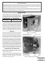
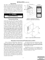
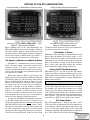
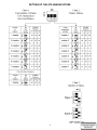
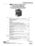
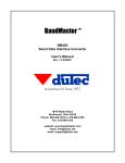
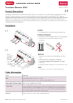
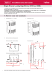
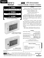
Owner’s
Manual
ATS Annunciator
Catalog 214A400, 214A401, 214A404
General
DANGER is used in this manual to warn of high
voltages capable of causing shock, burns, or death.
!
WARNING is used in this manual to warn
of possible personal injury.
!
CAUTION is used in this manual to warn
of possible equipment damage.
There are three types of ATS (Automatic Transfer
Switch) Annunciators. They are identified as follows:
Catalog 214A400 Master Unit
Catalog 214A404 Master Unit
used with a Network Supervisor
Catalog 214A401 Slave Unit
Each installation must have a master unit; each
master unit can support two slave units. Each unit can
annunciate four ATSs. Therefore a master and two
slave units can annunciate up to twelve ATSs. To
annunciate more ATSs, additional masters and slaves
can be added.
ASCO Catalog 214A400, 214A404, and 214A401
ATS Annunciators are designed to provide remote
visual status reporting and push button testing of ASCO
automatic transfer switches. Each ATS must have a
Group 1*, 5, 6, or 7 Microprocessor Controller with
Accessory 72A Serial Communication Interface Option
installed.
*Note: Group 1 Controller must have version 8 or
lower software (dash number on microprocessor).
Ratings
Master ATS Annunciator
Catalog 214A400, 214A404
Nominal Input Voltage . . . . . . . . 16 V ac 50 or 60 Hz,
. . . . . . . . . . . . or 12 or 24 V dc
Volt-Ampere Burden ➀ . . . . . . . 10 VA max @ 16 V ac
. . . . . . . 0.5 A max @ 24 V dc
Environmental Temperature Range ---20˚C. to +70˚C.
Transient Withstand . . . . . . . . per NEMA ICS 1---109
Surge Withstand (SWC) . . . . . . . IEEE Std 472---1974
. . . . . . ANSI C37.90A ---1974
Max total distance for Communication Line 4000 ft ➁
➀ (Master with 2 Slaves)
➁ For greater distances contact ASCO.
Table of Contents
section-page
Catalog 214A401
Slave ATS Annunciator
Iinstallation . . . . . . . . . . . . . . . . . . . . . . . . . . . . . 1-2
Setting Up the ATS Annunciator . . . . . . . . . . . 3-5
Operation and ATS Testing . . . . . . . . . . . . . . . . 6
Troubleshooting . . . . . . . . . . . . . . . . . . . . . . . . . . 7
An experienced licensed electrician must install the ATS
Annunciator.
50 Hanover Road, Florham Park, New Jersey 07932–1591 USA
For sales or service call 1 800 800–2726 (ASCO) www.ascopower.com
381333–063 B
ASCO POWER TECHNOLOGIES CANADA PO Box 1238, 17 Airport Road, Brantford, Ontario, Canada N3T 5T3
telephone 519 758–8450, fax 519 758–0876, for service call 1 888 234–2726 (ASCO) www.asco.ca
Serial Communications
Serial communications permits large amounts of information to be processed over a few wires. In the serial communications systems used by ASCO, each
individual device in the system --- automatic transfer switch, bypass-isolation switch, ATS annunciator, etc. --- has a unique code, or address, that is
assigned to it through DIP switches in the devices. According to the established ASCO serial communications rules, or protocol, each ATS annunciator
and/or the network supervisor on the communication link “talks” to all automatic transfer switches and other elements being monitored on the link at
the same time. They all “hear” what is being said, but only the device that is addressed responds.
Sending and receiving requests and commands is done over the same pair of twisted wires linked in a network fashion from one device to another to form
the communication link, or highway. This physical configuration comprises a network in which only the addressed device is permitted to go on line and
respond to an inquiry. With this serial communications system, a minimum number of wires can be used to link the elements together. Without serial
communications, it would take considerably more wires to accomplish the same thing.
INSTALLATION
The ATS Annunciator has been tested and is ready to use.
Installation simply requires mounting, connecting power
and communication wiring, and setting DIP switches. When
unpacking the unit, locate the loose parts which are supplied
in a separate kit. The kits contain the following parts:
Master Kit 401091
label holder labels
& 2 resistors
face plate screws
Slave Kit 401092
label holder labels,
2 resistors, & ribbon cable
The Master ATS Annunciator can be readily identified by
the front mounted key switch (to prevent unauthorized
operation). You will find the key taped inside the back
panel. Up to two Slave ATS Annunciators can be mounted
directly above or below the Master. All three ATS Annunciators are then interconnected by means of ribbon cables.
All external wiring for power and serial communication line
connects to the Master ATS Annunciator. Observe the
requirements of the National Electrical Code (especially
Articles 725 and 800) and any local codes when interwiring.
Mounting
cover
An Outline and Installation drawing (JS 387797) is included
in the back of this manual. The two---part enclosure, which
measures 10I wide x 6I high and 2I deep, is designed for
mounting to the standard wall boxes listed on the drawing.
After removing the front cover the hinged circuit board
opens to the right to expose the mounting holes in the base.
cover screws
Figure 1. Cover removal.
power wires, insulated ground wire,
and communication cable
hinged circuit board
Loosen four screws to remove the cover as shown in Figure 1.
Remove four screws and remove the face plate. Then remove
the two left standoffs and swing the hinged circuit board to the
right as shown in Figure 2. You will find the key taped to the
back panel. Run the power wires (and insulated ground wire)
and communication cable (twisted pairs) through the center
hole in the back of the enclosure, then to the right through the
notch in the circuit board. Attach the ATS Annunciator to the
wall box by using the mounting holes that line up. Swing the
circuit board closed again. Reinstall the two standoffs and
tighten them securely. Reinstall the face plate with four screws.
Connecting Slave ATS Annunciators
Connect the Slave ATS Annunciator(s), when used, to the
Master. Remove the adhesive labels from the slotted
openings as shown in Figure 2.
Then run the ribbon cable between ATS Annunciators and
plug each end into the adjacent sockets. Two Slaves may be
connected to one Master either by above and below
arrangement or two below arrangement. See the Outline
and Installation drawing for details.
slotted opening for ribbon
cable and removable label
standoff
face plate
Figure 2. Hinged circuit board (Master).
1
Power Wiring
INSTALLATION (continued)
The Master ATS Annunciator can be powered by
either an ac or dc source (but not both) as shown on the
Outline and Installation drawing 387797 and in Figure
3. For ac wiring use a Class 2 bell transformer with a
120 V ac primary and a 16 V ac secondary (12 VA
minimum). Connect the ac wiring to terminals 9 and
10; connect the ground to terminal 1. For dc wiring
connect a 12 or 24 V dc power source (750 ma) to
terminals 7 (---) and 8 (+).
Acceptable
Communication Cable
shield gnd
T+
Standard 80˚ C
T--R+
R--resistor on
Master 1 only
Belden 1419A
Belden 9842
Belden 9829
Alpha 6202C
Alpha 6222C
Plenum Rated
!
Belden 89729
Belden 82729
Alpha 58902
To prevent damage do not
energize the circuit at this time.
Figure 3. Terminal block (Master).
Located on right side of circuit board.
Communication Wiring
Connect one end of the transmit and receive communication cable (twisted pairs) to terminals 3 through 6
on the Master ATS Annunciator as shown on the
Outline and Installation drawing 387797 and in Figure
3. Refer to the Daisy Chain and Star configuration
hook up drawings for typical arrangements. Use
communication cable specified in Figure 3. This cable
has two twisted pairs (4 wires) and an overall shield.
All twisted pair shields must be connected to terminal
2 for grounding. The earth ground is connected to
terminal 1 and internally jumpered to terminal 2. Two
resistors are supplied. Connect one resistor (390 Ohm,
1/4 Watt, 5%) between terminals 5 and 6 on Master 1
only. See Figure 3. (The other resistor will be connected at the automatic transfer switch furthest away.)
Two twisted pairs can be connected to the ATS
Annunciator terminal block. Use a separate terminal
block (not supplied) mounted in a separate wall box if
more connections are necessary, as shown in Figure 4.
Figure 4. Typical separate terminal block.
Networks for Interconnecting ATS Annunciators and ATSs
Refer to Drawing JS 401900 Sheets 1 through 4 for
typical interconnection schemes. The Daisy Chain
configuration utilizes a single run of communication
cable with all of the equipment connected in parallel as
shown on Sheet No. 1. This type of network utilizes the
least amount of cable and is probably the most popular
approach when long line runs are anticipated. Depending on the desired reliability of the system, some
consideration should be given to the effect of a cable
break. If the cable is broken all ATSs beyond the break
will lose their communication. It should be kept in
mind that annunciator lamps will flash if a disconnection occurs. Also, a disconnection of the communications cable will in no way impair the operation of the
automatic transfer switch.
Star networks can be used as an alternate configuration as shown on Sheet No. 2. With this approach,
greater reliability can be achieved because a disconnect of the cable between the junction box and the ATS
will only impair one switch.
Depending on location of this equipment it may
sometimes be advantageous to use combinations of
Daisy Chain and Star networks. Typical configurations
are shown on Sheets No. 3 and 4.
2
SETTING UP THE ATS ANNUNCIATORS
Catalog 214A400, 214A404 Master ATS Annunciators
Catalog 214A401 Slave ATS Annunciator
Master ATS Annunciator factory default settings
Slave ATS Annunciator factory default settings
Figure 5. DIP switches in Master.
Before applying power to the ATS Annunciators, the
DIP switches must be set to select the number of Masters
and Slaves, Master Address, and the addresses of each
automatic transfer switch connected. Refer to Figures 5
and 6 for the location of DIP switches. See Charts 1, 2,
3, and 4 for position of actuators for each setting.
Figure 6. DIP switches in Slave.
5 Controller menu selection for the serial communication baud rate must be set to 9600.
Set Number of Slaves
DIP switch S1 shown in Figure 6, (on the left side of each
Slave) selects the number of the Slave (either 1 or 2).
Refer to Chart 3. For example, if only one Slave is used,
depress the actuators shown in the top figure (setting for
Slave 1). If two Slaves are used, set one to the setting for
Slave 1 and on the other Slave depress the actuators
shown in the lower figure (setting for Slave 2).
Set Number of Masters and Master Address
ASCOBUS I communication protocol supports
single– and multi–master, daisy chain, and star configurations. Group 7/7A and 5 Controllers can be
connected on the same network. In this case the Group
5 menu item selecting the serial communication baud
rate must be set to x9600.
When more than one Master is being used, one
Master must be selected as the Lead Master. Then the
Lead Master must be told how many other masters
there are. DIP switch S6 shown in Figure 5 on the
Master ATS Annunciator selects how many Masters
are being used (up to seven) and their addresses.
Actuators 1 through 3 set the number of Masters
(Chart 1 ) and actuators 4 through 6 set their addresses
(Chart 2). For example, if only one Master is used,
actuators 1 through 6 should be down (off). If more
than one Master is used, select one as a Lead Master
and set all other Masters to different address.
To select the ASCOBUS II communication protocol, the DIP switches S6 actuators 1,2,3 must be set to
ON position (ATS Annunciator must be deenergized).
With ASCOBUS II protocol selected, Group 1 and 5
Controllers can be connected on the same network and
the only configuration supported is the daisy chain
configuration with single master annunciator and up to
2 slaves (see drawing 401900). In this case the Group
Setting the ATS Address Number
DIP switches S2, S3, S4, and S5 on the ATS Master
(Figure 5) and Slave Annunciators (Figure 6) are used to
set the unique address number for each ATS. Up to 32
ATSs can be accommodated on a system utilizing three
Masters and five Slaves.
Actuator 1 must be on (up) for each address being used.
Refer to Chart 4 for selecting a unique address number
for each ATS. One DIP switch is used for each ATS.
For example, ATS 1 would use address 00 so set DIP
switch S2 (on the Master) with actuators 2---6 down
(off). ATS2 would use address 01 so set DIP switch S3
(on the Master) with actuator 6 up (on). Remember to
move actuator 1 up (on) for each DIP switch being
used! Refer to Table D at the back of this manual.
ATS Label Holder
The ATS Annunciator is labeled for ATS1, ATS2,
ATS3, and ATS4. Included with each ATS Annunciator
is an adhesive–backed label holder with labels for
ATS5 ---12 and some blank labels. Label each ATS
Annunciator with the ATS numbers that are addressed
in it. Fill in Table D at the back of this manual.
3
SETTING UP THE ATS ANNUNCIATORS
4
SETTING UP THE ATS ANNUNCIATORS
5
OPERATION
Catalog 214A400, 214A404, and 214A401 ATS
Annunciators communicate with ASCO automatic
transfer switches to report their status. Each automatic
transfer switch is continuously polled and reports its
status back to the ATS Annunciator. Lights on the front
indicate which automatic transfer switches are
connected to the normal source or emergency source.
Source availability is also reported.
to control their operation. A key switch prevents
unauthorized operation. The Transfer Test push button
simulates a normal source outage and transfers the
individual load to the emergency source, if available.
When the same push button is pressed again, it signals
the automatic transfer switch to retransfer back to
normal immediately. A Time Delay Active push button
bypasses any transfer time delay in process (Feature 2B
or 3A). Lights above each push button indicate that the
automatic transfer switch is in the test mode and in a time
delay mode.
In addition, the ATS Annunciators can send
commands to individual automatic transfer switches
HOW TO TEST AN AUTOMATIC TRANSFER
SWITCH FROM THE ATS ANNUNCIATOR
1. Insert the switch key and turn it clockwise to the
Unlock position as shown in Figure7.
2. Select the number of the automatic transfer switch
you want to test and find the Transfer Test push
button below the ATS number on the bottom row.
3. Press and hold the Transfer Test push button until
the amber light above it starts flashing.
4. Observe that the Emergency Source Available red
light comes on indicating that the generator has
started.
5. Observe that the Load Connected to Emergency red
light comes on (Normal light off) indicating that
the ATS has transferred.
6. Press the Transfer Test push button again to end the
test. The flashing amber light goes off.
Note: If Feature 3A Retransfer to Normal Time Delay
is used (Time Delay Active amber light comes on) the
retransfer may not occur for up to 30 minutes. To
bypass this time delay press the Time Delay Active push
button below the amber light.
7. Observe that the Load Connected to Normal green
light comes on (Emergency light off) indicating
that the ATS has retransferred.
Note: The Emergency Source Available red light goes off
when the emergency source is no longer available.
8. When testing is completed, turn the key switch
counterclockwise to the Lock position and remove
the key.
Note: If Feature 2B Transfer to Emergency Time Delay
is used (Time Delay Active) amber light comes on) the
transfer may not occur for up to 5 minutes. To bypass
this time delay press the Time Delay Active push button
below the amber light.
status lights
Load connected to
Source available
Time delay active
key switch
Time delay bypass
push button
Transfer test
Transfer test
push button
Figure 7. ATS Annunciator (Master)
6
TROUBLE-SHOOTING
Table A. Trouble Shooting the ATS Annunciator
Problem
Probable Cause
Corrective Action
1. Normal and Emergency
lights flash alternately on all
ATS Annunciators.
No communication made.
Incorrect, broken, or shorted
wiring between ATSs and
ATS Annunciators.
Recheck wiring; check for
shorted or open circuits.
Be sure correct twisted pairs
are connected.
2. Normal and Emergency
lights flash alternately on
only one Annunciator.
No communication made.
Addresses on ATSs do not
correspond to addresses on
ATS Annunciator.
Recheck address settings in
ATS Annunciator and ATS
Control Panels. They must
be the same.
3. Normal and Emergency
lights flash for only one ATS
column (not alternately)
Communication lost to that
ATS due to no power to ATS
location.
Check power and
communication lines at all
ATSs.
4. Normal and Emergency
lights flash for all ATS
columns (not alternately)
Communication lost due to
power failure at all ATSs, or
broken or shorted
communication line.
Check power and
communication lines at all
ATSs.
5. When Transfer Test is
pressed amber light does
not flash.
Key switch on Master ATS
Annunciator in Lock position.
Insert key and turn it to
Unlock position.
6. When Time Delay Bypass is
pressed amber light does
not go off.
Key switch on Master ATS
Annunciator in Lock position.
Key switch was turned to
Lock before test completed.
Insert key and turn it to
Unlock position.
If corrections do not resolve the problem, call your local ASCO Power
Technologies or Authorized Representative Office, or ASI. Furnish the
Serial No. and Catalog No. from the transfer switch nameplate.
7