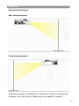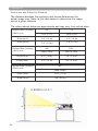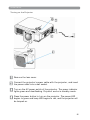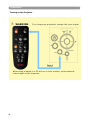
1
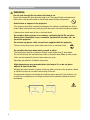
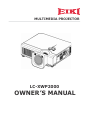
MULTIMEDIA PROJECTOR
LC-XWP2000
OWNER ’S MANUAL
About owner’s manual
Please read owner’s manual thoroughly to ensure correct usage of the projector
and its features. After reading, store owner’s manual in a safe place for future
reference.
Features
1. Design with 3LCD optical system.
2. Auto V keystone function, +/- 30 degrees.
3. Auto brightness control.
4. Auto ceiling function.
5. Extreme Short Throw Distance.
The content of this manual is subject to change without period notice. All rights reserved.
1
Contents
About owner’s manual . . . . . . . . . . . . . . . . . . . . . . . . . . . . . . . . . . . . . . . . . . . . . . .
1
Contents . . . . . . . . . . . . . . . . . . . . . . . . . . . . . . . . . . . . . . . . . . . . . . . . . . . . . . . . . . . .
2
Safety Instructions . . . . . . . . . . . . . . . . . . . . . . . . . . . . . . . . . . . . . . . . . . . . . . . . .
4
Product Safety Labels . . . . . . . . . . . . . . . . . . . . . . . . . . . . . . . . . . . . . . . . . . . . . . .
9
Checking the Package Contents . . . . . . . . . . . . . . . . . . . . . . . . . . . . . . . . . . . . . 10
Part Names and Functions . . . . . . . . . . . . . . . . . . . . . . . . . . . . . . . . . . . . . . . . . . 11
11
Main Unit .......................................................................................
13
Control Panel ...............................................................................
Rear View I/O Board ........................................................................ 15
Bottom View ................................................................................... 17
Remote Control ............................................................................... 18
Remote Control Batteries Installation ................................................. 19
Installation . . . . . . . . . . . . . . . . . . . . . . . . . . . . . . . . . . . . . . . . . . . . . . . . . . . . . . . . . 20
Setting Up the Projector ................................................................... 20
Screen size and Projection Distance .................................................... 22
Adjusting the Image Position ............................................................. 23
Moving the Projector ........................................................................ 24
Turning on the Projector.................................................................... 25
Connecting PC to the Projector ........................................................... 27
Connecting Video to the Projector ....................................................... 30
How to connect . . . . . . . . . . . . . . . . . . . . . . . . . . . . . . . . . . . . . . . . . . . . . . . . . . . . . 28
Desktop PC .................................................................................... 28
Laptop PC ...................................................................................... 29
Video ................................................................................ ............ 30
Basic Operation . . . . . . . . . . . . . . . . . . . . . . . . . . . . . . . . . . . . . . . . . . . . . . . . . . . . . 32
Turning on the Projector-Procedure ........................................................ 32
Turning off the Projector ....................................................................... 34
Adjusting the Screen Image .................................................................. 35
2
Co n t e n t s
Fu n c t i o n s o f M e n u ( OSD ) . . . . . . . . . . . . . . . . . . . . . . . . . . . . . . . . . . . . . . . . . . . .
Keypad Operat ing . .. . . . . . . . . .. .. . . . . . . . . . . . . . . .. . . . . . . . . . . . . . . . . .. . . . . . . . . . . . . .. . .. . . . . . . . . ..
Com put er Mode .. . . . . . . . . . . . .. .. . . . . . . . . . . . . . . .. . . . . . . . . . . . . .. . .. . . . . . . . . . . . . . .. . .. . . . . . . . .. .
Reset Lam p Tim er . .. . . . . . . . . .. .. . . . . . . . . . . . . . . .. . . . . . . . . . . . . . . . . .. . . . . . . . . . . . . .. . .. . . . . . . . . ....
Video m ode . . . . . . . .. .. . . . . . . . . . . . . .. .. . . . . . . . . . . . . .. .. . . . . . . . . . . . . . . .. . . . . . . . . . . . . . . .. .. . . . . ..
Ap p en d ix . . . . . . . . . . . . . . . . . . . . . . . . . . . . . . . . . . . . . . . . . . . . . . . . . . . . . . . . . . . .
Technical Specificat ions . . . .. .. . . . . . . . . . .. .. . . . . . . . . . . . . .. .. . . . . . . . . . . . . . . .. . . . . . . .............
36
36
37
43
44
50
50
M a i n t e n a n ce a n d Tr o u b l e sh o o t i n g .......................................................
Ceiling Mount ed I nst allat ion Guide . . . .. .. . . . . . . . . . .. .. . . . . . . . . . . . . .. .. . . . . . . . . . . . . . . .. . . . . . .
Cleaning t he Proj ect or . . . .. .. . . . . . . . . . .. .. . . . . . . . . . . . . .. .. . . . . . . . . . . . . . . .. . . . . . . .................
Cleaning t he Lens . . . .. .. . . . . . . . . . .. .. . . . . . . . . . . . . .. .. . . . . . . . . . . . . . . .. . . . . . . ......................
Cleaning Air Filt er . . . .. .. . . . . . . . . . .. .. . . . . . . . . . . . . .. .. . . . . . . . . . . . . . . .. . . . . . . ......................
Lam p Replacem ent . . . .. .. . . . . . . . . . .. .. . . . . . . . . . . . . .. .. . . . . . . . . . . . . . . .. . . . . . . ....................
I ndicat ors . . . . . . . .. .. . . . . . . . . . . . . .. .. . . . . . . . . . . . . .. .. . . . . . . . . . . . . . . .. . . . . . . . . . . . . . . .. .. . . . . ........
List of Suppor t Display Modes . . . .. .. . . . . . . . . . .. .. . . . . . . . . . . . . .. .. . . . . . . . . . . . . . . .. . . . . . . .
Configur at ions of Ter m inal . .. .. . . . . . . . . . . . . .. .. . . . . . . . . . . . . . . .. .. . . . . . . . . . . . . . . .. . . . . . . . . .
51
51
52
52
52
53
54
56
57
3
Safety Instructions
WARNING
This symbol indicates information that, if ignored, could possibly
result in personal injury or even death.
CAUTION
This symbol indicates information that, if ignored, could result in
personal injury or physical damage.
Typical Symbols
This symbol indicates an additional warning (including cautions).
An illustration is provided to clarify the contents (for example: the illustration to
the left indicates danger of electrical shock).
This symbol indicates a prohibited action. The contents will be clearly indicated in
an illustration or description near the symbol (for example: the symbol to the left
indicates that disassembly is prohibited).
This symbol indicates a compulsory action. The contents will be clearly indicated in
an illustration or description near the symbol (for example : the symbol to the left
shows that the power plug should be disconnected from the power outlet).
4
Safety Instructions(continued)
WARNING
If a problem should occur
If smoke or strange odors arise, continued use could result in fire or electrical shock. In
such case, immediately turn off the power switch and then disconnect the power plug
from the power outlet. After making sure that the smoke or odor has stopped, contact
your dealer for repairs. Never attempt to make repairs yourself because this is dangerous.
Do not use this projector if there is no image or sound, or if the sound is distorted.
Continued use could result in fire or electrical shock. In such case, immediately turn off
the power switch; disconnect the power plug from the power outlet and contact your
dealer.
If water would enter the inside of this projector, immediately turn off the power switch,
disconnect the power plug from the power outlet and contact your dealer.
Do not install on an unstable surface.
Do not install this projector on an unstable surface such as a wobbly stand or incline
because this could result in the projector falling and causing injury.
Do not open the cabinet.
Never open the cabinet. There is high voltage inside which can cause electrical shock.
Contact your dealer for internal inspection, adjustment and repair.
Do not modify.
Do not modify this projector because this could result in fire or electrical shock.
Do not use in the bathroom or near water site.
Do not expose this unit to rain or use near water… for example, in the bathroom, a wet
basement, near a swimming pool, etc…
Do not insert objects into the Projector.
Do not insert metal objects through the ventilation openings, etc., of this projector or drop
such objects inside because this could result in fire or electrical shock.
If a foreign object should enter this projector, immediately turn off the power
switch, disconnect the power plug from the power outlet and contact your
dealer.
Continued use could result in fire or electrical shock. Use special caution in household
and where children are present.
5
Safety Instructions(continued)
WARNING
Do not look through the lens when the lamp is on.
Never look through the lens when the lamp is on. The powerful light could adversely
affect vision. Use special caution in households where children are present.
Avoid shock or impact on the projector.
If the projector should fall, resulting in damage to the cabinet, immediately turn off the
power switch, disconnect the power plug from the power outlet and contact your dealer.
Continued use could result in fire or electrical shock.
Do not place this projector in a container containing liquid. Do not place
flower vases, flowerpots, cups, cosmetics, liquids such as water, etc., on
top of this projector.
Do not use any power cable except those supplied with the projector.
The use of any other power cable could result in fire or electrical shock.
Do not shine the laser beam onto yourself or other.
The laser pointer function of projector remote control emits class Ⅱ laser beam.
Do not look directly into the laser beam outlet or direct the laser beam at other people.
Vision can be impaired if the laser beam enters the eyes.
Especially pay attention if children are present.
High temperatures are generated when the lamp is lit; so do not place
objects in front of the lens.
Allowing the proper amount of space on the top, sides, and rear of the projector cabinet
is critical for proper air circulation and cooling of the unit.
The dimension shown here indicate the minimum space required. If the projector is to
be built into a compartment or similarly enclosed, these minimum distances must be
maintained.
6
Safety Instructions(continued)
CAUTION
Placing heavy objects on top of this projector could result in loss of balance or falling
and cause personal injury or damage the projector.
Do not block th ventilation openings.
Do not block the ventilatoin openings of this projector.
Blocking ventilation could lead to internal overheating which could result in fire.
Do not place this projector on its side during use or push it into a small, poorly ventilated
location.
Do not place this projector on a carpet or bedding or cover it with a tablecloth, etc. Also,
when installing this projector, make sure the ventilation openings are at least 30 cm (12
inch) clearance around the projector.
Care and maintenance.
For safety purposes, disconnect the power plug from the power outlet before starting the
care and maintenance of this projector.
Battery usage
Replace the batteries with the same type only.
Do not mix old and new batteries; this could result in fire or personal injury due to battery
cracking or leakage.
Make sure the plus and minus terminals are correctly aligned when loading the batteries.
Incorrect loading could redult in personal injury or contamination of the surroundings due
to battery cracking or leakage.
Have the projector interior cleaned regularly.
Contact your dealer to arrange for the service.
Accumulations of dust inside the projector can result in fire or malfunction if not cleaned
for an extended period.
Ask your dealer for details about internal cleaning.
7
Safety Instructions(continued)
CAUTION
Avoid installation in humid or dusty locations. Do not install this projector in a
humid or dusty location. This could result in fire or electrical shock.
Do not handle the power cord roughly. Keep the power cord away from heaters;
The heat could melt the power cord and cause fire or electrical shock.
Do not touch the power plug with wet hands;
This could result in electrical shock.
When disconnecting the power plug, do not pull on the power cord. This could
damage the power cord and cause fire or electrical shock. Always grip the
plug when disconnecting.
When the projector is not to be used for an extended period.
If the projector is not to be used for an extended period because of travel,
etc., disconnect the power plug from the power outlet and replace lens
cover.
Compliance
Federal communications Commission Notice
This equipment has been tested and found to comply with the limits for a Class B digital device, pursuant
to part 15 of the FCC Rules. These limits are designed to provide reasonable protection against harmful
interference in a residential installation. This equipment generates, uses, and can radiate radio frequency
energy and, if not installed and used in accordance with the instructions, may cause harmful interference
to radio communications. However, there is no guarantee that interference will not occur in a particular
installation. If this equipment does cause harmful interference to radio or television reception, which can
be determined by turning the equipment off and on, the user is encouraged to try to correct the
interference by one or more of the following measures:
-Reorient or relocate the receiving antenna.
-Increase the separation between the equipment and receiver.
-Connect the equipment into an outlet on a circuit different from that to which the receiver is connected.
-Consult the dealer or an experienced radio/TV technician for help.
Use of shielded cable is required to comply with class B limits in Subpart B of Part 15 of FCC Rules.
Do not make any changes or modifications to the equipment unless otherwise specified in the instructions.
If such changes or modifications should be made, you could be required to stop operation of the equipment.
Model Number(s): LC-XWP2000
Trade Name: EIKI
Responsible party: EIKI
Address : 30251 Esperanza Rancho Santa Margarita CA 92688-2132 U.S.A.
Telephone No. : 800-242-3454(949-457-0200)
NOTE: This symbol and recycle system are applied only to EU countries in the other area of
world.
Your EIKI product is designed and manufactured with high quality materials and components
which can be recycled and reused.
This symbol means that electrical and electronic equipment, at their end-of-life, should be
disposed of separately from your household waste.
Please dispose of this equipment at your local community waste collection/recycling centre.
In the European Union there are separate collection systems for used electrical and electronic
products. Please help us to conserve the environment we live in !
Voor de klanten in
Nederland
Bij dit product zijn batterijen
geleverd.
Wanneer deze leeg zijn, moet
u ze niet weggooien maar
inleveren als KCA.
8
Pr o d u ct sa f e t y l a b e l s
Safety labels are used on or within the projector to alert you to items or areas requiring your
attention.
LENS WARRANTY LABEL
EMI LABEL
EIKI
Model:LC-XIP2000
Input:
100-240V, 50/60Hz, 4A(1.2A~2.8A)
Serial no.:
Business card
LAMP WARRANTY LABEL
9
Checking the Package Contents
Remote Control
with batteries
Video Cable
Power Cord
S-Video Cable
Audio Cable
Computer cable
Speaker Cable
Projector
Quick Start Guide
/ Owner’s Manual CD
10
Carry Bag
(Optional)
Filter
RS232 Cable
(Optional)
Part Names and Functions:
Main Unit
3
IR sensor
1 Zoom ring
2 Focus ring
Speaker
4 Filter cover( bottom)
1 Zoom ring
Use the Zoom Ring to adjust the size of the projected image.
Rotate the Zoom Ring until the image is the desired size.
2 Focus ring
U s e t h e F o c u s R i n g t o f oc u s t h e p r o j e c t o r i m a g e .
Rotate the Focus Ring until the image is clear.
3 IR sensor
W h e n u s i n g t h e r e m o t e c o n t r o l , p o i n t t h e re m o t e c o n t r o l a t t h i s
sensor.
4 Filter cover
P r e v e n t d u s t a n d o t h er f o r e i g n p a r t i c l e s fr o m b e i n g d r a w n i n t o
p r o j e c t o r . R e m o v e t he F i l t e r c o v e r t o c l e a n t h e a i r f i l t e r .
11
Pa r t N a m e s a n d Fu n c t i o n s :
Main Unit
8 Control panel
Exhaust vent
7 Lens cover
6 Foot adjust button
5
Front adjustable foot
5 Front adjustable foot
Extend and retract to adjust the projection angle.
6 Foot adjust button
Lock/unlock the adjustable foot.
7 Lens cover
Attach when not using to protect the lens from becoming dirty or damaged.
8 Control panel (keypad)
Operating system.
12
Pa r t N a m e s a n d Fu n c t i o n s :
Co n t r o l p a n e l ( k e y p a d )
8. Power indicat or
9. Lam p indicat or
1. Power but t on
POWER
LAMP
6. Menu- left / r ight ,
Menu- up/ down but t on
4. Aut o but t on
2. I nput but t on
3. Blank but t on
A
5. Menu but t on
KEYSTONE
I NPUT
BLANK
7. Key st one but t on
Bright ness sensor
1 . Po w e r b u t t o n
Power on / operat ion m ode, Standby m ode, Cooling- down m ode
Br ight ness funct ion, when sensor det ect s t he surrounding light
low er t han 150 lux “ power but t on” will t urn int o blue light .
2. I nput but t on
Se l e ct s b e t w e e n RGB i n p u t so u r ce - Co m p u t e r i n 1 →
Co m p u t er i n 2 ( RGB o r YPb Pr ) → Co m p o si t e Vi d e o → S- Vi d e o →
Co m p u t er i n 1 , Syst em will aut o det ect YPbPr or RGB signal in
com put er in 2 port .
3 . Bl a n k b u t t o n
Blanks t he proj ect ed im age. I f t he proj ect or is left in blank m ode
for m or e t han 15 m inut es, t he proj ect or w ill aut om at ically shut
dow n.
4 . Au t o b u t t on
Aut om at ically adj ust s t he set t ing t o m at ch t he current input .
13
Part Names and Functions:
Control panel(keypad)
8. Power indicator
9. Lamp indicator
1. Power button
POWER
LAMP
6. Menu-left/right,
Menu-up/down button
4. Auto button
2. Input button
3. Blank button
A
5. Menu button
KEYSTONE
INPUT
BLANK
7. Keystone button
Brightness sensor
5. Menu button
Display or hides the OSD main menu page.
6.Menu-up /down, Menu-right / left button
Selecting OSD menu item up or down.
Selecting and adjusting the function of OSD menu item
7. Keystone button
Adjusts the vertical keystone with menu-up, menu-down(See Page 36)
8.Power indicator
Lights on or flashes to indicate the operating status of the projector
(See Page 54)
9. Lamp indicator
Indicate a problem in the internal projector temperature, lamp cover
or cooling down. (See Page 54)
14
Part Names and Functions:
Rear View / IO Board
12. Rear IR receiver
Air intake vent
10. Power socket
11. Power switch
5. S-video
9. USB mouse connector
4. RS-232C
3. Monitor out
1. Computer in 1
2. Computer in 2
/ YPbPr
7. Audio out
8. Audio in
6. Video in
1. Computer in 1
Input Analog RGB video signal from a computer
2. Computer in 2 / YPbPr
When input signal from computer in 2, it may encounter incorrect
picture color. Please press "Auto" button again. The picture will be
corrected.
3. Monitor out connector
Connect an external monitor to this connection view the Computer in
1 input.
4. Control (RS-232C)
Serial data port for controlling the projector with a computer or other
RS-232 control device.
5. S-Video connector
S-Video signal from a video source.
6. Video in
Component video signal from a video source.
15
Part Names and Functions:
Rear View / IO Board
12. Rear IR receiver
Air intake vent
10. Power socket
11. Power switch
5. S-video
9. USB mouse connector
4. RS-232C
3. Monitor out
7. Audio out
8. Audio in
1. Computer in 1
2. Computer in 2
/ YPbPr
6. Video in
7. Audio out
Connecting to an external speaker system.
8. Audio in
Stereo mini jack for PC input
9. USB mouse connector
Connects a USB cable to a control computer mouse functions.
10. Power socket
Connects the power cord to this connection.
11. Power switch
Turns the power on/off.
12. Rear IR receiver
When using the remote control, point the remote control at this
sensor.
16
Part Names and Functions:
Bottom View
Air filter cover
Suspension bracket fixing points(4)
1. Suspension bracket fixing points (4 points)
Install the optional ceiling mount here when suspending the projector
from the ceiling.
2. Air filter cover
Prevents dust and other foreign particles from being drawn into
the projector.
17
Pa r t N a m e s a n d Fu n c t i o n s :
Re m o t e Co n t r o l
Po w e r b u t t o n
Pow er on / operat ion m ode, St andby m ode,
Cooling- down m ode.
Esc b u t t o n
Press “ ESC” but t on, it will close “ Menu” pict ure.
Vo l + / - b u t t o n
Sound louder or low er.
Men u b u t t on
Display or h id e t he OSD m ain m en u page.
La se r b u t t o n
Oper at e t he Laser point er funct ion.
Mu t e bu t t on
Mut e t he soun d.
Ke y st o n e + / - b u t t o n
Ad j u st s t h e v er t ica l k ey st on e f u n ct ion.
St i l l b u t t o n
Keep t he current im age on t he Screen.
Bl a n k b u t t o n
Hide t he cur r ent im age,becom e black color
on t he scr een.
Au t o b u t t on
Refresh t he current im age.
Men u u p / d ow n , Men u left / r igh t b u t t on
Select ing and adj ust ing t he funct ion of OSD.
I N PUT b u t t o n
Select input source: Computer 1 →Com puter 2
→ Composite Video →S-Video →Computer 1.
* Qu i ck K e y :
It can be selected the "Keystone / Brightness / Contrast / Volume "by
pressing "Menu down" button and adjusted by pressing "left / right"
button on the remote control.(Only "Keystone" can be selected and
adjusted when the input source is no signal.)
18
Part Names and Functions:
Remote Control Batteries Installation
1. Remove the battery cover.
RO3.1 .5 .VX2
3. Close the battery cover.
UM-4(AAA)
2. Loading the batteries.
Make sure the plus and minus poles are
correctly oriented.
CAUTION
1. Avoid excessive heat and humidity.
2. Do not drop the remote control.
3. Do not expose the remote control to water or moisture, this could
result in malfunction.
4. When the remote control will not be used for an extended period,
remove the batteries.
5. Replace the batteries when remote control operation becomes
sluggish or unresponsive.
6. Do not place the remote control close to the cooling fan of the
projector.
7. Do not disassemble the remote control. If the remote control
needs service. Please bring it to the service station.
19
Installation
Setting Up the Projector
The projector supports the following four different projection methods
Front projection
Rear
A special method of installation is required in order to suspend the
projector from the ceiling. Please ask your dealer for details.
20
Installation
Setting Up the Projector
Rear ceiling projection
Front ceiling projection
A special method of installation is required in order to suspend the
projector from the ceiling. Please ask your dealer for details.
21
I n st al l at i o n
Scr e e n si ze a n d Pr o j e ct i o n D i st a n ce
The dist ance bet ween t he proj ect or and screen det erm ines t he
act ual im age size. Refer t o t he t able below t o det erm ine t he im age
size at a given dist ance.
The values shown below are approxim ate and m ay vary from act ual sizes.
50”
60”
1016 x 762
1219 x 914
Zo o m ( m i n )
3.8’ ( 1.2 m )
4.6’ ( 1.4 m )
Zo o m ( m a x )
3.3’ ( 1.0 m )
3.8’ ( 1.2 m )
Scr e e n Si ze ( i n ch e s)
( W x H) m m
80”
100”
1626 x 1219
2032 x 1524
Zo o m ( m i n )
6.2’ ( 1.9 m )
7.8’ ( 2.4 m )
Zo o m ( m a x )
5.2’ ( 1.6 m )
6.5’ ( 2.0 m )
Scr e e n Si ze ( i n ch e s)
( W x H) m m
Scr e e n Si ze ( i n ch e s)
( W x H) m m
3048 x 2286
Zo o m ( m i n )
11.9’ ( 3.7 m )
Zo o m ( m a x )
9.9’ ( 3.0 m )
A: B Rat io= 6.5: 1
A
B
22
150”
Installation
Adjusting the Image Position
Use the adjustable foot at the front of the projector to set the image
height. Rotate the adjustable foot at the rear of the projector to finetune the image position.
When the foot is adjusted, it may cause the shape of the projected
image to become distorted. Use the keystone correction function to
correct this distortion.
To retract the front adjustable foot, press the foot adjust button. The
front adjustable foot will slowly retract inside the projector.
23
Installation
Moving the Projector
1. Use the carry bag when moving the projector.(option)
2. Replace the lens cover and retract the front adjustable foot when
moving the projector to prevent damage to the projector.
carry bag
(Optional, please contact your dealer for more information)
CAUTION
The optional carry bag is intended to protect the projector
from dust and scratches on the surface of the cabinet. It is
not designed to protect the projector from external shock.
Do not transport the projector in an unsuitable transport
case when using a courier or transport service. This may
cause damage to the projector.
24
I n st al l at i o n
Tu r n i n g o n t h e Pr o j ect o r
POWER
Rem ove t he lens cover.
Connect t he proj ect or’s power cable wit h t he proj ect or, and insert
t he power cable int o a wall socket .
Turn on t he AC power swit ch of t he proj ect or. The power indicat or
light s green and slowflashing. Proj ect or works in st andby m ode.
Press t he power but t on t o t urn on t he proj ect or. The power LED
begins t o green and lam p LED begins t o red, and t he proj ect or will
be lam ped on.
25
Installation
Turning on the Projector
WARNING
If no image are projected, change the input signal.
POWER
LAMP
A
KEYSTONE
INPUT
BLANK
When using a laptop or a PC with an in built monitor, select external
video output on the computer.
26
Installation
Connecting PC to the Projector
To connect Computer cable (RGB).
To Computer monitor port
Computer 1 and Computer 2
Computer cable
27
How to Connect
Desktop PC
Before starting, make sure that the projector and computers are both
turned off.
1. Connect the computer cable.
Connect either end of the computer cable to the projector’s Computer
in 1 or Computer in 2
Disconnect the monitor cable from the computer and connect the
other end of the terminal where the monitor cable is disconnected
from the computer.
If needed, connect the monitor cable of the computer monitor to
the projector’s Monitor Out.
Tighten the screw on all connectors.
2. Connect the audio cable if necessary.
Connect one end of the audio cable to the Audio in jack on the
projector.
Connect the other end of the audio cable to the audio output port
on the computer.
VGA
Desktop PC
28
How to Connect
Laptop PC
Before beginning, make sure that the projector and computers are both
turned off.
1. Connect the computer cable.
Connect either end of the computer cable to the projector’s Computer
in 1.
Connect the other end of the project cable to the monitor out
connection on the laptop.
Tighten the all connectors.
2. Connect the audio cable if necessary.
Connect one end of the audio cable to the Audio in jack on the
projector.
Connect the other end of the audio cable to the audio output port
on the laptop PC.
Laptop PC
29
How to Connect
Connecting Video to the Projector
1. Connect to a video source
The Projector can receive compos ite AV ,YPbPr and S-Video.
Connect RCA plug at projector and video source ( like DVD
player) for video signal. Please contact with your dealer for
optional cable.
2. Connect RCA plug ( white and red) to audio source ( like DVD
player) and connect the phone jack to projector for audio
signal.
30
How to Connect
3. Connect YPbPr plug at projector computer in 2 port and video
source ( like DVD player) for video signal.
4. For S-Video, using S-Video ca ble connect to projector and
video source for video signal.
31
Basic Operation
Turning on the Projector - Procedure
1. Check the power is turned off for the projector and all components
connected to the projector.
2. Remove the lens cover.
3. Connect the power cord to the projector.
4. Turn on the power switch.
5. Press the POWER button on the control panel or on the remote control.
2
1
5
3
A
KEYSTONE
INPUT
BLANK
32
4
Basic Operation
Turning on the Projector - Procedure
6. The power indicator will flash green.
7. Press the Input button on the control panel or on the remote
control to select the appropriate source.
8. Rotate the zoom ring to adjust the screen size.
9. Rotate the focus ring to adjust the focus.
6
POWER
LAMP
9
8
6
KEYSTONE
INPUT
BLANK
33
Basic Operation
Turning off the Projector - Procedure
1. Press the power button on the projector or remote control. The
power off confirmation message appears .
2. Press the power button again and the projector will enter cool-down
mode. The lamp shuts off, the lamp indicator flashes red, and the
fans continue to run for approximately two minutes. During the cool
down sequence the projector will not respond to any control panel
or remote control buttons.
CAUTION
Do not set the power switch to off or unplu g the
projector during the cool-down sequence. Not allowing
the lamp to cool properly will greatly reduce the life
of the lamp.
3. After the cool-down sequence is completed the fans will shut off
and the lamp indicator will stop flashing. The projector is now in
standby mode and can be turned back on with the remote control
or control panel. If the projector will not be used for an extended
period, set the power switch to off and disconnect the power cord.
34
Basic Operation
Adjusting the Screen Image
1. Adjusting the image size
Rotate the Zoom Ring to adjust the image.
2. Adjusting the image height
Extend or retract the front adjustable foot to adjust the height of
the image.
3. Correcting Keystone Distortion
◆ Press the Keystone button on the control panel.
◆ Keystone correction message will be appeared.
◆ Press ”Left/Right” button to correct Keystone distortion.
POWER
LAMP
KEYSTONE
INPUT
BLANK
Press ”Left button” to
correct keystone distortion.
Press ”Right button” to
correct keystone distortion.
35
Fu n ct i o n s o f M e n u ( OSD )
Co n t r o l p a n e l ( k e y p a d ) Op e r a t i n g
POWER
LAMP
6.Menu- Up/ Down
Menu- Left / Right
1.Power but t on
5.Menu but t on
3.Aut o but t on
7.Quick Key
A
KEYSTONE
4.I nput but t on
I NPUT
2.Blank but t on
Bright ness sensor
1 . Po w e r b u t t o n : Turn on and t urn of f t he proj ect or.
2 . Bl a n k b u t t o n : Blanks t he proj ect ed im age. I f t he proj ect or is left
in Blank m ode for m ore t han 15 m inut es, t he
proj ect or will aut om at ically shut off t he lam p and
ent er cool- down m ode.
3 . A u t o b u t t o n : Autom atically adj usts the sett ings to m at ch t he current
input.
4 . I n p u t b u t t o n : Select s VI DEO or PC input source.
5 . M e n u b u t t o n : Ent er or exit t he m ain m enu ( Show and hide t he OSD)
6.
: Up / Down arrow buttons, used to navigate through the OSD Menus.
: Right / Left arrow but t ons, used t o select and adj ust OSD Menu
funct ions.
7. Qu i ck Ke y : I t can be select ed t he “ Keyst one/ Bright ness/ Cont rast /
Volum e ” by pressing " Menu down" but t on and adj ust ed
by pressing " left / right " but t on on t he cont rol panel or
t he rem ot e cont rol. ( Only " Keyst one" can be select ed
and adj ust ed when t he input source is no signal.)
There is a “ Quick Key“ on t he rem ot e cont rol and proj ect or keypad as
well.
36
Fu n ct i o n s o f M e n u ( OSD )
Co m p u t e r M o d e - PI CTURE M e n u
Bright ness
1. PI CTURE
000/ 100
Adj ust s t he overall im age bright ness
Cont rast
000/ 100
Adj ust s t he diffe rence bet ween
light and dark areas of t he i m age
Sharpness
000/ 002
Adj ust s t he im age sharpness
D isplay m ode
Select
Video
Powerful
Present at ion
Nat ural
Green board
User
Keep t he sof t t ender color
Enhance bright ness
For com put er present at ion use
Nat ure color
When using on green board
Adj ust m ent s of each RGB color
User Red
User Green
User Blue
000/ 100
000/ 100
000/ 100
37
Functions of Menu (OSD)
Computer Mode-AUDIO Menu
Volume
Mute
38
000/040
Off/on
2. AUDIO
Adjusts the volume
Mutes the volume on/off
Functions of Menu (OSD)
Computer Mode-SETTING Menu
H position
V position
Phase
Frequency
Auto keystone
000/100
000/100
000/100
000/100
off/on
Keystone V
-80/+80
Auto sync
execute
Auto search
off/on
3.SETTING
Move the image position horizontally.
Move the image position vertically.
Set the synchronization polarity.
Set the horizontal scanning frequency.
Automatically Corrects keystone
distortion in image i.e. press once to do
once.
Corrects vertical keystone distortion in
image.
Sets all of the above settings
automatically.
Search signal source automatically.
39
Functions of Menu (OSD)
Computer Mode-ADVANCED Menu
40
Functions of Menu (OSD)
Computer Mode-ADVANCED Menu
Zoom/pan
Still
Blank
execute
on/off
on/off
Reset all
execute
Language
English
4.ADVANCED
Execute digital zoom and pan function.
Freeze the current image on the screen.
Hide the image, displays a blank, black screen
*(see below).
Reset all OSD Menu function to their factory
default values*(see below).
Select the language that the OSD Menu and on
screen massage are display in English / German
/ French / Spanish / Italian / Portuguese /
Dutch / Swedish / Chinese(Simplied-Tranditinal)
/ Korean / Russian / Japanese
4:3,16:9
Resize
Select source
execute
Logo
on/off
Scale mode
Normal/True
Select the input source from:
Computer 1 / Computer 2 (RGB or YPbPr)
/ Composite Video / S-Video
on—factory-set logo
off—blue image only.
Provide the image in its original size. When the
original image size larger than the screen size
(1024x768), this projector enters panning mode
automatically.
Blank on
If the projector is left in Blank mode for more than 15 minutes, the
projector will automatically shut off the lamp and enter cool-down
mode.
Reset all
1. After you select [reset all] on the OSD menu, the following confirmation
message will appear on the screen.
2. Press reset button on the remote control or the button on the control
panel to reset the OSD Menu values. Press the ESC button or ignore the
message to exit the Reset All function without changing any settings.
41
Functions of Menu (OSD)
Computer Mode-PRESENTATION Menu
5.PRESENTATION
off/on
Front
Ceiling
execute
execute
Rear
execute
Inverts the image horizontally, used when
projecting onto a rear projection screen
Ceiling and
Rear
execute
Inverts the image horizontally and vertically,
used when the projector is mounted upside
down and projecting onto a rear projection
screen
Auto
Brightness
off/on
Auto detects brightness; it turns to economic
mode automatically when the brightness is
low.
Lamp mode
normal
Economic mode reduces the lamp brightness
economic economic to extend lamp life and quiet the
projector
Lamp
Reset lamp
timer
42
Automatically inverts the image when
the projector is turned upside down i.e.
when the projector is mounted on the
ceiling
Normal projection mode
Inverts the image vertically, used when
the projector is mounted upside down
Auto ceiling
Show Lamp timer
execute
After changing a new lamp,execute this
function for reset the Lamp timer.
(see below)
Functions of Menu (OSD)
Reset Lamp Timer
1. After you select[ Reset Lamp Timer] on the OSD menu, the following
confirmation message will appear on the screen.
2.You choose[ Yes] ,the Lamp Mode show [ 0] .
* The replacement warning message is set to appear after about 2000
hours of lamp use in order to maintain the brightness and quality of the
projected images. When the lamp replacement message appears,replace
the lamp(part number 23040011) with a new one as soon as possible,
even if it is still working.
43
Functions of Menu (OSD)
Video Mode-PICTURE Menu
Brightness
1. PICTURE
000/100
Adjusts the overall image brightness
Contrast
000/100
Adjusts the difference between
light and dark areas of the image
Sharpness
000/002
Adjusts the image sharpness
Display mode
44
Select
Video
Powerful
Presentation
Natural
Green board
User
Keep the soft tender color
Enhance brightness
For computer presentation use
Nature color
When using on green board
Adjustments of each RGB color
User Red
User Green
User Blue
000/100
000/100
000/100
Functions of Menu (OSD)
Video Mode-AUDIO Menu
Volume
Mute
000/040
Off/on
2. AUDIO
Adjusts the volume
Mutes the volume on/off
45
Functions of Menu (OSD)
Video Mode-SETTING Mode
46
Auto keystone
off/on
Keystone V
-80/+80
Auto search
off/on
3.SETTING
Automatically Corrects keystone
distortion in image i.e. press once to do
once.
Corrects vertical keystone distortion in
image.
Search signal source automatically.
Functions of Menu (OSD)
Video Mode-ADVANCED Menu
47
Functions of Menu (OSD)
Computer Mode-ADVANCED Menu
Zoom/pan
Still
Blank
execute
on/off
on/off
Reset all
execute
Language
English
4.ADVANCED
Execute digital zoom and pan function.
Freeze the current image on the screen.
Hide the image, displays a blank, black screen
*(see below).
Reset all OSD Menu function to their factory
default values*(see below).
Select the language that the OSD Menu and on
screen massage are display in English / German
/ French / Spanish / Italian / Portuguese /
Dutch / Swedish / Chinese(Simplied-Tranditinal)
/ Korean / Russian / Japanese
4:3,16:9
Resize
Select source
execute
Logo
on/off
Scale mode
Normal/True
Select the input source from:
Computer 1 / Computer 2 (RGB or YPbPr)
/ Composite Video / S-Video
on—factory-set logo
off—blue image only.
Provide the image in its original size. When the
original image size larger than the screen size
(1024x768), this projector enters panning mode
automatically.
Blank on
If the projector is left in Blank mode for more than 15 minutes, the
projector will automatically shut off the lamp and enter cool-down
mode.
Reset all
1. After you select [reset all] on the OSD menu, the following confirmation
message will appear on the screen.
2. Press reset button on the remote control or the button on the control
panel to reset the OSD Menu values. Press the ESC button or ignore the
message to exit the Reset All function without changing any settings.
48
Fu n ct i o n s o f M e n u ( OSD )
Vi d e o M o d e - PRESEN TA TI ON M e n u
5.PRESENTATI ON
Aut o ceiling
off/ on
Aut om at ically invert s t he im age when
t he proj ect or is t urned upside down i.e.
when t he proj ect or is m ount ed on t he
ceiling.
Front
Ceiling
execut e
execut e
Norm al proj ect ion m ode.
I nvert s t he im age vert ically, used when
t he proj ect or is m ount ed upside down.
Rear
execut e
Ceiling and Rear execut e
Aut o Bright ness off/ on
Lam p m ode
Auto detects brightness; it turns to econom ic
m ode aut om at ically when t he bright ness is
low.
norm al
Econom ic m ode reduces the lam p brightness
econom ic econom ic to extend lam p life and quiet the
projector.
Lam p
Reset lam p
t im er
I nvert s t he im age horizont ally, used w hen
proj ect ing ont o a rear proj ect ion screen.
I nverts the im age horizontally and vertically,
used when the projector is m ounted upside
down and projecting onto a rear projection
screen.
Show Lam p t im er.
execut e
Aft er changing a new lam p,execut e t his
funct ion for reset t he Lam p t im er .
( see P43)
49
Appen dix
Technical Specifications
Mechanical Information
Projector Type
Dimensions (W x H x D)
(excluding adjustable feet)
Net Weight
Feet Adjustment
Panel Resolution
LCD Panel System
Panel Resolution
Number of Pixels
Signal Compatibility
Color System
High Definition TV Signal
Scanning Frequency
Optical Information
Projection Image Size (Diagonal)
Throw Distance
Projection Lens
Projection Lamp
Interface
Video Input Jack
S-video Input Jack
Audio Input Jacks
Computer Input
Computer Input
Monitor Output
Service Port
USB Connector
Audio Output Jack
Audio
Internal Audio Amp
Built-in Speaker
Power
Voltage and Power Consumption
Operating Environment
Operating Temperature
Storage Temperature
Multi-media Projector
12.20” x 3.78” x.10.63” (310 mm x 96 mm x 270 mm)
7.7 lbs (3.5 kg)
0° to 14°
0.63” TFT Active Matrix type, 3 panels
1,024 x 768 dots
2,359,296 (1,024 x 768 x 3 panels)
PAL, SECAM, NTSC, NTSC4.43, PAL-M, and PAL-N
480p, 720p and 1080i
H-sync. 15 kHz–69 kHz, V-sync. 43–85 Hz
Adjustable from 40” to 300”
2.6’–19.8’ (0.8 m–6.0 m)
F1.6-1.88, f=18.6~22.3mm (+ conversion lens x0.7,
f=13.02~15.61mm) with manual zoom and focus
205 W
RCA Type x 1
Mini DIN 4 pin x 1
Mini Jack x 1
Analog RGB (Mini D-sub 15 pin) Terminal x 1
Analog RGB (Mini D-sub 15 pin) Terminal x 1 / YPbPr
Analog RGB (Mini D-sub 15 pin) Terminal x 1
Connector Mini DIN 8 pin x 1
USB Series B connector x 1
Mini Jack x 1
3.0 W RMS
2 W mono
AC 100–120 V , 50/60 Hz (The U.S.A and Canada)
AC 200–240 V , 50/60 Hz (Continental Europe)
250W(ECO mode 210W) ,Standby 2W
41°F–95°F (5 °C–35 °C)
14°F–140°F (-10°C–60 °C)
Remote Control
Battery
Operating Range
Dimensions
Net Weight
Laser Pointer
50
AAA x 2
13.2” (4 m)/±30°
1.7” (W) x 0.8” (H) x 4.3” (D) (44 mm x 20 mm x 108 mm)
56 g (including batteries)
Class IILaser (Max. Output: 0.9 m W/Wave length: 645–660 nm)
Maintenance and Troubleshooting
Ceiling Mounted Installation Guide
Attach the optional ceiling mount at four-suspension bracket fixing points when
suspending the from a ceiling.
A special method of installation is required in order to suspend the
projector from the ceiling. Please ask your dealer for more details.
51
M a i n t e n a n ce a n d Tr o u b l e s h o o t i n g
Cl e a n i n g t h e Pr o j e ct o r
Clean t he proj ect or cabinet by w iping it gent ly w it h a soft clot h. I f necessary,
t he cabinet can be cleaned using a neut ral det ergent and a soft clot h ensure t he
case
W A RN I N G
Always unplug t he proj ect or before perform ing any
m aint enance.
Cl e a n i n g t h e Le n s
Use a com m ercially available air blow er , or use lens cleaning paper and lens
cleaner approved for use on opt ical coat ings.
Do not clean t he lens w it h har sh m at er ials or subj ect t h e lens t o shock , as it
can easily b ecom e d am ag ed . Close t h e len s cov er w h en t h e p r oj ect or n o t
in u se.
Ch a n g e A i r Fi l t e r
When t he air filt er becom es clogged wit h dust , et c., t he proj ect or m ay overheat
and t urn it self off t o prevent int ernal dam age.
Clean t h e air f ilt er ev er y 10 0 - h ou r s.
* I f t h e filt er is dif f icu lt t o clean or if it is det er ior at ing, it sh ou ld be r eplaced
1 . Rem ov e t he f ilt er cov er f r om t h e bot t om of pr oj ect or .
2 . Pu ll ou t t h e air f ilt er .
3 . I n st all t h e n ew air f ilt er .
AI R FI LTER COVER
52
Maintenance and Troubleshooting
Lamp Replacement
Lamp door
1.
2.
3.
4.
5.
6.
7.
8.
Lamp Screw
Rem o v e th e l a m p sc r e w f r om th e l a m p d o or .
Remove the Lamp Door.
R e m o v e th e t w o P h i l li p s hea d sc r e w s th a t h o l d th e l a m p i n p l a c e .
G r a s p t h e h a n d l e o n t h e t o p o f t h e l a m p a n d p u l l t h e l a m p s tr a i g h t u p
ou t o f t h e p r o j e c t o r .
Slide the replacement lamp into place and press firmly to seat the lamp.
Reinstall the screws removed in step 3.
R e i ns t a l l t h e l am p d o or correc t l y a nd tight e n th e sc re w on th e l a m p
d o or.
Please see page 43 for resetting the lamp timer.
CAUTION
The lamp and inside of the projector become very hot
while the projection lamp is lit. Allow the projector to
cool for at least 15 minutes prior to opening the lamp
door.
WARNING
D o n o t tou c h th e bu l b . T o u c h i n g t h e b u l b wil l g r e a t l y
d ecrea se t he l ife o f the lamp and could ca use the bulb
t o e xp l o d e .
53
Maintenance and Troubleshooting
Indicators
The Power and Lamp indicators show the status of the projector. Before
requesting repair, check the projector status using the chart below. I f
the problem cannot be resolved contact your dealer.
Power
Lamp
(Green)
(Red)
Notes
Slow
flashing
Off
Stand by
mode
Projector is ready to be turned on (normal)
On
Off
On mode
Projector is on and operating normally
On
Slow
flashing
Cool-down
mode
Projector is in cool-down mode and will not
respond to user input (normal)
On
Fast
flashing
Fan-fault
mode
The projector has detected a problem with
an internal fan, the lamp will shut off
automatically, contact your dealer
On
Lamp-cover
open
Fast
flashing
54
Conditions
The lamp cover is
a problem with the
door is closed and
does not correct the
dealer.
open or there is
lamp. If the lamp
replacing the lamp
issue, contact your
Fast
flashing
Fast
flashing
High
temperature
The projector has overheated and shut the
lamp off. Correct the over temp condition
immediately.
1. Check that the ventilation slots are free
from obstructions
2. Check the cleanliness of the air filter.
3. If the condition persists, contact your
dealer
Slow
flashing
Slow
flashing
Lamp-fault
mode
The lamp does not light., come back ”stand
by mode”, and turn on the power button.
Maintenance and Troubleshooting
Symptom
Possible cause
The main power switch is not
The power is turned on.
not turned on The power cord is
disconnected.
Remedy
Turn on the main power
switch.
Plug the power cord into
an AC power outlet
No video
The input is not correctly
connected.
No signal input.
No open lens cover.
Select the appropriate input
source.
Connect correctly.
Remove the lens cover.
No audio
The projector is not correctly
connected.
The volume is set to minimum.
Mute is turned on.
Check audio cable connect
correctly.
Adjust the volume.
Press the MUTE button.
No remote
function
No battery.
Remote signal be obstructed
Check battery of remote
controller.
Remove obstacle between
projector and remote
controller.
Colors are
pale
Color density and color
matching are not correctly
adjusted.
Color lose.
Adjust the RGB setting.
Check VGA cable.
Abnormal
brightness
& contrast
Brightness and contrast are
not correctly adjusted.
The lamp is nearing the end
of its service life.
Adjust the brightness and
contrast setting.
Replace with a new lamp.
Video is
blurred
Focus or RGB phase is out of
adjustment.
Adjust the focus and phase.
Note: Although brig ht spots or dark spot may appear on the screen ,this is a
unique characteristic of liquid crystal displays,and it does not constitute or imply
a machine defect.
55
List of Support Display Modes
List of Supported Monitor Displays
Computer mode
Signal
Refresh Rate(Hz)
Resolution(dots)
VGA
60
640X480
VESA
60/72/75/85
640X480
SVGA
56/60/72/75/85
800X600
XGA
60/70/75/85
1024X768
SXGA
70/75
1152X864
SXGA
60/75
1280X960
SXGA
60
1280X1024
MAC
67
640x480
MAC
75
832x624
MAC
75
1024x768
MAC
75
1152x870
Component(YPbPr)
Signal
Refresh Rate(Hz)
Resolution(dots)
SDTV(480i)
30
720X480
SDTV(480p)
60
720X480
HDTV(720p)
60
1280X720
HDTV(1080i)
30
1920x1080
Composite/S-video
Signal
56
Refresh Rate(Hz)
Resolution(dots)
TV(NTSC)
60
720X480
TV(PAL,SECAM)
50
720X576
Co n f i g u r a t i o n o f Te r m i n a l
Co n f i g u r a t i o n s o f Te r m i n a l
S- Vi d e o si g n a l
4
2
3
1
A n a l o g RGB
I nput / out put
5
4
15
3
9
10
14
2
8
13
12
B signal I nput
13
6
11
5
4
10
15
3
9
14
13
7
DDC Power
DDC Power
4
DDC_Dat a
DDC/ SDA
N.C
N.C
6
GND
GND
2
8
12
HSYNC/ TTL/
3 com p.sync
2 VSYNC
1 DDC_Clock
GN
GND
GND
H
V
DDC/ SCL
Y
1
7
Connect ion
GND
GND
B
5
10 R ret urn( GND)
9 G ret urn( GND)
( GND)
8 B ret
Y,Pb ,Pr
Connect ion
Y
GND
C
GND
Signal nam e
Connect ion
Signal nam e
15 R signal I nput
11 GND
R
14 G signal I nput
G
12 GND
1
7
Signal nam e
Y signal
ret urn( GND)
C signal
ret urn( GND)
Pb
6
11
Pr
Signal nam e Connect ion
15 R signal I nput
Pr
14 G signal I nput
Y
Pb
13 B signal I nput
N.C
1 N.C
6 GND
GND
10 R ret urn( GND)
GND
9 G ret urn( GND)
GND
8 B ret urn( GND)
GND
RS- 2 3 2 C i n p u t
6
3
7
2
8
5
1
2 TXD
3 RXD
5 GND
Signal nam e
11 GND
12 GND
2 N.C
3 N.C
4 N.C
5
N.C
7
N.C
Connect ion
GND
GND
N.C
N.C
N.C
N.C
N.C
USB Co n n e ct o r
5
3
4,8
3
4
1
2
4
4
3
1
2
Signal nam e
VCC
DATADATA+
GND
57
U.S.A.
Canada
EIKI International, Inc.
30251 Esperanza
Rancho Santa Margarita
CA 92688-2132
U.S.A.
Tel : 800-242-3454 (949)-457-0200
Fax : 800-457-3454 (949)-457-7878
E-Mail : [email protected]
EIKI CANADA - Eiki International, Inc.
P.O. Box 156, 310 First St. - Unit 2,
Midland, ON, L4R 4K8, Canada
Tel : 800-563-3454 (705)-527-4084
Fax : 800-567-4069 (705)-527-4087
E-Mail : [email protected]
Deutschland & Österreich
Eastern Europe
EIKI Deutschland GmbH
Am Frauwald 12
65510 Idstein
Deutschland
Tel : 06126-9371-0
Fax : 06126-9371-11
E-Mail : [email protected]
EIKI CZECH spol. s.r.o.
Umelecká 15
170 00 Praha 7
Czech Republic
Tel : +42 02 20570024
+42 02 20571413
Fax : +42 02 20571411
E-Mail : [email protected]
China
Japan & World wide
EIKI (Shanghai) Co.,LTD
1. Dapu Road, Golden Magnolia Plaza
#2109 Shanghai,
200023 China
Tel : 86-21-5396-0088
Fax : 86-21-5396-0318
E-Mail : [email protected]
EIKI Industrial Company Limited.
4-12 Banzai-Cho, Kita-Ku, Osaka,
530-0028 Japan
Tel : +81-6-6311-9479
Fax : +81-6-6311-8486
WorldWide Website http://www.eiki.com