1
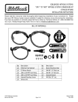
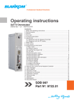
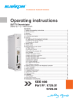
EDELBROCK NITROUS SYSTEMS
“WET” TO “DRY” NITROUS SYSTEM CONVERSION KIT
CATALOG #71884
INSTALLATION INSTRUCTIONS
Please read this instruction sheet thoroughly before beginning installation of your conversion kit. Please
have your DRY Nitrous System manual available if needed for reference at any time during this installation.
If you have any questions or comments, please feel free to contact our Technical Hotline at: 1-800-416-8628 from
7a.m.-5p.m., Monday through Friday, Pacific Time or e-mail us at [email protected].
PLEASE complete and mail your warranty card. Be sure to write the model number of this product in the "Part #____"
space. THANK YOU.
BILL OF MATERIALS
Qty.
❑1
❑1
❑1
❑1
❑4
❑2
❑1
❑5
❑1
©2005 Edelbrock Corporation
Brochure #63-0434
Description
Performer Nitrous Solenoid
Dry Nitrous Nozzle
50PSI Adjustable Hobbs Switch
1/8”NPT Brass Nipple
Solenoid Mounting Screws
Various Jets
4AN - 1/8”NPT Filter Fitting
Ratchet Hose Clamps
EFI Vacuum Tee
Qty.
❑1
❑1
❑1
❑1
❑1
❑1
❑ 3ft
❑1
❑3
Page 1 of 4
Description
Nozzle Mounting Collar
1/8”NPT Pipe Plug
90° 4AN Swivel Adapter
EFI Solenoid Bracket
Solenoid Tee
1/8”NPT Hose Barb
3/16” Hose
Nitrous Pressure Regulator
Ring Terminals
Catalog #71884
Rev. 12/05 - DC/mc
INSTALLATION INSTRUCTIONS
WET COMPONENTS INSTALLATION
WARNING!!!
Before performing any of these steps, turn off
the bottle valve and purge the nitrous system of
pressure as well as disconnect the battery.
Failure to do so may cause engine damage
and/or personal injury.
DRY COMPONENTS REMOVAL
1. Remove the 3AN nitrous line and 3AN fuel line
currently installed leading from the solenoids to the
wet nitrous nozzle.
2. Remove the wet nitrous nozzle and installed jets
from the nozzle collar. Leave the nozzle collar in
place, but plug using the supplied 1/8” NPT Pipe
Plug. Be sure to use Teflon Paste on the threads of
the pipe plug.
3. Disconnect the 4AN feed line from the nitrous
solenoid. Leave the line in place since this line will
be used for the dry system as well.
4. Disconnect the positive solenoid wires from the blue
wire coming from the relay wiring harness.
5. Disconnect the ground wires from the solenoids.
Make sure that you do not damage the ring terminal
on the nitrous solenoid because this ground will be
re-used when the solenoid is re-installed.
6. Disconnect the fuel solenoid supply hose from
wherever the hose was connected (Usually the test
port on the fuel rail).
7. Install the Fuel Pressure Safety Switch (Hobbs
Switch) in the fitting or port where your wet nitrous
system was getting fuel from (The port or fitting
referred to in step 6).
7. Remove the nitrous and fuel solenoids and brackets
from the engine compartment.
Be sure to ALWAYS use Teflon Paste, not Teflon Tape,
on ALL pipe threads unless directed not to.
1. Using a 7/16” drill bit, drill a hole in the intake boot
next to where the wet nozzle collar is mounted. This
new hole will be where you install the dry nozzle
collar. Once the hole is drilled, be sure to clean out
any shavings, and install the new nut and collar in this
hole. Note the taper in the collar and be sure to install
with this taper facing into the intake boot so the nozzle
can be installed correctly. Tighten the nut onto the
collar securely and then install the dry nozzle into the
collar. Tighten securely, making sure that the nozzle
outlet is facing into the intake manifold.
2. Take the Performer Nitrous Solenoid you are going to
re-use and remove the outlet fitting. Install the steel
tee fitting into the outlet of the solenoid, with the tee
female port facing down.
3. Install the blue 3AN to 1/8” NPT fitting you just
removed into the OUTLET side of the NEW Performer
Nitrous Solenoid.
4. Install the remaining male port of the tee of the
solenoid assembly into the inlet port of the NEW
Performer Nitrous Solenoid.
5. Install the 1/8” NPT nipple into the female port of the
tee of the solenoid assembly.
6. Install the Nitrous Pressure Regulator onto the
1/8” NPT nipple.
7. Install the 1/8” NPT to Barb fitting into the side port of
the Nitrous Pressure Regulator.
8. Install the EFI solenoid bracket to the solenoid
assembly using the supplied solenoid mounting
screws.
This concludes the removal and disassembly of the wet
nitrous system. From this point on, we will be installing
components for the dry nitrous system. This includes
using both the new components that are supplied with
this kit, as well as re-using certain components that
were supplied with your wet nitrous system such as the
nitrous solenoid and the previous nitrous system wiring.
©2005 Edelbrock Corporation
Brochure #63-0434
Page 2 of 4
The assembly
should now look
like what is
pictured here.
Catalog #71884
Rev. 12/05 - DC/mc
9. Find a secure location to mount the Performer
Nitrous Solenoid assembly within reach of the
nitrous feed line and the dry nitrous nozzle. Make
sure that this location is away from moving objects
and will not interfere with closure of the hood.
10. Connect the nitrous feed line to the INLET fitting of
the Performer Nitrous Solenoid. DO NOT use any
thread sealant, since AN fittings are designed as
dry seal fittings.
11. Using your existing blue 3AN line, connect one end
of the line to the OUTLET fitting on the Performer
Nitrous Solenoid.
12. Place the .032” nitrous jet in the EFI nitrous nozzle.
Attached the free end of the blue 3AN line to this
fitting with the jet in place. DO NOT use any type
of thread sealant for this connection.
13. Take the new EFI Vacuum Tee that is supplied with
this kit, and make sure that the .042” jet is installed.
14. Remove the vacuum line from the vehicles fuel
pressure regulator. Install this line on the center
barb of the EFI Vacuum Tee. (NOTE: The center barb
can easily be identified by the anodized nut used to
hold the Fuel Jet.)
15. Measure the correct length of vacuum line from the
barb on the Fuel Pressure Regulator to one port of
the EFI Vacuum Tee. Cut the vacuum line and
install.
16. Measure the correct length of vacuum line from the
barb fitting to the nitrous pressure regulator to the
remaining open port of the EFI vacuum tee. Cut
vacuum line and install.
This concludes the installation of the hardware for your
Dry Nitrous System. After performing these steps, it is
time to do a pressure check on all of the components
that you just installed before completing the system
wiring.
You should check the nitrous system. This should be
checked with the engine OFF. Make sure that all fittings
are tight. Slowly open the bottle valve and walk back
around to the engine compartment. Listen carefully for
leaks. Leaks can be noticed by a slight hissing sound or
by ice forming around fittings. You should hear no
sounds coming from fittings or lines if everything is
connected properly. If leaks are noticed, tighten the
fittings until the leaks seal.
©2005 Edelbrock Corporation
Brochure #63-0434
FINAL WIRING
1. Connect one wire from each solenoid to the BLUE wire
routed from the relay wiring harness.
2. Ground the inlet solenoid (the nitrous solenoid that the
feed line leads into) directly to a chassis ground.
3. Connect the remaining wire from the outlet solenoid
(the nitrous solenoid that feeds the nozzle) to the fuel
pressure safety switch.
4. Connect a wire from the remaining terminal of the fuel
pressure safety switch to a chassis ground.
Your Wiring Should Look Like This..
Fuel Pressure
Safety Switch
Ground
Second
Nitrous
Solenoid
First
Nitrous
Solenoid
To BLUE
wire from
harness
Ground
The purpose of the Fuel Pressure Safety Switch is to
prevent the safety solenoid (second solenoid in line) from
opening and filling the manifold with nitrous without
adequate fuel pressure. This switch monitors the fuel
pressure and only actuates over a pre-set fuel pressure.
To test the wiring of your Performer Nitrous Solenoids,
make sure that the bottle valve is in the “OFF” position.
Turn the ignition key to the “ACC.” position. Use a jumper
to connect the two terminals of the fuel pressure safety
switch, therby bypassing the fuel pressure safety switch.
With the arming switch in the “ON” position, quickly tap
the microswitch button to activate the system. You should
hear the first solenoid “click” if wired correctly. Make sure
that you perform this test with the valve OFF to prevent
filling the manifold with Nitrous Oxide. Be sure to remove
the jumper from the fuel pressure safety switch once done
testing the wiring.
Page 3 of 4
Catalog #71884
Rev. 12/05 - DC/mc
JET MAP INFORMATION
Edelbrock Engineering has conducted extensive dyno
testing with the Edelbrock Dry Nitrous System on various
vehicles to ensure the horsepower increase with the
nitrous system is safe and functions as intended. On a
typically stock 1.5L to 2.0L, you can expect the following
approximate horsepower gain:
Nitrous Jetting
.032
Fuel Jetting
.042
Approx. HP Gains
50hp
NOTE: This jet map is intended to be used on a
vehicle running approximately 40 psi fuel
pressure.
On an engine of greater displacement, horsepower gains
may be slightly different.
ENGINE OPERATIONS CONSIDERATIONS:
When used correctly, nitrous oxide safely elevates
cylinder pressures and temperatures while increasing
combustion rate. These characteristics make the engine
more sensitive to detonation. To ensure proper
performance, engine and drive line life, the following tips
are suggested:
System Jetting
Never exceed the recommended jetting!
jetting can result in sever engine damage.
Excessive
Fuel Quality
Because Nitrous Oxide is an oxidizer, fuel selection is
critical. Both octane and fuel consistency affect fuel burn
rate. The oxidizer quality of Nitrous Oxide will accelerate
the burn rate, so we recommend a high quality of gasoline.
We also recommend you use the same grade of gasoline
every time you use your Nitrous Oxide system. This will
help to maintain the same fuel burn rate every time.
Ignition Components
Most aftermarket performance chips increase the vehicle’s
ignition timing, which can cause detonation with the use of
Nitrous Oxide. Please consult with your chip manufacturer
on information regarding the compatibility of your chip
with Nitrous Oxide use. Many power programmers
function using the same method. Contact your power
programmer manufacturer concerning the use of Nitrous
Oxide as well. Many power programmer manufacturers
have specific programs for Nitrous Oxide use.
If your vehicle is equipped with platinum type spark plugs,
we highly recommend they be removed and replaced with
the equivalent stardard-type spark plug.
Engine System Upgrades
With all performance modifications, complementary
system upgrades will always serve to elevate the
consistency and longevity of an engine, especially when
using Nitrous Oxide as a power adder. Modifications such
as ignition upgrades, free-flowing exhaust, camshafts,
cylinder heads, and manifolds can all add to the
performance of a Nitrous Oxide injected engine.
Edelbrock Corporation • 2700 California St. • Torrance, CA 90503
Tech-Line: 800-416-8628
E-Mail: [email protected]
©2005 Edelbrock Corporation
Brochure #63-0434
Page 4 of 4
Catalog #71884
Rev. 12/05 - DC/mc