1
THE WELD MONITORING SPECIALISTS
WeldWise 2400
TM
User’s Manual
Revision C.001
Disclaimer
Livingston & Company makes no warranty of any kind with regard to this material, including, but not
limited to, implied warranties of merchantability and fitness for a particular purpose.
Livingston & Company shall not be liable for errors contained herein or for incidental consequential
damages in connection with the furnishing, performance or use of this material.
Copyright
This document contains proprietary information that is protected by copyright. All rights are reserved.
No part of this document may be photocopied, reproduced or translated to another language without
the prior written consent of Livingston & Company. The information contained in this document is
subject to change without notice.
© 2007 Livingston & Company
All rights reserved.
0453-INS-400 Rev. F
i
Product Road Map
The Livingston User's Manual includes the following sections:
•
Overview of Resistance Welding: Explains the fundamentals of resistance welding and factors
that affect the quality of resistance welds
•
Introduction to Resistance Weld Monitoring: Explains the fundamentals of resistance weld
monitoring and reasons for weld monitoring
•
Tolerancing & Monitoring: Describes Livingston's concept of resistance weld monitoring and
terminology used regarding Livingston equipment
•
Getting Familiar With the WeldWise™ 2400: A brief physical overview of navigating with the
software
•
WMS Quick Start: A basic how-to guide to weld monitoring with Livingston equipment
•
WMS Reference Guide: A complete software reference to the Livingston Weld Monitoring
Software (WMS) program
•
Installing the Sensors: Describes the various types of sensors available for use with Livingston
weld monitors and installation guidelines
•
Calibrating the Sensors: Explains how to calibrate sensors using the WMS program
•
FAQ: Includes answers to frequently asked questions
•
Troubleshooting Guide: A beginner's guide to basic troubleshooting for Livingston systems
•
Appendices: Includes information reprinted from the RWMA, and various subject matter
pertaining to both Livingston equipment and software.
•
Application Notes: Includes general 'how-to' procedures and notes relating to software and/or
hardware issues
•
Contact Information: How to reach Livingston
ii
0452-INS-400 Rev. C
Table of Contents
OVERVIEW OF RESISTANCE WELDING
1
INTRODUCTION
VARIABLES IN THE WELDING PROCESS
THE WELD CYCLE
CRITICAL FACTORS IN WELDING
1-1
1-2
1-2
1-3
CURRENT
VOLTAGE
POWER
RESISTANCE
ELECTRODES
SURFACE CONTACT
CURRENT DENSITY
1-3
1-3
1-4
1-4
1-4
1-6
1-6
OHM'S LAW AND JOULE'S LAWS
IDENTIFYING AND CORRECTING WELD PROBLEMS
RECOMMENDATIONS FOR PRODUCING QUALITY WELDS
AVOID THESE POTENTIAL SOURCES OF WELD PROBLEMS
1-7
1-8
1-9
1-10
INTRODUCTION TO RESISTANCE WELD MONITORING
2
INTRODUCTION
WHY MONITOR?
WELD LOBES AND THE WELD PROCESS
STYLES OF MONITORING
2-1
2-1
2-2
2-2
BEFORE & AFTER MONITORING
MASS MONITORING
DYNAMIC MONITORING
2-2
2-3
2-3
EFFECTS OF DIFFERENT FACTORS
HOW MONITORS WORK
MORE BENEFITS
2-4
2-5
2-5
TOLERANCING AND MONITORING
3
INTRODUCTION
LIVINGSTON WELDWISE MONITOR
SIGNATURES & MASTERS
TOLERANCES
MEASURED PARAMETERS
SEGMENTS
DATA COLLECTION
3-1
3-1
3-1
3-2
3-3
3-3
3-4
0427-INS-400 Rev. D
iii
GETTING FAMILIAR WITH THE
WELDWISE™ 2400
4
THE FRONT PANEL
WMS NAVIGATION AND EDITING
4-1
4-2
NAVIGATION
EDITING
OTHER BUTTONS
4-2
4-2
4-3
THE BACK PANEL
PROPER SHUTDOWN PROCEDURE
4-4
4-5
WMS QUICK START GUIDE
5
GENERAL SETUP
GATHERING DATA
CREATING A MASTER
ACCEPTING / REJECTING WELDS
TOLERANCING
SUMMARY
5-1
5-2
5-7
5-8
5-10
5-11
WMS REFERENCE GUIDE
6
MAIN PROGRAM SCREEN
MAIN MENU OPTIONS
DATA MENU OPTIONS
HALFCYCLE SUMMARY SCREEN
WELD SUMMARY SCREEN
SYSTEM LOG SCREEN
DATABASE MANAGEMENT
DATABASE IMPORT SCREEN
DATABASE EXPORT SCREEN
SCOPE DATA SCREEN
MASTERING SCREEN
EDIT MASTER SCREEN
TOLERANCING SCREEN
SETUP MENU
GENERAL SETUP
SETUP UTILITIES
INPUT MONITOR
TOROID SETTINGS UTILITY
VOLTAGE CALIBRATION UTILITY
FORCE CALIBRATION UTILITY
DISPLACEMENT CALIBRATION UTILITY
TOLERANCE DEFAULTS SETUP
6-1
6-4
6-5
6-6
6-11
6-12
6-13
6-16
6-18
6-20
6-21
6-24
6-25
6-30
6-31
6-38
6-39
6-40
6-41
6-42
6-43
6-44
iv
0427-INS-400 Rev. D
GRAPH SETUP
SHUTDOWN MENU
6-45
6-46
INSTALLING THE SENSORS
7
TYPES OF SENSORS
7-2
CURRENT
VOLTAGE
FORCE
DISPLACEMENT
7-2
7-2
7-2
7-3
INSTALLING THE CURRENT TOROID
INSTALLING THE VOLTAGE LEADS
INSTALLING THE FORCE SENSOR
INSTALLING THE DISPLACEMENT SENSOR
TESTING SENSOR INSTALLATION
7-4
7-5
7-6
7-7
7-8
CALIBRATING THE SENSORS
8
IMPORTANT NOTES
FREQUENCY OF CALIBRATION
THE INPUT MONITOR
INSTALLING/SWAPPING TOROIDS
PERCENTAGE ADJUSTMENT
CALIBRATING DISPLACEMENT
ZEROING THE DISPLACEMENT
CALIBRATING FORCE
CALIBRATING VOLTAGE
8-1
8-1
8-2
8-3
8-4
8-5
8-5
8-6
8-8
FREQUENTLY ASKED QUESTIONS
9
TROUBLESHOOTING GUIDE
10
APPENDICES
11
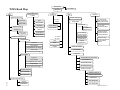
WMS ROAD MAP
RECOMMENDED DATABASE MANAGEMENT
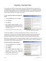
IMPORTING/EXPORTING TABLES
DISPLACEMENT CHANNEL OVERVIEW
SENSOR CALIBRATION UTILITIES OVERVIEW
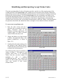
IDENTIFYING AND INTERPRETING STATUS CODES
ATTACHING PERIPHERALS
INTERLOCK INTERFACE
BINARY SELECT & ACCEPT/REJECT TIMING
WELDWISE™ 2400 SPECIFICATIONS
11-1
11-2
11-8
11-10
11-11
11-12
11-14
11-18
11-19
11-20
0427-INS-400 Rev. D
v
COMMON USES OF RWMA MATERIAL
WARRANTY & REPAIR POLICY
11-21
11-23
APPLICATION NOTES
12
APP NOTE 118 – Changing WeldWise™ 2400 Identification and IP address
APP NOTE 121 – Copy weld data and use it to create an MS Excel chart
APP NOTE 307 – Replacing a Pod
12-1
12-7
12-21
CONTACT INFORMATION
13
vi
0427-INS-400 Rev. D
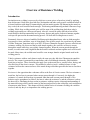
Overview of Resistance Welding
Introduction
In simplest terms, welding is a process by which two or more pieces of metal are joined by applying
heat and pressure. Back in the good old days, blacksmiths and other crafty people would heat metals in
a furnace and then weld them by hammering the red-hot metals together. By hammering the metals as
they cooled, the weld would be made stronger. This heating-and-hammering method is known as forge
welding. While forge welding worked quite well for most of the welding done back then, today's
welding requirements are a bit more advanced. After all, it would be pretty difficult to heat all the
metal needed to build an automobile in a big factory furnace and expect workers to hammer together
each specific part used in the manufacturing process. We'd all still be riding horses to work!
Fortunately, there are always a handful of brilliant people throughout history who are kind enough to
invent newer, faster, and better ways of doing things. One of these people was a professor by the name
of Elihu Thompson. Sometime in the year 1885, Professor Thompson invented a process called electric
resistance welding. He discovered that to weld metals together, one could fire an electric current
through the metals while they were tightly clamped together. When the current passed through the
metals, it would create such a high heat that the metals would melt and run together and a weld would
be made. Many times, the welded metal would be even stronger than the original metals used in the
welding process.
Today's resistance welders work almost exactly the same way they did when Thompson invented the
process. The current is generated by a transformer, and is fired through electrodes, which hold the
metal pieces in place. These electrodes also apply force to the metal pieces, usually before, during, and
after the firing of the electric current. This method is called resistance welding because it is the
resistance between the contact surfaces of the metals being welded that generates the heat to fuse them
together.
Resistance is the opposition that a substance offers to the flow of electric current. The less resistance a
metal has, the less heat is generated when current passes through it. Conversely, the higher the
resistance of a metal, the more heat is generated when that same current passes through it. This
behavior can be paraphrased as follows: the heat is where the resistance is, and the resistance is where
the heat will be. Obtaining the best results in resistance welding requires a thorough understanding of
the materials being welded, careful control of the heat and pressure at the weld point, and consideration
of numerous other factors. This chapter will deal with the basics of resistance welding, the variables
involved, and why they're so important to the welding process.
0428-INS-400 Rev. E
1- 1
Variables in the Welding Process
The many variables involved in welding can be broadly categorized into two basic sections: process
variables and material variables.
Process variables include:
Material variables include:
•
Weld current
•
Coating thickness and type
•
Squeeze time
•
Part fit-up
•
Weld time
•
•
Hold time
Surface condition & cleanliness of
materials
•
Electrode force
•
Design of the electrode
•
Workpiece material
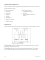
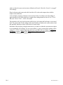
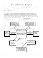
The Weld Cycle
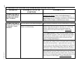
A typical resistance weld is broken down into several distinct periods, as shown in figure 1-1 below:
Figure 1-1 A typical weld cycle
The Squeeze Time is when the weld heads (electrodes) come together and build up to a specified
amount of force before the current is fired.
The Weld Time is when the current is actually passing through the workpieces. This is when the
metals are being heated enough to melt and fuse together to form what is called a weld nugget.
1-2
0428-INS-400 Rev. E
During the Hold Time, electrode force is still applied, even after the weld current has ceased. During
this period, the weld nugget cools and the metals are forged under the force of the electrodes. The
continuing electrode force helps keep the weld intact until it solidifies, cools, and the weld nugget
reaches its maximum strength.
Critical Factors in Welding
Understanding the resistance weld process requires an understanding of the main factors involved and
how they work together. This section will review current, voltage, resistance, and power, as well as the
various functions of the electrodes and how they affect surface contact and current density.
Current
Current, usually measured in Kilo-Amperes (KA — one Kilo-Amp is equal to 1,000 Amps), is one of
the most important factors. A resistance weld cannot be made unless there is sufficient weld current.
According to the RWMA, the typical amount of current needed to weld low-carbon steel, for example,
is about 10,000 Amps (10 KA) at about 5 Volts. To put this in perspective, a normal household or
office outlet provides a maximum of 15-20 Amps (0.015-0.020 KA) at 120 Volts, while a power
circuit in a factory may only be capable of providing 200 Amps (0.200 KA) at 500 Volts to a welder.
The factory's 200 Amps is then converted to the 10,000 Amps needed to weld by means of a welding
transformer.
A transformer consists of two coils of wire, called the primary and the secondary, wound around an
iron core. Power is transferred from primary to secondary via the magnetic properties of the iron. The
factor by which the current and voltage is stepped up or down is equal to the ratio between the number
of turns of wire in the coils forming the primary and secondary windings of the transformer. Consider
the steel that needs 10,000 Amps (10 KA) of current to be welded in a factory that can only provide
200 Amps (0.200 KA). If the welding transformer had 100 turns on the primary and 2 turns on the
secondary, the 'turns ratio' would be 100 to 2, or more simply, 50 to 1. The 200 Amp current in the
primary would then be converted (stepped up) to 10,000 Amps (200 Amps x 50 turns = 10,000 Amps)
in the secondary, which would yield enough amperage to make a weld.
Voltage
If current is the amount of electricity flowing, then Voltage (measured in Volts) is the pressure or force
that's causing the flow. A good analogy is water flowing through a pipe. A larger voltage will result in
greater water pressure, which will cause more water (current) to flow through the pipe. Using the
transformer example above, after the 200 Amps at 500 Volts on the primary passes through the
transformer coils, the secondary amperage increases to 10,000 Amps, but the voltage actually drops to
10 Volts. This decrease in voltage occurs because the amount of power coming out of a transformer
isn't actually increased, but more accurately exchanged.
0428-INS-400 Rev. E
1- 3
Power
Power is Voltage multiplied by Current, and is measured in Watts, or KVA (KVA stands for KiloVolt-Amperes. Watts and KVA will be used interchangeably in this text). This means that the amount
of current flowing times the pressure that's causing it to flow equals the amount of power generated. A
basic law to bear in mind is that the power going into a transformer will always equal the power
coming out of it. Returning to the transformer example, 200 Amps coming in at 500 Volts (200 x 500
= 100,000 KVA) on the primary with a 50 to 1 turns ratio in the transformer will be converted into
10,000 Amps at 10 Volts (10,000 x 10 = 100,000 KVA) going out. As the math illustrates, the results
are the same. The initial and final amperage and voltage may be different, but because the ratio is the
same, the total amount of power is also the same.
Resistance
As mentioned earlier, resistance is defined as the opposition that a substance offers to the flow of
electric current. Resistance is calculated by dividing the Voltage by the Current, and is measured in
Ohms. (When written, Ohms are represented by the Greek letter Omega: Ω). Since resistance to the
current is what generates the heat in the workpiece, it is critically important that the area with the
greatest resistance be at the interface between the two parts being joined. This interface is also known
as the faying surfaces. Remember that the heat is where the resistance is, and the resistance is where
the heat will be. If the area with the most resistance is, for example, where the lower bus bar connects
to the transformer of the welder and not at the faying surfaces of the workpieces, then that's where the
heat will go. Likewise, if the greatest resistance is at the contact area between the electrode tip and the
workpiece, the heat generated there will cause the tip to weld directly to the workpiece.
Electrodes
Typically made of copper alloys, electrodes actually have three separate functions: to conduct current
to the workpieces being welded, to transmit the proper pressure or force to those workpieces to
produce and forge a good weld, and to help dissipate heat from the area being welded. To ensure that
all three of these functions are executed properly, it is important to regularly maintain the electrodes,
keeping them clean and in good condition. A reprint of an RWMA chart describing various types of
electrode materials and their different uses may be found in Chapter 11, APPENDICES, of this
manual.
Conducting Current
The first of these functions is purely electrical— fire weld current through the workpiece. Taking into
account the relationship among current, voltage and resistance, it becomes important to pay attention to
the type of electrodes used. For example, it wouldn't be wise to select electrodes made entirely from a
high resistance material, since they would get so hot they'd melt before the current even had a chance
to flow to the workpiece. It is also important to make sure that the electrodes are the right size for the
application; proper electrode sizing is largely dependent on the amount of force being used on the
workpieces.
Transmitting Force
The second function of the electrodes is mechanical. The amount of force needed to make a good weld
varies, depending on the type of metal being welded and other factors, but a general figure would be
about 600-800 lbs. Because electrodes are typically on the small side— roughly from about the size of
1-4
0428-INS-400 Rev. E
an acorn to the size of a plum, it is also important to choose electrodes that are able to withstand the
force needed to make a good weld.
A key point to understand is that force and resistance have an inverse relationship: more force will
result in less resistance, and vice-versa. The equation has to do with surface contact, which refers to the
specific area on the workpieces touched by the electrodes. Surface contact will be covered further in
the next section, but the following example will begin to illustrate this relationship: if you examine
your fingertip under a magnifying glass, what first appears to be a smooth surface is actually a mass of
rough-looking ridges and bumps. The same is true of electrodes and workpieces. The tips of the
electrodes and the surfaces of the workpieces may look to be smooth and in good condition, but in
reality their surfaces are quite rough, especially if the electrodes are old and worn or if the workpieces
are dirty. By applying pressure to these rough surfaces, any microscopic inconsistencies (e.g., dirt or
grease on the workpiece and/or pits and cracks in the electrodes) are compressed and the surface
actually evens out. This results in improved (increased) surface contact between the electrode tips and
the workpiece, and between the workpieces themselves. When the surface contact is increased, current
can flow more readily from the tips through the workpieces, which means that the resistance has been
lowered.
Force also is what helps to keep the weld intact as it's being formed. As the current generates heat, the
workpiece metal begins to melt. A good analogy to this process is a child eating a popsicle on a hot
summer day. When the popsicle melts, it doesn't remain on the stick― it drips everywhere. When
metal melts it wants to do the same thing, however because it's molten metal and not a runny popsicle,
it doesn't simply drip. It explodes out of the workpiece. This is why proper weld force is so important:
it literally forces the molten metal to stay put, so it can then cool to form a weld nugget. Without
sufficient force, the metal will do what it wants to do, which is what causes expulsion. Expulsion is
nothing more than little pieces of molten metal exploding out of the weld because they're not being
properly held in. The problem with expulsion is that all the metal flying out of the weld is metal that's
not going in to the weld; a weld cannot be made stronger by removing metal from it. Determining the
proper amount of force is entirely application dependent. The RMWA can be contacted for additional
recommendations and guidelines.
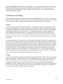
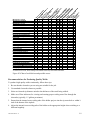
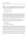
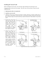
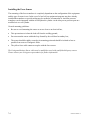
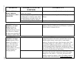
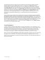
Cooling the Workpiece
Electrodes get considerably hot with 10-20 KA or
more repeatedly flowing under hundreds of pounds
of force. Although most welders have an internal
water cooling system that allows water to circulate
through the tips of the electrodes while welds are
being made, a common problem is a lost, damaged or
improperly sized cooling water tube. Without
anything to cool off the tips, heat can quickly build
up to the point where the electrodes will eventually
weld to the workpieces. To correct this problem, the
water tube should be placed so that the incoming
cold water strikes the hottest part of the tip first, as
shown in figure 1-2.
Figure 1-2 Example of an electrode cooling
channel.
0428-INS-400 Rev. E
1- 5
Surface Contact
The ultimate goal of the weld process is for the weld current to generate sufficient heat between the
workpieces being welded so that the metal will melt, fuse together and form a weld nugget. For this to
happen, the surface contact must be maximized. The following experiment may sound silly, but proves
an important point: take a piece of Scotch tape and stick it to a clean piece of paper. Assuming that the
tape was clean beforehand, it probably sticks very well. Now sprinkle some salt on the piece of paper.
Stick another piece of tape to the paper with the salt on it. Depending on how much salt is there, the
tape probably sticks somewhat to not at all. Lastly, stick a third piece of tape to some carpeting, then
pull it off. Now try to stick that same tape to the paper. The third piece probably doesn't stick at all.
Compare the electrodes to the tape and the workpiece to the paper. The clean tape sticks best to the
clean paper, just like well-maintained, clean electrodes have the best contact with a clean workpiece.
The tape sticks so-so to the paper with the salt on it, just like electrodes will have a so-so contact with
the workpiece if it's dirty, greasy, etc. Lastly, the tape that has been stuck to the carpet and then restuck to the paper probably doesn't stick well at all, just like worn or pitted electrodes don't have very
good contact with the workpiece. By maximizing the surface contact, current density is increased. Both
of these factors play key roles in ensuring that enough heat is generated to reach that ultimate goal of
forming a weld nugget.
Current Density
Current density describes how much current is being delivered to a specific area. In other words, it
describes the concentration of the current in a small area of the workpiece— namely, the area where
the weld is. To calculate current density, the amperage (how much current) is divided by the surface
area (area of contact between the electrode and the workpiece). As a rule, the smaller the surface area,
the denser the current. When the current is denser, the surface area gets hotter and the metal melts
faster. Consequently, a current density that is too high for the application may cause expulsion. In
contrast, a larger surface area delivers a less dense current. If the current density is too low for the
application, there may be cold welds or perhaps no welds at all.
The size, shape and overall condition of the electrodes affect the surface area in contact. Small pieces
missing from the tips of the electrodes (pitting) will result in an increased current density due to the
decreased surface area. The same amount of current fired through a smaller surface area may cause
little hot spots that expel molten metal (expulsion), and/or may result in undersized weld nuggets.
Conversely, if the electrode tips mushroom and get bigger, the current density is lower. For example,
suppose that there are 6-mm round tips on a welder. The area of each tip is about 28 mm2. (The area of
a circle is πr2: 32*3.14 ≈ 28). Suppose the tips deliver 10 KA to a workpiece. Current density equals the
amperage divided by the surface area, so the current density will be 0.36 KA, or 36 Amps for every
millimeter squared of surface (10 KA/28 mm2 = 0.36 KA/mm2). What happens if the tips mushroom to
measure 7-mm (about 0.040 inches greater in diameter)? Although one millimeter doesn't seem like a
significant increase, consider what happens to the current density: The 7-mm tips now have a surface
area of about 38 mm2 (3.52*3.14 ≈ 38). Dividing the amperage by the surface area results in 0.26 KA
or 26 Amps for every millimeter squared of surface. The difference between 36 Amps per mm2 and 26
Amps per mm2 is a rather significant 28% reduction in current density! (36 Amps – 26 Amps = 10
Amps difference; 10 Amps is 27.78% of 36 Amps).
By allowing the electrodes to mushroom only one millimeter bigger, over a quarter of the current
density has been lost, even though the same amount of current is passing through the tips. Imagine the
1-6
0428-INS-400 Rev. E
size of the loss if they've mushroomed 2, 3, even 4 millimeters! A constant current control or a weld
stepper may be used to regulate the amount of current used, but a controller or stepper does not track
the change in surface area. So, even though the current is regulated, the current density is overlooked.
Unfortunately, inadequate current density usually produces inadequate welds. Following proper
preventive maintenance schedules can help ensure sufficient current density by ensuring that the
electrodes remain in good condition.
As proven in the example above, it is crucial to have the proper current density at the area where the
weld is to be made. Depending on the materials being welded, however, 'proper' current density is
actually a range, rather than one specific amount. Welding engineers call this range the weld lobe. Each
parameter involved in making the weld (current, voltage, resistance, etc.) has its own range, or lobe.
Quality welds are made when the weld process stays within the lobe. The next chapter will discuss
weld lobes and tolerancing, which is a way to ensure that the weld process does not fall outside of the
lobe.
Ohm's Law and Joule's Laws
The following laws are widely thought to be what make or break resistance welding. While it is true
that these laws are very important to resistance welding, there are a few details that should be clarified.
Ohm's Law states that V (Voltage) = I (Current) x R (Resistance).
What does this mean in real-world terms? Returning to the pipe example, the more water pressure
there is in a pipe (more voltage), the more water can flow through that pipe (more current). If the size
of the pipe decreases (more resistance), then the water flow will decrease (less current) but the pressure
drop along the pipe will increase (more voltage).
Joule's Law states that H (Heat) = I (Current) x V (Voltage) x T (Time the current is allowed to flow).
Or, written differently,
H (Heat) = I2 (Current squared) x R (Resistance) x T (Time the current is allowed to flow).
Note: V (Voltage) = I (Current) x R (Resistance), so the two equations are the same, just stated
differently. The second version of this law is probably more common in the field.
Joule’s Law is an equation that gives the amount of heat (energy) delivered to something. It would
seem sensible to assume that it's the amount of heat delivered to the weld. However, it is important to
consider all the factors in the equation: Current, Voltage, and Time. Joule's Law assumes that each of
these factors remains constant in the secondary of the welding transformer. A weld controller or weld
timer may indeed provide a constant amount of current at the electrodes, but recall Ohm's Law:
Voltage equals Current times Resistance, or written differently, Current equals Voltage divided by
Resistance. Factors like pitting or mushrooming of the electrodes, dirty workpieces, changes in force,
etc. all have an effect on the surface area (the area of contact) between the electrode and the workpiece.
Since changes in the surface area affect the contact resistance (resistance of the surface area), it is
reasonable to say that the resistance at the workpiece is not constant, but rather a factor that can change
depending on a number of other conditions. If Resistance is not constant, then according to Ohm's
0428-INS-400 Rev. E
1- 7
Law, Current is not constant either. This means that the I-squared version Joule's Law will not reveal
the amount of heat generated at the workpiece unless the resistance at the tips is known.
Simply put, to determine how much heat is being generated at the workpiece using Joule’s Law,
current, voltage or resistance must be measured at the workpiece. Although a weld controller may be
programmed to deliver 20 KA at 10 Volts, if there is significant resistance in the secondary weld loop,
the heat will go there and not to the workpiece. Likewise, if the electrodes are worn or the workpiece is
dirty, resistance and current density will be affected. In such a situation, a controller might indicate 10
Volts at the secondary, however there might actually be only 5 Volts at the weld tips. Such a disparity
could easily cause bad welds.
Identifying and Correcting Weld Problems
A simple rule to remember is that quality usually equals consistency: welds that are always made
within the specified weld lobe will consistently be of high quality. The question is, how can you
determine if welds are being made consistently within the lobe? If a weld control is programmed to
deliver a certain amount of current at a certain amount of force, how can you ensure that the right
amount of current and force was delivered at the tips? The amount of current coming out of the
transformer may be correct, but is the current density at the workpiece where it should be? How do you
know if the weld is good? The most common method of answering these questions is through
destructive testing. It's hard to dispute the quality of a weld after it has been pulled apart and inspected.
However, destructive testing produces a lot of scrap metal, and while it will reveal whether the weld is
good or bad, it cannot explain the specific details of why or how a weld turned out the way it did.
Resistance weld monitoring provides a way to see what is happening while each weld is being made.
Critical parameters, such as resistance and current density, can be observed and measured at the
workpiece during the weld process. The next chapter will discuss how this process works.
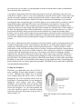
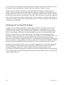
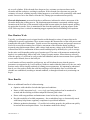
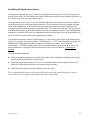
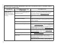
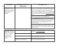
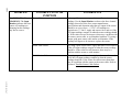
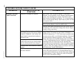
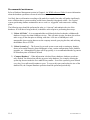
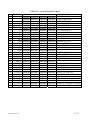
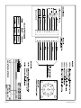
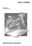
The following is an abbreviated guide of commonly encountered welding problems and their possible
causes, adapted from documents published by the Resistance Welder Manufacturers' Association and
reprinted with permission.
1-8
0428-INS-400 Rev. E
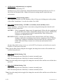
Ex
ce
s
El s In
ec
de
n
M tro
us de tat
io
hr
n
oo
U
m
nd
in
g
N ers
ug iz
ge ed
W
t
O
el
ffs
d
et
W
M
el
is
d
s
N
N ha
ug
ug p
e
ge
ge n
W
t
Ex t
el
d
pl
us
Ex ion
pu
at
ls
io Su
C
r
n
ra
at fac
c
e
N ke
In
ug d
te
ge or
rf
t Po ace
D
or
is
c
W
N olo
el
ug re
d
ge d
W
t
N
el
o
d
W
el
d
Weld Force Too High
Weld Current Too High
Weld Time Too Long
Weld Force Too Low
Weld Current Too Low
Weld Time Too Short
Electrode Face Too Small
Electrode Face Too Large
Insufficient Electrode Cooling
Electrode Allow Too Soft
Electrodes Not Flat & Parallel
Electrodes Misaligned
Poor Fit Up
Poor Heat Balance
Weld Spacing Too Close
Weld Too Close To Edge of Part
Dirty Material
Metallurgy of Material
Squeeze Time Too Short
Poor Follow-Up
No Speed Regulator On Cylinder
Poor Pressure Regulation
Hold Time Too Short
Transformer Tap Set To Off
No Weld Switch(es) In No Weld
Pressure Switch Open
Temperature Limit Switch Open
Electrodes Do Not Contact Work
Insulated Electrodes/Holders
Shunt Path In Secondary
Excess Ferrous Material In Throat
Emergency Stop Switch Open
X
X
X
*
X
X
X
X
X
X
X
X
X
X
X
X
X
X
X
X
X
X
X
X
X
X
X
X
X
X
X
X
X
X
X
X
X
X
X
X
X
X
X
X
X
X
X
X
X
X
X
X
X
X
X
X
X
X
X
X
X
X
X
X
X
X
X
X
X
X
X
X
X
X
X
X
X
X
* If Weld Force is too low, excess heating of the material surface may cause excess indentation.
Figure 1-3 Chart of weld defects and possible causes
Recommendations for Producing Quality Welds
To produce high quality welds consistently, follow these tips:
1. Be sure that the electrodes you are using are suitable for the job.
2. Use standard electrodes whenever possible.
3. Select an electrode tip diameter suited to the thickness of the stock being welded.
4. Make use of flow indicators for viewing and assuring proper cooling water flow through the
electrodes (typically, 1.5 gallons per minute).
5. Ensure that the internal water cooling tube of the holder projects into the tip water hole to within ¼
inch of the bottom of the tip hole.
6. Adjust the internal water-cooling tube of the holder to the appropriate height when switching to a
different length tip.
0428-INS-400 Rev. E
1- 9
7. Ensure that the top of the adjustable water-cooling tube in the holders is the proper height when
changing to a different tip length.
8. Coat the tip with a thin film of cup grease before placing it in the holder to simplify removal.
9. Use ejector type holders for easy tip removal that won't damage the tip walls.
10. Clean the tip taper and holder taper on a regular basis, removing any foreign materials.
11. Perform dressing of electrodes on a regular basis to maintain the correct contour.
12. Use a rubber mallet to align holder and tips, rather than a metallic tool.
Avoid these potential sources of weld problems:
1. Never weld using unidentified electrodes or electrode materials.
2. Avoid using special-purpose or offset tips if the job can be handled with a standard straight tip.
3. Do not use a small tip for welding heavy gauge materials or a large tip on small piece.
4. Do not overlook turning on the cooling water to the appropriate force when beginning to weld.
5. Never use a water hose that does not firmly fit the water connection nipples.
6. Avoid leaky, clogged or broken water connections.
7. Do not use holders that have leaking or deformed tapers.
8. Do not use electrode holders without an adjustable internal water cooling tube.
9. Avoid leaving the electrodes unused in tapered holder seats for long periods.
10. Do not use pipe wrenches or similar tools when removing electrodes.
11. Never dress an electrode using a coarse file.
These recommendations can help improve the quality and consistency of your welds. For more
information, you can contact the RWMA (Resistance Welding Manufacturing Alliance) or AWS
(American Welding Society) directly:
550 NW LeJeune Road
Miami, FL 33126
Tel: (800) 443-9353
Intl.: (305) 443-9353
URL: www.aws.org
1-10
0428-INS-400 Rev. E
Introduction to Resistance Weld Monitoring
Introduction
As discussed in the last chapter, what you see is not always what you get. Although a constant current
control may indicate that there is sufficient weld current to create a quality weld, unless the
measurement is taken at the electrodes, the actual amount of heat generated is only speculation. In
view of the fact that the generation of sufficient weld heat is a function of current density, it could
logically be argued that the primary cause of bad welds is inadequate current density. Many factors
affect current density: poorly maintained, worn or improperly sized electrodes, dirty materials, lack of
sufficient force at the tips and lack of sufficient weld current at the tips are just a few examples. This
being the case, how can a production person or weld engineer catch these (or other) potential problems
before they lead to bad welds? How do you make sure that what you see is what you get? The answer
lies in the subject of this chapter: resistance weld monitoring.
Why Monitor?
When Professor Elihu Thompson developed the concept of resistance welding, the idea of weld
monitoring most likely didn't exist. At that time, the only means available of differentiating a good
weld from a bad weld was through destructive testing. Even today, destructive testing is regularly used
to provide a reliable answer— 'good weld' or 'bad weld'— depending on how the weld reacts during its
destruction. For all its reliability, however, destructive testing doesn't tell the whole story. While it can
easily be determined whether a weld is good or bad, uncovering the precise factors that made it that
way is not as straightforward. Was there an excess or deficiency of one or many factors during the
weld? At what point or points in the welding process did the excess or deficiency occur? Resistance
weld monitoring can provide immediate answers to these questions.
With the advent of advanced computer technology, today's methods of observing and testing individual
weld integrity have advanced significantly, keeping in step with ever-evolving safety and quality
standards. By monitoring the welding process, compliance with international quality standards– such
as ISO and/or QS 9000+, or MVSS– is simplified. Weld quality can be instantly verified with
electronic documentation of individual weld characteristics; hard copy of weld data can even be
printed for comprehensive record keeping or for inspection. It's hard to dispute the integrity of a
product when the most critical stages in the manufacturing process have been systematically observed,
recorded and analyzed.
It's important to realize that weld monitoring is not a substitute for destructive testing. Rather,
monitoring and destructive testing go hand in hand. While destructive testing can unconditionally
guarantee whether an individual weld is good or bad, monitoring can show why that particular weld
was good or bad. Together, they can answer what is perhaps the most important question of all: is the
welding process consistently within the defined weld lobe?
0429-INS-400 Rev. C
2-1
Weld Lobes and the Weld Process
Each of the factors involved in the creation of a weld (Current, Voltage, Resistance, etc.) has a specific
range in which good welds can be made. This range is commonly known as the weld lobe. Bad welds
are made when the weld process falls outside of the lobe, so the simple answer to making consistently
good welds is to keep the process inside the lobe. It is not so simple, however, to ensure that this
happens for each weld made. This is where resistance weld monitoring is most valuable. The following
example uses a weld nut and the relative movement of the electrodes during the weld to examine what
goes on during the weld process. Livingston terminology (in italics) is used to describe various
measurements.
The nut itself has a number of little metal feet or projections on the bottom of it. These projections sit
on top of the workpiece to which they'll be welded. A measurement of the nut sitting on top of the
workpiece with the electrodes clamped on it before the weld is made is called the Initial Thickness.
When the proper electrode force is applied and weld current is fired, the projections melt into the
workpiece and create a weld. When the projections melt, the molten metal expands for a moment,
pushing the electrodes apart (this movement is called Expansion) before sinking down into the
workpiece (this movement is called Setdown). The expansion-setdown process is very much like a pot
of water boiling over before it's removed from the heat: as the metal is heated, it expands and then
quickly contracts as it cools to form the weld. A subsequent measurement of the nut/workpiece after
the weld is made is called the Final Thickness. All these different measurements of electrode
movement are measures of what's commonly called Electrode Displacement, or simply Displacement.
Measuring displacement provides a good indication of whether or not the resulting weld was formed
properly. If the nut sinks too far into the workpiece, it may be a sign of excessive heat which could
render the weld no good. It could also indicate that too much force was applied, the weld time was too
long, or a number of other things. Conversely, if the nut doesn't sink far enough, it may mean that not
enough heat was generated for the materials to weld properly, the force was insufficient, etc. Problems
with displacement can be problematic in many applications, such as welding hydraulic fittings. If the
setdown is too much/too little, chances are that the welded fitting will leak. When taken into account
that displacement is only one of many factors that, when measured, provide valuable information about
the formation of the weld and its overall quality, it becomes clear that weld monitoring is indeed a
valuable tool. Weld monitoring provides the user with an easy way to access a wealth of information
about the welding process— information that can actually help improve the process itself, as well as
alert the user to any number of potential problems.
Styles of Monitoring
There are many different types of monitoring systems on the market nowadays. These systems can be
broadly categorized into three different styles, which for educational purposes are nicknamed as
follows: Before & After monitoring, Mass monitoring, and Dynamic monitoring.
Before & After Monitoring
As the name suggests, Before & After monitoring (hereafter referred to as BA monitoring) focuses on
only two phases of the weld process: before the weld is made, and after the weld is made. This type of
monitoring is typically used to measure displacement only. As mentioned above, measuring
2
2-2
0429-INS-400 Rev. C
displacement can indicate whether the resulting weld was formed properly. BA monitoring measures
the displacement before the weld is made (Initial Thickness), and then again after the weld is made
(Final Thickness). However, if it is determined that the displacement is consistently below where it
should be (e.g., the nut is not sinking far down enough into the workpiece to make a good weld), BA
monitoring cannot identify exactly where in the process the problem is occurring. Similarly, the BA
monitor may indicate a normal setdown, yet the nut may be sinking down much too quickly due to
expulsion. While BA monitoring provides an account of the beginning and end of the weld process, the
key middle-portion of the process is unwisely overlooked.
Mass Monitoring
Mass monitoring provides a more in-depth examination of the weld process, but does it by averaging
all the measured parameters during the course of the weld. Using the weld nut from the displacement
example in the previous section, we'll examine force during the weld process. The nut and workpiece
are clamped together under pressure between the electrodes, and the weld current is fired, generating
heat and creating a weld. A Mass monitor will measure parameters during the weld process and will
provide an average for each after the weld is made. In this particular example, the monitor might
indicate that the average force during the weld was 800 lbs. Suppose, however, that subsequent
destructive testing of the part showed that the weld was bad. Why would this be the case if the monitor
indicated that the average force was appropriate?
The trouble with this type of monitoring system lies in the averaging of the parameters before a result
is presented. Recall that a typical weld cycle can be broken up into three separate sections: the preweld, weld, and post-weld segments. If the force during each of these sections was 1700, 300, and 400
lbs., respectively, the average would be 800 lbs. The end result appears acceptable, but the averaging
only serves to disguise substantial irregularities in the force during the weld process. Mass monitoring
is also relatively insensitive to changes in the weld schedule and weld current. Aspects such as
upslope and downslope are recorded, but are delivered as averages rather than by the cycle (or
halfcycle). Although the average current for a 10-cycle weld could be the same as for a 20-cycle weld,
there would probably be a great deal of expulsion in the 20-cycle weld. A Mass monitor would not be
able to detect anything amiss in this situation, because the average would likely be an acceptable
figure. While Mass monitoring is a more thorough method of observation than BA monitoring, it's still
not the most effective method of monitoring the resistance weld process.
Dynamic Monitoring
Dynamic monitoring is currently the most comprehensive method of observing and recording the weld
process. A Dynamic resistance weld monitor measures weld parameters in real-time, while the weld
process is happening. More detailed than a before/after picture, and more accurate than an average of
each parameter, a Dynamic monitor provides a complete view of the weld process as the weld is being
made, measured in either halfcycles or cycles (based on a 50 or 60 Hz sine wave). Because the weld
process is observed so closely, events such as Expansion and Setdown can be pinpointed down to the
halfcycle. If weld irregularities are suspected, recorded weld data can be analyzed to determine where
in the process they're occurring and what factors are contributing to the problem. Potential problems
can also be detected before they occur: parameters such as resistance or force can be trended to
ultimately predict electrode wear and improve preventive maintenance schedules.
0429-INS-400 Rev. C
2-3
Effects of Different Factors
Each of the four main parameters— Current, Voltage, Force, and Displacement— affect the properties
of a weld.
Current, measured in KA, is typically set and expressed as a percentage of heat on weld controls used
by a number of manufacturers, although some of the more modern equipment allows a current setting
in KA instead of a percentage. Throughout the industry, the majority of welds are performed using
single-phase AC current, but there are other sources of welding current used as well. These include:
• Single and Three-phase rectified DC
•
Mid-frequency DC (600-1,200 Hz)
•
High-frequency DC (2,000-25,000 Hz)
•
Capacitive Discharge DC
Whatever type of current is used, control of current density during welding is the most important factor
involved in making a quality weld. Without proper current density, too much heat can be generated,
leading to expulsion and/or part deformation. Conversely, there may be too little heat generated,
causing cold welds and/or incomplete weld nugget formation. Some people uphold the 'bake it longer'
theory, which prescribes lower weld heat for a longer time. While this reduces expulsion, the longer
weld time makes it much less efficient. Others think that in order to have good welds, expulsion is
necessary as an indicator that a weld is being made. However, tiny pieces of molten metal exploding
out of a weld cause the weld itself to be weaker than it would be without expulsion.
Voltage, measured in Volts, is also a key indicator during the weld process. As discussed earlier,
voltage is a relative measure in that the location of the measurement is important. The voltage in the
secondary of a welder can vary during operation due to a variety of factors, including:
•
variances in the part fit-up;
•
loose connections;
•
line load variations within the plant;
•
differences in power factor throughout the day.
Voltage variations at the tips due to worn or pitted electrodes, dirty materials, or insufficient surface
contact with the workpiece can also affect resistance and current density. As a partial solution, many of
today's controllers are equipped with an Automatic Voltage Compensation (AVC). If a voltage drop in
the factory line is detected, the control will adjust in an attempt to provide the same amount of energy
to the weld. Despite the adjustment, what comes out of the transformer is not necessarily what comes
out of the electrodes. The same conditions apply to constant current controls. Even though the amount
of current coming out of the transformer secondary is regulated, the amount at the tips may be variable.
Force, measured in pounds per square inch (psi), pounds (lbs.), or kilograms (kg), indicates the amount
of pressure being applied to the electrodes before, during and after the weld process. Electrode force is
typically provided by air, hydraulic, or spring pressure. Changes in force can result in a significant
increase or decrease in resistance as the weld is taking place. This is particularly true of welders using
2
2-4
0429-INS-400 Rev. C
air over oil cylinders. If the electrode force drops too low, resistance can increase between the
electrodes and the workpiece, resulting in expulsion. If the electrode force becomes too great, the
resistance is lowered, resulting in poorly formed nuggets or even brittle welds, particularly with coated
metals. Excessive force also reduces electrode life, causing tips to mushroom more quickly.
Electrode displacement, measured in inches or millimeters, indicates the relative movement of the
electrodes during the welding process. The displacement measurement corresponds with the nugget
formation at the weld site: as the materials being welded become molten, the metal expands, pushing
up against the electrodes. Force is maintained as the electrodes push back, applying pressure to the
weld. Follow-up force is critical in containing nugget expansion and in eliminating weld expulsion.
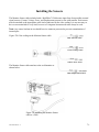
How Monitors Work
Typically, a weld monitor receives input from the welder through a variety of sensors that can be
configured for specific applications. These sensors measure the characteristics of the weld process and
transmit this data to the weld monitor. Toroids are used for measuring current, and pressure sensors or
load cells are used for measuring force. Relative movement of the electrodes during welding is
measured using displacement sensors, while voltage leads measure voltage at the weld head. Data is
collected from all or a combination of these sensors and displayed by the halfcycle, cycle or average
for the entire weld, depending on the type of monitor used. The more weld parameters monitored, the
harder it is to unknowingly make a bad weld. Using a Dynamic monitor, factors that may adversely
affect the quality of a weld can be easily tracked and identified, and the exact moment when a problem
occurs can be isolated, down to the halfcycle.
A weld monitor will not control the weld process, nor will it inform the user what the process
parameters are supposed to be. It will confirm if welds are made within the limits set by the user, and a
monitor can be used to simplify methods of refining process parameters. It's important to understand
that the user first needs to define the weld lobe and proper weld schedule. Once a weld lobe and
schedule are established (according to internal standards, or through trial-and-error), monitoring can
begin.
More Benefits
Below are additional benefits of weld monitoring:
•
Optimize weld schedules for individual parts and conditions.
•
Ensure a 100% inspection level— every single part being produced can be monitored in
seconds and the resulting weld data compared to known good values.
•
Detect weld setup problems and maintenance issues before they cause bad welds.
•
Provide traceability of welded components— the recorded hard copy or electronically stored
weld history helps ensure regulatory compliance in specialized industries.
•
Minimize production downtime— if a welder isn't working properly, the problem can quickly
be tracked down and repaired faster. Less downtime means more money!
0429-INS-400 Rev. C
2-5
Both quality improvements and efficiency can be gained through weld-process monitoring. For
example, by demonstrating and tracking the consistent high quality of primary welds, the need for
additional "safety" or "delta" welds can be reduced or even eliminated. The ability to quantify what
constitutes a known good weld makes it possible to achieve consistent results, even in high-volume
situations. Productivity gains can also be achieved by replicating and tracking those conditions that
have been shown to result in ideal welds. In a high-volume, automated factory line environment, the
resulting gain in productivity can be substantial.
2
2-6
0429-INS-400 Rev. C
Tolerancing and Monitoring
Introduction
This chapter will introduce Livingston's concept of dynamic resistance weld monitoring. The
definitions of tolerances and segments as they pertain to a WeldWise™ 2400 will be discussed, as well
as how these features allow the user to immediately identify and correct faulty parameters or
conditions that can produce poor quality welds. Different parameters that can be monitored using
Livingston equipment will be identified, in addition to some of the ways that monitoring can be used to
simplify and refine the weld process.
Livingston WeldWise™ Monitor
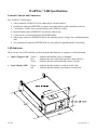
The WeldWise™ 2400 Dynamic Resistance Weld Monitor is a portable bench top unit that, when
connected to the appropriate sensors, can be used to monitor a single weld head in a fixed location or
rotated on your factory floor to monitor different weld heads, one at a time. If a weld is not within
master tolerance limits, the WeldWise 2400™ sends a reject signal to a PLC or similar controller,
which is then displayed on the monitor as a 'rejected' weld. If the weld is within tolerances, the
WeldWise 2400™ sends an accept signal, which is displayed as an 'accepted' weld.
The WeldWise™ 2400 performs real-time monitoring on a halfcycle-by-halfcycle basis for AC welds.
A 'halfcycle' is exactly what the name implies: one half of a weld cycle, based on a 50 or 60 Hz sine
wave.
Signatures and Masters
Once a Livingston weld monitor and sensors have been installed and the WMS (Weld Monitoring
Software) program is running, the monitor continually collects data from the sensors. When a weld is
made, information about that weld is captured, analyzed, displayed and stored by the monitor. This
information is called a weld signature. Simply put, a weld signature is the distinct characteristics of
any particular weld. From either one or a collection of high-quality weld signatures, a master signature
is made. Throughout this text, a master signature and its related tolerances (see below) will be referred
to simply as a master. A 'high-quality' weld signature is the signature of any production weld made that
was proven to be high quality through destructive testing. A master is a set of values representing those
conditions that make for a high-quality weld.
A master is created in the WMS program by making a high-quality production weld and using its
corresponding signature. The master is what defines the acceptable range for individual weld
parameters through tolerances, which are initially drawn from a set of default values installed when the
master is made. Once a master is created, tolerances can be individually modified by the user and
depending on the application, can be loosely or strictly defined. Once tolerances are defined for a
master, every subsequent weld made will be compared with the stored master tolerance limits. If the
weld does not fall within the master tolerance limits of that master, the monitor will record a reject
signal and display it as a rejected weld. Using a PLC, this signal can also be set to trigger a variety of
rejected-weld responses, such as lights, buzzers, and reset-reliant restrictions (the electrodes will
0430-INS-400 Rev. D
3-1
remain clamped until the ladder logic has been reset). Parts with rejected welds can then be
immediately identified and isolated from parts with accepted welds.
Selecting a Master
A Livingston weld monitor can store a number of masters (contains master tolerance limits) that are
selectable using the binary select inputs. Selecting different masters is desirable for weld heads that
make more than one weld perhaps with a different weld schedule or different part stack up. Please refer
to the General Setup Menu section in this manual for more information on binary select modes. The
WeldWise 2400 Binary Select inputs are 24V discrete connections located on the rear of the monitor.
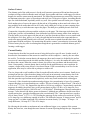
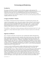
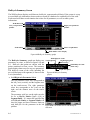
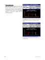
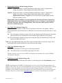
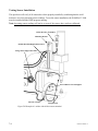
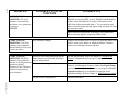
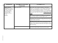
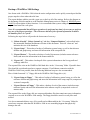
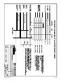
Tolerances
915
Force in Lbs.
Understanding tolerances requires an
understanding of the weld lobe. Restated
simply, a weld lobe is the range for any
welding parameter in which a highquality weld can be made. A weld lobe
is typically defined by destructively
testing welds and then examining the
corresponding weld data to determine
quality limits.
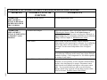
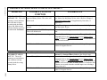
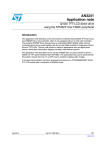
Weld Data: Current vs. Force
910
905
force
900
895
890
0
2
4
6
8
10
12
Current Rm s in KA
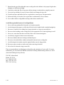
Figure 3-1 Weld data showing Force and Current
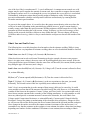
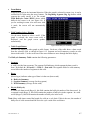
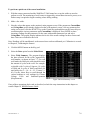
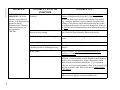
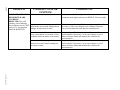
Example of a Weld Lobe
915
Force in Lbs.
An example of collected weld data is
shown in figure 3-1. In this graph, the
diamond shapes represent welds made.
The horizontal axis is the weld Current
(measured in KA) and the vertical axis
is Force (measured in lbs.). Although
this particular graph only shows force
and current, all weld parameters can be
toleranced using a Livingston monitor.
The locations of the diamonds show
exactly how much force was used at a
particular current for the displayed weld
set. For example, the circled diamond in
figure 3-1 indicates a weld made with
approximately 9.5 KA of weld current at
895 lbs. of force.
910
905
force
900
895
890
0
2
4
6
8
10
12
Current Rm s in KA
Figure 3-2 Example of a Weld Lobe for Force
To determine the lobe for this particular data set, each part associated with these welds would be
destructively tested. Suppose that testing revealed that the welds made within a range of about 908 to
914 lbs. of force, with a range of about 7 – 11 KA of current were all good. If a box is drawn to isolate
these ranges, as shown in figure 3-2, the area within that box is the weld lobe. The box itself represents
the tolerance limits, or the limits of the range in which good (high-quality) welds can be made. A
master is what provides the monitor with a weld signature that is within the weld lobe. Tolerances are
what define the boundaries of that box. Once a master is created and toleranced, Livingston monitors
will reject any welds that have fallen outside of the box (out of tolerance), while any welds inside the
box (within tolerance) will be accepted.
3-2
0430-INS-400 Rev. D
Every factor involved in making a weld has its own weld lobe and set of unique tolerances. There are
multiple parameters that can be measured and toleranced using a Livingston monitor. The WMS
program makes it easy to define, track and record tolerances for each parameter critical to the weld
process. For maximum flexibility, acceptable tolerances can be specified by absolute or relative values
when comparing weld data in real-time against a master.
Measured Parameters
Livingston monitors capture measurements from up to four sensors attached to a welder. From these
four measurements, the monitors then calculate and record the following parameters:
•
Current Rms
•
Part Expansion
•
Current Peak
•
Electrode Setdown
•
Voltage Rms
•
Conduction Angle
•
Voltage Peak
•
Energy
•
Force
•
Resistance (Dynamic)
•
Initial Part Thickness
•
Number of Halfcycles
•
Final Part Thickness
For a complete definition of each of these measured parameters, please refer to section 6, the WMS
Reference Guide.
Segments
Since there are many different weld processes, users may be more interested in observing and
analyzing certain time periods during a weld. To accommodate these differences and needs, Livingston
devised the concept of segments. A segment is simply a collection of halfcycles before, during and
after the firing of weld current. By default, there are three segments created when a master is made: the
Pre-Weld (Squeeze), Weld, and Post-Weld (Hold) segments. Different tolerances can be set for each
segment, segment lengths can be increased or decreased and new segments can easily be created.
Using segments, each weld can be divided into as many parts as necessary to focus on the data that is
critical to the weld process. Consider the following example:
Coated steel is being welded with the following weld schedule: 8 cycles of Squeeze, 10 cycles of Weld
and 12 cycles of Hold. The objective is to monitor the current density during the Weld time, to ensure
sufficient concentration for high-quality welds. According to the factory weld lobe, the current at the
electrodes during the weld must be 12 KA, with an allowable difference of only +/-0.5 Amp. After
examining preliminary weld data, it is discovered that the current during the first few halfcycles of the
Weld period is much less than 12 KA. The reason for the decrease is that the coating must first be
burned off before the weld current actually reaches the steel at the faying surfaces and makes the weld.
How can tolerances be properly set to accommodate the weld lobe specification of 12 KA +/- 0.5 Amp
without automatically rejecting welds during the time it takes for the coating to burn off?
0430-INS-400 Rev. D
3-3
To resolve this issue, the exact time (in halfcycles) needed for the weld current to burn through the
coating could be determined by examining collected weld data. Using this information, a segment
could then be added that would effectively divide the Weld segment into two. The first Weld segment
would start when the weld current fires, and would end when the coating had been burned off. The
weld current tolerances in this particular segment could be widened to accommodate the change in
current density when burning through the coating. The second Weld segment would begin at that point
when the weld current had reached the metal to be welded, and would end when the weld current
ceases. In this segment, the weld current tolerances could be tightened to ensure the necessary amount
of current (in the example, 12 KA, +/- 0.5 amps) to make a good weld.
Segments provide a useful means for organizing the weld data and comparing changes over time. The
ability to specify different tolerances within several different segments allows the user to precisely
isolate weld factors that may be critically important to weld integrity and include these factors when
accepting or rejecting welds.
Data Collection
Data can be collected for each halfcycle, segment and/or weld. Please refer to the General Setup
Menu in section 6, WMS Reference Guide.
Weld data is continuously recorded whenever the weld monitor is operating, however only a prespecified amount of data is stored. The monitor is 'triggered' at the instant that weld current is fired;
this moment is referred to as the trigger. The quantity of data stored is based on the trigger. The user
can choose a number of halfcycles prior to the trigger (the Pre-weld segment) and a number of
halfcycles after the current has ceased (the Post-weld segment), depending on the importance of this
data to weld analysis.
For example, a weld schedule may have 8 cycles (16 halfcycles) of Squeeze, 12 cycles (24 halfcycles)
of Weld and 8 cycles (16 halfcycles) of Hold. In this particular process, the force during the last six
halfcycles of the Squeeze period and the first eight halfcycles of the Hold are especially important.
Accordingly, the segment length can be set to include only those specific halfcycles. All additional
data before and after the indicated number of halfcycles would consequently be discarded by the
monitor.
3-4
0430-INS-400 Rev. D
Getting Familiar With The
WeldWise™ 2400
This chapter will review the external features of the WeldWise™ 2400 (hereafter referred to as 2400),
as well as the various menus and options of the Weld Monitoring Software (WMS) program, including
the proper shutdown procedure for all Livingston equipment.
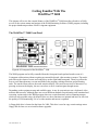
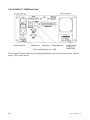
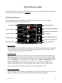
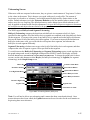
The WeldWise™ 2400 Front Panel
Figure 4-1 Front panel of the WeldWise™ 2400
The WMS program can be fully controlled from the front panel touch-pad and touch-screen of a
Livingston weld monitor without requiring an external keyboard, video monitor or mouse. The touchpad refers to the cluster of arrow and control keys on the right hand front panel. These keys allow the
user to scroll through menus, screens and fields in the program, making selections and performing
tasks. The touch-screen refers to the touch sensitive display. The touch-screen itself is interactive: by
pressing an item on the display, the user can select or move it and navigate through menus.
Depending on the equipment setup and available space, it may be convenient to use a keyboard, video
monitor and/or mouse. Although there are several different methods for performing each command and
executing various tasks in the WMS program, there are certain functions, such as renaming masters,
which are only possible using a keyboard. However, these functions are optional and have no effect on
the quality of weld monitoring. Use of a video monitor and mouse is optional.
A floppy disk drive is located on the front of a 2400. This drive is used to copy certain settings onto a
floppy disk for later use or to install software upgrades.
0431-INS-400 Rev. D
4-1
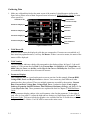
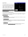
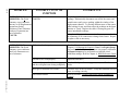
WMS Navigation and Editing
There are two modes in the WMS program: navigating mode and editing mode. Navigating mode
simply refers to moving from one portion of the screen to another or from screen to screen. Editing
mode refers to selecting an item for change and/or actually changing the value of it.
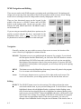
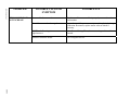
There are four directional arrows on the keypad. In the
middle of the arrow is a SELECT button, and an ENTER
button on the bottom right. On the top are three other
buttons: ESCAPE, MENU and HELP. The PRINT button is
on the bottom left.
If you are using an external keyboard, these options may be
quickly accessed with the 'hot keys', represented by the
underlined letters (ALT + letter). You can also use the
keyboard arrows instead of the arrows on the touch-pad.
Figure 4-2 Keypad buttons
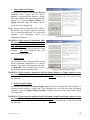
Navigation
Generally, anytime you move within a screen or from screen to screen, the location of the
cursor is shown by a highlighted or enhanced border.
ESCAPE This button reverses your path through the program. For example, if you selected
the Data option from the Main Menu, you can use the ESCAPE button to return to
the Main Menu. ESCAPE always takes you back one level at a time towards the
Main Menu of the program or cancels your previous action. If you press ESCAPE
enough times from anywhere in the program, you will always end up at the opening
program screen.
MENU
This button accesses the Main Menu from many, but not all, points in the program.
Use it to return to the Main Menu options.
Arrow
Use the arrow buttons to move up, down, left or right on the touch-screen. The
arrows will also allow you to change options once an item has been selected.
Editing
SELECT The SELECT button is used to select an item. This either performs the action
associated with that item, or puts you into Editing mode. A selected item is usually
highlighted, shown with a highlighted border or indicated with a flashing cursor.
Once an item has been chosen (shown by a highlighted or enhanced border) in the
touch-screen, press the SELECT button to highlight (shown by a different fill color)
that item for use or change. For example, if the item is a menu option, the program
opens to the next appropriate display. If the item is parameter, you can cycle
through a list of additional choices using the Arrow Buttons. If the choices show a
4-2
0431-INS-400 Rev. D
number, you can increase or decrease it by using the arrow buttons, or if you have a
keyboard you can simply type in the desired number. The SELECT button takes you
to the next level or the next set of choices. You can also double click the item with a
mouse or press Enter on an external keyboard.
ENTER
When you have changed a value or completed some type of operation in the
program, use the ENTER button to confirm the change and store the new value. For
example, if you change the value of a tolerance using the Arrow Buttons, use the
ENTER button to confirm the change and save the new tolerance setting. You can
do this using the ENTER button on the touch-pad or by pressing the Enter button on
a keyboard. Pressing the ENTER button will return you to navigation mode.
Note: Once you have selected and highlighted a value to be changed, you must use
the ENTER button to exit the highlighted item, even if the value has not changed.
Other Buttons
HELP
This button accesses the built-in help features of the WMS program. Although new
help features are continually being incorporated into the program, you may find that
in some windows the HELP button does not activate. If you are having difficulties
with a particular feature, please consult this manual or your Livingston representative
for further information.
PRINT
This button will print the contents of the WMS touch-screen window using the builtin thermal printer. Printing can take place from most of the screens that appear in the
display window. NOTE: The printer will only print what is visible in the display
window to the left of the virtual keypad. Printing can be configuration for use with
an external printer, or network printer.
0431-INS-400 Rev. D
4-3
The WeldWise™ 2400 Back Panel
Figure 4-3 Back panel of a 2400
The back panel features connectors for attaching peripherals, such as an external keyboard, monitor,
printer, UPS, or other device.
4-4
0431-INS-400 Rev. D
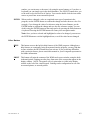
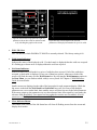
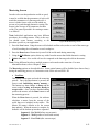
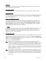
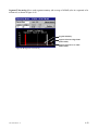
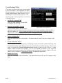
Proper Shutdown Procedure
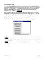
The WMS program uses databases to keep track of configuration settings and weld data. Properly
shutting down or exiting the software is important since improper shutdown may result in a corrupt
database. Many times a corrupt database can be repaired but other times data may not be recovered.
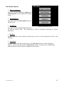
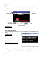
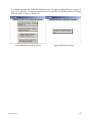
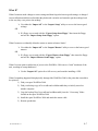
Proper Manual Monitor Shutdown Procedure:
1. Use either the ESCAPE key or MENU key to
return to the Main Menu;
2. Select Shutdown;
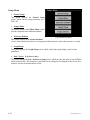
3. You will be taken to a shutdown menu with four
different options:
4. Select option 2, "Yes, I'm sure. Shutdown
Windows too." Once this option is selected, the
program will initiate its shutdown cycle.
A message box will appear with the header
"Shutdown in Progress". It is crucial to let the
monitor finish this cycle uninterrupted.
Figure 4-4 Shutdown screen
When it has finished, another message box will appear saying: "It is now safe to turn off your
computer." When this message appears— and only when this message appears— the Livingston
monitor can be turned off using the power switch on the back panel of the unit.
Uninterruptible Power Supply (UPS)
Many manufacturing facilities have frequent power problems. For permanent installations, the
installation of a UPS (uninterruptible power supply) is recommended to avoid a “hard” shutdown of
the computer due to sudden loss of power. This kind of shutdown may result in corrupt databases and
in some cases damage to Windows system files leaving the computer inoperable.
If your weld monitor was purchased with the UPS option, the necessary software was installed and
configured at the factory. The pre-loaded software will either activate the startup or shutdown
procedure in the WMS program. For information about how to install a UPS for use with a Livingston
monitor, please refer to Attaching Peripherals in Chapter 11, Appendices.
The following actions should never be taken:
•
NEVER shut off your Livingston monitor using the power switch on the back panel without
having gone through the proper shutdown procedure.
•
NEVER disturb the Livingston monitor or UPS (if equipped) while it is cycling through the
shutdown sequence.
Failure to comply with these guidelines may irreparably damage the Livingston database. Livingston
will not be responsible for damage to any monitor incurred through failure to comply with these
guidelines. For additional information about using or obtaining a UPS, please refer to the APC UPS
manual.
0431-INS-400 Rev. D
4-5
4-6
WMS Quick Start Guide
This chapter is a quick how-to guide to begin using a Livingston weld monitor. The provided example
describes the necessary steps to collect and view data, create a master and set tolerances.
Note: Since this is only an example, it assumes the following:
-
All hardware has been properly installed, all sensors have been properly calibrated, and the
2400 is turned on and ready to monitor;
-
You are familiar with how to navigate and edit functions within the WMS program (see
Chapter 4, Getting Familiar With The WeldWise™ 2400).
Due to the variety of welding processes and schedules throughout the welding industry, the following
example steps may not be applicable to every welding process. For a complete description of all
functions in the WMS program, refer to Chapter 6, WMS Reference Guide.
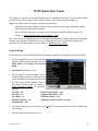
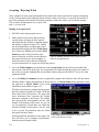
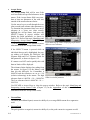
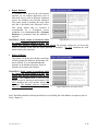
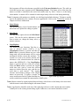
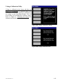
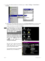
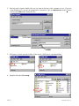
General Setup
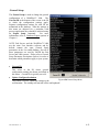
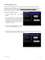
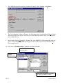
The first step is to confirm that the general configuration settings are appropriate for this procedure.
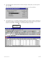
1. With the equipment set up for monitoring
and the WMS program running, go to the
Main Menu. Select Setup, then General
Setup.
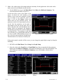
2. Current ID should be set to 60.
3. For the purposes of this example, set the
General Setup parameters to the following
values (parameters not mentioned here can
be left at their default settings). Refer to
the General Setup Menu in Section 6,
WMS Reference Guide, for parameter
specifics.
Pre Size = 10
Post Size = 10
Post Delay = 0
Masters Enabled = Yes
Segment Size = 100
Halfcycle Data Mode = All
Segment Data Mode = All
Weld Data Mode = All
Segment Tolerance Mode = Average
4. Once these changes have been made, use the Update Configuration button to update settings to the
weld monitor.
5. ESCAPE to the main program screen.
0432-INS-400 Rev. E
5-1
Gathering Data
1. Make one weld and then look at the main screen of the monitor. It should appear similar to the
figure below (Please refer to Main Program Screen in Section 6, WMS Reference Guide, for main
screen specifics):
Weld Number
(last weld recorded)
Weld Master ID
Parameter Display #1
Weld Status
Indicators
Parameter Display #2
ID Select
Parameter Display #3
Job Status
Indicators
Parameter Display #4
Clear Indicators
Button
Figure 5-2 Main screen
•
Weld Master ID
Indicates which master the displayed weld data was compared to. If masters are not enabled, or if
there aren't any updated masters, it will say No Master. If there is an active master, the name of the
master will be displayed.
•
Weld Number
The weld number indicates which weld corresponds to the displayed data. In figure 5-2, the weld
number is 3. This means that for Weld 3, the Current Rms was 8.494 KA, the Voltage Rms was
0.886 Volts, the Force was 664 lbs. and the Hcycle On Cnt was 20 Halfcycles. Each time a weld
is recorded by the monitor, the weld count will increase.
•
Parameter Displays
Four parameters may be viewed on the main screen at one time. In this example, Current RMS,
Voltage RMS, Force and Hcycle On Cnt are shown. Your screen may look different if other
parameters have been selected. There are multiple parameters recorded by the monitor: Current
Rms, Current Peak, Voltage Rms, Voltage Peak, Force, Conduction Angle (Cond. Angle),
Setdown, Expansion, Initial Thickness, Final Thickness, Resistance, Energy, and Halfcycle On
Count (Hcycle On Cnt). These parameters are explained in detail in Chapter 6, WMS Reference
Guide.
In each parameter display window is the weld summary value for that parameter. To the right of
each value is a bar graph. To adjust the high and low settings see Graph Setup in Section 6, WMS
Reference Guide. You can select the bar graph to view a trend of the last 30 welds taken, as shown
in figures 5-3 and 5-4 below. Use ESCAPE to return to the main screen.
5-2
0432-INS-400 Rev. E
Figure 5-3 Select the bar graph to the right of a
parameter (shown here with an outline around
it) by touching the graph on the screen.
•
Figure 5-4 The Trend Graph for the selected
parameter will display information for up to 30 welds.
POD / ID Select
Pod / ID indicates which WeldWise™ 2400 ID is currently selected. The factory setting is 60.
•
Weld Status Indicators
Indicates the status of the displayed weld. If a check mark is displayed then the weld was accepted.
If a flashing up or down arrow is displayed then the weld was rejected.
•
Job Status Indicators
Indicate whether any weld made in a series of welds has been rejected. If all of the welds have
accepted, a check mark is displayed. If any one of them has rejected, either one or both of the
arrows will flash, the same as in the Weld Status box. By selecting the Weld Summary option in
the Data Menu, you can find out which weld(s) were rejected. See Chapter 6, WMS Reference
Guide for more details.
Smaller arrows are displayed to the right of the bar graphs for each parameter display. While the
big arrows in the both the Weld Status and Job Status boxes tell you if any of the multiple
parameters are over or under limit, these smaller arrows will show up next to the failed parameter.
If the arrow points up, the parameter was over the tolerance limit; down signifies it was under the
tolerance limit. Remember, if no master has been updated or masters are not enabled, all weld
parameters will fail by default and the arrows will flash.
•
Clear Indicator Button
This button at the bottom of the Job Status box will clear all flashing arrows from the screen and
display check marks.
0432-INS-400 Rev. E
5-3
2. Make a few welds using weld settings and parts customary for the application. After each weld is
made, notice the weld number increase by one.
•
Use the MENU key to go to the Main Menu. Select Data, then Halfcycle Summary. The
screen should look similar to figure 5-5.
At the top of the screen is the name of the
master to which the weld number at the
bottom of the screen was compared. If there
was no master in use when the weld was
made, it will say No Master. Below the
master name are two parameter boxes. The
parameter on the left is represented by the axis
on the left; the parameter on the right is
represented by the axis on the right. You can
select either box and scroll through the list to
change which two parameters are displayed.
The parameter in the left box will be displayed
as a non-bold line. The parameter in the right
box will show up as a bold bright solid line. If
you have trouble differentiating between the
two, select the same parameter in both boxes.
The horizontal axis is measured in halfcycles.
Figure 5-5 Halfcycle Summary (graph)
If the graph extends vertically off the screen, you can change the graph display range by doing the
following:
1. ESCAPE to the Main Menu. Select Setup, then Graph Setup.
2. Select the value in the Graph Low or Graph High boxes that correspond with the parameter
displayed in the Halfcycle Summary screen and scroll through or type in the desired high / low
value. When you return to the Halfcycle Summary screen, the changes will take effect
immediately.
Figure 5-6 By changing the Low/High values for a
displayed parameter in the Graph Setup…
5-4
Figure 5-7 …you can alter the graph display on the
monitor.
0432-INS-400 Rev. E
At the bottom of the Halfcycle Summary screen are two buttons: Zoom and Table. In between
them is a box labeled "Weld:" that is followed by the number of the weld being displayed.
•
Selecting the Table button will display a
table of the collected weld data for the weld
by the halfcycle as shown in figure 5-8.
Definitions of these parameters can be
found in Chapter 6, WMS Reference Guide.
•
The information shown in this table is for
one weld, the weld number displayed on the
bottom of the screen. To see data for past
welds, select the Weld number by touching
it on the screen and using the arrow keys to
scroll through or enter the desired weld
number.
•
To return to graph format, select Graph.
Figure 5-8 Halfcycle Summary (table)
Highlight any cell in the Accept Status column and press the SELECT key. A window will appear
giving a summary of failed parameters as shown in figure 5-9. By highlighting a specific parameter
value and pressing the SELECT key, a window will display the high and low tolerance limits for
that parameter based on the master tolerances. Refer to Chapter 6, WMS Reference Guide for
additional details.
Figure 5-9 Pop-up window of failed parameters in the Figure 5-10 Tolerance Limits are displayed by using
Halfcycle Summary
the SELECT key on a parameter value once a master
has been made and toleranced
•
ESCAPE to the Data Menu and then select Weld Summary.
0432-INS-400 Rev. E
5-5
•
•
The screen will look similar to figure 5-11 below. Unlike the Halfcycle Summary screen, the
Weld Summary screen displays recorded weld summary information for each weld made. The
most recent weld recorded will always be at the top of the list; you can scroll down to see
information for each weld. Definitions of additional parameter headings in this screen can be
found in Chapter 6, WMS Reference Guide.
For the Weld Summary screen use the SELECT key the same way as in the Halfcycle
Summary screen to get a breakdown of failed parameters.
Figure 5-11 Weld Summary
5-6
0432-INS-400 Rev. E
Creating a Master
Now that you have observed recorded weld data, we will make a master which will provide known
good values to compare subsequent welds against.
Note: An appropriate weld schedule should be established before creating a master. General Setup
Parameters and tolerance defaults should be set appropriately before creating a new master.
To start data capture for a new master:
1. Use ESCAPE to exit the Weld Summary
screen, then press the MENU key to display the
Main Menu options;
2. Select Mastering;
3. Select New from the options. The message
displayed reads "Initializing master memory,"
then "Creating new master: Ready to accept
welds..." The New button changes to Done.
4. Make one weld, using weld settings and
standard parts customary for the application..
Figure 5-12 Mastering screen, ready to accept welds.
5. Press the Done button to end the data capture.
The screen will say "Updating master weld
set." The date/time stamp of the new master is displayed at the top left of the screen.
6. Your screen should now look similar to figure
5-13. Press the Update button to save the
newly created master into the monitor's
memory.
Note: Anytime you create a new master,
change the name of a master or change
tolerances for a master you MUST use the
Update button for the new master /
tolerance changes to take effect.
The 'MO1' after the date/time stamp of a master
refers to the Master Select (binary select)
number. For more information about Bin
Figure 5-13 Mastering screen with new master
Selects, please refer to Chapter 6, WMS
date/time stamp displayed at the top left. Press
Reference Guide.
Update to update master for use by the monitor.
0432-INS-400 Rev. E
5-7
Accepting / Rejecting Welds
Once a master has been created and updated, the monitor has a basis on which to compare subsequent
welds. If all parameters fall within the master tolerance limits, the weld is accepted by the monitor. If
any of the parameters fall outside of the master tolerance limits, the weld is rejected by the monitor.
This section will demonstrate an accepted weld
and a rejected weld.
Making an accepted weld
1. ESCAPE to the main program screen.
2. Make another weld. Notice that the newly
created master is displayed in the top left,
indicating that the weld was compared against
this master, as shown in figure 5-14. Ideally
this weld should have accepted and a check
mark should be displayed in the Weld Status
box. If there are flashing arrows in the Weld
Status box, then weld rejected for some
reason. Either the weld was rejected because
Figure 5-14 Main program screen with new master
date/time stamp displayed
the master tolerances are set too tightly, or
either the master weld or the last weld made
was not characteristic of a typical weld for this process.
3. Go to the Weld Summary screen and look at the Accept Status for the weld you just made (the
most recent weld will be at the top). An Accept Status of 0 indicates that the weld was accepted. If
the weld was rejected, highlight the Accept Status number and press the SELECT key to see what
parameters failed.
4. Go to the Halfcycle Summary Screen to graphically compare the halfcycle data with the master
tolerance limits. Change the parameter in the top left box to Current Rms and the parameter in the
top right box to Hcycle Limits. Your screen
should now look similar to figure 5-15.
The thin vertical arrows pointing down separate
the three default segments (Pre-weld, Weld and
Post-weld) of the weld process. The upper and
lower horizontal lines represent the default
tolerances assigned to the master. The middle
line represents the weld signature for the weld
number at the bottom of the screen. As you can
see, the parameter Current Rms was within the
tolerance defaults of this master. For the weld
to be accepted, all parameters must be within
the master tolerance limits.
Selecting different parameters in the upper left Figure 5-15 Halfcycle Summary, Current Rms
shown with Halfcycle Limits
box will allow you to compare all parameters
with the master tolerance limits.
5-8
0432-INS-400 Rev. E
5. If for some reason your weld rejected, try making more welds to see if any accept. If the welds
continue to reject, review the failed parameters and skip ahead to the tolerancing section of the
WMS quick start guide. Adjust master tolerances until welds are accepted and continue with the
following steps to make a rejected weld.
Making a rejected weld
Now we will deliberately reject a weld and see
what the resulting halfcycle data looks like. We'll
use an increased halfcycle count as an example.
1. ESCAPE to the main program screen.
2. Increase the weld cycle count by 2 on your
weld controller.
3. Make a weld using the new weld schedule and
observe the monitor screen. You should see a
blinking arrow in the Weld Status box, as
shown in figure 5-16. If one of your displayed Figure 5-16 Main program screen showing
parameters is Hcycle On Cnt, you'll also see a REJECTED weld
small blinking arrow next to the bar graph.
4. Go to the Halfcycle Summary screen. It should look something like figure 5-17.
Notice that although the line representing
Current Rms has remained within the tolerance
boundaries, it has extended past the Weld
segment boundary. Because of the 4 added
halfcycles in the weld schedule, this weld did
not match the master (the master was made
without the extra 2 cycles) and as a result was
not passed (REJECTED).
5. Remove the two additional cycles from your
weld schedule before proceeding.
Figure 5-17 Halfcycle Summary of REJECTED weld
0432-INS-400 Rev. E
5-9
Tolerancing
In the WMS program, welds are accepted or rejected based on specific tolerances assigned for
individual parameters within an active master. Tolerances can be defined as relative or absolute values.
Refer to the Tolerancing in section 6, WMS Reference Guide, for a definition of relative and absolute
tolerances.
As weld data is recorded and compared to the master tolerance limits, the monitor flags values that are
out of tolerance. In this section, we'll change the tolerances for the master that was just made and then
accept / reject welds based on those master tolerance limits.
1. From the Main Menu, select Tolerancing.
If nothing comes up, press the Select
Master button and highlight the master we
just made. Press SELECT. Your screen
should look similar to figure 5-18.
2. Touch anywhere in the Weld segment
(middle of the screen) so that the pointer
(thinnest vertical arrow) is in Segment 1
(Weld segment). Under HALFCYCLE
TOLERANCES, the screen should say
Segment: 1.
Figure 5-18 Tolerancing screen
3. Select the parameter Current Rms.
4. Select the Low number and change it to –1.
Select the High number and change it to 1.
5. Press the Update button. After a few
moments, the screen should now look
similar to figure 5-19. Notice that the
tolerance bands have adjusted accordingly.
Figure 5-19 Master with Low/High tolerances
changed
6. ESCAPE to the main screen and make a
weld. If the weld passes, go to the Halfcycle Summary screen. Your Halfcycle Summary screen
should look similar to figure 5-20. Notice that the Current Rms line is within the set tolerances.
Now we'll lower the heat for the next weld so you can see what happens.
5-10
0432-INS-400 Rev. E
7. Decrease the heat on your weld schedule by 20.
(If your schedule is set for 45% heat, lower it to
25% heat). ESCAPE to the main screen and
make a weld.
8. The Weld Status box should display flashing
arrows, indicating a REJECTED weld, as shown
in figure 5-21. Go to the Halfcycle Summary
screen. It should look similar to figure 5-22.
Notice that the Current Rms line is below the
lower
tolerance
boundary,
causing
a
REJECTED weld.
Figure 5-20 Halfcycle Summary for ACCEPTED
weld
Summary
Remember, this guide is intended as an example
only— the creation of masters and tolerances for
individual weld processes will vary. Please refer to
Chapter 6, WMS Reference Guide for a complete
description of all functions in the WMS program, or
use Chapter 10, Troubleshooting Guide for more
information about mastering.
Figure 5-21 Main program screen displaying a
REJECTED weld (Current Rms, etc. too low)
Figure 5-22 Halfcycle Summary for REJECTED
weld
0432-INS-400 Rev E.
5-11
5-12
WMS Reference Guide
This chapter reviews every screen in the WMS program. There is an organizational chart (WMS Road
Map) for the all screens in Chapter 11, Appendices.
Main Program Screen
The main program screen of the WeldWise™ 2400 is shown in figure 6-1 below. It displays
information from the most recently recorded weld.
Weld Master ID
Weld Number Display
Weld Status High Limit indicator
Parameter Display #1
Weld Status Low Limit indicator
Parameter Display #2
POD / ID select
Parameter Display #3
Job Status High Limit indicator
Job Status Low Limit indicator
Parameter Display #4
Clear Job Status button
Figure 6-1 Main program screen
•
Pod / ID Select
This field displays/selects the ID that is currently in use. Weld data on the main screen corresponds
to the displayed ID. Unless noted otherwise, when navigating to other screens all data, settings,
commands and updates are specific to this Pod/ID.
•
Weld Master ID
If the Pod/ID has been set up to compare welds to a master (contains master tolerance limits), the
Master ID is displayed. If masters are not enabled, or there is no master for this weld, the display
will read No Master. If the weld data for this weld was used to generate a master, then the display
will read Master Weld. In the figure above, the Master ID is 3/13/01 3:50:40 PM M01, where
3/13/01 3:50:40 PM is the data/time when the master was created followed by M01 which
indicates which Binary Select is associated with the master (Binary Select 01 for this master).
There are a total of 15 binary selects available for use with a WeldWise™ 2400.
•
Weld Number Display
This field displays the weld number corresponding to the weld data on the Main Screen. This is the
number of monitored welds since the weld data was last deleted from the database.
0433-INS-400 Rev. E
6-1
•
Weld Status High/Low Limit Indicators
One or both of the indicators will be displayed if the most recent weld was rejected. The top arrow
will flash if a parameter exceeded high limits; the bottom arrow will flash if a parameter exceeded
low limits. Both indicators will flash when both high and low limits were exceeded. Both
indicators will also flash if there is no master made or if masters are not enabled in the General
Setup.
•
Job Status High/Low Limit Indicators
One or both of the indicators will be displayed if for any of the welds were rejected since the Job
Status was last cleared. Both indicators will also flash if no master has been created and updated, or
if masters are not enabled in the General Setup Menu.
•
Weld/Job Status Good Indicator
is
If all of the weld parameters are within the master tolerance limits, a “Check Mark”
displayed in place of the high/low limit indicators.
•
Clear Job Status Button
When the Clear button is pressed, both Job Status and Weld Status are cleared, and a “Check
Mark” is displayed.
•
Parameter Displays
All of the different weld summary parameters are available from the main screen. Each parameter
display can show data for one of these parameters. A parameter display section of the main screen
is shown in figure 6-2 below:
Bar Graph and Trend
Graph Display Button
Parameter Value
Parameter High Limit indicator (not shown)
Parameter Low Limit indicator
Parameter Name
Graph Low/High Limits
Figure 6-2 Parameter display
•
Parameter Name
Each parameter display can show data for one of these parameters:
Current RMS
Conduction Angle
Final Thickness
Current Peak
Setdown
Resistance
Voltage RMS
Part Expansion
Power Factor
Voltage Peak
Initial Thickness
Halfcycle On Count
Force
Energy
Note: Power Factor is not yet implemented and will display zero.
To select a different parameter in a parameter display, touch
the parameter name on the touch-screen, or navigate to the
parameter name with the arrow keys so that the parameter
name is outlined and use the SELECT button to highlight it, Figure 6-3 Touch on the parameter
display and use the SELECT button to
as shown in figure 6-3. Once the parameter box is
highlight it
highlighted, the up/down arrows will scroll through the
parameter list.
6-2
0433-INS-400 Rev. E
•
Parameter Value
The most recent weld summary data for the selected parameter is displayed. The units displayed
may be changed in the Tolerance Defaults screen. In figure 6-3, the weld summary data for
Current Rms is displayed in KA.
•
Graph Low/High Limit
Each parameter has its own graph limit settings. These can be specified in the Graph Setup option
of the Setup Menu. In figure 6-3, the Graph Low limit is –2 and the Graph High limit is 12.
•
Parameter High/Low Limit Indicators
These are displayed if the current weld’s parameters are not within the master tolerance limits. The
top arrow will flash if a value exceeded its high limit; the bottom arrow will flash if a value is
below its low limit. If the value for that parameter is within tolerances, no indicator is displayed.
Note: If a parameter was out of tolerance but is not shown in one of the parameter displays, the
Weld Status high/low indicators will flash. In this situation, you can scroll through the parameters
or use the Weld Summary to determine why a weld has failed.
•
Bar Graph and Trend Graph Display button
This field shows the parameter value as a bar graph between the high and low graph limits.
Note: If the data value falls outside the graph limits, the bar will not be visible. Graph limits may
be changed using the Graph Setup option of the Setup menu.
The bar graph also serves as a button to display a
trend graph for the selected parameter. Touch (on
touch screen), or navigate to the bar graph and use
SELECT. A trend graph of the last 30 welds is
displayed. The weld number is displayed on the xaxis (horizontal) and the data parameter value is
displayed on the y-axis (vertical). To return to the
Main Screen, use the ESCAPE button.
Figure 6-4 Touch (touch screen) on the
parameter bar graph to display a Trend Graph
for that parameter
Figure 6-5 Example of a Trend Graph for
Current Rms.
0433-INS-400 Rev. E
6-3
Main Menu Options
Selecting the MENU button on the touch-pad
displays the Main Menu, as shown in figure 6-6.
You can return to the Main Menu from sub-menus
by using the MENU or ESCAPE buttons.
Note: If you are using an external keyboard, you
may quickly access menu options by holding
down the ALT key and pressing the underlined
letter. For example, to go to the Data Menu from
the Main Menu, hold down ALT, and press D.
•
Data
Figure 6-6 Main Menu
This option displays the Data Menu which
allows you to review weld data, access the system log, and perform database backup / restore
options.
•
Mastering
This option displays the Mastering screen, which allows you to create and edit weld masters.
•
Tolerancing
This option displays the Tolerancing Master screen, which allows you to adjust the high and low
tolerance limits of each parameter in a selected master.
•
Setup
This option displays the Setup Menu, which provides setup options to help you configure the
system and to calibrate sensors.
•
Shutdown
This option displays a list of shutdown choices.
6-4
0433-INS-400 Rev. E
Data Menu Options
•
Halfcycle Summary
This option displays Halfcycle, Segment and
Weld Summary data in a graphical or tabular
format.
•
Weld Summary
This option displays Weld Summary data in a
tabular format.
•
System Log
Figure 6-7 Data Menu screen
This option displays System Log information
for different system events. This information is used by Livingston technicians for system
diagnostics.
•
Database
Displays sub-menus and commands which backup, restore or delete information from the weld
databases.
•
Scope Data
Displays raw data from the external sensors. The Scope Data feature is used for diagnostic
purposes, and must be enabled in the Setup Menu to operate. It should not be enabled during
normal production. Please contact Livingston for more details.
0433-INS-400 Rev. E
6-5
Halfcycle Summary Screen
The WMS software displays weld data on a halfcycle, segment and weld basis. If the system is set up
to record halfcycle information, data records are stored in a database for each halfcycle of the weld.
Each stored weld data record contains data values for all parameters, as well as other system
information.
Weld Master ID
Left y-axis parameter
pickbox
Right y-axis parameter
pickbox
Table / Graph button
Zoom button
Weld number select / display
Figure 6-8 Halfcycle Summary (graph)
Weld Halfcycle Count
The Halfcycle Summary graph can display two Total Segments
Beginning Segment
(Zoom only)
parameters at a time, as shown in figures 6-8 and
6-9. Halfcycle data points are shown, with the
Weld Halfcycle Count
points connected to form a trace. The summary
(Zoom only)
graph displays data traces for any two parameters.
Graph description
The halfcycle count of the weld (including the
Figure 6-9 Halfcycle Summary
pre-weld and post-weld segments) is shown on the
(graph)
x-axis (horizontal).
•
Left/Right axis Parameter Select
The left parameter select box corresponds to
the left y-axis (vertical), and the brighter trace
on the touch-screen. The right parameter
select box corresponds to the y-axis on the
right, and the dimmer trace on the touchscreen.
The parameter pick box on the right can also
be set to Hcycle Limits (figure 6-10) or
Segment limits. If a master has qualified the
weld, Hcycle Limits or Segment Limits will
show the upper and lower tolerance limits on
each halfcycle for the parameter in the left Figure 6-10 Current Rms shown with Halfcycle
pickbox.
tolerances
6-6
0433-INS-400 Rev. E
•
Zoom Button
Expands the graph in the horizontal direction. When the graph is selected in zoom view, it can be
scrolled left or right using the arrow buttons. The Beginning Segment (Beg Sg) defines which
segment the cursor (arrow) is in. The second
Weld Halfcycle Count (WHC) shows which
halfcycle the cursor is on (see figure 6-9). If
you are working in zoom view and a new weld
is made, the screen will not automatically
update.
• Weld Number Select / Display
Use the arrow buttons to select a weld. If the
graph is selected, the most recent weld is
displayed, and the graph screen updates
automatically.
• Table/Graph Button
Figure 6-12 Halfcycle Summary (table)
Switches the display to either graph or table format. Each row of the table shows a data record
from the selected weld, as shown in figure 6-12. Segment and weld summary records are also
shown in this table. Use the scroll bars or the arrow buttons to move through the table display.
The Halfcycle Summary Table contains the following parameters:
•
Segment
A weld is divided into segments. The segment field indicates which segment the data record is
from. By default, 0 = Pre-weld; 1 = Weld; 2 = Post-weld. The segment field of a weld summary
record shows the number of segments in the weld.
•
Rtype
(Record type) indicates what type of data is in the row (data record).
0 = Halfcycle Summary
1 = Segment Summary (average for the segment)
2 = Weld Summary (average for the weld)
•
Hcycle (Halfcycle)
In a halfcycle data record (Rtype 0), this field contains the halfcycle number of the data record. In
a segment record (Rtype 1), this field contains the number of halfcycles in the segment. In a weld
record (Rtype 2), this field contains the number of halfcycles in the weld.
Note: Many weld timers control the length of a weld on a cycle basis. If this is the case, the number of
halfcycles of weld current should be twice the cycle count of the weld timer.
0433-INS-400 Rev. E
6-7
•
Accept Status
The Accept Status field will be zero if the
weld was within all specified tolerances in the
master. If the Accept Status field is not zero,
then at least one parameter of the weld was
outside of the master tolerance limits.
Use the arrow keys to scroll through the rows
(data records) and columns (data parameters).
To determine the parameters that were out of
tolerance in a given row (data record),
highlight the Accept Status, and press the
SELECT button. A pop-up window will
display the failed parameters, as shown in
figure 6-13. Refer to the topic Identifying and
Interpreting Accept Status Codes (Chapter
11) in the Appendices of this manual for more
information about the Accept Status codes.
Figure 6-13 Pop-up window displaying all parameters
that were out of tolerance
If the SELECT button is pressed while an
individual data record is highlighted, the popup window will display the Halfcycle, and
Segment High and Low Tolerance limits for
that parameter, as shown in figure 6-14.
If a master was NOT used to qualify this weld
then no limits will be displayed.
The tolerance limits displayed are taking from
the master. In figure 6-14 the Master weld
data (for this halfcycle) for CurrentRms is
0.006786 and the tolerances are set to +/-10
(relative tolerancing) in the master. The high Figure 6-14 Pop-up window displaying tolerance
tolerance limit is 0.006786 + 10 = 10.006786. limits for selected parameter
The Low tolerance limit is 0.006786 - 10 = 9.993214.
Use ESCAPE or Arrow Keys to close the pop-up window. Refer to the topic Identifying and
Interpreting Accept Status Codes (Chapter 11) in the Appendices of this manual for more
information about the Accept Status codes.
•
CurrentRms
The RMS (Root-Mean-Square) current in a halfcycle, or average RMS current for a segment or
weld.
•
CurrentPeak
The peak (positive or negative) current in a halfcycle, or the peak current in a segment or weld.
6-8
0433-INS-400 Rev. E
•
VoltageRms
The RMS voltage in a halfcycle, or average RMS voltage for a segment or weld.
•
VoltagePeak
The peak (positive or negative) voltage in a halfcycle, or the peak voltage in a segment or weld.
•
Force
The average force at the electrode tips during the halfcycle, segment or weld (average of Pre, Weld
and Post segment half cycles).
•
Set Down
Set Down is the decrease in thickness as a part is welded (relative to initial thickness).
Halfcycle: Set Down is the lowest thickness during the halfcycle minus the Initial Thickness value
at the beginning of the weld (halfcycle 0 from segment 1).
Segment: Set Down for a segment is lowest Set Down reported for a halfcycle within the segment.
Weld: Set Down is the difference between the initial thickness at the beginning of the weld
segment (halfcycle 0 from segment 1) and the Final Thickness at the end of the Post segment.
•
Expansion
Expansion is the increase in thickness as a part is welded (relative to initial thickness).
Halfcycle: Expansion is the highest thickness during the halfcycle minus from the Initial Thickness
value at the beginning of the weld (halfcycle 0 from segment 1).
Segment: Expansion for a segment is the highest Expansion value for a halfcycle within the
segment.
Weld: Expansion is the highest Expansion value from all of the segments (excludes PRE).
•
Initial Thickness
The thickness of the workpiece at the start of a halfcycle, segment or weld (Initial Thickness from
the first halfcycle in segment 1, the first weld segment).
•
Final Thickness
The thickness of the workpiece at the end of a halfcycle, segment or weld (final thickness from the
POST segment).
•
CondAngle (Conduction angle)
A measure in degrees of how long the weld timer SCR's were turned on, allowing current flow
during a halfcycle. The average conduction angle for a segment or weld.
•
Resistance (dynamic)
The calculated dynamic resistance of the workpiece during the halfcycle, equal to Voltage RMS
divided by Current RMS. The average resistance for a segment or weld.
0433-INS-400 Rev. E
6-9
•
Energy
The calculated energy during the halfcycle, equal to Current RMS multiplied by Voltage RMS. The
average energy for a segment or weld.
•
Power Factor
Power Factor is not yet implemented and will display zero.
•
Cyc Len
Cyc Len shows the number of samples per halfcycle in the A-D conversion. For Rtype 0, this
number is typically between 102 and 107 (half cycle @60Hz sampled at 12.5kHz). This field is
used by Livingston technicians as a diagnostic tool and should generally be ignored.
•
Date/Time
The date and time when the halfcycle, segment or weld data was recorded.
•
MasterID
Name of the master used to qualify the weld.
•
Bin Select (Binary Master Select)
For each POD / ID there are up to 15 masters which are selected using the binary select inputs. The
Bin Select reported in the weld data indicates the binary select setting or master number used for
this weld. Example: A Bin Select of 3 indicates that master associated with binary select 3 was
used. Typically the binary select number corresponds with the weld schedule number or the
sequential order of welds made by the welder during a part cycle.
Note: A binary select of 16 may appear if a master was created while an external binary select of 0
was selected. This is intended as a diagnostic aide for those trouble-shooting external binary
select timing problems.
6-10
0433-INS-400 Rev. E
Weld Summary Screen
The Weld Summary displays a table of stored
weld summary data records (Rtype 2), with the
most current record at the top.
Use the arrow keys to scroll through the rows (data
records) and columns (data parameters).
To determine the parameters that were out of
tolerance in a given row (weld data record), pick
that row and press the SELECT key. A pop-up
window will display the offending parameters, as
shown in figure 6-16. Use ESCAPE to close the Figure 6-15 Weld Summary
pop-up window.
To view the weld tolerance limits for a specific
parameter, navigate to the data for that parameter
and press the SELECT key. A pop-up window will
display the weld tolerance limits. Use ESCAPE to
close the pop-up window.
In addition to many of the Halfcycle Summary
parameters described in the previous section, the
Weld Summary parameters also include the
following:
•
Weld
The weld number, with the most recent at the
top.
•
Figure 6-16 Pop-up window displaying all
parameters that were out of tolerance
Hcycles On
Number of halfcycles in the weld that actually had current flow.
Note: The Rtype field is omitted because all weld summary records have the same record type (2).
Weld summary data records are also shown in the Halfcycle Summary table.
0433-INS-400 Rev. E
6-11
System Log Screen
•
System Log
This screen displays a table of recorded system
information. It is an event log with date/time
stamps intended for diagnostic purposes.
It is recommend that the system log be deleted
periodically as it does add to the size of the
livco.mdb database. It is also recommend that a
‘Compact Database’ be performed following the
deletion of system log entries.
Figure 6-17 System Log
6-12
0433-INS-400 Rev. E
Database Management
The WMS software running on the WeldWise™ 2400 uses Microsoft Access database files for storing
configuration, calibration, masters, master tolerance limits, and weld data. This section describes all of
the database operations available in the Database Management Utilities screen. Recommendations for
maintaining your WeldWise™ 2400 databases can be found in the Recommended Database
Management section in Chapter 11, APPENDICES.
Before performing any database functions, all remote user interfaces and applications accessing the
database should be closed. Database functions should be performed from the WeldWise™ 2400 weld
monitor only. Some options will allow you to cancel the action being performed. If the action is
cancelled, you will need to shutdown and restart the weld monitor.
Note: Weld data cannot be recorded and welds cannot be monitored during any database operations.
Typically weld accept/reject status will be unavailable depending on system configuration.
Figure 6-18 Database Management options
•
Import
This option displays the import menu, which allows data and setup information to be retrieved
from backup databases.
•
Export
This option displays the export menu, which allows data and setup information to be stored to
backup databases.
0433-INS-400 Rev. E
6-13
•
Compact Database
System data records are constantly added to
and deleted from the database during normal
operation. When certain data records are
deleted from the database (e.g., Delete
System Log or Delete Master is performed),
space for these records is not automatically
reclaimed. The Compact Database option
removes all unused records from the database
files. If you copy databases to an archive over
the network, the Compact Database
command will reduce the archive space
required. This compact option is basically the
same compact tool that is provided with
Microsoft Access.
Figure 6-19 Compact Database
WARNING: Welds cannot be monitored while
the Compact Database option is in use. Any
remote user interface windows must also be
closed. A large database may take over ½ an
hour to compact. If the Cancel button is used,
the weld monitor must be shut down and
restarted. DO NOT shutdown the monitor
during this operation.
Figure 6-20 If a database operation is cancelled, the
monitor must be shut down and restarted
6-14
0433-INS-400 Rev. E
•
Repair Database
If a database file is open by the weld monitor
software (or an external application such as
Microsoft Access) and an improper shutdown
occurs, the database may become damaged.
This repair option is basically the same repair
tool that is provided with Microsoft Access.
This option should only be executed if
recommended by a Livingston service
technician. It is recommended that a Compact
Database be performed after the database is
repaired.
WARNING: Welds cannot be monitored while
Figure 6-21 Repair Database
the Repair Database option is in use. Any
remote user interface windows must also be closed. The program will not let you leave this
screen or monitor welds until the repair operation is complete. DO NOT shutdown the weld
monitor during this operation.
•
Delete All Welds
This option will delete all weld data records but
will not compact the database. Master data will
not be deleted. It is recommended that the
System Log be deleted at this time. Refer to
System Log section in this Chapter.
WARNING: Welds cannot be monitored while
the Delete All Welds option is in use. Any
remote user interface windows must also be
closed. If the Cancel button is used, the weld
monitor must be shut down and restarted. DO
NOT shutdown the weld monitor during this
operation. The database must be compacted
after all welds are deleted.
Figure 6-22 Delete All Welds screen
Note: Weld data should be deleted periodically to avoid filling the weld database to capacity (refer to
FAQ, Chapter 9).
0433-INS-400 Rev. E
6-15
Database Import Screen
•
Import All
This option deletes the current databases, and
reverts to archive databases that have been
saved by a previous Export All command. The
current and archive database file names are:
Current Database
Archive Database
Livco.mdb
Livcopy.mdb
Welddata.mdb
Weldcopy.mdb
Note: You can only perform an Import All if an
Export All command has been previously
performed.
Figure 6-23 Import All
WARNING: Welds cannot be monitored while
the Import All option is in use. Any remote
user interface windows must also be closed.
It may take more than ten minutes to complete
an Import All command. If the Cancel button
is used, the weld monitor must be shut down
and restarted. DO NOT shutdown the weld
monitor during this operation.
•
Import Masters
This option imports masters previously stored
in an archive database by an Export Masters
command. The masters archive database file
name is masters.mdb. This command will not
overwrite any existing masters. If an Import
Masters command is executed and one of the
current masters has the same name as one of the
masters in the archive, the import of that master
will be skipped. To delete a master, use the
Delete Master command in the Mastering
screen.
WARNING: Welds cannot be monitored while
the Import Masters option is in use. Any
remote user interface windows must also be
closed. If the Cancel button is used, the weld
monitor software must be shut down and
restarted. DO NOT shutdown the weld monitor
during this operation.
6-16
Figure 6-24 Import Masters
Figure 6-25 Import Masters From Floppy
0433-INS-400 Rev. E
•
Import Masters From Floppy
This option is the same as the Import Masters
command above, except that the archive
database has been compressed and stored to a
floppy disk previously by an Export Masters
To Floppy command.
WARNING: Welds cannot be monitored while
the Import Masters From Floppy option is in
use. Any remote user interface windows
must also be closed. If the Cancel button is
used, the weld monitor must be shut down and
restarted. DO NOT shutdown the weld monitor
during this operation.
•
Figure 6-26 Import Setup
Import Setup
This option imports general setup and sensor
calibration data previously stored in an archive
database by an Export Setup command. The
setup archive database file name is setup.mdb.
This command will overwrite the existing setup
and calibration data.
WARNING: Welds cannot be monitored while
the Import Setup option is in use. Any
remote user interface windows must also be
closed. If the Cancel button is used, the weld
monitor must be shut down and restarted. DO
NOT shutdown the weld monitor during this
operation.
•
Figure 6-27 Import Setup From Floppy
Import Setup From Floppy
This option is the same as the Import Setup command above, except that the archive database has
been compressed and stored to a floppy disk previously by an Export Setup To Floppy command.
Only one setup archive can be stored on a floppy disk.
WARNING: Welds cannot be monitored while the Import Setup From Floppy option is in use.
Any remote user interface windows must also be closed. If the Cancel button is used, the weld
monitor software must be shut down and restarted. DO NOT shutdown the weld monitor during
this operation.
0433-INS-400 Rev. E
6-17
Database Export Screen
•
Export All
This option saves the current databases to
archive databases, backing up all system and
weld data. An Export All command should be
executed periodically as system settings are
changed and masters are developed. The
current and archive database file names are:
Current Database
Livco.mdb
Welddata.mdb
Archive Database
Livcopy.mdb
Weldcopy.mdb
WARNING: Welds cannot be monitored while
the Export All option is in use. Any remote
user interface windows must also be closed.
It may take more than ½ an hour to complete an
Export All command. If the Cancel button is
used, the weld monitor must be shut down and
restarted. DO NOT shutdown the weld monitor
during this operation.
•
Figure 6-28 Export All
Export Masters
This option saves the current masters to an
archive database, backing up all current
masters. An Export Masters command should
be executed periodically as masters are
developed. The masters archive database file
name is masters.mdb. This command will
overwrite any masters written by a previous
Export Masters command.
Figure 6-29 Export Masters
WARNING: Welds cannot be monitored while
the Export Masters option is in use. Any
remote user interface windows must also be
closed. If the Cancel button is used, the weld
monitor software must be shut down and
restarted. DO NOT shutdown the weld monitor
during this operation.
Figure 6-30 Export Masters to Floppy
6-18
0433-INS-400 Rev. E
•
Export Masters To Floppy
This option is the same as the Export Masters
command above, except that the archive
database is compressed and stored to a floppy
disk. This command will overwrite any masters
written by a previous Export Masters To
Floppy command. Only one masters archive
can be stored on a floppy disk.
Note: A floppy disk can typically hold 1.4MB. If
the data you are trying to export exceeds that
size, it should be transferred via a networked
computer. Call Livingston Service for
additional information.
Figure 6-31 Export Setup
WARNING: Welds cannot be monitored while
the Export Masters to Floppy option is in
use. Any remote user interface windows
must also be closed. If the Cancel button is
used, the weld monitor must be shut down and
restarted.
DO NOT shutdown the weld
monitor during this operation.
•
Export Setup
This option saves the current general setup and
sensor calibration information to an archive
database. The setup archive database file name
is setup.mdb. This command will overwrite
the existing setup and calibration data.
Figure 6-32 Export Setup to Floppy
WARNING: Welds cannot be monitored while the Export Masters to Floppy option is in use.
Any remote user interface windows must also be closed. If the Cancel button is used, the weld
monitor software must be shut down and restarted. DO NOT shutdown the weld monitor during
this operation.
•
Export Setup To Floppy
This option is the same as the Export Setup command above, except that the archive database is
compressed and stored to a floppy disk. This command will over-write any setup information
written by a previous Export Setup To Floppy command. Only one setup archive can be stored
on a floppy disk.
WARNING: Welds cannot be monitored while the Import Setup From Floppy option is in use.
Any remote user interface windows must also be closed. If the Cancel button is used, the weld
monitor software must be shut down and restarted. DO NOT shutdown the weld monitor during
this operation.
0433-INS-400 Rev. E
6-19
Scope Data Screen
NOTE: The scope data feature is intended for use as a diagnostic tool by Livingston. Please contact
Livingston if you need the ability to record scope data.
•
Scope Data
This option displays the raw and filtered data from the external sensors. The scope feature must be
enabled in the General Setup in order to view Scope data. For more information, refer to the Scope
Enable and related settings in the General Setup.
Figure 6-33 shows the raw A-D toroid signal (preintegration). The left y-axis represents the A-D
counts. The graph heading shows which weld the
waveform is for, as well as how many samples there
were in the waveform. The current sampling rate
used by Livingston monitors in Scope Mode is
about 104 samples per halfcycle.
When the screen is zoomed, as shown in figure 634, the graph heading will read 500 Samples at
Sample # x, where x is the first sample number of a
500 sample series. The graph can be scrolled across
in increments of 100 samples using the Left/Right
Arrows.
Figure 6-33 Scope Enable with waveform displayed
Note: The integration algorithm for the current
waveform is not the same as the algorithm used to
calculate current for the main program screen. For
this reason, baseline drift may be observed in DC
waveforms.
Figure 6-34 Scope Enable in zoom view
6-20
0433-INS-400 Rev. E
Mastering Screen
In order to be sure that production welds are good,
it must be verified that the parameters of each weld
match the parameters of a known good weld. A
master is made from a weld or welds which are
proven to be good through destructive testing. The
master is the average of all parameters for these
welds. The general procedure for creating a master
is as follows:
Note: Individual applications may have different
procedures for creating masters. If this is the case,
you should create masters according to the
procedure specific to your application.
Figure 6-35 Mastering screen
1. Press the New button. Using the same weld schedule and bin select, make several of the same type
of weld, marking the weld number on each workpiece.
2. Press the Done button. Destructively test all of the welds made during mastering.
3. Using the Edit Master option, delete any welds from the master that failed destructive testing.
4. Update the master. New welds will now be compared to the known good welds in the master.
Note: Using different bin selects, multiple masters can be made at the same time. For more
information about, refer to Chapter 9, FAQ.
The Mastering options are described below. Some option buttons will be disabled (text shown fuzzy)
during the mastering process, or if no masters exist for the selected POD / ID.
•
New/Done
This option button starts and ends the mastering
process. Once the New button is pressed, the
screen reads Initializing master memory…
The button text then changes to Done and the
screen reads Creating new master: Ready to
accept welds… Once you have finished adding
welds to the master, use the Done button to end
the mastering process.
When the Done button is pressed, the software
calculates a master from the average of the
welds that were included in the master. The
Master ID (name) defaults to be the current
date and time. When the master is complete, by
default it will be broken up into three segments:
Figure 6-36 Creating a master
Segment 0 – Pre Weld (before current starts)
Segment 1 – Weld (portion of weld with current)
Segment 2 – Post Weld (after current stops)
0433-INS-400 Rev. E
6-21
Each segment will have the tolerances specified in the Tolerance Defaults Screen. (The weld can
be divided up into more segments in the Tolerancing Screen). The binary select value when the
master was made is indicated at the end of the master name by “Mxx”, where xx is the binary
select number. A master will be created for each unique binary select received during mastering.
Note: Livingston weld monitors are initially set with forgiving default tolerances. Tolerances usually
need to be tightened by the customer for most applications. Refer to the Tolerancing section in
Chapter 6 for more information.
•
Select Master
This option displays a list of stored masters, and
allows one to be picked for editing or update.
•
Edit Master
The edit master option selects the Edit Master
screen. This can be used to add/remove welds
from a master set, change the binary select, or
rename a master.
•
Copy/Replace
This button has two functions. The first is to
copy a selected master (COPY): if the
Copy/Replace button is pressed and then the
Done button is pressed without any new welds
being made, the selected master will be copied
and named with the current date and time. The
second is to create a new master with the same
tolerances as the selected master but with new
master data (REPLACE): if the Copy/Replace
button is pressed and new welds are recorded
before the Done button is pressed, the original
welds that were used to create the selected
master are deleted from the copy, and the new
weld data is used instead.
The segment
structure and tolerance settings of the original
master are preserved. To replace a master, the
source master must first be Updated and the new
welds recorded must contain the same number of half cycles.
Figure 6-37 Select Master
Figure 6-38 Copy/Replace
Note: Masters cannot be copied/replaced between binary selects however the binary select associated
with the master can be edited using the edit master feature .
Note: Copy/Replace should be used only if the replacing weld (new weld) contains the same number
of halfcycles as the existing master being copied. Otherwise, a new master should be created.
6-22
0433-INS-400 Rev. E
•
Update
When a master is created, edited or selected, it must be updated in order for the weld monitor to
begin qualifying welds with the new/edited master. A master must also be updated before using the
replace function.
•
Delete Master
This button deletes the selected master.
•
Pod / ID
The current Pod/ID is selected/displayed. You can select, create, edit and update masters that are
associated with the displayed Pod/ID.
0433-INS-400 Rev. E
6-23
Edit Master Screen
The Edit Master screen is shown below in figure 6-39. The graph line represents the data for the
displayed parameter and weld number. The shaded area represents the average of all the welds
included in the master set. If there was more than one weld used to create the master, the screen will
display the first weld in the set.
Master ID
Parameter pickbox
Edit Pod ID
Edit Bin Sel
buttons
Weld number
select/display
Add/Delete button
Figure 6-39 Edit Master
•
Parameter Pickbox
The parameter select box corresponds to the y-axis (vertical). This allows you to view data for any
of the parameters while editing a master.
•
Weld Number Select / Display
The weld number select allows you to select any of the welds that were used to create the current
master.
•
Add/Delete Button
Use this button to add/delete welds to/from
the master set. If a weld is accidentally deleted
from the master set, it can be re-added using
the Add button. New welds cannot be added
to an existing master set. Refer to Chapter 10,
FAQ for further information.
•
Edit Pod ID / Edit Bin Sel buttons
Use these buttons to edit the Pod ID and
binary select associated with this master.
Figure 6-40 Rename Master screen
Note: The master name (by default, a date/time stamp) can be changed by using the Alt-R key
combination via an external keyboard attached to the monitor. Use the ENTER key to save the new
name and ESCAPE to return to the Edit Master screen. See page Attaching Peripherals in Chapter
11, Appendices for more information about connecting an external keyboard to your monitor.
6-24
0433-INS-400 Rev. E
Tolerancing Screen
When new welds are compared to the master, they are given a certain amount of “forgiveness” relative
to the values in the master. This is because even good welds aren’t exactly alike. The amount of
forgiveness is referred to as “tolerance” and is implemented by high and low limits relative to the
master. Default tolerances (set in the Tolerance Defaults screen) are installed when a master is made
and are set to be very forgiving. The default tolerances can be changed; new default tolerances will
only be applied to masters made after the adjustment. It is up to the weld process engineer to document
the weld process and adjust tolerance limits to the proper values.
The WMS supports Halfcycle and Segment Tolerancing.
Halfcycle Tolerancing compares the data from each halfcycle in a segment to halfcycle limits
specified for that segment. All of the halfcycles in a segment are compared to the same halfcycle limits
for that segment. If you move the cursor to any halfcycle in a segment and set the halfcycle tolerance,
this sets the limits for all of the halfcycles in that segment. If you want to impose different limits on
halfcycles in the same weld, you can divide the weld up into more segments, and tolerance the
halfcycles in each segment differently.
Segment Tolerancing calculates an average value for all of the halfcycles in each segment, and then
compares that value to separate segment limits specified for that segment.
To switch between the Halfcycle Tolerancing and Segment Tolerancing screens, touch anywhere on
the graph (using touch screen) to highlight it and press the SELECT button. The display will shift
between HALFCYCLE TOLERANCES and SEGMENT TOLERANCES. To change the graph scale for these
screens, use the radio buttons to select Hcycle (for halfcycle tolerancing), or Segment (for segment
tolerancing), in the Graph Setup screen.
Master ID
Tolerance Limit Mode
Parameter Pickbox
Select Master Button
Update Master Button
Low/High Limit Boxes
Cursor Halfcycle Value
Cursor Halfcycle Position
Cursor
Tolerance High Limit
Segment Line
Segment Line
Tolerance Low Limit
Figure 6-41 Tolerancing Master (halfcycles)
Note: You will not be able to use tolerancing until a master has been created and selected. Once
master tolerances have been edited, the Update button must be used in order for the weld monitor to
begin using these new tolerances.
0433-INS-400 Rev. E
6-25
•
Master ID
When a master is selected, the Master ID is displayed at the top of the screen. The tolerancing
screen adjusts the limits for this master.
•
Select Master Button
This option displays a list of stored masters and allows one to be picked for tolerance editing.
•
Parameter Pickbox
Each parameter can be selected for tolerancing. The values for the selected parameter are shown on
the y-axis (vertical). The graph scale for each parameter can be adjusted via the Graph Setup
option of the Setup menu.
•
Cursor / Cursor Halfcycle Position
The cursor is the thin arrow on the tolerancing screen that is slightly taller than the others. The
cursor may be moved by the Arrow Keys, or by touching the graph. The units and value of the
selected data parameter at the cursor are displayed as the Cursor Halfcycle Value. The Cursor
Halfcycle Position is displayed just above the graph. The segment, halfcycle count within the
segment and halfcycle count of the weld are displayed.
•
Update
After the tolerance limits of a master are edited, the master must be updated in order for the weld
monitor to begin comparing welds with the new tolerances limits. After the master has been
updated, the current limits are displayed graphically along with the master. The limit traces are
displayed as ‘dimmer’ lines on the display.
•
Low/High Limit Boxes
The high and low limits for the selected parameter are displayed/edited in these boxes. The
displayed limits correspond to the segment where the cursor is. The Tolerance Limit Mode is
displayed next to the parameter pickbox, and cannot be changed in this menu. Tolerance Limit
Mode is set in the Tolerance Defaults screen.
There are two Tolerance Limit Modes:
REL – Relative Limits. All tolerance limits are set relative to the master signature data. For
example, for a given master, the high tolerance limit for Current Rms in Segment 1 is set to
5. If the Cursor Halfcycle Value for hcycle 10 is 9.03 KA and the Cursor Halfcycle Value
for hcycle 11 is 8.53 KA, the high tolerance limit for hcycle 10 will be 14.03 KA and for
hcycle 11 it will be 13.53 KA. If a weld is made using that master and the Current Rms for
hcycle 10 in Segment 1 is 10 KA, the weld will be rejected and the parameter Current Rms
will be flagged as out of tolerance.
ABS – Absolute Limits. The master data values are ignored, and tolerances are absolute. Only the
master segment structure is used. For example, for a given master, the high tolerance limit
for Current Rms is set to 5. If the cursor halfcycle value for hcycle 10 is 9.03 KA and the
cursor halfcycle value for hcycle 11 is 8.53 KA, the high tolerance limit for both halfcycles
will be 5 KA.
6-26
0433-INS-400 Rev. E
•
Segment Line
When a master is originally created, a weld is divided into three segments. More segments can be
added if desired in the Tolerancing Master screen. Segment lines are placed at the beginning of
each segment, with the exception of segment 0. The initial size of these segments can be set in the
General Setup screen.
Segment 0: (Pre-weld): The pre-weld is the segment before current flows through the part. Current
and Voltage data are zero, but tolerances can be placed on force and thickness before
current flow begins.
Segment 1: (Weld segment): Tolerances are placed on all parameters during weld current flow.
The first segment line marks the beginning of current flow and cannot be deleted or
moved.
Segment 2: (Post weld): The post weld is the segment after current flow stops. Tolerances can be
placed on force and thickness after current flow.
•
Add Segment Line
Move the cursor to a section of the weld other
than the pre-weld segment, and use the Down
Arrow Key to add a segment line. The new
segment line will divide the existing segment
into two at the location of the cursor. The new
segments will have the same tolerance limits,
which can then be adjusted separately. Use the
Update button to record any segment line or
tolerancing changes.
In figure 6-42, a segment line was added in the
middle of segment 1. Segment 1 was divided in
two to become segment 1 and segment 2. There Figure 6-42 A new segment line was added to this
master. Tolerance limits are the same for the each
are now four segments total:
Segment 0: Pre-Weld
Segment 1: Beginning of weld
Segment 2: Remainder of weld
Segment 3: Post-Weld
segment.
In figure 6-43, the tolerance limits for Current
Rms in segment 2 were changed from +/- 5 KA
to +/-3 KA relative to the master. The limits for
segment 1 are still +/- 5 KA. Refer to Chapter 9,
FAQ for further information about tolerancing.
Figure 6-43 New tolerance limits were assigned to the
segment that was added and the master was updated.
0433-INS-400 Rev. E
6-27
•
Delete Segment Line
Move the cursor to a segment line other than
the first segment line, and use the Up Arrow
button to delete the line. Once the segment has
been deleted, the tolerance limits will be those
to the left of the cursor. Use the Update
button to record any segment line or
tolerancing changes.
Figure 6-44 The segment line has been removed and
the Update button has not been pressed. The different
tolerance limits for the removed segment are still
shown.
Figure 6-45 The master has been updated. The
tolerance limits return to those of the segment to the
left of the cursor.
6-28
0433-INS-400 Rev. E
Segment Tolerancing allows each segment summary (the average of all halfcycles in a segment) to be
toleranced, as shown in figure 6-46.
Segment Summary
Segment Tolerance High Limit
(RELATIVE)
Figure 6-46 Segment Tolerancing
0433-INS-400 Rev. E
Segment Tolerance Low Limit
(RELATIVE)
6-29
Setup Menu
•
General Setup
This option displays the General Setup
screen, which controls setup parameters for a
POD / ID.
•
Setup Utilities
This option displays the Utilities Menu, which
provides diagnostic and calibration utilities.
•
Tolerance Defaults
Figure 6-49 Setup Menu
This option displays the Tolerance Defaults
screen, which controls the halfcycle and segment default tolerances used when a master is created.
•
Graph Setup
This option displays the Graph Setup screen, which controls the graph display units for data
parameters.
•
Pods / Server (Pod Server only)
This option displays the Pod / Pod Server Setup screen, which provides the status of any/all PODs
on the network. MAC IDs, baud rates, and POD Server settings can be changed in this screen. New
firmware can also be downloaded to a Pod.
6-30
0433-INS-400 Rev. E
General Setup
The General Setup is used to change the general
configuration of a WeldWise™ 2400.
The
Current ID at the bottom of the screen is the ID
to which the configuration settings apply.
Separate configuration settings for each ID are
maintained in the database. After the settings in
this menu are adjusted for a particular weld
process application, they should be archived using
an Export Setup command.
For more
information, refer to, Database Export options in
Chapter 6.
NOTE: Pod Servers and the WeldWise™ 2400
use the same User Interface software and by
default contain the same General Setup
parameters in the livco.mdb database. Not all of
these parameters are used by BOTH the Pod
Server and 2400 systems. Please refer to General
Setup Parameter descriptions (below) in order to
determine which parameters apply to your system.
•
Current ID
This refers to the ID whose general
configuration settings are shown and edited in
this menu. Current ID is typically set to 60
•
Update Configuration button
Figure 6-50 General Setup Menu
This button is used to Update the settings to the
weld monitor. The settings will not take effect until updated!
0433-INS-400 Rev. E
6-31
GENERAL SETUP - Parameter Descriptions
•
Binary Select Mode (Default Setting: Internal)
Binary Select inputs are to select different masters for a single weld head. For each ID there are up
to 15 masters which can be on line, and immediately available for use. This is useful when a single
weld head has several weld schedules. Typically the binary select number corresponds with the
weld schedule number or the sequential order of welds made the welder during a part cycle.
Internal: The binary select is set to the Internal Binary Select setting in the General Setup Menu
(see below).
External: The Binary Select is determined by the status of the Binary Select inputs located at the
rear panel of the 2400. A Binary Select of 0 is invalid.
•
Internal Binary Select (Default Setting: 1)
The Internal Binary Select value is only used if the Binary Select Mode is set to Internal. The
Internal Binary Select should be set to a number from 1 to 15. In internal mode, all masters created
will be associated with this Binary Select.
•
Pre Size (Default Setting: 10) (see figure 6-50)
This setting determines the amount of time in halfcycles that data is recorded before the weld
current begins. It is recommended that the Pre be set to less than the ‘Squeeze’ time used for the
weld schedule.
•
Post Size (Default Setting: 10) (see figure 6-50)
This setting determines the amount of time in halfcycles that data is recorded after the weld current
ends. It is recommended that the Post be set to slightly less than the ‘Hold’ time used for the weld
schedule, yet long enough for the weld to have solidified.
•
Segment Size (Default Setting: 620) (see figure 6-50)
The Segment Size setting determines the maximum number of halfcycles (amount of time) that
data is recorded after weld current begins until the weld current ends. This setting should be set to
a number higher than the expected number of halfcycles in the weld.
Note that Weld Segment data is truncated to
the actual number of halfcycles in the weld.
The Segment Size is the maximum number of
halfcycles that will be recorded in the weld
segment when making a master. If a master is
being used and masters are enabled, then the
master’s segment size data will override this
setting.
PRE
WELD
SEGMENT
POST
Halfcycle
axis
Figure 6-50 Segment Size sets the maximum
weld segment size
6-32
0433-INS-400 Rev. E
•
Post Delay (Default Setting: 0)
Once weld current has ended, the weld monitor waits for a period of time to see if weld current
begins again. This amount of 'waiting' time can be specified in halfcycles using the Post Delay
setting. If weld current does not begin again after the Post Delay, the weld monitor considers the
weld finished. If weld current resumes within the Post Delay time period, the weld monitor
continues data collection. This is particularly useful for pulsed or seam welding applications.
For example, if the weld process included a pulsed weld (5 cycles on, 2 cycles off, 5 cycles on) the
Post Delay would need to be increased to at least 4 halfcycles in order to bridge the 2 cycle gap
between the pulses. If the Post Delay were set to 0, then the weld monitor would incorrectly
consider this process as two separate welds.
Note: The Post Delay should be set to the same value used during mastering.
•
Masters Enabled (Default Setting: Yes)
Yes: Each weld is compared to a master, if one exists. Depending on tolerance settings, each weld
is accepted or rejected based on this comparison.
No: Masters are disabled, and the WeldWise™ 2400 monitors without comparing welds to
masters.
Note: All welds will be rejected for all parameters when masters are disabled.
•
Halfcycle Data Mode (Default Setting: None)
All:
All halfcycle data records (record type 0) will be recorded and stored in the database. If a
halfcycle is stored in the database, then the associated weld record must be stored also. If
Halfcycle Data Mode is set to All, Weld Data Mode is also automatically set to All.
Failed: If a weld is rejected, halfcycle data is recorded only for those halfcycles that were out of
tolerances (failed). If Halfcycle Data Mode is set to Failed, Weld Data Mode cannot be
set to None.
Note: When viewing the halfcycle data graph, halfcycles that did NOT fail are filled in
with data points from the master and displayed along with the “failed” halfcycles.
None: No halfcycle data records will be recorded.
For most high-volume applications, storing all of the halfcycle data records is not practical during
normal production. A 20-cycle weld will produce 60 halfcycle data records, including 10
halfcycles of pre-weld data, and 10 halfcycles of post-weld data. For this reason, the default
settings have Halfcycle Data Mode in None.
0433-INS-400 Rev. E
6-33
•
Segment Data Mode (Default Setting: None)
All:
All segment summary data records will be recorded and stored in the database. If a
segment summary is stored in the database, then the associated weld record must be stored
also. If Segment Data Mode is set to All, then Weld Data Mode is also automatically set
to All.
Failed: If a weld is rejected, segment summary data is recorded only for those segments that
contained failed halfcycles. If Segment Data Mode is set to Failed, Weld Data Mode
cannot be set to None.
None: No segment summary data records will be recorded.
•
Weld Data Mode (Default Setting: All)
All:
All weld summary data records will be recorded and stored in the database.
Failed: Weld summary data is recorded for failed welds only.
None: No weld summary data records will be recorded but Accept/Reject signals are still asserted.
•
Scope Enable (Default Setting: 0)
Scope Mode allows raw weld data to be captured at a high sample rate and stored in the Waveform
table of the Livco.mdb database. The Waveform data is overwritten each time weld data is
captured in Scope Mode. The Scope Enable should be set to 0 for production applications.
0: Scope Mode is disabled.
1: Scope Mode is enabled.
This function is for diagnostic purposes and should only be used under the direction of a
Livingston representative. Due to the significant amount of data processed in Scope Mode, the
2400 may be busy for a considerably long period of time after a weld has been completed.
Increasing the Trigger Pre and Trigger Post settings will increase the time needed for this
processing.
•
Trigger Mode (Applies only when Scope Mode is Enabled)
Repeat:
Each weld is captured in Scope Mode. Due to the amount of data recorded in Scope
Mode, the 2400 may be busy for a considerable period of time after the weld has
been completed. Use the LEDs on the front panel to determine when the monitor is
finished recording the waveform.
Single Shot: Data for the first weld following the Scope Enable setting of 1 is captured in Scope
Mode. The Scope Enable parameter is then automatically reset to a value of 0.
First Failure: Data for the first Rejected weld following the Scope Enable setting of 1 is captured
in Scope Mode. The Scope Enable parameter is then automatically reset to a value
of 0. This mode is useful for catching intermittent elusive failures, however the
monitor will be busy for an indeterminate amount of time while recording a
waveform. This means that any welds following the failure will not be monitored
until the 2400 has finished recording and is not busy.
6-34
0433-INS-400 Rev. E
•
Trigger Hcycle (Applies only when Scope Mode is Enabled)
Trigger Hcycle determines the halfcycle within the Trigger Segment that will be the start of data
gathering in Scope Mode. This halfcycle is the 'trigger point' for Scope Mode.
•
Trigger Segment (Applies only when Scope Mode is Enabled)
Trigger Segment determines the weld segment in which data gathering starts in Scope Mode.
•
Trigger Pre (Applies only when Scope Mode is Enabled)
Trigger Pre determines the amount of time (in halfcycles) that data is gathered before the 'trigger
point' in Scope Mode.
•
Trigger Post (Applies only when Scope Mode is Enabled)
Trigger Post determines the amount of time (in halfcycles) that data is gathered after the 'trigger
point' in Scope Mode.
•
Max Bad Hcycles (Default Setting: 0)
Max Bad Hcycles is the number of rejected halfcycles that the weld monitor ignores when
determining whether the weld is rejected or accepted based on a halfcycle fault. The number of
rejected halfcycles includes the number of halfcycles that rejected due to a parameter fault (not
within master tolerance limits), plus the number of halfcycles where there was conduction angle >0
(current flow) where the master weld did not have a conduction angle >0 (no current flow), plus the
number of halfcycles where the conduction angle = 0 (no current flow) where the master weld did
have a conduction angle >0 (current flow). Although the weld may be Accepted, the rejected
halfcycle data is still recorded in the database and displayed in the Halfcycle and Weld Summaries.
•
AD Threshold ( adjustment may be required)
Recommended initial setting: 750
The weld monitor determines that a weld is occurring by using a toroid to monitor the flow of weld
current in the secondary (weld loop) of the transformer. AD Threshold and AD Hysteresis are
adjusted collectively in order to avoid false triggering due to electrical noise. This noise may be
caused by nearby contactors, other secondary shunts in multi-head applications, servo drives, etc.
The sum of the AD Threshold and AD Hysteresis settings determines the minimum amount of
Current that must flow before the weld monitor begins capturing weld data. If the AD Threshold is
set too high, the monitor may record inaccurate halfcycle counts and produce inaccurate
information. Too low a setting may cause false triggering leading to rejected welds and possible
loss of data during a weld.
For maximum accuracy, the AD Threshold should be set to a value higher than random noise
spikes in the toroid signal. Generally, the AD Threshold is adjusted to a value twice the noise floor
in the toroid signal. The following graph should be used to determine an initial setting for these
values. However, since each welding application and environment is unique, these settings may
need further adjustments.
Scope Mode can be used to help determine an appropriate setting if the initial settings do not work.
Call Livingston & Co. for technical support or for more information.
0433-INS-400 Rev. E
6-35
•
AD Hysteresis (Adjustment may be required)
Recommended initial setting: 250
AD Hysteresis is used in conjunction with AD Threshold and should generally be set to 25% to
40% of the AD Threshold value. Higher AD Hysteresis settings may be required in noisy
environments.
•
Line Frequency (Default Setting: 60 Hz)
Line Frequency should be set to the frequency of the AC line power feeding power to the primary
of the welder’s transformer. It can be set to either 50 or 60 Hz.
•
Relay Mode (Default Setting: ACC/REJ, see also Relay Out 0 and Relay Out 1)
Relay 0 and Relay 1 will remain in their current states (energized/unenergized) when the weld
monitor software is shut down.
ACC/REJ:
Relay 1 momentarily changes state for approximately 200ms after the completion of
an ACCEPTED weld. Relay 0 momentarily changes state as soon as a REJECTED
halfcycle is recorded and is asserted for approximately 200ms following the
completion of a REJECTED weld.
BUSY/STAT: Relay 1 remains in its unenergized state while the 2400 is NOT busy. Relay 0
changes to and holds its unenergized state after the completion of an ACCEPTED
weld. Relay 0 changes to and holds its energized state after the completion of a
REJECTED weld. Relay 0 remains in its current state until another weld is
processed.
All other Relay Mode settings are for use with a POD™ weld monitor and should not by used for
WeldWise™ 2400 monitor operation.
Note: Once the Relay Mode setting has been toggled, the change does not take effect until the next
weld has been processed.
•
Relay Out 0 (Default Setting: N/O)
N/O: The unenergized state of the Relay 0 contacts is normally open.
N/C: The unenergized state of the Relay 0 contacts is normally closed.
Note: Once this setting has been toggled, the change does not take effect until the next weld has been
processed.
•
Relay Out 1 (Default Setting: N/O)
N/O: The unenergized state of the Relay 1 contacts is normally open.
N/C: The unenergized state of the Relay 1 contacts is normally closed.
Note: Once this setting has been toggled, the change does not take effect until the next weld has been
processed.
6-36
0433-INS-400 Rev. E
•
Displacement Polarity (Default Setting: Positive)
Positive: Displacement data is recorded and displayed indicating “positive” displacement
changes for positive voltage changes at the displacement sensor.
Negative: Displacement data is recorded and displayed indicating “negative” displacement
changes for positive voltage changes at the displacement sensor. Setting the
Displacement Polarity to Negative will invert the halfcycle graph displayed in the
halfcycle summary screen.
Displacement polarity should be set so that opening the electrodes will cause an increase in
displacement (when viewed using the Input Monitor screen, see Chapter 6) and closing the
electrodes will cause a decrease in displacement. This will ensure that Expansion and Set
Down are calculated properly.
•
Avg. Null Cycles (Default Setting: No)
The weld monitor calculates average values for parameters within the weld segment. Within a
given segment there may be halfcycles in which there was no measured current, referred to as “null
cycles”.
No: The weld monitor calculates average values for the Segment and Weld Summaries using data
only from halfcycles in which there was measurable current within the weld segment.
Yes: The weld monitor calculates average values using data from all of the halfcycles in the weld
segment, including null cycles.
Note: The Avg. Null Cycles setting only affects values calculated from Current and Voltage. Forceand Displacement-related calculations are not affected by this setting.
•
Weld Type (Default Setting: AC)
This parameter should be set to the type of weld being monitored.
AC: The weld monitor is set to monitor single-phase AC welds.
All other settings are for use with a POD™ weld monitor and should not by used for WeldWise
2400 monitor operation.
•
Weld History Depth (Default Setting: 100)
The Weld History Depth determines the number of welds displayed in the Weld Summary screen.
NOTE: Depending on the WeldWise™ 2400 software revision, other General Setup parameters my
appear on the screen. For ease of use and familiarity, the user interface portion of the software and the
databases used by the software are shared between some Livingston products. For this reason,
parameters used with other products may appear but will not be functional. Please contact Livingston
Customer Service or visit the website www.livco.com to see if a more current manual is available.
0433-INS-400 Rev. E
6-37
Setup Utilities
•
Input Monitor
This option displays the input monitor
screen, which shows the data values from
external sensors and inputs. A Zero
Displacement utility is also provided.
•
Toroid Settings
This utility is used adjust the toroid
calibration. The calibration is set at the
factory for use with a toroid that has a CF of
0.400 (calibration factor of 400). When
Figure 6-51 Setup Utilities
installing a toroid, the CF setting labeled on
the toroid should be entered as a whole number in this screen (Example CF of 0.354 should be
entered as 354).
•
Calibrate Voltage
This utility is used to calibrate the voltage sensor input channel. The voltage calibration values
are set at the factory, and therefore do not require calibration.
•
Calibrate Force
This utility is used to calibrate the force sensor input channel. The Force channel must be
calibrated when a new force or pressure sensor is installed.
•
Calibrate Displacement
This utility is used to calibrate the displacement sensor input channel. This channel should be
calibrated when a new displacement sensor is installed.
6-38
0433-INS-400 Rev. E
Input Monitor
The Input Monitor display allows you to see the
raw data readings from the sensor input channels
(A/D values) as well as the calibrated readings for
Voltage, Force, and Displacement are also shown
(Value). Calculated Current values are not
displayed. The values in this screen change as the
monitor continuously updates each channel.
If the sensor has not been properly calibrated, the
incoming calibrated readings shown in the Value
column will not be correct.
Use the Input Monitor after calibrating a sensor to
check the validity of your calibration adjustment.
Figure 6-52 Input Monitor
A/D values of (+32767) and (-32768) indicate saturation or overflow on that channel. If all of the A/D
values appear frozen, you may have a problem with your monitor. Refer to Chapter 10,
Troubleshooting Guide for more information.
•
External Master Select
This value indicates the binary select (Master Select number) that the weld monitor is receiving
from the External inputs at the rear of the monitor.
•
Current Master Select
This value indicates the master that is in use, whether from an external or internal selection. If the
Binary Select (Master select) value does not correspond to an existing master, then the Current
Master Select will be 0 (No Master).
•
Zero Displacement
This button is used to re-establish the range in which the displacement readings are being taken.
Refer to Chapter 11, Displacement Channel Overview for additional information.
0433-INS-400 Rev. E
6-39
Toroid Settings Utility
The screen is used to calibrate the current reported
by the weld monitor. This calibration will affect
the data reported for Current RMS, Current Peak,
Energy, and Resistance. Note: WeldWise 2400 s
and Toroids are calibrated at the factory. The
only setting that requires adjustment is the Toroid
Calibration Factor.
•
Last Weld’s Current RMS
This is the weld summary Current RMS
recorded for the last weld.
•
Desired Current RMS / Percent
Figure 6-53 Toroid calibration screen
Figure 6-53 Toroid Calibration
Desired Current RMS or Percent maybe
adjusted to match the reported current to a desired current (from a weld timer, weld controller or
other weld meter, etc.). Once the desired settings have been entered, the calibration must be
updated to the weld monitor by using the Update Configuration button. To return to the factory
calibration, simply enter 100% for a percentage.
•
Update Configuration
Sends the calibration to the weld monitor. This button must be used for any new settings to take
effect.
•
Toroid Calibration Factor
Each Livingston toroid has proprietary conditioning circuitry in an inline cylindrical housing. The
Toroid Serial Number and Calibration Factor are printed on the cylindrical housing. When a new
toroid is installed, the Toroid Calibration Factor should be entered in this field, as a whole
number without decimals (For example, a CF of 0.354 should be entered as 354). Once the
calibration factor has been entered, the calibration must be updated by using the Update Cal Factor
button. Refer to Chapter 8, Calibrating the Sensors for additional information.
•
Update Cal. Factor
Sends the calibration to the weld monitor. This button must be used for any new settings to take
effect.
6-40
0433-INS-400 Rev. E
Voltage Calibration Utility
Voltage is calibrated at the factory and does not
need to be re-calibrated. If, however, there is an
extenuating circumstance requiring re-calibration of
the voltage, use the following procedure. You will
need a battery and a multimeter to calibrate voltage.
Refer to Chapter 8, Calibrating the Sensors for
additional information.
Figure 6-55 Voltage calibration warning
Figure 6-56 Voltage calibration fields
0433-INS-400 Rev. E
6-41
Force Calibration Utility
Force sensor calibration is required when a new
sensor is installed. An external hand-held force
gauge will be required to determine the exact
amount of force that is being applied during this
calibration. Refer to Chapter 8, Calibrating the
Sensors for additional information.
Figure 6-57 Force calibration fields
6-42
0433-INS-400 Rev. E
Displacement Calibration Utility
Displacement sensor calibration is required when a
new sensor is installed. The displacement channel
calibration procedure is basically the same as the
procedure for the voltage and force channels. A
piece of metal with known thickness less than
0.100” (or less than 4.5% of the displacement
sensor stroke) will be required as a reference. For
more information on the Displacement Input
Channel, refer to Chapter 11, Displacement
Channel Overview.
Figure 6-58 Displacement calibration fields
0433-INS-400 Rev. E
6-43
Tolerance Defaults Setup
These tolerance defaults settings are ‘global’ and used
for all IDs.
When a master is first created, the default
measurement mode, units and High/Low limits for
both Halfcycle and Segment displays are specified by
this table. These settings have no impact on any
master that has already been made. Use the radio
buttons at the top of the screen to select the display to
be toleranced.
Note: The input monitor screen units for
displacement are taken from the Initial Thickness
units setting in the Tolerance Defaults table.
•
Measure (Tolerancing Mode)
Figure 6-59 Tolerance Defaults Screen
This field can be set to REL or ABS measure for each parameter.
REL – Relative Limits. All tolerance limits are relative to the master.
ABS – Absolute Limits. The master values are ignored, and all limits are absolute.
•
Unit
Some parameters can be measured in different units (i.e. inches or millimeters). Change the value
in the Unit field to select the measurement/display units for a data parameter.
NOTE: Units should be chosen prior to setting up a system. Units can be changed after a system
has been calibrated and the reported data will be recalculated to match the new unit. However,
Masters will retain the unit of measure that was set when the master was created. Once the units
have been changed all masters should be deleted and new masters created.
•
Low
Set the default Low Limit value for each data parameter.
•
High
Set the default High Limit value for each data parameter.
6-44
0433-INS-400 Rev. E
Graph Setup
This option allows you to customize the graph
scale settings for each parameter. These settings
affect the high and low display limits for the Main
Screen bar graphs, Trend Graph display and the
graphs in the Summary and Tolerancing screens.
Radio buttons also allow separate settings for
Halfcycle, Segment and Weld displays.
Note: These graph settings are ‘global’ and used
for all IDs.
Figure 6-60 Graph Setup Screen
Figure 6-60 Graph Setup
0433-INS-400 Rev. E
6-45
Shutdown Menu
The Shutdown Menu gives you 4 different exit
options. Figure 6-64 shows the typical options.
•
No, I didn’t really mean to come here,
please take me back
Use this button or ESCAPE to leave the
Shutdown Menu.
•
Yes, I’m sure. Shutdown Windows
too.
This option closes all programs and shuts
down Windows.
•
Figure 6-64 Shutdown menu
Quit All Livingston programs, but don’t shutdown Windows.
This option closes the Livingston programs but doesn’t shutdown Windows. System administrators
who need to access Windows, or to gain exclusive access to the Livingston databases would use
this option.
•
Close this User Interface Window, but don’t quit Weld Monitor.
This option closes the WMS graphical user interface (livcoset.exe), but does not stop the WMS
weld monitor service (Doit.exe). The weld monitor will continue to collect weld data and all I/O
will continue to function.
Note: If option 2 has been selected, both the WMS program and Windows will shutdown. The
Shutdown Computer message box will appear with the following text: "It is now safe to turn off
your computer." Below the text is a Restart button. DO NOT use the Restart button to restart the
weld monitor. If this button is used, the WMS program will reboot without video (the monitor's
screen will be blank). When the Shutdown Computer message appears, use the switch located on
the back of the weld monitor to turn off and restart the program.
6-46
0433-INS-400 Rev. E
If a database operation has failed, the shutdown menu will appear slightly different, as shown in
figure 6-65. Likewise, if a database function has been cancelled, the shutdown menu will feature
only one option, as shown in figure 6-66.
Figure 6-65 Alternate shutdown options
0433-INS-400 Rev. E
Figure 6-66 Shutdown monitor
6-47
6-48
Installing the Sensors
The Monitor-Sensor cable included with a WeldWise™ 2400 routes input from four possible external
signal sources (Current, Voltage, Force, and Displacement sensors) to the weld monitor. Each sensor
must be attached to the appropriate cable lead as indicated by the color-coding. It is not necessary to
have a sensor attached to every lead, however a Livingston current toroid must always be used.
Note: Any sensor lead not in use should have its connector protected to prevent contamination of
internal pins.
Figure 7-1 Color-coding on the Monitor-Sensor cable
Red: Current sensor
Green: Voltage sensor
Yellow: Force sensor
The Monitor-Sensor cable attaches to the weld monitor as
shown below:
Blue: Displacement sensor
Figure 7-2 Attaching the Monitor-Sensor
cable to a 2400
0434-INS-400 Rev. C
7-1
Types of Sensors
Current:
A Livingston-supplied toroid must be used with a Livingston weld monitor. No substitutions can be
made.
Voltage:
Livingston uses voltage leads to read incoming voltage signals and to calibrate the weld monitor.
These leads are typically included with the Livingston shipment.
Force:
A variety of force sensors is available for use with Livingston weld monitors:
•
Load Cells: Possibly the best for measuring small changes in force, a load cell measures directly
from the electrode tooling and is therefore not susceptible to changes in force readings related to
seal leakage, sticky cylinders or valves, etc. Load cells are generally designed into the tooling of
the weld head by the machine manufacturer. Due to the time and cost of tooling modification, this
type of sensor may be less desirable when installing in a retrofit application.
•
Weld-Thru Load Cell: This sensor works very similar to the above load cell, but installs directly
into the weld loop so that weld current can flow right through the sensor. This particular load cell
comes with a male and female RWMA taper and is perhaps the easiest to retrofit, although there
are a few issues to consider: Approximately 1.75” of adjustment at the electrodes is required for
sufficient clearance of the sensor body and cable to incorporate it into the weld loop.
•
Pressure Sensors: These sensors are typically small transducers that connect to the supply line of a
hydraulic or pneumatic cylinder. They work by sensing the pressure driving the piston attached to
the rod that applies force to the work piece. Typically, these sensors show less detail and are less
sensitive than a mechanically connected load cell, but still provide valuable data about the
consistency of weld force.
Hydraulic: Excellent results can be achieved by installing a hydraulic sensor into the hydraulic
cavity of an air over oil type cylinder (not into the intensifier line). The intensification
of a small amount of oil gives a very high resolution that can show minute changes in
force. This arrangement provides force measurement nearly as good as a load cell,
however it is susceptible to problems caused by leaky seals, cylinders, or air in the
hydraulics.
Pneumatic: Typically installed in the airline feeding an air cylinder, the problem with this type of
sensor is that it measures line pressure rather than tip force.
The type of sensor that is best depends entirely on the application. The best performing solution is a
pancake load cell built into the weld tooling, while the next best solution— a hydraulic pressure
sensor— requires having an air over oil cylinder. A pneumatic sensor can be used with an air cylinder,
but the force reading will be less accurate due to the compressibility of air. Ultimately, any of these
sensors will work well; the choice is up to the user.
7-2
0434-INS-400 Rev. C
Displacement:
•
Double Rod End: This type of sensor is an industrial linear potentiometer, utilizing rod ends to
connect it to weld head tooling. The rod end’s spherical bearings take up any minor misalignment
in tooling or brackets, making installation a little more forgiving than a spring return type. This
type of displacement sensor is a very robust unit and is highly recommended by Livingston for
most applications.
•
Spring Return: This type of sensor is also an industrial linear potentiometer and is typically used
in situations when the space surrounding the weld force cylinder is limited. When the
potentiometer (pot) is retracted by the weld head tooling, an internal spring allows the pot to extend
with the tooling without actually being connected to it. Special care must be taken to keep the rod
perpendicular to the tooling or side loading may occur.
•
Rotary: Some applications (using a rotating pin or pivot) may require the use of a rotary
potentiometer. This type of sensor is a small can with a rotating shaft. The shaft can be coupled to
the pivot transmitting the rotary motion from the pivot to the pot. A rotary sensor is a good choice
when tooling design makes it difficult to mount a linear potentiometer.
0434-INS-400 Rev. C
7-3
Installing the Current Toroid
Before installing the toroid, make a note of the three-digit calibration factor that appears on a
Livingston sticker on the toroid (for example, .388); this value will be used later to enter the toroid
calibration factor.
1. Shut down the welder to be monitored;
2. Install the current toroid:
Unhook the clasp on the toroid ring and place it around a stationary secondary welding cable or
bus. If there is no stationary cable or bus, place it around the secondary with the least movement.
Be sure that the clasp is at least ¾ inch away from the framework of the machine or any ferrous
metal.
Reconnect the clasp on the
toroid and route the cable
away from current-carrying
tooling. Best results are
achieved with the toroid
centered on the cable or
bus:
This
may
be
accomplished by using a
piece of plastic, or a similar
non-conductive material.
Secure the toroid in its
location using cable ties.
The toroid should not be
able to move around after
being secured. The clasp
should also be secured so
that it cannot accidentally
come undone. Keep the
toroid as round as possible;
avoid doubling it over or
securing it in such a way so
that it resembles a figure
'8', as this will result in
inaccurate readings and
Less reliable data.
Figure 7-3 Different ways to mount a toroid
7-4
0434-INS-400 Rev. C
Installing the Voltage Leads
Voltage leads should be as short as possible; do not be afraid to cut them. They should be connected as
close as possible to the electrodes, ideally on a permanent fixture so that the leads will not have to be
re-attached during electrode maintenance. Typically a small hole (10-32 is recommended) is drilled
and tapped near the electrode tip and a ring terminal installed on the voltage lead.
Affixing the voltage leads is a process that requires
working both from front to back, as well as back to
front. It is a balance between keeping the cable
connector as close to the leads as possible while
leaving sufficient excess to accommodate head
motion. Keeping the leads short and twisting the wire
whenever possible will greatly reduce unwanted noise
and help ensure the integrity of the sensor readings.
You may also choose to protect the leads with a flame
resistant spiral wrap, or a miniature flexible conduit to
protect wires from damage. If you are installing on a
Servo Gun or have reason to believe you may have
noise from a Servo motor, you should install a
Voltage Lead Noise Suppression Filter.
Make sure that the contact surfaces on the ring
terminals and the electrodes are free of dirt, grease
or corrosion.
Figure 7-4 Mounting the Voltage leads
The cable connector should be out of the way of moving parts or current carrying pieces. The leads
should be attached as close to the tips of the electrodes as possible, without interfering with the
weld process. Ideally, you will want to select a location on a permanent piece of tooling to prevent
re-mounting the leads.
Once you have selected a location, drill and tap a hole for a 10-32 screw, taking care not to tap into
an area where the electrode's cooling channels are located.
The Noise Suppression Filter should be attached close to the connector, and should be wrapped 13
times with the leads. Do not twist the leads while wrapping them around the filter. The filter itself
should then be secured using cable ties.
Run the voltage lead wire from the connector up to the point of connection near the electrode tips.
Open and close the tips to see exactly how much excess lead wire is needed to accommodate the
motion.
Secure the voltage wires back along the bus using cable ties or some type of hold-down clamps.
Attach # 10 ring terminals to the ends of the voltage leads.
0434-INS-400 Rev. C
7-5
Installing the Force Sensor
The mounting of the force transducer is completely dependent on the configuration of the equipment
and the type of sensor in use. In the case of a load cell, an equipment integrator may have already
installed the transducer or special tooling may be needed to accommodate it. An inline pressure
transducer can be integrated with the air/oil/hydraulic cylinder via the inlet port or pressure port on a
modified air over oil cylinder.
General mounting guidelines:
Be sure to avoid mounting the sensor on or too close to an electrical bus;
Take precautions to isolate the load cell from the welding ground;
Do not mount the sensor within the loop formed by the weld head secondary bus;
The sensor should be tightly secured at its mounting point and should be isolated as best as
possible from sources of magnetic fields.
The yellow force cable connector couples with the force sensor.
The Livingston Monitor-Sensor cable may be modified to work with qualified third-party sensors.
Please contact your Livingston representative for further information.
7-6
0434-INS-400 Rev. C
Installing the Displacement Sensor
Livingston recommends the use of a double rod end displacement sensor. The size of this sensor will
depend on the stroke of weld cylinder: the sensor's stroke must always be greater than the full stroke of
the cylinder to prevent over-travel of the sensor.
It is important to leave at least ¼" of travel on either end of the sensor stroke as the resistive element
inside the sensor has a small dead band on each end. Try to position the sensor so readings are being
taken in the middle range of the full stroke, because scaling resistors are tuned to work best with
readings being taken in the area that is centered between 25% of travel on each end. The sensor itself
should be mounted on a non-flexible aluminum (or other non-magnetic) bracket. It is essential that the
mounting be extremely stiff, since any mounting bracket that can be deflected a few thousandths of an
inch can result in erratic and inaccurate displacement readings.
The displacement sensor window is approximately 9% of the range of the stroke of the displacement
sensor. For example, a 4-inch sensor has a .354-inch range (+/- 0.177 inches from the zero point). For
additional info on displacement window and sensor sizing, please contact your Livingston
representative. The displacement sensor can be zeroed electronically at any point on its stroke. For
more information on zeroing the displacement sensor, please refer to Chapter 8, Calibrating the
Sensors.
General mounting guidelines:
Affix the mounting bracket to the welder. If possible, avoid locating the mounting on an electrical
bus, especially the transformer secondary bus;
Mount the sensor to the bracket; use a service removable thread locking compound on rod end
bolts and all other bracket fasteners to keep parts from loosening.
Locate the blue displacement cable and plug it into the sensor.
The Livingston Monitor-Sensor cable may be modified to work with qualified third-party sensors.
Please contact your Livingston representative for further information.
0434-INS-400 Rev. C
7-7
Testing Sensor Installation
This quick test will verify if all sensors have been properly installed by confirming that the weld
monitor is receiving incoming sensor readings. To test the sensor installation, the WeldWise™ 2400
must be installed and the WMS program running.
Note: Incoming sensor readings will not be accurate if the sensors have not been calibrated.
In-line Pressure Transducer
Mounting Bracket
Double Rod End Displacement Sensor
Voltage Noise Suppression Filter
Non-conductive Toroid Support
Current Toroid
Voltage Leads
Figure 7-5 Example of a welder with all four sensors attached
7-8
0434-INS-400 Rev. C
To perform a quick test of the sensor installation:
1. With the sensors connected and the WeldWise™ 2400 turned on, set up the welder as usual to
perform a weld. The monitoring of weld events is triggered by current detection and is preset, so no
further setup is required to begin recording values during welding.
2. Make a few welds.
3. Note the values that appear on the monitor's main program screen. If the parameters CurrentRms
and VoltageRms are not already displayed on the weld monitor's screen, click any parameter box
on the screen itself, click the SELECT key on the Virtual Key-pad and then use the Arrow Keys to
scroll through the various parameters until CurrentRms is displayed. Press ENTER to show
incoming readings for that parameter. Do the same with another parameter box and select
VoltageRms. The graphic display indicates the levels of the sensor readings for these factors and
these values are recorded for the weld.
Note: Readings will be uncalibrated, as the sensors have not been calibrated yet. Calibration is covered
in Chapter 8, Calibrating the Sensors
4. Click the MENU button on the Key-pad.
5. Select the Data option from the Main Menu.
6. Select Weld Summary. The program displays
the data collected for the welds, organized by
weld number, as shown in figure 7-7. For each
weld made, the Halfcycle count should be twice
the amount of cycles in the weld. For example,
a schedule with 5 cycles of Squeeze, 10 cycles
of Weld and 8 cycles of Hold would have 46
total halfcycles (5 + 10 + 8 = 23, 23 times 2 =
46). Use the Arrow Keys to scroll through the
various headings to view readings for Current,
Voltage, Force and Setdown/Expansion
(Displacement).
Figure 7-6 Weld Summary screen
If any of these operations don't work as described, recheck the setup instructions in this chapter or
consult Chapter 6, WMS Reference Guide.
0434-INS-400 Rev. C
7-9
7-10
Calibrating the Sensors
All sensors must be properly calibrated to obtain maximum accuracy from the weld monitor. The
WMS program includes calibration screens that simplify this process by guiding the user through the
necessary steps. Both raw A/D and calibrated sensor readings can be viewed using the Input Monitor,
a screen that displays incoming values for all input channels.
Important Notes
Units of measure should be set prior to calibrating the sensors. These units are set in the tolerance
defaults screen.
Calibrating and Zeroing the displacement sensor are not the same thing. As a rule, calibration is
done only once while zeroing is done during periodic maintenance (whenever tooling, tips or
shunts are changed), and whenever work-piece material thickness changes (e.g., a new lot or batch
of parts).
Frequency of Calibration
Each set of sensors connected to the WeldWise™ 2400 inputs needs to be calibrated just once. A recalibration is necessary only if:
-
A new sensor is substituted for an existing sensor;
-
An existing sensor is removed and remounted;
-
You are doing a re-calibration periodically every 6 months, largely done for force transducers;
-
You are re-calibrating to troubleshoot a sensor or sensor cable problem.
0435-INS-400 Rev. D
8-1
The Input Monitor
Sensor calibration is managed through the Utilities Menu, under the Setup Utilities option of the
Setup Menu. The Input Monitor display shows the real-time readings on all sensor input channels.
Use this display after calibrating a sensor to check the validity of the calibration adjustment.
To view the Input Monitor:
1. Select Setup from the Main Menu.
2. Choose Setup Utilities.
3. Select Input Monitor. For each input channel
0-3, raw incoming A/D values are displayed, as
well as incoming calibrated values and unit
measurements (see note). If the sensor has not
been properly calibrated, the incoming
calibrated readings shown in the Value column
will not be correct.
Note: Calculated weld Current values are not
Figure 8-1 Input Monitor screen
displayed on the Input Monitor.
The values in this screen change as the monitor continuously updates each channel. If the monitorsensor cable is attached to the unit and the A/D values appear frozen, there may be a problem with the
monitor. Refer to Chapter 10, Troubleshooting Guide for more information.
•
External Master Select
This value indicates the binary select (Master select number) that the weld monitor is receiving
from the External inputs located at the rear of the WeldWise™ 2400.
•
Current Master Select
This value indicates the master that is in use, whether from an external or internal selection. If the
binary select (master select) value does not correspond to an existing master, then the Current
Master Select will be 0 (No Master).
For more information about binary selects, please refer to the General Setup section of Chapter 6
of the users manual, WMS Reference Guide.
•
Zero Displacement
This button is used to re-establish the range in which the displacement readings are being taken.
For more information about this feature, please refer to Displacement Channel Overview in
Chapter 11, Appendices.
8-2
0435-INS-400 Rev. D
Installing/Swapping Toroids
Each toroid has its own properties. The Toroid Calibration Factor, established when the toroid was
manufactured, is clearly labeled on a sticker located on a cylindrical housing on the cable. This value is
entered directly into the monitoring program. The toroid does not need to be re-calibrated. When a
toroid is installed or replaced, a new calibration factor must be entered in the Toroid Settings screen.
To enter the toroid calibration factor:
1. From the Utilities Menu, select Toroid
Settings.
2. Enter the number shown on the calibration
factor sticker located on the cylindrical housing
on the cable. Be sure to input the value as a
whole number, without a decimal. For example,
a calibration value of 0.319 would be input as
319 Hit Enter to confirm.
3. Click the Update Cal Factor to put new
calibration factor into the monitor’s memory.
Figure 8-2 Screen with Default Cal. Factor
4. Use ESCAPE to end the toroid calibration. Return to screen; note the change in last weld’s current
RMS reading in Figure 8-3 after Cal. Factor update.
Figure 8-3 New Toroid Cal. Entered and Updated
0435-INS-400 Rev. D
8-3
Percentage Adjustment
The current reading from a Livingston toroid may not match the local factory weld current standard.
There are three reasons for this:
1. The way a toroid is mounted on the welding bus can affect the accuracy of the reading;
2. There is no recognized 'standard' for high current calibration, so calibrations tend to vary
among manufacturers.
3. Not all manufacturers use the same math to calculate the current measurement.
To compensate for these differences, Livingston offers a feature called Percentage Adjustment. The
percent adjustment option takes whatever value was received from the channel and adjusts it by
whatever percentage you specify. The adjustment applies both to Current Peak and to Current Rms.
This means that if the current reading from a Livingston monitor absolutely needs to match the current
reading from another current measuring device, the Livingston monitor can be easily adjusted so that
the readings are the same.
To obtain the correct Percentage Adjustment:
1. Make a weld then return to the toroid settings
screen. The last weld’s Current RMS value is
displayed.
2. Take the reading from your weld control or
Plant standard current meter and enter the
value into the Desired Current RMS field.
Press Enter on your keyboard or click the
Enter button on the virtual Keypad. You will
see the Percent adjusted display, see Figure 84.
3. Click the Update Configuration Button. This
Figure 8-4 Percent change After Entering
will save the percentage change. Now escape
out to the main screen, make another weld and
return to the Toroid Settings screen. The two
current RMS fields will now match, as shown
in figure 8-5.
4. If you would like to return to 100% simply edit
the Percent field back to 100 and press enter
and then click the Update Configuration
button.
Figure 8-5
8-4
0435-INS-400 Rev. D
Calibrating Displacement
Livingston strongly recommends fabricating two different gauge blocks that fit into the welding
electrodes for displacement calibration. Typically, these blocks are made of hardened steel. The first
block should be equal to the stack-up thickness of the parts to be welded. The second block should
have a known thickness that is not more than 4.5% of the overall stroke of the sensor. For example, a
gauge block for a sensor with a 4-inch stroke should be of a thickness generally around half and no
greater than 0.180 inches.
These blocks can be chained to the machine for easy access.
To calibrate the displacement:
1. From the Utilities Menu, choose the Calibrate
Displacement option.
2. Place a gauge block equaling the stack-up
thickness of the parts to be welded between the
weld head electrodes. Close the weld head
electrodes on the gauge block.
3. Enter '0' for the Point 1 value and press ENTER.
(This does exactly the same thing as the Zero
Displacement Button. Refer to the section
below for more details).
Figure 8-6 Calibrate Displacement screen
4. Open the weld head electrodes and add a second
gauge block of known thickness on top of the first block. Close the weld electrodes onto the blocks
and enter the known thickness of the gauge block as the Point 2 value and press ENTER.
5. Select ESCAPE to exit the window. Return to the Input Monitor screen and check the readings
both with and without the second gauge block in place. The values displayed should correspond to
those that were entered when calibrating the displacement sensor.
Note: If it is not possible to position two known thicknesses, calibration may be done with the tips
together. Zero with the electrodes closed together, then use a shim or washer of a known thickness
placed between the electrodes for calibration. Once you have verified the values with the Input
Monitor re-zero with the full part stack-up clamped up.
Zeroing the Displacement
The Zero Displacement button on the Input Monitor screen centers the range of the displacement
readings so that incoming values will be within the appropriate measurement range. The monitoring
program compensates for the incoming voltage readings to establish a mid-range setting at the
appropriate sensitivity. Refer to Chapter 6, WMS Reference Guide for more details.
0435-INS-400 Rev. D
8-5
Calibrating Force
An external handheld force gauge is required to determine the exact amount of force that is being
applied during this calibration. If an external force gauge is not available, refer to the note below.
Should you have any problems with your force calibration due to an unusual force sensor and/or
equipment setup, please contact Livingston technical support.
To calibrate the force:
1. From the Utilities Menu, choose the Calibrate
Force option.
2. Depending on the type of welder, you will need
to either:
(a) Set the squeeze force with just enough
pressure to hold the part in place. Using an
external force meter to read the force, enter
Point 1 from the value displayed. This value
is listed as optional, but is highly
recommended to reduce error. Press
ENTER to input the value. Or;
Figure 8-7 Calibrate Force screen
(b) With the electrodes unclamped, enter ‘0’ for
Point 1. This value is listed as optional, but is highly recommended to reduce error. Press
ENTER to input the value.
3. Clamp the electrodes and apply full weld force. Record the Point 2 value as shown on the external
force meter. Press ENTER to input the value.
4. Use the ESCAPE button to exit the screen, then go to the Input Monitor display to check the
values.
Note: If an external hand-held force gauge is not available, relative force measurement input values
may be calculated as follows:
Air/Oil Cylinder:
Multiply the ratio of the cylinder by the airline pressure (psig). Input this number as the Point 2
value.
For example, a 22:1 cylinder with an 80 psi line pressure:
22*80 = 1760 lbs. (force at the tips)
Enter '1760' in the Point 2 value field.
8-6
0435-INS-400 Rev. D
Air Cylinder:
Multiply the surface area of the bore of the cylinder by the airline pressure. Input this number as
the Point 2 value.
For example, an 8" bore cylinder with a 70 psi line pressure:
Surface area of the bore = πr2
Radius of an 8" bore = 4"
42 = 16
16*3.14 = 50.24
50.24*70 psi = 3516.8 psi electrode force
Enter '3516.8' in the Point 2 value field.
Note: Many tandem or multiple piston cylinder manufacturers supply force @ inlet pressure
specification charts.
0435-INS-400 Rev. D
8-7
Calibrating Voltage
Voltage is calibrated at the factory and does not need to be re-calibrated. If there is an extenuating
circumstance requiring re-calibration of the voltage, use the following procedure. You will need a set
of Livingston voltage leads, a battery and a multimeter to calibrate voltage. A Livingston Voltage
Calibrator may also be used.
Note: Do not insert paper clips or wire into the connectors. The connector pins may be damaged,
resulting in intermittent readings on the voltage channel.
To calibrate the voltage using a set of voltage leads, a battery and multimeter:
1. Disconnect the green Voltage sensor cable from the voltage leads installed on your welder.
2. Connect the calibration leads to the green cable
connector.
3. From the Utilities Menu, select Calibrate
Voltage.
4. Short the voltage leads together and set the
value to 0. This reading is listed as optional,
but is highly recommended. Click ENTER to
confirm the entry.
5. Connect a 1.5V or 9V battery to the leads. The
red lead is positive; the black lead is negative.
Make sure the DC voltage polarity is observed
during calibration. Take the voltage reading of
Figure 8-8 Calibrate Voltage screen.
a battery using a multimeter while it is still
connected. With the leads still connected to the battery, set the entry for Point 2 to the known
value. This value must be entered to proceed. Press ENTER to input the value.
Note: The Maximum input for voltage channel is 9.5V, channel will saturate at 10V.
6. Use the ESCAPE button to exit.
7. Go back to the Input Monitor screen and compare the incoming values on the voltage channel
with the leads shorted together as well as with the battery connected.
To calibrate the voltage using a Livingston Voltage Calibrator:
Follow the instructions that came with the Voltage Calibrator.
8-8
0435-INS-400 Rev. D
Frequently Asked Questions
When I change my electrodes, why do I have to zero displacement? Do I have to re-calibrate?
Any time minor changes to the tooling are made, electrodes ware or mushroom beyond tolerance limits
or when work piece material thickness changes (e.g., a new lot or batch of parts) the displacement
should be zeroed. The reason for this is that all measurements having to do with displacement are
calculated based on where the 'zero point' is set. Masters are also made and toleranced based on the
zero point. When electrodes are changed, the size of the tips may be significantly different, especially
if the old tips are mushroomed and worn. This difference may be enough to cause a weld to exceed its
tolerances and consequently be 'Rejected'. This difference may also lead to inaccurate displacement
measurement. By zeroing the displacement sensor, the 'zero point' is adjusted to accommodate the new
tip size or work piece material variation. Zeroing the displacement should be incorporated into the
daily maintenance schedule for the welder.
Calibration, on the other hand, typically only needs to be done once, unless the sensor itself is
replaced.
Why does the gauge block for zeroing displacement have to be the same size as my part stackup? Why do I even need to make a gauge block— can't I just zero with the electrodes closed
together?
The answer to both of these questions has to do with: a) the resolution quality of the displacement
sensor versus the cost of that sensor; b) the stackup height of the parts being welded; and c)
consistency.
A high-cost displacement sensor can measure to four places (0.0001) using the full stroke length. A
low-cost displacement sensor can accomplish the same resolution, however it can only be attained
using about 9% of the stroke length. That 9% 'window' can be anywhere along the stroke of the sensor,
but the measurement must be within half of that window (because zeroing occurs in the middle of the
window).
For example, using a 100mm sensor, 9% of the stroke is 9mm, or approx. 0.354 inches. The half
window is then 4.5mm, or 0.180". If you were welding a nut with a thickness of 5.08mm (0.200"), that
was stacked on a 1mm (0.03937") thick plate, the total thickness to be measured would be 6.08mm, or
0.240". Since the stack-up height (0.240") is greater than the half window (0.180"), if you zeroed the
monitor with the electrodes closed together without the part. Then when the part stack-up is added the
sensor travel would be outside the measurement window.
Fabricate a zeroing gauge block that represents the stack-up height of the parts being welded.
Use the block to zero the sensor, this way the 'window' can be moved to the appropriate location for
the weld.
If you're doing flat plate welds (e.g., sheet metals), the chances are pretty good that the stack-up will
already be within the “half window”. However, for any type of projection or nut welding, the stack-up
is likely to fall out of range. It is possible to use actual parts for zeroing on instead of a gauge block,
however nuts vary, plates vary and the tip force used to hold the part in place may cause deformation
of the metal. With a gauge block, the sensor is zeroed in the same place every time, regardless of part
variances.
0443-INS-400 Rev. C
9-1
Livingston strongly recommends fabricating a calibration block as well— typically sized 3-4% of the
stroke length. Such a block provides a known thickness for sensor calibration. By using both a zeroing
gauge block and calibration gauge block, you can be assured of a consistent zero and a proper
calibration. Hardening of gauge blocks is recommended so blocks remain the same thickness through
repeated calibrations.
Why do I have to delete weld data?
Refer to the Recommended Database Management section of Chapter 11, Appendices.
I was working with a Master in the tolerancing screen, and I selected another Master to work
with. When the new Master came up, the tolerancing bands disappeared.
A Master must be updated for use to display tolerance bands. Select the Master and click UPDATE to
load the Master for use.
If I did an Export All, but I only want to retrieve setup information, can I just do an Import
Setup?
No. An Import Setup will only work if an Export Setup has been performed; likewise with an
Import All and Export All.
If I use the Copy/Replace feature, will the Master I'm copying/replacing be deleted?
No. Whether you are copying or replacing, the selected Master is always copied first.
When would I use the Copy/Replace feature?
This feature is useful in a situation where the tolerances for a particular Master have been carefully
refined and adjusted, but a slight adjustment needs to be made to the weld schedule. For example, it
may be determined that more current or less force is needed, or perhaps the material thickness has
changed slightly. In such a case, a new Master will be needed, but you may wish to keep the tolerances
and segment structure of the old Master. Using the Copy/Replace feature, a copy of the original
toleranced Master is made and then a new weld is recorded using the adjusted weld schedule or work
pieces. The new weld is then used to replace the original weld in the copied Master while keeping the
tolerances and segment structure of the copied Master.
Note: Copy/Replace will work only for a new weld with the same number of halfcycles in the weld
segment.
Can I Copy/Replace between bin selects?
No. When a Master is Copied/Replaced, it will always be in the same bin select as the existing Master.
Note: You can Copy/Replace a Master then use the Edit Master Screen to change the Bin Select
9-2
0443-INS-400 Rev. C
Can I make more than one Master at a time?
Yes, if multiple binary selects are used. For example, if the New button is pressed in the Mastering
screen, then three different welds on three different bin selects are made with the welder in auto mode,
as the welds are made the binary selects are sent by the PLC. When the Done button is pressed, there
will be three new Masters made, one for each bin select in the weld sequence. If you only wanted to
make 1 Master on a specific bin select just delete the other two Masters.
Why does the weld monitor display a single weld as several welds?
If you’re using a pulsed weld then the post delay may not be set high enough to account for the time
between pulses. In this case the weld monitor will consider each pulse as an individual weld. Refer to
General Setup in Chapter 6, WMS reference Guide.
Another possibility is that the weld schedule has changed since a master was created (i.e The ‘on’ time
of the weld has increased). The solution in this case is to return the weld schedule to it’s previous weld
length, create a new master so that the monitor will accommodate the length of the weld.
For additional possibilities, refer to Chapter 10, Trouble-Shooting Guide.
0443-INS-400 Rev. C
9-3
9-4
INDEX
TROUBLESHOOTING GUIDE
___
INTRODUCTION
10-3
1. SOME OR ALL WELDS ARE REJECTED, NOT CATCHING FAULTY WELDS,
WELD COUNT IS NOT INCREASING
10-6
EVERY WELD IS REJECTED FOR ALMOST EVERY PARAMETER
EVERY WELD IS REJECTED FOR HALFCYCLE COUNT
EVERY WELD IS REJECTED FOR DISPLACEMENT PARAMETERS
EVERY WELD IS REJECTED FOR FORCE PARAMETERS
EVERY WELD IS REJECTED FOR CURRENT, VOLTAGE, ENERGY, RESISTANCE
OR CONDUCTION ANGLE PARAMETERS
SOME WELDS ARE REJECTED FOR ALMOST EVERY PARAMETER
SOME WELDS ARE REJECTED FOR HALFCYCLE COUNT
WELDS THAT SHOULD BE REJECTED ARE NOT BEING REJECTED
WELD COUNT DOES NOT INCREASE
2. TROUBLE WITH FORCE SENSOR, READINGS OR CHANNEL
10-14
CALIBRATED FORCE SIGNAL IS READING HIGHER OR LOWER THAN NORMAL
CALIBRATED FORCE SIGNAL IS INDICATING A FROZEN (STATIC) READING
WHEN A WELD IS MADE, THERE IS LITTLE OR NO FORCE REPORTED
A/D READING IS “FROZEN”
A/D READING IS “PEGGED” (+/- 32767)
INACCURATE A/D READINGS (+/- 32767)
3. TROUBLE WITH DISPLACEMENT SENSOR, READINGS OR CHANNEL
10-17
CALIBRATED DISPLACEMENT SIGNAL IS READING HIGHER OR LOWER THAN NORMAL
CALIBRATED DISPLACEMENT SIGNAL IS INDICATING A FROZEN (STATIC) READING
A/D READING IS “FROZEN” - ALL CHANNELS
A/D READING IS “PEGGED” (+/- 32767)
FROZEN A/D READING (DISPLACEMENT ONLY)
INACCURATE A-D READINGS (+/- 32767)
4. TROUBLE WITH TOROID
10-21
INTERMITTENT LOW HALFCYCLE COUNT (HALFCYCLES ON)
WELDS ARE RECORDED WHEN THE WELDER IS NOT WELDING
WELDS ARE RECORDED, BUT THE CURRENT IS NOT READING CORRECTLY
0455-INS-400 Rev. C
10-1
5. TROUBLE WITH VOLTAGE LEADS, READINGS OR CHANNEL
10-22
CALIBRATED VOLTAGE SIGNAL IS READING HIGHER OR LOWER THAN NORMAL
CALIBRATED VOLTAGE SIGNAL IS INDICATING A FROZEN (STATIC) READING
A/D READING IS “PEGGED” (+/- 32767)
A/D READING IS “FROZEN”
INACCURATE A-D READINGS (+/- 32767)
WELDS ARE RECORDED WHEN THE WELDER IS NOT WELDING
6. POSSIBLE SENSOR CABLE FAILURE
10-24
7. TROUBLE WITH BIN SELECT OR ACCEPT/REJECT
10-25
THE BIN SELECT IS ALWAYS ZERO
THE BIN SELECT IS INCORRECT AND IS NOT ZERO
THE EXTERNAL BIN SELECT IS NOT WORKING CORRECTLY
ACCEPT/REJECT SIGNALS NOT WORKING PROPERLY
8. TROUBLE WITH HARDWARE
10-27
THE TRIGGER LED IS YELLOW
THE READY LED IS OFF
THE TRIGGER LED WON’T STOP BLINKING
THE READY LED IS RED
THE A/D READING ON THE MONITOR REMAINS AT THE MAXIMUM VALUE
THE A/D READING ON THE INPUT MONITOR IS “FROZEN”
THE DISPLACEMENT WINDOW CANNOT BE FOUND
10-2
0455-INS-400 Rev. C
Troubleshooting Guide
Before You Begin
A little common sense will go a long way in troubleshooting a Livingston system. Check for obvious
problems first, such as loose sensors or cables and/or physically damaged components. Pay attention to
the system settings, especially calibrations and zeroing. A sensor that is not properly calibrated can
cause all kinds of problems, including inaccurate master data and tolerances. Examining weld data can
also provide a good indication of something not functioning properly. For example, a Setdown of
0.000" for a projection nut weld does not make much sense. However, if the displacement sensor was
not properly zeroed and the data being measured is outside of the displacement window, the Setdown
parameter will be zero.
The following chart is not intended to be a comprehensive problem-solver for every possible situation;
rather, it is designed to provide the user with a starting point from which to diagnose possible causes of
system problems. If you are unsure about or are having serious problems with a Livingston system,
contact Livingston Service for assistance.
Notes:
•
It is OK if a force sensor does not read zero when the electrodes are open. The tooling itself has
weight and the amount supported by cabling, shunts, etc. is not repeatable.
•
When troubleshooting displacement, be sure to check the rigidity of the displacement bracket.
While observing the displacement channel on the Input Monitor, with the gun closed @ force
attempt to move one end of the displacement sensor. If the readings jump, the bracket or rod
ends may be loose. To avoid inaccurate readings it is important that the displacement sensormounting brackets have no mechanical slop, are rigid and do not move.
•
If the displacement reading saturates in the Input Monitor (+/- 32767, channel input range has
been exceeded) while attempting to calibrate with a gauge block, the gauge block is too thick.
Refer to Chapter 9, FAQ for more information about using a gauge blocks to zero and calibrate
the displacement.
Understanding A/D Readings
This chapter utilizes the Input Monitor screen for troubleshooting the various sensors.
There are two different values reported for each sensor; calibrated values (not reported for
current) and A/D values.
The A/D values represent the analog sensor signals that have been converted to digital
readings.
The calibrated values displayed are the incoming readings after the sensor has been calibrated.
The A/D values can help determine the electrical integrity of the sensor and/or sensor cable.
Always take note of the A/D readings if a sensor does not calibrate properly. If a sensor and/or
0455-INS-400 Rev. C
10-3
cable are shorted or open, an inaccurate calibration will result. Check for “frozen” or “pegged”
A/D readings.
Plug in a known good sensor and cable check the A/D values and compare them with the
suspect sensor and cable.
As an example a properly sized force sensor with no load on it will have an A/D reading of
approximately 0 to 40. When full force is applied the reading should be from 50% to 75% of
full scale. 50% of 32767 = 16383 A/D counts.
These numbers will vary based on sensor millivolt per volt output and load range verses actual
load. The point is that if A/D readings with sensor loaded are similar to the sensor with no load
this generally indicates a failure of the sensor or sensor cable.
Remember when checking a displacement sensor you must be within the measurement window
to get meaningful A/D readings. If you are not within (e.g. gun is retracted) the reading will be
“pegged”(+/- 32767, channel input range has been exceeded). Refer to Chapter, 8 Calibrating
the sensors, Chapter 9, FAQ and the Displacement Channel Over view Section of Chapter 11
for additional Information on displacement.
10-4
0455-INS-400 Rev. C
0455-INS-400 Rev. C
1. SOME OR ALL WELDS ARE REJECTED, NOT CATCHING FAULTY WELDS, WELD
COUNT NOT INCREASING
PROBLEM
POSSIBLE CAUSE OR
POSSIBLE FIX
SYMPTOM
EVERY WELD IS
REJECTED: The weld
summary screen indicates
that almost every parameter
is rejecting.
No Master or Master tolerance limits have
been created. It is possible that they were
made, but not updated.
Masters are not enabled.
Weld schedule has changed.
Tolerances are set improperly.
Calibration has been changed.
Incorrect Bin Select.
No welds are being detected.
Sensor failure.
Check to see if "No Master" is displayed on the Main Program
screen. If so, create a new Master or new Master tolerance
limits. (Refer to Chapter 5, WMS Quick Start Guide or
Supplementary Procedure, if applicable).
Go to the General Setup menu and set Masters Enabled to
Yes.
Change weld schedule back to what it was when the Master was
created, create a new Master, or adjust Master Tolerance Limits
for the new schedule.
Adjust the tolerances.
Check calibration and recalibrate sensor if necessary (Refer to
Chapter 8, Calibrating the Sensors). Note: If an Export Setup
was performed the last time this sensor was properly calibrated,
an Import Setup may be performed to reload the saved
calibration settings. Refer to Chapter 6, WMS Reference Guide.
Depending on system configuration, the Bin Select may be
Internally or Externally selected. Refer to Trouble With Bin
Select or Accept/Reject. Section 7 of this Chapter.
Refer to Trouble With Weld Count.
Inspect sensor for physical damage. Inspect electrical
connections for poor connections or corrosion. Replace sensor
if any damage is found.
Replace the sensor and Re-calibrate. (Refer to Chapter 8,
Calibrating the Sensors for more information about this screen).
10-5
10-6
PROBLEM
POSSIBLE CAUSE OR
SYMPTOM
Sensor cable failure.
EVERY WELD IS
REJECTED: The weld
summary screen indicates
that almost every parameter
is rejecting.
CONT'D
POSSIBLE FIX
Inspect sensor cable for physical damage. A cable that is
deformed, severed, partially severed, shredded, abraded and/or
has bare wires showing may be suspect. Disconnect sensor
cable from weld monitor and replace. Try to reposition new
cable to avoid recurring damage. Spiral wrap or guards will also
help to protect cable.
Inspect electrical connections for damage, poor connections
and/or corrosion. Replace connectors and/or cable.
Weld Schedule changed.
EVERY WELD IS
REJECTED: The Weld
Summary screen indicates
that the HalfCycle (Hcycle)
Count is incorrect.
EVERY WELD IS
REJECTED: The Weld
Summary screen indicates
that any or all Displacement
parameters (Initial
Thickness, Final Thickness,
Setdown, Expansion) are
out of tolerance.
Change weld schedule back to what it was when the Master was
created, create a new Master or adjust the Master Tolerance
Limits to accommodate the new schedule.
Electrodes were changed/dressed and the
displacement was not zeroed. Electrodes
worn or mushroomed.
Zero the displacement. (Refer to Chapter 8, Calibrating the
Sensors or Supplementary Procedure, if applicable).
Calibration has changed.
Check calibration and recalibrate sensor if necessary (Refer to
Chapter 8, Calibrating the Sensors). Note: If an Export Setup
was performed the last time this sensor was properly calibrated,
an Import Setup may be performed to reload the saved
calibration settings. Refer to Chapter 6, WMS Reference Guide.
Tolerances are set improperly.
Adjust the tolerances.
0455-INS-400 Rev. C
0455-INS-400 Rev. C
PROBLEM
POSSIBLE CAUSE OR
SYMPTOM
Sensor is reading outside of usable range
EVERY WELD IS
(window).
REJECTED: The Weld
Summary screen indicates
that any or all Displacement
parameters (Initial
Thickness, Final Thickness,
Setdown, Expansion) are
out of tolerance.
Mechanical problems: loose displacement
CONT’D
brackets or loose tooling.
POSSIBLE FIX
Zero the displacement. (Refer to Chapter 8, Calibrating the
Sensors or Supplementary Procedure, if applicable). If
monitoring more than 1 specific weld with the weld monitor
(e.g., weld gun shuttles or moves to multiple locations when
welding), verify that the initial and final stack-ups are within
the displacement window for each weld being made. (Refer to
the FAQ for more information about the displacement window).
Check the tooling and brackets for looseness or mechanical
slop. Check for loose electrodes. Repair as necessary.
Welds are being made with missing parts.
Check welded parts for missing parts, nuts, etc. Check nut
feeder.
Mechanical binding.
Check for mechanical binding.
Process timing has changed. Weld head is
extending too late or retracting too soon.
Check for mechanical binding. Check for PLC program
changes.
Sensor failure.
Refer to Section 3, Trouble With Displacement Sensor,
Readings or Channel.
Sensor cable failure.
Inspect sensor cable for physical damage. A cable that is
deformed, severed, partially severed, shredded, abraded and/or
has bare wires showing may be suspect. Disconnect sensor
cable from the weld monitor and replace. Try to reposition
cable new to avoid recurring damage. Spiral wrap or guards will
also help to protect cable. Refer to Section 6, Possible Sensor
Cable Failure.
Inspect electrical connections for damage, poor connections
and/or corrosion. Replace connectors and/or cable.
10-7
10-8
PROBLEM
POSSIBLE CAUSE OR
SYMPTOM
Sensor cable
EVERY WELD IS
REJECTED: The Weld
CONT’D
Summary screen indicates
that any or all Displacement
parameters (Initial
Thickness, Final Thickness,
Setdown, Expansion) are
out of tolerance.
CONT'D
EVERY WELD IS
REJECTED: The Weld
Summary screen indicates
that Force Parameters are
out of tolerance.
POSSIBLE FIX
Use the Input Monitor to observe the displacement channel
readings. Mechanically disconnect one end of the sensor and
extend/retract until you are reading within the window of the
displacement channel. Try flexing different areas of the sensor
cable looking for any area that causes the readings on the Input
Monitor to "jump". Replace the cable if flexing any part of it
causes intermittent readings.
Using the cable pinout documentation for your system, check
the continuity of all connections relating to this sensor. Repair
or replace cable as necessary.
Calibration has changed.
Check calibration and recalibrate sensor if necessary (Refer to
Chapter 8, Calibrating the Sensors). Note: If an Export Setup
was performed the last time this sensor was properly calibrated,
an Import Setup may be performed to reload the saved
calibration settings. Refer to Chapter 6, WMS Reference Guide.
Tolerances are set improperly.
Adjust the tolerances.
Welds are being made with missing parts
Check welded parts for missing parts, nuts, etc. Check nut
and the weld gun is not closing completely. feeder.
Weld gun or solenoid valve failure.
Check the force at the electrodes. Verify that solenoid valves or
servo is working correctly.
Force sensor failure.
Refer to Section 2, Trouble With Force Sensor, Readings or
Channel.
0455-INS-400 Rev. C
0455-INS-400Rev. C
PROBLEM
EVERY WELD IS
REJECTED: The Weld
Summary screen indicates
that Force Parameters are
out of tolerance.
CONT'D
POSSIBLE CAUSE OR
SYMPTOM
Sensor cable failure.
POSSIBLE FIX
Inspect sensor cable for physical damage. A cable that is
deformed, severed, partially severed, shredded, abraded and/or
has bare wires showing may be suspect. Disconnect sensor
cable from the weld monitor and replace. Try to reposition new
cable to avoid recurring damage. Spiral wrap or guards will also
help to protect cable. Refer to Section 6, Possible Sensor Cable
Failure.
Inspect electrical connections for damage, poor connections
and/or corrosion. Replace connectors and/or cable.
Use the Input Monitor screen to observe the force channel
readings. Try flexing different areas of the sensor cable looking
for any area that causes the readings on the Input Monitor to
"jump". Replace the cable if flexing any part of it causes
intermittent readings.
Disconnect the sensor cable from the weld monitor & sensor
and then using Livingston sensor cable documentation, check
continuity of all connections within the cable. Repair or replace
cable as necessary.
EVERY WELD IS
REJECTED: The Weld
Summary screen indicates
that Current, Voltage,
Energy, Resistance or
Conduction Angle
Parameters are out of
tolerance.
Calibration has changed.
Inspect and re-enter toroid calibration factor if necessary (Refer
to Chapter 8, Calibrating the Sensors).
Tolerances are set improperly.
Adjust the tolerances.
Voltage lead failure or poor connections.
Inspect the voltage leads for severed or abraded wires, or poor
connections and repair as necessary.
Weld process has changed due to shunt,
tooling change or tooling failure.
Check welded parts for missing parts, nuts, etc. Check nut
feeder. Inspect the shunts and tooling.
10-9
10-10
PROBLEM
EVERY WELD IS
REJECTED: The Weld
Summary screen indicates
that Current, Voltage,
Energy, Resistance or
Conduction Angle
Parameters are out of
tolerance.
CONT'D
POSSIBLE CAUSE OR
SYMPTOM
Sensor cable failure.
POSSIBLE FIX
Inspect sensor cable for physical damage. A cable that is
deformed, severed, partially severed, shredded, abraded and/or
has bare wires showing may be suspect. Disconnect sensor
cable from the weld monitor and replace. Try to reposition new
cable to avoid recurring damage. Spiral wrap or guards will also
help to protect cable. Refer to Section 6, Possible Sensor Cable
Failure.
Inspect electrical connections for damage, poor connections
and/or corrosion. Replace connectors and/or cable.
Using the cable pinout documentation for your system, check
the continuity of all connections relating to this sensor. Repair
or replace cable as necessary.
Disconnect the sensor cable from the weld monitor & sensor
and then using Livingston sensor cable documentation, check
continuity of all connections within the cable. Repair or replace
cable as necessary.
Toroid failure.
Inspect the toroid for physical damage or abrasion. Inspect for
loose buckle. Replace and/or relocate toroid if necessary.
0455-INS-400 Rev. C
0455-INS-400Rev. C
PROBLEM
SOME WELDS ARE
REJECTED: The weld
summary screen indicates
that some welds are
Rejected. Almost every
parameter is out of tolerance
except for Half Cycle count
SOME WELDS ARE
REJECTED: The weld
summary screen indicates
that some welds are
rejecting due to incorrect
Half Cycle Count.
POSSIBLE CAUSE OR
SYMPTOM
POSSIBLE FIX
External Bin Select is working
intermittently.
Refer to Section 7, Trouble With Bin Select or Accept /Reject.
Internal Bin Select is working
intermittently.
Weld Timer is malfunctioning or the logic
controlling the Weld Timer is incorrect.
Refer to Section 7, Trouble With Bin Select or Accept /Reject.
Check weld timer operation (firing boards and SCRs). Call your
resident logic programmer and have the logic inspected.
Weld Timer is malfunctioning or the logic
controlling the Weld Timer is incorrect.
Check Weld Timer operation (Firings boards and SCRs). Call
your resident logic programmer and have him/her inspect the
logic.
Toroid failure or loose buckle.
Inspect the Toroid for physical damage or abrasion. Replace
and/or relocate Toroid if necessary. Inspect for loose buckle.
AD Threshold settings require adjustment. Refer to the General Setup Section in Chapter 6, WMS Reference
Guide for rule of thumb settings and overview on these settings.
Try increasing the settings. Call Livingston Service for support.
The transformer secondary is not properly
grounded.
Check the transformer for grounding issues. The transformer
secondary should be grounded either directly or through a
grounding inductor. A 1megaOhm resistor in parallel to a
.01microFarad/600V capacitor may also be used.
10-11
10-12
PROBLEM
WELDS THAT SHOULD
BE REJECTED ARE
NOT BEING
REJECTED: The weld
summary screen indicates
that welds have an ACCEPT
status of "0" for parts that
should be REJECTED.
POSSIBLE CAUSE OR
SYMPTOM
Tolerances are improperly adjusted.
POSSIBLE FIX
Analyze the weld data and process to determine which
parameters need tighter tolerances to REJECT defective welds.
Displacement sensor was not zeroed before Check the zero reference of displacement sensor and zero if
a new Master was created. Displacement
necessary. Create a new Master or set of Master Tolerance
readings are inaccurate or static.
Limits and examine the weld data for inconsistencies.
A sensor was not calibrated correctly
before a new Master was created, or was
recalibrated after the master was created.
A sensor is malfunctioning and a new
Master was created. Sensor readings are
inaccurate or static.
Using the Input Monitor, check the calibration of the sensors
and recalibrate if necessary. Create a new Master or set of
Master tolerance limits and examine the weld data for
inconsistencies.
Using the Input Monitor, check the calibration of the sensors
and recalibrate if necessary. Create a new Master or set of
Master tolerance limits and examine the weld data for
inconsistencies.
0455-INS-400 Rev. C
0455-INS-400 Rev. C
PROBLEM
WELD COUNT DOES
NOT INCREASE
POSSIBLE CAUSE OR
SYMPTOM
POSSIBLE FIX
Sensor cable disconnected.
Check to see if the sensor cable is properly connected to the
weld monitor.
Toroid disconnected or damaged.
Inspect the toroid for poor connections and/or physical damage
or abrasion. Reconnect, replace and/or relocate toroid if
necessary.
A-D Threshold setting is too
high/incorrect.
In the General Setup Menu, decrease setting until a weld is
detected.
Hardware/Software failure
Call Livingston Service.
10-13
10-14
2. TROUBLE WITH FORCE SENSOR, READINGS OR CHANNEL
PROBLEM
POSSIBLE CAUSE OR
POSSIBLE FIX
SYMPTOM
CALIBRATED FORCE
SIGNAL IS READINGS
HIGHER OR LOWER
THAN NORMAL
Calibration has changed or is incorrect.
Inspect and recalibrate sensor if necessary (Refer to Chapter 8,
Calibrating the Sensors). Note: If an Export Setup was
performed the last time this sensor was properly calibrated, an
Import Setup may be performed to reload the saved calibration
settings. Refer to Chapter 6, WMS Reference Guide.
The force sensor is not connected properly. Inspect electrical connections for poor connections or corrosion.
CALIBRATED FORCE
SIGNAL IS INDICATING
The force sensor, sensor cable, or weld
Use the Input Monitor to observe the force channel readings.
A “FROZEN” (static)
monitor is malfunctioning.
With the sensor disconnected an A/D value of +/-32767 may
READING
indicate a failed sensor cable or weld monitor hardware
problem. Refer to Section 8 of this chapter, Trouble With
Hardware.
Use the Input Monitor to observe the force channel readings.
Apply and remove pressure. If the A/D value does not change,
this may indicate a failed sensor, sensor cable (see below) or
weld monitor hardware problem. Refer to Section 8 of this
chapter, Trouble With Hardware.
Use the Input Monitor to observe the force channel readings
and compare the readings to those of another similar weld head
adjusted to the same pressure. Apply and remove pressure. If
the A/D values are not similar to those displayed on a different
weld monitor that is functioning properly, this may indicate a
failed sensor, sensor cable or weld monitor hardware problem.
0455-INS-400Rev. C
Use the Input Monitor to observe the force channel readings.
Apply and remove pressure. If the A/D values are not close to
expected values, this may indicate a failed sensor, sensor cable
(see below) or weld monitor problem. If sensor and cable are ok
refer to Section 8 of this chapter, Trouble With Hardware.
0455-INS-400 Rev. C
PROBLEM
WHEN A WELD IS
MADE, THERE IS
LITTLE OR NO FORCE
REPORTED.
POSSIBLE CAUSE OR
SYMPTOM
POSSIBLE FIX
The air pressure was adjusted or system
pressure has changed.
Check air pressure setting. Check the force at the electrodes.
Process timing has changed. Weld head is
extending later or retracting sooner than it
was when Master or tolerance limits were
set. Intensification timing has changed.
Mechanical binding.
Check for mechanical binding. Check for PLC program
changes.
Check for mechanical binding of the weld head.
10-15
Problem with Weld monitor.
”FROZEN” A/D
READING: The Input
Monitor indicates a
constant (static) A/D
reading for the force sensor.
This value never changes;
the other sensor channels do
not change or update either.
If other channel readings are not changing, the data may not be
updating. Shutdown and Restart the weld monitor. If problem
persists contact Livingston Service.
Sensor failure.
“PEGGED” A/D
READING: The Input
Monitor indicates a force
channel A/D reading of +/32767. This value never
changes; the other sensor
channels appear to be
working and the A/D values
for these channels are
changing/updating.
Sensor cable failure.
A reading of +/-32767 indicates that the input channel is
reading its maximum value and is saturated. There may be
problem with the sensor, sensor cable, or weld monitor
hardware. Disconnect the sensor from the sensor cable. If the
A/D reading changes to a value within +/- 100 from 0, the
sensor may be malfunctioning. Repair or replace the sensor. If
the A/D reading remains at maximum value then the sensor
may be OK and the sensor cable may be malfunctioning. Refer
to Section 6, Possible Sensor Cable Failure.
Disconnect the sensor from the cable, if still pegged.
Disconnect cable from the weld monitor. If the A/D reading
changes to a value within +/- 100 from 0, the sensor cable
should be repaired or replaced. If the A/D reading remains at
maximum value, refer to Section 8, Trouble With Hardware.
10-16
PROBLEM
POSSIBLE CAUSE OR
SYMPTOM
Sensor failure.
INACCURATE A/D
READINGS: The Input
Monitor indicates the force
sensor A/D readings are
changing but the readings
may not be correct.
POSSIBLE FIX
A damaged force sensor may result in an offset or inaccurate
readings. Use the Input Monitor to observe the force channel
readings, then refer to the force sensor manufacturer
specifications and determine what the mV output of the sensor
should be at a given force. +/-32767 A/D readings are
equivalent to +/- 20mV. Apply and remove force and see if the
A/D input readings compare to what the sensor readings should
be. If the values seem to be incorrect, there may a problem with
the sensor, sensor cable, or weld monitor hardware. Try using a
known good spare sensor cable and/or weld monitor. If the
readings still appear to be incorrect, replace the sensor.
Sensor cable failure.
Try using a spare sensor cable. Apply and remove force and see
if the A/D input readings compare to what the sensor readings
should be. If the values are still incorrect, there may be a
problem with the sensor or weld monitor.
Weld Monitor failure.
Try using a spare weld monitor. Apply and remove force and
see if the A/D input readings compare to what the sensor
readings should be. If the values are still incorrect then there
may be a problem with the sensor or the sensor cable. Refer to
Section 6, Possible Sensor Cable Failure.
0455-INS-400 Rev. C
0455-INS-400 Rev. C
3. TROUBLE WITH DISPLACEMENT SENSOR, READINGS OR CHANNEL
PROBLEM
POSSIBLE CAUSE OR
POSSIBLE FIX
SYMPTOM
CALIBRATED
DISPLACEMENT
SIGNAL IS READING
HIGHER OR LOWER
THAN NORMAL
The sensor was not zeroed.
Calibration has changed.
CALIBRATED
DISPLACEMENT
SIGNAL IS INDICATING
A “FROZEN” (static)
READING
Sensor failure.
Sensor Cable or weld monitor failure.
Zero the displacement sensor.
Inspect and recalibrate sensor if necessary (Refer to Chapter 8,
Calibrating the Sensors). Note: If an Export Setup was
performed the last time this sensor was properly calibrated, an
Import Setup may be performed to reload the saved calibration
settings. Refer to Chapter 6, WMS Reference Guide.
Inspect sensor for physical damage. Inspect electrical
connections for poor connections or corrosion. Try recalibrating
sensor if the sensor will not calibrate or A/D readings don’t
look right. Test the sensor Independent of the Livingston
system.
Test the sensor independent of the Livingston System by using
an Oscilloscope. Different model sensors may require different
methods of testing. Call Livingston & Co. for details regarding
the testing of your sensor.
Inspect sensor cable for physical damage. A cable that is
deformed, severed, partially severed, shredded, abraded and/or
has bare wires showing may be suspect. Disconnect sensor
cable from the weld monitor and replace with a spare sensor
cable. Try to reposition the new cable to avoid recurring
damage. Spiral wrap or guards will also help to protect cable.
Refer to Section 6, Possible Sensor Cable Failure.
10-17
10-18
PROBLEM
POSSIBLE CAUSE OR
SYMPTOM
Sensor Cable or weld monitor failure.
CALIBRATED
CONT’D
DISPLACEMENT
SIGNAL IS INDICATING
A FROZEN (static)
READING
CONT'D
POSSIBLE FIX
Inspect electrical connections for damage, poor connections
and/or corrosion. Replace connectors and/or cable.
Use the Input Monitor screen to observe the displacement
channel readings. Mechanically disconnect one end of the
sensor and slowly extend/retract until you are reading within the
'window' of the displacement channel. (Refer to Chapter 9,
FAQ for additional information about the displacement
window). Try flexing different areas of the sensor cable looking
for any area that causes the readings on the Input Monitor to
"jump". Replace the cable if flexing any part of it causes
intermittent readings.
If the displacement window cannot be found then the sensor OR
the sensor cable may be failing. To check the sensor cable, refer
to Section 6, Possible Sensor Cable Failure or refer to Trouble
With Hardware. If the cable and weld monitor appear to be
OK, replace the sensor.
FROZEN A/D READING Weld Monitor problem
(ALL): The Input Monitor
indicates a constant (static)
A/D reading for the
displacement sensor. This
value never changes; the
other sensor channels do not
change or update either.
If other channel readings are not changing, the data may not be
updating. Shutdown and Restart the weld monitor. If problem
persists contact Livingston Service.
0455-INS-400Rev. C
0455-INS-400Rev. C
PROBLEM
POSSIBLE CAUSE OR
SYMPTOM
PEGGED A/D READING: The sensor was not zeroed (displacement
only).
The Input Monitor
indicates a displacement
Sensor failure.
channel A/D reading of +/32767. This value never
changes; the other sensor
channels appear to be
working and the A/D values
for these channels are
changing/updating.
Sensor cable failure.
FROZEN A/D READING Sensor failure.
(DISPLACEMENT
ONLY): The Input
Monitor indicates a
constant (static) A/D
reading for the displacement
sensor. This value never
changes; the other sensor
channels appear to be
Sensor cable failure.
working and the A/D values
for these channels are
changing/updating.
POSSIBLE FIX
Zero the displacement sensor. If the sensor will not zero, the
sensor, sensor cable or weld monitor may be malfunctioning.
A reading of +/-32767 indicates that the input channel is
saturated and reading its maximum value. There may be a
problem with the sensor, sensor cable, or weld monitor.
Disconnect the sensor from the sensor cable. If the A/D reading
changes to a value of less than 100, the sensor may be
malfunctioning. Repair or replace the sensor. If the A/D reading
remains at maximum value then the sensor may be OK and the
sensor cable or weld monitor may be malfunctioning. Refer to
Section 6, Possible Sensor Cable Failure.
Disconnect the sensor from the cable, if still pegged.
Disconnect cable from the weld monitor. If the A/D reading
changes to a value within +/- 100 from 0, the sensor cable
should be repaired or replaced. If the A/D reading remains at
maximum value, refer to Section 8, Trouble With Hardware.
A static reading may indicate a problem with the sensor, sensor
cable, or weld monitor. Disconnect the sensor from the sensor
cable. If the A/D reading changes to a value of less than 100,
the sensor may be malfunctioning. Repair or replace the sensor.
If the A/D reading remains at the same value or does not change
to a value of less than 100, the sensor may be OK and the
sensor cable or weld monitor may be malfunctioning. Refer to
Section 6, Possible Sensor Cable Failure.
Disconnect the sensor from the cable, if value remains the
same. Disconnect cable from the weld monitor. If the A/D
reading changes to a value within +/- 100 from 0, the sensor
cable should be repaired or replaced. If the A/D reading
remains at maximum value, refer to Section 8, Trouble With
Hardware.
10-19
10-20
PROBLEM
POSSIBLE CAUSE OR
SYMPTOM
Sensor failure.
INACCURATE A/D
READINGS: The Input
Monitor indicates the
displacement sensor A/D
readings are changing but the
readings may not be correct.
Sensor cable failure.
Weld monitor failure.
POSSIBLE FIX
A reading of +/-32767 indicates that the input channel is
saturated and reading its maximum value. There may be a
problem with the sensor, sensor cable, or weld monitor.
Disconnect the sensor from the sensor cable. If the A/D reading
changes to a value of less than 100, the sensor may be
malfunctioning. Repair or replace the sensor. If the A/D reading
remains at maximum value then the sensor may be OK and the
sensor cable or weld monitor may be malfunctioning. Refer to
Section 6, Possible Sensor Cable Failure.
Disconnect the sensor from the cable, if reading remains the
same. Disconnect cable from the weld monitor. If the A/D
reading changes to a value within +/- 100 from 0, the sensor
cable should be repaired or replaced. If the A/D reading remains
at maximum value, refer to Section 8, Trouble With Hardware.
Try using a spare weld monitor. Use the Input Monitor screen
to observe the displacement channel readings. Mechanically
disconnect one end of the sensor and slowly extend/retract until
you are reading within the window of the displacement channel.
(See Displacement Sensor Overview) See if the A/D input
readings compare to what the sensor readings should be. If the
values are still incorrect then there may be a problem with the
sensor or the sensor cable. Refer to Section 6, Possible Sensor
Cable Failure.
0455-INS-400Rev. C
0455-INS-400Rev. C
4. TROUBLE WITH TOROID
PROBLEM
POSSIBLE CAUSE OR
SYMPTOM
INTERMITTENT LOW
HALFCYCLE COUNT
(HCYCLES ON)
POSSIBLE FIX
Weld control failure.
Check the weld controller.
Toroid settings not properly adjusted.
In the General Setup menu, check the A/D Threshold settings.
Set the A/D Threshold to 750 and A/D Hysteresis to 250.
Higher settings may be required for higher weld currents. Call
Livingston Service if this does not solve the problem.
Check to be sure the buckle fastened on the toroid. Check the
placement of the toroid. Inspect the toroid for physical damage.
Also inspect connector pins for contaminants or corrosion. A
toroid that is deformed, severed, partially severed, shredded,
abraded and/or has bare wires showing may be suspect. If any
damage is found, replace the toroid.
Inspect sensor cable for physical damage. A cable that is
deformed, severed, partially severed, shredded, abraded and/or
has bare wires showing may be suspect. Disconnect sensor
cable from the weld monitor and replace. Try to reposition
cable so that any flexing is over a greater length of the cable
and not in one small area. Spiral wrap or guards will also help
to protect cable. Refer to Section 6, Possible Sensor Cable
Failure.
Toroid failure.
Sensor cable failure.
Toroid settings not properly adjusted.
WELDS ARE
RECORDED WHEN THE
WELDER IS NOT
WELDING
Toroid needs relocating.
In the General Setup menu, check the A/D Threshold settings.
Adjust these settings as necessary until the problem is resolved.
Refer to General Setup Section in Chapter 6, WMS Reference
guide
Reposition toroid to avoid other sources of current or noise.
Calibration factor not entered correctly.
WELDS ARE
RECORDED, BUT THE
CURRENT IS NOT
READING CORRECTLY
Re-enter cal factor located on cylindrical housing. Remember to
enter the cal. factor without the decimal point.
Example 0.356 = 356.
10-21
10-22
5. TROUBLE WITH VOLTAGE LEADS, READINGS OR CHANNEL
PROBLEM
SYMPTOM OR POSSIBLE
POSSIBLE FIX
CAUSE
CALIBRATED
VOLTAGE SIGNAL IS
READING HIGHER OR
LOWER THAN
NORMAL OR
CALIBRATED
VOLTAGE SIGNAL IS
INDICATING A
FROZEN (static)
READING
Voltage leads are broken.
Calibration has changed.
Inspect for damage, use an ohmmeter to check for high
resistance, flex and manipulate leads to see if readings change,
indicating an intermittent connection. Replace leads if
necessary. Refer to Chapter 7, Installing the Sensors.
Verify calibration by disconnecting leads from electrodes and
connecting to a 1.5V flashlight battery, also connect a DMM,
the reading on the multimeter should match the calibrated
reading on the Input Monitor screen. Recalibrate voltage if
necessary (Refer to Chapter 8, Calibrating the Sensors).
Voltage leads are not connected properly.
Inspect electrical connections for poor connections or corrosion.
Sensor Cable or weld monitor failure.
Inspect sensor cable for physical damage. A cable that is
deformed, severed, partially severed, shredded, abraded and/or
has bare wires showing may be suspect. With the flashlight
battery connected flex and manipulate leads to see if the
calibrated readings “jump” or change. If so disconnect sensor
cable from the weld monitor and replace with a spare sensor
cable. Try to reposition the new cable to avoid recurring
damage. Spiral wrap or guards will also help to protect cable.
A static reading may indicate a problem with the weld monitor
voltage channel. Refer to Section 8, Trouble With Hardware.
0455-INS-400 Rev. C
FROZEN A/D READING Weld monitor has a problem with the
(VOLTAGE ONLY): The voltage channel.
Input Monitor indicates a
constant (static) A/D
reading for voltage. This
value never changes; the
other sensor channels
appear to be working and
the A/D values for these
channels are
changing/updating.
0455-INS-400Rev. C
PROBLEM
POSSIBLE CAUSE OR
SYMPTOM
PEGGED A/D READING: Voltage applied to leads is above 9.9 volts.
The Input Monitor
momentarily indicates a
voltage channel A/D
reading of +/- 32767 during
a weld.
Weld monitor has a problem with the
voltage channel.
POSSIBLE FIX
A reading of +/-32767 indicates that the input channel is
saturated and reading its maximum value. It is possible that the
voltage leads were connected too close to the transformer.
Typical readings are between 10V to 15V at the transformer
and depending on the size of the secondary loop will be
approximately 3 to 0.5 volts out at the electrodes. This variation
is due to the voltage drop along the secondary loop. If it is not
possible to connect any closer to the electrodes, inline resistors
can be used to attenuate the incoming voltage.
If the A/D reading remains at maximum value when not
welding (zero volts on the secondary), refer to Section 8,
Trouble With Hardware.
FROZEN A/D READING Weld monitor problem.
(ALL): The Input Monitor
indicates a constant (static)
A/D reading for voltage.
This value never changes;
the other sensor channels do
not change or update either.
If other channel readings are not changing, the data may not be
updating. Shutdown and restart the weld monitor. If problem
persists contact Livingston Service.
The transformer secondary is not properly
WELDS ARE
RECORDED WHEN THE grounded
WELDER IS NOT
WELDING
.
Check the transformer for grounding issues. The transformer
secondary should be grounded either directly or through a
grounding inductor. A 1megaOhm resistor in parallel with a
.01microFarad/600V capacitor may also be used.
10-23
10-24
6. POSSIBLE SENSOR CABLE FAILURE
PROBLEM
POSSIBLE CAUSE OR
SYMPTOM
POSSIBLE SENSOR
CABLE FAILURE
Unknown; everything else replaced.
POSSIBLE FIX
Inspect sensor cable for physical damage. A cable that is
deformed, severed, partially severed, shredded, abraded and/or
has bare wires showing may be suspect. Disconnect sensor
cable from the weld monitor and replace. Try to reposition new
cable to avoid recurring damage. Spiral wrap or guards will also
help to protect cable.
Inspect electrical connections for damage, poor connections
and/or corrosion. Replace connectors and/or cable.
Using the cable pinout documentation for your system, check
the continuity of all connections relating to the sensors. Repair
or replace cable as necessary.
The Input Monitor indicates +/- 32767
A/D reading for one of the sensor readings
(FORCE, CURRENT, VOLTAGE); The
input channel is saturated and reading its
maximum value.
One of the sensors (FORCE, CURRENT,
VOLTAGE) seems to give usual readings
and the calibration hasn't been changed.
Constant failure on the DISPLACEMENT
channel.
Intermittent Rejected welds due to one of
the sensor channels.
0455-INS-400 Rev. C
Use the Input Monitor to observe the incoming sensor
readings. If the A/D readings for the FORCE, CURRENT, or
VOLTAGE channels are +/- 32767, there may be problem with
the sensor, sensor cable, or weld monitor hardware. Disconnect
the sensor from the channel in question. If the A/D reading
changes, the sensor may be malfunctioning (refer to Sections 2,
3, 4, 5 for Troubleshooting Sensors). If the A/D reading remains
at maximum value, the sensor may be OK. Disconnect the
sensor cable from the weld monitor. If the A/D reading changes
to a value of less than 100, the sensor cable should be repaired
or replaced. If the AD reading remains at maximum value then
refer to Section 8, Trouble With Hardware.
Use the Input Monitor to observe the channel readings.
Exercise the sensor in question. Try flexing different areas of
the sensor cable looking for any area that causes the readings on
the Input Monitor to "jump". Replace the cable if flexing any
part of it causes intermittent readings.
0455-INS-400Rev. C
7. TROUBLE WITH BIN SELECTS OR ACCEPT/REJECT
PROBLEM
THE BIN SELECT IS
ALWAYS "0": The weld
summary screen indicates
that weld data is being
recorded with the Binary
Select of 0. Main screen
indicates that the weld was
recorded with No Master.
THE BIN SELECT IS
INCORRECT AND IS
NOT "0": The weld
summary screen indicates
that weld data is being
recorded with the wrong
Binary Select.
POSSIBLE CAUSE OR
SYMPTOM
POSSIBLE FIX
No Master has been created for the
requested Binary Select. The value will
default to 0.
If a Master does not already exist for this Bin Select, create a
new Master for this Binary Select value. (Refer to Chapter 5,
WMS Quick Start Guide or Supplementary Procedure, if
applicable).
No master has been updated to the weld
monitor.
In the Mastering screen select the Master and click Update to
load the master for use.
Masters are not enabled. The Binary Select Go to the General Setup menu and set Masters Enabled to
Value will default to 0.
Yes.
External Binary Select is not working.
Go to the General Setup menu and set Binary Select Mode to
External. Refer to the General Setup Section, Binary Select
Mode in Chapter 6, WMS Quick Start Guide for information on
External select modes.
Weld Monitor Malfunction.
Shutdown and restart the weld monitor. If the problem persists,
contact Livingston Service.
Internal Binary Select is not set correctly.
Go to the General Setup menu and set Binary Select Mode to
Internal. Set Internal Binary Select to the desired value.
Go to the General Setup menu and set Binary Select Mode to
External. Refer to the General Setup Section, Binary Select
Mode in Chapter 6, WMS Quick Start Guide for information on
External select modes. Note: A binary select of 16 indicates that
a Master was created when the external input were selecting a
binary select of 0.
Shutdown and restart the weld monitor. If the problem persists,
contact Livingston Service.
External Binary Select is not working.
Weld Monitor Malfunction.
10-25
10-26
PROBLEM
THE EXTERNAL BIN
SELECT IS NOT
WORKING
CORRECTLY: The weld
summary screen indicates
that weld data is being
recorded with the wrong
Binary Select.
POSSIBLE CAUSE OR
SYMPTOM
Binary Select Mode is not set to
External.
Device controlling the Binary Select
signals is not working correctly.
The timing of the bin select logic is not
working properly.
Weld Monitor Malfunction.
Interlock wiring is not correct
WELD MONITOR ACCEPT/REJECT
SIGNALS NOT
WORKING PROPERLY
PLC programming is flawed.
POSSIBLE FIX
Go to the General Setup menu and set Binary Select Mode to
External.
Typically the Binary Select is controlled by a PLC and/or
switches on a panel. Check all connections and programming
logic.
Check the programming logic.
Shutdown and restart the weld monitor. If the problem persists,
contact Livingston Service.
Check all wiring for correctness. Check that all I/O voltages are
correct.
Call your resident PLC programmer.
0455-INS-400 Rev. C
0455-INS-400Rev. C
8. TROUBLE WITH HARDWARE
PROBLEM
SYMPTOM OR POSSIBLE
CAUSE
POSSIBLE FIX
THE TRIGGER LED IS
YELLOW
The weld monitor in the middle of
processing a weld.
Wait for the monitor to finish processing. If scope mode is
enabled the processing may take several minutes.
THE READY LED IS
OFF
The weld monitor is not ready to process
welds.
The monitor may be still be initializing. If after several minutes
the LED is still OFF then shutdown and restart the weld
monitor.
TRIGGER LED WON'T
STOP BLINKING
Weld monitor is triggering due to external
noise.
A/D Threshold may be set to low. Check setting Adjust as
necessary.
READY LED IS RED
Monitor fault.
Call Livingston Service.
10-27
10-28
PROBLEM
POSSIBLE CAUSE OR
SYMPTOM
THE A/D READING ON Weld monitor failure.
THE INPUT MONITOR
REMAINS AT
MAXIMUM VALUE:
Both the sensor in question
and the sensor cable have
been examined, repaired
and/or replaced but the A/D
reading for the FORCE,
CURRENT or VOLTAGE
channel remains at +/32767.
THE A/D READING ON
THE INPUT MONITOR
IS FROZEN: Both the
sensor in question and the
sensor cable have been
examined, repaired and/or
replaced but the A/D
reading for the FORCE,
CURRENT or VOLTAGE
channel is frozen (static).
Weld monitor failure.
POSSIBLE FIX
Shutdown and restart the weld monitor. If the any or all A/D
channels are pegged (saturated), there is a problem with the
weld monitor. Call Livingston Service.
Shutdown and restart the weld monitor. If any or all A/D
channels remain frozen, there is a problem with the weld
monitor software. Call Livingston Service.
0455-INS-400 Rev. C
0455-INS-400Rev. C
PROBLEM
POSSIBLE CAUSE OR
SYMPTOM
Sensor failure.
THE DISPLACEMENT
WINDOW CANNOT BE
FOUND: The displacement
sensor has been
mechanically disconnected
and extended/retracted, but
the readings on the Input
Monitor do not make sense.
POSSIBLE FIX
Try re-zeroing the displacement sensor. See the appropriate
sensor troubleshooting section. Repair or replace sensor. Call
Livingston Service if the problem persists.
10-29
10-30
Main Screen
WMS Road Map
Data
Main Menu
Mastering (P3 Pod
or 2400)
Tolerancing
Halfcycle Summary
Trend Graph
Setup
Shutdown
General Setup Menu
Zoom/Full
New
Graph/Table
Select master
Weld Summary
System Log
Delete System
Log Entries
P3 Pod
or 2400
Edit Master
Select Master
Copy / Replace
Master
Update Master
Update Master
New
Import All
Import Masters
Import Masters From Floppy
Import Setup
Zero
Displacement
Delete
Update
Yes, I'm sure.
Shutdown Windows
too.
Quit All Livingston
programs, but don’t
shutdown Windows.
Calibrate Voltage
P1 Pod or
N1 Pod
Import Utilities
Input Monitor
Toroid Settings
Delete Master
Database Management
No, I didn't really
mean to come here,
please take me back.
Setup Utilities
Close this User
Interface Window but
don't quit Weld
Monitor
Calibrate Force
Calibrate
Displacement
Tolerance Defaults
Graph Setup
Import Setup From Floppy
Pods/Server
Export Utilities
Export All
Export Masters
Export Masters From Floppy
Export Setup
Export Setup From Floppy
Compact Database
Change MAC ID & Copy setup
Chang MAC ID
Change Baud Rate
Download Firmware
PodServer Settings
Repair Database
PodServer MAC ID
Delete All Welds
PodServer Baud Rate
Scope Data (2400 only)
Refresh
11-1
Zoom/Full
DNET Driver
Scan Range Min:
Scan Range Max:
0436-INS-763 Rev. D
Recommended Database Management
This section discusses recommendations for maintaining WeldWise™ 2400 databases to get the best
system performance, calculate database size, and backup the WeldWise 2400 configuration to prepare
for a quick and easy recovery if the configuration needs to be restored.
Database file overview
The WeldWise™ 2400 uses two database files when the system is online and collecting data.
Livco.mdb contains the entire configuration. Welddata.mdb contains all of the stored weld data.
Understanding what and how information is stored in these database files should make it easier to
determine the best database management for a particular system. For specifics on using each database
operation, refer to Database Management in Chapter 6, WMS Reference Guide.
The following diagram is intended to provide a basic understanding of what information is within each
database file and what information is exchanged during the different database operations.
masters.mdb contains a
setup.mdb contains a backup of
backup of masters with
tolerance limits. Located on
the WeldWise 2400 hard
drive.
general setup, sensor calibration,
graph setup and tolerance defaults.
Located on WeldWise 2400 hard
drive.
EXPORT MASTERS
EXPORT SETUP
IMPORT MASTERS
fmasters.cmp is
a compressed
version of
masters.mdb.
Located on floppy
disk (Drive A).
IMPORT SETUP
livco.mdb (file in use by the weld
EXPORT MASTERS
TO FLOPPY
IMPORT MASTERS
FROM FLOPPY
monitor) contains configurations
including masters with tolerance
limits, sensor calibration, last weld
information, system log, general
setup, tolerance defaults, and
graph limits. Located on WeldWise
2400 hard drive.
EXPORT SETUP TO
FLOPPY
IMPORT SETUP
FROM FLOPPY
fsetup.cmp is a
compressed
version of
setup.mdb.
Located on floppy
disk (Drive A).
EXPORT ALL
IMPORT ALL
weldcopy.mdb is a backup
copy of welddata.mdb. Located
on WedlWise 2400 hard drive.
livcopy.mdb is a
backup copy of
livco.mdb. Located on
WeldWise 2400 hard
drive.
IMPORT ALL
EXPORT ALL
welddata.mdb (file in use by
the weld monitor) contains the
weld data collected for all
Pods. Located on WeldWise
2400 hard drive.
11-2
0614-INS-400 Rev. D
Probably the most difficult concept for users to understand is that each Import/Export operation,
imports/exports data to/from a different file or files. For example, the “Export All” writes to
livcopy.mdb and welddata.mdb but does NOT write any information to masters.mdb or setup.mdb.
The “Export Masters” only writes information to the masters.mdb but does NOT write any masterrelated information to livcopy.mdb. The “Export Setup” only writes information into the setup.mdb
file and so on. Similarly for the Import utilities, the “Import All” and “Import Masters” both
import master- related information (Import All also imports additional information) but since the
information is imported from different files, it is possible that the master-related information is
different.
Note: In order to keep all of the various database files in “synch”, all Export operations should be
performed any time it is necessary to perform any one of the Export operations. This will ensure that
that master-related information is the same in both livcopy.mdb and masters.mdb. It will also ensure
that the calibration and setup information is the same in both livcopy.mdb and setup.mdb. Keeping the
files in “synch” will also avoid confusion when using the import utilities. For example, if the
livcopy.mdb and setup.mdb files are in “synch” then using the “Import All” or the ”Import Masters”
will provide the same master-related results.
System Performance
As the livco.mdb and welddata.mdb databases get larger, it takes longer for the weld monitor to sort
through all of the data records to find the data it’s looking for, and in some cases it takes longer to add
new data records (Example: when creating masters). The most noticeable effect is that the weld
monitor will be slower when displaying weld data in the halfcycle and weld summary data screens.
This change in performance is unperceivable if database maintenance is performed regularly.
Note: Once the welddata.mdb database reaches capacity (just under 1 gigabyte), the weld monitor will
no longer be able to collect data. The main screen will still display incoming welds however the
halfcycle and weld summary screen data will no longer be up to date. All accept and reject signals will
still function normally.
0614-INS-400 Rev. D
11-3
Recommended maintenance
Refer to Database Management section in Chapter 6, the WMS reference Guide, for more information
about the database operations referenced in this document.
It is likely that a weld monitor recording welds made by a transfer line robot will gather significantly
more weld data than a system recording welds from a manually fed pedestal welder. For a typical
system, performing database maintenance once a week is a “suggested” and conservative starting
point.
The following steps should be performed in order, to “clean out” and minimize the size of the
databases. If weld data is being archived, it should be archived prior to performing these steps:
1) “Delete All Welds” - It is recommended that weld data be deleted so that the welddata.mdb
database is kept to less than 600Mbytes in size. This will make it easier for those who wish to
make a copy of the data prior to deleting weld data. A file size of 600Mbytes is still
manageable when copying data across the company network, querying the data, and archiving
the database files to a CD-R.
2) “Delete System Log” – The System Log records system events such as starting up, shutting
down, errors on the network, general diagnostic events, certain configuration events, database
upgrades, etc. Although this log does not fill up quickly, it is recommended that the log entries
be deleted any time weld data is deleted.
3) “Compact Database” – When information is deleted from a database, database records are
only ‘marked’ for deletion but still take up space in the database. For example, deleting the
system log does not make the livco.mdb file any smaller. Even if the system log were deleted
every day, livco.mdb would continue to grow. To recover this space and reduce the size of the
database file, the Compact Database operation should be performed periodically.
11-4
0614-INS-400 Rev. D
Determining the file size of the stored weld data
The following can be used as an aide to determine how quickly the welddata.mdb database will fill up
with weld data. This database can hold up to 1 gigabyte (minus some overhead) of weld data. Each
weld data record is approximately 280 bytes in size. This means that 125,000 weld records would be
approximately 35Mbytes in size.
For a review of the different data modes, please refer to the General Setup section of Chapter 6, WMS
Reference Guide. Depending on the weld data mode settings it is possible to collect data for each half
cycle, segment or weld. It is even possible to shut off data collection altogether.
The number of records collected for a single weld is dependent on the data modes. The most data is
collected when all three modes are set to ‘ALL’. Typically only weld summary data is collected unless
there is a special need to record the more detailed halfcycle data (Example: when trouble-shooting a
weld process).
Records per weld (1 binary select) = halfcycles + segments + weld summary
Records per process cycle = Records per weld (weld 1) +
Database size per process cycle (bytes) =
Total Database size per day =
(for 1 weld)
Records per weld (weld 2)
+ etc.
(Records per process cycle) X 280 bytes each
Database size per process cycle X process cycles per day
The following example calculates the size based on the worst-case setting only to demonstrate how to
account for all of the different record types. When calculating the number of records recorded per
weld, do not forget to include the number of halfcycles in all of the segments, including the PRE and
POST.
Example: A WeldWise 2400 monitors 2 welds during one process cycle. Both welds have a PRE and
POST of 10 and welds of length 16 halfcycles and 20 halfcycles respectively. There are 5000 process
cycles per day. Assume 3 segments (PRE, WELD, POST), collecting all of the halfcycle, segment and
weld summary data.
Records per weld #1 = (36 halfcycles(total from all segments) + 3 segments + 1 weld summary) = 40
Records per weld #2 = (40 halfcycles + 3 segments + 1 weld summary) = 44
Database size per process = 84 records X
280 bytes
= 23520 bytes
Total database size per day = 23520 bytes X 5000 process cycles per day = 117,600,000 bytes
117,600,000 bytes
= > 117.6 Mbytes
Note: When only weld summary data records are collected, this calculation gives 2.8 Mbytes per day.
This is a more typical value for a data collection in a production environment.
0614-INS-400 Rev. D
11-5
Backup of WeldWise 2400 Settings
One feature with a WeldWise 2400 is that the entire configuration can be quickly restored provided the
proper steps have been taken ahead of time.
The export database utilities provide a great way to back up all of the settings. Refer to the diagram at
the beginning of this document or to the Database Management section in Chapter 6, WMS Reference
Guide, for a description of these functions. It is recommended that system settings be periodically
exported and stored in a safe place.
Note: It is recommended that all Export operations be performed any time it is necessary to perform
any one of the Export operations. This will ensure that all of the exported information located in
the database files is in “synch”.
Following the steps below will provide the best means of recovery:
1) “Delete all welds”, “Delete System Log” and then “Compact Database” as described in the
Recommended Database Maintenance section of this document. This will “clean out” and
minimize the size of the databases.
2) “Export Setup” - This makes a backup of calibration, general setup, as well as the tolerance
defaults and graph setup, and stores the information in the setup.mdb file.
3) “Export Masters” - This makes a backup of each of the masters (includes master tolerance
limits) and stores the information in the masters.mdb file.
4) “Export All” – This makes a backup all of the system information to the livcopy.mdb and
weldcopy.mdb files.
The exported files exist on the WeldWise 2400 hard drive in the ‘\\livcosetup’ folder. If possible these
files should be copied and stored on a separate computer. If an Ethernet connection with the
WeldWise 2400 is not possible, then the following additional steps are also recommended.
Place a blank formatted 3 ½” floppy disk in the WeldWise 2400 floppy drive (A:).
5) “Export Setup to Floppy” - This makes a backup of calibration, general setup, as well as the
tolerance defaults and graph setup, and stores the information in the setup.cmp file (compressed
version of setup.mdb).
6)
“Export Masters to Floppy” - This makes a backup of each of the masters (includes master
tolerance limits) and stores the information in the masters.cmp file (compressed version of
masters.mdb).
The exported files on the floppy disk are compressed database files that contain necessary information
required to recover the WeldWise 2400 settings. The floppy should be stored in a safe place until
needed.
It is also recommended that a copy of livco.mdb and welddata.mdb (in the ‘\\livcosetup’ folder) be
stored on a computer other than the WeldWise 2400 in case something happens that physically
damages the unit.
11-6
0614-INS-400 Rev. D
What If?
What if someone made changes to some settings and then forgot the known-good settings, or changed
sensor calibration and then realized that they had made a mistake and wanted to put these things back
to the way they were prior to the mishap?
Use either the “Import All” or the “Import Setup” utility to recover the known good
settings.
OR
If a floppy was created with the “Export Setup from Floppy” then insert the floppy
and use the “Import Setup from Floppy” option.
What if someone accidentally deleted a master or master tolerance limits?
Use either the “Import All” or the “Import Masters” utility to recover the known good
masters.
OR
If a floppy was created with the “Export Masters from Floppy” then insert the floppy
and use the “Import Masters from Floppy” option.
What if at some point a sudden lost of power to the WeldWise 2400 causes a “hard” shutdown of the
unit, resulting in corrupt databases?
Use the “Import All” option for a full recovery and consider installing a UPS.
What if something happened that physically damaged the WeldWise 2400 to the point that it needed to
be replaced?
1) Find your spare WeldWise 2400.
2) Find your backup copy of livco.mdb and welddata.mdb that you luckily stored on
another computer.
3) Copy the backup files (livco.mdb and welddata.mdb), into the ‘\\livcosetup’ folder
located on the spare WeldWise 2400.
4) Install the spare WeldWise 2400 and attach the sensor cable.
5) Resume production.
0614-INS-400 Rev. D
11-7
Importing / Exporting Tables
This procedure describes how to import and/or export default calibration tables to a floppy disk. It is
recommended that you make copy of the default calibration settings in your Livingston monitor before
performing sensor calibration. It is also recommended that you make a copy of the calibration settings
after you have calibrated the sensors in use on the welder you will be monitoring. You will need two
blank, formatted floppy disks to complete this procedure.
To copy (export) the default toroid calibration
tables:
1. From the Main Menu screen, select Data;
2. Select Database;
3. Select Export;
4. Select Export Setup to Floppy. Insert the
floppy disk into the drive on the front of your
Livingston monitor. Follow the instructions to
the right of the screen;
5. Use the ESCAPE button to exit this window.
Figure 11-1 Export Setup To Floppy
Label this disk "LDCT" (Livco Default Calibration Tables) and keep it with the rest of your
Livingston files. To make a copy of the adjusted calibrations, perform the same steps after all your
sensors have been calibrated. Use a new disk to capture this information. Label this disk "ACT"
(Adjusted Calibration Tables) and note the current date and welder being monitored on the label.
Should you ever need to return your Livingston monitor for repair, it will be returned to you with the
factory default calibration table. You will need the ACT disk to reload your adjusted calibrations. In
this situation, follow the import procedure below.
To import the default calibration tables:
1. From the Main Menu screen, select Data;
2. Select Database;
3. Select Import;
4. Select Import Setup From Floppy. Insert
either the "LDCT" or "ACT" floppy disk
containing the exported files. Follow the
directions to the right of the screen;
5. Use ESCAPE to exit this window.
Figure 11-2 Import Setup From Floppy
11-8
0437-INS-400 Rev. D
You will want to keep the LDCT disk in a safe place, should you ever need it for future use. Should
your calibration settings change, you should update the ACT disk.
Calibration settings, weld data and masters can also be imported/exported to an archive in the monitor
itself. Refer to chapter 6, WMS Reference Guide for additional information.
0437-INS-400 Rev. D
11-9
Displacement Channel Overview
The displacement channel is used to measure the thickness of a part before, during, and after the weld
process. This channel is designed to work with a potentiometer type sensor, which is a variable resistor
with three terminals; one on each end of the resistor and one “wiper” which contacts the resistor to
indicate a variable position. The potentiometer is used as a voltage divider to indicate position of the
electrodes. For proper installation, please refer to Chapter 7, Installing the Sensors.
The weld monitor provides a 10-volt excitation voltage for the sensor. The signal returned from the
potentiometer is 0 to 10 volts depending on the position of the potentiometer shaft. For example, a 4”
stroke linear potentiometer will return 0 volts when the shaft is fully extended, 10 volts when fully
retracted and 5 volts at a position of 2” (mid-stroke). Depending on wiring and sensor mounting,
opening and closing the electrodes may cause a positive or a negative voltage change. The weld
monitor will accommodate either polarity by setting the Displacement Polarity accordingly in the
General Setup (Refer to WMS Reference Guide in Chapter 6).
In order to get an accurate high-resolution measurement over a relatively small window of travel of the
sensor, the displacement channel is designed to read an input voltage of +/- 0.45 volts, which
corresponds to 9% (+/- 4.5%) of the sensor’s full stroke. When viewed using the Input Monitor
screen (see chapter 6, WMS Reference Guide), the A/D reading will saturate at +32767 (0.45 volts),
and –32768 (-0.45 volts). Since the displacement sensor returns a signal from 0 to 10 volts, the
displacement channel will be saturated over all but 9% of the stroke. Note: This saturation is normal
and will not damage the displacement channel.
The Zero Displacement feature is used to center the displacement readings within the 9% window.
Typically, displacement is zeroed using a “zeroing” gauge block to represent the initial part stack-up
(projection welds), or zeroed with electrodes closed (spot welding). Refer to the Input Monitor screen
in chapter 6, WMS Reference Guide to use the Zero Displacement feature. Refer to Chapter 9 Frequently Asked Questions and Chapter 8- Calibrating the Sensors for how to calibrate the
displacement sensor.
Example: A linear potentiometer with a 4” stroke will have a usable displacement window of 0.360”
(9% of 4”). If the potentiometer is extended to a stroke of 1”, and the displacement is “zeroed” at this
point, then the 9 % window would be +/- 4.5% (+/- 0.180”) of the stroke, relative to 1”. In other
words, the weld monitor would measure usable readings when the actual stroke is between 0.820”and
1.180”. The calibrated readings reported by the monitor within this window would be –0.180” to +
0.180”. In the example, the maximum allowed displacement change is +/-0.180” during the weld.
Note: If in the example the part stack-up physically changed by greater than 0.180” then the reading
reported by the monitor would be in error since the displacement was saturated at some point during
the weld. The solution would be to use a longer stroke sensor or mechanically change the ratio of
electrode movement to sensor stroke to enlarge the measured window.
11-10
0442-INS-400 Rev. C
Sensor Calibration Utilities Overview
Sensors such as toroids, slide-potentiometers, and force gauges are used by Livingston weld monitors
to get information about the weld process as welds are taking place. The relationship between the
output of a particular sensor and a standard unit of measure (such as inches) is defined during the
calibration process. Many factors can influence the relationship between the output of a sensor and a
defined unit of measure, such as variations between sensors and different application techniques.
A good sensor will provide an output with a linear relationship to what the sensor is intended to
measure. During the calibration process, two known reference points are provided. From these points,
the Livingston weld monitor records the linear relationship between the installed sensor and standard
units of measure.
•
The toroid (current sensor) channel is calibrated at the factory and does not require further
calibration.
•
The voltage channel has no sensor (readings are picked up via lead wires attached close to the
electrode tips), and therefore does not require calibration after leaving the factory.
•
The remaining two channels— force and displacement— must be calibrated only when a new
sensor or slide-potentiometer is installed.
•
Under normal operating conditions, the only continuing procedure that is required is to zero the
displacement sensor when changing or dressing electrodes or when using workpieces of
significantly different thickness. This can be done via the Zero Displacement button in the
Input Monitor display.
Force sensor note: If it is not possible to obtain two distinct readings at different levels, the
monitoring program can work from a single value. For example, suppose you open the welder tips, but
cannot completely remove the force from a transducer because of the weight of connected mechanics.
Suppose you also can’t easily determine how much force is on the sensor, because it’s not practical to
get a calibrated force gauge into the mechanics. In this case, the weld monitor can perform a singlepoint calibration by assuming that a zero output from the force transducer corresponds to a force of
zero PSI. When the weld tips are closed and a known force is provided as the second (high) reference
point, the linear relationship is established.
Note: It is strongly recommended that whenever possible you use two calibration values to ensure
more accurate calibration and more precise monitoring operations. For more information about
calibrating sensors, please refer to chapter 8, Calibrating the Sensors.
0445-INS-400 Rev. D
11-11
Identifying and Interpreting Accept Status Codes
The main operating display for the weld monitor provides a quick view of the ongoing status of the
welding operation. The Accept Status codes, displayed at several points in the program, indicate the
nature of any rejected welds, including the parameters that were out of tolerance according to the limits
defined by the current signature. For each Accept Status code, the weld monitor can display a text
description indicating the parameters that were not within master tolerance limits. You can track and
interpret this information from the stored database values that are logged during weld monitoring.
Advanced users can convert the Accept Status decimal numeric value into a binary value that signifies
the parameters that failed and whether the failure was higher or lower than the tolerance threshold.
To convert an Accept Status code:
1. Enter the value of the code into a
calculator that can handle decimal-tobinary conversion (such as the
Windows calculator application). For
example, figure 11-3 shows a decimal
value of 260 for the status code:
2. Change the display view from decimal
to binary. The equivalent binary value
appears (100000100), as shown in
figure 11-4:
3. Counting from the right (starting at 0),
bit positions 2 and 9 indicate failures.
Consult the table on the following page
to identify the failed parameter.
Figure 11-3
The following table maps bit positions to
failures. A binary "1" will appear in each
position where there is an associated
failure. From the previous example, bit
positions
2
and
9
indicate
CURRENTPEAK_HI and FORCE_HI
failures. In other words, peak current and
force were outside of their master
tolerance limits.
Figure 11-4
11-12
0459-INS-400 Rev. D
Table 11-5: Accept Status Code Values
Bit Decimal
0
1 00000000
1
2 00000000
2
4 00000000
3
8 00000000
4
16 00000000
5
32 00000000
6
64 00000000
7
128 00000000
8
256 00000000
9
512 00000000
10
1024 00000000
11
2048 00000000
12
4096 00000000
13
8192 00000000
14
16384 00000000
15
32768 00000000
16
65536 00000000
17
131072 00000000
18
262144 00000000
19
524288 00000000
20
1048576 00000000
21
2097152 00000000
22
4194304 00000000
23
8388608 00000000
24
16777216 00000001
25
33554432 00000010
26
67108864 00000100
27 134217728 00001000
28 268435456 00010000
29 536870912 00100000
30 1073741824 01000000
31 -2147483648 10000000
0459-INS-400 Rev. D
Binary Values
00000000 00000000
00000000 00000000
00000000 00000000
00000000 00000000
00000000 00000000
00000000 00000000
00000000 00000000
00000000 00000000
00000000 00000001
00000000 00000010
00000000 00000100
00000000 00001000
00000000 00010000
00000000 00100000
00000000 01000000
00000000 10000000
00000001 00000000
00000010 00000000
00000100 00000000
00001000 00000000
00010000 00000000
00100000 00000000
01000000 00000000
10000000 00000000
00000000 00000000
00000000 00000000
00000000 00000000
00000000 00000000
00000000 00000000
00000000 00000000
00000000 00000000
00000000 00000000
Fault
00000001
00000010
00000100
00001000
00010000
00100000
01000000
10000000
00000000
00000000
00000000
00000000
00000000
00000000
00000000
00000000
00000000
00000000
00000000
00000000
00000000
00000000
00000000
00000000
00000000
00000000
00000000
00000000
00000000
00000000
00000000
00000000
CURRENTRMS_HI
CURRENTRMS_LOW
CURRENTPEAK_HI
CURRENTPEAK_LOW
VOLTAGERMS_HI
VOLTAGERMS_LOW
VOLTAGEPEAK_HI
VOLTAGEPEAK_LOW
FORCE_HI
FORCE_LOW
CONDANGLE_HI
CONDANGLE_LOW
SETDOWN_HI
SETDOWN_LOW
EXPANSION_HI
EXPANSION_LOW
INITTHICK_HI
INITTHICK_LOW
FINALTHICK_HI
FINALTHICK_LOW
RESISTANCE_HI
RESISTANCE_LOW
ENERGY_HI
ENERGY_LOW
POWER_FACTOR HI
POWER_FACTOR LOW
HCYCLE_CNT_LOW
HCYCLE_CNT_HI
Not used
Not used
SEGMENT_TOLERANCE_ERROR
MISSING RECORDS
11-13
Attaching Peripherals
The WeldWise 2400™ includes ports on the back panel for connecting an external keyboard, video
monitor and mouse. There is also a port for connecting a UPS. All peripherals should be connected to
your Livingston monitor before the monitor is powered on. You may connect a video monitor at any
time while monitoring, however a keyboard and mouse require connection prior to powering on. The
following is a description of how to attach these peripherals to your Livingston monitor, should you be
inclined to use them.
Attaching an External Keyboard
Attaching an external keyboard is simply a matter of plugging the keyboard connector into the port
labeled AT KEYBOARD on the back panel of your WeldWise™ 2400.
Attaching a Mouse
To attach a mouse, plug the mouse connector into the port labeled COM1 on the back panel of your
WeldWise™ 2400.
Attaching a Video Monitor
To attach an external video monitor, plug in the monitor connector to the port labeled VIDEO/VGA on
the back panel of your WeldWise™ 2400.
Attaching an External Printer
Your Livingston monitor comes with a built-in thermal printer that may be used to print most screens.
To use an external printer, plug the printer cable into the port labeled PRINTER on the back panel of
your WeldWise™ 2400.
An external printer may require the installation of a specific driver on Windows NT. Follow the
installation instructions for the printer manufacturer. on Windows NT. Follow the installation
instructions for the printer manufacturer. You may need to attach a video monitor, mouse and
keyboard to install the necessary driver.
Note: It is only possible to print what is displayed on the touch-screen monitor of the WeldWise™
2400, even if a full size video monitor and external printer have been connected.
Attaching a UPS
Livingston & Company recommends that an Uninterruptable Power Source (UPS) be used with
Livingston weld monitors to prevent possible damage to the WMS program in the event of a sudden
11-14
0438-INS-400 Rev. C
power loss. An APC manufactured Back-UPS Pro 280 (Model BP280S) or a Back-UPS 650 (Model
BK650M) are two recommended and approved models which may be used with the WeldWise™
2400.
If your WeldWise™ 2400 has been shipped with an optional UPS, the necessary UPS software is preinstalled. You will, however, need to calibrate the UPS once you have set up your weld monitor and
UPS. Additionally, if you would like to your WeldWise™ 2400 to remotely shut down other
WeldWise™ 2400s or devices in the event of a power loss, you will need to re-configure the UPS
settings.
Note: Please be aware that once the UPS shutdown sequence has been initiated, it will not stop until
the cycle is complete, even if power has been restored midway. To prevent improper shutdowns and
possible resulting damage to your unit(s), please allow your WeldWise™ 2400(s) to fully complete the
shutdown sequence before initiating any changes.
The following sections review how to calibrate the UPS and how to set your WeldWise™ 2400 for
remote shutdown.
0438-INS-400 Rev. C
11-15
Calibrating the UPS
The following prerequisites must be met before initiating runtime calibration: An approved UPS must
be connected to the WeldWise™ 2400 via the COM 2 port using the gray serial cable included in the
UPS package. Power must be connected from one of the three battery backup power connections on
the UPS to your WeldWise™ 2400(s).
You will need to attach a keyboard, video monitor and mouse to complete this procedure.
Note: This calibration may be time consuming. For additional information, please consult the APC
manual included in the original packaging.
Procedure for Initiating Runtime Calibration:
1. Power up the WeldWise™ 2400 and allow to boot. If prompted, log on as "Administrator",
password: "2400".
2. If Livco software starts running, select MENU. Select SHUTDOWN. Select "Quit Livco
program but don't shutdown Windows."
3. Click "Start" on the task bar. Select Programs Æ PowerChute Plus Æ PowerChute Plus.
4. Click on the UPS to highlight and then click Attach.
5. Connect to the UPS all units that will draw power from the UPS during a power failure.
6. Select the Diagnostics pull-down menu. Select Initiate Runtime Calibration. Allow the unit to
calibrate. (This may be time consuming).
Should you gave any questions or concerns related to the UPS, please contact a support technician at
APC at the telephone number given in the original packaging. If you have questions concerning your
Livingston products, please contact your Livingston representative.
11-16
0438-INS-400 Rev. C
Configuration for Remote Shutdown
In the event of a power outage, you may wish to have your WeldWise™ 2400 act as a 'master' and
remotely shutdown any number of 'slave' devices also connected to the UPS. To do this, you will need
to reconfigure the UPS settings on your weld monitor(s).
Before reconfiguring, the following prerequisites must be met:
An approved UPS must be connected to the WeldWise™ 2400 via the COM 2 port using the gray
serial cable included in the UPS package. Power must be connected from one of the three battery
backup power connections on the UPS to the WeldWise™ 2400(s).
You will need to attach a keyboard, video monitor and mouse to complete this procedure. You will
also need a crossover cable to network your WeldWise™ 2400(s). To purchase this item directly from
Livingston, please contact your Livingston representative.
Procedure for Configuring a WeldWise™ 2400 (Master) To Shutdown Remote Computers
(Slaves):
1. Power up the WeldWise™ 2400 you wish to designate as Master and allow to boot. If prompted,
log on as "Administrator", password: "2400".
2. If Livco software starts running, select MENU. Select SHUTDOWN. Select "Quit Livco
program but don't shutdown Windows NT."
3.
Click "Start" on the task bar. Select Programs Æ Windows NT Explorer.
4. In the root directory c:\, right click on the file "upsdown.bat" and select "Edit".
5. There is a line that looks similar to "rcmd \\2400_XXXX c:\livcosetup\rshutdown.bat" orders
the 2400 unit serial# XXXX to shutdown." Remove the "@rem" from the beginning of this line.
Modify the line text to perform the shutdown of a remote WeldWise™ 2400 by replacing XXXX
with the last 4 digits of the serial number of the remote unit (found on the back panel of the
Livingston monitor). Repeat this line for additional remote units.
6. Save and close when finished editing the file. Exit the text editor window.
7. Click "Start" on the task bar. Select Settings Æ Control Panel. Double click "Services".
8. Scroll down and find "UPS-APC PowerChute Plus" and highlight. Click "Startup" button.
9. Startup Type should be set to automatic. In the log on as box, select the radio button for "This
Account". Type in "administrator" and enter "2400" for password and "2400" to confirm
password.
Note: All slaves must have the same logon and password as the master.
10. Click "OK", close all windows and reboot system for changes to take effect. Repeat steps 7 -10 for
all slave units.
0438-INS-400 Rev. C
11-17
11-18
0340-DWG-400 Rev. C
0308-DWG-400 Rev. D.
11-19
WeldWise™ 2400 Specifications
External Controls and Connectors
The WeldWise™ 2400 features:
•
•
•
•
•
•
•
Video connector (VIDEO/VGA) for connecting an external monitor;
Parallel port connector (PRINTER) to support an external printer or other parallel-port device;
2 serial ports - COM1 (for an external mouse) and COM2 (for a UPS);
Built-in Ethernet port (ETHERNET) for network connectivity;
Connector for an external keyboard (AT KEYBOARD);
Sensor input connector (SENSOR CABLE) for acquiring current, voltage, force, and displacement
data;
A 9-pin Interlock connector (INTERLOCK) for Accept/Reject signaling and PLC interfacing.
LED Indicators
There are two active LED indicators on the front panel that illuminate in response to weld-monitoring.
•
Upper (Trigger) LED:
Yellow — Indicates the monitor is busy or 'thinking'.
Red
— Indicates the last weld did not match the master (Reject).
Green — Indicates the last weld matched the master (Accept).
•
Lower (Ready) LED:
Green
Off
11-20
— Indicates that the monitor is ready to record welds.
— Indicates that the monitor is not ready to record welds.
0439-INS-400 Rev. C
Common Uses of RWMA Material
Electrode Material
Properties
Class 1
High Conductivity
Soft
High current and heat
conduction
Class 2
Medium Conductivity
Medium Hard
Improved strength and good
electrical and thermal
properties
Class 3
Low Conductivity
Very Hard
High heat and pressure
resistance
Class 20
Medium Conductivity
Medium Hard
Good electrical and thermal
properties with heat and
temperature resistance
Class 10-14
Low Conductivity
High Hardness
High heat, high pressure and
mechanical wear resistance
Material To Be Welded
Electrodes for welding aluminum alloys,
magnesium alloys, coated materials, brass and
bronzes. Can be used for both spot and seam
welding.
They are used for the spot and seam welding of
cold and hot rolled steel, stainless steel and low
conductivity brass and bronze. They are also used
as flash welding dies and as electrodes for the
welding of galvanized steel and other coated
materials.
Electrodes for the spot and seam welding of high
resistance materials such as stainless steel,
nichrome and monel metal. As a casting, they are
used for flash, butt and projection welding
electrodes and fixtures. They can also be used for
seam welder bearings and other current carrying
structural parts.
Welding of metallic coated metal such as
galvanized steel, terne plate, mild steel, low alloy
steel, etc.
They are used for welding highly conductive
materials like copper or silvers, projection
welding, cross-wire welding, electro-forming,
electroforging and upsetting. Also used for low
conductors like stainless where high pressures are
needed.
Figure 11-8 Common Uses of RWMA Material (reprinted with permission)
0447-INS-400 Rev. C
11-21
11-22
Warranty & Repair Policy
Livingston & Company, Inc. shall herein be referred to as the “Company” and any customer
Purchasing goods or services from the Company shall herein be referred to as Purchaser. In the case that the
Purchaser and the Warrantee are not the same entity, for purposes of the following warranty provisions, they
shall be referred to collectively as the “Customer”.
LIMITED WARRANTY
Any Company manufactured product which, under normal operating conditions, proves defective in material or
in workmanship within one (1) year from the date of shipment by the Company, will be repaired or replaced at
the discretion of the Company free of charge, as per the conditions set forth in Obtaining Service Under
Warranty, provided that the “Customer” a) provides written notice to the Company of such defect within
fourteen (14) days of Customer’s discovery of such defect, and b) establishes that the product has been properly
installed, maintained, and operated within the rated limits of normal usage.
Repaired or replaced parts: the warranty is effective ninety (90) days from date of shipment by the
Company, or the remainder of the original warranty, whichever is longer.
THIS WARRANTY SET FORTH HEREIN IS THE CUSTOMER’S SOLE AND EXCLUSIVE REMEDY, AND
WILL STATISFY ALL OBLIGATIONS OF THE COMPANY, WHETHER BASED ON CONTRACT, STRICT
LIABILITY, TORT (INCLUDING NEGLIGENCE), OR OTHERWISE. IN NO EVENT SHALL THE COMPANY
BE LIABLE FOR ANY CONSEQUENTIAL, INDIRECT, SPECIAL, INCIDENTAL, EXEMPLARY OR
PUNITIVE DAMAGES, INCLUDING BUT NOT LIMITED TO, ANY LOSS OF PROFITS, HARM TO
BUSINESS, HARM TO REPUTATION, OR PROCUREMENT OF SUBSTITUTE GOODS OR SERVICES; LOSS
OF USE OR DATA, OR BUSINESS INTERRUPTION, HOWEVER CAUSED AND ON ANY THEORY OF
LIABILITY, WHETHER IN CONTRACT, STRICT LIABILTY, OR TORT (INCLUDING NEGLIGENCE) OR
OTHERWISE, ARISING IN ANY WAY OUT OF THE USE OF, FAILURE OF OR DEFECT IN, MISUSE OF, OR
IN CONNECTION WITH, ANY COMPANY PRODUCT, EVEN IF THE COMPANY HAS BEEN OR IS
ADVISED OF THE POSSIBILITY OF SUCH DAMAGE. THIS EXPRESS WARRANTY IS MADE IN LIEU OF
ANY AND ALL OTHER WARRANTIES, EXPRESS OR IMPLIED, INCLUDING ANY IMPLIED WARRANTY
OF MERCHANTABILITY OR FITNESS FOR A PARTICULAR PURPOSE. ANY UNAUTHORIZED
DISASSEMBLY OR ATTEMPT TO REPAIR VOIDS ANY WARRANTY.
OBTAINING SERVICE UNDER WARRANTY
Advance authorization is required prior to all returns to the Company. Before returning any product, the
Customer must first contact the Customer Service Department at (802) 763-2934. A Company technician will
ask for a description of the problem and try to solve it over the phone, if possible. If this is not possible, the
technician will require the following information for the defective product; 1) part number; 2) serial number; 3)
ship to and bill to addresses. The technician will then issue a return material authorization (RMA) number. The
damaged product must be packaged in its original shipping carton, or equivalent, to ensure adequate protection.
Damage sustained in transit is not covered under warranty and is the responsibility of the Customer. (It is
recommended that the Customer obtain insurance to cover damage that might occur during shipping). Shipment
to the Company shall be at the Customer’s expense. Repaired or Replacement products shipped ground to the
Customer shall be at the Company’s expense. Expedited shipment of Repaired or Replacement products at the
Customer’s request shall be at the Customer’s expense. Products should be shipped to the Customer Service
Department c/o the Company, 415 Waterman Road, South Royalton, VT 05068.
The Customer must return the damaged product to the Company within 10 business days from the date of the
RMA. Non-verified problems or defects may be subject to an $80.00 evaluation charge.
The Company will contact the Customer within 2 business days of receipt of the damaged product with a time
estimate for repair.
All warranty repairs are performed at the Company’s manufacturing facility. This warranty does not apply to
on-site service or repair.
0079-PRD-ADM Rev D
11-23
OBTAINING NON-WARRANTY SERVICE
Advance authorization is required prior to all returns to the Company. Before returning any product, the
Customer must first contact the Customer Service Department at (802) 763-2934. A Company technician will
ask for a description of the problem and try to solve it over the phone, if possible. If this is not possible, the
technician will require the following information for the defective product; 1) part number; 2) serial number; 3)
ship to and bill to addresses. The technician will then issue a return material authorization (RMA) number. The
damaged product must be packaged in its original shipping carton, or equivalent, to ensure adequate protection.
Damage sustained in transit is not covered under warranty and is the responsibility of the Customer. (It is
recommended that the Customer obtain insurance to cover damage that might occur during shipping.) Shipment
to the Company shall be at the Customer’s expense. Repaired products shipped ground to the Customer shall be
at the Customer’s expense. Expedited shipment at the Customer’s request shall be at the Customer’s expense.
Products should be shipped to the Customer Service Department c/o the Company, 415 Waterman Road, South
Royalton, VT 05068.
The Company will evaluate the Product and will contact the Customer with a repair cost estimate and will
require a Purchase Order for the repair from the Customer before proceeding. An initial evaluation charge of
$80.00 will be assessed.
Repaired parts: the warranty is effective ninety (90) days from date of shipment by the Company.
SPECIAL CIRCUMSTANCES
The Company may ship pre-paid or COD to some Customers depending on credit status and/or location.
Customers will be notified in advance of any such action.
UNCLAIMED PRODUCTS
Any unclaimed products will become the property of the Company after a period of 90 days.
11-24
0079-PRD-ADM Rev D
Document #: 0454-APP-118
Author: E. Barbiero
Date: 04-26-01
Revision: A
APPLICATION NOTE
Category:
Applies to:
Subject:
Procedure
WeldWise 2400 or POD Server
Change IP Address
HOW TO CHANGE THE IDENTIFICATION AND/OR
IP ADDRESS OF A 2400 OR POD SERVER USING THE
2400 OR POD SERVER WITH OR WITHOUT A MOUSE
Objective: This procedure will allow you to change the Identification and/or IP address of your
WeldWise 2400 weld monitor or POD Server using a keyboard with or without a
mouse. You may want to connect a video monitor to the weld monitor for easier
viewing, but this is not strictly necessary. IF YOU HAVE ANY QUESTIONS
ABOUT THE IDENTIFICATION AND/OR IP ADDRESS OF YOUR MONITOR,
PLEASE CONTACT YOUR SYSTEM ADMINISTRATOR BEFORE STARTING
THIS PROCEDURE.
1. From the main program screen of the weld monitor, press MENU. Select Shutdown. Select the
option: "Quit all Livingston programs, but don't shutdown Windows NT." A Windows NT
desktop will appear on the screen.
0454-APP-118 Rev. A
12-1
2. A) If a video monitor and mouse are connected, go to Ö Start Ö Settings Ö Control Panel Ö
Network;
B) If there is no video monitor and/or mouse, press the Windows flag button (located between the
Ctrl and Alt key to the left of the spacebar) on the keyboard, or if you are using a keyboard
without a flag button, press Alt-S or Ctrl-ESC.
NOTE: From this point on, if you are not
using a video monitor you will not be
able to see everything you are doing on
the weld monitor screen. It is critical
that you follow each step exactly so
that the settings are properly entered.
If at any time you need to exit a
screen, use the ESCAPE key on the
keyboard, or using the monitor's touch
screen, select the Close option under
the File tab. All images here are
displayed as they would be on a
Livingston weld monitor.
Press the 'S' key (this will open the
Settings menu, which will not be
visible), then press the 'C' key (this will
open the Control Panel window).
Use the up/down arrow keys to highlight
Network, then press the Enter key.
12-2
0454-APP-118 Rev. A
3. The Network window will appear, with the Identification tab in the foreground. If you do not
wish to change the Identification, skip to the step 5. Otherwise, click the Change button, or press
Alt-C to bring up the Identification Changes window. Enter the desired Computer Name and/or
Workgroup or Domain. Press Alt-W, then the right arrow key to change the Workgroup; Press
Alt-D, then the right arrow key to change the Domain.
4. Click OK or press Enter on the keyboard to accept the changes and close the window.
5. To change the IP Address using a mouse, select the Protocols tab, otherwise use the Ctrl-Tab key
combination to select the Protocols tab.
6. Double-click on TCP/IP Protocol, or use the up/down arrows to highlight TCP/IP Protocol and
press Alt-P (this will select the Properties button to open the Microsoft TCP/IP Properties
window).
0454-APP-118 Rev. A
12-3
7. If you are using a mouse, click on the radio button next to Specify an IP Address and enter the
desired IP address. You may also enter a different Subnet Mask and/or Default Gateway. Click OK
to confirm the new entry.
Without a mouse, press Alt-S to select the Specify an IP Address option, then press Alt-I to go to
the IP Address entry field. (If you wish to change the Subnet Mask and/or Default Gateway, press
Alt-U for Subnet Mask and Alt-G for Default Gateway). Begin typing the new IP (or other)
address, entering periods where appropriate. For example, if the new address was 129.57.8.2, you
would enter the numbers '1', '2', '9' then a '.', then '5', '7', then a '.' then '8', then a '.' then '2' with no
spaces or commas in between or after the numbers and periods.
Press the Enter key to accept the new entry(s) and exit the window.
12-4
0454-APP-118 Rev. A
8. If you are using a mouse, close all open windows and then press the key combination Ctrl-Alt-Del.
This will bring up the Windows NT Security window.
'0xxx' will be the serial number
of your 2400 or POD Server
9. Without a mouse, press Alt-S to select the Shutdown option, or simply click on the Shutdown
button.
10. The Shutdown Computer window will appear. Press Alt-S again to shut down the monitor, or
select the Shutdown option and click OK.
11. Reboot the weld monitor.
END
0454-APP-118 Rev. A
12-5
12-6
0454-APP-118 Rev. A
Document #: 0454-APP-121
Author: E. Barbiero
Date: 04-26-01
Revision: A
APPLICATION NOTE
Category:
Applies to:
Subject:
Procedure
2400 or POD Server
Copy weld data & create a MS Excel chart
HOW TO COPY WELD DATA FROM A 2400 OR POD SERVER
& CREATE EXCEL CHARTS WITH THE COPIED WELD DATA
Objective: This procedure will first explain how to copy stored weld data from your 2400 or
POD Server and then show how to use that copied data to create simple MS Excel
charts and graphs. Please note that all of the screen shots in the procedure are
using MS Excel 97 with Windows NT. If you are using another system/version, the
procedure may be different.
TO COPY THE LIVCO DATABASE (USING WINDOWS 95/98/NT):
1. Make sure that the computer you are using has a network connection to the Livingston monitor (for
further information, please refer to the procedure on How to Establish a Network Connection).
2. On your computer's desktop (or on another drive to
which the collected weld data will be transferred)
right-click and create a new folder named '2400_xxxx
MMDDYY' where 'xxxx' is the four-digit serial
number found on the back of the Livingston unit and
MMDDYY is the current date. In the example at right,
the serial number is 0172 and the date is 11-20-00.
Leave this window open while you proceed with the
following steps.
3.
Go to Start Ö Find Ö Computer. In the 'Find: Computer' window,
type in the 9-character name of the 2400/POD Server in the format
'2400_xxxx' where 'xxxx' is the four-digit serial number found on the
back of the Livingston unit.
Note: If you have changed the name of your Livingston unit, type in the
name that you have changed it to.
Type in the name of
the 2400/POD
Server in this format
0454-APP-121 Rev. A
12-7
4. Once the unit is found, double-click on it to open it (this may take a minute or two). If you are
using Windows NT, you may be prompted for a password. Type in Administrator in the 'Connect
As:' box and 2400 in the 'Password:' box.
2400
5. If the unit is a 2400, open the c folder. If the unit is a POD Server, open the d folder.
6. Open the file named livcosetup.
12-8
0454-APP-121 Rev. A
7. Right click on the file named WeldData.mdb ('WeldData' may or may not be capitalized) and
select Copy.
8. Go back to the open window containing the new folder that you created named '2400_xxxx
MMDDYY'. Open the folder and paste WeldData.mdb.
9. Return to the livcosetup window and close it. You now have a copy of the Livingston database on
your computer.
0454-APP-121 Rev. A
12-9
TO CREATE A SIMPLE MS EXCEL CHART OR GRAPH FROM THE LIVINGSTON DATABASE:
1.
Open a new spreadsheet in MS Excel.
2.
Go to Data Ö Get External Data Ö Create New Query.
3.
The 'Choose Data Source' window will appear. Under the Databases tab, <New Data Source> will
be highlighted. Click OK.
12-10
0454-APP-121 Rev. A
4.
The 'Create New Data Source' window will appear. The first item will ask for a name. Type in
whatever name you wish to call your query.
5.
The second item will ask for a driver. Select Microsoft Access Driver (*.mdb) from the pulldown list.
6.
Click Connect.
0454-APP-121 Rev. A
12-11
7.
The 'ODBC Microsoft Access Setup' window will appear. Under Database, click Select...
8.
The 'Select Database' window will appear. On the bottom right is a window labeled Drives. Select
from the pull-down list the drive on which you created the folder named '2400_xxxx MMDDYY'.
(See example below).
9.
In the window labeled 'Directories:', find the 2400_xxxx MMDDYY folder and double-click it to
open it. The file WeldData.mdb should appear in the left-side window labeled Database Name.
(See example below).
10. Click once on WeldData.mdb to highlight it and then click OK.
Find the '2400_xxxx MMDDYY'
folder and open it
Highlight
WeldData.mdb
Select the drive on which you created
the '2400_xxxx MMDDYY' folder
12-12
0454-APP-121 Rev. A
11. You will be returned to the 'ODBC Microsoft Access Setup' window. Under Database, the file
path of WeldData.mdb will be displayed. Click OK.
12. You will now be returned to the 'Create New Data Source' window. Leave item 4 blank and click
OK.
13. The 'Choose Data Source' window will reappear, with the new data source you named highlighted.
Click OK.
0454-APP-121 Rev. A
12-13
14. The 'Query Wizard – Choose Columns' window will appear. Under the 'Available tables and
columns:' should be posteddata, with a small checkbox next to it. Click the '>' button between the
two windows. This will transfer the contents of posteddata into the 'Columns in your query:'
window. Click Next >.
15. The 'Query Wizard – Filter Data' window will appear. This window allows you to filter or sort the
weld data in a number of different ways.
Note: In this procedure, we'll use the pod, recordtype and weld fields as examples. Once you are
familiar with this process, you can filter the data however you like.
Click once on pod to highlight it in the 'Column to filter:' window. It will appear above the 'Only
include rows where:' windows. If you are using a 2400, use the first pull-down list to select
equals. In the second window, type 60. If you are using a POD Server with a number of PODs,
type the POD ID number whose data you wish to look at into the second window.
12-14
0454-APP-121 Rev. A
16. Go back to the 'Column to filter:' window and click once on recordtype to highlight it. (Once you
have clicked another field, the 'pod' field will appear in bold). It will appear in the first of the
'Only include rows where:' windows. Use the first pull-down list to select equals. In the second
window, type 2.
Note: Recordtype '2' is a weld summary. '0' is a Halfcycle summary; '1' is a Segment summary.
See Chapter 6 in the User's Manual for further information.
17. Go back to the 'Column to filter:' window and click once on weld to highlight it. It will appear
under the 'Only include rows where:' windows. Use the first pull-down list to select is greater
than or equal to. In the second window, type 0.
Note: DO NOT use the pull-down list in the second window. The reason for this is that you will
have to wait for the entire database to be searched. For example, if you have 8000 welds,
you will have to wait for the system to find all 8000 weld records and display them in the
pull-down box. It is much faster and easier to simply type in a number in this window for
this particular field.
Don't press this pull-down arrow
when filtering the weld field!
Type in a number instead.
0454-APP-121 Rev. A
12-15
18. Click Next >.
19. The 'Query Wizard – Sort Order' window will appear. This allows you to sort the returned
information by whichever parameter you want. We'll use ID as an example. Select ID from the
pull-down list, and Descending (most recent welds will appear first).
20. Click Next >.
21. The 'Query Wizard – Finish' window will appear. The button next to 'Return Data to Microsoft
Excel' should be selected. Click Finish.
12-16
0454-APP-121 Rev. A
22. The 'Returning Data To Microsoft Excel' window will appear, asking where you want to put the
data. Click OK.
Note: This will paste the data into the uppermost left-hand corner of the spreadsheet.
23. You should now have a spreadsheet containing weld data for the 2400 (or whichever POD ID you
selected) of recordtype 2, sorted by ID. You should save this file with a name in case you want to
return to it at a later date. Use Save As… to store this file wherever you want.
Save this workbook
on your computer
0454-APP-121 Rev. A
12-17
24. To keep the headers on top, click once on the 2 at the beginning of row two to highlight the entire
row. On the top toolbar, under Window, select Freeze Panes. You will now be able to scroll
down through the weld data while preserving the top headers.
25. Let's say (for example) that you wanted to look at Current Rms plotted against Force. On your
spreadsheet, click once on the column letter (in this example, it should be N) containing
currentrms to highlight the entire column. While holding down the Control key on your
keyboard, click once on the column letter (in this example, it should be R) containing force to
highlight that entire column as well.
12-18
0454-APP-121 Rev. A
26. Go to the top toolbar under Insert and select Chart (or you can click on the chart icon in the
standard toolbar).
Note: This screen shot has been cropped to show the selected columns.
Chart Icon
27. The 'Chart Wizard – Step 1 of 4 – Chart Type' window will appear. Under the 'Standard Types'
tab, click once on XY (Scatter) in the 'Chart type:' window. Under 'Chart sub-type:', leave the
default selection highlighted (it should be the top-most selection). Click Finish.
0454-APP-121 Rev. A
12-19
28. You will now have a chart that appears over the spreadsheet. For easier viewing, right-click on the
white border of the chart and select Cut. Go to Sheet2 of the workbook and paste the chart
anywhere in the sheet.
29. You can now format the chart as you like. The x-axis represents Current Rms in KA, while the yaxis represents Force in lbs. To change the title of the chart, double-click on the title box and type
in the desired title. To format the legend, double-click on it and modify it as desired. The axes can
also be modified by double-clicking on them. The Microsoft Help feature also contains a great
deal of information about working with Charts.
END
12-20
0454-APP-121 Rev. A
Document #: 0454-APP-299
Author: E. Barbiero
Date: 11-27-01
Revision: B
Location: Livco\livco\Doc\App. Notes
APPLICATION NOTE
Category:
Applies to:
Subject:
2400 / Pod Server / Ethernet
2400 / Pod Server
Ethernet Networking requirements: 2400 / Pod Server with default factory settings
PC-WELD MONITOR NETWORKING
REQUIREMENTS AND RECOMMENDATIONS
Objective: The following are a list of requirements and recommendations when establishing a
network connection between a PC and a 2400 or Pod Server. Please note that setup
configurations will vary from system to system; it is strongly recommended that
your Systems Administrator or IT person be involved in this process.
Requirements
•
You will need a laptop or desktop computer running Windows 95, 98, NT 4.0 or 2000
•
The computer must be have MS Office 97 or newer with MS Excel
•
The computer must have a 10Mbit or a 10-100Mbit Ethernet card
•
You will need a crossover Ethernet cable to connect the monitor directly to your computer, or
you can connect the monitor to your existing network using a straight Ethernet cable.
•
Livingston monitors currently run Windows NT 4.0. The default network protocols are TCP/IP
and NetBEUI. Your computer will need to run both of these protocols, or your system
administrator can install different protocols on the 2400/Pod Server. Please contact Livingston
if you choose to install different network protocols on the Livingston monitor.
•
The proper passwords, IP addresses and workgroup settings will need to be set. Refer to the
recommendations below for further information.
•
If the computer you are using is running Windows 95/98, you will need to follow the procedure
in application note #0454-APP-124 ("How to create a new user account on a 2400 or Pod
Server") prior to networking.
Recommendations
•
If your company has an existing network that is not controlled by a Server, your systems
administrator or IT person should set up the Livingston weld monitor as if it were a new
computer on the network.
− The monitor should be assigned a unique IP address that is similar to other local IP
addresses. The first three numeric groups must be identical, and the last group must be
454-APP-299 Rev. B
12-21
unique. For example, if the IP address of your computer was 10.43.5.23, a similar
address would be 10.43.5.67.
−
•
The Subnet Mask should be identical to other local Subnet Masks.
If your company has an existing network that is controlled by a Server, your systems
administrator or IT person may want to change the IP address of the Livingston weld monitor
to your local IP address.
− The default IP address of the 2400/Pod Server is 192.168.2.xxx, where "xxx" is the last
3 digits of the monitor's serial number.
− If your local IP address does not use these number groupings, you may type a "." to
indicate a space.
− You may want to select the "Obtain IP address from a DHCP server" option from the
TCP/IP Properties window if you are using DHCP.
•
If you are using a personal laptop or do not have a company network, you may want to change
the IP address of your computer to the 2400/Pod Server's IP address.
− The default IP address of the 2400/Pod Server is 192.168.2.xxx, where "xxx" is the last
3 digits of the monitor's serial number.
•
12-22
The 2400/Pod Server's default User Name is Administrator.
The default Password is 2400.
The default Workgroup is Livingston.
454-APP-299 Rev. B
Contact Information
Livingston & Company, Inc. (Administration, Engineering, and Manufacturing)
415 Waterman Road
South Royalton, VT 05068
Telephone: (802) 763-2934
Fax: (802) 763-2746
Email: [email protected]
URL: www.livco.com
Livingston & Company, Inc. (Michigan Office – Sales and Service)
Suite 250
1100 North Opdyke Road
Auburn Hills, MI 48326
Tel: (248) 377-1782
Fax: (248) 377-2196
Technical Support
Telephone: (802) 763-2934
Email: [email protected]
Sales
Telephone: (248) 377-1782
Email: [email protected]
0450-INS-400 Rev. E
13-1
13-2
UPDATES – THE WELDWISE™USER’S MANUAL
Revision C: The WeldWise™ 2400 User’s Manual Revision C is intended for use with Version 8
software starting with the following versions released April 2005:
User Interface:
Monitor Version:
livcoset.exe 8.008 (8,8,0,0)
doit.exe 8.008 (8,8,0,0)
Revision C.001: Notable changes to the Pod™ User’s Manual starting with the following
software versions:
User Interface:
Monitor Version:
livcoset.exe 8.011 (8,11,0,0)
doit.exe 8.008 (8,8,0,0)
Warranty & Repair Policy – Added.
Contact Information – Updated all address/phone information to reflect Livingston’s new
Vermont location.
0446-INS-400 Rev. C.001
14-1