Download Myalarm V-LCD1 Instruction manual

Transcript
PREFACE
This document is a complete reference manual for the Corby System 2 Access Control unit, expansion modules,
hardware, and software which are manufactured, designed, or distributed by Corby Industries, Inc., USA. It is
assumed that the user of this manual is expert in the installation of high security devices and has
professional knowledge in electronics and security related installations.
Corby Industries, Inc. USA reserves the right to make changes without notice in the products described in this
manual in order to improve design or performance. Corby assumes no responsibility for stenographic and/or clerical
errors or the suitability or unsuitability of Corby products used in combination with any electrical, electronic, or
mechanical system or subsystem.
CORBY INDUSTRIES, INC.
Corby has been supplying security professionals with quality security products since 1972 when we first introduced
the concept of a digital key to the security industry. Up to that time, everyone used a round metal key which is now
almost extinct thanks to the hundreds of thousands of "Corby Keys" installed everywhere around the world.
For over 25 years we have been a major supplier to alarm dealers and locksmiths around the world. Users of
Corby products include the FBI, Secret Service, and Department of Defense. Corby has hundreds of authorized
distributor locations in the USA and 17 foreign countries.
At Corby, our customer is the most important person in our business. We constantly strive to serve our customers
with quality and service which is second to none. At Corby, we always try to be the best!
PROPRIETARY NOTICE
The hardware and software described in this manual are proprietary products developed, owned, and distributed by
Corby Industries, Inc., Allentown, Pennsylvania, USA. The software is furnished to the user only under a license
for use on a single Computer System and may not be copied or reproduced in accordance with the terms of the
license and copyright laws.
Copyright © 1998 by Corby Industries, Inc. All rights reserved. The reproduction or utilization of this work in any
form or by any electronic, mechanical, or other means, now known or hereafter invented, including xerography,
photocopying, and recording, and in any information storage and retrieval system is forbidden without the written
permission of the publisher.
This equipment has been tested and found to comply with the limits for a Class A digital device, pursuant to part 15
of the FCC Rules. These limits are designed to provide reasonable protection against harmful interference when
the equipment is operated in a commercial environment. This equipment generates, uses, and can radiate radio
frequency energy and, if not installed and used in accordance with the instruction manual, may cause harmful
interference to radio communications. Operation of this equipment in a residential area is likely to cause harmful
interference in which case the user will be required to correct the interference at his/her own expense.
Windows® is a registered trademark of Microsoft
Citizen® is a registered trademark of Citizen.
USRobotics® is a registered trademark of USRobotics
Version 5.1V
REV F-H
Part number: 2353
Printed: July, 1998
Printed in USA
System 2 Installation / Programming Manual
NOTICE
The following features were not investigated by UL:
- Keypads
- Networking
- Computer Interface
- Data Chip Readers
- Line Extender Module
- Programming Wand
- Bar Code Readers
- Serial Printer
- Modems
System 2 Installation / Programming Manual
TABLE OF CONTENTS
SECTION
PAGE
CHAPTER 1 SYSTEM OVERVIEW . . . . . . . . . . .
Introduction . . . . . . . . . . . . . . . . . . . . . . . . .
48 Character Liquid Crystal Display . . . . . . . . .
Programming Keypad . . . . . . . . . . . . . . . . . .
RS232 Communications . . . . . . . . . . . . . . . . .
Main Relays . . . . . . . . . . . . . . . . . . . . . . . . .
Auxiliary Relays . . . . . . . . . . . . . . . . . . . . . .
Voltage Outputs . . . . . . . . . . . . . . . . . . . . . .
Door Ajar / Forced Entry Inputs / Time Cancel .
Request-To-Exit Inputs . . . . . . . . . . . . . . . . .
Zone Inputs . . . . . . . . . . . . . . . . . . . . . . . . .
Emergency Drop Input . . . . . . . . . . . . . . . . .
Reset . . . . . . . . . . . . . . . . . . . . . . . . . . . . . .
LED Indicators . . . . . . . . . . . . . . . . . . . . . . .
Time Keeping . . . . . . . . . . . . . . . . . . . . . . . .
Electronic Serial Number Chip . . . . . . . . . . . .
Memory Expansion . . . . . . . . . . . . . . . . . . . .
RS485 Expansion . . . . . . . . . . . . . . . . . . . . .
X-10 Expansion . . . . . . . . . . . . . . . . . . . . . .
Tamper Switch . . . . . . . . . . . . . . . . . . . . . . .
.
.
.
.
.
.
.
.
.
.
.
.
.
.
.
.
.
.
.
.
.
.
.
.
.
.
.
.
.
.
.
.
.
.
.
.
.
.
.
.
.
.
.
.
.
.
.
.
.
.
.
.
.
.
.
.
.
.
.
.
.
.
.
.
.
.
.
.
.
.
.
.
.
.
.
.
.
.
.
.
.
.
.
.
.
.
.
.
.
.
.
.
.
.
.
.
.
.
.
.
.
.
.
.
.
.
.
.
.
.
.
.
.
.
.
.
.
.
.
.
.
.
.
.
.
.
.
.
.
.
.
.
.
.
.
.
.
.
.
.
.
.
.
.
.
.
.
.
.
.
.
.
.
.
.
.
.
.
.
.
.
.
.
.
.
.
.
.
.
.
.
.
.
.
.
.
.
.
.
.
.
.
.
.
.
.
.
.
.
.
.
.
.
.
.
.
.
.
.
.
.
.
.
.
.
.
.
.
.
.
.
.
.
.
.
.
.
.
.
.
.
.
.
.
.
.
.
.
.
.
.
.
.
.
.
.
.
.
.
.
.
.
.
.
.
.
.
.
.
.
.
.
.
.
.
.
.
.
.
.
.
.
.
.
.
.
.
.
.
.
.
.
.
.
.
.
.
.
.
.
.
.
.
.
.
.
.
.
.
.
.
.
.
.
.
.
.
.
.
.
.
.
.
.
.
.
.
.
.
.
.
.
.
.
.
.
.
.
.
.
.
.
.
.
.
.
.
.
.
.
.
.
.
.
.
.
.
.
.
.
.
.
.
.
.
.
.
.
.
.
.
.
.
.
.
.
.
.
.
.
.
.
.
.
.
.
.
.
.
.
.
.
.
.
.
.
.
.
.
.
.
.
.
.
.
.
.
.
.
.
.
.
.
.
.
.
.
.
.
.
.
.
.
.
.
.
.
.
.
.
.
.
.
.
.
.
.
.
.
.
.
.
.
.
.
.
.
.
.
.
.
.
.
.
.
.
.
.
.
.
.
.
.
.
.
.
.
.
.
.
.
.
.
.
.
.
.
.
.
.
.
.
.
.
.
.
.
.
.
.
.
.
.
.
.
.
.
.
.
.
.
.
.
.
.
.
.
.
.
.
.
.
.
.
.
.
.
.
.
.
.
.
.
.
.
.
.
.
.
.
.
.
.
.
.
.
.
.
.
.
.
.
.
.
.
.
.
.
.
.
.
.
.
.
.
.
.
.
.
.
.
.
.
.
.
.
.
.
.
.
.
.
.
.
.
.
.
.
.
.
.
.
.
.
.
.
.
.
.
.
.
.
.
.
.
.
.
.
.
.
.
.
.
.
.
.
.
.
.
.
.
.
.
.
.
.
.
.
.
.
.
.
.
.
.
.
.
.
.
.
.
.
.
.
.
.
.
.
.
.
.
.
.
.
.
.
.
.
.
.
.
.
.
.
.
.
.
.
.
.
.
.
.
.
.
.
.
.
.
.
.
.
.
.
.
.
.
.
.
.
.
.
.
.
.
.
.
.
.
.
.
.
.
.
.
.
.
.
.
.
.
.
.
.
.
.
.
.
.
.
.
.
.
.
.
.
.
.
.
.
.
.
.
.
.
.
.
.
.
.
.
.
.
.
.
.
.
.
.
.
.
.
.
.
.
.
.
.
.
.
.
.
.
.
.
.
.
.
.
.
.
.
.
.
.
.
.
.
.
.
.
.
.
.
.
.
.
.
.
.
.
.
.
.
.
.
.
.
.
.
.
.
.
.
.
.
.
.
.
.
.
.
.
.
.
.
.
.
.
.
.
.
.
.
.
.
.
.
.
.
.
.
.
.
.
.
.
.
.
.
.
.
.
.
.
.
.
.
.
.
.
.
.
.
.
.
.
.
.
.
.
.
.
.
.
.
.
.
.
.
.
.
.
.
.
.
.
.
.
.
.
.
.
.
.
.
.
.
.
.
.
.
.
.
.
.
.
.
.
.
.
.
.
.
.
.
.
.
.
.
1-1
1-1
1-2
1-2
1-2
1-3
1-3
1-3
1-3
1-3
1-4
1-4
1-4
1-4
1-4
1-5
1-5
1-5
1-5
1-5
CHAPTER 2 QUICKSTART .
Bench Test . . . . . . . . . . .
Activate Premium Options
Keypad Test . . . . . . . . . .
Card Reader Test . . . . . .
Printer/VDT Test . . . . . .
If There is a Problem . . . .
If Everything tests OK . . .
Quick Installation . . . . . .
.
.
.
.
.
.
.
.
.
.
.
.
.
.
.
.
.
.
.
.
.
.
.
.
.
.
.
.
.
.
.
.
.
.
.
.
.
.
.
.
.
.
.
.
.
.
.
.
.
.
.
.
.
.
.
.
.
.
.
.
.
.
.
.
.
.
.
.
.
.
.
.
.
.
.
.
.
.
.
.
.
.
.
.
.
.
.
.
.
.
.
.
.
.
.
.
.
.
.
.
.
.
.
.
.
.
.
.
.
.
.
.
.
.
.
.
.
.
.
.
.
.
.
.
.
.
.
.
.
.
.
.
.
.
.
.
.
.
.
.
.
.
.
.
.
.
.
.
.
.
.
.
.
.
.
.
.
.
.
.
.
.
.
.
.
.
.
.
.
.
.
.
.
.
.
.
.
.
.
.
.
.
.
.
.
.
.
.
.
.
.
.
.
.
.
.
.
.
.
.
.
.
.
.
.
.
.
.
.
.
.
.
.
.
.
.
.
.
.
.
.
.
.
.
.
.
.
.
.
.
.
.
.
.
.
.
.
.
.
.
.
.
.
.
.
.
.
.
.
.
.
.
.
.
.
.
.
.
.
.
.
.
.
.
.
.
.
.
.
.
.
.
.
.
.
.
.
.
.
.
.
.
.
.
.
.
.
.
.
.
.
.
.
.
.
.
.
.
.
.
.
.
.
.
.
.
.
.
.
.
.
.
.
.
.
.
.
.
.
.
.
.
.
.
.
.
.
.
.
.
.
.
.
.
.
.
.
.
.
.
.
.
.
.
.
.
.
.
.
.
.
.
.
.
.
.
.
.
.
.
.
.
.
.
.
.
.
.
.
.
.
.
.
.
.
.
.
.
.
.
.
.
.
.
.
.
.
.
.
.
.
2-7
2-7
2-8
2-9
2-10
2-11
2-12
2-12
2-13
.
.
.
.
.
.
.
.
.
.
.
.
.
.
.
.
.
.
.
.
.
.
.
.
.
.
.
.
.
.
.
.
.
.
.
.
.
.
.
.
.
.
.
.
.
.
.
.
.
.
.
.
.
.
.
.
.
.
.
.
.
.
.
.
.
.
.
.
.
.
.
.
.
.
.
.
.
.
.
.
.
.
.
.
.
.
.
.
.
.
.
.
.
.
.
.
.
.
.
.
.
.
.
.
.
.
.
.
.
.
.
.
.
.
.
.
.
.
.
.
.
.
.
.
.
.
.
.
.
.
.
.
.
.
.
CHAPTER 3 VERSIONS & UPGRADES . . . . . . . . . . . . . . . . . . . . . . . . . . . . . . . . . . . . . . . . . . . . . . . . . . 3-15
Versions . . . . . . . . . . . . . . . . . . . . . . . . . . . . . . . . . . . . . . . . . . . . . . . . . . . . . . . . . . . . . . . . . . . . . . . 3-15
Upgrades . . . . . . . . . . . . . . . . . . . . . . . . . . . . . . . . . . . . . . . . . . . . . . . . . . . . . . . . . . . . . . . . . . . . . . 3-15
CHAPTER 4 OPTIONAL EQUIPMENT . . . . . .
Programming Wand . . . . . . . . . . . . . . . . . .
Line Extender Module . . . . . . . . . . . . . . . .
Door Locks . . . . . . . . . . . . . . . . . . . . . . .
Modems . . . . . . . . . . . . . . . . . . . . . . . . . .
Printer . . . . . . . . . . . . . . . . . . . . . . . . . . .
Surge Protection Device . . . . . . . . . . . . . . .
Video Display Terminal / Personal Computer
.
.
.
.
.
.
.
.
.
.
.
.
.
.
.
.
.
.
.
.
.
.
.
.
.
.
.
.
.
.
.
.
.
.
.
.
.
.
.
.
.
.
.
.
.
.
.
.
.
.
.
.
.
.
.
.
.
.
.
.
.
.
.
.
.
.
.
.
.
.
.
.
.
.
.
.
.
.
.
.
.
.
.
.
.
.
.
.
.
.
.
.
.
.
.
.
.
.
.
.
.
.
.
.
.
.
.
.
.
.
.
.
.
.
.
.
.
.
.
.
.
.
.
.
.
.
.
.
.
.
.
.
.
.
.
.
.
.
.
.
.
.
.
.
.
.
.
.
.
.
.
.
.
.
.
.
.
.
.
.
.
.
.
.
.
.
.
.
.
.
.
.
.
.
.
.
.
.
.
.
.
.
.
.
.
.
.
.
.
.
.
.
.
.
.
.
.
.
.
.
.
.
.
.
.
.
.
.
.
.
.
.
.
.
.
.
.
.
.
.
.
.
.
.
.
.
.
.
.
.
.
.
.
.
.
.
.
.
.
.
.
.
.
.
.
.
.
.
.
.
.
.
.
.
.
.
.
.
.
.
.
.
.
.
.
.
.
.
.
.
.
.
.
.
.
.
.
.
.
.
.
.
.
.
.
.
.
.
.
.
.
.
.
.
.
.
.
.
.
.
.
.
.
.
.
.
.
.
.
.
.
.
.
.
.
.
.
.
.
.
.
.
.
.
.
.
.
.
.
.
.
.
.
.
.
.
.
.
.
.
.
.
.
.
.
.
.
.
.
.
.
.
.
.
.
.
.
.
.
.
4-17
4-17
4-17
4-17
4-18
4-18
4-18
4-19
CHAPTER 5 INSTALLATION . . . . . . . . .
Mounting the System 2 Control Cabinet
Earth Ground . . . . . . . . . . . . . . . . . .
Transformer and Battery . . . . . . . . . .
Wire . . . . . . . . . . . . . . . . . . . . . . . .
Keypads . . . . . . . . . . . . . . . . . . . . . .
Readers . . . . . . . . . . . . . . . . . . . . . .
Bar Code Readers . . . . . . . . . . . . . . .
Data Chip Readers . . . . . . . . . . . . . . .
Magnetic Stripe Card Readers . . . . . . .
Proximity Readers . . . . . . . . . . . . . . .
Wiegand Readers . . . . . . . . . . . . . . . .
.
.
.
.
.
.
.
.
.
.
.
.
.
.
.
.
.
.
.
.
.
.
.
.
.
.
.
.
.
.
.
.
.
.
.
.
.
.
.
.
.
.
.
.
.
.
.
.
.
.
.
.
.
.
.
.
.
.
.
.
.
.
.
.
.
.
.
.
.
.
.
.
.
.
.
.
.
.
.
.
.
.
.
.
.
.
.
.
.
.
.
.
.
.
.
.
.
.
.
.
.
.
.
.
.
.
.
.
.
.
.
.
.
.
.
.
.
.
.
.
.
.
.
.
.
.
.
.
.
.
.
.
.
.
.
.
.
.
.
.
.
.
.
.
.
.
.
.
.
.
.
.
.
.
.
.
.
.
.
.
.
.
.
.
.
.
.
.
.
.
.
.
.
.
.
.
.
.
.
.
.
.
.
.
.
.
.
.
.
.
.
.
.
.
.
.
.
.
.
.
.
.
.
.
.
.
.
.
.
.
.
.
.
.
.
.
.
.
.
.
.
.
.
.
.
.
.
.
.
.
.
.
.
.
.
.
.
.
.
.
.
.
.
.
.
.
.
.
.
.
.
.
.
.
.
.
.
.
.
.
.
.
.
.
.
.
.
.
.
.
.
.
.
.
.
.
.
.
.
.
.
.
.
.
.
.
.
.
.
.
.
.
.
.
.
.
.
.
.
.
.
.
.
.
.
.
.
.
.
.
.
.
.
.
.
.
.
.
.
.
.
.
.
.
.
.
.
.
.
.
.
.
.
.
.
.
.
.
.
.
.
.
.
.
.
.
.
.
.
.
.
.
.
.
.
.
.
.
.
.
.
.
.
.
.
.
.
.
.
.
.
.
.
.
.
.
.
.
.
.
.
.
.
.
.
.
.
.
.
.
.
.
.
.
.
.
.
.
.
.
.
.
.
.
.
.
.
.
.
.
.
.
.
.
.
.
.
.
.
.
.
.
.
.
.
.
.
.
.
.
.
.
.
.
.
.
.
.
.
.
.
.
.
.
.
.
.
.
.
.
.
.
.
.
.
.
.
.
.
.
.
.
.
.
.
.
.
.
.
.
.
.
.
.
.
.
.
.
.
.
.
.
.
.
.
.
.
.
.
.
.
.
.
.
.
.
.
.
.
.
.
.
.
.
.
.
.
.
.
.
.
.
.
.
.
.
.
.
.
.
.
.
.
.
.
.
.
.
.
.
.
.
.
.
.
.
.
.
.
.
5-21
5-21
5-22
5-23
5-25
5-26
5-29
5-31
5-33
5-35
5-37
5-40
System 2 Installation / Programming Manual
.
.
.
.
.
.
.
.
.
.
.
.
.
.
.
.
.
.
.
.
.
.
.
.
.
.
.
.
.
.
.
.
.
.
.
.
.
.
.
.
.
.
.
.
.
.
.
.
TABLE OF CONTENTS
SECTION
PAGE
Door Locks . . . . . . . . . . . . . . . . . . . . . . . . . . .
Door Ajar / Forced Entry / Time Cancel . . . . . . .
Zone Inputs . . . . . . . . . . . . . . . . . . . . . . . . . . .
Request-To-Exit Button (RTE) / Passive Infrared .
Printer . . . . . . . . . . . . . . . . . . . . . . . . . . . . . . .
Video Display Terminal (VDT) . . . . . . . . . . . . . .
Modems . . . . . . . . . . . . . . . . . . . . . . . . . . . . .
Personal Computer (PC) . . . . . . . . . . . . . . . . . .
CHAPTER 6 SYSTEM OPERATION .
Programming Functions . . . . . . .
User Functions . . . . . . . . . . . . . .
Door Functions . . . . . . . . . . . . .
Status of AC Power . . . . . . . . . .
Reset . . . . . . . . . . . . . . . . . . . .
User Numbers . . . . . . . . . . . . . .
Time Schedules . . . . . . . . . . . . .
Auxiliary Outputs . . . . . . . . . . . .
Clearing the Keypad . . . . . . . . . .
Keypad and Reader Operation . . .
User LED Operation . . . . . . . . . .
Network LEDs . . . . . . . . . . . . . .
.
.
.
.
.
.
.
.
.
.
.
.
.
.
.
.
.
.
.
.
.
.
.
.
.
.
.
.
.
.
.
.
.
.
.
.
.
.
.
.
.
.
.
.
.
.
.
.
.
.
.
.
.
.
.
.
.
.
.
.
.
.
.
.
.
.
.
.
.
.
.
.
.
.
.
.
.
.
.
.
.
.
.
.
.
.
.
.
.
.
.
.
.
.
.
.
.
.
.
.
.
.
.
.
.
.
.
.
.
.
.
.
.
.
.
.
.
.
.
.
.
.
.
.
.
.
.
.
.
.
.
.
.
.
.
.
.
.
.
.
.
.
.
.
.
.
.
.
.
.
.
.
.
.
.
.
.
.
.
.
.
.
.
.
.
.
.
.
.
.
.
.
.
.
.
.
.
.
.
.
.
.
.
.
.
.
.
.
.
.
.
.
.
.
.
.
.
.
.
.
.
.
.
.
.
.
.
.
.
.
.
.
.
.
.
.
.
.
.
.
.
.
.
.
.
.
.
.
.
.
.
.
.
.
.
.
.
.
.
.
.
.
.
.
.
.
.
.
.
.
.
.
.
.
.
.
.
.
.
.
.
.
.
.
.
.
.
.
.
.
.
.
.
.
.
.
.
.
.
.
.
.
.
.
.
.
.
.
.
.
.
.
.
.
.
.
.
.
.
.
.
.
.
.
.
.
.
.
.
.
.
.
.
.
.
.
.
.
.
.
.
.
.
.
.
.
.
.
.
.
.
.
.
.
.
.
.
.
.
.
.
.
.
.
.
.
.
.
.
5-42
5-43
5-43
5-44
5-46
5-48
5-49
5-50
.
.
.
.
.
.
.
.
.
.
.
.
.
.
.
.
.
.
.
.
.
.
.
.
.
.
.
.
.
.
.
.
.
.
.
.
.
.
.
.
.
.
.
.
.
.
.
.
.
.
.
.
.
.
.
.
.
.
.
.
.
.
.
.
.
.
.
.
.
.
.
.
.
.
.
.
.
.
.
.
.
.
.
.
.
.
.
.
.
.
.
.
.
.
.
.
.
.
.
.
.
.
.
.
.
.
.
.
.
.
.
.
.
.
.
.
.
.
.
.
.
.
.
.
.
.
.
.
.
.
.
.
.
.
.
.
.
.
.
.
.
.
.
.
.
.
.
.
.
.
.
.
.
.
.
.
.
.
.
.
.
.
.
.
.
.
.
.
.
.
.
.
.
.
.
.
.
.
.
.
.
.
.
.
.
.
.
.
.
.
.
.
.
.
.
.
.
.
.
.
.
.
.
.
.
.
.
.
.
.
.
.
.
.
.
.
.
.
.
.
.
.
.
.
.
.
.
.
.
.
.
.
.
.
.
.
.
.
.
.
.
.
.
.
.
.
.
.
.
.
.
.
.
.
.
.
.
.
.
.
.
.
.
.
.
.
.
.
.
.
.
.
.
.
.
.
.
.
.
.
.
.
.
.
.
.
.
.
.
.
.
.
.
.
.
.
.
.
.
.
.
.
.
.
.
.
.
.
.
.
.
.
.
.
.
.
.
.
.
.
.
.
.
.
.
.
.
.
.
.
.
.
.
.
.
.
.
.
.
.
.
.
.
.
.
.
.
.
.
.
.
.
.
.
.
.
.
.
.
.
.
.
.
.
.
.
.
.
.
.
.
.
.
.
.
.
.
.
.
.
.
.
.
.
.
.
.
.
.
.
.
.
.
.
.
.
.
.
.
.
.
.
.
.
.
.
.
.
.
.
.
.
.
.
.
.
.
.
.
.
.
.
.
.
.
.
.
.
.
.
.
.
.
.
.
.
.
.
.
.
.
.
.
.
.
.
.
.
.
.
.
.
.
.
.
.
.
.
.
.
.
.
.
.
.
.
.
.
.
.
.
.
.
.
.
.
.
.
.
.
.
.
.
.
.
.
.
.
.
.
.
.
.
.
.
.
.
.
.
.
.
.
.
.
.
.
.
.
.
.
.
.
.
.
.
.
.
.
.
.
.
.
.
.
.
.
.
.
.
.
.
.
.
.
.
.
.
.
.
.
.
.
.
.
.
.
.
.
.
.
.
.
.
.
.
.
.
.
.
.
.
.
.
.
.
.
.
.
.
.
.
.
.
.
.
.
.
.
.
.
.
.
.
.
.
.
.
.
.
.
.
.
.
.
.
.
.
.
.
.
.
.
.
.
.
.
.
.
.
.
.
.
.
.
.
.
.
.
.
.
.
.
.
.
.
.
.
.
.
.
.
.
.
.
.
.
.
.
.
.
.
.
.
.
.
.
.
.
.
.
.
.
.
.
.
.
.
.
.
.
.
.
.
.
.
.
.
.
.
.
.
.
.
.
.
.
6-51
6-51
6-51
6-52
6-52
6-52
6-53
6-53
6-56
6-56
6-56
6-57
6-57
CHAPTER 7 NETWORKING . . . . . . . .
Introduction . . . . . . . . . . . . . . . . . .
RS485 Communications . . . . . . . . .
Linking Multiple System 2's Together
RS485 Wiring . . . . . . . . . . . . . . . .
Network Setup . . . . . . . . . . . . . . . .
Buffer Size . . . . . . . . . . . . . . . . . .
Network Speed and Processing Time
Response Time . . . . . . . . . . . . . . .
Programming Considerations . . . . . .
Trouble Shooting . . . . . . . . . . . . . .
.
.
.
.
.
.
.
.
.
.
.
.
.
.
.
.
.
.
.
.
.
.
.
.
.
.
.
.
.
.
.
.
.
.
.
.
.
.
.
.
.
.
.
.
.
.
.
.
.
.
.
.
.
.
.
.
.
.
.
.
.
.
.
.
.
.
.
.
.
.
.
.
.
.
.
.
.
.
.
.
.
.
.
.
.
.
.
.
.
.
.
.
.
.
.
.
.
.
.
.
.
.
.
.
.
.
.
.
.
.
.
.
.
.
.
.
.
.
.
.
.
.
.
.
.
.
.
.
.
.
.
.
.
.
.
.
.
.
.
.
.
.
.
.
.
.
.
.
.
.
.
.
.
.
.
.
.
.
.
.
.
.
.
.
.
.
.
.
.
.
.
.
.
.
.
.
.
.
.
.
.
.
.
.
.
.
.
.
.
.
.
.
.
.
.
.
.
.
.
.
.
.
.
.
.
.
.
.
.
.
.
.
.
.
.
.
.
.
.
.
.
.
.
.
.
.
.
.
.
.
.
.
.
.
.
.
.
.
.
.
.
.
.
.
.
.
.
.
.
.
.
.
.
.
.
.
.
.
.
.
.
.
.
.
.
.
.
.
.
.
.
.
.
.
.
.
.
.
.
.
.
.
.
.
.
.
.
.
.
.
.
.
.
.
.
.
.
.
.
.
.
.
.
.
.
.
.
.
.
.
.
.
.
.
.
.
.
.
.
.
.
.
.
.
.
.
.
.
.
.
.
.
.
.
.
.
.
.
.
.
.
.
.
.
.
.
.
.
.
.
.
.
.
.
.
.
.
.
.
.
.
.
.
.
.
.
.
.
.
.
.
.
.
.
.
.
.
.
.
.
.
.
.
.
.
.
.
.
.
.
.
.
.
.
.
.
.
.
.
.
.
.
.
.
.
.
.
.
.
.
.
.
.
.
.
.
.
.
.
.
.
.
.
.
.
.
.
.
.
.
.
.
.
.
.
.
.
.
.
.
.
.
.
.
.
.
.
.
.
.
.
.
.
.
.
.
.
.
.
.
.
.
.
.
.
.
.
.
.
.
.
.
.
.
.
.
.
.
.
.
.
.
.
.
.
.
.
.
.
.
.
.
.
.
.
.
.
.
.
.
.
.
.
.
.
.
.
.
.
.
.
.
.
.
.
.
.
.
.
.
.
.
.
.
.
.
.
.
.
.
.
.
.
.
.
.
.
.
.
.
.
.
.
.
.
.
.
.
.
.
.
.
.
.
.
.
.
.
.
.
.
7-59
7-59
7-59
7-59
7-60
7-60
7-61
7-62
7-62
7-62
7-63
CHAPTER 8 PROGRAMMING USING THE LCD
Introduction . . . . . . . . . . . . . . . . . . . . . . . . .
Keep it Simple . . . . . . . . . . . . . . . . . . . . . . .
Accessing the System . . . . . . . . . . . . . . . . . .
Power-up Messages . . . . . . . . . . . . . . . . . . .
Start the Initialization Process . . . . . . . . . . . .
Entering Program Mode . . . . . . . . . . . . . . . .
Main Menu . . . . . . . . . . . . . . . . . . . . . . . . .
Time and Date (Option #1) . . . . . . . . . . . . .
Daylight Savings Time (Option #2) . . . . . . . .
Programming Time Schedules (Option #3) . . .
Select Card Type (Option #4) . . . . . . . . . . . .
Port Configuration (Option #5) . . . . . . . . . . .
Program Aux Outputs (Option #6) . . . . . . . .
Anti-Passback (Option #7) . . . . . . . . . . . . . .
Add or Change User (Option #8) . . . . . . . . . .
Enrolling Keypad Codes . . . . . . . . . . . . . . . .
Enrolling Cards . . . . . . . . . . . . . . . . . . . . . .
Enrolling Data Chips . . . . . . . . . . . . . . . . . . .
.
.
.
.
.
.
.
.
.
.
.
.
.
.
.
.
.
.
.
.
.
.
.
.
.
.
.
.
.
.
.
.
.
.
.
.
.
.
.
.
.
.
.
.
.
.
.
.
.
.
.
.
.
.
.
.
.
.
.
.
.
.
.
.
.
.
.
.
.
.
.
.
.
.
.
.
.
.
.
.
.
.
.
.
.
.
.
.
.
.
.
.
.
.
.
.
.
.
.
.
.
.
.
.
.
.
.
.
.
.
.
.
.
.
.
.
.
.
.
.
.
.
.
.
.
.
.
.
.
.
.
.
.
.
.
.
.
.
.
.
.
.
.
.
.
.
.
.
.
.
.
.
.
.
.
.
.
.
.
.
.
.
.
.
.
.
.
.
.
.
.
.
.
.
.
.
.
.
.
.
.
.
.
.
.
.
.
.
.
.
.
.
.
.
.
.
.
.
.
.
.
.
.
.
.
.
.
.
.
.
.
.
.
.
.
.
.
.
.
.
.
.
.
.
.
.
.
.
.
.
.
.
.
.
.
.
.
.
.
.
.
.
.
.
.
.
.
.
.
.
.
.
.
.
.
.
.
.
.
.
.
.
.
.
.
.
.
.
.
.
.
.
.
.
.
.
.
.
.
.
.
.
.
.
.
.
.
.
.
.
.
.
.
.
.
.
.
.
.
.
.
.
.
.
.
.
.
.
.
.
.
.
.
.
.
.
.
.
.
.
.
.
.
.
.
.
.
.
.
.
.
.
.
.
.
.
.
.
.
.
.
.
.
.
.
.
.
.
.
.
.
.
.
.
.
.
.
.
.
.
.
.
.
.
.
.
.
.
.
.
.
.
.
.
.
.
.
.
.
.
.
.
.
.
.
.
.
.
.
.
.
.
.
.
.
.
.
.
.
.
.
.
.
.
.
.
.
.
.
.
.
.
.
.
.
.
.
.
.
.
.
.
.
.
.
.
.
.
.
.
.
.
.
.
.
.
.
.
.
.
.
.
.
.
.
.
.
.
.
.
.
.
.
.
.
.
.
.
.
.
.
.
.
.
.
.
.
.
.
.
.
.
.
.
.
.
.
.
.
.
.
.
.
.
.
.
.
.
.
.
.
.
.
.
.
.
.
.
.
.
.
.
.
.
.
.
.
.
.
.
.
.
.
.
.
.
.
.
.
.
.
.
.
.
.
.
.
.
.
.
.
.
.
.
.
.
.
.
.
.
.
.
.
.
.
.
.
.
.
.
.
.
.
.
.
.
.
.
.
.
.
.
.
.
.
.
.
.
.
.
.
.
.
.
.
.
.
.
.
.
.
.
.
.
.
.
.
.
.
.
.
.
.
.
.
.
.
.
.
.
.
.
.
.
.
.
.
.
.
.
.
.
.
.
.
.
.
.
.
.
.
.
.
.
.
.
.
.
.
.
.
.
.
.
.
.
.
.
.
.
.
.
.
.
.
.
.
.
.
.
.
.
.
.
.
.
.
.
.
.
.
.
.
.
.
.
.
.
.
.
.
.
.
.
.
.
.
.
.
.
.
.
.
.
.
.
.
.
.
.
.
.
.
.
.
.
.
.
.
.
.
.
.
.
.
.
.
.
.
.
.
.
.
.
.
.
.
.
.
.
.
.
.
.
.
.
.
.
.
.
.
.
.
.
.
.
.
.
.
.
.
.
.
.
.
.
.
.
.
.
.
.
.
.
.
.
.
.
.
.
.
.
.
.
.
.
.
.
.
.
.
.
.
.
.
.
.
.
.
.
.
.
.
.
.
.
.
.
.
.
.
.
.
.
.
.
.
.
.
.
.
.
.
.
.
.
.
.
.
.
.
.
.
.
.
.
.
. 8-65
. 8-65
. 8-65
. 8-66
. 8-67
. 8-67
. 8-70
. 8-71
. 8-72
. 8-73
. 8-74
. 8-80
. 8-81
. 8-86
. 8-90
. 8-91
. 8-91
. 8-98
8-105
System 2 Installation / Programming Manual
TABLE OF CONTENTS
SECTION
PAGE
Batch Enroll Users (Option #9) . . . . . . . . . . . . . . . . . . . . . . . . .
Batch Enrolling Keypad Codes . . . . . . . . . . . . . . . . . . . . . . . . . .
Batch Enrolling Wiegand, Proximity, Bar Code or Mag-Stripe Cards
Batch Enrolling Data Chips . . . . . . . . . . . . . . . . . . . . . . . . . . . . .
Delete Users (Option #10) . . . . . . . . . . . . . . . . . . . . . . . . . . . . .
Reports (Option #11) . . . . . . . . . . . . . . . . . . . . . . . . . . . . . . . .
Secret # Password (Option #12) . . . . . . . . . . . . . . . . . . . . . . . .
Install Options (Option #13) . . . . . . . . . . . . . . . . . . . . . . . . . . .
Override Outputs (Option #14) . . . . . . . . . . . . . . . . . . . . . . . . .
Baud Rates (Option #15) . . . . . . . . . . . . . . . . . . . . . . . . . . . . . .
Clear Users (Option #16) . . . . . . . . . . . . . . . . . . . . . . . . . . . . . .
Clear Memory (Option #17) . . . . . . . . . . . . . . . . . . . . . . . . . . . .
Network Options (Option #18) . . . . . . . . . . . . . . . . . . . . . . . . . .
Backup-Restore (Option #19) . . . . . . . . . . . . . . . . . . . . . . . . . . .
.
.
.
.
.
.
.
.
.
.
.
.
.
.
.
.
.
.
.
.
.
.
.
.
.
.
.
.
.
.
.
.
.
.
.
.
.
.
.
.
.
.
.
.
.
.
.
.
.
.
.
.
.
.
.
.
.
.
.
.
.
.
.
.
.
.
.
.
.
.
.
.
.
.
.
.
.
.
.
.
.
.
.
.
.
.
.
.
.
.
.
.
.
.
.
.
.
.
.
.
.
.
.
.
.
.
.
.
.
.
.
.
.
.
.
.
.
.
.
.
.
.
.
.
.
.
.
.
.
.
.
.
.
.
.
.
.
.
.
.
.
.
.
.
.
.
.
.
.
.
.
.
.
.
.
.
.
.
.
.
.
.
.
.
.
.
.
.
.
.
.
.
.
.
.
.
.
.
.
.
.
.
.
.
.
.
.
.
.
.
.
.
.
.
.
.
.
.
.
.
.
.
.
.
.
.
.
.
.
.
.
.
.
.
.
.
.
.
.
.
.
.
.
.
.
.
.
.
.
.
.
.
.
.
.
.
.
.
.
.
.
.
.
.
.
.
.
.
.
.
.
.
.
.
.
.
.
.
.
.
.
.
.
.
.
.
.
.
.
.
.
.
.
.
.
.
.
.
.
.
.
.
.
.
.
.
.
.
.
.
.
.
.
.
.
.
.
.
.
.
.
.
.
.
.
.
.
.
.
.
.
.
.
.
.
.
.
.
.
.
.
.
.
.
.
.
.
.
.
.
.
.
.
.
.
.
.
.
.
.
.
.
.
.
.
.
.
.
.
.
.
.
.
.
.
.
.
.
.
.
.
.
.
.
.
.
.
.
.
.
.
.
.
.
.
.
.
.
.
.
.
.
.
.
.
.
.
.
.
.
.
.
8-113
8-114
8-122
8-130
8-138
8-140
8-153
8-154
8-156
8-159
8-160
8-160
8-161
8-164
CHAPTER 9 PROGRAMMING USING A VDT/PC . . . . . . . . . . . . . .
Introduction . . . . . . . . . . . . . . . . . . . . . . . . . . . . . . . . . . . . . . .
Keep it Simple . . . . . . . . . . . . . . . . . . . . . . . . . . . . . . . . . . . . . .
Accessing the System . . . . . . . . . . . . . . . . . . . . . . . . . . . . . . . .
Start the Initialization Process . . . . . . . . . . . . . . . . . . . . . . . . . . .
Entering Program Mode . . . . . . . . . . . . . . . . . . . . . . . . . . . . . . .
Time and Date (Option #1) . . . . . . . . . . . . . . . . . . . . . . . . . . . .
Daylight Savings Time (Option #2) . . . . . . . . . . . . . . . . . . . . . . .
Programming Time Schedules (Option #3) . . . . . . . . . . . . . . . . .
Select Card Type (Option #4) . . . . . . . . . . . . . . . . . . . . . . . . . .
Port Configuration (Option #5) . . . . . . . . . . . . . . . . . . . . . . . . .
Program Aux Outputs (Option #6) . . . . . . . . . . . . . . . . . . . . . . .
Anti-Passback (Option #7) . . . . . . . . . . . . . . . . . . . . . . . . . . . .
Add or Change User (Option #8) . . . . . . . . . . . . . . . . . . . . . . . .
Enrolling Keypad Codes . . . . . . . . . . . . . . . . . . . . . . . . . . . . . . .
Enrolling Cards . . . . . . . . . . . . . . . . . . . . . . . . . . . . . . . . . . . . .
Enrolling Data Chips . . . . . . . . . . . . . . . . . . . . . . . . . . . . . . . . .
Batch Enroll Users (Option #9) . . . . . . . . . . . . . . . . . . . . . . . . . .
Batch Enrolling Keypad Codes . . . . . . . . . . . . . . . . . . . . . . . . . .
Batch Enrolling Wiegand, Proximity, Bar Code or Mag-Stripe Cards
Batch Enrolling Data Chips . . . . . . . . . . . . . . . . . . . . . . . . . . . . .
Delete Users (Option #10) . . . . . . . . . . . . . . . . . . . . . . . . . . . . .
Secret # Password (Option #12) . . . . . . . . . . . . . . . . . . . . . . . .
Install Options (Option #13) . . . . . . . . . . . . . . . . . . . . . . . . . . .
Override Outputs (Option #14) . . . . . . . . . . . . . . . . . . . . . . . . .
Baud Rates (Option #15) . . . . . . . . . . . . . . . . . . . . . . . . . . . . . .
Clear Users (Option #16) . . . . . . . . . . . . . . . . . . . . . . . . . . . . . .
Clear Memory (Option #17) . . . . . . . . . . . . . . . . . . . . . . . . . . . .
Network Options (Option #18) . . . . . . . . . . . . . . . . . . . . . . . . . .
Backup-Restore (Option #19) . . . . . . . . . . . . . . . . . . . . . . . . . . .
.
.
.
.
.
.
.
.
.
.
.
.
.
.
.
.
.
.
.
.
.
.
.
.
.
.
.
.
.
.
.
.
.
.
.
.
.
.
.
.
.
.
.
.
.
.
.
.
.
.
.
.
.
.
.
.
.
.
.
.
.
.
.
.
.
.
.
.
.
.
.
.
.
.
.
.
.
.
.
.
.
.
.
.
.
.
.
.
.
.
.
.
.
.
.
.
.
.
.
.
.
.
.
.
.
.
.
.
.
.
.
.
.
.
.
.
.
.
.
.
.
.
.
.
.
.
.
.
.
.
.
.
.
.
.
.
.
.
.
.
.
.
.
.
.
.
.
.
.
.
.
.
.
.
.
.
.
.
.
.
.
.
.
.
.
.
.
.
.
.
.
.
.
.
.
.
.
.
.
.
.
.
.
.
.
.
.
.
.
.
.
.
.
.
.
.
.
.
.
.
.
.
.
.
.
.
.
.
.
.
.
.
.
.
.
.
.
.
.
.
.
.
.
.
.
.
.
.
.
.
.
.
.
.
.
.
.
.
.
.
.
.
.
.
.
.
.
.
.
.
.
.
.
.
.
.
.
.
.
.
.
.
.
.
.
.
.
.
.
.
.
.
.
.
.
.
.
.
.
.
.
.
.
.
.
.
.
.
.
.
.
.
.
.
.
.
.
.
.
.
.
.
.
.
.
.
.
.
.
.
.
.
.
.
.
.
.
.
.
.
.
.
.
.
.
.
.
.
.
.
.
.
.
.
.
.
.
.
.
.
.
.
.
.
.
.
.
.
.
.
.
.
.
.
.
.
.
.
.
.
.
.
.
.
.
.
.
.
.
.
.
.
.
.
.
.
.
.
.
.
.
.
.
.
.
.
.
.
.
.
.
.
.
.
.
.
.
.
.
.
.
.
.
.
.
.
.
.
.
.
.
.
.
.
.
.
.
.
.
.
.
.
.
.
.
.
.
.
.
.
.
.
.
.
.
.
.
.
.
.
.
.
.
.
.
.
.
.
.
.
.
.
.
.
.
.
.
.
.
.
.
.
.
.
.
.
.
.
.
.
.
.
.
.
.
.
.
.
.
.
.
.
.
.
.
.
.
.
.
.
.
.
.
.
.
.
.
.
.
.
.
.
.
.
.
.
.
.
.
.
.
.
.
.
.
.
.
.
.
.
.
.
.
.
.
.
.
.
.
.
.
.
.
.
.
.
.
.
.
.
.
.
.
.
.
.
.
.
.
.
.
.
.
.
.
.
.
.
.
.
.
.
.
.
.
.
.
.
.
.
.
.
.
.
.
.
.
.
.
.
.
.
.
.
.
.
.
.
.
.
.
.
.
.
.
.
.
.
.
.
.
.
.
.
.
.
.
.
.
.
.
.
.
.
.
.
.
.
.
.
.
.
.
.
.
.
.
.
.
.
.
.
.
.
.
.
.
.
.
.
.
.
.
.
.
.
.
.
.
.
.
.
.
.
.
.
.
.
.
.
.
.
.
.
.
.
.
.
.
.
.
.
.
.
.
.
.
.
.
.
.
.
.
.
.
.
.
.
.
.
.
.
.
.
.
.
.
.
.
.
.
.
.
.
.
.
.
.
.
.
.
.
.
.
.
.
.
.
.
.
.
.
.
.
.
.
.
.
.
.
.
.
.
.
.
.
.
.
.
.
.
.
.
.
.
.
.
.
.
.
.
.
.
.
.
.
.
.
.
.
.
.
.
.
.
.
.
.
.
.
.
.
.
.
.
.
.
.
.
.
.
.
.
.
.
.
.
.
.
.
.
.
.
.
.
.
.
.
.
.
.
.
.
.
.
.
.
.
.
.
.
.
.
.
.
.
.
.
.
.
.
.
.
.
.
.
.
.
.
.
.
.
.
.
.
.
.
.
.
.
9-167
9-167
9-167
9-168
9-169
9-172
9-174
9-175
9-176
9-182
9-183
9-188
9-192
9-193
9-193
9-199
9-205
9-211
9-212
9-219
9-227
9-234
9-246
9-247
9-249
9-251
9-252
9-252
9-253
9-256
CHAPTER 10 WINDOWS PROGRAMMING & MODEM SETUP . . . . . . . . . . . . . . . . . . . . . . . . . . . . . . . 10-259
CHAPTER 11 INSTALLING AN EPROM OR RAM . . . . . . . . . . . . . . . . . . . . . . . . . . . . . . . . . . . . . . . . . . 11-263
CHAPTER 12 TROUBLESHOOTING . . . . . . . . . . . . . . . . . . . . . . . . . . . . . . . . . . . . . . . . . . . . . . . . . . . . 12-265
CHAPTER 13 FREQUENTLY ASKED QUESTIONS . . . . . . . . . . . . . . . . . . . . . . . . . . . . . . . . . . . . . . . . . 13-269
System 2 Installation / Programming Manual
TABLE OF CONTENTS
SECTION
PAGE
APPENDIX A AVAILABLE USERS CHART . . . . . . . . . . . . . . . . . . . . . . . . . . . . . . . . . . . . . . . . . . . . . . . A-273
APPENDIX B LCD MESSAGES . . . . . . . . . . . . . . . . . . . . . . . . . . . . . . . . . . . . . . . . . . . . . . . . . . . . . . . . B-275
APPENDIX C TERMINAL DESCRIPTIONS . . . . . . . . . . . . . . . . . . . . . . . . . . . . . . . . . . . . . . . . . . . . . . . C-277
APPENDIX D GLOSSARY . . . . . . . . . . . . . . . . . . . . . . . . . . . . . . . . . . . . . . . . . . . . . . . . . . . . . . . . . . . D-281
APPENDIX E
WIRING DIAGRAMS . . . . . . . . . . . . . . . . . . . . . . . . . . . . . . . . . . . . . . . . . . . . . . . . . . . . E-287
INDEX . . . . . . . . . . . . . . . . . . . . . . . . . . . . . . . . . . . . . . . . . . . . . . . . . . . . . . . . . . . . . . . . . . . . . . . . . . . F-323
System 2 Installation / Programming Manual
SYSTEM OVERVIEW
CHAPTER 1
SYSTEM OVERVIEW
Introduction
System 2 is a complete two-door Access Control System which can be expanded into a 16 door System.
User codes can be expanded to thousands of users for each System 2.
We understand that not everyone needs thousands of users or 16 doors. That's why we make these upgrade
features optional. We believe that you should only purchase exactly what you need... when you need it.
That's why we decided to make the System 2 available as a one door system and yet retain all the features and
hardware to enable you to upgrade it instantly with a minimum of hassle.
So, for single door Systems, just install a one door System 2 and enjoy the benefits of a low cost installation.
If the need arises to provide Access Control for a second door, an upgrade kit is available.
All versions of System 2 are shipped without any premium options activated. The version you have
purchased has a number of options which need to be activated (turned on) to expand the System 2 to
its full capabilities. Please refer to Option 13 Install Options before you begin programming.
Programming
Programming and operating data appear on a two-line 48 character Liquid Crystal Display (LCD). The LCD,
Programming Keypad and instructions are located inside the locking steel cabinet. To make programming
even easier, an RS232 port is available for an event printer, Video Display Terminal or Personal Computer.
With the addition of modems, the System can be programmed and reports generated from a remote location.
The RS232 output line is active for use with a printer. If you wish to do any programming with a VDT or PC
the Full Duplex, RS232 option must be activated.
Function and Use
Users can pass through an entry point secured by a Keypad, Reader, or combination of both by entering a
correct code into the Keypad or presenting a valid Card or Data Chip to the reader. The System then decides
if the user is allowed access to this door at the current time and date, either grants or denies access and logs
the transaction in the event buffer.
A door can be programmed for public access to automatically lock and unlock according to the programmed
time schedules set up by the System Administrator.
Calendar
System 2 has a built-in clock and calendar that automatically adjusts for daylight savings time and leap year.
Also, there are hundreds of holidays which allow the System to selectively engage alternate holiday schedules
for users and doors.
System 2 Installation / Programming Manual
1-1
SYSTEM OVERVIEW
Outputs / Inputs
A two-door System is equipped with two of the following outputs/inputs: Main Relays, Auxiliary Relays,
Voltage Outputs, Door Ajar / Forced Entry Inputs, Request-To-Exit Inputs, Zone Inputs and one Emergency
Drop Input. If you are installing a one door version, the outputs/inputs are reduced to one for each.
System Monitoring
The System 2 can be monitored, programmed and reports can be printed from an off-site location using dial-up
phone modems.
48 Character Liquid Crystal Display
All programming and operating data appears on a two-line, 48 character Liquid Crystal Display (LCD). To
make programming even easier, menu option instructions scroll on the LCD prompting the System
Administrator for step-by-step data entry.
Each time a door is accessed, or an event occurs, the user number, event type, time, date and door number are
displayed on the LCD. This LCD is conveniently located inside the locking steel cabinet.
Programming Keypad
A Programming Keypad is built into every System 2 unit. It's a small, 12 button Keypad mounted on the circuit
board below the LCD. This placement makes programming the System 2 fast and easy because instructions
and programming prompts are displayed directly on the LCD.
This Keypad is used to program the System 2 and add/change/delete employee or user access data. A “Secret
Number” must be entered at this Keypad prior to entering the program mode.
RS232 Communications
System 2 has a Full Duplex RS232 channel that may be used for an optional serial printer. The printer can
provide a hard copy report of all system activities. This communications channel can also connect to a Video
Display Terminal (VDT) or PC for on-site or remote programming.
You may add or delete users, change codes and PIN numbers, invalidate Cards, set access levels and time
cells or program holiday dates and relay functions.
1-2
System 2 Installation / Programming Manual
SYSTEM OVERVIEW
Main Relays
Each System 2 has two independently controlled SPDT "C" form heavy duty relays with contacts rated five
amps at 30 volts DC. They are fully programmable and may be activated by Keypads, Cards, Request-To-Exit
switches, time schedules, and/or using the "Override Outputs Option" from any programming location including
off-site remote locations using modems. These relays can be programmed for a momentary time of
1 - 255 seconds or latching (on/off).
Note: The main relay time for a two-door System 2 (2016) can be programed for a momentary time up
to 65535 seconds (18.2 hours).
These "dry" relay contacts may be used to activate door strikes, electromagnetic door holders, alarm system
controls, or to control any momentary or on/off device including energy management devices, lights, and air
conditioning systems. Each time a relay is activated/deactivated, an event is created, stored in memory, and,
with the addition of a printer, printed with event data including time & date. Because they are "C" form, they
may be wired "fail-safe" or "fail-secure". In addition to the “C” form contacts, main relays also have an “A”
form contact rated five amps at 30 volts DC which also can be used to control door strikes or shunt existing
alarm contacts.
Auxiliary Relays
The System 2 has two SPDT auxiliary relays rated five amps at 30 volts DC. These relays can be triggered
from any System event. When the Second Door is activated, these relays can also be triggered by time
schedules or codes. These relays can be programmed for a momentary time of 1 - 255 seconds or latching
(on/off).
Voltage Outputs
The System 2 has two voltage outputs which are capable of switching to negative (-) up to 50 ma. These
outputs can be triggered from various System events. If the Second Door is activated these outputs can also
be triggered by time schedules or codes. These outputs can be programmed for a momentary time of 1 - 255
seconds or latching (on/off).
The power source for these outputs may be obtained from Terminals #28 (+5V) or #29 (+12V). A relay can
be wired between each voltage output and Terminal #28 (for a 5 volt relay) or #29 (for a 12 volt relay).
Door Ajar / Forced Entry Inputs / Time Cancel
The System 2 can monitor a “ normally closed” or “closed circuit” door contact to report a Door Ajar / Forced
Entry condition. Each System 2 has one input for each of the two doors. A Door Ajar condition is created
when a door is held or propped open for more than five seconds after a valid code or Card entry. A Forced
Entry condition is created when a door is opened without being preceded by a valid code or Card entry. In
either condition any of the System’s Auxiliary outputs can be triggered.
Request-To-Exit Inputs
With the addition of a Normally Open “button” or Passive Infrared device connected to these inputs, the main
relays can be activated to release the door locks, log the event and trigger any Auxiliary output.
System 2 Installation / Programming Manual
1-3
SYSTEM OVERVIEW
Zone Inputs
The System 2 can monitor a “normally closed” or “closed circuit” switch or alarm contact mounted on a door
to report a Zone Condition. Each System 2 has one input for each of the two doors. When the door is opened
or closed, an event is generated, which can be used to activate any of the System’s Auxiliary outputs.
Emergency Drop Input
This input can be used to open the normally closed contacts on both main relays. When (+)12VDC is applied
to this input, the main relay’s normally closed contact will open - disconnecting power to the magnetic locks on
both doors and generating an event. This feature is not applicable to door strikes wired to the normally open
contact of the relay.
Reset
The reset button (SW1) is located in the upper right hand corner of the circuit board. This button, when
pressed, will initiate a "soft boot" of the system which will reset the main microprocessor and test the memory.
If memory is corrupted, the System will prompt you to clear memory now or later. The system may continue
to operate with corrupted memory to some degree however, memory will need to be cleared and
reprogrammed. This feature allows the clearing and reprogramming to be preformed at a more convenient
time. If memory is not corrupted, a system reset event will be generated with no other consequences.
LED Indicators
The System contains 19 LEDS on the circuit board which identify various system functions. The ACTIVITY
LED & AC POWER LED are visible through transparent windows in the front panel of the cabinet. A
blinking ACTIVITY LED indicates a normal, functioning system. A steady AC POWER LED indicates that
16.5 volts is present to supply main power to the unit. The other LEDS, except DROP RELAY LED, go “on”
to indicate relays and outputs that are active, RS232 status, RS485 status and the presence of auxiliary voltages
for +5, +6, +12 volts DC. BATT RELAY LED, which is normally “on”, goes out to indicate the external
standby battery is supplying power to the system
Circuit board LED markings are: RELAY 1 (Main Relay 1); RELAY 2, (Main Relay 2); AUX1, (Auxiliary
Relay 1); AUX2, (Auxiliary Relay 2); VO1, (Voltage Output 1); RXD, (RS232 Receive Data); TXD,
(RS232 Transmit Data); CTS, (RS232 Clear To Send), DCD, (RS232 Carrier Detect); RS485 RXD & TXD
(Data Activity); DROP RELAY LED indicates that the emergency Drop Input is active. BATT RELAY
LED, when off, indicates that the external standby battery is operating the system.
Time Keeping
The System contains an active time keeping clock chip that is activated at time of manufacture. This clock is
accurate to +/- 60 seconds per year and is used to time stamp system events and record time-in-service for
warranty purposes. Powered by an on-board lithium battery, this clock chip will keep time for 50 years.
1-4
System 2 Installation / Programming Manual
SYSTEM OVERVIEW
Electronic Serial Number Chip
Each System has a unique Electronic Serial Number (ESN) contained in a chip that cannot be altered. The
Unit ID Number and manufacture date are programmed into a one-time programmable memory device which
cannot be changed. This information may be displayed in Option #11 or #13 and is used for warranty service.
Memory Expansion
The System’s memory expansion socket accepts a 128K x 8 Static Ram Chip which increases the number of
users to 4,090 when the system is set up for networking with user names. If using a buffer size of 100 events,
approximately 6,100 users are possible when networking and names are not used. A complete breakdown of
all the possible system configurations and user capacities can be found in Appendix A. Using RAM from
other sources may cause the standby lithium battery to be depleted prematurely.
After installing the expansion memory (RAM), you must clear memory (Option 17) which erases all
existing system data. If you fail to erase memory, the additional users feature will not activate.
RS485 Expansion
The System 2 uses a standard high-speed RS485 communication bus. This bus uses a twisted pair of shielded
wires which can be up to 4000 feet in length. This RS485 bus allows up to eight System 2's to be connected
anywhere on this bus for further expansion.
X-10 Expansion
The shunt contacts of the main relay and the auxiliary relay contacts can be used to trigger an X-10
Powerhouse PowerFlash® Interface (Model PF284) for the control of lights and other X-10 devices.
Tamper Switch
The cabinet tamper switch is an optical sensor located in the upper right hand corner of the circuit board.
There is a reflecting label directly over the sensor on the inside of the cabinet door. This label cannot be
removed in order to establish tamper switch operation.
Whenever the cabinet door is opened the cabinet tamper switch will: 1) Turn off the Activity LED 2) Create a
Cabinet Open event. There is a ten second delay after the tamper switch has been activated to allow for
access to program mode.
There are four possible scenarios: 1) If program mode is not established within this ten second time frame, a
Cabinet Tamper event is created and the Activity LED will remain off. 2) If program mode is established,
the Activity LED will flash slowly. 3) If the cabinet door is closed without entering program mode, the
Activity LED will remain off without generating a system event. 4) If the cabinet door is closed after entering
program mode, the Activity LED will return to its normal flash sequence and a Cabinet Closed event will be
generated.
The system does not have to be in program mode when the door is closed for it to return to its normal status.
Program mode must be established (once) after the Cabinet Open event has occurred.
System 2 Installation / Programming Manual
1-5
SYSTEM OVERVIEW
(Page intentionally left blank)
1-6
System 2 Installation / Programming Manual
QUICKSTART
CHAPTER 2
QUICKSTART
Bench Test
U
Power up. Connect supplied transformer to Terminals #2 and #3. Then connect supplied battery to H1, see
Figure 8. The AC LED should be on solid and the ACTIVITY LED should be flashing. The +5V, +6V,
+12V, and CTS LEDs should be on solid. See Figure 5 for LED locations. The LCD should be prompting you
to clear memory now.
U
Enter default initialization setup:
Clear memory - Press ## on the programing keypad. The Required Events prompt will display on the LCD.
Use the default of 100 events - Press #. The Temporary Users prompt will display on the LCD.
Use the default of 10 temporary users - Press #. The Allow User Names prompt will display on the LCD.
Use the default of no names - Press #. The Allow Networking prompt will display on the LCD.
Use the default of no network - Press # on the LCD.
The System is now initialized, the power up events will be displayed on the LCD.
U
Test RTE - Momentarily connect a jumper across Terminals #22 and #27. Use the terminals on the left hand
side of the circuit board - Port A. The Door relay should activate and the LCD should display an RTE event.
U
Test Forced Entry -Momentarily connect a jumper across Terminals #22 and #26 of Terminal block “A”. A
Door Closed event should be displayed on the LCD. Then a Forced Entry event should be displayed on the
LCD.
U
Test Zone Input -Momentarily connect a jumper across Terminals #22 and #37. A Zone ON event should be
displayed on the LCD. Then a Zone OFF event should be displayed on the LCD.
System 2 Installation / Programming Manual
2-7
QUICKSTART
Activate Premium Options
U
If premium options have been purchased, each option must be activated before they can be tested. Each
premium option has its own unique Upgrade Key.
Locate instruction sheet with a list of the premium options purchased. If any options were purchased after the
unit shipped from the factory, you must call Corby for the Upgrade Keys to unlock any or all features.
U
Activating a premium option:
Enter program mode - Press x12345# on the program keypad. The main menu should come up.
Enter Option #13 Install Options - Press 13#. The Enter Option prompt will display on the LCD.
Enter the option number of the premium option you want to activate 1-9 then press #. The Enter Key prompt
will display on the LCD.
Enter the upgrade key for this premium option then press #. The Option Installed prompt should display on
the LCD. Press # to return to the main menu.
If a Key Error prompt is displayed an incorrect upgrade key was entered. Press # to return to the main menu.
Redo the procedure to reenter the correct upgrade key.
Redo the procedure to activate additional premium options.
U
If installing a two-door version, the RTE, Forced Entry, and Zone Input test should be repeated for door two.
U
After installing the expansion memory (RAM), you must clear memory (Option 17), which erases all
existing system data. If you fail to erase memory, the additional users feature will not activate.
2-8
System 2 Installation / Programming Manual
QUICKSTART
Keypad Test
U
Connect the keypad using a short cable. Connect up both ports for a two door System 2. Figure 14 shows the
connections for a keypad.
U
The door lock could also be connected at this point. Figures 25-26 show the connections for door locks. If
System 2 is a two door unit two door locks can be installed.
U
Enter a test code:
Enter program mode by entering x12345# on the program keypad. The main menu should come up.
Enter Option #8 Add or Change User. Press 8#. The Want to Continue prompt will display on the LCD.
Continue - Press 1#. The Enter User prompt will display on the LCD.
Enter user number 1 - Press 1#. The Press Any Key prompt will display on the LCD.
Press a key - Press #. The Enter Door ( 0 = Done) prompt will display on the LCD.
Enter door 1- Press 1#. The Enter Door ( 0 = Done) prompt will display again.
If there is a door 2 enter door 2 - Press 2#. The Enter Door ( 0 = Done) prompt will display again.
When all ports are entered enter 0 = Done. Press 0#. The Enter Code Prompt will display on the LCD.
Enter coded 12480 - Press 12480#. The Outputs prompt will display.
Use the default no outputs - Press #. The Door 01 Schedule prompt will display.
Use the default door 01 schedule 0 - Press #. The Enter Anti-Passback prompt will display on the LCD
unless door 2 was selected. If door 2 was entered use the default door 02 schedule 0 - Press #. The Enter
Anti-Passback prompt will display on the LCD.
Use the default no anti-passback - Press #. The Enter Temporary Type prompt will display on the LCD.
Use the default no temporary type - Press #. The Want to Continue prompt will display on the LCD.
Do not continue - Press 2#. You will return to the main menu.
The test code is entered.
Go online - Press 0#. The Online event will be displayed on the LCD.
U
Enter the test code - Press x12480# on the door keypad. The door relay should activate for 5 seconds and
the Valid User 1 event should be displayed on the LCD. If there are two doors enter the code on both doors.
System 2 Installation / Programming Manual
2-9
QUICKSTART
Card Reader Test
U
Connect the reader using a short cable. Connect up both ports for a two door System 2. Figures 15- 24 show
the connections for the readers.
U
The door lock could also be connected at this point. Figures 25-26 show the connections for door locks. If
System 2 is a two door unit two door locks can be installed.
U
Enter a test Card:
Enter program mode by entering x12345# on the program keypad. The main menu should come up.
Enter Option #4 select card type - Press 4#. The Card Type prompt will display on the LCD.
Select a card type. Press 1-4 then #. You will return to the main menu.
Enter Option #5 port configuration - Press 5# . The Select Option prompt will display on the LCD.
Select option program ports. Press 1#. The Enter Port # prompt will display on the LCD.
Enter port number 1 - Press 1#. The Input Device(s) prompt will display on the LCD.
Enter the input device card only - Press 2#. The Relay Type prompt will display on the LCD.
Use the default relay type - Press #. The Momentary Time prompt will display on the LCD.
Use the default momentary time - Press #. The port schedule prompt will display on the LCD.
Use the default port schedule 0 - Press #. You will return to main menu.
Redo Option #5 if there is a second port. Change port number to 2.
Enter Option #8 Add or Change User. Press 8#. The Want to Continue prompt will display on the LCD.
Continue - Press 1#. The Enter User prompt will display on the LCD.
Enter user number 1 - Press 1#. The Press Any Key prompt will display on the LCD.
Press a key - Press #. The Enter Door ( 0 = Done) prompt will display on the LCD.
Enter door 1- Press 1#. The Enter Door ( 0 = Done) prompt will display again.
If there is a door 2 enter door 2 - Press 2#. The Enter Door ( 0 = Done) prompt will display again.
When all ports are entered enter 0 = done. Press 0#. The Enter Code Prompt will display on the LCD.
This prompt will be different for the different card types.
For Wiegand cards enter the facility code first then the five digit code number then the #. Do not enter any
leading zeros for the facility code. The outputs prompt will display
For Mag Stripe cards enter the code on the card then press #. You must enter any leading zeros. The outputs
prompt will display on the LCD.
For Data Chip touch a chip to the touch point at the upper right hand corner of the System 2 circuit board.
The Outputs prompt will display.
Use the default outputs - Press #. The Door 01 Schedule prompt will display.
Use the default door 01 schedule 0 - Press #. The Enter Anti-Passback prompt will display on the LCD
unless door 2 was selected. If door 2 was entered use the default door 2 schedule 0 - Press #. The Enter
Anti-Passback prompt will display on the LCD.
Use the default no anti-passback - Press #. The Enter Temporary Type prompt will display.
Use the default no temporary type - Press #. The Want to Continue prompt will display.
Do not continue - Press 2#. You will return to the main menu.
The test code is entered.
Go online- Press 0#. The Online event will be displayed on the LCD.
U
Swipe the test card or touch the test Data Chip. The door relay should activate for 5 seconds and the Valid
User 1 event should be displayed on the LCD. If there are two doors swipe the test card or touch the test
Data Chip on both doors.
2-10
System 2 Installation / Programming Manual
QUICKSTART
Printer/VDT Test
U
If a printer, VDT, or PC available you can test them.
U
Printer test. Connect a serial printer as shown in Figure 9. The CTS LED should go out.
Enter program mode - Press x12345# on the programing keypad. The main menu should print.
Go back on line - Press #. The On line events should print.
Printer test finished. NOTE - Everything displayed on LCD should be printed and the TXD should flash when
the data is sent to the printer.
U
VDT Test. Connect a VDT as shown in Figure 10. The CTS LED should go out.
Enter Program mode from the VDT - Press 12345 then press the Enter key on the keyboard for the VDT.
The main menu should display on the VDT.
Go back on line - Press the Enter key on the keyboard for the VDT. The On line event should display on the
VDT.
VDT test finished. NOTE - All program and events will be displayed on both the LCD and VDT. The data
being sent from the System 2 to the VDT will flash the TXD LED. The data being sent from the VDT to the
System 2 will flash the RXD LED.
U
PC Test. Connect the PC as shown in Figure 13. To use a PC with the System 2 you need the Windows 3.1
terminal emulator or the Windows 95 Hyper terminal private edition. You will need to be familiar with
Windows and its terminal emulator before you use it with the System 2. Go into the terminal emulator for the
version or Windows you are using and set up the emulator to connect to a device communicating at 9600 Baud,
8 data bits, no parity, one stop bit, hardware handshaking, and VT-100 emulation. See Chapter 10 for
additional information.
When you have your connection setup enter program mode on the System 2 - Press 12345 then press the
Enter key on the keyboard for the PC. The main menu should display on the PC.
Go back on line - Press the Enter key on the keyboard for the PC. The On line event should display on the
PC.
PC test finished. NOTE - All program and events will be displayed on both the LCD and PC. The data being
sent from the System 2 to the PC will flash the TXD LED. The data being sent from the PC to the System 2
will flash the RXD LED.
System 2 Installation / Programming Manual
2-11
QUICKSTART
If There is a Problem
If there is a problem with the board powering up, take the voltage measurements found in Figure 5. If there is
a problem with the programing read Chapter 8 or Chapter 9 “Programing” and try again.
If Everything tests OK
If the System 2 is OK then you need to decide when and where you are going to program the System 2. If
possible, programing it on the bench is easier. The System 2 has a Lithium battery for backing up user
memory. The System 2 can have its external power removed and retain its programming.
The lithium battery comes from the factory disconnected. Before you start programing, install the jumper that
is on pin 1 of H4 across pins 1 and 2. Once the lithium battery is connected to the System 2, disconnecting it
from ac power and standby battery should be kept to a minimum. Depending on the configuration of the
memory, the lithium battery should keep the Systems memory backed up for over a month but it can not be
recharged so unnecessary discharging could cause a problem later in the life of the System 2.
If you chose not to program until after the System 2 is installed, you can keep the test code programming by
connecting the lithium battery. This way, if there is a problem you know its not a programing error. It is
probably a wiring error.
Before starting the user programming, clear the memory. Go into program mode - Press x12345#. The main
menu should come up. Go into Option #17 - Press 17#. The prompt Are You Sure will display. Enter yes Press 1#. This will reinitialize the system and make you reenter the initialization setup. Before you enter this
setup again be sure this information is correct. To change this setup you must clear memory and all
programming will be lost. The information that the setup needs is the number of events to be stored, the
number of temporary users, user names yes or no, and networking yes or no. This information also determines
the maximum number of users, see Appendix A.
2-12
System 2 Installation / Programming Manual
QUICKSTART
Quick Installation
U
Remove all power from the unit. AC and standby battery.
U
Run the wire. You'll need cables for the Reader or Keypad and Door Ajar switch, and a separate
two conductor for the door lock. Don't forget a pair for the AC power transformer, one for the
door lock power supply, and a wire going to a cold water pipe or electrical box for grounding.
U
Mount the Keypad, Card Reader or Data Chip Reader. Keypads should be mounted at eye level.
Be sure if you are mounting a Keypad or Reader outside, that it is a weatherproof model.
U
Mount the door lock and FOLLOW THE DIRECTIONS that come with it! Make sure to install a
diode across the coil for noise and spike suppression on DC powered door locks.
U
Install the Request-To-Exit button and Door Ajar/Time Cancel switch. Don't run the Request-ToExit wires out to the Keypad or Reader. Drop them off inside the protected area.
U
Make your connections to the System 2 and power it up.
System 2 Installation / Programming Manual
2-13
QUICKSTART
(Page intentionally left blank)
2-14
System 2 Installation / Programming Manual
VERSIONS & UPGRADES
CHAPTER 3
VERSIONS & UPGRADES
Versions
System 2 is available in two different versions. These versions may vary in the amount of doors supported,
users supported and installed options. All of these features can be added later if you wish to upgrade your
System. Below are the versions and available upgrades from Corby.
2003
Supports 1 Door, 280 Users with names - 485 without names maximum, 256 Time/Holiday Cells,
Full Duplex RS232, Generic 26-bit Wiegand Format, Auxiliary Relay #1 and Voltage Output #1,
Forced Entry, & Door Ajar Inputs, Emergency Drop Input, Request-To-Exit Input, and One Zone
Input. Includes heavy-duty steel Cabinet, 48 English Character LCD, 16.5 VAC Transformer, 12
V 4AH stand-by battery
2016
Same as 2003 but adds: Second Door, Anti-Passback, Temporary Users, One Zone Input, Auxiliary
Relay #2, One Voltage Output, RS485, 8 additional Time Schedules and Code and Schedule
Linkage.
2020
Upgrade Kit for P/N 2003: Adds Second Door, Anti-Passback, Temporary Users, One Zone Input,
Auxiliary Relay #2, One Voltage Output, RS485, 8 additional Time Schedules and Code and
Schedule Linkage.
Options
2018
Data Chip Programming Wand for faster and easier programming of Data Chips.
After installing the expansion memory (RAM), you must clear memory, which erases all existing system
data. If you fail to erase memory, the additional users feature will not activate.
System 2 Installation / Programming Manual
3-15
VERSIONS & UPGRADES
(Page intentionally left blank)
3-16
System 2 Installation / Programming Manual
OPTIONAL EQUIPMENT
CHAPTER 4
OPTIONAL EQUIPMENT
Programming Wand
To assist you while entering Data Chips we highly recommend you purchase a programming wand (p/n 2018).
This wand plugs into Socket 6 (SCKT6) in the upper right hand side of the circuit board. If you do not wish to
purchase this wand you can program Data Chips using the touch point (TP1) located to the right of SCKT6.
Line Extender Module
The Corby Line Extender Module (LEM - p/n 4056) improves performance and extends the distance of a
Wiegand, Bar-code or Mag-stripe Card Reader an additional 500 ft. from the System 2.
The best place to install the LEM is at the midway point of the cable between the reader and the System 2.
Multiple LEMs can be connected at 500 ft. intervals to increase the reader distance.
When connecting more than one LEM to a single reader, wire size must increase to compensate for the
voltage drop which occurs with long wire runs. Wiegand readers require 4.75 - 5.25 VDC. Proximity readers
require 12-14 VDC. Mag-stripe and bar-code readers are particularly sensitive to low voltage created by long
wire runs and you must compensate for the extra voltage drop by running heavier wire or doubling up on
conductors.
The LEM is not waterproof and must be mounted in a dry secure area. Avoid placing the LEM outdoors. If
mounting an LEM outdoors is absolutely necessary, a sealed weatherproof box or enclosure must be used.
Door Locks
Door Strikes and Magnetic Locks must be Direct Current (DC) type, can be 12V or 24V and need their own
power supply. AC strikes are not recommended because they generate electrical noise and Electro-magnetic
interference (EMI) that is difficult to eliminate. We recommend magnetic locks (Mag-Locks) because they
almost never wear out, and rarely need service. External power supplies are required for all door lock
devices. A two conductor 16 or 18 gauge wire is suggested for door lock wire. It is OK to use shielded wire
but it is not required. Install a diode across the coil of the DC door lock (at the lock) to prevent noise
spikes.
Your door lock will require the use of an external power supply.
Be sure there is a door which can be accessed in case of an emergency. If all doors are secured with a
electric door lock and the power and backup battery fail, you may find yourself locked in/out of the
building.
System 2 Installation / Programming Manual
4-17
OPTIONAL EQUIPMENT
Modems
Modems can be used with a Video Display Terminal (VDT) or PC to call a System 2 at a remote location.
Two modems are required, one at the System 2 site and one at the VDT or PC site. You can dial a remote
System 2 and make programming changes, monitor the System, or preform a back-up/restore function. Note:
In order to perform a backup/restore function you need a PC. In this way, a single backup/restore/emulate System can manage a large number of remote System 2's from one central location.
When using a PC to communicate through modems, terminal emulation software is required at the PC. You
can use Windows Terminal Emulator or any other software you are comfortable using. Special Corby
software is not required.
Modem:
4126 - On/Off-site Modem
Printer
System 2 has a built in, 9600 baud, RS232 serial port that may be used for an optional serial printer. The
printer can provide a hard copy of events. Serial data is sent to the printer via an RS232 data link which
requires a three conductor shielded cable.
Corby carries an 80 column, dot-matrix, RS232 serial printer that uses standard plain perforated tractor feed
paper. The printer is UL listed and requires 110/120VAC @ 60HZ, .7AMP. It requires a three prong
grounding outlet and comes with a five ft. cord.
Corby Printer: 4007 - Serial Printer
Surge Protection Device
Corby Surge Protectors are UL listed as a "surge protector" (not a simple cube protection device). It is
designed to reduce the effects of power surges and lightning strikes. Of course, no protection is available to
eliminate a direct lightning strike, but this device may minimize the problem.
This Corby Surge Protector has two protected outlets and both have voltage surge protection and EMI/RMI
noise filtering built into them. The surge protector protects both the hot and the neutral AC inputs. This surge
unit helps prevent "glitch" errors and reduces the possibility of electronic component failure due to high voltage
spikes.
Surge Protector:
4238 - Surge Protector for four plug-in transformers
4239 - Surge Protector for RS232 (use for VDT or PC)
4240 - Surge Protector for 2 plug-in devices
4-18
System 2 Installation / Programming Manual
OPTIONAL EQUIPMENT
Video Display Terminal / Personal Computer
System 2 has a built in, 9600 baud serial port that may be used for an optional ANSI Video Display Terminal
(VDT) or Personal Computer (PC). If connected, a printer can provide a hard copy of events. The VDT or
PC can be used for local or remote programming. The serial port will handle only one RS232 device at a time,
either a PC/VDT or a printer, not both at the same time.
When using a PC to program the System 2, terminal emulation software is required. You can use Hyper
Terminal or any other Emulator software you are comfortable using. Special Corby software is not required.
4100 - ANSI Video Display Terminal
System 2 Installation / Programming Manual
4-19
OPTIONAL EQUIPMENT
(Page intentionally left blank)
4-20
System 2 Installation / Programming Manual
INSTALLATION
CHAPTER 5
INSTALLATION
PLAN THE JOB
UNDERSTAND THE EQUIPMENT
READ THE MANUAL
This short section is included in this manual to aid you in analyzing the job requirements to ensure that the
System will perform to specifications and that the job will be completed successfully.
Mounting the System 2 Control Cabinet
The cabinet must be mounted in a dry secure area. It contains all the electronic circuits which control the
Keypad, Card Reader, Data Chip and locking mechanism. It is not waterproof. Mount the cabinet so the
LCD is easily accessible and visible, especially if this is going to be your only method of programming.
Corby supplies an actual size paper mounting template. Position the template in place and mark the exact
center of all four mounting screws. Installation is easier if you pre-drill the screw holes. Using #8 pan-head
screws, install the top two screws and tighten to within 1/16 in. (about the thickness of a penny). Hang the
System 2 on the top two screws and slide the System 2 down so the screws align in the cabinet slots. Install
the bottom two screws and tighten securely. Do not attempt to adjust or tighten the top two screws. The
cabinet contains ¾” and 1¾” knockout holes for installation of interconnect wires.
Caution: This product must be installed within the protected property.
System 2 Installation / Programming Manual
5-21
INSTALLATION
Earth Ground
This is very important because the System 2 must be protected from voltage transients, static, and lightning
discharges for proper operation and long life. The ground connection should be made to a proper ground as
defined by the National Electrical Code. Refer to the Shield and Grounding Layout. (Figure 6).
CAUTION:
The section of shield which is exposed, after stripping the cable, must be insulated to
protect it from shorting out any components of the circuit board. Use a piece of heat shrink
tubing, a piece of cable jacket or electrical tape.
This is extremely important when cables enter the cabinet under the circuit board.
The connection from the stripped end of the cable to earth ground (Terminal #1) should be
as short as possible. The longer the drain wire the less effective the shield.
Refer to Wiring the Shield to Earth Ground (Figure 7).
Voltage transients must be kept out of the System for proper, successful, and continued operation. This can
only be done by diverting these high-voltage transients to a good earth ground.
DO NOT OPERATE THIS SYSTEM WITHOUT A GOOD EARTH GROUND
Run at least a 14 ga. wire from a suitable earth ground to Terminal #1 of the System. A suitable ground could
be a cold water pipe or building ground. The ground you use must be bonded to the main electrical ground as
defined by the National Electrical Code. Proper bonding is required for safety reasons and to prevent
flashover in an electrical storm. If you are not sure you have a good ground, measure the difference in ohms
between electrical ground and your earth ground. If it exceeds five ohms, one of the two grounds is not a good
earth ground and will need to be corrected. Ground wire runs should be as straight and direct as possible
avoiding sharp bends.
When there is more than one System 2 cabinet located together, you need to establish a “unified ground point”
for termination of your ground. This unified ground point then becomes the point to which all Terminal #1
connections are made. Never daisy chain a ground from one System 2 to another. Remember that a voltage
transient from electrical noise or lightning will always find the path of least resistance to ground. This path
must be kept as short as possible to direct the transient away from the System 2.
Failure to properly install and use an earth ground defeats all safety, lightning, static and electrical noise
protection. Loss of programmed memory and erratic operation may also occur.
FAILURE TO CONNECT AN EARTH GROUND WILL VOID ALL LIGHTNING AND TRANSIENT
MOV PROTECTION BUILT INTO THE SYSTEM.
5-22
System 2 Installation / Programming Manual
INSTALLATION
Transformer and Battery
Transformer
The main power source for System 2 is a UL listed transformer. Primary 120V, 60hz, .48A / Secondary
16.5VAC, 40 VA. If the 16.5VAC output terminals are shorted, the internal fuse will open and the
transformer will be useless. It should be noted that the fuse is impossible to repair. Attempting to repair it is
dangerous and also voids the UL Listing! The transformer measures 2.75" x 2.625" x 3.875" (69.8 mm x 66.6
mm x 98.4 mm). It may not be used to power any other devices, other than the System 2. Refer to Figure 8.
CAUTION: This transformer has an internal fuse which cannot be repaired or replaced.
External Standby Battery
If AC power is lost, the System will operate normally by automatically switching to the standby lead-acid
battery. The System charges this battery at a voltage of 13.8 volts. Operating time under battery standby
conditions will vary depending upon system activity and the type of Card Readers or Keypads used.
Typical battery operation times are listed below and assume normal system activity and usage. These are only
estimates, other factors that will effect battery operation time depend on battery condition, number of LEDS ,
type of readers, programmed relay time etc.
1 or 2 Data Chip Readers
1 or 2 Keypads
1 Bar Code Reader
2 Bar Code Readers
1 Mag-Stripe reader
2 Mag-Stripe Readers
1 Proximity Reader
2 Proximity Readers
1 Wiegand Reader
2 Wiegand Readers
4 amp/hr battery
6 amp/hr battery
14
14
10
08
12
11
08
06
20
20
15
12
19
18
13
10
hrs.
hrs.
hrs.
hrs.
hrs.
hrs.
hrs.
hrs.
hrs.
hrs.
hrs.
hrs.
hrs.
hrs.
hrs.
hrs.
13 hrs.
12 hrs.
20 hrs.
18 hrs.
To install the battery, locate the supplied wire harness. It consists of a nylon plug attached to a pair of six inch
red and black wires, each with a .187 inch spade terminal for connection to the battery. Observe polarity and
connect the RED to Positive (+) and the BLACK to Negative (-). Plug the nylon plug into socket H1 located
in the lower left hand corner of the circuit board. The battery may be connected after the AC power is
connected. Allow 24 hours for the battery to reach full charge. Refer to Figure 8.
System 2 Installation / Programming Manual
5-23
INSTALLATION
External Back-up Power
If you are using an external 12 volt back-up power supply that has its own back-up battery and charging
circuit, and do not wish to use the supplied 4 amp hr. back-up battery, follow the instructions below. This
modification will disconnect the charging circuit of the System 2.
U Remove power from the System 2
U Cut Diode D7 on the System 2 circuit board
The diode is located approximately 2" above Terminal #4 and just to the left of capacitor C2
U Cut the lead ends off the battery connector
U Connect the ends of the connector to your external power supply
U Apply power to the System 2
Battery Replacement
Modern maintenance-free sealed lead acid rechargeable batteries have an approximate life of three years, or
1000 charge/discharge cycles. When replacement is necessary, the battery must be replaced with a lead acid
type of the same capacity (i.e. = 12 volts, 4 or 6 amp/hrs.). The connecting wires require .187 inch quick
disconnect tabs. The recommended battery measures 3.5 in. x 2.75 in. x 4.0 in. and is manufactured by
YUASA Battery Co., LTD., Part No. NP4-12. Installing a battery with less capacity will degrade the standby
performance times and likewise installing a battery with more capacity will increase standby time.
CAUTION! Do not use dry cell or ni-cad type batteries. They may explode if connected to this System. The
battery used in this device may present a risk of fire or chemical burn if mistreated. Do not recharge,
disassemble, heat above 100°C (212°F) or incinerate. Use of another battery may present a risk of fire or
explosion.
Dispose of used battery promptly. Keep away from children. Do not disassemble and do not dispose of in
fire.
Testing The Battery
After the battery has been charged for at least 24 hours, the voltage measured across the battery terminals
with the charging circuit still connected should be 13.5 to 13.8 volts. A digital voltmeter is required for this
measurement.
To test the quality of the battery, disconnect the battery from the System and attach a 33 ohm, 10 watt resistor
to the battery terminals with jumper leads or test clips. Measure the battery voltage with a voltmeter. If after
60 seconds, the voltage falls below 12.0 volts, the battery should be replaced. CAUTION! The 33 ohm
resistor will get hot if the battery has a full charge!
Internal Lithium Battery
A coin shaped battery (BT1) is located in the upper right hand corner of the circuit board. This battery is used
to run the system clock and backup the memory (RAM). As shipped, the battery is connected to the clock but
it is not connected to the memory. To install this jumper, the battery may be placed "in circuit" to provide
memory backup by installing a jumper on pins 1&2 of the three pin header H4 which is located just above the
TP1 and SCKT 6, in the upper right hand corner of the circuit board. This battery will retain memory for
approximately 30 days.
5-24
System 2 Installation / Programming Manual
INSTALLATION
Wiring Surge Protection
The wire between the transformer and the System 2 should be two conductor, stranded or solid, low voltage
wire of at least 18 AWG. Using a one nanosecond surge protection device installed at the 120VAC outlet, the
wire between the 16.5VAC transformer and the System must be at least ten feet long. The reason is: high
voltage transients travel about one foot per nanosecond. A one nanosecond device will require at least one
nanosecond for it to "start" clamping the surge and in one nanosecond, the destructive voltage has already
traveled one foot towards the System. A ten foot long connection will provide a safe margin. The idea is to
have the clamping action in place before the high voltage gets into the equipment.
Wire
We recommend eight conductor, non-twisted pair with shield, 22 AWG because it's common and generally
available. Plenum cable is available from Corby also. Do not use four pairs of twisted type cable.
Typical wire specifications for Keypads, Card Readers, and Data Chips* is an eight conductor, 22 AWG
stranded multiconductor with overall foil shield and non twisted pair; .032 in. (.81mm) PVC jacket, insulation
thickness .010 in. (.25mm), mutual capacitance per ft. 25-30 pf/ft. 300v, 80 degrees (C), UL style No. 2464,
CSA type SR-PVC. This wire must be multiconductor and not twisted pair. It should be noted that all
multiconductor wire has some overall twist, which is OK to use. The use of any other wire is experimental and
not supported by Corby. Any unused conductors may not be connected to ground or doubled up with active
wires. In some applications where not all features are used a cable with less conductors can be used.
Door Locks and Transformer connections require a two-conductor, 18 gauge wire (most popular is jacketed
multiconductor or twisted pair is also acceptable).
The optional Printer requires a three conductor, shielded cable, and the optional Video Display Terminal or PC
a minimum five conductor, shielded cable. Refer to the Installation Section or Wiring Diagrams for exact wire
connections.
Data Chip wire length can be extended by using a twisted pair for the data and negative wires of the
reader only. This optional method is the exception to the non-twisted rule. See the wiring diagram for
Data Chip readers for more information.
WARNING! Class II wiring practices must prevail as defined by the National Electrical Code. Wiring that
carries AC voltage may not be run in the same conduit or next to DC wiring of the System 2. Depending on
voltages and the actual type cable used, System operation may be a problem in areas with high electrical noise.
It is best to not run wires on or near fluorescent light fixtures.
System 2 Installation / Programming Manual
5-25
INSTALLATION
Keypads
Overview
Keypads are designed to be flush or surface mounted on a wall about 60 inches above the floor level. They
have factory installed LEDS to provide the end user with visual feedback of the door/relay status. If the
Keypad is an outdoor version and will be mounted in a humid location, protect the wire terminals from
corrosion by applying a light coat of silicone grease or other protective caulk to the terminals. They may be
installed in standard electrical back boxes or on surface boxes using standard electrical hardware. Use the
supplied mounting template, nylon or lead plugs, and screws.
Keyboard data is BCD encoded and multiplexed making code duplication virtually impossible by shorting or
crossing data lines. Tamper-proofing schemes are not necessary. Custom back boxes are available from
Corby.
Status LEDS
Keypads have LEDS to indicate door operation. Most have a red and green LED. The System activates the
green LED when the door opens and the red LED when the door closes, ie. in a flip/flop fashion. It may be
desirable to operate only one LED since an illuminated red LED may attract attention in an outdoor application.
All LEDS have built-in resistors and will operate at 12VDC @ 18ma. The yellow lead is negative and the red
lead is positive.
Back To Back Keypads
It is also possible to install two Keypads back to back at the same door by wiring both Keypads in parallel and
connecting both of them (with only one home run) to the same System 2. This type of installation will open the
door anytime a valid code is used at either of the Keypads but will only show the port used as a single port.
This specific type of installation does not support Anti-Passback or in/out reports and requires the use of a
code to open the door from any direction.
Anti-Passback with Digital Keypads
The Anti-Passback feature requires two Keypads to be used at each door (one inside the protected area and
one outside). The outside Keypad is connected to Port 1 and the inside Keypad to Port 2. Users must first
enter using Keypad #1 before they can exit using Keypad #2.
Keypad Tamper Methods
If the Keypad will be mounted outside in a public area subject to vandalism, or if it could be removed from the
original installation site by unauthorized personnel, it is recommended that a backbox with tamper switch(s) or
tamper screws be used in conjunction with an alarm circuit to secure the installation. Use a Corby Model 11,
12 or 14 backbox.
Note: Keypads were not investigated by UL during the testing of this product.
5-26
System 2 Installation / Programming Manual
INSTALLATION
Keypad Styles
Choose one of seven Corby Keypads.
Indoor Keypads:
4020 - flush mount, with one green and one red LED.
4014 - surface mount hidden view, with one green and one red LED.
Outdoor Keypads:
4012 - flush mount, aluminum housing, green and red LED and a night light.
4064 - surface mount, heavy duty, mounted in a lock box, green and red LED.
4066 - flush mount, heavy duty for high usage, green and red LED.
Keypad Wire Runs
Keypads may be 1000 feet from the System 2. Wire must be multiconductor (not twisted pairs) and MUST be
8 conductor shielded. (Refer to Figure 14).
Keypad Ground
All System Keypads have an earth ground screw terminal for attaching the foil shield drain wire of the
multiconductor cable. Do not connect this drain wire to the metal Keypad plate. Connecting a separate earth
ground at both ends of the multiconductor keyboard cable is undesirable. The foil shields should only be
connected to Terminal #1 of the System 2, which must be connected to an earth ground. (Refer to Figure 14).
CAUTION:
The section of shield which is exposed, after stripping the cable, must be insulated to
protect it from shorting out any components of the circuit board. Use a piece of heat shrink
tubing, a piece of cable jacket or electrical tape. (Refer to Figure 7). This is extremely
important when cables enter the cabinet under the circuit board.
The connection from the stripped end of the cable to earth ground (Terminal #1) should be
as short as possible. The longer the drain wire the less effective the shield.
System 2 Installation / Programming Manual
5-27
INSTALLATION
Keypad Connections
Connections from the wiring harness to the System 2 terminal strip:
Yellow to #18
Green to #19
White to #20
Your Color:
Blue to #21
Black to #22
Terminal #:
#18
#19
#20
#21
#22
#1
LED Connections:
Green LED
Red LED
5-28
Red to #29
Red to #29
Yellow to #30.
Yellow to #31.
System 2 Installation / Programming Manual
INSTALLATION
Readers
Overview
Readers are designed to be flush mounted or surface mounted on a wall depending on the type used. They
have factory installed LEDS to provide the end user with visual feedback of the door/relay status. Mount the
Reader in a vertical or horizontal position. If the Reader is an outdoor version and will be mounted in a humid
location, protect the wire terminals from corrosion by applying a light coat of silicone grease or other protective
caulk to the terminals.
They may be installed in standard electrical back boxes (some Proximity or Data Chip models) or surface
mounted using standard electrical hardware. Bar Code, Magnetic Stripe and Wiegand Card Readers normally
supplied for the System are swipe-style, and are designed to be surface mounted. Swipe means there is an
open slot in the unit where the Card is passed through in a rapid fashion. It is "swiped" through the reader slot.
An insert reader is available for the Wiegand readers. Use the supplied mounting template, nylon or lead plugs,
and screws if mounting the Reader directly to the wall.
The standard Proximity reader is a surface mount reader with a read range of 5-8”. This reader is made to be
surface mounted, or hidden behind drywall. Switchplate Readers are indoor and designed to be mounted on a
standard wall box. Mullion readers are slim line and are designed to be mounted in a door frame.
Reader data is encoded making code duplication virtually impossible by shorting any of the data lines.
Status LEDS
Readers have a dual color LED that is normally red indicating that the reader is not active. When a valid Card
is used, the red LED changes its color to green for the duration of the door release time. It then changes back
to red when the "door open time" has elapsed or is canceled by a System "door closed" sense switch. When an
invalid card is used, the LED will blink four times to indicate that the card used was not authorized at that port.
If there is a wiring problem or parity error, the LED will blink twice.
Back To Back Readers
It is possible to install two readers back to back at the same door and connect both of them to one Port. It will
open the door any time a valid Card/Data Chip is used at either of the readers but the printer will only show the
Port used as a single Port. Of course, all other System data including the user ID and location will be recorded
and/or displayed.
To mount Bar Code, Data Chip, Magnetic Stripe or Wiegand Readers on both sides of the door, connect the
five wires together. These Readers will report as one. If you wish the Readers to report as a separate entry,
two Ports must be used - each wired directly to the system.
Back to back mounting of Proximity Readers is possible if done properly. Standard size readers cannot be
mounted directly back to back unless they are offset at least eight inches so that one is well outside the shadow
of the other.
System 2 Installation / Programming Manual
5-29
INSTALLATION
Grounding Readers
The foil shield of the cable running to all Readers should only be connected to Terminal #1 of the System,
which must be an earth ground.
Bar Code Readers have an earth ground wire on the supplied cable. Attach this to the foil shield drain wire of
the multiconductor cable. (Refer to Figure 15).
Data Chip Readers mounted on a metal plate (4302-4305), Magnetic Stripe and Wiegand Readers do not need
to be grounded at the reader.
Proximity readers require the Shield to be attached to the Black wire at the Reader location through a .01 UF
capacitor. (Refer to Figure 20).
CAUTION:
The section of shield which is exposed, after stripping the cable, must be insulated to
protect it from shorting out any components of the circuit board. Use a piece of heat shrink
tubing, a piece of cable jacket or electrical tape. (Refer to Figure 7). This is extremely
important when cables enter the cabinet under the circuit board.
The connection from the stripped end of the cable to earth ground (Terminal #1) should be
as short as possible. The longer the drain wire the less effective the shield.
Anti-Passback with Readers
The Anti-Passback feature requires two Readers to be used at each door (one inside the protected area and
one outside). The outside Reader is connected to port one and the inside Reader to port two. Users must first
enter using Reader #1 before they can exit using Reader #2.
Readers and Keypads on the same Port
A “Card Reader and Keypad” or a “Data Chip Reader and Keypad” can be wired to the same Port or Door.
This door can be programmed as a “or” Port or an “and” Port.
If the System 2 is programmed for Card or Keypad the Reader can be used to operate the door lock or the
Keypad can be used.
If the System 2 is programmed for Card and Keypad the card or data chip must be used at the reader and
that same card or data chips PIN number must be entered on the Keypad to operate the door lock.
5-30
System 2 Installation / Programming Manual
INSTALLATION
Bar Code Readers
Overview
Corby Bar Code Readers will only work with Bar Code Cards that use CODE 39 symbology. The reader will
process the first ten digits as the user code. The first five digits must be 00000. The second set of digits (five)
is the user code which can be 00000 to 99999. Corby cards 4151 are programmed with the above
specifications.
This is an infrared reader. It is possible to read Cards that have an opaque polyester film covering the Bar
Code. This film is used to protect the Bar Code from damage and prevents duplication through copying.
Corby Cards Model 4151 have this protective film. Cards must be printed using a carbon based ink.
This weatherproof reader is configured to produce a magnetic card type Clock & Data output in ABA track II
format.
Bar Code Reader Styles
Corby Bar Code Readers are available in an indoor/outdoor swipe, surface mount version (black). The reader
is equipped with a wire harness for all connections.
Bar Code Cards
The reader will process the first ten digits as the user code.
Corby 4151 Card Format: The first five digits must be 00000. The second set of digits (five) is the user code
which can be 00000 to 99999.
Card Format:
(00000ccccc)
00000.............................Leading Zeros
ccccc.................. .User Code
It is also possible to read Code 39 Bar Code cards with any 16 digit code. This allows the use of existing
cards. Part #2014 must be activated for 16 digit code formats.
Bar Code Reader Wire Runs
These Readers require a minimum of five wires with shield. Bar Code Readers are limited to 500 feet from
the System 2. If distances greater than 500 feet are necessary a Line Extender Module (Corby P/N 4056)
must be installed. Wire must be multiconductor (not twisted pairs) and MUST be shielded. If you are using
eight conductor cable, Corby LEDS and RTE switches may use the extra wires. (Refer to Figure 15).
System 2 Installation / Programming Manual
5-31
INSTALLATION
Bar Code Reader & LED Connections
All wire connections are made from the wiring harness to the System 2 terminal strip.
So you can keep track of your color codes used in this installation, write in the color match below:
Harness Color:
Your Color:
Terminal #:
Yellow
#22
Black
#22
Green
#23
Purple
#24
Red
#28
Brown
#30
Shield
#1
5-32
System 2 Installation / Programming Manual
INSTALLATION
Data Chip Readers
Overview
Data Chips contain an internal electronic memory chip which is bonded inside a stainless canister. When both
the top and side of the chip canister make contact with the reader, the Data Chip is powered and a
communication path is established. The chip's information is then read and transmitted to the Access Control
System. The shape of the Data Chip and reader allows the chip to be read at virtually any alignment.
Data Chip Reader Styles
The basic and slim-line readers are compact enough to fit on a narrow aluminum door frame. Their low
profiles easily blend with existing architecture. Corby stocks a number of reader mounting plate styles to
suite your application. Single gang and slim-line mullion versions are available with either one or two LEDS.
The single gang unit measures 2.75” wide by 4.5” in length. The mullion unit measures 1.375” wide by 3.125”
in length. The basic reader is also available without a plate. This unit measures .83” in diameter, .40” surface
depth, with an overall depth of .88”. The reader has no electronics and can be located up to 500 feet from the
System 2.
Data Chip Readers:
4302 - singe gang plate, read head, with one green 12VDC LED
4303 - singe gang plate, read head, with one green and one red 12VDC LED
4304 - slim line plate, read head, with one green 12VDC LED
4305 - slim line plate, read head, with one green and one red 12VDC LED
4306 - read head, with one green and one red 12VDC LED
4307 - slim line, surface mount, backlit, with bi-color 12VDC LED
Data Chips
Corby Data Chips can be used as an alternative to Cards and Keypads. Data Chips resist dirt, moisture,
corrosion and static discharge. This superior design allows the Data Chip to be easily attached to any smooth
surface including existing photo ID cards or badges and keychains.
When the Data Chip is touched to the reader, 64 bits of digital data is transferred from the Data Chip to the
reader. Unlike keys or other security cards, the Data Chip is user-forgiving... it doesn't need to be precisely
aligned to transfer its digital data. The Data Chip is about the size of two stacked dimes.
Data Chips:
4320 - Data Chip assembled on a keytag with Corby logo
4321 - Data Chip only - use with badges, photo ID cards, any smooth surface
4323 - Roll of double stick tape (dots) for adhering Data Chips
System 2 Installation / Programming Manual
5-33
INSTALLATION
Data Chip Reader Wire Runs
These Readers require five wires with shield. Data Chip Readers are limited to 250 feet from the
System 2. It must be multiconductor (not twisted pairs) 22 gauge and MUST be shielded. If you are using
eight conductor cable, Corby LEDS and RTE switches may use the extra wires.
If you wish to exceed the 250 feet distance, a separate two-conductor twisted-pair wire must be used for the
Data (grey) and the Ground (black) wires on the Data Chip Reader. It can be shielded, but our tests indicate
slightly better distance can be achieved with unshielded wire. When using a two-conductor wire for these two
connections, the maximum distance can be increased to 500 feet. The use of twisted-pair wire for this
application is the exception to the rule since all other readers require non-twisted wire.
Data Chip Reader & LED Connections (Refer to Figure 16 or 17).
Connections from the Reader to the System 2 terminal strip:
Black or Reader to #22
Grey of Reader to #25
LED Connections:
Green LED
Red LED
Red to #29
Red to #29
Yellow to #30.
Yellow to #31.
So you can keep track of your color codes used in this installation, write in the color match below.
Reader:
Your Color:
Terminal #:
Black
#22
Grey
#25
LEDS:
Red of Green LED
#29
Red or Red LED
#29
Yellow of Green LED
#30
Yellow of Red LED
#31
5-34
System 2 Installation / Programming Manual
INSTALLATION
Magnetic Stripe Card Readers
Overview
Corby Mag-Stripe Readers are available in indoor and outdoor versions. The reader is equipped with a wire
harness for all connections. Magnetic Stripe readers read data on ABA track II.
Magnetic Stripe Reader Styles
The Magnetic Stripe reader measures 1.95” wide by 5.5” in length. They are surface mountable and protrude
1.30” from the mounting surface. The Magnetic Stripe Reader is available in two versions. A swipe reader is
available for indoor use, and another for outdoor use. Readers can be installed up to 500 feet from the
Access System.
For outdoor installations:
The electronics are coated for moisture protection. A tube of dielectric grease is supplied for the installer to
field coat the connections to complete the procedure. After field connections are made, apply the grease to
the RJ-11 jack to seal out the moisture.
Magnetic Stripe Readers:
4073 - Indoor, surface mount, swipe (black)
4075 - Outdoor, surface mount, swipe (beige)
Magnetic Stripe Cards:
4074 - For use with 4073 and 4075 readers
Magnetic Stripe Reader Wire Runs
These Readers require a minimum of five wires with shield. Readers may be 500 feet from the System 2. If
distances greater than 500 feet are necessary a Line Extender Module (Corby P/N 4056) must be installed.
Wire must be multiconductor (not twisted pairs) and MUST be shielded. If you are using eight conductor
cable, Corby LEDS and RTE switches may use the extra wires.
Magnetic Stripe readers are very sensitive to the supply voltage for proper operation. Minimum operating
voltage for Magnetic Stripe readers is 4.75 volts DC measured at the reader. (Refer to Figure 18 or 19). Use
18 AWG for long wire runs that approach the 500 ft. Maximum. 22 AWG can be used for shorter wire runs
up to 200 ft. It is also possible to double up on the conductors that supply power to the reader. In this way, 22
AWG may be used for longer wire runs as long as the voltage measures at least 4.75 volts at the reader.
System 2 Installation / Programming Manual
5-35
INSTALLATION
Magnetic Stripe Reader & LED Connections
Indoor Magnetic Stripe Reader & LED Connections from the wiring harness:
Brown to #22
Green to #23
Yellow to #24
Red to #28
LED Connections:
Green of LED to #28
Yellow of LED to #30
Outdoor Magnetic Stripe Reader & LED Connections from the wiring harness:
Blk to #22
Grn to #23
White to #24
Red to #28
Orng & Brwn to #30
The Orange Wire is for the optional buzzer. It does not need to be connected.
A 1K OHM resistor must be connected between the Brown and the Red Wire for proper LED
operation of the 4075 reader.
So you can keep track of your color codes used in this installation, write in the color match below
Indoor:
Color:
Terminal #:
Outdoor:
Color:
Terminal #:
Brown
#22
Black
#22
Green
#23
Green
#23
Yellow
#24
White
#24
Red
#28
Red
#28
Green of LED
#28
Brown
#30
Ylw of LED
#30
Orange
5-36
#30
System 2 Installation / Programming Manual
INSTALLATION
Proximity Readers
Overview
Corby Proximity Cards are read when they are brought within reading distance of a Card Reader, typically 3”36” depending upon the style of the reader. It is not necessary for the Card to have physical contact with the
Card Reader for a read to occur.
Corby Proximity Readers are available in a variety of indoor and outdoor versions.
When a Proximity Card is presented to the reader, it is triggered into a transmission mode and the Card
transmits a 30 bit digital signal to the reader by means of an electrostatic coupling. Proximity Cards do not
have batteries to restrict their life but instead receive power to transmit as part of the trigger signal from the
Card Reader. When a valid Card is presented the LED will flash and then turn to a steady green status for the
relay time duration.
Unlike other Proximity systems which use resonant circuits as code elements, Corby/Indala ASP Cards
actually contain miniature CMOS circuits. These cards can also be read while still in a wallet or purse. In
addition, readers may be installed behind walls for enhanced security, and some models may be mounted on a
solid metal surface. Readers should not be mounted within a few feet of a PC monitor or Video Display
Terminal (VDT) since this may reduce the read range.
Proximity Reader Styles
Standard size readers measure 5.5 X 4.5 inches. They are surface mountable and protrude 1.375 inches from
the mounting surface. Typical read distance is 5-8 inches but this may vary depending on the installation.
There is an outdoor weatherproof version and an indoor version. Both have a bicolor LED and beeper for
audible status.
Wiegand size proximity readers measure 5.25 X 2.25 inches. They are surface mountable and protrude 1.5
inches from the wall. These readers are designed to replace a standard Wiegand style swipe reader. Read
distance is up to 4 inches. This is an indoor and outdoor reader in black only. This style reader may be
mounted on a metal surface.
Switchplate size readers are also available. This reader measures 3 X 4.625 inches and protrudes .5 inches
from the mounting surface. Read distance is approximately 4-5 inches. This unit is beige in color. A bicolor
LED indicator and beeper is included. This unit may be mounted to a single gang metal electrical junction box
or on a flat wall. It will not operate on a solid metal surface. This unit is not for outdoor use.
Mullion size readers are only 1.6” wide and 5.5 “ high which means they will fit most 1.75” wide aluminum
storefront door frames. The reader protrudes .5 inches from the door frame. Typical read distance is 3-4
inches. The reader (black) has a built-in bicolor LED indicator and beeper. These units are specifically
designed to operate outdoors on a metal surface but will also operate on non-metallic surfaces.
Switchplate and mullion style readers best reading will occur by moving the card or tag at any convenient angle
toward the reader rather than swiping it across. A slight read delay of approximately one second is normal.
Hold the Card parallel to the reader within the read range and pull the Card away. The Card Reader LED
will flash (and beeper sound - if connected) then the LED will switch to green indicating a valid card was read.
System 2 Installation / Programming Manual
5-37
INSTALLATION
Motorola/Indala Proximity Card Readers:
4177 - Indoor/Outdoor Wiegand Style, black up to 4" read range
4178 - Indoor/Outdoor door frame mullion size, black, 3-4" read range
4179 - Indoor switchplate size, beige, 4-5" read range
HID Proximity Readers
4173 - Indoor/Outdoor, Extended range, 10" - 27" read range
4174 - Indoor/Outdoor, 5" X 5", 1" - 9" read range
4175 - Indoor/Outdoor, Thinline 5" X 5", 2" - 4" read range
4176 - Mini Prox, mullion, 2" - 5" read range
Proximity Cards
Corby Access Systems Proximity Cards and tags manufactured by Motorola/Indala, consist of three elements:
power receiver, code generator, and electrostatic transmitter. Cards are credit card size: 1.125" X 3.375" X
.070" Tags are ½ the size of the Cards but are slightly thicker and have a hole for a key chain. Each Corby
Proximity Card contains 30+ bits of unique data. Duplicate Corby Proximity Cards are not available. Corby
Proximity Cards have a 5 digit code which is the card holders PIN number for the System 2. Proximity tags
generally have a reduced read range than the proximity cards.
Motorola/Indala Proximity Cards:
4190 - Credit Card size
4192 - Key tag size
HID Proximity Cards
4170 - 26 bit, Keyfob
4171 - 26 bit, Credit Card Size
4172 - 26 bit, Credit Card Size, Photo ID
Proximity cards manufactured by HID are 26 bit Wiegand standard cards.
Proximity Reader Wire Runs
These Readers require a minimum of five wires with shield. Proximity Readers are limited to 500 feet from
the System 2. If distances greater than 500 feet are necessary a Line Extender Module (Corby P/N 4056)
must be installed. Wire must be multiconductor (not twisted pairs) and MUST be shielded. If you are using
eight conductor cable, Corby LEDS and RTE switches may use the extra wires (see figures 21-23).
Proximity Readers are very sensitive to voltage drop in long wire runs. It’s best to use 20 or 18 gauge wire for
runs which exceed 100 ft. Read range decreases significantly as the voltage at the reader drops below
12VDC.
5-38
System 2 Installation / Programming Manual
INSTALLATION
So you can keep track of your color codes used in this installation, write in the color match below
Motorola/Indala
Harness Color:
Your Color:
Terminal #:
Black
#22
Green
#23
White
#24
Red
#29
Brown
#30
Blue
#30
HID MiniProx
Harness Color:
Your Color:
HID Proximity
Harness Color:
Terminal #
Your Color:
Term #
Black
#22
Black
#22
Green
#23
Green
#23
White
#24
White
#24
Red
#28
Red
#29
Orange
#30
Orange
#30
Yellow
HID MaxiProx
Harness Color:
#30
Your Color:
Yellow
Terminal #:
Black
#22
Green
#23
White
#24
Red
Connect to 24VDC Power Supply
Orange
#30
Yellow
#30
System 2 Installation / Programming Manual
#30
5-39
INSTALLATION
Wiegand Readers
Overview
All wire connections are made using the screw terminal located on the back of the reader. Readers can be
installed up to 500 feet from the Access System. Wiegand Readers normally supplied for the System are
swipe-style, and are designed to be surface mounted. A swipe style reader has an open slot in the unit where
the Card is passed through sideways from right to left in a rapid fashion. Mount the Reader in a vertical or
horizontal position. If the Reader is used outdoors, or mounted in a humid location, protect the wire terminals
from corrosion by applying a light coat of silicone grease to the terminals. It may also be necessary to mount
the reader with the “slot” on the bottom of the reader, to keep snow and ice out of the slot. A flush mount,
insertion reader style of reader is also available.
Wiegand Reader Styles
Wiegand Card Readers are available in three versions. All Wiegand Readers are weather resistant.
Wiegand Readers:
4042 - Indoor/Outdoor, surface mount, swipe (beige)
4044 - Indoor/Outdoor, surface mount, swipe (black)
Wiegand Cards
These Cards use high security Wiegand effect wires embedded inside the vinyl. Each Card is unique and
contains 30 high security data bits. Duplicate Cards are not available. They are virtually impossible to
counterfeit or duplicate. Each Card contains a site code, company ID and the five digit encoded Card
Number. The five digit number of the card is also part of the Cardholders PIN for the System. These
numbers are placed on the Card with a printed label during testing and may be removed prior to putting the
Card into use. Cards are available in a standard format, and four Photo ID formats. Custom Cards with
unique artwork on either side are also available.
Cards are sequentially numbered. Starting/Ending numbers cannot be specified prior to ordering.
Wiegand Cards:
4047 - Plain white photo ID
4048 - Corby logo photo ID
4049 - Standard Card with Corby graphics
Wiegand Reader Wire Runs
These Readers require a minimum of five wires with shield. Wiegand Readers are limited to 500 feet from the
System 2. If distances greater than 500 feet are necessary a Line Extender Module (Corby P/N 4056) must
be installed. Wire must be multiconductor (not twisted pairs) and MUST be shielded. If using eight conductor
cable, Corby LEDS and RTE switches may use the extra wires (see figure 27).
5-40
System 2 Installation / Programming Manual
INSTALLATION
Wiegand Reader & LED Connections from the Reader to the System 2: ( Figure 24).
GND to #22
Used
LED (-) to #30
DATA 0 to #23
DATA 1 to #24
(+) 5VDC to #28
HOLD - Not
So you can keep track of your color codes used in this installation, write in the color match below:
Harness Color:
Your Color:
Terminal #:
GND
#22
LED (-)
#30
DATA 0
#23
DATA 1
#24
(+) 5VDC
#28
System 2 Installation / Programming Manual
5-41
INSTALLATION
Door Locks
Direct Current (DC) door strikes or DC magnetic door holding devices (mag locks) require a diode be installed
across the door lock coil. A 1N4001 diode or equivalent is wired at the door lock, parallel to the coil with the
striped end (cathode) to the positive side of the coil.
Door Strike Overview
The Corby 12VDC Door Strike (p/n 4253) is made for commercial or residential retrofit, and can be used with
wood or steel frame doors. This ANSI Door Strike is designed to minimize installation time in all standard door
frames and strike plates. It is also rated at 900 lbs. holding force. This strike is not rated as continuous duty.
If a time schedule is necessary, and a door strike is specified, a continuous duty Door Strike must be used. AC
door strikes are not recommended because they generate electrical noise and Electro-magnetic Interference.
Corby Door Strikes are designed to be used with a wide range of door thicknesses from
1 3/8” to 2 3/8”. The “strike plate” dimension measures 1 1/4” X 4 7/8”.
Door Strike Wiring
Door Strikes that draw less than 1 amp can be wired to the System with 20 AWG solid or stranded wire for
runs up to 50 ft. For longer runs or for door strikes that draw more than one amp, use 18 AWG, or larger,
wire. Power for all door locking devices must be supplied from external power sources, no lock power is
available from the System 2. AC door strikes are not recommended and should not be used.
Magnetic Lock Overview
The Corby 12VDC Magnetic Locks are extremely well suited for high traffic doors; there are no bars, bolts,
safety latches or other moving parts that can stick or bind and thus prevent exit.
The Magnetic Lock is Fail Safe, the door is unlocked when the power is interrupted. Since they use DC, they
operate silently, without any buzz or hum. They are rated at 1500 lbs of holding force.
Typical uses are securing emergency exits, escape doors or any other Access Controlled door.
Corby Magnetic Locks are designed to be used with doors that swing out. Corby supplies the necessary
mounting templates to make installation even easier.
Magnetic Lock Wiring
Magnetic Locks that draw less than 1 amp can be wired to the System with 20 AWG solid or stranded wire for
runs up to 50 ft. For longer runs or for Magnetic Locks that draw more than one amp, use 18 AWG, or larger,
wire. Power for all door locking devices must be supplied from external power sources, no lock power is
available from the System 2.
5-42
System 2 Installation / Programming Manual
INSTALLATION
Door Ajar / Forced Entry / Time Cancel
Door Ajar & Forced Entry
Door Ajar & Forced Entry require a switch that is a "closed circuit" when the door is closed. When the door
opens, the switch contacts open. Shielded two conductor cable is required. This connection can be made
utilizing the same cable as the Card Reader or Keypad provided that the eight conductor shielded cable is used.
Refer to Figures 14 - 24.
The System can sense when a door (or switch) is opened, the length of time it remains open, when it's closed,
and if programmed to do so, activate any of the auxiliary outputs.
Door Ajar
If the door is not closed before the programmed strike time has elapsed plus five seconds, a “Door Ajar” event
will be generated with the door location, time & date. This event can be used to activate any of the auxiliary
outputs.
Forced Entry
A Forced Entry condition is created when a door is opened prior to a valid code, Card entry or Request-ToExit. Any of the System’s auxiliary outputs can be programmed to activate.
Time Cancel
After a valid door opening, the System can sense when a controlled door is first "opened", and then "closed".
As soon as the door is closed, the System will cancel any remaining door release time and reset it to zero.
Even if the door release time is set to 250 seconds, as soon as the person enters and the door is closed, the
door will be re-locked. This prevents follow throughs.
The Time Cancel feature is disabled if the relay for that Port is programmed for latching operation.
Zone Inputs
Zone Inputs require a switch that is a "closed circuit" when the door is closed. When the door opens, the
switch contacts open. Shielded two conductor cable is required for this connection.
You can use a standard Magnetic Contact typically used in alarm installations to monitor a door or window.
Passive Infrared detectors may also be used to monitor larger areas like a hallway. When activated, a Zone
on or off event is generated and this Zone condition can be programmed to trigger any of the auxiliary outputs.
A Zone Input is available for each door that is in use. (Refer to Figure 29).
System 2 Installation / Programming Manual
5-43
INSTALLATION
Request-To-Exit Button (RTE) / Passive Infrared
With the addition of a Normally Open “button” or Passive Infrared device, the door relays can be activated to
release the door locks. The RTE must have a set of normally open contacts that close a circuit when
activated. It is also recommended to break power to the electromagnetic door lock (Mag-Lock) with a
separate set of contacts in the RTE switch. These extra contacts must be a normally closed circuit that breaks
power to the Mag-Lock when activated.
The Request-To-Exit (RTE) function is used to allow emergency exit from a locked area without having to use
the Keypad or Reader. This function can also be activated from a remote guard location to open or close
doors on command. The System supports up to two "normally open" RTE switches. When the main relays are
set for latching, the RTE switch will activate the relay (toggle) each time the switch is used.
RTE Wiring
The RTE or Passive Infrared can be located up to 500 ft. from the System 2.
You must ensure that the RTE wire from Terminal #27 Never can be accessed by
unauthorized personnel at any location where the Keypad or Card Reader Wires are
available. During Installation, breakout Terminal #27 wire prior to the Keypad or Reader
site and run it direct to the RTE switch. If the Terminal #27 wire is shorted to Terminal #22,
the door will Open!
RTE Ground
Request-To-Exit (RTE) buttons do not need to be grounded at the RTE location. The shield of the cable
running to the RTE should be connected to Terminal #1 of the System 2, which must be an earth ground.
RTE, Lamp & LED Connections
RTE’s may be located up to 500 ft. from the System. Generally they are wired using the same cable that is
used for the Card Reader. RTE p/n 4035 contains a “Bayonet Base” LED lamp to illuminate the button. This
LED amp draws very little current and far outlasts an incandescent bulb. Polarity must be observed when
connecting to this LED. CAUTION!!! The LED must not be replaced with an incandescent “Bayonet
Base” bulb when used with the System 2 because it will draw too much current and exceed the
maximum allowed by the System. (Refer to Figures 14 - 24).
Fail Safe Operation for RTE
RTE p/n 4035 and 4135 have two sets of contacts. The open set of RTE contacts is used to trigger the RTE
input on the System which will unlock the door for the programmed relay time. The closed set of RTE
contacts should be used to break the power to the magnetic lock. This provides an extra margin of safety to
exit if the System is taken down or goes off-line for any reason.
5-44
System 2 Installation / Programming Manual
INSTALLATION
Heavy-Duty RTE Button (p/n 4035) Use the following wire connections.
Normal Operation:
Green Set of Contacts (3 & 4) to #22 & #27
Lamp to #22 & #29
Green LED to #28 & 30
Fail Safe:
Red Set of Contacts (1 & 2) to #34 and Positive side of Magnetic Lock coil
Lamp to #22 & #29
Green LED to #28 & 30
Light-Duty RTE Button (p/n 4135) Use the following wire connections.
Normal Operation:
Green Set of Wires to #22 & #27
Green LED to #28 & 30
Fail Safe:
Blue Set of Wires to #34 and Positive side of Magnetic Lock coil
Green LED to #28 & 30
System 2 Installation / Programming Manual
5-45
INSTALLATION
Printer
Corby’s optional security printer (p/n 4007) is UL listed, requires 110/120VAC, 60hz at 0.7A, and requires a
three prong grounded outlet. Cord length is five feet. Serial data to the printer is via RS232 data link. When
combined with a Video Display Terminal or PC, install the printer next to the VDT terminal with the supplied
data cable. The printer is factory set at 9600 baud.
You may use another make or model printer provided it conforms to the following specifications:
1.
2.
3.
4.
RS232C serial input.
ASCII character set.
Be able to receive data at 9600 baud.
Accept data format of 8 data bits, no parity and 1 stop bits.
Printer Wiring
The optional printer requires a three conductor, 22 or 24 gauge stranded wire, with an overall shield.
Maximum cable length from the System 2 to the printer is 100 ft.
Typical wire specifications are: Jacket thickness, .032 in. (81mm); insulation thickness, .010 in. (.25mm);
temperature rating, 80 degrees (C), UL style 1061, CSA type SR-PVC. Typical capacitance per ft. is 30 pf or
less.
Printer Ground
The foil shield of the printer must be earth grounded. Attach the shield from the printer cable only to Terminal
#1 of the System 2. DO NOT connect the shield at the printer.
Printer Connections
A cable needs to be made for this connection using a three conductor shielded cable. You will need a female
9 pin connector and a 25 pin "D" male computer connector. Use a good soldering iron, small tip, suitable for
electronic components. Do not connect the shield to the 25 pin "D" connector. (See Figure 9).
Using a three conductor, shielded wire, make the following connections:
9 Pin Connector (P1 - System 2)
Pin #5
Pin #3
Pin #8
25 Pin Male DB25 Connector (Printer):
Pin #7
Pin #3
Pin #20
Plug the 25 pin connector into the right side of the printer.
DO NOT make any connection to Pin #2 (RXD).
5-46
System 2 Installation / Programming Manual
INSTALLATION
Printer Baud Rate and Dip Switch Settings
The System 2 outputs serial data at 9600 Baud with 8 data bits, 1 stop bit, and no parity. To set the switches
for the printer turn OFF the AC power to the printer and remove the switch cover located above the serial
connector. Only position 4 should be in the ON position. All other positions must be in the OFF position for
proper operation.
Refer to the Citizen user's manual for additional information.
Connecting To a VDT
You must solder a cable together to make your connections from a VDT to a printer. One end plugs into the
VDTs DB 25 pin connector marked “Modem”. Plug the other end of the data cable into the printer connector
on the right side of the printer. You will need a minimum 5 conductor shielded cable, and a male DB25
connector. The printer and VDT are factory set at 9600 BAUD when shipped with a System 2.
The baud rate may be changed to a lower rate if long cable lengths are required.
The printer baud rate (on the VDT) is not set to 9600 baud. You must configure the VDT’s printer output at
9600 baud.
To activate the AUX port for the printer press CTRL SHIFT PRINT simultaneously. AUX will appear at
the top of the VDT.
System 2 Installation / Programming Manual
5-47
INSTALLATION
Video Display Terminal (VDT) (p/n #4100)
Unpack and inspect the terminal shipping box. Included are a terminal, a keyboard with coiled cable, a power
cord, and a VDT Users Guide. The VDT is UL listed, requires 120VAC, 50/60 hz at 0.7A and requires a
three prong grounding outlet. It is supplied with a five foot power cord.
Serial data is sent to and received from the terminal via a RS232 data link which requires a five conductor
shielded cable. It may be located up to 100 ft. from the System 2. Connections to the System 2 are made
using the on-board 9-pin male connector (P1). The baud rate is factory set at 9600. The number of data bits is
8, there is one stop bit and no parity. This terminal emulates the VT-100 (ANSI) standard.
In order to prevent "screen burn-in", we recommend that you set the VDT's screen-saver option to ON. This
will cause the screen to shut off after several minutes of inactivity. The screen will be reactivated when a key
is struck or a new message is sent.
VDT Ground
The foil shield of the cable to the VDT must be earth grounded. Attach the shield only to Terminal #1 of the
System 2 which must be earth grounded. DO NOT CONNECT THE FOIL SHIELD TO PIN #1 OF THE
25 PIN "D" CONNECTOR.
VDT Connections
The optional VDT requires a five conductor, 22 or 24 gauge stranded wire, with an overall shield. Maximum
cable length from the System 2 to the VDT is 100 ft. You will need a female 9 pin connector and a 25 pin "D"
male computer connector. Use a good soldering iron, small tip, suitable for electronic components. Do not
connect the shield to the 25 pin "D" connector. (See Figure 10).
Using a five conductor, shielded wire, make the following connections:
9 Pin Connector (P1 - System 2)
Pin #2
Pin #3
Pin #5
Pin #7
Pin #8
25 Pin Male DB25 Connector (VDT):
Pin #2
Pin #3
Pin #7
Pin #5
Pin #4
Plug the 25 pin "D" connector into the MODEM input on the rear of the terminal. It is the connector on the
left side as you look at the back of the terminal.
There is a CTS LED which remains illuminated on the lower right hand side of the circuit board. If you are
connected to a PC or VDT correctly, the CTS LED will “go out”. If it doesn’t, your wiring is either incorrect
or you are programmed for the wrong COM port on your PC.
5-48
System 2 Installation / Programming Manual
INSTALLATION
Modems
Phone Modems
Dial-up telephone modems can be used for remote programming. One modem is needed at the System 2
location and one at the VDT location. You will need to use a dedicated telephone line with dial tone for access
to the System. For proper wiring of modems refer to Figure 11 and Figure 12.
To setup your modem refer to Chapter 10.
Short-Haul Modems
Short-Haul Modems may be used to extend the distance from the System 2 to a VDT. If the VDT is located
more than 100 ft. from the Access panel, Short-Haul Modems are necessary. With the addition of Short-Haul
Modems, the VDT’s distance can be increased to 1.25 miles. Short-haul modems require four conductors
between each modem. The wire can be two pair of existing, unused telephone cable and does not need to be
shielded. Refer to Figure 12.
System 2 Installation / Programming Manual
5-49
INSTALLATION
Personal Computer (PC)
Serial data is sent to and received from a PC via a RS232 data link which requires a five conductor shielded
cable. It may be located up to 100 ft. from the System 2 . Connection to the System 2 are made using the onboard 9-pin male connector (P1). The baud rate is factory set at 9600 and it may be changed. The number of
data bits is 8, there is one stop bit and no parity. The PC must emulate a VT-100 (ANSI) terminal.
A Terminal Emulation software package must be installed on your PC to program the System 2. We
recommend using the Windows Terminal Emulator. Set to emulate a VT-100 (ANSI) terminal with
“hardware” flow control.
PC Wiring
The optional PC requires a five conductor, 22 or 24 gauge stranded wire, with an overall shield. Maximum
cable length from the System 2 to the PC is 100 ft.
PC Ground
The foil shield to the PC must be earth grounded. Attach the shield from the PC cable only to Terminal #1 of
the System 2. Do not attach the foil shield to pin 1 of the 25 pin D connector.
PC Connections
You will need a male 25 pin "D" computer connector. It is necessary to solder this connector to the terminal
side of the shielded cable. You will need a female 9 pin connector and a 25 pin "D" male computer connector.
Use a good soldering iron, small tip, suitable for electronic components. Do not connect the shield to the 25 pin
"D" connector. Note: Some PC’s require a 9-pin connector. Refer to Figure 13.
Using a five conductor, shielded wire, make the following connections:
9 Pin Connector (P1 - System 2)
Pin #2
Pin #3
Pin #5
Pin #7
Pin #8
25 Pin Male DB25 Connector (PC):
Pin #2
Pin #3
Pin #7
Pin #5
Pin #4
DO NOT CONNECT THE FOIL SHIELD TO PIN #1 OF THE 25 PIN "D" CONNECTOR.
Plug the 25 pin "D" connector into the COM port on the rear of the PC.
If you are going to be using modems to program the System 2, refer to the section entitled Modems for
complete descriptions and wiring for Phone Modems and Short-Haul Modems. Refer to Figure 12.
5-50
System 2 Installation / Programming Manual
SYSTEM OPERATION
CHAPTER 6
SYSTEM OPERATION
Programming Functions
Programming is done through the Keypad and LCD, Video Display Terminal (Corby Part #4100), or Personal
Computer, and menus. Each component is discussed in detail in Chapter 5.
User Functions
Users can gain access through a Keypad, Bar Code, Data Chip, Magnetic Stripe, Proximity or Wiegand Card
Reader. Five possible results can occur when a user enters a code or card. Each one is outlined below and
assumes a user number of 0001:
1)
When the valid code for user number 0001 is entered any or all of the programmed outputs will
activate. The valid user number, door, time, and date will be displayed on the LCD:
Valid User 0001 1 hh:mm mm/dd.
2)
When a valid code is entered outside the programmed time schedule, the output(s) will not activate.
The following will be displayed on the LCD:
Sched Error 0001 1 hh:mm mm/dd.
3)
When a valid code is entered on a port that it does not have permission for, the output(s) will not
activate. The following will be displayed on the LCD:
Door Perm 0001 1 hh:mm mm/dd.
4)
When an invalid code is entered, (example shows code 12480 on port one) the output(s) will not
activate. The following will be displayed on the LCD:
Invalid Code 000012480 1 hh:mm mm/dd.
5)
When an invalid card is used, (example shows card Facility code 7, card code 12480 on port one)
the output(s) will not activate.
The following will be displayed on the LCD:
Inv 712480 1 hh:mm mm/dd.
System 2 Installation / Programming Manual
6-51
SYSTEM OPERATION
Door Functions
Time Cancel
When the door is closed before the allotted time, any remaining programmed door release time will be
canceled. This prevents unauthorized "follow throughs".
Door Ajar
After a valid entry or exit, if the door is held open five seconds beyond the programmed door release time, an
event is generated and a “Door Ajar” message will appear on the LCD: Door Ajar 1 hh:mm mm/dd.
(This example shows the Door Ajar on port one). When the door closes, a “Door Closed” event is generated
and a message appears on the LCD: Door Closed 1 hh:mm mm/dd.
Forced Entry
If the door is opened without first using a valid code or by using an RTE button, an event is generated and a
“Forced Entry” message will appear on the LCD: (This example shows the event on port one) Forced
Entry 1 hh:mm mm/dd.
Request-To-Exit
When the RTE button is pushed, the main relay will close for the programmed door release time, an event is
generated and a “Request To Exit” message will appear on the LCD: (This example shows a RTE on port 2)
Request To Exit 2 hh:mm mm/dd.
Status of AC Power
If AC power is lost and the System has a standby battery connected, the following message will be displayed
on the LCD: AC Off hh:mm mm/dd. When AC power is restored AC On hh:mm mm/dd will be
displayed on the LCD.
Reset
System 2 has a "watchdog" circuit that resets automatically on power up or when electrical noise interrupts the
microprocessor. A manual reset button can also create a reset condition. When a reset occurs, a “System
Reset” event will be created and two “Module Reset” messages will also be displayed on the LCD. Other
messages may also appear on the LCD: “Forced Entry” and “Zone On” events will be created if connections
to these terminals are not completed and their inputs are open.
System Reset
hh:mm mm/dd
AC On
hh:mm mm/dd
Module Reset 1 hh:mm mm/dd
Module Reset 2 hh:mm mm/dd
6-52
System 2 Installation / Programming Manual
SYSTEM OPERATION
User Numbers
System 2 uses of two sets of numbers to organize its data. One is the user number, the other is the code
number. When programming users, the System first requests a user number of four digits, it will later request
the code or Card Number. When a code is deleted from the System its user number becomes available to be
used again. User numbers, not the card or keypad number, are displayed when a valid code is used at the
Keypad or Reader. Card or Keypad numbers are only displayed when they are not programmed into the
System.
Time Schedules
System 2 has eight programmable time schedules which act as user selectable time clocks. Time Schedules
can be assigned to user codes to limit access. They can also be assigned to the door relay(s) for automatic
activation and deactivation. In each time schedule there are 32 time cells. Time schedules are programmed in
Option #3, using a military time format for hours and minutes (hh:mm), seconds are not used . The week days
are shown as a three letter abbreviation, example: Mon, Tue, Wed, etc.
A time cell is made up of a “List of Days” or a “Date”, a “Time”, and a “Start” or “End” command. The start
or end command tells the System 2 what to do on the specified day(s). Once the System 2 gets a start or end
command from a time cell, the command is followed until it gets a new command from another time cell. For
example, a cell with a “Start” command turns a relay on at 2:00 AM, Monday. On Wednesday, another cell
with an “End” command turns it off at 4:00 PM. Only two cells are used to keep the relay on between the
specified times. If these cells were applied to a user code, then the user code would be valid between the start
and end times specified in the two cells.
Note: If you have a two-door System 2 (2016) , the amount of schedules available is 16, and the amount
of time cells in each schedule increases to 64.
User Time Schedules
Time restriction is a very useful management tool used to restrict user access at preset times of the day or
week. A user code can have up to eight time schedules assigned to it. When a user enters a code the System
checks if the code is valid, and also if the user is allowed access at the time of code entry. Start time for a
user refers to the time of day when the user code becomes valid. End time for the user refers to the time of
day when the user code/ becomes invalid. The user code is valid between the start and end time of the time
cells assigned to it in the schedule.
If a user is allowed 24 hour access seven days a week, a schedule is NOT needed for access and should not
be assigned.
System 2 Installation / Programming Manual
6-53
SYSTEM OPERATION
User Time Schedule Example
A time schedule granting access from 08:30 AM to 5:30 PM Monday through Friday is shown below: (use
military time). Remember two time cells are necessary (a START time cell and an END time cell).
SCHEDULE #1
CELL 1
DAYS OF WEEK
M T W T F S S
CELL 2
08:30
DAYS OF WEEK
M T W T F S S
17:30
In addition to their “normal workday” hours. You may wish to restrict access of these individuals on certain
holidays. Instead of choosing any of the days of the week, select Day #8 (Holiday). Using the same time schedule
(with a different time cell for each holiday) an example of Independence Day, Christmas and New Years are
shown below.
CELL 3
HOLIDAY DATE
07/04/95
CELL 4
HOLIDAY DATE
12/25/95
CELL 5
00:00
HOLIDAY DATE
01/01/95
6-54
00:00
00:00
System 2 Installation / Programming Manual
SYSTEM OPERATION
Relays & Time Schedules
Auto relay activation is a very powerful security management tool that can lock/unlock a door or gate,
arm/disarm an alarm system, or control energy management systems without any user involvement. The
System 2 can automatically activate the Door Relay(s). The start time for a schedule refers to the time of
day when the Relay automatically activates. End time for a schedule refers to the time of day when the
Relay automatically deactivates. This activation and deactivation refers to the relay contacts physically
changing states. The relay will be in the active state between the start and end time for any time zone.
Caution must be used when assigning a schedule to a Relay. If a time schedule is assigned to the door relay
in the middle of a valid time zone, the relay activates as soon as the System is returned on-line. If the
program mode is entered at 2:00 PM and a schedule is set up for automatic relay activation from 9:00 to 17:00
(5:00 PM), the relay will activate as soon as the System is returned on-line.
Automatic Door Operation
A time schedule used to unlock a door, Monday through Friday at 9:00 AM and re-lock the door at 5:00 PM is
shown below:
SCHEDULE #3
CELL 1
DAYS OF WEEK
M T W T F S S
CELL 2
09:00
DAYS OF WEEK
M T W T F S S
System 2 Installation / Programming Manual
17:00
6-55
SYSTEM OPERATION
Schedules that Cross Midnight
If a time schedule is required to cross the midnight hour, the schedule will appear slightly different than a
normal one. A good example is the 11:00 PM to 7:00 AM shift. This time schedule could apply to a group of
users, the relays or any of the available outputs.
This example is shown below:
SCHEDULE #4
CELL 1
DAYS OF WEEK
M T W T F S S
CELL 2
23:00
DAYS OF WEEK
M T W T F S S
07:00
Auxiliary Outputs
The System 2 has four auxiliary outputs that can be triggered from any system event. When the Second Door
is activated, user codes and time schedules can also trigger these outputs. These outputs can be momentary
(1-256 seconds) or latching on/off-on/off.
When operating the System 2 in network mode, an auxiliary output operates locally to each unit in the
network. This means that if you, for example, assign Aux relay #1 to trigger on a Door Ajar, Aux Relay #1
on the master will activate if the Door Ajar occurs on the master; Aux Relay #1 on slave #1 will activate if
the Door Ajar occurs on Slave #1, etc. This holds true for any other system event. Note: Some events
activate both outputs.
Clearing the Keypad
The x button should be used before entering a code on a Keypad. This will clear the Keypad buffer. After
the code has been entered, the # must be pressed to complete the operation. Using the # as an “Enter” key
allows various keypad code lengths of one to nine digits.
Keypad and Reader Operation
Keypads can be used along with any of the Reader technologies supported by the System 2. A Keypad and a
Reader may also be used together. When using a card technology, you must have similar reader technologies
on each System 2. The System does not support different technologies on the same unit. Example: If using
Data Chip on Door #1, and you wish to add another reader on Door #2, it must be a Data Chip reader.
6-56
System 2 Installation / Programming Manual
SYSTEM OPERATION
User LED Operation
Reader and Keypad LED outputs provide the user with feedback of System functions at the door location.
These LEDs are linked to the Main door relays only.
The Green LED will go on solid for the programmed relay time whenever a valid user presents a card. It will
flash four times for an invalid card and two times for an error in reading a card. A card error could be
caused by incorrect wiring or an incorrect swipe. Failure to complete a swipe of the card or “dipping” the
card may produce a card error. This feature allows system administrators a degree of trouble shooting for
new and existing systems.
The Red LED output will be on solid except when a main relay is active for a valid user.
Network LEDs
The System 2 has two LEDs for monitoring RS485 communications. These LEDs are located in the lower
right hand corner of the circuit board. The RS485 RXD LED indicates that the slave being observed is
receiving data from the master and the RS485 TXD LED indicates that the slave is sending data to the
master. The slave’s receive LED will flash about once a second as it is polled by the master. Since the
master polls only one slave at a time, and each of the slaves on-line respond only when polled, it is possible to
tell how many slaves are on line by watching the LEDs at any slave.
To determine the number of slaves on-line, first go to any slave (it doesn’t matter which one). Next, watch the
slave’s send and receive LEDs. The send LED will flash once followed by one or more flashes of the receive
LED. It is the number of flashes of the receive LED, per each flash of the send LED, that indicate the
number of slaves on-line. For example, if the send LED flashes once for every four flashes of the receive
LED, there are four slaves (including the slave you are observing) on the system.
System 2 Installation / Programming Manual
6-57
SYSTEM OPERATION
(Page intentionally left blank)
6-58
System 2 Installation / Programming Manual
NETWORKING
CHAPTER 7
NETWORKING
Introduction
Networking allows multiple System 2's to be linked together into one System. This option permits eight System
2 units, at two doors each, to be linked into a sixteen door System. Any System 2 in the network can be
designated as the “Master” with the remaining seven units designated as “Slaves”.
Once each unit is set up as a master or slave, all programming is done at the master and the programmed
information is then transferred to each slave. This distributed processing method insures rapid processing of
user information for fast door access and allows continued slave operation even if the communication link with
the master is broken.
RS485 Communications
The System 2 uses a high-speed RS485 buss for communications between the master and slaves. This buss
uses a shielded, twisted pair of wires which can be up to 4000 feet in length. The RS485 buss allows
System 2's and future devices to be connected anywhere on the pair of wires for further expansion.
The master polls one slave, in turn, every second until all the slaves are polled. This process then repeats. The
master continuously polls one slave at a time and waits for a response. This poll - response method is used to
pass new information to a slave or to get information stored in the slave’s event buffer.
Linking Multiple System 2's Together
System 2 can support a total of eight units linked together on the RS485 communications buss. One of the
units must be designated as a “Master”. The Network Option is used to configure each unit as a master or a
slave. Once configured, the master is responsible for the programming. This is accomplished through the use
of the built-in LCD and keypad, a Video Display Terminal (VDT) or a personal computer (PC).
A two conductor, 22 gauge, twisted pair, shielded cable is needed to link the master to any of the additional
units (slaves) on the System. The System utilizes a “multi-drop/daisy-chain” wiring configuration, as opposed
to a “home-run” from each slave to the master. This allows a single cable to be installed throughout the
building and tapped into with a slave at any point.
IMPORTANT: The first and last System 2 board must have a 120ohm resistor installed across Terminals
#14 & #15. Failure to install these resistors will result in erratic operation of the entire System.
Refer to Figure 34.
System 2 Installation / Programming Manual
7-59
NETWORKING
RS485 Wiring
Attach the two wires from the RS485 line to Terminals #14 & #15. Be sure the polarity is observed from the
Master board to any Slaves (additional System 2's ) attached to the network. For example, most twisted pair
cables have a copper conductor and a tin plated conductor. Attach the tin conductor to Teminal #14 and the
copper conductor to Terminal #15. All connections should wire directly to the screw terminals on the circuit
board - do not make any “pig-tail” connections from the main RS485 buss.
IMPORTANT: The first and last System 2 board must have a 120ohm resistor installed across Terminals
#14 & #15. Failure to install these resistors will result in erratic operation of the entire System.
Refer to Figure 34.
Network Setup
Upon power-up, the “Master” unit must allocate space in its memory for user codes on all additional slaves.
This initial configuration need only be done once. If the first unit does not have slaves at the time of
installation, but may in the future, it should be set up as a master to allow networking. If the master is not set
up for networking at the time of installation, and needs to be later, the unit will need to be re-configured and
memory will be cleared.
Once each unit is properly configured for networking at power-up, the “Network Options” Option #18 is used
to configure each unit a slave or master. Slaves then need to have a slave number assigned to them which
allows the master to keep track of which slave it is polling. The master is then configured to poll for each
slave on the system. Slaves receive data from the master at the time it is programmed provided the slave is
on-line and being polled by the master. Slaves can also be “reloaded” at any time. This feature is necessary
when a slave is added to an existing installation.
Note:
7-60
All units must have the identical options installed for the network to function. Example: If
the master has the 3,000 user option installed, each slave must have this same option
installed for proper operation. When a slave is polled that does not have the same
options, an “Invalid Config” message will be generated and the master will stop polling
the slave.
System 2 Installation / Programming Manual
NETWORKING
Buffer Size
The master and slave have adjustable event buffers to store system events. Examples of system events are:
Valid users, Invalid users, RTEs, Door Ajars, System resets, etc. Processing valid users takes the most time
and this is what determines the following specifications. As events occur, they are sorted by time and date and
placed in the event buffer. When the event buffer fills up, the oldest event is overwritten to make room for the
new event. You need to determine approximately how may events your system will generate and set the
buffer size accordingly.
The size of the event buffer on the master should be determined by how often an event report is generated and
how many events are going to occur in that time period. For example: If the report is generated once per
week and 300 events occur every weekday and 50 on the weekend (1550 events), the event buffer should be
set to 1800 or 2000 events for a margin of safety.
The event buffer size of each slave also needs to be determined. It can be much smaller than the master’s
buffer. Determine the number of events at a slave at a peak traffic time. Then use the chart below to find the
number of events the master can poll and retrieve from the system. For example: from 8:45 to 9:00 AM every
morning, 200 people generate 200 events on this slave. (200 events in 15 minutes is slightly less than 14 events
per minute). From the chart below we see that a four slave system can process 7 events per minute at
maximum load. Since this example shows 14 events per minute, and the master can only poll and retrieve 7
events per minute, there will be 105 events in the buffer at the end of 15 minutes. (7 events x 15 minutes =
105). The event buffer would need to store at least 105 events for none to be lost. As a safety margin, set the
buffer size on this slave to 200 or 300 events.
Setting the buffer size is done when you first power-up each unit. The maximum event buffer size for a unit
with standard RAM, no user names and ten temporary users is 312 events. For a unit with expanded RAM,
the event buffer size with no user names and ten temporary users is 6010 events. Refer to Appendix A for a
comprehensive list of available configurations.
No load
Half max Load
Max load
1 - Slave
60 events/minute
50 events/minute
30 events/minute
2 - Slaves
30 events/minute
25 events/minute
15 events/minute
3 - Slaves
20 events/minute
16 events/minute
10 events/minute
4 - Slaves
15 events/minute
12 events/minute
7 events/minute
5 - Slaves
12 events/minute
10 events/minute
6 events/minute
6 - Slaves
10 events/minute
8 events/minute
5 events/minute
7 - Slaves
8 events/minute
7 events/minute
4 events/minute
System 2 Installation / Programming Manual
7-61
NETWORKING
Network Speed and Processing Time
The master polls a slave once a second so that it has time to process its own events. For this reason, a master
should be assigned doors with the least amount of traffic. This will allow the master to keep up with its
network duties and respond quickly to its own door events. When a master gets bogged down processing its
own events, it reduces the number of polls it can do. Normally, in a no load condition, the master polls the
network sixty times a minute. With a system load of 20 events per minute on a master and 40 events per
minute on a slave, the number of polls a master can do is 30/minute. For this reason, the buffer size on each
slave needs to be large enough to accommodate the system traffic. When in doubt, it is always better to set up
a larger buffer than a small one.
Note:
The maximum number of events a master can process is 20 events per minute. The
maximum number of events a slave can process 40 events per minute. If these
maximums are exceeded, system performance will degrade, response time will increase
and events may be lost.
Response Time
The master will process code requests and operate the main door relay within .25 seconds in a no-load
situation to within 1 second at a maximum load of 20 events per minute. Slaves are slightly faster and range
from .25 seconds to .5 seconds with a maximum of 40 events per minute.
Programming Considerations
Programming on a networked system should only be done at off peak times whenever possible. The
processing of codes and events at the master may slow down and events may be lost under the following
conditions, especially if slave buffers are not made large enough. The events report in Option 11, when run,
will stop the master from polling for events. The master will continue to process its own events, and the slaves
will process their own events, but the master will not get any events from the slave(s). Batch loading users in
Option 9 or loading codes in Option 8 will stop the master from polling and processing its own events.
7-62
System 2 Installation / Programming Manual
NETWORKING
Trouble Shooting
If you are experiencing problems with the RS485 buss, follow the sequence of testing procedures below to
verify there is communications between all units on the System.
RS485 Line Continuity and Impedance Test
U
Remove all the units from the RS485 communication line.
U
Attach an ohm meter between each wire of the RS485 communications line.
U
The reading should be approximately 60 ohms.
If the reading is either above or below 60 ohms, you may have wired the termination resistors incorrectly.
Refer to Figure 34.
If the reading is “infinity”, the line is open somewhere on the RS485 buss. Check all connections.
RS485 Transmission Test
U
Remove all the units from the RS485 communication line.
U
Attach an AC volt meter between Terminal #14 and ground (Terminal #1).
U
Enter program mode. Go to Option #18 - Networking, choose Test RS485 and press #.
AC voltage should be present between 1.9VAC and 2.2VAC. This voltage will last about 10 seconds.
U
U
Put the meter between Terminal #15 and ground (Terminal #1).
Enter program mode. Go to Option #18 - Networking, choose Test RS485 and press #.
AC voltage should be present between 1.9VAC and 2.2VAC. This voltage will last about 10 seconds.
Now put the meter between Terminals #14 & #15.
U
Enter program mode. Go to Option #18 - Networking, choose Test RS485 and press 3.
AC voltage should be between 3.8VAC and 4.4VAC. This voltage will last about 10 seconds. This test
assures the RS485 transmission ability of this circuit board.
If the proper voltages are not present, the RS485 communications circuit may be damaged and the circuit
board may have to be replaced.
RS485 Reception Test
When you have two circuit boards that have passed the transmission test, then wire these units back on the
RS485 communication line.
Go back into programming and attempt to establish communications between the master and the slave.
Visually inspect the slave unit. Look at the RS485 LEDs (lower right hand corner of circuit board). The
RS485 RXD LED (Reception) should blink every second. If this LED is not blinking, this slave is not
functioning properly.
System 2 Installation / Programming Manual
7-63
NETWORKING
Testing Additional Units
Additional units can now be tested for transmission ability. Refer to RS485 Transmission Test.
Once a unit passes the Transmission Test, it can be wired back into the RS485 buss. Now it must be checked
using the Reception Test - see above. Continue to test and add additional units (one at a time) onto the RS485
buss.
7-64
System 2 Installation / Programming Manual
LCD PROGRAMMING INTRODUCTION
CHAPTER 8
PROGRAMMING USING THE LCD
Introduction
The System 2 user interface hardware consists of a 24 character by two line LCD display and a
12 button Keypad. When in program mode, instructions and prompts are displayed on the LCD
and user responses are entered on the Keypad. Some basic features of program mode are:
Line 1 of the LCD scrolls instructions about the current option.
Line 2 of the LCD prompts the user for input.
Keypad button 1 serves as YES when a Yes-or-No question is asked.
Keypad button 2 serves as NO when a Yes-or-No question is asked.
Keypad button # is the enter key. If using a PC or VDT use the Enter or Return key.
Keypad button x is the clear key.
When entering a data item (like time, date etc.), LCD line 2 displays that item's current setting.
To change the current setting, just enter your desired data at the position indicated by brackets (
[--]), then press # (enter). To leave the current setting unchanged, just press # (enter).
All System events which occur during programming will not be displayed (because you are
already using the LCD display to program the system), but will be saved in the event buffer for
later retrieval if you so desire.
Keep it Simple
If you are new to the System 2, please do yourself a big favor: When it comes to installing or
programming this unit, "Please Keep it Simple". Until you really learn how this Electronic
Access Control System works, do only one thing at a time and then test it. Then, do the entire
installation that way. Thousands of hours and thousands of dollars have been lost by hundreds
of installers who just had to install and program everything "Right Now"... only to find out later
that they did it wrong and had to do it over.
System 2 Installation / Programming Manual
8-65
LCD PROGRAMMING INTRODUCTION
Accessing the System
Most users will never program the System, but all users will use the System to enter the
protected area. In general, the user will be identified by either a Reader a Keypad or both. In
the case of a reader, the user simply presents the card by, depending on the type of reader,
swiping, inserting, touching or simply holding it near the reader.
In the case of a Keypad, the user enters a code followed the # key. This means that users may
have codes of varying length. Remember when assigning codes to users, 6 is the same as 06
or 000006. The maximum number of digits allowed is nine, and the minimum is one. It is
important to bear in mind that shorter codes diminish System security, as it is easier to guess a
shorter code than it is to guess a longer one.
The x key on the Keypad will clear any previous digits entered on the Keypad. So, if you make
a mistake while entering your code touch x , and re-enter your code followed by #. It is a good
habit to get into to always precede your code with a x , just in case someone has “brushed-up”
against the Keypad and accidentally place digits on the buffer.
Example: If your code is 12345, when you enter your code, do so in the following manner:
x 12345#. x clears the buffer, 12345 is your code, and # enters the information into the System
for access.
Pass this information along to all users on the System, it will probably save you a service
call.
8-66
System 2 Installation / Programming Manual
LCD PROGRAMMING POWER-UP MESSAGES
Power-up Messages
WARNING ! ! !
Clear Now? [ 1 ]
þþ
Scrolling Options:
Memory Corrupt!
1=Clear Now
2=Clear Later
If this is the first time you are powering the unit press 1 to clear memory and initialize system
settings to their default values. If the unit has been up and running, and the LCD says that
memory is corrupt, you must clear memory - at least eventually. This situation may occur as a
result of a large power surge or a poor ground. If this message appears during the course of
operation, it may be possible to “limp along” until the end of the day when system traffic is
reduced. In this case, you can press 2 and clear memory later in the day when the unit will not
be in use.
After making your choice, the LCD will scroll the following:
Initializing . . .
þþ
Scrolling Options:
Please Wait . . .
Version 5.1
© 1996 CII
Press Any Key
You will now be prompted to “Set up” the Systems configuration.
Start the Initialization Process
When you apply power the first time, the System CPU must arrange your System 2 Memory
Allocation Tables.
First you can select the amount of events the System 2 will buffer, or store, in memory. These
stored events are then available to you for display should you want to view the system history.
The maximum amount of stored events your System 2 can store depends on the amount of
memory you have purchased. If no additional memory has been installed, the upper limit is 315
events. If an additional RAM memory chip is installed the upper limit is 6,013 events.
System 2 Installation / Programming Manual
8-67
LCD PROGRAMMING POWER-UP MESSAGES
Required Events
We recommend a history Storage Buffer of at least 100 events - you may choose more or less.
If you choose more, the amount cannot exceed 315 events, unless additional RAM has been
installed and activated. The more events you choose, the fewer users your system can support.
On average, for each additional 3 events (over and above the default 100), you will give up
memory space for about 1 user. See Appendix A for complete details. The LCD will scroll the
following instructions:
Enter # of Rqrd Events
Required Events [_100]
Select the desired amount of events you wish the System 2 to store and press #.
Temporary Users
The System 2 allows you to enter temporary users which become active on a given date and are
then automatically deleted on a given date. The maximum number of temporary users that the
system will support must be set at power up. We recommend any number between 10 and 100.
For every ten (10) temporary users, you give up, on average, one user. Again, see Appendix A
for details.
The LCD will scroll the following instructions:
Enter # of Temp Users
Temporary Users [ __10 ]
Select the desired amount of temporary users you wish and press #.
Next, you can select if you wish to use names with your System 2. You only should select YES
if you are going to use a Video Display Terminal or Personal Computer. The programming
keypad cannot program any alphanumeric characters.
User Names
More users can be stored in memory if you do not use names. If you select [1], (Yes).
Because storing names requires twice as much memory per user, selecting the name option will
reduce the number of available users by 50%.
Note: When using names for users, a VDT or PC with emulation software is required and you
must activate the RS232 option. You may also purchase additional RAM to allow expansion up
to 6,226 users.
The LCD will scroll the following instructions:
1=Yes, 2=No
Allow User Names? [ 2 ]
Select Yes or No and press #.
8-68
System 2 Installation / Programming Manual
LCD PROGRAMMING POWER-UP MESSAGES
Networking
Networking is the name given to the use of multiple System 2‘s linked together as one System.
This version of System 2 will support up to eight System 2 units for a total of 16 doors.
More users can be stored in memory if you do not use networking. This is because each unit
must set aside more memory for network operations, thus reducing the memory available for
users.
Enter 1 (YES) at the prompt to allow a unit to be networkable (as either a master or slave).If
your system is a “stand-alone” unit (a one or two door system), and you will not be expanding
the system in the future, answer [2], [No].
The LCD will scroll the following instructions:
1=Yes, 2=No
Allow Networking? [ 2 ]
Select Yes or No and press #.
Note: When you decide to utilize networking during the Initialization process, the System 2 sets aside
memory to engage this option now or at a later date. The Networking Options must be turned ON for
each unit to engage the use of multiple doors . Proceed to Option #13 to turn this Option ON.
The unit assigns networking for those customers who wish to add additional doors in the future, but do not
wish to clear memory and re-initialize the unit or re-program all the user codes.
Memory Error
If your System does not accept the above information, you may see this prompt.
Press Any Key
Not Enough Memory
If this happens, you must re-enter the above information with less events or temporary users.
System 2 Installation / Programming Manual
8-69
LCD PROGRAMMING POWER-UP MESSAGES
Entering Program Mode
To enter into all of the program options press x . While the System 2 is in run mode, the
System’s LCD will display the most recent event. To begin programming at this point, enter the
five digit Secret Number on the programming Keypad followed by pressing # (enter).
The LCD will scroll the following:
Electronic Serial # is
þþ
Enter Secret# - > [_ _ _ _ _]
Scrolling Options:
09 cc 1d 00 00 00 00 be
Manufacture Date is:
07/29/98
Version 5.1
Premium Options Are:
2003
Single Door Pkg
2016
Two Door Pkg
2020
Upgd 2003û2016
ON
OFF
OFF
2007
2009
2010
2014
2015
OFF
OFF
OFF
OFF
OFF
RAM Expansion
2 nd Door w/ AP
26 Bit Wiegand
Special Options
Network Panels
0=Quit
To Purchase Options
Call Corby with Your
ESN and
Valid Credit Card #
Enter your Secret Number followed by enter #. (System default is 12345).
The Premium Options which scroll are available from Corby. If this is a new installation, and
no options were activated, all will be defaulted to OFF. To purchase any of these options, or to
install any options you have already purchased, refer to Option #13 - Install Options.
Electronic Serial # is
Enter Secret# - > [xxxxx ]
The code you enter will not appear on the LCD. Each digit will appear as a x . This will
protect you from someone who may be looking over your shoulder to see the Secret Number.
You will then be prompted to select an Option.
8-70
System 2 Installation / Programming Manual
LCD PROGRAMMING MAIN MENU
Main Menu
Enter the various programming menu options from the list below.
Main Menu
Enter Selection [ _ 0 ]
The option numbers are as follows:
Options are 0 thru 19
0=Quit
1=Time and Date
2=Daylight Savings
3=Program Schedules
4=Select Card Type
5=Port Configuration
6=Program Aux Outputs
7=Anti-Passback
8=Add or Change User
9=Batch Enroll Users
10=Delete Users
11=Reports
12=Secret # Password
13=Install Options
14=Override Outputs
15=Baud Rates
16=Clear Users
17=Clear Memory
18=Network Options
19=Backup-Restore
System 2 Installation / Programming Manual
8-71
LCD PROGRAMMING - TIME & DATE
Time and Date
(Option #1)
This option has two parts. You will be prompted to set the time and date.
Setting the Time
The LCD will scroll the following instructions:
Use Military hh:mm
Enter Time [00:00]
At the Enter Time [00:00] prompt enter the four-digit military time, then press # (enter).
Don't worry about the colon characters, the cursor will “jump over” them.
Not familiar with military time? Consult the following table:
12:00 AM
1:00 AM
2:00 AM
3:00 AM
4:00 AM
5:00 AM
6:00 AM
7:00 AM
8:00 AM
9:00 AM
10:00 AM
11:00 AM
=
=
=
=
=
=
=
=
=
=
=
=
0000 (midnight)
0100
0200
0300
0400
0500
0600
0700
0800
0900
1000
1100
12:00 PM
1:00 PM
2:00 PM
3:00 PM
4:00 PM
5:00 PM
6:00 PM
7:00 PM
8:00 PM
9:00 PM
10:00 PM
11:00 PM
=
=
=
=
=
=
=
=
=
=
=
=
1200 (noon)
1300
1400
1500
1600
1700
1800
1900
2000
2100
2200
2300
Setting the Date
The LCD will scroll the following instructions:
Use mm/dd/yy
Enter Date [01/01/85]
At the Enter Date [O1/01/85] prompt enter the date in the format mm/dd/yy and press #
(enter). Don't worry about the slash characters.
8-72
System 2 Installation / Programming Manual
LCD PROGRAMMING - DAYLIGHT SAVINGS TIME
Daylight Savings Time
(Option #2)
If the Daylight Savings Time feature is activated, the System clock automatically adjusts at the
appropriate times.
Use caution! When you use this function it "time stamps" itself for the year you use it. If you
use it or test it in 1999, it will not work again in 1999 unless the "time stamp" is reset to a
different year. If you want to test it, please choose April 3 and October 30 for 1995 and then
you can watch the "spring ahead" and "fall back" operations. The "time stamp" will be reset
when the date is correctly set to 1999.
Daylight Savings Time will activate at 02:00:15 ± 15 seconds on the first Sunday in April and
deactivate at the same time on the third Sunday in October.
The LCD will scroll the following instructions:
1=Yes, 2=No
Enable DST? [ 2 ]
At the Enable DST? [ 2 ] prompt, press 1 # if you want it "on" or 2 # for "off."
System 2 Installation / Programming Manual
8-73
LCD PROGRAMMING - TIME SCHEDULES
Programming Time Schedules
(Option #3)
Before we talk about programming schedules, we need to understand just what schedules are
and how they work. If a schedule is assigned to a user, the schedule dictates when that user
can access a door. For example, you may want to limit the office staff to entering the front
door from 8:00 AM through 5:00 PM. Not only can a schedule be assigned to a user, but a
schedule can also be assigned to a door to dictate when that door will be unlocked for public
access. Example: A retail store may wish to automatically unlock the front door at 10:00 AM
and lock it 18:00 PM.
The System 2 supports eight schedules so that you can tailor the system to meet a variety of
needs. On the user schedule side, you might have one schedule for the office staff, another for
the maintenance staff, and yet another for management. On the door side, you might want one
schedule for the front door and a different schedule for the back door.
Note: If you have a two-door System 2 (2016) , the amount of schedules available is 16,
and the amount of time cells in each schedule increases to 64.
Each of the System 2's eight schedules is made up of 32 time cells. A time cell lets you define
WHEN you want WHAT to happen. The WHEN is a time of day and the day or days of the
week (or even a holiday date). The WHAT is a user being granted or denied access or a door
being automatically locked or unlocked. Let's take a look at a schedule and then work through
a sample application.
Here's a schedule:
CELL 1
M T W T F S S
HOLIDAY DATE
CELL 2
TIME
STATE
TIME
STATE
M T W T F S S
HOLIDAY DATE
!
CELL 32
M T W T F S S
HOLIDAY DATE
TIME
STATE
What we're interested in first are time cells. You can see from the diagram that there are 32
cells. Let's take one apart from left to right.
On the left you'll see the DAY or HOLIDAY DATE BOX which, on top, contains a day-ofweek box and, below, a holiday date box. For any given time cell only one of these two boxes
can be active. In other words, for a given cell, you pick the day or days of the week you want
something to happen or the holiday date on which you want something to happen, but not both.
Moving to the right, we see the TIME BOX. Once you've pick the days or date you want
something to happen, you use the TIME BOX to specify when on those days or on that date you
want something to happen.
Finally, on the extreme right, you'll see the STATE BOX. The STATE BOX lets you specify
what you want to happen, i.e. START (a user gains access or a door is unlocked) or END ( a
user is denied access or a door is locked). Got it? Let's do an example.
8-74
System 2 Installation / Programming Manual
LCD PROGRAMMING - TIME SCHEDULES
Time Schedule Example
Suppose you want your clerical staff to have access to the front door Monday through Friday
from 8:00 AM to 6:00 PM. What about holidays? Well, you want them to be locked out on
Christmas Day and New Year's Day. Let's break this apart one step at a time:
Time cell 1 will take care of when to grant access on the normal days.
Time cell 2 will take care of when to restrict access on the normal days.
Time cell 3 will take care of restricting access on Christmas Day.
Time cell 4 will take care of restricting access on New Year's Day.
What would this look like?
SCHEDULE
#1
CELL 1
DAYS OF WEEK
M T W T F S S
CELL 2
18:00
END
00:00
END
00:00
END
HOLIDAY DATE
12/25/95
CELL 4
START
DAYS OF WEEK
M T W T F S S
CELL 3
08:00
HOLIDAY DATE
01/01/95
Time Cell 1:
Monday, through Friday are selected. There is no holiday date specified since, as you recall, a
time cell can specify days of the week or a holiday date, but not both. At 08:00 (8:00 AM) we
have a start, which means our users may gain access from that time until ...
Time Cell 2:
Again, Monday through Friday is selected. At 18:00 (6:00 PM) we have an end time, which
means that our users may not gain access until the time specified by Cell 1 (8:00 AM the next
morning).
Time Cell 3:
In this cell, a holiday date is specified. This means that on this date the day-of-week operations
specified in Cells 1 & 2 will be overridden. So, starting at 12:00 AM on the 25th we will deny
access. The holiday end will be in force until the next day's specification comes into play.
Time Cell 4:
Finally, an easy one. Cell 4 works just like Cell 3, but this time for New Year's Day.
As you've probably guessed, we are not limited to only Christmas and New Year's. We have 32
time cells in our schedule of which we've used only four. That leaves 28 cells for more holidays
- or, for that matter, additional day-of-week specifications. We also have seven more
schedules.
System 2 Installation / Programming Manual
8-75
LCD PROGRAMMING - TIME SCHEDULES
Now for a final note. What would this have looked like if, instead of granting or denying access
to users, we had instead wanted to unlock and lock a door? The beauty of this schedule system
is that we would simply have assigned the same schedule to a door instead of a user. In this
case, the door would have unlocked at 08:00 and locked at 18:00 Monday through Friday, and
would have remained locked on Christmas and New Year's Day. Later in this manual, we'll see
the mechanics of how to actually assign schedules. Now to programming schedules.
Choosing the Schedule
The first thing you will do is select which schedule you want to program.
The LCD will scroll the following instructions:
Enter Schedule #
Choose Schedule [ _ 0 ]
þþ
Scrolling Options:
Use 1 thru 8
0=Quit
At the Choose Schedule [ _ 0 ] prompt enter the schedule you want. Pressing 0 then #
(enter) gets you out of this option. If you wish to start with Schedule #1 press 1 then #.
Note: If you have a two-door System 2 (2016) , the amount of schedules available is 16.
Choosing the Time Cell
After selecting the schedule, select that schedule's time cells you wish to program.
The LCD will scroll the following instructions:
This Schedule = 01
Choose Time Cell [ _ 0 ]
þþ
Scrolling Options:
Use 1 thru 32
0=Quit
Note: If you have a two-door System 2 (2016), the amount of schedules available is 16,
and the amount of time cells in each schedule increases to 64.
At the Choose Time Cell [ _ 0 ] prompt, pick the time cell you want. If you pick 0, you will be
returned to the Choose Schedule prompt, at which point you can select a new schedule to
program or you can leave the option by again selecting 0 then pressing # (enter). Let’s say you
wish to program cell #1, simply press 1 and #. All initial programming of cells must be
entered sequentially (Cell #1 must be entered before Cell #2, etc.).
If you create an “ON” cell, you should have a corresponding “OFF” cell. Otherwise, the cell
will turn something on and never turn it off. This may be a condition you desire. If so, to turn it
off, you must use Main Menu Option 14.
8-76
System 2 Installation / Programming Manual
LCD PROGRAMMING - TIME SCHEDULES
Day-of-Week or Holiday Date
Now that you've selected the time cell, its time to program the DAY / HOLIDAY DATE BOX.
The LCD will scroll the following instructions:
This Schedule = 01
Enter Days [ - - - - - - - - ]
þþ
Scrolling Options:
This Cell = 01
1=Mon, 2=Tue, etc
8=Holiday
At the Enter Days [- - - - - - - -] prompt, you can do one of two things. You can select a day or
days of the week, or you can select a holiday date. We'll discuss selecting days now, and
holiday date a little later.
Enter the numbers corresponding to the days you want to select.
1=Monday, 2=Tuesday, 3=Wednesday, 4=Thursday, 5=Friday, 6=Saturday, 7=Sunday.
If we stick with the previous example you would program Time Cell #1 for
Monday - Friday. Enter 12345, you'll see:
This Schedule = 01
þþ
Enter Days [ 1 2 3 4 5 - - ]
Scrolling Options:
This Cell = 01
1=Mon, 2=Tue, etc
8=Holiday
You don't necessarily have to enter the days in order, though it probably makes sense to do
that. After you've entered all the days you care to, press # (enter). To de-select a day of the
week just press the number you wish to delete, it will disappear.
Holiday Date
If you wish to select a holiday date for the DAY / DATE BOX instead of days-of-the-week,
press 8 and # (enter).
At this point, the LCD will scroll the following instructions:
This Schedule = 01
Enter Holiday [01/01/95]
þþ
Scrolling Options:
This Cell = 01
Enter mm/dd/yy
At the Enter Holiday [01/01/95] prompt, enter the holiday date you wish to program and press
# (enter).
System 2 Installation / Programming Manual
8-77
LCD PROGRAMMING - TIME SCHEDULES
Changing a Cell
If you wish to change a “Holiday Cell” to a “Day of the Week Cell” you will see the following
prompt:
1=Yes, 2=No
Change to Days? [ 2 ]
At the Change to Days? [ 2 ] prompt, choose 1 to re-assign this cell to any Day(s) of the
Week.
Trigger Time
With the DAY / HOLIDAY DATE BOX programmed, the second part of specifying when you
want something to happen is programming the TIME BOX. The LCD will scroll the instructions:
This Schedule = 01
Trigger Time [ 00:00 ]
þþ
Scrolling Options:
This Cell = 01
Enter hh:mm
At the Trigger Time [ 00:00 ] prompt, enter the desired time followed by # (enter). Remember
to use military format. This means that 8:00 AM would be entered 08:00 and 8:01 AM would be
entered 08:01 - the leading zeros are important here.
If you programmed a holiday date and wish the door to remain locked, or to deny access to the
users of this schedule, leave the trigger time at 00:00. If you have programmed this cell for a
day or days of the week, enter the start and end times to unlock/lock the door or grant/deny
access to users.
If we stick with the previous example, you would program Time Cell #1 Trigger Time 08:00.
Enter 0800, you'll see:
This Schedule = 01
Trigger Time [ 08:00 ]
8-78
þþ
Scrolling Options:
This Cell = 01
Enter hh:mm
System 2 Installation / Programming Manual
LCD PROGRAMMING - TIME SCHEDULES
Trigger State
We're almost there! By programming the DAY / HOLIDAY DATE BOX and the TIME BOX,
you've specified when something should happen. Now, its time to specify what should happen.
The LCD will scroll the instructions:
This Schedule = 01
Trigger State [ 2 ]
þþ
Scrolling Options:
This Cell = 01
1=On, 2=Off
At the Trigger State [ 2 ] prompt, pick one. If you select On, this will be the time the user can
start to access a door or the time the door will automatically open. If you select Off, this will
be the time the users code or card stops working, or when the door automatically locks.
If you are programming a holiday date and have selected a Trigger Time of 00:00, you may
want to choose 2 to keep the door locked all day.
Sticking with the previous example, you would program Cell #1 Trigger State ON. Enter 1,
you'll see:
This Schedule = 01
Trigger State [ 1 ]
þþ
Scrolling Options:
This Cell = 01
1=On, 2=Off
You may now program another Time Cell for this schedule if you desire.
The LCD will scroll the instructions:
This Schedule = 01
Choose Time Cell [ _ 0 ]
þþ
Scrolling Options:
This Cell = 01
0=Quit
If you do not wish to program another Time Cell, enter 0. If you wish to program additional
cells, follow the same programming sequence until you are finished.
When you are finished programming Time Cells in this Schedule enter 0.
You may now program another Time Schedule if you desire. The LCD will scroll the
instructions:
Enter Schedule #
Choose Schedule [ _ 0 ]
þþ
Scrolling Options:
Use 1 thru 8
0=Quit
Enter the desired Schedule you wish to program, or press 0 to return to the main menu.
System 2 Installation / Programming Manual
8-79
LCD PROGRAMMING - SELECT CARD TYPE
Select Card Type
(Option #4)
System 2 can accept five different reader technologies: Data Chip, Mag-Stripe, Bar Code,
Wiegand or Proximity. This is where you specify which input device you are using. Note, that
if you choose Option #5 (16 Digit Mag, Bar Code) your standard reader will accept 16 digit
cards. In the case of a magnetic stripe reader, it will accept any standard bank card or credit
card.
You do not need to enter this option if you are only using Keypads.
Skip this option or press 0 = No Cards (this is the default).
You can choose the input type from the following prompt:
1=DataChip
Card Type [ 0 ]
þþ
Scrolling Options:
2=Mag or Bar Code
3=Wiegand or Prox
4=26 Bit Wiegand
5=16 Digit Mag, Bar Code
0=No Cards
At the Card Type [ 0 ] prompt choose the desired type.
If you are using Data Chip choose 1; Magnetic Stripe or Bar Code Readers choose 2;
Corby Wiegand or Proximity Readers choose 3 and 26 Bit Wiegand choose 4.
Never mix different kinds of Cards in this unit. You may not have a Bar-Code Card and
Data Chips, or Wiegand Cards and Data Chips, or any other combination! The System can only
handle one common type of Card. However, any single card type may be combined with a
keypad. When you pick your Card type you must stick with it or Clear Users and start over.
8-80
System 2 Installation / Programming Manual
LCD PROGRAMMING - PORT CONFIGURATION
Port Configuration
(Option #5)
The System 2 has two Ports. Each Port consists of the following:
“C Form” relay for door control
Keypad input
Reader input (Data Chip, Mag-Stripe, Wiegand, Proximity, or Bar Code)
Request-To-Exit (RTE) input
Door Ajar / Forced Entry input
Zone Input
In this option you can program how long the door relay will activate in response to a valid code
entry, and which schedule, if any, will automatically activate the door relay.
-ORSet the ports to Any Card/Chip Mode. In this mode, any Corby Cards or Data Chips will
activate any of the doors, regardless if the card or chip is programmed into the unit. All
someone needs is a Corby card or data chip and the door can be accessed. This should only be
used in minimal security applications where security is not strictly enforced. In other words,
this can be classified as an unlimited users mode. In this mode, the System 2 functions more as
a privacy device than as a security device.
Selecting the Desired Mode of Operation
The LCD will scroll the following instructions:
1=Program Ports
Select Option [ _ ]
þþ
Scrolling Options:
2=Any Card/Chip Mode
0=Quit
At the Select Option [ _ ] prompt, enter the desired mode of operation and # (enter).
If you select 2=Any Card/Chip Mode, skip to Selecting Any Card/Chip Mode. If you select
you select 1=Program Ports you will see the following prompts:
System 2 Installation / Programming Manual
8-81
LCD PROGRAMMING - PORT CONFIGURATION
Selecting the Port to Program
The LCD will scroll the following instructions:
Use 01 thru 16
Enter Port # [ 0 ]
þþ
Scrolling Options:
0=Quit
At the Enter Port # [ 0 ] prompt, enter the Port you want to work on and # (enter).
Note: If you have set-up the System for Networking, the number of ports available is 16.
If you select Port #2 and you have not activated the 2nd door the LCD will scroll:
Option Not Active
Press Any Key
þþ
Scrolling Options:
Install in Option 13
Note: Although the display states the Option is Not Active, the second door can be set-up. However, it
will not be activated unless the 2nd Door Option has been turned ON. Proceed to Option #13 to turn
this Option ON.
The unit assigns the programmed information to the second door for those customers who wish to add the
second door in the future, but do not wish to re-program this option.
This same prompt will appear if you try to program any other ports which you have not
activated (Ports 3 - 16). You will need to purchase the Network Option (refer to Option #13)
to enable any doors beyond two.
Selecting the Input Device(s)
Each System 2 Port can accept a Keypad Input, Card Input, Keypad AND Card Input or
Keypad OR Card Input. In AND mode both a valid Keypad code and a valid Card must be
entered. In OR mode either may be used for access.
If you selected 0=No Cards in Option #4 you will not see this prompt. Skip to Selecting Relay
Type.
You can choose the mode at the following prompt:
Enter 1, 2, 3, or 4
Input Device(s) [ 1 ]
þþ
Scrolling Options:
1=Keypad Only
2=Card Only
3=Card AND Keypad
4=Card OR Keypad
At the Input Device(s) [ 1 ] prompt choose the desired type.
8-82
System 2 Installation / Programming Manual
LCD PROGRAMMING - PORT CONFIGURATION
There are a couple different scenarios you may want to consider:
-
If you are going to use a Keypad exclusively at this door, select 1.
-
If you are going to use a Card Reader exclusively at this door, select 2.
-
If you are going to use a Keypad and Card Reader at this location, select 3.
-
If you are going to use either a Keypad or Card Reader at this location, select 4.
If you want to choose card options 2, 3, or 4, and you have not used Main Menu Option 4 to
configure this System to accept a Data Chip or a specific Card type, you cannot continue in this
Sub-Menu.
The System sees and treats Data Chips exactly the same as cards and therefore, a Data Chip is
always considered a card by this System.
Relay Type
When a valid code is entered, the Port’s door relay may be activated. How it will be activated
is what we are interested in here.
There are two modes of relay activation: Momentary and Latching. In Momentary mode, the
relay closes for a programmed time period ranging from 1 to 255 seconds.
Note: The main relay time for a two-door System 2 (2016) is 65535 seconds (18.2 hours).
In Latching mode, the relay toggles its state. In other words, if the relay was on, it turns off...
if the relay was off, it turns on.
The LCD will scroll the instructions:
1=Latching, 2=Momentary
Relay Type [ 2 ]
At the Relay Type [ 2 ] prompt, pick the desired option followed by # (enter).
Momentary Time
If you chose momentary, the LCD will scroll the instructions:
Use 1 thru 255 Seconds
Momentary Time [ __5]
At the Momentary Time [ __5] prompt, enter your selection followed by # (enter). If you
selected Latching, you are finished, you do not need to enter a Latching Time. As you can see,
you do not need to enter three digits here. A 5 is all that is needed to program this Port / door
for five seconds.
System 2 Installation / Programming Manual
8-83
LCD PROGRAMMING - PORT CONFIGURATION
Automatic Port Operation
Assigning a schedule to a Port means that the Port's door relay will be automatically activated
at the times specified by that schedule.
At this point, the LCD will scroll the instructions:
Use 0 thru 8
Port Schedule [ _ 0 ]
þþ
Scrolling Options:
0=No Schedule
Note: If you have a two-door System 2 (2016) , the amount of schedules available is 16.
At the Port Schedule [_0] prompt, enter your selection followed by # (enter). Example: If
you programmed Schedule #1 - Cell #1 for an ON Time of 09:00 MTWTF and Schedule #1 Cell #2 an OFF Time of 17:00 MTWTF, this door will automatically unlock at 9:00 AM Monday
- Friday and Lock at 5:00 PM Monday - Friday (if you select Port Schedule 1).
If you wish the door to be locked 24 hours a day, seven days of the week either press 0 and # or
just #. No schedule will be assigned to this door.
After you are finished assigning this Port Schedule, the unit will return to the main menu. If
you have additional doors, you must enter Option #5 again to program these ports.
8-84
System 2 Installation / Programming Manual
LCD PROGRAMMING - PORT CONFIGURATION
Selecting Any Card/Chip Mode
In this mode, any Corby Cards or Data Chips will activate any of the doors, regardless if the
card or chip is programmed into the unit. All someone needs is a Corby card or data chip and
the door can be accessed. This should only be used in minimal security applications where
security is not strictly enforced. In other words, this can be classified as an unlimited users
mode. Remember, this option will not function unless the port(s) are programmed for card use.
This should only be programmed if you desire the above outcome. Otherwise, skip over this
part of the program.
The LCD will scroll the following instructions:
WARNING!
Press Any Key
þþ
Scrolling Options:
This Mode Allows ANY
Card/Chip Access!
Press Any Key.
The LCD will scroll the following instructions:
1=ANY Card/Chip Mode
Select Mode [ 2 ]
þþ
Scrolling Options:
2=Normal Mode
0=Quit
You are given the opportunity to change your mind or verify your initial selection. If you select
2 “Normal Mode”, you will return on-line and the system will set the port to normal mode.
If you select 1 “ANY Card/Chip Mode” you will see the following prompt:
1=Yes, 2=No
Are You Sure? [ 2 ]
After making your selection, you will return to the main menu.
System 2 Installation / Programming Manual
8-85
LCD PROGRAMMING - AUXILIARY OUTPUTS
Program Aux Outputs
(Option #6)
A two-door System 2 provides four general-purpose auxiliary outputs. Two of these outputs
are
C Form Auxiliary Relays, and two are voltage outputs. The Voltage Outputs are open-collector
transistors. This means that, when activated, the transistors create a “short” between their
terminal connection and System negative. The maximum current that can pass through the
Voltage Output’s transistors is 50mA.
If the Second Door was activated, any of these four outputs can be programmed to be activated
by a valid code entry, as we will discuss in Enrolling Single Users. In addition, they can be
activated from any of the time schedules or from a System event.
Selecting the Output
The LCD will scroll the instructions:
Enter Aux Output
Output [ 1 ]
þþ
Scrolling Options:
1=Aux Relay 1
2=Aux Relay 2
3=Voltage Output 1
4=Voltage Output 2
At the Output [ 1 ] prompt, enter your selection followed by # (enter).
Output Mode
An output may be triggered by a valid code or other events which we will get to later. How it
will be triggered is what we are interested in here.
The are two modes of output activation: Momentary and Latching. In Momentary mode, the
output is activated for a programmed period of from 1 to 255 seconds. In Latching mode, the
output toggles its state. In other words, if the output is on, it turns off. Likewise, if the output
is off, it turns on.
The LCD will scroll the instructions:
1=Latching, 2=Momentary
Output Mode [ 2 ]
At the Output Mode [ 2 ] prompt, pick the desired option followed by # (enter). If you select
Latching, you are finished, you do not need to enter a Latching Time.
8-86
System 2 Installation / Programming Manual
LCD PROGRAMMING - AUXILIARY OUTPUTS
Momentary Time
If you chose momentary, the LCD will scroll the instructions:
Enter 1 thru 255 Seconds
Momentary Time [ _ _ 2]
At the Momentary Time [ _ _ 2] prompt, enter your selection followed by # (enter). You do
not need to enter three digits here. A two is all that is needed to program this Port / Door for
two seconds.
Trigger Event
As we mentioned above, an output can be triggered by a System event. Example: If you are
programming Auxiliary Relay #1, and want it to activate when an invalid code is used at one of
the readers, select 11 - Inv Code. You can now wire this Relay to a light, bell, whistle, etc. and
each time there is an invalid code Auxiliary Relay #1 will activate.
If you do not wish these outputs to activate from any System event, press 0.
At this point, you may select which event, if any, will trigger this output.
The LCD will scroll the instructions:
1 = System Reset
Event (0 for None) [ _ 0 ]
þþ
Scrolling Options:
2 = AC Off
3 = AC On
4 = Memory Clear
5 = Relay Override
6 = Door Ajar
7 = Door Closed
8 = Forced Entry
9 = Valid User
10= Inv
11 = Inv Code
12 = PIN Error
13 = Sched Error
14 = Request To Exit
15 = Unknown Event
16 = AP Error
17 = Door Perm
18 = Daylight Savings
19 = Power up
20 = Zone On
21 = Zone Off
At the Event (0 for None) [ _ 0 ] prompt, enter your selection followed by # (enter).
System 2 Installation / Programming Manual
8-87
LCD PROGRAMMING - AUXILIARY OUTPUTS
As discussed above, various system events can be assigned to operate auxiliary outputs. Some
events will trigger outputs only locally on the unit on which they occur, while other events will trigger
outputs both on the unit they occur and on the master as well. Bear in mind, however, that the unit on
which an event occurs and the master may be one in the same unit (i.e., it happened on the master
and not on a slave).
If programmed to trigger outputs, events deemed important to system reliability or security (in our
opinion here at Corby) trigger both on the unit on which they occur and on the master. Other “lesser”
events trigger outputs only locally on the unit on which they occur.
The table below specifies the behavior of each of the triggerable events.
Event Type
Local Only
Both Master and Slave
System Reset
X
AC Off
X
AC On
X
Door Ajar
X
Door Closed
X
Forced Entry
Valid User
X
X
Inv
X
PIN Error
X
Sched Error
X
Request to Exit
X
AP Error
X
Door Perm
X
Mem Clear
X
Zone On
X
Zone Off
X
Slave Down
X
Net Noise
X
8-88
System 2 Installation / Programming Manual
LCD PROGRAMMING - AUXILIARY OUTPUTS
Automatic Output Operation
This is the point at which you may assign a schedule to the output... provided you have installed
a two-door System 2 (2016). The LCD will scroll the instructions:
Use 0 thru 8
Port Schedule [ _ 0 ]
þþ
Scrolling Options:
0=No Schedule
Note: If you have a two-door System 2 (2016) , the amount of schedules available is 16.
At the Port Schedule [ _ 0 ] prompt, enter your selection followed by # (enter).
The output will activate as configured (momentary or latching) at the start and end time of a
time schedule.
If you wish this output to be inactive 24 hours a day, seven days of the week (unless
programmed to trigger from any of the available events) either press 0 and # or just #. No
schedule will be assigned to this output.
If you selected any of these Outputs to activate from a schedule and you do not have the
second door activate the LCD will scroll:
Option Not Active!
Press Any Key
þþ
Scrolling Options:
Install in Option 13
Note: Although the display states the Option is Not Active, the output(s) have been assigned to the
selected schedule. However, it will not activate until the Second Door has been turned ON. Proceed to
Option #13 to turn this Option ON.
The unit assigns this output to the schedule for those customers who wish to upgrade a one-door system
(2003) to a two-door system (2016) in the future, but do not wish to re-program the outputs.
After you are finished programming the Schedule section, the LCD will scroll the instructions:
1= Enter Aux Output
Output [ 1 ]
þþ
Scrolling Options:
1=Aux Relay 1
2=Aux Relay 2
3=Voltage Output 1
4=Voltage Output 2
At the Output [ 1 ] prompt, enter your next selection followed by # (enter). If you are finished
press 0.
If you are operating the System 2 in network mode, and you assign a trigger event to a output,
that function operates locally to each unit in the network. This means that if you, for example,
assign Aux Relay #1 to trigger on a door ajar, Aux Relay #1 on the master will trigger if the
door ajar occurs on the master; Aux Relay #1 on Slave #1 will trigger if the door ajar occurs on
Slave #1, etc. This, of course, holds true for any other system event.
System 2 Installation / Programming Manual
8-89
LCD PROGRAMMING - ANTI-PASSBACK
Anti-Passback
(Option #7)
You must have the Second Door option activated to activate this feature. If the LCD scrolls:
Option Not Active! Install in Option 13 Press Any Key, go to Option 13 and follow the
instructions to activate the Second Door.
Before we look at how to program Anti-Passback, we'll discuss what it is.
Anti-Passback requires that a user must enter via Port 1 and exit through Port 2. Typically this
option is used in conditions where the management does not want an individual to enter and then
"pass" their Card "back" to another individual (under the door or through a window) therefore
allowing an unauthorized entry. Anti-passback requires that Port 1 and Port 2 control a single
door.
Coupled with other security measures, anti-passback is an effective way to keep absolute track
of who comes and goes. Another effective way to use this option is at parking lots or garages
where the exit is separated from the entrance.
There are two types of Anti-Passback: Hard and Soft. Hard Anti-Passback means there is
never any forgiveness. You must exit an area before you can enter it again, in strict
alternation.
With Soft Anti-Passback enabled, all Anti-Passback restrictions are "forgiven" and reset to
their initial working state at sometime during the day. So, if you sneak out the door with
another employee, you can re-enter the door again... after the forgive time has passed.
Hard or Soft Anti-Passback
The LCD will scroll the instructions:
1=Hard, 2=Soft
Enter AP Type [ 1 ]
þþ
Scrolling Options:
0=Quit
At the Enter AP Type [ 1 ] prompt enter 1 for Hard AP or 2 for Soft AP.
If you choose 1 your finished. If you choose 2 you must set the Forgive Time.
Forgive Time
The LCD will scroll the following instructions:
Use Military hh:mm
Set Forgive Time [00:00]
If you select 23:00 as your forgive time (11:00 PM), the System will automatically reset the
Anti-Passback feature at 11:00 PM.
If you are using the System 2 in its network mode, anti-passback works locally to each unit.
This means that if a user enters on port one of the master, that user must exit through port 2 of
the master -- not port 2 of any other unit. The same is true for Slave #1, #2, and all other
slaves.
8-90
System 2 Installation / Programming Manual
LCD PROGRAMMING - ADD/CHANGE KEYPAD CODES
Add or Change User
(Option #8)
You must first Select Card Type (Option #4) - if using cards, and Port Configuration (Option
#5) before adding or changing any users. Why? Well the System default is for a Keypad Only,
a momentary time of five seconds, and no time schedule. If you are using Readers, the System
will not request your Card Number. Instead it will request your code number. If you are using
Keypads and these defaults are OK, you do not need to Program the Ports.
If you are using Keypads exclusively, follow the instructions under Enrolling Keypad Codes.
(Below).
If you are using Wiegand, Proximity, Bar Code or Mag-Stripe Readers, follow the instructions
under Enrolling Cards
If you are using Data Chips, (which are not sequentially numbered), follow the instructions
under Enrolling Data Chips.
Enrolling Keypad Codes
In this option, you'll specify a user’s code, the door(s) the user may access, when the user may
access these doors, which outputs will be activated, whether the user is subject to AntiPassback, and if the user is Permanent or Temporary. Whew, that’s a lot of information, but
we’ll cover each item in detail.
System Status
When this Option is entered, you will be told how many users are enrolled and how many user
slots are available for programming:
Users Enrolled 0000
Want to Continue? [ 1 ]
þþ
Scrolling Options:
Users Remaining 0413
1=Yes, 2=No
If you wish to enroll users press 1 (YES) and # (enter), otherwise, enter 2 for No.
System 2 Installation / Programming Manual
8-91
LCD PROGRAMMING - ADD/CHANGE KEYPAD CODES
User Numbers
The first thing to do is enter a u s e r number, not the code number. The user number uniquely
identifies a user and can be thought of as an employee number. In fact, many installers use a
company’s existing employee numbers as user numbers. When the user enters a code, and this
event is printed or displayed on the LCD, it is not the code number that is displayed to identify
the user but the user number. Why? If Keypads are used, it would be a breach of security to
print a user's code where unauthorized individuals may eventually see it.
The LCD will scroll the instructions:
Use Up to 4 Digits
Enter User [ _ _ _ 0 ]
þþ
Scrolling Options:
0=Quit
At the Enter User [ _ _ _ 0 ] prompt, enter the desired number followed by a # (enter). If you
wish to select user number 1 simply press 1 and # (enter). You do not need to enter all four
digits here. Remember, this is the user number not the Code Number.
Door Number
This part may seem a bit confusing, so be sure to read this section entirely. Here you are
instructed to enter the door(s) this person will be allowed to access.
The LCD will scroll the instructions:
Enter Door #
Press Any Key
þþ
Scrolling Options:
To Grant Access
Reenter Door #
To Deny Access
Simply Press Any Key. The LCD will scroll the instructions:
00
Enter Door (0=Done) [ _ _ ]
At the Enter Door (0=Done) [ _ _ ] prompt, enter the first door this user is allowed to access.
Let’s say user #1 is allowed access to doors 1, and 3. Enter 1 and press # (enter).
The LCD will scroll the instructions:
01
Enter Door (0=Done) [ _ _ ]
The first line of the LCD will display the door(s) this user is allowed to access.
At the Enter Door (0=Done) [ _ _ ] prompt, enter the next door this user is allowed to access.
If we stick with the sample we would enter a 3 and press # (enter).
8-92
System 2 Installation / Programming Manual
LCD PROGRAMMING - ADD/CHANGE KEYPAD CODES
The LCD will scroll the instructions:
01 03
þþ
Enter Door (0=Done) [ _ _ ]
Scrolling Options:
Enter Door #
To Grant Access
Reenter Door #
To Deny Access
The first line of the LCD will display the door(s) this user is allowed to access.
At the Enter Door (0=Done) [ _ _ ] prompt, enter the next door this user is allowed to access.
When you are finished press 0 and # (enter). If you wish to change the door permission at any
time, reenter the number to deny access to a specified door.
Example: If you wish to “take door #3 permission away” from this user, enter door 3 again and
the permission will be denied.
If you select Port #3 or greater and you do not have this System set-up for networking, the LCD
will scroll:
Error!!
Press Any Key
þþ
Scrolling Options:
Entry Out of Range!
To enable more than two doors, the Networking Option needs to be installed. Proceed to
Option #13 for installation instructions.
When you are finished entering door numbers press 0.
System 2 Installation / Programming Manual
8-93
LCD PROGRAMMING - ADD/CHANGE KEYPAD CODES
User Codes
If, and only if, you have selected keypads as your input device (back in options 4 and 5), you
will be prompted to enter a Keypad code of nine digits or less. User can have varying code
lengths. One user can have a five digit code, another a six digit code, and yet another a three
digit code.
The System ignores any leading zeros. In other words, you cannot program a code of
02306. The System ignores the first zero and the user will only have a four digit code of
2306. As you can see zeros can be used within a code.
At this point, the LCD will scroll the following instructions:
Enter Keypad Code
þþ
Enter Code [ _ _ _ _ _ _ _ _ _ ]
Scrolling Options:
Up to 9 Digits
No Leading Zeros
0=Quit
If you were successful in entering your code, proceed to Entering Additional Outputs.
If you attempt to enter a code which is already used, you will see the following prompt:
Press Any Key
Duplicate Code!
8-94
System 2 Installation / Programming Manual
LCD PROGRAMMING - ADD/CHANGE KEYPAD CODES
Additional Outputs
When a valid code is entered, the door relay for that Port will, by default, be activated. In
addition to this activation of the door relay, you might want other outputs to be activated as well
to, for example, sound an alarm, trip a dialer, or send some other signal. There are four such
outputs from which to choose. The Program Aux Outputs section of this manual details the
physical properties of the outputs. Any, all, or none of these outputs may be triggered by a user,
if the Second Door has been activated. Refer to Option #13 if you need to activate this
option.
The LCD will scroll the instructions:
Assign These Output(s)
Outputs [ - - - - ]
þþ
Scrolling Options:
to User ID
1=Aux Relay 1
2=Aux Relay 2
3=Voltage Output 1
4=Voltage Output 2
0=None
At the Outputs [ - - - - ] prompt, enter the desired output(s), if any, then press #.
Example: If you are programming the code 12345 and select Outputs 1 and 3, each time the
code 12345 is used the door will open and Aux Relay 1 and Voltage Output 1 will activate...
provided you have installed a two-door System 2 (2016).
If you are operating the System 2 in its networking mode, outputs triggered by a valid user
operate locally to each unit. In other words, if our valid user who is programmed to trigger
outputs 1 and 3 enters at a door on the master, the master’s outputs 1 and 3 will be triggered. If
this same user enters at a door on Slave #1, outputs 1 and 3 on Slave #1 will be triggered -- and
so on for all other units on the network.
If you select any of these Outputs and you have not activated the Second Door the LCD will
scroll:
Option Not Active!
Press Any Key
þþ
Scrolling Options:
Install in Option 13
Note: Although the display states the Option is Not Active, the output(s) have been assigned to the selected schedule.
However, it will not activate until the Second Door has been turned ON. Proceed to Option #13 to turn this Option ON.
The unit assigns this output to the user codes for those customers who wish to upgrade a one-door system (2003) to a twodoor system (2016) in the future, but do not wish to re-program the outputs.
System 2 Installation / Programming Manual
8-95
LCD PROGRAMMING - ADD/CHANGE KEYPAD CODES
Door Schedules
As we discussed in the schedule section of this manual, schedules can be used to restrict the
access of users. You may, for example, want a user to be able to access the front door from
08:00 to 18:00, and access the back door from 17:00 to 23:00. On the other hand, you might
want a user to have 24-hour access to both doors. This is where you specify what you want.
The LCD will scroll the instructions
Use 0 thru 8
Door 01 Schedule [ _ 0 ]
þþ
Scrolling Options:
0=None
Note: If you have a two-door System 2 (2016) , the amount of schedules available is 16.
At the Door 01 Schedule [ _ 0 ] prompt, specify the schedule number, if desired.
Entering a 0 means that this user will have 24-hour access to the door.
Example: If you programmed Schedule #1 - Cell #1 for an ON Time of 08:00 MTWTF and
Schedule #1 - Cell #2 an OFF Time of 18:00 MTWTF (you would have programmed schedules
back in option 3 - Program Schedules), and you assign Schedule #1 to this user, access will be
granted at 8:00 AM Monday - Friday and denied after 6:00 PM (18:00) Monday - Friday. Any
attempt to enter any other time will result in schedule error message.
If Schedule #1 also has holidays programmed into it, the person will be granted or denied
access during the holiday dates. This depends on whether the Holiday was programmed for ON
or OFF.
If you have multiple doors programmed for this user to access, simply repeat this process, when
prompted, for these doors. You will only be prompted for additional doors if this user has been
granted access to additional doors.
Use 0 thru 8
Door 02 Schedule [ _ 0 ]
þþ
Scrolling Options:
0=None
Simply repeat this process, when prompted, for additional doors.
If you only have a one door System 2, you are finished entering this user.
If you have a multi-door System 2, you can now program the Anti-Passback.
8-96
System 2 Installation / Programming Manual
LCD PROGRAMMING - ADD/CHANGE KEYPAD CODES
Anti-Passback
(You may not be permitted to program Anti-Passback). This is a Premium Option. To activate
Anti-Passback, Door 2 must be installed. Refer to Option #13.
Anti-Passback is a powerful, but perhaps a little confusing, security tool. Before you program
a user for Anti-Passback, refer to Option #7, where this is discussed in detail. The LCD will
scroll:
1=Yes, 2=No
Enter Anti-Passback [ 2 ]
At the Enter Anti-Passback [ 2 ] prompt, pick the desired type then press # (enter).
User Type
(You may not be permitted to program User Type).
This is a Premium Option which is packaged with the second door.
To purchase Door 2, refer to Option #13.
A user can be programmed as permanent, to expire after a programmed date, or to expire after
a programmed number of uses - provided you have purchased this option from Corby.
The LCD will scroll the instructions:
0=Make User Permanent þþ
Enter Temporary Type [ 0 ]
Scrolling Options:
1=Expire On a Date
2=Expire After # Times
Enter your selection and press #.
After you have successfully entered a user, the current System status will be displayed.
Users Enrolled 0001
Want to Continue? [ 1 ]
þþ
Scrolling Options:
Users Remaining 0412
1=Yes, 2=No
If you wish to program another user press 1. If you are finished programming users, press 2.
System 2 Installation / Programming Manual
8-97
LCD PROGRAMMING - ADD/CHANGE CARDS
Enrolling Cards
In this option, you'll specify a user’s card, the door(s) the user may access, when the user may
access these doors, which outputs will be activated, whether the user is subject to AntiPassback, and if the user is Permanent or Temporary.
System Status
When this Option is entered, you will be told how many users are enrolled and how many user
slots are available for programming:
Users Enrolled 0000
Want to Continue? [ 1 ]
þþ
Scrolling Options:
Users Remaining 0413
1=Yes, 2=No
If you wish to enroll users press 1 and # (enter).
User Numbers
The first thing to do is enter a u s e r number, not the card number. This number uniquely
identifies a user and can be thought of as an employee number. After using your card, the
event is printed or displayed on the LCD, it is not the code number that is displayed to identify
the user but the user number. Why? This number may be quite long, and take too much space to
print or display.
The LCD will scroll the instructions:
Use Up to 4 Digits
Enter User [ _ _ _ 0 ]
þþ
Scrolling Options:
0=Quit
At the Enter User [ _ _ _ 0 ] prompt, enter the desired number followed by a # (enter). If you
wish to select user number 1 simply press 1 and # (enter). You do not need to enter all four
digits here. Remember, this is the user number not the Card Number.
8-98
System 2 Installation / Programming Manual
LCD PROGRAMMING - ADD/CHANGE CARDS
Door Number
This part may seem a bit confusing, so be sure to read this section entirely. Here you are
instructed to enter the door(s) this person will be allowed to access.
The LCD will scroll the instructions:
Enter Door #
Press Any Key
þþ
Scrolling Options:
To Grant Access
Reenter Door #
To Deny Access
Simply Press Any Key.
The LCD will scroll the instructions:
00
Enter Door (0=Done) [ _ _ ]
At the Enter Door (0=Done) [ _ _ ] prompt, enter the first door this user is allowed to access.
Let’s say user #1 is allowed access to doors 1, and 3. Enter 1 and press # (enter).
The LCD will scroll the instructions:
01
Enter Door (0=Done) [ _ _ ]
The first line of the LCD will display the door(s) this user is allowed to access.
At the Enter Door (0=Done) [ _ _ ] prompt, enter the next door this user is allowed to access.
If we stick with the sample we would enter a 3 and press # (enter).
The LCD will scroll the instructions:
01 03
Enter Door (0=Done) [ _ _ ]
The first line of the LCD will display the door(s) this user is allowed to access.
At the Enter Door (0=Done) [ _ _ ] prompt, enter the next door this user is allowed to access.
When you are finished press 0 and # (enter). If you wish to change the door permission at any
time, reenter the number to deny access to a specified door.
Example: If you wish to “take door #3 permission away” from this user, enter door 3 again and
the permission will be denied.
System 2 Installation / Programming Manual
8-99
LCD PROGRAMMING - ADD/CHANGE CARDS
If you select Port #3 and you do not have this System set-up for networking, the LCD will
scroll:
Error!!
Press Any Key
þþ
Scrolling Options:
Entry Out of Range!
To enable more than two doors, the Networking Option needs to be installed. Proceed to
Option #13 for installation instructions.
When you are finished entering door numbers press 0.
User Cards
If either Port is programmed for use with a reader, you will be prompted to enter a Card
Number.
Enter the Card Number shown on the Card’s label.
At this point, the LCD will scroll one of the following set of instructions:
If you chose card type 2 (Mag or Bar Code) the LCD will scroll:
Enter Number
þþ
Enter Card [00000 _ _ _ _ _]
Scrolling Options:
0=Quit
If you chose card type 5 (16 Digit Mag, Bar Code) the LCD will scroll:
Enter Number
Enter Card
[________________]
þþ
Scrolling Options:
0=Quit
Wiegand and Proximity Cards have a facility code which needs to precede the five digit
Card Number. If you are programming either Wiegand or Proximity Cards and the facility
code is, for example, 07 and the five digit Card Number is 00024, simply enter 700024.
You now actually have a six digit Card Number - the facility code and the Card Number. If
the facility code is 10 or above, you will have a seven digit Card Number.
Bar Code and Mag-Stripe Readers do not require you to enter a facility code. If you are
programming either Bar Code or Mag-Stripe Cards and the code happens to be 00024,
simply enter 00024.
If you were successful in entering your Card Number, proceed to Entering Additional Outputs.
8-100
System 2 Installation / Programming Manual
LCD PROGRAMMING - ADD/CHANGE CARDS
Additional Outputs
When a valid card is entered, the door relay for that Port may be activated. In addition to this
activation, you might want other outputs to be activated to sound an alarm, trip a dialer, or send
some other signal. There are four such outputs from which to choose. The Program Aux
Outputs section of this manual details the physical properties of the outputs. Any, all, or none of
these outputs may be triggered by a user, if the Second Door is activated.
Refer to Option #13 to purchase this option.
The LCD will scroll the instructions:
Assign These Output(s)
Outputs [ - - - - ]
þþ
Scrolling Options:
to User ID
1=Aux Relay 1
2=Aux Relay 2
3=Voltage Output 1
4=Voltage Output 2
0=None
At the Outputs [ - - - - ] prompt, enter the desired output(s), if any, then press #.
Example: If you are programming the code 12345 and select Outputs 1 and 3, each time the
code 12345 is used the door will open and Aux Relay 1 and Voltage Output 1 will trigger...
provided you have installed a two-door System 2 (2016).
If you select any of these Outputs and you have not activated the Second Door the LCD will
scroll:
Option Not Active!
Press Any Key
þþ
Scrolling Options:
Install in Option 13
Note: Although the display states the Option is Not Active, the output(s) have been assigned to the selected schedule.
However, it will not activate until the Second Door has been turned ON. Proceed to Option #13 to turn this Option ON.
The unit assigns this output to the user codes for those customers who wish to upgrade a one-door system (2003) to a twodoor system (2016) in the future, but do not wish to re-program the outputs.
System 2 Installation / Programming Manual
8-101
LCD PROGRAMMING - ADD/CHANGE CARDS
Door Schedules
As we discussed in the schedule section of this manual, schedules can be used to restrict the
access of users. You may, for example, want a user to be able to access the front door from
08:00 to 18:00, and access the back door from 17:00 to 23:00. On the other hand, you might
want a user to have 24-hour access to both doors. This is where you specify what you want.
The LCD will scroll the instructions
Use 0 thru 8
Door 01 Schedule [ _ 0 ]
þþ
Scrolling Options:
0=None
Note: If you have a two-door System 2 (2016) , the amount of schedules available is 16.
At the Door 01 Schedule [ _ 0 ] prompt, specify the schedule number, if desired.
Entering a 0 means that this user will have 24-hour access to the door.
Example: If you programmed Schedule #1 - Cell #1 for an ON Time of 08:00 MTWTF and
Schedule #1 - Cell #2 an OFF Time of 18:00 MTWTF, and you assign Schedule #1 to this user,
access will be granted at 8:00 AM Monday - Friday and denied after 6:00 PM (18:00) Monday Friday. Any attempt to enter any other time will result in an invalid entry.
If Schedule #1 also has holidays programmed into it, the person will be granted or denied
access during the holiday dates. This depends on whether the Holiday was programmed for ON
or OFF.
If you have multiple doors programmed for this user to access, simply repeat this process, when
prompted, for these doors. You will only be prompted for additional doors if this user has been
granted access to additional doors.
Use 0 thru 8
Door 02 Schedule [ _ 0 ]
þþ
Scrolling Options:
0=None
Simply repeat this process, when prompted, for additional doors.
If you only have a one door System 2, you are finished entering this user.
If you have a multi-door System 2, and have purchase the Anti-Passback Premium Option, you
can now program the Anti-Passback.
8-102
System 2 Installation / Programming Manual
LCD PROGRAMMING - ADD/CHANGE CARDS
Anti-Passback
(You may not be permitted to program Anti-Passback).
To activate Anti-Passback, Door 2 must be installed. Refer to Option #13.
Anti-Passback is a powerful, but perhaps a little confusing, security tool. Before you program
a user for Anti-Passback, refer to Option #7, where this is discussed in detail. The LCD will
scroll:
1=Yes, 2=No
Enter Anti-Passback [ 2 ]
At the Enter Anti-Passback [ 2 ] prompt, pick the desired type then press # (enter).
User Type
(You may not be permitted to program User Type).
This is a Premium Option which is packaged with the second door.
To purchase Door 2, refer to Option #13.
A user can be programmed as permanent, to expire after a programmed date, or to expire after
a programmed number of uses - provided you have purchased the second door from Corby.
The LCD will scroll the instructions:
0=Make User Permanent þþ
Enter Temporary Type [ 0 ]
Scrolling Options:
1=Expire On a Date
2=Expire After # Times
Enter your selection and press #.
Memory Full
At some point, you may enter the maximum number of users supported on your version of
System 2. Should this happen, the LCD will scroll the instructions:
Press Any Key
No More Room!
Should this happen, either remove any unused codes, or call Corby about purchasing the
memory expansion option.
System 2 Installation / Programming Manual
8-103
LCD PROGRAMMING - ADD/CHANGE CARDS
After you have successfully entered a user, the current System status will be displayed.
Users Enrolled 0001
Want to Continue? [ 1 ]
þþ
Scrolling Options:
Users Remaining 0412
1=Yes, 2=No
If you wish to program another user press 1.
If you are finished programming users, press 2.
8-104
System 2 Installation / Programming Manual
LCD PROGRAMMING - ADD/CHANGE DATA CHIPS
Enrolling Data Chips
In this option, you'll specify a user’s chip, the door(s) the user may access, when the user may
access these doors, which outputs will be activated, whether the user is subject to AntiPassback, and if the user is Permanent or Temporary.
System Status
When this Option is entered, you will be told how many users are enrolled and how many user
slots are available for programming:
Users Enrolled 0000
Want to Continue? [ 1 ]
þþ
Scrolling Options:
Users Remaining 0413
1=Yes, 2=No
If you wish to enroll users press 1 and # (enter).
User Numbers
The first thing to do is enter a u s e r number, not the chip number. This number uniquely
identifies a user and can be thought of as an employee number. When the user touches a chip,
and this event is printed or displayed on the LCD, it is not the chip number that is displayed to
identify the user but the user number. Why? This number may be quite long, and take too much
space to print or display.
The LCD will scroll the instructions:
Use Up to 4 Digits
Enter User [ _ _ _ 0 ]
þþ
Scrolling Options:
0=Quit
At the Enter User [ _ _ _ 0 ] prompt, enter the desired number followed by a # (enter). If you
wish to select user number 1 simply press 1 and # (enter). You do not need to enter all four
digits here. Remember, this is the user number not the Chip Number.
System 2 Installation / Programming Manual
8-105
LCD PROGRAMMING - ADD/CHANGE DATA CHIPS
Door Number
This part may seem a bit confusing, so be sure to read this section entirely. Here you are
instructed to enter the door(s) this person will be allowed to access.
The LCD will scroll the instructions:
Enter Door #
Press Any Key
þþ
Scrolling Options:
To Grant Access
Reenter Door #
To Deny Access
Simply Press Any Key.
The LCD will scroll the instructions:
00
Enter Door (0=Done) [ _ _ ]
At the Enter Door (0=Done) [ _ _ ] prompt, enter the first door this user is allowed to access.
Let’s say user #1 is allowed access to doors 1, and 3. Enter 1 and press # (enter).
The LCD will scroll the instructions:
01
þþ
Enter Door (0=Done) [ _ _ ]
Scrolling Options:
Enter Door #
To Grant Access
Reenter Door #
To Deny Access
The first line of the LCD will display the door(s) this user is allowed to access.
At the Enter Door (0=Done) [ _ _ ] prompt, enter the next door this user is allowed to access.
If we stick with the sample we would enter a 3 and press # (enter).
8-106
System 2 Installation / Programming Manual
LCD PROGRAMMING - ADD/CHANGE DATA CHIPS
The LCD will scroll the instructions:
01 03
þþ
Enter Door (0=Done) [ _ _ ]
Scrolling Options:
Enter Door #
To Grant Access
Reenter Door #
To Deny Access
The first line of the LCD will display the door(s) this user is allowed to access.
At the Enter Door (0=Done) [ _ _ ] prompt, enter the next door this user is allowed to access.
When you are finished press 0 and # (enter). If you wish to change the door permission at any
time, reenter the number to deny access to a specified door.
Example: If you wish to “take door #3 permission away” from this user, enter door 3 again and
the permission will be denied.
If you select Port #3 and you do not have this System set-up for networking, the LCD will
scroll:
Error!!
Press Any Key
þþ
Scrolling Options:
Entry Out of Range!
To enable more than two doors, the Networking Option needs to be installed. Proceed to
Option #13 for installation instructions.
When you are finished entering door numbers press 0.
System 2 Installation / Programming Manual
8-107
LCD PROGRAMMING - ADD/CHANGE DATA CHIPS
User Chips
If either Port is programmed for Data Chip, you will be prompted to enter a Data Chip Number.
If using Data Chips, you can either touch the Data Chip to the test point at the upper right hand
corner on the System 2 circuit board or use the optional Data Chip programming wand.
At this point, the LCD will scroll the following instructions:
Enter Number
Enter Chip
þþ
Scrolling Options:
Touch Data Chip
Enter Chip Number
Use Bckspc to correct
0=Quit
Be sure to “List Users” (Option 11 - Reports) after you have programmed all you Data Chips
into the System. If you wish to re-enter Data Chips, and you do not have them “in-hand”, you
must have the full 16-digit code. This code will print when you List Users. Since the code
contains alphanumeric characters a PC or VDT is also needed to re-enter these chips.
Note: If you were successful in entering your Data Chip, the actual Data Chip number will not
appear on the LCD, it will advance you to the next option which is Entering Additional Outputs.
Duplicate Code!
If you happen to attempt to enter a Chip which is already used, you will see the prompt:
Press Any Key
Duplicate Code!
þþ
Scrolling Options:
0=Quit
If this happens, simply select another chip or delete the existing chip.
For more information, see Delete a User.
8-108
System 2 Installation / Programming Manual
LCD PROGRAMMING - ADD/CHANGE DATA CHIPS
Additional Outputs
When a valid Data Chip is entered, the door relay for that Port may be activated. In addition to
this activation, you might want other outputs to be activated to sound an alarm, trip a dialer, or
send some other signal. There are four such outputs from which to choose. The Program Aux
Outputs section of this manual details the physical properties of the outputs. Any, all, or none of
these outputs may be triggered by a user, if the Second Door is activated. Refer to Option
#13 to purchase this option.
The LCD will scroll the instructions:
Assign These Output(s)
Outputs [ - - - - ]
þþ
Scrolling Options:
to User ID
1=Aux Relay 1
2=Aux Relay 2
3=Voltage Output 1
4=Voltage Output 2
0=None
At the Outputs [ - - - - ] prompt, enter the desired output(s), if any, then press #.
Example: If you are programming the code 12345 and select Outputs 1 and 3, each time the
code 12345 is used the door will open and Aux Relay 1 and Voltage Output 1 will activate...
provided you have installed a two-door System 2 (2016).
If you select any of these Outputs and you have not activated the Second Door the LCD will
scroll:
Option Not Active!
Press Any Key
þþ
Scrolling Options:
Install in Option 13
Note: Although the display states the Option is Not Active, the output(s) have been assigned to the selected schedule.
However, it will not activate until the Second Door has been turned ON. Proceed to Option #13 to turn this Option ON.
The unit assigns this output to the user codes for those customers who wish to upgrade a one-door system (2003) to a twodoor system (2016) in the future, but do not wish to re-program the outputs.
System 2 Installation / Programming Manual
8-109
LCD PROGRAMMING - ADD/CHANGE DATA CHIPS
Door Schedules
As we discussed in the schedule section of this manual, schedules can be used to restrict the
access of users. You may, for example, want a user to be able to access the front door from
08:00 to 18:00, and access the back door from 17:00 to 23:00. On the other hand, you might
want a user to have 24-hour access to both doors. This is where you specify what you want.
The LCD will scroll the instructions
Use 0 thru 8
Door 01 Schedule [ _ 0 ]
þþ
Scrolling Options:
0=None
Note: If you have a two-door System 2 (2016) , the amount of schedules available is 16.
At the Door 01 Schedule [ _ 0 ] prompt, specify the schedule number, if desired.
Entering a 0 means that this user will have 24-hour access to the door.
Example: If you programmed Schedule #1 - Cell #1 for an ON Time of 08:00 MTWTF and
Schedule #1 - Cell #2 an OFF Time of 18:00 MTWTF, and you assign Schedule #1 to this user,
access will be granted at 8:00 AM Monday - Friday and denied after 6:00 PM (18:00) Monday Friday. Any attempt to enter any other time will result in an invalid entry.
If Schedule #1 also has holidays programmed into it, the person will be granted or denied
access during the holiday dates. This depends on whether the Holiday was programmed for ON
or OFF.
If you have multiple doors programmed for this user to access, simply repeat this process, when
prompted, for these doors. You will only be prompted for additional doors if this user has been
granted access to additional doors.
Use 0 thru 8
Door 02 Schedule [ _ 0 ]
þþ
Scrolling Options:
0=None
Simply repeat this process, when prompted, for additional doors.
If you only have a one door System 2, you are finished entering this user.
If you have a multi-door System 2, and have purchase the Anti-Passback Premium Option, you
can now program the Anti-Passback.
8-110
System 2 Installation / Programming Manual
LCD PROGRAMMING - ADD/CHANGE DATA CHIPS
Anti-Passback
(You may not be permitted to program Anti-Passback). This is a Premium Option. To activate
Anti-Passback, Door 2 must be installed. Refer to Option #13.
Anti-Passback is a powerful, but perhaps a little confusing, security tool. Before you program
a user for Anti-Passback, refer to Option #7, where this is discussed in detail. The LCD will
scroll:
1=Yes, 2=No
Enter Anti-Passback [ 2 ]
At the Enter Anti-Passback [ 2 ] prompt, pick the desired type then press # (enter).
User Type
(You may not be permitted to program User Type).
This is a Premium Option which is packaged with the second door.
To purchase Door 2, refer to Option #13.
A user can be programmed as permanent, to expire after a programmed date, or to expire after
a programmed number of uses - provided you have purchased the second door option from
Corby.
The LCD will scroll the instructions:
0=Make User Permanent þþ
Enter Temporary Type [ 0 ]
Scrolling Options:
1=Expire On a Date
2=Expire After # Times
Enter your selection and press #.
Memory Full
At some point, you may enter the maximum number of users supported on your version of
System 2. Should this happen, the LCD will scroll the instructions:
Press Any Key
No More Room!
Should this happen, either remove any unused codes, or call Corby about purchasing the
memory expansion option.
System 2 Installation / Programming Manual
8-111
LCD PROGRAMMING - ADD/CHANGE DATA CHIPS
Bad Code!
If you enter a duplicate Data Chip code or do not enter a Data Chip number at all, you will see
this prompt:
Press Any Key
Bad Code!
The Data Chip should be re-entered. Go back to the beginning of this option and re-enter the
chip.
After you have successfully entered a user, the current System status will be displayed.
The LCD will scroll:
Users Enrolled 0001
Want to Continue? [ 1 ]
þþ
Scrolling Options:
Users Remaining 0412
1=Yes, 2=No
If you wish to program another user press 1.
If you are finished programming users, press 2.
8-112
System 2 Installation / Programming Manual
LCD PROGRAMMING - BATCH ENROLLING USERS
Batch Enroll Users
(Option #9)
Batch enrollment allows you to enter large groups of similar users without entering specific
information for each and every user. In this option, you'll specify which doors a group of users
can access, when these users can access the doors, which outputs will be activated, and
whether these users are subject to Anti-Passback.
It is recommended that users be broken into groups having identical security levels. For
example, if there are 20 people who work in the computer operations area that all start work at
the same time, go through the same doors, etc.,etc., then you can automatically load them using
the Batch Enroll mode. Remember, that all details for all users must be identical for each
"group".
User numbers are assigned sequentially beginning with the first user number entered. It is
recommended that a method be devised prior to starting the code generation that will keep all
user groups separate. For example, management can have user numbers 1 through 20, office
personnel could have user numbers 100 through 199, etc. This method is recommended
because the security printer only prints the user number, NOT valid codes and/or Card
Numbers. If all personnel are separated into number groups, it is easy to identify users from
the printed copy.
All programming options specified when batch loading users apply to all the users in the batch.
Information only needs to be programmed once per batch.
If you are using Keypads exclusively, follow the instructions under Batch Enrolling Keypad
Codes.
If you are using Wiegand, Proximity, Bar Code or Mag-Stripe Readers, follow the instructions
under Batch Enrolling Cards.
If you are using Data Chips, (which are not sequentially numbered), follow the instructions
under Batch Enrolling Data Chips. If using Data Chips, you must manually load each into
the System.
System 2 Installation / Programming Manual
8-113
LCD PROGRAMMING - BATCH ENROLL KEYPAD CODES
Batch Enrolling Keypad Codes
System Status
When this Option is entered, you will be told how many user slots are enrolled and how many
users are available for programming:
Users Enrolled 0000
Want to Continue? [ 1 ]
þþ
Scrolling Options:
Users Remaining 0413
1=Yes, 2=No
User Number
The first thing to do is enter a user number. This number uniquely identifies a user and can be
thought of as an employee number. When the user enters a code and/or Card, and this event is
printed or displayed on the LCD, it is not the code number that is displayed to identify the user
but the user number. This is for two reasons. First, if Keypads are used, it would be a breach
of security to print a user's code where unauthorized individuals may eventually see it. Second,
when using Cards or Data Chips, this number may be quite long, and take too much space to
print or display. At this point we will enter the starting user number. This will be the user
number that is assigned to the first user in the batch. The System will sequentially add to this
number for each user in the batch. For example, if user number 1 is selected and the Number
of Users is 20, user numbers will be 1 - 20.
The LCD will scroll the instructions:
Use Up to 4 Digits
First User # [ _ _ _ _ ]
þþ
Scrolling Options:
0=Quit
At the First User # [ _ _ _ _ ] prompt, enter the desired number followed by a # (enter).
Number of Users
Here you will specify the number of users you want to automatically Batch Load.
The LCD will scroll the instructions:
Use Up to 4 Digits
þþ
Number of Users [ _ _ _ _ ]
Scrolling Options:
0=Quit
At the Number of Users [ _ _ _ _ ] prompt, enter the desired number followed by a # (enter).
8-114
System 2 Installation / Programming Manual
LCD PROGRAMMING - BATCH ENROLL KEYPAD CODES
Door Number
This part may seem a bit confusing, so be sure to read this section entirely. Here you are
instructed to enter the door(s) these users will be allowed to access.
The LCD will scroll the instructions:
Enter Door #
Press Any Key
þþ
Scrolling Options:
To Grant Access
Reenter Door #
To Deny Access
This display is for instructional purposes only. To continue, simply Press Any Key.
The LCD will scroll the instructions:
00
Enter Door (0=Done) [ _ _ ]
At the Enter Door (0=Done) [ _ _ ] prompt, enter the first door these users are allowed to
access. Let’s say this group is allowed access to doors 1, and 3. Enter 1 and press # (enter).
The LCD will scroll the instructions:
01
Enter Door (0=Done) [ _ _ ]
The first line of the LCD will display the door(s) these users are allowed to access.
At the Enter Door (0=Done) [ _ _ ] prompt, enter the next door these users are allowed to
access. If we stick with the sample we would enter a 3 and press # (enter).
System 2 Installation / Programming Manual
8-115
LCD PROGRAMMING - BATCH ENROLL KEYPAD CODES
The LCD will scroll the instructions:
01 03
Enter Door (0=Done) [ _ _ ]
The first line of the LCD will display the door(s) this group is allowed to access.
At the Enter Door (0=Done) [ _ _ ] prompt, enter the next door this group is allowed to
access. When you are finished press 0 and # (enter). If you wish to change the door
permission at any time, reenter the number to deny access to a specified door.
Example: If you wish to “take door #3 permission away” from these users, enter door 3 again
and the permission will be denied.
If you select Port #3 or greater and you do not have this System set-up for networking, the LCD
will scroll:
Error!!
Press Any Key
þþ
Scrolling Options:
Entry Out of Range!
To enable more than two doors, the Networking Option needs to be installed. Proceed to
Option #13 for installation instructions.
When you are finished entering door numbers press 0.
8-116
System 2 Installation / Programming Manual
LCD PROGRAMMING - BATCH ENROLL KEYPAD CODES
Seed Number
What is a Seed Number? Here’s an example: You select a seed number of 1000, Batch Enroll
200 users, and use the System for months or years. One day, someone accidentally erases
memory. Now everyone’s codes are erased. No problem! When Batch Enrolling Users again,
simply select Seed Number 1000 again, and the System will assign the identical codes it did
previously, saving you time of issuing new numbers, and users the aggravation of memorizing a
new code number. Of course, you need to be sure to write down the seed number and store it in
a safe place for future use.
The Seed Number must be four digits. Again, you may not use Leading Zero’s.
The LCD will scroll the instructions:
Use 4 Digits
Enter Seed # [ _ _ _ _ ]
Additional Outputs
When a valid code is entered, the door relay for that Port will be activated. In addition to this
activation, you might want other outputs to be activated to sound an alarm, trip a dialer, or send
some other signal. There are four such outputs from which to choose. The Port programming
section of this manual details the physical properties of the outputs. Any, all, or none of these
outputs may be triggered by a valid code entry if the Second Door is activated. Refer to Option
#13 to purchase this option.
The LCD will scroll the instructions:
Assign These Output(s)
Outputs [ - - - - ]
þþ
Scrolling Options:
to User ID
1=Aux Relay 1
2=Aux Relay 2
3=Voltage Output 1
4=Voltage Output 2
0=None
At the Outputs [ - - - - ] prompt, enter the desired output(s), if any, then press #.
Example: If you select 1 (Auxiliary Relay 1) and 3 (Voltage Output 1) after someone in this
group enters a valid code or uses a valid Card the door will be activated and the Auxiliary Relay
#1 and Voltage Output #1 will activate.
System 2 Installation / Programming Manual
8-117
LCD PROGRAMMING - BATCH ENROLL KEYPAD CODES
If you select any of these Outputs and you have not activated the Second Door the LCD will
scroll:
Option Not Active!
Press Any Key
þþ
Scrolling Options:
Install in Option 13
Note: Although the display states the Option is Not Active, the output(s) have been assigned to the selected schedule.
However, it will not activate until the Second Door has been turned ON. Proceed to Option #13 to turn this Option ON.
The unit assigns this output to the schedule for those customers who wish to upgrade a one-door system (2003) to a twodoor system (2016) in the future, but do not wish to re-program the outputs.
8-118
System 2 Installation / Programming Manual
LCD PROGRAMMING - BATCH ENROLL KEYPAD CODES
Door Schedules
As we discussed in the schedule section of this manual, schedules can be used to restrict the
access of users. You may, for example, want a group of users to be able to access the front
door from 08:00 to 18:00, and access the back door from 17:00 to 23:00. On the other hand, you
might want a group of users to have 24-hour access to both doors. This is where you specify
what you want.
The LCD will scroll the instructions
Use 0 thru 8
Door 01 Schedule [ _ 0 ]
þþ
Scrolling Options:
0=None
Note: If you have a two-door System 2 (2016) , the amount of schedules available is 16.
At the Door 01 Schedule [ _ 0 ] prompt, specify the schedule number, if desired.
Entering a 0 means that these users will have 24-hour access to the door.
Example: If you programmed Schedule #1 - Cell #1 for an ON Time of 08:00 MTWTF and
Schedule #1 - Cell #2 an OFF Time of 18:00 MTWTF, and you assign Schedule #1 to this group
of users, access will be granted at 8:00 AM Monday - Friday and denied after 6:00 PM (18:00)
Monday - Friday. Any attempt to enter any other time will result in a schedule error.
If Schedule #1 also has holidays programmed into it, these users will be granted or denied
access during the holiday dates. This depends on whether the Holiday was programmed for ON
or OFF.
If you have multiple doors programmed for these users to access, simply repeat this process,
when prompted, for these doors. You will only be prompted for additional doors if these users
have been granted access to additional doors.
Use 0 thru 8
Door 02 Schedule [ _ 0 ]
þþ
Scrolling Options:
0=None
Simply repeat this process, when prompted, for additional doors.
If you only have a one door System 2, you are finished entering these users.
If you have a multi-door System 2, and have purchase the 2nd Door Premium Option, you can
now program the Anti-Passback.
System 2 Installation / Programming Manual
8-119
LCD PROGRAMMING - BATCH ENROLL KEYPAD CODES
Anti-Passback
(You will not be permitted to program Anti-Passback). This is a Premium Option. To activate
Anti-Passback, door 2 must be installed. Refer to Option #13.
Anti-Passback is a powerful security tool. Before you program a group of users for AntiPassback, refer to Option #7, where this is discussed in detail.
The LCD will scroll the instructions:
1=Yes, 2=No
Enter Anti-Passback [ 2 ]
At the Enter Anti-Passback [2] prompt, pick the desired type then press # (enter).
If you have purchased the second door option, proceed to the next section.
If you did not purchase this option, you are finished entering these users.
Code Type
(You may not be permitted to program Code Type).
This is a Premium Option which is packaged with the second door.
To purchase door 2, refer to Option #13.
Any user or group of users can be programmed as permanent, have their code expire after a
programmed date, or expire after a programmed number of uses.
The LCD will scroll the instructions:
0=Make User Permanent þþ
Enter Temporary Type [ 0 ]
8-120
Scrolling Options:
1=Expire On a Date
2=Expire After # Times
System 2 Installation / Programming Manual
LCD PROGRAMMING - BATCH ENROLL KEYPAD CODES
System Function While Batch Loading
IMPORTANT NOTE: The system will not process door inputs while batch loading is in
operation. This means that users entering their codes at a door will not be granted access
while the system is batch loading. For this reason it is important that batch loading be
performed at non-peak times so as to minimize user inconvenience.
While batch loading is in progress, the LCD will display:
Please Stand By . . .
After batch loading is completed, the LCD will scroll:
Use Up to 4 Digits
First User # [ _ _ _ _ ]
þþ
Scrolling Options:
0=Quit
If you wish to batch program additional users, with a different Seed Number enter the desired
first user number followed by a # (enter) at the First User # [ _ _ _ _ ] prompt. If you are
finished batch programming users press 0 and # (enter).
Memory Full
At some point, you may enter the maximum number of users supported on your System 2.
Should this happen, the LCD will scroll the instructions:
Press Any Key
No More Room!
You now have a decision to make. Either remove any unused codes, or call Corby about
purchasing the memory expansion option. After successfully entering all users, the unit will
return to the Main Menu.
System 2 Installation / Programming Manual
8-121
LCD PROGRAMMING - BATCH ENROLL CARDS
Batch Enrolling Wiegand, Proximity, Bar Code or Mag-Stripe Cards
System Status
When this Option is entered, you will be told how many user slots are enrolled and how many
users are available for programming:
Users Enrolled 0000
Want to Continue? [ 1 ]
þþ
Scrolling Options:
Users Remaining 0413
1=Yes, 2=No
User Number
The first thing to do is enter a user number. This number uniquely identifies a user and can be
thought of as an employee number. When the user enters a code and/or Card, and this event is
printed or displayed on the LCD, it is not the code number that is displayed to identify the user
but the user number. This is for two reasons. First, if Keypads are used, it would be a breach
of security to print a user's code where unauthorized individuals may eventually see it. Second,
when using Cards or Data Chips, this number may be quite long, and take too much space to
print or display. At this point we will enter the starting user number. This will be the user
number that is assigned to the first user in the batch. The System will sequentially add to this
number for each user in the batch. For example, if user number 1 is selected and the Number
of Users is 20, user numbers will be 1 - 20.
The LCD will scroll the instructions:
Use Up to 4 Digits
First User # [ _ _ _ _ ]
þþ
Scrolling Options:
0=Quit
At the First User # [ _ _ _ _ ] prompt, enter the desired number and a # (enter).
8-122
System 2 Installation / Programming Manual
LCD PROGRAMMING - BATCH ENROLL CARDS
Number of Users
Here you will specify the number of users you want to automatically Batch Load.
The LCD will scroll the instructions:
Use Up to 4 Digits
þþ
Number of Users [ _ _ _ _ ]
Scrolling Options:
0=Quit
At the Number of Users [ _ _ _ _ ] prompt, enter the desired number followed by a # (enter).
Door Number
This part may seem a bit confusing, so be sure to read this section entirely. Here you are
instructed to enter the door(s) these users will be allowed to access.
The LCD will scroll the instructions:
Enter Door #
Press Any Key
þþ
Scrolling Options:
To Grant Access
Reenter Door #
To Deny Access
Simply Press Any Key.
The LCD will scroll the instructions:
00
Enter Door (0=Done) [ _ _ ]
At the Enter Door (0=Done) [ _ _ ] prompt, enter the first door these users are allowed to
access. Let’s say this group is allowed access to doors 1, and 3. Enter 1 and press # (enter).
The LCD will scroll the instructions:
01
Enter Door (0=Done) [ _ _ ]
The first line of the LCD will display the door(s) these users are allowed to access.
At the Enter Door (0=Done) [ _ _ ] prompt, enter the next door these users are allowed to
access. If we stick with the sample we would enter a 3 and press # (enter).
System 2 Installation / Programming Manual
8-123
LCD PROGRAMMING - BATCH ENROLL CARDS
The LCD will scroll the instructions:
01 03
Enter Door (0=Done) [ _ _ ]
The first line of the LCD will display the door(s) this group is allowed to access.
At the Enter Door (0=Done) [ _ _ ] prompt, enter the next door this group is allowed to
access. When you are finished press 0 and # (enter). If you wish to change the door
permission at any time, reenter the number to deny access to a specified door.
Example: If you wish to “take door #3 permission away” from these users, enter door 3 again
and the permission will be denied.
If you select Port #3 and you do not have this System set-up for networking, the LCD will
scroll:
Error!!
Press Any Key
þþ
Scrolling Options:
Entry Out of Range!
To enable more than two doors, the Networking Option needs to be installed. Proceed to
Option #13 for installation instructions.
When you are finished entering door numbers press 0.
First Card Number
If you are using Wiegand or Proximity cards, check the back of the cards. There is a label
which gives you the Cards Facility Code and the five digit Card Number. Let’s say for example
your first Card has a Facility Code of 08 and a code of 12345, your First Card Number would be
812345 (the Facility Code and the Card Number), the leading zero will be ignored.
If you are using Bar Code or Magnetic Stripe cards, they do not have a facility code. Simple
enter the five digit code on the back of the card.
At this point, the LCD will scroll one of the following set of instructions:
If you chose card type 2 (Mag or Bar Code) the LCD will scroll:
Enter Number
þþ
Enter Card [00000 _ _ _ _ _]
Scrolling Options:
0=Quit
If you chose card type 5 (16 Digit Mag, Bar Code)
the LCD will scroll:
Enter Number
Enter Card
[________________]
8-124
þþ
Scrolling Options:
0=Quit
System 2 Installation / Programming Manual
LCD PROGRAMMING - BATCH ENROLL CARDS
Seed Number
If you do not intend to use Keypads on your system, exit this option and return to Option #5 Port Configuration and set all your ports to Card Only.
What is a Seed Number? Here’s an example: You select a seed number of 1000, Batch Enroll
200 users, and use the System for months or years. One day, someone accidentally erases
memory. Now everyone’s codes are erased. No problem! When Batch Enrolling Users again,
simply select Seed Number 1000 again, and the System will assign the identical codes it did
previously, saving you time of issuing new numbers, and users the aggravation of memorizing a
new code number. Of course, be sure to write down the seed number and store it in a safe place
for future use.
The Seed Number must be four digits. Again, you may not use Leading Zero’s.
Note: This prompt will only appear if any of your ports are selected as Card or Keypad
or Card and Keypad. Remember, the system default is for Keypad Only. If you have the
network option active and any of the up to sixteen ports have not been changed to Card Only (if
this is what you desire), you will have to enter a seed number here.
The LCD may scroll the instructions:
Use 4 Digits
Enter Seed # [ _ _ _ _ ]
Enter your four digit seed number and press #.
Additional Outputs
When a valid card is entered, the door relay for that Port may be activated. In addition to this
activation, you might want other outputs to be activated to sound an alarm, trip a dialer, or send
some other signal. There are four such outputs from which to choose. The Program Aux
Outputs section of this manual details the physical properties of the outputs. Any, all, or none of
these outputs may be activated by a user, if the Second Door is activated.
Refer to Option #13 to purchase this option.
The LCD will scroll the instructions:
Assign These Output(s)
Outputs [ - - - - ]
þþ
Scrolling Options:
to User ID
1=Aux Relay 1
2=Aux Relay 2
3=Voltage Output 1
4=Voltage Output 2
0=None
At the Outputs [ - - - - ] prompt, enter the desired output(s), if any, then press #.
Example: If you select Outputs 1 and 3, each time this group enters their code the door will
open and Aux Relay 1 and Voltage Output 1 will activate... provided you have installed a twodoor System 2 (2016).
System 2 Installation / Programming Manual
8-125
LCD PROGRAMMING - BATCH ENROLL CARDS
If you select any of these Outputs and you have not activated the Second Door the LCD will
scroll:
Option Not Active!
Press Any Key
þþ
Scrolling Options:
Install in Option 13
Note: Although the display states the Option is Not Active, the output(s) have been assigned to the selected schedule.
However, it will not activate until the Second Door has been turned ON. Proceed to Option #13 to turn this Option ON.
The unit assigns this output to the user codes for those customers who wish to upgrade a one-door system (2003) to a twodoor system (2016) in the future, but do not wish to re-program the outputs.
8-126
System 2 Installation / Programming Manual
LCD PROGRAMMING - BATCH ENROLL CARDS
Door Schedules
As we discussed in the schedule section of this manual, schedules can be used to restrict the
access of users. You may, for example, want a group of users to be able to access the front
door from 08:00 to 18:00, and access the back door from 17:00 to 23:00. On the other hand, you
might want a group of users to have 24-hour access to both doors. This is where you specify
what you want.
The LCD will scroll the instructions
Use 0 thru 8
Door 01 Schedule [ _ 0 ]
þþ
Scrolling Options:
0=None
Note: If you have a two-door System 2 (2016) , the amount of schedules available is 16.
At the Door 01 Schedule [ _ 0 ] prompt, specify the schedule number, if desired.
Entering a 0 means that these users will have 24-hour access to the door.
Example: If you programmed Schedule #1 - Cell #1 for an ON Time of 08:00 MTWTF and
Schedule #1 - Cell #2 an OFF Time of 18:00 MTWTF, and you assign Schedule #1 to this group
of users, access will be granted at 8:00 AM Monday - Friday and denied after 6:00 PM (18:00)
Monday - Friday. Any attempt to enter any other time will result in a schedule error.
If Schedule #1 also has holidays programmed into it, these users will be granted or denied
access during the holiday dates. This depends on whether the Holiday was programmed for ON
or OFF.
If you have multiple doors programmed for these users to access, simply repeat this process,
when prompted, for these doors. You will only be prompted for additional doors if these users
have been granted access to additional doors.
Use 0 thru 8
Door 02 Schedule [ _ 0 ]
þþ
Scrolling Options:
0=None
Simply repeat this process, when prompted, for additional doors.
If you only have a one door System 2, you are finished entering these users.
If you have a multi-door System 2, and have purchase the Anti-Passback Premium Option, you
can now program the Anti-Passback.
System 2 Installation / Programming Manual
8-127
LCD PROGRAMMING - BATCH ENROLL CARDS
Anti-Passback
(You may not be permitted to program Anti-Passback).
This is a Premium Option. To activate Anti-Passback, door 2 must be installed.
Refer to Option #13.
Anti-Passback is a powerful security tool. Before you program a group of users for AntiPassback, refer to Option #7, where this is discussed in detail.
The LCD will scroll the instructions:
1=Yes, 2=No
Enter Anti-Passback [ 2 ]
At the Enter Anti-Passback [2] prompt, pick the desired type then press # (enter).
Code Type
(You may not be permitted to program Code Type).
This is a Premium Option which is packaged with the second door.
To purchase door 2, refer to Option #13.
Any user or group of users can be programmed as permanent, have their code expire after a
programmed date, or expire after a programmed number of uses.
The LCD will scroll the instructions:
0=Make User Permanent þþ
Enter Temporary Type [ 0 ]
8-128
Scrolling Options:
1=Expire On a Date
2=Expire After # Times
System 2 Installation / Programming Manual
LCD PROGRAMMING - BATCH ENROLL CARDS
System Function While Batch Loading
IMPORTANT NOTE: The system will not process door inputs while batch loading is in
operation. This means that users entering their codes at a door will not be granted access
while the system is batch loading. For this reason it is important that batch loading be
performed at non-peak times so as to minimize user inconvenience.
While the system is batch loading, the LCD will scroll:
Please Stand By . . .
After batch loading is completed, the LCD will scroll:
Use Up to 4 Digits
First User # [ _ _ _ _ ]
þþ
Scrolling Options:
0=Quit
If you wish to batch program additional users, with a different Seed Number enter the desired
first user number followed by a # (enter) at the First User # [ _ _ _ _ ] prompt. If you are
finished batch programming users press 0 and # (enter).
Memory Full
At some point, you may enter the maximum number of users supported on your version of
System 2. Should this happen, the LCD will scroll the instructions:
Press Any Key
No More Room!
You now have a decision to make. Either remove any unused codes, or call Corby about
purchasing the memory expansion option. After successfully entering all users, the unit will
return to the Main Menu.
System 2 Installation / Programming Manual
8-129
LCD PROGRAMMING - BATCH ENROLL DATA CHIPS
Batch Enrolling Data Chips
System Status
When this Option is entered, you will be told how many user slots are enrolled and how many
users are available for programming:
Users Enrolled 0000
Want to Continue? [ 1 ]
þþ
Scrolling Options:
Users Remaining 0413
1=Yes, 2=No
User Number
The first thing to do is enter a user number. This number uniquely identifies a user and can be
thought of as an employee number. When the user enters a code and/or Card, and this event is
printed or displayed on the LCD, it is not the code number that is displayed to identify the user
but the user number. This is for two reasons. First, if Keypads are used, it would be a breach
of security to print a user's code where unauthorized individuals may eventually see it. Second,
when using Cards or Data Chips, this number may be quite long, and take too much space to
print or display. At this point we will enter the starting user number. This will be the user
number that is assigned to the first user in the batch. The System will sequentially add to this
number for each user in the batch. For example, if user number 1 is selected and the Number
of Users is 20, user numbers will be 1 - 20.
The LCD will scroll the instructions:
Use Up to 4 Digits
First User # [ _ _ _ _ ]
þþ
Scrolling Options:
0=Quit
At the First User # [ _ _ _ _ ] prompt, enter the desired number followed by a # (enter).
Number of Users
Here you will specify the number of users you want to automatically Batch Load.
The LCD will scroll the instructions:
Use Up to 4 Digits
þþ
Number of Users [ _ _ _ _ ]
Scrolling Options:
0=Quit
At the Number of Users [ _ _ _ _ ] prompt, enter the desired number followed by a # (enter).
8-130
System 2 Installation / Programming Manual
LCD PROGRAMMING - BATCH ENROLL DATA CHIPS
Door Number
This part may seem a bit confusing, so be sure to read this section entirely. Here you are
instructed to enter the door(s) these users will be allowed to access.
The LCD will scroll the instructions:
Enter Door #
Press Any Key
þþ
Scrolling Options:
To Grant Access
Reenter Door #
To Deny Access
Simply Press Any Key.
The LCD will scroll the instructions:
00
Enter Door (0=Done) [ _ _ ]
At the Enter Door (0=Done) [ _ _ ] prompt, enter the first door these users are allowed to
access. Let’s say this group is allowed access to doors 1, and 3. Enter 1 and press # (enter).
The LCD will scroll the instructions:
01
Enter Door (0=Done) [ _ _ ]
The first line of the LCD will display the door(s) these users are allowed to access.
At the Enter Door (0=Done) [ _ _ ] prompt, enter the next door these users are allowed to
access. If we stick with the sample we would enter a 3 and press # (enter).
System 2 Installation / Programming Manual
8-131
LCD PROGRAMMING - BATCH ENROLL DATA CHIPS
The LCD will scroll the instructions:
01 03
Enter Door (0=Done) [ _ _ ]
The first line of the LCD will display the door(s) this group is allowed to access.
At the Enter Door (0=Done) [ _ _ ] prompt, enter the next door this group is allowed to
access. When you are finished press 0 and # (enter). If you wish to change the door
permission at any time, reenter the number to deny access to a specified door.
Example: If you wish to “take door #3 permission away” from these users, enter door 3 again
and the permission will be denied.
If you select Port #3 and you do not have this System set-up for networking, the LCD will
scroll:
Error!!
Press Any Key
þþ
Scrolling Options:
Entry Out of Range!
To enable more than two doors, the Networking Option needs to be installed. Proceed to
Option #13 for installation instructions.
When you are finished entering door numbers press 0.
8-132
System 2 Installation / Programming Manual
LCD PROGRAMMING - BATCH ENROLL DATA CHIPS
Seed Number
If you do not intend to use Keypads on your system, exit this option and return to Option #5 Port Configuration and set all your ports to Card Only.
What is a Seed Number? Here’s an example: You select a seed number of 1000, Batch Enroll
200 users, and use the System for months or years. One day, someone accidentally erases
memory. Now everyone’s codes are erased. No problem! When Batch Enrolling Users again,
simply select Seed Number 1000 again, and the System will assign the identical codes it did
previously, saving you time of issuing new numbers, and users the aggravation of memorizing a
new code number.
The Seed Number must be four digits. Again, you may not use Leading Zero’s.
Note: This prompt will only appear if any of your ports are selected as Keypad Only.
Remember, the system default is for Keypad Only. If you have the network option active and
any of the eight or sixteen ports have not been changed to Card Only (if this is what you
desire), you will have to enter a seed number here.
The LCD may scroll the instructions:
Use 4 Digits
Enter Seed # [ _ _ _ _ ]
Enter your four digit seed number and press #.
System 2 Installation / Programming Manual
8-133
LCD PROGRAMMING - BATCH ENROLL DATA CHIPS
Additional Outputs
When a valid Data Chip is entered, the door relay for that Port may be activated. In addition to
this activation, you might want other outputs to be activated to sound an alarm, trip a dialer, or
send some other signal. There are four such outputs from which to choose. The Program Aux
Outputs section of this manual details the physical properties of the outputs. Any, all, or none of
these outputs may be activated by a user, if the Second Door is activated.
Refer to Option #13 to purchase this option.
The LCD will scroll the instructions:
Assign These Output(s)
Outputs [ - - - - ]
þþ
Scrolling Options:
to User ID
1=Aux Relay 1
2=Aux Relay 2
3=Voltage Output 1
4=Voltage Output 2
0=None
At the Outputs [ - - - - ] prompt, enter the desired output(s), if any, then press #.
Example: If you select Outputs 1 and 3, each time this group enters their code the door will
open and Aux Relay 1 and Voltage Output 1 will activate... provided you have installed a twodoor System 2 (2016).
If you select any of these Outputs and you have not activated the Second Door the LCD will
scroll:
Option Not Active!
Press Any Key
þþ
Scrolling Options:
Install in Option 13
Note: Although the display states the Option is Not Active, the output(s) have been assigned to the selected schedule.
However, it will not activate until the Second Door has been turned ON. Proceed to Option #13 to turn this Option ON.
The unit assigns this output to the user codes for those customers who wish to upgrade a one-door system (2003) to a twodoor system (2016) in the future, but do not wish to re-program the outputs.
8-134
System 2 Installation / Programming Manual
LCD PROGRAMMING - BATCH ENROLL DATA CHIPS
Door Schedules
As we discussed in the schedule section of this manual, schedules can be used to restrict the
access of users. You may, for example, want a group of users to be able to access the front
door from 08:00 to 18:00, and access the back door from 17:00 to 23:00. On the other hand, you
might want a group of users to have 24-hour access to both doors. This is where you specify
what you want.
The LCD will scroll the instructions
Use 0 thru 8
Door 01 Schedule [ _ 0 ]
þþ
Scrolling Options:
0=None
Note: If you have a two-door System 2 (2016) , the amount of schedules available is 16.
At the Door 01 Schedule [ _ 0 ] prompt, specify the schedule number, if desired.
Entering a 0 means that these users will have 24-hour access to the door.
Example: If you programmed Schedule #1 - Cell #1 for an ON Time of 08:00 MTWTF and
Schedule #1 - Cell #2 an OFF Time of 18:00 MTWTF, and you assign Schedule #1 to this group
of users, access will be granted at 8:00 AM Monday - Friday and denied after 6:00 PM (18:00)
Monday - Friday. Any attempt to enter any other time will result in a schedule error.
If Schedule #1 also has holidays programmed into it, these users will be granted or denied
access during the holiday dates. This depends on whether the Holiday was programmed for ON
or OFF.
If you have multiple doors programmed for these users to access, simply repeat this process,
when prompted, for these doors. You will only be prompted for additional doors if these users
have been granted access to additional doors.
Use 0 thru 8
Door 02 Schedule [ _ 0 ]
þþ
Scrolling Options:
0=None
Simply repeat this process, when prompted, for additional doors.
If you only have a one door System 2, you are finished entering these users.
If you have a multi-door System 2, and have purchase the Anti-Passback Premium Option, you
can now program the Anti-Passback.
System 2 Installation / Programming Manual
8-135
LCD PROGRAMMING - BATCH ENROLL DATA CHIPS
Anti-Passback
(You may not be permitted to program Anti-Passback).
This is a Premium Option. To activate Anti-Passback, door 2 must be installed.
Refer to Option #13.
Anti-Passback is a powerful security tool. Before you program a group of users for AntiPassback, refer to Option #7, where this is discussed in detail.
The LCD will scroll the instructions:
1=Yes, 2=No
Enter Anti-Passback [ 2 ]
At the Enter Anti-Passback [2] prompt, pick the desired type then press # (enter).
Code Type
(You may not be permitted to program Code Type).
This is a Premium Option which is packaged with the second door.
To purchase door 2, refer to Option #13.
Any user or group of users can be programmed as permanent, have their code expire after a
programmed date, or expire after a programmed number of uses.
The LCD will scroll the instructions:
0=Make User Permanent þþ
Enter Temporary Type [ 0 ]
8-136
Scrolling Options:
1=Expire On a Date
2=Expire After # Times
System 2 Installation / Programming Manual
LCD PROGRAMMING - BATCH ENROLL DATA CHIPS
System Function While Batch Loading
IMPORTANT NOTE: The system will not process door inputs while batch loading is in
operation. This means that users entering their code at a door will not be granted access while
the system is batch loading. For this reason, it is important that batch loading be performed at
non-peak times so as to minimize user inconvenience.
At this point, the LCD will scroll the following instructions:
Enter Number
Enter Chip
þþ
Scrolling Options:
Touch Data Chip
Enter Chip Number
Use Bckspc to correct
0=Quit
Keep touching all the Data Chips you wish to program. The actual code will not print on the
LCD... but, if you look closely the LCD will advance to the same prompt until you are finished.
Be sure to “List Users” (Option 12) after you have programmed all you Data Chips into the
System.
If you wish to re-enter Data Chips, and you do not have them “in-hand”, you must have the full
16-digit code. This code will print when you List Users. Since the code contains alphanumeric
characters a PC or VDT is also needed to re-enter these chips.
After you Batch Enrolled these Data Chips the LCD will scroll:
Use Up to 4 Digits
First User # [ _ _ _ _ ]
þþ
Scrolling Options:
0=Quit
If you wish to batch program additional users, enter the desired first user number followed by a
# (enter) at the First User # [ _ _ _ _ ] prompt. If you are finished batch programming users
press 0 and # (enter).
Memory Full
At some point, you may enter the maximum number of users supported on your version of
System 2. Should this happen, the LCD will scroll the instructions:
Press Any Key
No More Room!
You now have a decision to make. Either remove any unused codes, or call Corby about
purchasing the memory expansion option. After you have successfully entered all users, the
unit will return to the Main Menu.
System 2 Installation / Programming Manual
8-137
LCD PROGRAMMING - DELETE USERS
Delete Users
(Option #10)
This option removes a single user or a group of users.
If you wish to erase all users, skip to Option #16.
First User
If there are users programmed into the unit, the LCD will scroll the instructions:
Use 4 Digits
1st User [ _ _ _ _ ]
þþ
Scrolling Options:
0=Quit
At the 1st User [ _ _ _ _ ] prompt, enter the number of the doomed user followed by # (enter).
If you entered this somewhat lethal option without meaning to, press 0 then # (enter).
Last User
After entering the 1st User to delete, you will be prompted with the following instructions:
Use 4 Digits
Last User [ _ _ _ _ ]
þþ
Scrolling Options:
0=Quit
You have the option of deleting a group of users or just a single user. To delete a group of
users enter the last user to delete. For example, if the 1st user to delete was 20 and last user to
delete is 50, Users 20 - 50 will be deleted.
If you simply want to erase a single user, make the last user to delete number the same as the
1st user to delete number. For example, if 1st user to delete was 20 and last user to delete
number is 20, User 20 and only user 20 will be deleted.
After entering the user number, one of two things will happen. Either the user will be deleted,
or the user number you entered will not be found in the database.
If the code is found, the LCD will scroll the instructions:
1=Yes, 2=No
Are You Sure? [ 2 ]
If you’re sure you want to delete this user or group of users press 1 for Yes.
8-138
System 2 Installation / Programming Manual
LCD PROGRAMMING - DELETE USERS
The LCD will count users it is deleting from the System.
The LCD will scroll the instructions:
1=Yes, 2=No
User # 20
þþ
Scrolling Options:
Please Stand by
Deleting User #20
The above example shows user #20 being deleted. If you are deleting users #20 - #50, these
numbers will appear on the LCD as they are being erased from memory.
The LCD will scroll the instructions:
Press Any Key
Code Deleted
Delete More?
The unit will return to the original prompt.
The LCD will scroll the instructions:
Use 4 Digits
1st User [ _ _ _ _ ]
þþ
Scrolling Options:
0=Quit
If you are wish to delete additional users, follow the instructions above. Otherwise, touch 0 and
# to exit to the Main Menu.
System 2 Installation / Programming Manual
8-139
LCD PROGRAMMING - REPORTS
Reports
(Option #11)
In this option, you can list Users, Events, Port Configurations and Time Schedules.
If your system is set up for networking (three or more doors) you will need a printer, Video
Display Terminal or PC to list any reports. If you attempt to list reports on the LCD and your
system is set-up for networking, you will return to the main menu.
The prompts for the first report “Users” vary depending if your system is configured as
networking or stand-alone. So, to make this option easier to understand, it has been divided into
two sections - Stand-alone and Networking. Please follow the programming instructions under
the section your unit is configured.
If your system is configured as a stand-alone unit (one or two doors) please follow the
programming information below. If your system is configured as a “networking” system please
skip to the programming information under Network Mode.
The LCD will scroll the instruction:
1=Users
Select Report [ _ ]
þþ
Scrolling Options:
2=Events
3=Configuration
4=Schedule
0=Quit
At the Select Report [ _ ] prompt, enter the desired report followed by a # (enter).
We’ll take a look at each report in order. You can skip to the report you have selected.
User Report in Stand-Alone Mode
In this option, you can send a list of all users to either the printer or the LCD. If you are using a
Video Display Terminal (VDT) or PC select Printer/VDT to list the users on your screen.
Be sure to “List Users” using a printer after you have all your codes / cards into the System.
This will give you a “hard-copy” of all user codes. If you are using Data Chips, and you ever
have to re-enter the Data Chip code, and you do not have them “in-hand”, you must have the
full 16-digit code. This code will print when you List Users.
Since the code has alphanumeric characters a PC or VDT is also needed to re-enter Data
Chips.
8-140
System 2 Installation / Programming Manual
LCD PROGRAMMING - REPORTS
Choosing the Output Device
The next choice you have is to view the users on the LCD or to print them.
The LCD will scroll the instructions:
1=Printer/VDT, 2=LCD
Printer/VDT or LCD [ 2 ]
þþ
Scrolling Options:
0=Quit
At the Printer/VDT or LCD [ 2 ] prompt, enter your choice then press # (enter). To advance to
the next event, press any key. To quit, press 0 and # (enter). If the Printer/VDT is selected all
events will print on the printer. The LCD will scroll the instruction:
LCD
If you selected 2=LCD the users will be displayed in two parts, one at a time.
You'll see something like:
User#0001 KN#000012480
Doors 12 Output 123- APN
This means that user 0001 has a Keypad (KN) code of 12480, has access to doors 1 and 2, and
that when the code is entered, outputs 1, 2 and 3 will be activated in addition to the door relay
and Anti-Passback is not programmed for this user (APN).
If you are not using Keypads the top line will look a little different: KN #N/A. This means the
Keypad number is not applicable for this user.
This isn't all the information on the user, when you press any key to continue, you'll see:
User#0001 CN #N/A
Doors Scheds: 1=01 2=00
If you are using card readers, the card number will be displayed after the CN # on the LCD.
The top line still identifies the user, and the card number is cards are also being used. If no
cards are being used N/A will appear. The new second line indicates that the user is restricted
by schedule 1 on door 1 and no schedule has been assigned to door 2.
Pressing any key will advance you to the next user. To quit at any point, press 0.
When you go through the entire list of users, the unit will return to the Main Menu.
If you chose to route the list to the printer, you will see the data on one line per user.
If you are using the LCD to list all the users, when the last user has been listed, the unit will
return to the Main Menu.
System 2 Installation / Programming Manual
8-141
LCD PROGRAMMING - REPORTS
PRINTER/VDT
If using a Printer or VDT to list all the users the unit will print:
To Start / Stop Print . . .
Waiting . . .
þþ
Scrolling Options:
Press Any Key
You may press any key to start the print process. This pause is here to give you an opportunity
to activate your printer (by turning it on or hitting the “online” button) before starting printing.
Below is a sample print-out for five users:
5 users enrolled out of a possible 442.
User # Keypad #
C a r d # Doors
0001
000581292
N/A
12
0002
000380587
N/A
12
0003
000816728
N/A
12
0004
000281079
N/A
12
0005
000760948
N/A
12
Outs
AP D 1
1-31-31-31-31-3-
Sched
N
N
N
N
N
D2 Sched
01
01
01
01
01
00
00
00
00
00
Press Any Key
Waiting . . .
Likewise, this pause is here to give you the opportunity to deactivate your printer.
8-142
System 2 Installation / Programming Manual
LCD PROGRAMMING - REPORTS
User Report in Network Mode
Due to the amount of information printed, an LCD cannot be used to list any User Reports if
you are using the Network feature. You will need to add a printer, VDT or PC to list these
reports.
Be sure to “List Users” using a printer after you have all your codes / cards into the System.
This will give you a “hard-copy” of all user codes. If you are using Data Chips, and you ever
have to re-enter the Data Chip code, and you do not have them “in-hand”, you must have the
full 16-digit code. This code will print when you List Users. Since the code has alphanumeric
characters a PC or VDT is also needed to re-enter Data Chips.
Choosing the User Report
This option is broken down into four sub-menus: Door Permission, Schedules, Codes and Temp
Users. All user reports reference each individual user both by user number and, if the feature is
enabled, by name.
1=Door Perm
Choose Report [ 0 ]
þþ
Scrolling Options: 2=Schedules
3=Codes
4=Temp Users
0=Quit
User Door Permission
This report shows the doors at which each user may enter.
Press Any Key to Start the print process.
To Start/Stop Print . . .
Waiting . . .
þþ
Scrolling Options: Press Any Key
You may press any key to stop the print process.
Below is a sample print-out for five users:
5 users enrolled out of a possible 442.
User # U s e r N a m e
Door Permission
0001
Bill Smith
01 -- -- 04
0002
Carl Benner
01 -- -- 04
0003
Sue Parr
01 -- -- 04
0004
Larry Peters
01 -- -- 04
0005
Lisa Stevens
01 -- -- 04
------
------
------
------
------
10
10
10
10
10
------
------
------
------
------
------
Press Any Key
Waiting . . .
You may press any key to return to the Main Menu.
System 2 Installation / Programming Manual
8-143
LCD PROGRAMMING - REPORTS
User Schedules
This report shows, on a door-by-door basis, the schedule, if any, which restricts each user.
Press Any Key to Start the print process.
To Start/Stop Print . . .
Waiting . . .
þþ
Scrolling Options: Press Any Key
You may press any key to stop the print process.
Below is a sample print-out for five users:
User # U s e r N a m e
Door Schedules
0001
Bill Smith
-- 02 -- -0002
Carl Benner
-- -- -- 04
0003
Sue Parr
01 -- -- -0004
Larry Peters
-- -- -- 04
0005
Lisa Stevens
-- -- 03 --
------
-- -- -- -- -- -- -- -- -- -- --- -- -- -- -- -- -- -- -- -- --- -- -- -- 10 -- -- -- -- -- -06 -- -- -- -- -- -- -- -- -- --- -- -- -- -- -- -- -- -- -- --
Press Any Key
Waiting . . .
You may press any key to return to the Main Menu.
8-144
System 2 Installation / Programming Manual
LCD PROGRAMMING - REPORTS
User Codes
This report is a multi-purpose report. It shows, for each user, the user’s keypad number (if
applicable, otherwise it will display as N/A), card number (if applicable, otherwise N/A), the
auxiliary outputs which will be activated by the user (if any), and the user’s anti-passback
status.
Press Any Key to Start the print process.
To Start/Stop Print . . .
Waiting . . .
þþ
Scrolling Options: Press Any Key
You may press any key to stop the print process.
Below is a sample print-out for five users:
User # U s e r N a m e
Keypad #
0001
Bill Smith
000581292
0002
Carl Benner
000380587
0003
Sue Parr
000816728
0004
Larry Peters
000281079
0005
Lisa Stevens
000760948
C a r d # Outputs
N/A 1-3N/A 1-3N/A 1-3N/A 1-3N/A 1-3-
AP
N
N
N
N
N
Press Any Key
Waiting . . .
You may press any key to return to the Main Menu.
System 2 Installation / Programming Manual
8-145
LCD PROGRAMMING - REPORTS
Temporary Users
This report lists the temporary users, their status (by date or by count), and the lifetime
remaining for those users.
Press Any Key to Start the print process.
To Start/Stop Print . . .
Waiting . . .
þþ
Scrolling Options: Press Any Key
You may press any key to stop the print process.
Below is a sample print-out of three temporary users:
User # U s e r N a m e
Temp Status
0011
Tom Ritter
Usage Count = 3
0032
Mary Jackson
Usage Count = 5
0037
Lou Chomo
Expiration Date = Midnight 04/05/97
Press Any Key
Waiting . . .
You may press any key to return to the Main Menu.
Events
So far, we've talked about the System 2 taking a user code and granting (or not granting)
access. When this happens, the System tells you by posting a message to the LCD and, if a
printer is connected, listing it on the printer. This message tells you what happened ( the entry
of a valid or invalid code), who did it (the user number), where it happened (which door), and
when it happened (the time and date). But code entry is not the only thing the System 2 keeps
track of and tells you about. We'll be discussing the other types of event a little later, but just to
give you an idea for now, here is a list of all possible System events:
System Reset
AC Off
AC On
Daylight Savings
Memory Clear
Power Up
Relay Override
Door Ajar
Door Closed
Forced Entry
Door Perm
AP Error
Valid User
Request-To-Exit
Zone On
Zone Off
Unknown Event
Inv
Invalid Code
Pin Error
Sched Error
Not only are these events printed and displayed, but they are also stored so you can inspect
them on demand. Depending on your System 2 configuration, up to many thousands of events
can be stored. If the event buffer fills, the oldest event is purged to make room for the new
event. This option allows you to inspect the events.
8-146
System 2 Installation / Programming Manual
LCD PROGRAMMING - REPORTS
Delete the Events?
Sometimes you may want to look at the events and keep them for future reference, and other
times you may want to delete the events and start fresh after looking at them. The first thing
this option does is let you choose. The LCD will scroll the instructions:
1=Yes, 2=No
Delete After Show? [ 2 ]
At the Delete After Show? [ 2 ] prompt, enter your selection followed by a # (enter).
Choosing the Output Device
The next choice you have is to view the events on the LCD or to print them. The LCD will
scroll the instructions:
1=Printer/VDT, 2=LCD
Printer/VDT or LCD [ 2 ]
þþ
Scrolling Options: 0=Quit
At the Printer/VDT or LCD [ 2 ] prompt, enter your choice then press # (enter).
LCD
If you selected 2=LCD, the events will be displayed one at a time. To advance to the next
event, press any key. To quit, press 0 and # (enter). If the Printer is selected all events will
print on the printer.
You'll see something like:
Program Mode
13:32:02 03/05/97
This means that at 13:32:02 on March 5, 1997, someone entered into program mode.
This isn't all the information, when you press any key to continue, you'll see, for example:
Module Reset
13:35:15 03/05/97
This means that at 13:35:15 on March 5, 1997, the System Reset.
To advance to the next event, press any key. To quit, press 0 and # (enter).
System 2 Installation / Programming Manual
8-147
LCD PROGRAMMING - REPORTS
PRINTER/VDT
If using a Printer, VDT or PC to print / list users you may press any key to stop the print
process.
To Start / Stop Print . . .
Waiting . . .
þþ
Scrolling Options: Press Any Key
You may press any key to stop the print process. Below is a sample print-out:
Program Mode
Door Ajar
Door Closed
07:04:32 04/05/97
07:06:01 04/05/97
07:22:40 04/05/97
Press Any Key
Waiting . . .
If using a VDT or printer, this same prompt will appear after all the events have been printed or
listed. Press Any Key to exit to the Main Menu.
To Start / Stop Print . . .
Waiting . . .
þþ
Scrolling Options: Press Any Key
Press any key to return to the Main Menu.
8-148
System 2 Installation / Programming Manual
LCD PROGRAMMING - REPORTS
Configuration
This option is not available if you are using an LCD. You must have a printer or VDT to list the
System configuration:
PRINTER/VDT
The LCD will scroll:
Scrolling Options: Press Any Key
þþ
To Start / Stop Print . . .
Waiting . . .
You may press any key to stop the print process. Below is a sample print-out:
© 1996 CII
Ver 5.1x
Manufacture Date: 10/27/97
Current Time: = 08:15
10/27/97
ESN #: 09 aa 55 1c 00 00 00 32
Manufacturing Code
Max Events = 100
Max Temp Users = 10
Allow Names: N
Network Mode: Y
Slaves On Line: (None)
Number of Users = 5, 437 Remaining
Number of Users Temp = 0
AP = HARD
Daylight Saving Time is ON
Outputs:
DOOR 1 OFF
DOOR 2 OFF
AUX REL 1 OFF
AUX REL 2 OFF
VOLT 1 OFF
VOLT 2 OFF
2nd Door
Y
Terminal Interface Y
Special Options
Y
26 Bit Wiegand
N
RAM
N
Card Type = None
Aux Relay
Aux Relay
Aux Volt
Aux Volt
Port
Port
Port
Port
01:
02:
03:
04:
1:
2:
1:
2:
Keypad
Keypad
Keypad
Keypad
Time
Time
Time
Time
=
=
=
=
002
002
002
002
Relay
Relay
Relay
Relay
System 2 Installation / Programming Manual
secs
secs
secs
secs
Time
Time
Time
Time
=
=
=
=
Sched
Sched
Sched
Sched
005
003
007
002
=
=
=
=
00
00
00
00
Trigger
Trigger
Trigger
Trigger
Schedule
Schedule
Schedule
Schedule
=
=
=
=
=
=
=
=
None
None
None
None
01
00
08
12
8-149
LCD PROGRAMMING - REPORTS
After the System Configuration has printed, you can Press Any Key to return to the Main
Menu.
Press Any Key
Waiting . . .
Schedule
This option allows you to display the schedules you programmed in Option #3.
Choosing Your Output Device
When you enter this option, the LCD will scroll the instructions:
1=Printer/VDT, 2=LCD
Printer/VDT or LCD [ 2 ]
þþ
Scrolling Options: 0=Quit
At the Printer/VDT or LCD [ 2 ] prompt, enter the desired device.
8-150
System 2 Installation / Programming Manual
LCD PROGRAMMING - REPORTS
Selecting the Time Schedule to Show
The LCD will scroll the instructions:
Use 1 thru 8
Schedule to Show [ _ 0 ]
þþ
Scrolling Options: 0=Quit
At the Schedule to Show [ _ 0 ] prompt, enter your selection.
Note: If you have a two-door System 2 (2016) , the amount of schedules available is 16.
LCD
If you selected 2=LCD as your output device the Schedule you selected will be displayed time
cell by time cell as shown:
Sched # 01 Cell # 01
12345 - - 08:00 ON
The above example is for Schedule #1. It shows Cell #1 is programmed for Monday - Friday to
turn ON at 08:00.
To advance to the next time cell, press any key except 0. To quit, press 0. If you have a
Printer, VDT or PC attached to the System and choose the Printer/VDT option, all time cells
will print automatically.
Sched # 01 Cell # 02
12345 - - 17:00 OFF
The above example is the Cell #2 in Schedule #1. It shows Cell #2 is programmed for Monday
- Friday to turn OFF at 17:00.
To advance to the next time cell, press any key except 0. To quit, press 0. If you have a
Printer, VDT or PC attached to the System and choose the Printer/VDT option, all time cells
will print automatically.
Sched # 01 Cell # 03
Inactive 00:00 OFF
The above example is the Cell #3 in Schedule #1. It shows that this cell has not been
programmed (Inactive). You can press a 0 to exit this option.
System 2 Installation / Programming Manual
8-151
LCD PROGRAMMING - REPORTS
PRINTER/VDT
If you selected 1=Printer/VDT as your output device the LCD will scroll:
To Start/Stop Print . . .
Waiting . . .
þþ
Scrolling Options: Press Any Key
You may press any key to stop the print process.
Below is a sample print-out:
Schedule #01
Cell #01 : 12345-Cell #02 : 12345-Cell #03 : Inactive
Cell #04 : Inactive
08:00 ON
17:00 OFF
9
Cell #32 : Inactive
All 32 Cells were not listed. Your print-out will list all Time Cells (32 or 64).
To Start/Stop Print . . .
Waiting . . .
þþ
Scrolling Options: Press Any Key
Press Any Key to exit to the Main Menu.
8-152
System 2 Installation / Programming Manual
LCD PROGRAMMING - SECRET # PASSWORD
Secret # Password
(Option #12)
This is the option to change the Secret Number used to access program mode.
Current Secret #
The LCD will scroll the instructions:
Use 5 Digits
þþ
Current Secret # [ _ _ _ _ _ ]
Scrolling Options: 0=Quit
At the Current Secret # [ _ _ _ _ _ ] prompt, enter your Current Secret Number.
If this is the first time you are accessing this option, the default Secret Number is 12345.
Bad Secret #!
If the wrong Secret Number is entered, the LCD will scroll the instructions:
0=Quit
Bad Secret#! [ _ ]
You must Press 0 and # (enter) to quit.
New Secret #
If the correct Secret Number was entered, the LCD will scroll the instructions:
Use 5 Digits
þþ
New Secret # [ _ _ _ _ _ ]
Scrolling Options: 0=Quit
Re-enter New Secret #
Enter your New Secret Number at the New Secret # [ _ _ _ _ _ ] prompt:
Re-enter New Secret#
þþ
New Secret # [ _ _ _ _ _ ]
Scrolling Options: Use 5 Digits
After you have entered the New Secret #, you must re-enter it at the Re-enter Secret # prompt
to confirm.
System 2 Installation / Programming Manual
8-153
LCD PROGRAMMING - INSTALL OPTIONS
Install Options
(Option #13)
The System 2 has a number of “user installable” options. These options include:
Single Door Pkg
Two Door Pkg
Upgd 2003 û 2016
RAM Expansion
2 nd Door w/ AP
26 Bit Wiegand
Special Options
Network Panels
To order any of these options, simple call Corby or you local Security Distributor. You will
need the Electronic Serial Number (ESN) before calling. At this time the user will be
instructed to execute this option.
Choose Option
The LCD will scroll the instructions:
Electronic Serial # is
Enter Option [ _ _ _ _ ]
þþ
Scrolling Options: Electronic Serial # is
09 cc 1d 00 00 00 00 be
Manufacture Date is:
10/27/97
Version 5.1x
Premium Options Are:
2003
Single Door Pkg
2016
Two Door Pkg
2020
Upgd 2003û2016
ON
OFF
OFF
2007
2009
2010
2014
2015
OFF
OFF
OFF
OFF
OFF
RAM Expansion
2 nd Door w/ AP
26 Bit Wiegand
Special Options
Network Panels
0=Quit
To Purchase Options
Call Corby with Your
ESN and
Valid Credit Card #
Make your selection from the above list and press # enter.
The LCD will scroll:
Electronic Serial # is
þþ
Enter Key [ _ _ _ _ _ _ _ _ _ ]
8-154
Scrolling Options: T h e L C D w i l l s c r o l l t h e s a m e o p t i o n s a s
the previous display.
System 2 Installation / Programming Manual
LCD PROGRAMMING - INSTALL OPTIONS
Enter the Upgrade Key
Enter your personalized “Key” on the programming Keypad and press # (enter).
If you type the wrong “Key” into the unit the LCD will display:
Key Error!
Press Any Key
If you type the correct “Key” into the unit the LCD will display:
Option Installed
Press Any Key
System 2 Installation / Programming Manual
8-155
LCD PROGRAMMING - OVERRIDE OUTPUTS
Override Outputs
(Option #14)
This option allows the user to manually set the state of either the Ports (door relays) or any of
the four auxiliary outputs.
Ports
The LCD will scroll the instructions:
1=Ports, 2=Outputs
Type [ 1 ]
þþ
Scrolling Options: 0=Quit
If you choose Ports, you can now choose which of the available Units ports you wish to
activate.
Unit Number
If you are in network mode, the system will prompt you to enter the unit (slave #or the master)
on which you want to override a port or output, otherwise you will proceed to the next prompt.
The LCD will scroll the instructions:
0=Master
Enter Unit # [ 0 ]
þþ
Scrolling Options: 1=Slave #1
2=Slave #2, etc
You can select from any of the available units you may have “networked” together on the
System.
Port Number
After making you selection for which unit to program, you may select which Port Relay you
wish to toggle On or Off. The LCD will scroll the instructions:
1=Port 1, 2=Port 2
Port [ 0 ]
8-156
þþ
Scrolling Options: 0=Quit
System 2 Installation / Programming Manual
LCD PROGRAMMING - OVERRIDE OUTPUTS
On / Off
Next, you can either turn the Port Relay On or Off. The LCD will scroll the instructions:
1=On, 2=Off
Enter State [ 1 ]
þþ
Scrolling Options: 0=Quit
The LCD will take you back to the Ports/Outputs selection prompt.
1=Ports, 2=Outputs
Type [ 1 ]
þþ
Scrolling Options: 0=Quit
To Override Outputs press 2. To exit press 0. The unit will return On-Line.
System 2 Installation / Programming Manual
8-157
LCD PROGRAMMING - OVERRIDE OUTPUTS
Override Outputs
If you chose Outputs, you can now choose the output you wish to activate.
Unit Number
The LCD will scroll the instructions:
0=Master
Enter Unit # [ 0 ]
þþ
Scrolling Options: 1=Slave #1
2=Slave #2, etc
You can select from any of the available units you may have “networked” together on the
System.
Output Number
The LCD will scroll the instructions:
Scrolling Options: 1=Aux Relay 1
2=Aux Relay 2
3=Voltage Output 1
4=Voltage Output 2
0=Quit
Next, you will can either turn the Output On or Off.
Use 1 thru 4
Output [ 0 ]
þþ
On / Off
The LCD will scroll the instructions:
1=On, 2=Off
Enter State [ 1 ]
þþ
Scrolling Options: 0=Quit
The LCD will take you back to the Ports/Outputs selection prompt.
1=Ports, 2=Outputs
Type [ 1 ]
þþ
Scrolling Options: 0=Quit
To Override Outputs press 2. To exit press 0. The unit will return On-Line.
8-158
System 2 Installation / Programming Manual
LCD PROGRAMMING - BAUD RATES
Baud Rates
(Option #15)
This option allows the user to change the Baud Rate. The baud rate is the speed at which the
System 2 communicates with the optional Printer, Video Display Terminal or Personal
Computer.
System default is 9600 Baud, because most devices operate at this speed. DO NOT change the
Baud Rate unless you have a very good reason to do so.
Select the Baud Rate
The LCD will scroll the instructions:
1=1200
Baud Rate [ 9600 ]
þþ
Scrolling Options: 2=2400
3=9600
After you have made your selection, the LCD will scroll the instructions:
Change Baud
Press Any Key
This is a reminder for you to make sure your printer, Video Display Terminal or PCS baud rate
was changed to match to baud rate you have just set-up.
Press Any Key to return to the Main Menu.
System 2 Installation / Programming Manual
8-159
LCD PROGRAMMING - CLEAR USERS / CLEAR MEMORY
Clear Users
(Option #16)
This option allows you to clear all programmed users.
The LCD will scroll the instructions:
1=Yes, 2=No
Are You Sure? [ 2 ]
After you make your selection, the System will erase all users and return to the Main Menu.
Clear Memory
(Option #17)
This option allows you to Clear Memory. This is equivalent to a “cold” power up.
The LCD will scroll the instructions:
1=Yes, 2=No
Are You Sure? [ 2 ]
After you make your selection, the System will go through some diagnostics, re-initiallize, and
ask you to “Press Any Key” prior to re-setting the event history, temporary users, etc.
8-160
System 2 Installation / Programming Manual
LCD PROGRAMMING - NETWORK OPTIONS
Network Options (Option #18)
When you first powered up the unit, (back in the Initialization process) you made the decision to
either “Allow Networking”” or not.
If your System is a Stand-Alone unit (two doors) and you do not wish to program any of the
Network Options, press 0 and # (enter) to exit this option.
If your System is going to be used for networking multiple System 2's together, you can now
choose to make this particular unit a “Master” or a “Slave”. The Master unit has the capability
to program all System options.
The LCD will scroll:
Unit in Standalone Mode
Enter Net Option [ 0 ]
þþ
Scrolling Options: 1=Convert to a Slave
2=Convert to a Master
3=Test RS485
0=Quit
At the Enter Net Option [ 0 ] prompt, make your selection.
Master Unit
If your unit is configured as a Master, and you enter or re-enter this option, the LCD will scroll:
Unit is a Master
Enter Net Option [ 0 ]
þþ
Scrolling Options: 1=Convert to a Slave
2=Configure Network
3=Make Standalone
At the Enter Net Option [ 0 ] prompt, make your selection.
Configure Network
If you choose to configure the network, the LCD will scroll:
1=Add Slave
Enter Slave # [ 0 ]
þþ
Scrolling Options: 2=Delete Slave
At the Enter Slave # [ 0 ] prompt, make your selection.
System 2 Installation / Programming Manual
8-161
LCD PROGRAMMING - NETWORK OPTIONS
Slave Number
If you choose to add a slave, the LCD will scroll:
Enter 1 thru 7
Slave to Add [ 0 ]
At the Slave to Add [ 0 ] prompt, make your selection.
Reload Slave?
Now you have a choice to make. If this is the initial power up of your entire system (no
information has been programmed into the master) you do not need to reload the slave. As you
program the master, the information will automatically transfer to each slave - provided
communications has been established between the master and slave(s).
If you have added a slave to an existing system (one that has information already programmed
into the master) you need to send all previous programmed information to the slave(s).
1=Yes, 2=No
Reload Slave? [ 2 ]
þþ
Scrolling Options: 0=Quit
At the Reload Slave? [ 0 ] prompt, make your selection.
Slave Unit
If you chose to convert this unit to a Slave, the LCD will scroll:
Set Slave Box #
Enter Slave Num [ 0 ]
At the Enter Slave Num [ 0 ] prompt, make your selection.
You can choose a number between 1 and 7. After your selection, you will be prompted.
Unit is a Slave
Enter Net Option [ 0 ]
þþ
Scrolling Options: 1=Make a Master
2=Make Standalone
3=Test RS485
At the Enter Net Option [ 0 ] prompt, make your selection. If you are finished, just press #.
You will return to the Main Menu.
If this unit is now programmed as a Slave, most of the Main Menu items cannot be accessed.
All programming must be accomplished using the Master.
8-162
System 2 Installation / Programming Manual
LCD PROGRAMMING - NETWORK OPTIONS
RS485 Test
If you chose the RS485 Test, the LCD will remain the same for approximately ten seconds:
Unit in Standalone Mode
Enter Net Option [ 0 ]
þþ
Scrolling Options: 1=Convert to a Slave
2=Convert to a Master
3=Test RS485
0=Quit
Look at the RS485 LEDs in the lower right hand corner of the circuit board. They should “turn
on” for approximately ten seconds. Refer to the Networking Chapter - Trouble Shooting
section to determine if the RS485 test passed or failed.
System 2 Installation / Programming Manual
8-163
LCD PROGRAMMING - BACKUP-RESTORE
Backup-Restore (Option #19)
This option lets you backup all data to a disk and then restore it, should the need arise (memory
loss, circuit board replacement, etc.). Corby supports several Windows ® Terminal Emulation
program.
Refer to Chapter 10 to configure the terminal emulator.
You must have a PC to use this feature.
The display will look similar to this:
XMODEM Backup-Restore
1=Backup Sys 2
2=Restore to Sys 2
0=Quit
Enter Selection [ 0 ]
At the Enter Selection [ 0 ] prompt, make your selection.
Backup System 2
This lets you backup all programmed information to a floppy disk or your PC’s hard drive.
After you have selected 1-Backup Sys 2 you will be prompted:
Begin your "Receive Binary File..." from the Transfer menu.
U
U
U
Select T ransfers from the pull-down menu at the top of the screen
Select Receive Binary F ile...
Choose the drive where you wish to backup the information.
If backing up the information to your PC’s hard drive, choose a directory.
U
U
8-164
Type the file name.
Single click on OK.
System 2 Installation / Programming Manual
LCD PROGRAMMING - BACKUP-RESTORE
Restore System 2
This lets you restore all programmed information from a floppy disk or your PC’s hard drive to
the System 2.
After you have selected 2-Restore to Sys 2 you will be prompted:
Begin your "Send Binary File..." from the Transfer menu.
U
U
U
Select T ransfers from the pull-down menu at the top of the screen
Select Send Binary F ile...
Choose the drive where you wish to restore the information.
If restoring the information from your PC’s hard drive, choose a directory.
U
U
Type or choose the file name.
Single click on OK.
Note: The restore option does not replace the Time, Date or Events from the original backup.
The time and date needs to be programmed after a restore function.
System 2 Installation / Programming Manual
8-165
LCD PROGRAMMING - BACKUP-RESTORE
(Page intentionally left blank)
8-166
System 2 Installation / Programming Manual
PC/VDT PROGRAMMING
CHAPTER 9
PROGRAMMING USING A VDT/PC
Introduction
When in program mode, instructions and prompts are displayed on the VDT and user responses are
entered on its Keyboard. Some basic features of program mode are:
Instructions are displayed indented from the left margin.
Prompts are displayed at the left margin.
Entering a 1 serves as YES when a Yes-or-No question is asked.
Entering a 2 serves as NO when a Yes-or-No question is asked.
The x is the clear key.
When entering a data item (like time, date etc.), the prompt line displays that item's current
setting. To change the current setting, just enter your desired data at the position indicated by
brackets
( [--]), then press ENTER. To leave the current setting unchanged, just press ENTER.
All System events which occur during programming will not be displayed (because you are
already using the VDT to program the system), but will be saved in the event buffer for later
retrieval if you so desire.
Keep it Simple
If you are new to the System 2, please do yourself a big favor: When it comes to installing or
programming this unit, "Please Keep it Simple". Until you really learn how this Electronic
Access Control System works, do only one thing at a time and then test it. Then, do the entire
installation that way. Thousands of hours and thousands of dollars have been lost by hundreds
of installers who just had to install and program everything "Right Now"... only to find out later
that they did it wrong and had to do it over.
System 2 Installation / Programming Manual
9-167
PC/VDT PROGRAMMING - ACCESSING THE SYSTEM
Accessing the System
Most users will never program the System, but all users will use the System to enter the
protected area. In general, the user will be identified by either a Reader a Keypad or both. In
the case of a reader, the user simply presents the card by, depending on the type of reader,
swiping, inserting, touching or simply holding it near the reader.
In the case of a Keypad, the user enters a code followed the # key. This means that users may
have codes of varying length. Remember when assigning codes to users, 6 is the same as 06
or 000006. The maximum number of digits allowed is nine, and the minimum is one. It is
important to bear in mind that shorter codes diminish System security, as it is easier to guess a
shorter code than it is to guess a longer one.
The x key on the User Keypad will clear any previous digits entered on the Keypad. So, if you
make a mistake while entering your code touch x , and re-enter your code followed by #. It is a
good habit to get into to always precede your code with a x , just in case someone has “brushedup” against the Keypad and accidently place digits on the buffer.
Example: If your code is 12345, when you enter your code, do so in the following manner:
x 12345#. x clears the buffer, 12345 is your code, and # enters the information into the System
for access.
Pass this information along to all users on the System, it will probably save you a service
call.
9-168
System 2 Installation / Programming Manual
PC/VDT PROGRAMMING - POWER-UP MESSAGES
Power-up Messages
MEMORY ALLOCATION: You may choose any number to place in the [brackets] below but, your
choices cannot allow the amount of users to diminish below 200. In other words the lower limit for
users is 200. Your selected data is permanent. If you decide to change any of these selections later,
you must Clear all Memory, lose all data, and start over.
The system will power up with the following message.
WARNING!!!
Memory Corrupt!
1=Clear Now
2=Clear Later
Clear Now? [1]
If this is the first time you are powering the unit press 1 to clear memory and initialize system
settings to their default values. If the unit has been up and running, and the VDT says that
memory is corrupt, you must clear memory - at least eventually. This situation may occur as a
result of a large power surge or a poor ground. If this message appears during the course of
operation, it may be possible to “limp along” until the end of the day when system traffic is
reduced. In this case, you can press 2 and clear memory later in the day when the unit will not
be in use.
After making your choice, the VDT will display the following:
Initializing...
Please Wait . . .
Version 5.1
© 1996 CII
Press Any Key
You will now be prompted to “Set up” the Systems configuration.
Start the Initialization Process
When you apply power the first time, the System CPU must arrange your System 2 Memory
Allocation Tables.
First you can select the amount of events the System 2 will buffer, or store, in memory. These
stored events are then available to you for display should you want to view the system history.
The maximum amount of stored events your System 2 can store depends on the amount of
memory you have purchased. If no additional memory has been installed, the upper limit is 250
events. If an additional RAM memory chip is installed the upper limit is 2,500 events.
System 2 Installation / Programming Manual
9-169
PC/VDT PROGRAMMING - POWER UP MESSAGES
Required Events
We recommend a history Storage Buffer of at least 100 events.
You may choose more or less. If you choose more, the amount cannot exceed 250 events,
unless additional RAM has been installed and activated. The more events you choose,
however, the fewer users your system can support. On average, for each additional 3 events
you choose (over and above the default 100), you will give up memory space for about 1 user.
See Appendix A for complete details. The VDT will display the following instructions:
Enter # of Rqrd Events
Required Events [_100]
Select the desired amount of events you wish the System 2 to store and press ENTER.
Temporary Users
The System 2 allows you to enter temporary users which become active on a given date and are
then automatically deleted on a given date. The maximum number of temporary users that the
system will support must be set at power up. We recommend any number between 10 and 100.
For every ten (10) temporary users, you give up, on average, one user. Again, see Appendix A
for details.
The VDT will display the following instructions:
Enter # of Temp Users
Temporary Users [__10]
Select the desired amount of temporary users you wish and press ENTER.
Next, you can select if you wish to use names with your System 2. You only should select YES
if you are going to use a Video Display Terminal or Personal Computer. The programming
keypad cannot program any alphanumeric characters.
User Names
More users can be stored in memory if you do not use names.
If you select [1], (Yes).Because storing names requires twice as much memory per user,
selecting the name option will reduce the number of available users by 50%.
Note: When using names for users, a VDT or PC with emulation software is required and you
must activate the RS232 option.
You may also purchase additional RAM to allow expansion up to 3,300 users.
The VDT will display the following instructions:
1=Yes,2=No
Allow User Names?[2]
Select Yes or No and press ENTER.
9-170
System 2 Installation / Programming Manual
PC/VDT PROGRAMMING - POWER-UP MESSAGES
Networking
Networking is the name given to the use of multiple System 2's linked together as one System.
This version of System 2 will support up to eight System 2 units for a total of 16 doors.
More users can be stored in memory if you do not use networking. This is because each unit
must set aside more memory for network operations, thus reducing the memory available for
users.
Enter 1 (YES) at the prompt to allow a unit to be networkable (as either a master or slave).If
your system is a “stand-alone” unit (a one or two door system), and you will not be expanding
the system in the future, answer [2], [No].
The VDT will display the following instructions:
1=Yes,2=No
Allow Networking? [2]
Select Yes or No and press ENTER.
Note: When you decide to utilize networking during the Initialization process, the System 2 sets aside
memory to engage this option now or at a later date. The Networking Options must be turned ON for
each unit to engage the use of multiple doors . Proceed to Option #13 to turn this Option ON.
The unit assigns networking for those customers who wish to add additional doors in the future, but do not
wish to clear memory and re-initialize the unit or re-program all the user codes.
Memory Error
If your System does not accept the above information, you may see a memory error prompt.
System 2 Installation / Programming Manual
9-171
PC/VDT PROGRAMMING - ENTERING PROGRAM MODE
Entering Program Mode
While the System 2 is in run mode, the System’s LCD will display the most recent event. To
begin programming at this point, enter the five digit Secret Number on the programming Keypad
followed by pressing ENTER.
The VDT will display the following:
Electronic Serial # is
09 cc 1d 00 00 00 00 be
Manufacture Date is:
10/27/97
Version 5.1x
Premium Options Are:
2003 Single Door Pkg
2016 Two Door Pkg
2020 Upgd 2003 û 2016
ON
OFF
OFF
2007
2009
2010
2014
2015
OFF
OFF
OFF
OFF
OFF
RAM Expansion
2 nd Door w/ AP
26 Bit Wiegand
Special Options
Network Panels
0=Quit
To Purchase Options
Call Corby with Your
ESN and
Valid Credit Card #
Enter Secret# [_____]
Enter your Secret Number followed by ENTER. (System default is 12345).
The Premium Options which scroll are available from Corby. If this is a new installation, and
no options were activated, all will be defaulted to OFF. To purchase any of these options, or to
install any options you have already activated, refer to Option #13 - Install Options.
The code you enter will not appear on the VDT. Each digit will appear as a x . This will
protect you from someone who may be looking over your shoulder to see the Secret Number.
You will then be prompted to select an Option.
9-172
System 2 Installation / Programming Manual
PC/VDT PROGRAMMING - MAIN MENU
Main Menu
Enter the various programming menu options from the list below.
Main Menu
Options are 0 thru 19
0=Quit
1=Time and Date
2=Daylight Savings
3=Program Schedules
4=Select Card Type
5=Port Configuration
6=Program Aux Outputs
7=Anti-Passback
8=Add or Change User
9=Batch Enroll Users
10=Delete Users
11=Reports
12=Secret # Password
13=Install Options
14=Override Outputs
15=Baud Rates
16=Clear Users
17=Clear Memory
18=Network Options
19=Backup-Restore
Enter Selection [_0]
System 2 Installation / Programming Manual
9-173
PC/VDT PROGRAMMING - TIME AND DATE
Time and Date
(Option #1)
This option has two parts. You will be prompted to set the time and date.
Setting the Time
The VDT will display the following instructions:
Use Military hh:mm
Enter Time [00:00]
At the Enter Time [00:00] prompt enter the four-digit military time, then press
ENTER.
Don't worry about the colon characters, the cursor will “jump over” them.
Not familiar with military time? Consult the following table:
12:00 AM
1:00 AM
2:00 AM
3:00 AM
4:00 AM
5:00 AM
6:00 AM
7:00 AM
8:00 AM
9:00 AM
10:00 AM
11:00 AM
=
=
=
=
=
=
=
=
=
=
=
=
0000 (midnight)
0100
0200
0300
0400
0500
0600
0700
0800
0900
1000
1100
12:00 PM
1:00 PM
2:00 PM
3:00 PM
4:00 PM
5:00 PM
6:00 PM
7:00 PM
8:00 PM
9:00 PM
10:00 PM
11:00 PM
=
=
=
=
=
=
=
=
=
=
=
=
1200 (noon)
1300
1400
1500
1600
1700
1800
1900
2000
2100
2200
2300
Setting the Date
The VDT will display the following instructions:
Use mm/dd/yy
Enter Date [01/01/85]
[01/01/85] prompt enter the date in the format mm/dd/yy and
press # (enter). Don't worry about the slash characters.
At the Enter Date
9-174
System 2 Installation / Programming Manual
PC/VDT PROGRAMMING - DAYLIGHT SAVINGS TIME
Daylight Savings Time
(Option #2)
If the Daylight Savings Time feature is activated, the System clock automatically adjusts at the
appropriate times.
Use caution! When you use this function it "time stamps" itself for the year you use it. If you
use it or test it in 1999, it will not work again in 1999 unless the "time stamp" is reset to a
different year. If you want to test it, please choose April 3 and October 30 for 1995 and then
you can watch the "spring ahead" and "fall back" operations. The "time stamp" will be reset
when the date is correctly set to 1999.
Daylight Savings Time will activate at 02:00:15 ± 15 seconds on the first Sunday in April and
deactivate at the same time on the third Sunday in October.
The VDT will display the following instructions:
1=Yes,2=No
Enable DST? [2]
At the Enable DST? [ 2 ] prompt, press 1 <ENTER> if you want it "on" or
2 <ENTER> for "off."
System 2 Installation / Programming Manual
9-175
PC/VDT PROGRAMMING - TIME SCHEDULES
Programming Time Schedules
(Option #3)
Before we talk about programming schedules, we need to understand just what schedules are
and how they work. If a schedule is assigned to a user, the schedule dictates when that user
can access a door. For example, you may want to limit the office staff to entering the front
door from 8:00 AM through 5:00 PM. Not only can a schedule be assigned to a user, but a
schedule can also be assigned to a door to dictate when that door will be unlocked for public
access. Example: A retail store would want to automatically unlock the front door at 10:00 AM
and lock it 18:00 PM.
The System 2 supports eight schedules so that you can tailor the system to meet a variety of
needs. On the user schedule side, you might have one schedule for the office staff, another for
the maintenance staff, and yet another for management. On the door side, you might want one
schedule for the front door and a different schedule for the back door.
Note: If you have a two-door System 2 (2016) , the amount of schedules available is 16,
and the amount of time cells in each schedule increases to 64.
Each of the System 2's eight schedules is made up of 32 time cells. A time cell lets you define
WHEN you want WHAT to happen. The WHEN is a time of day and the day or days of the
week (or even a holiday date). The WHAT is a user being granted or denied access or a door
being automatically locked or unlocked. Let's take a look at a schedule and then work through
a sample application.
Here's a schedule:
CELL 1
M T W T F S S
HOLIDAY DATE
CELL 2
TIME
STATE
TIME
STATE
M T W T F S S
HOLIDAY DATE
!
CELL 32
M T W T F S S
HOLIDAY DATE
TIME
STATE
What we're interested in first are time cells. You can see from the diagram that there are 32
cells. Let's take one apart from left to right.
On the left you'll see the DAY or HOLIDAY DATE BOX which, on top, contains a day-ofweek box and, below, a holiday date box. For any given time cell only one of these two boxes
can be active. In other words, for a given cell, you pick the day or days of the week you want
something to happen or the holiday date on which you want something to happen, but not both.
Moving to the right, we see the TIME BOX. Once you've pick the days or date you want
something to happen, you use the TIME BOX to specify when on those days or on that date you
want something to happen.
Finally, on the extreme right, you'll see the STATE BOX. The STATE BOX lets you specify
what you want to happen, i.e. START (a user gains access or a door is unlocked) or END ( a
user is denied access or a door is locked). Got it? Let's do an example.
9-176
System 2 Installation / Programming Manual
PC/VDT PROGRAMMING - TIME SCHEDULES
Time Schedule Example
Suppose you want your clerical staff to have access to the front door Monday through Friday
from 8:00 AM to 6:00 PM. What about holidays? Well, you want them to be locked out on
Christmas Day and New Year's Day. Let's break this apart one step at a time:
Time cell 1 will take care of when to grant access on the normal days.
Time cell 2 will take care of when to restrict access on the normal days.
Time cell 3 will take care of restricting access on Christmas Day.
Time cell 4 will take care of restricting access on New Year's Day.
What would this look like?
SCHEDULE
#1
CELL 1
DAYS OF WEEK
M T W T F S S
CELL 2
DAYS OF WEEK
M T W T F S S
CELL 3
18:00
HOLIDAY DATE
12/25/95
CELL 4
08:00
00:00
HOLIDAY DATE
01/01/95
00:00
Time Cell 1:
Monday, through Friday are selected. There is no holiday date specified since, as you recall, a
time cell can specify days of the week or a holiday date, but not both. At 08:00 (8:00 AM) we
have a start, which means our users may gain access from that time until ...
Time Cell 2:
Again, Monday through Friday is selected. At 18:00 (6:00 PM) we have an end time, which
means that our users may not gain access until the time specified by Cell 1 (8:00 AM the next
morning).
Time Cell 3:
In this cell, a holiday date is specified. This means that on this date the day-of-week operations
specified in Cells 1 & 2 will be overridden. So, starting at 12:00 AM on the 25th we will deny
access. The holiday end will be in force until the next day's specification comes into play.
Time Cell 4:
Finally, an easy one. Cell 4 works just like Cell 3, but this time for New Year's Day.
As you've probably guessed, we are not limited to only Christmas and New Year's. We have 32
time cells in our schedule of which we've used only four. That leaves 28 cells for more holidays
- or, for that matter, additional day-of-week specifications. We also have seven more
schedules.
System 2 Installation / Programming Manual
9-177
PC/VDT PROGRAMMING - TIME SCHEDULES
Now for a final note. What would this have looked like if, instead of granting or denying access
to users, we had instead wanted to unlock and lock a door? The beauty of this schedule system
is that we would simply have assigned the same schedule to a door instead of a user. In this
case, the door would have unlocked at 08:00 and locked at 18:00 Monday through Friday, and
would have remained locked on Christmas and New Year's Day. Later in this manual, we'll see
the mechanics of how to actually assign schedules. Now to programming schedules.
Choosing the Schedule
The first thing you will do is select which schedule you want to program.
The VDT will display the following instructions:
Enter Schedule #
Use 1 thru 8
0=Quit
Choose Schedule [_0]
At the Choose Schedule [ _ 0 ] prompt enter the schedule you want. Pressing 0
then ENTER to exit this option. If you wish to start with Schedule #1 press 1 then ENTER.
Note: If you have a two-door System 2 (2016) , the amount of schedules available is 16.
Choosing the Time Cell
After selecting the schedule, select that schedule's time cells you wish to program.
The VDT will display the following instructions:
This Schedule=01
Use 1 thru 32
0=Quit
Choose Schedule [_0]
Note: If you have a two-door System 2 (2016), the amount of schedules available is 16,
and the amount of time cells in each schedule increases to 64.
At the Choose Time Cell [ _ 0 ] prompt, pick the time cell you want. If you pick 0,
you will be returned to the Choose Schedule prompt, at which point you can select a new
schedule to program or you can leave the option by again selecting 0 then pressing ENTER.
Let’s say you wish to program cell #1, simply press 1 and ENTER. All initial programming of
cells must be entered sequentially (Cell #1 must be entered before Cell #2, etc.).
If you create an “ON” cell, you should have a corresponding “OFF” cell. Otherwise, the cell
will turn something on and never turn it off. This may be a condition you desire. If so, to turn it
off, you must use Main Menu Option 14.
9-178
System 2 Installation / Programming Manual
PC/VDT PROGRAMMING - TIME SCHEDULES
Day-of-Week or Holiday Date
Now that you've selected the time cell, its time to program the DAY / HOLIDAY DATE BOX.
The VDT will display the following instructions:
This Schedule=01
This Cell=01
1=Mon,2=Tue,etc
8=Holiday
Enter Days[-------]
At the Enter Days [--------] prompt, you can do one of two things. You can select
a day or days of the week, or you can select a holiday date. We'll discuss selecting days now,
and holiday date a little later.
Enter the numbers corresponding to the days you want to select.
1=Monday, 2=Tuesday, 3=Wednesday, 4=Thursday, 5=Friday, 6=Saturday, 7=Sunday.
If we stick with the previous example you would program Time Cell #1 for
Monday - Friday. Enter 12345, you'll see:
This Schedule=01
This Cell=01
1=Mon,2=Tue,etc
8=Holiday
Enter Days[12345--]
You don't necessarily have to enter the days in order, though it probably makes sense to do
that. After you've entered all the days you care to, press ENTER. To de-select a day of the
week just press the number you wish to delete, it will disappear.
Holiday Date
If you wish to select a holiday date for the DAY / DATE BOX instead of days-of-the-week,
press 8 and ENTER.
At this point, the VDT will display the following instructions:
This Schedule=01
This Cell=01
Enter mm/dd/yy
Enter Holiday [01/01/95]
At the Enter Holiday [01/01/95] prompt, enter the holiday date you wish to
program and press ENTER.
System 2 Installation / Programming Manual
9-179
PC/VDT PROGRAMMING - TIME SCHEDULES
Changing a Cell
If you wish to change a “Holiday Cell” to a “Day of the Week Cell” you will see the following
prompt:
1=Yes,2=No
Change to Days? [2]
At the Change to Days? [ 2 ] prompt, choose 1 to re-assign this cell to any Day(s) of
the Week.
Trigger Time
With the DAY / HOLIDAY DATE BOX programmed, the second part of specifying when you
want something to happen is programming the TIME BOX. The VDT will display the
instructions:
This Schedule=01
This Cell=01
Enter hh:mm
Trigger Time [00:00]
At the Trigger Time [00:00] prompt, enter the desired time followed by ENTER.
Remember to use military format. This means that 8:00 AM would be entered 08:00 and 8:01
AM would be entered 08:01 - the leading zeros are important here.
If you programmed a holiday date and wish the door to remain locked, or to deny access to the
users of this schedule, leave the trigger time at 00:00. If you have programmed this cell for a
day or days of the week, enter the start and end times to unlock/lock the door or grant/deny
access to users.
If we stick with the previous example, you would program Time Cell #1 Trigger Time 08:00.
Enter 0800, you'll see:
This Schedule=01
This Cell=01
Enter hh:mm
Trigger Time [08:00]
9-180
System 2 Installation / Programming Manual
PC/VDT PROGRAMMING - TIME SCHEDULES
Trigger State
We're almost there! By programming the DAY / HOLIDAY DATE BOX and the TIME BOX,
you've specified when something should happen. Now, its time to specify what should happen.
The VDT will display the instructions:
This Schedule=01
This Cell=01
1=On,2=Off
Trigger State [2]
At the Trigger State [2] prompt, pick one. If you select On, this will be the time the
user can start to access a door or the time the door will automatically open. If you select Off,
this will be the time the users code or card stops working, or when the door automatically locks.
If you are programming a holiday date and have selected a Trigger Time of 00:00, you may
want to choose 2 to keep the door locked all day.
Sticking with the same example, you would program Cell #1 Trigger State ON. Enter 1 , you'll
see:
This Schedule=01
This Cell=01
1=On,2=Off
Trigger State [1]
You may now program another Time Cell for this schedule if you desire.
The VDT will display the instructions:
This Schedule=01
This Cell=01
0=Quit
Choose Time Cell [_0]
If you do not wish to program another Time Cell, enter 0. If you wish to program additional
cells, follow the same programming sequence until you are finished.
When you are finished programming Time Cells in this Schedule enter 0.
You may now program another Time Schedule if you desire. The VDT will display the
instructions:
Enter Schedule #
Use 1 thru 8
0=Quit
Choose Schedule [_0]
Enter the desired Schedule you wish to program, or press 0 to return to the main menu.
System 2 Installation / Programming Manual
9-181
PC/VDT PROGRAMMING - SELECT CARD TYPE
Select Card Type
(Option #4)
System 2 can accept five different reader technologies: Data Chip, Mag-Stripe, Bar Code,
Wiegand or Proximity. This is where you specify which input device you are using. Note, that
if you choose Option #5 (16 Digit Mag, Bar Code) your standard reader will accept 16 digit
cards. In the case of a magnetic stripe reader, it will accept any standard bank card or credit
card.
You do not need to enter this option if you are only using Keypads.
Skip this option or press 0 = No Cards (this is the default).
You can choose the input type from the following prompt:
1=DataChip
2=Mag or Bar Code
3=Wiegand or Prox
4=26 Bit Wiegand
5=16 Digit Mag, Bar Code
0=No Cards
Card Type [0]
At the Card Type [0] prompt choose the desired type.
If you are using Data Chip choose 1; Magnetic Stripe or Bar Code Readers choose 2;
Corby Wiegand or Proximity Readers choose 3 and 26 Bit Wiegand choose 4.
Never mix different kinds of Cards in this unit. You may not have a Bar-Code Card and
Data Chips, or Wiegand Cards and Data Chips, or any other combination! The System can only
handle one common type of Card. However, any single card type may be combined with a
keypad. When you pick your Card type you must stick with it or Clear Users and start over.
9-182
System 2 Installation / Programming Manual
PC/VDT PROGRAMMING - PORT CONFIGURATION
Port Configuration
(Option #5)
The System 2 has two Ports. Each Port consists of the following:
“C Form” relay for door control
Keypad input
Reader input (Data Chip, Mag-Stripe, Wiegand, Proximity, or Bar Code)
Request-To-Exit (RTE) input
Door Ajar / Forced Entry input
Zone Input
In this option you can program how long the door relay will activate in response to a valid code
entry, and which schedule, if any, will automatically activate the door relay.
-ORSet the ports to Any Card/Chip Mode. In this mode, any Corby Cards or Data Chips will
activate any of the doors, regardless if the card or chip is programmed into the unit. All
someone needs is a Corby card or data chip and the door can be accessed. This should only be
used in minimal security applications where security is not strictly enforced. In other words,
this can be classified as an unlimited users mode. In this mode, the System 2 functions more as
a privacy device than as a security device.
Selecting the Desired Mode of Operation
The VDT will display the following instructions:
1=Program Ports
2=Any Card/Chip Mode
0=Quit
Select Option [_]
At the Select Option [ _ ] prompt, enter the desired mode of operation and ENTER.
If you select 2=Any Card/Chip Mode , skip to Selecting Any Card/Chip Mode.
If you select 1=Program Ports you will see the following prompts:
System 2 Installation / Programming Manual
9-183
PC/VDT PROGRAMMING - PORT CONFIGURATION
Selecting the Port to Program
The VDT will display the following instructions:
Use 01 thru 16
0=Quit
Enter Port # [0]
At the Enter Port # [0] prompt, enter the Port you want to work on and ENTER.
Note: If you have set-up the System for Networking, the number of ports available is 16.
If you select Port #2 and you have not purchased the 2nd door the VDT will display:
Option Not Active
Press Any Key
Note: Although the display states the Option is Not Active, the second door can be set-up. However, it
will not be activated unless the 2nd Door Option has been turned ON. Proceed to Option #13 to turn
this Option ON.
The unit assigns the programmed information to the second door for those customers who wish to add the
second door in the future, but do not wish to re-program this option.
This same prompt will appear if you try to program any other ports which you have not
activated (Ports 3 - 16). You will need to purchase the Network Option (refer to Option #13)
to enable any doors beyond two.
9-184
System 2 Installation / Programming Manual
PC/VDT PROGRAMMING - PORT CONFIGURATION
Selecting the Input Device(s)
Each System 2 Port can accept a Keypad Input, Card Input, Keypad AND Card Input or
Keypad OR Card Input. In AND mode both a valid Keypad code and a valid Card must be
entered. In OR mode either may be used for access.
If you selected 0=No Cards in Option #4 you will not see this prompt.
Skip to Selecting Relay Type.
You can choose the mode at the following prompt:
Enter 1,2,3 or 4
1=Keypad Only
2=Card Only
3=Card AND Keypad
4=Card OR Keypad
Input Device(s) [1]
At the Input Device(s) [1] prompt choose the desired type.
There are a couple different scenarios you may want to consider:
-
If you are going to use a Keypad exclusively at this door, select 1.
-
If you are going to use a Card Reader exclusively at this door, select 2.
-
If you are going to use a Keypad and Card Reader at this location, select 3.
-
If you are going to use either a Keypad or Card Reader at this location, select 4.
If you want to choose card options 2, 3, or 4, and you have not used Main Menu Option 4 to
configure this System to accept a Data Chip or a specific Card type, you cannot continue in this
Sub-Menu.
The System sees and treats Data Chips exactly the same as cards and therefore, a Data Chip is
always considered a card by this System.
System 2 Installation / Programming Manual
9-185
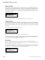
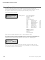
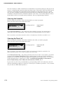
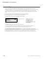
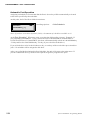
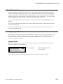
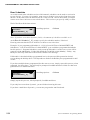
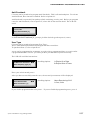
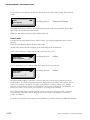
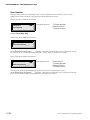
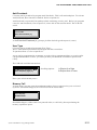
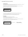
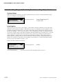
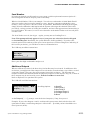
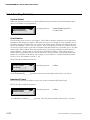
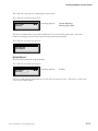
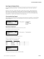
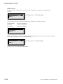
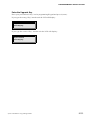
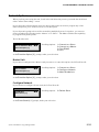
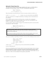
PC/VDT PROGRAMMING - PORT CONFIGURATION
Relay Type
When a valid code is entered, the Port’s door relay may be activated. How it will be activated
is what we are interested in here.
There are two modes of relay activation: Momentary and Latching. In Momentary mode, the
relay closes for a programmed time period ranging from 1 to 255 seconds. In Latching mode,
the relay toggles its state. In other words, if the relay was on, it turns off... if the relay was off,
it turns on.
Note: The main relay time for a two-door System 2 (2016) is 65535 seconds (18.2 hours).
The VDT will display the instructions:
1=Latching,2=Momentary
Relay Type [2]
At the Relay Type [ 2 ] prompt, pick the desired option followed by ENTER.
Momentary Time
If you chose momentary, the VDT will display the instructions:
Use 1 thru 255 Seconds
Momentary Time [__5]
At the Momentary Time [ __5] prompt, enter your selection followed by ENTER. If
you selected Latching, you are finished, you do not need to enter a Latching Time. As you can
see, you do not need to enter three digits here. A 5 is all that is needed to program this Port /
door for five seconds.
Automatic Port Operation
Assigning a schedule to a Port means that the Port's door relay will be automatically activated
at the times specified by that schedule.
At this point, the VDT will display the instructions:
Use 0 thru 6
0=No Schedule
Port Schedule [_0]
Note: If you have a two-door System 2 (2016) , the amount of schedules available is 16.
At the Port Schedule [_0] prompt, enter your selection followed by ENTER.
Example: If you programmed Schedule #1 - Cell #1 for an ON Time of 09:00 MTWTF and
Schedule #1 - Cell #2 an OFF Time of 17:00 MTWTF, this door will automatically unlock at 9:00
AM Monday - Friday and Lock at 5:00 PM Monday - Friday (if you select Port Schedule 1).
If you wish the door to be locked 24 hours a day, seven days of the week either press 0 and
ENTER or just ENTER. No schedule will be assigned to this door.
After you are finished assigning this Port Schedule, the unit will return to the main menu. If
you have additional doors, you must enter Option #5 again to program these ports.
9-186
System 2 Installation / Programming Manual
PC/VDT PROGRAMMING - PORT CONFIGURATION
Selecting Any Card/Chip Mode
In this mode, any Corby Cards or Data Chips will activate any of the doors, regardless if the
card or chip is programmed into the unit. All someone needs is a Corby card or data chip and
the door can be accessed. This should only be used in minimal security applications where
security is not strictly enforced. In other words, this can be classified as an unlimited users
mode.
This should only be programmed if you desire the above outcome. Otherwise, skip over this
part of the program.
The VDT will display the following instructions:
WARNING!
This Mode Allows ANY
Card/Chip Access!
Press Any Key
The VDT will display the following instructions:
1=ANY Card/Chip Mode
2=Normal Mode
0=Quit
Select Mode [2]
You are given the opportunity to change your mind or verify your initial selection. If you select
2 “Normal Mode”, you will return on-line and the system will set the port to normal mode.
If you select 1 “ANY Card/Chip Mode” you will see the following prompt:
1=Yes,2=No
Are You Sure? [2]
After making your selection, you will return to the main menu.
System 2 Installation / Programming Manual
9-187
PC/VDT PROGRAMMING - AUXILIARY OUTPUTS
Program Aux Outputs
(Option #6)
A two-door System 2 provides four general-purpose auxiliary outputs. Two of these outputs
are
C Form Auxiliary Relays, and two are voltage outputs. The Voltage Outputs are open-collector
transistors. This means that, when activated, the transistors create a “short” between their
terminal connection and System negative. The maximum current that can pass through the
Voltage Output’s transistors is 50mA.
If the Second Door was activated, any of these four outputs can be programmed to be activated
by a valid code entry, as we will discuss in Enrolling Single Users. In addition, they can be
activated from any of the time schedules or from a System event.
Selecting the Output
The VDT will display the instructions:
Enter Aux Output
1=Aux Relay 1
2=Aux Relay 2
3=Voltage Output 1
4=Voltage Output 2
Output [1]
At the Output [ 1 ] prompt, enter your selection followed by ENTER.
Output Mode
An output may be triggered by a valid code or other events which we will get to later. How it
will be triggered is what we are interested in here.
The are two modes of output activation: Momentary and Latching. In Momentary mode, the
output is activated for a programmed period of from 1 to 255 seconds. In Latching mode, the
output toggles its state. In other words, if the output is on, it turns off. Likewise, if the output
is off, it turns on.
The VDT will display the instructions:
1=Latching,2=Momentary
Output Mode [2]
At the Output Mode [ 2 ] prompt, pick the desired option followed by ENTER. If you
select Latching, you are finished, you do not need to enter a Latching Time.
Momentary Time
If you chose momentary, the VDT will display the instructions:
Enter 1 thru 255 Seconds
Momentary Time [__2]
At the Momentary Time [_ _ 2] prompt, enter your selection followed by ENTER.
You do not need to enter three digits here. A two is all that is needed to program this Port /
Door for two seconds.
9-188
System 2 Installation / Programming Manual
PC/VDT PROGRAMMING - AUXILIARY OUTPUTS
Trigger Event
As we mentioned above, an output can be triggered by a System event. Example: If you are
programming Auxiliary Relay #1, and want it to activate when an invalid code is used at one of
the readers, select 11 - Inv Code. You can now wire this Relay to a light, bell, whistle, etc. and
each time there is an invalid code Auxiliary Relay #1 will activate.
If you do not wish these outputs to activate from any System event, press 0.
At this point, you may select which event, if any, will trigger this output.
The VDT will display the instructions:
1=System Reset
2 = AC Off
3 = AC On
4 = Memory Clear
5 = Relay Override
6 = Door Ajar
7 = Door Closed
8 = Forced Entry
9 = Valid User
10= Inv
11 = Inv Code
12 = PIN Error
13 = Sched Error
14 = Request To Exit
15 = Unknown Event
16 = AP Error
17 = Door Perm
18 = Daylight Savings
19 = Powerup
20 = Zone On
21 = Zone Off
Enter (0 for None) [_0]
At the Event (0 for None) [_ 0] prompt, enter your selection followed by ENTER.
System 2 Installation / Programming Manual
9-189
PC/VDT PROGRAMMING - AUXILIARY OUTPUTS
As discussed above, various system events can be assigned to operate auxiliary outputs. Some
events will trigger outputs only locally on the unit on which they occur, while other events will trigger
outputs both on the unit they occur and on the master as well. Bear in mind, however, that the unit on
which an event occurs and the master may be one in the same unit (i.e., it happened on the master
and not on a slave).
If programmed to trigger outputs, events deemed important to system reliability or security (in our
opinion here at Corby) trigger both on the unit on which they occur and on the master. Other “lesser”
events trigger outputs only locally on the unit on which they occur.
The table below specifies the behavior of each of the triggerable events.
Event Type
Local Only
Both Master and Slave
System Reset
X
AC Off
X
AC On
X
Door Ajar
X
Door Closed
X
Forced Entry
Valid User
X
X
Inv
X
PIN Error
X
Sched Error
X
Request to Exit
X
AP Error
X
Door Perm
X
Mem Clear
X
Zone On
X
Zone Off
X
Slave Down
X
Net Noise
X
9-190
System 2 Installation / Programming Manual
PC/VDT PROGRAMMING - AUXILIARY OUTPUTS
Automatic Output Operation
This is the point at which you may assign a schedule to the output... provided you have
installed a two-door System 2 (2016). The VDT will display the instructions:
Use 0 thru 6
0=No Schedule
Port Schedule [_0]
Note: If you have a two-door Syst em 2 (2016), the amount schedules available is 16.
At the Port Schedule [ _ 0 ] prompt, enter your selection followed by ENTER.
The output will activate as configured (momentary or latching) at the start and end time of a
time schedule.
If you wish this output to be inactive 24 hours a day, seven days of the week (unless
programmed to trigger from any of the available events) either press 0 and ENTER or just
ENTER. No schedule will be assigned to this output.
If you selected any of these Outputs to trigger from a schedule and you have not activated the
Second Door the VDT will display:
Option Not Active
Install in Option 13
Press Any Key
Note: Although the display states the Option is Not Active, the output(s) have been assigned to the
selected schedule. However, it will not activate until the Second Door has been turned ON. Proceed to
Option #13 to turn this Option ON.
The unit assigns this output to the schedule for those customers who wish to upgrade a one-door system
(2003) to a two-door system (2016) in the future, but do not wish to re-program the outputs.
After you are finished programming the Schedule section, the VDT will display the instructions:
Enter Aux Output
1=Aux Relay 1
2=Aux Relay 2
3=Voltage Output 1
4=Voltage Output 2
Output [1]
At the Output [ 1 ] prompt, enter your next selection followed by ENTER.
If you are finished press 0.
If you are operating the System 2 in network mode, and you assign a trigger event to a output,
that function operates locally to each unit in the network. This means that if you, for example,
assign Aux Relay #1 to trigger on a door ajar, Aux Relay #1 on the master will trigger if the
door ajar occurs on the master; Aux Relay #1 on Slave #1 will trigger if the door ajar occurs on
Slave #1, etc. This, of course, holds true for any other system event.
System 2 Installation / Programming Manual
9-191
PC/VDT PROGRAMMING - ANTI-PASSBACK
Anti-Passback
(Option #7)
You must have the Second Door option activated to activate this feature.
If the VDT displays: Option Not Active!
Install in Option 13
Press Any Key, go to Option 13 and follow the instructions to activate the Second
Door.
Anti-Passback is a powerful security tool. Before we look at how to program AntiPassback, we'll discuss what it is.
Anti-Passback requires that a user must enter via Port 1 and exit through Port 2. Typically
this option is used in conditions where the Management does not want an individual to enter
and then "pass" their Card "back" to another individual (under the door, through a window,
whatever) therefore allowing an unauthorized entry. It is required when using anti-passback
that Port 1 and Port 2 control a single door.
Coupled with other security measures, anti-passback is an effective way to keep absolute
track of who comes and goes. Another effective way to use this option is at parking lots or
garages where the exit is separated from the entrance.
There are two types of Anti-Passback: Hard and Soft. Hard Anti-Passback means there is
never any forgiveness. You must exit an area before you can enter it again, in strict
alternation, for all time, period.
With Soft Anti-Passback enabled, all Anti-Passback restrictions are "forgiven" and reset to
their initial working state at sometime during the day. So, if you sneak out the door with
another employee, you can re-enter the door again... after the forgive time has passed. Let’s
look at this in greater detail.
Hard or Soft Anti-Passback
The VDT will display the instructions:
1=Hard,2=Soft
0=Quit
Enter AP Type [1]
At the Enter AP Type [1] prompt enter 1 for Hard AP or 2 for Soft AP.
If you choose 1 your finished. If you choose 2 you must set the Forgive Time.
Forgive Time
The VDT will display the following instructions:
Use Military hh:mm
Set Forgive Time [00:00]
If you select 23:00 as your forgive time (11:00 PM), the System will automatically reset the
Anti-Passback feature at 11:00 PM.
If you are using the System 2 in its network mode, anti-passback works locally to each unit.
This means that if a user enters on port one of the master, that user must exit through port 2 of
the master -- not port 2 of any other unit. The same is true for Slave #1, #2, and all other
slaves.
9-192
System 2 Installation / Programming Manual
PC/VDT PROGRAMMING - ADD/CHANGE KEYPAD CODES
Add or Change User
(Option #8)
You must first Select Card Type (Option #4) - if using cards, and Port Configuration (Option
#5) before adding or changing any users. Why? Well the System default is for a Keypad Only,
a momentary time of five seconds, and no time schedule. If you are using Readers, the System
will not request your Card Number. Instead it will request your code number. If you are using
Keypads and these defaults are OK, you do not need to Program the Ports.
If you are using Keypads exclusively, follow the instructions under Enrolling Keypad Codes.
(Below).
If you are using Wiegand, Proximity, Bar Code or Mag-Stripe Readers, follow the instructions
under Enrolling Cards
If you are using Data Chips, (which are not sequentially numbered), follow the instructions
under Enrolling Data Chips.
Enrolling Keypad Codes
In this option, you'll specify a user’s code, the door(s) the user may access, when the user may
access these doors, which outputs will be activated, whether the user is subject to AntiPassback, and if the user is Permanent or Temporary. Whew, that’s a lot of information, but
we’ll cover each item in detail.
System Status
When this Option is entered, you will be told how many users are enrolled and how many user
slots are available for programming:
Users Enrolled 0000
Users Remaining 0413
1=Yes,2=No
Want to Continue? [1]
If you wish to enroll users press 1 (YES) and ENTER, otherwise, enter 2 for No.
User Numbers
The first thing to do is enter a u s e r number, not the code number. The user number uniquely
identifies a user and can be thought of as an employee number. In fact, many installers use a
company’s existing employee numbers as user numbers. When the user enters a code, and this
event is printed or displayed on the VDT, it is not the code number that is displayed to identify
the user but the user number. Why? If Keypads are used, it would be a breach of security to
print a user's code where unauthorized individuals may eventually see it.
The VDT will display the instructions:
Use Up to 4 Digits
0=Quit
Enter User [___0]
At the Enter User [_ _ _ 0] prompt, enter the desired number followed by ENTER.
If you wish to select user number 1 simply press 1 and ENTER. You do not need to enter all
four digits here. Remember, this is the user number not the Code Number.
System 2 Installation / Programming Manual
9-193
PC/VDT PROGRAMMING - ADD/CHANGE KEYPAD CODES
Door Number
This part may seem a bit confusing, so be sure to read this section entirely. Here you are
instructed to enter the door(s) this person will be allowed to access.
The VDT will display the instructions:
Enter Door #
To Grant Access
Reenter Door #
To Deny Access
Press Any Key
Simply Press Any Key.
The VDT will display the instructions:
00
Enter Door (0=Done) [__]
At the Enter Door (0=Done) [ _ _ ] prompt, enter the first door this user is
allowed to access. Let’s say user #1 is allowed access to doors 1, and 3. Enter 1 and press
ENTER.
The VDT will display the instructions:
01
Enter Door (0=Done) [__]
The first line of the VDT will display the door(s) this user is allowed to access.
At the Enter Door (0=Done) [_ _] prompt, enter the next door this user is allowed
to access. If we stick with the sample we would enter a 3 and press ENTER.
9-194
System 2 Installation / Programming Manual
PC/VDT PROGRAMMING - ADD/CHANGE KEYPAD CODES
The VDT will display the instructions:
01 03
Enter Door (0=Done) [__]
The first line of the VDT will display the door(s) this user is allowed to access.
At the Enter Door (0=Done) [ _ _ ] prompt, enter the next door this user is
allowed to access. When you are finished press 0 and ENTER. If you wish to change the door
permission at any time, reenter the number to deny access to a specified door.
Example: If you wish to “take door #3 permission away” from this user, enter door 3 again and
the permission will be denied.
If you select Port #3 or greater and you do not have this System set-up for networking, the
VDT will display:
Error!
Entry Out of Range!
Press Any Key
To enable more than two doors, the Networking Option needs to be installed. Proceed to
Option #13 for installation instructions.
When you are finished entering door numbers press 0.
User Codes
If, and only if, you have selected keypads as your input device (back in options 4 and 5), you
will be prompted to enter a Keypad code of nine digits or less. User can have varying code
lengths. One user can have a five digit code, another a six digit code, and yet another a three
digit code.
The System ignores any leading zeros. In other words, you cannot program a code of
02306. The System ignores the first zero and the user will only have a four digit code of
2306. As you can see zeros can be used within a code.
At this point, the VDT will display the following instructions:
Enter Keypad Code
Up to 9 Digits
No Leading Zeros
0=Quit
Enter Code [_________]
If you were successful in entering your code, proceed to Entering Additional Outputs.
System 2 Installation / Programming Manual
9-195
PC/VDT PROGRAMMING - ADD/CHANGE KEYPAD CODES
If you attempt to enter a code which is already used, you will see the following prompt:
Press Any Key
Duplicate Code!
Additional Outputs
When a valid code is entered, the door relay for that Port will, by default, be activated. In
addition to this activation of the door relay, you might want other outputs to be activated as well
to, for example, sound an alarm, trip a dialer, or send some other signal. There are four such
outputs from which to choose. The Program Aux Outputs section of this manual details the
physical properties of the outputs. Any, all, or none of these outputs may be activated by a user,
if the Second Door has been activated.
Refer to Option #13 to purchase this option.
The VDT will display the instructions:
Assign These Output(s)
To User ID
1=Aux Relay 1
2=Aux Relay 2
3=Voltage Output 1
4=Voltage Output 2
0=None
Outputs [----]
At the Outputs [----] prompt, enter the desired output(s), if any, then press ENTER.
Example: If you are programming the code 12345 and select Outputs 1 and 3, each time the
code 12345 is used the door will open and Aux Relay 1 and Voltage Output 1 will trigger . . .
provided you have installed a two-door System 2 (2016).
If you are operating the System 2 in its networking mode, outputs triggered by a valid user
operate locally to each unit. In other words, if our valid user who is programmed to trigger
outputs 1 and 3 enters at a door on the master, the master’s outputs 1 and 3 will be triggered. If
this same user enters at a door on Slave #1, outputs 1 and 3 on Slave #1 will be triggered -- and
so on for all other units on the network.
If you select any of these Outputs and you have not activated the Second Door the VDT will
display:
Install in Option 13
Option Not Active
Press Any Key
Note: Although the display states the Option is Not Active, the output(s) have been assigned to the selected schedule.
However, it will not activate until the Second Door has been turned ON. Proceed to Option #13 to turn this Option ON.
The unit assigns this output to the user codes for those customers who wish to upgrade a one-door system (2003) to a twodoor system (2016) in the future, but do not wish to re-program the outputs.
9-196
System 2 Installation / Programming Manual
PC/VDT PROGRAMMING - ADD/CHANGE KEYPAD CODES
Door Schedules
As we discussed in the schedule section of this manual, schedules can be used to restrict the
access of users. You may, for example, want a user to be able to access the front door from
08:00 to 18:00, and access the back door from 17:00 to 23:00. On the other hand, you might
want a user to have 24-hour access to both doors. This is where you specify what you want.
The VDT will display the instructions
Use 0 thru 8
0=None
Door 01 Schedule [_0]
Note: If you have a two-doo r System 2 (2016), the amount of schedules available is 16.
At the Door 01 Schedule [ _ 0 ] prompt, specify the schedule number, if desired.
Entering a 0 means that this user will have 24-hour access to the door.
Example: If you programmed Schedule #1 - Cell #1 for an ON Time of 08:00 MTWTF and
Schedule #1 - Cell #2 an OFF Time of 18:00 MTWTF (you would have programmed schedules
back in option 3 - Program Schedules), and you assign Schedule #1 to this user, access will be
granted at 8:00 AM Monday - Friday and denied after 6:00 PM (18:00) Monday - Friday. Any
attempt to enter any other time will result in schedule error message.
If Schedule #1 also has holidays programmed into it, the person will be granted or denied
access during the holiday dates. This depends on whether the Holiday was programmed for ON
or OFF.
If you have multiple doors programmed for this user to access, simply repeat this process, when
prompted, for these doors. You will only be prompted for additional doors if this user has been
granted access to additional doors.
Use 0 thru 8
0=None
Door 02 Schedule [_0]
Simply repeat this process, when prompted, for additional doors.
If you only have a one door System 2, you are finished entering this user.
If you have a multi-door System 2, you can now program the Anti-Passback.
System 2 Installation / Programming Manual
9-197
PC/VDT PROGRAMMING - ADD/CHANGE KEYPAD CODES
Anti-Passback
(You may not be permitted to program Anti-Passback).
To activate Anti-Passback, Door 2 must be activated. Refer to Option #13.
Anti-Passback is a powerful, but perhaps a little confusing, security tool. Before you program
a user for Anti-Passback, refer to Option #7, where this is discussed in detail. The VDT will
display:
1=Yes,2=No
Enter Anti-Passback
At the Enter Anti-Passback [2] prompt, pick the desired type then press ENTER.
User Type
(You may not be permitted to program User Type).
This is a Premium Option which is packaged with the second door.
To purchase Door 2, refer to Option #13.
A user can be programmed as permanent, to expire after a programmed date, or to expire after
a programmed number of uses - provided you have activated this option from Corby.
The VDT will display the instructions:
0=Make User Permanent
1=Expire On a Date
2=Expire After # Times
Enter Temporary Type [0]
Enter your selection and press ENTER.
After you have successfully entered a user, the current System status will be displayed.
User Enrolled 0001
Users Remaining 0412
1=Yes,2=No
Want to Continue? [1]
If you wish to program another user press 1. If you are finished programming users, press 2.
9-198
System 2 Installation / Programming Manual
PC/VDT PROGRAMMING - ADD/CHANGE CARDS
Enrolling Cards
In this option, you'll specify a user’s card, the door(s) the user may access, when the user may
access these doors, which outputs will be activated, whether the user is subject to AntiPassback, and if the user is Permanent or Temporary.
System Status
When this Option is entered, you will be told how many users are enrolled and how many user
slots are available for programming:
Users Enrolled 0000
Users Remaining 0413
1=Yes,2=No
Want to Continue? [1]
If you wish to enroll users press 1 and ENTER.
User Numbers
The first thing to do is enter a u s e r number, not the card number. This number uniquely
identifies a user and can be thought of as an employee number. After using your card, the
event is printed or displayed on the VDT, it is not the code number that is displayed to identify
the user but the user number. Why? This number may be quite long, and take too much space to
print or display.
The VDT will display the instructions:
Use Up to 4 Digits
0=Quit
Enter User [___0]
At the Enter User [ _ _ _ 0 ] prompt, enter the desired number followed by a
ENTER. If you wish to select user number 1 simply press 1 and ENTER. You do not need to
enter all four digits here. Remember, this is the user number not the Card Number.
System 2 Installation / Programming Manual
9-199
PC/VDT PROGRAMMING - ADD/CHANGE CARDS
Door Number
This part may seem a bit confusing, so be sure to read this section entirely. Here you are
instructed to enter the door(s) this person will be allowed to access.
The VDT will display the instructions:
Enter Door #
To Grant Access
Reenter Door #
To Deny Access
Press Any Key
Simply Press Any Key .
The VDT will display the instructions:
00
Enter Door (0=Done) [__]
At the Enter Door (0=Done) [ _ _ ] prompt, enter the first door this user is
allowed to access. Let’s say user #1 is allowed access to doors 1, and 3. Enter 1 and press
ENTER.
The VDT will display the instructions:
01
Enter Door (0=Done) [__]
The first line of the VDT will display the door(s) this user is allowed to access.
At the Enter Door (0=Done) [ _ _ ] prompt, enter the next door this user is
allowed to access. If we stick with the sample we would enter a 3 and press ENTER.
The VDT will display the instructions:
01 03
Enter Door (0=Done) [__]
The first line of the VDT will display the door(s) this user is allowed to access.
At the Enter Door (0=Done) [_ _] prompt, enter the next door this user is allowed
to access. When you are finished press 0 and ENTER. If you wish to change the door
permission at any time, reenter the number to deny access to a specified door.
Example: If you wish to “take door #3 permission away” from this user, enter door 3 again and
the permission will be denied.
9-200
System 2 Installation / Programming Manual
PC/VDT PROGRAMMING - ADD/CHANGE CARDS
If you select Port #3 and you do not have this System set-up for networking, the VDT will
display:
Error!
Entry Out of Range!
Press Any Key
To enable more than two doors, the Networking Option needs to be installed. Proceed to
Option #13 for installation instructions.
When you are finished entering door numbers press 0.
User Cards
If either Port is programmed for use with a reader, you will be prompted to enter a Card
Number.
Enter the Card Number shown on the Card’s label.
At this point, the VDT will display one of the following set of instructions:
If you chose card type 2 (Mag or Bar Code) the VDT will display:
Enter Number
0=Quit
Enter Card [00000_____]
If you chose card type 5 (16 Digit Mag, Bar Code) the VDT will display:
Enter Number
0=Quit
Enter Card [________________]
Wiegand and Proximity Cards have a facility code which needs to precede the five digit
Card Number. If you are programming either Wiegand or Proximity Cards and the facility
code is, for example, 07 and the five digit Card Number is 00024, simply enter 700024.
You now actually have a six digit Card Number - the facility code and the Card Number. If
the facility code is 10 or above, you will have a seven digit Card Number.
Bar Code and Mag-Stripe Readers do not require you to enter a facility code. If you are
programming either Bar Code or Mag-Stripe Cards and the code happens to be 00024,
simply enter 00024.
If you were successful in entering your Card Number, proceed to Entering Additional Outputs.
Duplicate Code!
If you happen to attempt to enter a Card Number which is already used, you will see the
prompt:
Press Any Key
Duplicate Code!
If this happens, simply choose another code or delete the existing code.
For more information, see Option 10 - Delete Users.
System 2 Installation / Programming Manual
9-201
PC/VDT PROGRAMMING - ADD/CHANGE CARDS
Additional Outputs
When a valid card is entered, the door relay for that Port may be activated. In addition to this
activation, you might want other outputs to be activated to sound an alarm, trip a dialer, or send
some other signal. There are four such outputs from which to choose. The Program Aux
Outputs section of this manual details the physical properties of the outputs. Any, all, or none of
these outputs may be activated by a user, if the Second Door is activated.
Refer to Option #13 to activate this option.
The VDT will display the instructions:
Assign These Output(s)
To User ID
1=Aux Relay 1
2=Aux Relay 2
3=Voltage Output 1
4=Voltage Output 2
0=None
Outputs [----]
At the Outputs [----] prompt, enter the desired output(s), if any, then press ENTER.
Example: If you are programming the code 12345 and select Outputs 1 and 3, each time the
code 12345 is used the door will open and Aux Relay 1 and Voltage Output 1 will trigger...
provided you have installed a two-door System 2 (2016).
If you select any of these Outputs and you have not activated the Second Door the VDT will
display:
Option Not Active!
Install in Option 13
Press Any Key
Note: Although the display states the Option is Not Active, the output(s) have been assigned to the selected schedule.
However, it will not activate until the Second Door has been turned ON. Proceed to Option #13 to turn this Option ON.
The unit assigns this output to the user codes for those customers who wish to upgrade a one-door system (2003) to a twodoor system (2016) in the future, but do not wish to re-program the outputs.
9-202
System 2 Installation / Programming Manual
PC/VDT PROGRAMMING - ADD/CHANGE CARDS
Door Schedules
As we discussed in the schedule section of this manual, schedules can be used to restrict the
access of users. You may, for example, want a user to be able to access the front door from
08:00 to 18:00, and access the back door from 17:00 to 23:00. On the other hand, you might
want a user to have 24-hour access to both doors. This is where you specify what you want.
The VDT will display the instructions
Use 0 thru 8
0=None
Door 01 Schedule [_0]
Note: If you have a two-door System 2 (2016), the amount of schedules available is 16.
At the Door 01 Schedule [_0] prompt, specify the schedule number, if desired.
Entering a 0 means that this user will have 24-hour access to the door.
Example: If you programmed Schedule #1 - Cell #1 for an ON Time of 08:00 MTWTF and
Schedule #1 - Cell #2 an OFF Time of 18:00 MTWTF, and you assign Schedule #1 to this user,
access will be granted at 8:00 AM Monday - Friday and denied after 6:00 PM (18:00) Monday Friday. Any attempt to enter any other time will result in an invalid entry.
If Schedule #1 also has holidays programmed into it, the person will be granted or denied
access during the holiday dates. This depends on whether the Holiday was programmed for ON
or OFF.
If you have multiple doors programmed for this user to access, simply repeat this process, when
prompted, for these doors. You will only be prompted for additional doors if this user has been
granted access to additional doors.
Use 0 thru 8
0=None
Door 02 Schedule [_0]
Simply repeat this process, when prompted, for additional doors.
If you only have a one door System 2, you are finished entering this user.
If you have a multi-door System 2, and have purchase the Anti-Passback Premium Option, you
can now program the Anti-Passback.
System 2 Installation / Programming Manual
9-203
PC/VDT PROGRAMMING - ADD/CHANGE CARDS
Anti-Passback
(You may not be permitted to program Anti-Passback).
To activate Anti-Passback, Door 2 must be installed. Refer to Option #13.
Anti-Passback is a powerful, but perhaps a little confusing, security tool. Before you program
a user for Anti-Passback, refer to Option #7, where this is discussed in detail. The VDT will
display:
1=Yes,2=No
Enter Anti-Passback
At the Enter Anti-Passback [2] prompt, pick the desired type then press ENTER.
User Type
(You may not be permitted to program User Type).
This is a Premium Option which is packaged with the second door.
To purchase Door 2, refer to Option #13.
A user can be programmed as permanent, to expire after a programmed date, or to expire after
a programmed number of uses - provided you have purchased the second door from Corby.
The VDT will display the instructions:
0=Make User Permanent
1=Expire On a Date
2=Expire After # Times
Enter Temporary Type [0]
Enter your selection and press ENTER.
Memory Full
At some point, you may enter the maximum number of users supported on your version of
System 2. Should this happen, the VDT will display the instructions:
Press Any Key
No More Room!
Should this happen, either remove any unused codes, or call Corby about purchasing the
memory expansion option.
After you have successfully entered a user, the current System status will be displayed.
Users Enrolled 0001
Users Remaining 0412
1=Yes,2=No
Want to Continue? [1]
If you wish to program another user press 1.
If you are finished programming users, press 2.
9-204
System 2 Installation / Programming Manual
PC/VDT PROGRAMMING - ADD/CHANGE DATA CHIPS
Enrolling Data Chips
In this option, you'll specify a user’s chip, the door(s) the user may access, when the user may
access these doors, which outputs will be activated, whether the user is subject to AntiPassback, and if the user is Permanent or Temporary.
System Status
When this Option is entered, you will be told how many users are enrolled and how many user
slots are available for programming:
Users Enrolled 0000
Users Remaining 0413
1=Yes,2=No
Want to Continue? [1]
If you wish to enroll users press 1 and ENTER.
User Numbers
The first thing to do is enter a u s e r number, not the chip number. This number uniquely
identifies a user and can be thought of as an employee number. When the user touches a chip,
and this event is printed or displayed on the VDT, it is not the chip number that is displayed to
identify the user but the user number. Why? This number may be quite long, and take too much
space to print or display.
The VDT will display the instructions:
Use Up to 4 Digits
0=Quit
Enter User [___0]
At the Enter User [_ _ _0] prompt, enter the desired number followed by a ENTER.
If you wish to select user number 1 simply press 1 and ENTER. You do not need to enter all
four digits here. Remember, this is the user number not the Chip Number.
System 2 Installation / Programming Manual
9-205
PC/VDT PROGRAMMING - ADD/CHANGE DATA CHIPS
Door Number
This part may seem a bit confusing, so be sure to read this section entirely. Here you are
instructed to enter the door(s) this person will be allowed to access.
The VDT will display the instructions:
Enter Door #
To Grant Access
Reenter Door #
To Deny Access
Press Any Key
Simply Press Any Key .
The VDT will display the instructions:
00
Enter Door (0=Done) [__]
At the Enter Door (0=Done) [ _ _ ] prompt, enter the first door this user is
allowed to access. Let’s say user #1 is allowed access to doors 1, and 3. Enter 1 and press
ENTER.
The VDT will display the instructions:
01
Enter Door #
To Grant Access
Reenter Door #
To Deny Access
Enter Door (0=Done) [__]
The first line of the VDT will display the door(s) this user is allowed to access.
At the Enter Door (0=Done) [_ _] prompt, enter the next door this user is allowed
to access. If we stick with the sample we would enter a 3 and press ENTER.
The VDT will display the instructions:
01 03
Enter Door #
To Grant Access
Reenter Door #
To Deny Access
Enter Door (0=Done) [__]
The first line of the VDT will display the door(s) this user is allowed to access.
At the Enter Door (0=Done) [_ _] prompt, enter the next door this user is allowed
to access. When you are finished press 0 and ENTER. If you wish to change the door
permission at any time, reenter the number to deny access to a specified door.
Example: If you wish to “take door #3 permission away” from this user, enter door 3 again and
the permission will be denied.
9-206
System 2 Installation / Programming Manual
PC/VDT PROGRAMMING - ADD/CHANGE DATA CHIPS
If you select Port #3 and you do not have this System set-up for networking, the VDT will
display:
Error!
Entry Out of Range!
Press Any Key
To enable more than two doors, the Networking Option needs to be installed. Proceed to
Option #13 for installation instructions.
When you are finished entering door numbers press 0.
User Chips
If either Port is programmed for Data Chip, you will be prompted to enter a Data Chip Number.
If using Data Chips, you can either touch the Data Chip to the test point at the upper right hand
corner on the System 2 circuit board or use the optional “Data Chip wand reader”.
At this point, the VDT will display the following instructions:
Enter Number
Touch DataChip or
Enter Chip Number
Use Bckspc to correct
0 to Quit
Enter Chip
Be sure to “List Users” (Option 11 - Reports) after you have programmed all you Data Chips
into the System. If you wish to re-enter Data Chips, and you do not have them “in-hand”, you
must have the full 16-digit code. This code will print when you List Users. Since the code
contains alphanumeric characters a PC or VDT is also needed to re-enter these chips. If you
were successful in entering your Chip, proceed to Entering Additional Outputs.
Duplicate Code!
If you happen to attempt to enter a Chip which is already used, you will see the prompt:
Press Any Key
Duplicate!
If this happens, simply select another chip or delete the existing chip.
For more information, see Option 10 - Deleting Users.
System 2 Installation / Programming Manual
9-207
PC/VDT PROGRAMMING - ADD/CHANGE DATA CHIPS
Additional Outputs
When a valid Data Chip is entered, the door relay for that Port may be activated. In addition to
this activation, you might want other outputs to be activated to sound an alarm, trip a dialer, or
send some other signal. There are four such outputs from which to choose. The Program Aux
Outputs section of this manual details the physical properties of the outputs. Any, all, or none of
these outputs may be activated by a user, if the Second Door is activated.
Refer to Option #13 to activate this option.
The VDT will display the instructions:
Assign These Output(s)
To User ID
1=Aux Relay 1
2=Aux Relay 2
3=Voltage Output 1
4=Voltage Output 2
0=None
Outputs [----]
At the Outputs [----] prompt, enter the desired output(s), if any, then press ENTER.
Example: If you are programming the code 12345 and select Outputs 1 and 3, each time the
code 12345 is used the door will open and Aux Relay 1 and Voltage Output 1 will trigger...
provided you have installed a two-door System 2 (2016).
If you select any of these Outputs and you have not activated the Second Door the VDT will
display:
Option Not Active!
Install in Option 13
Press Any Key
Note: Although the display states the Option is Not Active, the output(s) have been assigned to the selected schedule.
However, it will not activate until the Second Door has been turned ON. Proceed to Option #13 to turn this Option ON.
The unit assigns this output to the user codes for those customers who wish to upgrade a one-door system (2003) to a twodoor system (2016) in the future, but do not wish to re-program the outputs.
9-208
System 2 Installation / Programming Manual
PC/VDT PROGRAMMING - ADD/CHANGE DATA CHIPS
Door Schedules
As we discussed in the schedule section of this manual, schedules can be used to restrict the
access of users. You may, for example, want a user to be able to access the front door from
08:00 to 18:00, and access the back door from 17:00 to 23:00. On the other hand, you might
want a user to have 24-hour access to both doors. This is where you specify what you want.
The VDT will display the instructions
Use 0 thru 8
0=None
Door 01 Schedule [_0]
Note: If you have a two-door System 2 (2016) , the amount of schedules available is 16.
At the Door 01 Schedule [_0] prompt, specify the schedule number, if desired.
Entering a 0 means that this user will have 24-hour access to the door.
Example: If you programmed Schedule #1 - Cell #1 for an ON Time of 08:00 MTWTF and
Schedule #1 - Cell #2 an OFF Time of 18:00 MTWTF, and you assign Schedule #1 to this user,
access will be granted at 8:00 AM Monday - Friday and denied after 6:00 PM (18:00) Monday Friday. Any attempt to enter any other time will result in an invalid entry.
If Schedule #1 also has holidays programmed into it, the person will be granted or denied
access during the holiday dates. This depends on whether the Holiday was programmed for ON
or OFF.
If you have multiple doors programmed for this user to access, simply repeat this process, when
prompted, for these doors. You will only be prompted for additional doors if this user has been
granted access to additional doors.
Use 0 thru 8
Door 02 Schedule [_0]
Simply repeat this process, when prompted, for additional doors. If you only have a one door
System 2, you are finished entering this user.
If you have a multi-door System 2, and have purchase the Anti-Passback Premium Option, you
can now program the Anti-Passback.
Note: Cells must be programmed in a distinct order. Cell 1 must be programmed before Cell 2,
Cell 3 must be programmed before Cell 4, etc.
Anti-Passback
(You may not be permitted to program Anti-Passback).
To activate Anti-Passback, Door 2 must be installed. Refer to Option #13.
Anti-Passback is a powerful, but perhaps a little confusing, security tool. Before you program
a user for Anti-Passback, refer to Option #7, where this is discussed in detail. The VDT will
display:
1=Yes,2=No
Enter Anti-Passback
At the Enter Anti-Passback [2] prompt, pick the desired type then press ENTER.
System 2 Installation / Programming Manual
9-209
PC/VDT PROGRAMMING - ADD/CHANGE DATA CHIPS
User Type
(You may not be permitted to program User Type).
This is a Premium Option which is packaged with the second door.
To purchase Door 2, refer to Option #13.
A user can be programmed as permanent, to expire after a programmed date, or to expire after
a programmed number of uses - provided you have purchased the second door option from
Corby.
The VDT will display the instructions:
0=Make User Permanent
1=Expire On a Date
2=Expire After # Times
Enter Temporary Type [0]
Enter your selection and press #.
Memory Full
At some point, you may enter the maximum number of users supported on your version of
System 2. Should this happen, the VDT will display the instructions:
Press Any Key
No More Room!
Should this happen, either remove any unused codes, or call Corby about purchasing the
memory expansion option.
Bad Code!
If you enter a duplicate Data Chip code or do not enter a Data Chip number at all, you will see
this prompt:
Press Any Key
Bad Code!
The Data Chip should be re-entered. Go back to the beginning of this option and re-enter the
chip.
After you have successfully entered a user, the current System status will be displayed.
The VDT will display:
Users Enrolled 0001
Users Remaining 0412
1=Yes,2=No
Want to Continue? [1]
If you wish to program another user press 1.
If you are finished programming users, press 2.
9-210
System 2 Installation / Programming Manual
PC/VDT PROGRAMMING - BATCH ENROLL USERS
Batch Enroll Users (Option #9)
Batch enrollment allows you to enter large groups of similar users without entering specific
information for each and every user. In this option, you'll specify which doors a group of users
can access, when these users can access the doors, which outputs will be activated, and
whether these users are subject to Anti-Passback.
It is recommended that users be broken into groups having identical security levels. For
example, if there are 20 people who work in the computer operations area that all start work at
the same time, go through the same doors, etc.,etc., then you can automatically load them using
the Batch Enroll mode. Remember, that all details for all users must be identical for each
"group".
User numbers are assigned sequentially beginning with the first user number entered. It is
recommended that a method be devised prior to starting the code generation that will keep all
user groups separate. For example, management can have user numbers 1 through 20, office
personnel could have user numbers 100 through 199, etc. This method is recommended
because the security printer only prints the user number, NOT valid codes and/or Card
Numbers. If all personnel are separated into number groups, it is easy to identify users from
the printed copy.
All programming options specified when batch loading users apply to all the users in the batch.
Information only needs to be programmed once per batch.
If you are using Keypads exclusively, follow the instructions under Batch Enrolling Keypad
Codes.
If you are using Wiegand, Proximity, Bar Code or Mag-Stripe Readers, follow the instructions
under Batch Enrolling Cards.
If you are using Data Chips, (which are not sequentially numbered), follow the instructions
under Batch Enrolling Data Chips. If using Data Chips, you must manually load each Data
Chip into the System.
System 2 Installation / Programming Manual
9-211
PC/VDT PROGRAMMING - BATCH ENROLL KEYPAD CODES
Batch Enrolling Keypad Codes
System Status
When this Option is entered, you will be told how many user slots are enrolled and how many
users are available for programming:
Users Enrolled 0000
Users Remaining 0413
1=Yes,2=No
Want to Continue? [1]
User Number
The first thing to do is enter a user number. This number uniquely identifies a user and can be
thought of as an employee number. When the user enters a code and/or Card, and this event is
printed or displayed on the VDT, it is not the code number that is displayed to identify the user
but the user number. This is for two reasons. First, if Keypads are used, it would be a breach
of security to print a user's code where unauthorized individuals may eventually see it. Second,
when using Cards or Data Chips, this number may be quite long, and take too much space to
print or display. At this point we will enter the starting user number. This will be the user
number that is assigned to the first user in the batch. The System will sequentially add to this
number for each user in the batch. For example, if user number 1 is selected and the Number
of Users is 20, user numbers will be 1 - 20.
The VDT will display the instructions:
Use Up to 4 Digits
0=Quit
First User # [____]
At the First User # [_ _ _ _] prompt, enter the desired number and ENTER.
9-212
System 2 Installation / Programming Manual
PC/VDT PROGRAMMING - BATCH ENROLL KEYPAD CODES
Number of Users
Here you will specify the number of users you want to automatically Batch Load.
The VDT will display the instructions:
Use Up to 4 Digits
0=Quit
Number of Users [____]
At the Number of Users [_ _ _ _] prompt, enter the desired number and ENTER.
Door Number
This part may seem a bit confusing, so be sure to read this section entirely. Here you are
instructed to enter the door(s) these users will be allowed to access.
The VDT will display the instructions:
Enter Door #
To Grant Access
Reenter Door #
To Deny Access
Press Any Key
This display is for instructional purposes only. To continue, simply Press Any Key .
The VDT will display the instructions:
00
Enter Door (0=Done)
At the Enter Door (0=Done) [ _ _ ] prompt, enter the first door these users are
allowed to access. Let’s say this group is allowed access to doors 1, and 3. Enter 1 and press
ENTER.
The VDT will display the instructions:
01
Enter Door (0=Done)
The first line of the VDT will display the door(s) these users are allowed to access.
At the Enter Door (0=Done) [_ _] prompt, enter the next door these users are
allowed to access. If we stick with the sample we would enter a 3 and press ENTER.
System 2 Installation / Programming Manual
9-213
PC/VDT PROGRAMMING - BATCH ENROLL KEYPAD CODES
The VDT will display the instructions:
01 03
Enter Door (0=Done)
The first line of the VDT will display the door(s) this group is allowed to access.
At the Enter Door (0=Done) [_ _] prompt, enter the next door this group is
allowed to access. When you are finished press 0 and ENTER. If you wish to change the door
permission at any time, reenter the number to deny access to a specified door.
Example: If you wish to “take door #3 permission away” from these users, enter door 3 again
and the permission will be denied.
If you select Port #3 or greater and you do not have this System set-up for networking, the
VDT will display:
Error!
Entry Out of Range!
Press Any Key
To enable more than two doors, the Networking Option needs to be installed. Proceed to
Option #13 for installation instructions.
When you are finished entering door numbers press 0.
Seed Number
What is a Seed Number? Here’s an example: You select a seed number of 1000, Batch Enroll
200 users, and use the System for months or years. One day, someone accidentally erases
memory. Now everyone’s codes are erased. No problem! When Batch Enrolling Users again,
simply select Seed Number 1000 again, and the System will assign the identical codes it did
previously, saving you time of issuing new numbers, and users the aggravation of memorizing a
new code number. Of course, you need to be sure to write down the seed number and store it in
a safe place for future use.
The Seed Number must be four digits. Again, you may not use Leading Zero’s.
The VDT will display the instructions:
Use 4 Digits
Enter Seed # [____]
9-214
System 2 Installation / Programming Manual
PC/VDT PROGRAMMING - BATCH ENROLL KEYPAD CODES
Additional Outputs
When a valid code is entered, the door relay for that Port will be activated. In addition to this
activation, you might want other outputs to be activated to sound an alarm, trip a dialer, or send
some other signal. There are four such outputs from which to choose. The Port programming
section of this manual details the physical properties of the outputs. Any, all, or none of these
outputs may be activated by a valid code entry if the Second Door is activated. Refer to Option
#13 to purchase this option.
The VDT will display the instructions:
Assign These Output(s)
to User ID
1=Aux Relay 1
2=Aux Relay 2
3=Voltage Output 1
4=Voltage Output 2
0=None
Outputs [----]
At the Outputs [----] prompt, enter the desired output(s), if any, then press ENTER.
Example: If you select 1 (Auxiliary Relay 1) and 3 (Voltage Output 1) after someone in this
group enters a valid code or uses a valid Card the door will be activated and the Auxiliary Relay
#1 and Voltage Output #1 will activate.
If you select any of these Outputs and you have not activated the Second Door the VDT will
display:
Option Not Active
Install in Option 13
Press Any Key
Note: Although the display states the Option is Not Active, the output(s) have been assigned to the selected schedule.
However, it will not activate until the Second Door has been turned ON. Proceed to Option #13 to turn this Option ON.
The unit assigns this output to the schedule for those customers who wish to upgrade a one-door system (2003) to a twodoor system (2016) in the future, but do not wish to re-program the outputs.
System 2 Installation / Programming Manual
9-215
PC/VDT PROGRAMMING - BATCH ENROLL KEYPAD CODES
Door Schedules
As we discussed in the schedule section of this manual, schedules can be used to restrict the
access of users. You may, for example, want a group of users to be able to access the front
door from 08:00 to 18:00, and access the back door from 17:00 to 23:00. On the other hand, you
might want a group of users to have 24-hour access to both doors. This is where you specify
what you want.
The VDT will display the instructions :
Use 0 thru 6
0=None
Door 01 Schedule [_0]
Note: If you have a two-door System 2 (2016), the amount of schedules available is 16.
At the Door 01 Schedule [_0] prompt, specify the schedule number, if desired.
Entering a 0 means that these users will have 24-hour access to the door.
Example: If you programmed Schedule #1 - Cell #1 for an ON Time of 08:00 MTWTF and
Schedule #1 - Cell #2 an OFF Time of 18:00 MTWTF, and you assign Schedule #1 to this group
of users, access will be granted at 8:00 AM Monday - Friday and denied after 6:00 PM (18:00)
Monday - Friday. Any attempt to enter any other time will result in an invalid entry.
If Schedule #1 also has holidays programmed into it, these users will be granted or denied
access during the holiday dates. This depends on whether the Holiday was programmed for ON
or OFF.
If you have multiple doors programmed for these users to access, simply repeat this process,
when prompted, for these doors. You will only be prompted for additional doors if these users
have been granted access to additional doors.
Use 0 thru 8
0=None
Door 02 Schedule [_0]
Simply repeat this process, when prompted, for additional doors.
If you only have a one door System 2, you are finished entering these users.
If you have a multi-door System 2, and have purchase the 2nd Door Premium Option, you can
now program the Anti-Passback.
9-216
System 2 Installation / Programming Manual
PC/VDT PROGRAMMING - BATCH ENROLL KEYPAD CODES
Anti-Passback
(You may not be permitted to program Anti-Passback).
This is a Premium Option. To activate Anti-Passback, door 2 must be installed.
Refer to Option #13.
Anti-Passback is a powerful security tool. Before you program a group of users for AntiPassback, refer to Option #7, where this is discussed in detail.
The VDT will display the instructions:
1=Yes,2=No
Enter Anti-Passback? [2]
At the Enter Anti-Passback [2] prompt, pick the desired type then press ENTER.
If you have purchased the second door option, proceed to the next section.
If you did not purchase this option, you are finished entering these users.
Code Type
(You may not be permitted to program Code Type).
This is a Premium Option which is packaged with the second door.
To activate door 2, refer to Option #13.
Any user or group of users can be programmed as permanent, have their code expire after a
programmed date, or expire after a programmed number of uses.
The VDT will display the instructions:
0=Make User Permanent
1=Expire On a Date
2=Expire After # Times
Enter Temporary Type [0]
System 2 Installation / Programming Manual
9-217
PC/VDT PROGRAMMING - BATCH ENROLL KEYPAD CODES
System Function While Batch Loading
IMPORTANT NOTE: The system will not process door inputs while batch loading is in
operation. This means that users entering their codes at a door will not be granted access
while the system is batch loading. For this reason it is important that batch loading be
performed at non-peak times so as to minimize user inconvenience.
While batch loading is in progress, the VDT will display:
Please Stand By...
After batch loading is completed, the VDT will display:
Use Up to 4 Digits
0=Quit
First User # [____]
If you wish to batch program additional users, with a different Seed Number enter the desired
first user number followed by ENTER at the First User # [_ _ _ _] prompt. If you
are finished batch programming users press 0 and ENTER.
Memory Full
At some point, you may enter the maximum number of users supported on your System 2.
Should this happen, the VDT will display the instructions:
Press Any Key
No More Room!
You now have a decision to make. Either remove any unused codes, or call Corby about
purchasing the memory expansion option. After successfully entering all users, the unit will
return to the Main Menu.
9-218
System 2 Installation / Programming Manual
PC/VDT PROGRAMMING - BATCH ENROLL CARDS
Batch Enrolling Wiegand, Proximity, Bar Code or Mag-Stripe Cards
System Status
When this Option is entered, you will be told how many user slots are enrolled and how many
users are available for programming:
Users Enrolled 0000
Users Remaining 0413
1=Yes,2=No
Want to Continue? [1]
User Number
The first thing to do is enter a user number. This number uniquely identifies a user and can be
thought of as an employee number. When the user enters a code and/or Card, and this event is
printed or displayed on the VDT, it is not the code number that is displayed to identify the user
but the user number. This is for two reasons. First, if Keypads are used, it would be a breach
of security to print a user's code where unauthorized individuals may eventually see it. Second,
when using Cards or Data Chips, this number may be quite long, and take too much space to
print or display. At this point we will enter the starting user number. This will be the user
number that is assigned to the first user in the batch. The System will sequentially add to this
number for each user in the batch. For example, if user number 1 is selected and the Number
of Users is 20, user numbers will be 1 - 20.
The VDT will display the instructions:
Use Up to 4 Digits
0=Quit
First User # [____]
At the First User # [_ _ _ _] prompt, enter the desired number and ENTER.
System 2 Installation / Programming Manual
9-219
PC/VDT PROGRAMMING - BATCH ENROLL CARDS
Number of Users
Here you will specify the number of users you want to automatically Batch Load.
The VDT will display the instructions:
Use Up to 4 Digits
0=Quit
Number of Users [____]
At the Number of Users [_ _ _ _] prompt, enter the desired number and ENTER.
Door Number
This part may seem a bit confusing, so be sure to read this section entirely. Here you are
instructed to enter the door(s) these users will be allowed to access.
The VDT will display the instructions:
Enter Door #
To Grant Access
Reenter Door #
To Deny Access
Press Any Key
Simply Press Any Key .
The VDT will display the instructions:
00
Enter Door (0=Done)
At the Enter Door (0=Done) [_ _] prompt, enter the first door these users are
allowed to access. Let’s say this group is allowed access to doors 1, and 3. Enter 1 and press
ENTER.
The VDT will display the instructions:
01
Enter Door (0=Done) [__]
The first line of the VDT will display the door(s) these users are allowed to access.
At the Enter Door (0=Done) [ _ _ ] prompt, enter the next door these users are
allowed to access. If we stick with the sample we would enter a 3 and press ENTER.
9-220
System 2 Installation / Programming Manual
PC/VDT PROGRAMMING - BATCH ENROLL CARDS
The VDT will display the instructions:
01 03
Enter Door (0=Done) [__]
The first line of the VDT will display the door(s) this group is allowed to access.
At the Enter Door (0=Done) [ _ _ ] prompt, enter the next door this group is
allowed to access. When you are finished press 0 and ENTER. If you wish to change the door
permission at any time, reenter the number to deny access to a specified door.
Example: If you wish to “take door #3 permission away” from these users, enter door 3 again
and the permission will be denied.
If you select Port #3 and you do not have this System set-up for networking, the VDT will
display:
Error!
Entry Out of Range!
Press Any Key
To enable more than two doors, the Networking Option needs to be installed. Proceed to
Option #13 for installation instructions.
When you are finished entering door numbers press 0.
First Card Number
If you are using Wiegand or Proximity cards, check the back of the cards. There is a label
which gives you the Cards Facility Code and the five digit Card Number. Let’s say for example
your first Card has a Facility Code of 08 and a code of 12345, your First Card Number would be
812345 (the Facility Code and the Card Number), the leading zero will be ignored.
If you are using Bar Code or Magnetic Stripe cards, they do not have a facility code. Simple
enter the five digit code on the back of the card.
At this point, the VDT will display one of the following set of instructions:
If you chose card type 2 (Mag or Bar Code) the VDT will display:
Enter Number
0=Quit
Enter Card [00000_____]
If you chose card type 5 (16 Digit Mag, Bar Code) the VDT will display:
Enter Number
0=Quit
Enter Card [________________]
System 2 Installation / Programming Manual
9-221
PC/VDT PROGRAMMING - BATCH ENROLL CARDS
Seed Number
Note: This prompt will only appear if any of your ports are selected as Card or Keypad or Card
and Keypad.
What is a Seed Number? Here’s an example: You select a seed number of 1000, Batch Enroll
200 users, and use the System for months or years. One day, someone accidentally erases
memory. Now everyone’s codes are erased. No problem! When Batch Enrolling Users again,
simply select Seed Number 1000 again, and the System will assign the identical codes it did
previously, saving you time of issuing new numbers, and users the aggravation of memorizing a
new code number. Of course, be sure to write down the seed number and store it in a safe place
for future use.
The Seed Number must be four digits. Again, you may not use Leading Zero’s.
Remember, the system default is for Keypad Only. If you have the network option active and
any of the up to sixteen ports have not been changed to Card Only (if this is what you desire),
you will have to enter a seed number here. If you do not intend to use Keypads on your system,
exit this option and return to Option #5 - Port Configuration and set all your ports to Card Only.
The VDT may display the instructions:
Use 4 Digits
Enter Seed # [_____]
Enter your four digit seed number and press ENTER.
Additional Outputs
When a valid card is entered, the door relay for that Port may be activated. In addition to this
activation, you might want other outputs to be activated to sound an alarm, trip a dialer, or send
some other signal. There are four such outputs from which to choose. The Program Aux
Outputs section of this manual details the physical properties of the outputs. Any, all, or none of
these outputs may be triggered by a user, if the Second Door is activated. Refer to Option
#13 to activate this option.
The VDT will display the instructions:
Assign These Output(s)
To User ID
1=Aux Relay 1
2=Aux Relay 2
3=Voltage Output 1
4=Voltage Output 2
0=None
Outputs [----]
At the Outputs [----] prompt, enter the desired output(s), if any, then press ENTER.
Example: If you select Outputs 1 and 3, each time this group enters their code the door will
open and Aux Relay 1 and Voltage Output 1 will activate... provided you have installed a twodoor System 2 (2016).
9-222
System 2 Installation / Programming Manual
PC/VDT PROGRAMMING - BATCH ENROLL CARDS
If you select any of these Outputs and you have not activated the Second Door the VDT will
display:
Option Not Active
Install in Option 13
Press Any Key
Note: Although the display states the Option is Not Active, the output(s) have been assigned to the selected schedule.
However, it will not activate until the Second Door has been turned ON. Proceed to Option #13 to turn this Option ON.
The unit assigns this output to the user codes for those customers who wish to upgrade a one-door system (2003) to a twodoor system (2016) in the future, but do not wish to re-program the outputs.
System 2 Installation / Programming Manual
9-223
PC/VDT PROGRAMMING - BATCH ENROLL CARDS
Door Schedules
As we discussed in the schedule section of this manual, schedules can be used to restrict the
access of users. You may, for example, want a group of users to be able to access the front
door from 08:00 to 18:00, and access the back door from 17:00 to 23:00. On the other hand, you
might want a group of users to have 24-hour access to both doors. This is where you specify
what you want.
The VDT will display the instructions
Use 0 thru 8
0=None
Door 01 Schedule [_0]
Note: If you have a two-door System 2 (2016), the amount of schedules available is 16.
At the Door 01 Schedule [_0] prompt, specify the schedule number, if desired.
Entering a 0 means that these users will have 24-hour access to the door.
Example: If you programmed Schedule #1 - Cell #1 for an ON Time of 08:00 MTWTF and
Schedule #1 - Cell #2 an OFF Time of 18:00 MTWTF, and you assign Schedule #1 to this group
of users, access will be granted at 8:00 AM Monday - Friday and denied after 6:00 PM (18:00)
Monday - Friday. Any attempt to enter any other time will result in an invalid entry.
If Schedule #1 also has holidays programmed into it, these users will be granted or denied
access during the holiday dates. This depends on whether the Holiday was programmed for ON
or OFF.
If you have multiple doors programmed for these users to access, simply repeat this process,
when prompted, for these doors. You will only be prompted for additional doors if these users
have been granted access to additional doors.
Use 0 thru 8
0=None
Door 02 Schedule [_0]
Simply repeat this process, when prompted, for additional doors.
If you only have a one door System 2, you are finished entering these users.
If you have a multi-door System 2, and have purchase the Anti-Passback Premium Option, you
can now program the Anti-Passback.
9-224
System 2 Installation / Programming Manual
PC/VDT PROGRAMMING - BATCH ENROLL CARDS
Anti-Passback
(You may not be permitted to program Anti-Passback).
This is a Premium Option. To activate Anti-Passback, door 2 must be installed. Refer to
Option #13.
Anti-Passback is a powerful security tool. Before you program a group of users for AntiPassback, refer to Option #7, where this is discussed in detail.
The VDT will display the instructions:
1=Yes,2=No
Enter Anti-Passback? [2]
At the Enter Anti-Passback [2] prompt, pick the desired type then press ENTER.
Code Type
(You may not be permitted to program Code Type).
This is a Premium Option which is packaged with the second door.
To purchase door 2, refer to Option #13.
Any user or group of users can be programmed as permanent, have their code expire after a
programmed date, or expire after a programmed number of uses.
The VDT will display the instructions:
0=Make User Permanent
1=Expire On a Date
2=Expire After # Times
Enter Temporary Type [0]
System 2 Installation / Programming Manual
9-225
PC/VDT PROGRAMMING - BATCH ENROLL CARDS
System Function While Batch Loading
IMPORTANT NOTE: The system will not process door inputs while batch loading is in
operation. This means that users entering their codes at a door will not be granted access
while the system is batch loading. For this reason it is important that batch loading be
performed at non-peak times so as to minimize user inconvenience.
While the system is batch loading, the VDT will display:
Please Stand By...
After batch loading is completed, the VDT will display:
Use Up to 4 Digits
0=Quit
First User # [____]
If you wish to batch program additional users, with a different Seed Number enter the desired
first user number followed by ENTER at the First User # [_ _ _ _] prompt. If you
are finished batch programming users press 0 and ENTER.
Memory Full
At some point, you may enter the maximum number of users supported on your version of
System 2. Should this happen, the VDT will display the instructions:
Press Any Key
No More Room!
You now have a decision to make. Either remove any unused codes, or call Corby about
purchasing the memory expansion option. After successfully entering all users, the unit will
return to the Main Menu.
9-226
System 2 Installation / Programming Manual
PC/VDT PROGRAMMING - BATCH ENROLL DATA CHIPS
Batch Enrolling Data Chips
System Status
When this Option is entered, you will be told how many user slots are enrolled and how many
users are available for programming:
Users Enrolled 0000
Users Remaining 0413
1=Yes,2=No
Want to Continue? [1]
User Number
The first thing to do is enter a user number. This number uniquely identifies a user and can be
thought of as an employee number. When the user enters a code and/or Card, and this event is
printed or displayed on the VDT, it is not the code number that is displayed to identify the user
but the user number. This is for two reasons. First, if Keypads are used, it would be a breach
of security to print a user's code where unauthorized individuals may eventually see it. Second,
when using Cards or Data Chips, this number may be quite long, and take too much space to
print or display. At this point we will enter the starting user number. This will be the user
number that is assigned to the first user in the batch. The System will sequentially add to this
number for each user in the batch. For example, if user number 1 is selected and the Number
of Users is 20, user numbers will be 1 - 20.
The VDT will display the instructions:
Use Up to 4 Digits
0=Quit
First User # [____]
At the First User # [_ _ _ _] prompt, enter the desired number and ENTER.
Number of Users
Here you will specify the number of users you want to automatically Batch Load.
The VDT will display the instructions:
Use Up to 4 Digits
0=Quit
Number of Users [____]
At the Number of Users [_ _ _ _] prompt, enter the desired number and ENTER.
System 2 Installation / Programming Manual
9-227
PC/VDT PROGRAMMING - BATCH ENROLL DATA CHIPS
Door Number
This part may seem a bit confusing, so be sure to read this section entirely. Here you are
instructed to enter the door(s) these users will be allowed to access.
The VDT will display the instructions:
Enter Door #
To Grant Access
Reenter Door #
To Deny Access
Press Any Key
Simply Press Any Key .
The VDT will display the instructions:
00
Enter Door (0=Done) [__]
At the Enter Door (0=Done) [_ _] prompt, enter the first door these users are
allowed to access. Let’s say this group is allowed access to doors 1, and 3. Enter 1 and press
ENTER.
The VDT will display the instructions:
01
Enter Door (0=Done) [__]
The first line of the VDT will display the door(s) these users are allowed to access.
At the Enter Door (0=Done) [ _ _ ] prompt, enter the next door these users are
allowed to access. If we stick with the sample we would enter a 3 and press ENTER.
9-228
System 2 Installation / Programming Manual
PC/VDT PROGRAMMING - BATCH ENROLL DATA CHIPS
The VDT will display the instructions:
01 03
Enter Door #
To Grant Access
Reenter Door #
To Deny Access
Enter Door (0=Done) [__]
The first line of the VDT will display the door(s) this group is allowed to access.
At the Enter Door (0=Done) [_ _] prompt, enter the next door this group is
allowed to access. When you are finished press 0 and ENTER. If you wish to change the door
permission at any time, reenter the number to deny access to a specified door.
Example: If you wish to “take door #3 permission away” from these users, enter door 3 again
and the permission will be denied.
If you select Port #3 and you do not have this System set-up for networking, the VDT will
display:
Error!
Entry Out of Range!
Press Any Key
To enable more than two doors, the Networking Option needs to be installed. Proceed to
Option #13 for installation instructions.
When you are finished entering door numbers press 0.
Seed Number
What is a Seed Number? Here’s an example: You select a seed number of 1000, Batch Enroll
200 users, and use the System for months or years. One day, someone accidentally erases
memory. Now everyone’s codes are erased. No problem! When Batch Enrolling Users again,
simply select Seed Number 1000 again, and the System will assign the identical codes it did
previously, saving you time of issuing new numbers, and users the aggravation of memorizing a
new code number.
The Seed Number must be four digits. Again, you may not use Leading Zero’s.
Note: This prompt will only appear if any of your ports are selected as Keypad Only.
Remember, the system default is for Keypad Only. If you have the network option active and
any of the eight or sixteen ports have not been changed to Card Only (if this is what you
desire), you will have to enter a seed number here. If you do not intend to use Keypads on
your system, exit this option and return to Option #5 - Port Configuration and set all
your ports to Card Only.
The VDT may display the instructions:
Use 4 Digits
Enter Seed # [____]
Enter your four digit seed number and press ENTER.
System 2 Installation / Programming Manual
9-229
PC/VDT PROGRAMMING - BATCH ENROLL DATA CHIPS
Additional Outputs
When a valid Data Chip is entered, the door relay for that Port may be activated. In addition to
this activation, you might want other outputs to be activated to sound an alarm, trip a dialer, or
send some other signal. There are four such outputs from which to choose. The Program Aux
Outputs section of this manual details the physical properties of the outputs. Any, all, or none of
these outputs may be triggered by a user, if the Second Door is activated.
Refer to Option #13 to purchase this option.
The VDT will display the instructions:
Assign These Output(s)
to User ID
1=Aux Relay 1
2=Aux Relay 2
3=Voltage Output 1
4=Voltage Output 2
0=None
Outputs [----]
At the Outputs [ - - - - ] prompt, enter the desired output(s), if any, then press
ENTER.
Example: If you select Outputs 1 and 3, each time this group enters their code the door will
open and Aux Relay 1 and Voltage Output 1 will activate... provided you have installed a twodoor System 2 (2016).
If you select any of these Outputs and you have not activated the Second Door the VDT will
display:
Option Not Active!
Install in Option 13
Press Any Key
Note: Although the display states the Option is Not Active, the output(s) have been assigned to the selected schedule.
However, it will not activate until the Second Door has been turned ON. Proceed to Option #13 to turn this Option ON.
The unit assigns this output to the user codes for those customers who wish to upgrade a one-door system (2003) to a twodoor system (2016) in the future, but do not wish to re-program the outputs.
9-230
System 2 Installation / Programming Manual
PC/VDT PROGRAMMING - BATCH ENROLL DATA CHIPS
Door Schedules
As we discussed in the schedule section of this manual, schedules can be used to restrict the
access of users. You may, for example, want a group of users to be able to access the front
door from 08:00 to 18:00, and access the back door from 17:00 to 23:00. On the other hand, you
might want a group of users to have 24-hour access to both doors. This is where you specify
what you want.
The VDT will display the instructions
Use 0 thru 8
0=None
Door 01 Schedule [_0]
Note: If you have a two-door System 2 (2016), the amount of schedules available is 16.
At the Door 01 Schedule [ _ 0 ] prompt, specify the schedule number, if desired.
Entering a 0 means that these users will have 24-hour access to the door.
Example: If you programmed Schedule #1 - Cell #1 for an ON Time of 08:00 MTWTF and
Schedule #1 - Cell #2 an OFF Time of 18:00 MTWTF, and you assign Schedule #1 to this group
of users, access will be granted at 8:00 AM Monday - Friday and denied after 6:00 PM (18:00)
Monday - Friday. Any attempt to enter any other time will result in an invalid entry.
If Schedule #1 also has holidays programmed into it, these users will be granted or denied
access during the holiday dates. This depends on whether the Holiday was programmed for ON
or OFF.
If you have multiple doors programmed for these users to access, simply repeat this process,
when prompted, for these doors. You will only be prompted for additional doors if these users
have been granted access to additional doors.
Use 0 thru 8
0=None
Door 02 Schedule [_0]
Simply repeat this process, when prompted, for additional doors.
If you only have a one door System 2, you are finished entering these users.
If you have a multi-door System 2, and have purchase the Anti-Passback Premium Option, you
can now program the Anti-Passback.
System 2 Installation / Programming Manual
9-231
PC/VDT PROGRAMMING - BATCH ENROLL DATA CHIPS
Anti-Passback
(You may not be permitted to program Anti-Passback).
To activate Anti-Passback, door 2 must be installed. Refer to Option #13.
Anti-Passback is a powerful security tool. Before you program a group of users for AntiPassback, refer to Option #7, where this is discussed in detail.
The VDT will display the instructions:
1=Yes,2=No
Enter Anti-Passback [2]
At the Enter Anti-Passback [2] prompt, pick the desired type then press ENTER.
If you have purchased the second door option, proceed to the next section.
Code Type
(You may not be permitted to program Code Type).
This is a Premium Option which is packaged with the second door.
To purchase door 2, refer to Option #13.
Any user or group of users can be programmed as permanent, have their code expire after a
programmed date, or expire after a programmed number of uses.
The VDT will display the instructions:
0=Make User Permanent
1=Expire On a Date
2=Expire After # Times
Enter Temporary Type [0]
9-232
System 2 Installation / Programming Manual
PC/VDT PROGRAMMING - BATCH ENROLL DATA CHIPS
System Function While Batch Loading
IMPORTANT NOTE: The system will not process door inputs while batch loading is in
operation. This means that users entering their code at a door will not be granted access while
the system is batch loading. For this reason, it is important that batch loading be performed at
non-peak times so as to minimize user inconvenience.
At this point, the VDT will display the following instructions:
Enter Number
Touch Data Chip or
Enter Chip Number
Use Bckspc to correct
Enter Chip
Keep touching all the Data Chips you wish to program. The actual code will not print on the
VDT... but, if you look closely the VDT will advance to the same prompt until you are finished.
Be sure to “List Users” (Option 12) after you have programmed all you Data Chips into the
System.
If you wish to re-enter Data Chips, and you do not have them “in-hand”, you must have the full
16-digit code. This code will print when you List Users. Since the code contains alphanumeric
characters a PC or VDT is also needed to re-enter these chips.
After you Batch Enrolled these Data Chips the VDT will display:
Use Up to 4 Digits
First User # [_____]
If you wish to batch program additional users, enter the desired first user number followed by
ENTER at the First User # [_ _ _ _] prompt. If you are finished batch
programming users press 0 and ENTER.
Memory Full
At some point, you may enter the maximum number of users supported on your version of
System 2. Should this happen, the VDT will display the instructions:
Press Any Key
0=Quit
No More Room!
You now have a decision to make. Either remove any unused codes, or call Corby about
purchasing the memory expansion option. After you have successfully entered all users, the
unit will return to the Main Menu.
System 2 Installation / Programming Manual
9-233
PC/VDT PROGRAMMING - DELETE USERS
Delete Users (Option #10)
This option removes a single user or a group of users.
If you wish to erase all users, skip to Option #16.
First User
If there are users programmed into the unit, the VDT will display the instructions:
Use 4 Digits
0=Quit
1st User [____]
At the 1st User [ _ _ _ _ ] prompt, enter the number of the doomed user followed
by ENTER. If you entered this somewhat lethal option without meaning to, press 0 then
ENTER.
Last User
After entering the 1st User to delete, you will be prompted with the following instructions:
Use 4 Digits
0=Quit
Last User [____]
You have the option of deleting a group of users or just a single user. To delete a group of
users enter the last user to delete. For example, if the 1st user to delete was 20 and last user to
delete is 50, Users 20 - 50 will be deleted.
If you simply want to erase a single user, make the last user to delete number the same as the
1st user to delete number. For example, if 1st user to delete was 20 and last user to delete
number is 20, User 20 and only user 20 will be deleted.
After entering the user number, one of two things will happen. Either the user will be deleted,
or the user number you entered will not be found in the database.
If the code is found, the VDT will display the instructions:
1=Yes,2=No
Are You Sure? [2]
If you’re sure you want to delete this user or group of users press 1 for Yes .
9-234
System 2 Installation / Programming Manual
PC/VDT PROGRAMMING - DELETE USERS
The VDT will count users it is deleting from the System.
The VDT will display the instructions:
Please stand by
Deleting User #0020
The above example shows user #20 being deleted. If you are deleting users #20 - #50, these
numbers will appear on the VDT as they are being erased from memory.
The VDT will display the instructions:
Done
Press Any Key
Code Deleted
Delete More?
The unit will return to the original prompt.
The VDT will display the instructions:
Use 4 Digits
0=Quit
1st User [____]
If you are wish to delete additional users, follow the instructions above. Otherwise, touch 0 and
ENTER to exit to the Main Menu.
System 2 Installation / Programming Manual
9-235
PC/VDT PROGRAMMING - REPORTS
Reports (Option #11)
In this option, you can list Users, Events, Port Configurations and Time Schedules.
If your system is set up for networking (three or more doors) you will need a printer, Video
Display Terminal or PC to list any reports. If you attempt to list reports on the LCD and your
system is set-up for networking, you will return to the main menu.
The prompts for the first report “Users” vary depending if your system is configured as
networking or stand-alone. So, to make this option easier to understand, it has been divided into
two sections - Stand-alone and Networking. Please follow the programming instructions under
the section your unit is configured.
If your system is configured as a stand-alone unit (one or two doors) please follow the
programming information below. If your system is configured as a “networking” system please
skip to the programming information under Network Mode.
The VDT will display the instruction:
1=Users
2=Events
3=Configuration
4=Schedule
0=Quit
Select Report [_]
At the Select Report [ _ ] prompt, enter the desired report followed by ENTER.
We’ll take a look at each report in order. You can skip to the report you have selected.
Stand-Alone Mode
Users
In this option, you can send a list of all users to the printer.
Be sure to “List Users” using a printer after you have all your codes / cards into the System.
This will give you a “hard-copy” of all user codes. If you are using Data Chips, and you ever
have to re-enter the Data Chip code, and you do not have them “in-hand”, you must have the
full 16-digit code. This code will print when you List Users.
Since the code has alphanumeric characters a PC or VDT is also needed to re-enter Data
Chips.
9-236
System 2 Installation / Programming Manual
PC/VDT PROGRAMMING - REPORTS
Choosing the Output Device
The next choice you have is to view the users on the printer.
The VDT will display the instructions:
1=Printer/VDT,2=LCD
0=Quit
Printer/VDT or LCD [2]
PRINTER/VDT
Using a Printer or VDT to list all the users the unit will print:
To Start/Stop Print
Press Any Key
Waiting...
You may press any key to stop the print process.
Below is a sample print-out for five users:
5 users enrolled out of a possible 442.
User #
Keypad #
Card#
Doors
0001
000581292
N/A
12
0002
000380587
N/A
12
0003
000816728
N/A
12
0004
000281079
N/A
12
0005
000760948
N/A
12
Outs
1-31-31-31-31-3-
AP
N
N
N
N
N
D1 Sched
01
01
01
01
01
D2 Sched
00
00
00
00
00
Press Any Key
Waiting...
System 2 Installation / Programming Manual
9-237
PC/VDT PROGRAMMING - REPORTS
Network Mode
Users
Be sure to “List Users” using a printer after you have all your codes / cards into the System.
This will give you a “hard-copy” of all user codes. If you are using Data Chips, and you ever
have to re-enter the Data Chip code, and you do not have them “in-hand”, you must have the
full 16-digit code. This code will print when you List Users. Since the code has alphanumeric
characters a PC or VDT is also needed to re-enter Data Chips.
Choosing the User Report
This option is broken down into four sub-menus: Door Permission, Schedules, Codes and Temp
Users.
1=Door Perm
2=Schedules
3=Codes
4=Temp Users
0=Quit
Choose Report [0]
User Door Permission
Press Any Key to Start the print process.
To Start/Stop Print ...
Press Any Key
Waiting ...
You may press any key to stop the print process.
Below is a sample print-out for five users:
5 users enrolled out of a possible 442.
User #
User Name
Door Permission
0001
Bill Smith
01 -- -- 04 -- -0002
Carl Benner
01 -- -- 04 -- -0003
Sue Parr
01 -- -- 04 -- -0004
Larry Peters
01 -- -- 04 -- -0005
Lisa Stevens
01 -- -- 04 -- --
------
------
------
10
10
10
10
10
------
------
------
------
------
------
Press Any Key
Waiting
You may press any key to return to the Main Menu.
9-238
System 2 Installation / Programming Manual
PC/VDT PROGRAMMING - REPORTS
User Schedules
Press Any Key to Start the print process.
To Start/Stop Print ...
Press Any Key
Waiting
You may press any key to stop the print process.
Below is a sample print-out for five users:
User #
User Name
0001
0002
0003
0004
0005
Bill Smith
Carl Benner
Sue Parr
Larry Peters
Lisa Stevens
Door Schedules
01 02 03 04 05
-- 02 -- -- --- -- -- 04 -01 -- -- -- --- -- -- 04 --- -- 03 -- --
06
---06
--
07
------
08
------
09
------
10
--10
---
11
------
12
------
13
------
14
------
15
------
16
------
Press Any Key
Waiting...
You may press any key to return to the Main Menu.
System 2 Installation / Programming Manual
9-239
PC/VDT PROGRAMMING - REPORTS
User Codes
Press Any Key to Start the print process.
To Start/Stop Print ...
Press Any Key
Waiting...
You may press any key to stop the print process.
Below is a sample print-out for five users:
User #
0001
0002
0003
0004
0005
User Name
Bill Smith
Carl Benner
Sue Parr
Larry Peters
Lisa Stevens
Keypad #
000581292
000380587
000816728
000281079
000760948
Card#
N/A
N/A
N/A
N/A
N/A
Outputs
1-31-31-31-31-3-
AP
N
N
N
N
N
Press Any Key
Waiting...
You may press any key to return to the Main Menu.
Temporary Users
Press Any Key to Start the print process.
To Start/Stop Print ...
Press Any Key
Waiting...
You may press any key to stop the print process.
Below is a sample print-out of three temporary users:
User #
0011
0032
0037
User Name
Tom Ritter
Mary Jackson
Lou Chomo
Temp Status
Usage Count = 3
Usage Count = 5
Expiration Date = Midnight 04/05/97
Press Any Key
Waiting...
You may press any key to return to the Main Menu.
9-240
System 2 Installation / Programming Manual
PC/VDT PROGRAMMING - REPORTS
Events
So far, we've talked about the System 2 taking a user code and granting (or not granting)
access. When this happens, the System tells you by posting a message to the LCD and, if a
printer is connected, listing it on the printer. This message tells you what happened ( the entry
of a valid or invalid code), who did it (the user number), where it happened (which door), and
when it happened (the time and date). But code entry is not the only thing the System 2 keeps
track of and tells you about. We'll be discussing the other types of event a little later, but just to
give you an idea for now, here is a list of all possible System events:
System Reset
AC Off
AC On
Daylight Savings
Memory Clear
Power Up
Relay Override
Door Ajar
Door Closed
Forced Entry
Door Perm
AP Error
Valid User
Request-To-Exit
Zone On
Zone Off
Unknown Event
Inv
Invalid Code
Pin Error
Sched Error
Not only are these events printed and displayed, but they are also stored so you can inspect
them on demand. Depending on your System 2 configuration, up to many thousands of events
can be stored. If the event buffer fills, the oldest event is purged to make room for the new
event. This option allows you to inspect the events.
Delete the Events?
Sometimes you may want to look at the events and keep them for future reference, and other
times you may want to delete the events and start fresh after looking at them. The first thing
this option does is let you choose. The VDT will display the instructions:
1=Yes,2=No
Delete After Show? [2]
At the Delete After Show? [2] prompt, enter your selection followed by ENTER.
Choosing the Output Device
The next choice you have is to print the events. The VDT will display the instructions:
1=Printer/VDT,2=LCD
0=Quit
Printer/VDT or LCD [2]
At the Printer/VDT or LCD [ 2 ] prompt, enter your choice then press ENTER.
System 2 Installation / Programming Manual
9-241
PC/VDT PROGRAMMING - REPORTS
PRINTER/VDT
If using a Printer, VDT or PC to print / list users you may press any key to stop the print
process.
To Start/Stop Print...
Press Any Key
Waiting...
You may press any key to stop the print process. Below is a sample print-out:
Program Mode
Door Ajar
Door Closed
07:04:32
07:06:01
07:22:40
04/05/97
04/05/97
04/05/97
Press Any Key
Waiting...
If using a VDT or printer, this same prompt will appear after all the events have been printed or
listed. Press Any Key to exit to the Main Menu.
To Start/Stop Print ...
Press Any Key
Waiting...
Press any key to return to the Main Menu.
9-242
System 2 Installation / Programming Manual
PC/VDT PROGRAMMING - REPORTS
Configuration
This option is not available if you are using an LCD. You must have a printer or VDT to list the
System configuration:
PRINTER/VDT
The VDT will display:
To Start/Stop Print...
Press Any Key
Waiting...
You may press any key to stop the print process.
Below is a sample print-out:
© 1996 CII
Ver 5.1
Manufacture Date: 10/27/97
Current Time: = 08:15
10/27/97
ESN #: 09 aa 55 1c 00 00 00 32
Manufacturing Code
Max Events = 100
Max Temp Users = 10
Allow Names: N
Network Mode: y
Slaves On Line: (None)
Number of Users = 5, 437 Remaining
Number of Users Temp = 0
AP = HARD
Daylight Saving Time is ON
Outputs:
DOOR 1
DOOR 2
AUX REL 1
AUX REL 2
VOLT 1
VOLT 2
OFF
OFF
OFF
OFF
OFF
OFF
2nd Door
Terminal Interface
Special Options
26 Bit Wiegand
RAM
System 2 Installation / Programming Manual
Y
Y
Y
N
N
9-243
PC/VDT PROGRAMMING - REPORTS
Card Type = None
Port
Port
Port
Port
01:
02:
03:
04:
Keypad
Keypad
Keypad
Keypad
Relay
Relay
Relay
Relay
Time
Time
Time
Time
=
=
=
=
005
003
007
002
Schedule
Schedule
Schedule
Schedule
=
=
=
=
01
00
08
12
After the System Configuration has printed, you can Press Any Key to return to the Main
Menu.
Press Any Key
Waiting...
Schedule
This option allows you to display the schedules you programmed in Option #3.
Choosing Your Output Device
When you enter this option, the VDT will display the instructions:
1=Printer/VDT,2=LCD
0=Quit
Printer/VDT or LCD[2]
At the Printer/VDT or LCD [ 2 ] prompt, enter the desired device.
Selecting the Time Schedule to Show
The VDT will display the instructions:
Use 1 thru 8
0=Quit
Schedule to Show [_0]
At the Schedule to Show [_0] prompt, enter your selection.
Note: If you have a two-doo r System 2 (2016), the amount of schedules available is 16.
9-244
System 2 Installation / Programming Manual
PC/VDT PROGRAMMING - REPORTS
PRINTER/VDT
If you selected 1=Printer/VDT as your output device the VDT will display:
To Start/Stop Print ...
Press Any Key
Waiting...
You may press any key to stop the print process.
Below is a sample print-out:
Schedule
Cell #01
Cell #02
Cell #03
Cell #04
9
#01
: 12345-: 12345-: Inactive
: Inactive
08:00 ON
17:00 OFF
Cell #32 : Inactive
All 32 Cells were not listed. Your print-out will list all Time Cells (32 or 64).
To Start/Stop Print...
Press Any Key
Waiting...
Press Any Key to exit to the Main Menu.
System 2 Installation / Programming Manual
9-245
PC/VDT PROGRAMMING - SECRET # PASSWORD
Secret # Password (Option #12)
This is the options to change the Secret Number used to access program mode.
Current Secret #
The VDT will display the instructions:
Use 5 Digits
0=Quit
Current Secret # [_____]
At the Current Secret # [ _ _ _ _ _ ] prompt, enter your Current Secret
Number.
If this is the first time you are accessing this option, the default Secret Number is 12345.
Bad Secret #!
If the wrong Secret Number is entered, the VDT will display the instructions:
0=Quit
Bad Secret # [_]
You must Press 0 and ENTER to quit.
New Secret #
If the correct Secret Number was entered, the VDT will display the instructions:
Use 5 Digits
0=Quit
New Secret # [_____]
Re-enter New Secret #
Enter your New Secret Number at the New Secret # [_ _ _ _ _] prompt:
Re-enter New Secret #
Use 5 Digits
New Secret # [_____]
After you have entered the New Secret #, you must re-enter it at the Re-enter Secret # prompt
to confirm.
9-246
System 2 Installation / Programming Manual
PC/VDT PROGRAMMING - INSTALL OPTIONS
Install Options (Option #13)
The System 2 has a number of “user installable” options. These options include:
Single Door Pkg
Two Door Pkg
Upgd 2003 û 2016
RAM Expansion
2 nd Door w/ AP
26 Bit Wiegand
Special Options
Network Panels
To order any of these options, simple call Corby. At this time the user will be instructed to
execute this option.
Choose Option
The VDT will display the instructions:
Electronic Serial # is
09 cc 1d 00 00 00 00 be
Manufacture Date is:
10/27/97
Version 5.1x
Premium Options Are:
2003 Single Door Pkg
2016 Two Door Pkg
2020 Upgd 2003 û 2016
ON
OFF
OFF
2007
2009
2010
2014
2015
OFF
OFF
OFF
OFF
OFF
RAM Expansion
2 nd Door w/ AP
26 Bit Wiegand
Special Options
Network Panels
0=Quit
To Purchase Options
Call Corby with Your
ESN and
Valid Credit Card #
Enter Option [____]
Write down your Electronic Serial # and call Corby. Be sure to have a valid credit Card
Number ready for purchase. Make your selection from the above list and press ENTER.
System 2 Installation / Programming Manual
9-247
PC/VDT PROGRAMMING - INSTALL OPTIONS
Enter the Upgrade Key
After contacting Corby, give us your Electronic Serial #. We will give you a “Key” (nine digit
number) to un-lock the desired option.
Enter your personalized “Key” on the programming Keypad and press ENTER.
If you type the wrong “Key” into the unit the VDT will display:
Key Error!
Press Any Key
If you type the correct “Key” into the unit the VDT will display:
Option Installed
Press Any Key
9-248
System 2 Installation / Programming Manual
PC/VDT PROGRAMMING - OVERRIDE OUTPUTS
Override Outputs (Option #14)
This option allows the user to manually set the state of either the Ports (door relays) or any of
the four general purpose outputs.
Ports
The VDT will display the instructions:
1=Ports,2=Outputs
0=Quit
Type[1]
If you choose Ports, you can now choose which of the available Units ports you wish to
activate.
Unit Number
The VDT will display the instructions:
0=Master
1=Slave #1
2=Slave #2, etc
Enter Unit # [0]
You can select from any of the available units you may have “networked” together on the
System.
Port Number
After making you selection for which unit to program, you may select which Port Relay you
wish to toggle On or Off. The VDT will display the instructions:
1=Port,2=Port 2
0=Quit
Port [0]
On / Off
Next, you will can either turn the Port Relay On or Off. The VDT will display the instructions:
1=On,2=Off
0=Quit
Enter State[1]
The VDT will take you back to the Ports/Outputs selection prompt.
1=Ports,2=Outputs
0=Quit
Type[1]
To Override Outputs press 2. To exit press 0. The unit will return On-Line.
System 2 Installation / Programming Manual
9-249
PC/VDT PROGRAMMING - OVERRIDE OUTPUTS
Override Outputs
If you chose to Override Outputs, you can now choose the output you wish to activate.
Unit Number
The VDT will display the instructions:
0=Master
1=Slave #1
2=Slave #2, etc
Enter Unit # [0]
You can select from any of the available units you may have “networked” together on the
System.
Output Number
The VDT will display the instructions:
Use 1 thru 4
1=Aux Relay 1
2=Aux Relay 2
3=Voltage Output 1
4=Voltage Output 2
0=Quit
Output [0]
Next, you will can either turn the Output On or Off.
On / Off
The VDT will display the instructions:
1=On,2=Off
0=Quit
Enter State [1]
The VDT will take you back to the Ports/Outputs selection prompt.
1=Ports,2=Outputs
0=Quit
Type[1]
To Override Outputs press 2. To exit press 0. The unit will return On-Line.
9-250
System 2 Installation / Programming Manual
PC/VDT PROGRAMMING - BAUD RATES
Baud Rates (Option #15)
This option allows the user to change the Baud Rate. The baud rate is the speed at which the
System 2 communicates with the optional Printer, Video Display Terminal or Personal
Computer.
System default is 9600 Baud, because most devices operate at this speed. DO NOT change the
Baud Rate unless you have a very good reason to do so.
Select the Baud Rate
The VDT will display the instructions:
1=1200
2=2400
3=9600
Baud Rate [9600]
After you have made your selection, the VDT will display the instructions:
Change Baud
Press Any Key
This is a reminder for you to make sure your printer, Video Display Terminal or PCs baud rate
was changed to match to baud rate you have just set-up.
Press Any Key to return to the Main Menu.
System 2 Installation / Programming Manual
9-251
PC/VDT PROGRAMMING CLEAR USERS/MEMORY
Clear Users (Option #16)
This option allows you to clear any programmed users.
The VDT will display the instructions:
1=Yes,2=No
Are You Sure? [2]
After you make your selection, the System will erase all users and return to the Main Menu.
Clear Memory (Option #17)
This option allows you to Clear Memory.
The VDT will display the instructions:
1=Yes,2=No
Are You Sure? [2]
After you make your selection, the System will go through some diagnostics, re-initiallize, and
ask you to “Press Any Key” prior to re-setting the event history, temporary users, etc.
9-252
System 2 Installation / Programming Manual
PC/VDT PROGRAMMING - NETWORK OPTIONS
Network Options (Option #18)
When you first powered up the unit, (back in the Initialization process) you made the decision to
either “Allow Networking”” or not.
If your System is a Stand-Alone unit (two doors) and you do not wish to program any of the
Network Options, press 0 and ENTER to exit this option.
If your System is going to be used for networking multiple System 2's together, you can now
choose to make this particular unit a “Master” or a “Slave”. The Master unit has the capability
to program all System options.
The VDT will display:
Unit in Standalone Mode
1=Convert to a Slave
2=Convert to a Master
3=Test RS485
0=Quit
Enter Net Option [0]
At the Enter Net Option [ 0 ] prompt, make your selection.
Master Unit
If your unit is configured as a Master, and you enter or re-enter this option, the LCD will scroll:
Unit is a Master
1=Convert to a Slave
2=Configure Network
3=Make Standalone
Enter Net Option [0]
At the Enter Net Option [0] prompt, make your selection.
System 2 Installation / Programming Manual
9-253
PC/VDT PROGRAMMING - NETWORK OPTIONS
Configure Network
If you choose to configure the network, the VDT will display:
Master
Slave 1
Slave 2
Slave 3
Slave 4
Slave 5
Slave 6
Slave 7
Active
OFF
OFF
OFF
OFF
OFF
OFF
OFF
R
= Reload Slave
TAB
= Next field
SPACE = Toggle current field
ENTER = Done
This screen allows you to control the network by adding, deleting and reprogramming slaves.
Use the TAB key to position the cursor at the slave you want to control. At that point, use the
SPACE bar to toggle the slave on or off. If you are adding a slave at this point, the “OFF” will
change to “ON” when the master has successfully been added by the master. If at any point
you need to reload a slave with the current programming information (if, for example, the slave
has lost power and its memory has been cleared) TAB to the desired slave’s position and hit the
R key.
Slave Unit
If you chose to convert this unit to a Slave, the LCD will scroll:
Set Slave Box #
Enter Slave Num [0]
At the Enter Slave Num [0] prompt, make your selection.
You can choose a number between 1 and 7. After your selection, you will be prompted.
Unit is a Slave
1=Make a Master
2=Make a Standalone
3=Test RS485
Enter Net Option [0]
At the Enter Net Option [0] prompt, make your selection. If you are finished, just
press ENTER. You will return to the Main Menu.
If this unit is now programmed as a Slave, most of the Main Menu items cannot be accessed.
All programming must be accomplished using the Master.
9-254
System 2 Installation / Programming Manual
PC/VDT PROGRAMMING - NETWORK OPTIONS
RS485 Test
If you chose the RS485 Test, the output will last for approximately 10 seconds .
Unit in Standalone Mode
1=Convert to a Slave
2=Convert to a Master
3=Test RS485
0=Quit
Enter Net Option [0]
Look at the RS485 LEDs in the lower right hand corner of the circuit board. They should “turn
on” for approximately ten seconds. Refer to the Networking Chapter - Trouble Shooting
section to determine if the RS485 test passed or failed.
System 2 Installation / Programming Manual
9-255
PC/VDT PROGRAMMING - BACKUP-RESTORE
Backup-Restore (Option #19)
This option lets you backup all data to a disk and then restore it, should the need arise (memory
loss, circuit board replacement, etc.). Corby supports the Windows ® Terminal Emulation
program.
Refer to Chapter 9 to configure the terminal emulator.
You must have a PC to use this feature.
The display will look similar to this:
XMODEM Backup-Restore
1=Backup Sys 2
2=Restore to Sys 2
0=Quit
Enter Selection [ 0 ]
At the Enter Selection [0] prompt, make your selection.
Note: When using the backup and restore feature the XMODEM protocol MUST be used.
Backup System 2
This lets you backup all programmed information to a floppy disk or your PC’s hard drive.
After you have selected 1-Backup Sys 2 you will be prompted:
Begin your "Receive Binary File..." from the Transfer menu.
U
U
U
Select Transfers from the pull-down menu at the top of the screen
Select Receive Binary File...
Choose the drive where you wish to backup the information.
If backing up the information to your PC’s hard drive, choose a directory.
U
U
9-256
Type the file name.
Single click on OK .
System 2 Installation / Programming Manual
PC/VDT PROGRAMMING - BACKUP-RESTORE
Restore System 2
This lets you restore all programmed information from a floppy disk or your PC’s hard drive to
the System 2.
After you have selected 2-Restore to Sys 2 you will be prompted:
Begin your "Send Binary File..." from the Transfer menu.
U
U
U
Select Transfers from the pull-down menu at the top of the screen
Select Send Binary File...
Choose the drive where you wish to restore the information.
If restoring the information from your PC’s hard drive, choose a directory.
U
U
Type or choose the file name.
Single click on OK .
Note: The restore option does not replace the Time, Date or Events from the original backup.
The time and date needs to be programmed after a restore function.
System 2 Installation / Programming Manual
9-257
PC/VDT PROGRAMMING - BACKUP-RESTORE
(Page intentionally left blank)
9-258
System 2 Installation / Programming Manual
WINDOWS PROGRAMMING & MODEM SETUP
CHAPTER 10
WINDOWS PROGRAMMING &
MODEM SETUP
Introduction
Getting Started
Determine which COM port you will be using for your connection to System 2. If you are unsure,
use Microsoft's Utility program MSD to assist you in determining which ports are available.
Making the Connection
All COM ports on PCS are either 9 pin or 25 pin male connectors. To make the connection from
the System 2 to the PC, you will need a 5 conductor 22 gauge cable with an overall shield.
If you’re using a 25 pin connection at the PC, follow the illustration in Figure 13.
Your connection should be:
9 Pin Connector (P1) - System 2
25 Pin Male Connector (PC Location)
Pin #2 - RXD
Pin #2 - TXD
Pin #3 - TXD
Pin #3 - RXD
Pin #5 - GND
Pin #7 - GND
Pin #7 - RTS
Pin #5 - CTS
Pin #8- CTS
Pin #4 - RTS
If your using a 9 pin connection at the PC, your connection should be:
9 Pin Connector (P1) - System 2
9 Pin Connector (PC Location)
Pin #2 - RXD
Pin #3 - TXD
Pin #3 - TXD
Pin #2 - RXD
Pin #5 - GND
Pin #5 - GND
Pin #7 - RTS
Pin #8 - CTS
Pin #8- CTS
Pin #7 - RTS
Select the baud rate on System 2
U Select Option 18 (Baud Rates).
U Enter the number that corresponds with the fastest baud rate possible.
U For hardwired connections 9600 is best, press 3, then # .
System 2 Installation / Programming Manual
10-259
WINDOWS PROGRAMMING & MODEM SETUP
Windows 3.1
Starting Windows from a DOS prompt
U
Type C:\WINDOWS <enter>
U
Type WIN <enter>
U
Double click on the ACCESSORIES icon.
U
Double click on the TERMINAL icon.
U
Single click on the up triangle in the upper right corner to maximize the screen.
Setting up the Terminal Emulator
Each step below requires a single click on the left mouse button, unless otherwise noted.
U
U
U
U
U
U
SETTINGS
TERMINAL EMULATION
DEC VT 100 button
OK
SETTINGS
COMMUNICATIONS
U
In the CONNECTOR box select the COM port you have the System 2 connected.
U
In the Baud Rate box click on 9600.
U
U
U
U
U
U
U
U
Choose 8 data bits in the DATA BITS box.
Click on 1 in the STOP BITS box.
Select NONE in the PARITY box.
Set the FLOW CONTROL to HARDWIRE.
OK (Saves your settings)
FILE
SAVE
Type SYSTEM2 <enter>
Loading your settings
U
Single click on FILE.
U
Single click on OPEN.
U
Double click on SYSTEM2
After setting or loading your System 2 terminal parameters, you are ready to program the System
2 panel. Now type your secret number.
If the screen does not display System 2 menus and prompts at this point, make certain:
The connector is plugged into the proper COM port.
The baud rate is set the same in the System 2 as in the terminal settings.
Note: The mouse can not be used to select System 2 programming options. The cursor for
System 2 will be displayed as a blinking block. The terminal emulation program has a thin line
cursor which can be used to arrow up to review previously displayed menus.
10-260
System 2 Installation / Programming Manual
WINDOWS PROGRAMMING & MODEM SETUP
Windows 95 (HyperTerminal Private Edition 3.0)
Starting Windows from a DOS prompt
U
Type C:\WINDOWS <enter>
U
Type WIN <enter>
U
Single click on the START icon (lower left hand corner of screen).
U
Single click on the PROGRAMS folder.
U
Single click on the HYPERTERMINAL folder.
U
Double click on HYPERTM.EXE.
Connection Description
Enter a name and choose an icon for the connection.
Example: System2 (select an icon of your choice).
Connect To
Enter detail for the phone number that you want to dial.
Area Code
Phone Number
Connect Using
(Select a COM port or modem if using for remote
programming).
U
Single click on OK
Com 1 Properties
Port Settings
Bits per second 9600
Data Bits
8
Parity
None
Stop Bits
1
Flow Control
Hardware
U
Single click on OK
Loading your settings
U
Single click on FILE.
U
Single click on PROPERTIES.
U
Single click on the SETTINGS file folder.
U
Single click on the down arrow to the right of AUTO DETECT and change to VT100.
U
Single click on OK
After setting or loading your System 2 terminal parameters, you are ready to program the System
2 panel. Now type your secret number.
If the screen does not display System 2 menus and prompts at this point, make certain:
The connector is plugged into the proper COM port.
The baud rate is set the same in the System 2 as in the terminal settings.
Note: The mouse can not be used to select System 2 programming options. The cursor for
System 2 will be displayed as a blinking block. The terminal emulation program has a thin line
cursor which can be used to arrow up to review previously displayed menus.
System 2 Installation / Programming Manual
10-261
WINDOWS PROGRAMMING & MODEM SETUP
Set-up & Installation for the 4126 USRobotics Modem
Software Settings
Corby will only support the Windows ® Terminal Emulation program. Set the Terminal Emulation
at DEC VT-100 (ANSI). The example below shows COM2 as the connection device. This will
vary depending on your configuration.
Cable
You will need a Male DB25 connector and no more than 100 feet of five conductor, shielded, nontwist, 22 gauge wire. A standard 9 pin to 25 pin modem cable can be purchased for this
connection.
Use the table below to make the cable necessary for connecting the modem to the System 2.
9 Pin Connector (P1) - System 2
25 Pin Male Connector (Modem Location)
Pin #1 - DCD
Pin #8 - DCD
Pin #2 - RXD
Pin #3 - TXD
Pin #3 - TXD
Pin #2 - RXD
Pin #5 - GND
Pin #7 - GND
Pin #7 - RTS
Pin #4 - CTS
Pin #8- CTS
Pin #5 - RTS
The cable which connects to your Video Display Terminal or PC is supplied with the modem.
Modem Dip Switch Settings
Configure the Dip Switches on both modems as follows:
ON
OFF
1, 4, 7, 8
2, 3, 5, 6
10-262
System 2 Installation / Programming Manual
EPROM & RAM CHIPS
CHAPTER 11
INSTALLING AN EPROM OR RAM
1. Remove the external battery. (Unplug the battery harness - H1)
2. Unplug or disconnect the internal battery (H4).
3. Unplug or disconnect the 16.5VAC transformer.
4. Wait 120 seconds for all power supply capacitors to discharge.
5. Locate the EPROM or RAM chips. They are located to the left and directly under the
programming keypad. The EPROM is identified as U4. Expansion RAM1 is identified as U5.
Expansion RAM2 is identified as U6.
STATIC SENSITIVE PARTS - DISCHARGE YOURSELF TO GROUND
6. Touch earth ground (Terminal #1) to discharge any static electricity on yourself before touching
the circuit board.
7. Remove the old EPROM and/or RAM chips from their sockets. This is accomplished using a
professional-type DIP extractor or it can be removed by using a very small screwdriver.
Carefully insert the blade of the screw driver or DIP extractor between the chip and its socket.
With a rocking-pulling motion, work the chip loose.
8. Align the pins. As shipped to you, the chip will not fit into its socket. Ensure you are "static
free". Grasp the chip at both ends and lay one row of pins on a flat surface. Gently apply
pressure in a slight rocking motion until one side is perpendicular to the chip’s body. Then, do the
same procedure to the other side. The objective is to align all the pins so they are perpendicular
to the chip’s body.
9. The notch in the chips body must be at the "TOP".
10.
Line up the pins of the chip with the socket and using your fingers, gently press into place with
a slight rocking motion. Sometimes a pin will bend inward under the chip and not be readily
noticeable. If this happens, remove the chip and reinsert it correctly.
11.
The RAM sockets will accept two widths of chips. You may receive either. Line up the pins of
the RAM chip with the left most socket associated with that chip. The pins on the right side of
the chip will automatically align to the proper socket.
12.
Connect the 16.5VAC transformer to power up the unit and reconnect the external standby
battery.
13.
When installing RAM chips the backup battery must be connected to H4. The black lead from
the battery goes to Terminal #3 on H4. The red lead goes to Terminal #2 on H4. Refer to
Figure #33.
14.
Enter your Secret Number and CLEAR ALL MEMORY . All user codes will be cleared and all
system values will be set to default (factory standard) condition.
15.
If the RAM or EPROM is installed backwards, or if it is handled improperly, it will be damaged.
16.
Reprogram all codes, time schedules and system settings.
System 2 Installation / Programming Manual
11-263
EPROM & RAM CHIPS
(Page intentionally left blank)
11-264
System 2 Installation / Programming Manual
TROUBLESHOOTING
CHAPTER 12
TROUBLESHOOTING
Nothing on LCD/ no LEDs on
Possible Cause:
U Electrical Outlet - Check for 120 VAC.
U Is the transformer plugged in?
U Check for 16.5-19 VAC on Terminals #2 and #3.
If plugged into 120vac, but no 16.5vac on panel, power wires may be broken or transformer
fuse blown.
Power on board but no LCD display
Possible Cause:
U Make sure LCD display is plugged firmly into socket (under Left-hand side of display).
U Look for any chips that appear loose or crooked. Do not touch anything before grounding
yourself - the chips will be damaged if you “shock” them badly enough. If something DOES
appear out of place, give us a call.
U If the back-up battery is low, power down the unit, remove the battery and apply power
again.
(You will have to remove the faceplate - there are 4 phillips screws)
Purchased options don’t work
Possible Cause:
U Locate pink sheet that came with unit. It has the activation codes that you will need to turn
on your options.
U Go to option 13. The system will prompt you for the number of the option you are turning on
and the activation code (the big number on the pink sheet) If you don’t see the options you
think you purchased, contact your distributor. Have the panel’s ESN number ready.
Programming Terminal doesn’t work
Possible Cause:
U Make sure you have purchased option #3 and that you have activated it in option 13.
U Connect your cable to the MODEM port on the back of the terminal.
U You will not see anything on the terminal until you make an event happen (RTE or DRAJ) or
until you successfully enter programming mode
U Read the instructions that came with the terminal. The terminal will not work until the
settings are changed from their factory defaults.
System 2 Installation / Programming Manual
12-265
TROUBLESHOOTING
Door Ajar & Forced Entry messages appear without being wired
Possible Cause:
U When the system is first initialized, and whenever you press the reset button or let the system
time out of programming by itself, you will see those messages, along with other messages,
appear on the LCD.
U Possible noise problem due to the wire runs. Make sure the card reader or keypad wire runs
are at least one foot away from AC lines, phone lines and flourescent lighting.
When I hook up and test a Door Ajar or Zone contact, no relay
activates
Possible Cause:
U The Auxiliary outputs in option 6 have not been programmed to activate from those events.
The “#” sign isn’t clearing my mistakes like it does on other Corby
Systems
Possible Cause:
U The “#” sign isn’t the “clear” button anymore - the “ x ” sign is.
The keypad I hooked up doesn’t work
Possible Cause:
U Verify you used the appropriate header for the keypad
U Make sure the black wire on the header lines up with the red wire label, on the keypad
printed circuit board.
U Make sure you have the system programmed for keypads not cards.
U When you are using a keypad code, remember to press “ x ”, first. Then type in your code,
and press “#”
When I swipe a card, I get nothing on the LCD display
Possible Cause:
U The system may not be set for cards (see option 4 in programming)
U The port parameters may not be set for “Card Only” (see option 5 in programming)
U Make sure the port doesn’t have any time-schedules on it - you can work on that later. (see
option 5)
U The Data 1/Data 0 wires going out to the card reader may be reversed.
12-266
System 2 Installation / Programming Manual
TROUBLESHOOTING
My proximity reader works, but doesn’t have the advertised readrange
Possible Cause:
U Installing the read head in the vicinity of metal will reduce the read-range slightly.
U Do not install the read-head near a Video Display Terminal or computer screen.
U Verify that the voltage out at the read-head is 10.5 - 14 VDC.
I get a “Duped Slave” message on the master System 2 in my network
Possible Cause:
U Two “slave” System 2 boards have been programmed with the same slave number.
I get a “slave down” message on the LCD
Possible Cause:
U The system is only a 2-door unit but has been programmed for network use.
U One of the units hasn’t been programmed for network use or there is a break in the wiring
between the units.
When the main relay activates, the system locks up, loses memory or
resets
Possible Cause:
U When using a DC door lock, a diode must be properly installed across the coil of the lock.
U Check Terminal #1 (earth ground). Make sure a resistance reading between earth ground
and electrical ground is 5 ohms or lower.
U Be sure AC locks are not being used.
When I power the board down and power it back up I lose memory
Possible Cause:
U Check the lithium battery BT1 on the upper right hand corner of the board, it should measure
2.8 to 3.0 VDC.
U Before you power down make sure the jumper is across pins 1,2 on header H4.
System 2 Installation / Programming Manual
12-267
TROUBLESHOOTING
“Memory Corrupt” and “Reset” messages while programming the
unit
Possible Cause:
U The system is probably getting a great deal of electrical noise.
U Make sure Terminal #1 is connected to a good earth ground. Generally a cold water pipe
that goes to ground is best.
U Remove the reader/keypad wiring and attempt to program after pressing the “Reset” button.
If the problem clears up, verify that the correct shielded, non-twisted wire is not being run
near AC lines or flourescent lighting (both of which emit a great deal of noise)
U Disconnect the power transformer and run the unit on it’s backup battery during
programming. If the problem disappears, the AC line being used probably has noise on it
being generated by other equipment powered from the same line. Try a good surge
suppressor/filter or find a “cleaner” power line.
“Invalid Configuration” message when trying to turn a particular
slave on
Possible Cause:
U That slave doesn’t have all of the same options activated as the master.
My master board will not communicate with any slave
Possible Cause:
U Verify in programming that you have added the slaves to the network.
U Make sure the polarity of the RS485 buss (Terminals #14 & #15) do not get crossed
anywhere in the RS485 communication lines between the System 2 boards.
IMPORTANT: The first and last System 2 board must have a 120ohm resistor installed
across Terminals #14 & #15. Failure to install these resistors will result in erratic
operation of the entire System. Refer to Figure 34.
U Remove all the units from the RS485 communication line.
U Attach an AC volt meter between Terminal #14 and ground (Terminal #1).
U Enter program mode. Go to Option #18 - Networking, choose Test RS485 and press #.
AC voltage should be present between 1.9 VAC and 2.2 VAC. This voltage will last about 10
seconds.
U Put the meter between Terminal #15 and ground (Terminal #1).
U Enter program mode. Go to Option #18 - Networking, choose Test RS485 and press #.
AC voltage should be present between 1.9 VAC and 2.2 VAC.
This voltage will last about 10 seconds.
Now put the meter between Terminals #14 & #15.
U Enter program mode. Go to Option #18 - Networking, choose Test RS485 and press 3.
AC voltage should be between 3.8 VAC and 4.4 VAC. This voltage will last about 10 seconds.
This test assures the RS485 transmission ability of this circuit board.
If the proper voltages are not present, the RS485 communications circuit may be damaged and
the circuit board may have to be replaced.
12-268
System 2 Installation / Programming Manual
FAQ’S
CHAPTER 13
FREQUENTLY ASKED QUESTIONS
Q.
A.
Must I have an earth ground for the System 2?
Yes. A good earth ground is essential for proper operation because it provides a path around the
System 2 for unwanted electrical noise and spikes from electrical storms. The ground must
adhere to National Electrical Code guidelines.
Q.
Is there a way to activate both of the relays with my alarm panel or with a manual button
in an emergency?
When 12VDC is applied to Terminal #4 (+) and Terminal #5 (-) on the System 2, the closed
circuit contacts of the main door relays will open until the voltage is removed.
A.
Q.
A
Can I put more than one RTE device on a single RTE input?
Yes, you can put several Normally Open devices on the same input (Example: PIR with a backup
manual RTE button and an additional button at a person’s desk so they can “Buzz” someone in).
Q.
A.
Can I use any brand modem with the System 2?
In theory, all modems that support a 2400 or 9600 baud rate should work. However, Corby
Industries will technically support only those modems that have been approved - currently the
US Robotics 14,400, 28,800, and 33,600 Sportster fax modems with external DIP switches.
Q.
A.
Can I use any terminal with the System 2?
The System 2 requires a terminal or PC with a terminal emulator which is compliant with the
VT100 ANSI standard. We recommend and support Wyse Terminals, models 185 and 55.
Q.
A.
Can I assign names to users through the onboard keypad and LCD display?
No. The onboard keypad does not support alpha characters. You will need the System 2 RS-232
option and a terminal or PC to add names to users.
Q.
A.
Will the System 2 power my locks, PIRs, and other externals?
No. The System 2 will not power any locking devices or other products. You will need to add an
external power supply with adequate current capacity for those devices.
System 2 Installation / Programming Manual
13-269
FAQ’S
Q.
A.
Can I connect an on-site terminal and modem to the System 2 at the same time?
No. There is one RS-232 port available that can drive only one device at a time. You can,
however, use a manual A-B switch to choose between one of the two devices.
Q.
A.
Can I delete a group of users instead of all of them or one at a time?
Yes. Option 10 enables you to delete a specific group of users.
Q.
A.
Can I program the System 2 on my test bench and then install it?
Yes. As long as the jumper on H4 is across pins 1 and 2, the on-board lithium battery will retain
memory for about 15 days.
Q.
A.
Can I use any credit card on the System 2 magnetic reader?
Yes. Credit/Bank cards will work on the system provided they are ABA track 2 format. Corby
Mag-Stripe cards are also available. Part #2020 must be purchased to activate this feature.
Q.
A.
Will any Data Chip made by Dallas Semiconductor work on the System 2?
Any “Touch Memory” device which supports the MicroLAN protocol will function with the
System 2.
Q.
Is there a faster way to program Data Chips then by touching them to the built-in loading
point on the board?
A programming wand P/N # 2018 can be purchased and plugged into the board that will greatly
facilitate loading large numbers of Data Chips.
A.
Q.
A.
Will the System 2 automatically handle Daylight savings time?
Yes. Option 2 of programming will allow you to enable or disable Daylight Savings Time as you
choose.
Q.
A.
Is there an easy way to find out how the System 2 is programmed and set up?
Yes. There are several ways to find out how the system is configured.
1. Press the “ x ” on the programming keypad. This will give you a scrolling List of information
on the upper half of the LCD, including a list of options that are enabled or disabled, the
software version of the unit, and the ESN #.
2. If the unit is connected to a terminal or printer, choose option 11 and pick the “Print
configuration” option.
Q.
A.
Can I assign temporary users to the system?
Temporary users can be assigned to a unit if the second door option has been installed. Then,
users can be restricted by a future date or the number times they can use their code or card.
Q.
A.
What is the maximum number of users a one door System 2 can have?
The amount of users depends on the system’s configuration. A system without names,
temporary users, networking or event storage can have 527 users. See Appendix A.
13-270
System 2 Installation / Programming Manual
FAQ’S
Q.
A.
Can the System 2 use other manufacture’s Wiegand cards?
We use customized 30-bit Wiegand cards, but a 26-bit option can be purchased that will allow
the use of Standard 26-bit Wiegand cards.
Q.
A.
Can I make a backup copy of my System 2's memory after I finish programming?
Yes. Corby System 2 supports the XMODEM protocol. This can be accomplished with a PC
using the Windows Terminal Emulator. The System 2 memory can be backed-up to disk and
restored at a later date. Pick Option #19 in the System 2 programming.
Q.
Even though I only have a single System 2, I later plan to have a network. Can I
program my users for all the network doors now?
Yes. You can program your users for doors that do not yet exist, then later transfer the
information to the slave units.
A.
Q.
A.
How long can my RS-485 wire run be?
The RS-485 communication link is a two conductor, shielded pair between the master and slaves
and can be a total of 4000 feet from end to end.
System 2 Installation / Programming Manual
13-271
FAQ’S
(Page intentionally left blank)
13-272
System 2 Installation / Programming Manual
AVAILABLE USERS CHART
APPENDIX A
AVAILABLE USERS CHART
STEP 1. Select the appropriate base number of users from the table below. ( Example: select 2699
for a system using Names, Network and Expanded RAM options.)
Base Number of Users
No Names
No Network
No Names
Network
Names
No Network
Names
Network
Standard
RAM
527
345
293
226
Expanded
RAM
6226
4089
3490
2699
STEP 2. Select the percentages representing the event and temporary user ratios. These
percentages represent the amount of storage required for each event and temp user relative to the
options selected. ( Example: select 43% and 13% for a system using Names and Network options.)
Events and Temporary User Ratios
No Names
No Network
No Names
Network
Names
No Network
Names
Network
Events
100 users per 100
events (100%)
66 users per 100
events (66%)
56 users per 100
events (56%)
43 users per 100
events (43%)
Temp Users
30 users per 100 temp
users (30%)
20 users per 100 temp
users (20%)
17 users per 100 temp
users (17%)
13 users per 100 temp
users (13%)
STEP 3. Calculate the number of users available with the formula:
Base Users - (Num events * Event Ratio) - (Num temp users * Temp User Ratio) = Users
Available
Example: To determine the number of users available with 750 events and 35 temporary users on a
system with Names and Networking selected during the start-up sequence and the Expanded RAM
installed do the following:
2699 - (750 * 43% ) - (35 * 13% ) = 2371 Users Available
System 2 Installation / Programming Manual
A-273
AVAILABLE USERS CHART
(Page intentionally left blank)
A-274
System 2 Installation / Programming Manual
LCD MESSAGES
APPENDIX B
LCD MESSAGES
AC Off
=
AC power loss.
AC On
=
AC power restored.
AP Error
=
Anti-Passback Error. Someone attempted to go in a door using their
code / Card before using it at an exit door.
Auto Aux On
=
An auxiliary relay was automatically triggered On from a Time
Schedule.
Auto Aux Off
=
An auxiliary relay was automatically triggered Off from a Time
Schedule.
Auto Output
=
On, An output was automatically triggered On from a Time
Schedule.
Auto Output
=
Off, An output was automatically triggered Off from a Time
Schedule.
Comm Int 1
=
The communications to “small processor” #1 has failed. If this happens,
it is most likely due to a power surge or possible lightning strike.
Comm Int 2
=
The communications to “small processor” #2 has failed. If this happens,
it is most likely due to a power surge or possible lightning strike.
Daylight Savings
=
Daylight Savings Time was activated.
Door Ajar
=
A door is being held open.
Door Closed
Door Perm
=
=
The door which was ajar closed.
Door Permission Error. A person attempted to enter a door in which
they did not have permission to enter.
Duped Slave
=
Two or more slaves are configured with the same slave number.
Expired User
=
A temporary user code has expired.
Forced Entry
=
A door has been forced open without a valid code or card entry.
Inv
=
An invalid card was used at a door.
Inv Code
=
An invalid code was used at a door.
System 2 Installation / Programming Manual
B-275
LCD MESSAGES
Mem Clear
=
All memory was cleared.
Module Reset
=
One of the small processors have reset.
Net Noise
=
Electrical noise has been detected somewhere on the network.
On Line
=
Program mode was exited.
PIN Error
=
After a valid card was used, the code which followed (Card & Keypad)
was incorrect.
Program Mode
=
Someone entered program mode.
Relay Override
=
The relay was manually switched.
Request-To-Exit
=
The RTE button or Passive Infrared was used to exit a door.
Sched Error
=
Schedule Error. A user tried to enter a door during an invalid
Time Schedule.
Slave Down
=
One of the Slaves has lost communications with the Master Unit.
System Reset
=
Reset button is pressed on circuit board.
Timeout
=
The System has timed-out of program mode and returned on-line. The
System automatically times out if programming has ceased for five
minutes.
Unknown Event
=
If this event appears consistently, call Corby Tech department.
Unv
=
This will precede any card number or Data Chip which has been
programmed using the universal mode.
Valid User
=
A valid code / card was used to enter a door.
Zone On
=
A zone has been triggered On.
Zone Off
=
A zone has been triggered Off.
B-276
System 2 Installation / Programming Manual
TERMINAL DESCRIPTIONS
APPENDIX C
TERMINAL DESCRIPTIONS
Terminal #1 - Earth Ground
This terminal must be connected to a suitable and approved ground as defined by the National
Electrical Code. Use a 12 gauge or larger solid copper wire. All shields from Keypads or Card
Readers must also connect to Terminal #1.
Terminals #2 and #3 - AC Power
A 16.5 volt 40VA transformer is recommended.
Terminal #4 - Drop Input (+)
This input can be used to open the normally closed contacts on both main relays. When
(+)12VDC is applied to this input the main relays will “drop out”. This would generally be used
in an emergency condition.
Terminal #5 - (-) Common
This is the System 2's common power supply negative.
Terminals #6 through #8 - Aux Relay # 1
The contacts are rated at 5 AMPS 30 volts DC. This relay can be activated by time schedules,
codes or any System event. Terminal #6 is Normally Open, #7 is Common, and #8 is Normally
Closed.
Terminals #9 through #11 - Aux Relay # 2
The contacts are rated at 5 AMPS 30 volts DC. This relay can be activated by time schedules,
codes or any System event. Terminal #9 is Normally Open, #10 is Common, and #11 is Normally
Closed.
Terminal #12 - Aux Voltage Output #1
This contact is rated at 50 mA maximum. They are capable of switching negative for up to 50
mA. This output can be activated by time schedules, codes or any System event.
Terminal #13 - Aux Voltage Output #2
This contact is rated at 50 mA maximum. They are capable of switching negative for up to 50
mA. This output can be activated by time schedules, codes or any System event.
Terminal #14 & #15 RS485 Buss
This is where the multiple System 2's are wired. Polarity must be observed from the Master to
any additional Slaves (System 2's) on the buss.
Terminals #18 through #21 - BCD Keypad Input Data Lines
All Keypads used with the System 2 output a Binary Coded Decimal (BCD) output. BCD has
four data lines DATA 1 (#18), DATA 2 (#19), DATA 4 (#20), and DATA 8 (#21).
System 2 Installation / Programming Manual
C-277
TERMINAL DESCRIPTIONS
Terminal #22 - (-) Common negative
This is the System 2's common negative for Readers, Keypads, RTE buttons, Magnetic Contacts
and LEDS.
Terminal #23 - DATA 0 and Magnetic Stripe Data
This terminal serves as the data 0 connection for Wiegand and Proximity readers and as the data
input for Magnetic Stripe and Bar Code readers.
Terminal #24 - DATA 1 and Magnetic Stripe Clock
This terminal serves as the data 1 connection for Wiegand and Proximity readers and as the
clock input for Magnetic Stripe and Bar Code readers.
Terminal #25 - Data Chip DATA
This is the Data line for the Data Chip reader. No other readers use this terminal.
Terminal #26 - Door Ajar, Forced Entry and Time Cancel Input
This input serves three functions at the same time and uses a closed circuit switch contact
mounted to the door. This switch is a typical alarm type magnetic switch and must be closed
when the door is closed for proper operation. Use this terminal in conjunction with terminal #22
common negative.
Terminal #27 - Request To Exit Input
Terminal #27 is the Request-to-Exit (RTE) input line. Whenever Terminal #27 is shorted to
Terminal #22 common (-), the main relay will activate as if a valid code/Card was entered. RTE
contacts must be open circuit. Please Note: RTE connections should be made away from the
Keypad or Card Reader for security reasons.
Terminal #28 - Reader / Keypad (+)5VDC
This terminal is rated at 125 mA maximum. It is used to supply power to Wiegand, Magnetic
Stripe and Bar Code Card Readers.
Terminal #29 - Reader / Keypad (+)12VDC
This terminal is rated at 250 mA maximum. It is used to supply power to Keypads, LED’s and
Proximity readers. No power is available to power door strikes or Mag-Locks.
Terminal #30 Green LED (-) Driver
This is a negative output for Light Emitting Diodes (LED). It is rated at 50 mA Maximum.
When the main relay is activated the LED on the Keypad or Card Reader will light to show that a
valid code/Card was entered.
Terminal #31 Red LED (-) Driver
This is a negative output for Light Emitting Diodes (LED). It is rated at 50 mA Maximum.
Normally this output is on, lighting the LED. The Red LED goes off when the main relay is
activated.
Terminals #32 through #34 - Door Relay
These contacts are rated at 5 AMPS 30 volts DC. They can be used to switch power to a lock or
gate, or arm / disarm an alarm system. Terminal #32 is Normally Open, #33 is Common, and #34
is Normally Closed.
C-278
System 2 Installation / Programming Manual
TERMINAL DESCRIPTIONS
Terminals #35 through #36 - Shunt Contacts
These contacts are rated at 5 AMPS 30 volts DC. They can be used to shunt a door contact.
This set of contacts follows the main relay because they activate at the same time the main relay
activates. Terminal #35 is Normally Open, and #36 is Normally Open.
Terminal #37 - Zone Input
The System 2 can monitor a normally closed contact wired between this terminal and Terminal
#22. When the switch opens, a Zone On event is generated. When the switch closes, a Zone
Off event is generated. These events can activate an Auxiliary output.
RS232 Connector (P1)
Pin 1 = DCD Carrier Detect - Input
Pin 2 = RXD Receive Data - Input
Pin 3 = TXD Transmit Data - Output
Pin 4 = Not Used
Pin 5 = Ground
Pin 6 = Not Used
Pin 7 = RTS Request To Send - Output
Pin 8 = CTS Clear To Send - Input
Pin 9 = Not Used
System 2 Installation / Programming Manual
C-279
TERMINAL DESCRIPTIONS
(Page intentionally left blank)
C-280
System 2 Installation / Programming Manual
GLOSSARY
APPENDIX D
GLOSSARY
ABA
American Bankers Association. This association set a standard used in Magnetic Stripe credit
cards. The standard format uses specific start and stop characters and typically uses track two
of a four-track card. Example: ABA Track two format
AC
Alternating Current, used as a primary power source for the access system.
AMP
A measure of current for AC and DC voltages. A milliamp (mA) = 1/1000 of an Amp.
Anti-passback
A feature that prevents a user from giving their code to someone else to use. A user code must
be used to enter then used to exit before it can be reused to enter again. This feature requires
one port for entry and a second port for exit.
AWG
American Wire Gauge, denotes the size of wire conductors used in a system.
Batch
A group of users with the same door permission and restrictions.
BCD
Binary Coded Decimal. A parallel method of encoding digital data.
Baud Rate
Speed at which serial data is being transmitted. 14,400, 9600, 2400 etc.
Bonding
As it applies to grounding. The joining of metal parts in a building (beams, plumbing, grounds,
etc.) to form an electrically conductive path to earth ground for the purpose of safety.
Code
A sequence of digits which are sensed by the System when the user enters a Card or presses
numbered Keypad buttons.
Code 39
A Bar-Code symbology also known as “code 3 of 9".
Card
A plastic Card containing user ID information. Cards come in four different technologies Bar
Code, Magnetic Stripe, Proximity and Wiegand. This Card is inserted into, swiped through, or
presented to a reader.
System 2 Installation / Programming Manual
D-281
GLOSSARY
CPU
Central Processing Unit. Usually the main microprocessor in the system.
CTS
Clear to Send. An RS-232 input on the system that tells a transmitting device attached to it that
its OK to transmit its data.
Data Chip
A stainless steel canister, the size of two stacked dimes, containing an integrated circuit that
sends a 64 bit number when touched to a reader designed for the purpose.
DC
Direct Current. A type of voltage usually specified as having a positive and negative source.
Default
Preset values in the software which the System will use if the user does not change them.
Disabled
Turned off. Not active.
Door Ajar
A condition that occurs when a door is left open after a valid user has passed through.
Earth Ground
A direct electrical path to earth. Usually a cold water pipe, the steel beams of a building, or a
steel rod driven at least six feet into the earth and bonded to the Electrical System as defined by
the National Electrical Code.
Enabled
Turned on. Active.
Enter
To type information on the System in response to a prompt. To complete the entering of a code
or command by pressing the #.
EEPROM
Electrically Erasable Programmable Read Only Memory. A memory chip used in the System
that contains special information. EEPROMs retain all information without the need for backup
power.
ESN
Electronic Serial Number. A 64 bit number, permanently programmed into a non-volatile
memory device. Used to identify a particular unit, date of manufacture and other parameters.
Events
An action, condition or something that happens on the access system and becomes part of the
information stored in the event data base. Event conditions can be used to trigger auxiliary
outputs.
Fail-Safe
If and when power to the door fails, the door will be made permanently-open and allow entrance
or exit without the need for access control codes or Cards.
Fail-Secure
If and when power to the door fails, the door will be made permanently closed and will not allow
entry or exit.
D-282
System 2 Installation / Programming Manual
GLOSSARY
Forced Entry
A condition that exists when a door is forced open prior to a valid user entering the door.
Form A Relay
A type of relay that has a single pole, single throw, normally open contact.
Form C Relay
A type of relay which has contacts including a common, a normally open (NO) leg and a
normally closed (NC) leg.
Initializing
The automatic process of configuring the system at power-up. Default values are set and
memory is tested.
LED
Light Emitting Diode. A semiconductor device that emits light.
Magnetic Stripe
Card technology that uses a Magnetic Stripe to hold its data. System 2 uses a track 2 ABA
format.
Master
A System 2 unit, programmed to be part of a network of System 2's and in control of “slaves” on
the network. Any System 2 can be configured to be a master through programming.
Modem
A device that connects to a telephone line for the purpose of sending and receiving digital data.
Modems are rated by their speed or “Baud Rate.” Example 9600 Baud
National Electrical Code
A document published by the National Fire Protection Association. Its purpose is the practical
safeguarding of persons and property from hazards arising from the use of electricity.
Networking
The ability of System 2's to be linked together. A multi-drop, twisted pair of wire is connected
to each System 2 unit in the network in a daisy-chain fashion.
PCB
Printed Circuit Board. This board contains the electrical components of the system.
PIN
Personal Identification Number. A number which is unique to each user of the system, and is
entered at a Keypad in order to gain access.
Port
A designation given to all the input and output connections required to operate a door. It may
contain an input for RTE, Door Ajar, Keypad, Card Reader etc. and a relay output for
controlling the door.
Power Supply
A source of power for the access system, door locks and auxiliary devices. Usually consists of
a plug in transformer, circuit board and standby battery. Power supplies are rated by their
voltage and current capacity.
Prompt
A cue. When programming, the System will "ask" you to enter various information. This
"asking" is called a prompt.
System 2 Installation / Programming Manual
D-283
GLOSSARY
Proximity
A type of card technology that sends wireless digital data from a card to a reader through means
of an electrostatic coupling.
RAM
Random Access Memory. Semiconductor memory that can be both written to and read from.
Specified by size (128K x 8).
RS-232
Data transmission standard using +/- 12 volt transitions to transmit digital data.
RS-485
Data transmission standard using differential voltage levels to send and receive data on a
shielded, twisted pair of wire in a multi-drop configuration up to four thousand feet long. Highly
immune to electrical noise.
RTE
Request to Exit. A circuit controlled by a push button installed within a secured area which,
when pressed, allows a user to exit the area. RTE’s should always be redundant, that is, a
second method should be used to allow an exit.
RTS
Request to Send. An RS-232 output from the System 2. It tells a device attached to it that its
OK to send data. Generally connected to the CTS of the sending device.
RXD
Receive Data. An RS-232 input that receives data from a transmitting device. This Input must
be connected to the TXD output of the transmitting device.
Seed Number
A number used to generate an exact duplicate list of users when batch programming keypad
codes.
Short Haul Modem
A type of modem that does not require a dial up phone line. Four wires are required between a
pair of modems to send and receive digital data over distances of a few miles.
Slave
A System 2 unit that is programmed to be part of a network of System 2's and under control of a
master System 2.
SPDT
Single Pole Double Throw. Also a “C” form switch contact having a Normally Open (NO),
Common and Normally Closed (NC) arrangement
SPST
Single Pole Single Throw. A switch or relay contact having Common and Normally Open (NO)
or Normally Closed (NC)
arrangement. Can also be referred to as a form “A” (NO) or form “B” (NC) contact.
Time Cancel
A feature that cancels any remaining door open time as soon as the door is closed.
TXD
Transmit Data. An RS-232 output that sends data to a receiving device. This output must be
connected to the RXD input of the receiving device.
D-284
System 2 Installation / Programming Manual
GLOSSARY
UL
Underwriters Laboratories. An organization that certifies the safety and functionality of
electrical devices.
VDT
Video Display Terminal. Also known as a CRT ( Cathode Ray Tube) usually includes a
keyboard assembly. Used to send and receive data to and from a computer device. Not a PC,
although a PC can emulate a VDT with the proper software.
Watchdog
A circuit in the System that prevents microprocessor latch up. The watchdog circuit minimizes
the likelihood that voltage transients will "crash" the system.
Wiegand Technology
Card technology that uses special patented wires imbedded inside the Card to encode its data.
X-10
The name of a product and protocol that sends digital information over existing AC wiring.
System 2 Installation / Programming Manual
D-285
GLOSSARY
(Page intentionally left blank)
D-286
System 2 Installation / Programming Manual
WIRING DIAGRAMS
APPENDIX E
WIRING DIAGRAMS
Figure 1
Figure 2
Figure 3
Figure 4
Figure 5
Figure 6
Figure 7
Figure 8
Figure 9
Figure 10
Figure 11
Figure 12
Figure 13
Figure 14
Figure 15
Figure 16
Figure 17
Figure 18
Figure 19
Figure 20
Figure 21
Figure 22
Figure 23
Figure 24
Figure 25
Figure 26
Figure 27
Figure 28
Figure 29
Figure 30
Figure 31
Figure 32
Figure 33
Figure 34
Block Diagram . . . . . . . . . . . . . . . . . . . . . . . . . . . . . .
Networking Block Diagram . . . . . . . . . . . . . . . . . . . .
PCB Descriptions and Layout . . . . . . . . . . . . . . . . . . .
Terminal Descriptions . . . . . . . . . . . . . . . . . . . . . . . .
Test Points . . . . . . . . . . . . . . . . . . . . . . . . . . . . . . . . .
Shield and Grounding Layout . . . . . . . . . . . . . . . . . . .
Wiring the Shield to Earth Ground . . . . . . . . . . . . . . .
Battery and Transformer . . . . . . . . . . . . . . . . . . . . . .
Printer Connection . . . . . . . . . . . . . . . . . . . . . . . . . . .
Terminal and Printer Connections . . . . . . . . . . . . . . .
Terminal using Phone Modems . . . . . . . . . . . . . . . . .
Terminal Using Short-Haul Modems . . . . . . . . . . . . .
PC and Printer Connections . . . . . . . . . . . . . . . . . . . .
Keypad with Door Ajar and RTE . . . . . . . . . . . . . . . . .
Bar Code Reader with Door Ajar and RTE . . . . . . . . .
Data Chip Reader with Door Ajar and RTE . . . . . . . . .
Keri Proximity Reader with Door Ajar and RTE . . . . .
Outdoor Mag-Stripe Reader with Door Ajar and RTE
Proximity Reader with Door Ajar and RTE . . . . . . . . .
HID MiniProx Reader with Door Ajar and RTE . . . . .
HID Proximity Reader with Door Ajar and RTE . . . . .
HID MaxiProx Reader with Door Ajar and RTE . . . . .
Wiegand Reader with Door Ajar and RTE . . . . . . . . . .
Door Strike and DC Power Supply . . . . . . . . . . . . . . .
Magnetic Lock and DC Power Supply . . . . . . . . . . . .
Door Ajar and Request-To-Exit . . . . . . . . . . . . . . . . .
Fail Safe Operation for Request-To-Exit . . . . . . . . . .
Zone Input Using a Magnetic Contact . . . . . . . . . . . .
Line Extender Module and Wiegand Card Reader . . . .
Shunt a Closed Circuit Alarm Contact . . . . . . . . . . . .
Emergency Drop Input . . . . . . . . . . . . . . . . . . . . . . . .
EPROM and RAM Chip Upgrades . . . . . . . . . . . . . . . .
Networking Multiple Systems Together . . . . . . . . . .
System 2 Installation / Programming Manual
.
.
.
.
.
.
.
.
.
.
.
.
.
.
.
.
.
.
.
.
.
.
.
.
.
.
.
.
.
.
.
.
.
.
.
.
.
.
.
.
.
.
.
.
.
.
.
.
.
.
.
.
.
.
.
.
.
.
.
.
.
.
.
.
.
.
.
.
.
.
.
.
.
.
.
.
.
.
.
.
.
.
.
.
.
.
.
.
.
.
.
.
.
.
.
.
.
.
.
.
.
.
.
.
.
.
.
.
.
.
.
.
.
.
.
.
.
.
.
.
.
.
.
.
.
.
.
.
.
.
.
.
.
.
.
.
.
.
.
.
.
.
.
.
.
.
.
.
.
.
.
.
.
.
.
.
.
.
.
.
.
.
.
.
.
.
.
.
.
.
.
.
.
.
.
.
.
.
.
.
.
.
.
.
.
.
.
.
.
.
.
.
.
.
.
.
.
.
.
.
.
.
.
.
.
.
.
.
.
.
.
.
.
.
.
.
.
.
.
.
.
.
.
.
.
.
.
.
.
.
.
.
.
.
.
.
.
.
.
.
.
.
.
.
.
.
.
.
.
.
.
.
.
.
.
.
.
.
.
.
.
.
.
.
.
.
.
.
.
.
.
.
.
.
.
.
.
.
.
.
.
.
.
.
.
.
.
.
.
.
.
.
.
.
.
.
.
.
.
.
.
.
.
.
.
.
.
.
.
.
.
.
.
.
.
.
.
.
.
.
.
.
.
.
.
.
.
.
.
.
.
.
.
.
.
.
.
.
.
.
.
.
.
.
.
.
.
.
.
.
.
.
.
.
.
.
.
.
.
.
.
.
.
.
.
.
.
.
.
.
.
.
.
.
.
.
.
.
.
.
.
.
.
.
.
.
.
.
.
.
.
.
.
.
.
.
.
.
.
.
.
.
.
.
.
.
.
.
.
.
.
.
.
.
.
.
.
.
.
.
.
.
.
.
.
.
.
.
.
.
.
.
.
.
.
.
.
.
.
.
.
.
.
.
.
.
.
.
.
.
.
.
.
.
.
.
.
.
.
.
.
.
.
.
.
.
.
.
.
.
.
.
.
.
.
.
.
.
.
.
.
.
.
.
.
.
.
.
.
.
.
.
.
.
.
.
.
.
.
.
.
.
.
.
.
.
.
.
.
.
.
.
.
.
.
.
.
.
.
.
.
.
.
.
.
.
.
.
.
.
.
.
.
.
.
.
.
.
.
.
.
.
.
.
.
.
.
.
.
.
.
.
.
.
.
.
.
.
.
.
.
.
.
.
.
.
.
.
.
.
.
.
.
.
.
.
.
.
.
.
.
.
.
.
.
.
.
.
.
.
.
.
.
.
.
.
.
.
.
.
.
.
.
.
.
.
.
.
.
.
.
.
.
.
.
.
.
.
.
.
.
.
.
.
.
.
.
.
.
.
.
.
.
.
.
.
.
.
.
.
.
.
.
.
.
.
.
.
.
.
.
.
.
.
.
.
.
.
.
.
.
.
.
.
.
.
.
.
.
.
.
.
.
.
.
.
.
.
.
.
.
.
.
.
.
.
.
.
.
.
.
.
.
.
.
.
.
.
.
.
.
.
.
.
.
.
.
.
.
.
.
.
.
.
.
.
.
.
.
.
.
.
.
.
.
.
.
.
.
.
.
.
.
.
.
.
.
.
.
.
.
.
.
.
.
.
.
.
289
290
291
292
293
294
295
296
297
298
299
300
301
302
303
304
305
306
307
308
309
310
311
312
313
314
315
316
317
318
319
320
321
322
E-287
WIRING DIAGRAMS
CAUTION!!!
If you use this System to operate a DC door strike, magnetic lock, relay, or any device that has a coil
(inductive load) that is powered from a DC source, you MUST install a diode, in parallel, across the
coil terminals.
Use a 1N4001, 1N4002 or equivalent diode.
Connect the stripe side of the diode to the coil terminal that becomes positive (+).
Connect the other side of the diode to the other end of the coil.
Proper installation of this diode will prevent the high voltage spike that occurs whenever a coil is deenergized.
If you do not use this diode, you will eventually damage the system and any other electronic devices
that are attached to it. Corby supplies the necessary diodes with this product, please use them.
E-288
System 2 Installation / Programming Manual
Figure 3 - PCB Descriptions andLayout
H3
48 CHARACTER
LIQUID CRYSTAL DISPLAY
OPTIONAL
EQUIPMENT
PLUG-INS
RESET
3
H4 2
1
ACTIVITY
ACPOWER
A
B
18
WAND
JACK
TP1
18
19
KEYPAD
19
KEYPAD
20
20
21
21
22
COMMONNEGATIVE(-)
23
WIEGANDOR
MAG-STRIPE
READER
24
DATACHIP
26
DOORAJAR/FORCEDENTRY
27
REQUEST-TO-EXIT
PROGRAMMING
KEYPAD
(+)5VDC 1 2 5 m a M A X
READER/KEYPAD
(+)12VDC250maMAX
29
30
24
DATACHIP
25
DOORAJAR/FORCEDENTRY
26
REQUEST-TO-EXIT
27
28
(+)5VDC125maMAX
READER/KEYPAD
(+)12VDC250maMAX
GREENLED(-)
50maMAX
REDLED(-)
31
23
WIEGANDOR
MAG-STRIPE
READER
25
28
22
COMMONNEGATIVE(-)
29
30
GREENLED(-)
50maMAX
REDLED(-)
31
32
32
DOORRELAY
5AMP30VDC
33
DOORRELAY
5AMP30VDC
33
34
34
35
SHUNTRELAY
5AMP30VDC
36
37
35
SHUNTRELAY
5AMP30VDC
ZONEINPUT
36
37
ZONEINPUT
RELAY1
(+)5VDC
RXD
RELAY2
AUX1
(+)6VDC
TXD
AUX2
OUTPUT1
(+)12VDC
CTS
OUTPUT2
EMR
DROP
RELAY
BATTERY
RELAY
DCD
RS485
RS485
1
H1
BATTERY
CONNECTION
2
3
4
5
6
7
8
9
10 11 12 13 14 15
RS-232
9PINMALE
CONNECTOR
(P1)
Figure 4 - Terminal Descriptions
DOOR 1
DOOR 2
A
B
18
KEYPAD-DATA1
KEYPAD-DATA1
18
19
KEYPAD-DATA2
KEYPAD-DATA2
19
20
KEYPAD-DATA4
KEYPAD-DATA4
20
21
KEYPAD-DATA8
KEYPAD-DATA8
21
22
COMMONNEGATIVE(-)
COMMONNEGATIVE(-)
22
23
WIEGAND-DATA0
MAG-STRIPE-DATA
WIEGAND-DATA0
MAG-STRIPE-DATA
23
24
WIEGAND-DATA1
MAG-STRIPE-CLOCK
WIEGAND-DATA1
MAG-STRIPE-CLOCK
24
25
DATACHIP-DATA
DATACHIP-DATA
25
26
DOORAJAR
FORCEDENTRY(-)
DOORAJAR
FORCEDENTRY(-)
26
27
REQUEST-TO-EXIT(-)
REQUEST-TO-EXIT(-)
27
28
READER/KEYPAD
(+)5VDC 125maMAX
READER/KEYPAD
(+)12VDC 250maMAX
READER/KEYPAD
(+)5VDC 125maMAX
READER/KEYPAD
(+)12VDC 250maMAX
28
GREENLED(-)
50MAMAX
REDLED(-)
50MAMAX
DOORRELAY
5AMP,30VDC-N.O.
30
DOORRELAY
5AMP,30VDC-COMMON
DOORRELAY
5AMP,30VDC-N.C.
SHUNTRELAY
5AMP,30VDC-N.O.
33
SHUNTRELAY
5AMP,30VDC-N.O.
36
ZONEINPUT(-)
37
29
30
31
32
GREENLED(-)
50MAMAX
REDLED(-)
50MAMAX
DOORRELAY
5AMP,30VDC-N.O.
35
DOORRELAY
5AMP,30VDC-COMMON
DOORRELAY
5AMP,30VDC-N.C.
SHUNTRELAY
5AMP,30VDC-N.O.
36
SHUNTRELAY
5AMP,30VDC-N.O.
37
ZONEINPUT(-)
33
34
16.5VAC
40VA
1
2
3
AUXILIARYRELAYSARE5AMP,30VDC
4
5
6
7
8
9
10 11 12 13 14 15
29
31
32
34
35
Figure 5 - Test Points
H3
OPTIONAL
EQUIPMENT
PLUG-INS
ACTIVITY
ACPOWER
(+)5VDC
1
18
18
19
19
20
20
21
21
22
22
23
23
24
24
25
25
26
26
27
27
28
(+)5VDC
(+)5VDC
28
29
(+)12VDC
(+)12VDC
29
30
30
31
31
32
32
33
33
34
34
35
35
36
36
37
37
RELAY1
(+)5VDC
RXD
RELAY2
AUX1
(+)6VDC
TXD
AUX2
OUTPUT1
(+)12VDC
CTS
OUTPUT2
EMR
DROP
RELAY
BATTERY
RELAY
DCD
RS485
1
H1
2
3
4
5
6
7
8
9
10 11 12 13 14 15
BATTERY
CONNECTION
THESELEDsSHOULDBEON:
(+)5VDC,(+)6VDC,(+)12VDC,BATTERYRELAY,CTS,ACPOWER
THEACTIVITYLEDSHOULDBE"FLASHING".
THECTSLEDWILLGO"OFF"IFAPRINTER,TERMINALORPCISCONNECTED.
MEASURETHESETERMINALS:
#28&#5=(+)5VDC,#29&#5=(+)12VDC,#2&#3=16.5VAC,
BOTTOMPINONH1&#5=(+)12VDC,PIN#1ONH3&TERMINAL#5=(+)5VDC
RS485
Figure 6 - Shield and GroundingLayout
System 2
Cabinet
System 2
Cabinet
8CONDUCTOR22AWG
SHIELDEDCABLE
8CONDUCTOR22AWG
SHIELDEDCABLE
SHIELD
SHIELD
14GAUGE
MINIMUM
GROUNDINGLUG.THISISAUNIFIEDGROUNDPOINTFORTHEACCESS
EQUIPMENT.
DONOTOPERATETHISSYSTEMWITHOUTAGOODEARTHGROUND.
USEAGROUNDINGLUGTOESTABLISHAUNIFIEDGROUNDPOINTFOR
EACHGROUPOFSYSTEM2CABINETS.
DONOTDAISYCHAINTHEGROUNDWIRESFROMONESYSTEM2TOTHE
NEXT.
UNITSLOCATEDONDIFFERENTFLOORSORATDIFFERENTLOCATIONS
NEEDAUNIFIEDGROUNDPOINTATEACHLOCATION.
THESHIELDFROMEACHINPUTDEVICE(KEYPAD,CARDREADER,RTE,
ETC.)MUSTCONNECTTOTERMINAL#1-EARTHGROUND.
ASEPARATEGROUNDRODTHATIS NOT BONDEDTOTHEELECTRICAL
GROUNDISNOTACCEPTABLE.
ANYGROUNDTHATYOUUSEMUSTBEBONDEDTOTHEELECTRICAL
GROUND.
AB CD
BUILDINGGROUND
COLDWATERPIPE
BUILDINGPLUMBING
GROUND
ROD
TYPICALGROUNDINGANDBONDING LAYOUT.
ALLGROUNDSANDBONDSMUSTCONFORMTONATIONALELECTRICALCODESTANDARDS.
ELECTRICAL
EQUIPMENT
Figure 7 - Wiring the Shield to Earth Ground
DOOR1
DOOR2
A
B
18
18
19
19
20
20
21
21
22
22
23
23
24
24
25
25
26
26
27
27
28
28
29
29
30
30
31
31
32
32
33
33
34
34
35
35
36
36
37
37
1
2
3
4
5
6
7
8
9
10 11 12 13 14 15
SHIELD
SHIELD
TAPEOR
HEATSHRINK
CONDUIT
TAPEOR
HEATSHRINK
TAPEOR
HEATSHRINK
NOTE:
THESHIELDMUSTBEINSULATEDTOPROTECTITFROMSHORTINGOUTANYCOMPONENTSOFTHECIRCUIT
BOARD. USEAPIECEOFHEATSHRINKTUBING,APIECEOFTHECABLEJACKETORELECTRICALTAPE.
THECONNECTIONFROMTHESTRIPPEDENDOFTHECABLETOEARTHGROUNDSHOULDBEASSHORTAS
POSSIBLE.THELONGERTHEDRAINWIRETHELESSEFFECTIVETHESHIELD.
CONDUIT
Figure 8 - Battery a n d Transformer
16.5VAC
40VA
H1
1
BATTERY
CONNECTION
2
3
4
5
6
7
8
OPTIONALAC
SURGE PROTECTOR
RECHARGEABLE
STANDBYBATTERY
3YEAR
MAXIMUMLIFE
CONNECTTHEBATTERYBY
USINGTHESUPPLIEDHARNESS
PLUGTHISTRANSFORMER
INTO A 120VOLT OUTLET.
IFUSINGASURGEPROTECTOR,
PLUGINTOSOCKETONTHE
SURGEPROTECTOR
16.5
VAC
40VA
DONOTCONNECTTHESYSTEM2TO
ARECEPTACLECONTROLLEDBYASWITCH
9 10 11 12 13 14 15
Figure 9 - PrinterConnection
RS-232
9PINMALE
CONNECTOR
(P1)
USEFOR
ATERMINAL,
PCORMODEM
1
2
3
4
5
6
7
8
9 10 11 12 13 14 15
9PINFEMALE
CONNECTOR
SOLDERSHIELDOF
CABLETO9PIN
CONNECTORCASE
DONOTCONNECTTHEPRINTERTOA
RECEPTACLECONTROLLEDBYASWITCH
MALEDB25PIN
CONNECTOR
20 GREEN
7 BLACK
ON
3
WHITE
OFF
CORBYSERIALPRINTER
SHIELD
DONOTCONNECT
AT THISEND
Figure 10 - Terminal & Printer Connections
RS-232
9PINMALE
CONNECTOR
(P1)
USEFOR
ATERMINAL,
PCORMODEM
1
2
3
4
5
6
7
8
9
10 11 12 13 14 15
9PINFEMALE
CONNECTOR
SOLDERSHIELDOF
CABLETO9PIN
CONNECTORCASE
NOTES:
THERS232OPTIONMUSTBEACTIVATEDTOPROGRAMWITHAVDTORPC
RS232COMMUNICATIONSETTINGSDEFAULT:9600BAUD,8DATABITS,1STOPBIT,NOPARITY
DONOTCONNECTTHEPRINTERORVDTTOARECEPTACLECONTROLLEDBYASWITCH
YOUMUSTENTERSET-UPONTHEVDT-PRESS<F3>,THENPRESS<F2>ANDCHANGETHEVDT
PERSONALITYTOVT100.
TOEXITANDSAVESETTINGS:PRESSF12,TOGGLETOYES,PRESSF12AGAIN.
TOACTIVATETHEAUXPORTFORTHEPRINTERPRESS SHIFTCTRLPRINT .AUXWILLAPPEARAT
THETOPOFTHEVDT.
PLUGINTO
AUXPORT
MALEDB25PIN
CONNECTOR
CONNECT T O
MODEM PORT
ON B A C K O F V D T
ON
OFF
CORBYSERIALPRINTER
VDT
ANSI
VIDEODISPLAYTERMINAL
7
5
4
3
2
BLACK
BLUE
GREEN
WHITE
RED
SHIELD
DONOTCONNECT
AT THISEND
Figure 11 - Terminal Using Phone Modems
RS-232
9PINMALE
CONNECTOR
(P1)
USEFOR
ATERMINAL,
PCORMODEM
1
2
3
4
5
6
7
8
9 10 11 12 13 14 15
ASTANDARDMODEMCABLEISALLTHATISREQUIRED
FORCONNECTIONFROMTHESYSTEM2TOAMODEM.
(9PINFEMALETO25PINMALE).
9PINFEMALE
CONNECTOR
SOLDERSHIELDOF
CABLETO9PIN
CONNECTORCASE
NOTES:
THERS232OPTIONMUSTBEACTIVATEDTOPROGRAMWITHAVDTORPC
RS232DEFAULT SETTINGS:9600BAUD,8DATABITS,1STOPBIT,NOPARITY
DONOTCONNECTTHEPRINTERORVDTTOARECEPTACLECONTROLLEDBYASWITCH
YOUMUSTENTERSET-UPONTHEVDTPRESS<F3>,THENPRESS<F2>ANDCHANGETHEVDTPERSONALITYTOVT100.
TOEXITANDSAVESETTINGS:PRESSF12,TOGGLETOYES,PRESSF12AGAIN.
TOACTIVATETHEAUXPORTFORTHEPRINTERPRESS SHIFTCTRLPRINT . AUXWILLAPPEARATTHETOPOFTHEVDT.
TO DIAL-UP
PHONELINE
AT VDT LOCATION
MODULAR
PHONE
CORD
TO DIAL-UP
PHONELINE
AT SYSTEM 2 LOCATION
MALEDB25
CONNECTOR
MODULAR
PHONE
CORD
PHONE
MODEM
MODEMSWITCHSETTINGS
MODEM
PORT
MODEMSWITCHSETTINGS
OFF
OFF
ON
ON
8
7
5
4
3
2
BROWN
BLACK
GREEN
BLUE
RED
WHITE
SHIELD
DONOTCONNECT
AT THISEND
PLUGINTO
AUXPORT
ON
VDT
ANSI
VIDEO DISPLAY TERMINAL
OFF
CORBYSERIALPRINTER
Figure 12 - Terminal Using Short-Haul Modems
RS-232
9PINMALE
CONNECTOR
(P1)
USEFOR
ATERMINAL,
PCORMODEM
1
2
3
4
5
6
7
8
9 10 11 12 13 14 15
9PINFEMALE
CONNECTOR
SOLDERSHIELDOF
CABLETO9PIN
CONNECTORCASE
NOTES:
THERS232OPTIONMUSTBEACTIVATEDTOPROGRAMWITHAVDTORPC
RS232DEFAULT SETTINGS:9600BAUD,8DATABITS,1STOPBIT,NOPARITY
DONOTCONNECTTHEPRINTERORVDTTOARECEPTACLECONTROLLEDBYASWITCH
YOUMUSTENTERSET-UPONTHEVDTPRESS<F3>,THENPRESS<F2>ANDCHANGETHEVDTPERSONALITYTOVT100.
TOEXITANDSAVESETTINGS:PRESSF12,TOGGLETOYES,PRESSF12AGAIN.
TOACTIVATETHEAUXPORTFORTHEPRINTERPRESS SHIFTCTRLPRINT . AUXWILLAPPEARATTHETOPOFTHEVDT.
DONOTUSEAPRE-MADECABLE!YOUMUSTSOLDERYOUROWNCABLEASSHOWN.
LOCATE T H I S S H O R T H A U L M O D E M
INSIDE THECONTROL PANEL
FEMALE DB25
CONNECTOR
BLUE
GREEN
BLACK
RED
WHITE
FEMALE DB25
CONNECTOR
MODEL4118
MODEL4118
20
8
7
3
2
20
8
7
3
2
BLUE
GREEN
BLACK
RED
WHITE
SHIELD
DO NOT CONNECT
AT THIS END
MALE DB25
CONNECTOR
PLUGINTO
MODEMPORT
PLUGINTO
AUXPORT
ON
VDT
ANSI
VIDEO DISPLAY TERMINAL
OFF
CORBYSERIALPRINTER
Figure 13 - PC & Printer Connections
RS-232
9PINMALE
CONNECTOR
(P1)
USEFOR
ATERMINAL,
PCORMODEM
1
2
3
4
5
6
7
8
9 10 11 12 13 14 15
9PINFEMALE
CONNECTOR
SOLDERSHIELDOF
CABLETO9PIN
CONNECTORCASE
NOTES:
THERS232OPTIONMUSTBEACTIVATEDTOPROGRAMWITHAVDTORPC.
RS232COMMUNICTIONSETTINGSDEFAULT:9600BAUD,8DATABITS,1STOPBIT,NOPARITY.
DONOTCONNECTTHEPRINTERORPCTOARECEPTACLECONTROLLEDBYASWITCH.
FEMALEDB25 PIN
CONNECTOR
CONNECT T O
MODEM PORT
ONBACKOFPC
PC
7
5
4
3
2
BLACK
BLUE
GREEN
WHITE
RED
SHIELD
DONOTCONNECT
AT THISEND
OPTIONALLOCAL PARALLEL PRINTER
(CENTRONICS STYLE)
9PINFEMALE
CONNECTOR
CONNECT T O
THEBACKOFA
LAPTOPCOMPUTER
8
7
5
3
2
BLUE
GREEN
BLACK
RED
WHITE
SHIELD
DONOTCONNECT
AT THISEND
Figure 14 - Keypad w/ Door Ajar & RTE
CORBYKEYPADS
4010,4014,4063
4012,4062,4064,4066
YELLOWWIREOFGREENLED
REDWIREOFGREENLED
REDOF
REDLED
YELLOW
OFRED
LED
WIRENUT
CONNECTIONS
YELLOW
18
KEYPAD-DATA1
GREEN
19
KEYPAD-DATA2
WHITE
20
KEYPAD-DATA4
BLUE
21
KEYPAD-DATA8
22
COMMONNEGATIVE(-)
BLACK
BLACK
RED
ORANGE
BLUE
BLK
BLUE
WHT
WHITE
WHITE
GRN
GREEN
GREEN
YEL
YELLOW
YELLOW
RED
BLACK
BLACK
SHIELD
SHIELDCONNECTSTOTHE
GROUNDSCREWONTHE
KEYPADCIRCUITBOARD
23
8CONDUCTOR
22AWG
SHIELDEDCABLE
24
25
1000FTMAXIMUM
DISTANCEFROM
SYSTEM2TO
ADIGITALKEYPAD
WHITE
26
DOORAJAR
FORCEDENTRY
GREEN
27
REQUEST-TO-EXIT
RED
28
29
READER/KEYPAD
(+)12VDC 250maMAX
30
GREENLED(-)
50maMAX
REDLED(-)
50maMAX
WIREHARNESS
SUPPLIEDWITH
THEKEYPAD
RED
BROWN
IGNORETHECOLOR
CODEONTHECIRCUIT
BOARD. ATTACHTHE
HARNESSASSHOWN.
ORANGE
31
SHIELD
32
33
4CONDUCTOR
22AWG
SHIELDEDCABLE
34
35
36
"A"
GREEN
N.C.
YELLOW
BROWN
RED
RED
}
1000FTMAXIMUM
DISTANCEFROM
SYSTEM2TORTE
FAILSAFECONTACTS
SEEFAILSAFEDIAGRAM
"B"
RED
37
SHIELD
NOTCONNECTED
ATTHISEND
X2 (-)BLACK
OBSERVE
LEDLAMP
POLARITY
N.O.
SHIELD
X1
1
(+)RED
BLACK
GREEN
RTEBUTTONOPENCIRCUIT
CONTACTCLOSESWHEN
BUTTTONISPRESSED
CLOSED CIRCUIT
MAGCONTACT FOR
DOOR AJAR,
FORCED ENTRY, A N D
TIME CANCEL
2
3
4
5
Figure 15 - BarCode Reader w/ DoorAjar & RTE
CONNECTBLACKWIRES
WITHAWIRENUT
YELLOW
BROWN
RED
RED
BLACK
CLOSED CIRCUIT
MAGCONTACT FOR
DOOR AJAR,
FORCED ENTRY, A N D
TIME CANCEL
YELLOW
"A"
GREEN
N.C.
}
FAILSAFECONTACTS
SEEFAILSAFEDIAGRAM
18
X2 (-)BLACK
19
OBSERVE
LEDLAMP
POLARITY
N.O.
X1
20
(+)BLUE
21
BLACK
"B"
RED
ORANGE
RTEBUTTONOPENCIRCUIT
CONTACTCLOSESWHEN
BUTTTONISPRESSED
BLACK
22
COMMONNEGATIVE(-)
GREEN
23
WIEGAND-DATA0
MAG-STRIPE-DATA
WHITE
24
WIEGAND-DATA1
MAG-STRIPE-CLOCK
25
WIRENUT
CONNECTIONS
}
NOT
USED
ORANGE
BLUE
YELLOW
8CONDUCTOR22AWG
SHIELDEDCABLE
SHIELD
500FTMAXIMUMDISTANCE
FROMSYSTEM2TO
THEBARCODECARDREADER
YELLOW
26
DOORAJAR
FORCEDENTRY
ORANGE
27
REQUEST-TO-EXIT
RED
28
BLUE
29
READER/KEYPAD
(+)5VDC125maMAX
READER/KEYPAD
(+)12VDC 250maMAX
BROWN
30
SHIELD
31
GREENLED(-)
50maMAX
32
33
34
35
ORANGE
BLUE
YELLOW
}
NOT
USED
36
37
1
WIRENUT
CONNECTIONS
BARCODEREADERS
HAVEA12"CABLEFOR
WIRESPLICES
BAR CODE READER
(REAR VIEWSHOWN)
2
3
4
5
Figure 16 - Data Chip Reader w/ Door Ajar & RTE
CONNECTBLACKWIRES
WITHAWIRENUT
YELLOW
BROWN
RED
RED
BLACK
CLOSED CIRCUIT
MAGCONTACT FOR
DOOR AJAR,
FORCED ENTRY, A N D
TIME CANCEL
YELLOW
"A"
GREEN
N.C.
}
FAILSAFECONTACTS
SEEFAILSAFEDIAGRAM
18
X2 (-)BLACK
19
OBSERVE
LEDLAMP
POLARITY
N.O.
X1
20
(+)RED
21
BLACK
"B"
RED
BLACK
ORANGE
COMMONNEGATIVE(-)
23
RTEBUTTONOPENCIRCUIT
CONTACTCLOSESWHEN
BUTTTONISPRESSED
24
BLUENOTUSED
WIRENUT
CONNECTIONS
}
NOT
USED
22
8CONDUCTOR22AWG
SHIELDEDCABLE
ORANGE
BLUE
YELLOW
SHIELDNOT
CONNECTED
ATTHISEND
25
DATACHIP-DATA
YELLOW
26
DOORAJAR
FORCEDENTRY
ORANGE
27
REQUEST-TO-EXIT
28
BLUE
NOT
USED
250FTMAXIMUMDISTANCE
FROMSYSTEM2TO
THEDATACHIPREADER
WHENUSINGAN
8CONDUCTORCABLE
TOEXTENDTHEDISTANCE
TO500FT,USEASEPARATE
2CONDUCTORTWISTEDPAIRCABLE
FORTHEDATA(GREY)&GROUND(BLACK)
WIRESOFTHEDATACHIPREADER
WHITE
RED
29
READER/KEYPAD
(+)12VDC 250maMAX
BROWN
30
GREEN
31
GREENLED(-)
50maMAX
REDLED(-)
50maMAX
32
33
34
35
36
ORANGE
BLUE
YELLOW
SHIELD
RED
BROWN
WHITE
BLACK
}
37
NOT
USED
RED
WIREOF
GREEN
LED
RED
WIRE
OFRED
LED
YELLOW
WIREOF
GREEN
LED
YELLOW
WIRE
OFRED
LED
GREY
BLACK
CORBY
Allentown,PA
Access
Control
Systems
.01
UF
PLACERING-CONNECTOR
BEHINDTHEPLATESCREW
DATACHIPREADER
(MODEL4301,4302,4303,4304,4305)
1
2
3
4
5
Figure 17 - Data Chip Reader w/Door Ajar & RTE
CONNECTBLACKWIRES
WITHAWIRENUT
YELLOW
BROWN
RED
RED
BLACK
CLOSED CIRCUIT
MAGCONTACT FOR
DOOR AJAR,
FORCED ENTRY, A N D
TIME CANCEL
YELLOW
"A"
GREEN
N.C.
}
FAILSAFECONTACTS
SEEFAILSAFEDIAGRAM
18
X2 (-)BLACK
19
OBSERVE
LEDLAMP
POLARITY
N.O.
X1
20
(+)RED
21
BLACK
"B"
RED
BLACK
ORANGE
COMMONNEGATIVE(-)
23
RTEBUTTONOPENCIRCUIT
CONTACTCLOSESWHEN
BUTTTONISPRESSED
24
BLUENOTUSED
WIRENUT
CONNECTIONS
}
NOT
USED
22
8CONDUCTOR22AWG
SHIELDEDCABLE
ORANGE
BLUE
YELLOW
WHITE
25
DATACHIP-DATA
YELLOW
26
DOORAJAR
FORCEDENTRY
ORANGE
27
REQUEST-TO-EXIT
28
BLUE
NOT
USED
250FTMAXIMUMDISTANCE
FROMSYSTEM2TO
THEDATACHIPREADER
WHENUSINGAN
8CONDUCTORCABLE
TOEXTENDTHEDISTANCE
TO500FT,USEASEPARATE
2CONDUCTORTWISTEDPAIRCABLE
FORTHEDATA(GREY)&GROUND(BLACK)
WIRESOFTHEDATACHIPREADER
RED
29
READER/KEYPAD
(+)12VDC 250maMAX
BROWN
30
GREEN
31
GREENLED(-)
50maMAX
REDLED(-)
50maMAX
32
33
34
35
36
ORANGE
BLUE
YELLOW
SHIELD
}
NOT
USED
37
1
RED
RED
BROWN
BROWN
GREEN
GREEN
BLUE
RED
BROWN
GREEN
BLUE
BLACK
GREY
BLACK
BLACK
WHITE
GREY
(+)LED
GREENLED(-)
REDLED(-)
NIGHTLIGHT(-)
NEGATIVE
DATALINE
Model4307
2
3
4
5
Figure 18 - Keri Proximity Reader w/ Door Ajar & RTE
CONNECTBLACKWIRES
WITHAWIRENUT
YELLOW
BROWN
RED
RED
BLACK
CLOSED CIRCUIT
MAGCONTACT FOR
DOOR AJAR,
FORCED ENTRY, A N D
TIME CANCEL
YELLOW
"A"
GREEN
N.C.
}
FAILSAFECONTACTS
SEEFAILSAFEDIAGRAM
18
X2 (-)BLACK
19
OBSERVE
LEDLAMP
POLARITY
N.O.
X1
20
(+)BLUE
21
BLACK
"B"
RED
ORANGE
RTEBUTTONOPENCIRCUIT
CONTACTCLOSESWHEN
BUTTTONISPRESSED
BLACK
22
COMMONNEGATIVE(-)
GREEN
23
WIEGAND-DATA0
MAG-STRIPE-DATA
WHITE
24
WIEGAND-DATA1
MAG-STRIPE-CLOCK
25
WIRENUT
CONNECTIONS
}
NOT
USED
ORANGE
BLUE
YELLOW
8CONDUCTOR22AWG
SHIELDEDCABLE
YELLOW
26
DOORAJAR
FORCEDENTRY
ORANGE
27
REQUEST-TO-EXIT
RED
28
BLUE
29
READER/KEYPAD
(+)5VDC125maMAX
READER/KEYPAD
(+)12VDC 250maMAX
BROWN
30
SHIELD
31
SHIELD
500FTMAXIMUMDISTANCE
FROMSYSTEM2TO
THEPROXIMITYCARDREADER
GREENLED(-)
50maMAX
32
33
34
35
36
SHIELD
ORANGE
BLUE
YELLOW
}
NOT
USED
37
1
WIRENUT
CONNECTIONS
KERIPROXIMITYREADER
2
3
4
5
Figure 19 - Outdoor Mag-Stripe Reader w/Door Ajar & RTE
CONNECTBLACKWIRES
WITHAWIRENUT
YELLOW
BROWN
RED
RED
BLACK
CLOSED CIRCUIT
MAGCONTACT FOR
DOOR AJAR,
FORCED ENTRY, A N D
TIME CANCEL
YELLOW
"A"
GREEN
N.C.
}
FAILSAFECONTACTS
SEEFAILSAFEDIAGRAM
18
X2 (-)BLACK
19
OBSERVE
LEDLAMP
POLARITY
N.O.
X1
20
(+)BLUE
21
BLACK
"B"
RED
ORANGE
RTEBUTTONOPENCIRCUIT
CONTACTCLOSESWHEN
BUTTTONISPRESSED
500FTMAXIMUMDISTANCE
FROMSYSTEM2TO
THEMAG-STRIPECARDREADER
BLACK
22
COMMONNEGATIVE(-)
GREEN
23
WIEGAND-DATA0
MAG-STRIPE-DATA
WHITE
24
WIEGAND-DATA1
MAG-STRIPE-CLOCK
25
WIRENUT
CONNECTIONS
}
NOT
USED
ORANGE
BLUE
YELLOW
8CONDUCTOR22AWG
SHIELDEDCABLE
YELLOW
26
DOORAJAR
FORCEDENTRY
ORANGE
27
REQUEST-TO-EXIT
RED
28
BLUE
29
READER/KEYPAD
(+)5VDC125maMAX
READER/KEYPAD
(+)12VDC 250maMAX
BROWN
30
SHIELD
31
SHIELD
GREENLED(-)
50maMAX
32
33
34
35
36
SHIELD
ORANGE
BLUE
YELLOW
}
NOT
USED
NOTE:A1KOHMRESISTOR
MUSTBECONNECTED
BETWEENTHEBROWN
ANDREDWIRE
WIRENUT
CONNECTIONS
MAG-STRIPEREADERS
HAVEA12"CABLEFOR
WIRESPLICES
MAG-STRIPEREADER
(REAR VIEWSHOWN)
37
1
2
3
4
5
Figure 20 - Proximity Card Reader w/ DoorAjar&RTE
CONNECTBLACKWIRES
WITHAWIRENUT
YELLOW
BROWN
RED
RED
BLACK
CLOSED CIRCUIT
MAGCONTACT FOR
DOOR AJAR,
FORCED ENTRY, A N D
TIME CANCEL
YELLOW
"A"
GREEN
N.C.
}
FAILSAFECONTACTS
SEEFAILSAFEDIAGRAM
18
X2 (-)BLACK
19
OBSERVE
LEDLAMP
POLARITY
N.O.
X1
20
(+)RED
21
BLACK
"B"
RED
ORANGE
RTEBUTTONOPENCIRCUIT
CONTACTCLOSESWHEN
BUTTTONISPRESSED
BLUENOTUSED
BLACK
22
COMMONNEGATIVE(-)
GREEN
23
WIEGAND-DATA0
MAG-STRIPE-DATA
WHITE
24
WIEGAND-DATA1
MAG-STRIPE-CLOCK
25
WIRENUT
CONNECTIONS
}
NOT
USED
8CONDUCTOR22AWG
SHIELDEDCABLE
ORANGE
BLUE
YELLOW
YELLOW
26
DOORAJAR
FORCEDENTRY
ORANGE
27
REQUEST-TO-EXIT
28
SHIELD
BLUE
NOT
USED
500FTMAXIMUMDISTANCE
FROMSYSTEM2TO
THEPROXIMITYCARDREADER
RED
29
READER/KEYPAD
(+)12VDC 250maMAX
BROWN
30
GREENLED(-)
50maMAX
SHIELD
31
32
33
34
35
36
ORANGE
BLUE
YELLOW
}
NOT
USED
37
1
.01MICROFARAD
CAPACITOR
BLACK
BROWN
BLACK-NEG(-)
BROWN - (-) LED
BLUE-BEEPER
GREEN
WHITE
RED
GREEN-DATA0
WHITE-DATA1
RED - (+) 12VDC
MOTOROLA/INDALA
PROXIMITYREADERS
PROXIMITY READER
(REARVIEW SHOWN)
2
3
4
5
Figure 21 - HID MiniProx Reader w/ Door Ajar & RTE
CONNECTBLACKWIRES
WITHAWIRENUT
YELLOW
BROWN
RED
RED
BLACK
CLOSED CIRCUIT
MAGCONTACT FOR
DOOR AJAR,
FORCED ENTRY, A N D
TIME CANCEL
YELLOW
"A"
GREEN
N.C.
}
FAILSAFECONTACTS
SEEFAILSAFEDIAGRAM
18
X2 (-)BLACK
19
OBSERVE
LEDLAMP
POLARITY
N.O.
X1
20
(+)BLUE
21
BLACK
"B"
RED
ORANGE
RTEBUTTONOPENCIRCUIT
CONTACTCLOSESWHEN
BUTTTONISPRESSED
BLACK
22
COMMONNEGATIVE(-)
GREEN
23
WIEGAND-DATA0
MAG-STRIPE-DATA
WHITE
24
WIEGAND-DATA1
MAG-STRIPE-CLOCK
25
WIRENUT
CONNECTIONS
}
NOT
USED
8CONDUCTOR22AWG
SHIELDEDCABLE
ORANGE
BLUE
YELLOW
SHIELD
YELLOW
26
DOORAJAR
FORCEDENTRY
ORANGE
27
REQUEST-TO-EXIT
RED
28
BLUE
29
READER/KEYPAD
(+)5VDC125maMAX
READER/KEYPAD
(+)12VDC 250maMAX
BROWN
30
SHIELD
31
500FTMAXIMUMDISTANCE
FROMSYSTEM2TO
THEWIEGANDCARDREADER
GREENLED(-)
50maMAX
32
33
34
35
36
ORANGE
BLUE
YELLOW
}
37
NOT
USED
1
.01MICROFARAD
CAPACITOR
BLACK
BLACK
ORANGE
BROWN
YELLOW
GREEN
GREEN
WHITE
WHITE
RED
RED
NEGATIVE (-)
(-) GREEN LED
BEEPER
DATA 0
DATA 1
(+) 5VDC
HIDPROXIMITYREADERS
HAVEA12"CABLE
FORWIRESPLICES
MODEL4176MINI
PROXIMITY READERSHOWN
2
3
4
5
Figure 22 - HID Proximity Reader w/ DoorAjar & RTE
CONNECTBLACKWIRES
WITHAWIRENUT
YELLOW
BROWN
RED
RED
BLACK
CLOSED CIRCUIT
MAGCONTACT FOR
DOOR AJAR,
FORCED ENTRY, A N D
TIME CANCEL
YELLOW
"A"
GREEN
N.C.
}
FAILSAFECONTACTS
SEEFAILSAFEDIAGRAM
18
X2 (-)BLACK
19
OBSERVE
LEDLAMP
POLARITY
N.O.
X1
20
(+)RED
21
BLACK
"B"
RED
ORANGE
RTEBUTTONOPENCIRCUIT
CONTACTCLOSESWHEN
BUTTTONISPRESSED
BLUENOTUSED
BLACK
22
COMMONNEGATIVE(-)
GREEN
23
WIEGAND-DATA0
MAG-STRIPE-DATA
WHITE
24
WIEGAND-DATA1
MAG-STRIPE-CLOCK
25
WIRENUT
CONNECTIONS
}
NOT
USED
8CONDUCTOR22AWG
SHIELDEDCABLE
ORANGE
BLUE
YELLOW
YELLOW
26
DOORAJAR
FORCEDENTRY
ORANGE
27
REQUEST-TO-EXIT
28
SHIELD
BLUE
NOT
USED
RED
29
READER/KEYPAD
(+)12VDC 250maMAX
BROWN
30
GREENLED(-)
50maMAX
SHIELD
31
500FTMAXIMUMDISTANCE
FROMSYSTEM2TO
THEPROXIMITYCARDREADER
32
33
34
35
36
ORANGE
BLUE
YELLOW
}
37
NOT
USED
1
.01MICROFARAD
CAPACITOR
BLACK
BLACK
ORANGE
BROWN
YELLOW
GREEN
GREEN
WHITE
WHITE
RED
RED
GROUND (BLACK)
ON
GREEN LED (ORANGE)
BEEPER(YELLOW)
DATA 0 ( G R E E N )
DATA 1 ( W H I T E )
(+) DC ( R E D )
MODEL4174 MEDIUMRANGE
PROXIMITY READERSHOWN
OFF
2
3
4
5
Figure 23 - HID MaxiProx Reader w/ DoorAjar & RTE
CONNECTBLACKWIRES
WITHAWIRENUT
YELLOW
BROWN
RED
RED
BLACK
CLOSED CIRCUIT
MAGCONTACT FOR
DOOR AJAR,
FORCED ENTRY, A N D
TIME CANCEL
YELLOW
"A"
GREEN
N.C.
}
FAILSAFECONTACTS
SEEFAILSAFEDIAGRAM
18
X2 (-)BLACK
19
OBSERVE
LEDLAMP
POLARITY
N.O.
X1
20
(+)RED
21
BLACK
"B"
RED
ORANGE
RTEBUTTONOPENCIRCUIT
CONTACTCLOSESWHEN
BUTTTONISPRESSED
BLUENOTUSED
BLACK
22
COMMONNEGATIVE(-)
GREEN
23
WIEGAND-DATA0
MAG-STRIPE-DATA
WHITE
24
WIEGAND-DATA1
MAG-STRIPE-CLOCK
25
WIRENUT
CONNECTIONS
}
NOT
USED
8CONDUCTOR22AWG
SHIELDEDCABLE
ORANGE
BLUE
YELLOW
YELLOW
26
DOORAJAR
FORCEDENTRY
ORANGE
27
REQUEST-TO-EXIT
28
SHIELD
BLUE
NOT
USED
RED
29
READER/KEYPAD
(+)12VDC 250maMAX
BROWN
30
GREENLED(-)
50maMAX
SHIELD
31
500FTMAXIMUMDISTANCE
FROMSYSTEM2TO
THEPROXIMITYCARDREADER
32
33
34
35
36
ORANGE
BLUE
YELLOW
}
37
NOT
USED
24VDC
POWER SUPPLY
1
2
.01MICROFARAD
CAPACITOR
BLACK
BLACK
ORANGE
BROWN
YELLOW
GREEN
GREEN
WHITE
WHITE
RED
RED
GROUND (BLACK)
ON
GREEN LED (ORANGE)
BEEPER(YELLOW)
DATA 0 ( G R E E N )
DATA 1 ( W H I T E )
(+) DC ( R E D )
MODEL 4173LONGRANGE
PROXIMITY READERSHOWN
OFF
3
4
5
Figure 24 - Wiegand Card Reader w/ Door Ajar & RTE
CONNECTBLACKWIRES
WITHAWIRENUT
YELLOW
BROWN
RED
RED
BLACK
CLOSED CIRCUIT
MAGCONTACT FOR
DOOR AJAR,
FORCED ENTRY, A N D
TIME CANCEL
YELLOW
"A"
GREEN
N.C.
}
FAILSAFECONTACTS
SEEFAILSAFEDIAGRAM
18
X2 (-)BLACK
19
OBSERVE
LEDLAMP
POLARITY
N.O.
X1
20
(+)BLUE
21
BLACK
"B"
RED
ORANGE
RTEBUTTONOPENCIRCUIT
CONTACTCLOSESWHEN
BUTTTONISPRESSED
BLACK
22
COMMONNEGATIVE(-)
GREEN
23
WIEGAND-DATA0
MAG-STRIPE-DATA
WHITE
24
WIEGAND-DATA1
MAG-STRIPE-CLOCK
25
WIRENUT
CONNECTIONS
}
NOT
USED
ORANGE
BLUE
YELLOW
8CONDUCTOR22AWG
SHIELDEDCABLE
SHIELD
500FTMAXIMUMDISTANCE
FROMSYSTEM2TO
THEWIEGANDCARDREADER
YELLOW
26
DOORAJAR
FORCEDENTRY
ORANGE
27
REQUEST-TO-EXIT
RED
28
BLUE
29
READER/KEYPAD
(+)5VDC125maMAX
READER/KEYPAD
(+)12VDC 250maMAX
BROWN
30
SHIELD
31
GREENLED(-)
50maMAX
32
33
34
35
36
SHIELD
ORANGE
BLUE
YELLOW
}
NOT
USED
37
1
HOLD IS NOTUSED
WIEGAND READER
(REAR VIEWSHOWN)
2
3
4
5
Figure 25 - Door Strike and DC Power Supply
AC
TRANSFORMER
YOUROPTIONAL
BATTERY
DONOTCONNECT
TOASWITCH
CONTROLLED
RECEPTACLE
3YEAR
MAXIMUMLIFE
18
19
INPUT
12VDC
POWER SUPPLY
INPUT
(-) NEGATIVE
(+) 1 2 V D C @ 1 A M P M A X
20
21
22
23
24
25
26
27
DONOTUSETERMINALS#28OR#29
TOSUPPLYPOWERTOTHEDOORLOCK
12VDC
DOOR
STRIKE
28
29
30
31
32
(-)
(+)
THESTRIPE
GOESTO
POSITIVE
A1N4001DIODEMUSTBEUSEDOR
THE SYSTEM 2 BOARD WILL BE
DAMAGEDFROMA KICK-BACKSPIKE
33
34
35
36
37
DOOR
RELAY
5AMP
30VDC
Figure 26 - Magnetic LockandDCPowerSupply
AC
TRANSFORMER
YOUROPTIONAL
BATTERY
DONOTCONNECT
TOASWITCH
CONTROLLED
RECEPTACLE
3YEAR
MAXIMUMLIFE
18
19
INPUT
12VDC
POWER SUPPLY
INPUT
(-) NEGATIVE
(+) 1 2 V D C @ 1 A M P M A X
20
21
22
23
24
25
26
27
12 VDCMAGNETIC
DOOR HOLDER
DONOTUSETERMINALS#28OR#29
TOSUPPLYPOWERTOTHEDOORLOCK
28
29
30
31
(-)
THESTRIPE
GOESTO
POSITIVE
(+)
32
33
34
A1N4001DIODEMUSTBEUSEDOR
THE SYSTEM 2 BOARD WILL BE
DAMAGEDFROMA KICK-BACKSPIKE
35
36
37
WHENUSINGMAGNETICDOORLOCKS,YOUMUSTHAVEAFAILSAFEMEANSTOALLOWAUSERTOEXIT.
SEETHE"FAILSAFEOPERATIONFORREQUEST-T0-EXITDIAGRAM.
DOOR
RELAY
5AMP
30VDC
Figure 27 - Door Ajar & Request-To-Exit
CONNECTBLACKWIRES
WITHAWIRENUT
YELLOW
BROWN
GREEN
RED
BLACK
CLOSED CIRCUIT
MAGCONTACT FOR
DOOR AJAR,
FORCED ENTRY, O R
TIME CANCEL
YELLOW
"A"
GREEN
N.C.
}
FAILSAFECONTACTS
SEEFAILSAFEDIAGRAM
18
X2 (-)BLACK
19
OBSERVE
LEDLAMP
POLARITY
N.O.
"B"
RED
X1
20
(+)BLUE
21
BLACK
BLACK
ORANGE
}
NOT
USED
RTEBUTTONOPENCIRCUIT
CONTACTCLOSESWHEN
BUTTTONISPRESSED
22
COMMONNEGATIVE(-)
23
GREEN
WHITE
24
25
WIRENUT
CONNECTIONS
8CONDUCTOR22AWG
SHIELDEDCABLE
}
NOT
USED
GREEN
WHITE
SHIELD
YELLOW
26
DOORAJAR
FORCEDENTRY
ORANGE
27
REQUEST-TO-EXIT
RED
28
BLUE
29
READER/KEYPAD
(+)5VDC125maMAX
READER/KEYPAD
(+)12VDC 250maMAX
BROWN
30
SHIELD
31
GREENLED(-)
50maMAX
32
33
34
35
36
37
1
2
3
4
5
Figure 28 - Fail Safe Operation for Request-To-Exit
YOUROPTIONAL
BATTERY
DONOTCONNECT
TOASWITCH
CONTROLLED
RECEPTACLE
AC
TRANSFORMER
3YEAR
MAXIMUMLIFE
18
19
INPUT
12VDC
POWER SUPPLY
20
21
INPUT
22
(-) NEGATIVE
23
(+) 1 2 V D C @ 1 A M P M A X
24
25
26
27
12 VDCMAGNETIC
DOOR HOLDER
WHENUSINGMAGNETICDOORLOCKS,YOUMUST
HAVEAFAILSAFEMEANSTOALLOWAUSERTOEXIT.
28
29
30
31
THESTRIPE
GOESTO
POSITIVE
(-)
32
18GAUGEMINIMUM
(+)
(+)
(+)
1N4001
DIODE
MUST BE
USED
DOOR
RELAY
5AMP
30VDC
33
34
35
36
37
1
"A"
GREEN
N.C.
FAILSAFECONTACTS
X2
1000FTMAXIMUMDISTANCEFROM
SYSTEM2TOANRTEBUTTON
N.O.
"B"
RED
X1
CONNECTTHENORMALLYOPENSETOFCONTACTSTO
TERMINALS#22AND#27FORREQUEST-TO-EXITEVENTRECORDING
RTEBUTTONOPENCIRCUIT
CONTACTCLOSESWHEN
BUTTTONISPRESSED
2
3
4
5
Figure 29 - Zone Input using a MagneticContact
18
19
20
21
22
COMMONNEGATIVE(-)
23
24
25
26
27
500FTMAXIMUMDISTANCEFROM
SYSTEM2TODOORCONTACT
28
29
2CONDUCTOR22AWG
SHIELDEDCABLE
30
31
32
33
34
35
CLOSED CIRCUITMAGCONTACT
TOREPORTAZONEVIOLATION
36
37
ZONEINPUT
1
SHIELD
2
3
4
5
Figure 30 - Line Extender Module andWiegandCard Reader
500FTMAXIMUMDISTANCE
FROMTHESYSTEM2TO
THELINEEXTENDER
8CONDUCTOR22AWG
SHIELDEDCABLE
SHIELD
ORANGE
BLUE
YELLOW
18
NOT
USED
19
NOT
USED
20
ORANGE
BLUE
YELLOW
BLACK
21
22
COMMONNEGATIVE(-)
GREEN
23
WIEGAND-DATA0
MAG-STRIPE-DATA
WHITE
24
WIEGAND-DATA1
MAG-STRIPE-CLOCK
0
25
26
27
RED
28
READER/KEYPAD
(+)5VDC125maMAX
29
BROWN
+
1
0
30
GREENLED(-)
50maMAX
31
LED
32
33
34
SHIELD
ORANGE
BLUE
YELLOW
35
}
NOT
USED
36
37
500FTMAXIMUMDISTANCE
FROMTHELINEEXTENDERTO
THECARDREADER
1
SHIELD
ORANGE
BLUE
YELLOW
}
NOT
USED
HOLD IS NOT USED
WIEGAND READER
(REARVIEW SHOWN)
SHIELD
2
3
4
5
Figure 31 - Shunt a Closed Circuit Alarm Contact
18
19
20
21
22
23
CLOSED CIRCUITALARM
CONTACTISSHUNTED
WHEN T H E D O O R I S
OPENED BY A V A L I D C O D E
24
25
26
27
28
29
30
31
32
500FTMAXIMUM
DISTANCEFROM
SYSTEM2TO
DOORCONTACT
8CONDUCTOR
22AWGCABLE
33
34
35
36
37
TOALARMPANEL
CLOSED CIRCUITLOOP
SHUNT
RELAY
5AMP
30VDC
Figure 32 - Emergency Drop Input
1
2
3
4
5
6
7
8
22GAUGE
500FTMAXIMUM
12VDCOUTPUT
FROMTHE
CONTROLPANEL
9 10 11 12 13 14 15
Figure 33 - EPROM and RAM Chip Upgrades
6
DOOR 1
DOOR 2
A
B
THEKEYPADMUSTBEREMOVEDTOACCESSTHECHIPS
18
19
U4
U5
18
19
U6
20
20
21
21
22
22
23
23
24
3
25
4
26
27
24
5
LARGERCHIPS
USETHESEPINS
25
26
LARGERCHIPS
USETHESEPINS
27
THISDIAGRAMSHOWSTHESMALLER(PHYSICALSIZE)RAMCHIPSBEINGUSED.
ALARGER(WIDER)RAMCHIPCANALSOBEINSERTEDINTHEU5ORU6SOCKETS.
28
28
29
29
30
30
31
31
32
32
33
33
34
34
35
35
36
36
37
37
U12
7
2
1
1
H1
H4
2
3
4
5
6
7
8
9
10 11 12 13 14 15
BATTERY
CONNECTION
BELOWARETHELOCATIONSYOUWILLNEEDTOKNOWFOREPROMAND/ORRAMCHIPUPGRADES.
FORDETAILEDINFORMATIONONTHEIRREPLACEMENTREFERTOTHECHAPTERENTITLED"INSTALLINGEPROMANDRAMCHIPS".
1 EXTERNALBATTERY
4 RAM1
2 ACPOWER
5 RAM2
3 EPROM(U4)
6 EXTERNALLITHIUMBACKUPBATTERY(H4)
7 U12RS485
Figure 34 - Networking Multiple Systems Together
SLAVE#1
14 15
MASTER
SLAVE#2
14 15
14 15
120OHM
RESISTOR
120OHM
RESISTOR
SHIELD
SHIELD
SHIELD
NOTCONNECTED
SHIELD
NOTCONNECTED
22GAUGE SHIELDED TWISTEDPAIR
1)
ThediagramaboveillustratestheMasterinthemiddleoftheRS485buss.
It isnotnecessarytoplacetheMasterinthemiddle,itcanbeplacedanywhereontheline.
2)
Besureoneendoftheshieldfromthetwistedpairwireisscrewedtothemountingstudinthelower
righthandcornerofthecircuitboard.
3)
Eachsection of wiremustbegroundedatonesideonly.
4)
Whenattachingthewiresfrom theSystem2’sinthenetwork,polaritymustbeobserved.
5)
ThewirelengthfromthefirstSystem2circuitboardtothelastcircuitboardinthenetworkcannot
exceed 4000feet. Additionalcircuitboards canbeplacedanywherewithinthis“string”.
6)
A120ohmresistormustbewiredinparallelwiththetwowiresonthefirstandlastunitson
theRS485buss.
7)
MaximumRS485busslengthis4000feet.
8)
TosetupthenetworkingconfigurationrefertotheProgrammingChapterandOption#18.
INDEX
INDEX
AC Power
Status . . . . . . . . . . . . . . . . . .
Anti-Passback . . . . . . . . . . . . . . .
Forgive Time . . . . . . . . . . . .
Hard or Soft . . . . . . . . . . . . .
Aux Outputs . . . . . . . . . . . . . . . .
Automatic Output Operation
Output Mode . . . . . . . . . . . .
Trigger Event . . . . . . . . . . . .
Auxiliary Outputs . . . . . . . . . . . .
Auxiliary Relays . . . . . . . . . . . . .
Backup-Restore . . . . . . . . . . . . . .
Backup System 2 . . . . . . . . .
Restore System 2 . . . . . . . . .
Batch Enrolling Cards
Additional Outputs . . . . . . . .
Anti-Passback . . . . . . . . . . .
Code Type . . . . . . . . . . . . . .
Door Number . . . . . . . . . . . .
Door Schedules . . . . . . . . . .
Fast or Slow . . . . . . . . . . . . .
First Card Number . . . . . . . .
Memory Full . . . . . . . . . . . . .
Number of Users . . . . . . . . .
Seed Number . . . . . . . . . . . .
User Number . . . . . . . . . . . .
Bar Code Readers
Cards . . . . . . . . . . . . . . . . . .
Overview . . . . . . . . . . . . . . .
Reader & LED Connections .
Styles . . . . . . . . . . . . . . . . . .
Wire Runs . . . . . . . . . . . . . .
Batch Enroll Users . . . . . . . . . . . .
DataChips . . . . . . . . . . . . . .
Keypad Codes . . . . . . . . . . .
Wiegand or Proximity Cards
Batch Enrolling Cards . . . . . . . . .
Batch Enrolling DataChips . . . . .
Additional Outputs . . . . . . . .
Anti-Passback . . . . . . . . . . .
Code Type . . . . . . . . . . . . . .
Door Number . . . . . . . . . . . .
Door Schedules . . . . . . . . . .
Memory Full . . . . . . . . . . . . .
Number of Users . . . . . . . . .
Seed Number . . . . . . . . . . . .
User Number . . . . . . . . . . . .
System 2 Installation / Programming Manual
.
.
.
.
.
.
.
.
.
.
.
.
.
.
.
.
.
.
.
.
.
.
.
.
.
.
.
.
.
.
.
.
.
.
.
.
.
.
.
.
.
.
.
.
.
.
.
.
.
.
.
.
.
.
.
.
.
.
.
.
.
.
.
.
.
.
.
.
.
.
.
.
.
.
.
.
.
.
.
.
.
.
.
.
.
.
.
.
.
.
.
.
.
.
.
.
.
.
.
.
.
.
.
.
.
.
.
.
.
.
.
.
.
.
.
.
.
.
.
.
.
.
.
.
.
.
.
.
.
.
.
.
.
.
.
.
.
.
.
.
.
.
.
.
.
.
.
.
.
.
.
.
.
.
.
.
.
.
.
.
.
.
.
.
.
.
.
.
.
.
.
.
.
.
.
.
.
.
.
.
.
.
.
.
.
.
.
.
.
.
.
.
.
.
.
.
.
.
.
.
.
.
.
.
.
.
.
.
.
.
.
.
.
.
.
.
.
.
.
.
.
.
.
.
.
.
.
.
.
.
.
.
.
.
.
.
.
.
.
.
.
.
.
.
.
.
.
.
.
.
.
.
.
.
.
.
.
.
.
.
.
.
.
.
.
.
.
.
.
.
.
.
.
.
.
.
.
.
.
.
.
.
.
.
.
.
.
.
.
.
.
.
.
.
.
.
.
.
.
.
.
.
.
.
.
.
.
.
.
.
.
.
.
.
.
.
.
.
.
.
.
.
.
.
.
.
.
.
.
.
.
.
.
.
.
.
.
.
.
.
.
.
.
.
.
.
.
.
.
.
.
.
.
.
.
.
.
.
.
.
.
.
.
.
.
.
.
.
.
.
.
.
.
.
.
.
.
.
.
.
.
.
.
.
.
.
.
.
.
.
.
.
.
.
.
.
.
.
.
.
.
.
.
.
.
.
.
.
.
.
.
.
.
.
.
.
.
.
.
.
.
.
.
.
.
.
.
.
.
.
.
.
.
.
.
.
.
.
.
.
.
.
.
.
.
.
.
.
.
.
.
.
.
.
.
.
.
.
.
.
.
.
.
.
.
.
.
.
.
.
.
.
.
.
.
.
.
.
.
.
. . . . . . 6-52
8-90, 9-192
8-90, 9-192
8-90, 9-192
8-86, 9-188
8-89, 9-191
8-86, 9-188
8-87, 9-189
. . . . . . 6-56
. . . . . . . 1-3
. . . . . . . . . . . . . . . . . . . . . . . . . . . . . . . . . . . . . . . . . . . . . . . 8-164, 9-256
. . . . . . . . . . . . . . . . . . . . . . . . . . . . . . . . . . . . . . . . . . . . . . . 8-164, 9-256
. . . . . . . . . . . . . . . . . . . . . . . . . . . . . . . . . . . . . . . . . . . . . . . 8-165, 9-257
.
.
.
.
.
.
.
.
.
.
.
.
.
.
.
.
.
.
.
.
.
.
.
.
.
.
.
.
.
.
.
.
.
.
.
.
.
.
.
.
.
.
.
.
.
.
.
.
.
.
.
.
.
.
.
.
.
.
.
.
.
.
.
.
.
.
.
.
.
.
.
.
.
.
.
.
.
.
.
.
.
.
.
.
.
.
.
.
.
.
.
.
.
.
.
.
.
.
.
.
.
.
.
.
.
.
.
.
.
.
.
.
.
.
.
.
.
.
.
.
.
.
.
.
.
.
.
.
.
.
.
.
.
.
.
.
.
.
.
.
.
.
.
.
.
.
.
.
.
.
.
.
.
.
.
.
.
.
.
.
.
.
.
.
.
.
.
.
.
.
.
.
.
.
.
.
.
.
.
.
.
.
.
.
.
.
.
.
.
.
.
.
.
.
.
.
.
.
.
.
.
.
.
.
.
.
.
.
.
.
.
.
.
.
.
.
.
.
.
.
.
.
.
.
.
.
.
.
.
.
.
.
.
.
.
.
.
.
.
.
.
.
.
.
.
.
.
.
.
.
.
.
.
.
.
.
.
.
.
.
.
.
.
.
.
.
.
.
.
.
.
.
.
.
.
.
.
.
.
.
.
.
.
.
.
.
.
.
.
.
.
.
.
.
.
.
.
.
.
.
.
.
.
.
.
.
.
.
.
.
.
.
.
.
.
.
.
.
.
.
.
.
.
.
.
.
.
.
.
.
.
.
.
.
.
.
.
.
.
.
.
.
.
.
.
.
.
.
.
.
.
.
.
.
.
.
.
.
.
.
.
.
.
.
.
.
.
.
.
.
.
.
.
.
.
.
.
.
.
.
.
.
.
.
.
.
.
.
.
.
.
.
.
.
.
.
.
.
.
.
.
.
.
.
.
.
.
.
.
.
.
.
.
.
.
.
.
.
.
.
.
.
.
.
.
.
.
.
.
.
.
.
.
.
.
.
.
.
.
.
.
.
.
.
.
.
.
.
.
.
.
.
.
.
.
.
.
.
.
.
.
.
.
.
.
.
.
.
.
.
.
.
.
.
.
.
.
.
.
.
.
.
.
.
.
.
.
.
.
.
.
.
.
.
.
.
.
.
.
.
.
.
.
.
.
.
.
.
.
.
.
.
.
.
.
.
.
.
.
.
.
.
.
.
.
.
.
.
.
.
.
.
.
.
.
.
.
.
.
.
.
.
.
.
.
.
.
.
.
.
.
.
.
.
.
.
.
.
.
.
.
.
.
.
.
.
.
.
.
.
.
.
.
.
.
.
.
.
.
.
.
.
.
.
.
.
.
.
.
.
.
.
.
.
.
.
.
.
.
.
.
.
.
.
.
.
.
.
.
.
.
.
.
.
.
.
.
.
.
.
.
.
.
.
.
.
.
.
.
.
.
.
.
.
.
.
.
.
.
.
.
.
.
.
.
.
.
.
.
.
.
.
.
.
.
.
.
.
.
.
.
.
.
.
.
.
.
.
.
.
.
.
.
.
.
.
.
.
.
.
.
.
.
.
.
.
.
.
.
.
.
.
.
.
.
.
.
.
.
.
.
.
.
.
.
.
.
.
.
.
.
.
.
.
.
.
.
.
.
.
.
.
.
.
.
.
.
.
.
.
.
.
.
.
.
.
.
.
.
.
.
.
.
.
.
.
.
.
.
.
.
.
.
.
.
.
.
.
.
.
.
.
.
.
.
.
.
.
.
.
.
.
.
.
.
.
.
.
.
.
.
.
.
.
.
.
.
.
.
.
.
.
.
.
.
.
.
.
.
.
.
.
.
.
.
.
.
.
.
.
.
.
.
.
.
.
.
.
.
.
.
.
.
.
.
.
.
.
.
.
.
.
.
.
.
.
.
.
.
.
.
.
.
.
.
.
.
.
.
.
.
.
.
.
.
.
.
.
.
.
.
.
.
.
.
.
.
.
.
.
.
.
.
.
.
.
.
.
.
.
.
.
.
.
.
.
.
.
.
.
.
.
.
.
.
.
.
.
.
.
.
.
.
.
.
.
.
.
.
.
.
.
.
.
.
.
.
.
.
.
.
.
.
.
.
.
.
.
.
.
.
.
.
.
.
.
.
.
.
.
.
.
.
.
.
.
.
.
.
.
.
.
.
.
.
.
.
.
.
.
.
.
.
.
.
.
.
.
.
.
.
.
.
.
.
.
.
.
.
.
.
.
.
.
.
.
.
.
.
.
.
.
.
.
.
.
.
.
.
.
.
.
.
.
.
.
.
.
.
.
.
.
.
.
.
.
.
.
.
.
.
.
.
.
.
.
.
.
.
.
.
.
.
.
.
.
.
.
.
.
.
.
.
.
.
.
.
.
.
.
.
.
.
.
.
.
.
.
.
.
.
.
.
.
.
.
.
.
.
.
.
.
.
.
.
.
.
.
.
.
.
.
.
.
.
.
.
.
.
.
.
.
.
.
.
.
.
.
.
.
.
.
.
.
.
.
.
.
.
.
.
.
.
.
.
.
.
.
.
.
.
.
.
.
.
.
.
.
.
.
.
.
.
.
.
.
.
.
.
.
.
.
.
.
.
.
.
.
.
.
.
.
.
.
.
.
.
.
.
.
.
.
.
.
.
.
.
.
.
.
.
.
.
.
.
.
.
.
.
.
.
.
.
.
.
.
.
.
.
.
.
.
.
.
.
.
.
.
.
.
.
.
.
.
.
.
.
.
.
.
.
.
.
.
.
.
.
.
.
.
.
.
.
.
.
.
.
.
.
.
.
.
.
.
.
.
.
.
.
.
.
.
.
.
.
.
.
.
.
.
.
.
.
.
.
.
.
.
.
.
.
.
.
.
.
.
.
.
.
.
.
.
.
.
.
.
.
.
.
.
.
.
.
.
.
.
.
.
.
.
.
.
.
.
.
.
.
.
.
.
.
.
.
.
.
.
.
.
.
.
.
.
.
.
.
.
.
.
.
.
.
.
.
.
.
.
.
.
.
.
.
.
.
.
.
.
.
.
.
.
.
.
.
.
.
.
.
.
.
.
.
.
.
.
.
.
.
.
.
.
.
.
.
.
.
.
.
.
.
.
.
.
.
.
.
.
.
.
.
.
.
.
.
.
.
.
.
.
.
.
.
.
.
.
.
.
.
.
.
.
.
.
.
.
.
.
.
.
.
.
.
.
.
.
.
.
.
.
.
.
.
.
.
.
.
.
.
.
.
.
.
.
.
.
.
.
.
.
.
.
.
.
.
.
.
8-125, 9-222
8-128, 9-225
8-128, 9-225
8-123, 9-220
8-127, 9-224
8-129, 9-226
8-124, 9-221
8-129, 9-226
8-123, 9-220
8-125, 9-222
8-122, 9-219
. . . . . . . 5-31
. . . . . . . 5-31
. . . . . . 5-32
. . . . . . . 5-31
. . . . . . . 5-31
8-113, 9-211
8-130, 9-227
8-114, 9-212
8-122, 9-219
. 8-122, 9-219
. 8-130, 9-227
. 8-134, 9-230
. 8-136, 9-232
. 8-136, 9-232
. 8-131, 9-228
. 8-135, 9-231
. 8-137, 9-233
. 8-130, 9-227
. 8-133, 9-229
. 8-130, 9-227
F-323
INDEX
Batch Enrolling Keypad Codes
Additional Outputs . . . . .
Anti-Passback . . . . . . . . .
Code Type . . . . . . . . . . . .
Door Schedules . . . . . . . .
Memory Full . . . . . . . . . .
Seed Number . . . . . . . . . .
User Number . . . . . . . . . .
Battery . . . . . . . . . . . . . . . . . .
External Lithium Battery
External Standby Battery
Internal Lithium Battery .
Replacement . . . . . . . . . .
Testing . . . . . . . . . . . . . .
Baud Rates . . . . . . . . . . . . . . .
.
.
.
.
.
.
.
.
.
.
.
.
.
.
.
.
.
.
.
.
.
.
.
.
.
.
.
.
.
.
.
.
.
.
.
.
.
.
.
.
.
.
.
.
.
.
.
.
.
.
.
.
.
.
.
.
.
.
.
.
.
.
.
.
.
.
.
.
.
.
.
.
.
.
.
.
.
.
.
.
.
.
.
.
.
.
.
.
.
.
.
.
.
.
.
.
.
.
.
.
.
.
.
.
.
.
.
.
.
.
.
.
.
.
.
.
.
.
.
.
.
.
.
.
.
.
.
.
.
.
.
.
.
.
.
.
.
.
.
.
.
.
.
.
.
.
.
.
.
.
.
.
.
.
.
.
.
.
.
.
.
.
.
.
.
.
.
.
.
.
.
.
.
.
.
.
.
.
.
.
.
.
.
.
.
.
.
.
.
.
.
.
.
.
.
.
.
.
.
.
.
.
.
.
.
.
.
.
.
.
.
.
.
.
.
.
.
.
.
.
.
.
.
.
.
.
.
.
.
.
.
.
.
.
.
.
.
.
.
.
.
.
.
.
.
.
.
.
.
.
.
.
.
.
.
.
.
.
.
.
.
.
.
.
.
.
.
.
.
.
.
.
.
.
.
.
.
.
.
.
.
.
.
.
.
.
.
.
.
.
.
.
.
.
.
.
.
.
.
.
.
.
.
.
.
.
.
.
.
.
.
.
.
.
.
.
.
.
.
.
.
.
.
.
.
.
.
.
.
.
.
.
.
.
.
.
.
.
.
.
.
.
.
.
.
.
.
.
.
.
.
.
.
.
.
.
.
.
.
.
.
.
.
.
.
.
.
.
.
.
.
.
.
.
.
.
.
.
.
.
.
.
.
.
.
.
.
.
.
.
.
.
.
.
.
.
.
.
.
.
.
.
.
.
.
.
.
.
.
.
.
.
.
.
.
.
.
.
.
.
.
.
.
.
.
.
.
.
.
.
.
.
.
.
.
.
.
.
.
.
.
.
.
.
.
.
.
.
.
.
.
.
.
.
.
.
.
.
.
.
.
.
.
.
.
.
.
.
.
.
.
.
.
.
.
.
.
.
.
.
.
.
.
.
.
.
.
.
.
.
.
.
.
.
.
.
.
.
.
.
.
.
.
.
.
.
.
.
.
.
.
.
.
.
.
.
.
.
.
.
.
.
.
.
.
.
.
.
.
.
.
.
.
.
.
.
.
.
.
.
.
.
.
.
.
.
.
.
.
.
.
.
.
.
.
.
.
.
.
.
.
.
. . . . . . . . . . . 8-114, 9-212
. . . . . . . . . . . 8-117, 9-215
. . . . . . . . . . . 8-120, 9-217
. . . . . . . . . . . 8-120, 9-217
. . . . . . . . . . . 8-119, 9-216
. . . . . . . . . . . 8-121, 9-218
. . . . . . . . . . . 8-117, 9-214
8-114, 8-115, 9-212, 9-213
. . . . . . . . . . . . . . . . . . . 5-23
. . . . . . . . . . . . . . . . . . . 5-24
. . . . . . . . . . . . . . 5-23, 5-24
. . . . . . . . . . . . . . . . . . . 5-24
. . . . . . . . . . . . . . . . . . . 5-24
. . . . . . . . . . . . . . . . . . . 5-24
. . . . . 8-159, 9-251, 10-259
Clear Memory . . . . . . . . . . . . . . . . . . . . . . . . . . . . . . . . . . . . . . . . . . . . . . . . . . . . . . . . . . . . . . 8-160, 9-252
Clear Users . . . . . . . . . . . . . . . . . . . . . . . . . . . . . . . . . . . . . . . . . . . . . . . . . . . . . . . . . . . . . . . . 8-160, 9-252
DataChip
Programming Wand . . . . . .
DataChip Readers
DataChips . . . . . . . . . . . . . .
Overview . . . . . . . . . . . . . .
Reader & LED Connections
Styles . . . . . . . . . . . . . . . . .
Wire Runs . . . . . . . . . . . . . .
Daylight Savings Time . . . . . . . .
Delete Users . . . . . . . . . . . . . . . .
Door Ajar . . . . . . . . . . . . . . . . . .
Door Locks . . . . . . . . . . . . . . . . .
Door Strike Overview . . . . .
Door Strike Wiring . . . . . . .
Magnetic Lock Overview . .
Magnetic Lock Wiring . . . .
Earth Ground . . . . . . . .
Edit Users . . . . . . . . . . .
Emergency Drop Input .
Enrolling Cards . . . . . . .
Additional Outputs
Anti-Passback . . . .
Door Number . . . .
Door Schedules . . .
Duplicate Code! . .
Memory Full . . . . .
User Cards . . . . . .
User Numbers . . . .
User Type . . . . . . .
F-324
.
.
.
.
.
.
.
.
.
.
.
.
.
.
.
.
.
.
.
.
.
.
.
.
.
.
.
.
.
.
.
.
.
.
.
.
.
.
.
.
.
.
.
.
.
.
.
.
.
.
.
.
.
.
.
.
.
.
.
.
.
.
.
.
.
.
.
.
.
.
.
.
.
.
.
.
.
.
.
.
.
.
.
.
.
.
.
.
.
.
.
. . . . . . . . . . . . . . . . . . . . . . . . . . . . . . . . . . . . . . . . . . . . . . . . . . . . . . 4-17
.
.
.
.
.
.
.
.
.
.
.
.
.
.
.
.
.
.
.
.
.
.
.
.
.
.
.
.
.
.
.
.
.
.
.
.
.
.
.
.
.
.
.
.
.
.
.
.
.
.
.
.
.
.
.
.
.
.
.
.
.
.
.
.
.
.
.
.
.
.
.
.
.
.
.
.
.
.
.
.
.
.
.
.
.
.
.
.
.
.
.
.
.
.
.
.
.
.
.
.
.
.
.
.
.
.
.
.
.
.
.
.
.
.
.
.
.
.
.
.
.
.
.
.
.
.
.
.
.
.
.
.
.
.
.
.
.
.
.
.
.
.
.
.
.
.
.
.
.
.
.
.
.
.
.
.
.
.
.
.
.
.
.
.
.
.
.
.
.
.
.
.
.
.
.
.
.
.
.
.
.
.
.
.
.
.
.
.
.
.
.
.
.
.
.
.
.
.
.
.
.
.
.
.
.
.
.
.
.
.
.
.
.
.
.
.
.
.
.
.
.
.
.
.
.
.
.
.
.
.
.
.
.
.
.
.
.
.
.
.
.
.
.
.
.
.
.
.
.
.
.
.
.
.
.
.
.
.
.
.
.
.
.
.
.
.
.
.
.
.
.
.
.
.
.
.
.
.
.
.
.
.
.
.
.
.
.
.
.
.
.
.
.
.
.
.
.
.
.
.
.
.
.
.
.
.
.
.
.
.
.
.
.
.
.
.
.
.
.
.
.
.
.
.
.
.
.
.
.
.
.
.
.
.
.
.
.
.
.
.
.
.
.
.
.
.
.
.
.
.
.
.
.
.
.
.
.
.
.
.
.
.
.
.
.
.
.
.
.
.
.
.
.
.
.
.
.
.
.
.
.
.
.
.
.
.
.
.
.
.
.
.
.
.
.
.
.
.
.
.
.
.
.
.
.
.
.
.
.
.
.
.
.
.
.
.
.
.
.
.
.
.
.
.
.
.
.
.
.
.
.
.
.
.
.
.
.
.
.
.
.
.
.
.
.
.
.
.
.
.
.
.
.
.
.
.
.
.
.
.
.
.
.
.
.
.
.
.
.
.
.
.
.
.
.
.
.
.
.
.
.
.
.
.
.
.
.
.
.
.
.
.
.
.
.
.
.
.
.
.
.
.
.
.
.
.
.
.
.
.
.
.
.
.
.
.
.
.
.
.
.
.
.
.
.
.
.
.
.
.
.
.
.
.
.
.
.
.
.
.
.
.
.
.
.
.
.
.
.
.
.
.
.
.
.
.
.
.
.
.
.
.
.
.
.
.
.
.
.
.
.
.
.
.
.
.
.
. . . . . . . . . 5-33
. . . . . . . . . 5-33
. . . . . . . . . 5-34
. . . . . . . . . 5-33
. . . . . . . . . 5-34
1-1, 8-73, 9-175
. . . 8-138, 9-234
. 1-3, 5-43, 6-52
. . . . . 4-17, 5-42
. . . . . . . . . . 5-42
. . . . . . . . . . 5-42
. . . . . . . . . . 5-42
. . . . . . . . . . 5-42
.
.
.
.
.
.
.
.
.
.
.
.
.
.
.
.
.
.
.
.
.
.
.
.
.
.
.
.
.
.
.
.
.
.
.
.
.
.
.
.
.
.
.
.
.
.
.
.
.
.
.
.
.
.
.
.
.
.
.
.
.
.
.
.
.
.
.
.
.
.
.
.
.
.
.
.
.
.
.
.
.
.
.
.
.
.
.
.
.
.
.
.
.
.
.
.
.
.
.
.
.
.
.
.
.
.
.
.
.
.
.
.
.
.
.
.
.
.
.
.
.
.
.
.
.
.
.
.
.
.
.
.
.
.
.
.
.
.
.
.
.
.
.
.
.
.
.
.
.
.
.
.
.
.
.
.
.
.
.
.
.
.
.
.
.
.
.
.
.
.
.
.
.
.
.
.
.
.
.
.
.
.
.
.
.
.
.
.
.
.
.
.
.
.
.
.
.
.
.
.
.
.
.
.
.
.
.
.
.
.
.
.
.
.
.
.
.
.
.
.
.
.
.
.
.
.
.
.
.
.
.
.
.
.
.
.
.
.
.
.
.
.
.
.
.
.
.
.
.
.
.
.
.
.
.
.
.
.
.
.
.
.
.
.
.
.
.
.
.
.
.
.
.
.
.
.
.
.
.
.
.
.
.
.
.
.
.
.
.
.
.
.
.
.
.
.
.
.
.
.
.
.
.
.
.
.
.
.
.
.
.
.
.
.
.
.
.
.
.
.
.
.
.
.
.
.
.
.
.
.
.
.
.
.
.
.
.
.
.
.
.
.
.
.
.
.
.
.
.
.
.
.
.
.
.
.
.
.
.
.
.
.
.
.
.
.
.
.
.
.
.
.
.
.
.
.
.
.
.
.
.
.
.
.
.
.
.
.
.
.
.
.
.
.
.
.
.
.
.
.
.
.
.
.
.
.
.
.
.
.
.
.
.
.
.
.
.
.
.
.
.
.
.
.
.
.
.
.
.
.
.
.
.
.
.
.
.
.
.
.
.
.
.
.
.
.
.
.
.
.
.
.
.
.
.
.
.
.
.
.
.
.
.
.
.
.
.
.
.
.
.
.
.
.
.
.
.
.
.
.
.
.
.
.
.
.
.
.
.
.
.
.
.
.
.
.
.
.
.
.
.
.
.
.
.
.
.
.
.
.
.
.
.
.
.
.
.
.
.
.
.
.
.
.
.
.
.
.
.
.
.
.
.
.
.
.
.
.
.
.
.
.
.
.
.
.
.
.
.
.
.
.
.
.
.
.
.
.
.
.
.
.
.
.
.
.
.
.
.
.
.
.
.
.
.
.
.
.
.
.
.
.
.
.
.
.
.
.
.
.
.
.
.
.
.
.
.
.
.
.
.
.
.
.
.
.
.
.
.
.
.
. . . . . . . 5-22
8-138, 9-234
. . . . . . . . 1-4
. 8-98, 9-199
8-101, 9-202
8-103, 9-204
. 8-99, 9-200
8-102, 9-203
. . . . . . 9-201
8-103, 9-204
8-100, 9-201
. 8-98, 9-199
8-103, 9-204
System 2 Installation / Programming Manual
INDEX
Enrolling DataChips . . .
Additional Outputs .
Anti-Passback . . . .
Bad Code! . . . . . . . .
Door Number . . . . .
Door Schedules . . .
Duplicate Code! . . .
Memory Full . . . . . .
User Chips . . . . . . .
User Names . . . . . .
User Numbers . . . .
User Type . . . . . . . .
EPROM
Installation . . . . . . .
ESN Chip . . . . . . . . . . . .
External Back-up Power
.
.
.
.
.
.
.
.
.
.
.
.
.
.
.
.
.
.
.
.
.
.
.
.
.
.
.
.
.
.
.
.
.
.
.
.
.
.
.
.
.
.
.
.
.
.
.
.
.
.
.
.
.
.
.
.
.
.
.
.
.
.
.
.
.
.
.
.
.
.
.
.
.
.
.
.
.
.
.
.
.
.
.
.
.
.
.
.
.
.
.
.
.
.
.
.
.
.
.
.
.
.
.
.
.
.
.
.
.
.
.
.
.
.
.
.
.
.
.
.
.
.
.
.
.
.
.
.
.
.
.
.
.
.
.
.
.
.
.
.
.
.
.
.
.
.
.
.
.
.
.
.
.
.
.
.
.
.
.
.
.
.
.
.
.
.
.
.
.
.
.
.
.
.
.
.
.
.
.
.
.
.
.
.
.
.
.
.
.
.
.
.
.
.
.
.
.
.
.
.
.
.
.
.
.
.
.
.
.
.
.
.
.
.
.
.
.
.
.
.
.
.
.
.
.
.
.
.
.
.
.
.
.
.
.
.
.
.
.
.
.
.
.
.
.
.
.
.
.
.
.
.
.
.
.
.
.
.
.
.
.
.
.
.
.
.
.
.
.
.
.
.
.
.
.
.
.
.
.
.
.
.
.
.
.
.
.
.
.
.
.
.
.
.
.
.
.
.
.
.
.
.
.
.
.
.
.
.
.
.
.
.
.
.
.
.
.
.
.
.
.
.
.
.
.
.
.
.
.
.
.
.
.
.
.
.
.
.
.
.
.
.
.
.
.
.
.
.
.
.
.
.
.
.
.
.
.
.
.
.
.
.
.
.
.
.
.
.
.
.
.
.
.
.
.
.
.
.
.
.
.
.
.
.
.
.
.
.
.
.
.
.
.
.
.
.
.
.
.
.
.
.
.
.
.
.
.
.
.
.
.
.
.
.
.
.
.
.
.
.
.
.
.
.
.
.
.
.
.
.
.
.
.
.
.
.
.
.
.
.
.
.
.
.
.
.
.
.
.
.
.
.
.
.
.
.
.
.
.
.
.
.
.
.
.
.
.
.
.
.
.
.
.
.
.
.
.
.
.
.
.
.
.
.
.
.
.
.
.
.
.
.
.
.
.
.
.
.
.
.
.
.
.
.
.
.
.
.
.
.
.
.
.
.
.
.
.
.
.
.
.
.
.
.
.
.
.
.
.
.
.
.
.
.
.
.
.
.
.
.
.
.
.
.
.
.
.
.
.
.
.
.
.
.
.
.
.
.
.
.
.
.
.
.
.
.
.
.
.
.
.
.
.
.
.
.
.
.
.
.
.
.
.
.
.
.
.
.
.
.
.
.
.
.
.
.
.
.
.
.
.
.
.
.
.
.
.
.
.
.
.
.
.
.
.
.
.
.
.
.
.
.
.
.
.
.
.
.
.
.
.
.
.
.
.
.
.
.
.
.
.
.
.
.
.
.
.
.
8-105, 9-205
8-109, 9-208
8-111, 9-209
8-112, 9-210
8-106, 9-206
8-110, 9-209
8-108, 9-207
8-111, 9-210
8-108, 9-207
8-106, 9-205
8-105, 9-205
8-111, 9-210
. . . . . . . . . . . . . . . . . . . . . . . . . . . . . . . . . . . . . . . . . . . . . . . . . . . . . . . . . . . 11-263
. . . . . . . . . . . . . . . . . . . . . . . . . . . . . . . . . . . . . . . . . . . . . . . . . . . . . . . . . . . . . . 1-5
. . . . . . . . . . . . . . . . . . . . . . . . . . . . . . . . . . . . . . . . . . . . . . . . . . . . . . . . . . . . 5-24
Forced Entry Inputs . . . . . . . . . . . . . . . . . . . . . . . . . . . . . . . . . . . . . . . . . . . . . . . . . . . . . . . 1-3, 5-43, 6-52
Install Options . . . . . . . . . . . . . . . . . . . . . . . . . . . . . . . . . . . . . . . . . . . . . . . . . . . . . . . . . . . . . . 8-154, 9-247
Installation . . . . . . . . . . . . . . . . . . . . . . . . . . . . . . . . . . . . . . . . . . . . . . . . . . . . . . . . . . . . . . . . . . . . . . . 5-21
Cabinet Mounting . . . . . . . . . . . . . . . . . . . . . . . . . . . . . . . . . . . . . . . . . . . . . . . . . . . . . . . . . . . . . . . 5-21
Keypad Codes . . . . . . . . . . .
Additional Outputs . . . .
Anti-Passback . . . . . . .
Door Number . . . . . . . .
Door Schedules . . . . . .
User Codes . . . . . . . . . .
User Names . . . . . . . . .
User Numbers . . . . . . .
User Type . . . . . . . . . . .
Keypads . . . . . . . . . . . . . . . .
Anti-Passback . . . . . . .
Back To Back Keypads
Clearing the Keypad . . .
Ground . . . . . . . . . . . . .
Keypad Connections . .
LED Connections . . . . .
Overview . . . . . . . . . . .
Status LEDS . . . . . . . . .
Styles . . . . . . . . . . . . . .
Tamper Methods . . . . .
Wire Runs . . . . . . . . . .
LED Indicators . . . . . . . . . .
Line Extender Module . . . . .
Liquid Crystal Display . . . . .
Messages . . . . . . . . . . .
List Users . . . . . . . . . . . . . .
.
.
.
.
.
.
.
.
.
.
.
.
.
.
.
.
.
.
.
.
.
.
.
.
.
.
.
.
.
.
.
.
.
.
.
.
.
.
.
.
.
.
.
.
.
.
.
.
.
.
.
.
.
.
.
.
.
.
.
.
.
.
.
.
.
.
.
.
.
.
.
.
.
.
.
.
.
.
.
.
.
.
.
.
.
.
.
.
.
.
.
.
.
.
.
.
.
.
.
.
.
.
.
.
System 2 Installation / Programming Manual
.
.
.
.
.
.
.
.
.
.
.
.
.
.
.
.
.
.
.
.
.
.
.
.
.
.
.
.
.
.
.
.
.
.
.
.
.
.
.
.
.
.
.
.
.
.
.
.
.
.
.
.
.
.
.
.
.
.
.
.
.
.
.
.
.
.
.
.
.
.
.
.
.
.
.
.
.
.
.
.
.
.
.
.
.
.
.
.
.
.
.
.
.
.
.
.
.
.
.
.
.
.
.
.
.
.
.
.
.
.
.
.
.
.
.
.
.
.
.
.
.
.
.
.
.
.
.
.
.
.
.
.
.
.
.
.
.
.
.
.
.
.
.
.
.
.
.
.
.
.
.
.
.
.
.
.
.
.
.
.
.
.
.
.
.
.
.
.
.
.
.
.
.
.
.
.
.
.
.
.
.
.
.
.
.
.
.
.
.
.
.
.
.
.
.
.
.
.
.
.
.
.
.
.
.
.
.
.
.
.
.
.
.
.
.
.
.
.
.
.
.
.
.
.
.
.
.
.
.
.
.
.
.
.
.
.
.
.
.
.
.
.
.
.
.
.
.
.
.
.
.
.
.
.
.
.
.
.
.
.
.
.
.
.
.
.
.
.
.
.
.
.
.
.
.
.
.
.
.
.
.
.
.
.
.
.
.
.
.
.
.
.
.
.
.
.
.
.
.
.
.
.
.
.
.
.
.
.
.
.
.
.
.
.
.
.
.
.
.
.
.
.
.
.
.
.
.
.
.
.
.
.
.
.
.
.
.
.
.
.
.
.
.
.
.
.
.
.
.
.
.
.
.
.
.
.
.
.
.
.
.
.
.
.
.
.
.
.
.
.
.
.
.
.
.
.
.
.
.
.
.
.
.
.
.
.
.
.
.
.
.
.
.
.
.
.
.
.
.
.
.
.
.
.
.
.
.
.
.
.
.
.
.
.
.
.
.
.
.
.
.
.
.
.
.
.
.
.
.
.
.
.
.
.
.
.
.
.
.
.
.
.
.
.
.
.
.
.
.
.
.
.
.
.
.
.
.
.
.
.
.
.
.
.
.
.
.
.
.
.
.
.
.
.
.
.
.
.
.
.
.
.
.
.
.
.
.
.
.
.
.
.
.
.
.
.
.
.
.
.
.
.
.
.
.
.
.
.
.
.
.
.
.
.
.
.
.
.
.
.
.
.
.
.
.
.
.
.
.
.
.
.
.
.
.
.
.
.
.
.
.
.
.
.
.
.
.
.
.
.
.
.
.
.
.
.
.
.
.
.
.
.
.
.
.
.
.
.
.
.
.
.
.
.
.
.
.
.
.
.
.
.
.
.
.
.
.
.
.
.
.
.
.
.
.
.
.
.
.
.
.
.
.
.
.
.
.
.
.
.
.
.
.
.
.
.
.
.
.
.
.
.
.
.
.
.
.
.
.
.
.
.
.
.
.
.
.
.
.
.
.
.
.
.
.
.
.
.
.
.
.
.
.
.
.
.
.
.
.
.
.
.
.
.
.
.
.
.
.
.
.
.
.
.
.
.
.
.
.
.
.
.
.
.
.
.
.
.
.
.
.
.
.
.
.
.
.
.
.
.
.
.
.
.
.
.
.
.
.
.
.
.
.
.
.
.
.
.
.
.
.
.
.
.
.
.
.
.
.
.
.
.
.
.
.
.
.
.
.
.
.
.
.
.
.
.
.
.
.
.
.
.
.
.
.
.
.
.
.
.
.
.
.
.
.
.
.
.
.
.
.
.
.
.
.
.
.
.
.
.
.
.
.
.
.
.
.
.
.
.
.
.
.
.
.
.
.
.
.
.
.
.
.
.
.
.
.
.
.
.
.
.
.
.
.
.
.
.
.
.
.
.
.
.
.
.
.
.
.
.
.
.
.
.
.
.
.
.
.
.
.
.
.
.
.
.
.
.
.
.
.
.
.
.
.
.
.
.
.
.
.
.
.
.
.
.
.
.
.
.
.
.
.
.
.
.
.
.
.
.
.
.
.
.
.
.
.
.
.
.
.
.
.
.
.
.
.
.
.
.
.
.
.
.
.
.
.
.
.
.
.
.
.
.
.
.
.
.
.
.
.
.
.
.
.
.
.
.
.
.
.
.
.
.
.
.
.
.
.
.
.
.
.
.
.
.
.
.
.
.
.
.
.
.
.
.
.
.
.
.
.
.
.
.
.
.
.
.
.
.
.
.
.
.
.
.
.
.
.
.
.
.
.
.
.
.
.
.
.
.
.
.
.
.
.
.
.
.
.
.
.
.
.
.
.
.
.
.
.
.
.
.
.
.
.
.
.
.
.
.
.
.
.
.
.
.
.
.
.
.
.
.
.
.
.
.
.
.
.
.
.
.
.
.
.
.
.
.
.
.
.
.
.
.
.
.
.
.
.
.
.
.
.
.
.
.
.
.
.
.
.
.
.
.
.
.
.
.
.
.
.
.
.
.
.
.
.
.
.
.
.
.
.
.
.
.
.
.
.
.
.
.
.
.
.
.
.
.
.
.
.
.
.
.
.
.
.
.
.
.
.
.
.
.
.
.
.
.
.
.
.
.
.
.
.
.
.
.
.
.
.
.
.
.
.
.
.
.
.
.
.
.
.
.
.
.
.
.
.
.
.
.
.
.
.
.
.
.
.
.
.
.
.
.
.
.
.
.
.
.
.
.
.
.
.
.
.
.
.
.
.
.
.
.
.
.
.
.
.
.
.
.
.
.
.
.
.
.
.
.
.
.
.
.
.
.
.
.
.
.
.
.
. 8-91, 9-193
. 8-95, 9-196
. 8-97, 9-198
. 8-92, 9-194
. 8-96, 9-197
. 8-94, 9-195
. 8-92, 9-194
. 8-92, 9-193
. 8-97, 9-198
. . . . . . . 5-26
. . . . . . . 5-26
. . . . . . 5-26
. . . . . . 6-56
. . . . . . . 5-27
. . . . . . . 5-28
. . . . . . . 5-28
. . . . . . . 5-26
. . . . . . . 5-26
. . . . . . . 5-27
. . . . . . . 5-26
. . . . . . . 5-27
. . . . . . . . 1-4
. . . . . . 4-17
. . . . . . . 1-2
. . . . . . B-275
8-140, 9-236
F-325
INDEX
Magnetic Stripe Card Readers
Overview . . . . . . . . . . . . . .
Reader & LED Connections
Styles . . . . . . . . . . . . . . . . .
Wire Runs . . . . . . . . . . . . . .
Main Relays . . . . . . . . . . . . . . . .
Memory Expansion . . . . . . . . . . .
Modem Setup . . . . . . . . . . . . . . .
Cable . . . . . . . . . . . . . . . . . .
Dip Switch Settings . . . . . .
Software Settings . . . . . . . .
Modems . . . . . . . . . . . . . . . . . . .
Phone Modems . . . . . . . . . .
Short-Haul Modems . . . . . .
.
.
.
.
.
.
.
.
.
.
.
.
.
.
.
.
.
.
.
.
.
.
.
.
.
.
.
.
.
.
.
.
.
.
.
.
.
.
.
.
.
.
.
.
.
.
.
.
.
.
.
.
.
.
.
.
.
.
.
.
.
.
.
.
.
.
.
.
.
.
.
.
.
.
.
.
.
.
.
.
.
.
.
.
.
.
.
.
.
.
.
.
.
.
.
.
.
.
.
.
.
.
.
.
.
.
.
.
.
.
.
.
.
.
.
.
.
.
.
.
.
.
.
.
.
.
.
.
.
.
.
.
.
.
.
.
.
.
.
.
.
.
.
.
.
.
.
.
.
.
.
.
.
.
.
.
.
.
.
.
.
.
.
.
.
.
.
.
.
.
.
.
.
.
.
.
.
.
.
.
.
.
.
.
.
.
.
.
.
.
.
.
.
.
.
.
.
.
.
.
.
.
.
.
.
.
.
.
.
.
.
.
.
.
.
.
.
.
.
.
.
.
.
.
.
.
.
.
.
.
.
.
.
.
.
.
.
.
.
.
.
.
.
.
.
.
.
.
.
.
.
.
.
.
.
.
.
.
.
.
.
.
.
.
.
.
.
.
.
.
.
.
.
.
.
.
.
.
.
.
.
.
.
.
.
.
.
.
.
.
.
.
.
.
.
.
.
.
.
.
.
.
.
.
.
.
.
.
.
.
.
.
.
.
.
.
.
.
.
.
.
.
.
.
.
.
.
.
.
.
.
.
.
.
.
.
.
.
.
.
.
.
.
.
.
.
.
.
.
.
.
.
.
.
.
.
.
.
.
.
.
.
.
.
.
.
.
.
.
.
.
.
.
.
.
.
.
.
.
.
.
.
.
.
.
.
.
.
.
.
.
.
.
.
.
.
.
.
.
.
.
.
.
.
.
.
.
.
.
.
.
.
.
.
.
.
.
.
.
.
.
.
.
.
.
.
.
.
.
.
.
.
.
.
.
.
.
.
.
.
.
.
.
.
.
.
.
.
.
.
.
.
.
.
.
.
.
.
.
.
.
.
.
.
.
.
.
.
.
.
.
.
.
.
.
.
.
.
.
.
.
.
.
.
.
.
.
.
.
.
.
.
.
.
Network Options . . . . . . . . .
Configure Network . . . .
Master Unit . . . . . . . . . .
Reload Slave? . . . . . . . .
RS485 Test . . . . . . . . . .
Slave Number . . . . . . . .
Slave Unit . . . . . . . . . . .
Networking . . . . . . . . . . . . .
Master . . . . . . . . . . . . . .
Programming . . . . . . . .
RS485 Communications
RS485 Harness . . . . . . .
RS485 Test . . . . . . . . . .
Setup . . . . . . . . . . . . . . .
Slave . . . . . . . . . . . . . . .
Trouble Shooting . . . . .
.
.
.
.
.
.
.
.
.
.
.
.
.
.
.
.
.
.
.
.
.
.
.
.
.
.
.
.
.
.
.
.
.
.
.
.
.
.
.
.
.
.
.
.
.
.
.
.
.
.
.
.
.
.
.
.
.
.
.
.
.
.
.
.
.
.
.
.
.
.
.
.
.
.
.
.
.
.
.
.
.
.
.
.
.
.
.
.
.
.
.
.
.
.
.
.
.
.
.
.
.
.
.
.
.
.
.
.
.
.
.
.
.
.
.
.
.
.
.
.
.
.
.
.
.
.
.
.
.
.
.
.
.
.
.
.
.
.
.
.
.
.
.
.
.
.
.
.
.
.
.
.
.
.
.
.
.
.
.
.
.
.
.
.
.
.
.
.
.
.
.
.
.
.
.
.
.
.
.
.
.
.
.
.
.
.
.
.
.
.
.
.
.
.
.
.
.
.
.
.
.
.
.
.
.
.
.
.
.
.
.
.
.
.
.
.
.
.
.
.
.
.
.
.
.
.
.
.
.
.
.
.
.
.
.
.
.
.
.
.
.
.
.
.
.
.
.
.
.
.
.
.
.
.
.
.
.
.
.
.
.
.
.
.
.
.
.
.
.
.
.
.
.
.
.
.
.
.
.
.
.
.
.
.
.
.
.
.
.
.
.
.
.
.
.
.
.
.
.
.
.
.
.
.
.
.
.
.
.
.
.
.
.
.
.
.
.
.
.
.
.
.
.
.
.
.
.
.
.
.
.
.
.
.
.
.
.
.
.
.
.
.
.
.
.
.
.
.
.
.
.
.
.
.
.
.
.
.
.
.
.
.
.
.
.
.
.
.
.
.
.
.
.
.
.
.
.
.
.
.
.
.
.
.
.
.
.
.
.
.
.
.
.
.
.
.
.
.
.
.
.
.
.
.
.
.
.
.
.
.
.
.
.
.
.
.
.
.
.
.
.
.
.
.
.
.
.
.
.
.
.
.
.
.
.
.
.
.
.
.
.
.
.
.
.
.
.
.
.
.
.
.
.
.
.
.
.
.
.
.
.
.
.
.
.
.
.
.
.
.
.
.
.
.
.
.
.
.
.
.
.
.
.
.
.
.
.
.
.
.
.
.
.
.
.
.
.
.
.
.
.
.
.
.
.
.
.
.
.
.
.
.
.
.
.
.
.
.
.
.
.
.
.
.
.
.
.
.
.
.
.
.
.
.
.
.
.
.
.
.
.
.
.
.
.
.
.
.
.
.
.
.
.
.
.
.
.
.
.
.
.
.
.
.
.
.
.
.
.
.
.
.
.
.
.
.
.
.
.
.
.
.
.
.
.
.
.
.
.
.
.
.
. . . . . . . . . . 8-161, 9-253
. . . . . . . . . . 8-161, 9-254
. . . . . . . . . . 8-161, 9-253
. . . . . . . . . . . . . . . . 8-162
. . . . . . . . . . 8-163, 9-255
. . . . . . . . . . . . . . . . 8-162
. . . . . . . . . . 8-162, 9-254
. . . . . . . . . . . . . . . . . 7-59
. . . . . . . . . . 8-161, 9-253
8-69, 8-161, 9-171, 9-253
. . . . . . . . . . . . . . . . . 7-59
. . . . . . . . . . . . . . . . . 7-60
. . . . . . . . . . 8-163, 9-255
. . . . . . . . . . . . . . . . . 7-60
. . . . . . . . . . . . . . . . 8-162
. . . . . . . . . . . . . . . . . 7-63
.
.
.
.
.
.
.
.
.
.
.
.
.
.
.
.
.
.
.
.
.
.
.
.
.
.
.
.
.
.
.
.
.
.
.
.
.
.
.
.
.
.
.
.
.
.
.
.
.
.
.
.
.
.
.
.
.
.
.
.
.
.
.
.
.
.
.
.
.
.
.
.
.
.
.
.
.
.
.
.
.
.
.
.
.
.
.
.
.
.
.
.
.
.
.
.
.
.
.
.
.
.
.
.
.
.
.
.
.
.
.
.
.
.
.
.
.
.
.
.
.
.
.
.
.
.
.
.
.
.
.
.
.
.
.
.
.
.
.
.
.
.
.
.
.
.
.
.
.
.
.
.
.
.
.
.
.
.
.
.
.
.
.
.
.
.
.
.
.
.
.
.
.
.
.
.
.
.
.
.
.
.
.
.
.
.
.
.
.
.
.
.
.
.
.
.
.
.
.
.
.
. . . . 5-35
. . . . 5-36
. . . . 5-35
. . . . 5-35
. . . . . 1-3
. . . . . 1-5
. . 10-259
. . 10-262
. . 10-262
. . 10-262
4-18, 5-49
. . . . . 5-49
. . . . . 5-49
Override Outputs . . . . . . . . . . . . . . . . . . . . . . . . . . . . . . . . . . . . . . . . . . . . . . . . . . . . . . . . . . . 8-156, 9-249
Passive Infrared . . . . . . . . . . .
Ground . . . . . . . . . . . . . .
Wiring . . . . . . . . . . . . . . .
Personal Computer . . . . . . . . .
Connections . . . . . . . . . .
Ground . . . . . . . . . . . . . .
Wiring . . . . . . . . . . . . . . .
Port Configuration . . . . . . . . .
Any Card/Chip Mode . . . .
Automatic Port Operation
Input Device(s) . . . . . . . .
Mode of Operation . . . . .
Port to Program . . . . . . .
Relay Type . . . . . . . . . . .
Print Events . . . . . . . . . . . . . .
F-326
.
.
.
.
.
.
.
.
.
.
.
.
.
.
.
.
.
.
.
.
.
.
.
.
.
.
.
.
.
.
.
.
.
.
.
.
.
.
.
.
.
.
.
.
.
.
.
.
.
.
.
.
.
.
.
.
.
.
.
.
.
.
.
.
.
.
.
.
.
.
.
.
.
.
.
.
.
.
.
.
.
.
.
.
.
.
.
.
.
.
.
.
.
.
.
.
.
.
.
.
.
.
.
.
.
.
.
.
.
.
.
.
.
.
.
.
.
.
.
.
.
.
.
.
.
.
.
.
.
.
.
.
.
.
.
.
.
.
.
.
.
.
.
.
.
.
.
.
.
.
.
.
.
.
.
.
.
.
.
.
.
.
.
.
.
.
.
.
.
.
.
.
.
.
.
.
.
.
.
.
.
.
.
.
.
.
.
.
.
.
.
.
.
.
.
.
.
.
.
.
.
.
.
.
.
.
.
.
.
.
.
.
.
.
.
.
.
.
.
.
.
.
.
.
.
.
.
.
.
.
.
.
.
.
.
.
.
.
.
.
.
.
.
.
.
.
.
.
.
.
.
.
.
.
.
.
.
.
.
.
.
.
.
.
.
.
.
.
.
.
.
.
.
.
.
.
.
.
.
.
.
.
.
.
.
.
.
.
.
.
.
.
.
.
.
.
.
.
.
.
.
.
.
.
.
.
.
.
.
.
.
.
.
.
.
.
.
.
.
.
.
.
.
.
.
.
.
.
.
.
.
.
.
.
.
.
.
.
.
.
.
.
.
.
.
.
.
.
.
.
.
.
.
.
.
.
.
.
.
.
.
.
.
.
.
.
.
.
.
.
.
.
.
.
.
.
.
.
.
.
.
.
.
.
.
.
.
.
.
.
.
.
.
.
.
.
.
.
.
.
.
.
.
.
.
.
.
.
.
.
.
.
.
.
.
.
.
.
.
.
.
.
.
.
.
.
.
.
.
.
.
.
.
.
.
.
.
.
.
.
.
.
.
.
.
.
.
.
.
.
.
.
.
.
.
.
.
.
.
.
.
.
.
.
.
.
.
.
.
.
.
.
.
.
.
.
.
.
.
.
.
.
.
.
.
.
.
.
.
.
.
.
.
.
.
.
.
.
.
.
.
.
.
.
.
.
.
.
.
.
.
.
.
.
.
.
.
.
.
.
.
.
.
.
.
.
.
.
.
.
.
.
.
.
.
.
.
.
.
.
.
.
.
.
.
.
.
.
.
.
.
.
.
.
.
.
.
.
.
.
.
.
.
.
.
.
.
.
.
.
.
.
.
.
.
.
.
.
.
.
.
.
.
.
.
.
.
.
.
.
.
.
.
.
.
.
.
.
.
.
.
.
.
.
.
.
.
.
.
.
.
.
.
.
.
.
.
.
.
.
.
.
.
.
.
.
.
.
.
.
.
.
.
.
.
.
.
.
.
.
.
.
.
.
.
.
.
.
.
.
.
.
.
.
.
.
.
.
.
.
.
.
.
.
.
.
.
.
.
.
.
.
.
.
.
.
.
.
.
.
.
.
.
.
.
.
.
.
.
.
.
.
.
.
.
.
.
.
.
.
.
.
.
.
.
.
.
.
.
.
.
.
.
.
.
.
.
.
.
.
.
.
.
.
.
.
.
.
.
.
.
.
.
.
.
.
.
.
.
.
.
.
.
.
.
.
.
.
.
.
.
.
.
.
.
.
. . . . . 5-44
. . . . . 5-44
. . . . . 5-44
4-19, 5-50
. . . . . 5-50
. . . . . 5-50
. . . . . 5-50
8-81, 9-183
8-85, 9-187
8-84, 9-186
8-82, 9-185
8-81, 9-183
8-82, 9-184
8-83, 9-186
8-161, 9-253
System 2 Installation / Programming Manual
INDEX
Printer . . . . . . . . . . . . . . . . . . .
Baud Rate . . . . . . . . . . . . .
Connecting To a VDT . . .
Connections . . . . . . . . . . .
Dip Switch Settings . . . . .
Ground . . . . . . . . . . . . . . .
Wiring . . . . . . . . . . . . . . .
Programming . . . . . . . . . . . . . .
Accessing the System . . .
Add or Change User . . . . .
Anti-Passback . . . . . . . . .
Backup-Restore . . . . . . . .
Baud Rates . . . . . . . . . . . .
Card Type . . . . . . . . . . . .
Clear Memory . . . . . . . . .
Clear Users . . . . . . . . . . . .
Daylight Savings Time . . .
Enrolling Cards . . . . . . . .
Enrolling Keypad Codes . .
Entering Program Mode . .
Initialization Process . . . .
Install Options . . . . . . . . .
LCD . . . . . . . . . . . . . . . . .
Main Menu . . . . . . . . . . . .
Network Options . . . . . . .
Networking . . . . . . . . . . .
Override Outputs . . . . . . .
Port Configuration . . . . . .
Power-up Messages . . . . .
Program Aux Outputs . . .
Programming Keypad . . .
Required Events . . . . . . . .
Secret # Password . . . . . .
Temporary Users . . . . . . .
Time and Date . . . . . . . . .
Time Schedules . . . . . . . .
User Names . . . . . . . . . . .
Programming Keypad . . . . . . .
Proximity Readers
Cards . . . . . . . . . . . . . . . .
Overview . . . . . . . . . . . . .
Styles . . . . . . . . . . . . . . . .
Wire Runs . . . . . . . . . . . .
Ram Chip
Installation . . . . . . . . . . . .
Readers . . . . . . . . . . . . . . . . . .
Anti-Passback . . . . . . . . .
Back To Back Readers . . .
Grounding . . . . . . . . . . . .
Keypads on the same Port
Overview . . . . . . . . . . . . .
Status LEDS . . . . . . . . . . .
.
.
.
.
.
.
.
.
.
.
.
.
.
.
.
.
.
.
.
.
.
.
.
.
.
.
.
.
.
.
.
.
.
.
.
.
.
.
.
.
.
.
.
.
.
.
.
.
.
.
.
.
.
.
.
.
.
.
.
.
.
.
.
.
.
.
.
.
.
.
.
.
.
.
.
.
.
.
.
.
.
.
.
.
.
.
.
.
.
.
.
.
.
.
.
.
.
.
.
.
.
.
.
.
.
.
.
.
.
.
.
.
.
.
.
.
.
.
.
.
.
.
.
.
.
.
.
.
.
.
.
.
.
.
.
.
.
.
.
.
.
.
.
.
.
.
.
.
.
.
.
.
.
.
.
.
.
.
.
.
.
.
.
.
.
.
.
.
.
.
.
.
.
.
.
.
.
.
.
.
.
.
.
.
.
.
.
.
.
.
.
.
.
.
.
.
.
.
.
.
.
.
.
.
.
.
.
.
.
.
.
.
.
.
.
.
.
.
.
.
.
.
.
.
.
.
.
.
.
.
.
.
.
.
.
.
.
.
.
.
.
.
.
.
.
.
.
.
.
.
.
.
.
.
.
.
.
.
.
.
.
.
.
.
.
.
.
.
.
.
.
.
.
.
.
.
.
.
.
.
.
.
.
.
.
.
.
.
.
.
.
.
.
.
.
.
.
.
.
.
.
.
.
.
.
.
.
.
.
.
.
.
.
.
.
.
.
.
.
.
.
.
.
.
.
.
.
.
.
.
.
.
.
.
.
.
.
.
.
.
.
.
.
.
.
.
.
.
.
.
.
.
.
.
.
.
.
.
.
.
.
.
.
.
.
.
.
.
.
.
.
.
.
.
.
.
.
.
.
.
.
.
.
.
.
.
.
.
.
.
.
.
.
.
.
.
.
.
.
.
.
.
.
.
.
.
.
.
.
.
.
.
.
.
.
.
.
.
.
.
.
.
.
.
.
.
.
.
.
.
.
.
.
.
.
.
.
.
.
.
.
.
.
.
.
.
.
.
.
.
.
.
.
.
.
.
.
.
.
.
.
.
.
.
.
.
.
.
.
.
.
.
.
.
.
.
.
.
.
.
.
.
.
.
.
.
.
.
.
.
.
.
.
.
.
.
.
.
.
.
.
.
.
.
.
.
.
.
.
.
.
.
.
.
.
.
.
.
.
.
.
.
.
.
.
.
.
.
.
.
.
.
.
.
.
.
.
.
.
.
.
.
.
.
.
.
.
.
.
.
.
.
.
.
.
.
.
.
.
.
.
.
.
.
.
.
.
.
.
.
.
.
.
.
.
.
.
.
.
.
.
.
.
.
.
.
.
.
.
.
.
.
.
.
.
.
.
.
.
.
.
.
.
.
.
.
.
.
.
.
.
.
.
.
.
.
.
.
.
.
.
.
.
.
.
.
.
.
.
.
.
.
.
.
.
.
.
.
.
.
.
.
.
.
.
.
.
.
.
.
.
.
.
.
.
.
.
.
.
.
.
.
.
.
.
.
.
.
.
.
.
.
.
.
.
.
.
.
.
.
.
.
.
.
.
.
.
.
.
.
.
.
.
.
.
.
.
.
.
.
.
.
.
.
.
.
.
.
.
.
.
.
.
.
.
.
.
.
.
.
.
.
.
.
.
.
.
.
.
.
.
.
.
.
.
.
.
.
.
.
.
.
.
.
.
.
.
.
.
.
.
.
.
.
.
.
.
.
.
.
.
.
.
.
.
.
.
.
.
.
.
.
.
.
.
.
.
.
.
.
.
.
.
.
.
.
.
.
.
.
.
.
.
.
.
.
.
.
.
.
.
.
.
.
.
.
.
.
.
.
.
.
.
.
.
.
.
.
.
.
.
.
.
.
.
.
.
.
.
.
.
.
.
.
.
.
.
.
.
.
.
.
.
.
.
.
.
.
.
.
.
.
.
.
.
.
.
.
.
.
.
.
.
.
.
.
.
.
.
.
.
.
.
.
.
.
.
.
.
.
.
.
.
.
.
.
.
.
.
.
.
.
.
.
.
.
.
.
.
.
.
.
.
.
.
.
.
.
.
.
.
.
.
.
.
.
.
.
.
.
.
.
.
.
.
.
.
.
.
.
.
.
.
.
.
.
.
.
.
.
.
.
.
.
.
.
.
.
.
.
.
.
.
.
.
.
.
.
.
.
.
.
.
.
.
.
.
.
.
.
.
.
.
.
.
.
.
.
.
.
.
.
.
.
.
.
.
.
.
.
.
.
.
.
.
.
.
.
.
.
.
.
.
.
.
.
.
.
.
.
.
.
.
.
.
.
.
.
.
.
.
.
.
.
.
.
.
.
.
.
.
.
.
.
.
.
.
.
.
.
.
.
.
.
.
.
.
.
.
.
.
.
.
.
.
.
.
.
.
.
.
.
.
.
.
.
.
.
.
.
.
.
.
.
.
.
.
.
.
.
.
.
.
.
.
.
.
.
.
.
.
.
.
.
.
.
.
.
.
.
.
.
.
.
.
.
.
.
.
.
.
.
.
.
.
.
.
.
.
.
.
.
.
.
.
.
.
.
.
.
.
.
.
.
.
.
.
.
.
.
.
.
.
.
.
.
.
.
.
.
.
.
.
.
.
.
.
.
.
.
.
.
.
.
.
.
.
.
.
.
.
.
.
.
.
.
.
.
.
.
.
.
.
.
.
.
.
.
.
.
.
.
.
.
.
.
.
.
.
.
.
.
.
.
.
.
.
.
.
.
.
.
.
.
.
.
.
.
.
.
.
.
.
.
.
.
.
.
.
.
.
.
.
.
.
.
.
.
.
.
.
.
.
.
.
.
.
.
.
.
.
.
.
.
.
.
.
.
.
.
.
.
.
.
.
.
.
.
.
.
.
.
.
.
.
.
.
.
.
.
.
.
.
.
.
.
.
.
.
.
.
.
.
.
.
.
.
.
.
.
.
.
.
.
.
.
.
.
.
.
.
.
.
.
.
.
.
.
.
.
.
.
.
.
.
.
.
.
.
.
.
.
.
.
.
.
.
.
.
.
.
.
.
.
.
.
.
.
.
.
.
.
.
.
.
.
.
.
.
.
.
.
.
.
.
.
.
.
.
.
.
.
.
.
.
.
.
.
.
.
.
.
.
.
.
.
.
.
.
.
.
.
.
.
.
.
.
.
.
.
.
.
.
.
.
.
.
.
.
.
.
.
.
.
.
.
.
.
.
.
.
.
.
.
.
.
.
.
.
.
.
.
.
.
.
.
.
.
.
.
.
.
.
.
.
.
.
.
.
.
.
.
.
.
.
.
.
.
.
.
.
.
.
.
.
.
.
.
.
.
.
.
.
.
.
.
.
.
.
.
.
.
.
.
.
.
.
.
.
.
.
.
.
.
.
.
.
.
.
.
.
.
.
.
.
.
.
.
.
.
.
.
.
.
.
.
.
.
.
.
.
.
.
.
.
.
.
.
.
.
.
.
.
.
.
.
.
.
.
.
.
.
.
.
.
.
.
.
.
.
.
.
.
.
.
.
.
.
.
.
.
.
.
.
.
.
.
.
.
.
.
.
.
.
.
.
.
.
.
.
.
.
.
.
.
.
.
.
.
.
.
.
.
.
.
.
.
.
.
.
.
.
.
.
.
.
.
.
.
.
.
.
.
.
.
.
.
.
.
.
.
.
.
.
.
.
.
.
.
.
.
.
.
.
.
.
.
.
.
.
.
.
.
.
.
.
.
.
.
.
.
.
.
.
.
.
.
.
.
.
.
.
.
.
.
.
.
.
.
.
.
.
.
.
.
.
.
.
.
.
.
.
.
.
.
.
.
.
.
.
.
.
.
.
.
.
.
.
.
.
.
.
.
.
.
.
.
.
.
.
.
.
.
.
.
.
.
.
.
.
.
.
.
.
.
.
.
.
.
.
.
.
.
.
.
.
.
.
.
.
.
.
.
.
.
.
.
.
. . . . . 4-18, 5-46
. . . . . . . . . . 5-47
. . . . . . . . . 5-47
. . . . . . . . . . 5-46
. . . . . . . . . 5-47
. . . . . . . . . . 5-46
. . . . . . . . . . 5-46
1-1, 8-65, 9-167
. . . . 8-66, 9-168
. . . 8-91, 9-193
. . . . 8-90, 9-192
. . . 8-164, 9-256
. . . 8-159, 9-251
. . . . 8-80, 9-182
. . . 8-160, 9-252
. . . 8-160, 9-252
. . . . 8-73, 9-175
. . . . 8-98, 9-199
. . . . 8-91, 9-193
. . . . 8-70, 9-172
. . . . 8-67, 9-169
. . . 8-154, 9-247
. . . . . . . . . . . 1-2
. . . . 8-71, 9-173
. . . 8-161, 9-253
. . . . 8-69, 9-171
. . . 8-156, 9-249
. . . . 8-81, 9-183
. . . . 8-67, 9-169
. . . . 8-86, 9-188
. . . . . . . . . . . 1-2
. . . . 8-68, 9-170
. . . 8-153, 9-246
. . . . 8-68, 9-170
. . . . 8-72, 9-174
. . . . 8-74, 9-176
. . . . 8-68, 9-170
. . . . . . . . . . 1-2
.
.
.
.
.
.
.
.
.
.
.
.
.
.
.
.
.
.
.
.
.
.
.
.
.
.
.
.
.
.
.
.
.
.
.
.
.
.
.
.
.
.
.
.
.
.
.
.
.
.
.
.
.
.
.
.
.
.
.
.
.
.
.
.
.
.
.
.
.
.
.
.
.
.
.
.
.
.
.
.
.
.
.
.
.
.
.
.
.
.
.
.
.
.
.
.
.
.
.
.
.
.
.
.
.
.
.
.
.
.
.
.
.
.
.
.
.
.
.
.
.
.
.
.
.
.
.
.
.
.
.
.
.
.
.
.
.
.
.
.
.
.
.
.
.
.
.
.
.
.
.
.
.
.
.
.
.
.
.
.
.
.
.
.
.
.
.
.
.
.
.
.
.
.
.
.
.
.
.
.
.
.
.
.
.
.
.
.
.
.
.
.
.
.
.
.
.
.
.
.
.
.
.
.
.
.
.
.
.
.
.
.
.
.
.
.
.
.
.
.
.
.
.
.
.
.
.
.
.
.
.
.
.
.
.
.
.
.
.
.
.
.
.
.
.
.
.
.
.
.
.
.
.
.
.
.
.
.
.
.
.
.
.
.
.
.
.
.
.
.
.
.
.
.
.
.
.
.
.
.
.
.
.
.
.
.
.
.
.
.
.
.
.
.
.
.
.
.
.
.
.
.
.
.
.
.
.
.
.
.
.
.
.
.
.
.
.
.
.
.
.
.
.
.
.
.
.
.
.
.
.
.
.
.
.
.
.
.
.
.
.
.
.
.
.
.
.
.
.
.
.
.
.
.
.
.
.
.
.
.
.
.
.
.
.
.
.
.
.
.
.
.
.
.
.
.
.
.
.
.
.
.
.
.
.
.
.
.
.
.
.
.
.
.
.
.
.
.
.
.
.
.
.
.
.
.
.
.
.
.
.
.
.
.
.
.
.
.
.
.
.
.
.
.
.
.
.
.
.
.
.
.
.
.
.
.
.
.
.
.
.
.
.
.
.
.
.
.
.
.
.
.
.
.
.
.
.
.
.
.
.
.
.
.
.
.
.
.
.
.
.
.
.
.
.
.
.
.
.
.
.
.
.
.
.
.
.
.
.
.
.
.
.
.
.
.
.
.
.
.
.
.
.
.
.
.
.
.
.
.
.
.
.
.
.
.
.
.
.
.
.
.
.
.
.
.
.
.
.
.
.
.
.
.
.
.
.
.
.
.
.
.
.
.
.
.
.
.
.
.
.
.
.
.
.
.
.
.
.
.
.
.
.
.
.
.
.
.
.
.
.
.
.
.
.
.
.
.
.
.
.
.
.
.
.
.
.
.
.
.
.
.
.
.
.
.
.
.
.
.
.
.
.
.
.
.
.
.
.
.
.
.
.
.
.
.
.
.
.
.
.
.
.
.
.
.
.
.
.
.
.
.
.
.
.
.
.
.
.
.
.
.
.
.
.
.
.
.
.
.
.
.
11-263
. . 5-29
. . 5-30
. 5-29
. . 5-30
. 5-30
. . 5-29
. . 5-29
System 2 Installation / Programming Manual
.
.
.
.
5-38
5-37
5-37
5-38
F-327
INDEX
Reports . . . . . . . . . . . . . . . . . . .
Configuration . . . . . . . . . .
Events . . . . . . . . . . . . . . . .
Schedule . . . . . . . . . . . . . .
Users . . . . . . . . . . . . . . . . .
Request-To-Exit . . . . . . . . . . . .
Lamp & LED Connections
Fail Safe Operation . . . . . .
Ground . . . . . . . . . . . . . . .
Heavy-Duty RTE Button . .
Light-Duty RTE Button . . .
Wiring . . . . . . . . . . . . . . . .
Reset . . . . . . . . . . . . . . . . . . . . .
RS232 Communications . . . . . .
RS485 Expansion . . . . . . . . . . .
.
.
.
.
.
.
.
.
.
.
.
.
.
.
.
.
.
.
.
.
.
.
.
.
.
.
.
.
.
.
.
.
.
.
.
.
.
.
.
.
.
.
.
.
.
.
.
.
.
.
.
.
.
.
.
.
.
.
.
.
.
.
.
.
.
.
.
.
.
.
.
.
.
.
.
.
.
.
.
.
.
.
.
.
.
.
.
.
.
.
.
.
.
.
.
.
.
.
.
.
.
.
.
.
.
.
.
.
.
.
.
.
.
.
.
.
.
.
.
.
.
.
.
.
.
.
.
.
.
.
.
.
.
.
.
.
.
.
.
.
.
.
.
.
.
.
.
.
.
.
.
.
.
.
.
.
.
.
.
.
.
.
.
.
.
.
.
.
.
.
.
.
.
.
.
.
.
.
.
.
.
.
.
.
.
.
.
.
.
.
.
.
.
.
.
.
.
.
.
.
.
.
.
.
.
.
.
.
.
.
.
.
.
.
.
.
.
.
.
.
.
.
.
.
.
.
.
.
.
.
.
.
.
.
.
.
.
.
.
.
.
.
.
.
.
.
.
.
.
.
.
.
.
.
.
.
.
.
.
.
.
.
.
.
.
.
.
.
.
.
.
.
.
.
.
.
.
.
.
.
.
.
.
.
.
.
.
.
.
.
.
.
.
.
.
.
.
.
.
.
.
.
.
.
.
.
.
.
.
.
.
.
.
.
.
.
.
.
.
.
.
.
.
.
.
.
.
.
.
.
.
.
.
.
.
.
.
.
.
.
.
.
.
.
.
.
.
.
.
.
.
.
.
.
.
.
.
.
.
.
.
.
.
.
.
.
.
.
.
.
.
.
.
.
.
.
.
.
.
.
.
.
.
.
.
.
.
.
.
.
Secret # . . . . . . . . . . . . .
Seed Number . . . . . . . . .
Surge Protection Device
Wiring . . . . . . . . . . .
.
.
.
.
.
.
.
.
.
.
.
.
.
.
.
.
.
.
.
.
.
.
.
.
.
.
.
.
.
.
.
.
.
.
.
.
.
.
.
.
.
.
.
.
.
.
.
.
.
.
.
.
.
.
.
.
.
.
.
.
.
.
.
.
.
.
.
.
.
.
.
.
.
.
.
.
.
.
.
.
.
.
.
.
.
.
.
.
.
.
.
.
.
.
.
.
.
.
.
.
. . . . . . . . . . . . . . . . . . . . . . . 8-153, 9-246
8-117, 8-125, 8-133, 9-214, 9-222, 9-229
. . . . . . . . . . . . . . . . . . . . . . . . . . . . . . 4-18
. . . . . . . . . . . . . . . . . . . . . . . . . . . . . . 5-25
Time and Date . . . . . . . . . . . . . . . . .
Setting the Date . . . . . . . . . . . .
Setting the Time . . . . . . . . . . .
Time Cancel . . . . . . . . . . . . . . . . . .
Time Schedules . . . . . . . . . . . . . . .
Choosing the Time Cell . . . . .
Automatic Door Operation . . .
Changing a Cell . . . . . . . . . . . .
Choosing the Schedule . . . . . .
Day-of-Week . . . . . . . . . . . . .
Example . . . . . . . . . . . . . . . . .
Holiday Date . . . . . . . . . . . . . .
Programming Time Schedules
Relays & Time Schedules . . . .
Schedules that Cross Midnight
Trigger State . . . . . . . . . . . . . .
Trigger Time . . . . . . . . . . . . . .
User Time Schedules . . . . . . .
Transformer . . . . . . . . . . . . . . . . . .
.
.
.
.
.
.
.
.
.
.
.
.
.
.
.
.
.
.
.
.
.
.
.
.
.
.
.
.
.
.
.
.
.
.
.
.
.
.
.
.
.
.
.
.
.
.
.
.
.
.
.
.
.
.
.
.
.
.
.
.
.
.
.
.
.
.
.
.
.
.
.
.
.
.
.
.
.
.
.
.
.
.
.
.
.
.
.
.
.
.
.
.
.
.
.
.
.
.
.
.
.
.
.
.
.
.
.
.
.
.
.
.
.
.
.
.
.
.
.
.
.
.
.
.
.
.
.
.
.
.
.
.
.
.
.
.
.
.
.
.
.
.
.
.
.
.
.
.
.
.
.
.
.
.
.
.
.
.
.
.
.
.
.
.
.
.
.
.
.
.
.
.
.
.
.
.
.
.
.
.
.
.
.
.
.
.
.
.
.
.
.
.
.
.
.
.
.
.
.
.
.
.
.
.
.
.
.
.
.
.
.
.
.
.
.
.
.
.
.
.
.
.
.
.
.
.
.
.
.
.
.
.
.
.
.
.
.
.
.
.
.
.
.
.
.
.
.
.
.
.
.
.
.
.
.
.
.
.
.
.
.
.
.
.
.
.
.
.
.
.
.
.
.
.
.
.
.
.
.
.
.
.
.
.
.
.
.
.
.
.
.
.
.
.
.
.
.
.
.
.
.
.
.
.
.
.
.
.
.
.
.
.
.
.
.
.
.
.
.
.
.
.
.
.
.
.
.
.
.
.
.
.
.
.
.
.
.
.
.
.
.
.
.
.
.
.
.
.
.
.
.
.
.
.
.
.
.
.
.
.
.
.
.
.
.
.
.
.
.
.
.
.
.
.
.
.
.
.
.
.
.
.
.
.
.
.
.
.
.
.
.
.
.
.
.
.
.
.
.
.
.
.
.
.
.
.
.
.
.
.
.
.
.
.
.
.
.
.
.
.
.
.
.
.
.
.
.
.
.
.
.
.
.
.
.
.
.
.
.
.
.
.
.
.
.
.
.
.
.
.
.
.
.
.
.
.
.
.
.
.
.
.
.
.
.
.
.
.
.
.
.
.
.
.
.
.
.
.
.
.
.
.
.
.
.
.
.
.
.
.
.
.
.
.
.
.
.
.
.
.
.
.
.
.
.
.
.
.
.
.
.
.
.
.
.
.
.
.
.
.
.
.
.
.
.
.
.
.
.
.
.
.
.
.
.
.
.
.
.
.
.
.
.
.
.
.
.
.
.
.
.
.
.
.
.
.
.
.
.
.
.
.
.
.
.
.
.
.
.
.
.
.
.
.
.
.
.
.
.
.
.
.
.
.
.
.
.
.
.
.
.
.
.
.
.
.
.
.
.
.
.
.
.
.
.
.
.
.
.
.
.
.
.
.
.
.
.
.
.
.
.
.
.
.
.
.
.
.
.
.
.
.
.
.
.
.
.
.
.
.
.
.
.
.
.
.
.
.
.
.
.
.
.
.
.
.
.
.
.
.
.
.
.
.
.
.
.
.
.
.
.
.
.
.
.
.
.
.
.
.
.
.
.
.
.
.
.
.
.
.
.
.
.
.
.
.
.
.
.
.
.
.
.
.
.
.
.
.
.
.
.
.
.
.
.
.
.
.
.
.
.
.
.
.
.
.
.
.
.
.
.
.
.
.
.
.
.
.
.
.
.
.
.
.
.
.
.
.
.
.
.
.
.
.
.
.
.
.
.
.
.
.
.
.
.
.
.
.
.
.
.
.
.
.
.
.
.
.
.
.
.
.
.
.
.
.
.
.
.
.
.
.
.
.
.
.
.
.
.
.
.
.
.
.
.
.
.
.
.
.
.
.
.
.
.
.
.
.
.
.
.
.
.
.
.
.
.
.
.
.
.
. . . . . . . . . . . 8-140, 9-236
. . . . . . . . . . . 8-149, 9-243
. . . . . . . . . . . 8-146, 9-241
. . . . . . . . . . . 8-150, 9-244
8-140, 8-143, 9-236, 9-238
. . . . . . . . . 1-3, 5-44, 6-52
. . . . . . . . . . . . . . . . . . 5-44
. . . . . . . . . . . . . . . . . . 5-44
. . . . . . . . . . . . . . . . . . 5-44
. . . . . . . . . . . . . . . . . . 5-45
. . . . . . . . . . . . . . . . . . 5-45
. . . . . . . . . . . . . . . . . . 5-44
. . . . . . . . . . . . . . 1-4, 6-52
. . . . . . . . . . . . . . . . . . . 1-2
. . . . . . . . . . . . . . . . . . . 1-5
.
.
.
.
.
.
.
.
.
.
.
.
.
.
.
.
.
.
.
.
.
.
.
.
.
.
.
.
.
.
.
.
.
.
.
.
.
.
.
.
.
.
.
.
.
.
.
.
.
.
.
.
.
.
.
.
.
.
.
.
.
.
.
.
.
.
.
.
.
.
.
.
.
.
.
.
.
.
.
.
.
.
.
.
.
.
.
.
.
.
.
.
.
.
.
.
.
.
.
.
.
.
.
.
.
.
.
.
.
.
.
.
.
.
.
.
.
.
.
.
.
.
.
.
.
.
.
.
.
.
.
.
.
.
.
.
.
.
.
.
.
.
.
.
.
.
.
.
.
.
.
.
.
.
.
.
.
.
.
.
.
.
.
.
.
.
.
.
.
.
.
. . . 8-72, 9-174
. . . 8-72, 9-174
. . . 8-72, 9-174
1-3, 5-43, 6-52
. . . . . . . . . 6-53
. . . 8-76, 9-178
. . . . . . . . . 6-55
. . . 8-78, 9-180
. . . 8-76, 9-178
. . . 8-77, 9-179
. . . 8-75, 9-177
. . . 8-77, 9-179
. . . 8-74, 9-176
. . . . . . . . . 6-55
. . . . . . . . . 6-56
. . . 8-79, 9-181
. . . 8-78, 9-180
. . . . . . . . . 6-53
. . . . . . . . . 5-23
Upgrades . . . . . . . . . . . . . . . . . . . . . . . . . . . . . . . . . . . . . . . . . . . . . . . . . . . . . . . . . . . . . . . . . . . . . . . . 3-15
Versions . . . . . . . . . . . .
Video Display Terminal
Connections . . . . .
Ground . . . . . . . . .
Voltage Outputs . . . . . .
F-328
.
.
.
.
.
.
.
.
.
.
.
.
.
.
.
.
.
.
.
.
.
.
.
.
.
.
.
.
.
.
.
.
.
.
.
.
.
.
.
.
.
.
.
.
.
.
.
.
.
.
.
.
.
.
.
.
.
.
.
.
.
.
.
.
.
.
.
.
.
.
.
.
.
.
.
.
.
.
.
.
.
.
.
.
.
.
.
.
.
.
.
.
.
.
.
.
.
.
.
.
.
.
.
.
.
.
.
.
.
.
.
.
.
.
.
.
.
.
.
.
.
.
.
.
.
.
.
.
.
.
.
.
.
.
.
.
.
.
.
.
.
.
.
.
.
.
.
.
.
.
.
.
.
.
.
.
.
.
.
.
.
.
.
.
.
.
.
.
.
.
.
.
.
.
.
.
.
.
.
.
.
.
.
.
.
.
.
.
.
.
.
.
.
.
.
.
.
.
.
.
.
.
.
.
.
.
.
.
.
.
.
.
.
.
.
.
.
.
.
.
.
.
.
.
.
.
.
.
.
.
.
.
.
.
.
.
.
.
.
.
.
.
.
.
.
.
.
.
.
.
.
.
.
.
.
.
.
.
.
.
.
.
.
.
.
.
.
.
.
.
.
.
.
.
.
.
.
.
.
.
. . . . . 3-15
4-19, 5-48
. . . . . 5-48
. . . . . 5-48
. . . . . . 1-3
System 2 Installation / Programming Manual
INDEX
Wiegand Readers
Cards . . . . . . . . . . . . . . . . .
Overview . . . . . . . . . . . . . .
Reader & LED Connections
Styles . . . . . . . . . . . . . . . . .
Wire Runs . . . . . . . . . . . . .
Windows 3.1 . . . . . . . . . . . . . . .
Baud Rates . . . . . . . . . . . . .
Connections . . . . . . . . . . . .
Starting Windows . . . . . . .
Terminal Emulator . . . . . . .
Windows Programming . . . . . . .
Baud Rate . . . . . . . . . . . . . .
Making the Connection . . .
Terminal Emulator . . . . . . .
Wire . . . . . . . . . . . . . . . . . . . . . .
.
.
.
.
.
.
.
.
.
.
.
.
.
.
.
.
.
.
.
.
.
.
.
.
.
.
.
.
.
.
.
.
.
.
.
.
.
.
.
.
.
.
.
.
.
.
.
.
.
.
.
.
.
.
.
.
.
.
.
.
.
.
.
.
.
.
.
.
.
.
.
.
.
.
.
.
.
.
.
.
.
.
.
.
.
.
.
.
.
.
.
.
.
.
.
.
.
.
.
.
.
.
.
.
.
.
.
.
.
.
.
.
.
.
.
.
.
.
.
.
.
.
.
.
.
.
.
.
.
.
.
.
.
.
.
.
.
.
.
.
.
.
.
.
.
.
.
.
.
.
.
.
.
.
.
.
.
.
.
.
.
.
.
.
.
.
.
.
.
.
.
.
.
.
.
.
.
.
.
.
.
.
.
.
.
.
.
.
.
.
.
.
.
.
.
.
.
.
.
.
.
.
.
.
.
.
.
.
.
.
.
.
.
.
.
.
.
.
.
.
.
.
.
.
.
.
.
.
.
.
.
.
.
.
.
.
.
.
.
.
.
.
.
.
.
.
.
.
.
.
.
.
.
.
.
.
.
.
.
.
.
.
.
.
.
.
.
.
.
.
.
.
.
.
.
.
.
.
.
.
.
.
.
.
.
.
.
.
.
.
.
.
.
.
.
.
.
.
.
.
.
.
.
.
.
.
.
.
.
.
.
.
.
.
.
.
.
.
.
.
.
.
.
.
.
.
.
.
.
.
.
.
.
.
.
.
.
.
.
.
.
.
.
.
.
.
.
.
.
.
.
.
.
.
.
.
.
.
.
.
.
.
.
.
.
.
.
.
.
.
.
.
.
.
.
.
.
.
.
.
.
.
.
.
.
.
.
.
.
.
.
.
.
.
.
.
.
.
.
.
.
.
.
.
.
.
.
.
.
.
.
.
.
.
.
.
.
.
.
.
.
.
.
.
.
.
.
.
.
.
.
.
.
.
.
.
.
.
.
.
.
.
.
.
.
.
.
.
.
.
.
.
.
.
.
.
.
.
.
.
.
.
.
.
.
.
.
.
.
.
.
.
.
.
.
.
.
.
.
.
.
.
.
.
.
.
.
.
.
.
.
.
.
.
.
.
.
.
.
.
.
.
.
.
.
.
.
.
.
.
.
.
.
.
.
.
.
.
.
.
.
.
.
.
.
.
.
.
.
.
.
.
.
.
.
.
.
.
.
.
.
.
.
.
.
.
.
.
.
.
.
.
.
.
.
.
.
.
.
.
.
.
.
.
.
.
.
.
.
.
.
.
.
.
.
.
.
.
.
.
.
.
.
.
.
.
.
.
.
.
.
.
.
.
.
.
.
.
.
.
.
.
.
.
.
.
.
.
.
.
.
.
.
.
.
.
.
.
.
.
.
.
.
.
.
.
.
.
.
.
.
.
.
.
.
.
.
.
.
.
.
.
.
.
.
.
.
.
.
.
.
.
.
.
.
.
.
.
.
.
.
.
.
.
.
.
.
.
.
.
.
.
.
.
.
.
.
.
.
.
.
.
.
.
.
.
.
.
.
.
.
.
.
.
.
. . . . . . . . 5-40
. . . . . . . . 5-40
. . . . . . . 5-41
. . . . . . . . 5-40
. . . . . . . . 5-40
10-259-10-261
. . . . . . . 10-259
. . . . . . . 10-259
10-260, 10-261
10-260, 10-261
. . . . . . . 10-259
. . . . . . . 10-259
. . . . . . 10-259
10-260, 10-261
. . . . . . . . . 5-25
X-10 Expansion . . . . . . . . . . . . . . . . . . . . . . . . . . . . . . . . . . . . . . . . . . . . . . . . . . . . . . . . . . . . . . . . . . . . . 1-5
Zone Inputs . . . . . . . . . . . . . . . . . . . . . . . . . . . . . . . . . . . . . . . . . . . . . . . . . . . . . . . . . . . . . . . . . . . 1-4, 5-43
System 2 Installation / Programming Manual
F-329
INDEX
(Page intentionally left blank)
F-330
System 2 Installation / Programming Manual