1
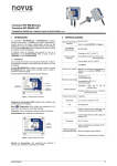
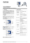
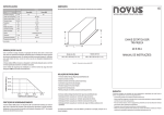
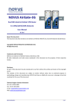
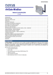
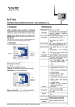
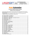
DigiRail-VA
INSTRUCTION MANUAL - V1.0x
MAIN FEATURES ............................................................................................................................................................... 2
SPECIFICATIONS .............................................................................................................................................................. 3
INSTALLATION AND OPERATION .................................................................................................................................... 4
MECHANICAL INSTALLATION..................................................................................................................................... 4
DIMENSIONS .......................................................................................................................................................... 4
ELECTRICAL INSTALLATIONS AND OPERATION ..................................................................................................... 4
INSTALLATION RECOMMENDATIONS ................................................................................................................. 5
POWER SUPPLY .................................................................................................................................................... 5
RS485 ...................................................................................................................................................................... 5
USB INTERFACE .................................................................................................................................................... 5
AC INPUTS .............................................................................................................................................................. 6
USING CURRENT TRANSFORMERS AND VOLTAGE TRANSFORMERS ..................................................... 7
MEASUREMENT OF FREQUENCY AND POWER FACTOR ........................................................................... 8
4-20 MA OUTPUT .................................................................................................................................................... 8
0-10 V OUTPUT....................................................................................................................................................... 9
INDICATOR LIGHTS (LEDS) ............................................................................................................................................ 10
USB DRIVER INSTALLATION .......................................................................................................................................... 11
WINDOWS 8 ............................................................................................................................................................... 11
DEFINITION AND SELECTION OF SERIAL PORT (COM) - WINDOWS......................................................................... 15
CONFIGURATION SOFTWARE ....................................................................................................................................... 16
EQUIPMENT SOFTWARE (FIRMWARE) UPDATE .................................................................................................... 16
MODBUS COMMANDS AND REGISTERS TABLE .......................................................................................................... 17
SUPPORTED MODBUS COMMANDS ....................................................................................................................... 17
READ HOLDING REGISTERS – 03H ................................................................................................................... 17
WRITE SINGLE REGISTER – 06H ....................................................................................................................... 17
WRITE MULTIPLE REGISTERS – 16H ................................................................................................................. 17
TABLE OF HOLDING REGISTERS ............................................................................................................................ 17
DETAILS ABOUT SOME REGISTERS ....................................................................................................................... 17
REGISTERS 20 TO 28 – MEASUREMENT VALUE IN INTEGER FORMAT ........................................................ 17
REGISTERS 200 AND 201 – SERIAL NUMBER................................................................................................... 18
REGISTER 202 – FIRMWARE VERSION ............................................................................................................. 18
FLOATING POINT FORMAT....................................................................................................................................... 18
WARRANTY...................................................................................................................................................................... 19
NOVUS AUTOMATION
1/19
DigiRail-VA
MAIN FEATURES
The DigiRail-VA is a transmitter and signal conditioner related to alternating current (single-phase), capable of
measuring the following quantities:
•
Voltage
•
Current
•
Active, reactive and apparent power
•
Frequency
•
Power Factor
The measured values can be read through its RS485/Modbus RTU interface, in addition to being transmitted
simultaneously using the 4-20 mA or 0-10 V outputs.
These features make the DigiRail-VA a great solution for measuring AC values in single-phase machines and facilities.
This product is not intended for commercial measurement of electrical energy!
NOVUS AUTOAMTION
2/19
DigiRail-VA
SPECIFICATIONS
Power Supply: 10 to 40 Vdc. Typical consumption: 50 mA @ 24 V.
Operation Temperature: 0 to 60 °C.
Dimensions: 99.5 x 114.0 x 17.5 mm
Weight: 96 g
Enclosure: PA66, with metallic attachment for 35 mm DIN track.
Internal protection against polarity inversion of the power supply voltage.
Wire gauge: AWG 28 to 12.
Recommended torque: 4 kgf·cm.
Voltage input range: 0 to 300 Vac (RMS).
Current input range: 0 to 5 Aac (RMS).
Frequency input range: between 45 to 65 Hz.
Analog outputs: 4-20 mA and 0-10 V.
Analog outputs retransmission zoom: 10:1. A bigger zoom is allowed, but with accuracy loss.
RS485 Serial Interface: Modbus RTU Protocol – 3 wires.
The inputs are isolated from the outputs and communication interfaces. Isolation: 2500 Vac / 1 minute.
Accuracy:
•
•
•
Reading by RS485
o
RMS voltage, RMS current, active power (real), apparent power and reactive power: 0.25%.
o
Power factor and frequency: 0.5 %.
Reading by the 4-20 mA output
o
RMS voltage, RMS current, active power (real), apparent power and reactive power: 0.5%.
o
Power factor and frequency: 1.0 %.
Reading by the 0-10 V output
o
RMS voltage, RMS current, active power (real), apparent power and reactive power: 0.5%.
o
Power factor and frequency: 1.0 %.
NOVUS AUTOAMTION
3/19
DigiRail-VA
INSTALLATION AND OPERATION
MECHANICAL INSTALLATION
The DigiRail-VA housing was designed for installation on DIN rail 35 mm.
For installation on the rail, you should locate the clamp at the base and press it against the track.
DIMENSIONS
Fig. 01 – Dimensions of the DigiRail-VA
ELECTRICAL INSTALLATIONS AND OPERATION
The DigiRail-VA has connectors for the power supply, for the inputs for AC measurement, for the output for analog
transmission and for the RS485 serial communication interface. Furthermore, it has a USB mini-B interface.
Fig. 02 - Connection terminals of DigiRail-VA.
Fig. 03 illustrates the electrical connection terminals. Terminals 4, 5 and 6 connect to the RS485/Modbus interface.
Terminals 7, 8 and 9 are intended for the analog outputs of the device (4-20 mA and 0-10 V – they share the same
"negative" terminal). Terminals 10, 11 and 12 are used to power the DigiRail-VA (terminals 10 and 11 are
interconnected internally).
Terminals 1, 2 and 3 are used for AC measurements and must be connected carefully. Refer to "AC Inputs" section for
connection details.
Fig. 03 – Electrical connections of the DigiRail-VA
NOVUS AUTOAMTION
4/19
DigiRail-VA
INSTALLATION RECOMMENDATIONS
We recommend using an appropriate fuse for the protection of the load to be measured.
• Input conductors should travel the system plant separately from the output and supply conductors, in grounded
electrical ducts.
• The power source of the instruments should come from a network that is appropriate for the instrumentation.
• The use of RC FILTERS (47 Ω and 100 nF, in series) parallel to the contactor coils and solenoids that are near or
connected to the equipment is recommended.
• In control applications, it is essential to consider what can happen when any part of the system fails.
• Section of used wires: minimum gauge of 0,14 mm².
POWER SUPPLY
The terminals 11 and 12 (or 10 and 12) are intended for the power supply for DigiRail-VA. The polarity of the power
supply must be carefully observed and the voltage level.
RS485
The RS485 interface of DigiRail-VA has terminals for 3-wire communication (including the common) and operates as a
Modbus RTU slave. The commands and the table of available registers can be viewed in the "Modbus Commands and
Register´s Table".
This interface can be configured to operate in the following baudrate: 1200, 2400, 4800, 9600, 19200, 38400, 57600 and
115200. In addition, it can be configured to operate with one or two stop bits, and parity even, odd or none.
More details on the implementation of a Modbus network via RS485 can be found in "Basic Concepts of RS485 and
RS422"; available on the CD that accompanies the product.
D1
D
D+
B
Two way data line.
Terminal 4
D0
D
D-
A
Inverted two way data line.
Terminal 5
Optional connection that improves the communication
performance.
Terminal 6
C
GND
USB INTERFACE
The DigiRail-VA has a USB device interface, used for configuration and monitoring. The Windows® operating system
will detect the device as a virtual serial port, allowing the use for supervisory software (SCADA).
To access this interface should be use the USB cable supplied with the equipment. When you first access, you need to
install the USB drivers on the computer. To see how to do this, see "Installing the USB Driver" section.
The communication of this interface is by the Modbus RTU protocol. The commands and the table of available registers
of this interface can be viewed in the "Modbus Commands and Register´s Table".
NOVUS AUTOAMTION
5/19
DigiRail-VA
AC INPUTS
The measurement circuit is electrically isolated from the rest of the equipment (power circuits and interfaces). However,
great care must be taken with electrical wiring connections (see section "Electrical Installation"). Take care to comply
with the maximum voltage and current set (see "Technical Specifications"). To measure higher voltages or current levels
to be measured, you should use current or voltage transformers (see section "Using current transformers and voltage
transformers").
The current measurement is done by an internal shunt resistor, so that the DigiRail-VA is connected in series with the
load to be measured. The following figure illustrates the device connected to the measuring circuit.
Fig. 04 – Measurement of voltage and current
Despite being common simultaneous measurement of voltage and current, you can connect just the part on the voltage
or current for measurement. In such cases, the measurement of the variable not connected will present value near zero
as the calculated values of the side variables (power and power factor). The figures below illustrate the connections in
these cases.
Fig. 05 – Solely measurement of voltage
NOVUS AUTOAMTION
6/19
DigiRail-VA
Fig. 06 – Solely measurement of current
USING CURRENT TRANSFORMERS AND VOLTAGE TRANSFORMERS
To expand the capacity of measuring levels of current or voltage DigiRail-VA, you can use voltage and/or current
transformers.
Fig. 07 – Connecting with current transformer
Fig. 08 – Connection with voltage transformer
In any of the cases, the maximum limits of the equipment must be respected, that is, the use of a current transformer
requires that it has a maximum output of 5 A and the use of a voltage transformer requires it to have an output maximum
of 300 V.
It is not recommended the use of simultaneous current and voltage transformers!
NOVUS AUTOAMTION
7/19
DigiRail-VA
The transformer ratio should be informed in DigiRail-VA settings so you can make the correction of the measured value,
adjusting to reality. Similarly, if the use of a transformer produces a phase shift between current and voltage in the
secondary, can be corrected through the option "Allow the Correction of Phase" in the "Diagnostics" tab for DigiConfig.
Example 1: Using a voltage transformer with 1000 V input and 300 V output.
In this case, you must inform on DigiConfig that be used a voltage transformer, selecting the appropriate box. You
must then inform the transformation ratio (in = 1000 V, out = 300 V).
Example 2: Using a current transformer with 50 A input and 4 A output.
In this case, you must inform on DigiConfig that be used a current transformer, selecting the appropriate box. You
must then inform the transformation ratio. As the input range is 0 to 5 A, and in this example the current transformer
to be used does not match the specification, adjust the parameter of the input current of the current transformer, so
that the ratio transformation is maintained.
50 / 4 = 12,5
12.5 x 5 = 62.5 → Input = 62,5 A
MEASUREMENT OF FREQUENCY AND POWER FACTOR
The frequency measurement is performed by the voltage input. In case the voltage value is close to zero, the frequency
calculation may be inaccurate and wrong values may happen. That is why the DigiRail-VA inhibits the frequency
measurement when voltage is near zero, typically below 0.5% of full scale. The inhibition of the frequency measurement,
indicated as "0 Hz", also happens when it is not performing the voltage measurement, as in the case shown in Fig 06.
Measurement of power factor there need voltage and current being measured by DigiRail-VA, it is a calculated value
based on the phase shift of these two quantities. If one of the values of the voltage or current is near zero, the calculated
value of power factor may result in wrong values. That is why the DigiRail-VA inhibits power factor measurement when
the voltage or current showing very small values, typically 0.1 % of full scale. This inhibition of measuring power factor,
denoted as "0", also happens when it is not performing the measurement of voltage or current, as in the cases illustrated
in Fig. 06 or 05.
4-20 mA OUTPUT
The 4-20 mA output can be used to transmit any of the measures in the AC input:
•
RMS Voltage
•
RMS Current
•
Active Power
•
Apparent Power
•
Reactive Power
•
Power Factor
•
Frequency
This output can be disabled if necessary.
Transmission is based on the full scale of the desired variable (e.g. 0 to 300 V for the rms voltage) or based on a
reduced scale (e.g. transmit a value of rms voltage on the range from 80 to 140 V, where 80 V corresponds to 4 mA and
140 V to 20 mA).
Finally, you can select the behavior of the 4-20 mA output in case of error: current lower than 4 mA or higher than 20 mA.
Fig. 09 – Connecting the 4-20 mA loop output.
NOVUS AUTOAMTION
8/19
DigiRail-VA
The 4-20 mA output is NOT isolated from the 0-10 V output, as they are interconnected
through the "negative" pole. In addition, this conductor is also connected to the negative of the
power source!
Therefore, care must be taken when using the outputs 4-20 mA and 0-10 V to send signals to
other devices that are powered by the same source than the DigiRail-VA.
If outputs 4-20 mA and 0-10 V are used simultaneously there may be problems if both are
read by another computer that has no they own isolated inputs.
0-10 V OUTPUT
The 0-10 V output can be used to transmit any of the measures in the AC input:
•
RMS Voltage
•
RMS Current
•
Active Power
•
Apparent Power
•
Reactive Power
•
Power Factor
•
Frequency
This output can be disabled if necessary.
The transmission is based on the full scale of the desired variable (e.g. 0-5 A for the rms current) or based on a reduced
scale (e.g. transmit a current effective value of range of 0.5 to 3 A, where 0.5 A corresponds to 0 V and 3 A corresponds
to 10 V).
Finally, you can select the behavior of the output 0-10 V on error: voltage equal to 0 V or exceeding 10 V.
Fig. 10 – Connecting the 0-10 V output
The 0-10 V output is NOT isolated from the 4-20 mA output, as they are interconnected
through the "negative" pole. In addition, this conductor is also connected to the negative of the
power source!
Therefore, care must be taken when using the outputs 4-20 mA and 0-10 V to send signals to
other devices that are powered by the same source than the DigiRail-VA.
If outputs 4-20 mA and 0-10 V are used simultaneously there may be problems if both are
read by another computer that has no they own isolated inputs.
NOVUS AUTOAMTION
9/19
DigiRail-VA
INDICATOR LIGHTS (LEDS)
Status LED:
It indicates the operational status of the equipment, according to the table shown below.
Led State
Meaning
ON steady
Measuring inputs OK
1 blink every 2 seconds
Voltage input value greater than the range operation
2 blinks every 2 seconds
Voltage input value lower than the range operation
3 blinks every 2 seconds
Current input value greater than the range operation
4 blinks every 2 seconds
Current input value lower than the range operation
5 blinks every 2 seconds
Input frequency out of operating range
OFF
Possible hardware malfunction
Communication LED:
It indicates the RS485/Modbus communication. Blinks when the DigiRail-VA is sending a Modbus frame via the RS485
interface (in response to a command).
NOVUS AUTOAMTION
10/19
DigiRail-VA
USB DRIVER INSTALLATION
In order to use the USB interface of the DigiRail-VA (so you can configure the equipment with the configuration
software, for example), it is necessary to install its USB driver. The installation steps can vary from computer to
computer, between different operating systems, and even between one version and another of the same operating
system.
Following are the steps and guidance screens for the driver installation.
WINDOWS 8
1. Connect the DigiRail-VA in a USB port on your computer. Windows will try to install a driver automatically and will
not succeed, because the necessary driver is not in its standard library.
2. On Desktop screen, right-click on the left-bottom corner of the screen and choose the "Control Panel" option. Then
choose the “System and Security” option, then the "System" option and, at last, "Device Manager".
3. Locate the DigiRail-VA (probably with an icon with an exclamation mark next to it) and double-click on it.
NOVUS AUTOAMTION
11/19
DigiRail-VA
4. Click on the button "Update Driver...".
5. Ask to "Browse my computer for driver software".
6. Enter the path of the folder where the drivers are located (the product CD or folder where you saved them when
downloaded from the site.)
NOVUS AUTOAMTION
12/19
DigiRail-VA
7. Wait for the installation to take start.
8. Windows will question this driver installation. Confirm selecting the option “Install”.
9. A message indicating successful installation will display.
NOVUS AUTOAMTION
13/19
DigiRail-VA
10. Returning to the Device Manager screen, you can check which virtual serial port is allocated to the DigiRail-VA.
NOVUS AUTOAMTION
14/19
DigiRail-VA
DEFINITION AND SELECTION OF SERIAL PORT (COM) - WINDOWS
The serial port associated with DigiRail-VA is automatically defined by the operating system a few moments after
connecting the DigiRail-VA. The user can easily identify or change the COM port associated with DigiRail-VA:
Control Panel / System / Hardware / Device Manager / COM & LPT Ports
Select the device "USB Serial Port" corresponding to the DigiRail-VA and click on "Properties". Select "Port Settings"
guide and click on "Advanced". In the "COM Port Number", select the serial port to be associated with DigiRail-VA.
Some serial ports can be checked while being used (In Use). Just select one of these ports if you know that it is not
being used by another peripheral device on your computer.
In some cases, the serial ports can be checked as in use even when the associated device is no longer installed on your
computer. In this case it is safe to associate this port to DigiRail-VA. The following figure presents the view of the device
manager containing a DigiRail-VA, and the screens showing the property screens where you can reset the associated
COM port.
NOVUS AUTOAMTION
15/19
DigiRail-VA
CONFIGURATION SOFTWARE
The software used for configuration of the DigiRail-VA is the DigiConfig (version 1.62 or higher). Besides the
configuration, it allows the verification of the input channel Reading and provides status information. This software is
supplied for free with the product CD and can also be downloaded at the manufacture’s website. Checking for updates
from time to time is recommended.
DigiConfig has a full help file with all of the necessary information for its complete usage, including the correct
configuration of the product configurations. To consult it, start the application and select the “Help” menu, or press the
“F1” key.
To begin configuring the DigiRail-VA, connect it to the computer (via USB or RS485) and select the "Communication"
option in the "Settings" menu. In the window that appears, select the correct serial port and configure the other
communication parameters. After applying the communication configuration, the system will be able to read the
configuration DigiRail-VA using the “Search” button located at the bottom left corner of the main window. To accelerate
the search, use the USB interface and use the option "Temporary". If you are using the RS485 interface and know the
equipment Modbus address, select only the "Starting Address" and enter the correct address. Once the equipment is
identified, it appears in the list on the left. Clicking on it will make the configuration data displayed on the right.
The configuration of the device is divided by functionality in several tabs. The choice of some options can affect the
limitation or absence of other configuration parameters. Last of all, the configuration should be applied to the equipment
using the Apply button.
The use of DigiRail-VA with full functionality is detailed in the chapter "Installation and Operation".
EQUIPMENT SOFTWARE (FIRMWARE) UPDATE
DigiRail-VA can update its internal software (firmware), allowing the benefits of new versions with new characteristics or
important improvements to be accessed without needing to send the equipment to technical assistance.
The latest update is available for download on the manufacturer website. The update process is done by DigiConfig,
using the related tab.
NOVUS AUTOAMTION
16/19
DigiRail-VA
MODBUS COMMANDS AND REGISTERS TABLE
The DigiRail-VA accepts some Modbus commands that are sent to its Modbus’ own address, operating as a network
slave. Commands forwarded to other slaves (routing) will be sent in a transparent way. The following listed Modbus RTU
commands (functions) are implemented, and these are interpreted by DigiRail-VA. For further information about each
command and the Modbus protocol in general, access the website www.modbus.org.
SUPPORTED MODBUS COMMANDS
READ HOLDING REGISTERS – 03H
This command can be used to read a value of one or up to the maximum consecutive holding registers, as shown in the
“Table of Holding Registers”.
WRITE SINGLE REGISTER – 06H
This command can be used to write on a holding register, as shown in the “Table of Holding Registers”.
WRITE MULTIPLE REGISTERS – 16H
This command can be used to write in multiple holding registers, as shown in the “Table of Holding Registers”.
TABLE OF HOLDING REGISTERS
The specified addresses correspond to the low level physical addresses, where zero (0) corresponds to the address PLC
40001. The Minimum and Maximum columns have a range of valid values for each parameter. The R/W column
indicates if the parameter is for reading and writing (R/W) or if it is only reading ® The Mnemonic SuperView states what
the register mnemonic is for in the SuperView software.
Address
Description
0
RMS Voltage (floating point – word high)
1
Voltage RMS (floating point – word low)
2
Current RMS (floating point – word high)
3
Current RMS (floating point – word low)
8
Active Power / real power (floating point – word high)
9
Active Power / real power (floating point – word low)
10
Apparent power (floating point – word high)
11
Apparent power (floating point – word low)
12
Reactive power (floating point – word high)
13
Reactive power (floating point – word low)
14
Power factor (floating point – word high)
15
Power factor (floating point – word low)
16
Frequency (floating point – word high)
17
Frequency (floating point – word low)
Minimum
Maximum
R/W
0.0
+3.4e+38
R
0.0
+3.4e+38
R
0.0
+3.4e+38
R
0.0
+3.4e+38
R
0.0
+3.4e+38
R
-1.0
Mnemonic
SuperView
R
0.0
+3.4e+38
R
20
Voltage RMS x 10 (integer 16 bits unsigned)
0
65535
R
21
Current RMS x 100 (integer 16 bits unsigned)
0
65535
R
CurrentRMS
22
Maximum peak voltage x 10 (integer 16 bits unsigned)
0
65535
R
MaxVoltagePeak
23
Maximum peak current x 100 (integer 16 bits unsigned)
0
65535
R
MaxCurrentPeak
24
Active Power (real power) x 10 (integer 16 bits
unsigned)
0
65535
R
ActivePower
25
Apparent power x 10 (integer 16 bits unsigned)
0
65535
R
ApparentPower
26
Reactive power x 10 (integer 16 bits unsigned)
0
65535
R
ReactivePower
27
Power factor x 1000 (integer 16 bits signed)
-1000
1000
R
PowerFactor
28
Frequency x 10 (integer 16 bits unsigned)
0
650
R
Frequency
31
Sign of the Reactive power (0 = inductive, 1 =
capacitive)
0
1
R
LeadLag
200
Serial number (word high)
0
65535
R
SerialNumber_H
201
Serial number (word low)
0
65535
R
SerialNumber_L
202
Firmware Version
0
999
R
FirmwareVersion
VoltageRMS
DETAILS ABOUT SOME REGISTERS
REGISTERS 20 TO 28 – MEASUREMENT VALUE IN INTEGER FORMAT
Reports the value of the respective variable input. The value will be multiplied by 10, 100 or 1000 depending on the
variable. Example: a value of 217.8 reads as 2178.
NOVUS AUTOAMTION
17/19
DigiRail-VA
REGISTERS 200 AND 201 – SERIAL NUMBER
They keep the serial number of the device. The two registers together form the serial number equipment, i.e., must be
treated as a 32-bit number.
REGISTER 202 – FIRMWARE VERSION
States the version of firmware of the device, as shown below:
If the version is “1.00” it will read the value as “100”. If the version is "2,04" it will read it as "204".
FLOATING POINT FORMAT
The DigiRail-VA uses floating point values of single precision (32 bits) according to the IEEE-754 standard (ANSI / IEEE
Standard for Binary Floating-Point Arithmetic).
NOVUS AUTOAMTION
18/19
DigiRail-VA
WARRANTY
Warranty conditions are available on our web site: www.novusautomation.com.
NOVUS AUTOAMTION
19/19