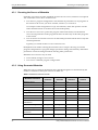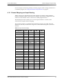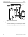
1
® Dolby DP570 Multichannel Audio Tool User’s Manual Issue 3 Part Number 91753 Dolby Laboratories, Inc. Corporate Headquarters Dolby Laboratories, Inc. 100 Potrero Avenue San Francisco, CA 94103‐4813 USA Telephone 415‐558‐0200 Fax 415‐863‐1373 www.dolby.com European Headquarters Dolby Laboratories, Inc. Wootton Bassett Wiltshire SN4 8QJ England Telephone (44) 1793‐842100 Fax (44) 1793‐842101 DISCLAIMER OF WARRANTIES: EQUIPMENT MANUFACTURED BY DOLBY LABORATORIES IS WARRANTED AGAINST DEFECTS IN MATERIALS AND WORKMANSHIP FOR A PERIOD OF ONE YEAR FROM THE DATE OF PURCHASE. THERE ARE NO OTHER EXPRESS OR IMPLIED WARRANTIES AND NO WARRANTY OF MERCHANTABILITY OR FITNESS FOR A PARTICULAR PURPOSE, OR OF NONINFRINGEMENT OF THIRD‐PARTY RIGHTS (INCLUDING, BUT NOT LIMITED TO, COPYRIGHT AND PATENT RIGHTS). LIMITATION OF LIABILITY: IT IS UNDERSTOOD AND AGREED THAT DOLBY LABORATORIES’ LIABILITY, WHETHER IN CONTRACT, IN TORT, UNDER ANY WARRANTY, IN NEGLIGENCE, OR OTHERWISE, SHALL NOT EXCEED THE COST OF REPAIR OR REPLACEMENT OF THE DEFECTIVE COMPONENTS OR ACCUSED INFRINGING DEVICES, AND UNDER NO CIRCUMSTANCES SHALL DOLBY LABORATORIES BE LIABLE FOR INCIDENTAL, SPECIAL, DIRECT, INDIRECT, OR CONSEQUENTIAL DAMAGES (INCLUDING, BUT NOT LIMITED TO, DAMAGE TO SOFTWARE OR RECORDED AUDIO OR VISUAL MATERIAL), COST OF DEFENSE, OR LOSS OF USE, REVENUE, OR PROFIT, EVEN IF DOLBY LABORATORIES OR ITS AGENTS HAVE BEEN ADVISED, ORALLY OR IN WRITING, OF THE POSSIBILITY OF SUCH DAMAGES. Dolby, Pro Logic, and the double‐D symbol are registered trademarks of Dolby Laboratories. Surround EX and Dialogue Intelligence are trademarks of Dolby Laboratories. All other trademarks remain the property of their respective owners. © 2006 Dolby Laboratories, Inc. All rights reserved. ii Part Number 91753 Issue 3 S06/13905/17674 Dolby® DP570 Multichannel Audio Tool User’s Manual Table of Contents List of Figures ......................................................................................................................................viii List of Tables ......................................................................................................................................... xi Chapter 1: Overview 1.1 Analog Monitoring Capabilities......................................................................................................... 1 1.2 Remote Control Capabilities ............................................................................................................ 1 1.3 Principles of Operation..................................................................................................................... 1 1.4 Main Applications ............................................................................................................................. 4 1.4.1 Use in DVD Mastering .............................................................................................................4 1.4.2 Use in Digital Television........................................................................................................... 4 Chapter 2: Getting Started 2.1 Unpacking and Inspection................................................................................................................ 5 2.2 Safety Information ............................................................................................................................ 5 2.3 Installing the DP570 ......................................................................................................................... 5 2.3.1 Venting..................................................................................................................................... 6 2.3.2 Making Input Connections .......................................................................................................6 2.3.3 Making Output Connections..................................................................................................... 6 2.3.4 Making the V Ref Connection .................................................................................................. 6 2.3.5 Making a Power Connection ....................................................................................................7 2.4 Installing the Remote Software ........................................................................................................ 7 2.4.1 System Requirements..............................................................................................................7 2.4.2 Installing the Software..............................................................................................................7 2.4.3 Hardware Connection ..............................................................................................................8 2.4.4 Configuring the Unit for Remote Operation.............................................................................. 8 2.4.5 Beginning and Ending Remote Operation ............................................................................... 8 2.4.6 Starting the Remote Software.................................................................................................. 9 2.4.7 Configure the Setup Monitor Tab.............................................................................................9 2.5 Selecting a Program Configuration ................................................................................................ 10 Chapter 3: Controlling the DP570 3.1 Using the Front-Panel Buttons ....................................................................................................... 13 3.1.1 Main and Shifted Functions of the Buttons ............................................................................ 14 3.1.2 Navigating the Front-Panel Menus ........................................................................................14 3.1.3 Selecting a Menu ................................................................................................................... 14 3.1.4 Other Shifted Functions ......................................................................................................... 15 3.2 Menu Structures............................................................................................................................. 15 3.3 Moving Between Menus................................................................................................................. 15 3.4 Monitoring Status Using the Front Panel ....................................................................................... 15 3.4.1 Reading the Default Status Display .......................................................................................15 3.4.2 Viewing Status Screens ......................................................................................................... 16 3.4.3 Reading the LED Indicators ................................................................................................... 16 Dolby® DP570 Multichannel Audio Tool User’s Manual iii 3.5 Using the Setup Menu.................................................................................................................... 18 3.5.1 Selecting Parameters............................................................................................................. 18 3.5.2 Entering Text.......................................................................................................................... 19 3.5.3 Exiting the Setup Menu.......................................................................................................... 19 3.5.4 Other Commands................................................................................................................... 19 3.5.5 Contrast Adjustment for the Front-Panel Display................................................................... 19 3.5.6 Analog Output Master Volume...............................................................................................20 3.6 Using the GPI/O Connector ...........................................................................................................20 3.6.1 Selecting GPI/O Functions.....................................................................................................20 3.6.2 Assigning GPI/O Functions to Specific Pins .......................................................................... 22 Chapter 4: Using the DP570 Features 4.1 Naming Programs .......................................................................................................................... 25 4.2 Adjusting the Monitor System ........................................................................................................25 4.3 Generating and Adjusting Metadata...............................................................................................25 4.3.1 Choosing the Source of Metadata ......................................................................................... 26 4.3.2 Using Generated Metadata.................................................................................................... 26 4.3.3 Using External Metadata........................................................................................................28 4.4 Troubleshooting Metadata Problems ............................................................................................. 29 4.5 Outputting Metadata....................................................................................................................... 29 4.6 Monitoring Downmixes................................................................................................................... 30 4.7 Measuring and Setting the Dialogue Level .................................................................................... 30 4.7.1 Identifying Normal or Average Level Program Segments...................................................... 30 4.7.2 Measuring the Average Loudness of Identified Clips............................................................. 31 4.8 Setting Dynamic Range Control.....................................................................................................34 4.9 Holding Metadata ........................................................................................................................... 34 4.10 User Presets ................................................................................................................................ 35 4.10.1 Authoring-Only Presets........................................................................................................35 4.10.2 Emulator-Only Presets......................................................................................................... 36 4.10.3 All Settings Presets.............................................................................................................. 36 4.10.4 Using Different Preset Types to Audition Settings ...............................................................36 4.11 Using Lt/Rt Input Mode ................................................................................................................ 36 4.12 Channel Mapping and Input Routing............................................................................................37 4.13 Using an External Shaft Encoder to Control Master Volume ....................................................... 38 4.14 Emulator Bypass .......................................................................................................................... 39 4.15 Solo Input Mode ........................................................................................................................... 39 4.16 Unity Gain Mode .......................................................................................................................... 39 4.17 Sticky Settings.............................................................................................................................. 40 4.18 Lt/Rt Gain Function ...................................................................................................................... 40 4.19 Dim Function ................................................................................................................................ 40 4.20 Master Trim and Master Volume..................................................................................................40 4.21 Dolby Pro Logic II Support ...........................................................................................................41 Chapter 5: Using the DP570 in DVD Mastering 5.1 Connecting the DP570 ................................................................................................................... 43 5.2 Typical Tasks .................................................................................................................................43 5.2.1 Setting the Dialogue Level .....................................................................................................44 5.2.2 Monitoring the Dialogue Level ...............................................................................................44 5.2.3 Monitoring Downmixes...........................................................................................................45 iv Dolby® DP570 Multichannel Audio Tool User’s Manual 5.3 Using the DP570 with Other Dolby Equipment ..............................................................................45 5.4 Most Important Metadata ...............................................................................................................45 Chapter 6: Using the DP570 in Live Remote Broadcast 6.1 Connecting the DP570 for Live Remote Broadcast ....................................................................... 47 6.2 Typical Tasks .................................................................................................................................48 6.2.1 Measuring and Setting Dialogue Level ..................................................................................49 6.2.2 Monitoring the Dialogue Level ...............................................................................................50 6.2.3 Monitoring Downmixes...........................................................................................................50 6.3 Using the DP570 with Other Dolby Equipment ..............................................................................50 6.4 Using Unity Gain Mode ..................................................................................................................50 6.5 Monitoring Metadata ...................................................................................................................... 50 6.6 Importance of Presets .................................................................................................................... 51 Chapter 7: Using the DP570 in Postproduction 7.1 Connecting the DP570 ................................................................................................................... 53 7.2 Typical Activities............................................................................................................................. 54 7.2.1 Measuring Dialogue Level .....................................................................................................54 7.2.2 Monitoring the Dialogue Level ...............................................................................................54 7.2.3 Monitoring Downmixes...........................................................................................................55 7.3 Using the DP570 with Other Dolby Equipment ..............................................................................55 7.4 Most Important Metadata ...............................................................................................................56 Chapter 8: Using the DP570 in Master Control 8.1 Connecting the DP570 ................................................................................................................... 57 8.2 Typical Activities............................................................................................................................. 58 8.2.1 Monitoring Downmixes...........................................................................................................58 8.2.2 Monitoring Dialogue Level .....................................................................................................59 8.3 Using Unity Gain Mode ..................................................................................................................60 8.4 Using the DP570 with Other Dolby Equipment ..............................................................................60 8.5 Most Important Metadata ...............................................................................................................60 Appendix A: Configuring a Monitor System A.1 Assigning Monitor System Configuration Settings......................................................................... 61 A.1.1 Opening the Monitor Setup Tab ............................................................................................61 A.1.2 Selecting Analog Outputs ...................................................................................................... 62 A.1.3 Choosing Bass Management Settings ..................................................................................62 A.1.4 Choosing Back Surround Speakers ...................................................................................... 64 A.1.5 Emulator Reversion ...............................................................................................................64 A.1.6 Setting the Lt/Rt Gain ............................................................................................................64 A.1.7 Configuring Dolby Pro Logic II...............................................................................................64 A.2 Setting Delay Values .....................................................................................................................65 A.2.1 Calculating Delay Values....................................................................................................... 66 A.2.2 Entering Delay Values ...........................................................................................................66 A.3 Calibrating Speaker Playback Levels ............................................................................................67 A.3.1 Setting the Digital Reference Level ....................................................................................... 67 A.3.2 Setting the Master Trim ......................................................................................................... 67 A.3.3 Setting the Master Volume .................................................................................................... 67 A.3.4 Picking a Target SPL............................................................................................................. 67 Dolby® DP570 Multichannel Audio Tool User’s Manual v A.3.5 Generating Test Noise...........................................................................................................68 A.3.6 Increasing the System Volume..............................................................................................68 A.3.7 Measuring SPL ...................................................................................................................... 69 A.3.8 Computing Channel Trims.....................................................................................................69 A.3.9 Subwoofer Calibration ...........................................................................................................69 A.3.10 Calibrating Emulator Output ................................................................................................ 70 A.4 Assigning a Dim Setting................................................................................................................. 70 Appendix B: Connector Specifications B.1 Front-Panel Remote Connector.....................................................................................................71 B.2 Digital Audio Inputs........................................................................................................................71 B.3 Digital Audio Outputs .....................................................................................................................71 B.4 Video Ref .......................................................................................................................................72 B.5 Lt/Rt Inputs ....................................................................................................................................72 B.6 Metadata Input Ports .....................................................................................................................72 B.7 Metadata Output Port .................................................................................................................... 72 B.8 Rear-Panel Remote Port ...............................................................................................................73 B.9 10Base-T Port (Ethernet)...............................................................................................................73 B.10 Multichannel Analog Output......................................................................................................... 73 B.11 Stereo/Mono/Solo Analog Output ................................................................................................ 74 B.12 GPI/O Connector .........................................................................................................................74 Appendix C: Front-Panel Menus C.1 Top-Level Setup Menu ..................................................................................................................75 C.2 Program Config ............................................................................................................................. 75 C.3 Metadata Params Submenu.......................................................................................................... 76 C.4 Measure Control Submenu............................................................................................................76 C.5 Monitor Control Submenu.............................................................................................................. 77 C.5.1 Dolby Pro Logic II Menu Submenu........................................................................................77 C.6 User Presets Submenu ................................................................................................................. 78 C.7 I/O Control Submenu.....................................................................................................................78 C.7.1 Router Config Submenu........................................................................................................79 C.7.2 GPI/O Setup Submenu.......................................................................................................... 79 C.8 Monitor Config Submenu...............................................................................................................80 C.8.1 Speaker Config Submenu .....................................................................................................80 C.8.2 Speaker Trims Submenu....................................................................................................... 81 C.9 Status Menu .................................................................................................................................. 82 Appendix D: A Guide to Dolby Metadata D.1 Metadata Overview........................................................................................................................83 D.2 Dialogue Level...............................................................................................................................86 D.3 Dynamic Range Control ................................................................................................................ 88 D.4 Dynamic Range Control Profiles ................................................................................................... 89 D.5 Downmixing ................................................................................................................................... 90 D.6 Parameter Definitions .................................................................................................................... 92 D.6.1 Universal Parameters............................................................................................................93 D.7 Extended Bitstream Information Parameters............................................................................... 101 D.7.1 Preferred Stereo Downmix Mode ....................................................................................... 101 D.7.2 Lt/Rt Center Downmix Level ............................................................................................... 102 vi Dolby® DP570 Multichannel Audio Tool User’s Manual D.7.3 Lt/Rt Surround Downmix Level............................................................................................102 D.7.4 Lo/Ro Center Downmix Level.............................................................................................. 102 D.7.5 Lo/Ro Surround Downmix Level..........................................................................................103 D.7.6 Surround EX Mode.............................................................................................................. 103 D.7.7 A/D Converter Type.............................................................................................................104 D.8 Metadata Combinations............................................................................................................... 104 Appendix E: Regulatory Notices and Fuse Information E.1 Regulatory Notices ......................................................................................................................107 E.1.1 USA .....................................................................................................................................107 E.1.2 Canada ................................................................................................................................108 E.1.3 UK........................................................................................................................................ 108 E.1.4 EU........................................................................................................................................ 108 E.2 Product End-of-Life Information...................................................................................................111 E.3 Fuse Information..........................................................................................................................111 E.3.1 Main Fuse............................................................................................................................ 112 E.3.2 Internal Fuse........................................................................................................................ 112 Index ......................................................................................................................................................113 Dolby® DP570 Multichannel Audio Tool User’s Manual vii List of Figures Figure 1-1 Figure 2-1 Figure 2-2 Figure 3-1 Figure 3-2 Figure 3-3 Figure 3-4 Figure 3-5 Figure 3-6 Figure 3-7 Figure 4-1 Figure 4-2 Figure 4-3 Figure 4-4 Figure 4-5 Figure 4-6 Figure 4-7 Figure 4-8 Figure 4-9 Figure 4-10 DP570 Functional Block Diagram.......................................................................................... 3 Monitor Configuration Tab ................................................................................................... 10 Program Configuration Selector .......................................................................................... 11 DP570 Control Options........................................................................................................ 13 Front-Panel Buttons............................................................................................................. 14 Default Status Menu Screen................................................................................................ 16 Basic LED Indicators ........................................................................................................... 17 Channel Activity LED Indicators .......................................................................................... 18 Initial Setup Menu Screen ................................................................................................... 18 GPI/O Pin Numbers............................................................................................................. 22 Metadata Tabs..................................................................................................................... 27 Adding a Second Program .................................................................................................. 29 Downmix Options ................................................................................................................ 30 Measurement Control Options............................................................................................. 30 Short-term Measurements .................................................................................................. 32 Metadata Hold Button.......................................................................................................... 34 User Preset Window............................................................................................................ 35 Unity Gain Mode Box........................................................................................................... 39 Lt/Rt Gain Control................................................................................................................ 40 Master Trim Control41 Figure 4-11 Figure 5-1 Figure 5-2 Figure 5-3 Figure 6-1 Figure 6-2 Figure 6-3 Figure 7-1 Figure 7-2 Figure 7-3 Figure 8-1 Figure 8-2 Figure 8-3 Figure A-1 Figure A-2 Figure A-3 Figure A-4 Figure A-5 Figure A-6 Figure A-7 Figure A-8 Figure A-9 Figure A-10 Figure C-1 Figure C-2 Figure C-3 Master Volume Control41 Content Creation ................................................................................................................. 43 Dialogue Level Controls ...................................................................................................... 44 Downmix Monitoring Controls.............................................................................................. 45 Typical Live Remote Transmission Setup ........................................................................... 48 Typical Downmix Parameters.............................................................................................. 49 Dialogue Level Controls ...................................................................................................... 49 Typical Postproduction Setup.............................................................................................. 53 Dialogue Level Controls ...................................................................................................... 54 Typical Options for Monitoring Downmixes ......................................................................... 55 Typical Master Control Setup .............................................................................................. 58 Typical Downmix Options .................................................................................................... 59 Dialogue Level Controls ...................................................................................................... 59 Setup Button........................................................................................................................ 61 Monitor Setup Tab ............................................................................................................... 62 Bass Management Settings................................................................................................. 64 Lt/Rt Gain Function.............................................................................................................. 64 Pro Logic II Controls ............................................................................................................ 65 Speaker Delay Values ......................................................................................................... 66 Digital Reference Level ....................................................................................................... 67 Multichannel Trims Controls ................................................................................................ 69 Real-time Analyzer (RTA) Display....................................................................................... 70 Dim Button........................................................................................................................... 70 Top-Level Setup Menu ........................................................................................................ 75 Metadata Parameters Submenu.......................................................................................... 76 Measure Control Submenu.................................................................................................. 76 Dolby® DP570 Multichannel Audio Tool User’s Manual viii List of Figures Figure C-4 Figure C-5 Figure C-6 Figure C-7 Figure C-8 Figure C-9 Figure C-10 Figure C-11 Figure C-12 Figure C-13 Figure D-1 Figure D-2 Figure E-1 Monitor Control Submenu.................................................................................................... 77 Pro Logic II Submenu .......................................................................................................... 77 User Presets Submenu ....................................................................................................... 78 I/O Control Submenu........................................................................................................... 78 Router Config Submenu ...................................................................................................... 79 GPI/O Setup Submenu........................................................................................................ 79 Monitor Config Menu ........................................................................................................... 80 Speaker Config Submenu ................................................................................................... 80 Speaker Trims Submenu..................................................................................................... 81 Status Menu ........................................................................................................................ 82 Metadata Flow from Production to Consumer ..................................................................... 84 DRC Profile.......................................................................................................................... 89 Fuse Replacement ............................................................................................................ 112 Dolby® DP570 Multichannel Audio Tool User’s Manual ix List of Figures x Dolby® DP570 Multichannel Audio Tool User’s Manual List of Tables Table 3-1 Table 3-2 Table 3-3 Table 3-4 Table 3-5 Table 3-6 Table 3-7 Table 3-8 Table 4-1 Table 4-2 Table 4-3 Table 4-4 Table 4-5 Table 4-6 Table A-1 Table B-1 Table B-2 Table B-3 Table B-4 Table B-5 Table B-6 Table D-1 Table D-2 Table D-3 Table D-4 Table D-5 Table D-6 Table D-7 Table D-8 Table D-9 Table D-10 Table D-11 Table D-12 Table D-13 Table D-14 Table D-15 Table D-16 Table D-17 Table D-18 Table D-19 Table D-20 Table D-21 Table D-22 Table D-23 Table D-24 Table D-25 Table D-26 Table D-27 Front-Panel Navigation Buttons ...............................................................................................14 Shifted Key Functions .............................................................................................................. 15 Basic Status Indications ...........................................................................................................17 Channel Activity LED Indications ............................................................................................. 18 Text Entry Commands.............................................................................................................. 19 GPO Functions Available ......................................................................................................... 20 GPI Functions Available ...........................................................................................................21 GPI/O Pins Available................................................................................................................ 22 Metadata Parameter Defaults ..................................................................................................26 Measurement Mode Applications ............................................................................................. 33 Input Channel Routings............................................................................................................37 Default Router Presets ............................................................................................................. 38 Shaft Decoder Signal Descriptions...........................................................................................38 Shaft Decoder Signal Electrical Characteristics ....................................................................... 39 Bass Management Options ...................................................................................................... 63 Front-Panel Remote Connector Pinout .................................................................................... 71 Metadata Input Port Pinout....................................................................................................... 72 Metadata Output Port Pinout....................................................................................................72 Rear-Panel Remote Port Pinout ...............................................................................................73 Multichannel Analog Output Pinout .......................................................................................... 73 Stereo/Mono/Solo Analog Output Pinout ................................................................................. 74 Profession and Consumer Metadata Types ............................................................................. 85 ................................................................................ Outputs from Different Equipment Types91 Program Configuration Settings ...............................................................................................93 Channel Mode Definition and Data Rates ................................................................................ 94 LFE Channel Settings .............................................................................................................. 95 itstream Mode Options ............................................................................................................. 95 RF Overmodulation Protection Setting .....................................................................................96 Center Downmix Level Settings and Definitions ...................................................................... 97 Surround Downmix Level Settings and Definitions ..................................................................97 Dolby Surround Mode Settings and Definitions........................................................................97 Audio Production Information Settings and Definitions ............................................................ 98 Mixing Level Setting ................................................................................................................. 98 Room Type Setting................................................................................................................... 98 Copyright Bit Settings ...............................................................................................................99 Original Bitstream Settings....................................................................................................... 99 DC Filter Settings .....................................................................................................................99 Lowpass Filter Setting ............................................................................................................ 100 LFE Lowpass Filters............................................................................................................... 100 Surround 3 dB Attenuation Settings ....................................................................................... 100 Surround Phase Shift Setting ................................................................................................. 101 Preferred Stereo Downmix Mode Setting ............................................................................... 101 Lt/Rt Center Downmix Level Setting ......................................................................................102 Lt/Rt Surround Downmix Level Setting .................................................................................. 102 Lo/Ro Center Downmix Level Setting .................................................................................... 102 Lo/Ro Surround Downmix Level Settings............................................................................... 103 Surround EX Mode................................................................................................................. 103 A/D Converter Type Setting ...................................................................................................104 Dolby® DP570 Multichannel Audio Tool User’s Manual xi List of Tables Table D-28 Metadata Combinations .........................................................................................................104 xii Dolby® DP570 Multichannel Audio Tool User’s Manual Chapter 1 Overview The Dolby® DP570 provides unprecedented control and reference monitoring for the creation and delivery of Dolby Digital and Dolby E surround sound as well as metadata for DTV and DVDs. The DP570 Multichannel Audio Tool simplifies the preparation of content for Dolby E and Dolby Digital encoding. Its ability to control and configure the monitoring environment and its ability to set and edit metadata parameters makes it a key tool for postproduction, DVD, and digital television facilities. You can monitor exactly what the consumer ultimately hears in real time, without the need to decode and reencode material. The convenient interface lets you take full advantage of the audio metadata that Dolby Digital bitstreams deliver to consumer decoders, ensuring that home listeners hear programs exactly as originally intended. The DP570 enables the user to create new metadata, and to modify any previously generated metadata. Its built‐in Leq(A) meter provides the crucial ability to determine and set the dialogue normalization (dialnorm) value. The DP570 outputs metadata as a separate data stream, to be combined later with the multichannel audio in a Dolby E or Dolby Digital encoder. 1.1 Analog Monitoring Capabilities The DP570 is particularly useful in conjunction with audio consoles lacking adequate multichannel monitoring facilities. With the addition of the high‐performance 24‐bit Cat. No. 548 Analog Option Card, independent 5.1‐channel, two‐channel, and mono outputs are available to feed three separate speaker systems. The card also gives users control over levels, channel mutes, and channel solos through a master volume control, speaker trim controls, and an input for a console solo bus. An additional input and integrated Dolby Pro Logic® II and Pro Logic decoders allow proper monitoring of Lt/Rt sources and downmixes from all other inputs. 1.2 Remote Control Capabilities The DP570 contains extensive GPI/O control and includes a software remote application for use with a Windows®‐based PC. The optional Cat. No. 549 GPI/O Controller provides key remote control functions. 1.3 Principles of Operation Until the DP570, the only way to hear the effect of metadata on audio during mastering was to pass the audio through the Dolby Digital encode/decode chain. This procedure could not be achieved in real time and offered an unwieldy interface. The DP570 provides this function in real time by applying metadata parameters to baseband PCM audio. This emulation function allows you to preview the effects of downmixing, setting dialogue Dolby® DP570 Multichannel Audio Tool User’s Manual 1 Overview Principles of Operation level, Pro Logic decoding, and the other functions controlled by metadata and experienced by consumers. The DP570’s convenient and user‐friendly interface simplifies multichannel audio production and mastering. Figure 1‐1 shows the audio path of the DP570 broken into major functional blocks. Features that control the operation of a block are connected to it by a dotted line. Digital audio input on the DP570 is via four female BNC connectors, allowing a total of eight channels. The emulator section of the DP570, like the DP571, requires the input channel assignment to conform to a fixed SMPTE 320M definition based upon the program configuration selected. Since previously recorded material may arrive in formats that do not match the chosen program configuration, the DP570 provides the ability to reroute the input channels to match the expected configuration, allowing other equipment to be sent the correct channel assignment. The emulator section provides the bulk of the audio processing, including application of metadata, downmixing, and Pro Logic decoding. All possible listening options allowed by consumer decoders are provided in the emulator (from high‐end home theaters to mono TV sets). Note that the inputs to the emulator section may be multiple, unrelated channels but the outputs are referred to as speaker channels and represent only the active program (the program currently being worked on or monitored). Once the input channel configuration has been set, the selected active program appears in the appropriate speaker channels irrespective of the programʹs appearance on the input channels, thereby simplifying installation and integration into existing multichannel monitoring environments. The emulator section is followed by the bass management section, which provides the ability to route low frequencies to the appropriate speaker channels. The output of the bass management section is sent to the digital audio (emulator) outputs as well as the analog monitor section (if fitted). 2 Dolby® DP570 Multichannel Audio Tool User’s Manual Emulator Config Spkr select List Mode Metadata Prgm Select Principles of Operation Router Config Overview Output Meter Measurement Point Input Meter Measurement Point L R 1/2 L/R C Emulator 3/4 AES Rcvr x4 Router (DRC, dialnorm, downmix, P/L decode) SW Bass management AES Xmit x4 Ls Rs 5/6 C/ SW Ls/ Rs Bsl Bsl / Bsr Bsr Spkr Trim Vol, Mute 7/8 L 1/2 R 3/4 AES Xmit x4 From router outputs C D/A x8 5/6 Trims x8 Volume Output Bal. x8 SW Ls Rs 7/8 Bsl Bsr Lt/ Rt AES Rcvr Solo Mode Router Spkr Select Output Bal. (2) Lo Ro L R Output Bal. Mono Cat. No. 548 Analog Option Card Figure 1-1 DP570 Functional Block Diagram Dolby® DP570 Multichannel Audio Tool User’s Manual 3 Overview Main Applications The Cat. No. 548 Analog Option Card provides an analog monitor section and some additional features to ease interfacing to existing mixing and monitoring environments. This optional analog monitor section provides features including multiple speaker‐configuration outputs, a master volume control, speaker trim controls, and an input for a console solo bus. 1.4 Main Applications The DP570 can be successfully deployed wherever there is a need to monitor the quality of digital audio, and to review existing metadata. It is currently most common in two applications: • DVD mastering • Creation and broadcast of DTV content 1.4.1 Use in DVD Mastering A DVD author is typically preparing mixed audio for writing to the DVD: generating metadata, verifying levels, and auditioning downmixes. This process is described in detail in Using the DP570 in DVD Mastering on page 43. 1.4.2 Use in Digital Television Here’s an example of the process flow in DTV: In a broadcast truck parked outside a football stadium, the program mixer chooses the appropriate metadata for the audio program being created. The resulting audio program, together with metadata, is encoded as Dolby E data and sent to the television station via fiber, microwave, or other transmission link. This process is discussed in detail in Using the DP570 in Live Remote Broadcast on page 47. At the receiving end of this transmission, the Dolby E stream is decoded back to baseband audio and metadata. The audio program and the metadata are monitored, altered, or re‐created as other elements of the program are added in preparation for broadcast. This process is discussed in detail in Using the DP570 in Postproduction on page 53. This new audio program/metadata pair, reencoded as Dolby E data, leaves the postproduction studio and passes through the television station to Master Control, where many incoming Dolby E streams are once again decoded back to their individual baseband digital audio/metadata programs. The audio program/metadata pair that is selected to air is sent to the transmission Dolby Digital encoder, which encodes the incoming audio program according to the metadata stream associated with it, thereby simplifying the transmission process. This process is discussed in detail in Using the DP570 in Master Control on page 57. Finally, the Dolby Digital signal is decoded in the consumer’s home, with metadata providing the information for that decoding process. Through the use of metadata, the mixer in the truck has been able to control the home decoder for the sporting event, while segments such as news breaks, commercials, and station IDs are similarly decoded, each using its own metadata. 4 Dolby® DP570 Multichannel Audio Tool User’s Manual Chapter 2 Getting Started This chapter describes the actions necessary to begin using the DP570 in a basic configuration. 2.1 Unpacking and Inspection Before unpacking the unit, inspect the outer carton for shipping damage. If the carton shows damage, inspect the unit in those areas. Several essential items are provided with the unit, including: • Power cords for use in the United States and continental Europe. • A CD‐R containing the DolbyRemote 570 application and soft copy documentation. • A bag containing 75Ω terminators, rackmount screws and washers, and a serial connection cable for the front‐panel RS‐232 port. • Safety notices. • Warranty information. Fill out the warranty card and return it to Dolby Laboratories. Note: To maintain your eligibility for software upgrades, register your product on the software upgrades page at www.dolbysupport.com. 2.2 Safety Information Before you begin installing your DP570, refer to the important safety notices and fusing information included in Regulatory Notices and Fuse Information on page 107. 2.3 Installing the DP570 Operating a DP570 requires: • A rackspace two standard units high • Venting • Input connections • Output connections • A suitable monitoring system (For information on setting up and calibrating a successful monitoring system, see Configuring a Monitor System on page 61.) • A power connection Dolby® DP570 Multichannel Audio Tool User’s Manual 5 Getting Started Installing the DP570 2.3.1 Venting Dolby® professional audio products are designed to operate within a temperature range of 5°C to 45°C. They use natural convection cooling and therefore should not be mounted directly above any heat‐generating equipment. The DP570 has vent holes in the front and back of the unit, and can be placed directly above or below other rack‐mounted gear. 2.3.2 Making Input Connections Connect the mandatory multichannel PCM signals to the digital jacks. Use care to attach the input cables to the proper connector to avoid inadvertently moving channels. For a discussion of the connector types used on the DP570, see Connector Specifications on page 71. Note: The DP570 will not operate without a valid sample clock signal present at the channel 1/2 input connection. You may also connect a Dolby Surround encoded stereo PCM mix to either of the Lt/Rt Inputs jacks. Use the second jack either to pass the signal to another device or to terminate the connection with a 75Ω impedance. 2.3.3 Making Output Connections There are two sets of digital audio outputs on the rear panel. One is the output from the router and the other is from the emulator. For a discussion of the connector types used on the DP570, see Connector Specifications on page 71. Router Output Use the Router Outputs for the main digital signal output regardless of whether you are reassigning signals to different channels. For information on how to reassign input signals to different channels, see Channel Mapping and Input Routing on page 37. Emulator Output These outputs are affected by metadata changes you make in the DP570 and should only be used to send a signal to the monitoring system. Connect them to your own D/A converter if you are monitoring without using the Cat. No. 548 Analog Option Card. 2.3.4 Making the V Ref Connection Connect the V Ref signal to either of the two jacks on the rear panel. Use the second jack either to pass the signal to the next device in the chain, or to terminate it with a 75Ω impedance on the last device in the signal chain. 6 Dolby® DP570 Multichannel Audio Tool User’s Manual Getting Started Installing the Remote Software If there is no video input or the video input fails, the DP570 generates a default frame based on 1,536 samples at the current audio clock rate, to match Dolby Digital frame rates. For a discussion of the connector types used for the V Ref connection on the DP570, see Connector Specifications on page 71. 2.3.5 Making a Power Connection The DP570 contains a 90–264 VAC, 50–60 Hz, auto‐sensing power supply, 40W maximum; designed to operate from a centrally switched power source. The power cord supplied with the unit is six feet long. 2.4 Installing the Remote Software Once power is applied the DP570 will display the main status screen. We strongly recommend that you continue on to install the remote management software. DolbyRemote 570 provides quick access to the DP570ʹs functions including some that are not available from the DP570 front‐panel interface. Use of DolbyRemote 570 allows the DP570 to be located in another room or at a distance from the operator. While DolbyRemote 570 is in operation, the Remote LED on the front panel of the DP570 is lit and access to the setup menu via the front‐panel buttons is disabled. Note: The RS‐232 specification limits serial cable length to 50 feet. Using low capacitance cables can, however, extend this limit up to 147 feet. Refer to the specification for exact information. 2.4.1 System Requirements DolbyRemote 570 can be run on a PC that meets these minimum requirements: • 166 MHz Pentium processor • 32 MB RAM • 10 MB available hard drive storage • Super VGA video card with at least 800 × 600 resolution 2.4.2 Installing the Software DolbyRemote 570 software is provided as DP570.ZIP on the CD packed in the shipping carton. Simply extract the ZIP file to a folder on the local machine, and then click the executable to begin using the application. Dolby® DP570 Multichannel Audio Tool User’s Manual 7 Getting Started Installing the Remote Software 2.4.3 Hardware Connection To connect the DP570 to its remote control device, use a serial cable from your computer to either the front‐panel Remote RS-232 port or the rear‐panel Remote RS-485 port. For connector and pin descriptions, see the Front‐Panel Remote Connector on page 71 and the Rear‐Panel Remote Port on page 73. Note: You can use a USB‐to‐serial adapter to connect the serial cable to a laptop. However, these adapters occasionally cause enough delay to interfere with data communications. This problem is mostly likely to occur during firmware upgrades. Take care to establish the best possible connection before beginning an upgrade. 2.4.4 Configuring the Unit for Remote Operation A DP570 arrives preconfigured to communicate with the remote application at 115,200 baud, using a unit address 8280. The remote response from the unit is fastest at 115,200 baud, so we recommend using that rate if possible. The unit does support slower communication rates. The unit address is only important when more than one DP570 is attached to the same COM port. Contact Technical Support if you need assistance with unit addressing in that situation. You can change the default remote operation settings from the unit front panel on the System Settings portion of the Setup menu. Follow these steps. 1. At the main status screen, shown in the Default Status Menu Screen on page 16, press the Setup button. 2. At the main Setup menu press Settings (seven times). until the LCD second line reads System 3. Press Enter. 4. Press . The second line reads Baud Rate. Press Enter if you need to change it. Then press until the baud rate you wish to use appears in the display. Then press Esc to return to the main system settings menu. 5. Press twice. The second line reads Unit Address. Press Enter if you need to change it. 6. Enter a new unit address using the procedures for text entry explained in detail in Entering Text on page 19. 2.4.5 Beginning and Ending Remote Operation To begin remote operation, on the front panel press and release Shift once so that the button lights up, then press . While in Remote mode, the front‐panel LED labeled Remote glows green, and setup commands cannot be made from the unit front panel. The status menus, discussed in Monitoring Status Using the Front Panel on page 15, continue to display accurate unit status in Remote mode. 8 Dolby® DP570 Multichannel Audio Tool User’s Manual Getting Started Installing the Remote Software To end remote operation and resume using the front‐panel interface, press Shift then again. 2.4.6 Starting the Remote Software To start the remote software: 1. Double‐click the program icon. 2. Review the communication settings, and modify them if necessary. 3. Click OK. The DP570 alerts you that it is opening the device and, when communication is established, displays the main application screen shown in Figure 4‐1. 2.4.7 Configure the Setup Monitor Tab Before the DP570 can begin service you must configure it to reflect your monitoring system. 1. Click Setup on the application button bar. The system opens the Monitor tab shown in Figure 2‐1. 2. Check the appropriate settings. For a detailed discussion of the concepts and procedures for setting up a monitoring system, see Configuring a Monitor System on page 61. Your DP570 is now ready to use. Dolby® DP570 Multichannel Audio Tool User’s Manual 9 Getting Started Selecting a Program Configuration Figure 2-1 2.5 Monitor Configuration Tab Selecting a Program Configuration The first step in monitoring is to select a program configuration that reflects the number of channels within the program(s) you will monitor. The DP570 supports 22 program configurations shown in Program Configuration Settings on page 93. The number of channels in the selected program configuration affects the default metadata applied by the DP570. Tip: Take care to select the program configuration that matches your input exactly. To set the Program Configuration, choose the appropriate one from the drop‐down list shown in Figure 2‐2. This area is also where you choose a source for the program configuration: Int, meaning internal, the DP570 detects it; or Ext1, or Ext2, meaning it is derived from one or the other of the external metadata inputs. 10 Dolby® DP570 Multichannel Audio Tool User’s Manual Getting Started Selecting a Program Configuration Figure 2-2 Program Configuration Selector Dolby® DP570 Multichannel Audio Tool User’s Manual 11 Getting Started 12 Selecting a Program Configuration Dolby® DP570 Multichannel Audio Tool User’s Manual Chapter 3 Controlling the DP570 As shown in Figure 3‐1, you can control the DP570 in three ways: • Directly, by pushing buttons on the front panel of the unit • Remotely, using the DolbyRemote 570 software over a serial connection to a PC • Remotely, using a hardware remote panel connected to the unit GPI/O connector Note: Direct control and remote control using DolbyRemote 570 are mutually exclusive. You cannot use both the front panel and the remote application at the same time. However, you can use GPI/O simultaneously with the either the remote application or direct control. GPI/O Interface (Cat. No. 549) DP570 Laptop PC + Remote SW GPI/O V Ref Remote MD 1 In 2 MD Out PCM Inputs Figure 3-1 1/2 3/4 5/6 DP571 or DP569 DP570 Control Options Most users will control their units with the remote software, and most of this manual focuses on this approach. This chapter gives summary instructions for controlling the unit from the unit front panel and via the GPI/O connector. 3.1 Using the Front-Panel Buttons The eight buttons shown in Figure 3‐2 let you navigate the menus and select functional parameters. Dolby® DP570 Multichannel Audio Tool User’s Manual 13 Controlling the DP570 Using the Front-Panel Buttons Remote Delete Insert Status Contrast Volume Bypass Figure 3-2 Front-Panel Buttons 3.1.1 Main and Shifted Functions of the Buttons Most of the buttons have two functions: a main function and a shifted function. The main function, indicated on the button itself, is active when the Shift button is not lit. The shifted function is active when the Shift button is pressed and lit. This function is indicated on the panel above or below the button as shown in Figure 3‐2. 3.1.2 Navigating the Front-Panel Menus To navigate the menus, use the main function of the buttons described inTable 3‐1. Table 3-1 Front-Panel Navigation Buttons Legend or or Action Displays the previous menu item available on line 2 of the display. Displays the next menu item available on line 2 of the display. Esc Displays the next higher menu level. If you have changed the display from the current parameter value without pressing Enter, returns display to current parameter value. Enter Accepts the item on line 2 of the display and changes function status and menu display accordingly. 3.1.3 Selecting a Menu The main function of the Setup key moves you from the default status menu to the Setup menu, when Remote mode is not activated. In Remote mode, the Setup menu is unavailable from the front panel. When the Shift button is pressed and lit, the Setup button returns you from the Setup menu to the status menu. 14 Dolby® DP570 Multichannel Audio Tool User’s Manual Controlling the DP570 Menu Structures 3.1.4 Other Shifted Functions When the Shift button is pressed and lit, the other keys have the functions listed in Table 3‐2. Table 3-2 Shifted Key Functions Shift + Key Action Puts the unit in remote mode. Deletes the current character from text fields. Opens the contrast control for the DP570 display, letting you increase or decrease the contrast. Inserts a character at the cursor in text fields. 3.2 Enter Opens the main volume control for the optional analog outputs. Esc Engages Bypass mode, discussed in Emulator Bypass on page 39, skipping most processing. Menu Structures The DP570 front panel displays one or the other of two separate menu structures: • The panels of the status menu, which display the current status of the unitbut do not allow changes • The Setup menu, which allows you to change the way the unit operates Tip: When you operate the DP570 using the front panel, take care to note whether you are using the Setup or status menu and memorize the methods of moving from one to the other. 3.3 Moving Between Menus Moving between the two menus is simple. To move from the status menu to the Setup menu, press the Setup button. To move from the Setup menu back to the status menu, press Shift then Setup. 3.4 Monitoring Status Using the Front Panel The front‐panel status menus give you comprehensive information about the current state of the unit. 3.4.1 Reading the Default Status Display The default display when the unit powers up is the top screen of the status menu shown in Figure 3‐3. Dolby® DP570 Multichannel Audio Tool User’s Manual 15 Controlling the DP570 Monitoring Status Using the Front Panel 1 2 5.1 + 2 Internal 5 4 3 Prog 1 3/2L 27 Figure 3-3 Default Status Menu Screen The main status display includes five elements: 1. Program configuration: can contain any of the supported program configurations listed in Program Configuration Settings on page 93. The example in Figure 3‐3 includes two programs: a 5.1 mix and a two‐channel mix. Metadata for the programs is controlled separately. 2. Metadata source in use. The options are: Internal, Ext 1, or Ext 2. 3. Program name: text, which can be user‐entered, describing the program that is selected for emulation and metadata authoring. Naming Programs on page 25 explains the value of this feature. 4. Channel mode: Displays the current program selection, in this example a 5.1 mix. Here 3/2 is the Channel mode (three front channels, two rear channels). The L indicates that the LFE channel is also enabled. 5. Dialogue level: Displays the dialogue level value for the currently selected program. In this example, –27 is the selected value for the dialogue level parameter. See Measuring and Setting the Dialogue Level on page 30 for more information. 3.4.2 Viewing Status Screens Press the up or down arrow from the main status screen to view the additional screens that provide details of the following current states: • Master volume • Current values of individual metadata parameters • Video reference • Audio input • User preset • Errors • Firmware version number Tip: The metadata parameter and error displays are multiscreen displays. Use the Enter and Esc keys as described in Table 3‐1 to move around in them. 3.4.3 Reading the LED Indicators The LED indicators at the top of the front panel provide information about the signal input and output. 16 Dolby® DP570 Multichannel Audio Tool User’s Manual Controlling the DP570 Monitoring Status Using the Front Panel Basic Status Indicators The indicators shown in Figure 3‐4 display the basic status information listed in Table 3‐4. Delay Lt/Rt Input Metadata Input Solo 1 Figure 3-4 Remote V Ref Fault Error 2 Basic LED Indicators Table 3-3 Basic Status Indications LED Indication and Meaning Delay This LED is not active in this version. Lt/Rt Input Green: Lt/Rt Input mode is active. Off: Inactive Solo Green: Solo input function is active. Off: Inactive. Metadata Input There are separate indicators for inputs 1 and 2. Green: Signal is locked and valid. Red: Invalid signal while unit is in External Metadata mode. Off: Unit is not in External Metadata mode. Remote Green: Remote is active. Red: Communication problem. Off: Remote is not activated. V Ref Green: Signal is locked. Red: No signal or invalid signal. (Check for proper termination.) Fault Red: A hardware fault. Off: No fault. Error Red: Error condition. Off: No errors. This LED is activated when: • No signal is locked to the AES 1/2 input. • The metadata source is set to external, and there is no external signal. • The metadata source is set to external, and the external vsynch is not valid. • External metadata is not valid. Channel Status Indicators The indicators in Figure 3‐5, and described in Table 3‐4, show channel activity for either input or output, depending on the state of the Input Activity button. By default the button is unlit and the indicators show output activity. When you press the button, it lights up and the indicators show input activity. Tip: The meanings of some indications changes slightly between input activity and output activity. Before acting on an indication, note which direction the unit is displaying. Dolby® DP570 Multichannel Audio Tool User’s Manual 17 Controlling the DP570 Using the Setup Menu Channel Activity L R C LFE Ls Rs Bs 1 Lt 2 Rt 3 4 5 6 7 Figure 3-5 SW Output 8 Input Channel Activity LED Indicators Channel Activity LED indicator meanings are detailed in Table 3‐4. Table 3-4 Channel Activity LED Indications LED Display Signal Status YELLOW Peak signal level is less than –60 dBFS; or no is signal present. GREEN Peak signal level is greater than –60 dBFS and less than –0.1 dBFS; a signal is present and not clipping. RED Peak signal levelis greater than –0.1 dBFS; a signal is clipping, intervention is required. Blinking YELLOW Input: Channel enabled but not locked; the channel is present in the selected program configuration, but there is no clock signal present at the input. Output: Not used. Off 3.5 Input: Channel is not used in the selected Dolby® E program configuration. Output: Channel disabled by downmix, speaker selection, or Channel mode parameter setting. Using the Setup Menu The initial screen of the setup menu is shown in Figure 3‐6. A detailed map of all the available options is available in Front‐Panel Menus on page 75. DP570 Unit Setup Program Select Figure 3-6 Initial Setup Menu Screen Use the navigation buttons shown in Figure 3‐2 and described in Table 3‐1 to navigate the Setup menu tree. The Setup menu has additional navigation routines not used on the status menu. 3.5.1 Selecting Parameters Many parameter settings have a list of options from which to choose one. Dialogue level, for example, can be set to any number between –1 and –31. In these cases, the selected or active option is displayed without a flashing cursor. 18 Dolby® DP570 Multichannel Audio Tool User’s Manual Controlling the DP570 Using the Setup Menu If the cursor is flashing after an option value, that option is not currently selected. Press Enter to select it. Pressing Esc at an option with the flashing cursor displayed returns the display to the selected value. 3.5.2 Entering Text In certain situations you will be prompted to enter text. In the text entry window, the first line prompts you to enter text. The second line displays the current text for the parameter or, if no text is yet defined, a default text string. An underline cursor appears under the first character in the string. Enter text by using the navigation buttons as described in Table 3‐5. Table 3-5 Text Entry Commands Command Result Moves the cursor to the left or right. or Displays the previous character in the character set. Displays the next character in the character set. Enter Saves the text on line 2 temporarily, pending confirmation. Changes the display to a confirmation dialogue. Esc Returns text on line 2 to initial display. If text is unmodified, displays the next higher menu level. Insert Places a blank space at the cursor location. If there are characters to the right of the cursor, moves all characters one space to the right. (Shift + ) Deletes the character at the cursor location. Delete (Shift + ) When you press Enter, the system displays a confirmation message. Pressing Enter again completes your text entry. Pressing Esc cancels the text entry. 3.5.3 Exiting the Setup Menu To return to the status menu, press Shift then Setup. 3.5.4 Other Commands You can adjust the front‐panel display contrast and the master volume for the optional analog outputs using shifted functions on the front‐panel buttons. 3.5.5 Contrast Adjustment for the Front-Panel Display Press Shift, to access the contrast control. Use the arrow buttons to adjust the contrast. Press Enter to accept the changed value, or Esc to return to the previous menu. Any adjustment you make takes effect immediately. Dolby® DP570 Multichannel Audio Tool User’s Manual 19 Controlling the DP570 Using the GPI/O Connector 3.5.6 Analog Output Master Volume Press Shift, Enter to access the master volume control for the optional analog outputs. Use the arrow buttons to adjust the volume. Press Enter to keep the current value and return to the previous menu, or press Esc to restore the initial value. Any adjustment you make takes effect immediately. 3.6 Using the GPI/O Connector You can use this port to connect the DP570 to your studio console or existing control equipment. A stand‐alone remote control unit, the Cat. No. 549 GPI/O Controller, is also available to provide easy access to the features of the GPI/O port. By assigning specific functions to the user‐definable pins, you can control and obtain status from the DP570. Many functions also allow you to adapt the DP570 to your existing environment by defining the type and polarity of the input or output logic. 3.6.1 Selecting GPI/O Functions Table 3‐6 provides a description for each function that can be assigned to GPO pins. Some functions have restrictions on the polarity or trigger type. The Active State column indicates the DP570 state that causes level‐triggered pins to be forced to the logic level indicated in the Polarity column of the table. For example, when the DP570 enters Emulator Bypass mode the GPO pin goes high. When the unit is no longer in Bypass mode, the pin goes low. Table 3-6 GPO Functions Available Function Trigger Active State Description V Ref Either Either V Ref error No signal or invalid signal. (Check for proper termination.) Metadata in 1 Either Either Metadata error Invalid signal while unit is in External Metadata mode. Metadata in 2 Either Either Metadata error Invalid signal while unit is in External Metadata mode. Emulator bypass Either Either Bypass Indicates Bypass is active. Delay LED Either Either On Not yet implemented. Lt/Rt input Either Either Enabled Indicates Lt/Rt input is active. Dim/mutea Either Either Enabled Indicates Dim Gain setting is active. Surround EX™ Either Either EX on Indicates Surround EX is active. Pro Logic Either Either Pro Logic on Indicates Pro Logic is active. L speaker mutea Either Either Mute Indicates Mute is active. R speaker mutea Either Either Mute Indicates Mute is active. C speaker mutea Either Either Mute Indicates Mute is active. SW speaker mutea Either Either Mute Indicates Mute is active. Ls speaker mutea Either Either Mute Indicates Mute is active. Rs speaker mutea Either Either Mute Indicates Mute is active. ® 20 Polarity Dolby® DP570 Multichannel Audio Tool User’s Manual Controlling the DP570 Using the GPI/O Connector Table 3-6 GPO Functions Available Function Polarity Trigger Active State Description Either Either Mute Indicates Mute is active. Speaker Select (Multi, Stereo, Mono) Either Either Speaker selected Indicates which speaker is selected. Program Select (1–8) Either Either Enabled Indicates which program is selected. Preset Select (1–32) Either Either Enabled Indicates which preset is selected. Downmix Mode (Full, Stereo, Mono, Phant, 3‐Stereo) Either Either Enabled Indicates which mode is selected. Dynamic Range Control Mode (Line, RF, Custom) Either Either Enabled Indicates which compression mode is selected. Reference Levela Either Level 0 dB Indicates Master Volume = 0 dB. Bs speaker mutea a a. Not available in units without the Cat. No. 548 Analog Option Card. Table 3‐7 provides a description for functions that can be assigned to GPI pins. Some functions have restrictions on the polarity or trigger type. GPI functions that are mutually exclusive must be edge‐triggered. The Active State column indicates the DP570 state that results when the pin is forced to the logic level indicated, if it is level‐triggered. Table 3-7 GPI Functions Available Function Polarity Trigger Active State Description V Ref Either Either V Ref error No signal or invalid signal. (Check for proper termination.) Metadata in 1 Either Either Metadata error Invalid signal while unit is in External Metadata mode. Metadata in 2 Either Either Metadata error Invalid signal while unit is in External Metadata mode. Emulator bypass Either Either Bypass Indicates Bypass is active. Delay LED Either Either On Not yet implemented. Lt/Rt input Either Either Enabled Indicates Lt/Rt input is active. Dim/mutea Either Either Enabled Indicates Dim Gain setting is active. Surround EX Either Either EX on Indicates Surround EX is active. Pro Logic Either Either Pro Logic on Indicates Pro Logic is active. L speaker mutea Either Either Mute Indicates Mute is active. R speaker mutea Either Either Mute Indicates Mute is active. a C speaker mute Either Either Mute Indicates Mute is active. SW speaker mutea Either Either Mute Indicates Mute is active. Ls speaker mutea Either Either Mute Indicates Mute is active. a Rs speaker mute Either Either Mute Indicates Mute is active. Bs speaker mutea Either Either Mute Indicates Mute is active. Speaker Selecta (Multi, Stereo, Mono) Either Either Speaker selected Indicates which speaker is selected. Dolby® DP570 Multichannel Audio Tool User’s Manual 21 Controlling the DP570 Using the GPI/O Connector Table 3-7 GPI Functions Available Function Polarity Trigger Active State Description Program Select (1–8) Either Either Enabled Indicates which program is selected. Preset Select (1–32) Either Either Enabled Indicates which preset is selected. Downmix Mode (Full, Stereo, Mono, Phant, 3‐Stereo) Either Either Enabled Indicates which mode is selected. Dynamic Range Control Mode (Line, RF, Custom) Either Either Enabled Indicates which compression mode is selected. Reference Levela Either Level 0 dB Indicates Master Volume = 0 dB. a. Not available in units without the Cat. No. 548 Analog Option Card. 3.6.2 Assigning GPI/O Functions to Specific Pins The GPI/O port is a female 37‐pin D‐connector. See Figure 3‐7 to identify pin numbers. 19 37 Figure 3-7 1 20 GP I/O GPI/O Pin Numbers Table 3‐8 shows the pins that are available for GPO and GPI functions. Table 3-8 GPI/O Pins Available Pin Function 1 +5 V (150 mA) 2 Fault output Low polarity Level‐triggered Pin 20 Volume Control Shaft Encoder A input High polarity Edge‐triggered 21 Volume Control Shaft Encoder B input High polarity Edge‐triggered 22 Volume Control Shaft Encoder present input Low polarity Level‐triggered Active state: Fault 3 Error output High polarity Level‐triggered Active state: Error 4 User‐defined output Function Active state: Volume Control Shaft Encoder present 5 Solo tally outputa High polarity Level‐triggered 23 User‐defined input Active state: Enabled 22 Dolby® DP570 Multichannel Audio Tool User’s Manual Controlling the DP570 Using the GPI/O Connector Table 3-8 GPI/O Pins Available Pin 6 Function Solo control inputa Pin Function 24 User‐defined input High polarity Level‐triggered Active state: Engaged 7 User‐defined output 25 User‐defined input 8 User‐defined output 26 User‐defined input 9 User‐defined output 27 User‐defined input 10 User‐defined output 28 User‐defined input 11 User‐defined output 29 User‐defined input 12 User‐defined output 30 User‐defined input 13 User‐defined output 31 User‐defined input 14 User‐defined output 32 User‐defined input 15 User‐defined output 33 User‐defined input 16 User‐defined output 34 User‐defined input 17 User‐defined output 35 User‐defined input 18 User‐defined output 36 User‐defined input 19 User‐defined output 37 Digital ground a. Available only in units with the Cat. No. 548 Analog Option Card. GPO Setup Output pins 4 and 7–19 in Figure 3‐7 and Table are user‐defined. To define a function for an output pin, enter the GPO Setup menu in the System Settings section of the Setup menu, use the arrow buttons to select the pin number you wish to define, and press Enter. Three submenus are available: Trigger, Polarity, and Function. Trigger defines the type of signal the pin produces and can be set to Level or Edge. If set to Level, the pin produces a constant level, if set to Edge, the pin produces a pulse of about 200 ms duration (185 ms minimum). Polarity can be set to Positive/High or Negative/Low. Edge‐triggered signals are either positive or negative. Level‐triggered signals are either high or low. The Function menu lets you assign a function to the pin you have selected. GPI Setup Input pins 23–36 in Figure 3‐7 and Table 3‐8 are user‐defined. To define a function for an input pin, enter the GPI Setup menu in the System Settings section of the Setup menu, use the arrow buttons to select the pin number you wish to define, and press Enter. Three submenus are available: Trigger, Polarity, and Function. Trigger defines the type of signal the pin requires and can be set to Level or Edge. If set to Level, the pin is triggered by a constant level; if set to Edge, the pin requires a pulse of 100 ms minimum duration. Polarity can be set to Positive/High or Negative/Low. Edge‐triggered signals are either positive or negative. Level‐triggered signals are either high or low. Dolby® DP570 Multichannel Audio Tool User’s Manual 23 Controlling the DP570 Using the GPI/O Connector The Function menu lets you assign a function to the pin you have selected. 24 Dolby® DP570 Multichannel Audio Tool User’s Manual Chapter 4 Using the DP570 Features This chapter covers each distinct feature of the DP570 in detail. The main power of the Dolby® DP570 is its ability to accept any program input and play it back over any combination of speaker outputs using any combination of metadata parameters. This main power is backed up by its ability to adjust virtually any of those variables on the fly. As you listen, you can test your mix in different numbers and qualities of speaker in different numbers of channels with different surround decoding strategies applied. As you test, you can adjust metadata parameters to optimize the quality of the output. A few of the most important metadata adjustments are discussed separately in later sections of this chapter: 4.1 • Downmix monitoring • Dialogue level • Dynamic range control Naming Programs On the Dolby E tab you can assign a unique name to each program. You can use this feature to make sure that the metadata stays properly identified throughout the production and broadcast chain. Typically programs are named after their content; such as Game A or Episode 5. 4.2 Adjusting the Monitor System The monitoring system is fully configurable. You can modify any of its parameters at any time, by clicking Setup, and viewing the Monitor Setup Tab on page 62. Setting up your monitoring system is discussed in full in Configuring a Monitor System on page 61. 4.3 Generating and Adjusting Metadata You can choose to use internal metadata values generated by the DP570 or external values supplied from one of the two metadata input connectors. You cannot use both external sources in one program. Dolby® DP570 Multichannel Audio Tool User’s Manual 25 Using the DP570 Features Generating and Adjusting Metadata 4.3.1 Choosing the Source of Metadata Normally you will use an entire metadata stream from one source, but that is not required. You control this source choice at three levels: 1. You choose a program configuration. This defaults all parameters for all programs in the stream to the source you chose: internal, external 1, or external 2. An example of this configuration is a QC environment, where the operator uses the entire metadata stream to monitor the overall audio quality. 2. You choose a source for a particular program. This automatically sets the default source for all parameters in the program but does not affect any of the other programs in the stream. 3. You can choose an external source for an individual parameter which affects only that selected parameter. Typically you would do this to correct a known error. DolbyRemote 570 makes selecting the metadata source simple. Choosing an external program configuration or program changes parameter settings automatically. Individual parameters can still be changed without affecting other parameters. Metadata source choices stay set until: • You manually change a source choice. • You receive a different program configuration. 4.3.2 Using Generated Metadata When the source is internal, the default values the DP570 applies are determined by the number of channels in the input as shown in Table 4‐1. Table 4-1 Metadata Parameter Defaults Metadata Parameter 26 5.1 channels Four channels Two channels One channel Dialogue Level –27 –27 –27 –27 Channel Mode 3/2 3/1 2/0 1/0 LFE Channel On Off Off Off DC Highpass Filter On On On On Lowpass Filter On On On On LFE Filter On Off Off Off Surround Phase Shift On On Off Off Surround 3 dB Attenuation On On Off Off Line Mode Compression Film Light Film Light Film Standard Film Standard RF Mode Compression Film Standard Film Standard Film Standard Speech RF Overmodulation Protection Off Off Off On Bitstream Mode Complete main Complete main Complete main Complete main Dolby® DP570 Multichannel Audio Tool User’s Manual Using the DP570 Features Generating and Adjusting Metadata Table 4-1 Metadata Parameter Defaults 5.1 channels Metadata Parameter Four channels Two channels One channel Center Mix Level –3 –3 –3 N/A Surround Mix Level –3 –3 –3 N/A Dolby Surround Mode Off Off On N/A Copyright Bit Yes Yes Yes Yes Original Bitstream Yes Yes Yes Yes Audio Production Info No No No No Mix Level 85 dB SPL 85 dB SPL 85 dB SPL 85 dB SPL Room Type Not Indicated Not Indicated Not Indicated Not Indicated Preferred Stereo Downmix Lt/Rt Lt/Rt Not Indicated Not Indicated Lt/Rt Center Mix Level –3 –3 N/A N/A Lt/Rt Surround Mix Level –3 –3 N/A N/A Lo/Ro Center Mix Level –3 –3 N/A N/A Lo/Ro Surround Mix Level –3 –3 N/A N/A Dolby Surround EX Mode Not Indicated N/A N/A N/A Converter Type Standard Standard Standard Standard Data Rate Not Indicated Not Indicated Not Indicated Not Indicated You can manually modify most of these values on the metadata tabs of the DolbyRemote 570 application shown in Figure 4‐1. Dialogue normalization controls are shown in Measurement Control Options on page 30. Figure 4-1 Metadata Tabs Dolby® DP570 Multichannel Audio Tool User’s Manual 27 Using the DP570 Features Generating and Adjusting Metadata Example 1—Overriding an Individual Parameter Value We’ll assume you are using an external metadata stream. The output of the DP570 is feeding a DP571 or DP569. You want to add a compression profile because none was originally included. To do so: 1. Select the program you wish to change. 2. Click the Dynamic Range metadata tab on the DolbyRemote 570. 3. Click the radio button to change the source of the Line Mode Compression from external to internal. You can now select one of the five compression profiles (for example, Film Light). 4.3.3 Using External Metadata When using external metadata, make certain that the values are correct for the program. Particularly when you use external program configurations, it is important to ensure that the number of programs and the number of channels in each program are correctly set. Monitoring with the DP570 should alert you to any problems. Example 2—Adding a Second Program or Changing a Program Signal and metadata flow from this example are shown in Figure 4‐2. We’ll assume you receive a 5.1‐channel program encoded in Dolby E, and you want to create a stereo‐compatible mix for it and reencode both onto another Dolby E master. In this case the metadata for the second program does not yet exist, but you want to retain the metadata from the first program. Furthermore, the program configuration from the original stream must be changed because it indicates a single 5.1 program instead of the 5.1 + 2 configuration you are creating. After you create the stereo mix, you reencode the 5.1‐channel program along with the stereo program using a DP571. To monitor the reencoded program: 1. Click the Int radio button to select an internal program configuration source, and choose 5.1 + 2 from the drop‐down list in Figure 2‐2. 2. Select either external metadata source for Program 1. 3. Click Program Select button 2 in the software. 4. Click Int to select an internal program metadata source, and select the parameters for the second program metadata. 28 Dolby® DP570 Multichannel Audio Tool User’s Manual Using the DP570 Features Troubleshooting Metadata Problems In Out DP563 2 Digital Output Digital Input 6 Router Output 8 DP570 DP572 Metadata Out 5.1 Metadata In Metadata Out Digital Input DP571 5.1+2 Metadata In Metadata Adjustment • Change Program Config to 5.1+2 (internal source) • Set parameters for new two-channel program Figure 4-2 4.4 Adding a Second Program Troubleshooting Metadata Problems The DP570 has several status indicators to help troubleshoot metadata‐related problems. The front‐panel status display shows the metadata source as External if any metadata source is set to external. Metadata Input indicators on both the DP570 front panel and in the DolbyRemote 570 software provide status information. The indicators are green any time a valid metadata signal is present, whether or not it is being used. They turn red only when an external port is in use and there is a problem with the metadata signal. The Metadata Params submenu under either the Setup or status menu on the front‐panel display can also be used to determine the current source for a parameter and its current value. Note: If the DP570 is using external metadata and there is a temporary error in the metadata stream, the unit continues to use the last valid metadata values. When the error clears, the DP570 resumes using the stream from the external port. 4.5 Outputting Metadata You can choose to send metadata from the DP570 to downstream devices using the Metadata Output connector on the rear panel. The frame rate for output metadata is set by the received video reference signal and is locked to the beginning of the video frame. Dolby® DP570 Multichannel Audio Tool User’s Manual 29 Using the DP570 Features 4.6 Monitoring Downmixes Monitoring Downmixes The DP570 allows you to audition various downmixes before finalizing the content. Previewing downmix conditions is essential in providing the best possible audio quality in listening environments with fewer speakers. Select a Downmix mode and make necessary adjustments to the metadata or the source mix accordingly. You can set up separate sets of speakers for different downmix conditions, sending a stereo downmix to the left and right speakers in your 5.1 listening environment, then to a different set of stereo speakers just by changing your speaker selection setting. It is a good idea to have a low‐grade alternate speaker configuration set up to monitor the stereo and mono downmixes to make sure program content plays appropriately in “fidelity‐challenged” environments. To monitor the various downmixes in the DolbyRemote 570 application, click any of the buttons shown in Figure 4‐3, then adjust settings on the metadata tabs as necessary. Figure 4-3 4.7 Downmix Options Measuring and Setting the Dialogue Level The dialogue level parameter, also known as dialogue normalization or dialnorm, is a vital element in audio content creation. The proper dialogue level value ensures that the consumer hears different programs at the same level. See Dialogue Level on page 86 for a detailed explanation of the dialogue level parameter. The dialogue level for each program must be carefully measured and then appropriately set. This is easy using the control in the Dialogue Level Set area of the DolbyRemote 570, shown in Figure 4‐4. Figure 4-4 Measurement Control Options 4.7.1 Identifying Normal or Average Level Program Segments To set the dialogue level parameter, the first and most important step is selecting audio clip samples that represent the average loudness level of the program content. Remember that the dialogue level parameter establishes the level for normal dialogue in the program; quieter and louder scenes tend to show higher or lower measurements than the correct value. Using more than one clip is worthwhile particularly in programs that feature 30 Dolby® DP570 Multichannel Audio Tool User’s Manual Using the DP570 Features Measuring and Setting the Dialogue Level characters with different vocal qualities. In programs without dialogue, such as a music concert, sections of average level need to be identified. With representative audio clips identified, you can use the DP570 to set the dialogue level parameter. You can use either the software interface or the front‐panel buttons; for this operation we describe using the software interface first. 4.7.2 Measuring the Average Loudness of Identified Clips The measurement feature complies fully with IEC 60804 (2000‐10): Integrating‐Averaging Sound Level Meters (Leq(A)) and includes the addition of two distinct measurement modes relating to the measurement period itself: infinite and short‐term. This section describes the behavior of both modes. Note: These changes harmonize both the core measurement algorithm and the measurement modes between the DP570 and the Dolby LM100 Broadcast Loudness Meter. Dialogue Intelligence™, however, is available only in the LM100. IMPORTANT NOTE REGARDING MEASUREMENT ACCURACY: Leq(A)‐based measurements are most accurate when they cover signals with similar spectra, such as dialogue; the more similar the spectra, the more accurate the measurement. This is why we recommend the use of Leq(A) measurements to provision the dialogue level value within Dolby E and Dolby Digital bitstreams. The DP570 measurement feature will yield best results when the operator measures portions of the program that contain only minimal nondialogue material. Using Infinite Measurements Infinite measurement mode conforms to the specifications of IEC 60804 (2000‐10). In this mode, the calculated value is the long‐term A‐weighted level, Leq(A), integrated over the entire period since the measurement was last reset. Infinite mode is typically used to measure the entire duration of the program, or several long sections of a program, to find the long‐term A‐weighted level. Since Dialogue Intelligence is available only in the Dolby LM100 Broadcast Loudness Meter, we suggest using the following steps to obtain an estimated Leq(A) value for the entire program: 1. Review the program, noting the locations of several representative sections where dialogue is present. 2. Cue the beginning of the first selected segment. 3. Click Reset to clear past measurements. 4. Measure the first segment, then click Pause to pause measurement. 5. Cue the second segment. 6. Click Pause again to resume measurement. 7. Continue in this fashion, pausing measurement between selected segments until the program is completed. Dolby® DP570 Multichannel Audio Tool User’s Manual 31 Using the DP570 Features Measuring and Setting the Dialogue Level This process allows you to accurately estimate the average level of all of the individual dialogue sections.1 The term representative section indicates a shorter section of the program being measured that contains spoken dialogue levels that are representative of the speech levels found throughout the entire program. Infinite mode is most often used in ingest, QC, and postproduction applications where audio metadata is being authored, the whole piece of content is available, and levels can usually be controlled and/or adjusted. Infinite mode should be used in automated and semi‐automated applications. Using Short-term Measurements Short‐term measurement mode displays the Leq(A) measurement value for only the previous ten‐second period. For example, the first measurement value is for the time interval between 0 and 10 seconds, the next between 1 and 11 seconds, next between 2 and 12 seconds, and so forth. Figure 4‐5 illustrates these measurements. Measurement 10 Measurement 3 Measurement 2 Measurement 1 :20 :19 :18 :17 :16 :14 :13 :12 :11 :15 :10 :09 :08 :07 :06 :04 :03 :02 :01 :05 :00 Figure 4-5 Short-term Measurements Since the short‐term measurement considers only the previous ten seconds of program material, the measured value can be much more dynamic than the measured value in Infinite mode. Note: In programming that includes heavy dynamics processing, and therefore a smaller dynamic range, the shortterm may not be considerably more dynamic than the infinite. The benefit of short‐term measurement is that it allows the operator to see short‐term variations in loudness level within a program. Many skilled audio operators prefer to use 1 32 The energy average of two or more quantities expressed on a decibel scale differs from the arithmetic average of the quantities. The DP570 Pause feature allows the user to properly average measurements (in dB) across multiple sections of programming. Dolby® DP570 Multichannel Audio Tool User’s Manual Using the DP570 Features Measuring and Setting the Dialogue Level the short‐term measurement, as they find the information on near‐term dynamics to be very useful when mixing or producing a program. These operators are capable of managing overall program loudness by continuously reading and interpreting the short‐term measure2. Table 4‐2 lists several example applications for both measurement modes. Table 4-2 Measurement Mode Applications Short-term Infinite Live broadcast event Program ingest Postproduction and/or mixing with audio engineer Postproduction to check conformance with delivery requirements, including dialogue normalization value Quality control: measuring short‐term Quality control: measuring overall program program dynamics for normalization and/or dialogue normalization provisioning purposes Note: The measurement function used in the following procedures is designed to measure dialogue only. Programs without dialogue, such as an all‐music program, still require a careful setting of the dialogue level parameter. When setting the parameter for such content, it is useful to compare the program to the level of other programs. The goal is to allow the consumer to switch to your program without having to adjust the volume control. To measure dialogue level using the remote software, use the controls shown in Figure 4‐4 for these steps: 1. Use the Channel Select control to choose a channel or channels to measure. The choices are: Left, Right, Stereo, Center, and All. 2. Play the audio clip. The DP570 begins measuring the level of the audio clip. The software display of the measured level varies widely at first, but the measurement is an average level over time, Leq(A), so the display stabilizes as the clip continues. Note: If the input audio level registers below –31 dBFS, the Accept button is disabled, as those values are not valid settings for the dialogue level parameter. Below –40 dBFS, the front‐panel display reads LOW. In either case, it is best to raise the source audio level and re‐measure the selected audio clip. 2 We do not recommend averaging multiple short-term measurements, either arithmetically or by summing the anti-logs, to come up with a long-term average, since each of the short-term measurement values is valid only for the previous ten-second period. Consider a situation where the operator takes a 60-second measurement in Short-term mode. The measurement value displayed at the end of the period represents only the time interval from second 50 to second 60, not the entire minute. Instead, use the Infinite term measure and Pause function. Dolby® DP570 Multichannel Audio Tool User’s Manual 33 Using the DP570 Features Setting Dynamic Range Control 3. The default measurement mode is Infinite. Click the Infinite or Short Term button to move back and forth between the modes. The software displays the level of the audio clip. This level is displayed until you start a new measurement or change modes. 4. Repeat these steps with each audio clip selected. The DP570 should return similar values for each of the clips. If the variation between the clips is 4 dB or less, select a value for the dialogue level parameter within that range that best indicates the average level of the program content. At any time, to use the measurement level displayed on the software, click Accept, and the dialogue level parameter is set at that level. To set the dialogue level parameter manually, click and drag the Dialogue Level Set slider to the setting you want. Tip: If the DP570 measures more than a 4 dB difference in the audio clips, reconsider the clips you have chosen, recalling that these clips should represent normal speech level in your content. 4.8 Setting Dynamic Range Control You can choose dynamic range control (DRC) profiles for RF and Line modes. Use the emulator to monitor the effects of each profile setting on the program content and select the profile that best suits the material in each mode. Both RF and Line modes can be set to any of the following profiles: None, Film Standard, Film Light, Music Standard, Music Light, and Speech. Each profile is a set of compression parameters such as ratio, attack, and release. Tip: Remember to set the dialogue level parameter properly before making judgments about DRC. For detailed information, see Dynamic Range Control Profiles on page 89. The Custom adjustment on the emulator allows you to simulate a consumer decoder with the ability to vary the amount of DRC applied. This variation is to the Line mode profile you have selected. Like all emulator controls, it does not affect the metadata or router output streams. To modify the default profile in the remote software, use the drop‐down lists and check boxes on the Dynamic Range metadata tab. 4.9 Holding Metadata The Metadata Hold button shown in Figure 4‐6 allows you to repeat the selected metadata for as long as you like. When you press it, the DP570 “holds” the metadata for the current frame and repeats it in each frame until you click the button again to turn the feature off. Figure 4-6 34 Metadata Hold Button Dolby® DP570 Multichannel Audio Tool User’s Manual Using the DP570 Features User Presets 4.10 User Presets You can save system settings in up to 32 separate presets for quick recall in the Setup User Presets window shown in Figure 4‐7. You can store authoring‐only subsets, emulator‐only setting subsets, and combinations that recall both emulator and authoring settings at once. Authoring‐only presets, marked with an “A” after the number, include: • Dolby E program configuration • All metadata parameters for each program • The source for each metadata parameter Emulator‐only presets, marked with an “E” after the number, include: • DRC and downmix modes • Speaker‐system choice • Bass management • Router settings • LFE monitor mode The third type, all, includes both authoring and emulator settings. Figure 4-7 User Preset Window 4.10.1 Authoring-Only Presets Saving an authoring‐only preset allows you to test certain combinations of metadata settings you find useful without altering your emulator settings. Or you can save settings for different program types, series, episodes, or even stadiums that you work in. Recalling authoring presets that apply metadata combinations you know well can save you time. Storing authoring presets lets you compare these combinations without affecting your emulation settings. Dolby® DP570 Multichannel Audio Tool User’s Manual 35 Using the DP570 Features Using Lt/Rt Input Mode 4.10.2 Emulator-Only Presets Emulator presets are particularly useful for checking specific combinations of downmix and compression modes, perhaps on a different speaker output. For example, you can audition current metadata settings for a 5.1‐channel program in Full mode (no downmix) with no compression (the default for the Custom selection), then check the mono downmix in RF mode on the mono speaker output in one click without altering the metadata settings. Once you select the listening parameters, choose a preset number under User Presets, and under Type choose Emulator. 4.10.3 All Settings Presets To save a combination of authoring and emulator settings as a preset, select All under Type when saving the preset. Presets that include both authoring and emulator settings do not display any letter after the preset number on the display. 4.10.4 Using Different Preset Types to Audition Settings If you are assigning metadata to a program, the different preset types can be used in sequence to speed your process. Example You set the emulator to Full (no downmix) with no compression (the default for the Custom selection). You then audition a few authoring presets until you find the combination that suits the program best. Next, you switch among the emulator presets to make sure the metadata you have selected works in a variety of downmix settings. Now you know you have settings that maximize the mixing capabilities for all your potential listeners. By using presets, you both save time and increase the accuracy of your checking, since there are multiple variables in both the authoring and emulator sections. 4.11 Using Lt/Rt Input Mode The DP570 provides a separate input (Lt/Rt) for a signal encoded in Dolby Surround. When you activate the Lt/Rt Input mode, the emulator is fed only by the Lt/Rt input, and the DP570 sends a Pro Logic® decoded signal to your monitor system. You cannot alter settings for the signal from the Lt/Rt input, but you can use the input to ensure that an Lt/Rt mix is performing as expected. ! 36 Caution: Changes to metadata parameters may be made while in Lt/Rt Input mode, but you cannot hear the effect of these changes, because the emulator is dedicated to Lt/Rt input signal. Therefore, you should not change metadata values in Lt/Rt Input mode. Dolby® DP570 Multichannel Audio Tool User’s Manual Using the DP570 Features Channel Mapping and Input Routing For an example of monitoring a Dolby Surround program while creating metadata for a 5.1‐channel program, see Using the DP570 in Postproduction on page 53. 4.12 Channel Mapping and Input Routing Table 4‐3 shows how the DP570 routes input channels to emulator output channels. Channel mapping changes automatically according to the program configuration, and reflects how the channels will be connected to a Dolby Digital encoder. The DP570 input router enables you to reroute input channels to conform to the automatically assigned channel mapping. The program number (1–8) identifies the individual programs associated with each channel. So, the entry 2C/2S means ʺProgram 2, Center channel/Program 2, Surround channel.” Table 4-3 Input Channel Routings Program Configuration 1/2 3/4 5/6 7/8 5.1 + 2 1L/1R 1C/1LFE 1Ls/1Rs 2L/2R 5.1 + 2 × 1 1L/1R 1C/1LFE 1Ls/1Rs 2C/3C 4 + 4 1L/1R 1C/1S 2C/2S 2L/2R 4 +2 × 2 1L/1R 1C/1S 3L/3R 2L/2R 4 + 2 + 2 × 1 1L/1R 1C/1S 3C/4C 2L/2R 4 + 4 × 1 1L/1R 1C/1S 4C/5C 2C/3C 4 × 2 1L/1R 3L/3R 4L/4R 2L/2R 3 × 2 + 2 × 1 1L/1R 3L/3R 4C/5C 2L/2R 2 × 2 + 4 × 1 1L/1R 3C/4C 5C/6C 2L/2R 2 + 6 × 1 1L/1R 4C/5C 6C/7C 2C/3C 8 × 1 1C/2C 3C/4C 5C/6C 7C/8C 5.1 1L/1R 1C/1LFE 1Ls/1Rs None 4 + 2 1L/1R 1C/1S None 2L/2R 4 + 2 × 1 1L/1R 1C/1S None 2C/3C 3 × 2 1L/1R 3L/3R None 2L/2R 2 × 2 + 2 × 1 1L/1R 3C/4C None 2L/2R 2 + 4 × 1 1L/1R 4C/5C None 2C/3C 6 × 1 1C/2C 3C/4C 5C/6C None 4 1L/1R 1C/1S None None 2 + 2 1L/1R None None 2L/2R 2 + 2 × 1 1L/1R None None 2C/3C 4 × 1 1C/2C 3C/4C None None Dolby® DP570 Multichannel Audio Tool User’s Manual 37 Using the DP570 Features Using an External Shaft Encoder to Control Master Volume Note: The only four‐channel mode supported is 3/1. If you wish to use 2/2 channel mode, we recommend setting the program configuration to 5.1 and muting the unnecessary channels. The DP570 input router enables you to reroute input channels to conform to the automatically assigned channel mapping. The input router is active even when Emulator Bypass is enabled. The Setup Router window in the DolbyRemote 570 allows you to view or change router settings. To open the window, click Router on the application button bar. You can also resave and rename the factory input router presets. The factory presets, shown in Table 4‐4, match existing conventions for multichannel media channel order. Preset 1 works with a tape conforming to SMPTE Standards 320M and 320M‐A. Preset 3 works with a tape conforming to SMPTE Standard 320M‐B. Table 4-4 Default Router Presets Digital Input Preset 1 Output Preset 2 Output Preset 3 Output Preset 4 Output 1 1 1 1 1 2 2 3 5 2 3 3 2 3 5 4 4 6 6 6 5 5 5 2 3 6 6 4 4 4 7 7 7 7 7 8 8 8 8 8 4.13 Using an External Shaft Encoder to Control Master Volume The master volume function is available on DP570s that have the Cat. No. 548 Analog Option Card installed. The GPI/O port has three pins that allow control of master volume remotely by using a shaft encoder. Table 4‐5 describes the interface. Table 4-5 Shaft Decoder Signal Descriptions Signal 38 Pin Shaft 1 21 Shaft 0 20 Shaft Present 22 Description Shaft encoder input. Two square waves in a quadrature phase relationship: Shaft 0 leads Shaft 1 by 90 degrees: volume increases. Shaft 0 lags by 90 degrees: volume decreases. Ground this pin to activate control via shaft encoder. Pulled high internally (10 k to +5 V). Dolby® DP570 Multichannel Audio Tool User’s Manual Using the DP570 Features Emulator Bypass Table 4‐6 describes the electrical characteristics. Table 4-6 Shaft Decoder Signal Electrical Characteristics Characteristic Min Max VT+ Positive‐going input threshold voltage 1.2 V 2.1 V VT– Negative‐going input threshold voltage 0.5 V 1.4 V VH Hysteresis voltage 0.4 V 1.5 V 4.14 Emulator Bypass When you enable Emulator Bypass, the front‐panel Esc button is illuminated. In this mode, the only settings that affect the output are the router settings. Monitoring options are limited to program selection. If you are using the Lt/Rt Input, that signal is sent, without decoding, to the Left and Right emulator outputs. Bass management remains active. 4.15 Solo Input Mode The DP570 provides a two‐channel analog input that can be routed to the analog outputs. This input is called Solo because the feature provides a way to route a standard signal from a mixer (such as the mixer’s solo bus output) into the monitor chain. The feature can also be useful as a general‐purpose analog bypass. Solo Input mode bypasses the digital audio inputs, and only the solo inputs from the Analog I/O connector on the back panel route to the Left and Right outputs. If the Mono speaker output is selected, the input signals are summed and fed to the Mono output. The Solo input is available only by driving the Solo Control line on the GPI/O port. The Solo Control line (pin 6) is level‐triggered and is active in the high state. The status of the Solo input displays on the front‐panel Solo LED and is indicated on the Solo Tally line (pin 5) on the GPI/O port. 4.16 Unity Gain Mode Unity Gain mode defeats the audible effects of dialogue normalization while allowing the dialnorm value to be used in choosing dynamic range control settings. It is valuable when the emulator outputs of the DP570 are returned to the console for use as monitor inputs. Unity Gain mode is enabled by default. To turn Unity Gain mode off: 1. Click Setup in the Main window to open the Setup window. 2. Uncheck the Unity Gain Mode box on the left side near the bottom. Figure 4‐8 shows a detail of the Unity Gain Mode box on the Setup window. Figure 4-8 Unity Gain Mode Box Dolby® DP570 Multichannel Audio Tool User’s Manual 39 Using the DP570 Features Sticky Settings 4.17 Sticky Settings When you enable Sticky Settings, your last settings for dynamic range control profiles, downmix, speaker selection, LFE monitor, master volume, and emulator bypass for your listening environment remain with each program when you leave one program to monitor another. This allows you to switch to another program, monitor that program, then return to the original program without losing the settings you had chosen for the original program. When you disable Sticky Settings, settings for these monitoring modes do not change when you leave one program to monitor another. By default, Sticky Settings is enabled. To turn it off, uncheck the box. 4.18 Lt/Rt Gain Function This control allows you to control gain of the Lt/Rt input. To trim the Lt/Rt input level in the DolbyRemote 570: 1. Click Setup in the Main window to open the Setup window. 2. Use the up and down arrows to increase or decrease the default Lt/Rt gain. Figure 4‐9 shows the Lt/Rt Gain control on the Setup window. Figure 4-9 Lt/Rt Gain Control 4.19 Dim Function The Dim button enables you to change your monitor level with one click. Click it, for instance, if a client walks in or you have to take a phone call. Return to your master level setting by clicking Dim again. 4.20 Master Trim and Master Volume The Master Trim slider allows you to raise or lower the volume of the signal input to the DP570 before processing begins. This capability is very useful in listening environment calibration process. 40 Dolby® DP570 Multichannel Audio Tool User’s Manual Using the DP570 Features Dolby Pro Logic II Support The master Volume slider allow you to raise or lower the volume of all the outputs simultaneously. Figure 4-10 Master Trim Control Figure 4-11 Master Volume Control 4.21 Dolby Pro Logic II Support The DP570 supports four Pro Logic II modes: Movie, Music, Pro Logic, and Matrix. Panorama, Dimension, and Center Width offer a variety of settings activated in Music mode. Movie mode is the standard setting for programs with video. This decoding is based on the original Pro Logic decoding scheme, but with the single Surround channel separated into Left and Right Surround channels. Note: Movie is the recommended mode for professional monitoring. The wide range of possible choices in Music mode make it too complex and unpredictable to emulate. Music mode is the most versatile feature of Pro Logic II. The settings on the Panorama, Dimension, and Center Width menus can help a consumer make a stereo (Lo/Ro) recording into one that takes advantage of a multichannel listening environment. Particularly attractive for automotive entertainment systems, this can be used in home theaters as well. Pro Logic is the Pro Logic II system reproduction of the original Pro Logic decoding system. Because consumer decoders now offer Pro Logic II as the default Dolby Surround decoding system, this emulation mode is available to reproduce the original Pro Logic decoding if the consumer wishes to hear it. (This option is not available on all consumer decoders made with Pro Logic II.) Matrix is primarily for radio reception in cars. It is essentially the same as the original passive Dolby Surround decoder without the directional steering provided by Pro Logic. Matrix mode can also enhance mono programs, and can be used to try to clean up weak radio signals in cars. You can apply Matrix to a mono input by selecting the Lo/Ro downmix, and then Pro Logic II. Neither Pro Logic II nor Pro Logic is available in a mono downmix. Dolby® DP570 Multichannel Audio Tool User’s Manual 41 Using the DP570 Features Dolby Pro Logic II Support Panorama mode sends the stereo signal to the surround speakers as well as the front Left and Right. The Panorama setting is disregarded if the Pro Logic II mode is anything other than Music. Dimension adjusts the focus of the signal from the front speakers to the rear speakers. If the Pro Logic II mode is anything other than Music, the Dimension setting is read as 0 (Center). Center Width steers the Center output signal between the Center, Left, and Right outputs. At –3, the Center output is sent 100 percent to the Center channel. L/R sends the center output equally to Left and Right, with nothing sent to Center. 42 Dolby® DP570 Multichannel Audio Tool User’s Manual Chapter 5 Using the DP570 in DVD Mastering During the DVD mastering process, it is important to experience the program in the same way a viewer will in the home so that you can assess the quality of the mix and make appropriate adjustments. The DP570 provides a quick and accurate listening environment emulation. The instructions in this section allow you to use the DP570 to respond quickly with necessary changes and improvements. 5.1 Connecting the DP570 In this scenario, content is sent through the DP570 before encoding. Metadata created in the DP570 is passed to the DP569 Dolby® Digital Encoder. DP570 5.1 Mix From Master Control DP569 1/2 3/4 5/6 Main Out L/R Digital Audio Inputs Digital Router Outputs C/LFE DP564 Digital In AES In 1 Audio Outputs L/R C/LFE Ls/Rs Ls/Rs Video Ref Digital Emulator Outputs Or Optional Analog Outputs Metadata In Metadata Out RS-485 or RS-232 5.1-Channel Monitor L/R C/LFE Ls/Rs Rs R C 100BaseT PC Soundcard Digital Input Soundcard Digital Output LAN SW L Ls Serial Port Ethernet PC running Dolby Digital Recorder, DolbyRemote 570, and DolbyRemote 564 Software Figure 5-1 5.2 Content Creation Typical Tasks The DP570 is used in the monitor chain to emulate a consumerʹs listening environment. Dolby® DP570 Multichannel Audio Tool User’s Manual 43 Using the DP570 in DVD Mastering Typical Tasks 5.2.1 Setting the Dialogue Level As the mix is nearing completion, use the dialogue level indicators in DolbyRemote 570 shown in Figure 5‐2 during a representative period of speech to select the Dialogue Level value for the program. The measured value of the audio program appears in yellow; the Dialogue Level value set in the software appears in green. Figure 5-2 Dialogue Level Controls In most cases, selecting and measuring a representative period of speech within the program will serve as a good example of the overall dialogue level throughout the program, provided good mixing practices are observed. In some cases such as documentaries, location sound, and so on, it may be difficult to match the dialogue level from section to section, and while the dialogue level indicator on the DP570 can help, your ears are the best tool. Note: For 5.1 programming, the measurement channel should be set to Center, as most of the important speech content will occur in this channel. Measure both the Left and Right channels of stereo input. To determine a Dialogue Level value for the program, use short‐term measurements as they provide a measurement over a ten‐second period of program audio and do not average the measurement over a long period of time. For more information on the short and infinite term measurement modes, see Measuring the Average Loudness of Identified Clips on page 31. Pressing the Accept button resets the Dialogue Level parameter within the output metadata stream feeding downstream equipment to equal the yellow value. The green number changes to the value selected. 5.2.2 Monitoring the Dialogue Level As you mix, check the dialogue level indicator—the yellow numbers shown in Figure 5‐2— frequently to be sure that the program stays within acceptable limits. Once a Dialogue Level value has been selected, either short‐term or infinite measurements can be used depending on your preference. Again, see Measuring the Average Loudness of Identified Clips on page 31 to understand the differences between them. 44 Dolby® DP570 Multichannel Audio Tool User’s Manual Using the DP570 in DVD Mastering Using the DP570 with Other Dolby Equipment 5.2.3 Monitoring Downmixes Once dialnorm has been set and a measurement mode selected, check downmixes and make any adjustments necessary so that the mix translates best across the appropriate listening environments. A full dynamic range 5.1 mix may sound more pleasing than the same mix that is stereo or Pro Logic downmixed. In some cases, a compromise on downmixes must be made to ensure that the 5.1 mix remains the best. Note: Remember to prioritize your mixes. Use the downmix parameters to help create the best downmix possible from your original multichannel mix. Figure 5-3 Downmix Monitoring Controls Check both compression modes on the full 5.1 mix as well as on downmixes. This is an important step because you cannot be certain which mode consumers may be using. See Dynamic Range Control on page 88 for detailed information on the DRC modes. 5.3 Using the DP570 with Other Dolby Equipment The Cat. No. 549 GPI/O Controller provides a quick method to change downmix and compression modes while monitoring. The DP570 can be used either with the DP569 Dolby Digital or DP571 Dolby E Encoders by attaching the metadata connectors, and also with the Dolby Media Encoder software application. 5.4 Most Important Metadata The following highest‐priority parameters have the greatest impact on your work. We suggest you address them in this order: 1. Program configuration: the number of type of programs included in the Dolby Digital data stream. 2. Channel mode: the number of audio channels in the program; set it once for each program. Note: Ensure that these parameters are set correctly because other parameters depend on them. Dolby® DP570 Multichannel Audio Tool User’s Manual 45 Using the DP570 in DVD Mastering Most Important Metadata 3. Dialogue level: the dialnorm parameter. Compare the measured value (shown in yellow numbers) to the dialnorm metadata parameter value (shown in green numbers) periodically as you work. 4. Compression mode: select one that sounds best; None is not recommended as it may cause peak limiting in a consumerʹs decoder during downmixing. For more information on compression modes, see Setting Dynamic Range Control on page 34. Set it once for each program. 5. Surround –3dB Flag: Set this according to the setting of the original mixing room. Typically this flag is enabled when a mix was balanced on a theatrical dubbing or mixing stage where the surround channels were SPL‐adjusted to 82 and the main speakers were SPL‐adjusted to 85. 6. Downmix parameters: set according to taste: 46 • Center downmix level • Surround downmix level • Preferred stereo downmix • Lt/Rt center downmix level • Lt/Rt surround downmix level • Lo/Ro center downmix level • Lo/Ro/ surround mix level Dolby® DP570 Multichannel Audio Tool User’s Manual Chapter 6 Using the DP570 in Live Remote Broadcast In preparation for and during a live remote broadcast, it is important to experience the audio program the same way a viewer will in the home so you can assess the mix quality and make appropriate adjustments. The DP570 provides quick and accurate emulation of a viewerʹs listening environment. The instructions in this section allow you to use the DP570 to respond quickly with necessary changes and improvements. 6.1 Connecting the DP570 for Live Remote Broadcast Figure 6‐1 shows a typical live remote setup. In this application, 5.1 mixed audio is routed from the console to the MPEG encoder through the DP571, DP563, and DP570. The mix from the console is sent first to digital inputs 1–6 of the DP571 and on to the DP570 for metadata authoring and monitoring via the DP571’s loop‐through connections. The same mix is routed to the DP563 for downmixing to Lt/Rt and then to the DP571 for encoding. Lt/Rt output from the DP563 is directed by a distribution amplifier to four locations: 1. To the Lt/Rt input of the DP570 for quick and convenient monitoring 2. To the digital inputs of the DP570 for inclusion in a 5.1 + 2 Dolby® E program 3. To the digital inputs of the DP571 for digital encoding 4. To the MPEG encoder for stereo audio distribution At the DP571, metadata authored in the DP570 is joined to the audio from the DP563 and encoded into a Dolby E stream. This stream is sent to the LM100 for metering and confidence decoding. It is also input to the MPEG encoder prior to transmission. Lt/Rt audio from the DP563 is separately routed to the MPEG encoder as well. Dolby® DP570 Multichannel Audio Tool User’s Manual 47 Using the DP570 in Live Remote Broadcast Typical Tasks LM100 DP571 Mixing Console Main Out Metadata In Main In Dolby E Video Ref DP570 PCM Delay Input Metadata Out 1/2 5/6 7/8 Digital Audio Inputs Digital Thru Dolby E 3/4 1/2 Digital Audio Inputs 3/4 5/6 7/8 Video Ref Lt/Rt In 1/2 Analog Outputs MPEG Encoder 3/4 5/6 DP563 Lt/Rt Lt/Rt Video Main Out Distribution Amplifier 5.1-Channel Monitor Rs R L/R C/LFE C Digital In L Ls/Rs Figure 6-1 6.2 SW Ls Typical Live Remote Transmission Setup Typical Tasks A chief purpose of the DP570 in a live remote environment is to provide downmixing emulation, which includes the ability to invoke what is commonly referred to as Late Night mode in consumer home theater equipment. For example, you can quickly assess if the announcer’s voice during a live event will be drowned out when the original 5.1 audio channels are downmixed to a stereo signal, by simply clicking Stereo and RF for Late Night mode emulation in the Downmix section of the remote application, as shown in Figure 6‐2. 48 Dolby® DP570 Multichannel Audio Tool User’s Manual Using the DP570 in Live Remote Broadcast Figure 6-2 Typical Tasks Typical Downmix Parameters Further, you can assess whether the announcerʹs voice will survive during a Pro Logic® or Pro Logic II decode from a stereo downmix by selecting Pro Logic while downmixing to stereo. While assessing the mix during downmixing, the mixer can make adjustments in order to ensure that the 5.1 mix provided will sound good in all manner of home environments, from mono to stereo to 5.1. 6.2.1 Measuring and Setting Dialogue Level Decide on a Dialogue Level value for the broadcast and refer to the dialogue level indicators during periods of representative speech during the show. The measured value from program material appears in yellow numbers (–26 in Figure 6‐3). The Dialogue Level value set in the software appears in green numbers (–27 in Figure 6‐3). Figure 6-3 Dialogue Level Controls To change the value in the software, press the Accept button. The system will transfer the number appearing in the measured value window to the dialnorm value window, and set the parameter automatically. In most cases, short‐term measurements are best for live mixing as they provide a measurement for each ten‐second period of program audio. For more information on the measurement modes, see Measuring the Average Loudness of Identified Clips on page 31. For 5.1 programming, measure the Center channel, as most of the important speech content occurs here. For stereo programs measure both the Left and Right channels. Dolby® DP570 Multichannel Audio Tool User’s Manual 49 Using the DP570 in Live Remote Broadcast Using the DP570 with Other Dolby Equipment 6.2.2 Monitoring the Dialogue Level As you work, check the dialogue level indicators—the yellow numbers shown in Figure 6‐3—frequently. Make adjustments to the mix to keep the dialogue level value (during periods of representative speech) within a few decibels of your target. 6.2.3 Monitoring Downmixes Check downmixes occasionally and make sure the announcer and other important speech elements are not buried during stereo downmixing or Pro Logic decoding. 6.3 Using the DP570 with Other Dolby Equipment The Cat. No. 549 GPI/O Controller allows quick changes of downmix and compression modes while monitoring. The DP570 can be used either with the DP569 Dolby Digital or DP571 Dolby E Encoders by attaching the metadata connectors. 6.4 Using Unity Gain Mode Unity Gain mode, detailed in Unity Gain Mode on page 39, allows the output of the DP570 to match preprocessed signals to simplify comparisons during the mixing process. 6.5 Monitoring Metadata The following highest‐priority parameters have the greatest impact on your work. We suggest you address them in this order: 1. Program configuration: the number of type of programs included in the Dolby E stream. 2. Channel mode: the number of audio channels in the program; set it once for each program. Note: Ensure that these parameters are set correctly because other parameters depend on them. 3. Dialogue level: the dialnorm parameter. Compare the measured value (shown in yellow numbers) to the dialnorm metadata parameter value (shown in green numbers) periodically as you work. 4. Compression mode: select one that sounds best; None is not recommended as it may cause peak limiting in a consumerʹs decoder during downmixing. For more information on compression modes, see Dynamic Range Control on page 88. Set it once for each program. 5. Surround –3dB flag on 5.1 programs only: this parameter should be set to Disabled. 6. Downmix parameters: set according to taste. 50 • Center downmix level • Surround downmix level • Preferred stereo downmix Dolby® DP570 Multichannel Audio Tool User’s Manual Using the DP570 in Live Remote Broadcast 6.6 • Lt/Rt center downmix level • Lt/Rt surround downmix level • Lo/Ro center downmix level • Lo/Ro surround mix level Importance of Presets Importance of Presets In a live broadcast situation, the ability to preview metadata parameters is limited. The DP570 presets are therefore very valuable. Preconfigured presets for news, sports, or music, as well as other live events, provide the flexibility necessary for use during setup, rehearsals, and final broadcast. Preset development, of course, can only be a product of experience, but that experience can be passed on easily with the DP570. A seasoned engineer can save presets for the live events to be produced. A less‐experienced engineer has only to select the appropriate preset for the event, and is then free to focus on other issues. In this situation, the engineer at the live event can confirm the validity of the chosen metadata by monitoring the effects with the DP570. Dolby® DP570 Multichannel Audio Tool User’s Manual 51 Using the DP570 in Live Remote Broadcast 52 Importance of Presets Dolby® DP570 Multichannel Audio Tool User’s Manual Chapter 7 Using the DP570 in Postproduction The DP570 can be used in a variety of postproduction settings. We discuss one example. The instructions in this section allow you to use the DP570 to respond quickly with necessary changes and improvements to the mix. 7.1 Connecting the DP570 In the example shown in Figure 7‐1, the mixing console is used to create a 5.1‐channel mix, which is then fed to the DP570. The user selects dynamic range control and downmix parameters and auditions them in various monitor modes before starting to record the DP571 output. For playback of the recorded tape, the VTR audio outputs are fed to a DP572. Afterward, the DP572 outputs are rerouted to the DP570 for monitoring via a console or monitor box. This basic setup is effective for creation and editing of Dolby® E recorded media. Mixing Console DP570 5.1-Channel Monitor 1/2 Analog Outputs 3/4 R Rs C SW 5/6 L 1/2 Ls Digital Audio Inputs 3/4 5/6 DP571 7/8 DP572 Metadata In Metadata Out VTR Video Ref Video Ref Router Outputs Lt/Rt In PCM Delay Input 1/2 3/4 5/6 DP563 Digital Audio Inputs 7/8 PCM Delay Out 1/2 Main Out 3/4 PCM Delay Digital Audio Input Outputs Main 1/2 In 3/4 Video Ref Video Ref 5/6 7/8 Main Out L/R C/LFE 1/2 Digital In Digital Through Ls/Rs 3/4 5/6 Figure 7-1 Typical Postproduction Setup Dolby® DP570 Multichannel Audio Tool User’s Manual 53 Using the DP570 in Postproduction 7.2 Typical Activities Typical Activities The DP570 is used in the monitor chain to emulate consumerʹs listening environment. 7.2.1 Measuring Dialogue Level As the mix is nearing completion, use the dialogue level indicators during a representative period of speech to determine and select the Dialogue Level value for the program. The measured value from program material appears in yellow numbers (–26 in Figure 7‐2). The Dialogue Level value set in the software appears in green numbers (–27 in Figure 7‐2). Figure 7-2 Dialogue Level Controls If it is necessary to change the value in the software, press the Accept button. The system will transfer the number appearing in the measured value window to the dialnorm value window, and set the parameter automatically. In most cases, selecting and measuring a representative period of speech within the program will serve as a good example of the overall dialogue level throughout the program, provided good mixing practices are observed. In some cases, (documentaries, location sound, and so on), it may be difficult to match the dialogue level from section to section. In these cases, while the dialogue level indicators on the DP570 can help, your ears are the best tool to achieve the best balance. In most cases, short‐term measurements are best for monitoring during editing as they provide a measurement over each ten‐second period of program audio and do not average the measurement over a long period of time. For a longer section of program that will be played back once, an infinite measurement can be used as it will integrate the measured value of the signal until the meter is manually reset, and, over the single pass, will return the average level of the program (presumably speech content) for that section. For more information on the measurement modes, see Measuring the Average Loudness of Identified Clips on page 31. For 5.1 programming, measure the Center channel, as most of the important speech content occurs in this channel. For stereo programs, measure both the Left and Right channels. 7.2.2 Monitoring the Dialogue Level As you work, check the dialogue level indicator—the yellow numbers shown in Figure 7‐2—frequently. Once a Dialogue Level value has been selected, either short‐term or infinite measurements can be used depending on your preference. See Measuring the Average Loudness of 54 Dolby® DP570 Multichannel Audio Tool User’s Manual Using the DP570 in Postproduction Using the DP570 with Other Dolby Equipment Identified Clips on page 31 for more information on these modes and to understand the differences between them. 7.2.3 Monitoring Downmixes Once dialnorm has been set and a measurement mode selected, check downmixes and make any adjustments necessary so that the mix translates best across the appropriate listening environments. A full dynamic range 5.1 mix may sound more pleasing than the same mix that is stereo or Pro Logic® downmixed. In some cases, a compromise on downmixes must be made to ensure that the 5.1 mix remains the best. Note: Remember to prioritize your mixes. Use the downmix options shown in Figure 7‐3 to help create the best downmix possible from your original multichannel mix. Figure 7-3 Typical Options for Monitoring Downmixes Check both compression modes on the full 5.1 mix as well as downmixes. This is an important step because you cannot be certain which mode consumers may be using. See Dynamic Range Control on page 88 for detailed information on the DRC modes. 7.3 Using the DP570 with Other Dolby Equipment The Cat. No. 549 GPI/O Controller provides a quick method to change downmix and compression modes while monitoring. The DP570 can be used either with the DP569 Dolby Digital or DP571 Dolby E Encoders by attaching the metadata connectors. Dolby® DP570 Multichannel Audio Tool User’s Manual 55 Using the DP570 in Postproduction 7.4 Most Important Metadata Most Important Metadata The following highest‐priority parameters have the greatest impact on your work. We suggest you address them in this order: 1. Program configuration: the number of type of programs included in the Dolby E stream. 2. Channel mode: the number of audio channels in the program; set it once for each program. Note: Ensure that these parameters are set correctly because other parameters depend on them. 3. Dialogue level: the dialnorm parameter. Compare the measured value (shown in yellow numbers) to the dialnorm metadata parameter value (shown in green numbers) periodically as you work. 4. Compression mode: select one that sounds best; None is not recommended as it may cause peak limiting in a consumerʹs decoder during downmixing. For more information on compression modes, see Setting Dynamic Range Control on page 34. Set it once for each program. 5. Surround –3 dB flag: Set this according to the setting of the original mixing room. Typically this flag is enabled when a mix was balanced on a theatrical dubbing or mixing stage where the surround channels were SPL‐adjusted to 82 and the main speakers were SPL‐adjusted to 85. 6. Downmix parameters: set according to taste: • 56 Center downmix level • Surround downmix level • Preferred stereo downmix • Lt/Rt center downmix level • Lt/Rt surround downmix level • Lo/Ro center downmix level • Lo/Ro surround mix level Dolby® DP570 Multichannel Audio Tool User’s Manual Chapter 8 Using the DP570 in Master Control Dolby® E encoding is commonly used to distribute multichannel audio from a network center to multiple affiliate stations, usually via satellite or optical fiber. The DP570 provides quick and accurate emulation of multiple listening environments during Dolby E encoding. 8.1 Connecting the DP570 Figure 8‐1 shows a typical setup for this application, where master control requirements dictate that audio switching occurs discretely, and that the audio must be encoded into a Dolby E signal prior to transmission. The source audio is a Dolby E stream, either played out from a VTR or server, or received live through an IRD. The stream is processed by the DP572, providing discrete signals to the master control switcher inputs. The switcher output is sent to the DP571 for Dolby E encoding, and also to the DP570 for monitoring and metadata modification. Note: In this example, the metadata output from the DP572 decoder is passed through the master control switcher via a serial layer. The “air” serial output is connected to the DP571 and the “preview” outputs of the master control switcher to the DP570. More than two metadata streams can be switched if necessary. The DP571 output then gets multiplexed with video in the MPEG transport stream and sent for distribution. Dolby® DP570 Multichannel Audio Tool User’s Manual 57 Using the DP570 in Master Control Typical Activities DP571 Metadata In Video Ref VTR Server or IRD DP572 Digital Audio Outputs Master Control Metadata Out Metadata In Metadata Out 1/2 3/4 MPEG Encoder Main In Dolby E Digital Audio Inputs 5/6 Audio Main 3/4 In Video Ref 1/2 Digital Audio Outputs 3/4 5/6 DP570 1/2 3/4 5/6 Digital Audio Inputs Metadata Out Video Ref Metadata In Router Outputs Figure 8-1 8.2 5.1-Channel Monitor Rs R Digital Emulator L/R Outputs C/SW or optional Ls/Rs Analog Outputs C L SW Ls Typical Master Control Setup Typical Activities Within a multichannel master control environment, it is necessary to experience the program, both picture and audio, in as close a fashion as possible to how a viewer will see it in the home. The DP570 provides a quick and accurate method to emulate a viewerʹs listening environment so that a master control operator can respond quickly to viewer complaints or trouble with the incoming signal. 8.2.1 Monitoring Downmixes A chief purpose of the DP570 in a master control environment is to provide downmixing emulation. For example, a master control operator can quickly assess if the announcerʹs voice during a live event will be drowned out when the original 5.1 audio channels are downmixed to a stereo signal, by simply selecting Stereo within the Downmix section of the remote application shown in Figure 8‐2. 58 Dolby® DP570 Multichannel Audio Tool User’s Manual Using the DP570 in Master Control Figure 8-2 Typical Activities Typical Downmix Options Or, if a viewer complains about the audio quality on a mono television when viewing a 5.1 program, the MC operator can quickly select Mono in the Downmix section, and RF to emulate the viewerʹs listening conditions. 8.2.2 Monitoring Dialogue Level When changing programs or channels, refer to the dialogue level indicators to verify that the Dialogue Level value set in the software—the green numbers in Figure 8‐3—and the measured value—the yellow numbers in Figure 8‐3—of speech match ± 2 dB. Figure 8-3 Dialogue Level Controls If the Dialogue Level value doesn’t match, we recommend adjusting the overall audio level until it does. Note: A single program must have a single dialnorm value, and this value should not change within the program. Adjust audio levels to match dialnorm if necessary, rather than the other way around. In most cases short‐term measurements are best as they provide a measurement over a ten‐ second period of program audio and do not average the measurement over a long period of time. For more information on the measurement modes, see Measuring the Average Loudness of Identified Clips on page 31. Dolby® DP570 Multichannel Audio Tool User’s Manual 59 Using the DP570 in Master Control 8.3 Using Unity Gain Mode Using Unity Gain Mode Unity Gain mode should be off to best emulate a consumerʹs listening experience. To compare between off‐air (for example consumer emulation) and preview signals, Unity Gain mode may be enabled. Refer to Unity Gain Mode on page 39 for more information. 8.4 Using the DP570 with Other Dolby Equipment The Cat. No. 549 Dolby GPI/O Controller provides a quick method to change downmix and compression modes while monitoring. 8.5 Most Important Metadata We suggest monitoring these highest‐impact metadata parameters in priority order: 1. Program configuration: the number of type of programs included in the Dolby E stream. 2. Channel mode: the number of audio channels in the program; set it once for each program. Note: Ensure that these parameters are set correctly because other parameters depend on them. 3. Dialogue level: the dialnorm parameter. 4. Compression mode: any mode other than None is acceptable. None is not recommended as it may cause peak limiting in a consumerʹs decoder during downmixing. For more information about compression modes, see Setting Dynamic Range Control on page 34. 60 Dolby® DP570 Multichannel Audio Tool User’s Manual Appendix A Configuring a Monitor System Configuring the monitor system to establish a balance between all channels and to ensure that all speakers play back at the correct level relative to the listening reference position is a complex task that must be done correctly to achieve optimal results. The steps required to set up your listening environment are: 1. Assigning Monitor System Configuration Settings on page 61 2. Setting Delay Values on page 65 3. Calibrating Speaker Playback Levels on page 67 4. Assigning a Dim Setting on page 70 A.1 Assigning Monitor System Configuration Settings Assigning these configurations consists of several steps: 1. Opening the Monitor Setup Tab on page 61 2. Selecting Analog Outputs on page 62 3. Choosing Bass Management Settings on page 62 4. Choosing Back Surround Speakers on page 64 5. Setting the Lt/Rt Gain on page 64 6. Configuring Dolby Pro Logic II on page 64 A.1.1 Opening the Monitor Setup Tab All the adjustments for setting up the DP570 to match your monitoring equipment are available on the Monitor tab of the Setup screen in the DolbyRemote 570 software. To access this screen, click the Setup button on the main screen shown in Figure A‐1. Figure A-1 Setup Button The system displays the Setup window with the Monitor tab active, as shown in Figure A‐2. Dolby® DP570 Multichannel Audio Tool User’s Manual 61 Configuring a Monitor System Figure A-2 Assigning Monitor System Configuration Settings Monitor Setup Tab A.1.2 Selecting Analog Outputs The system automatically detects the presence of the Cat No. 548 Analog Outputs Card, and checks the Analog Outputs box when it is present. Uncheck the box if you do not wish to use them. If you uncheck the box, all the settings in this area will be grayed out and unavailable. A.1.3 Choosing Bass Management Settings If you have a 5.1‐channel monitor system with full‐range speakers at every channel and a subwoofer, you may not need to use bass management, and can leave this feature at the factory default, None. When no bass management is selected, only the LFE channel is sent to the subwoofer. If you have any other speaker configuration you should choose appropriate settings for Bass Management, Subwoofer Crossover, and LFE Monitor Mode. Use the controls shown in Figure A‐3. For example: • 62 If your monitoring system consists of five satellite speakers and a subwoofer, you can redirect the low frequencies from the five main channels to the Subwoofer output. Dolby® DP570 Multichannel Audio Tool User’s Manual Configuring a Monitor System Assigning Monitor System Configuration Settings • If you have small Center and Surround speakers, direct the low frequencies from those channels to the Left, Right, or Subwoofer outputs. • If no subwoofer is available, redirect the LFE channel to the Left and Right channel decoder outputs. Bass Management This option determines how low frequencies are directed in the monitor system. The choices are listed in Table A‐1 Table A-1 Bass Management Options Options None C/S/LFE→L/R SRND/LFE→L/R CNTR/LFE→L/R CNTR/SRND→L/R LFE→L/R SURROUND→L/R CENTER→L/R L/C/R/S→SW CNTR/SRND→SW SURROUND→SW CENTER→SW Subwoofer Crossover The setting for the Subwoofer Crossover frequency depends on the capability of the speakers from which you are diverting low frequencies: 80 Hz, 100 Hz, or 120 Hz. If those speakers are particularly small, choose the highest frequency, 120 Hz. This not only produces better response from your system, but also protects small speakers from damage. Recommonded crossover points are also commonly provided in the documentation from speaker manufacturers. LFE Monitor Mode This system determines whether the unit monitors an LFE channel. The default is Auto; this means that the unit handles the LFE exactly like a consumer decoder does. Other options are: On, the system always plays back any existing LFE from the LFE output; and Off, the system never does. Dolby® DP570 Multichannel Audio Tool User’s Manual 63 Configuring a Monitor System Figure A-3 Assigning Monitor System Configuration Settings Bass Management Settings A.1.4 Choosing Back Surround Speakers The setting records the number of back surround speakers you have in your monitoring system. The default is None. If this not correct, click either 1 or 2. A.1.5 Emulator Reversion This setting is not active in the current version. A.1.6 Setting the Lt/Rt Gain This is an input trim for the separate Lt/Rt Input. The default value is 0 dB. Adjust it using the dial shown in Figure A‐4. Figure A-4 Lt/Rt Gain Function A.1.7 Configuring Dolby Pro Logic II For a discussion of these features and their uses, see Dolby Pro Logic II Support on page 41. To set up the DP570 for Dolby® Pro Logic II: 1. Select a mode by pressing one of the buttons shown in Figure A‐5. The default is Movie. Note: Movie is the recommended mode for professional monitoring. The wide range of possible choices in Music mode make it too complex and unpredictable to emulate. 2. In Music mode, use the sliders shown in Figure A‐5 to adjust the Center Width value and Dimension values. The default for both is 0. 64 Dolby® DP570 Multichannel Audio Tool User’s Manual Configuring a Monitor System Figure A-5 Setting Delay Values Pro Logic II Controls 3. Click Enabled to turn Panorama on. It is disabled by default. A.2 Setting Delay Values For optimal performance, signals from all the speakers should arrive at the reference listening position simultaneously. This is accomplished by assigning delays to each speaker. Measure and record the distance from the reference listening position to each of the following speakers. No measurement is necessary for Back Surround speakers, as this value is automatically calculated as a function of Dolby Surround EX™. • Left speaker (L) and Right speaker (R) Note: The L and R speakers should be equidistant from the reference listening position. Reposition them if necessary. • Center speaker (C) • Left Surround speaker (Ls) • Right Surround speaker (Rs) Note: The calculations below assume you are measuring in feet and inches. If you are measuring in metric units, multiply the distance measured by three to get the approximate distance in feet. In the calculations that follow: • L equals the distance from the Left speaker to the reference listening position • R equals the distance from the Right speaker to the reference listening position • C equals the distance from the Center speaker to the reference listening position • S equals the shorter of the distances from Ls or Rs to the reference listening position Dolby® DP570 Multichannel Audio Tool User’s Manual 65 Configuring a Monitor System Setting Delay Values A.2.1 Calculating Delay Values Center Delay L minus C (L – C) equals the Center delay setting in milliseconds. For example, if C is 2 feet less than L or R, set Center delay to 2 ms. If C is three feet more than L or R, set Center delay to –3 ms. If C = L = R, set Center delay to 0 ms. Note: If you set a negative Center delay value, the DP570 actually sets Center delay to 0 ms and adds corresponding positive delay time to the Left, Right, and Surround outputs. Surround Delay C minus S (C – S), the shorter of the two surround speaker distances, equals the surround delay setting in ms. Calculating Pro Logic Delay Pro Logic delay calculation includes an additional factor. C minus S plus 15 (C – S + 15) equals the Pro Logic setting in ms. A.2.2 Entering Delay Values Entering Delays in DolbyRemote 570 Use the dials to enter the delay values into the Delay fields shown in Figure A‐6. You can also type in the fields. Figure A-6 66 Speaker Delay Values Dolby® DP570 Multichannel Audio Tool User’s Manual Configuring a Monitor System A.3 Calibrating Speaker Playback Levels Calibrating Speaker Playback Levels The following sections discuss and illustrate the steps in speaker calibration in the order they should be performed. Normally this entire process need only be executed once for each set of monitor speakers. We do recommend periodic checks to verify that current settings are still appropriate. A.3.1 Setting the Digital Reference Level Set this level to match your studioʹs digital reference level before turning on a test noise when calibrating your speaker system. The default value is –20 dB. Adjust it using the dial shown in Figure A‐7. Figure A-7 Digital Reference Level A.3.2 Setting the Master Trim Set the Master Trim shown in Figure 4‐10 to 0. A.3.3 Setting the Master Volume Before generating test noise, make sure that master Volume is set low: –20 to –30. Use the slider shown in Figure 4‐11. Tip: To make this adjustment you must close the Setup window to activate the main application screen. When satisfied, reopen the Setup window. A.3.4 Picking a Target SPL When picking a target SPL, it is most important that each of the main channels is set to the same level; the absolute level is secondary. The following examples are suggestions for selecting an absolute level: • For film work, test noise at reference level in the main channels (Left, Right, Center) should produce an SPL of 85 dBc. For film work, Surround channels are calibrated to an SPL of 82 dBc with Surround 3 dB Attenuation checked. The net result is an SPL of 85 dBc when noise is played through the system. • For television work, test noise at reference level is typically set to produce an SPL ranging from 79 to 82 dBc for each of the main five channels. The lower reference level for television is due to the lower average listening levels used by the consumer (typically 70 to 75 dBc). Dolby® DP570 Multichannel Audio Tool User’s Manual 67 Configuring a Monitor System • Calibrating Speaker Playback Levels For music mixing, each speaker channel should be set to the same SPL (the same as television mixing). There is no standard practice for reference levels for music mixing. Some engineers prefer to mix louder than others do, but if the levels between channels are correct, the overall level is not as important. When mixing for television or music in small mixing rooms such as remote recording trucks, the Surround channel is generally set 2 dB lower than the front channels. This takes into account the short distance to the Surround speakers. Experience has shown that this setting makes the sound in the home environment very close to the sound heard by the mixer. A.3.5 Generating Test Noise Warning: Before you turn on test noise, be sure that your playback system is set no higher than moderate volume. If the playback level is high, you risk damaging your speakers and possibly your hearing. The default test noise level from the DP570 is –20 dBFS to the digital outputs (+4 dBu to the analog monitor outputs). The DP570 generates two kinds of test noise: pink and filtered. Pink noise exerts an equal sound pressure level across the entire spectrum. Filtered noise is pink noise that has been highpass filtered at the preestablished LFE crossover frequency. Click a button to generate the appropriate kind of test noise. Click Pink if your bass management setting is None. Otherwise, click Filtered. The test noise buttons are shown in Figure A‐2 directly under the Analog Outputs check box. When activated, the test noise cycles around the speakers in order: Left, Center, Right, Right Surround, Back Surround Right, Back Surround Left, Left Surround, and Subwoofer —remaining two seconds at each output before moving onto the next. The test noise feature is intelligent. When you begin an individual speaker trim adjustment, the test noise remains at that speaker until you complete the adjustment and move to another speaker, allowing you to adjust the SPL according to the following procedure. A.3.6 Increasing the System Volume After turning on the noise, raise the master Volume slider slowly until meter readings reach your target SPL. When the system is properly calibrated, this target SPL will register 0 on the master Volume scale. If it does not, adjust the Master Trim slider until the target SPL measures 0 on the master Volume slider. You are now ready to begin making fine adjustments. 68 Dolby® DP570 Multichannel Audio Tool User’s Manual Configuring a Monitor System Calibrating Speaker Playback Levels A.3.7 Measuring SPL To accurately measure SPL: 1. Sit in the reference listening position. Set the SPL meter to C weighting and Slow response. 2. Facing the front speakers, hold the SPL meter at chest level, with the microphone facing up at an angle of approximately 45 degrees to the Center speaker. Keep the meter at arm’s length to prevent measuring audio that may reflect from your body. 3. Keep the SPL meter in this position. Make sure that the meter is aimed at the Center speaker as you take readings for the Left and Right speakers. 4. To take the SPL readings for the Left Surround or Right Surround speakers, keep the meter at the same angle and position as you did for the front speakers. Turn your body 90 degrees from the Center speaker toward the wall closest to the Surround speaker you are measuring. This minimizes shadowing (obscuring the meter with your body). A.3.8 Computing Channel Trims After measuring each speaker, compute the difference between the measured actual SPL and the target SPL. Adjust the trim for each speaker appropriately using the Multichannel Trims controls shown in Figure A‐8. Figure A-8 Multichannel Trims Controls When you have set trim levels for all your speakers, click the test noise control shown in Figure A‐2 directly under the Analog Outputs check box. A.3.9 Subwoofer Calibration Subwoofers are calibrated using a different process than the rest of the speakers, preferably with different equipment. To properly calibrate the subwoofer, a real‐time analyzer (RTA) is required. If an RTA is not available, you can approximate the settings with an SPL meter. When using an RTA, proper calibration requires setting the LFE channel signal sent to the subwoofer, within its typical bandwidth of 25 to 120 Hz, 10 dB higher than the main channels. Figure A‐9 shows a sample RTA display of a properly calibrated subwoofer. Dolby® DP570 Multichannel Audio Tool User’s Manual 69 Configuring a Monitor System Assigning a Dim Setting +10 dB datum LFE Channel +10 dB Center channel Figure A-9 0 dB datum Real-time Analyzer (RTA) Display If an RTA is not available, setting the LFE channel higher (e.g., 89 dBc for the Subwoofer channel when the Center channel measures 85 dBc), can give an approximate level with an SPL meter. This level varies with the quality of the meter being used. For future reference, if calibrating the subwoofer with an RTA, measure the level with an SPL meter and note the meter reading for the proper calibration. Use this measured value for quick checks of the system calibration in the future. A.3.10Calibrating Emulator Output If your DP570 does not include the Cat. No. 548 Analog Option Card, calibrate your speaker system using the emulator outputs and external equipment. These outputs are digital and do not have any internal adjustments. A.4 Assigning a Dim Setting The Dim Gain slider sets an alternate level for all speaker outputs. This level is activated when you click the Dim button shown in Figure A‐10. This setting enables you to change your monitor level in one click (for instance, if a client walks in or you have to take a phone call), then return to your master level setting by clicking Dim again.If the Dim Gain setting is Off, clicking Dim mutes the speakers. Figure A-10 Dim Button Note: You can also activate the Dim level via the GPI/O interface but not via the front‐panel buttons. 70 Dolby® DP570 Multichannel Audio Tool User’s Manual Appendix B Connector Specifications This appendix gives specifications and pinouts for all the connectors used on the DP570, and the cables that can be used to connect to it. B.1 Front-Panel Remote Connector Table B‐1 shows the pinout for the front‐panel RS‐232 connector. Table B-1 Front-Panel Remote Connector Pinout Pin Connection 1 NC 2 NC 3 RX asynchronous data out 4 Ground 5 TX asynchronous data in 6 NC 7 NC 8 Sense select front panel Note: This unit is Data Communications Equipment (DCE). In accord with the RS‐232 specifications, the data output pin of this port is therefore labeled RX even though asynchronous data is leaving the device through this connection. The RX pin on this unit should be connected to the RX pin on Data Terminal Equipment (DTE) such as a PC com port. Similarly the input pin on this device is labeled TX, and should be connected to the TX pin on a PC or other DTE device. B.2 Digital Audio Inputs The digital audio inputs are BNC unbalanced female connectors compliant with AES‐3id‐1995/SMPTE 276M specifications. B.3 Digital Audio Outputs The digital audio outputs are also BNC unbalanced female connectors compliant with AES‐3id‐1995/SMPTE 276M specifications. Dolby® DP570 Multichannel Audio Tool User’s Manual 71 Connector Specifications B.4 Video Ref Video Ref The Video Ref connections are BNC unbalanced female connectors that receive NTSC composite programs or color black video. Signal levels are compliant with SMPTE 154 specifications. Two connectors are provided in parallel to provide loop‐through capability. This input does not supply a clock signal to the unit but rather allows the metadata output to maintain sync with a video reference. B.5 Lt/Rt Inputs These are BNC unbalanced female connectors compliant with AES‐3id‐1995/SMPTE 276M specifications. Two connectors are provided in parallel for the Lt/Rt input to provide loop‐through capability. B.6 Metadata Input Ports These ports are 9‐pin female D‐connectors with full‐duplex RS‐485 protocol running at 115 kbps. The pinout is SMPTE 207M compatible. Table B-2 Metadata Input Port Pinout Pin Connection 1 Shield 2 TX A asynchronous data in –a 3 RX B asynchronous data out +a 4 Ground 5 NC 6 Ground 7 TX B asynchronous data in +a 8 RX A asynchronous data out –a 9 Shield a. See the note on DCE equipment on page 71. B.7 Metadata Output Port These ports are 9‐pin female D‐connectors with full‐duplex RS‐485 protocol running at 115 kbps. The pinout is SMPTE 207M compatible. Table B-3 Metadata Output Port Pinout Pin 72 Connection 1 Shield 2 RX A asynchronous data outa – 3 TX B asynchronous data ina + 4 Ground 5 NC Dolby® DP570 Multichannel Audio Tool User’s Manual Connector Specifications Rear-Panel Remote Port Table B-3 Metadata Output Port Pinout <~Figure>(continued) Pin Connection 6 Ground 7 RX B asynchronous data outa + 8 TX A asynchronous data ina – 9 Shield a. See the note on DCE equipment on page 71. B.8 Rear-Panel Remote Port This is a 9‐pin female RS‐485 D‐connector. The pinout is SMPTE 207M electrical/mechanical specification compatible. Table B-4 Rear-Panel Remote Port Pinout Pin Connection 1 Shield 2 TX B asynchronous data ina – 3 RX A asynchronous data outa + 4 Ground 5 NC 6 Ground 7 TX A asynchronous data ina + 8 RX B asynchronous data outa – 9 Shield a. See the note on DCE equipment on page 71. B.9 10Base-T Port (Ethernet) The Ethernet port is a standard RJ‐45 female jack provided for future use. Ethernet communication is not currently supported. B.10 Multichannel Analog Output This is a 25‐pin female D‐connector. Its pinout is similar to a Tascam DA‐88 connector except that output channels are referring to speakers instead of channel numbers. Table B-5 Multichannel Analog Output Pinout Pin Connection Pin Connection 1 Bsr + Out 14 Bsr – Out 2 Bsr Ground 15 Bsl + Out 3 Bsl – Out 16 Bsl Ground 4 Rs + Out 17 Rs – Out Dolby® DP570 Multichannel Audio Tool User’s Manual 73 Connector Specifications Stereo/Mono/Solo Analog Output Table B-5 Multichannel Analog Output Pinout Pin Connection Pin Connection 5 Rs Ground 18 Ls + Out 6 Ls – Out 19 Ls Ground 7 Subwoofer + Out 20 Subwoofer – Out 8 SW Ground 21 Center + Out 9 Center – Out 22 C Ground 10 Right + Out 23 Right – Out 11 R Ground 24 Left + Out 12 Left – Out 25 L Ground 13 No Connection B.11 Stereo/Mono/Solo Analog Output This is a 25‐pin female D‐connector. Table B-6 Stereo/Mono/Solo Analog Output Pinout Pin Connection Pin Connection 1 Digital Ground 14 NC 2 NC 15 NC 3 NC 16 NC 4 NC 17 NC 5 NC 18 Solo In R + 6 Solo In R – 19 SR Ground 7 Solo In L + 20 Solo In L – 8 SL Ground 21 Mono + Out 9 Mono – Out 22 M Ground 10 Right Stereo + Out 23 Right Stereo – Out 11 R Ground 24 Left Stereo + Out 12 Left Stereo – Out 25 L Ground 13 NC B.12 GPI/O Connector For details of the GPI/O connector, see Assigning GPI/O Functions to Specific Pins on page 22. 74 Dolby® DP570 Multichannel Audio Tool User’s Manual Appendix C Front-Panel Menus This appendix illustrates the front‐panel menus as trees, divided into subsections for clarity. The Setup menu begins on this page. The Status menu is shown in Status Menu on page 82. Use the navigation buttons, described and illustrated in Using the Front‐Panel Buttons on page 13, to navigate these menus. C.1 Top-Level Setup Menu DP570 Unit Setup Program Config Program Config 1 Program Desc to Metadata Params Submenu DP570 Unit Setup Metadata Params to Measure Control Submenu DP570 Unit Setup Measure Control DP570 Unit Setup Monitor Control to Monitor Control Submenu DP570 Unit Setup to User Presets Submenu User Presets DP570 Unit Setup to I/O Control Submenu I/O Control to Monitor Config Submenu DP570 Unit Setup Monitor Config DP570 Unit Setup System Settings System Settings System Settings System Settings System Settings Sticky Settings Baud Rate Unit Name Unit Address Figure C-1 C.2 Top-Level Setup Menu Program Config This menu contains all the program configurations listed in Program Configuration Settings on page 93. Choose a program configuration by pressing the down arrow until the desired configuration appears on the second line of the display. Dolby® DP570 Multichannel Audio Tool User’s Manual 75 Front-Panel Menus C.3 Metadata Params Submenu Metadata Params Submenu Metadata Params Dialogue Lev Metadata Params Srnd Ph Shift Dialogue Lev –27 dB Srnd Ph Shift Enable Parameter Selection Order 1. Dialogue Lev 2. Channel Mode 3. LFE Channel 4. Bitstrm Mode 5. Line Mode Pro 6. RF Mode Pro 7. RF Ov Protect 8. Dolby Srnd 9. Audio Prod Info 10. Mixing Level Figure C-2 C.4 21. DC Filter 22. Lowpass Filt 23. LFE Filter 24. Srnd 3dB Attn 25. Srnd Ph Shift Metadata Parameters Submenu Measure Control Submenu Measure Control Set Dialogue Level Set Dialogue Lev Set Level Dialogue Lev –27dB Measure Control Measure Mode Measure Mode Measure Mode Running Running Measure Control Measure Reset Measure Reset Reset Measure Control Channel Select Channel Select Channel Select Channel Select Center All Left Measure Control Channel Select Channel Select Measure Method Right Stereo Measure Method Measure Method Short Term Leq(A) Infinite Leq(A) Figure C-3 76 11. Room Type 12. Copyright 13. Original Bitstrm 14. Pref Dwnmx 15. Lt/Rt C Dwnmx 16. Lt/Rt S Dwnmx 17. Lo/Ro C Dwnmx 18. Lo/Ro S Dwnmx 19. Dolby Srnd EX 20. A/D Conv Type Measure Control Submenu Dolby® DP570 Multichannel Audio Tool User’s Manual Front-Panel Menus C.5 Monitor Control Submenu Monitor Control Submenu Monitor Control Program Select Program Select Program 1–5 Monitor Control Lt/Rt Input Lt/Rt Input Lt/Rt Input Disabled Enabled Monitor Control Extended BSI Extended BSI Extended BSI Disabled Enabled Monitor Control Pro Logic Mode Pro Logic Mode Pro Logic Mode Pro Logic Pro Logic II to Pro Logic II Submenu Monitor Control LFE Monitor Mode LFE Monitor Mode LFE Monitor Mode LFE Monitor Mode Auto Select On Off Monitor Control Metadata Capture Metadata Capture Metadata Capture Disabled Enabled Monitor Control Unity Gain Mode Unity Gain Mode Unity Gain Mode Enabled Disabled Figure C-4 Monitor Control Submenu C.5.1 Dolby Pro Logic II Menu Submenu Pro Logic II PLII Mode PLII Mode PLII Mode PLII Mode PLII Mode Music Pro Logic Matrix Movie Pro Logic II PLII Panorama PLII Panorama PLII Panorama Disabled Enabled Pro Logic II PLII Dimension PLII Dimension 0, 1, 2, 3, –3, –2, –1 Pro Logic II PL II Center Width PLII Center Wdth 0, 1, 2, 3, L/R, –3, –2, –1 Figure C-5 Pro Logic II Submenu Dolby® DP570 Multichannel Audio Tool User’s Manual 77 Front-Panel Menus C.6 User Presets Submenu User Presets Submenu User Presets Recall Preset User Presets Save Preset Recall Preset 01X Preset Name Save Preset Preset 01 Enter Type All Save Preset Preset 32 Enter Type Authoring Enter Type Emulator Enter Name Preset Name Save Preset ENTER=Yes ESC=No to User Presets/ Save Preset menu Figure C-6 C.7 User Presets Submenu I/O Control Submenu To main Setup Menu I/O Control Router Config to Router Config Submenu I/O Control Emulator Bypass Emulator Bypass Emulator Bypass Disabled Enabled I/O Control GPI Setup to GPI/O Setup Submenu I/O Control GPO Setup Figure C-7 78 I/O Control Submenu Dolby® DP570 Multichannel Audio Tool User’s Manual Front-Panel Menus I/O Control Submenu C.7.1 Router Config Submenu To main I/O Control Menu Router Config Router Presets Router Presets Router Presets Recall Router Save Router Recall Router Save Router Save Router 01-RPRESET 1 Preset 1 Preset 4 Recall Router Enter Name 04-RPRESET 4 Preset Name Save Router ENTER=Yes ESC=No Router Config Router Out 1 Router Out 1 Router Out 1 Audio In 1 Audio In 8 Router Config Router Out 8 Router Out 8 Router Out 8 Audio In 1 Audio In 8 Figure C-8 Router Config Submenu C.7.2 GPI/O Setup Submenu System Settings Available Functions GPI Setup GPI Setup GPI Pin 23 GPI Pin 23 GPI Pin 23 GPI Pin 23 GPI 1 Trigger GPI 1 Polarity GPI 1 Function GPI Setup GPI 23 Trigger GPI 23 Polarity GPI 23 Function GPI Pin 36 Edge Negative/Low Preset 1 GPI 23 Polarity GPI 23 Function Positive/High Preset 1 System Settings GPO Setup GPO Setup GPO Pin 4 GPO Pin 4 GPO 4 Trigger GPO Setup GPO Pin 19 GPO 4 Trigger Level GPO Pin 4 GPO 4 Polarity GPO 4 Polarity Negative/Low GPO Pin 4 GPO 4 Function GPO 4 Function Lt/Rt Input Preset Select (1–32) Downmix Mode (Full, Stereo, Mono , Phant , 3-Stereo) Pro Logic Pro Logic Mode Srnd EX Custom Compression Line Compression RF Compression Program Select (1-8) Speaker Select (Multi, Stereo, Mono ) Speaker Mute (L, R, C, SW, Ls, Rs, Bs) Dim/Mute Ref Level Leq (A) Pause Leq (A) Reset Set Dialogue Level Emulator Bypass Router Delay Lt/Rt Input GPO 4 Trigger Edge Figure C-9 GPI/O Setup Submenu Dolby® DP570 Multichannel Audio Tool User’s Manual 79 Front-Panel Menus C.8 Monitor Config Submenu Monitor Config Submenu Monitor Config Speaker Config to Speaker Config Submenu Monitor Config Speaker Delays Speaker Delays Speaker Delays Center Delay Pro Logic Delay Monitor Control Speaker Trims Center Delay Center Delay +5 ms –3 ms to Speaker Trims Submenu Monitor Control Digital Ref Digital Ref Digital Ref +8 dBFS –24 dBFS Dim Gain Dim Gain Dim Gain +6 dB –30 dB Monitor Control Lt/Rt Gain Lt/Rt Gain Lt/Rt Gain 0 dB –20 dB Monitor Control Figure C-10 Monitor Config Menu C.8.1 Speaker Config Submenu Speaker Config Bass Management Bass Management Bass Management None Center –>SW Speaker Config SW Xover Freq SW Xover Freq SW Xover Freq SW Xover Freq 80 HZ 120 HZ 100 HZ Speaker Config Back Surround Back Surround Back Surround Back Surround None One Speaker Two Speakers Figure C-11 Speaker Config Submenu 80 Dolby® DP570 Multichannel Audio Tool User’s Manual Front-Panel Menus Monitor Config Submenu C.8.2 Speaker Trims Submenu Speaker Trims Test Noise Test Noise Test Noise Test Noise Off Pink Filtered Speaker Trims Speaker Select Speaker Select Speaker Select Speaker Select Multichan Stereo Mono Speaker Trims Master Trim Multichan Trim Multichan Trim Master Trim Multichan Trim +6 dB –30 dB Speaker Trims Multichan L Multichan L Multichan L +6 dB –20 dB Speaker Trims Multichan R Multichan R Multichan R +6 dB –20 dB Speaker Trims Multichan C Multichan C Multichan C +6 dB –20 dB Speaker Trims Multichan SW Multichan SW Multichan SW +6 dB –20 dB Speaker Trims Multichan Ls Multichan Ls Multichan Ls +6 dB –20 dB Speaker Trims Multichan Rs Multichan Rs Multichan Rs +6 dB –20 dB Figure C-12 Speaker Trims Submenu Dolby® DP570 Multichannel Audio Tool User’s Manual 81 Front-Panel Menus C.9 Status Menu Status Menu 5.1+2 Internal Program 3/2 27 This main screen displays the selected program configuration, the metadata source, the program number being monitored, its acmod, and its dialnorm Master Volume Metadata Params Enter to View Press Enter to view current metadata values. Values cannot be changed on this menu. Video Ref Audio Input User Preset Error Status Enter to View Press Enter to view existing errors. Errors cannot be corrected on this menu. Firmware Version Figure C-13 Status Menu 82 Dolby® DP570 Multichannel Audio Tool User’s Manual Appendix D A Guide to Dolby Metadata Metadata provides unprecedented capability for content producers to deliver the highest quality audio to consumers in a range of listening environments. It also provides choices that allow consumers to adjust their settings to best suit their listening environments. In this document, we first discuss the concept of metadata: • Metadata overview We then discuss the three factors controlled by metadata that most directly affect the consumer’s experience: • Dialogue level • Dynamic range control (DRC) • Downmixing Finally, we define each of the adjustable parameters, and provide sample combinations: D.1 • Individual parameters • Metadata combinations Metadata Overview Dolby® Digital and Dolby E are both data‐rate reduction technologies that use metadata. Metadata is carried in the Dolby Digital or Dolby E bitstream, describing the encoded audio and conveying information that precisely controls downstream encoders and decoders. In normal operation, the encoded audio and metadata are carried together as a data stream on two regular digital audio channels (AES3, AES/EBU, or S/PDIF). Metadata can also be carried as a serial data stream between Dolby E and/or Dolby Digital equipment. Metadata allows content providers unprecedented control over how original program material is reproduced in the home. Dolby Digital is a transmission bitstream (sometimes called an emission bitstream) intended for delivery to the consumer at home through a medium such as DTV or DVD. It consists of a single encoded program of up to six channels of audio described by one metadata stream. The consumer’s Dolby Digital decoder reproduces the program audio according to the metadata parameters set by the program creator, and according to settings for speaker configuration, bass management, and dynamic range that are chosen by the consumer to match his specific home theater equipment and environmental conditions. Dolby E is a distribution bitstream capable of carrying up to eight channels of encoded audio and metadata. The number of programs ranges from one single program (Program Config: 5.1) to eight individual programs on a single Dolby E stream (Program Config: 8 × 1). Each program is discrete, with its own metadata in the Dolby E stream. Some metadata parameters in a Dolby E stream automatically configure a Dolby Digital encoder at the point of transmission, while others affect only the consumer’s Dolby Digital decoder operation. Dolby® DP570 Multichannel Audio Tool User’s Manual 83 A Guide to Dolby Metadata Metadata Overview Dolby E is a professional technology used for broadcast applications, such as program origination and distribution; the Dolby E bitstream carries the entire metadata parameter set. Dolby Digital, used for consumer applications, such as transmission to the home or for DVD authoring, employs a subset of the full metadata parameter set called Dolby Digital metadata; the Dolby Digital bitstream carries only those parameters necessary for proper decoding by the consumer. Metadata is first inserted during program creation or mastering, and is carried through transmission in a broadcast application or directly onto a DVD. The metadata provides control over how the encoded bitstream is treated at each step on the way to the consumer’s decoder. This control, however, requires the producer to set the metadata parameters correctly, since they affect important aspects of the audio—and can seriously compromise the final product if set improperly. Although most metadata parameters are transparent to consumers, certain parameters affect the output of a home decoder, such as downmixing for a specific speaker configuration, or when the consumer chooses Dynamic Range Control to avoid disturbing family and neighbors. Figure D‐1 shows a 5.1 + 2 Program Config, consisting of a 5.1‐channel program and a two‐channel secondary audio program (SAP). Figure D-1 84 Metadata Flow from Production to Consumer Dolby® DP570 Multichannel Audio Tool User’s Manual A Guide to Dolby Metadata Metadata Overview There are two functional classifications of metadata: Professional—These parameters are carried only in the Dolby E bitstream. They are used to automatically configure a downstream Dolby Digital encoder, allowing maximum control by the content producer over how the encoded bitstream is treated at each step on the way to the consumer’s decoder. Consumer—These parameters are carried in both the Dolby E and the Dolby Digital bitstream. The consumer’s Dolby Digital decoder uses these parameters to create the best possible audio program possible on each consumer’s playback system. Consumer parameters include the DRC values, which are ultimately enabled by the end user’s selection, as discussed in Dynamic Range Control on page 88. Both types of metadata can be examined, modified, or passed through during encoding. Table D‐1 lists the active metadata parameters and indicates whether the parameter is Professional or Consumer. Table D-1 Profession and Consumer Metadata Types Metadata Parameter Professional Program Configuration x Program Description Text x Consumer Dialogue Level x Channel Mode x LFE Channel x Bitstream Mode x Line Mode Compression x RF Mode Compression x RF Overmodulation Protection x Center Downmix Level x Surround Downmix Level x Dolby Surround Mode x Audio Production Information x Mix Level x Room Type x Copyright Bit x Original Bitstream x Preferred Stereo Downmixa x x Lt/Rt Center Downmix Levela Lt/Rt Surround Downmix Level x a Lo/Ro Center Downmix Levela x Lo/Ro Surround Downmix Levela x Dolby Surround EX Mode x A/D Converter Typea x a DC Filter Dolby® DP570 Multichannel Audio Tool User’s Manual x 85 A Guide to Dolby Metadata Dialogue Level Table D-1 Profession and Consumer Metadata Types <~Figure>(continued) Metadata Parameter Professional Lowpass Filter x LFE Lowpass Filter x Surround 3 dB Attenuation x Surround Phase Shift x Consumer a. Extended Bitstream Information parameters are shown in italics. Special Parameters There are professional parameters in the Dolby E bitstream that are not under direct user control, such as Timecode and Pitch Shift. Timecode Dolby E bitstreams carry timecode information in hours:minutes:seconds:frames format. Pitch Shift The Pitch Shift parameter can be generated automatically by a Dolby E decoder to control the Dolby Model 585 Time Scaling Processor. If the input to the Dolby E decoder is not at normal play speed (as with varispeed or program play), then the Pitch Shift Code parameter indicates the amount of audio pitch shifting required to restore the original program pitch. D.2 Dialogue Level Dialogue Level (also known as dialogue normalization or dialnorm) is perhaps the single most important metadata parameter. The Dialogue Level setting represents the long‐term A‐weighted average level of dialogue within a presentation, Leq(A). This level can be quantified with the Dolby Model LM100 Broadcast Loudness Meter. When received at the consumer’s Dolby Digital decoder, this parameter setting determines a level shift in the decoder that sets, or normalizes, the average audio output of the decoder to a preset level. This aids in matching audio volume between program sources. In broadcast transmission, the proper setting of Dialogue Level ensures that the consumer receives a standard listening level, so switching channels or watching a television program through the commercial breaks doesn’t require adjusting the volume. Using the same standard for all content, whether conveyed by broadcast television, DVD, or other media, enables the consumer to switch between sources and programs while maintaining a comfortable and consistent listening level. The proper setting of the Dialogue Level parameter also enables the Dynamic Range Control profiles chosen by the content producer to work as intended in less‐than‐optimal 86 Dolby® DP570 Multichannel Audio Tool User’s Manual A Guide to Dolby Metadata Dialogue Level listening environments, and is essential in any content production, whether it is for transmission in a broadcast stream or for direct distribution to consumers, as with DVDs. Note: Programs without dialogue, such as an all‐music program, still require a careful setting of the Dialogue Level parameter. When setting the parameter for such content, it is useful to compare the program to the level of other programs. The goal is to allow the consumer to switch to your program without having to adjust the volume control. The Scale The scale used in the Dialogue Level setting ranges in 1 dB steps from –1 to –31 dB. Contrary to what you might assume at first, a setting of –31 represents no level shift in the consumer’s decoder, and –1 represents the maximum level shift. Here’s why: Dolby Digital consumer decoders normalize the average output level—that is, the output level averaged over time using the equivalent loudness method, Leq(A)— to –31 dBFS (31 dB below 0 dB full‐scale digital output) by applying a shift in level based on the Dialogue Level parameter setting. Note: The –31 dBFS Leq(A) should not be confused with the station reference level (often –18 or –20 dBFS). It is common to have different Leq(A) values for program material that has the same reference level. An average loudness level of –31 dBFS Leq(A) is quite compatible with facilities running at a variety of reference levels. When a decoder receives an input signal with a Dialogue Level setting of –31, it applies no level shift to the signal because this indicates to the decoder that the signal already matches the target level and therefore requires no shift. In contrast, a louder program requires a shift to match the –31 dB standard. When the Dialogue Level parameter setting is –21, the decoder applies a 10 dB level shift to the signal. When the setting is –11, it applies a 20 dB level shift, and so on. A Simple Rule: 31 + (Dialogue Level value) = Shift applied Example: 31 + (–21) = 10 dB Setting the Dialogue Level parameter is an essential service to the listener. For your listeners, setting this level properly means: • The volume level is consistent with other programs. • The DRC profiles you make available to them work as you intend. Once dialogue level is set, you can set up DRC profiles to further benefit the consumer. Dolby® DP570 Multichannel Audio Tool User’s Manual 87 A Guide to Dolby Metadata D.3 Dynamic Range Control Dynamic Range Control Different home listening environments present a wide range of requirements for dynamic range. Rather than simply compressing the audio program at the transmission source to work well in the poorest listening environments, Dolby Digital encoders calculate and send Dynamic Range Control (DRC) metadata with the signal. This metadata can then be applied to the signal by the decoder to reduce the signal’s dynamic range. Through the proper setting of DRC profiles during the mastering process, the content producer can provide the best possible presentation of program content in virtually any listening environment, regardless of the quality of the equipment, number of channels, or ambient noise level in the consumer’s home. Many Dolby Digital decoders offer the consumer the option of defeating the Dynamic Range Control metadata, but some do not. Decoders with six discrete channel outputs (full 5.1‐channel capability) typically offer this option. Decoders with stereo, mono, or RF‐remodulated outputs, such as those found on DVD players and set‐top boxes, often do not. In these cases, the decoder automatically applies the most appropriate DRC metadata for the decoder’s operating mode. The Dolby Digital stream carries metadata for the two possible operating modes in the decoder. The operating modes are known as Line mode and RF mode due to the type of output they are typically associated with. Line mode is typically used on decoders with six‐ or two‐channel line‐level outputs and RF mode is used on decoders that have an RF‐remodulated output. Full‐featured decoders allow the consumer to select whether to use DRC and if so, which operating mode to use. The consumer sees options such as Off, Light Compression, and Heavy Compression instead of None, Line mode, and RF mode. Advanced decoders may also allow custom scaling of the DRC metadata. All that needs to be done during metadata authoring, or encoding, is selection of the dynamic range control profiles for Line mode and RF mode. The profiles are described in the following sections. Note: While the use of DRC modes during decoding is a consumer‐selectable feature, the Dialogue Level parameter setting is not. Therefore, setting the Dialogue Level parameter properly is essential before previewing a DRC profile. Line Mode Line mode offers these features: • Low‐level signal boost compression scaling is allowed. • High‐level signal cut compression scaling is allowed when not downmixing. • The normalized dialogue level is reproduced from the decoder at a constant loudness level of –31 dBFS Leq(A), assuming the Dialogue Level parameter is set correctly. Line‐level or power‐amplified outputs from two‐channel set‐top decoders, two‐channel digital televisions, 5.1‐channel digital televisions, Dolby Digital A/V surround decoders, and outboard Dolby Digital adapters use Line mode. Consumer control of the dynamic range is limited when downmixing. Products with stereo or mono outputs do not usually allow consumer scaling of Line mode. This is because these 88 Dolby® DP570 Multichannel Audio Tool User’s Manual A Guide to Dolby Metadata Dynamic Range Control Profiles devices are usually downmixing (for example, when receiving a 5.1‐channel signal). However, in these products, the consumer may have a choice between Line mode and RF mode. RF Mode In RF mode, high‐ and low‐level compression scaling is not allowed. When RF mode is active, that compression profile is always fully applied. RF mode is designed for products (such as set‐top boxes) that generate a downmixed signal for connection to the RF/antenna input of a television set; however, it is also useful in situations where heavy DRC is required—for example, when small PC speakers are used for DVD playback. In RF mode, the overall program level is raised 11 dB, this results in dialogue being reproduced at a level of –20 dBFS Leq(A), while the peaks are limited to prevent signal overload in the D/A converter. By limiting headroom, severe overmodulation of television receivers is prevented. The 11 dB gain provides an average loudness level that compares well with existing analog television broadcasts. In some situations it may be necessary to further constrain signal peaks above the average dialogue level so that there is less than 20 dB headroom. The selection of a suitable RF mode profile achieves this. D.4 Dynamic Range Control Profiles in Ga y t i Un Early Cut Range Dialogue Level Setting Cut Range Null Band Centered at the Dialogue Level Setting Boost Range Low Ouput Level High Six preset DRC profiles are available to content producers: Film Light, Film Standard, Music Light, Music Standard, Speech, and None. Each is applied in the pattern shown in Figure D‐2. Low Figure D-2 Input Level High DRC Profile In each case, the center of the null band is assigned to the region surrounding or adjacent to the Dialogue Level parameter setting, and the DRC profile is applied in relation to that level. Here are the details of the range for each profile. • Film Light Max Boost: 6 dB (below –53 dB) Boost Range: –53 to –41 dB (2:1 ratio) Null Band Width: 20 dB (–41 to –21 dB) Early Cut Range: –26 to –11 dB (2:1 ratio) Cut Range: –11 to +4 dB (20:1 ratio) Dolby® DP570 Multichannel Audio Tool User’s Manual 89 A Guide to Dolby Metadata Downmixing • Film Standard Max Boost: 6 dB (below –43 dB) Boost Range: –43 to –31 dB (2:1 ratio) Null Band Width: 5 dB (–31 to –26 dB) Early Cut Range: –26 to –16 dB (2:1 ratio) Cut Range: –16 to +4 dB (20:1 ratio) • Music Light (No early cut range) Max Boost: 12 dB (below –65 dB) Boost Range: –65 to –41 dB (2:1 ratio) Null Band Width: 20 dB (–41 to –21 dB) Cut Range: –21 to +9 dB (2:1 ratio) • Music Standard Max Boost: 12 dB (below –55 dB) Boost Range: –55 to –31 dB (2:1 ratio) Null Band Width: 5 dB (–31 to –26 dB) Early Cut Range: –26 to –16 dB (2:1 ratio) Cut Range: –16 to +4 dB (20:1 ratio) • Speech Max Boost: 15 dB (below –50 dB) Boost Range: –50 to –31 dB (5:1 ratio) Null Band Width: 5 dB (–31 to –26 dB) Early Cut Range: –26 to –16 dB (2:1 ratio) Cut Range: –16 to +4 dB (20:1 ratio) • None No DRC profile selected. The dialogue level parameter (dialnorm) is still applied. These choices are available to the content producer for both Line mode and RF mode. The content producer chooses which of these profiles to assign to each mode; when the consumer or decoder selects a DRC mode, the profile chosen by the producer is applied. In addition to the DRC profile, metadata can limit signal peaks to prevent clipping during downmixing. This metadata, known as overload protection, is inserted by the encoder only if necessary. For example, consider a 5.1‐channel program with signals at digital full‐scale on all channels being played through a stereo, downmixed line‐level output. Without some form of attenuation or limiting, the output signal would obviously clip. Correct setting of the Dialogue Level and DRC profiles normally prevents clipping and unnecessary application of automatic overload protection. Note: DRC profile settings are dependent on an accurate dialogue level setting. Improper setting of the dialogue level parameter may result in excessive and audible application of overload‐protection limiting. D.5 Downmixing Downmixing is a function of Dolby Digital that allows a multichannel program to be reproduced over fewer speaker channels than the number for which the program is optimally intended. Simply put, downmixing allows consumers to enjoy a DVD or digital television broadcast without requiring a full‐blown home theater setup. 90 Dolby® DP570 Multichannel Audio Tool User’s Manual A Guide to Dolby Metadata Downmixing As with stereo mixing where the mix is monitored in mono on occasion to maintain compatibility, multichannel audio mixing requires the engineer to reference the mix to fewer speaker channels to ensure compatibility in downmixing situations. In this way, Dolby Digital, using the metadata parameters that control downmixing, is an “equal opportunity technology,” in that every consumer who receives the Dolby Digital data stream can enjoy the best audio reproduction possible, regardless of the playback system. It is important to consider the output signals from each piece of equipment that can receive a Dolby Digital program in the home. Table D‐2 shows the output types from different equipment. Table D-2 Outputs from Different Equipment Types Output Equipment 5.1‐channel amplifier Digital 5.1-Channel Analog Two-Channel Analog RF Remodulated r r 5.1‐channel decoder r r High‐end DVD player r r DVD player r PC r (some units) r r r r r r r r r r The standard home theater A/V amp r r Includes games consoles High‐end set‐top box Often HDTV Set‐top box Usually SDTV IDTV TV set with an integrated digital TV tuner High‐end TV r r Large screen TV with a 5.1‐channel speaker system Set‐top boxes, used to receive terrestrial, cable, or satellite digital television, typically offer an analog mono signal modulated on the RF/Antenna output, a line‐level analog stereo signal, and an optical or coaxial digital output. DVD players offer an analog stereo and a digital output, and some offer a six‐channel analog output (for a 5.1‐channel presentation). Portable DVD players offer analog stereo, headphone, and digital outputs. DVD players in computers and game consoles offer a digital output as well as analog stereo, headphone, and possibly six‐channel analog outputs. 5.1‐channel amplifiers, decoders, and receivers have six‐channel analog outputs and possibly six speaker‐level outputs. In all of these cases, a Dolby Digital decoder creates the analog audio output signal. In the case of the set‐top box or DVD player, the analog stereo output is a downmixed version of the Dolby Digital data stream. The digital output delivers the Dolby Digital data Dolby® DP570 Multichannel Audio Tool User’s Manual 91 A Guide to Dolby Metadata Parameter Definitions stream to either a downstream decoder or an integrated amplifier with Dolby Digital decoding. In each of these devices, the analog stereo output is one of two different stereo downmixes. One type is a stereo‐compatible Dolby Surround downmix, of the multichannel source program that is suitable for Dolby Surround Pro Logic® decoding. This kind of downmix is also called Pro Logic or Left total/Right total (Lt/Rt). The other type is a simple stereo representation (called Left only/Right only, or Lo/Ro) suitable for playback on a stereo hi‐fi or on headphones, and from which a mono signal is derived for use on an RF/Antenna output. The difference between the downmixes is how the Surround channels are handled. The Lt/Rt downmix sums the Surround channels and adds them, in‐phase to the Left channel and out‐of‐phase to the Right channel. This allows a Dolby Surround Pro Logic decoder to reconstruct the L/C/R/S channels for a Pro Logic home theater. The Lo/Ro downmix adds the Left and Right Surround channels discretely to the Left and Right speaker channels, respectively. This preserves the stereo separation for stereo‐only monitoring and produces a mono‐compatible signal. In all downmixes, the LFE channel is not included. On most home equipment, the consumer can use the product’s user interface to choose the appropriate stereo output for his playback system. The mono signal feeding the RF/Antenna output is usually derived from the Lo/Ro downmix. There are separate metadata parameters that govern the Lo/Ro and Lt/Rt downmixes. Certain metadata parameters allow the engineer to select how the stereo downmix is constructed and which stereo analog signal is preferred, but Lt/Rt is the default selection in all consumer decoders. See Parameter Definitions on page 92 for the definition of individual parameters. During downmixing, as we have seen, the adjustment of Dynamic Range Control parameters is limited. Broadly speaking, the stereo outputs use the Line mode compression profile while the mono signal uses RF mode compression. As with dynamic range control, downmixing is ultimately dependent upon each consumer’s unique listening environment. While the engineer must optimize the multichannel mix for reproduction in an ideal listening environment, it is also important to preview the mix in downmixing conditions to ensure compatibility with different playback systems when selecting the downmixing metadata parameters. These previews can be achieved in real time using the DP570 Multichannel Audio Tool. D.6 Parameter Definitions This section explains both professional and consumer metadata parameters in greater detail. Metadata parameters include: • Universal parameters • Extended Bitstream Information (Extended BSI) parameters Extended BSI parameters are active only when both the producer chooses to use them and the consumer’s decoder is capable of reading them. All decoders can successfully decode a 92 Dolby® DP570 Multichannel Audio Tool User’s Manual A Guide to Dolby Metadata Parameter Definitions metadata stream without Extended BSI parameters, and Extended BSI parameters translate seamlessly to decoders that read only universal parameters. Note: Universal parameters include both professional and consumer metadata.Table D‐1 on page 85 distinguishes between professional consumer parameters. D.6.1 Universal Parameters All universal parameters are supported by Dolby E encoders and decoders; all except Program Configuration and Program Description Text are supported by all Dolby Digital encoders and decoders. Program Configuration This parameter determines how the audio channels are grouped within a Dolby E bitstream. Up to eight channels can be grouped together in individual programs, where each program contains its own metadata. The default setting is 5.1 + 2. Table D‐3 shows all the available configurations. Table D-3 Program Configuration Settings Program Configurations 5.1 + 2 4 + 2 5.1 + 2 × 1 4 + 2 × 1 4 + 4 3 × 2 4 + 2 × 2 2 × 2 + 2 × 1 4 + 2 + 2 × 1 2 + 4 × 1 4 + 4 × 1 6 × 1 4 × 2 4 3 × 2 + 2 × 1 2 + 2 2 × 2 + 4 × 1 2 + 2 × 1 5.1 + 2 4 + 2 5.1 + 2 × 1 4 + 2 × 1 4 + 4 3 × 2 Program Description Text This is a 32‐character ASCII text field that allows the metadata author to enter a description of the audio program. For example, this field may contain the name of the program (Movie Channel Promo), a description of the program source (Football Main Feed), or the program language (Danish). Dolby® DP570 Multichannel Audio Tool User’s Manual 93 A Guide to Dolby Metadata Parameter Definitions Dialogue Level The Dialogue Level parameter is discussed in Dialogue Level on page 86. Channel Mode This parameter (also known as Audio Coding mode) indicates the active channels within the encoded bitstream and affects both the encoder and consumer decoder. This parameter instructs the encoder which inputs to use for this particular program; it tells the decoder what channels are present in this program so the decoder can deliver the audio to the correct speakers. The setting is described as X/Y, where X is the number of front channels (Left, Center, Right) and Y the number of rear (Surround) channels. The availability of certain channel modes depends on the Dolby Digital encoder data rate and whether the LFE channel is present. For example, you can’t have a mono stream with an LFE channel (1.1) or a 3/2 stream at 96 kbps. Appropriate data rates are shown in the definition of each setting. Note: The presence of the LFE channel is indicated by a the LFE Channel parameter. Table D-4 Channel Mode Definition and Data Rates Channel Mode Setting Definition and Data Rate 1+1 Dual mono (not valid for DTV broadcast or DVD production) 1/0 Mono From 56 kbps, usually 96 kbps 2/0 Stereo From 96 kbps, usually 192 kbps 3/0 From 256 kbps 2/1 From 256 kbps 3/1 From 320 kbps 2/2 From 320 kbps 3/2 From 384 kbps, often 448 kbps LFE Channel The status of the LFE Channel parameter indicates to a Dolby Digital encoder whether an LFE Channel is present within the bitstream. Channel mode determines whether the LFE 94 Dolby® DP570 Multichannel Audio Tool User’s Manual A Guide to Dolby Metadata Parameter Definitions Channel parameter can be set. You must have at least three channels to be able to add an LFE channel. Table D-5 LFE Channel Settings LFE Channel Setting Enabled Disabled Bitstream Mode This parameter describes the audio service contained within the Dolby Digital bitstream. A complete audio program may consist of a main audio service (a complete mix of all the program audio), an associated audio service comprising a complete mix, or one main service combined with an associated service. To form a complete audio program, it may be (but rarely is) necessary to decode both a main service and an associated service using a maximum total bit rate of 512 kbps. Refer to the Guide to the Use of the ATSC Digital Television Standard, Document A/54 for further information. Although a detailed description of each option follows, in practice, most programming uses the default setting, Complete Main. An example of an exception to this rule is a special karaoke DVD, or an emergency service within digital television. Table D-6 itstream Mode Options Bitstream Mode Setting Definition Complete Main (CM) CM flags the bitstream as the main audio service for the program and indicates that all elements are present to form a complete audio program. Currently, this is the most common setting. The CM service may contain from one (mono) to six (5.1) channels. Main M&E (ME) The bitstream is the main audio service for the program, minus a dialogue channel. The dialogue channel, if any, is intended to be carried by an associated dialogue service. Different dialogue services can be associated with a single ME service to support multiple languages. Assc. Visual Imp. (VI) This is typically a single‐channel program intended to provide a narrative description of the picture content to be decoded along with the main audio service. The VI service may also be a complete mix of all program channels, comprising up to six channels. Assc. Hear Imp. (HI) This is typically a single‐channel program intended to convey audio that has been processed for increased intelligibility and decoded along with the main audio service. The HI service may also be a complete mix of all program channels, comprising up to six channels. Assc. Dialogue (D) This is typically a single‐channel program intended to provide a dialogue channel for an ME service. If the ME service contains more than two channels, the D service is limited to only one channel; if the ME service is two channels, the D service can be a stereo pair. The appropriate channels of each service are mixed together (requires special decoders). Dolby® DP570 Multichannel Audio Tool User’s Manual 95 A Guide to Dolby Metadata Parameter Definitions Table D-6 itstream Mode Options Bitstream Mode Setting Definition Assc. Commentary (C) This is typically a single‐channel program intended to convey additional commentary that can be optionally decoded along with the main audio service. This service differs from a dialogue service because it contains an optional, rather than a required, dialogue channel. The C service may also be a complete mix of all program channels, comprising up to six channels. Assc. Emergency (E) This is a single‐channel service that is given priority in reproduction. When the E service appears in the bitstream, it is given priority in the decoder and the main service is muted. Assc. Voice Over (VO) This is a single‐channel service intended to be decoded and mixed to the Center channel (requires special decoders). Main Sv Karaoke (K) The bitstream is a special service for karaoke playback. In this case, the Left and Right channels contain music, the Center channel has a guide melody, and the Left and Right Surround channels carry optional backing vocals. Line Mode Compression Profile and RF Mode Compression Profile For details of the available profiles, see Dynamic Range Control Profiles on page 89. RF Overmodulation Protection This parameter is designed to protect against overmodulation when a decoded Dolby Digital bitstream is RF modulated. When enabled, the Dolby Digital encoder includes pre‐emphasis in its calculations for RF Mode compression. The parameter has no effect when decoding using Line mode compression. Except in rare cases, this parameter should be disabled. Table D-7 RF Overmodulation Protection Setting RF Overmodulation Protection Setting Enabled Disabled Center Downmix Level When the encoded audio has three front channels (L, C, R), but the consumer has only two front speakers (left and right), this parameter indicates the nominal downmix level for the Center channel with respect to the Left and Right channels. Dolby Digital decoders use this 96 Dolby® DP570 Multichannel Audio Tool User’s Manual A Guide to Dolby Metadata Parameter Definitions parameter during downmixing in Lo/Ro mode when Extended BSI parameters are not active. Table D-8 Center Downmix Level Settings and Definitions Center Downmix Level Setting Definition 0.707 (–3 dB) default The Center channel is attenuated 3 dB and sent to the Left and Right channels. 0.596 (–4.5 dB) The Center channel is attenuated 4.5 dB and sent to the Left and Right channels. 0.500 (–6 dB) The Center channel is attenuated 6 dB and sent to the Left and Right channels. Surround Downmix Level When the encoded audio has one or more Surround channels, but the consumer does not have surround speakers, this parameter indicates the nominal downmix level for the Surround channel(s) with respect to the Left and Right front channels. Dolby Digital decoders use this parameter during downmixing in Lo/Ro mode when Extended BSI parameters are not active. Table D-9 Surround Downmix Level Settings and Definitions Surround Downmix Level Setting Definition 0.707 (–3 dB) default The Left and Right Surround channels are each attenuated 3 dB and sent to the Left and Right front channels, respectively. 0.5 (–6 dB) Same as above, but the signal is attenuated 6 dB. 0 (–999 dB) The Surround channel(s) are discarded. Dolby Surround Mode This parameter indicates to a Dolby Digital decoding product that also contains a Dolby Pro Logic decoder (for example a 5.1‐channel amplifier), whether or not the two‐channel encoded bitstream contains a Dolby Surround (Lt/Rt) program that requires Pro Logic decoding. Decoders can use this flag to automatically switch on Pro Logic decoding as required. Table D-10 Dolby Surround Mode Settings and Definitions Dolby Surround Mode Setting Definition Not Dolby Surround The bitstream contains information that was not encoded in Dolby Surround. Dolby Surround The bitstream contains information that was encoded in Dolby Surround. After Dolby Digital decoding, the bitstream is decoded using Pro Logic. Not Indicated There is no indication either way. Dolby® DP570 Multichannel Audio Tool User’s Manual 97 A Guide to Dolby Metadata Parameter Definitions Audio Production Information This parameter indicates whether the mixing level and room type values are valid. Yes indicates that a receiver or amplifier can use these values. No indicates that these values are invalid. In practice, only high‐end consumer equipment implements these features. Table D-11 Audio Production Information Settings and Definitions Audio Production Information Setting Definition Yes Mixing Level and Room Type parameters are valid. No Mixing Level and Room Type parameters are invalid and should be ignored. Mixing Level The Mixing Level parameter describes the peak SPL during the final mixing session at the studio or on the dubbing stage. The parameter allows a consumer’s amplifier to set its volume control to match that of the mixing room. This control operates in addition to the dialogue level control, and is best thought of as the final volume setting on the consumer’s equipment. This value can be determined by measuring the SPL of pink noise at studio reference level and then adding the amount of digital headroom above that level. For example, if 85 dB equates to a reference level of –20 dBFS; the mixing level is 85 + 20, or 105 dB. Table D-12 Mixing Level Setting Mixing Level Setting 80 to 111 dB in 1 dB increments Room Type The Room Type parameter describes the equalization used during the final mixing session at the studio or on the dubbing stage. A large room is a dubbing stage with the industry standard X‐curve equalization; a small room has flat equalization. This parameter allows an amplifier to be set to the same equalization as that heard in the final mixing environment. Table D-13 Room Type Setting Room Type Setting Not Indicated Large Small 98 Dolby® DP570 Multichannel Audio Tool User’s Manual A Guide to Dolby Metadata Parameter Definitions Copyright Bit This parameter indicates whether the encoded Dolby Digital bitstream is copyright protected. It has no effect on Dolby Digital decoders and its purpose is purely to provide information. Table D-14 Copyright Bit Settings Copyright Bit Setting Yes No Original Bitstream This parameter indicates whether the encoded Dolby Digital bitstream is the master version or a copy. It has no effect on Dolby Digital decoders and its purpose is purely to provide information. Table D-15 Original Bitstream Settings Original Bitstream Setting Yes No Note: The parameters DC Filter, Lowpass Filter, LFE Lowpass Filter, Surround 3 dB Attenuation, and Surround Phase Shift appear after the Extended BSI parameters on Dolby E and Dolby Digital equipment menus. DC Filter This parameter determines whether a DC‐blocking 3 Hz highpass filter is applied to the main input channels of a Dolby Digital encoder prior to encoding. This parameter is not carried to the consumer decoder. It is used to remove DC offsets in the program audio and would only be switched off in exceptional circumstances. Table D-16 DC Filter Settings DC Filter Setting Enabled Disabled Lowpass Filter This parameter determines whether a lowpass filter is applied to the main input channels of a Dolby Digital encoder prior to encoding. This filter removes high‐frequency signals that are not encoded. At the suitable data rates, this filter operates above 20 kHz. In all cases Dolby® DP570 Multichannel Audio Tool User’s Manual 99 A Guide to Dolby Metadata Parameter Definitions it prevents aliasing on decoding and is normally switched on. This parameter is not passed to the consumer decoder. Table D-17 Lowpass Filter Setting Lowpass Filter Setting Enabled Disabled LFE Lowpass Filter This parameter determines whether a 120 Hz eighth‐order lowpass filter is applied to the LFE channel input of a Dolby Digital encoder prior to encoding. It is ignored if the LFE channel is disabled. This parameter is not sent to the consumer decoder. The filter removes frequencies above 120 Hz that would cause aliasing when decoded. This filter should only be switched off if the audio to be encoded is known to have no signal above 120 Hz. Table D-18 LFE Lowpass Filters LFE Lowpass Filter Setting Enabled Disabled Surround 3 dB Attenuation The Surround 3 dB Attenuation parameter determines whether the Surround channel(s) are attenuated 3 dB before encoding. The attenuation actually takes place inside the Dolby Digital encoder. It balances the signal levels between theatrical mixing rooms (dubbing stages) and consumer mixing rooms (DVD or TV studios). Consumer mixing rooms are calibrated so that all five main channels are at the same sound pressure level (SPL). To maintain compatibility with older film formats, theatrical mixing rooms calibrate the SPL of the Surround channels 3 dB lower than the front channels. The consequence is that signal levels on tape are 3 dB louder. Therefore, to convert from a theatrical calibration to a consumer mix, it is necessary to reduce the Surround levels by 3 dB by enabling this parameter. Table D-19 Surround 3 dB Attenuation Settings Surround 3 dB Attenuation Setting Enabled Disabled Surround Phase Shift The default setting is Enabled, which causes the Dolby Digital encoder to apply a 90‐degree phase shift to the Surround channels. This allows a Dolby Digital decoder to create an Lt/Rt downmix simply. For most material, the phase shift has a minimal impact when the Dolby 100 Dolby® DP570 Multichannel Audio Tool User’s Manual A Guide to Dolby Metadata Extended Bitstream Information Parameters Digital program is decoded to 5.1 channels, but it provides an Lt/Rt output that can be decoded with Pro Logic to L, C, R, S, if desired. Note: This parameter should always be turned off when you are working with steady state tones for testing purposes; calibration discs for example. Otherwise, we recommend that you leave this parameter enabled for normal program material to avoid problems with problems with the analog outputs of set‐top boxes. Table D-20 Surround Phase Shift Setting Surround Phase Shift Setting Enabled Disabled D.7 Extended Bitstream Information Parameters In response to requests from content producers, Dolby Laboratories modified the definitions of several metadata parameters from their original definition as described in ATSC document A/52. The revised definitions allow more information to be carried about the audio program and also allow more choices for stereo downmixing. When the metadata parameters carried in Dolby Digital were first described, they were generically called Bitstream Information, or BSI. We refer to the additional parameter definitions as Extended BSI. Because the revised definitions affect metadata parameters that were not used by the consumer decoders, all decoders will be compatible with the revised bitstream. Newer decoders that are programmed to detect and decode the new parameters will be able to implement the new features Extended BSI provides. Products that allow emulation of the effects of metadata, such as the DP570, normally have a feature that allows emulation of a new (or compliant) decoder or a legacy decoder. D.7.1 Preferred Stereo Downmix Mode This parameter allows the producer to select either the Lt/Rt or the Lo/Ro downmix in a consumer decoder that has stereo outputs. Consumer receivers are able to override this selection, but this parameter provides the opportunity for a 5.1‐channel soundtrack to play in Lo/Ro mode without user intervention. This is especially useful on music material. Table D-21 Preferred Stereo Downmix Mode Setting Preferred Stereo Downmix Mode Setting Not Indicated Lt/Rt Preferred Lo/Ro Preferred Dolby® DP570 Multichannel Audio Tool User’s Manual 101 A Guide to Dolby Metadata Extended Bitstream Information Parameters D.7.2 Lt/Rt Center Downmix Level This parameter indicates the level shift applied to the Center channel when adding to the left and right outputs as a result of downmixing to an Lt/Rt output. Its operation is similar to the center downmix level in the universal metadata Table D-22 Lt/Rt Center Downmix Level Setting Lt/Rt Center Downmix Level Setting 1.414 (+3.0 dB) 1.189 (+1.5 dB) 1.000 (0.0 dB) 0.841 (–1.5 dB) 0.707 (–3.0 dB) 0.595 (–4.5 dB) 0.500 (–6.0 dB) 0.000 (–999 dB) D.7.3 Lt/Rt Surround Downmix Level This parameter indicates the level shift applied to the Surround channels when downmixing to an Lt/Rt output. Its operation is similar to the surround downmix level in the universal metadata Table D-23 Lt/Rt Surround Downmix Level Setting Lt/Rt Surround Downmix Level Setting 0.841 (–1.5 dB) 0.707 (–3.0 dB) 0.595 (–4.5 dB) 0.500 (–6.0 dB) 0.000 (–999 dB) D.7.4 Lo/Ro Center Downmix Level This parameter indicates the level shift applied to the Center channel when adding to the left and right outputs as a result of downmixing to an Lo/Ro output. When Extended BSI parameters are active, this parameter replaces the Center Downmix Level parameter in the universal parameters Table D-24 Lo/Ro Center Downmix Level Setting Lo/Ro Center Downmix Level Setting 1.414 (+3.0 dB) 1.189 (+1.5 dB) 102 Dolby® DP570 Multichannel Audio Tool User’s Manual A Guide to Dolby Metadata Extended Bitstream Information Parameters Table D-24 Lo/Ro Center Downmix Level Setting Lo/Ro Center Downmix Level Setting 1.000 (0.0 dB) 0.841 (–1.5 dB) 0.707 (–3.0 dB) 0.595 (–4.5 dB) 0.500 (–6.0 dB) 0.000 (–999 dB) D.7.5 Lo/Ro Surround Downmix Level This parameter indicates the level shift applied to the Surround channels when downmixing to an Lo/Ro output. When Extended BSI parameters are active, this parameter replaces the Surround Downmix Level parameter in the universal parameters. Table D-25 Lo/Ro Surround Downmix Level Settings Lo/Ro Surround Downmix Level Setting 0.841 (–1.5 dB) 0.707 (–3.0 dB) 0.595 (–4.5 dB) 0.500 (–6.0 dB) 0.000 (–999 dB) D.7.6 Surround EX Mode This parameter is used to identify the encoded audio as material encoded in Surround EXTM. This parameter is only used if the encoded audio has two Surround channels. An amplifier or receiver with Dolby Digital Surround EX decoding can use this parameter as a flag to switch the decoding on or off automatically. The behavior is similar to that of the Dolby Surround Mode parameter. Table D-26 Surround EX Mode Surround EX Mode Not Indicated Not Surround EX Dolby Surround EX Dolby® DP570 Multichannel Audio Tool User’s Manual 103 A Guide to Dolby Metadata Metadata Combinations D.7.7 A/D Converter Type This parameter allows audio that has passed through a particular A/D conversion stage to be marked as such, so that a decoder may apply the complementary D/A process. Table D-27 A/D Converter Type Setting A/D Converter Type Setting Standard HDCD D.8 Metadata Combinations Table D‐28 provides examples of combinations of parameters that could be used as a preset. Note: These parameter settings are provided as examples to demonstrate that different settings can be saved, named, and brought up as needed for quick use in different situations. The settings are not recommendations, but could be used as a starting point from which to create your own metadata values. Table D-28 Metadata Combinations Action Film (5.1) Parameter Drama (Lt/Rt) Local News (Mono) Music (5.0) Live Sporting Events (5.0) Program Configuration 5.1 + 2 or 5.1 5.1 + 2, 4 × 2, or 3 4 × 2, 3 × 2, × 2 8 × 1, or 6 × 1 5.1 + 2 or 5.1 5.1 + 2 or 5.1 Program Description Film Drama News Music Sports Dialogue Level –27 dB –27 dB –20 dB –15 dB –18 dB Channel Mode 3/2L 2/0 1/0 3/2 3/2 LFE Channel Enabled N/A N/A Disabled Disabled Bitstream Mode Complete Main Complete Main Complete Main Complete Main Complete Main Line Mode Pro Film Standard Film Light Speech Music Standard Film Standard RF Mode Pro Film Standard Film Light Speech Music Standard Film Standard RF Ovrmd Protect Disabled Disabled Disabled Disabled Disabled Center Dwnmix Lev –0.707 dB (–3 dB) N/A N/A –0.707 dB (–3 dB) –0.707 dB (–3 dB) Srnd Dwnmix Lev –0.707 dB (–3 dB) N/A N/A –0.707 dB (–3 dB) –0.707 dB (–3 dB) Dolby Srnd Mode N/A Dolby Surround N/A N/A N/A Audio Prod Info Yes Yes No Yes No Mixing Level 101 dB 90 dB N/A 95 dB N/A Room Type Large Small N/A Large N/A 104 Dolby® DP570 Multichannel Audio Tool User’s Manual A Guide to Dolby Metadata Metadata Combinations Table D-28 Metadata Combinations <~Figure>(continued) Action Film (5.1) Parameter Drama (Lt/Rt) Local News (Mono) Music (5.0) Live Sporting Events (5.0) Copyright Yes Yes Yes Yes Yes Original Bitstream Yes Yes Yes Yes Yes Preferred Stereo Downmix Lt/Rt Preferred Lt/Rt Preferred N/A Lo/Ro Preferred Lt/Rt Preferred Lt/Rt Center Downmix Level –0.707 (–3 dB) 1.0 (0 dB) N/A –0.707 (–3 dB) N/A Lt/Rt Surround Downmix Level –0.707 (–3 dB) 0.595 (–4.5 dB) N/A –0.707 (–3 dB) N/A Lo/Ro Center Downmix N/A Level N/A N/A N/A –0.707 (–3 dB) Lo/Ro Surround Downmix Level N/A N/A N/A N/A 0.595 (–4.5 dB) Dolby Surround EX Mode Dolby Surround EX N/A N/A N/A N/A A/D Converter Type Standard Standard Standard Standard Standard DC Filter Enabled Enabled Enabled Enabled Enabled Lowpass Filter Enabled Enabled Enabled Enabled Enabled LFE Lowpass Filter Enabled N/A N/A N/A N/A Srnd 3 dB Atten Enabled N/A N/A Disabled Disabled Srnd Phase Shift Enabled N/A N/A Enabled Enabled Dolby® DP570 Multichannel Audio Tool User’s Manual 105 A Guide to Dolby Metadata 106 Metadata Combinations Dolby® DP570 Multichannel Audio Tool User’s Manual Appendix E Regulatory Notices and Fuse Information This appendix contains important safety information required in the United States, Canada, the United Kingdom and the European Union. It also contains important information on the safe replacement of fuses. E.1 Regulatory Notices E.1.1 USA This equipment has been tested and found to comply with the limits for a Class A digital device, pursuant to Part 15 of the FCC Rules. These limits are designed to provide reasonable protection against harmful interference when the equipment is operated in a commercial environment. This equipment generates, uses, and can radiate radio frequency energy and, if not installed and used in accordance with this instruction manual, may cause harmful interference to radio communications. Operation of this equipment in a residential area is likely to cause harmful interference in which case the user is required to correct the interference at his or her own expense. Exposed portions of the power supply assembly are electrically “hot.” To reduce risk of electric shock, the power cord must be disconnected when the power supply assembly is removed. 1. Read these instructions. 2. Keep these instructions. 3. Heed all warnings. 4. Follow all instructions. 5. Do not use this apparatus near water. 6. Clean only with a dry cloth. 7. Do not block any ventilation openings. Install in accordance with the manufacturer’s instructions. 8. Do not install near any heat sources such as radiators, heat registers, stoves, or other apparatus (including amplifiers) that produce heat. 9. Do not defeat the safety purpose of the polarized or grounding‐type plug. A polarized plug has two blades, with one wider than the other. A grounding‐type plug has two blades and a third prong. The wide blade or the third prong are provided for your safety. If the provided plug does not fit into your outlet, consult an electrician for the replacement of the obsolete outlet. 10. Protect the power cord from being walked on or pinched particularly at plugs, convenience receptacles, and the point where they exit the apparatus. 11. Only use attachments/accessories specified by the manufacturer. 12. Unplug this equipment during lightning storms or when unused for long periods of time. Dolby® DP570 Multichannel Audio Tool User’s Manual 107 Regulatory Notices and Fuse Information Regulatory Notices 13. On some equipment, the appliance coupler (power cord) is used as the mains disconnect device and should be readily accessible and free from obstacles. 14. Refer all servicing to qualified service personnel. Servicing is required when the apparatus has been damaged in any way, such as power‐supply cord or plug is damaged, liquid has been spilled or objects have fallen into the apparatus, the apparatus has been exposed to rain or moisture, does not operate normally, or has been dropped. E.1.2 Canada This Class A digital apparatus complies with Canadian ICES‐003. E.1.3 UK The power cord, Dolby® Part No. 92021, supplied for use in Europe, is not suitable for use in the UK. To use the cord in the UK cut off the CEE7/7 plug and replace with an approved BS 1363 13A plug. The core, colored green and yellow, must be connected to the terminal in the plug that is marked with the letter E or by the ground symbol or colored green or green and yellow. The core, colored blue, must be connected to the terminal that is marked with the letter N or colored black. The core, colored brown, must be connected to the terminal that is marked with the letter L or colored red. This apparatus must be earthed. E.1.4 EU This equipment complies with the EMC requirements of EN55103‐1:1996 (Emission) and EN55103‐2:1996 (Immunity) when operated in an E2 environment in accordance with this manual. The power cord with CEE7/7 plug, Dolby Part No. 92021, supplied with this unit must be used with a polarized socket, or the socket must be supplied via a residual current breaker (RCD). The mains power disconnect device for this unit is the plug‐in mains cord rather than a power switch. The mains cord must remain readily accessible for disconnecting mains power. This equipment is designed to mount in a suitably ventilated 19ʺ rack. Ensure that any ventilation slots in the unit are not blocked or covered. Warning: Troubleshooting must be performed by a trained technician. Do not attempt to service this equipment unless you are qualified to do so. 108 Dolby® DP570 Multichannel Audio Tool User’s Manual Regulatory Notices and Fuse Information Regulatory Notices Warning: Check that the correct fuses have been installed. To reduce the risk of fire, replace only with fuses of the same type and rating. See Fuse Information on page 111 for more information on fuses. Important – Safety Notice Great Britain This unit complies with the safety standard EN60065. The unit shall not be exposed to dripping or splashing and no objects filled with liquids, such as coffee cups, shall be placed on the equipment. To ensure safe operation and to guard against potential shock hazard or risk of fire, the following must be observed: • Ensure that your mains supply is in the correct range for the input power requirement of the unit. • Ensure fuses fitted are the correct rating and type as marked on the unit. • The unit must be earthed by connecting to a correctly wired and earthed power outlet. • The power cord supplied with this unit must be wired as follows: • Live—Brown • Neutral—Blue • Earth—Green/Yellow Important – Note de Securité France Ce matériel est conforme à la norme EN60065. Ne pas exposer cet appareil aux éclaboussures ou aux gouttes de liquide. Ne pas poser dʹobjets remplis de liquide, tels que des tasses de café, sur lʹappareil. Pour vous assurer dʹun fonctionnement sans danger et de prévenir tout choc électrique ou tout risque dʹincendie, veillez à observer les recommandations suivantes. • Le selecteur de tension doit être placé sur la valeur correspondante à votre alimentation réseau. • Les fusibles doivent correspondre à la valeur indiquée sur le materiel. • Le materiel doit être correctement relié à la terre. • Le cordon secteur livré avec le materiel doit être cablé de la manière suivante: • Phase—Brun • Neutre—Bleu • Terre—Vert/Jaune Wichtiger – Sicherheitshinweis Deutschland Dieses Gerät entspricht der Sicherheitsnorm EN60065. Das Gerät darf nicht mit Flüssigkeiten (Spritzwasser usw.) in Berührung kommen; stellen Sie keine Gefäße, z.B. Kaffeetassen, auf das Gerät. Für das sichere Funktionieren des Gerätes und zur Unfallverhütung (elektrischer Schlag, Feuer) sind die folgenden Regeln unbedingt einzuhalten: • Der Spannungswähler muß auf Ihre Netzspannung eingestellt sein. Dolby® DP570 Multichannel Audio Tool User’s Manual 109 Regulatory Notices and Fuse Information Regulatory Notices • Die Sicherungen müssen in Typ und Stromwert mit den Angaben auf dem Gerät übereinstimmen. • Die Erdung des Gerätes muß über eine geerdete Steckdose gewährleistet sein. • Das mitgelieferte Netzkabel muß wie folgt verdrahtet werden: • Phase—braun • Nulleiter—blau • Erde—grün/gelb Norme Di Sicurezza – Importante Italia Questa apparecchiatura è stata costruita in accordo alle norme di sicurezza EN60065. Il prodotto non deve essere sottoposto a schizzi, spruzzi e gocciolamenti, e nessun tipo di oggetto riempito con liquidi, come ad esempio tazze di caffè, deve essere appoggiato sul dispositivo. Per una perfetta sicurezza ed al fine di evitare eventuali rischi di scossa êlettrica o dʹincendio vanno osservate le seguenti misure di sicurezza: • Assicurarsi che il selettore di cambio tensione sia posizionato sul valore corretto. • Assicurarsi che la portata ed il tipo di fusibili siano quelli prescritti dalla casa costruttrice. • Lʹapparecchiatura deve avere un collegamento di messa a terra ben eseguito; anche la connessione rete deve avere un collegamento a terra. • Il cavo di alimentazione a corredo dellʹapparecchiatura deve essere collegato come segue: • Filo tensione—Marrone • Neutro—Blu • Massa—Verde/Giallo Aviso Importante de Seguridad Espana Esta unidad cumple con la norma de seguridad EN60065. La unidad no debe ser expuesta a goteos o salpicaduras y no deben colocarse sobre el equipo recipientes con liquidos, como tazas de cafe. Para asegurarse un funcionamiento seguro y prevenir cualquier posible peligro de descarga o riesgo de incendio, se han de observar las siguientes precauciones: • Asegúrese que el selector de tensión esté ajustado a la tensión correcta para su alimentación. • Asegúrese que los fusibles colocados son del tipo y valor correctos, tal como se marca en la unidad. • La unidad debe ser puesta a tierra, conectándola a un conector de red correctamente cableado y puesto a tierra. • El cable de red suministrado con esta unidad, debe ser cableado como sigue: • Vivo—Marrón • Neutro—Azul • Tierra—Verde/Amarillo Viktiga Sakerhetsåtgärder Sverige Denna enhet uppfyller säkerhetsstandard EN60065. Enheten får ej utsättas för yttre åverkan samt föremål innehållande vätska, såsom kaffemuggar, får ej placeras på 110 Dolby® DP570 Multichannel Audio Tool User’s Manual Regulatory Notices and Fuse Information Product End-of-Life Information utrustningen. För att garantera säkerheten och gardera mot eventuell elchock eller brandrisk, måste följande observeras: • Kontrollera att spänningsväljaren är inställd på korrekt nätspänning. • Kontrollera att säkringarna är av rätt typ och för rätt strömstyrka så som anvisningarna på enheten föreskriver. • Enheten måste vara jordad genom anslutning till ett korrekt kopplat och jordat el‐uttag. • El‐sladden som medföljer denna enhet måste kopplas enligt foljande: • Fas—Brun • Neutral—Blå • Jord—Grön/Gul Belangrijk Veiligheids-Voorschrift Nederland Deze unit voldoet aan de EN60065 veiligheids‐standaards. Dit apparaat mag niet worden blootgesteld aan vocht. Vanwege het risico dat er druppels in het apparaat vallen, dient u er geen vloeistoffen in bekers op te plaatsen. Voor een veilig gebruik en om het gevaar van electrische schokken en het risico van brand te vermijden, dienen de volgende regels in acht te worden genomen: E.2 • Controleer of de spanningscaroussel op het juiste Voltage staat. • Gebruik alleen zekeringen van de aangegeven typen en waarden. • Aansluiting van de unit alleen aan een geaarde wandcontactdoos. • De netkabel die met de unit wordt geleverd, moet als volgt worden aangesloten: • Fase—Bruin • Nul—Blauw • Aarde—Groen/Geel Product End-of-Life Information This product has been designed and built by Dolby Laboratories to give many years of service, and is backed by our commitment to provide high‐quality support. When it eventually reaches the end of its serviceable life, it should be disposed of in accordance with local or national legislation. For current information visit www.dolby.com/environment. E.3 Fuse Information Warning: To reduce the risk of fire, replace fuses only with the same type and rating. Each unit uses a universal switching power supply that handles the full range of nominal mains voltages between 90 and 264 VAC and any frequency between 50 and 60 Hz. Dolby® DP570 Multichannel Audio Tool User’s Manual 111 Regulatory Notices and Fuse Information Fuse Information E.3.1 Main Fuse The main fuse rating is T 1A L (1 amp, 250 V, 20 mm, time‐lag, low breaking capacity) for all operating voltages. Warning: The power to the unit must be off when the following steps are performed. Ensure that the main power cable to the unit is not connected to a power source. To inspect or replace the main fuse: 1. Open the fuse compartment door in the AC power input housing with a small flat‐blade screwdriver. See Figure E‐1. 2. Check that the fuse in the active (lower) fuse carrier is the correct rating. The fuse carrier must be inserted into the compartment with the orientation shown in Figure E‐1. Do not force the carrier into the compartment or both could be damaged. 3. Snap the fuse compartment door closed. METAL CLIP INSTALLED ON UNUSED SIDE OF CARRIER OPEN THE DOOR E FUS R IE R R CA ACTIVE FUSE Figure E-1 TOP INSTALL FUSE Fuse Replacement E.3.2 Internal Fuse The switching power supply contains a separate fuse. Most fault conditions should be protected by the main fuse. The internal fuse rating is F 2A L (2 amp, 250 V, 20 mm, fast‐acting, low breaking capacity) for all operating voltages. 112 Dolby® DP570 Multichannel Audio Tool User’s Manual Index A/D Converter Type .............................................. 104 Analog Output Master Volume ............................. 20 Applications Digital Television ................................................ 4 DVD Mastering .......................................4, 43–46 Live Remote Broadcast............................... 47–51 Master Control............................................. 57–60 Postproduction ............................................ 53–56 Audio Production Information .............................. 98 Bitstream Mode ........................................................ 95 Buttons Front‐Panel......................................................... 13 Capabilities Analog Monitoring ............................................. 1 Remote Control ................................................... 1 Center Downmix Level ........................................... 96 Channel Mapping .................................................... 37 Channel Mode .......................................................... 94 Computing Channel Trims ..................................... 69 Configuration Settings............................................. 61 Monitor System ................................................. 61 Connections Input...................................................................... 6 Output................................................................... 6 VRef....................................................................... 6 Connector Digital Audio Input .......................................... 71 Digital Audio Output ....................................... 71 Front‐Panel Remote .......................................... 71 GPIO.................................................................... 74 Lt/Rt Input.......................................................... 72 Multichannel Analog Output.......................... 73 Rear‐Panel Remote Port ................................... 73 Stereo/Mono/Solo Analog Output.................. 74 V Ref Input......................................................... 72 Contrast Adjustment Front‐Panel Display .......................................... 19 Controlling .......................................................... 13–24 Copyright Bit............................................................. 99 DC Filter .................................................................... 99 Dialogue Level.................................................... 86–87 Measuring and Setting ..................................... 30 Digital Reference Level............................................ 67 Dim ............................................................................. 40 Setting ................................................................. 70 Dolby Surround Mode ............................................ 97 Downmix Monitoring.............................................. 30 Downmixing ............................................................. 90 DVD Mastering................................................... 43–46 Dolby® DP570 Multichannel Audio Tool User’s Manual Dialogue Level Monitoring ..............................44 Dialogue Level Setting ......................................44 Downmix Monitoring .......................................45 Most Important Metadata.................................45 Other Dolby Equipment ...................................45 Typical Tasks ......................................................43 Dynamic Range Control Definition ............................................................88 Profiles.................................................................89 Setting ..................................................................34 Emulator Bypass .......................................................39 Extended Bitstream Information ..........................101 Features ............................................................... 25–42 Front‐Panel Buttons, see Buttons, Front‐Panel Front‐Panel Display Contrast Adjustment .........................................19 Front‐Panel Menus............................................. 75–81 Fuse Internal ..............................................................112 Main ...................................................................112 Fuse Information .....................................................111 Generating Test Noise ..............................................68 GPI/O ................................................................... 20–24 Assigning Functions ..........................................22 GPI Setup ............................................................23 GPO Setup ..........................................................23 Selecting Functions ............................................20 Input Routing ............................................................37 Inspection .....................................................................5 Installing Hardware ......................................................... 5–7 Software ........................................................... 7–9 Internal Fuse ............................................................112 Introduction ............................................................ 1–4 LED Indicators...........................................................16 Basic Status .........................................................17 Channel Status....................................................17 LFE Channel ..............................................................94 LFE Lowpass Filter .................................................100 Live Remote Broadcast...................................... 47–51 Connecting the DP570.......................................47 Dialogue Level Measuring and Setting ..........49 Dialogue Level Monitoring ..............................50 Downmix Monitoring .......................................50 Importance of Presets........................................51 Monitoring Metadata ........................................50 Other Dolby Equipment ...................................50 Typical Tasks ......................................................48 113 Unity Gain Mode .............................................. 50 Lo/Ro Center Downmix Level .................................. 102 Surround Downmix Level ............................. 103 Lowpass Filter........................................................... 99 Lt/Rt Center Downmix Level .................................. 102 Input Mode ........................................................ 36 Surround Downmix Level ............................. 102 Lt/Rt Gain ............................................................ 40, 64 Main Fuse Checking .............................................. 112 Master Control.................................................... 57–60 Connecting the DP570 ...................................... 57 Most Important Metadata................................ 60 Other Dolby Equipment................................... 60 Typical Activities .............................................. 58 Unity Gain Mode .............................................. 60 Master Trim......................................................... 40, 67 Master Volume ................................................... 40, 67 Analog Output .................................................. 20 Measurements Infinite................................................................. 31 Short Term.......................................................... 32 Measuring SPL.......................................................... 69 Menus Moving Between ............................................... 15 Structures ........................................................... 15 Metadata Combinations................................................... 104 Default Values ................................................... 26 Dialogue Level............................................. 86–87 Dynamic Range Control Definition................ 88 Dynamic Range Control Profiles .................... 89 External............................................................... 28 Holding............................................................... 34 Outputting ......................................................... 29 Overview ............................................................ 83 Parameter Definitions............................... 92–104 Parameter List.............................................. 76, 85 Source.................................................................. 26 Special Parameters ............................................ 86 Troubleshooting ................................................ 29 Metadata, Guide to .......................................... 83–105 Mixing Level ............................................................. 98 Monitor System ........................................................ 61 Analog Outputs................................................. 62 Back Surround Speakers .................................. 64 Bass Management Settings .............................. 62 Computing Channel Trims.............................. 69 Delay Values ...................................................... 65 Digital Reference Level .................................... 67 Dim Setting ........................................................ 70 Emulator Reversion .......................................... 64 Lt/Rt Gain ........................................................... 64 Master Trim ....................................................... 67 114 Master Volume...................................................67 Measuring SPL ...................................................69 Pro Logic II Configuration................................64 Speaker Playback Levels...................................67 Subwoofer Calibration ......................................69 Operation Principles...............................................................1 Original Bitstream.....................................................99 Pitch Shift ...................................................................86 Post‐Production Connecting the DP570.......................................53 Most Important Metadata.................................56 Other Dolby Equipment ...................................55 Typical Activities ...............................................54 Postproduction ................................................... 53–56 Preferred Stereo Downmix Mode.........................101 Presets .................................................................. 35–36 Pro Logic II.................................................................41 Program Configuration..................................... 10, 93 Program Description ................................................93 Program Name ..........................................................25 Regulatory Notices .................................................107 Remote Operation Beginning and Ending ........................................8 Configuring ..........................................................8 RF Overmodulation Protection...............................96 Room Type.................................................................98 Setup Menu......................................................... 18–20 Entering Text ......................................................19 Exiting..................................................................19 GPI/O Setup Submenu ......................................79 I/O Control ..........................................................78 Measure Control ................................................76 Metadata Params ...............................................76 Monitor Config...................................................80 Monitor Control .................................................77 Pro Logic II Submenu........................................77 Program Config..................................................75 Router Config Submenu ...................................79 Selecting Parameters .........................................18 Speaker Config Submenu .................................80 Speaker Trims Submenu...................................81 Top Level ............................................................75 User Presets ........................................................78 Shaft Encoder.............................................................38 Solo Input Mode........................................................39 SPL ..............................................................................67 Measuring ...........................................................69 Status Display............................................................15 Status Menu ...............................................................82 Sticky Settings............................................................40 Subwoofer Calibration .............................................69 Dolby® DP570 Multichannel Audio Tool User’s Manual Surround 3 dB Attenuation .................................. 100 Surround Downmix Level ...................................... 97 Surround EX Mode ................................................ 103 Surround Phase Shift ............................................. 100 System Requirements ................................................ 7 Target SPL ................................................................. 67 Timecode ................................................................... 86 Unity Gain Mode...................................................... 39 Unpacking ................................................................... 5 Venting......................................................................... 6 Dolby® DP570 Multichannel Audio Tool User’s Manual 115