1
Dolby CP750 Digital
Cinema Processor
Manual
®
Issue 4
Part Number 9110270
Dolby Laboratories, Inc.
Corporate Headquarters
Dolby Laboratories, Inc.
100 Potrero Avenue
San Francisco, CA 94103‐4813 USA
Telephone 415‐558‐0200
Fax 415‐863‐1373
www.dolby.com
European Headquarters
Dolby Laboratories, Inc.
Wootton Bassett
Wiltshire SN4 8QJ England
Telephone 44‐1793‐842100
Fax 44‐1793‐842101
DISCLAIMER OF WARRANTIES:
EQUIPMENT MANUFACTURED BY DOLBY LABORATORIES IS WARRANTED AGAINST DEFECTS IN MATERIALS AND WORKMANSHIP FOR A PERIOD OF ONE YEAR FROM THE DATE OF PURCHASE. THERE ARE NO OTHER EXPRESS OR IMPLIED WARRANTIES AND NO WARRANTY OF MERCHANTABILITY OR FITNESS FOR A PARTICULAR PURPOSE, OR OF NONINFRINGEMENT OF THIRD‐PARTY RIGHTS (INCLUDING, BUT NOT LIMITED TO, COPYRIGHT AND PATENT RIGHTS).
LIMITATION OF LIABILITY: IT IS UNDERSTOOD AND AGREED THAT DOLBY LABORATORIES’ LIABILITY, WHETHER IN CONTRACT, IN TORT, UNDER ANY WARRANTY, IN NEGLIGENCE, OR OTHERWISE, SHALL NOT EXCEED THE COST OF REPAIR OR REPLACEMENT OF THE DEFECTIVE COMPONENTS OR ACCUSED INFRINGING DEVICES, AND UNDER NO CIRCUMSTANCES SHALL DOLBY LABORATORIES BE LIABLE FOR INCIDENTAL, SPECIAL, DIRECT, INDIRECT, OR CONSEQUENTIAL DAMAGES (INCLUDING, BUT NOT LIMITED TO, DAMAGE TO SOFTWARE OR RECORDED AUDIO OR VISUAL MATERIAL), COST OF DEFENSE, OR LOSS OF USE, REVENUE, OR PROFIT, EVEN IF DOLBY LABORATORIES OR ITS AGENTS HAVE BEEN ADVISED, ORALLY OR IN WRITING, OF THE POSSIBILITY OF SUCH DAMAGES.
. Dolby, Pro Logic, and the double‐D symbol are registered trademarks of Dolby Laboratories. Surround EX is a trademark of Dolby Laboratories. All other trademarks remain the property of their respective owners.
© 2009 Dolby Laboratories. All rights reserved.
ii
Part Number 9110270
Issue 4
S09/20825/21444
Dolby® CP750 Digital Cinema Processor Manual
Regulatory Notices
FCC
NOTE: This equipment has been tested and found to comply with the limits for a Class A digital device, pursuant to Part 15 of the FCC Rules. These limits are designed to provide reasonable protection against harmful interference when the equipment is operated in a commercial environment. This equipment generates, uses, and can radiate radio frequency energy and, if not installed and used in accordance with this instruction manual, may cause harmful interference to radio communications. Operation of this equipment in a residential area is likely to cause harmful interference in which case the user will be required to correct the interference at his own expense.
Canada
This Class A digital apparatus complies with Canadian ICES‐003.
EU/EMC
This unit complies with the EMC requirement of EN55103‐1 and EN55103‐2 when operated in an E2 environment in accordance with this manual.
Important Safety Instructions
1. Read these instructions.
2. Keep these instructions.
3. Heed all warnings.
4. Follow all instructions.
5. Do not use this apparatus near water.
6. WARNING: To reduce the risk of fire or electric shock, do not expose this apparatus to rain or moisture.
7. Clean only with dry cloth.
8. Do not install near any heat sources such as radiators, heat registers, stoves, or other apparatus (including amplifiers) that produce heat.
9. No naked flame sources, such as lighted candles, should be placed on the apparatus
10. Protect the power cord from being walked on or pinched particularly at plugs, convenience receptacles, and the point where they exit from the apparatus.
11. Only use attachments/accessories specified by the manufacturer.
12. Unplug this apparatus when unused for long periods of time.
13. Refer all servicing to qualified service personnel. Servicing is required when the apparatus has been damaged in any way, such as power‐supply cord or plug is damaged, liquid has been spilled or objects have fallen into the apparatus, the apparatus has been exposed to rain or moisture, does not operate normally, or has been dropped.
14. Do not expose the apparatus to dripping or splashing and no objects filled with liquids, such as vases, shall be placed on the apparatus.
Dolby® CP750 Digital Cinema Processor Manual
iii
15. CAUTION: Troubleshooting must be performed by a trained technician. To reduce the risk of electric shock, do not attempt to service this equipment unless you are qualified to do so.
16. Do not defeat the safety purpose of the polarized or grounding‐type plug. A polarized plug has two blades with one wider than the other. A grounding‐type plug has two blades and a third grounding prong. The wide blade or the third prong is provided for your safety. If the provided plug does not fit into your outlet, consult an electrician for replacement of the obsolete outlet.
17. This apparatus must be earthed (grounded) by connecting to a correctly wired and earthed power outlet.
18. Ensure that your mains supply is in the correct range for the input power requirement of the unit.
19. In order to reduce the risk of electrical shock, the power cord must be disconnected when the power supply assembly is removed.
20. This equipment is designed to mount in a suitably ventilated 19” rack; ensure that any ventilation slots in the unit are not blocked or covered.
21. The mains power disconnect device for this unit is the plug‐in mains cord rather than a power switch. The mains cord must remain readily accessible for disconnecting mains power.
22. To avoid exposure to dangerous voltages and to avoid damage to the unit, do not connect the rear‐panel Ethernet port to telephone circuits.
23. As the colors of the cores in the mains lead may not correspond with the colored markings identifying the terminals in your plug, proceed as follows:
•
The green and yellow core must be connected to the terminal in the plug identified by the letter E, or by the earth symbol , or colored green, or green and yellow.
•
The blue core must be connected to the terminal marked with the letter N or colored black.
•
The brown core must be connected to the terminal marked with the letter L or colored red.
24. This apparatus must be earthed.
Fuses
WARNING: Check that the correct fuses have been installed. For continued protection against risk of fire, replace only with fuses of the same type and rating. WEEE
PRODUCT END‐OF‐LIFE INFORMATION
This product was designed and built by Dolby Laboratories to provide many years of service, and is backed by our commitment to provide high‐quality support. When it eventually reaches the end of its serviceable life, it should be disposed of in accordance with local or national legislation.
For current information please visit our website at: http://www.dolby.com/environment
iv
Dolby® CP750 Digital Cinema Processor Manual
IMPORTANT SAFETY NOTICE
This unit complies with safety standard EN60065 as appropriate. The unit shall not be exposed to dripping or splashing and no objects filled with liquids, such as coffee cups, shall be placed on the equipment. To ensure safe operation and to guard against potential shock hazard or risk of fire, the following must be observed:
o
Ensure that your mains supply is in the correct range for the input power requirement of the unit. o
o
o
Ensure fuses fitted are the correct rating and type as marked on the unit.
The unit must be earthed by connecting to a correctly wired and earthed power outlet.
The power cord supplied with this unit must be wired as follows:
Live—Brown Neutral—Blue Earth—Green/Yellow
GB
IMPORTANT – NOTE DE SECURITE
Ce materiel est conforme à la norme EN60065. Ne pas exposer cet appareil aux éclaboussures ou aux gouttes de liquide. Ne pas poser dʹobjets remplis de liquide, tels que des tasses de café, sur lʹappareil. Pour vous assurer dʹun fonctionnement sans danger et de prévenir tout choc électrique ou tout risque dʹincendie, veillez à observer les recommandations suivantes.
F
o
Le selecteur de tension doit être placé sur la valeur correspondante à votre alimentation réseau.
o
Les fusibles doivent correspondre à la valeur indiquée sur le materiel.
o
Le materiel doit être correctement relié à la terre.
o
Le cordon secteur livré avec le materiel doit être cablé de la manière suivante:
Phase—Brun Neutre—Bleu Terre—Vert/Jaune WICHTIGER SICHERHEITSHINWEIS
Dieses Gerät entspricht der Sicherheitsnorm EN60065. Das Gerät darf nicht mit Flüssigkeiten (Spritzwasser usw.) in Berührung kommen; stellen Sie keine Gefäße, z.B. Kaffeetassen, auf das Gerät. Für das sichere Funktionieren des Gerätes und zur Unfallverhütung (elektrischer Schlag, Feuer) sind die folgenden Regeln unbedingt einzuhalten:
D
o
Der Spannungswähler muß auf Ihre Netzspannung eingestellt sein.
o
Die Sicherungen müssen in Typ und Stromwert mit den Angaben auf dem Gerät übereinstimmen.
o
Die Erdung des Gerätes muß über eine geerdete Steckdose gewährleistet sein.
o
Das mitgelieferte Netzkabel muß wie folgt verdrahtet werden:
Phase—braun Nulleiter—blau Erde—grün/gelb
NORME DI SICUREZZA – IMPORTANTE
Questa apparecchiatura è stata costruita in accordo alle norme di sicurezza EN60065. Il prodotto non deve essere sottoposto a schizzi, spruzzi e gocciolamenti, e nessun tipo di oggetto riempito con liquidi, come ad esempio tazze di caffè, deve essere appoggiato sul dispositivo. Per una perfetta sicurezza ed al fine di evitare eventuali rischi di scossa êlettrica o dʹincendio vanno osservate le seguenti misure di sicurezza:
o
Assicurarsi che il selettore di cambio tensione sia posizionato sul valore corretto.
I
o
Assicurarsi che la portata ed il tipo di fusibili siano quelli prescritti dalla casa costruttrice.
o
Lʹapparecchiatura deve avere un collegamento di messa a terra ben eseguito; anche la connessione rete deve avere un collegamento a terra.
o
Il cavo di alimentazione a corredo dellʹapparecchiatura deve essere collegato come segue:
Filo tensione—Marrone Neutro—Blu Massa—Verde/Giallo
AVISO IMPORTANTE DE SEGURIDAD
Esta unidad cumple con la norma de seguridad EN60065. La unidad no debe ser expuesta a goteos o salpicaduras y no deben colocarse sobre el equipo recipientes con liquidos, como tazas de cafe. Para asegurarse un funcionamiento seguro y prevenir cualquier posible peligro de descarga o riesgo de incendio, se han de observar las siguientes precauciones: o
Asegúrese que el selector de tensión esté ajustado a la tensión correcta para su alimentación.
E
o
Asegúrese que los fusibles colocados son del tipo y valor correctos, tal como se marca en la unidad.
o
La unidad debe ser puesta a tierra, conectándola a un conector de red correctamente cableado y puesto a tierra.
o
El cable de red suministrado con esta unidad, debe ser cableado como sigue:
Vivo—Marrón Neutro—Azul Tierra—Verde/Amarillo
VIKTIGA SÄKERHETSÅTGÄRDER!
Denna enhet uppfyller säkerhetsstandard EN60065. Enheten får ej utsättas för yttre åverkan samt föremål innehållande vätska, såsom kaffemuggar, får ej placeras på utrustningen. För att garantera säkerheten och gardera mot eventuell elchock eller brandrisk, måste följande observeras:
o
o
o
o
Kontrollera att spänningsväljaren är inställd på korrekt nätspänning.
Konrollera att säkringarna är av rätt typ och för rätt strömstyrka så som anvisningarna på enheten föreskriver.
Enheten måste vara jordad genom anslutning till ett korrekt kopplat och jordat el‐uttag.
El‐sladden som medföljer denna enhet måste kopplas enligt foljande:
Fas—Brun Neutral—Blå Jord—Grön/Gul
S
BELANGRIJK VEILIGHEIDS‐VOORSCHRIFT:
Deze unit voldoet aan de EN60065 veiligheids‐standaards. Dit apparaat mag niet worden blootgesteld aan vocht. Vanwege het risico dat er druppels in het apparaat vallen, dient u er geen vloeistoffen in bekers op te plaatsen. Voor een veilig gebruik en om het gevaar van electrische schokken en het risico van brand te vermijden, dienen de volgende regels in acht te worden genomen:
o
Controleer of de spanningscaroussel op het juiste Voltage staat.
o
Gebruik alleen zekeringen van de aangegeven typen en waarden.
o
Aansluiting van de unit alleen aan een geaarde wandcontactdoos.
o
De netkabel die met de unit wordt geleverd, moet als volgt worden aangesloten:
Fase—Bruin Nul—Blauw Aarde—Groen/Geel
NL
Dolby® CP750 Digital Cinema Processor Manual
v
Figure ii‐1 This symbol that appears on the unit rear panel is intended to alert the user to the presence of uninsulated “dangerous” voltage within the product’s enclosure that maybe of sufficient magnitude to constitute a risk of electric shock to persons.
Figure ii‐2
Figure ii‐3
Figure ii‐4 This symbol is intended to alert the user to the presence of important safety operating and maintenance instructions.
Figure ii‐5
vi
Dolby® CP750 Digital Cinema Processor Manual
Table of Contents
Chapter 1 Introduction
1.1 About This Manual..............................................................................................................2
1.2 CP750 Front Panel .............................................................................................................2
1.2.1 Front-Panel Menu Navigation Buttons .....................................................................2
1.2.2 Front-Panel Status Display ......................................................................................3
1.2.3 Mute Button..............................................................................................................4
1.2.4 Main Fader Knob .....................................................................................................4
1.2.5 USB Port ..................................................................................................................5
1.2.6 Digital Input Selection Buttons .................................................................................5
1.2.7 Valid Input LEDs ......................................................................................................5
1.2.8 Analog Inputs ...........................................................................................................6
1.3 CP750 Rear Panel..............................................................................................................6
1.3.1 AC Input ...................................................................................................................7
1.3.2 Backup Power Port ..................................................................................................7
1.3.3 Ethernet Port............................................................................................................7
1.3.4 RS-232 Serial Port ...................................................................................................7
1.3.5 Remote Connector...................................................................................................7
1.3.6 4xAES IN Connector................................................................................................7
1.3.7 Automation Connector .............................................................................................8
1.3.8 1xAES IN Connectors ..............................................................................................8
1.3.9 Opt In Connector......................................................................................................8
1.3.10 NonSync Input Connector .......................................................................................8
1.3.11 Aux Out Connectors ................................................................................................8
1.3.12 H/I Out Connector....................................................................................................9
1.3.13 Mic. Gain .................................................................................................................9
1.3.14 Mic. Input .................................................................................................................9
1.3.15 Main Audio Output Connector .................................................................................9
1.3.16 Multi-Channel Analog Input Connector....................................................................9
Chapter 2 Installation
2.1 CP750 Floating Signal Grounds .......................................................................................11
2.2 Digital Audio Inputs...........................................................................................................11
2.2.1 Consumer Interface Standards for Digital Audio....................................................12
2.2.2 Cable Issues ..........................................................................................................12
2.2.3 Multiple Sources: Conversion Between Interface Standards.................................12
2.3 Mounting the CP750 .........................................................................................................13
2.4 Connections......................................................................................................................13
2.5 Fuse Information...............................................................................................................13
2.6 Mains Power Wiring..........................................................................................................14
2.7 Cable Diagram..................................................................................................................14
Dolby® CP750 Digital Cinema Processor Manual
vii
Chapter 3 Installing, Launching, and Connecting the Setup Software
3.1
3.2
3.3
3.4
3.5
System Requirements ......................................................................................................17
Installing the Software ......................................................................................................17
Connecting the Hardware .................................................................................................18
Launching the Setup Application ......................................................................................18
Connecting to a Local or Remote Device .........................................................................18
Chapter 4 Configuring the CP750 Software
4.1 Using the Application Tabs to Configure a CP750 ...........................................................21
4.1.1 Profile Tab..............................................................................................................21
4.1.2 Network/Time Tab..................................................................................................22
4.1.3 General Settings ....................................................................................................23
4.1.4 Input Settings .........................................................................................................25
4.1.5 Digital Input 1 .........................................................................................................25
4.1.6 Digital Inputs 2, 3, and 4 ........................................................................................27
4.1.7 Analog Input...........................................................................................................28
4.1.8 Nonsync Input ........................................................................................................29
4.1.9 Mic Input ................................................................................................................30
4.2 Saving Settings in a Configuration File.............................................................................31
4.3 Loading a Saved Configuration File .................................................................................31
4.4 Using Expert View ............................................................................................................31
4.5 Updating the CP750 Firmware .........................................................................................32
Chapter 5 Aligning the Auditorium
5.1 Checking Theatre Equipment ...........................................................................................35
5.1.1 Speakers................................................................................................................35
5.1.2 Amplifiers ...............................................................................................................36
5.1.3 Air Conditioning......................................................................................................36
5.2 Microphone Placement .....................................................................................................36
5.3 Initial Setup .......................................................................................................................37
5.4 Calibrating the Internal SPL Meter ...................................................................................38
5.5 Initial Output-Level Adjustment.........................................................................................39
5.5.1 Setting Main Channel Levels .................................................................................39
5.5.2 Subwoofer Levels ..................................................................................................40
5.6 Room Equalization ...........................................................................................................41
5.6.1 Setting Bulk EQ......................................................................................................42
5.6.2 Using EQ Assist .....................................................................................................42
5.6.3 Making Fine Adjustments to Individual Bands .......................................................42
5.6.4 Adjusting LFE Channel EQ ....................................................................................43
5.7 Final Output-Level Calibration ..........................................................................................43
5.7.1 Main Channels .......................................................................................................43
5.7.2 Subwoofer Channel Level......................................................................................44
5.7.3 Subwoofer Speaker Polarity Check .......................................................................44
5.8 Final Sound Check ...........................................................................................................44
5.9 Nonsync Level Adjustment ...............................................................................................45
5.9.1 Noise Floor Optimization........................................................................................45
Chapter 6 Remote Control and Monitoring
6.1 Status Monitoring and Level Control in the Setup Software .............................................47
viii
Dolby® CP750 Digital Cinema Processor Manual
6.2 ASCII Control....................................................................................................................47
6.2.1 Connections ...........................................................................................................47
6.2.2 Standard and Full Control ......................................................................................48
6.2.3 Command Syntax ..................................................................................................48
6.2.4 Command Sets ......................................................................................................49
6.3 SNMP ...............................................................................................................................58
Chapter 7 Technical Reference
7.1 CP750 Specifications .......................................................................................................61
7.1.1 Audio Inputs ...........................................................................................................61
7.1.2 Audio Outputs ........................................................................................................61
7.1.3 Other Input/Output .................................................................................................62
7.1.4 Audio Processing ...................................................................................................63
7.1.5 Other Parameters ..................................................................................................63
7.1.6 Optional Accessories Ordered Separately.............................................................64
7.1.7 Power Requirements .............................................................................................64
7.1.8 Construction...........................................................................................................64
7.1.9 Dimensions and Weight .........................................................................................64
7.1.10 PC Connection ......................................................................................................64
7.1.11 Input Selector Buttons ...........................................................................................64
7.1.12 Indicators ...............................................................................................................64
7.1.13 Environmental Conditions......................................................................................64
7.1.14 Regulatory Notices ................................................................................................65
7.2 Rear-Panel Connector Descriptions and Types ...............................................................65
7.2.1 Backup Power Connector ......................................................................................65
7.2.2 RS-232 Serial Port .................................................................................................66
7.2.3 Remote Fader Connector ......................................................................................66
7.2.4 4xAES IN Connector..............................................................................................67
7.2.5 Automation Connector ...........................................................................................68
7.2.6 Mic. Input Connector..............................................................................................68
7.2.7 Main Audio Output and Multi-Channel Input Connectors.......................................69
7.2.8 RS-232 ASCII String Commands...........................................................................70
7.3 Remote Commands and Control ......................................................................................70
7.3.1 Serial......................................................................................................................70
7.3.2 Ethernet .................................................................................................................71
Dolby® CP750 Digital Cinema Processor Manual
ix
List of Figures
Figure 1-1
CP750 Front Panel ................................................................................................................ 2
Figure 1-2
Front-Panel Display ............................................................................................................... 4
Figure 1-3
Fader Characteristic .............................................................................................................. 5
Figure 1-4
CP750 Rear Panel................................................................................................................. 6
Figure 2-1
Star Washers and Rack-Mounting Screws.......................................................................... 13
Figure 2-2
CP750 Inputs and Outputs .................................................................................................. 15
Figure 3-1
Installer Welcome Screen.................................................................................................... 17
Figure 3-2
Action Menu......................................................................................................................... 18
Figure 4-1
Profile Tab ........................................................................................................................... 21
Figure 4-2
Network/Time Tab ............................................................................................................... 23
Figure 4-3
General Settings Tab........................................................................................................... 24
Figure 4-4
Digital Input 1 Tab ............................................................................................................... 25
Figure 4-5
Digital Input 2 Tab ............................................................................................................... 28
Figure 4-6
Analog Input Tab ................................................................................................................. 29
Figure 4-7
Nonsync Input Tab .............................................................................................................. 30
Figure 4-8
Mic Input Tab....................................................................................................................... 30
Figure 4-9
Selecting Save in the File Menu .......................................................................................... 31
Figure 4-10 Selecting Open in the File Menu ......................................................................................... 31
Figure 4-11 Expert View Window............................................................................................................ 32
Figure 4-12 Dolby Software Update Screen ........................................................................................... 33
Figure 5-1
Microphone Placement for Equalization .............................................................................. 36
Figure 5-2
Alignment Tab Showing Room Levels................................................................................. 38
Figure 5-3
Channel Tune Tab Showing the Center Channel................................................................ 40
Figure 5-4
Channel Tune Tab Showing LFE EQ .................................................................................. 41
Figure 6-1
Virtual Status Monitor .......................................................................................................... 47
Figure 7-1
Backup Power Connector Detail.......................................................................................... 65
Figure 7-2
Cat. No. 868 Remote Fader Connector Detail..................................................................... 66
Figure 7-3
Mic. Input Connector Detail ................................................................................................. 68
Dolby® CP750 Digital Cinema Processor Manual
xi
List of Tables
Table 1-1
Table 1-2
Table 2-1
Table 6-1
Table 6-2
Table 6-3
Table 6-4
Table 6-5
Table 7-1
Table 7-2
Table 7-3
Table 7-4
Table 7-5
Table 7-6
Table 7-7
Table 7-8
Table 7-9
Digital Input Selection Button Functionality ............................................................................ 5
Analog Input Options ..............................................................................................................6
Examples of Available Balanced/Unbalanced Adapters....................................................... 12
Normal Commands...............................................................................................................49
Full Control Commands........................................................................................................50
Supported MIB-2 MIBS......................................................................................................... 58
Other Standard MIBs............................................................................................................59
V3 MIBS ...............................................................................................................................59
Rear-Panel Connector Descriptions and Types ................................................................... 65
Backup Power Connector Pinout.......................................................................................... 66
Serial Port Pinout..................................................................................................................66
Remote Fader Connector Pinout.......................................................................................... 66
4xAES IN Connector Pinout ................................................................................................. 67
Automation Connector Pinout...............................................................................................68
Mic. Input Connector Pinout ................................................................................................. 69
Main Audio Output and Multi-Channel Audio Input Connector Pinout.................................. 69
ASCII String Commands ...................................................................................................... 70
Dolby® CP750 Digital Cinema Processor Manual
xiii
Chapter 1
Introduction
The Dolby® CP750 Digital Cinema Processor is a direct result of Dolby Laboratories’ continued leadership in the development of innovative cinema technologies. The CP750 is a self‐contained, all‐digital cinema processor. It supports PCM and Dolby Digital audio, as well as Dolby Digital Surround EXTM, Dolby Pro Logic®, and Dolby Pro Logic II playback.
With the CP750, you can present high‐quality audio from the following audio sources and formats:
•
Dolby Digital Cinema system
•
Onscreen advertising servers
•
Digital VTRs
•
Digital satellite or cable TV receivers
•
DVDs
•
PCM •
Dolby Digital consumer bitstreams The CP750 provides analog audio inputs for:
•
An external six‐ or eight‐channel processor
•
A nonsync source
•
A public address microphone Its analog audio outputs are balanced, with a multipin connector configured to the THX standard. Built‐in Ethernet, USB, and serial interfaces accommodate PC control and cinema network connectivity.
An independently adjustable global audio delay is assigned to each input to ensure that sound and picture are perfectly synchronized during digital cinema presentations. Different delays can be assigned to different inputs, providing flexibility for alternative content sources, which often require different delays.
The CP750 is compatible with existing theatre automation systems and ASCII command strings. Its ability to handle multiple formats and future upgrades make it an essential tool for an evolving digital cinema market. Installation is simplified by built‐in test instrumentation that includes a real‐time analyzer and signal generators for pink noise, sweep tones, tones, and a phase check thumper. Third‐octave equalization, plus bass and treble trim controls, are provided for all channels. A digital parametric equalizer is provided for the Subwoofer channel.
Easily programmed internal software manages audio settings and configuration. The full‐featured software package facilitates the setup process.
Dolby® CP750 Digital Cinema Processor Manual
1
Introduction
Calibration settings for one unit can be stored on a PC, and, if desired, transferred directly to another CP750, minimizing the need for additional calibration after repairs. As improvements to the CP750 digital control and processing software are developed, the latest revisions are transferable from a PC to the CP750. Options available for the CP750 include the Cat. No. 868 Remote Fader and Cat. No. 994 External Power Supply.
1.1
About This Manual
This manual covers both installation and use of the CP750.
Following this introductory chapter are six chapters that give details of various topics:
1.2
•
Chapter 2 Installation
•
Chapter 3 Installing, Launching, and Connecting the Setup Software
•
Chapter 4 Configuring the CP750 Software
•
Chapter 5 Aligning the Auditorium
•
Chapter 6 Remote Control and Monitoring
•
Chapter 7 Technical Reference
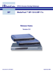
CP750 Front Panel
The CP750 front panel shown in Figure 1‐1 includes the following components from left to right:
•
Front‐panel menu navigation buttons
•
Status display
•
Mute button
•
Main fader knob
•
USB port for firmware upgrades and setup software
•
Seven buttons that select an input source: Digital 1, Digital 2, Digital 3, Digital 4, Multi-Ch
Analog, NonSync, and Mic
•
Four LEDs that indicate the presence of a Valid signal on each digital input. Digital 1 and Digital 4 have valid signals in Figure 1‐1.
Figure 1‐1
CP750
Digital Cinema Processor
Input Select
Digital 1
P
Figure 1-1
CP750 Front Panel
1.2.1
Front-Panel Menu Navigation Buttons
Digital 2
Digital 3
Digital 4
Multi-Ch
Analog
NonSync
Mic.
Valid
The menu control buttons to the left of the display, shown in Figure 1‐1, are used by both the operator and the service engineer to navigate front‐panel screen menus, select various menu options, and store setup data.
2
Dolby® CP750 Digital Cinema Processor Manual
CP750 Front Panel
The menu button is used to step through the menu list. Pressing and releasing the button once changes the display to the next menu item. Pressing and holding the button while rotating the main fader knob steps the display through all menu items.
The check mark button is used to accept the settings displayed on the front‐panel screen and store it in CP750 memory. Changes to settings occur immediately, but are not immediately saved. The button blinks when there are unsaved parameter changes. Caution: Do not disconnect power to the unit while the checkmark button is blinking. 1.2.2
Front-Panel Status Display
Day‐to‐day operation of the CP750 is performed through interaction with the front‐panel status display shown in Figure 1‐2.
Processing Display
The top line displays the processing being applied to the audio. The supported processes are:
•
Dolby Pro Logic
•
Dolby Pro Logic II
•
Dolby Digital
•
Dolby Digital Surround EX
•
Discrete
Volume Display
The main fader level is displayed as a two‐digit number. As with previous generations of Dolby cinema processors, a fader setting of 7.0 (0 dB) is the nominal correct operating level. 7.0 matches the level used during production of the motion picture.
Input Display
The bottom line of the display shows the type of audio being input.
Meter Display
The circle of lights surrounding the display text serves as channel meters when the CP750 is in use.
Dolby® CP750 Digital Cinema Processor Manual
3
Introduction
Figure 1‐2
Center
Left
Right
Processing
Volume
Input
Subwoofer
Left Surround
Figure 1-2
1.2.3
Right Surround
Front-Panel Display
Mute Button
Pressing the mute button shown in red in Figure 1‐1 fades the audio output to all channels without disturbing the current main fader setting. Fade‐in and fade‐out speeds are separately adjustable from 0.2 to 5 seconds, using the PC setup software. The mute button flashes red when activated.
1.2.4
Main Fader Knob
Use this knob to adjust the sound level. A fader reading of 7.0 is the nominal correct operating level. The main fader knob rotates continuously with no end stops. The knob is also used to adjust parameters during setup operations.
When the fader knob is rotated between readings of 0 and 4.0, the output level changes in 20 dB steps between –90 and –10 dB. When the fader knob is rotated between readings 4.0 and 10, the output level changes in 3.33 dB steps between –10 and –10 dB. Figure 1‐3 shows the characteristic graph.
4
Dolby® CP750 Digital Cinema Processor Manual
CP750 Front Panel
Figure 1‐3
10
3 1/3 db
per step
0
-10
-20
-30
Output
-40
Level (dB)
20 dB
per step
-50
-60
-70
-80
-90
0
1
2
3
4
5
6
7
8
9
10
Fader Level
Figure 1-3
1.2.5
Fader Characteristic
USB Port
The USB port is provided for connecting to a PC. You can use it either to set up the unit or to update the CP750 firmware. 1.2.6
Digital Input Selection Buttons
When you press any of the Digital 1, Digital 2, Digital 3, or Digital 4 push buttons, that button lights up, indicating that the selected input channel is active. Pressing one of these buttons selects a specific digital input source, as shown in Table 1‐1. The CP750 switches automatically between PCM and Dolby Digital bitstreams. Table 1-1
Digital Input Selection Button Functionality
Input Button
Digital 1 Digital 2 Digital 3 Digital 4 1.2.7
Input Source Selected
Selects the input signal from the 4xAES DIGITAL 1 connector (four‐channel pairs, 25‐pin D‐connector)
Selects the input signal from the 1xAES DIGITAL 2 connector (BNC)
Selects the input signal from the 1xAES DIGITAL 3 connector (BNC)
Selects the input signal from the 1xAES DIGITAL 4 connector (S/PDIF optical)
Valid Input LEDs
Each digital input push button has a green Valid LED located beneath it. These LEDs light up when the CP750 detects a valid signal on the respective input, whether or not the input is selected. Digital 1 and Digital 4 have valid signals in Figure 1‐1.
Dolby® CP750 Digital Cinema Processor Manual
5
Introduction
1.2.8
Analog Inputs
The CP750 has the three analog inputs, listed in Table 1‐2.
Analog Input Options
Table 1-2
Analog Input
Rear-Panel Input Source Selected
Multi-Ch Analog Selects the input signal from the MULTI-CHANNEL ANALOG INPUT connector (eight channels, 25‐pin D‐connector)
Selects the input signal from the NONSYNC INPUT L and R RCA jacks
Selects the input signal from the MIC. INPUT 3‐prong XLR connector
NonSync Mic. 1.3
CP750 Rear Panel
Figure 1‐4
CP750
Digital Cinema Processor
CAUTION
To reduce the risk of fire
replace only with same
type and rating
250V time-lag fuse.
FUSE T 3.15A L
5 mm x 20 mm
This Class A digital apparatus complies with Canadian ICES003.
Risk of electric shock.
Do not open.
UL
LISTED
Figure 1-4
4xAES IN
This equipment must be
earthed/grounded.
ETHERNET
RS-232
REMOTE
DIGITAL 1
1xAES IN
NONSYNC AUX
INPUT OUT
L
7 H/I
OUT
OPT IN
25
US
PROFESSIONAL AUDIO
EQUIPMENT
4J06
No user serviceable parts
inside. Refer all service
to qualified personnel.
BACK-UP
POWER
~ 50–60 Hz 30W
100–240 Vac
C
This device complies with Part 15 of the FCC Rules.
Operation is subject to the following two conditions: (1) this
device may not cause harmful interference, and (2) this
device must accept any interference received, including
interference that may cause undesired operation.
R
Dolby, Pro Logic and the double-D symbol
are registered trademarks of Dolby Laboratories.
ACT LINK
NOT ETHERNET
AUTOMATION
DIGITAL 2 DIGITAL 3 DIGITAL 4
8
MIC.
INPUT
MAIN
AUDIO OUTPUT
PUSH
MULTI-CHANNEL
MIC.
GAIN
ANALOG INPUT
CP750 Rear Panel
The CP750 rear panel, shown in Figure 1‐2, includes the following components:
•
AC input.
•
BACKUP POWER—4‐prong female XLR connector for use with the Cat. No. 994 •
Ethernet—RJ‐45 port for remote control through ASCII command strings, Dolby External Power Supply.
Digital Cinema Theatre Management Software, unit setup, and firmware updates. See Section 7.2.8 for details on the command strings.
Note:
•
The CP750 supports 10Base‐T and 100Base‐T data rates. Gigabit Ethernet data rate is not supported.
RS-232—9‐pin female D‐connector for control via ASCII command strings. 9600 baud, no parity, 1 stop bit. See Section 7.2.8 for details on the command strings. See Section 7.2.2 for pinout details.
•
REMOTE—RJ‐45 port for communication with the Cat. No. 868 Remote Fader. See Section 7.2.3 for pinout details. This is not an Ethernet connection but can be connected with any standard Ethernet cable.
•
4xAES IN—25‐pin female D‐connector labeled DIGITAL 1 carrying four digital channel pairs. See Section 7.2.4 for pinout details.
6
•
AUTOMATION—25‐pin female D‐connector for cinema automation control. See Section 7.2.5 for pinout details.
•
Two 1xAES IN—BNC connectors labeled DIGITAL 2 and DIGITAL 3.
•
OPT IN—Optical S/PDIF input connector labeled DIGITAL 4. •
NONSYNC INPUT—2 RCA jacks labeled L and R that accept 3 VRMS maximum input.
•
AUX OUT—RCA jacks labeled 7 and 8 always carry channel pair 7/8 of the 4xAES input. If present, HI and VI‐N signals likely use this pair.
Dolby® CP750 Digital Cinema Processor Manual
CP750 Rear Panel
•
H/I OUT—RCA jack for hearing impaired output. This is a center‐weighted sum of L‐C‐R.
1.3.1
•
MIC. GAIN—For adjusting the gain of the microphone pre‐amp.
•
MIC. INPUT—3‐pin female XLR connector for a PA or auditorium equalization microphone. Phantom power can be applied using the setup software.
•
MAIN AUDIO OUTPUT—25‐pin female D‐connector balanced audio output to the auditorium sound system. See Section 7.2.7 for pinout details.
•
MULTI-CHANNEL ANALOG INPUT—25‐pin female D‐connector carrying eight balanced analog channels. See Section 7.2.7 for pinout details.
AC Input
This is a simple unswitched IEC power inlet module.
1.3.2
Backup Power Port
This is a 4‐pin female XLR connector for use with the Cat. No. 994 External Power Supply.
1.3.3
Ethernet Port
This is an illuminated RJ‐45 10/100BASE‐T Ethernet port with activity LEDs, which provides an interface to a Dolby Digital Cinema network and also ASCII string commands over TCP to port 61408. You can also use this port for setup software and firmware upgrades. 1.3.4
RS-232 Serial Port
You can use this port for serial control using ASCII string commands. The equipment connected to this port should have its serial port set to 9600 baud, no parity, 1 stop bit. Use a pin‐to‐pin serial cable. The same control functions are available through the Ethernet port.
1.3.5
Remote Connector
This is not an Ethernet connection, but an Ethernet cable is used to connect to the Cat. No. 868 Remote Fader.
1.3.6
4xAES IN Connector
This 25‐pin female D‐connector, linked to the Digital 1 button, receives four AES/EBU streams. The four AES input signals must be time aligned with each other. Typically, this input connects to a Dolby Digital cinema server. It accommodates PCM audio at 96, 48, and 44.1 kHz, and 32 kHz (16, 20, and 24 bits) and Dolby Digital at all data rates and sample rates. The decoding of Dolby Digital is restricted to the first AES3 channel pair. This connector has a floating ground.
Dolby® CP750 Digital Cinema Processor Manual
7
Introduction
1.3.7
Automation Connector
This connector is used to select an audio input, to read back the currently‐selected input, and to remotely assert the mute command. The pinout is listed in Section 7.2.5. The automation subsystem is referenced to pin 12, Automation Return. This is the ground for these functions, and is connected to the ground of the CP750 only through a 1 k
resistor. An isolated power supply is provided so that connection to automation systems can be made without introducing hum due to ground loops.
Caution: The isolated power supply can only function properly if the Automation Return pin is within ± 5 Volts DC (or peak AC) of the CP750 chassis ground. The automation control system is designed to accept contact closure inputs. A closed contact asserts a command. The low side of the contact closing switch or relay should be connected to Automation Return.
Warning: UNDER NO CIRCUMSTANCES should power from an external source be supplied to any pin in this connector! Connecting external power is likely to damage the CP750.
1.3.8
1xAES IN Connectors
These BNC connectors are linked to the Digital 2 and Digital 3 buttons. They accommodate PCM audio at 96, 48, and 44.1, and 32 kHz (16, 20, and 24 bits) and Dolby Digital at all data rates and sample rates. A BNC male to RCA female adapter can interface with most consumer gear. These connectors have floating grounds.
1.3.9
Opt In Connector
This optical connector is linked to the Digital 4 button. It accommodates PCM audio at 96, 48, 44.1, and 32 kHz (16, 20, and 24 bits) and Dolby Digital at all data rates and sample rates.
1.3.10
NonSync Input Connector
2 RCA jacks labeled L and R that accept 3 VRMS maximum input.
1.3.11
Aux Out Connectors
These analog output represents channel pair 7/8 of the 4xAES input.
For the top output labeled 7, the source is Channel 7 of the 4xAES input. No equalization or level control is applied.
For the lower output labeled 8, the source is Channel #8 of the 4xAES input. No equalization or level control is applied.
8
Dolby® CP750 Digital Cinema Processor Manual
CP750 Rear Panel
1.3.12
H/I Out Connector
The hearing‐impaired output signal, on the female RCA connector labeled H/I Out, is unbalanced. It is a center‐weighted analog sum of the L, C, and R channels.
1.3.13
Mic. Gain
This multi‐turn trimpot adjusts the gain of the mic preamp. If you use the microphone input for public address purposes, adjust this control for the desired volume in the auditorium. If you use it only for cinema alignment purposes, the trimpot will be adjusted using the setup software.
1.3.14
Mic. Input
This input is for use with a balanced output microphone. Phantom power is provided, and can be turned on and off under software control using the setup software.
1.3.15
Main Audio Output Connector
This connector is an eight‐channel analog output (L, C, R, Ls, Rs, SW, Bsl, and Bsr), which is present on a male 25‐pin D‐connector (300 mV reference level). Bsl and Bsr channels are required for Dolby Digital Surround EX™ installations. For other installations these channel can be configured to represent channel pair 7/8 of the 4xAES input. These mutually exclusive options are configured in the setup software.
1.3.16
Multi-Channel Analog Input Connector
This connector is an eight‐channel analog input (L, C, R, Ls, Rs, SW, Bsl, Bsr) designed to receive 300 mVRMS (ref) inputs from external sources and inputs on a female 25‐pin D‐connector. These inputs are balanced and floating, but the common mode voltage must not exceed ± 6 V peak.
Send Us Your Feedback About This Section
If you have a question or comment about this chapter, send us an email. Dolby® CP750 Digital Cinema Processor Manual
9
Chapter 2
Installation
2.1
CP750 Floating Signal Grounds
The CP750 is designed to eliminate ground loops, which can occur when the unit is connected to multiple external equipment grounds. For this reason, the following CP750 connectors have isolated grounds:
•
MAIN AUDIO OUTPUT and MULTI-CHANNEL ANALOG INPUT—Eight‐channel input and output are balanced and floating. Note that a common mode signal between the CP750 audio outputs and its chassis ground must not exceed +6 V peak.
•
AUTOMATION connector—The common is floating and can be +5 V peak from the chassis ground.
•
1xAES IN BNC digital inputs—These are transformer isolated and their grounds can be +10 V peak from the chassis ground. •
4xAES D‐connector digital inputs—These are transformer isolated and their grounds can be +10 V peak from the chassis ground.
Note:
2.2
The RS‐232 input ground is connected to the CP750 chassis ground and is not floating.
Digital Audio Inputs
There are two professional interface standards for digital audio transmission: AES/EBU (also known as AES3) and AES‐3id. These methods stream the same digital data and professional audio header information over copper conductor links, but use different types of conductors and connectors.
AES/EBU uses a balanced connection (two conductors plus shield) with a characteristic input impedance of 110, a nominal peak‐to‐peak signal level of 5 V, and, most commonly, XLR connectors. The typical maximum transmission distance is 100 meters (328 feet). AES‐3id uses an unbalanced connection (one signal conductor plus shield) with a characteristic input impedance of 75, peak‐to‐peak signal level of 1 V, and BNC (“push and twist”) connectors. The typical maximum transmission distance is 1,000 meters (3,280 feet).
Professional digital audio equipment typically uses the AES/EBU method because balanced operation yields superior noise immunity, as it does with analog audio signals, and because XLR connectors are the standard on analog professional audio equipment.
Professional video equipment typically uses the AES‐3id interface, with BNC connectors. As with XLR connectors on professional audio equipment, the adoption of BNC connectors for the audio on professional video equipment stems from their use for the video signal. Also, the unbalanced AES‐3id signal can connect to more than one piece of Dolby® CP750 Digital Cinema Processor Manual
11
Installation
equipment by using the loop‐through connectors available on some devices. The signal is robust for long cable runs.
2.2.1
Consumer Interface Standards for Digital Audio
The consumer interface standard for digital audio transmission is S/PDIF (IEC 61937). S/PDIF uses coaxial unbalanced connections (one signal conductor plus shield) with a characteristic input impedance of 75 with RCA (phono) connectors, or a fiber‐optic cable link. The unbalanced coaxial connection has a peak‐to‐peak signal level of 0.5 V. The typical maximum transmission distance is 10 meters (33 feet). Although S/PDIF‐specific cables with suitable connectors can be purchased, you can also obtain good results using high‐quality 75 video cable with the appropriate connectors and/or adapters.
2.2.2
Cable Issues
Even in digital audio, noise‐free signals are very important. The cable used for digital signals is specifically designed for such use, although it looks the same as the cable used for analog audio or video signals. Any professional audio equipment or broadcast supply company can provide 110 cable with connectors (or without, if you’d like to terminate them yourself) for AES/EBU connections, and high‐quality 75 video cables with BNC connectors for AES‐3id connections. Use of cables or connectors not designed for digital transmission or with incorrect impedance compromises the integrity of the bitstream. This can result in unreliable hardware interconnections, especially with long cable runs.
2.2.3
Multiple Sources: Conversion Between Interface Standards
Although some details of the bitstreams used in the AES and S/PDIF standards are different, the audio information is exactly the same. As a result, most audio equipment accepts either standard with no need to convert the bitstream itself; this is the case with the CP750. However, if you intend to connect sources across different types of digital audio inputs, do not attempt to convert a digital interface type by directly wiring an XLR connector to a BNC or RCA plug. This causes an impedance mismatch and signal reflections, resulting in digital waveform degradation. This may appear to work, but the results are unreliable and dropouts occur.
For conversion between the AES‐3id and S/PDIF formats, you can use high‐quality RCA‐to‐BNC adapters because the cable and impedance are both the same (75).
For conversion between the AES/EBU and AES‐3id or AES/EBU and S/PDIF formats, a simple and economical method uses inline transformers. These devices perform the necessary impedance and balanced/unbalanced conversion. Table 2‐1 shows some examples of suitable adapters. The unbalanced connector in these examples is BNC. You can add BNC‐to‐RCA adapters for connecting to consumer S/PDIF connections. The following units use passive circuitry.
Table 2-1
Examples of Available Balanced/Unbalanced Adapters
Adapter Type
XLR female 110 in to BNC female 75 out
BNC female 75 in to male XLR 110 out
12
Neutrik®
NA‐BF
Canare®
BCJ‐XJ‐TRA
NA‐BM
BCJ‐XP‐TRA
Dolby® CP750 Digital Cinema Processor Manual
Mounting the CP750
Higher‐priced units incorporating active circuitry are also available. These offer additional features such as multiple inputs, inputs for optical connections, and multiple outputs.
2.3
Mounting the CP750
To avoid heat or hum pickup problems, do not mount the CP750 immediately above or below power amplifiers. Locate power amplifiers away from the CP750 to avoid hum pickup problems. Always leave a 1‐U space (43 mm, or 1.75 in) above and below the CP750 to provide adequate ventilation. Install an air guide or baffle to deflect hot any air coming from equipment below the CP750.
To ensure good ground contact, install a star washer on at least one (and preferably all) rack‐mounting screws as shown in Figure 2‐1. This will also aid in the prevention of electrical noise problems.
Figure 2‐1
Figure 2-1
Star Washers and Rack-Mounting Screws
Proper shielding and termination of cables and cable assemblies are also very important. Follow the methods shown in the wiring diagrams.
2.4
Connections
To connect the CP750 to your auditorium equipment, refer to Figure 2‐2 . For proper operation in locations where there is considerable interference, strictly adhere to the cable types, lengths, and pin assignments. Shields must connect only to the chassis and should not be paralleled with the negative side of inputs or outputs.
Connector pinouts are listed in Section 7.2.
2.5
Fuse Information
The CP750 uses a universal‐switching power supply that handles the full range of nominal mains voltages between 100 and 240 VAC, and any frequency between 50 and 60 Hz. If a power supply fuse blows, do not attempt to replace it. Instead, contact Dolby Laboratories.
Dolby® CP750 Digital Cinema Processor Manual
13
Installation
2.6
Mains Power Wiring
In some countries, the primary mains cable may not have a connector fitted. Nonterminated leads must be properly wired to an approved mains connector in accordance with the following international code:
•
Brown wire: live or hot
•
Blue wire: neutral
•
Green wire: mains ground
Warning: If you are uncertain about the wiring of your AC mains outlet, do not use it. Consult a qualified electrician.
2.7
Cable Diagram
The cable diagram for the CP750 rear panel is on page 15.
Send Us Your Feedback About This Section
If you have a question or comment about this chapter, send us an email. 14
Dolby® CP750 Digital Cinema Processor Manual
Installation
Cable Diagram
Figure 2‐2
Notes:
Unbalanced Input amplifier
one channel shown, applicable to all
Surround Speakers
PA Microphone Input
(Or Mic-multiplexer for setup)
Screen Speakers
black
Hearing
Impaired
System
red
Surround EX
Speakers
{
Digital Inputs:
PCM
Dolby Digital ( AC-3)
L+C+R
{
{
{
1. Follow all local electrical and building codes.
Red: 8
BSR
BSL
Red: 19
Black: 6
Red: 16
Black: 3
This device complies with Part 15 of the FCC Rules.
Operation is subject to the following two conditions: (1) this
device may not cause harmful interference, and (2) this
device must accept any interference received, including
interference that may cause undesired operation.
CAUTION
To reduce the risk of fire
replace only with same
type and rating
250V time-lag fuse.
FUSE T 3.15A L
5 mm x 20 mm
This Class A digital apparatus complies with Canadian ICES003.
Risk of electric shock.
Do not open.
UL
LISTED
NONSYNC AUX
INPUT OUT
L
7
4xAES IN
This equipment must be
earthed/grounded.
ETHERNET
REMOTE
DIGITAL 1
NOT ETHERNET
AUTOMATION
RS-232
1xAES IN
OPT IN
25
US
PROFESSIONAL AUDIO
EQUIPMENT
4J06
No user serviceable parts
inside. Refer all service
to qualified personnel.
BACK-UP
POWER
~ 50–60 Hz 30W
100–240 Vac
C
3. For two-conductor with shield wiring, use
Belden 8451 two-conductor shielded cable or
equivalent: tinned copper, twisted pair, 22 AWG
stranded tinned copper drain wire, aluminumpolyester shield, 100 percent shield coverage,
conductor to conductor (111 pF per meter).
4. All shields must be connected to the chassis of
the CP750 or DSP100/DSS200 rather than to
circuit (audio) ground. This achieves the RF
interference immunity required by European EMC
standards. For D-connectors, a metal housing
must be used and the shields must be connected
4X AES Source
Eight-channel PCM
from Server
CP750
Digital Cinema Processor
2. Use earthed (grounded) conduit wherever
possible. Avoid routing signal wiring near electric
motors, rectifiers, power wiring, dimmer wiring, or
other sources of electrical noise.
Dolby, Pro Logic and the double-D symbol
are registered trademarks of Dolby Laboratories.
DIGITAL 2 DIGITAL 3 DIGITAL 4
MAIN
AUDIO OUTPUT
PUSH
MULTI-CHANNEL
MIC.
R
ACT LINK
MIC.
INPUT
H/I
OUT
8
GAIN
ANALOG INPUT
F9110270_1A.CDR
Auditorium Network
Cat. No. 868 Remote Fader
(Optional)
Figure 2-2
Figure 2‐3
15
Automation
Input
{
Mic.
NonSync
Multi-Ch Analog
Digital 4
Digital 3
Digital 2
Digital 1
RS
LS
16 BSL
19 BSR
CD or DVD Player
Non-sync
Source
{
Cat. No. 994
Back-up Power Supply
( Optional)
Eight-channel Analog Input
(all unlabeled pins are chassis ground)
normal operating level = 300 mV
H/I OUT channel 7 (if present)
CP750
INSTALLATION WIRING
CP750 Inputs and Outputs
Dolby® CP750 Digital Cinema Processor Manual
Chapter 3
Installing, Launching, and Connecting
the Setup Software
The CP750 is designed and built to be set up and administered remotely by software. Once installed and configured, the CP750 remote application gives you access to all of the unit’s functions.
Begin by installing the software on a PC, which you can connect to the CP750 with a USB cable.
3.1
System Requirements
The CP750 setup software runs on Microsoft® Windows® XP and Windows Vista. 3.2
Installing the Software
To install the CP750 setup application, follow these steps:
1.
Open the CP750 Setup folder and run CP750Setup_x_x_x.exe. This file is named with the current software version number.
The installer opens displaying the screen shown in Figure 3‐1.
Figure 3‐1
Figure 3-1
Installer Welcome Screen
2.
Select the desired language.
3.
Follow the screen prompts until the installation is complete.
Dolby® CP750 Digital Cinema Processor Manual
17
Installing, Launching, and Connecting the Setup Software
3.3
Connecting the Hardware
There are three ways to connect computer hardware to the CP750.
3.4
•
The USB port on the front panel of the unit, shown in Figure 1‐1, is expressly designed for easy connection to laptop computers with a standard A to B cable. •
You can connect a pin‐to‐pin serial cable to the RS-232 connector on the unit rear panel. •
You can connect directly to the Ethernet connector on the unit rear panel. If your laptop supports Gigabit Ethernet, use a standard Ethernet cable. Otherwise, use a crossover cable.
Launching the Setup Application
To launch the CP750 setup application, click the Start button and scroll to Programs. In the Dolby folder, double‐click Dolby CP750 Setup. The Dolby® CP750 setup window appears, as shown in Figure 4‐1.
3.5
Connecting to a Local or Remote Device
You can use the setup software Action menu, shown in Figure 3‐2, to connect to a local or a remote device. Figure 3‐2
Figure 3-2
Action Menu
These options allow you to connect to a CP750 that is either connected to your PC (local device) or connected to an Ethernet network (remote device). If you select Connect to remote device, the system prompts you to enter an IP address.
You must change your laptop’s TCP/IP properties to communicate properly with the CP750 when connecting the setup software to a CP750 using a PC Ethernet connection. We recommend the following TCP/IP settings to enable your PC to communicate with a CP750 using its default setting.
IP address: 192.168.1.200
Subnet mask: 255.255.255.128
Default gateway: 192.168.1.129
Note:
18
The CP750 default IP address (for connecting) is 192.168.1.136.
Dolby® CP750 Digital Cinema Processor Manual
Connecting to a Local or Remote Device
Send Us Your Feedback About This Section
If you have a question or comment about this chapter, send us an email. Dolby® CP750 Digital Cinema Processor Manual
19
Chapter 4
Configuring the CP750 Software
4.1
Using the Application Tabs to Configure a CP750
Each setup application tab controls a different part of the application’s function. They are discussed separately in the following sections.
4.1.1
•
Profile Tab—Lets you enter identifying information that is important for service calls and technical support
•
Network/Time Tab—Lets you specify unit addresses and connections
•
General Settings—Lets you define a power‐on mode, a subwoofer filter frequency, and a surround delay for the CP750. •
Input Settings—Lets you define attributes and processing for each input
•
Alignment—Lets you optimize the sound in the auditorium. This important topic is described in detail in Chapter 5.
Profile Tab
When you launch and connect the CP750 setup software, the application opens with the Profile tab active, as shown in Figure 4‐1. Figure 4‐1
Figure 4-1
Profile Tab
Here you enter identifying information about the auditorium equipment. This system information is particularly important if a service call is ever necessary. The key items are:
•
CP750 Serial Number—Read the number from the back of the CP750 unit.
Dolby® CP750 Digital Cinema Processor Manual
21
Configuring the CP750 Software
•
Theatre Name–This must match the name registered in your Theatre Management Software (TMS).
•
Auditorium Number–This must match the number assigned to the Show Player.
•
Cinema Processor—Enter a name for your CP750. •
Digital Cinema System—Identifying numbers for your cinema processing equipment.
•
Digital Cinema Projector—Identifying information for your projector.
•
Input Descriptions—The identifying text you enter here is repeated as the titles of the Input Settings tab.
Tip: Assigning clear names to the digital inputs is an easy way to prevent input selection errors.
The Profile tab displays the current network settings, but you can modify them only on the Network/Time tab.
4.1.2
Network/Time Tab
The Network/Time tab, shown in Figure 4‐2, lets you configure the CP750 Ethernet settings and time and date settings. The host name and IP address are echoed, read‐only, on the Profile tab. Network configuration and status are also available though the ASCII control interface.
Ethernet Settings
By default DHCP is turned off, and entries follow the Dolby® Digital Cinema private network address naming convention in which the third octet indicates the auditorium number:
•
Host Name: CP750xxxxx
•
IP Address: 192.168.x.136 •
Subnet Mask: 255.255.255.128
•
Default Gateway: 192.168.x.129 If you are using the Dolby TMS you need only enter the auditorium number in the third triad of the IP Address and Default Gateway fields. DHCP
As soon as you click Enable, the IP Address, Subnet Mask, and Default Gateway change to 0.0.0.0 while the unit searches for a server and acquires valid addresses. This search and acquisition process may take up to 30 seconds. If no server is found, the displays stay at 0.0.0.0 past 30 seconds.
22
Dolby® CP750 Digital Cinema Processor Manual
Using the Application Tabs to Configure a CP750
Figure 4‐2
Figure 4-2
Network/Time Tab
If you make any changes, the system highlights two action buttons. Click one to either Discard Changes or Apply Changes.
Time and Date
You can change the time manually by dialing with the arrows in the Apply Time field.
You can also load the local time from a server by clicking the Load Local Time button.
You must click Apply to make changes to the unit’s stored date and time.
4.1.3
General Settings
This tab, shown in Figure 4‐3, lets you set four system attributes:
•
Power‐on Mode
•
Surround Delay
•
Main Audio Output Configuration
•
Mute Duration
Dolby® CP750 Digital Cinema Processor Manual
23
Configuring the CP750 Software
Figure 4‐3
Figure 4-3
General Settings Tab
Power-on Mode
The Power‐on Mode selects the input that is activated when the CP750 unit is powered on. You can select Last Setting, or any of the inputs.
Surround Delay
The setup application can calculate and set the General surround delay value based on theatre measurements entered here. Measurements may be entered in feet or meters. 1.
Click Feet or Meters to choose a unit of measure.
2.
Enter a Distance from screen to rear wall of theatre value between 0 and 200. 3.
Enter an Average distance between left and right Surround channels value between 0 and 140.
4.
Click Calculate.
The General value is adjustable from 0 to 150 ms in 1 ms steps. The display shows a marker every 10 ms.
After you set the general surround delay for digital material, set the Pro Logic/Pro Logic II value which is applied to analog material. The minimum value for this slider is 20 ms because this value should always be 20 ms higher than the General value.
Main Audio Output Configuration
You can indicate that your auditorium is set up to use Dolby Digital Surround EX™ . 24
Dolby® CP750 Digital Cinema Processor Manual
Using the Application Tabs to Configure a CP750
Mute Duration
The Fade In and Fade Out slider each have a range of 0.2 to 5.0 seconds in 0.1 second steps. Set a value either by moving the slider.
4.1.4
Input Settings
The Input Settings tab of the set up application consists of a separate tab for each input described separately in the sections that follow.
4.1.5
Digital Input 1
Figure 4‐4 shows the Digital Input 1 tab. The tab title is repeated from the Digital 1 input description on the Profile tab.
Figure 4‐4
Figure 4-4
Digital Input 1 Tab
On the Digital Input 1 tab you can configure:
•
Global Audio Delay
•
Mute Main Bsl/Bsr Output Pins
•
Fader Preset
•
PCM Channel Assignment
•
PCM Decode Mode
•
PCM Processing Mode
•
Dolby Digital Decode Mode
•
Dolby Digital Dialogue Normalization
Dolby® CP750 Digital Cinema Processor Manual
25
Configuring the CP750 Software
Global Audio Delay
The Global Audio Delay field specifies an audio delay in addition to the CP750 decoding delay of approximately 7 ms for 4xAES PCM. Use this function to synchronize the audio with the video from digital cinema projectors, which add a video processing delay. Use the up and down arrows to set the Global Audio Delay between 0 and 250 ms. This delay value is set independently for each digital input.
Note:
Systems that use an external video scaler may add another decoding delay.
Mute Main Bsl/Bsr Output Pins
Choose Enable to mute these pins if your auditorium does not use them. Fader Preset
To use the Fader Preset feature, choose Enable and indicate a value on the slider. This ensures that inputs play at correct values each time they are selected. PCM Channel Assignment
The analog audio output channels (L, R, C, LFE, Ls, Rs) are always fixed and hardwired to a cinema processor. However, when a PCM bitstream’s input‐channel mapping is not a default SMPTE configuration (L/R, C/LFE, Ls/Rs), you must reassign the input channels to match the hardwired audio outputs. For channel reassignment, the surround delay and the LFE filter are always tied at the output, and therefore cause no problem.
To reassign the input channels, use the drop‐down Assigned To menu for each of the AES Input channels or click one of the three preset buttons (L/R C/Sw Ls/Rs; L/C R/Ls Rs/Sw; or L/Ls C/Rs R/Sw). To activate your changes, click the Apply changes button. To cancel your changes, click the Discard changes button.
PCM Decode Mode
You can select one of four surround channel processing options:
•
None •
Pro Logic •
Pro Logic II •
Surround EX PCM Processing Mode
You have three choices of mode:
26
•
Minimum Latency—When selected, this default mode provides the quickest audio processing (approximately 7 ms) for PCM audio.
•
Silent Switch—When selected, the CP750 constantly checks for transitions between PCM and coded audio, and switches between the two silently. This mode adds a 40 ms latency to the audio processing (for a total latency of approximately 47 ms).
Dolby® CP750 Digital Cinema Processor Manual
Using the Application Tabs to Configure a CP750
•
Mute—When selected, PCM audio is muted. Dolby Digital plays normally.
Note:
Both Minimum Latency and Silent Switch automatically switch between PCM and coded audio. Minimum Latency may produce an audible snat during the transition.
Dolby Digital Decode Mode
You choose how the system decodes a two‐channel input stream. There are four options: •
Auto •
Pro Logic •
Pro Logic II •
Surround EX Auto decode mode follows the surround metadata parameter embedded in the coded bitstream. There is no metadata in PCM audio. If you choose Pro Logic or Pro Logic II decoding, your choice overrides the presence or absence of surround metadata in two‐channel coded bitstreams.
Dolby Digital Dialogue Normalization
When enabled, this option sets the decoder level shift according to the metadata embedded in the Dolby Digital bitstream. The default is Disable.
4.1.6
Digital Inputs 2, 3, and 4
The options available on these three tabs are identical. Figure 4‐5 shows the Digital Input 2 tab. The tab titles are repeated from the input descriptions on the Profile tab.
Dolby® CP750 Digital Cinema Processor Manual
27
Configuring the CP750 Software
Figure 4‐5
Figure 4-5
Digital Input 2 Tab
For these inputs you can configure:
•
Global Audio Delay
•
Fader Preset
•
PCM Decode Mode
•
PCM Processing Mode
•
Dolby Digital Decode Mode
•
Dolby Digital Dialogue Normalization
The options for Global Audio Delay, Fader Preset, PCM Processing Mode, Dolby Digital Decode Mode, and Dolby Digital dialogue normalization and are identical to those on the Digital Input 1 tab.
PCM Decode Mode
There are three decoding options for two‐channel PCM streams: 4.1.7
•
None
•
Pro Logic •
Pro Logic II Analog Input
Figure 4‐6 shows the Analog Input tab. 28
Dolby® CP750 Digital Cinema Processor Manual
Using the Application Tabs to Configure a CP750
Figure 4‐6
Figure 4-6
Analog Input Tab
On this tab you can set:
•
Global Audio Delay
•
Mute Main Bsl/Bsr Output Pins
•
Fader Preset
•
PCM Channel Assignment
•
PCM Decode Mode
These choices operate identically to those on the Digital Input 1 tab. 4.1.8
Nonsync Input
On the Nonsync Input tab, shown in Figure 4‐7, you can choose:
•
Global Audio Delay
•
Fader Preset
The options operate identically to those on other tabs.
You can choose any of six supported formats for PCM:
•
Format 60 Nonsync
•
Format 70 Mono CS
•
Format 71 Mono C
•
Format 73 Pro Logic LCR
•
Format 74 Pro Logic with no subwoofer
•
Format 75 Pro Logic with a subwoofer
You can also set an Input Trim using the slider.
Dolby® CP750 Digital Cinema Processor Manual
29
Configuring the CP750 Software
Figure 4‐7
Figure 4-7
Nonsync Input Tab
4.1.9
Mic Input
On the Mic Input tab, shown in Figure 4‐8, you can choose:
•
Global Audio Delay
•
Fader Preset
The options operate identically to those on other tabs. The PCM Channel Assignment field allows you to assign the microphone input either the Center channel or the Surrounds.
In the Phantom Power field, you can enable phantom power to the microphone as needed.
Figure 4‐8
Figure 4-8
30
Mic Input Tab
Dolby® CP750 Digital Cinema Processor Manual
Saving Settings in a Configuration File
4.2
Saving Settings in a Configuration File
When you have completed configuration work on the CP750, you can save your settings to a .dlb parameter file. We recommend saving configuration files for use in the event your unit ever needs to be replaced.
Caution: Take care to identify the settings file clearly, and store it separately from software update files, which also use the .dlb extension.
Chose Save in the File menu as shown in Figure 4‐9, browse to the location on your PC where you want to save the file, enter a file name, and click Save.
Figure 4‐9
Figure 4-9
Selecting Save in the File Menu
To modify an existing .dlb file and save it under a different name, open the file, then select
Save As in the File menu.
4.3
Loading a Saved Configuration File
A CP750 can be restored from an existing .dlb configuration file.
To do so, choose Open in the File menu of the setup application, browse to the desired .dlb file on your PC, and open it.
Figure 4‐10
Figure 4-10 Selecting Open in the File Menu
4.4
Using Expert View
When you choose Expert View on the Window menu, all the CP750 parameters and command strings are available as shown in Figure 4‐11.You can modify a parameter highlighted in green by double clicking it and typing a new value. To return to the tab display, reselect Expert View.
Dolby® CP750 Digital Cinema Processor Manual
31
Configuring the CP750 Software
Figure 4‐11
Figure 4-11 Expert View Window
4.5
Updating the CP750 Firmware
When you choose Update Software on the Action menu, the setup software closes and Dolby Software Update automatically opens and connects. You can then update the CP750 firmware by following these directions. When the update is completed, Dolby Software Update closes and the setup software opens and reconnects.
To update the CP750 firmware:
1.
Obtain the latest version of the CP750 setup application from Dolby Laboratories and install it on your PC.
2.
Obtain the .dlb update file from Dolby Laboratories and copy it to your PC.
3.
Connect your PC to the USB port on the CP750 front panel. 4.
Click Update Software on the Action menu to begin the update process. The Dolby Software Update window, shown in Figure 4‐12, opens.
32
Dolby® CP750 Digital Cinema Processor Manual
Updating the CP750 Firmware
Figure 4‐12
Figure 4-12 Dolby Software Update Screen
5.
6.
Click Browse to find the .dlb update file on your PC, then click Open.
Click Update.
After a few seconds, a progress bar displays the status of the update process. When the process is completed, the CP750 automatically reboots with the updated firmware.
You must close the Dolby Software Update window manually. Send Us Your Feedback About This Section
If you have a question or comment about this chapter, send us an email. Dolby® CP750 Digital Cinema Processor Manual
33
Chapter 5
Aligning the Auditorium
The CP750 allows you to quickly and easily optimize the sound quality in the auditorium. The alignment process is discussed in the following sections:
5.1
•
Checking Theatre Equipment
•
Microphone Placement
•
Initial Setup
•
Calibrating the Internal SPL Meter
•
Initial Output‐Level Adjustment
•
Room Equalization
•
Final Output‐Level Calibration
•
Final Sound Check
•
Nonsync Level Adjustment
Checking Theatre Equipment
Thoroughly check the loudspeakers and power amplifiers for any sources of poor performance, using the checklists below as a guide.
5.1.1
Speakers
•
Check loudspeaker cable condition and confirm that the cables are the correct gauge for the impedance of the speakers and the length of the run.
•
Check that the speakers are connected to the correct power amp channel.
•
Check for leaks in the low‐frequency driver cabinet which may sound like rattles.
•
Check for loose bolts or other hardware.
•
Check the speakers with an ohmmeter. If one channel requires markedly more equalization than the other, or if one speaker overloads at lower levels than the other speakers, an open driver circuit could be the cause. In systems with pairs of drivers, one voice coil of the pair may be open but the system will still function.
•
Check for missing drivers or other components.
•
Verify that crossover settings matching the type of drivers in use and the acoustics of the theatre. The high‐frequency driver level control must be set for the best possible frequency response before you attempt any equalization. This is especially true if the system uses active crossovers with biamp equipment.
•
Check for proper polarity between the low‐ and high‐frequency drivers, and between the channels.
•
Ensure that the speakers are correctly aimed into the auditorium, and that they are not obstructed by the screen frame, struts, or other objects.
Dolby® CP750 Digital Cinema Processor Manual
35
Aligning the Auditorium
5.1.2
5.1.3
Amplifiers
•
Check for distortion.
•
Check for gross gain differences among amplifiers. If one amplifier differs in performance from the others, it should be checked and repaired.
•
Check for blown fuses.
•
Ensure that there is good air movement through power amplifiers.
•
Check any air filters.
Air Conditioning
If air‐conditioning noise is audible in the theatre, arrange for lubrication of the motor and fan bearings, adjustment of belts and drives, and cleaning of filters to minimize ambient noise.
5.2
Microphone Placement
Position a microphone multiplexer in the center of the auditorium listening area. Place each microphone in the reverberant field rather than in an area that receives the most direct energy from the speakers. In addition, avoid perfect symmetry. Arrange the microphones so that they do not form a square or rectangle parallel to the sides of the room. Take care not to place any of the multiplexing microphones on the auditorium center line. Standing waves and nodes can cause measurement errors. During final SPL calibration, microphone number 1 should be placed two‐thirds of the distance from the front speakers to the rear, at the exact side‐to‐side center of the room, approximately five feet above the floor level, and rotated 45 degrees upward toward the screen. (Some multiplexer microphones are designed to be pointed directly at the ceiling.) Placement of this microphone is important for output level adjustments.
Figure 5‐1
Figure 5-1
Microphone Placement for Equalization
If a single microphone is used, which we do not recommend, use the number 1 position detailed above, but place it slightly off center during equalization.
Route the output cable to the CP750 and connect it to the Mic. Input connector on the CP750 rear panel. Note:
36
Many microphones require phantom power, which can be enabled in the CP750 setup software.
Dolby® CP750 Digital Cinema Processor Manual
Initial Setup
5.3
Initial Setup
Prepare for the alignment process with the following steps:
1.
Set all the gain controls on all power amplifiers to known, repeatable settings. The preferred setting for most amplifier gain controls is the maximum. If a different setting is required in order to optimize the noise performance of the system, the controls should be locked in position or marked clearly.
Caution: The following process causes the CP750 to output pink noise to the power amplifiers. The CP750 output levels may be set too high. If you are unsure of the settings on your unit, turn off the power amplifiers before calibrating SPL. Then, select and observe the present output level adjustment settings. 2.
Set up your crossovers if present.
3.
Apply power to the CP750. 4.
Launch the CP750 Setup Software, connect to the unit, and click Alignment. The software displays a warning that entering alignment mode will disturb auditorium audio.
5.
Click Continue in the warning tab that appears to begin the auditorium alignment process.
The Room Levels tab appears active. Room Levels shows a summary of current settings, allows you to calibrate the internal SPL meter, allows you to choose a channel with which to work, or to adjust any channel’s level with a slider. Each increment of the displayed relative number from a value of 1 to 127, represents an increment of approximately 0.25 dB of range adjustment. Figure 5‐2 shows an example of the tab before the SPL is calibrated.
Dolby® CP750 Digital Cinema Processor Manual
37
Aligning the Auditorium
Figure 5‐2
Figure 5-2
5.4
Alignment Tab Showing Room Levels
Calibrating the Internal SPL Meter
You must calibrate the CP750’s internal SPL before proceeding with alignment.
1.
To start the process, click C under Signal Generator Enable to activate the Center channel.
2.
Select Pink Noise from the Signal Mode drop‐down list. Pink noise is sent to the Center channel speaker.
Note:
3.
The CP750 is shipped from the factory with the Mic. Input level control set to the minimum.
Check the microphone level to be sure it appears in the target range as shown in Figure 5‐2.
If necessary, adjust the Mic. Gain on the rear panel of the CP750 until the level is within the target range. 38
Dolby® CP750 Digital Cinema Processor Manual
Initial Output-Level Adjustment
4.
With a sound pressure level meter, measure the noise level in the room. Hold the sound pressure level meter near the location of mic 1, discussed in Section 5.2.
5.
Enter the measured value into the Measured Value field.
6.
Wait while the system automatically calibrates to the room reading. The calibration is retained in CP750 memory and can be used in future alignments. However, it is advisable to recalibrate the system when rearranging microphones because the sound pressure level varies slightly with microphone placement.
5.5
Initial Output-Level Adjustment
Next, adjust each channel slider to make sure the pink noise is audible and to achieve a reasonable sound pressure level in the auditorium. It is not necessary to set exact levels because the levels will change slightly during equalization. Exact output level adjustment is performed after equalization.
Note:
5.5.1
For this and all other adjustments using sliders, use the slider to get close to the optimal value. Use the up and down arrow keys to make fine adjustments. Setting Main Channel Levels
When the CP750 is first installed, you must repeat these steps for each channel. Values are adjusted on the Channel Tune tab after a channel is chosen. Figure 5‐3 shows an example with the Center channel selected.
1.
Click a channel radio button to make it active and lock pink noise to it. 2.
Check the level indicated underneath the Channel Level slider, and move it up or down until the measured level reads 85 dB.
3.
Repeat steps 1 and 2 for the R and L channels, setting the Channel Level to 85 dB.
4.
Repeat steps 1 and 2 for the Ls, Bsl, R, and Bsr channels, setting each to read 82 dB.
Dolby® CP750 Digital Cinema Processor Manual
39
Aligning the Auditorium
Figure 5‐3
Figure 5-3
5.5.2
Channel Tune Tab Showing the Center Channel
Subwoofer Levels
After the last surround channel is adjusted, click LFE to work with it. Pink noise is now present on the Subwoofer channel only (140 Hz bandwidth for EQ and level setting screens). The LFE has distinct options that appear on the Channel Tune tab, as shown in Figure 5‐4.
40
Dolby® CP750 Digital Cinema Processor Manual
Room Equalization
Figure 5‐4
Figure 5-4
Channel Tune Tab Showing LFE EQ
Initial subwoofer level setting uses a blue reference line displayed on the LFE Channel Tune tab, established from the Center channel pink‐noise level. Using the Channel Level slider, adjust the level, moving the average subwoofer RTA display to match the reference line on the screen as closely as possible. Final subwoofer level adjustments for both digital and Dolby® Pro Logic® signal paths are carried out later, after the room is equalized.
5.6
Room Equalization
Room equalization is performed using the RTA built into the CP750. The desired result is a frequency response that closely matches the “x‐curve” overlay (SMPTE 202M‐1998). Results achieved within ±3 dB of the x‐curve are considered within tolerance of the specification. Small diameter, pressure calibrated microphones are preferred for accuracy over large diameter types. Use of a microphone multiplexer will accommodate spatial Dolby® CP750 Digital Cinema Processor Manual
41
Aligning the Auditorium
averaging of different positions within the room, which is recommended for best results. Follow this sequence:
1.
5.6.1
Perform coarse adjustments of each channel using the Bulk EQ Bass and Treble sliders. 2.
Perform fine adjustments of each band using the 27‐band one‐third‐octave equalizer. 3.
Perform LFE channel equalization by setting the frequency, Q (width), and level of cut, using the single‐band parametric equalizer. Setting Bulk EQ
This process simultaneously adjusts all bass or all treble frequencies. It is important to adjust both of these prior to adjusting the individual one‐third octave bands.
Bass Level
The Bass level on the Channel Tune tab is adjustable from –6 to +6 dB in 0.2 dB steps. Using the slider, approximate the reference curve as closely as possible.
Treble Level
The Treble level is adjustable from –10 to +10 dB in 0.2 dB steps. Using the slider, approximate the reference curve as closely as possible. Treble Frequency Corner
The Treble corner frequency can be set to 1, 2, 3, or 4 kHz, and applies to all channels. Choose the setting that matches the reference curve most closely.
5.6.2
Using EQ Assist
The EQ Assist feature automatically adjusts the frequency response to the x‐curve. Use this feature with care since it adjusts adjacent bands as necessary (even to extremes) to achieve the exact x‐curve. The EQ Assist feature does not adjust to room anomalies as a human operator can, avoiding overcompensation in any frequency bands.
Note:
If you use this feature, be sure to use it after adjusting the bass and treble bulk EQ. To prevent overcompensation for possible speaker problems, the 20, 25, 30, 40, 50, and 63 Hz, as well as the 12.5 and16 kHz, bands are not automatically adjusted. You must adjust these bands manually.
5.6.3
Making Fine Adjustments to Individual Bands
Observe adjacent band effects when adjusting individual frequencies. Be aware of frequency bands that are very different from neighboring bands, and use caution so as not to overcompensate. (Major differences could be the result of a room node at the particular microphone location.) Adjust each frequency band as necessary to achieve a smooth EQ with results nearing the x‐curve overlay. The goal is to achieve (or come close to) the 42
Dolby® CP750 Digital Cinema Processor Manual
Final Output-Level Calibration
x‐curve without overcompensating. Remember that the SMPTE tolerance is ±3 dB, although closer results are often easily achieved.
5.6.4
Adjusting LFE Channel EQ
Begin with zero cut and observe the worst peak within the spectrum. Adjust the Center slider until the frequency matches the peak, and then adjust the Cut to flatten that region. Adjust the Q (width) and Cut, until the smoothest response is achieved.
Equalization facilities for the subwoofer channel are different than for the other channels. The process in this manual is designed to correct the principal room resonance in the operating range of the subwoofer. The subwoofer equalizer is a cut‐only filter, with adjustable center frequency (25 to 125 Hz), Q (center width, selectable among four values), and amount of cut (0 to 12 dB). After all the full‐range channels have been equalized, follow these steps:
1.
Click LFE to make it the active channel. 2.
Using the slider reduce Cut to 0 dB. This disables EQ so that you can determine the low‐frequency resonant peak to be equalized. Note the band where the unequalized peak appears.
3.
Using the slider increase Cut to its maximum, 12 dB.
Using the Center slider moves the dip in the frequency response along the frequency axis of the RTA display.
5.7
4.
Adjust the center frequency so that the center of the dip is in the same band as the peak displayed in the previous unequalized frequency response.
5.
Using the Cut slider, slowly reduce the amount of cut to flatten the dip. The center of the dip should be at the same level as the skirts.
6.
Click to check other Q values for the flattest possible frequency response. Final Output-Level Calibration
Once room equalization is complete, the sound pressure level in the theatre can be set accurately.
5.7.1
Main Channels
If a microphone multiplexer is being used in your auditorium, move Mic 1 to room center two‐thirds back from the screen.
1.
Click the Room Levels tab to activate it.
2.
Using the sliders, set L, C, R to 85 dB, and the surround channels to 82 dB.
Note:
Because the sound pressure level calibration was performed earlier, a recalibration is not required unless the microphone placement has changed. Repeat the steps in Section 5.4 if necessary.
Dolby® CP750 Digital Cinema Processor Manual
43
Aligning the Auditorium
5.7.2
Subwoofer Channel Level
Whereas the final sound pressure levels of the main audio channels are ideally adjusted with a single microphone two‐thirds back from screen at room center, the subwoofer channel level is best adjusted with the microphone multiplexer cycling (if available). 1.
First complete the center channel equalization and level adjustment.
2.
On the Channel Tune tab, click LFE to make it the active channel and select Pink Noise as the Signal Mode.
3.
Use the slider and arrow keys to achieve an average level of +10 dB as indicated on the spectrum analyzer. This is the “digital” level, which is always set 10 dB higher than the center channel. 4.
Click Force PL Cut to activate the Dolby Pro Logic subwoofer and adjust the Cut slider to achieve an average level of 0 dB as indicated on the spectrum analyzer. The Pro Logic subwoofer is always set to match the level of the center channel and to act as bass extension during Pro Logic or Pro Logic II playback.
5.7.3
Subwoofer Speaker Polarity Check
To check subwoofer speaker polarity:
1.
Click Center Channel Gen on the Channel Tune tab to generate center‐channel pink noise.
2.
Choose a Filter Frequency to select the crossover point between your main speakers and the LFE.
Use 50 Hz if your main speakers are full spectrum. Use 100 Hz otherwise.
3.
Click Phase Invert and watch the behavior of the filter frequency band. There should be a level decrease as soon as you click Phase Invert. If you do not see a decrease, the polarity of the subwoofer wiring is incorrect. Reverse the subwoofer speaker wire connections to correct it.
The subwoofer polarity always resets to normal after completing this check. Phase Invert is a temporary setting for this test only.
5.8
Final Sound Check
Follow these steps to do a final equalization check of the auditorium. 1.
On the Room Levels tab, click Rotate under Signal Generator Enable.
2.
Choose Signal Mode Pink Noise to start pink noise.
Pink noise is sent to each channel in turn, holding for five seconds at each channel. Note:
3.
44
Unlike the different levels used during alignment, the rotating pink noise is set to 85 dB for all channels during this test. Pressing <Enter> stops the pink noise from moving to the next channel. Pressing <Enter> again resumes pink‐noise rotation.
Go to the auditorium and sit two‐thirds of the distance from the front speakers to the rear, and at the side‐to‐side center of the room. All channels should sound equally loud and have similar frequency response as the noise rotates. An SPL meter can be used to confirm accurate and equal level settings.
Dolby® CP750 Digital Cinema Processor Manual
Nonsync Level Adjustment
5.9
Nonsync Level Adjustment
You can adjust the Nonsync level on the Nonsync Input tab. 5.9.1
1.
Click the Nonsync Input tab to open it.
2.
Play a CD or other audio source on your nonsync device and adjust the slider in the setup software for the desired level in the theatre. If possible, select a recording that has a natural ambience, such as an orchestral work.
Noise Floor Optimization
Noise Floor Optimization calculates and utilizes any available leftover capacity in each channel to improve the overall noise floor of the CP750. It operates by measuring the extent to which the unit uses the available headroom in the B‐chain, then boosts the overall gain to use all available headroom. The analog output level trims are then reduced by the amount of that boost, resulting in an optimally reduced noise floor. This adjustment also factors in the headroom available to the fader. Changes to the output trim values are transparent to the user, and no changes will be seen in the fader values in the setup software. Clipping may occur on high level signals if the fader is set above 7.0.
Send Us Your Feedback About This Section
If you have a question or comment about this chapter, send us an email. Dolby® CP750 Digital Cinema Processor Manual
45
Chapter 6
Remote Control and Monitoring
The CP750 was designed and built to make remote operation and monitoring easy. It supports three different remote strategies:
6.1
•
Status Monitoring and Level Control in the Setup Software
•
ASCII Control
•
SNMP
Status Monitoring and Level Control in the Setup Software
The virtual status monitor at the bottom of the setup software screens shown in Figure 6‐1 provides a user‐friendly interface. Its signal‐presence meter monitors the CP750 analog output. There is a virtual input selector for each CP750 input. Clicking any of these buttons activates the associated input. Each of the digital input virtual buttons has an associated virtual LED, indicating a valid signal. The software also echoes the state of the front‐panel display and fader. Any action available at the unit front panel can be executed through the remote software.
Figure 6‐1
Figure 6-1
6.2
Virtual Status Monitor
ASCII Control
Full control of the CP750 is available through a set of ASCII commands and queries. No error correction (CRC), sync bytes, or protocol is applied to this interface.
6.2.1
Connections
ASCII commands can be communicated over any of three ports:
•
The RS-232 connector supports standard 9‐pin serial connections to PC serial ports and other RS‐232 devices. It operates at 9600 baud with 8 data bits, 1 stop bit, no parity, and no flow control. It cannot be invoked while the serial data port is in use by the CP750 setup program.
Dolby® CP750 Digital Cinema Processor Manual
47
Remote Control and Monitoring
•
The Ethernet connector supports direct and switched Telnet connections to port 61408.
Note:
Note the port number. Telnet programs default to port 23. You must correctly enter 61408 to connect to the CP750.
The system accepts 20 simultaneous connections on the TCP port concurrent with one on each of the other ports. The 21st TCP connection causes the oldest TCP session to disconnect, and sends a warning message to the client. •
The Remote RJ‐45 connector operates at 9600 bps with 8 data bits, 1 stop bit, no parity, and no flow control.
Characters are not echoed back to the controller, and the Ethernet and Remote connections do not support terminal control characters such as <Backspace>. The RS-232 connector does support terminal control characters and is therefore the most user friendly.
6.2.2
Standard and Full Control
Under normal operating conditions, a user needs only a subset of all the available commands. But installers and expert users need and want full control of the system. The standard command set is available when cp750.ctrl.full_ascii_ctrl is 0. The full command set is available when cp750.ctrl.full_ascii_ctrl is 1.
6.2.3
Command Syntax
Command parsing is not case sensitive. White space is ignored on input lines.
Most commands consist of a parameter name followed by a space and a value. cp750.sys.input_mode dig_2 instructs the system to use digital input 2.
The system responds with status text verifying that the value has been set: cp750.sys.input_mode dig_2
Queries consist of a parameter name followed by a space and a question mark. cp750.sys.input_mode ? asks which input the system is currently using.
The system responds with status text for the specified parameter. cp750.sys.input_mode dig_2
If you send an unrecognized value, the system takes no action and returns parameter status. If you send an unrecognized parameter, the system returns a blank new line. No error messages are generated.
There is also a small set of single word commands such as help, status, and exit. 48
Dolby® CP750 Digital Cinema Processor Manual
ASCII Control
6.2.4
Command Sets
The normal set of commands is listed in Table 6‐1. The commands included in the full set are listed in Table 6‐2.
Table 6-1
Normal Commands
Parameter Name
cp750.sysinfo.version
cp750.ctrl.default_params
cp750.ctrl.fader_delta
cp750.ctrl.full_ascii_ctrl
cp750.ctrl.log_erase
cp750.ctrl.reboot
cp750.sys.analog_global_delay
cp750.sys.analog_route
cp750.sys.dig_1_global_delay
cp750.sys.dig_1_route
cp750.sys.dig_2_global_delay
cp750.sys.dig_3_global_delay
cp750.sys.dig_4_global_delay
p750.sys.dolby_digital_2_channel_decode_
mode_1
cp750.sys.dolby_digital_2_channel_decode
_mode_2
cp750.sys.dolby_digital_2_channel_decode
_mode_3
cp750.sys.dolby_digital_2_channel_decode
_mode_4
cp750.sys.dolby_digital_dialnorm_1
cp750.sys.dolby_digital_dialnorm_2
cp750.sys.dolby_digital_dialnorm_3
cp750.sys.dolby_digital_dialnorm_4
cp750.sys.fader
cp750.sys.fader_preset_1
cp750.sys.fader_preset_1_enable
cp750.sys.fader_preset_2
cp750.sys.fader_preset_2_enable
cp750.sys.fader_preset_3
cp750.sys.fader_preset_3_enable
cp750.sys.fader_preset_4
cp750.sys.fader_preset_4_enable
cp750.sys.fader_preset_a
cp750.sys.fader_preset_a_enable
cp750.sys.fader_preset_m
cp750.sys.fader_preset_m_enable
cp750.sys.fader_preset_n
cp750.sys.fader_preset_n_enable
cp750.sys.input_mode
cp750.sys.ip_setting
cp750.sys.mic_global_delay
Valid Values
Description and Comments
1.0.0.150183
0, 1
–100 to 100
0, 1
0, 1
0 to 2147483647
0 to 250
[L R C Sw Ls Rs 7 8]
0 to 250
[L R C Sw Ls Rs 7 8]
0 to 250
0 to 250
0 to 250 auto | invalid | lr_discrete | n_a | prologic | prologic_2 auto | invalid | lr_discrete | n_a | prologic | prologic_2 auto | invalid | lr_discrete | n_a | prologic | prologic_2 auto | invalid | lr_discrete | n_a | prologic | prologic_2
n_a | off | on
n_a | off | on
n_a | off | on
n_a | off | on
0 to 100
0 to 100
0, 1
0 to 100
0, 1
0 to 100
0, 1
0 to 100
0, 1
0 to 100
0, 1
0 to 100
0, 1
0 to 100
0, 1
analog | dig_1 | dig_2 | dig_3 | dig_4 | last | mic | non_sync
[ip.ip.ip.ip nm.nm.nm.nm gw.gw.gw.gw off|on hostname]
0 to 250
Dolby® CP750 Digital Cinema Processor Manual
49
Remote Control and Monitoring
Table 6-1
Normal Commands (Continued)
Parameter Name
Valid Values
cp750.sys.non_sync_global_delay
cp750.sys.non_sync_route
cp750.sys.ntp_server
cp750.sys.pcm_2_channel_decode_mode_1
cp750.sys.pcm_2_channel_decode_mode_2
cp750.sys.pcm_2_channel_decode_mode_3
cp750.sys.pcm_2_channel_decode_mode_4
cp750.sys.pcm_2_channel_decode_mode_a
cp750.sys.pcm_2_channel_decode_mode_n
cp750.sys.power_on_input
cp750.sys.process_mode_1
cp750.sys.process_mode_2
cp750.sys.process_mode_3
cp750.sys.process_mode_4
cp750.sys.subwoofer_filter
cp750.sys.surround_delay
cp750.sys.time
cp750.sys.time_update_int
cp750.sys_tune.dsp_1
cp750.sys_tune.dsp_2
cp750.sys_tune.dsp_3
cp750.sys_tune.dsp_4
cp750.sys_tune.dsp_5
cp750.sys_tune.dsp_6
cp750.sys_tune.dsp_7
cp750.sys_tune.dsp_8
dump_log_100
dump_log
help
status
cp750.<category>.<parameter> ?
exit
Table 6-2
1 to 60
Prints 100 most recent log events
Prints entire log
Basic query format Full Control Commands
Parameter Name
cp750.sysinfo.version
cp750.ctrl.alignment_mode_tickle
cp750.ctrl.default_params
50
Description and Comments
0 to 250
[L R]
[hostname | ip_address]
auto | invalid | lr_discrete | n_a | prologic | prologic_2
auto | invalid | lr_discrete | n_a | prologic | prologic_2
auto | invalid | lr_discrete | n_a | prologic | prologic_2
auto | invalid | lr_discrete | n_a | prologic | prologic_2
auto | invalid | lr_discrete | n_a | prologic | prologic_2
auto | invalid | lr_discrete | n_a | prologic | prologic_2
analog | dig_1 | dig_2 | dig_3 | dig_4 | last | mic | non_sync
minimum_latency | mute | silent_switch
minimum_latency | mute | silent_switch
minimum_latency | mute | silent_switch
minimum_latency | mute | silent_switch
50 to 100
0 to 150
Valid Values
Description and Comments
1.0.0.150183
0 to 2147483647
0, 1
Dolby® CP750 Digital Cinema Processor Manual
ASCII Control
Table 6-2
Full Control Commands (Continued)
Parameter Name
cp750.ctrl.fader_delta
cp750.ctrl.full_ascii_ctrl
cp750.ctrl.log_erase
cp750.ctrl.reboot
cp750.internal.save_params
cp750.internal.tecs_set_test_mode
cp750.state.bitstream_format
cp750.state.channel_mode
cp750.state.data_rate
cp750.state.decode_mode
cp750.state.dialnorm
cp750.state.dig_1_valid
cp750.state.dig_2_valid
cp750.state.dig_3_valid
cp750.state.dig_4_valid
cp750.state.headless
cp750.state.ip_status
cp750.state.meters
cp750.state.rta
cp750.state.rta_avg
cp750.state.sample_rate
cp750.state.spl
cp750.state.spl_calibrated
cp750.state.spl_stable
cp750.state.time
cp750.sys.alignment_mode
cp750.sys.analog_global_delay
cp750.sys.analog_route
cp750.sys.analog_text
cp750.sys.auditorium_number
cp750.sys.automation_text
cp750.sys.bass_level_bsl
cp750.sys.bass_level_bsr
cp750.sys.bass_level_c
cp750.sys.bass_level_l
cp750.sys.bass_level_ls
cp750.sys.bass_level_r
cp750.sys.bass_level_rs
cp750.sys.cinema_system_text
cp750.sys.comment_text
cp750.sys.cp_text
cp750.sys.dig_1_global_delay
cp750.sys.dig_1_route
cp750.sys.dig_1_text
cp750.sys.dig_2_global_delay
Valid Values
Description and Comments
–100 to 100
0, 1
0, 1
0 to 2147483647
0, 1
0, 1
Dolby_Digital | PCM | n_a
1_0 | 1_1 | 2_0 | 2_1 | 2_2 | 3_0 | 3_1 | 3_2 | 3_2_L | n_a
112 | 128 | 160 | 192 | 224 | 256 | 32 | 320 | 384 | 40 | 448 | 48 | 512 | 56 | 576 | 64 | 640 | 80 | 96 | n_a
auto | invalid | lr_discrete | n_a | prologic | prologic_2
–31 to 0
0, 1
0, 1
0, 1
0, 1
0, 1
0 to 255
32 | 44_1 | 48 | 88_2 | 96 | n_a
–5000 to 5000
0, 1
0, 1
n_a | off | on
0 to 250
[ L R C Sw Ls Rs 7 8 ]
–60 to 60
–60 to 60
–60 to 60
–60 to 60
–60 to 60
–60 to 60
–60 to 60
0 to 250
[ L R C Sw Ls Rs 7 8 ]
0 to 250
Dolby® CP750 Digital Cinema Processor Manual
51
Remote Control and Monitoring
Table 6-2
Full Control Commands (Continued)
Parameter Name
cp750.sys.dig_2_text
cp750.sys.dig_3_global_delay
cp750.sys.dig_3_text
cp750.sys.dig_4_global_delay
cp750.sys.dig_4_text
cp750.sys.distance_units
cp750.sys.dolby_digital_2_channel_d
ecode_mode_1
cp750.sys.dolby_digital_2_channel_d
ecode_mode_2
cp750.sys.dolby_digital_2_channel_d
ecode_mode_3
cp750.sys.dolby_digital_2_channel_d
ecode_mode_4
cp750.sys.dolby_digital_dialnorm_1
cp750.sys.dolby_digital_dialnorm_2
cp750.sys.dolby_digital_dialnorm_3
cp750.sys.dolby_digital_dialnorm_4
cp750.sys.eq_bsl_100
cp750.sys.eq_bsl_10k
cp750.sys.eq_bsl_125
cp750.sys.eq_bsl_12_5k
cp750.sys.eq_bsl_160
cp750.sys.eq_bsl_16k
cp750.sys.eq_bsl_1_25k
cp750.sys.eq_bsl_1_6k
cp750.sys.eq_bsl_1k
cp750.sys.eq_bsl_200
cp750.sys.eq_bsl_250
cp750.sys.eq_bsl_2_5k
cp750.sys.eq_bsl_2k
cp750.sys.eq_bsl_315
cp750.sys.eq_bsl_3_15k
cp750.sys.eq_bsl_40
cp750.sys.eq_bsl_400
cp750.sys.eq_bsl_4k
cp750.sys.eq_bsl_50
cp750.sys.eq_bsl_500
cp750.sys.eq_bsl_5k
cp750.sys.eq_bsl_63
cp750.sys.eq_bsl_630
cp750.sys.eq_bsl_6_3k
cp750.sys.eq_bsl_80
cp750.sys.eq_bsl_800
cp750.sys.eq_bsl_8k
cp750.sys.eq_bsr_100
cp750.sys.eq_bsr_10k
cp750.sys.eq_bsr_125
cp750.sys.eq_bsr_12_5k
cp750.sys.eq_bsr_160
52
Valid Values
Description and Comments
0 to 250
0 to 250
feet | meters auto | invalid | lr_discrete | n_a | prologic | prologic_2 auto | invalid | lr_discrete | n_a | prologic | prologic_2 auto | invalid | lr_discrete | n_a | prologic | prologic_2 auto | invalid | lr_discrete | n_a | prologic | prologic_2
n_a | off | on
n_a | off | on
n_a | off | on
n_a | off | on
–60 to 60
–60 to 60
–60 to 60
–60 to 60
–60 to 60
–60 to 60
–60 to 60
–60 to 60
–60 to 60
–60 to 60
–60 to 60
–60 to 60
–60 to 60
–60 to 60
–60 to 60
–60 to 60
–60 to 60
–60 to 60
–60 to 60
–60 to 60
–60 to 60
–60 to 60
–60 to 60
–60 to 60
–60 to 60
–60 to 60
–60 to 60
–60 to 60
–60 to 60
–60 to 60
–60 to 60
–60 to 60
Dolby® CP750 Digital Cinema Processor Manual
ASCII Control
Table 6-2
Full Control Commands (Continued)
Parameter Name
cp750.sys.eq_bsr_16k
cp750.sys.eq_bsr_1_25k
cp750.sys.eq_bsr_1_6k
cp750.sys.eq_bsr_1k
cp750.sys.eq_bsr_200
cp750.sys.eq_bsr_250
cp750.sys.eq_bsr_2_5k
cp750.sys.eq_bsr_2k
cp750.sys.eq_bsr_315
cp750.sys.eq_bsr_3_15k
cp750.sys.eq_bsr_40
cp750.sys.eq_bsr_400
cp750.sys.eq_bsr_4k
cp750.sys.eq_bsr_50
cp750.sys.eq_bsr_500
cp750.sys.eq_bsr_5k
cp750.sys.eq_bsr_63
cp750.sys.eq_bsr_630
cp750.sys.eq_bsr_6_3k
cp750.sys.eq_bsr_80
cp750.sys.eq_bsr_800
cp750.sys.eq_bsr_8k
cp750.sys.eq_c_100
cp750.sys.eq_c_10k
cp750.sys.eq_c_125
cp750.sys.eq_c_12_5k
cp750.sys.eq_c_160
cp750.sys.eq_c_16k
cp750.sys.eq_c_1_25k
cp750.sys.eq_c_1_6k
cp750.sys.eq_c_1k
cp750.sys.eq_c_200
cp750.sys.eq_c_250
cp750.sys.eq_c_2_5k
cp750.sys.eq_c_2k
cp750.sys.eq_c_315
cp750.sys.eq_c_3_15k
cp750.sys.eq_c_40
cp750.sys.eq_c_400
cp750.sys.eq_c_4k
cp750.sys.eq_c_50
cp750.sys.eq_c_500
cp750.sys.eq_c_5k
cp750.sys.eq_c_63
cp750.sys.eq_c_630
cp750.sys.eq_c_6_3k
cp750.sys.eq_c_80
cp750.sys.eq_c_800
cp750.sys.eq_c_8k
Valid Values
Description and Comments
–60 to 60
–60 to 60
–60 to 60
–60 to 60
–60 to 60
–60 to 60
–60 to 60
–60 to 60
–60 to 60
–60 to 60
–60 to 60
–60 to 60
–60 to 60
–60 to 60
–60 to 60
–60 to 60
–60 to 60
–60 to 60
–60 to 60
–60 to 60
–60 to 60
–60 to 60
–60 to 60
–60 to 60
–60 to 60
–60 to 60
–60 to 60
–60 to 60
–60 to 60
–60 to 60
–60 to 60
–60 to 60
–60 to 60
–60 to 60
–60 to 60
–60 to 60
–60 to 60
–60 to 60
–60 to 60
–60 to 60
–60 to 60
–60 to 60
–60 to 60
–60 to 60
–60 to 60
–60 to 60
–60 to 60
–60 to 60
–60 to 60
Dolby® CP750 Digital Cinema Processor Manual
53
Remote Control and Monitoring
Table 6-2
Full Control Commands (Continued)
Parameter Name
cp750.sys.eq_l_100
cp750.sys.eq_l_10k
cp750.sys.eq_l_125
cp750.sys.eq_l_12_5k
cp750.sys.eq_l_160
cp750.sys.eq_l_16k
cp750.sys.eq_l_1_25k
cp750.sys.eq_l_1_6k
cp750.sys.eq_l_1k
cp750.sys.eq_l_200
cp750.sys.eq_l_250
cp750.sys.eq_l_2_5k
cp750.sys.eq_l_2k
cp750.sys.eq_l_315
cp750.sys.eq_l_3_15k
cp750.sys.eq_l_40
cp750.sys.eq_l_400
cp750.sys.eq_l_4k
cp750.sys.eq_l_50
cp750.sys.eq_l_500
cp750.sys.eq_l_5k
cp750.sys.eq_l_63
cp750.sys.eq_l_630
cp750.sys.eq_l_6_3k
cp750.sys.eq_l_80
cp750.sys.eq_l_800
cp750.sys.eq_l_8k
cp750.sys.eq_lfe_cut
cp750.sys.eq_lfe_freq
cp750.sys.eq_lfe_q
cp750.sys.eq_ls_100
cp750.sys.eq_ls_10k
cp750.sys.eq_ls_125
cp750.sys.eq_ls_12_5k
cp750.sys.eq_ls_160
cp750.sys.eq_ls_16k
cp750.sys.eq_ls_1_25k
cp750.sys.eq_ls_1_6k
cp750.sys.eq_ls_1k
cp750.sys.eq_ls_200
cp750.sys.eq_ls_250
cp750.sys.eq_ls_2_5k
cp750.sys.eq_ls_2k
cp750.sys.eq_ls_315
cp750.sys.eq_ls_3_15k
cp750.sys.eq_ls_40
cp750.sys.eq_ls_400
cp750.sys.eq_ls_4k
cp750.sys.eq_ls_50
54
Valid Values
Description and Comments
–60 to 60
–60 to 60
–60 to 60
–60 to 60
–60 to 60
–60 to 60
–60 to 60
–60 to 60
–60 to 60
–60 to 60
–60 to 60
–60 to 60
–60 to 60
–60 to 60
–60 to 60
–60 to 60
–60 to 60
–60 to 60
–60 to 60
–60 to 60
–60 to 60
–60 to 60
–60 to 60
– 60 to 60
–60 to 60
–60 to 60
–60 to 60
–126 to 0
25 to 125
0_5 | 1_0 | 2_0 | 4_0
–60 to 60
–60 to 60
–60 to 60
–60 to 60
–60 to 60
–60 to 60
–60 to 60
–60 to 60
–60 to 60
–60 to 60
–60 to 60
–60 to 60
–60 to 60
–60 to 60
–60 to 60
–60 to 60
–60 to 60
–60 to 60
–60 to 60
Dolby® CP750 Digital Cinema Processor Manual
ASCII Control
Table 6-2
Full Control Commands (Continued)
Parameter Name
cp750.sys.eq_ls_500
cp750.sys.eq_ls_5k
cp750.sys.eq_ls_63
cp750.sys.eq_ls_630
cp750.sys.eq_ls_6_3k
cp750.sys.eq_ls_80
cp750.sys.eq_ls_800
cp750.sys.eq_ls_8k
cp750.sys.eq_r_100
cp750.sys.eq_r_10k
cp750.sys.eq_r_125
cp750.sys.eq_r_12_5k
cp750.sys.eq_r_160
cp750.sys.eq_r_16k
cp750.sys.eq_r_1_25k
cp750.sys.eq_r_1_6k
cp750.sys.eq_r_1k
cp750.sys.eq_r_200
cp750.sys.eq_r_250
cp750.sys.eq_r_2_5k
cp750.sys.eq_r_2k
cp750.sys.eq_r_315
cp750.sys.eq_r_3_15k
cp750.sys.eq_r_40
cp750.sys.eq_r_400
cp750.sys.eq_r_4k
cp750.sys.eq_r_50
cp750.sys.eq_r_500
cp750.sys.eq_r_5k
cp750.sys.eq_r_63
cp750.sys.eq_r_630
cp750.sys.eq_r_6_3k
cp750.sys.eq_r_80
cp750.sys.eq_r_800
cp750.sys.eq_r_8k
cp750.sys.eq_rs_100
cp750.sys.eq_rs_10k
cp750.sys.eq_rs_125
cp750.sys.eq_rs_12_5k
cp750.sys.eq_rs_160
cp750.sys.eq_rs_16k
cp750.sys.eq_rs_1_25k
cp750.sys.eq_rs_1_6k
cp750.sys.eq_rs_1k
cp750.sys.eq_rs_200
cp750.sys.eq_rs_250
cp750.sys.eq_rs_2_5k
cp750.sys.eq_rs_2k
cp750.sys.eq_rs_315
Valid Values
Description and Comments
–60 to 60
–60 to 60
–60 to 60
–60 to 60
–60 to 60
–60 to 60
–60 to 60
–60 to 60
–60 to 60
–60 to 60
–60 to 60
–60 to 60
–60 to 60
–60 to 60
–60 to 60
–60 to 60
–60 to 60
–60 to 60
–60 to 60
–60 to 60
–60 to 60
–60 to 60
–60 to 60
–60 to 60
–60 to 60
–60 to 60
–60 to 60
–60 to 60
–60 to 60
–60 to 60
–60 to 60
–60 to 60
–60 to 60
–60 to 60
–60 to 60
–60 to 60
–60 to 60
–60 to 60
–60 to 60
–60 to 60
–60 to 60
–60 to 60
–60 to 60
–60 to 60
–60 to 60
–60 to 60
–60 to 60
–60 to 60
–60 to 60
Dolby® CP750 Digital Cinema Processor Manual
55
Remote Control and Monitoring
Table 6-2
Full Control Commands (Continued)
Parameter Name
cp750.sys.eq_rs_3_15k
cp750.sys.eq_rs_40
cp750.sys.eq_rs_400
p750.sys.eq_rs_4k
cp750.sys.eq_rs_50
cp750.sys.eq_rs_500
cp750.sys.eq_rs_5k
cp750.sys.eq_rs_63
cp750.sys.eq_rs_630
cp750.sys.eq_rs_6_3k
cp750.sys.eq_rs_80
cp750.sys.eq_rs_800
cp750.sys.eq_rs_8k
cp750.sys.fader
cp750.sys.fader_preset_1
cp750.sys.fader_preset_1_enable
cp750.sys.fader_preset_2
cp750.sys.fader_preset_2_enable
cp750.sys.fader_preset_3
cp750.sys.fader_preset_3_enable
cp750.sys.fader_preset_4
cp750.sys.fader_preset_4_enable
cp750.sys.fader_preset_a
cp750.sys.fader_preset_a_enable
cp750.sys.fader_preset_m
cp750.sys.fader_preset_m_enable
cp750.sys.fader_preset_n
cp750.sys.fader_preset_n_enable
cp750.sys.input_mode
cp750.sys.ip_setting
cp750.sys.lcd_contrast
cp750.sys.level_bsl
cp750.sys.level_bsr
cp750.sys.level_c
cp750.sys.level_l
cp750.sys.level_lfe
cp750.sys.level_ls
cp750.sys.level_r
cp750.sys.level_rs
cp750.sys.mic_global_delay
cp750.sys.mic_text
cp750.sys.mute
cp750.sys.mute_fade_in_time
cp750.sys.mute_fade_out_time
cp750.sys.non_sync_global_delay
cp750.sys.non_sync_route
cp750.sys.non_sync_text
56
Valid Values
Description and Comments
–60 to 60
–60 to 60
–60 to 60
–60 to 60
–60 to 60
–60 to 60
–60 to 60
–60 to 60
–60 to 60
–60 to 60
–60 to 60
–60 to 60
–60 to 60
0 to 100
0 to 100
0, 1
0 to 100
0, 1
0 to 100
0, 1
0 to 100
0, 1
0 to 100
0, 1
0 to 100
0, 1
0 to 100
0, 1
analog | dig_1 | dig_2 | dig_3 | dig_4 | last | mic | non_sync
[ ip.ip.ip.ip nm.nm.nm.nm gw.gw.gw.gw off|on hostname ]
0 to 31
–160 to 160
–160 to 160
–160 to 160
–160 to 160
–160 to 160
–160 to 160
–160 to 160
–160 to 160
0 to 250
0, 1
200 to 5000
200 to 5000
0 to 250
[ L R]
Dolby® CP750 Digital Cinema Processor Manual
ASCII Control
Table 6-2
Full Control Commands (Continued)
Parameter Name
cp750.sys.ntp_server
cp750.sys.pcm_2_channel_decode_m
ode_1
cp750.sys.pcm_2_channel_decode_m
ode_2
cp750.sys.pcm_2_channel_decode_m
ode_3
cp750.sys.pcm_2_channel_decode_m
ode_4
cp750.sys.pcm_2_channel_decode_m
ode_a
cp750.sys.pcm_2_channel_decode_m
ode_n
cp750.sys.power_on_input
cp750.sys.process_mode_1
cp750.sys.process_mode_2
cp750.sys.process_mode_3
cp750.sys.process_mode_4
cp750.sys.projector_text
cp750.sys.rta_channel
cp750.sys.screen_distance
cp750.sys.serial_number
cp750.sys.signal_gen_channel
cp750.sys.signal_gen_mode
cp750.sys.speaker_distance
cp750.sys.spl_room
cp750.sys.subwoofer_filter: 50 to 100
cp750.sys.surround_delay
cp750.sys.theater_name
cp750.sys.time
cp750.sys.time_update_int
cp750.sys.treble_freq_bsl
cp750.sys.treble_freq_bsr
cp750.sys.treble_freq_c
cp750.sys.treble_freq_l
cp750.sys.treble_freq_ls
cp750.sys.treble_freq_r
cp750.sys.treble_freq_rs
cp750.sys.treble_level_bsl
cp750.sys.treble_level_bsr
cp750.sys.treble_level_c
cp750.sys.treble_level_l
cp750.sys.treble_level_ls
Valid Values
Description and Comments
[ hostname | ip_address]
auto | invalid | lr_discrete | n_a | prologic | prologic_2
auto | invalid | lr_discrete | n_a | prologic |prologic_2
auto | invalid | lr_discrete | n_a | prologic | prologic_2
auto | invalid | lr_discrete | n_a | prologic | prologic_2
auto | invalid | lr_discrete | n_a | prologic | prologic_2
auto | invalid | lr_discrete | n_a | prologic | prologic_2
analog | dig_1 | dig_2 | dig_3 | dig_4 | last | mic | non_sync
minimum_latency | mute | silent_switch
minimum_latency | mute | silent_switch
minimum_latency | mute | silent_switch
minimum_latency | mute | silent_switch
Bsl | Bsr | C | L | LFE | Ls | R | Rs
0 to 2147483647
0 to 2147483647
Bsl | Bsr | C | L | LFE | Ls | R | Rs
off | pink | program | sine_100 | sine_10k | sine_1k | thump
0 to 2147483647
–5000 to 5000
0 to 150
1 to 60
1 to 4
1 to 4
1 to 4
1 to 4
1 to 4
1 to 4
1 to 4
–120 to 120
–120 to 120
–120 to 120
–120 to 120
–120 to 120
Dolby® CP750 Digital Cinema Processor Manual
57
Remote Control and Monitoring
Table 6-2
Full Control Commands (Continued)
Parameter Name
Valid Values
cp750.sys.treble_level_r
cp750.sys.treble_level_rs
cp750.sys.velocity_helper
cp750.sys_tune.dsp_1
cp750.sys_tune.dsp_2
cp750.sys_tune.dsp_3
cp750.sys_tune.dsp_4
cp750.sys_tune.dsp_5
cp750.sys_tune.dsp_6
cp750.sys_tune.dsp_7 :
cp750.sys_tune.dsp_8
cp750.sys_tune.dsp_boot_delay_us
cp750.sys_tune.dsp_fade_time_ms
cp750.sys_tune.log_interval
cp750.sys_tune.meter_rate
cp750.sys_tune.rta_rate
cp750.sys_tune.upgrade_timeout
cp750.sys_tune.usb_cycle_time: 1 to 30
cp750.sysinfo.ethernet_address
cp750.sysinfo.hardware_rev
cp750.sysinfo.parameter_file_version
dump_log_100
dump_log
help
status
cp750.<category>.<parameter> ?
exit
6.3
Description and Comments
–120 to 120
–120 to 120
0, 1
0 to 2147483647
0 to 2147483647
1 to 60000
0 to 30
0 to 30
120 to 1800
0 to 16
Prints most recent 100 log events
Prints entire log
Lists commands and valid values
Lists current unit state
Basic query format
SNMP
The CP750 runs an SNMP agent that communicates over the Ethernet connector in the rear panel.
The CP750 supports a wide variety of standard MIBs listed in Table 6‐3, Table 6‐4, and Table 6‐5. In cases where the CP750 does not support the entire MIB, the supported sections are indicated by title in the tables.
Table 6-3
Supported MIB-2 MIBS
RFC
RFC 1213 (3418?)
RFC 4293
RFC 2683
RFC 4022
RFC 4113
58
Supported Sections
System group
IP‐MIB scalars, ipAddressPrefix table, ipAddressTable, ipNetToPhysical table, ipNetToMedia table, ipSystemStatsTable, ipIfStatsTable, ipDefaultRouterTable, ipv4InterfaceTable, ipv6InterfaceTable, ipv6ScopeZoneIndexTable, ipv6RouterAdvertTable, icmpStatsTable, icmpMsgStatsTable IF‐MIB scalars, ifTable, ifXTable
TCP‐MIB scalars, tcpConnection table, tcpListener table
UDP‐MIB scalars, udpEndpoint table
Dolby® CP750 Digital Cinema Processor Manual
SNMP
Table 6-4
Other Standard MIBs
RFC
RFC2006
RFC 4292
Table 6-5
RFC 3411
RFC 3412
RFC 3413
RFC 3414
RFC 2786
RFC 3415
RFC 3417
RFC 3584
Supported Sections
MIP‐MIB, faRegistration group
IP‐FORWARD‐MIB ipForward, inetCidrRoutNumber, inetCidrRouteDiscards, inetCidrRoute table
V3 MIBS
SNMP‐FRAMEWORK MIB
SNMP‐MPD‐MIB
SNMP‐TARGET‐MIB, SNMP‐NOTIFICATION‐MIB, SNMP‐PROXY‐MIB
USM‐MIB
USM‐DH‐OBJECTS‐MIB
VACM‐MIB
SNMPv2‐TM mib
SNMP‐COMMUNITY‐MIB
In addition, the CP750 supports local SNMP variables, listed in the DOLBY‐CP750‐MIB.
All Dolby® MIBs are available on the Dolby Digital Cinema Resources CD, and from sales representatives and technicians. Send Us Your Feedback About This Section
If you have a question or comment about this chapter, send us an email. Dolby® CP750 Digital Cinema Processor Manual
59
Chapter 7
Technical Reference
7.1
CP750 Specifications
7.1.1
Audio Inputs
Digital Input 1
4xAES, 25‐pin female D‐connector provides four AES/EBU channel pair inputs
Input impedance: 110 balanced. The four AES input signals must be time aligned with each other.
Digital Input 2, Digital Input 3
1xAES, male BNC connector, unbalanced but floating, per AES‐3id‐1995/SMPTE 276M Input impedance: 75
Digital Input 4
Optical Toslink™ connector for digital input
Multichannel Analog Input
Eight‐channel, balanced analog, 10 kdifferential input impedance, 300 mV reference level 25‐pin female D‐connector
NonSync Input
Two‐channel, RCA connector, 21 k input impedance, adjustable input level
Microphone Input
XLR connector, standard pinout, 10 kdifferential input impedance, 12 V phantom power available, adjustable gain
7.1.2
Audio Outputs
Main Audio Output
Eight‐channel, balanced analog, 100 differential output impedance, 25‐pin male D‐connector
Do not load with less than 600 differential.
Dolby® CP750 Digital Cinema Processor Manual
61
Technical Reference
Aux Output
Two‐channel, unbalanced analog, 200 mV reference level, 100 output impedance, RCA connectors, always routes channel pair 7/8 of 4xAES input for alternate uses such as H/I & VI‐N transmitters.
Note:
This fixed level output has no EQ and is not controlled by either the fader or mute controls.
H/I Output
1 channel, unbalanced analog, 70 mV fixed reference level, 100 output impedance, RCA connector, center‐weighted sum of Left, Center, Right
7.1.3
Other Input/Output
Ethernet Port
RJ‐45 for network connection and PC setup software
Automation Port
25‐pin female D‐connector, floating ground
RS-232 Port
9‐pin female D‐connector Remote Port
RJ‐45 connector for optional Cat. No. 868 Remote Fader (not an Ethernet connection)
Backup Power Connector
For optional Cat. No. 994 External Power Supply
AC Mains Input
Unswitched IEC power inlet module
USB Port
For connection to PC to run setup software
62
Dolby® CP750 Digital Cinema Processor Manual
CP750 Specifications
7.1.4
Audio Processing
PCM
32, 44.1, 48, and 96kHz; 16‐, 20‐, 24‐bit
Dolby Digital (AC-3)
Up to 5.1 channels
Dolby Pro Logic
Left, Center, Right, Surround (Subwoofer optional)
Dolby Pro Logic II
Left, Center, Right, Left surround, Right surround (Subwoofer optional)
Dolby Surround EX
Left, Center, Right, Left surround, Back surround, Right surround, Subwoofer
Nonsync
Left, Right, Surround (Subwoofer optional)
7.1.5
Other Parameters
Global Audio Delay
Adjustable delay of all channels from 0–250 ms; each input may be adjusted separately
Surround Delay
Digital Surround delay, 0–150 ms
Dolby® Pro Logic® Surround delay, 20–150 ms
Equalization
Eight‐channel one‐third‐octave plus parametric for Subwoofer channel
Dynamic Range
105 dB clip to CCIR/AMR weighted typical without noise optimizer enabled
Distortion
<0.005 percent, 4×AES input‐to‐analog output
Dolby® CP750 Digital Cinema Processor Manual
63
Technical Reference
7.1.6
Optional Accessories Ordered Separately
Cat. No. 994 Backup Power Supply
Cat. No. 868 Remote Fader
CP750‐CK Connector Kit
7.1.7
Power Requirements
100–240 VAC, 50–60 Hz
7.1.8
Construction
2‐U rackmount chassis frame
7.1.9
Dimensions and Weight
Width 17 in (432 mm)
Height 3.5 in (89 mm)
Overall depth, including connectors and fader knob: 10.6 in (269 mm)
Depth behind rack ears, including connectors: 9.75 in (248 mm)
Weight: 9.4 lb (4.2 kg)
7.1.10
PC Connection
USB port for setup operations and software upgrades
7.1.11
Input Selector Buttons
Four digital input source buttons Eight‐channel analog input
Nonsync input
Mic input
7.1.12
Indicators
Valid LEDs indicate digital input clock presence for each digital input
LCD front‐panel indicates PCM or Dolby Digital processing
Pro Logic II, Pro Logic, or Discrete decode modes indicated by LCD text
7.1.13
Environmental Conditions
Operating: 0°C to 40°C (32°F to 104°F)
Nonoperating (storage): 0°C to 85°C (32°F to 185°F)
Humidity: 20 to 80 percent relative, noncondensing
64
Dolby® CP750 Digital Cinema Processor Manual
Rear-Panel Connector Descriptions and Types
7.1.14
Regulatory Notices
North America: This unit complies with the limits for a Class A digital device, pursuant to Part 15 of the FCC rules, and Industry Canada ICES‐003 specifications. It is UL Listed for both US and Canada.
Europe: This unit complies with the requirements of Low Voltage Directive 2006/95/EC and EMC Directive 2004/108/EC and carries the CE marking accordingly.
Warranty
One‐year limited, parts and labor. Specifications subject to change without notice.
7.2
Rear-Panel Connector Descriptions and Types
All connectors with non‐standard pinouts are described in this section.
Table 7-1
Rear-Panel Connector Descriptions and Types
Panel Label
Description
BACKUP POWER 4‐pin XLR for connecting the Cat. No. 994 back up power supply RS-232 For ASCII command string automation control
Ethernet
For connection to the auditorium network
REMOTE For connection to Cat. No. 868 Remote Fader
4xAES IN 4 x AES/EBU input (eight‐channel PCM audio)
AUTOMATION For theatre automation control input (momentary contact)
MAIN AUDIO OUTPUT Eight‐channel balanced floating analog output: XLR F
DB‐9 F
RJ‐45
RJ‐45
DB‐25 F
DB‐25 F
DB‐25 M
L, C, R, Ls, Rs, Sw, 7, 8
3‐pin, female XLR connector
XLR F
Eight‐channel balanced floating analog input for DB‐25 F
external processor, such as a Dolby DA20
MIC. INPUT
MULTI-CHANNEL
ANALOG INPUT 7.2.1
Type
Backup Power Connector
Figure 7‐1
Figure 7-2
Figure 7-1
Backup Power Connector Detail
Dolby® CP750 Digital Cinema Processor Manual
65
Technical Reference
Figure 7‐3
7.2.2
Table 7-2
Backup Power Connector Pinout
XLR Pin
Connection
1
+15 V input
2
+5 V input
3
Ground
4
–15 V input
5 (Shell)
Ground
RS-232 Serial Port
9600 baud, no parity, 1 stop bit
Serial Port Pinout
Table 7-3
Pin
1
2
3
4
5
6
7
8
9
7.2.3
Connection
No connection
Data out (TXD)
Data in (RXD)
Connected to pin 6
Chassis ground
Connected to pin 4
Connected to pin 8
Connected to pin 7
No connection
Remote Fader Connector
Figure 7‐4
66
Figure 7-2
Cat. No. 868 Remote Fader Connector Detail
Table 7-4
Remote Fader Connector Pinout
RJ-45 Pin
Fader Connection
1
2
3
4
5
6
7
8
TX+
TX–
RX+
+15 V
No connection
RX–
Ground
No connection
Dolby® CP750 Digital Cinema Processor Manual
Rear-Panel Connector Descriptions and Types
7.2.4
4xAES IN Connector
This is a female 25‐pin D‐connector.
Table 7-5
4xAES IN Connector Pinout
25-Pin
D-Connector
1
2
3
4
5
6
7
8
9
10
11
12
13
14
15
16
17
18
19
20
21
22
23
24
25
Connection
AES common
CH1/2 –
CH3/4 +
AES common
CH5/6 –
CH7/8 +
AES common
No connection
AES common
No connection
No connection
AES common
No connection
CH1/2 +
AES common
CH3/4 –
CH5/6 +
AES common
CH7/8 –
AES common
No connection
No connection
AES common
No connection
No connection
Dolby® CP750 Digital Cinema Processor Manual
67
Technical Reference
7.2.5
Automation Connector
This is a female 25‐pin D‐connector.
To assert a CTRLx pin, connect it to pin 12.
All output voltages and current are respect to pin 12.
Table 7-6
Automation Connector Pinout
DB-25 Pin
1
2
3
4
5
6
7
8
9
10
11
12
13
14
15
16
17
18
19
20
21
22
23
24
25
7.2.6
Connection
Description
CTRL0 – Automation Read
CTRL1 – Automation Read
CTRL2 – Automation Read
CTRL3 – Automation Read
CTRL4 – Automation Read
CTRL5 – Automation Read
CTRL6 – Automation Read
CTRL7 – Automation Read
No connection
Mute command
No connection
Return (for all Automation functions as well as Automaton Power)
Automation Power Output (+5v at a maximum of 50 mA.)
ID0 – Tally Output
ID1 – Tally Output
ID2 – Tally Output
ID3 – Tally Output
ID4 – Tally Output
ID5 – Tally Output
ID6 – Tally Output
ID7 – Tally Output
No connection
Mute indicator (Low = muted)
No connection
No connection
Digital 1 button
Digital 2 button
Digital 3 button
Digital 4 button
Multichannel Analog button
Nonsync button
Microphone button
Unused
Input
Input
Digital 1 LED
Digital 2 LED
Digital 3 LED
Digital 4 LED
Multichannel Analog LED
Nonsync LED
Microphone LED
Unused
Output
Mic. Input Connector
This is a 3‐pin female XLR connector.
Figure 7‐5
Figure 7-3
68
Mic. Input Connector Detail
Dolby® CP750 Digital Cinema Processor Manual
Rear-Panel Connector Descriptions and Types
lMain Audio Ouput and Multi‐Channel Audio Input Connectors
Table 7-7
Mic. Input Connector Pinout
XLR Pin
1
2
3
7.2.7
Signal
Shield
+ Signal
– Signal
Main Audio Output and Multi-Channel Input Connectors
The pinout is the same for both these connectors, as shown in Table 7‐8. The MAIN AUDIO
OUTPUT connector is male, pin 1 is at the upper left. The MULTI-CHANNEL AUDIO INPUT connector is female, pin 1 is at the upper right.
Table 7-8
DB-25 Pin
1
2
3
4
5
6
7
8
9
10
11
12
13
14
15
16
17
18
19
20
21
22
23
24
25
Main Audio Output and Multi-Channel Audio Input Connector Pinout
Signal Name
Chassis
L+
Le–
Chassis
C+
Re–
Chassis
R+
Chassis
Ls–
Rs–
SW–
Chassis
L–
Chassis
Le+
C–
Chassis
Re+
R–
Chassis
Chassis
Ls+
Rs+
SW+
Dolby® CP750 Digital Cinema Processor Manual
69
Technical Reference
7.2.8
RS-232 ASCII String Commands
ASCII String Commands
Table 7-9
CP750 ASCII String
CP750.sys.dig_1_global_delay Parameter or Action
0–250
CP750.sys.dig_2_global_delay
0–250
CP750.sys.dig_3_global_delay 0–250
CP750.sys.dig_4_global_delay 0–250
CP750.sys.dolby_digital_2_channel_decode_m auto | lr_discrete | prologic | prologic_2
ode CP750.sys.dolby_digital_dialnorm
off | on
CP750.sys.dolby_e_2_channel_decode_mode auto | lr_discrete | prologic | prologic_2
CP750.sys.dolby_e_dialnorm off | on
CP750.sys.dolby_e_program 1–4
CP750.sys.input_mode dig_1 | dig_2 | dig_3 | dig_4 | film
CP750.sys.ip_setting [ ip.ip.ip.ip nm.nm.nm.nm gw.gw.gw.gw off|on hostname ]
CP750.sys.ntp_server [ hostname | ip_address ]
CP750.sys.pcm_2_channel_decode_mode lr_discrete | prologic | prologic_2
CP750.sys.pcm_mute off | on
CP750.sys.pcm_route_1 C | L | LFE | Le | Ls | R | Re | Rs
CP750.sys.pcm_route_2 C | L | LFE | Le | Ls | R | Re | Rs
CP750.sys.pcm_route_3 C | L | LFE | Le | Ls | R | Re | Rs
CP750.sys.pcm_route_4 C | L | LFE | Le | Ls | R | Re | Rs
CP750.sys.pcm_route_5 C | L | LFE | Le | Ls | R | Re | Rs
CP750.sys.pcm_route_6 C | L | LFE | Le | Ls | R | Re | Rs
CP750.sys.pcm_route_7 C | L | LFE | Le | Ls | R | Re | Rs
CP750.sys.pcm_route_8 C | L | LFE | Le | Ls | R | Re | Rs
CP750.sys.power_on_input dig_1 | dig_2 | dig_3 | dig_4 | film | last
CP750.sys.silent_switch off | on
CP750.sys.subwoofer_filter 50–100
CP750.sys.surround_delay 0–150
help Returns list of commands
status Returns all parameter status
mfg_print_log
extract event log
Legacy ASCII Strings
4xaes_input
7.3
Parameter or Action
dig_1 input mode (DMA8 legacy string)
aes_input
dig_2 input mode (DMA8 legacy string)
optical_input
dig_4 input mode (DMA8 legacy string)
film
film input mode (DMA8 legacy string)
Remote Commands and Control
The CP750 is designed for remote communication using serial or Ethernet connections.
7.3.1
Serial
ASCII character strings sent to the rear‐panel serial port can be used to set CP750 parameters and obtain current CP750 status information. The currently available remote commands are listed in Table 7‐9.
70
Dolby® CP750 Digital Cinema Processor Manual
Remote Commands and Control
Serial Communication
Connections can be made from the CP750 rear‐panel serial port to a PC serial port or other RS‐232 device. The serial port speed on your PC should be set to 9600 baud, 8 data bits, no parity, 1 stop bit. After the CP750 is powered on, the commands can simply be typed from a program such as HyperTerminal.
7.3.2
Ethernet
ASCII character strings can be sent through telnet to set CP750 parameters and obtain current CP750 status information. The currently available remote commands are listed in Table 7‐9.
Ethernet Communication
Default CP750 Ethernet Parameters
IP Address: 192.168.1.136
Subnet Mask (Netmask): 255.255.255.128
Gateway: 192.168.1.129
ASCII control over TCP command strings must be sent to port 61408.
DHCP is off.
Send Us Your Feedback About This Section
If you have a question or comment about this chapter, send us an email. Dolby® CP750 Digital Cinema Processor Manual
71