1
Owners
Manual
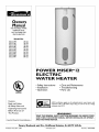
FOR POTABLEWATER
HEATING ONLY
NOT SUITABLE FOR
SPACEHEATING
Model
No.
153.321340
153.321341
153.321440
153.321441
153.321540
153.321541
153.321640
153.321641
153.321840
153.321841
30
30
40
40
50
50
66
66
80
80
Gal.
Gal.
Gal.
Gal.
Gal.
Gal.
Gal.
Gal.
Gal.
Gal.
POWER
ELECTRIC
WATER
• Safety Instructions
• Installation
• Operation
MISER
TM12
HEATER
• Care and Maintenance
• Troubleshooting
• Parts List
LISTED
Caution:
Read and Follow
All Safety Rules and
GAMA certification applies to a[[ residential electric water heaters with
capacities of 20 to 120 Gallons. Input rating of 12 Kw or lessat a voltage
no greater than 250 _L
Operating Instructions
Before First Use of
This Product.
_WARNING
Savethis Manual for Future Reference.
Sears, Roebuck
Printed in the U.S.A. 1203
READ THE GENERAL SAFETY SECTION BEGINNING ON INSIDE COVER
AND THEN THIS ENTIRE HANUAL BEFORE INSTALLING OR OPERATING THIS WATER HEATER.
and Co., Hoffman
www.sears.com
Estates,
IL 60179
U.S.A.
Part No.
184730-O00
Safety Precautions
_kWARNING
.
[
HAZARD OF ELECTRICAL SHOCK! Before removing any
accesspanelsor sorvlciag the water heater, make sure the
electricalsupply to the water heater isturned ='OFF", Failure[
to do this could result in DEATH, SERIOUS BODILY INJURY,
OR PROPERTYDAMAGE.
_,WARNING
.
.
I
Imp_per ;ast_,llatlon,
adiustnnem,
alteration, sarvmce
or mamnteI
nanceeancauseDEATH,SERIOUSBODILYINJURY,,
OR PROP-I
ERTY DAMAGE,Referto this n_nu_l for assistance
or consult
yourlocalSearsServlceCedar for further informatlon,
_kWARNING
HOTTERWATERCAN SCALD:Water heatersare intendedto
=reducehotvratecWaterheatedto a tempersturewhichwillsotisfy spareheating,clotheswmhlag,d!_ washing,
and othersanldzing
needscanscaldand permanentlyinjureyouuponcontact.Some
peoplearemore Iil_lyto be permanently
injuredbyhotwaterthan
others.Theseincludethe elderly,children,the infirm,or physicak
lyimenteJly
handicapped.
If anyoneusinghot water in yourhome
fits intooneofthesegroupsor if t_re isa localcodeor state la_v
requlHnga certaintemperature water at the hotwater _ then
_u musttal_ specialprecaotion_In additionto usingt_ lowest
_essible
temperaturesettingthat satisfiesyourhot water needs,a
meanssuchasa mixingvalve,shallbe usedat the hot water taps
usedbyt_so peopleor at thewaterheater.Mixingvalvesareavelk
able at plumbingsupplyor hand,rarestores.Followmanufacturers
instructions
for insteJladon
ofthevalves.Beforechanging
thefactory so_ng on the thermostat,readthe "TemperatureRegulation"
sectionin this manual.
_kWARNING
At the time of manudacture
this water heaterwasprovidedwith
a combination_mperatere-pmssures reliofveivecertiEadbya
nat;onally recoge;zed
testingbboratery that maintains peHod;c
inspect;onOFproductionof listedequ;pment or materials,as
meot'mgthe requirementsfor ReliefValvesand Autemudc Gas
ShutoffDevicesfor Hot Water SupplySystems,_lndthe current
editionef ANSI 7.21,22. CSA 4,4and the coderequlremer_ ef
ASME, If replasced,
the valve must meet the requirementsOF
localcodes,but not lessthin a €omblnotlontemperature and
_ressurerellef valve certiEedas meetingthe requirements for
ReliefValvesand AutomaticGasShut!offDevlcesfor Hot Wa_r
SupplySystems,ANSI Z21,22 • CSA 4,4 bya nationaily recognized te_tlng laboratorythat maintainsperlodlc iespection OF
_reductfenef listedequipmemor materials,
The valvemust be markedwlth a maximum sot pressurenot
to exceedthe marked hydrostaticworking pressure of the
water heater (150 Ibs,p,_L) and a dischargecapacitynot less
than the water heater inputrate us shmvnon the model rating
plate, (Electric heaters - watts dividedby 1000 x 3412 equal
BTUfHnrate,)
Yourlocaljurisdicdonai
a_Cd*orlty,
whilemandating the useef a
temperatureq_ressurerelief valvecomplylngwith ANSI Z21.22o
CSA 4,4 and ASME,may requirea valvemodeldiffere_ from
the one fumlshed wi_ the water heater,
Compliance with such localrequirememsmust be s_tisfed by
the insteJler or end user ef the water heaterwith a locally prescribed tempera_re.pressure
reliof v_ installedin the designated openingin the water heater in pla_e of the factoryfurnlshedvalve.
Forsafeoperationofthe wa_r heater,the relief valvemust not
be removedfrom i_ deslgrBtedopeningor plugged.
The temperatere-pressurerellef valvemust be iest_lled directly
into the ftting of the water heater designatedfor the teller
valve. Pesidonthe valve downwardand providetublng so that
any d(s_hargewill exit onlywithin6 inchesabove,or at any dis_ancebelowthe structuralI]oor. Be certainthat no €orda_tis
madewith any liveelec_rlcalpart. The discharge
openingmust
not be blockedor reduced in size under any circumstances,
Excess'rye
length,ever 30 feet, or useof more thanfour elbows
can causereslzlctlon and reducethe dischargecap_ity of the
valve,
No valve or other obstructionisto be pla_edbetweenthe relief
valve and the _nk, Do not connecttubingdirectlyto discharge
drainunlessa 6 air gapisprovided.To preventbodilyinjury,hazard to llfe,or propertydamage,the rellef velve must be allowed
to discharge
water in quantitiesshouldcircumstances
demand,If
the discharge
pipeis not connectedto a drainor other suitable
means,the water flowmaycausepropertydamage,
The DischargePipe;
Must not be smallerin sizethan the outlet pipesize of the
valve,or hareanyreduclng€ouplln_s
or other restdctiom.
Mustnot be pluggedor blocl_d.
Mustbe ef mate_al listedfor hot waterdlstzlbotlon,
Mustbe iest_lled soasto allow completedralnageof beth the
temperature-pressurerellof valve, and the dischargepipe,
Musttermlnate atanadequatedr_n.
Mustnot hareanyvalvebetweenthe reliefvaiveand tenL
_kWARNING
WATER HEATERS EQUIPPED FOR ONE _LTAGE ONLY: This
water heater is equipped for one type voltage only. Check the
rating plate near the bottom accesspanel for the correct voltage. DO NOT use thls water heater with any voltage other than
the one shown on the model rating plate, Failure to use the correct voltage can cause problems which can result in DEATH,
SERIOUS BODILY INJURY,,OR PROPERTY DAMAGE. If you
hare any questionsor deub= consultyour electric company,
_kWARNING
INSULATING JACKETS:When installingan external water
heater ;nsulationjacl_t on anelectricwater heater:
a, DO NOT coverthe temperature-pressurerellef valve.
b. DO NOT put insulation over the accesscovers or any
_vCCeSS _e_$.
€. DO NOT coveror remove operatingimtrectlons, and safety related wanning labelsand materials affgod to the water
heater,
d. DO obtain now w_nnlngand instructionlabelsfrom Sears
for placement on the jacl_t directlyover the existinglabels.
I
._,WARNING
.
Do not usethis apphance if any part of mthas been under [
water. An electrical short or malfunction could occur. The
water heater shoud be repaced.
_k CAUTION
WATER HEATERS EVENTUALLY LEAK; Installation of the
water heater must be _ccompllshed in such a manner that if
the t_nl_ or any connections should leak, the flow of water
will not cause damage to the structure. For thls reason, it is
not advisable to instell the water heater in an attic or upper
floor. When such locations cannot be avolded, a suitable
drain pan should be in.lied
under the water heater. Drain
pans are available at your Ioeal Sears Store. Such a dra;n pan
must be piped to an adequate drain,
2
Table
of Contents
Safety Precautions .....................................................................................................
,2
Table of Contents
...................................................................................................................
,3
Introduction .........................................................................................................
,4
Product Specifications .........................................................................................
,4
MatcrMs
Needcd .....................................................................................................................................................................
,5
Basic Tools ...............................................................................................................................................................................
,5
Installation
Instructions
.................................................................................................
6.]5
Rcmo_4ng thc Old \_ater Heatcr .............................................................................................................................................
I_acts to Consider About the Location .....................................................................................................................................
I_acts to Considcr About the Convertible Lowcr Elcmcnt .........................................................................................................
\_ater Piping ............................................................................................................................................................................
T&P Valvc and Pipe Insulation .............................................................................................................................................
Temperatttre- Prcssurc Roller Valve ............................................................................................................................................
Filling thc _'atcr Hcatcr ..........................................................................................................................................................
Converting the Lowcr FJcmcnt .........................................................................................................................................
\g_ring Diagrams ....................................................................................................................................................................
\g_ring ....................................................................................................................................................................................
Installation Chccklist ..............................................................................................................................................................
Thermostats
............................................................................................................................................................................
Thermostat Settings ................................................................................................................................................................
Upper and Lower Thermostat Adjustment ..............................................................................................................................
Tcmpcramrc-Prcssurc
RolicfValve Opcration ..........................................................................................................................
Draining .................................................................................................................................................................................
Element Clcaning and R.cplaccmcnt .................................................................................................................................
Anode Rod lnspcction ...........................................................................................................................................................
Drain "_zal_,-c
_'ashcr R.cplaccmcnt ..........................................................................................................................................
Scrvicc ...................................................................................................................................................................................
Thermal Expansion ..............................................................................................................................................................
Strange Sounds ....................................................................................................................................................................
Operational Conditions .....................................................................................................................................................
Smdly \rater ........................................................................................................................................................................
Air in Hot _ter
_aucct's ....................................................................................................................................................
Rumbling Noise, ..................................................................................................................................................................
High Temperature Shut Of_'System .................................................................................................................................
Not Enough or No Hot _;ater .............................................................................................................................................
_;ater is Too Hot .................................................................................................................................................................
Leakage Checkpoints
.............................................................................................................................................................
,6
,,7
2
,8
,8
,9
]0
10. 12
]3
14
]5
16
]6
W
W
W
l 8-20
,20
,20
,20
£]
£ ]
22,23
£2
£2
£2
22,23
£3
£3
£4
Parts Order List.....................................................................................................
2a.3]
Warranty ...............................................................................................................
32
3
Introduction
Thank
Abbreviations
Found In This Instru_.xion
U.L. - Undcrwritcrs Laboratories Inc.
NEC- National Elcctrical Codc
ANSI - Amcrican National Standards Institutc
You forpurchasing
a Scars
watcrhcatcr.
Propcrly {nstallcd and mah_t:fincd, it should glvc you years of
trouble fi'cc scr_4cc, If you shotfld dcddc that you want the ncw
water hcatcr profhsslonally lnstallcd, contact thc local Scars
SctMcc Ccntcr or any Scars stoic. Thcy will arrange for prompt,
quall_T installation by Scars authorb;cd contractors,
Product
MODEL
.NUMBER
153.321340
153.321341
153.321440
153.321441
153,321540
153,321541
153,321640
153,321641
153.321840
153.321841
Manual
Specifications
TANK
CAPACITY DLMFAqSIONSINI_CI-IF_
IN GALLONS DIAMETER HEIGHT
30
19
47
40
20
60_
50
22_
62
66
24
62
80
26
62
RECOVERY RATE
GALS. PER HOUR
@90OE RISE
17,3
25,0
17,3
25,0
17,3
25,0
17,3
25,0
17,3
25,0
ELEME_IT
WATTAGE
AT 240 VOLTS
UPPER LOWER
3800
3800
3800
3800
3800
3800
3800
3800
3800
3800
MINIMUM
WIRE SIZE*
(GAUGE)
3800
5500
3800
5500
3800
5500
3800
5500
3800
5500
12
10
12
10
12
10
12
10
12
10
MAXLMUM FUSE
OR CIRCLrlT
BRFARF_
SIZE(AMPS)
20
30
20
30
20
30
20
30
20
30
*'Wiring slzc bascd on standard 60°C coppcr wirc. If dJstancc from fusc box to watcr hcatcr is morc than 90 ffcct,rcft:r to ?/our local clcctric01codc,
Preparing
for the New
° Rcad thc "Safi:ty Prccautlons" section, pagc 2 of this manual
first and then the cntlrc manu'al carcfiMI); If you don't follow
thc saffc_Trules, thc watcr hcatcr w411not opcratc propcrl): It
could causc DEATH, SERIOUS BODIIX
INJURY
AND/OR PROPERTY DAMAGE.
This manual contains instructions [br the installation, operation, and malntcnancc of this clcctric watcr hcatcr. It also
contains warnings throughout thc manual that you must mad
and bc awarc of, All warnings and all instructions arc esscntial to thc propcr opcratlon of'the watcr hcatcr and your s'afct); Since wc cannot put eyeD'thing on thc first few pages,
RFAD THIS ENTIRE MANUAL BEFORE ATTEMIrlL
ING TO INSTALL OR OPERATE
THE WATER
HFATF.IL
Installation
If"af_cr rcading this manual you havc any questions or do *tot
undcrsvand any portion of thc instructions, ca.llScars Scr_4cc
Ccntcr,
Carcfully plan thc placc whcrc you arc going to put thc watcr
hcatcr, Corrcct clcctrical _4ring and conncctions arc vcry
lmporvant inprcvcotlng dcath from possible clcctrlcal shock
and fires,
Faaunlnc the location to cnsurc the watcr hcatar complies with
thc "Fac_s to Consider About thc Location" scction,
For Callfbmia installation this watcr hcatcr mt_st bc braced,
anchorcd, or strappcd to avoid Jailing or mo_4ng dt_rlng an
carthquakc, Scc instructions for corrcct installation proccdurcs. Instructions may bc obtained from yot_r local dcdcr,
wholcsalcr, public utilities or Callfo!_nla officc of the Svatc
Archltcct, 400 P Street, Sacramcnto, CA 958714,
• The insvailation must con_rm with the instructions in this
manual; clcctrlc company rMcs; and Local Codes, or in thc
abscocc of"Local Co&s, with the currcnt cdJtlon of the NEC
• National Elcctrlcal Code, NFPA 70, This publication is
awallablc from your local govcrnmcnt or public library or
electric company or by writing Underwriters Laboratories
Inc,, 333 Pfingstco Road, Northbrook, IL 60062,
Massacht_sctts Code requires this water hcatcr to bc installed
3n accordancc wtth Massachusetts 248+GMR _,00: Statc
Plt_mbmg Codc and _a_8.CMR 5,00,
4
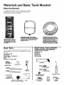
Materials
and Basic Tools Needed
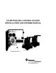
Materials Needed
To simpli_T thc i*tstallation Scars has availablc thc i*tstallatio*t
parts shovcx_bclow. You may,or may,r_otnccd all ofthcsc matcrb
als dcpcndJng on ,,Tourtypc oi:'installatior_.
WATER HEATER INSTALLATION KIT WITH FLEXIBLE
CONNECTORS
FOR 3t4' OR
1t2_ THREADED OR COPPER
PLUMBING
Basic Tools
You may or may rtot nccd all of these tools, dcpcndJ*tg on your
typc of ir_svallation.
Scars s_aor¢,
Thcsc
tools
DRAIN PANS AVAILABLE
IN 20"
DIAHETER FOR WATER HEATERS
HAVING A DIAHETER
18" OR LESS,
24" DIAMETER FOR WATER
HEATERS HAVING A DIAHETER 22"
OR LESS AND AVAILABLE IN 28"
DIAHETER FOR WATER HEATERS
HAVING A DIAHETER 25" OR LESS
EXPANSION
TANKS FOR THERMAL
EXPANSION
CONDITIONS
AVAILABLE
IN 2 GALLON AND 5 GALLON CAPACITY
THROUGH
LOCAL SEARS STORE OR
SERVICE CENTER
can
bc pttrdlascd
at your
Pipe Wrench (2)
Screwdriver
6 Foot; Tape or Folding Rule
Garden Hose
Drill
Pipe Dope or Teflon Tape
local
ADDITIONAL
TOOLS NEEDED
WHEN SWEAT SOLDERING
Tubing
Cubers
Propane
Torch
Soft; Solder
Solder
Flux
or
Hacksaw
Emery
Wire
Cloth
Brushes
6 FOOT TAPE
GARDEN
HOSE
3t4" WIRE BRUSH
SLOT-HEAD
PHILLIPS
SCRE',H DRIVER
PIPE
WRENCH
1t2" WIRE BRUSH
SCREWDRIVER
_;_
PROPANE
TORCH
ROLL OF LEAD FREE
SOFT SOLDER
PIPE DOPE
(SQUEEZE
TUBE)
ROLL OF TEFLON
(Use
only on water
TAPE
connections)
DRILL
ROLL OF EMERY
CLOTH
SOLDER
FLUX
TUBING
CUTTER
Installation
Instructions
Removing the Old Water
Heater
OTum
a,
"OFF" electrical supply to the water hcatcr,
J
q
If you havc coppcr piping to thc watcr
hcatcr, the t_-o coppcr water pipes can bc
cut with a hacksaw appro_matcly 4" a_ay
from whcrc they connect to the watcr
hcatcr, This will avoid cutting offthc pipes
too short, Addkional cuts can bc madc
later if"necessary, Disconncct the tcmpcraturc-prcssurc rclicf valvc drain linc, Whcn
the watcr hcatcr is draincd, dJsconncct the
hose from the dmln valvc. Closc thc drain
valve, The water heater is now completdv
dJsconncctcd and ready to bc removed,
"
Turn _OFF" the water supply to the
water heatcr at thc _atcr shutoffvalvc or
water
meter,
b, [f you have galvanizcd pipc to the watcr
hcatcr, Iooscn thc t_-o galvanizcd pipcs
with a pipc wrcnch at thc union in cach
Iinc. Also dJsconncct thc piping rcmaining
to the water heater, Thcsc picccs should bc
saved since they may bc nccdcd when
reconnecting
the new water heater,
Disconnect the tcmpcraturc-prcssurc rclicf
walvc drain linc. Whcn the watcr hcatcr ls
dralncd, dlsconncct thc hosc from the
drain valvc, Closc the drain valvc. The
water heatcr ls now complctdy dJsconnccv
cd and ready to bc removed,
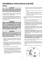
OAttach
a hose to the _ater heater drain
valve and put the other end in a floor
&'ain or outdoors, Open the water heater
drain yah-c, Opcn a nearby hot water
_:aucct which will rclicvc pressure in the
_atcr heater and speed draining.
L
AWA N,N
I
The water passingout of the drain valve may be extreme. I
ly hot, To avoid being scalded, make sure all connections
are t_ght and that the water flow _sd_rected away from
any person,
Check
make sure the clcctric'al supply is
tumcd OFF to thc watcr hcatcr, Thcn discomlcct
thc clcctrical supply conncction i:_om thc water
hcatcr jtmction box,
_O
A CAUTION
J
I
M_neralbuildupor sediment m_rt haveaccumulated •inthe
old water heater• This causes the water heater to be [
much heavier than normal and th_sresidue, _f sp_lledout,
could causestaining,
6
Installation
Instructions
(cont'd)
Facts to Consider About the
Location
Facts to Consider About The
Convertible Lower Element
You should carcfully choosc an indoor location for thc ncw
watcr hcascr, bccausc thc placcmcnt is a vcry important considcrasion for thc s',ffcv,"of thc occupants in thc building and for
thc most cconomic'£1 usc of thc applbmcc, This _atcr hcascr is
not intcndcd for outdoor installation.
Thc Uppcr Elcmcnt (if a doublc clcmcnt modcl} is a convcntional 3800 watt clcmcnt which only opcratcs at its ratcd
wawagc on 240 volts, (Scc rating plasc on watcr hcascr},
Thc _x_wcrElcmcnt of thc _atcr hcascr can bc convcrtcd from
opcmtion at 3800 _atts to 5500 _atts on a 240 volt _Tstcm,
_'hcthcr
rcpladng
an old watcr hcatcr or putting thc watcr
hcascr in a nc,,_- location, thc fi_llo,_4ng critic,a1 points must bc
obscrvcd,
Rcad and follow _atcr hcascr _asnings and instructions. If"aftcr
t_cading thcsc instructions in this mtmu'al if you do not undcrstand any portion, call Scars Scr_4ccCcntcr. "
• Thc location sclcctcd should bc indoors as dosc to and as
ccntralizcd with thc watcr piping systcm as possiblc, This
watcr hcatcr, as wcll as all wascr hcatcrs, will cvcnn_lly Icak,
Do not install without adcquasc drainagc provisions whcrc
watcr flow will causc damagc.
_,WARNING
Before making the conversion to 5500 watts, check the
(I) power supply...must be 240 volts, (2) wlrlng...10 gauge
AWG, Type TW, 60'C or equivalent,
and (3) Circuit
breakers or fas_ng...capable of 30 amp leading. Also, the
_astellotlon must conform wlth th_s manual, local codes
and electric otil_ty rules, Failure to comply can result in
DEATH, SERIOUS
BODILY INJURY, OR PROPERTY
DAMAGE.
_k CAUTION
WATER HEATERS EVENTUALLY LEAK: Instellat_on of
the water heater must be accomplishedin sucha manner
that if the tank or any connectlonsshouldleak, the flow of
water will not cause damage to the structure. For th;s
reason, it ;s not advisable to install the water heater ;n an
attic or upper floor. When such locationscannot be avo;ded, a su;table dra;n pan should be installed under the
water heater. Drain pans are available at your local Sears
stores. Such a drain pan must be piped to an adequate
draln.
CAUTION
INSTALLATION
IN RESIDENTIAL GARAGES: The I
water heater must be located andtor protected so _t _sI
not subjectto phys_cai
damage by a reaving vehicle.
I
* Thc location sclcction must prm4dc adcquatc clcaranccs for
scrvidng and propcr opcrasion ofthc _atcr hcatcr.
NOTE: _hether
or not the dement
conversion is made the
mode[ rating plate m_st be tnagked, Using a hard point ink
pen_ check the appropriate
block within the model rating
platP_ which is located adjacent to the lower access panel,
7
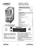
Installation
Water
Instructions
(cont'd)
Piping
Installation completed
Installation Kit
*_WARNING
HOTTER WATER CAN SCALD: Water heaters are
_ntended to producehot water. Water heated to a temperature whichwill satisfy spaceheating, clotheswashing,dish
washing,and other sanitizingneeds can scald and permanentlyiniure you uponcontact. Some peopleare more I;l_ly to be permanently injured by hot water than others.
These includethe elderly, ch;Idren,the infirm, or physically/mantally handicapped.If anyone usinghot water in your
home f_s into one of these groupsor it there isa localcode
or stete law requMng a certe_lntemperature water at the
hot water tap, then you must _
specialprecautlons.In
addit;on to using the lowest possibletemperature setting
that sat;diesyour hot water needs,a means such as a mix.
;ng valve, shall be usedat the hot water taps used bythese
people or at the water heater. Mixingvalvesare ava'llableat
plunnblngsupplyor hardware stores. Followmanufacturers
;nstrectlons for instellatlon of the valves. Before changing
the factory setting on the thermostat,
read the
"Temperature Regulation"section in th;s manual.
HOT WATE R_A
OUTLET
!
using
FLEXIBLE
WATER
CONNECTORS
SHUT-OFF
VALVE
HOT OUTLET
TO HOUSE
THREADED TO
SWEAT COUPLING
314" THR_,DED
_
NIPPLE
_
_
_
3!4" THREADED
_
NIPPLE
COLD WATER
/
TEHPERATUREPRESSURE
RELIEF VALVE
--
DISCHARGE PIPE
(Do not cap or plug)
INLET
TEHPERED
WATER OUTL
_L_-)!
_
_-Ta_7
*MIXING VALVE
A
]_)
COLD WATER
T
•
INLET ON
FROM HOT
'WATER HEATER
WATER OUTLET
ON WATER HEATER
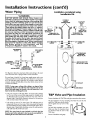
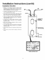
T_e ilh_srvarionshows the attachment of the water piping to the water
heater.The water heater _sequipped_4th !_#water connections.
If a w_rer heater _sir_-t_ kl a de_cd water supply sT.
stem; suc_ as one
_v_ng a back-flowpreventer,check_alve,w_rcrmeterwith a checkv_v_c,
cxc,in the cold",cater
sr.ppL_me;_._shall be providedto control thermg
_pa_ion. Contact the localutility or Iocg S_ ServiceCenter on how
to control this galation.
6_ AIR GAP
NO'rE_If oslng copper fadslng,solder fathlngto an adapter before
attaching the adapter to the cold _ater inlet connection. Do not sob
der the cold _at_ sopply llne dice_dyto the cold wat_ inlet, It will
luL_ta
the dip tube and damagethe tank.
* Ix_okat _e top coverof the water h_ter. The water ot_rletis marked
hot. Pt_t_¢o or three turns of tenon _apcaround t_e threaded end of
tl_e threadcd-to-sweat cot@ing and arotmd both ends of thc _4"
thr_dcd nipple.UsLngflcxibLcconnectors,connect _e hot water pLpe
to the hot water outlexof the water heater.
• Look at the top cover of t_e water heater, The cold water inlet _s
marked cold,Put two or th_c turns of teflon rapearound the thro_dcd
end of the thr_dcd-to-s'weatcouplirg and arotmdboth ends of the _"
thr_dcd nipple. Usingflexibleconnectors,connectthe coldwater pLpe
to the coldwater inletof the water heater.
NOTE_Your'w_,tor
heater is s_per insulated to minimize heat loss
from the tank, Forther reductionin lu_ loss can be acxomplisbed by
insulating the hot wagerlines firomthe wat_ heater_
FLOOR
DRAIN
T&P Valve and Pipe Insulation
Rcroovc insu_tion
for T&P VaLve and pipe connections from carton.
Fit pipe insulation over i:hc incoming co]d water ]inc and the hot
wa_er [inc. Make s_re tha_ the insuLa-
tion is against cl_ccop cover of i:he
h_atcr.
N_ T&P VaLveins_daciono_rcrvalve.
M'_c sure cleat dsc insulation does
not interfere with the Lever of the
T&P v_,rc.
Sc_ct_rc
_L im_uLacionusing tape.
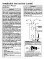
Installation
Instructions
Temperatu re- Pressure
Relief Valve
(cont'd)
_t, WARNING
The temperature-pressure reNef valve must be manually
operated at least once a year, Caution should be taken to
ensure that (I) no one is _n front of or around the outlet
of the temperatero.pressuro relief valve d_schargeline,
and (2) the water manually dischargedwill not cause any
bed_ly _niury or property damage becausethe water may
be extremely hot.
If after manually operating the valve, it failsto completely
reset and continues to release water, immediately, close
the cold water inlet to the water heater, follow the dra_n_n.ginstructions, and replace the temperature.pressure
rehef valvew=th a new one,
_I, WARNING
At the time of manufacture th;swater heater was prev;ded
with a combinationtemperaturo-pressurosrelief valve certified by a nationally recognized testing laboratory that
maintains periodic _nspectlon of production of listedequipment or nnateHais,as meeting the requ_remantsfor Relief
Valvesand Automatic Gas Shutoff Devicesfor Hot Water
Supply Systems, and the current ed_tlonof ANSI Z21.22 •
CSA 4.4 and the code requirements of ASME, If replaced,
the valve must meet the requirements of local codes,but
not less than a €omb;nation temperature and pressure
relief valve ce_t;fiedas meet;ng the requ;romentsfor Relief
Valvesand Automatic Gas Shutoff Devicesfor Hot Water
Supply Systems,ANSI Z21.22 • CSA 4.4 by a natlonaily recogn;zedtest;ng laboratory that ma;nt_Jns peried;€ iespect;on of productlon of listedequipment or materials.
The valve must be marked wlth a maximum set pressure
not to exceed the nna_kedhydrostati€worklng pressureof
the water heater (150 Ibsdsq,_n,)and a d_sch_mge
Cal_€_ty
not lessthan the water heater _nput rate as shownon the
model rating plate. (Electric heaters, watts divided by
1000x 3412 equal BTUIHr, rote,)
Your local jurisdictionala_tberity, while mandatingthe use
of a temperature-pressure relief valvecomplyingwith ANSI
Z21,22 • CSA 4,4 and ASME, may reqmre a valvemodel different from the one furnishedwith the water heater.
Compl;ancewith such local requirements must be satlsfied
by the installer or end user of the water heater w;th a
locally prescribed temperature.pressure
relief valve
;nstelled ;n the deslgnatedopening in the water heater ;n
)laceof the f_tory furnishedvalve,
For safe operation of the water heater,the relief valve must
not be removed from it'sdesignatedopeningor plugged,
The temperaturo.pressuro rel;ef valve must be installed
directly ;nte the fitt;ng of the water heater des;gnatedfor
the relief valve. Pos_tlonthe valve downward and provMe
tubing so that any d;sch_urge
w;ll exit only with;n 6 inches
above,or at anydistencebelow the struttu_d floor, Be certeln that no contact is made with any I_veelectrical
The d_sch_mge
opening must not be blocked or reduced _n
s_ze under any cireumstances, Excessivelength, over 30
feet, or useof more than four elbowscan causerestriction
and reducethe d_sch_urge
cap_city of the valve.
No valve or other obsttuct]on_sto be placedbetween the
relief valveand the tanl_ D_onot connecttubing d_rocdyto
dischargedra_n unlessa 6 a_r gap _sprovided,To prevent
bed_ly_njury, h_urd to llfe, or property d_umage,the relief
valve must be allowed to discharge water _n quantities
should €_rcunnst_ncesdemand. If the dischargep_peis not
connected to a drain or other su_teble means, the water
flow may causeproperty damage.
The D_sch_urge
Pipe:
• Must not be smaller in s_zethan the outlet pipe size of
the valve, or have any reducing couplings or other
restHttions,
• Must not be pluggedor blocked,
• Must be of nnateHaiI_stedfor hot water distribution,
• Must be installed so as to allow complete drainage of
both the temperature-pressure relief valve, and the d_schargepipe,
• Must terminate at an adequate dra_n,
• Must not have any valve between the relTefvalve and
tenl_
HOT
COLD
HOT
PRESSURE
RELIEF VALVE
(Do noc cap or plug)
0
FLOOR DRAIN
WARNING
"RELIEF
6_ AIR GAP
•
VALVE OPENING"
J_,_KE7
T&PBELIEF
VALVE PR(._E
UUS_ E_TEND
[NTOTANK
i
_IZMPE_TUREIPBE_URE
REUEFVALVE
NIPPLE
_
9
hl_l
h,_di[l_ - "T_mp_l_l_-Pr_r_
Ft_li_fV_I¢,__ _l i[1_'_11_Ii__M I_i_l_tl_
¢_R_[_
Installation
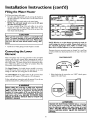
Filling the Water
Instructions
(cont'd)
Heater
To fill the water heater Mth water:
•
Close the water heater drain valve by mining the handle to
the right (clock'wise). The drain valvc is on thc lowcr front of.
the water heater.
° Opcn thc cold wascr supply valvc to thc wascr hcatcr.
NOTE: The cold water sopply valve mast be left open
when the water heater is in a_¢_
• To insttrc complctc filling of thc va.nk, allow air to cxlt by
opcning thc ncarcst hot watcr fZaucct. Allow watcr to run
tmtil a constant flow is obvaincd. This will Ict air out ofthc
watcr hcatcr and thc piping.
•
ELECTRIC
n _sspo_Nc_
Pa,gqDi_l
THIF_ tr--_TER
r,_'$
P&.
WATER
_
EK_E k NUMBER
HEATER
C_PA_
JTY
!
FACTORY EQUIPPED WITH
ECO
IN_rALLF_
EEE_IAL N_
I
U,_ GAL. ::
•
.
...
.
L_m_R
CAUTION
Never use this water heater unless _t _scompletely full of I
water, To prevent damage to the tank and heating ele- I
ment, the tank must be filled with water. Water must I
flow from
power.
*
the hot water
faucet
before turning
"ON"
NOTE: Whether or _ot the element cmxversion is made the
model rating pla*e most be marked, Using a hard point ink
petx, check the appropriate block withitx the model rating
plate, which is located adjacent to the lower access panel
Check ,all new watcr piping _r lcaks, Repair as needed,
Converting
Element
Ncccssat T clement conversion parts arc located in a small bag
containcd MthJn thc clcctrical junction box on top of" thc watcr
hcatcr.
the Lower
CONVERSION
These instructions only cover the convcrdon of the convertible
dcmcnt, mad this entire manual bcforc attcmpting to install or
opcratc thc watcr hcatcr, Thc wascr hcatcr is J:actoW sct to opcrarc at 3800 watts, The lower clement can be convcrtcd to operasc at 5500 watts. Rcfi:r to thc "Facts to Consldcr About thc
Convcrtlblc Lower Elcmcnt" scction,
Thc Upper Elemant, (ii:'a doublc clcmcnt modal) is a convcntional 3800 watt clement which only operates at its rated
wawagc on 240 volts, (Scc rating plasc on water heascr/,
PARTS
BUSS BAR
The Lower Element of the water heater can bc converted from
operation at 3800 watts to 5500 watts on a 240 volt _'ystcm,
1, Bcforc bcginnlng the convcrsion turn "OFF" clcctric power
supply to thc wascr hcatcr,
[i:'al_cr reading these instructions and this manual, ii:you do not
undcrsvand any portion, call Sears Scrvicc Center.
AWARNING
Before making the conversion to 5500 watts, check the
(I) power supply..must be 240 volts, (2) wiring...10 gauge
AWG, Type TW, 60'C or equivalent, and (3) Circuit
breakers or fus_ng..capableof 30 amp loading. Also, the
_nstallat_on must conform w_th th_s Manual, local codes
and electric utiNty rules. FAILURE TO COMPLY CAN
RESULT IN DEATH_ SERIOUS BODILY INJURY OR
PROPERTY DAMAGE.
AWARNING
HAZARD OF ELECTRICAL
SHOCKI Before removing
any access panels or servlcing the water heater, make
sure the electrical supply to the water heater is turned
"OFF".
FAILURE TO DO THIS COULD
RESULT IN
DEATH_ SERIOUS
BODILY INJURY, OR PROPERTY
DAMAGE.
]0
Installation
Instructions
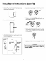
2, Thc convcrtiblc clcmcnt is Iocatcd bcMnd thc Iowcr acccss
paacl of thc _atcr hcatcr, Rcmovc thc t_-o scrcw_ssccur_ng
thc acccss paacL and rcmovc paacl,
(cont'd)
5. Rcmovc thc scr_vs from tcrminal 2 o17thc clcmcnt, and movc
thc Ioopcd cnd ofthc wirc asidc,
6. Thc buss bar is labclcd 5500 W. Placc thc buss bar ovcr
tcrm{nals 2 and 3 with the 5500 W vis{blc, rnsv_all the cxtra
scrcw provided into tcrm{nal 3.
3. Rcmovc thc insulation block and pad,
I
I
7. Thc wbc rcmovcd fi'om tcrm_nal 2 has a loopcd cnd, lt must
rcma_n loopcd and now bc placcd (as shown) on top of thc
buss bar, ovcr thc opcn_ng of tcrm_nal 2, and sccurcd udng
thc rcma{ning scrcw,
4. Lower Elemen_ l.{f_ out thc tab as shown to undip thc tcrminal covcr from thc thcrmostat, Tbc tcrminal covcr can bc
rcmovcd I_}omthc thcrmosmt,
Lli_. ou_ tab to u_¢Tl_
I_-_ -_
8. T{ghtcn
I 0
j
,
:
2 and
3 to cnsurc
propcr
clcctrical
_WARNING
,
I
Failure to t_ght_n terminal screwscan cause a fire which
can result _n DEATH, SERIOUS BODILY INJURY, OR
PROPERTY DAMAGE.
TIq E RblOSTAT
/BRACKET
_K_
tcrminals
_ODnCCISiOn,
PI-ASTIC TA_S ON
BOTH _IDES OF
/ TEFe3_INAL COVER
14OLD IT IN
FLACE.
TANK
ELEMENT
7171
Installation
Instructions
(cont'd)
Converting the Lower
Element (cont'd)
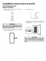
9.
Rcplacc tcrmin'al covcr on tllc thcrmosvat,
notch is in placc ovcr thc vab.
making
] 1. Rcplacc thc acccss pancl.
surc thc
_gga
712. Complctc wiring to thc _atcr hcatcr, or if complctcd, turn
"ON" clcctrlc powcr to thc _atcr hcatcr 'aJrtcrt211lng thc
tank w4th watcr.
_WARNING
•
Make sure the thermostat is flush against the tank, the
term_n_Jcover is in place, and the _nsulat_on _sreplaced.
F_Jlueeto do so can result _n DEATH, SERIOUS BODILY
INJURY,OR PROPERTY DAMAGE.
1
10. Rcplacc thc insulation block and pad so that it complctcly
covcrs thc thcrmosvat and dcmcnt,
CAUTION
Never use this water heater unless_t _scompletely full of ]
water. To prevent damage to the tank and heating ele- ]
ment, the tank must be filled with water. Water must I
flow from the hot water faucet before turning "ON"
power,
71
2
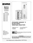
Installation
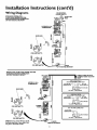
Wiring
Instructions
Diagrams
(cont'd)
TO ELECTRIC
PO',HE R SUPPLY
STANDARD WIRING FOR
2 WIRE LEAD WATER HEATERS
NON-SIHULTANEOUS
OPERATION
240 VOLT DOUBLE ELEMENT
B_C_r_C_JUo_CT'°N
UPPER
E.C.O.
_ r_D_J,E
THERHOSTAT
_USSBA,_o_7_
\
'\
_I
E
FOR 5500 WA'i-I'S
FOR.0WATTS
_____j--___J.EAT,L_._:.ENT
WIRING FOR 3 WIRE LEAD WATER
NON-SIMULTANEOUS
OPERATION
240 VOLT DOUBLE E/EHENT
HEATERS
THREE TYPES OF FIELD
CONNECTIONS
YOU HAY
HAVE
TIME CLOCK
OPERATES BOTTOM
UPPER E.C.O. &
THERHOSTAT
TO ELECTRIC
POWIERSUFFLY
_
SWITCH
ELEMENT
ONLY
L.7. _
TO TIME
LT
L2 L.7. CLOCKSWITCH
JUNCTION
BUSSBAR\
\
YELLO_VL@BI_C
",,
\
"OFF PEAK" METER
OPERATES BOTTOM ELEMENT
TOELECTRIC
POWER SUPPLY
_
LI
L2LIL2-_'
{'
_
__
FOR S$0O WAI-I'S
_
ONLY
TO"OFF
PEAK s_METER
_UNCTION
TO ELECTRIC
FOWER SUPPLY
WIRE CONNECTION
LI
L2
JUNCTION
3800 W
S
*NOTE:
Some Lower Hi-Temp
SwTtches rn_y Eave 4 terminals,
only d_e 2 _ermTn_ls on left.
_
Limit
Use
BOX
,9,
ELENEN
L,sO_TAETR
FOR TWO
O
BOX
K
LOWER
HEATING ELEMENT
l]3
BOX
Installation
Instructions
(cont'd)
Wiring
A CAUTION
C, Flexiblc mcval conduit or flexiblc mcvallic robing shall bc
pcrmktcd _r groundhog if",dl thc following conditions arc
.
Never use this water heater unless it Is completely full of J
water. To prevent damage to the tank and heat_ng ele- J
nnent, the tank must be filled with water. Water must
flow from the hot water faucet before turning on power.
tDet:
], Thc Icngth in any ground return path docs not cxcccd
6 fcct,
2, Thc circuk conductors convAncd thcmin arc protectcd
by ovcrcurrcnt dc_4ccsrased at 20 ampcrcs or less,
You must providc all _4ring of thc propcr size outsidc of thc
wascr hcatcr, You must obcy local codcs and clcctric company
rcqtfircmcnts when you install this _@ing.
3, Thc conduit or tubing
approvcd _r grounding.
rfyou arc not _amiliar w4th clcct£c codcs and pracficcs or if you
have an), doubt, cvcn thc slightcst doubt, in your ab[li_Tto conncct thc _4ring to this wascr hcatcr, obtain thc scrv[cc of a compctcnt clcctrldan. Contact yottr Scars s',dcspcrsonto arrangc for
a profcssional clcctridan.
is tcrminatcd
in fittings
For complctc grounding dcta]ls and all allowable exceptions
rcfizr to the current edition of the National Electrical Code
NFPA 70.
4,
AWARNING
A svandard _' con&fit opcning has bccn made in the water
hcater jtmction box _r the conduit conncction.
5. _TJring Diagrams
(Scc Wiring Diagrams Scction) have bccn
supplied showing the two most common types of connections bctwccn the water hcatcr and thc power supply, You can
easily see which type connection you have by remo_4ng the
junction box covcr on top ofthc watcr hcatcr,
WATER HEATERS EQUIPPED FOR ONE VOLTAGE
ONLY: This water heater is equlpped for one type voltage
only. Checkthe rating plate near the bottom accesspanel
for the correct voltage. DO NOT use thls water heater
with any voltage other than the one shown on the model
rating plate. Failure to use the correct voltage can cause
problems which can result in DEATH, SERIOUS BODILY
INJURY,OR PROPERTY DAMAGE. If you have any questlons or doubts consultyour electrlc company.
A. Two W'me Connection Diagran*s+ is thc most common
requiring you to simply connect red to rcd, black to black,
and the grotmd w4rc to thc grccn ground scrcw in the jtmc+
tion box ofthc watcr hcatcr,
B+ Three "_7"tre Connection
Diagram+ is uscd whcn you arc
connccting
thc watcr hcatcr to powcr a supply that has a
"Time Clock" or "Off" Pc'ak" Mctcr, To make these connections rcfcr to block ] or 2 in this _4ring diagram _r thc typc
of _Tstcm you havc,
A CAUTION
If wirlng from your fuse box or clrcuit breaker box was
aluminum for your old water heater, replace it wlth copper wlre. If you wish to reuse the exlsting aluminum wire,
havethe connection at the water heater made by a competent electrician. Contact your Sears salesperson to
arrange fora prefesslonalelectrician.
NOTE:
water
Peak"
power
block
]. Providc a way to casily shut off thc clcctric powcr whcn
working on thc watcr hcatcr, Tiffs could bc with a circuit
brcakcr or fusc block in thc cntrancc box or a scparatc disconnect swkdl,
2. lnsvall and conncct a clrctfit directly from thc main fusc or
circuit breaker box, This circuit must bc the right sb;c and
have its own fuse or drcuk breaker. Refer to the chart in the
"Product Spcdfications"
section fi_r the correct size wbc and
fitsc or circtfit breaker,
If yo. have parcdaased a three wire connection
heater bltt yollt are not on a "Time Clock" or "Off
meter and have a standard
two wire connection
sltpply_ simply follow the connection
diagram
in
3. of the Three Wire Connection Diagram.
6,
Usc wirc nuts and conncct thc power
wircs insidc the wascr hcatcr's jtmction,
7
Thc watcr hcatcr must bc clcctrically
"groundcd"
by thc
installer. A grccn ground screw has bccn provided on the
water hcatcr's junction box, Connect
ground wlrc to this
location.
8. Rcplacc thc _@ing jtmctlon
supply _4ring
covcr using thc scrcw¢ pro_4dcd,
3. [f mcval conduit is uscd fi_rthc grounding conductor:
A, Thc grounding
clcctrodc conductor
shall bc of copper,
aluminum,
or coppcrclad alumintmt. Tbc matcrhl shall
bc ofonc continuous Icngth _dthout a splice or joint.
WIRE
NUTS
/
CONDUIT
B. Rigid mctal conduit, intcrmcdiatc mcval conduit, or clcctrical metallic tubing may• bc used for thc gr0undin g
mcans if conduit or tubing is terminated
in fittings
approvcd for grotmdlng.
-GREEN
GROUND...- /
SCREW
14
to the
Installation
Instructions
(cont'd)
Installation Checklist
° Whcthcr or r_ot thc clcmcr_t convcrsior_ is madc, thc modcl
rati:tg platc must bc markcd. Usi:tg a hard point i:tk pc*t,
chcck thc appropriatc block within thc modd rating platc,
which is Iocatcd adjaccnt to thc Iowcr acccss pancl.
°
HOT
COLD
is thc fiasc or drcuit brcakcr sirsacorrcct as shown in thc chart
in thc "Product Spcdfi'Lcatioas"scctioa?
CONDUIT
° Arc thc wircs from thc circuit brmkcr or fiasc scrv[cc to thc
....
(
watcr hcatcr +s junctmn
box on thc corrcct wire sc,sa,gaugc}
as
shown in thc chart in thc "Product Spccit4cations" scction?
°
rs thc :tcw tcmpcraturc-prcasurc
rclicf valvc propcrly
msvallcd, and ptpcd to an adcqtlatc dram. Scc TcmpcraturcPrcssurc Rclici:Valvc"scction.
°
rs thc _atcr hcatcr complctclv RIIcd with _atcr? Scc "Filling
thc Watcr Hcatcr
tastrucuons
m thc Iasta atto:t
[nstructions"
RELIEF VALVE
scction.
• Will a _atcr lcak damagc anything? Scc "Facts to Considcr
About thc Location" scction,
•
Arc thc co]d and hot watar tines conncctcd to thc _atcr hcatcr
cortvct]y? See _Watar Piping" it_strucciot_s in the "[nsmttation
[t_struc_iot_s
_ sect-ion,
°
ls thcrc adcquatc clcarancc _r ma_ntcnancc around thc watcr
hcatcr?
°
Do you r_ccd to call your clcctric company to chcck your
wiring?
PIPE
(Do not cap or plug)
I
6nAIRGAP
FLOOR
MODEL RATING
_15
PLATE
DRAIN
Service
Temperature
and Adjustment
Regulation
The lower thcrmosvat is J:actot_,Tset at a position which approximates I L0 F IHOT) and Js ai]:B*svablc ti:•a dtfi_crent water temperature is desired, Read ,all warnings in this mantial and on the
water heater be_rc proceeding.
A WARNING
HOTTER
WATER CAN SCALD: Water heaters are
_ntended to produce hot water, Water heated to a tom.
perature which w_ll satisfy space heating, clothes washing,
d_sh washing, and other sanitizing needs can scald and
)ermanently _njure you upon contact, Some people are
more likely to be permanently injured by hot water than
others, These include the elderly, children, the _nfirm, or
physically/mentally
handicapped,
If anyone using hot
water in your home fits _nto one of these groups or _f
there is a local code or state law requiring a ce_m
tom.
)erature water at the hot water tap_ then you must take
special precautlons. In add;tlon to us;ng the lowest poss;ble temperature
sett;ng that sat;sties your hot water
needs, a means such as a mixing valve, shall be used at
the hot water taps used by these people or at the water
heater. M;xing valves are available at plumbing supply or
hardware stores, Follow manufacturers
;nstruct;ons for
;nstallation of the valves, Before chang;ng the factory setting on the thermostat,
read the "Temperature
Regulatlon" section in this manuah
4
iO
AWARNING
I
Never allow small children to use a hot water _
or to J
draw their own bath water, Never leave a ch;Id or hand;capped person unattended in a bathtub or shower.
ADJUSTABLE
LOWER
TH ERM OSTAT
(2 wire lead models)
@
ADJUSTABLE LOWER
THERMOSTAT
WITH HIGH LIMIT
(3 wire lead models)
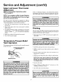
Thermostats
Temperature
The thcrmosvat(s) oi:this _atcr heater have bccn ]:actory set at a
position w-hid1 approximates 120°F (HOT) to reduce tile risk oi:
scald in juty.
HOT-Is
The uppcr thcrmostat is fikctorv sct at a position which approximates I L0 F tHOr) and Js ad:!usvable tl_a dtffi:rcnt watcr tempcratttrc is desired, Read ,all warnings in this mantel and on thc
watcr heatcr bcfi_re proceeding.
Settings
a thcrmostat sctting of approximatcly 120°F,
which w_ll supply hot _atcr at the most economical tcmpc_amrcs.
A-Is a thcrmosvat setting ot:appro_matcly 130°E
B-Is a thcrmostat sctting of approximatcly 140°E
C-Is a thcrmosvat setting of appro_matcly 150°I.
VERY HOT-Is a thcrmosvat setting of appro_matcly 160°E It
is t_ccommcndcd that thc did bcsct Iowcr w-hcncvcr possible.
NOTE: Wamr temperature range of 120°--140_F
mended by most dishwasher mamffact_aters,
UPPER THERMOSTAT
ADJUSTABLE
BEHIND
UPPER ACCESS
PANEL
16
recom-
Service
and Adjustment
(cont'd)
Upper and Lower Thermostat
Adjustment
(Refer to thermostat
"Thermostats")
illustrations
under
Fa_lurc to instil and maintain a ncw propcrly listcd tcmpcraturc-prcsst_rc rclicf walvc will rclcasc thc manufikcturcr from any
claim which might rcsult from exccssivc tcmpcratum or prcssurc,
NOTE: H is not necessary ¢_ adios€the apper thermostat.
However, if it is adjusted above the factory see poin¢ of
120°F (HOT) is is recommended that it not be set higher
than the lower thermostat setting.
AWARNING
If the temperature-pressure rellef valve on the appllance
weeps or dlschangesperlodically, this may be due to ther.
real expaeslon.Your water heater may havea checkvalve
instelled in the water line or a water meter wlth a check
valve. Consult your local Sears Service Center for further
informatlon. Do not plug the temperature-pressure rellef
valve.
Tbc uppcr and lowcr thcrmostats arc adjusvablc if a diffcrcnt
watcr temperature
is dcsircd. Read all warnings in thc
"Tcmpcratm'c- Rcgtdatlon"section bcforc proceeding.
]. Turn "OFF" thc electrical power to the _atcr hcatcr at the
juncdon box.
2. Take off the upper and/or lower access panel, insulation
block and pad,
Draining
3. The slotted adjustment (udng a scr_wdfivcr) can be turned
dock'wise (_
j/) to increase the temperature setting or
coEnter clock_Jse (_)
to decrease the temperature
setting,
Thc water hcatcr should bc @aincd if being shut dowt_ during
fi'cc-zing tcmpcraturcs, Also pcriodic draining arid clcaning of
scdimcnt from thc yank may bc ncccssary,
4. Replace the insulation block, pad and accesspanel.
• Bcfbrc beginning turn "OFF" the electric power supply to thc
5. Turn "ON" the power supply.
Temperature-Pressure
Valve Operation
water
heater,
A WARNING
.
I
HAZARD OF ELECTRICAL SHOCK] Before removing
any access panels or servlclng the water heater, make I
sure the electrlcal supply to the water heater is turned I
"OFF". Failure to do this could result in DEATH, SERIOUS BOD LY NJUFI_ OR PROPERTY DAMAGE.
Relief
Thc tcmpcraturc-prcssum rclicf v',dvcmust bc martwally opcratcd
at lcast once a ycar,
• CLOSE thc cold water inlet valve to the _atcr heater.
TEHPERATURE-PRESSURE
• OPEN a ncarby hot watcr _:aucctand Icavc opcn to allow for
d_ahfing,
RELIEF VALVE
o Connect a hosc to thc drain valvc and tcrmh_atc
adcquatc d_'ainor outdoors,
to an
• OPEN thc watcr hcatcr &'aln valvc to "allow_r tank dmJtfing.
DISCHARGE
NOTE_ If the water heater is going to be shut down and
drained for an extended period_ the drain valve sholdd be
left open with hose connected allowing water to terminate
to an adeql_te drain.
PIPE
AWARNING
• Close thc dra_n valvc.
The temperature-pressure relief valve must be manually
operated at least once a year. Caution shouldbe taken to
ensurethat (I) no one is in front of or around the outlet of
the temperatere.pressure relief valvedischargeline, and (2)
the water manually dischargedwill not causeany property
damage or bodilyinjury.The water may be extremely hot.
If after manually operating the valve, it fails to completely
reset and continuesto release water, immediately close the
cold water inlet to the water heater, follow the draining
instructions, and replace the temperatere-pressure relief
valvewith a new one.
• Follow _Filling thc Watcr Hcatcr"
qnstallation Instructions" sccdon,
instructions
in thc
• Turn "ON" powcr to the _atcr hcatcr.
A CAUTION
I
Never use thls water heater unless it is completely full I
water. To prevent damage to the tank and heatlng ele- I
ment, the tank must be tilled with water. Water must I
flow from the hot water faucet before turning "ON"
power,
;17
Service
and Adjustment
(cont'd)
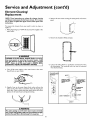
Element Cleaning/
Replacement
NOTE_ These instt_otions are written for dement deatzitzg
and element replacement for the lower dement. If it is ne;_'..ssary to deatz or replace the itpper demetzt_ then repeat these
instructions÷
4. Rcmovc thc two scrcw_ sccuring thc acccss panel, and rcmovc
pancl.
To rcmovc the element fl'om your tank in order to clean or
t_cplaceit:
1. Bcfore bcginning turn "OFF" thc clcctrlc powcr supply to the
watcr hcatcr.
5. Remove thc instllatlon block and pad.
AWARNING
.
[
HAZARD OF ELECTRICAL SHOCKI Before rem_mg
any access panels or servicing the water heater, make I
sure the electr;cal supply to the water heater ;s turned I
"OFF". Failure to do this could result ;n DEATH, SERIOUS BOD LY NJUR_, OR PROPERTY DAMAGE.
6, Lift out thc cab as shown to uncllp thc tcrmlnal covcr from
thc thcrmostat. Thc tcrminal covcr can now bc rcmovcd
fi'om thc thermostat,
2. Turn off thc watcr supply to thc watcr hcatcr at thc watcr
shutoffva.lve or water meter,
LT_Lo_t talb to oncTIT_
gcrmhlgl cover Fcom
JACKET
!!
TERMINAL
C_R
CLIFFEI) TO TI4ER.
HOg'TAT AT TH IS _
POINT
3. Awach a hosc to thc watcr hcatcr drain valvc and put thc
othcr cnd in a floor d_ain or outdoors, Opcn thc watcr hcatcr
drain valvc. Opcn a ncarby hot _atcr fSaucctwhich will mlicvc
pmssurc in thc _atcr hcatcr and spccd draining.
PLASTIC
TABS ON
/ _oqN4 SIDES OF
TERMINAL
C_R
14OLD IT IN
PI_C£.
THERMOSTAT
/_RACKET
_TANK
_L£MENT
AWARN!NG
The water passingout of the drain valve m_y be extremely
hot. Toavoidbeingscalded,make sure all connectionsare tight
and teat the water flowisdirectedawayfrom an),person.
:18
Service
and Adjustment
(cont'd)
]0. A ncw-gaskct should bc t_scd in all cascs to prcvcnt a posslblc watcr Icak. (Scc Elcmcnt Gaskct in thc "Parts Ordcr
List" Chart). Placc thc ncw dcmcnt gaskct on thc thrcad
sidc of thc clcancd or ncw clcmcnt and scrcw into tank,
sccuring tightly t_singan clcmcnt wrcnch.
TERMINAL
COVER
ON
UPPER
THERMOSTAT
:11. Closc thc watcr hcatcr d?ain walvcby turning thc handlc to
thc right (dockwisc}. Thc drain val(,c ls on thc Iowcr front
of thc watcr hcatcr,
] 2. Opcn thc cold _atcr supply valvc to thc _atcr hcatcr.
NOTE_ The €old water s_pply valve m_st be left open
when the water heater is in itse,
7,
Disconncct thc two _rcs on thc clcmcnt
old clcmcnt fi'om thc tank,
and tmscr_._v thc
13. To insurc complctc _lling ofthc yank, allow air to cxJt by"
opcning thc ncarcst hot watcr J:aucct, Allow watcr to rtm
until a consent flow ls obtalncd, This will lct air out ofthc
watcr hcatcr and thc piping,
A CAUTION
Never use this water heater unlessit is completely full of I
water. To prevent damage to the tank and heatlng ele- I
ment, the tank must be filled with water, Water must I
flow from the hot water faucet before turning "ON"
power,
8.
Clcan thc arca around thc clcmcnt opcning. Rcmovc any
scdlmcnt from or around thc clcmcnt opcning and lnsidc
the tank.
714. Chcck clcmcnt fbr _atcr lcaks, if Icakagc occurs, tightcn
clcmcnt or rcpcat stcps 2 and 3, rcmovc clcmcnt and rcposition gaskct, Thcn rcpcat stcps 10 through 14,
]5, Rcconncct thc two wircs m thc dcmcnt and thcn chcck to
makc susc thc thcrmostat rcmalns firmly, against thc st_rffacc
ofthc tank,
9. if you arc clcaning thc clcmcnt you havc rcmovcd, do so by
scraping or soaking in _4ncgar or a &-liming solution.
I
AWARNING
Replacement elements must (I) be the same volt_,geand I
(2) no g_eator wattage than Iistod on the model rating
plate affixed to the water he_tor.
;19
Service
and Adjustment
(cont'd)
This does not affect the water's vaste or color. The rod must be
maintained to keep the tank in operating condition,
Element Cleaning/
Replacement
(cont'd)
Anodc dctcrioration dcpcnds on watcr conducti_4t); not ncccssarily _atcr condition, A corrodcd or pittcd anodc rod indicates
high watcr conducti_49T and should be chcckcd and/or rcplaccd
morc often than an anodc rod that appcars to bc intact.
Rcplaccmcnt ofa dcplctcd anodc rod can cxtcnd thc li_ of your
_atcr hcatcr. Inspection should be conducted by"a Scars scr_4cc
tcchrddan, and at a minimum shotfld be chcckcd annually aftcr
the _arran_ period,
716. Replace the terminal cover on thermostat,
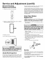
Drain Valve Washer
Replacement
:Yutt x 1_ _ tMck
NOTE: For replacemeut_ use a r,_ _ x v_
. washer
available at your nearest hardware store. For ordering a
replacement washer_ refer to the "Parts Order Lis_' se_-iom
17. Replace the insulation block and pad so that it complctdy
covers the thermostat and clement.
• Be_rc bcginning turn _OFF" the clectrica,1power supply to
the water heater,
AWARNING
.
I
HAZARD OF ELECTRICAL SHOCKI Before removing
any access panels or servicMg the water heater, make I
sure the electrical supply to the water heate_ _sturned I
"OFF". Failure to do this could result _n DEATH_ SERIOUS BOD LY NJUR_ OR PROPERTY DAMAGE.
• Follow "Draining"
instructions
in the _Scrvicc and
Adjustment" section.
• Turning counter clockwise, remove the hcx cap below the
screw-handle,
• Remove the _ashcr and put the new-one in placc.
•Scrcw¢ the handle and cap assembly back into the drain vdvc
and rctightcn t_sing awmnch, DO NOT OVER TIGHTFN.
• Follow _Filling thc Watcr Hcatcr" instructions
in thc
qnsvallation Instructions" scction,
• Chc& for leaks.
] 8. Replace access pancl.
19. Turn "ON" electric power to water heater.
• Turn "ON" dectric power to the _atcr heater,
_
_, CAUTION
.
Neve_ use this wate_ heate_ unless it is completely full orI
water. To prevent daumageto the tank and heating element, I
the tank must be filled with water. Water must flow from
the hot water faucet before turn ng ON'
Anode
HANDLI=
AND
Service
power.
Before calling for repair sctMcc, mad thc Start Up Conditions
and Operational Conditions fbund in the Troubleshooting
Guide of'this manual,
If'a condition persists or you arc uncertain about thc opcratton
ofthc watcr hcatcr,lct a qualificd pcrson chcck it out.
Rod Inspection
The anode rod is used to protect the yank from corrosion. Most
hot watcr tanks arc cquippcd with an anode rod. Thc submerged rod sacrifices itsdf'to protect the tank. Instead of'corroding the yank water ions attack and cat away the anode rod,
Contact SEARS Repair Services
(1-800_i69-4663),
2O
at 1-800-4-MY-HOME
Troubleshooting
Guide
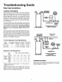
Start Up Conditions
THERMAL
EXPANSION
@
HOT
PRESSURE
REDUCING
VALVEWITH
BgPASS
Watcr supply systems max; bccat_sc of such events as high line
pressure, fi"c@cnt cut-olin, the cffacctsol?wascr hammcr among
othcrs, havc inst',dled dcviccs such as presst_rc redudng valvcs,
check vdvcs, back flow prevcntcrs, ctc,,,m control these 9'pcs of"
problems, Whcn thcsc dc_4ccs arc not equipped with an intcrn'al
by+pass, and no other measures arc taken, the dc_4ccs cause the
_atcr _wstcm to bc dosed, As _atcr is heated, it expands (thermal expansion) and closed _wstcms do not allow for dre cxpansion of hcatcd _atcr,
(2)
The water within the waer hcaer yank _pands as it is heated and
increases the pressure of the vcatcr xTstcm. If the rcheving point of
the vcatcr heater's remperature_pressure relief valve is reached, the
v0vc will relieve the _ccss prcasure,The tenzperatuee-preasm_e
relief"valve is not intended for the comtant m.Jiefof thermal
_panslon. This is an unacceptable condition and must bc co>
retted,
PRESSUREGAUGE
WATER
SHUTOFF
RECOMMENDED INSTAIJ_A_ ON
(VERTICAL MOUNITING)
It is recommended that any devices installed which could crcase a
closed svsrem have a by-pass and/or the s!_stcm have an expansion ta6k to relieve tl_c pressure built b_ thermal cxpanslon.
Thermal expansion tanks arc available f}om Sears stores and
through the Scars Service Canters. Contact the Ioca.1pltmtbing
inspector, water supplier and/or the Sears Service Center for
assistance in controlling these situations.
WATER H EA_ER
COLD WATER
INLET FITTIhlC
HOT
Thermal
STRAPPING
Expansion Tank Specifications
Modd
Tank Capacity
Ntmtbcr
ln Gallons
153.33 ] 020
2
Dimensions in lnchcs Pipc Fitting
Diamctcr
l.cngdl
On Tank
8 inchcs ] 2_ inchc* _" Male
153.3371050
]] inches ]4_inchc*
5
Expansion
Expansion
Tank
Capadty
Nccdcd
COLD
FLOOR,CEILING
jOISX,ETC.
Tank Sizing
Inlcd'
Watcr
Pressure
40psi
50psi
60psi
70psi
80psi
(3)
PRESSURE
REDUCING
VALVEWITH
BY-PASS
_"Malc
@
Chart
PRESSUREGAUGE
Watcr Hcatcr CapacagT ,Gallons)
30
2
2
2
2
2
40
2
2
2
2
5
INLET COLD
WA'_E R
SHUTOFF
50
2
2
5
5
5
66
5
5
5
5
5
AL_EPdhlATERECOMMENDED
INSTALLATION
80
5
5
5
5
5
(HORIZONTAL MouEn'ING)
STRANGE
SOUNDS
Possiblc noiscs duc to cxpansion and contraction of somc mctal
parts during pcrio& of"hcat-up and cool-down do not represcnt
harmfialor dangerous conditions,
*Highast recorded inlct wascr pressure in a 24 hot_r pcriod or
regulated _atcr prcssure,
NOTE= Expansion tanks arc prc-chargcd with a 40 psi air
charge, If thc i,olct watcr prcssurc is highcr than 40 psi, thc
expansion tanks air pressurc must bc adjustcd to match that
pressure, but must not bc highcr than 80 psi.
271
Troubleshooting
Operational
SMELLY
Guide
(cont'd)
Conditions
WATER
RUMBLING
rn cach _atcr hcatcr thcrc is ins_licd at Icast onc anodc rod (scc
parts scction) for corrosion protcction of tilc tank, Ccreain watcr
conditions wili causc a rcaction bctwccn this rod and tilc _atcr.
Thc most common complaint associatcd with tilc anodc rod is
onc of a "rottcn cgg smcll'. This odor is dcrivcd from hv&'ogcn
sulfldc gas dissolvcd in tilc watcr, Tbc smcll is tilc rcsult of_ur
Fkctors _-Mch mt_t all bc prcscnt for thc odor to dcvclop:
a, a conccnrwation of stdfiktcin thc supply _atcr,
b, little or no dissolved oxygen in the water.
c, a sulfate rcducing bactcria within the watcr hcatcr.
(This harmless bactcrh is non-toxic to humans.)
d, an cxccss of activc hydrogen in thc tank. Tbis is causcd
by the corrosion protcctivc action ofthc anode.
NOISE
ln somc watcr arcas, scalc or mincral dcposits will build up on
your hcating dcmcnts. This buildup will causc a rumbling noisc,
Follow Elcmcnt ClcaningiRcplaccmcnt
instructions to clcan
and rcplacc thc clcmcnts.
HIGH
TEMPERATURE
SHUT
OFF
SYSTEM
Thc watcr hcatcr has a high limit shut off systcm with a rcsct
button Iocatcd on thc thcrmostat.
Follow thc rcsctting instructions
bchind thc acccss pancl.
Smclly _atcr may bc climinatcd or rcduccd in somc watcr hcatcr
modcls by rcplacing thc anodc(s) _4th onc oflcss activc matcrial,
and thcn chlorinating
thc watcr hcatcr rank and all hot _atcr
lines. Con_ct thc local Scaa's Scr_4cc Center for furthcr informa+
tion conccming an Anodc Rcplaccmcnt K t//900
453 and this
Chlorination
Trcatmcnt,
which
rcfcr to thc high limit
NOTE, Ifyoor water heater is €onnected to an "OFF PEAK"
dock, and uses the "3 wire lead" wiring diagram in the
"Wiring Diagram" section, than the water heater will have a
hi-limit on both the _pper and lower thermostats÷ Follow
the insm*ctlons to reset the hi-limit behind the upper and
lower access panels÷
lf thc smclly watcr pcrsists aftcr thc anode rcplaccmcnt and dllorination trcatmcnt, wc can only suggcst that continuous chlorinat{on and filtcring conditioning cquipmcnt bc considcrcd to
diminatc thc watcr problcm.
* Bcforc bcginning, turn "OFF" clcctrical powcr supply to thc
watcr hcatcr.
Do not rereov¢ the anode leaving the tank _nprotectexL By
doing so, all warranty on the water heater tank is voided.
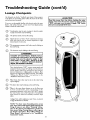
"AIR"
IN HOT
WATER
FAUCET'S
AWARNING
HYDROGEN GAS: Hydrogen gas can be produced in a
hot water system that has not been used for a long period of tlme (generally two weeks or more). Hydrogen gas
is extremely flammable and explosive. To prevent the
possibil;ty of injury under these cond;tions, we recommend the hot water faucet be opened for several minutes at the kitchen s;nk before any electrical appl;ances
wh;ch are connected to the hot water system are used
(such as a dishwasher or wash;ng machine). If hydrogen
gas ls present, there will probably be an unusual sound
skn;lar to alr escapingthrough the pipe as the hot water
faucet is opened. There must be no smoking or open
flame near the faucet at the time ;t ls open.
AWARNING
HAZARD OF ELECTRICAL SHOCKI Before removing
any access panels or sarvlclng the water heater, make
sure the electrlcal supply to the water heater ;s turned
"OFF", Failure to do th;s could result in DEATH, SERIOUS BODILY INJURY,OR PROPERTY DAMAGE,
LL
Troubleshooting
HIGH TEMPERATURE
(cont'd)
SHUT
Guide
OFF SYSTEM
(cont'd)
NOT
• Rcmovc thc ir_sulatior_block and pad,
Oft the
• Rcsct thc high limit by pushing lrt thc rcd button markcd
"RESET",
_
OR
NO
HOT
WATER
in a _tcw i_tsvallasion,thc watcr hcascr may not bc propcrlv
co_mcctcd. Makc surc thc cold watcr supply walvcis 6pcJ;,
Rc,-i_ and chcck piping iastallasio_t, Makc surc that thc
cold _atcr linc is co_mcctcd to thc cold _atcr inlct to thc
watcr hcascr and thc hot watcr Ilnc to the hot watcr outlet
* Rcmovc thc two sct_cwssccuri_tg thc acccss pancl and rcmovc
pand,
O_
ENOUGH
*
-¢¢-atcr hcascr,
Makc surc thc clcctrical supply to your watcr hcatcr is
"ON",
Chcck _r loose or blown fuscs in your watcr hcatcr circtfit,
Circtfit brcakcrs wcakcn with agc and may not handlc thcir
ratcd load and should bc rcplaccd.
RESETBU'I-I'ON
@
o
Makc ccrvaJn thc disconncct switch, if uscd, is in thc "ON':
position,
o
Chcck to scc thc clcctric scr_4cc to your housc has not bccn
intcrruptcd. If this is thc ¢._c, con_ct thc clcctric company;
o
Arc thc thcrmostats sct to thc dcsircd tcmpcraturc?
"Tcmpc_aturc Rcgulation"scction.
o
rf you had cxpcricnccd vcoT hot watcr and now _to hot
watcr, thc problcm t_3avbc duc to thc high tcmpcraturc
shut Off"system. See H_gh Tcmpcrasurc Shut Off" S.tcm"
in thc Troublcshooting sccrJon.
o
During vcry cold wcathcr, thc incoming wascr will 'also bc
coldcr and it will rcqulrc a lor_gcr timc to bccomc hcatcd.
o
Thc hot _atcr usagc may cxcccd thc capacig, oi: thc watcr
hcascr. 1Tso, wait f_r _atcr hcascr to rccovcr al_cr abnormal
dcmand. Also cxaminc pipcs and _aucct's for possiblc wascr
Icaks,
•
H:you can not dctcrminc thc problcm, thc_t call thc Scars
Sctx-iccDcpartmc_tt.
runN_rr
• Rcplacc thc i_tsulation block and pad so that it complctcly
covers the thcrmos_t and clcmcrtt.
* Rcplacc thc acccss pancl,
* Turn "ON" clcctric power to thc _atcr hcascr.
A CAUTION
If the high I;mit must be reset again, call Sears Service
Department to find out why the high I;mit turned "OFF"
the electric power.
WATER
IS TOO
Scc
HOT
Adjust thc thcrmostat to a lowcr sctting, Scc tllc _Tcmpcrasurc
Regulation" scction,
23
Troubleshooting
Guide
(cont'd)
Leakage Checkpoints
Usc this guide to check a q,eaking" watcr hcatcr. Many st_spcctcd "l,cakers" are not leaking tanks. Olden the source of the water
can bc found and corrcctcd.
CAUTION
I
lfyou are not thoroughly J:amiliar _4th clcctric codcs, thc watcr
heater, and safety practices, contact your local Sears Service
Center to check the water heater.
®
®
©
*Condcnsation may bc sccn on pipcs in humid wcathcr
or plpc connections may bc Icaking.
Thc primary anodc rod may bc lcaklng.
Small amounts of water fi'om temperature-pressure
rclicf valve may bc duc to thermal expansion or high
watcr pressure m your arca.
tcmpcraturc-prcssurc
@ *Thc
the yank fi_ttlng.
®
rclicf waivemay bc Icaking at
Thc clcmcnts may bc leaking at the tank fittlng,
A WARNING
HAZARD OF ELECTRICAL $HOCKI Before
removing any accesspanelsor servidng the water
heater, make sure the electrical supply to the
water heater _sturned "OFF". Failure to do this
could result _n DEATH_ SERIOUS BODILY
INJUR_ OR PROPERTY DAMAGE.
Turn dcctrical powcr "OFF", rcmovc acccss pancls and
insolation block and pad. If lcaking around clcmcnts,
I_bllow propcr draining instructions
and rcmovc
element. Rcposltlon or replace gaskct on element. Place
element into opcnlng andtightcn scct_rcly.Then follow
"Filling thc Watcr Hcatcr" instructions in thc
"Insvallatlon Instructions" section,
@
Water from drain waivemay bc duc to thc vdvc being
opcncd slightly.
@ *Thc drain valvc may bc lcaklng at thc tank fi'Ltting.
in the water heater bottom or on thc floor may
@ *Water
bc from condcnsation,
loosc conncctions
or the
tcmpcraturc-prcssurc
rcllcf valvc. DO NOT replace
the water heater until a flail inspection of ,all possible
water sourccs is made and ncccssary corrcctlvc steps
takcn,
bcakagc from othcr applianccs, watcrlincs,
seepage should also bc chcckcd,
I
Read this manual tint, then before checking•the water I
heater make sure the electric supply has been turned
"OFF", and never turn the electric supply "ON" before
the tank s completely full of waten
®
or ground
NOTE: *To check where threaded portion enters
tank, insert cotton swab betwcenjacket opening and
firtlng÷ If cotton is wet_ follow "Draining'
ins¢_ctions in the "Service and Adjostmen£ _ section and
then remove fitting. Pat pipe dope or _¢flon _ape on
the _hreads and replace. Then follow "Filling the
Water Heater" instractions
in the "Installation
Ins*Ja_ctlon¢' section.
24
Notes
25
Notes
26
Notes
27
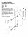
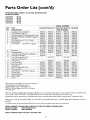
Parts Order
KE_IORE
POWER MISER
MODEL NUMBERS:
153.321340
153.321341
153.321440
153,321441
153,321540
TM
List
12 ELECTRIC
WATER HEATERS
30G al+
30G al+
40G al+
40GaL
50GaL
NOTE_ A
UPPER ELEMENT:Thesewater
3800wa_elemen_.
2
heaters areeq_ippedwith
P
LOWER ELEMENT: These water heaters are eqltipped with
factory installed convertible dements_ which can be operated
at 3800 watts or 5500 watts. Convertible elements are not
offered as replaeament parts.
3
23
4
ELEMENT ORDERING INFORMATION
If a rcplaeement 3800 waR, 240 volt element is needed, o_des
item no. 42-31906 _eplaeememt elememt*fiat file dine ofinstallatlon, file water heater was converted to operate at 5500 watts,
order item numbes 42-31908 replacement element. (See model
rating plate "If Converted" box).
NOTEt B
These water heaters are equipped with a Roto-SwirW dip
atbe to retard a b_ild-ltp of dissolved solids÷
2]
22
18
]7
5
]2_
11
]3
]4
28
6
Parts Order
KENMORE
POWER MISER
MODEL NUMBERS:
153,321340
153,321341
153,321440
153,321441
153,321540
KEY
NO.
TM
List (cont'd)
12 ELECTRIC
WATER HEATERS
30GaL
30GaL
40GaL
40GaL
5OCTal,
PART
DESCRIPTION
153.321340
1,
2,
3,
4,
5,
6,
7,
8,
Tcmpcraturc-PressureP-.elic
f Valve:*
Heat Trap Nipple (Odd !nlct)
Secon&W Anodcw/Heat TrapNipple (Hot Ot*tlct)
Roto-SwklTM Dip Tube (SccNOTF,"B"pa_c28)
Drain Valve
Drain ValveWashcr (_q/'x %% _" _lick)**
FJcmentGasket
ItowerElement*
(So:NOTF,"/\'on page28)
9,
10,
11,
12,
13,
Bt_s BarKit
Thcmle*tat Brac'_t
2 Pole Thermostat (TwoWke LeadModcls)__,'*
Tcrminal Co,a:r& Barrier
ItowerThermostat wiHi I.imit
(ThrccWkc I_d Models)it*
Tcrmlnal Cov_:r
ItowerAccessPanel
UpperAccessPanel
Terminal Cov_:r
Upper Thermostat w/Hi limit*
Thermostat Brac'_t
Upper Element* (SeeNOTE '%*p@c28)
FJ.cmentGasket
Model Rating Plate )
PrimaryAnode
Manual
9002403
9003931
9003937
9003501
9003911
9001584
9000308
3800Wa=
4231906
5500Wa_
4231908
9001591
9000309
4231919
9002276
14,
15,
16,
17,
18,
19,
20,
21,
22,
23,
/I
153.321341
9002403
9003931
9003937
9003501
9003911
9001584
9000308
3800Watt
4231906
5500Watt
4231908
9001591
9000309
42 371918
9002303
9002671
9002671
9002303
4231917
9000309
4231906
9000308
0270182
9003927
9002671
9002671
9002303
4231917
9000309
4231906
9000308
0270182
9003927
MODEL NUMBERS
153.321440 153,321441
PART NUMBERS
9002403
9002403
9003915
9003915
9003941
90039471
9003929
9003929
9003098
9003098
900:1584
9001584
9000308
9000308
3800Watt
3800 Watt
42 31906
42" 3" " )06
_
5500 Watt 5500 Watt
42 31908
42" 3" " )08
_
90071591
90015971
9000309
9000309
4231919
9002276
o - . _.
423
)18
9002671
9002671
9002303
4231917
9000309
42 31906
9000308
02707182
9003928
184730-000
9002303
900267:1
900267:1
9002303
423
"," .)li
t "
9000309
4_" 3" " )06
_
9000308
0270182
9003928
153,321540
9002403
9003909
9003939
9003919
9003098
9001584
9000308
3800Watt
4231906
5500Watt
4231908
9001591
9000309
4231919
9002276
9002671
9002671
9002303
4231917
9000309
4231906
9000308
0270182
9003728
*Thcsc parts am 'alsoava[lablc at most Scars rceail storcs.
**Also awailablc at most hardwarc storcs.
_Rcplaccd only on return ofdamagcd plate,
_'_Rcfcr m Wtring Diagram Section _r vcriflcation,
//Not Illustrated
Now that you have pttrdlascd this watcr hcatcr, should a nccd cvcr exist for rcpair parts or scrvicc, simply convact any SFARS Scrvicc
Ccntcr or call 1-800-4-?vW-HOME (1-800-469-4663), Bc sttrc to providc all pcrtlncnt _:actswhcn you call or _4slt.
All parts listcd may bc ordcrcd from any SFARS Scrvicc Ccntcr, most Scars storcs and by calling 1-800- 366-PART (1-800- 36@7278),
If thc parts you nccd arc not stockcd locally, your ordcr ,MI1 bc clcctronically
handling.
The model number
WHEN ORDERING
MODEL NUMBER
SERIAL NUMBER
transmlttcd
to a SEARS Repair Parts Dlstrlbu6on
of the water heater w411bc found on the model rating plate located above the access pancl,
REPAIR PARTS, ALWAYS G_'E
PART DESCRIPTION
PART NUMBER
THE FOLLOWING
THIS IS A REPAIR PARTS LIST, NOT A PACKING LIST.
29
INFOILMATION,
Ccntcr _r
Parts Order
KENMORE POWER MISER
MODEL NIJMBERS:
153.321541
153.321640
153.321641
153.321840
153.321841
TM
List
12 ELECTRIC
WATER HEATERS
50G al+
66G al÷
66G al÷
80Gal.
80Gal.
NOTE, A
UPPERELEMENT,
3800wa_elemen_÷
TEesewater
heateesareeq_ippedwith
LOWER ELEMENT:
These water heaters are eqttipped with
factory installed convertible elements, which can be operated
at 3800 watts or 5500 watts. Convertible
elements are not
offered as replacement parts,
ELEMENT ORDERING
INFOI_MATION
If a replacement 3800 waR, 240 volt elememt is zleeded,
item no. 42-31906 zeplaeeme_t eleme:ah _at file dine of
lation_ file water heater was ennverted to operate at 5500
order item mtmbes 42-31908 replacement element. (See
eating pLate "ff Converted" box),
3
23
I
o_des
instaL
watts,
model
NOTEt B
These water heaters are eqMpped with a Ro*o-Swirl TM dip
atbe to retard a b_ild-ltp of dissolved solids÷
¢t
18
17
7
13
]4
\
3O
4
Parts Order
KENMORE
POWER MISER
MODEL NUMBERS:
153,321541
153,321640
153,321641
153,321840
153,321841
KEY
NO.
1,
2.
3.
4.
5.
6.
7.
8.
9,
10.
11.
12,
13.
14.
15.
16.
17.
18.
19.
20.
21.
22,
23.
/I
TM
List (cont'd)
12 ELECTRIC
WATER HEATERS
50GaL
66GaL
66GaL
80G al,
80G al,
PART
DESCRIPTION
153.321541
153.321640
9002403
Tcmpcratur_PressureP.elicfValve*
9003909
Heat Trap Nipple ((;old Ink,)
SecondatT Ano& wiHcat Trap Nipple (Hot Ot*11¢0 9003939
9003919
Roto-SwirlTM Dip Tube (SeeNOTE "B"page30)
Drain Valve
9003098
9001584
Drain ValveWa&cr (_q/'x %"x_" thick)**
FJcmentGasket
9000308
3800Watt
I.owerElemcnt*
(SeeNOWF.*.4"on page30)
4231906
5500Watt
4231908
Bt*ssBar Kit
9001591
Thcmlostat Brac"_t
9000309
I
2 Polc Thermostat (TwoWire LeadModels)t;'*
Tcrmind Cov_r& Barrier
I
I.owerThermostat wiHi I.imit
42319:18
(ThreeWLrcI_d Models)it*
Tcrminal Cov_:r
9002303
I,owerAccessPanel
9002671
9002671
UpperAccessPanel
Terminal Cov_r
9002303
Upl_crThermostat wlHi Iimit*
4231917
Thcrm_tat Brac"_t
9000309
4231906
Upper Element* (SeeNOTE "A*page30)
Element Gasket
9000308
0270182
Model Ratin{_Plate "]"
9003728
PrimaryAnode
Manual
9002403
9003931
9003940
9003933
9003098
9001584
9000308
3800Watt
4231906
5500Watt
4231908
9001591
9000309
4231919
9002276
9002671
9002671
9002303
4231917
9000309
4231906
9000308
0270182
9003728
MODEL NUMBERS
153.321641 153,321840
PART NUMBERS
9002403
9002403
9003931
9003936
9003940
9003935
"9"33
.003..
9003933
9003098
9003098
900:1584
9001584
9000308
9000308
3800Watt
3800 Watt
42 31906
4_" 3_" )06
t
5500 Watt 5500 Watt
42 31908
42o 3- • )08
90071591
90015971
9000309
9000309
42 3:1919
9002276
4231918
9002303
9002671
9002671
9002303
4231917
9000309
42 31906
9000308
02707182
9003728
184730-000
900267:1
900267:1
9002303
4_","t
3 )1 i
9000309
4_" 3" " )06
_
9000308
0270182
9003932
153.321841
9002403
9003936
9003935
9003933
9003098
9001584
9000308
3800Watt
4231906
5500Watt
4231908
9001591
9000309
I
I
4231918
9002303
9002671
9002671
9002303
4231917
9000309
4231906
9000308
0270182
9003932
*These parts arc 'alsoarailable at most Scars rcvail atorcs.
**Also awailablc at most hardwarc stores.
yRcplaccd only on return of damaged plate.
_'_Rcfcr to Wtring Diagram Section fi)r vcrification.
//Not Hluatrated
Now that you have pttrdlascd this water hcatcr, should a nccd cvcr exist for rcpair parts or scrvicc, simply convact any SFARS Service
Center or call 1-800-4-?vW-HOME (1-800-469-4663). Be sttrc to provide all pertinent _:actswhen you call or _4sit.
All parts listed may, be ordered from any SFARS Service Center, most Scars stores and by calling 1-800- 366-PART (1-800- 366-7278).
If thc parts you nccd arc not atockcd locally, your ordcr wdll bc clcctronically
handling.
The model number
_q-IEN ORDERING
MODEL NUMBER
SERIAL NUMBER
THIS
transmittcd
to a SEARS Repair Parts Distribu6on
of the water heater w411be found on the model rating plate located above the access pancl,
REPAIR PARTS, ALWAYS GIVE THE FOLIA)WING
PART DESCRIPTION
PART NUMBER
IS A REPAIR PARTS LIST, NOT A PACKING
LIST.
31
INFOP_IATION,
Ccntcr _r
FUI,L
ONE
YEAR
WARRANTY
ONWATER
HFATER
Forone year fi'om tlxe dare of pro'chase, when yo_' Sears Kenmo_ ,a_ter heater is inst,'dled mid operated in a dngle-fm_i]y
residence in
accordance with the h_structions in tlxis mmau,'d,Sears wRl:
I.
2.
Repairdefects in maseria] or workmmaslxip in this water hmte_; free of chm'g¢.
Furnish gad install a nm,¢c_'tent modal water heater ofequM capacity and quMiD; f_e of chaR,,e, if a leak occurs in the trunk.
LIMITEDWARRANTY ON TANKS THAT LEAK
After one year gad through 12 yem'sfrom the date of purchase for,a_ter heaters xksedin a single-family residence, if a leak occurs in tlxe
ink, Sears will furnish a note current modal ,a_ter heater of equal capacity and quality. You will be chm_{edfor any inst,'dlation.
I,IMITED WARRANTYON PARTS
After one year gad through 12 yem'sfrom the date of purchase, when your Sem's Kenmor¢ water heaser is used in a dngle-fm_ily
residence and is inst,'dlc_dand operated in a_rdance witl: tlxe inft*rmation in tlxis mmau,'d,ira part fails due to a maseria]s or
workmmaship, Sem'swill _mish a replacement free of chm'b,¢. You will be charged for labor.
If the ,a_ter heater is subjected ru commercial, h_stiturional, in&tstri,,dor use in _ddences of two fm_ilie_ or mote, tlxe above warrmaty
ctwer,%,efi._rr,mks that I_tk is _Tecti*_ef_r 2 yemx from tlxe da_ of purchase gad tlxe abtwe parts ,a_rranry is e£'ecri*_ f_r 1 year fi'om tlxe
date of p_'ch_se.
To obtain wm'ranty serdce, SIMPI _- CALL 1-800 -4M_r'-HOME (1-800-4694663).
n use m takeUn ted State&
"This ,a_rrmaty applies only while this product is
This wm'ranty gires you specific legal righr_ and you may ,'dsohare other rig,lxts which vary from state to state.
SE_LRS,RO 318UC'( AND CO,, Dept, 817 *¢¢_,l IOF _MAN ES']'_YFES, IL 60179
The prlo¢ ofyo_ water heater does not indode a free checb.tp sc.a_o¢call. On water hearerinsvaJlat_ons
arrangedbyScars,S_rs warrants the installation.
A charge will be made on servicec;_11s
duc to poor or incomplete insval].ation,These include:
a.kdiust_ngtkemmsvat b, I._k* in p_pesor fittings
c. Condensation
MASTER PROTECTION
AGREEMENTS
• Fast help by phone - phone support from a Sears te&niciaa on
producrsrequiftng in-home repair,ph_sconv_:n[entrepairscheduling.
Congratulationson making a smart purchase,Your new Kenmorc_product is dcsigncd and manufacturedfor y_ts of dependableoperation.But
like all products, it mW require prcv_:ntiv_:
mainrcnancc or repair from
time to time, That's w]:en ]:as4nga Master Protection Agreement can
sav_:you money,and aggravation,
Purchasea Master Protection Abwccmcntnow and protect yourselffrom
un_pcctcd hassleand _pcnse,
The Master ProtectionAgreement_so hdps _tcnd the life of your new
product, Hercs whats hduded h _c Agreement:
• Ex-pertS_wlce byour 12,000 profe_donalrepairspecialists.
• Unlimited service and no charge for parrs and labor on _1 cove:red
repairs.
• '%lo-lemon_ gtmrantec- replacementofvour coveredproduct [ffiour
or more product failuresoccur wkhin twelve:months.
• Power xttrge prot_tlan againstdcctr[cal damage due to power fluctuations,
• Rantal rdmb_ant
than promlscd,
if repair of your cove:redproduct rakeslonger
Once you purc_e the Agreement,a simple phone call is fll that it takc_
_Sur
you to *cheduleservice,You can call anytime day or night,or seheddc a scr_@cappointment ondinc.
has over 12,000 professionalrepair spedallsrs,who have acecssm
over 4,5 million qual[t),parts and arxc_)r'_m,That's the kind of pmfessionali*myou can count on m hdp prolong the I_'_c
ofyour new purchase
£r y_ts to a)me, Purchaseyour MasterProtection Agreementtoda¢.
Some limitations and excl_iom appiT For prices and additional
information call 1-800-827ff_655
SEARS
INSTALLATION
SERVICE
• Prod_tctrepine,anent ifyour cove:redproduct can'tbe £xcd,
• Anmtal Pr_nti-,_
&xtgc.
Malntenance Check at your request - no extra
For Scatspro_ional [_srallationof home appliances,garagedoor openers, water 1:eaters and ot1:er major home items, in the U.S,A,, call
1-800d-MY-HOME*.
For in-home
major brand repair service
Call 24 hours a day, 7 days a veeek (U,S,A, a,d Ca,ado)
1-800-4-MY-HOME
_
(I-800-469-4663)
WMfM_*,_dL_P_* CO I'1_
The modal number of your water ]:eater is _5oar_don the model rating plate on t_e front of the water heater,
Sears, Roebuck and Co., Hoffman Estates, IL 60179 U.S.A.