1
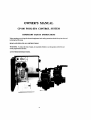
CP-100 POOLISPA CONTROL SYSTEM
INSTALLATION AND OWNERS MANUAL
$hemtd11' Pool Products"
Because mliabiliry maftem most
INSTALLATION MANUAL
IMPORTANT SAFETY INSTKUCT1QNS
SYSTEM INCLUDES
TOOLS REQUlRED
EQlJlPMENT LOCATION
RECOMMENDED HYDRAULIC SCHEMATIC
PLUMBING REQtlI REMENTS
LX-100 POWER CENTER
HIGH VOLTAGE WIRING
GENERAL
SYSTEM POWER
EQUIPMENT POWER
LOW VOLTAGE CABLES
LOW VOLTAGE WIRING
CP- 100 INDOOR CONTROLLER
USING THE CRIMPING TOOL
VALVE ACTIJATORS
WATER TEMPERATURE SENSOR
HEATER CQNNECTIONS
DUAL THERMOSTAT GAS kIEA1'EK
SINGLE THERMOSTAT GAS HEATER
ELECTRIC HEATER OK HEAT PUMP
SYSTEM OPTIONS
SPA-SIDE llEMOTE CONTROL
POOL CLEANER
AUXILlARY VALVE
SPA WATERFALL CONTROL
FREEZE PROTECTION
SYSTEM START-UP
OWNER'S MANUAL
IMPORTANT SAFETY INSTRUCTIONS
SAFETY FEATURES
HEATER PROTECTICIN
POOL CLEANER PROTECTION
INDOOR CONTROLLER
Equipment Pushbuttons #S, #I, #2 and #3
EQUIPMENT STATUS INDICA'I'UKS
TEMPERATURE Display
USING YOUR SPA
POWER CENTER
FILTER PUMP and POOL CLEANER Time Clocks
SPA Scrvicc Switcl~
FILTER Service Switch
AUXI, AUXZ and AUX3 Service Switches
HEATER Switch
PUhdP DELAY Slatus Light
POWER ON Stutus Light
MOTORIZED VALVES
SYSTEM OPTIONS
SPA-SIDE REMO'rfi CONTROL
SPA WATERFALL CONTROL
FREEZE PROTECTION
MAINTENANCE
CLEANING THE SPA
WINTERIZING THE SYSTEM
TROUBLE-SHOOTING
GENERAL
NOTHING OPERATES
FILTER PUMP DOES NOT OPERATE
FILTER PUMP DOES NOT TIJRN OFF
POOL CLEANER DOES NOT QPEMTE
HEATER DOES NOT OPERATE
SPA WATER LEVEL DROPS
INSTALLATION MANUAL
CP-100 POOL-SPA CONTROL SYSTEM
IMPORTANT SAFETY INSTRUCTIONS
All wiring must be performed by rr qualified elech-icisn.
Basic safety precautions and locd codes should always be followed when installing and using this electrical equipment.
REAP AND FOLLOW ALL INSTRUCTIONS.
WARNING: To reduce the risk of injury, do not permit children to use this product unless they arc closely
supervised at all limes,
SAVE THESE INSTRUCTIONS.
SYSTEM INCLUDES
CPlOO Conmller.
LXlOO Power Center or LXlUOL Load Cenler.
CVAZQTValve Actuators, P/N 263045 (2qty).
TSSL Water Temperature Sensor.
2COND flook-up Cable (25flspuul).
6COND Cornmu~ricationCable (2qty 150n sppnls).
Modular Connectors for Comnlunicalion Cable.
Mounting Hnrdwarc for CP- 100.
TOOLS REQUIRED
3/16" dia. DdII (for mounting CP- LOO Uon~ller).
5/16" dia, Drill (for mounting TS-5L Water Tempralure Sensor).
Crimping Twl for mounting Modular Connectors to Communication Cable: (modal TOOL-6)
EQUIPMENT LOCATION
With the exception of the Spa-side Remote Control (which is UL listed for ins~allntionright at the tile-line
of the spa), all equipment must be located five feet or more from the water's cdge.
1.
2.
3.
4.
5.
LX-100 Pawer Center at the equipment site.
CP-IN (Inntroller inside the hvuse or other weather-pmtectd arm.
CVA-24 Valve Actlurtors at valves to bc motorized.
TS-5L Water lkmperature Sensor at the fitter pump,
Spa-sidc Rcmote Control (optional)a1 spa wall or decking.
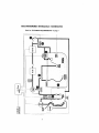
RECOMMENDED HYDRAULIC SCHEMATIC
Refer for "PLUMBINGREQUIREMENTS"on page 3
PLUlVIBING REQUIREMENTS
Plumb system in accordance with "RECOMMENDEDHYDRAULIC SCHEMATIC"on page 2, lmal
c d e s und the following guidelines.
Bring all lines back to the equip~nentpad.
1.
Spa should be at o r above the level o f the pool.
I f spa is attached to pool, provide a dam bctwcen the bwo bodies of wilter to allow spa overflow
into pool, I f spa i s not attached to p w l , an overflow. sufficient i n size to carry full pump-flow,
must bt: installed at water level in tlie spa.
2.
Plurnh a three-port Intake Valve on the suction-side o l the filter pump, so that cearer port of vnlvr
is connected to the pu111p inlet.
Connect spa suction to one side o f Intake Valve, and pool suction to the othcr side.
3.
Plurnh a three-port Return Valve on the return-side of the heater, so tllot rcturt~walcr will cnlcr
valve through the center pon,
Conncct spa return to one side of Return Valve, and pool return to the other side.
4.
A W spa make-up line (incot-prating a H" manual gate or ball valve and, for elevated spis, a '/I".
check'valvc) may bc provided to bypass the pool return line. l'his will enable some a l the chemically-balanced water from the pool to cycle through die spa. The manual valve will allow lhe
amount of bypas to be adjusted,
5.
If the spa is to be constructed i n concrete, special provision should be made ut this time for the.
installation of the Spa-side Remote Control.
Select n convenient location in the deck or above water level i n the spa wall (where the Spa-side
Ru~norewill not be submerged by the spa water). and install n 6" to 12" length of I-'/)'" pvc pipe to
pmvide r receptacle for the Spa-side Reniorc. The pipe should be level and protrude beyond the
finished surfilcc of the spa. I t will be cut back n later date.
Reduce p i p size down to $5'' or %iV
conduit, and run to proposed LX-IOU location at equipment
pad. Use swcep elbows for turns.
The Spa-ride Remote w l l l not be installed until spa construction is iwmplclc.
6.
For systems which incorporate a skimmer. it is possible to balance the amount of suction between
the skimmer and main drain for maintenance purposes.
This is uasily accomplished by installing a manual three-port mixing valve at the suction linc.
Plumb onc port to the skimmer and the other to the main dnin.
7.
If a "non-booster pun~p"pressure-sidepool cleaner is being used, plumb a manual three-port valve
between the filter pump and filter, with the third port plumbed to the pool cleaner linc. and install a
motorized two-porz Pool Cleaner Vaive at this line. The motorized valve will autr~~natically
open
wl~encvcrtlie Control System activates Ihe pool clmna.
8.
I f a booster pump pool cleaner i s being used. plumb the booster pump so that its suction-side i s
connected to the pool return, after the heater and as close to the ground as praaicnl.
Select a col~venientlocation to mount the LX-100 Power Center. Ensure h t the location is greikr than 5
frrt from the water's edge and no hurther than 15 feet from any motorized valves (otherwise Valve Actuator cables will need lo be extended).
Mount the 1.X-100 on a flat surface using appropriate screws lhrough the three cxtenlal mounting paints
located on the side of the enclosure, Do not drill and mount from inside the enclosure.
Looscn LOCK SCREW of hinged faceplate in left-side of LX-100,and swing open to expose the low-voltage compirtment. All low-voltage connections are made to the circuit board, in accordance with wiring
diagram lucated inside door.
The high-vottage wiring compnrtment is located behind service panel in right-side of LX-100.
HIGH VOLTAGE WIRING
GENERAI,
At khe equip~nentsite, install an electrical sub-panel wbh separate breakers for each load,
Circuit breakers should be readily accessible to the spa user, but installed at least 5 feet froin the water's
cdgu.
Make sure that the rnolor(s) on the equipment have built-in thermal protection.
At the LX-100, remove the service panel (at left) to expose the high-voltage compariment, and knock-out
the appropriate l~olesat bottom of enclosure to facilitate condui~mounting. Screw terminals are pmvidcd
for high-voltage corrncctions.
SYSTEM POWER
Provide a repiirate circuit b ~ a k e to
r power the system. Either 1 15 or 23OVAC cnn be used [ I 15V is preferable). System dnws less than I-Amp. The breaker will open all ungrounded supply conductors to comply with section 422-20 of the National Electrical Code, ANSVNFPA 70-1987.
Run approprialo wires from circuit breaker to high-voltage compartment of LX-100, and connect to top
renninal black in iiccordince wilh wiring label, which is marked SYSTEM IDOWER,
Install two jumper wires for 1 1 SV, or one jumper for 230V, according to wiring label.
EQUIPMENT POWER
Provide independent circuit breakers for R1 (FLTR), It2 (AUXI), TW (AUX2) and R4 (AUX3).
Run opproprii~tewires from breiers to high-voltage compartlnent of LX-100. and connect to LINE1 and
LINE2 sscrcw terminals at each terminal block.
Connect pumps and other high-voltage equipment 10 LOAD1 and LOAD2 terminals.
Each individual terminal block can be wircd for eithcr 115V or 230VAC.
Note: For 11 5V cquiprnent. only half of the terminal block will bt. used (ic: LINE1 rmd LOADI).
LOW VOLTAGE CABLES
Install cnble betwccn the low vokage colliparrment of the LX-100 Power Ce~lterilnd Ihc various pieces uT
equipmnent. Provide plastic or me~nllicconduit where cables run underground. through concrete, etc.
Note: Never install low voltage and high voltage wires in the sumc conduit. It is advisable to maintain s minimum dlsrance of 12" between parallel runs of low voltap snd AC currcnt-cnrrying wlrcs.
1.
2.
3.
4.
2 qty. separate I50foot spools a#6-conductor 26 AWG conrtnunication cable arc providd (w1e
black and one silver) to connect to h e CP-100 Controller.
Nore: Cable lubricant must be uscd when pulling these cables through tke condult.
25 feet of Zconductor 22 AWG cable is provided ro conncct the Warcr Tempcralurc Sensor.
CVA-24 Valvc Actuators are provided with 15 feet of 3-condactor cable.
The optio~~al
Spa-side ILniole Control is provided with necessnry ci~bleattached.
LOW VOLTAGE WIRING
CP-100 INDOOR CONTROLLER
Select iIcunvc~rictillecatiun irraidu the house or athcr weather-protcctcd area to nlount the CP-I00 Con~rulIrr. The overall wiclth of tlic Controller {with doors open) is II-W. The locarior~of the 6-conductor conimunic:~tioncables (on thr cunterline of the enclosure) shoultl thcrcfore bc? at least 5-'A" fro111any door
jamb, wnll corncr or other oblrti~cle.
Remove bilckplatc from Controller. Temporarily pull cables through large hole In hrekplate, and position
backplate on surface of wall, Make sure that backplutc is level and that ''TOP nomenclature is oriented
comctly, und mark the thrw rnounling points on the surfiice of the wall. With the backplate removed from
the wall. drill 3/16" diilrneter holes and insert mountiog anchors (included) into the three holes. Pull cables
through lurgc hole in hnckplate, and use the three 1 4 " screws to mount backplate to wall.
Use the Crimping Tool (model 'TOOL-6)
to attnch modular conncctoa at each end o f both cables. See
1ISING THE CRIMPING '~O'OOL.,below,
At the CP-100 Contmlter, plug the kilccr cable (with modulitrconllcctar attached) into the circuit board at
Socket # I (SII,VI?H), and plug the black cable into Socket#Z,
Use ttrc f ~ ~ tW
r r screw> (included) lo srotlnt CP- 100 Controller to the bickplate.
At the 1.X- 100 Power Ccntcr, plug the silver cable (with n~oduliwconnector attached) into the circuit bond
31 Socket #I(SLLVER). ;~nd
p l t ~ gthe black cable into Socket #2.
USING THE CRlMPlNC TOOL
Make sure thilt the end of the cnhle i s cut squsmly (not diagonully).
Insert thc cable hetwccn the stripper hlades of the tool until i t touche$ thc stop, Squeem the handles and
prrll the tool, maklng sure ihiit the cable stays perprndiclrlar to i ~If
. this i s done correctly, the outer jnclct
of the cubic will hc re~novcdwithsi~tdamaging the insirlation on the individual condtictors.
Pl;tcc a nrudt~lurconnccror in ihr tloldcr portion of the tool so that the fron~of the connector is against the
\top and the gold co~ltuctsbcc the crimper. Oricnt thu pwparcd cable so that the blue conductor is closcsb
to the tool liantllcs. :tnti insen cable into connector. Make certi~inthat the conductors are tlush with Lhe tip
of tltc connector and d i ~ c t l yunder the gold contacts. Squeeze thc hancllcs firmly to set the contacts i~nd
wcurc tlir cuhlc,
Note:
It is important that thc! orientation (blue conductor closest to tool handles) is identical at all
four cable cnds.
VALVE ACTUATORS
Reniovc knob, handle and four $crew?;from c;ip of valvc(r) to bc matorixcd, and rase thc four mounting
screws provided to mount Valve Actuntods) to valve(s).
Run cables to low-voltage wiring uompartn~ento f LX- 100, ond plug into circnit board at thc uppropriatc
Valve Socket:
Plug intake (suction) vslva into INT VLV Socket.
Plug return valve inta RET VLV Socket.
Plug auxiliary valvc (if applicable) inta AUX VLV Socket.
WATER TEMPERATURE SENSOR
Select a convenient location to mount thc Temperature Sensor (model TS-51,) in ihc plumbing syarcni
(after the intake valve, and before the hcatur).
Drill r 5/16" diamelcr hole in ihc pipe, irnd insert the Sensor.
p
Posi~ionclamp over the Senaar, antl gcntly tighten
Use n screwdriver to open the hose c l n ~ i ~(includrtl).
around the pipe. Caution: Ovcrtightening of clamp can cause deformation uf u-ring sci~l.
Run 2-conductor cable (25 R. ix included with InslallrbtianHardware package) between Scnsor Iociition
m d low-vollagc conlpartmcnt of LX- 100 Power Center.
At the Sensor, p;ay atlcntion to color coding (green caiiductor connccts lo grecn; red conductor connecls lo
red), and use 2 o f the cnnrp connectors (inclutlcd) to provide wl~crpmol'connectionu,
Bcfore making connectic~ns,c ~ ~ l - ouninsultrted
rf
wire (conductors sl~or~ltl
not be s! ripped). I'r15h the twu
wires to be connected into the small holes at one end of each conncctor, and squeczc the cy li11dr.r with ;I
pair o f pliers.
At the LX-100,strip insula~ionof both conductors $5". and connect to circuit board 81 SNS- and SNS+
Screw Terminals. Pay attention color-coding (green conductor connects to SNS-;red conductor connects
to SNS+).
HEATER CONNECTlONS
DUAL THERMOSTAT GAS HEATER
Inside the gas heater, connect three 18 AWG wCrm in parallel with the heater toggle switch,
Do not dlscunnect or bypass the flow, pressure or high IImlt switches,
Place the heater toggle switch in the "'OFF'position, md set h e thermostats to desired pool and spn ternpemtures.
Run h e three wires to low-voltage compartment of LX-100 Power Center.
Strip insulation !A", and connect to circuit board at GMTR Screw Terminals, in accordance with wiring
diagram located inside the LX-100 cover:
Connect "High" of heater thermostat to Terminal #S.
Connect "Low" of heater thcnnostat to Tkrminal #P.
Connect "Commnn" of heater thermostat to Terminal #C.
SINGLE THERMO$TAT GAS HEATEmEAT PUMP
inside the heater, connect two 18 AWG wires in series with the heater circuitry,
Do not disconnect or bypass the flow, pressure or hJgh limit switch&
Place the heater toggle switch in thc " O N position, and set the thermlmttt to the desired temperature.
Run the two wires to low-voltagecompmment of LX-180Powerhad Center.
Strip insulation W, md connect to GHTR Screw 'Rrminab at Terminals #P and #C.
Make a jumper wire and connect Terminds #P and #S together.
ELECTRIC HEATER
For systems which utilize nn electric heater, a 20=AmpRelay Kit (model RLYI,X) should be udded at the
WL- 100 PowerILond Center.
1nst;tll RL-LX in accordonce with instructions provided, md plug onto circuit hard at the EHTR relay
socket.
The relay i s captrble of controlling an clecuic hcatcr (rated up to 3KVA),or the magnetic contactor of a
Larger electric heater.
h i d e the heater, connect two 14 AWG wires in series with the heater thermostat circuitry. Place the
heater to~gleswitch in the "'ON" position, and sa the lhcrmostal to the desired temperature.
Run the rwo wirev to the high-voltage compartment of the LX-100 Power/Lod Center, and connecr Lo
LINE1 and LOAD1 terminals of h e clectric heater relay.
SYSTEM OPTIONS
SPA-SIDE REMOTE CONTROL
The optional Spa-side Rcmote Control i s a double-insula~cddevice which is UL-listed ror instiillation
within 5 feet of the wuter's edge. 11is typically inslallcd at the tiIe-line of the spa wall (above wntcr level).
or in thc deck within arm's reach of thc spa.
I f the Sp-side Remote is to be installed into the wall of a gunite spa, provision should bc lnade while the
spa i s k i n g plumbed. See "RECOMMENDED HYDRAULlC SCHEMATIC" on page 2.
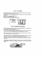
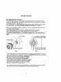
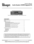
When the spn constmctio~ri s completed. cut back the 1-55'' dia, pvc receptacle flush with the Fpa wall finish or surface of deck. See Fig. 1.
Screw Mounting Adapter onto Spa-side Hemole, and finger-tighten. Do not use wrench.
Thread cable through conduit to low-voltage compmment of LX- 100 Powcr Ccntcr.
Carefully glue Mounting Adapter into I -U" pvc reccptaele using pvc cement. For aesthetic purposes, it is
suggested that the Spa-side Rcl~tolebe instiillcd with the red pushbutton in the 12 o'clock position. See
Fig. 2.
I-%" PCV PIPE
SWITCH I11 (REDWIRE)
H #2 (YELLOW WIRE)
SUPERSWITCH
M #3 (GREEN WIRE)
CH #4 (BLUEWIRE)
MOUNTING ADAPTER
Fig. I
Pig. 2
At the LX-100.identify h e 6-conductor cahll: from thc Spa-side Remote, and cut-off excess cable as necessary. Strip insulation of ench conductor ',4",and connect to REMOTE SWlTCHES Screw Terminnls
at bottom of circuit board in accordance with wiring diagram:
Black conductor (Swilch Common) LO GND screw terminal.
Red condk~ctor(Red Pushbuttan) to SPA screw terminal.
Yellow conductor (Yellow Pushbutton) to AUXI scrcw terminal.
Grecn conductor (Grrcn Pushbutton) to AUX2 scrtw terminal.
Blue conductor (Blue Pushbutton) to AUX3 scrcw terminal.
There is no connection for the orange conductor.
A set of adhesive labels is provided for custom identification of individual Spa-side Reniote pushbuttc~ns.
Use il pair nf fine-dp tweezcrs to carefully adhere thc appropriate label at each button.
POOL CLEANER
For s y ~ t c t iwlllch
i~
i~icorporirteiIhnoarcr pump p ( ~ ocleaner.
l
il i s posbibls to ildd a ~nech;rnic;~l
tiliic clock
for prugrunitnlag the di~ilydlcunil~gcyclch,
Inatall 24-flour Time Clock {model TMH-1.X) lnre L X - 100 f;~ceplntent the POOI, C1,EANER locat~on,
and plug rntu top of circuit b o i l d ikt CLNH TIMER socket, In accordance with instnlctions prov~dcd,
1nat;:H D 20-Amp Relay Kit (model R L Y - L X ) at the LX-100 Power Center in woordanre with instruc11unsprovided, und plug Into cIrcirIt board C L N R relay sockcl.
AUX1LIAHY VALVE
I t i s prr\sihle to t~ddilValve Actuator (model CVA-24) to rhc system to motorize a two-port or three-port
vnlvr: for it cualom hydraulic feetun. (silch ils n pool clermer, fountain, waterfall. etc.). The Valve Actuator
hc il~ttvi~tctl
rrt.\~lteithcr the pool cleilncr or ituxiliary 3 circuit.
C~II
Ktmuve knob, handle slid four screws rrorn cap o f valve to he motorized, and use the Ibur moilnling
\crew* prouidcct lo stollnt Velvc Actuator to valve. Run cabk to low-voltage compartnicnt of LX-100, and
plug intt9 circuit ho.~rtl111 A l l X VI,V Valve Socket,
ItIc~iliiylll~
I - p t n ~ t i ~Artif X VI,V Program Switch, whrch is located at bottom right of L,X-t(H) circuit
hoiird. i11td(IN thc curncr of il u r ~ i i l lsc.~wdrrv~.r
l
ot other blulit instrument to adjust !lie Swilch accordingly:
I To JCI~VJ~C V;IIVC
in3111 the pc>o1clenrier circuit, [urn Switch #1 ON and Switch #2 OFF.
2. 'To ;lrtlvatc valve fro111tlrr auxiliary 3 circuit, ltrnr Switch #I OFF iind Swltch #2 ON,
SPA WA'I'ERYALL CON'I'HOL,
Itor
systc~iiawlicre spa water Icvel 1s l~igllerthat1 that or the pool, it i s possiblc to use the sl~xiliary1 circuit
to roti~tethe return v i t l ~ eto ?iPilreturn poGtiun. {hub crciit~ng,111 ovcrtlow (watcrf;lll effect) Frt~rnlhe spa
I n f i r the pocrl, This featurc will cease whenevcr the spa i s being circulnted
7'0 rnnhlc this f ~ i ~ t i ti i ~s lacessary
,
l o ~tljustthe 7-position WTHPL-AUXl I'rognm Swiith, which i s
l o c i ~ t at
~ dccntcr right of LX-100 circuit boi~rd.t h e the corner elf a mill screwtlrivar or otlier blunt instruluc~itto \lrdc Switch #I and Switch 112 to the ON pmition.
FREEZE PROTECTION
A Rccircubting Freeze Serrsor (niodel FPS-C) mity he added l o the system. ft will protect thc p l r ~ ~ n h ~ n g
.at4 eqt~~pllle~tt
h111 ptrxaiblc f r e c ~ ed;i~ni~gc
hy runnlng the filler pump whenever the ternpereltitc fall\ to
'rpprnr. J IO F .
Insti111FPS-C III uccurd;lncc I\.1111 in~rructiun\provided, and connect to L X - 100 circuit board at FRZ and
GND +crew tcniiiltnls.
An Auxiliary Freeze Sctwor (model FPS-AUX) moy illso be i d d d to the system t uctivatc i t ~ ~ i l i ~ f y
eqiripnicnt (\itch as a jct pump) during potent~rtlfreez~ngconditions.
I n s d l FPS-AUX In ascordirnce with insiructians provided.
Note: I t is udvisitblc to inspccl and test Freeze Sensors at least once s year, preferably prior l o the
onset d thc freezing season. Testing can be done by immersing Sensor i n ice water.
SYSTEM START-UP
Apply power to t h s~yrtem.
At the Power Center, verify that the POWER ON sbtus light is illu~ninated,and make sun: that ;ill of thc
Service Switches are i n the "AUTO" position.
If the stitlus light is not on, check the J wrnp circuit brcokcr which is located abavc !he faceplate. I f the circuit breaker has tripped (indicated by i\ white tab), push to rcsct.
At the Indoor Controller, verify that there is a TEMPERATURE Display and check I h i ~rhc
l EQIIIPMENT STATUS INDICATORS are functioning when the IDushbuttonsare activated.
Irtheru i s no status display, check the connections at each end o f the communication cables very carefully.
If necessary, crimp new modular connectors to the cables.
I f the TEMPERATURE Display indicates three dashes (- - -) ar a very high temperature (400 dcgrces or
more), check tho connections to the Temperature Sensor,
At the Indoor Controller, press irppropriate Pwhbuttonfs) so ~hntnone of the EQUIIDMENTSTATUS
1NDlCATORS arc illuminated.
At the intake and Rclurn Vrrlvcs, Flip toggle switch on rear of A~Iui~tor(s)
between "ONI" i~nd"ON2"
positions as nicessary so that volvcs have rotated to pool circul;itinn.
At the Power Center, ver~fy[hut tho FILTER PUMP Time Clock is operitting.
To set the time of day, rotatc the dial in a clockwisc directiorr until the hours irnd ~ n i ~ ~ uline
t e sup w ~ t hthe
white amow at eight o'clock position on clock face.
To progmrn daily opcrzlting cycle(s), depress the desired numbcr of sections around the perilnt., r ~ l ll ~ c
dial by pushing towards the center. For each section depressed, the filter pump will oporute for 15 roinules.
If the system lias a POOL CLEANER Timc Clock, verify that i t i s operating, and check thi~tit also act!vates the filter pu~ripwhcn the FILTER PLJMPTimc Clock is not programmed on.
At the Power Center, slidc the SPA Service Switch to "FILL."1)KAIN" and hack to "AIlTO" posrlion,
and verify that the Valvc Actuators arc?rotating accordingly.
Ifone of the Valve Actuators is 180 degrees out of phase, flip toggle switch on rear o f Acltiator bctwcen
"ON1 " and "UN2" position,
At the Power Center, verify thirt the filter pump is being activated from the "QN" i ~ n d"OFF" posltlons or
the FILTER Service Switch.
Verify that thc auxiliary equipment is being activated fmm the "ON" and "OFF' posi~ionuoi' the AUXI,
AUX2 and AUX3 Service Switches.
Slide FlLTER Scrvica Switch to the "ON" position and the HEATER Service Switch to thc "SPA X!
POOL" position, and ver~fythat thc hratzr hiis fired.
I f the heatcr doesn't fin.. check the controls inside the healer and also the wiring conrtvctions.
At dio Powcr Ccnrcr, rcturn lho 11EATFaR Service Switch to tlic "SPA ONLY" position and all the other
Service Swilches to [he "BUTO" pcaition.
At thc Ind<~or
Contrullcr, prrbb Pushbuttan #S tcr turn rhr spa on.
Verify that the Valve Acluators have rotated to spi circulnt~on.rhc filter pump has been activated and the
heater ha5 fired.
Press P~shhultons#I. #2 und #3. end check that appropriate equipment i s being uctivnkd.
A set uf irdhesive I:tbcls is provided fur custom identification of equipmenl.
Usc ii pair of fine-tip tweezers to adhcn, the appmpriirte labcl(s) bclow the Pushhutton(s) on the Indoor
Controller.
Calihn~tiunof the I'KMPERATURE Display has k e n preset at the factory, However, fine adjustn~ent
con bt: accrrrnplihhcd i f necessary.
trrwrt il srni~ll1l;lt-blndc screwdrivur through thc ADJUST hale which IS Imucd hehind the right door of
Ihc Indoor C~~ermllcr.
ilnd totatu thc Ad-iustn~entScrew accordingly.
The system is now lrndy to bc operated as desired.
OWNER'S MANUAL
CP-100 POOL-SPA CONTROL SYSTEM
IMPORTANT SAFETY INSTRUCTIONS
When operating or servicing this electrical equipment. basic safety precautions shuuld always be obscwetl,
including the following:
READ AND FOLLOW ALL INSTRUCTIONS.
WARNING: To reduce the risk of injury, do not p n i t children to usc this product unless they are
closely supervised at all times.
SAVE THESE INSTRUCTIONS.
INTRODUCTION
The CP-100 is an electronic control system which is designed to coordinate and operate all of the equipment associuted with your swimming pool end spa.
The system is comprised of thrcc principle components:
I.Indoor Controller.
2. Power Center,
3. Motoriacd Valves (3qly).
The Controller provides pushbutton conlrol of the equipment from the convenience of your home; the
Power Center automatically controls the timing of your filter pump and pool cleaner (if i~pplicable)and
provides easy mnintennnce for your Pool Serviceperson; md the Motorized Valves switch the filter and
hestor froni pool to spa
Additionally, the Control Systeni incorporates ilnpctrcant safety features which protect your pool aluip.
ment from ;rccidental damage.
Y o i ~ syslern
r
may also include addirional Retnott: Controls end special options which further add to the
cnnvcniencu. siifety and economy of operating your pool equipment.
SAFETY FEATURES
HEATER PROTECTION
A built-in clwtrotiic delay circuit auromaticnlly runs the filter pump for an addi~ional5 mitlutes whcncvrr
the spa i s rumcd off. This feature enables the heater to cool down, so that the heal cxchunger and plumbing
are not diltlr~gedfmni ovcrhen~ing.
POOL CLEANER PROTECTION
I f your system incorporiites ctn :rutomatic pool cleaner, it will have lrecn plumbed i n conjunction with the
filter pump so that i t must have water circulation i n order to operate.
The CP-IOOincorporates lhc fi~llowingprotection features against possible pump damage i f them i s no
water circuln~ion:
I.
2.
The filter putnp will automntically be itctivited whenever thc pool cleaner is tunning. cven
if thc filter pun111 isn't programmed on.
Your pool cleaner will ai~tomaticdlybe switched off whenever water is being circulated to
the Spa.
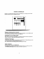
INDOOR CONTROLLER
Installed i n a convcnicnt location inside your house. the Conlroller gives you fingertip co~itrulof all the
equipment associated with your swimming pool and spa
Equipment Pushbuttons #S, #I, #2 and #3
Four Pushbuttons arc provided for activating the various pieces of cquipmenr. Your Pool Rtrildcr should
have custom-labeled each Pushbutton for your specific application.
EQUIPMENT STATUS INDICATORS
Slalus Lights are located a h v c each Pushbunon. The presence o f a light indicntcs that thc equipmenl is
running. The absence of a light indicates that equipmen! i s turned off-
TEMPEUTUR E Display
A digital display indicates the precise water temperature. Spa tempcritturc i c displayed during <pacic.culation, und pool temperature i s displayed during pool circulation.
Note: The filter pump must be running to provide accurate tempemlure display.
USING YOUR SPA
To turn your spa on. simply press Pushbutton 6.
The motorized valves will rotate to spacircularion, thc filter pump will turn on and the hcalrr will lire
The TEMPERATURE Display will let you know when the spi~i s ready for use.
POWER CENTER
Lnca~edin close proximity to your pool equipmc~rl,the Powcr Centtr housas mcchonical time clocks for
your filter pump trnd pool ciemer (if applicilble), and manual switches for your Pool Servicepenon.
FI1,TER PUMP and POOL C1,EANER Time Clocks
Check with your Pool Builder or Service Company as to the nmounl of tilnc rcquircd to proviclc efficient
filtraticm and cleaning of your pwl.
To set thc correct time of day, rotate the Dial(s) in a clockwise direc~ionu ~ ~ trhc
i l hours n ~ mirlules
~d
line
up wikh the white arrow at eight o'clock puskion on clock face.
Pny particular attention to the AM and PM sections of the Dialts).
To program the daily filtration or cleaning cyclc(s), depress the desired number of sections around tl\c
perimeter of the Dial(s) by pushing towards the center, For each sectio~rdzpwssud, the equipment will
operate for 15 minutes.
NOTE: A built-in protection circuit automalirally ndivates the filter pump whenever the pool
rlcaner Is running, even if the FILTER PUhIP Time Clock is not prograslmed on. This safegwrds
against pwiblc damage to the pool cleaner pump when there is no water circulation.
SPA Service Switch
fwr normal system opemtion, keep this Switch in the "AUTO" position.
The "FILL" and "BRAIN' positions we used when cleaning the spa,
FILTER Service Switch
For normal system operdtion keep this Switch in the "AUTO" position.
The ' D F F k d "ON" positions allow your Pool Serviceperson to ovorridc the FILTER PUMP Time
Clock without altering the program.
CAUTION: V your system incorporates s POOL CLEANER Time Clock, pump damage will occur
if the pool cleaner is activated while the FILTER Service Sw-itchis in the OFF position.
AUXP, AUX2 and AUX3 Service Switches
For normal system operation, keep these Switches in the "AUTO" position.
The "OFF' and " O N positions override the Indoor Controller, and provide convenient manual control at
the equipment site,
HEATER Switch
The "SPA ONLY" position will enable heating only when the spa is being circulated.
The "OW'position will disable the heater.
The "SPA & POOL" position will enable heating whenever the spa or pool is being circulated.
For Dual Thermoslat Heaters: At the heater set pool and spa lhenaoutatb:to desired temperatures. Verify
at the hater that the 3-position "ONIOFF' switch was set to "OFF' during installation.
For Single Thermostat Heaiers:To heat the spa only set the spa tempmature at the heater ilnd set the
LX- I00 PowerlLoad Center Heater swilch to "SPA ONLY". I pool heating is desired, it is necesslvy to
turn the heater thermostat down to pool temperature and set the LX-100 P o w e r b d Center Heater
switch to "SPA t 8001,".
Verify at the heater that the "ONIOFF' switch was set to " O N during installation.
The "SPA ONLY" position will enable heating only when the Spa is being circuloltad.
The "OFF position" will disable the heater.
The "SPA t POOL position" will enable heating whenever the filter pump is running.
PUMP DELAY Status Light
A built-in electronic delay circuit will autometically run the filter pump for an additional 4 minutes whenever the Spa is turned off. This enables the heater to cool down, so that the heat exchanger and plumbing
are not damaged from overheiiting.
The PUMP DELAY Light indicates that the delay is in effect.
POWER ON Status Light
Indicates that power has been connected to the system.
If this light is not on, consult your Pool Serviceperson.
MOTORIZED VALVES
Your control systeni i s designed to activate two motorized valves, which nuto~naticallymtite between pool
and spa circulation whenever Pushbutton #S (SPA) i s activated at the Indoor Controller. 'fhese valves are
also activated from the "FILL" and "DRAIN positions of the SPA Service Switch at the Power Center.
An additional motorized valve may have been installed for a custom hydraulic application, such as a fountain or waterfall, or (in lieu of a booster pump) to activate your pool cleaner.
A toggle switch is located on the war o f each Valve Actuator. This switch is used by the Pool Builder to
on
set the correct valve r ~ t i ~ t i direction.
DO NOT ADJUST THIS SWITCH POSITION.
SYSTEM OPTIONS
SPA-SIDE REMOTE CONTROL
A 4-button waterproof Remote Control may have k e n installed into the wall of your spil, This will cnable
you ta control the equipment while sitting in your spa.
Your Pool Builder should have cuslom-hbeled each button for your specific nppliea~ion.
The RED Button duplicates Pushbutton #S at Lhe Indoor Controller (acrivales Lhe spa circulation).
The YELLOW Button duplicates Pushbutton #I at the Indoor ControlIcr.
The GREEN Button duplicates Pushbunon #Z nt h e lndour Controller,
The BLUE Button duplicates fishbutton #3 at rht. Indoor Controller.
SPA WATERFALL CONTROI,
If your spa wrrter level i s elevated above that of the pool, your Pool Builder may have incorpnratcd it spa
waterfall (spillway) feiature.
With this feature, you can use Pushbutton#l at the tndoor Controller (aid the YELLOW Button at 1hc
Spa-side Hemole) to circulate the pool water back to the spa, creating an overflow (waterfall effect) fr01n
the spa to the pool. Tllr waterfall effect will cease whenever yon are circulating the spn.
FREEZE PROTECTION
A Freeze Sensor may have been added to your Control System. Tiris will proteck the plumbing and equipment froin frcczr damage by running the filter pump whenever the ternpenlure falls l o apprvx. 41"F.
Frrsze Sensors may have also k e n added lo activate auxiliary equip~nent(such as a jut pump or ~ountain)
during potential freezing condidons.
MAINTENANCE
CLEANING THE SPA
For cleaning or maintenance purposes, it is possible to use the Control System to automatically empty your
Spa and then to refill with clcan water from the Pool.
At the Power Center:
I.
2.
3.
4.
5.
Set the SPA Service Switch to " D W " position.
Set the FILTER Service Switch to Ihe "OW position. The Spa will begin to drain into
the Pool.
Before the Spa has completely drained, set the FILTER Service Switch to the " O W
position. Do not drain the Spa completely or prime will be lost.
When cleaning or spa maintenance is complete, set the SPA Service Switch to the "FILL"
position and thc FUITER Service Switch to Ihe "ON" position, The Spa will begin to fill
with clean water from the Pool.
When the waler level in the Spa has returned to normal, return thc SPA Sewice Switch
and the FILTER Service Switch to the "AUTO" pos~tion.
CAUTION: Do not lcavo the equipment unattended when draining or filling the Spa.
WINTERIZING THE SYSTEM
During Ihe winter season, it is possible to partially drain your Swimming Pool and disable the pan1 equipment, but still be ablr?to use your Spa.
Consult a qualified Servict: Company to drain the Pool and protect the plumbing froin freeze damage.
The following procedure will disable the pool equipment:
f,
2.
3.
4.
At the Indoor Contrallcr, press Pushbutton #S (to turn he Spa on).
At the motorized valves. flip toggle switch on rear of Valve Actuators to the "OFF
position,
At thc Indoor Controller. press Pushbutton #S (to turn the Spa off).
At the Power Center, set the FILTER Service Swilch to the "OFF"position (to disable
the Time Clock) or, if daily Spa filtration is m q u i ~ dleave
,
the FILTER Scrvlce Switch in
the "AUTO" position and program rho FILTER PUMP Tlme Clock accordingly.
If your Control System incorporates a Recirculating Freeze Sensor, it may not be necessary to have the
Swi~niningPool drained. It is however mcommcnded that all Freeze Sensors be tested by an authorized
Scrviccperson before the onset of the winter season.
Testing can be accomplished by placing the Sensor in a glass of ice water, and tunling the
FILTER Service Switch to the "OFF" posilion. If the Sensor i s functioning carrcctly, the filter pump
should turn on within [cn minutes. This test should also be conducted on any Auxiliary Freeze Sensors
which may have k e n added for the jet pump or auxiliary equipment.
TROUBLE-SHOOTING
Your Control System is designed to provide y e w of trouble-free pool and spa cnjoymcn1. Howcver, i T a1
any time your System should behave erndcally, consult the fallowing Check List, which should hclp to
alleviate any problems caused by operator error. If you are sdll unuble to solve your pwtictllar symptom,
wfer the situation to a qualified Pool Service Company.
GENERAL
1.
2.
Check all circuit breakers at elecrrical sub-panel.
At the Power Center. ensure that all the Servfte Switcbes are in the "AIJTO" position.
NOTHING QPERATES
I.
2.
Check 3-amp circuit brcllker which is located above FILTER PUMP TLmc Clock in
Power Center. Tripped circuit breaker is indicated by a white ub. Push to reset.
If circuit b ~ p k e continues
r
to trip, refer to a qualified Service Company.
FILTER PUMP DOES NOT QPERATE
I.
At the Power Center, check that the FILTER PUMP Time Clock is programmed on.
2.
Turn the FlLTER Service Switch to the "ON" position. I f the pump still doesn't opentc,
consult a qualified Service Company.
FILTER PUMP DOES NOT TURN OFF
1.
2.
3.
4.
At the Power Center, check that thc FILTER Service Switch is no1 in the "ON" position.
Check that tho PUMP BELAY Status Lighl is not on, indicating that the System is
~ n n i n gits 4-minute cool down cycle.
Check thnt the POOL CLEANER Time Clock is not programtned on, nutomatically
forcing the filter pump on.
Turn the FfLTER Service Switch to the "OFF"pnsidan, If the pump csntinucs to run,
consult a qualified Service Company.
POOL CLEANER DOES NOT QPERATE
1.
2.
3.
At rhs Power Cenrer, chcck that the POOL CLEANER Ttme Clock is programtned on.
At the Indoor Controller, make suro that Pushbutton #S (SPA) i s not turnsd on.
Pool cleaner pump may require servicing.
mATEH DOES NOT OPERATE
I.
2.
3.
4,
Make sun that film pump is running.
Check heater thermostat setting and pilot light (if applicable).
Check filter p m s s u ~ .If filter is clogged. thc heater may not br: getling sufficient water
flow.
Heater may q u i r e servicing.
SPA WATER LEVEL DROPS
I.
2.
3.
At the Power Cenrer, check that the SPA Service Switch i s in the " A U T O position.
Check that Motorized Valves rotate in both directions by adjusting toggle switch on the
rear of each Valve Actuators. Remember to return switches Ia their original position after
testing.
A "check valve" in the system may be leaking. Refer to a qualified Service Company,
For questions, rcpairs. replacement pam, or informatinn on pussiblc AulhnriWd Service Centers within your
vicinity call:
-
Peatair Pool Products 800-831-7133
Or visit us on the Internet nt w w w . p e n ~ l . c o m
Because ~ I i f y m a n o most
m
PIN 94 I II)??