1
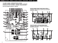
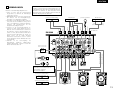
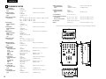
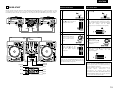
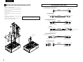
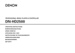
DJ MIXER / DJ 混音台
DN-X300
OPERATING INSTRUCTIONS
BEDIENUNGSANLEITUNG
MODE D’EMPLOI
ISTRUZIONI PER L’USO
INSTRUCCIONES DE OPERACION
GEBRUIKSAANWIJZING
BRUKSANVISNING
操作說明書
FOR ENGLISH READERS
FÜR DEUTSCHE LESER
POUR LES LECTEURS FRANCAIS
PER IL LETTORE ITALIANO
PARA LECTORES DE ESPAÑOL
VOOR NEDERLANDSTALIGE LEZERS
FOR SVENSKA LÄSARE
中
文
PAGE
5
SEITE
11
PAGE
17
PAGINA 23
PAGINA 29
PAGINA 35
SIDA
41
第 47 頁
~
~
~
~
~
~
~
~
PAGE
10
SEITE
16
PAGE
22
PAGINA 28
PAGINA 34
PAGINA 40
SIDA
46
第 53 頁
SAFETY INSTRUCTIONS
CAUTION
1.
Read Instructions – All the safety and operating instructions
should be read before the product is operated.
2.
Retain Instructions – The safety and operating instructions
should be retained for future reference.
3.
Heed Warnings – All warnings on the product and in the
operating instructions should be adhered to.
4.
Follow Instructions – All operating and use instructions
should be followed.
5.
Cleaning – Unplug this product from the wall outlet before
cleaning. Do not use liquid cleaners or aerosol cleaners.
The lightning flash with arrowhead symbol, within an equilateral triangle, is intended to
alert the user to the presence of uninsulated “dangerous voltage” within the product’s
enclosure that may be of sufficient magnitude to constitute a risk of electric shock to
persons.
6.
Attachments – Do not use attachments not recommended
by the product manufacturer as they may cause hazards.
7.
Water and Moisture – Do not use this product near water –
for example, near a bath tub, wash bowl, kitchen sink, or
laundry tub; in a wet basement; or near a swimming pool;
and the like.
The exclamation point within an equilateral triangle is intended to alert the user to the
presence of important operating and maintenance (servicing) instructions in the literature
accompanying the appliance.
8.
Accessories – Do not place this product on an unstable cart,
stand, tripod, bracket, or table. The product may fall,
causing serious injury to a child or adult, and serious
damage to the product. Use only with a cart, stand, tripod,
bracket, or table recommended by the manufacturer, or
sold with the product. Any mounting of the product should
follow the manufacturer’s instructions, and should use a
mounting accessory
recommended by the
manufacturer.
RISK OF ELECTRIC SHOCK
DO NOT OPEN
CAUTION: TO REDUCE THE RISK OF ELECTRIC SHOCK, DO NOT REMOVE COVER (OR
BACK). NO USER SERVICEABLE PARTS INSIDE. REFER SERVICING TO
QUALIFIED SERVICE PESONNEL.
WARNING: TO
PREVENT FIRE OR SHOCK HAZARD, DO NOT EXPOSE THIS
APPLIANCE TO RAIN OR MOISTURE.
9.
CAUTION:
LABELS:
1. Handle the power supply cord carefully
Do not damage or deform the power supply cord. If it
is damaged or deformed, it may cause electric shock
or malfunction when used. When removing from wall
outlet, be sure to remove by holding the plug
attachment and not by pulling the cord.
2. Do not open the top cover
In order to prevent electric shock, do not open the top
cover.
If problems occur, contact your DENON dealer.
3. Do not place anything inside
Do not place metal objects or spill liquid inside the DJ
mixer.
Electric shock or malfunction may result.
Please, record and retain the Model name and serial
number of your set shown on the rating label.
Model No. DN-X300
Serial No.
CAUTION
TO PREVENT ELECTRIC SHOCK, MATCH
WIDE BLADE OF PLUG TO WIDE SLOT,
FULLY INSERT.
ATTENTION
POUR ÉVITER LES CHOCS ÉLECTRIQUES,
INTERODUIRE LA LAME LA PLUS LARGE
DE LA FICHE DANS LA BORNE
CORRESPONDANTE DE LA PRISE ET
POUSSER JUSQU’ AU FOND.
A product and cart
combination should be
moved with care. Quick
stops, excessive force,
and uneven surfaces may
cause the product and cart
combination to overturn.
11. Power Sources – This product should be operated only
from the type of power source indicated on the marking
label. If you are not sure of the type of power supply to
your home, consult your product dealer or local power
company. For products intended to operate from battery
power, or other sources, refer to the operating instructions.
12. Grounding or Polarization – This product may be equipped
with a polarized alternating-current line plug (a plug having
one blade wider than the other). This plug will fit into the
power outlet only one way. This is a safety feature. If you
are unable to insert the plug fully into the outlet, try
reversing the plug. If the plug should still fail to fit, contact
your electrician to replace your obsolete outlet. Do not
defeat the safety purpose of the polarized plug.
ANTENNA
LEAD IN
WIRE
GROUND
CLAMP
ANTENNA
DISCHARGE UNIT
(NEC SECTION 810-20)
ELECTRIC
SERVICE
EQUIPMENT
GROUNDING CONDUCTORS
(NEC SECTION 810-21)
GROUND CLAMPS
POWER SERVICE GROUNDING
ELECTRODE SYSTEM
(NEC ART 250, PART H)
NEC - NATIONAL ELECTRICAL CODE
15. Outdoor Antenna Grounding – If an outside antenna or
cable system is connected to the product, be sure the
antenna or cable system is grounded so as to provide some
protection against voltage surges and built-up static
charges. Article 810 of the National Electrical Code,
ANSI/NFPA 70, provides information with regard to proper
grounding of the mast and supporting structure, grounding
of the lead-in wire to an antenna discharge unit, size of
grounding conductors, location of antenna-discharge unit,
connection to grounding electrodes, and requirements for
the grounding electrode. See Figure A.
16. Lightning – For added protection for this product during a
lightning storm, or when it is left unattended and unused
for long periods of time, unplug it from the wall outlet and
disconnect the antenna or cable system. This will prevent
damage to the product due to lightning and power-line
surges.
17. Power Lines – An outside antenna system should not be
located in the vicinity of overhead power lines or other
electric light or power circuits, or where it can fall into such
power lines or circuits. When installing an outside antenna
system, extreme care should be taken to keep from
touching such power lines or circuits as contact with them
might be fatal.
18. Overloading – Do not overload wall outlets, extension
cords, or integral convenience receptacles as this can result
in a risk of fire or electric shock.
10. Ventilation – Slots and openings in the cabinet are provided
for ventilation and to ensure reliable operation of the
product and to protect it from overheating, and these
openings must not be blocked or covered. The openings
should never be blocked by placing the product on a bed,
sofa, rug, or other similar surface. This product should not
be placed in a built-in installation such as a bookcase or rack
unless proper ventilation is provided or the manufacturer’s
instructions have been adhered to.
FIGURE A
EXAMPLE OF ANTENNA GROUNDING
AS PER NATIONAL
ELECTRICAL CODE
13. Power-Cord Protection – Power-supply cords should be
routed so that they are not likely to be walked on or pinched
by items placed upon or against them, paying particular
attention to cords at plugs, convenience receptacles, and
the point where they exit from the product.
19. Object and Liquid Entry – Never push objects of any kind
into this product through openings as they may touch
dangerous voltage points or short-out parts that could
result in a fire or electric shock. Never spill liquid of any
kind on the product.
20. Servicing – Do not attempt to service this product yourself
as opening or removing covers may expose you to
dangerous voltage or other hazards. Refer all servicing to
qualified service personnel.
21. Damage Requiring Service – Unplug this product from the
wall outlet and refer servicing to qualified service personnel
under the following conditions:
a) When the power-supply cord or plug is damaged,
b) If liquid has been spilled, or objects have fallen into the
product,
c) If the product has been exposed to rain or water,
d) If the product does not operate normally by following
the operating instructions. Adjust only those controls
that are covered by the operating instructions as an
improper adjustment of other controls may result in
damage and will often require extensive work by a
qualified technician to restore the product to its normal
operation,
e) If the product has been dropped or damaged in any way,
and
f) When the product exhibits a distinct change in
performance – this indicates a need for service.
22. Replacement Parts – When replacement parts are required,
be sure the service technician has used replacement parts
specified by the manufacturer or have the same
characteristics as the original part.
Unauthorized
substitutions may result in fire, electric shock, or other
hazards.
23. Safety Check – Upon completion of any service or repairs
to this product, ask the service technician to perform safety
checks to determine that the product is in proper operating
condition.
24. Wall or Ceiling Mounting – The product should be mounted
to a wall or ceiling only as recommended by the
manufacturer.
25. Heat – The product should be situated away from heat
sources such as radiators, heat registers, stoves, or other
products (including amplifiers) that produce heat.
2
ENGLISH DEUTSCH
FRANÇAIS
ITALIANO
ESPAÑOL
NEDERLANDS
SVENSKA
TOP PANEL DIAGRAM / OBERES BEDIENFELD-SCHEMA /
SCHEMA DU PANNEAU SUPERIEUR / SCHEMA PANNELLO SUPERIORE/
DIAGRAMA DEL PANEL SUPERIOR / OVERZICHT VAN BOVENPANEEL /
BILD ÖVER ÖVERSTA PANELEN / 頂面板視圖
REAR PANEL DIAGRAM / HINTERES ANSCHLUSSFELD-SCHEMA /
SCHEMA DU PANNEAU ARRIERE / SCHEMA PANNELLO POSTERIORE /
DIAGRAMA DEL PANEL POSTERIOR / OVERZICHT VAN ACHTERPANEEL /
BAKPANELEN / 後面板視圖
t yu i o !0!0 o i !1 y t
r
!2
e
!3
@4
@5
@6
@7 @8
!4
w
!5
q
!6
!7
!7
!8
!9
!9
@0
@1
#7 #6 #5 #4 #3 #2 #1 #0 #3 #2 #1 #0
@9
FRONT PANEL DIAGRAM / VORDERES BEDIENFELD-SCHEMA /
SCHEMA DU PANNEAU AVANT / SCHEMA PANNEAU AVANT /
DIAGRAMA DEL PANEL FRONTAL / OVERZICHT VAN VOORPANEEL /
FRONTPANELEN / 前面板視圖
#8
#9
$2
$1 $4
#9
#8
@1
@2
@3
3
$3 $2
$1
$0
NOTE ON USE / HINWEISE ZUM GEBRAUCH /
OBSERVATIONS RELATIVES A L’UTILISATION / NOTE SULL’USO
NOTAS SOBRE EL USO / ALVORENS TE GEBRUIKEN / OBSERVERA
• Avoid high temperatures.
Allow for sufficient heat dispersion when
installed on a rack.
• Vermeiden Sie hohe Temperaturen.
Beachten Sie, daß eine ausreichend
Luftzirkulation gewährleistet wird, wenn das
Gerät auf ein Regal gestellt wird.
• Eviter des températures élevées
Tenir compte d’une dispersion de chaleur
suffisante lors de l’installation sur une
étagère.
• Evitate di esporre l’unità a temperature alte.
Assicuratevi che ci sia un’adeguata
dispersione del calore quando installate
l’unità in un mobile per componenti audio.
• Evite altas temperaturas
Permite la suficiente dispersión del calor
cuando está instalado en la consola.
• Vermijd hoge temperaturen.
Zorg voor een degelijk hitteafvoer indien het
apparaat op een rek wordt geplaatst.
• Undvik höga temperaturer.
Se till att det finns möjlighet till god
värmeavledning vid montering i ett rack.
• Handle the power cord carefully.
Hold the plug when unplugging the cord.
• Gehen Sie vorsichtig mit dem Netzkabel um.
Halten Sie das Kabel am Stecker, wenn Sie
den Stecker herausziehen.
• Manipuler le cordon d’alimentation avec
précaution.
Tenir la prise lors du débranchement du
cordon.
• Manneggiate il filo di alimentazione con cura.
Agite per la spina quando scollegate il cavo
dalla presa.
• Maneje el cordón de energía con cuidado.
Sostenga el enchufe cuando desconecte el
cordón de energía.
• Hanteer het netsnoer voorzichtig.
Houd het snoer bij de stekker vast wanneer
deze moet worden aan- of losgekoppeld.
• Hantera nätkabeln varsamt.
Håll i kabeln när den kopplas från el-uttaget.
• Keep the set free from moisture, water, and
dust.
• Halten Sie das Gerät von Feuchtigkeit,
Wasser und Staub fern.
• Protéger l’appareil contre l’humidité, l’eau et
lapoussière.
• Tenete l’unità lontana dall’umidità, dall’acqua
e dalla polvere.
• Mantenga el equipo libre de humedad, agua
y polvo.
• Laat geen vochtigheid, water of stof in het
apparaat binnendringen.
• Utsätt inte apparaten för fukt, vatten och
damm.
• Unplug the power cord when not using the
set for long periods of time.
• Wenn das Gerät eine längere Zeit nicht
verwendet werden soll, trennen Sie das
Netzkabel vom Netzstecker.
• Débrancher le cordon d’alimentation lorsque
l’appareil n’est pas utilisé pendant de
longues périodes.
• Disinnestate il filo di alimentazione quando
avete l’intenzione di non usare il filo di
alimentazione per un lungo periodo di tempo.
• Desconecte el cordón de energía cuando no
utilice el equipo por mucho tiempo.
• Neem altijd het netsnoer uit het stopkontakt
wanneer het apparaat gedurende een lange
periode niet wordt gebruikt.
• Koppla ur nätkabeln om apparaten inte
kommer att användas i lång tid.
✽ (For sets with ventilation holes)
• Do not obstruct the ventilation holes.
• Die Belüftungsöffnungen dürfen nicht
verdeckt werden.
• Ne pas obstruer les trous d’aération.
• Non coprite i fori di ventilazione.
• No obstruya los orificios de ventilación.
• De ventilatieopeningen mogen niet worden
beblokkeerd.
• Täpp inte till ventilationsöppningarna.
CAUTION
• The ventilation should not be impeded by covering the
ventilation openings with items, such as newspapers,
table-cloths, curtains, etc.
• No naked flame sources, such as lighted candles,
should be placed on the apparatus.
4
• Do not let foreign objects in the set.
• Keine fremden Gegenstände in das Gerät
kommen lassen.
• Ne pas laisser des objets étrangers dans
l’appareil.
• E’ importante che nessun oggetto è inserito
all’interno dell’unità.
• No deje objetos extraños dentro del equipo.
• Laat geen vreemde voorwerpen in dit
apparaat vallen.
• Se till att främmande föremål inte tränger in i
apparaten.
• Do not let insecticides, benzene, and thinner
come in contact with the set.
• Lassen Sie das Gerät nicht mit Insektiziden,
Benzin
oder
Verdünnungsmitteln
in
Berührung kommen.
• Ne pas mettre en contact des insecticides,
du benzène et un diluant avec l’appareil.
• Assicuratevvi che l’unità non venga in
contatto con insetticidi, benzolo o solventi.
• No permita el contacto de insecticidas,
gasolina y diluyentes con el equipo.
• Laat geen insektenverdelgende middelen,
benzine of verfverdunner met dit apparaat in
kontakt komen.
• Se till att inte insektsmedel på spraybruk,
bensen och thinner kommer i kontakt med
apparatens hölje.
• DECLARATION OF CONFORMITY
We declare under our sole responsibility that this
product, to which this declaration relates, is in
conformity with the following standards:
EN60065, EN55013, EN55020, EN61000-3-2 and
EN61000-3-3.
Following the provisions of 73/23/EEC,
89/336/EEC and 93/68/EEC Directive.
• ÜBEREINSTIMMUNGSERKLÄRUNG
Wir erklären unter unserer Verantwortung, daß
dieses Produkt, auf das sich diese Erklärung
bezieht, den folgenden Standards entspricht:
EN60065, EN55013, EN55020, EN61000-3-2 und
EN61000-3-3.
Entspricht den Verordnungen der Direktive
73/23/EEC, 89/336/EEC und 93/68/EEC.
• DECLARATION DE CONFORMITE
Nous déclarons sous notre seule responsabilité
que l’appareil, auquel se réfère cette déclaration,
est conforme aux standards suivants:
EN60065, EN55013, EN55020, EN61000-3-2 et
EN61000-3-3.
D’après les dispositions de la Directive
73/23/EEC, 89/336/EEC et 93/68/EEC.
• DICHIARAZIONE DI CONFORMITÀ
Dichiariamo con piena responsabilità che questo
prodotto, al quale la nostra dichiarazione si
riferisce, è conforme alle seguenti normative:
EN60065, EN55013, EN55020, EN61000-3-2 e
EN61000-3-3.
In conformità con le condizioni delle direttive
73/23/EEC, 89/336/EEC e 93/68/EEC.
QUESTO PRODOTTO E’ CONFORME
AL D.M. 28/08/95 N. 548
• DECLARACIÓN DE CONFORMIDAD
Declaramos
bajo
nuestra
exclusiva
responsabilidad que este producto al que hace
referencia esta declaración, está conforme con
los siguientes estándares:
EN60065, EN55013, EN55020, EN61000-3-2 y
EN61000-3-3.
Siguiendo las provisiones de las Directivas
73/23/EEC, 89/336/EEC y 93/68/EEC.
• EENVORMIGHEIDSVERKLARING
Wij
verklaren
uitsluitend
op
onze
verantwoordelijkheid dat dit produkt, waarop
deze
verklaring
betrekking
heeft,
in
overeenstemming is met de volgende normen:
EN60065, EN55013, EN55020, EN61000-3-2 en
EN61000-3-3.
Volgens de bepalingen van de Richtlijnen
73/23/EEC, 89/336/EEC en 93/68/EEC.
• ÖVERENSSTÄMMELSESINTYG
Härmed intygas helt på eget ansvar att denna
produkt, vilken detta intyg avser, uppfyller
följande standarder:
EN60065, EN55013, EN55020, EN61000-3-2 och
EN61000-3-3.
Enligt stadgarna i direktiv 73/23/EEC, 89/336/EEC
och 93/68/EEC.
FCC INFORMATION (For US customers)
• Never disassemble or modify the set in any
way.
• Versuchen Sie niemals das Gerät
auseinander zu nehmen oder auf jegliche Art
zu verändern.
• Ne jamais démonter ou modifier l’appareil
d’une manière ou d’une autre.
• Non smontate mai, nè modificate l’unità in
nessun modo.
• Nunca desarme o modifique el equipo de
ninguna manera.
• Nooit dit apparaat demonteren of op andere
wijze modifiëren.
• Ta inte isär apparaten och försök inte bygga
om den.
• Please be care the environmental aspects of battery
disposal.
• The apparatus shall not be exposed to dripping or
splashing for use.
• No objects filled with liquids, such as vases, shall be
placed on the apparatus.
1. PRODUCT
3. NOTE
This product complies with Part 15 of the
FCC Rules. Operation is subject to the
following two conditions: (1) this product
may not cause harmful interference, and (2)
this product must accept any interference
received, including interference that may
cause undesired operation.
This product has been tested and found to comply with the limits for
a Class B digital device, pursuant to Part 15 of the FCC Rules. These
limits are designed to provide reasonable protection against harmful
interference in a residential installation.
This product generates, uses and can radiate radio frequency energy
and, if not installed and used in accordance with the instructions, may
cause harmful interference to radio communications. However, there
is no guarantee that interference will not occur in a particular
installation. If this product does cause harmful interference to radio or
television reception, which can be determined by turning the product
OFF and ON, the user is encouraged to try to correct the interference
by one or more of the following measures:
• Reorient or relocate the receiving antenna.
• Increase the separation between the equipment and receiver.
• Connect the product into an outlet on a circuit different from that
to which the receiver is connected.
• Consult the local retailer authorized to distribute this type of
product or an experienced radio/TV technician for help.
2. IMPORTANT NOTICE:
DO NOT MODIFY THIS PRODUCT
This product, when installed as indicated in
the instructions contained in this manual,
meets FCC requirements. Modification not
expressly approved by DENON may void
your authority, granted by the FCC, to use
the product.
ENGLISH
2 INTRODUCTION
2 PART NAMES AND FUNCTIONS
Thank you very much for purchasing the DENON DN-X300 DJ MIXER.
DENON proudly presents this advanced DJ MIXER to audiophiles and music lovers as a further proof of DENON’s
non-compromising pursuit of the ultimate in sound quality. The high quality performance and easy operation are
certain to provide you with many hours of outstanding listening pleasure.
(1) Top panel
– TABLE OF CONTENTS –
z
x
c
MAIN FEATURES ...............................................5
PART NAMES AND FUNCTIONS ...................5, 6
CONNECTIONS ..................................................7
2 ACCESSORIES
Please check to make sure the following items
are included with the main unit in the carton:
v
b
n
SPECIFICATIONS................................................8
FADER START ....................................................9
ROTATING INPUT SELECT SWITCHES ...........10
w MIC EQ controls
• Contour the frequency response of the MIC
input –12 dB to +12 dB.
• At the center position, sound is flat.
• Adjusts the level of Mic signal.
r AUX INPUT control
• Adjusts the level of AUX input.
• This input is mixed after the Crossfader and
EFFECT LOOP.
t Source EQ controls
02. VCA controlled Channel Fader and Crossfader
06. Channel Reverse function
This function allows the left hand channel fader or
right hand channel fader to control PGM1 or
PGM2.
03. Channel Fader and Crossfader curve adjustable
This feature allows adjusting the “shape” of the
Crossfader and Channel fader response from a
gentle curve for smooth to the steep pitch
required for top performance cut and scratch
effects.
07. Enhanced Input/Output terminals
4 LINE, 2 PHONO, 1 AUX, 1 Microphone systems,
2 MASTER outputs and 1 BOOTH output are
provided independently. Effect SEND/RETURN
terminals are also provided for a external effects
processor.
04. Channel Fader and Crossfader Reverse
08. 3-Band equalizer/gain
LOW, MID, HI and GAIN controls are available on
every input channel.
05. Channel Fader and Crossfader Start
The CD player can be started or stopped simply by
increasing or decreasing the level of the Ch. fader
or by using the Crossfader left to right or right to
left. (This function can only be used when the
DENON CD players DN-S3000, DN-S5000, DNS1000 or etc. is connected to the DN-X300.)
• When TALKOVER is selected , all signals except
the microphone level are decreased by 20 dB.
When at the ON or OFF position all signals
remain at their standard levels.
e MIC LEVEL control
q Operating instructions.......................................1
w AC adaptor ........................................................1
(AA-26 : for AC 120 V, AA-27 : for AC 230 V)
1 MAIN FEATURES
01. Penny & Giles Crossfader
Smooth and reliable mixing is excelled by Penny &
Giles Crossfader.
q MIC ON/OFF/TALKOVER switch
09. 3-Band Equalizer Kill function
10. 8 direction placement for input selector
11. Microphone Talkover function
• Contour the frequency response of the selected
inputs.
HI and MID:
• Adjusts the high-tone and mid-tone sound –40
dB to +10 dB.
LOW:
• Adjusts the low-tone sound –40 dB to +6 dB.
NOTE:
Clipping may occur if adjustments are set to
harsh.
y GAIN control
• Adjusts the gain of each input channel.
u EFFECT LOOP WET/DRY control
• Use this to adjust the ratio of original and
effected sound.
i EQ ON/OFF button
• When the LED is lit, EQ is ON. Otherwise EQ is
bypassed.
o PGM BALANCE control
• Adjusts the L/R balance of the PGM input.
(Refer to page 3.)
!0 EFFECT LOOP ON/OFF switch
• Routes the assigned signal through the external
processor attached to the SEND/RETURN
connectors on the rear.
• When the EFFECT LOOP is ON, the LED is lit.
(When the external processor isn’t connected,
the LED will blink.)
!1 CH REVERSE button
• This switch allows the left hand fader or right
hand fader to control PGM1 or PGM2.
• When the CH REVERSE mode is ON, the CH1
fader will be able to control PGM 2 sound and
the CH2 fader will be able to control PGM 1
sound.
NOTE:
Please don’t confuse with the CH 1/2 FADER
REVERSE switch $4.
!2 MASTER LEVEL control
• Adjust the level of the MASTER outputs.
!3 BOOTH OUTPUT control
• Adjusts the level of BOOTH output.
!4 CUE SELECT switch
• This switch is used to select the signal for CUE.
Selected CUE sound will send to the
headphone.
!5 Headphone PAN control
• This function allows you to monitor the CUE
level as well as the MASTER output in your
headphones. A CUE Level may only be
monitored of the CUE signal is selected.
• Serves two purposes…In the STEREO mode it
changes the relative levels of the CUE and
MASTER mixed together in both ear cups. In
the SPLIT CUE mode it changes the balance
between the monaural CUE sound in the left
and monaural MASTER sound in the right.
!6 PHONES LEVEL control
• Adjusts the headphone output level.
5
ENGLISH
!7 Input select switch
• Switches between the PHONO/LINE and LINE
inputs.
• When the lever of switch is vertical position, the
LINE2 or LINE4 input is selected.
• When the lever of switch is slope, the
PHONO1/LINE1 or PHONO2/lINE3 input is
selected.
• You can perform 8 direction placement. See
page 10.
!8 SPLIT CUE button
• In the STEREO mode, the stereo sound of
MASTER and CUE are fed to both ear cups. In
the SPLIT CUE mode, the headphone circuit
provides monaural CUE sound to the left and
monaural MASTER sound to the right.
• When the Level Meter mode select switch is
set to “MASTER”…In the STEREO mode, the
meter indicates the stereo level in the L/R
Master output. In the SPLIT CUE mode, the
monaural CUE sound level is displayed on the
left and the monaural MASTER sound level is
displayed on the right.
• In the SPLIT CUE mode, the LED is lit.
!9 PGM 1/2 KILLS switches
• These switches are used cut out the Treble, Mid
or Bass frequencies of the incoming audio
signal. When these switches moved up or
down, the selected frequency level is cut, the
LED located directly above the specific switch
will glow indicating the cut function has been
activated.
@0 Level meter mode select switch
• The position of this switch will determine the
Level Meter mode. In the “MASTER” position,
the meter will detail the out level of the left and
right channels. In the “PGM 1/2” position, the
left side of the meter will indicate monaural
level of the PGM 1 and the right side of the
meter will indicate monaural level of the PGM 2.
@1 Channel Fader
• Controls the channel output level.
@2 Level meter
• The dual LED's indicators are used to detail
either the master output level, a combination of
the master output level and the CUE signal
level, or the PGM1/2 monaural level.
@3 Crossfader
• Fades the overall mixer output between
channels 1 and 2.
6
(2) Rear panel
@4 Power operation switch (POWER)
• Selects power “ON” or “OFF”.
NOTE:
Whenever the power switch is in the OFF state,
the AC adaptor is still connected on AC line
voltage. Please be sure to unplug the cord when
you don’t use for along time.
@5 BALANCED MASTER OUT jacks
• These 1/4” TRS jacks provide a balanced line
level output.
• Connect these jacks to the balanced analog
input jacks on an amplifier or console.
• Pin layout: Tip=Hot Ring=Cold Sleeve=GND
@6 EFFECT LOOP SEND/RETURN jacks
• These 1/4” TS stereo jacks allow external
processing of the program signal.
• When connect monaural type effect processor,
use Lch input and output.
@7 MIC BALANCED INPUT jack
• Accepts an balanced microphone with 1/4” TRS
mono jacks.
• Pin layout: Tip=Hot Ring=Cold Sleeve=GND
@8 MIC EFFECT LOOP jack
• These 1/4” TRS jack allow external processing
of the program signal.
• Pin layout:
Tip=SEND Ring=RETURN Sleeve=GND
@9 PGM1, 2 FADER output jacks
• Connect these jacks to the FADER input jacks of
DN-S3000, DN-S5000, DN-S1000 and etc. using
the 3.5mm stereo mini cord.
#0 Phono ground screw (GND)
• This screws provide a place to connect the
ground wire from a turntable.
• This terminal is exclusively for a turntable
ground and not a safety earth ground.
#1 PHONO1, 2 / LINE1, 3 switches
(LN / PH)
• These switches change the input from PHONO
to a LINE level input.
• These switches set a LINE level input when
turntable is not connected.
NOTE:
Always be sure main power is shut off before
change the position of the Line Level Selector
Switch.
(3) Front panel
#2 PHONO1, 2 / LINE1, 3 input jacks
• These stereo pairs of unbalanced RCA jacks are
inputs for a PHONO (RIAA) stage for magnetic
(MM) cartridges or a LINE stage suitable for any
device, such as a CD player.
#3 LINE2, 4 input jacks
• These stereo pairs of unbalanced RCA jacks are
inputs for any line level device.
#4 AUX INPUT jacks
• This stereo pair of RCA jacks provides an
unbalanced line level input with independent top
panel AUX INPUT control.
• This input is mixed after the Crossfader and
EFFECT LOOP.
#5 BOOTH OUT jacks
• This stereo pair of RCA jacks is the same as the
MASTER output with independent BOOTH
LEVEL control.
• This output may be for recording, booth/zone
monitoring, or for connecting to another mixer.
#6 UNBALANCED MASTER OUT jacks
• This stereo pair of RCA jacks provides an
unbalanced line level output.
• Connect these jacks to the unbalanced analog
input jacks on an amplifier or console.
#7 AC IN
• Input connection for the included AC adaptor.
NOTE:
Use specified attached AC adaptor only.
#8 CH 1/2 FADER START switches
• Use this to switch the Channel Fader Start
function ON and OFF.
#9 CROSSFADER START A, B switches
• Use this to switch the Crossader Start function
ON and OFF.
$0 HEADPHONE output jack
• Accept 1/4” stereo headphone plugs.
$1 CH 1/2 FADER CONTOUR
adjustment
• Adjusts the curve of the CH1/2 faders between
fast, normal , or slow fade.
$2 CH 1/2 FADER REVERSE switch
• Reverses the direction of each respective input
CH1/2 fader.
$3 CROSSFADER CONTOUR
adjustment
• Adjusts the shape of the crossfader curve from
a fast cut for scratching or to a slow fade for
mixing.
$4 CROSSFADER REVERSE switch
• Reverses the direction of the crossfader.
ENGLISH
Main balanced power amplifier
Balanced microphone
Effects processor
Effects processor
IN
OUT
R
1/4” TRS
mono jack
L
1/4” TS jack.
R
1/4” TS jack
L
1/4” TS jack
R
1/4” TS jack
DN-X300
1/4” TRS jack
1/4” TRS jack
Send
(Tip)
L
Return
(Ring)
1/4” TRS jack
AA-26 : for AC 120V
AA-27 : for AC 230V
AA-26
or
AA-27
R
L
R
R
L
R
L
R
R
L
L
R
L
To power outlet
3
3
4
4
1
3 210
1
2
2
765
ANTI-S
TING
KA
765
ANTI-S
TING
KA
0
KEY ADJUST
0
PITCH
KEY ADJUST
-12
SLOW
BRAKE
PITCH
-12
SLOW
BRAKE
Quartz
Quartz
0
ON
OFF
0
ON
OFF
POWER
POWER
+12
START
/STOP
START
/STOP
78
33
+12
45
DP-DJ151 Digital
Turntable 2
78
33
45
3.5 mm stereo mini cord
L
3.5 mm stereo mini cord
AC adaptor
4
1. Make certain AC power is off while making
connections.
2. Quality cables make a big difference in fidelity and
punch. Use high-quality, audio cables.
3. Do not use excessively long cables. Be sure plugs
and jacks are securely fastened. Loose connections
cause hum, noise, or intermittents that could
damage your speakers.
4. Connect all stereo input sources. Then connect any
effects into the stereo effect, if used. Connect your
microphone(s) and monitor headphones. Make sure
all faders are at “zero” and the unit is off. Take care
to connect only one cable at a time. pay attention to
L and R position of jacks, on both the DN-X300 and
outboard gear.
5. Connect the stereo outputs to the power
amplifier(s) and/or tape deck(s) and/or MD
recorder(s) and/or CD recorder(s). Plug the DN-X300
into AC power outlet.
3 210
Refer to the connection diagram below.
NOTE:
Always switch on your audio input sources such as
CD players first, then your mixer, and finally any
amplifiers. When turning off, always reverse this
operation by turning off amplifiers, then your mixer,
and then input units.
4
3 CONNECTIONS
DP-DJ151 Digital
Turntable 1
NOTE:
Use specified attached AC adaptor only.
Main unbalanced power amplifier
Booth unbalanced power amplifier
Mixer
CD player
CD player
7
ENGLISH
4 SPECIFICATIONS
• Phono Inputs:
Input Impedance
Level
2 Stereo
50 kΩ/kohms
–50 dBV (3 mV)
Unbalanced RCA jacks
• Line Inputs:
Input Impedance
Level
2 Stereo
20 kΩ/kohms
–14 dBV (200 mV)
Unbalanced RCA jacks
• Return Inputs:
Input Impedance
Level
Stereo
20 kΩ/kohms
–14 dBV (200 mV)
Unbalanced 1/4” TS jack
• Aux Inputs
Input Impedance
Level
Stereo
20 kΩ/kohms
–14 dBV (200 mV)
Unbalanced RCA jacks
• Mic Inputs:
Input Impedance
Level
Frequency Response
S/N
1 Mono
2 kΩ/kohms
–54 dBV (2 mV)
20 Hz to 20 kHz (±3 dB)
66dB
Active Balanced 1/4” TRS jack
• EQ Control (Mic):
Control Range
2 Bands
HI :
–12 to +12 dB (at 10 kHz)
LOW : –12 to +12 dB (at 100 Hz)
• Mic Return Inputs:
Input Impedance
Level
1 Mono
20 kΩ/kohms
–14 dBV (200 mV)
Ring of 1/4” TRS jack
• Master Output:
Balanced
Output Impedance
Level
Frequency Response
THD+N
S/N
Cross Talk
Unbalanced
Output Impedance
Level
Frequency Response
THD+N
S/N
Cross Talk
Stereo
150 Ω/ohms
+4 dBm (1.23 Vrms)
20 Hz to 20 kHz (±2 dB)
LINE : Below 0.05 %
LINE : 90 dB
Over 75 dB
Stereo
1 kΩ/kohms
0 dBV (1 Vrms)
20 Hz to 20 kHz (±2 dB)
LINE : Below 0.05 %
LINE : 90 dB
Over 75 dB
Active Balanced 1/4” TRS jack
• Booth Output:
Output Impedance
Level
Stereo
1 kΩ/kohms
0 dBV (1 Vrms)
Unbalanced RCA jacks
• Send Output:
Output Impedance
Level
Stereo
1 kΩ/kohms
–14 dBV (200 mVrms)
Unbalanced 1/4” TS jacks
Tip of 1/4” TRS jacks
(10 kΩ/kohms load)
• Headphone Output:
Output Impedance
Level
Stereo
33 Ω/ohms
0 dBV (1 Vrms)
(32 Ω/ohms load)
• Power Source:
AC 10 V 750 mA x 2
• Power Supply, Consumptions:
USA, Canada
AC 120 V ± 10 %, 60 Hz
Europe, Asia, Oceania
AC 230 V ± 10 %, 50 Hz
(AC adaptor : AA-26)
(AC adaptor : AA-27)
• Unit Size
228 (W) x 326 (D) x 90 (H) mm
• Mass
Unit : 3.8 kg
AC adaptaor : 0.5 kg
✽ Specifications and design are subject to change without notice for purpose of improvement.
203
33
25.25
35.25
10
228
19.8
ø18.2
306
326
PHONO : Below 0.07 %
PHONO : 79 dB
241
(600 Ω/ohms load)
Unbalanced RCA jacks
(10 kΩ/kohms load)
20
PHONO : Below 0.07 %
PHONO : 79 dB
219.3
82.4
20
(10 kΩ/kohms load)
(10 kΩ/kohms load)
140
7.6
8
3 Bands
HI :
–30 dB to +10 dB (at 16 kHz), –38 dB to +10 dB (at 20 kHz)
MID : –38 dB to +10 dB (at 01 kHz)
LOW : –38 dB to +06 dB (at 060 Hz)
1 mono
1 kΩ/kohms
–14 dBV (200 mVrms)
255.5
• EQ Control (Line):
Control Range
• Mic Send Output:
Output Impedance
Level
ENGLISH
5 FADER START
Channel Fader Start
If the separately sold DN-S5000, DN-S3000, DN-S1000 and etc. players are connected to LINE1, 2, 3 or 4, they
can be started using the source input fader (Ch. Fader) or Crossfader, as long as the 3.5 mm stereo mini cords
have been connected.
Crossfader Start
Turn the CH 1/2 FADER START switches #8.
1
Turn the CROSSFADER START A, B switches
#9.
1
Slide the Crossfader @3 all the way in direction
opposite the source you want to start. (In the
following example, startup is done with the CD
player connected to PGM1.)
R
L
R
LINE4
FADER
FADER
PGM1
L
R
FADER
PGM1
LINE
OUT L
R
2
2
LINE2
FADER
PGM2
DN-X300
CD player (DN-S3000)
FADER
PGM2
FADER
LINE
OUT L
FADER
Move the Channel fader @1 of
CH-1 or CH-2 control all the
way to the bottom.
3
Set the standby mode on CD player.
4
Use the CH 1/2 FADER
CONTOUR controls $1 to
control the Channel fader
startup curve.
FADER
CD player (DN-S3000)
5
3
Set the standby mode on CD player.
4
Use the CROSSFADER
CONTOUR control $3 to
control the Crossfader
startup curve.
When you want to start the
player, move up the Channel
fader @1 and the CD player
will begin playing.
When the Crossfader @3 is slid in the opposite
direction, CD player play will begin.
5
NOTE:
• When the CH 1/2 FADER REVERSE switch is set
to ON, the Channel fader's operating direction is
reversed.
(1)-2, 5
(1)-2, 5
(2)-2, 5
(2)-1
(2)-1
(1)-1
(1)-1
NOTES:
• When the CROSSFADER REVERSE switch is set
to ON, the Crossfader's operating direction is
reversed.
• Channel Fader Start and Crossfader Start for the
same source will not operate simultaneously.
You must select from either one. If both CH
FADER START and CROSSFADER START A, B
switches are ON, priority will be the cross fader.
(1)-4
(1)-4
(2)-4
9
ENGLISH
6 ROTATING INPUT SELECT SWITCHES
About the Cables
1. Disconnect the power.
(For RCA in/out jack)
2. Remove knobs from the top panel.
RCA pin plug
3. Remove the 6 screws attaching the top panel.
Cable 1
Unbalanced
4. Remove the 2 screws attaching the switch unit.
5. Rotate the switch unit to the desired location.
6. Reinstall the 2 screws holding the switch unit.
7. Reinstall the top panel and reattach knobs.
NOTE:
• Only the knob for CUE SELECT is different.
(For SEND/RETURN)
Unbalanced (1/4” TS)
Cable 2
Unbalanced (1/4” TS)
Cable 3
Balanced (1/4” TRS)
(For BALANCED MASTER OUT)
Balanced (1/4” TRS)
Sleeve=GND
Ring=Cold
Tip=Hot
Sleeve=GND
Ring=Cold
Tip=Hot
(For MIC)
Balanced (1/4” TRS)
Cable 4
Balanced
1=GND
2=Hot
Switch unit
XLR3-11C
Sleeve=GND
Ring=Cold
Tip=Hot
3=Cold
(For BALANCED MASTER OUT)
2=Hot 1=GND
3=Cold
Balanced
Cable 5
Balanced (1/4” TRS)
Sleeve=GND
Ring=Cold
Tip=Hot
XLR3-12C
(For MIC EFFECT LOOP)
Adaptor
R=Ring
L=Tip
10
Cable 6
Balanced (1/4” TRS)
Sleeve=GND
Ring=R
Tip=L
DEUTSCH
2 EINFÜHRUNG
Wir danken Ihnen sehr für den Kauf des DENON DN-X300 DJ MIXER.
DENON ist stolz darauf, Audio-Freunden und Musikliebhabern diesen erweiterten DJ MIXER als einen weiteren
Beweis der kompromisslosen Bestrebungen von DENON nach Erreichen der ultimativen Klangqualität zu
präsentieren. Aufgrund der hochqualitativen Leistungsfähigkeit und der leichten Bedienung dieses Gerätes
werden Sie beim Zuhören viele Stunden lang Ihre Freude haben.
2 BEZEICHNUNG DER TEILE UND DEREN FUNKTIONEN
(Beziehen Sie sich auf Seite 3.)
(1) Oberes bedienfeld
q MIC ON/OFF/TALKOVER-Schalter
– INHALT –
z
x
c
HAUPTMERKMALE..........................................11
BEZEICHNUNG DER TEILE UND DEREN
FUNKTIONEN .............................................11, 12
v
b
n
TECHNISCHE DATEN.......................................14
FADER-START ..................................................15
DREHEN DER EINGANGSWAHLSCHALTER.......16
VERBINDUNGEN..............................................13
2 ZUBEHÖR
Überprüfen
Sie
bitte,
ob
folgende
Komponenten zusammen mit der Haupteinheit
im Karton vorhanden sind:
q Bedienungsanleitung ........................................1
w Wechselstrom-Adapter .....................................1
(AA-26 : für AC 120 V, AA-27 : für AC 230 V)
02. VCA-gesteuerter Channel-Fader und
Crossfader
w MIC EQ-Regler
• Kontur des Frequenzganges des MIC-Einganges
–12 dB bis +12 dB.
• In der Mittelposition ist der Sound flach.
e MIC LEVEL-Regler
• Stellt den Pegel des Mik-Signals ein.
r AUX INPUT-Regler
• Stellt den Pegel des AUX-Eingangspegels.
• Dieser Eingang wird nach dem Crossfader und
nach dem EFFECT LOOP gemischt.
1 HAUPTMERKMALE
01. Penny & Giles Crossfader
Sanftes und zuverlässiges Mischen zeichnet sich
durch den Penny & Giles Crossfader aus.
• Bei der Auswahl von TALKOVER werden alle
Signale außer dem Mikrofonpegel um 20 dB
abgesenkt. Bei der Einstellung von ON oder OFF
verbleiben alle Signale auf ihren Standardpegeln.
t Quellen-EQ-Regler
06. Channel-Umkehrfunktion
Diese Funktion ermöglicht dem linken ChannelFader oder dem rechten Channel-Fader die
Steuerung von PGM1 oder PGM2.
07. Erweiterte Eingangs-/Ausgangsanschlüsse
4 LINE, 2 PHONO, 1 AUX, 1 Mikrofonsystem, 2
MASTER-Ausgänge und 1 BOOTH-Ausgang sind
getrennt voneinander vorhanden. EffektSEND/RETURN-Anschlüsse sind für einen
externen Effektprozessor ebenfalls vorhanden.
03. Channel-Fader- und Crossfader-Kurve
einstellbar
Diese Funktion ermöglicht die Einstellung der
“Form” des Crossfader- und Channel-FaderFrequenzganges von einer sanften Kurve für einen
geschmeidigen Sound hin zu einem tiefen Pitch,
der für einen Top-Leistungscut und für ScratchEffekte erforderlich ist.
08. 3-Band-Equalizer/Verstärkung
Die Steuerungen LOW, MID, HI und GAIN sind bei
jedem Eingangskanal vorhanden.
04. Channel-Fader- und Crossfader-Umkehrung
09. 3-Band-Equalizer-Kill-Funktion
05. Channel-Fader- und Crossfader-Start
Der CD-Player kann einfach durch das Anheben
oder Senken des Pegels des Ch.-Faders oder
durch Verschieben des Crossfader von links nach
rechts oder von rechts nach links gestartet oder
gestoppt werden. (Diese Funktion kann nur
angewendet werden, wenn die DENON CD-Player
DN-S3000, DN-S5000, DN-S1000 usw. am DNX300 angeschlossen sind.)
10. 8-Richtungsplatzierung für den
Eingangswähler
11. Mikrofon-Übersprechfunktion
• Kontur des Frequenzganges der ausgewählten
Eingänge.
HI (Hoch) und MID (Mittel):
• Stellt den Hochton- und Mitteltonsound
zwischen –40 dB und +10 dB ein.
LOW (Tief):
• Stellt die Tiefen des Sounds ein –40 dB bis +6 dB.
HINWEIS:
Wenn die Einstellungen zu rau sind, könnte es
zum Auftreten von Clipping kommen.
y GAIN-Regler
• Zur Einstellung der Verstärkung jedes einzelnen
Eingangskanals.
u EFFECT LOOP WET/DRY-Regler
• Damit wird das Verhältnis des Original- und
Effektsounds eingestellt.
i EQ ON/OFF-Taste
• Wenn die LED leuchtet, ist EQ auf ON
eingestellt. Anderenfalls wird EQ umgangen.
o PGM BALANCE-Regler
• Zur Einstellung der L/R-Balance des PGMEingangs.
!0 EFFECT LOOP ON/OFF-Schalter
• Führt das zugewiesene Signal durch den externen
Prozessor, der an den SEND/RETURNAnschlüssen auf der Rückseite angeschlossen ist.
• Wenn EFFECT LOOP auf ON eingestellt ist,
leuchtet die LED. (Wenn der externe Prozessor
nicht angeschlossen ist, blinkt die LED.)
!1 CH REVERSE-Taste
• Dieser Schalter ermöglicht dem linken Fader
oder dem rechten Fader die Steuerung von
PGM1 oder PGM2.
• Wenn der CH REVERSE-Modus auf ON eingestellt
ist, ist der CH1-Fader in der Lage, den PGM 2Sound zu steuern, und der CH2-Fader ist in der
Lage, den PGM 1-Sound zu steuern.
HINWEIS:
Bitte verwechseln Sie diesen Schalter nicht mit
dem CH 1/2 FADER REVERSE-Schalter $4.
!2 MASTER LEVEL-Regler
• Stellt den Pegel der MASTER-Ausgänge ein.
!3 BOOTH OUTPUT-Regler
• Stellt den Pegel des BOOTH-Ausgangs ein.
!4 CUE SELECT-Schalter
• Dieser Schalter wird dazu verwendet, das Signal
für CUE auszuwählen. Der ausgewählte CUESound wird zu den Kopfhörern gesendet.
!5 Kopfhörer-PAN-Regler
• Diese Funktion ermöglicht Ihnen die Überwachung
des CUE-Pegels sowie die Überwachung des
MASTER-Ausgangs in Ihren Kopfhörern. Ein CUEPegel kann nur dann überwacht werden, wenn das
CUE-Signal ausgewählt wurde.
• Dient zweierlei Zwecken Im STEREO-Modus
werden dadurch die jeweiligen Pegel vom
zusammengemischten CUE und MASTER in
beiden Ohrenkappen umgeschaltet. Im SPLIT
CUE-Modus wird dadurch die Balance zwischen
dem monauralen CUE-Sound in der linken
Ohrenkappe und dem monauralen MASTERSound in der rechten Ohrenkappe umgeschaltet.
!6 PHONES LEVEL-Regler
• Zur Einstellung des Kopfhörer-Ausgangspegels.
!7 Eingangswahlschalter
• Zur Umschaltung zwischen dem PHONO/LINEund dem LINE-Eingang.
• Wenn sich der Schalter in der vertikalen Stellung
befindet, wird der LINE2- oder LINE4-Eingang
ausgewählt.
• Wenn sich der Schalter in der abgeneigten
Stellung befindet, wird der PHONO1/LINE1oder PHONO2/LINE3-Eingang ausgewählt.
• Sie können die 8 Richtungsplatzierungen
durchführen. Siehe Seite 16.
11
DEUTSCH
!8 SPLIT CUE-Taste
• Im STEREO-Modus wird der Stereosound von
MASTER und CUE in beide Ohrenkappen
eingespeist. Im SPLIT CUE-Modus liefert der
Kopfhörer-Schaltkreis einen monauralen CUESound zur linken und einen monauralen
MASTER-Sound zur rechten Ohrenkappe.
• Wenn der Pegelmesser-Moduswahlschalter auf
“MASTER” eingestellt ist: Im STEREO-Modus
zeigt der Messer den Stereopegel im L/RMaster-Ausgang an. Im SPLIT CUE-Modus wird
der monaurale CUE-Soundpegel auf der linken
Seite und der monaurale MASTER-Soundpegel
auf der rechten Seite angezeigt.
• Im SPLIT CUE-Modus leuchtet die LED.
!9 PGM 1/2 KILLS-Schalter
• Diese Schalter werden dazu verwendet, die
Höhen-, Mitten- oder Bassfrequenzen des
eingehenden Audiosignals auszuschalten. Wenn
diese Schalter nach oben oder nach unten bewegt
werden, wird der ausgewählte Frequenzpegel
beschnitten und die LED direkt über dem
betreffenden Schalter leuchtet um anzuzeigen,
dass die Beschneidungsfunktion aktiviert wurde.
@0 Pegelmesser-Moduswahlschalter
• Die Stellung dieses Schalters bestimmt den
Pegelmesser-Modus. In der “MASTER”Stellung misst der Messer den Ausgangspegel
des linken und rechten Kanals. In der “PGM
1/2”-Stellung zeigt die linke Seite des Messers
den monauralen Pegel von PGM 1 an, und die
rechte Seite des Messers zeigt den monauralen
Pegel von PGM 2 an.
@1 Channel-Fader
• Zur Steuerung des Kanal-Ausgangspegels.
@2 Pegelmesser
• Die doppelten LED-Anzeigen werden dazu
verwendet,
entweder
den
MasterAusgangspegel, eine Kombination des MasterAusgangspegels und des CUE-Signalpegels
oder
den
monauralen
PGM1/2-Pegel
anzuzeigen.
@3 Crossfader
• Zum Fading des Gesamt-Mischausganges
zwischen Kanal 1 und 2.
(2) Hinteres anschlussfeld
@4 Netzbetriebschalter (POWER)
• Zur Auswahl der Stromversorgung “ON” oder
“OFF”.
HINWEIS:
Auch wenn sich der Netzschalter in der OFFStellung befindet, ist der WechselstromAdapter noch an die WechselstromLeitungsspannung angeschlossen. Stellen Sie
bitte sicher, dass Sie das Netzkabel ziehen,
wenn Sie das Gerät über einen längeren
Zeitraum nicht verwenden wollen.
@5 BALANCED MASTER OUT-Buchsen
• Diese 1/4” TRS-Buchsen liefern einen
symmetrischen Line-Pegelausgang.
• Schließen Sie diese Buchen an die
symmetrischen analogen Eingangsbuchsen an
einem Verstärker oder an einer Konsole an.
• Pin-Zuordnung:
Spitze=Spannungsführend
Ring=Spannungslos
Buchse=GND
@6 EFFECT LOOP SEND/RETURN-Buchsen
• Diese 1/4” TS-Stereobuchsen ermöglichen eine
externe Verarbeitung des Programmsignals.
• Wenn ein Mono-Effektprozessor angeschlossen
wird, den L-Kan.-Eingang und -Ausgang
verwenden.
@7 MIC BALANCED INPUT-Buchse
• Akzeptiert ein symmetrisches Mikrofon mit 1/4”
TRS-Monobuchsen.
• Pin-Zuordnung:
Spitze=Spannungsführend
Ring=Spannungslos
Buchse=GND
@8 MIC EFFECT LOOP-Buchse
• Diese 1/4” TS-Buchsen ermöglichen eine
externe Verarbeitung des Programmsignals.
• Pin-Zuordnung:
Spitze=SEND Ring=RETURN Buchse=GND
@9 PGM1, 2 FADER-Ausgangsbuchsen
• Diese
Buchsen
und
die
FADEREingangsbuchsen des DN-S3000, DN-S5000,
DN-S1000 usw. mithilfe eines 3,5 mm
Stereominikabel anschließen.
#0 Phono-Erdungsschraube (GND)
• Diese Schraube ermöglicht den Anschluss einer
Erdungsleitung vom Plattenspieler.
• Dieser Anschluss ist lediglich für die Erdung
eines Plattenspielers vorgesehen und nicht als
Anschluss der Schutzerde geeignet.
12
(3) Vorderes Bedienfeld
#1 PHONO1, 2 / LINE1, 3-Schalter
(LN / PH)
• Diese Schalter schalten den Eingang zwischen
Plattenspieler- und Line-Signalpegeln um.
• Diese Schalter stellen einen Line-Signalpegel
ein, wenn kein Plattenspieler angeschlossen ist.
HINWEIS:
Stellen
Sie
stets
sicher,
dass
die
Stromversorgung ausgeschaltet ist, bevor Sie
die Stellung des Line-Pegel-Wahlschalters
verändern.
#2 PHONO1, 2 / LINE1, 3
Eingangsbuchsen
• Diese Stereopaare mit Cynch-Buchsen sind
asymmetrische Eingänge für Plattenspieler
(RIAA) und Magnetkassetten (MM) oder für
Line-Signalpegel passend für jegliche Geräte
wie CD-Player.
#3 LINE2, 4 Eingangsbuchsen
• Diese Stereopaare mit Cynch-Buchsen sind
asymmetrische Eingänge für jegliche Geräte mit
Line-Pegel.
#4 AUX INPUT-Buchsen
• Dieses Stereopaar Cinchbuchsen liefert einen
unsymmetrischen Line-Pegel-Eingang mit
unabhängiger oberer AUX INPUT-Steuerung.
• Dieser Eingang wird nach dem Crossfader und
dem EFFECT LOOP gemischt.
#5 BOOTH OUT-Buchsen
• Dieses Stereopaar Cinchbuchsen ist das gleiche
wie der MASTER-Ausgang mit unabhängiger
BOOTH LEVEL-Steuerung.
• Dieser Ausgang eignet sich für Aufnahmen,
Booth-/Zonen-Überwachung oder für den
Anschluss eines weiteren Mischers.
#6 UNBALANCED MASTER OUTBuchsen
• Dieses Stereopaar Cinch-Buchsen liefern einen
asymmetrischen Line-Pegel-Ausgang.
• Verbinden
Sie
diese
Buchsen
mit
asymmetrischen Analogeingangsbuchsen eines
Verstärkers oder einer Konsole.
#7 AC IN
(Netzeingang)
• Eingangsanschluss für den im Lieferumfang
enthaltenen Wechselstrom-Adapter.
HINWEIS:
Verwenden Sie ausschließlich den im
Lieferumfang enthaltenen WechselstromAdapter.
#8 CH 1/2 FADER START-Schalter
• Damit wird die Kanal-Fader-Startfunktion einund ausgeschaltet.
#9 CROSSFADER START A-, B-Schalter
• Damit wird die Crossfader-Startfunktion ein- und
ausgeschaltet.
$0 HEADPHONE-Ausgangsbuchse
• Akzeptiert 1/4” Stereo Kopfhörerstecker
$1 CH 1/2 FADER CONTOUREinstellung
• Zur Einstellung der Kurve der CH1/2-Fader
zwischen Schnell-, Normal- oder Slow-Fade.
$2 CH 1/2 FADER REVERSE-Schalter
• Zur Umkehrung der Richtung des jeweiligen
Eingangs-CH1/2-Faders.
$3 CROSSFADER CONTOUREinstellung
• Zur Einstellung der Form der Crossfader-Kurve
zwischen einer schnellen Ausschaltung für das
Scratchen und einem langsamen Fading für das
Mischen.
$4 CROSSFADER REVERSE-Schalter
• Zur Umkehrung des Richtung des Crossfaders.
DEUTSCH
Symmetrischer Hauptverstärker
Symmetrischer Mikrofon
Effekt-Prozessor
Effekt-Prozessor
IN
OUT
R
1/4”
TRS-Monobuchse
L
1/4” TS-Buchse
R
1/4” TS-Buchse
L
1/4” TS-Buchse
R
1/4” TS-Buchse
DN-X300
1/4” TRS-Buchse
1/4”
TRS-Buchse
Send
(Spitze)
L
Rück
(Ring)
1/4” TRS-Buchse
AA-26 : für AC 120V
AA-27 : für AC 230V
AA-26
oder
AA-27
R
L
R
R
L
R
L
R
R
L
L
R
L
An eine Netzsteckdose
3
3
4
4
1
3 210
1
2
2
765
ANTI-S
TING
KA
765
ANTI-S
TING
KA
0
KEY ADJUST
0
PITCH
KEY ADJUST
-12
SLOW
BRAKE
PITCH
-12
SLOW
BRAKE
Quartz
Quartz
0
ON
OFF
0
ON
OFF
POWER
POWER
+12
START
/STOP
START
/STOP
78
33
+12
45
DP-DJ151 Digital
Plattenspieler 2
78
33
45
3,5 mm Stereo-Minikabel
L
3,5 mm Stereo-Minikabel
Wechselstrom-Adapter
4
1. Stellen Sie sicher, dass die Stromversorgung
ausgeschaltet ist, während die Verbindungen
vorgenommen werden.
2. Qualitätskabel machen einen großen Unterschied in
der Tontreue und der Wiedergabeenergie.
Verwenden Sie hochqualitative Audiokabel.
3. Verwenden Sie keine überlangen Kabel. Stellen Sie
sicher, dass Stecker und Buchsen sicher gesteckt
sind. Lose Verbindungen verursachen Brummen,
Störungen oder Unterbrechungen, die Ihre
Lautsprecher beschädigen könnten.
4. Schließen Sie alle Stereo-Eingangsquellen an.
Schließen Sie dann jegliche Effekte am StereoEffekt an, wenn Sie solche benutzen. Schließen Sie
Ihre Mikrofone und die Monitor-Kopfhörer an.
Stellen Sie sicher, dass alle Fader auf Null stehen
und diese Einheit abgeschaltet ist. Achten Sie
darauf, immer nur ein Kabel gleicheitig
anzuschließen und beachten Sie die L- und RPosition der Buchsen an dem DN-X300 und an den
externen Geräte.
5. Verbinden
Sie
die
Stereoausgänge
mit
Endverstärkern,
Tapedecks,
MD-Recordern
und/oder CD-Recordern. Schließen Sie den DNX300 an der Netzsteckdose an.
3 210
Beachten Sie das Verbindungsdiagramm unten.
HINWEIS:
Schalten Sie immer zuerst Ihre Audio-Eingangsquellen, wie
z. B. CD-Player, dann Ihren Mixer und zuletzt irgendwelche
Verstärker ein. Verfahren Sie beim Ausschalten immer
umgekehrt, indem Sie Ihre Verstärker, dann den Mixer und
zuletzt die Eingangseinheiten abschalten.
4
3 VERBINDUNGEN
DP-DJ151 Digital
Plattenspieler 1
HINWEIS:
Verwenden Sie ausschließlich den im
Lieferumfang enthaltenen
Wechselstrom-Adapter.
Asymmetrischer Hauptverstärker
Asymmetrischer Pult-Endverstärker
Mixer
CD-Player
CD-Player
13
DEUTSCH
4 TECHNISCHE DATEN
• Phono-Eingänge:
Eingangsimpedanz
Pegel
2 Stereo
50 kΩ/kOhm
–50 dBV (3 mV)
Asymmetrische Cinchbuchsen
• Leitungseingänge:
Eingangsimpedanz
Pegel
2 Stereo
20 kΩ/kOhm
–14 dBV (200 mV)
Asymmetrische Cinchbuchsen
3 Bänder
HI :
–30 dB bis +10 dB (bei 16 kHz), –38 dB bis +10 dB (bei 20 kHz)
MID : –38 dB bis +10 dB (bei 01 kHz)
LOW : –38 dB bis +06 dB (bei 060 Hz)
• Rückeingänge:
Eingangsimpedanz
Pegel
Stereo
20 kΩ/kOhm
–14 dBV (200 mV)
Asymmetrische 1/4” TS-Buchse
• Aux-Eingänge:
Eingangsimpedanz
Pegel
Stereo
20 kΩ/kOhm
–14 dBV (200 mV)
Asymmetrische Cinchbuchsen
• Mik-Eingänge:
Eingangsimpedanz
Pegel
Frequenzgang
S/N
1 Mono
2 kΩ/kOhm
–54 dBV (2 mV)
20 Hz bis 20 kHz (±3 dB)
66dB
Aktiv symmetrisch 1/4” TRS-Buchse
• EQ-Kontrolle (Mic):
Steuerbereich
2 Bänder
HI :
–12 bis +12 dB (bei 10 kHz)
LOW : –12 bis +12 dB (bei 100 Hz)
• Mik-Rückeingänge:
Eingangsimpedanz
Pegel
1 Mono
20 kΩ/kOhm
–14 dBV (200 mV)
Ring der 1/4” TRS-Buchse
• Master-Ausgang:
Symmetrisch
Ausgangsimpedanz
Pegel
Frequenzgang
THD+N
S/N
Kopiereffekt
Asymmetrisch
Ausgangsimpedanz
Pegel
Frequenzgang
THD+N
S/N
Kopiereffekt
Stereo
150 Ω/Ohm
+4 dBm (1.23 Vrms)
20 Hz bis 20 kHz (±2 dB)
LINE : Unter 0.05 %
LINE : 90 dB
Über 75 dB
Stereo
1 kΩ/kOhm
0 dBV (1 Vrms)
20 Hz bis 20 kHz (±2 dB)
LINE : Unter 0.05 %
LINE : 90 dB
Über 75 dB
Aktiv symmetrisch 1/4” TRS-Buchse
• Booth-Ausgang:
Ausgangsimpedanz
Pegel
Stereo
1 kΩ/kOhm
0 dBV (1 Vrms)
Asymmetrische Cinchbuchsen
• Send-Ausgang:
Ausgangsimpedanz
Pegel
Stereo
1 kΩ/kOhm
–14 dBV (200 mVrms)
Asymmetrische 1/4” TS-Buchse
Spitze der 1/4” TRS-Buchsen
(10 kΩ/kOhm-Last)
• Kopfhörer-Ausgang:
Ausgangsimpedanz
Pegel
Stereo
33 Ω/Ohm
0 dBV (1 Vrms)
(32 Ω/Ohm-Last)
• Stromaufnahme:
AC 10 V 750 mA x 2
• Stromversorgung, Verbrauch:
USA, Kanada
Europa, Asien, Ozeanien
AC 120 V ± 10 %, 60 Hz
AC 230 V ± 10 %, 50 Hz
• Geräteformat:
228 (B) x 326 (H) x 90 (T) mm
• Masse:
Gerät : 3,8 kg
(Wechselstrom-Adapter : AA-26)
(Wechselstrom-Adapter : AA-27)
Wechselstrom-Adapter : 0,5 kg
✽ Änderungen der technischen Daten und des Designs ohne votherige Ankündigung vorbehalten.
203
33
25.25
35.25
10
228
19.8
ø18.2
306
326
PHONO : Unter 0.07 %
PHONO : 79 dB
241
(600 Ω/Ohm-Last)
Asymmetrische Cinchbuchsen
(10 kΩ/kOhm-Last)
20
PHONO : Unter 0.07 %
PHONO : 79 dB
219.3
82.4
20
(10 kΩ/kOhm-Last)
(10 kΩ/kOhm-Last)
140
7.6
14
1 Mono
1 kΩ/kOhm
–14 dBV (200 mVrms)
255.5
• EQ-Kontrolle (Leitung):
Steuerbereich
• Mik-Send-Ausgang:
Ausgangsimpedanz
Pegel
DEUTSCH
5 FADER-START
Channel-Fader-Start
Falls die separat im Handel erhältlichen Player DN-S5000, DN-S3000, DN-S1000 o. Ä. Player an LINE1, 2, 3 oder
4 angeschlossen werden, können Sie unter Verwendung des Quelleneingangsfaders (Ch.-Fader) oder des
Crossfaders gestartet werden; dies allerdings nur, wenn die 3,5-mm-Stereo-Minikabel angeschlossen wurden.
Crossfader-Start
Drehen Sie die CROSSFADER START A, BSchalter #9.
Drehen Sie die CH 1/2 FADER START-Schalter
#8.
1
1
R
L
R
LINE4
L
R
FADER
PGM2
FADER
PGM1
LINE
OUT L
R
FADER
LINE
OUT L
FADER
Schieben Sie den ChannelFader @1 der CH-1- oder CH-2Regler ganz nach unten.
2
2
LINE2
3
FADER
FADER
PGM1
FADER
PGM2
DN-X300
CD-Player (DN-S3000)
Schieben Sie den Crossfader @3 vollständig in
die entgegengesetzte Richtung der Quelle,
die Sie starten wollen. (Im folgenden Beispiel
wird
der
Startup
mit
an
PGM1
angeschlossenem CD-Player durchgeführt.)
FADER
4
CD-Player (DN-S3000)
Den Standby-Modus am CD-Player einstellen.
Verwenden Sie die CH 1/2
FADER CONTOUR-Regler
$1 zur Steuerung der
Channel-Fader-StartupKurve.
3
4
5
Wenn Sie den Player starten
wollen, schieben Sie den
Channel-Fader @1 nach oben
und der Player beginnt
abzuspielen.
Den Standby-Modus am CD-Player einstellen.
Verwenden Sie die
CROSSFADER
CONTOUR -Regler $3
für die Steuerung der
Startkurve.
Wenn der Crossfader @3 in die Gegenrichtung
geschoben
wird,
startet
die
CDPlayerwiedergabe.
5
HINWEIS:
• Wenn der CH 1/2 FADER REVERSE-Schalter auf
ON eingestellt wurde, wird die Betriebsrichtung
des Channel-Faders umgekehrt.
(1)-2, 5
(1)-2, 5
(2)-2, 5
(2)-1
(2)-1
(1)-1
(1)-1
(1)-4
(1)-4
(2)-4
HINWEISE:
• Wenn der CROSSFADER REVERSE-Schalter auf
ON eingestellt wurde, wird die Betriebsrichtung
des Crossfaders umgekehrt.
• Channel-Fader-Start und Crossfader-Start für
dieselbe
Quelle
funktionieren
nicht
gleichzeitig. Sie müssen einen davon
auswählen. Falls beide CH FADER START- und
CROSSFADER START A-, B-Schalter aktiviert
sind, hat der Crossfader Priorität.
15
DEUTSCH
6 DREHEN DER EINGANGSWAHLSCHALTER
Wissenswertes über Kabel
1. Trennen Sie das Netzkabel ab.
(Für RCA-Eingangs-/Ausgangsbuchse)
2. Entfernen Sie die Knöpfe vom oberen Bedienfeld.
RCA-Pin-Stecker
3. Entfernen Sie die 6 Schrauben zur Befestigung des
oberen Bedienfeldes.
Kabel 1
Asymmetrisch
4. Entfernen Sie die 2 Schrauben zur Befestigung der
Schaltereinheit.
(Für SEND/RETURN)
5. Drehen Sie die Schaltereinheit in die gewünschte
Stellung.
6. Schrauben Sie die 2 Schrauben zur Befestigung der
Schaltereinheit wieder ein.
7. Bauen Sie das obere Bedienfeld wieder ein und
bringen Sie die Knöpfe wieder an.
Asymmetrisch (1/4” TS)
Kabel 2
Asymmetrisch (1/4” TS)
Kabel 3
Symmetrisch (1/4” TRS)
HINWEIS:
• Nur der Knopf für CUE SELECT unterscheidet
sich.
(Für BALANCED MASTER OUT)
Symmetrisch (1/4” TRS)
Buchse=GND
Ring=Spannungslos
Spitze=Spannungsführend
Buchse=GND
Ring=Spannungslos
Spitze=Spannungsführend
(Für MIC)
Symmetrisch (1/4” TRS)
Kabel 4
Symmetrisch 1=GND
2=Spannungsführend
Buchse=GND
Ring=Spannungslos
Spitze=Spannungsführend
XLR3-11C
3=Spannungslos
(Für BALANCED MASTER OUT)
Schaltgerät
2=Spannungsführend 1=GND
3=Spannungslos
Symmetrisch
Kabel 5
Symmetrisch (1/4” TRS)
Buchse=GND
Ring=Spannungslos
Spitze=Spannungsführend
XLR3-12C
(Für MIC EFFECT LOOP)
Adapter
R=Ring
L=Spitze
16
Kabel 6
Symmetrisch (1/4” TRS)
Buchse=GND
Ring=Spannungslos
Spitze=Spannungsführend
PROFESSIONAL BUSINESS COMPANY
7-35-1 Sagamiono, Sagamihara-shi, Kanagawa 228-8505, JAPAN
Printed in China 511 4269 004