1
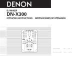
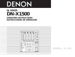
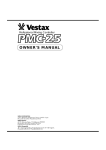
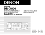
DJ MIXER
DN-X800
OPERATING INSTRUCTIONS
BEDIENUNGSANLEITUNG
MODE D’EMPLOI
INSTRUCCIONES DE OPERACION
MIC
1
2
3
PH1/LN1
PH2/LN3
PH3/LN5
4
GEBRUIKSAANWIJZING
BRUKSANVISNING
- 20
L
CUE
LINE7
R
PGM
- 20
0
10
MAIN MIC
ON/OFF
MIN
MAX
GAIN
DIGITAL1
MIN
LINE2
MAX
GAIN
DIGITAL2
LINE4
MIN
MAX
GAIN
DIGITAL3
MIN
LINE6
MAX
GAIN
DIGITAL4
LINE8
15
10
7
5
15
10
7
5
3
1
0
1
3
1
0
1
3
5
8 +
3
5
8 +
PWR
ZONE
MASTER
SUB WOOFER
MIC POST
CH FADER START
-26dB
+10dB
HI
ON/OFF
-26dB
+10dB
HI
CH FADER START
-26dB
10
+10dB
-26dB
+10dB
MID
-26dB
-26dB
+10dB
LOW
+10dB
MID
4
-26dB
10
+10dB
HI
-26dB
2
2
0
0
0
0
-26dB
+10dB
-26dB
LOW
+10dB
4
-26dB
BOOTH
4
2
+10dB
0
+10dB
0
LOW
LOW
0
10
AUX MIC
CH FADER START
10
LEVEL
MIC
SAMP.
H/S
BRAKE
H/S
BRAKE
CROSS
FADER
START B
CH 1
X
1
CH 2
3
4
H/S 2
A
B
H/S 2
1
CH 3
MONO
X
2
OFF
ON
CUE
SAMP.
ON/OFF
CROSSFADER
CONTOUR
MAIN
2
DIGITAL
CROSS
FADER
START A
MAX
FREQ.
EFFECT LOOP
6
+10dB
MID
4
2
LOW
MIN
8
6
+10dB
MID
10
LEVEL
METER
8
6
-26dB
4
10
0
10
8
6
-26dB
+10dB
MID
CH FADER START
+10dB
HI
8
6
-26dB
CH FADER START
-26dB
10
HI
8
2
RESET
CH 4
L-CUE
R-PGM
3
OFF
4
OFF
CUE
H/S 1
ASSIGN A
PGM
PAN
H/S 1
ASSIGN B
STEREO
CUE/PGM
0
10
LEVEL
PHONES
DJ MIXER
FOR ENGLISH READERS
FÜR DEUTSCHE LESER
POUR LES LECTEURS FRANCAIS
PARA LECTORES DE ESPAÑOL
VOOR NEDERLANDSTALIGE LEZERS
FOR SVENSKA LÄSARE
PAGE
SEITE
PAGE
PAGINA
PAGINA
SIDA
14
10
16
22
28
34
~
~
~
~
~
~
PAGE
SEITE
PAGE
PAGINA
PAGINA
SIDA
19
15
21
27
33
39
CAUTION
RISK OF ELECTRIC SHOCK
DO NOT OPEN
CAUTION: TO
REDUCE THE RISK OF ELECTRIC SHOCK, DO NOT REMOVE COVER (OR
BACK). NO USER SERVICEABLE PARTS INSIDE. REFER SERVICING TO
QUALIFIED SERVICE PESONNEL.
The lightning flash with arrowhead symbol, within an equilateral triangle, is intended to
alert the user to the presence of uninsulated “dangerous voltage” within the product’s
enclosure that may be of sufficient magnitude to constitute a risk of electric shock to
persons.
The exclamation point within an equilateral triangle is intended to alert the user to the
presence of important operating and maintenance (servicing) instructions in the literature
accompanying the appliance.
WARNING:
TO PREVENT FIRE OR SHOCK HAZARD, DO NOT EXPOSE THIS
APPLIANCE TO RAIN OR MOISTURE.
CAUTION:
1. Handle the power supply cord carefully
Do not damage or deform the power supply cord. If it
is damaged or deformed, it may cause electric shock
or malfunction when used. When removing from wall
outlet, be sure to remove by holding the plug
attachment and not by pulling the cord.
2. Do not open the top cover
In order to prevent electric shock, do not open the top
cover.
If problems occur, contact your DENON dealer.
3. Do not place anything inside
Do not place metal objects or spill liquid inside the DJ
mixer.
Electric shock or malfunction may result.
Please, record and retain the Model name and serial
number of your set shown on the rating label.
Model No. DN-X800
Serial No.
• DECLARATION OF CONFORMITY
We declare under our sole responsibility that this product,
to which this declaration relates, is in conformity with the
following standards:
EN60065, EN55013, EN55020, EN61000-3-2 and EN610003-3.
Following the provisions of 73/23/EEC, 89/336/EEC and
93/68/EEC Directive.
• DECLARACIÓN DE CONFORMIDAD
Declaramos bajo nuestra exclusiva responsabilidad que este
producto al que hace referencia esta declaración, está
conforme con los siguientes estándares:
EN60065, EN55013, EN55020, EN61000-3-2 y EN61000-33.
Siguiendo las provisiones de las Directivas 73/23/EEC,
89/336/EEC y 93/68/EEC.
• ÜBEREINSTIMMUNGSERKLÄRUNG
Wir erklären unter unserer Verantwortung, daß dieses
Produkt, auf das sich diese Erklärung bezieht, den
folgenden Standards entspricht:
EN60065, EN55013, EN55020, EN61000-3-2 und EN610003-3.
Entspricht den Verordnungen der Direktive 73/23/EEC,
89/336/EEC und 93/68/EEC.
• EENVORMIGHEIDSVERKLARING
Wij verklaren uitsluitend op onze verantwoordelijkheid dat
dit produkt, waarop deze verklaring betrekking heeft, in
overeenstemming is met de volgende normen:
EN60065, EN55013, EN55020, EN61000-3-2 en EN610003-3.
Volgens de bepalingen van de Richtlijnen 73/23/EEC,
89/336/EEC en 93/68/EEC.
• DECLARATION DE CONFORMITE
Nous déclarons sous notre seule responsabilité que
l’appareil, auquel se réfère cette déclaration, est conforme
aux standards suivants:
EN60065, EN55013, EN55020, EN61000-3-2 et EN610003-3.
D’après les dispositions de la Directive 73/23/EEC,
89/336/EEC et 93/68/EEC.
• ÖVERENSSTÄMMELSESINTYG
Härmed intygas helt på eget ansvar att denna produkt,
vilken detta intyg avser, uppfyller följande standarder:
EN60065, EN55013, EN55020, EN61000-3-2 och EN610003-3.
Enligt stadgarna i direktiv 73/23/EEC, 89/336/EEC och
93/68/EEC.
2
ENGLISH
DEUTSCH
FRANÇAIS
ESPAÑOL
NEDERLANDS
SVENSKA
NOTE ON USE / HINWEISE ZUM GEBRAUCH /
OBSERVATIONS RELATIVES A L’UTILISATION / NOTAS SOBRE EL USO /
ALVORENS TE GEBRUIKEN / OBSERVERA
FRONT PANEL DIAGRAM / VORDERES BEDIENFELD-SCHEMA /
SCHEMA DU PANNEAU AVANT / DIAGRAMA DEL PANEL FRONTAL /
OVERZICHT VAN VOORPANEEL / FRONTPANELEN
482
465
7
1
2
3
11
4
10
8
8
9
MIC
7
9
11
7
11
10
10
8
8
9
1
2
3
PH1/LN1
PH2/LN3
PH3/LN5
9
7
14
11
10
13
4
- 20
L
CUE
LINE7
R
PGM
- 20
0
ON/OFF
10
MAIN MIC
MIN
DIGITAL1
MIN
LINE2
MAX
GAIN
DIGITAL2
LINE4
CH FADER START
-26dB
ON/OFF
+10dB
HI
-26dB
+10dB
-26dB
+10dB
HI
-26dB
MAX
GAIN
DIGITAL3
-26dB
+10dB
CH FADER START
-26dB
10
MIN
LINE6
MAX
DIGITAL4
GAIN
-26dB
LINE8
17
16
18
32
15
10
7
5
3
1
0
1
3
5
8 +
15
10
7
5
3
1
0
1
3
5
8 +
PWR
ZONE
MASTER
CH FADER START
+10dB
10
-26dB
10
HI
+10dB
HI
SUB WOOFER
8
8
6
6
6
6
-26dB
+10dB
-26dB
MID
4
+10dB
MID
4
-26dB
2
2
2
0
0
0
0
-26dB
-26dB
+10dB
+10dB
-26dB
LOW
LOW
MIN
EFFECT LOOP
4
BOOTH
10
LEVEL
MIC
AUX MIC
CH FADER START
CROSS
FADER
START B
SAMP.
CH 1
H/S
BRAKE
CROSSFADER
CONTOUR
CH 2
MONO
X
2
3
4
H/S 2
A
H/S 2
B
1
2
CH 4
RESET
L-CUE
R-PGM
3
OFF
4
OFF
CUE
H/S 1
5
CH 3
H/S
BRAKE
X
1
OFF
ON
CUE
SAMP.
ON/OFF
10
MAIN
2
0
0
+10dB
LOW
DIGITAL
CROSS
FADER
START A
0
MAX
FREQ.
8
6
4
2
+10dB
10
LEVEL
METER
+10dB
MID
4
10
0
10
8
LOW
LOW
CH FADER START
-26dB
+10dB
HI
8
+10dB
MID
MID
31
28
6
PGM
PAN
H/S 1
26
30
27
30
0
STEREO
CUE/PGM
ASSIGN B
10
LEVEL
PHONES
26
29
24
29
23
22
DJ MIXER
21
25
20
7 x 10 hole
• Do not let insecticides, benzene, and thinner
come in contact with the set.
• Lassen Sie das Gerät nicht mit Insektiziden,
Benzin
oder
Verdünnungsmitteln
in
Berührung kommen.
• Ne pas mettre en contact des insecticides,
du benzène et un diluant avec l’appareil.
• No permita el contacto de insecticidas,
gasolina y diluyentes con el equipo.
• Laat geen insektenverdelgende middelen,
benzine of verfverdunner met dit apparaat in
kontakt komen.
• Se till att inte insektsmedel på spraybruk,
bensen och thinner kommer i kontakt med
apparatens hölje.
Loch 7 x 10
Trou 7 x 10
Orificio de 7 x 10
Opening 7 x 10
Hål, 7 x 10
REAR PANEL DIAGRAM / HINTERES ANSCHLUSSFELD-SCHEMA /
SCHEMA DU PANNEAU ARRIERE / DIAGRAMA DEL PANEL POSTERIOR /
OVERZICHT VAN ACHTERPANEEL / BAKPANELEN
38
37
POWER
34
ZONE
R
35
MAIN OUT
BALANCED
L
R
44
41
BOOTH
44
TAPE
OUT
46
CH4
UNBALANCED
LINE8
46
44
CH3
LINE7
LINE6
46
44
44
CH2
PHONO3/LINE5
LINE4
49
CH1
PHONO2/LINE3
LINE2
MAIN MIC
PHONO1/LINE1
L
L
ON
L
R
L
R
LN PH
L
R
LN PH
R
LN PH
OFF
1
X-EFFECTS
JACK
2
SEND
RETURN
DIGITAL4
DIGITAL OUT
SUB WOOFER
36
40
DIGITAL3
FADER
DIGITAL2
GND
DIGITAL1
AUX MIC
39
42
43
43
45
32
• Do not obstruct the ventilation holes.
• Die Belüftungsöffnungen dürfen nicht
verdeckt werden.
• Ne pas obstruer les trous d’aération.
• No obstruya los orificios de ventilación.
• De ventilatieopeningen mogen niet worden
beblokkeerd.
• Täpp inte till ventilationsöppningarna.
33
FADER
EFFECT
105
✽ (For sets with ventilation holes)
• Never disassemble or modify the set in any
way.
• Versuchen Sie niemals das Gerät
auseinander zu nehmen oder auf jegliche Art
zu verändern.
• Ne jamais démonter ou modifier l’appareil
d’une manière ou d’une autre.
• Nunca desarme o modifique el equipo de
ninguna manera.
• Nooit dit apparaat demonteren of op andere
wijze modifiëren.
• Ta inte isär apparaten och försök inte bygga
om den.
58
3
MIN
ASSIGN A
• Unplug the power cord when not using the
set for long periods of time.
• Wenn das Gerät eine längere Zeit nicht
verwendet werden soll, trennen Sie das
Netzkabel vom Netzstecker.
• Débrancher le cordon d’alimentation lorsque
l’appareil n’est pas utilisé pendant de
longues périodes.
• Desconecte el cordón de energía cuando no
utilice el equipo por mucho tiempo.
• Neem altijd het netsnoer uit het stopkontakt
wanneer het apparaat gedurende een lange
periode niet wordt gebruikt.
• Koppla ur nätkabeln om apparaten inte
kommer att användas i lång tid.
• Handle the power cord carefully.
Hold the plug when unplugging the cord.
• Gehen Sie vorsichtig mit dem Netzkabel um.
Halten Sie das Kabel am Stecker, wenn Sie
den Stecker herausziehen.
• Manipuler le cordon d’alimentation avec
précaution.
Tenir la prise lors du débranchement du
cordon.
• Maneje el cordón de energía con cuidado.
Sostenga el enchufe cuando desconecte el
cordón de energía.
• Hanteer het netsnoer voorzichtig.
Houd het snoer bij de stekker vast wanneer
deze moet worden aan- of losgekoppeld.
• Hantera nätkabeln varsamt.
Håll i kabeln när den kopplas från el-uttaget.
MAX
GAIN
15
MIC POST
177
101.6
• Avoid high temperatures.
Allow for sufficient heat dispersion when
installed on a rack.
• Vermeiden Sie hohe Temperaturen.
Beachten Sie, daß eine ausreichend
Luftzirkulation gewährleistet wird, wenn das
Gerät auf ein Regal gestellt wird.
• Eviter des températures élevées
Tenir compte d’une dispersion de chaleur
suffisante lors de l’installation sur une
étagère.
• Evite altas temperaturas
Permite la suficiente dispersión del calor
cuando está instalado en la consola.
• Vermijd hoge temperaturen.
Zorg voor een degelijk hitteafvoer indien het
apparaat op een rek wordt geplaatst.
• Undvik höga temperaturer.
Se till att det finns möjlighet till god
värmeavledning vid montering i ett rack.
• Keep the set free from moisture, water, and
dust.
• Halten Sie das Gerät von Feuchtigkeit,
Wasser und Staub fern.
• Protéger l’appareil contre l’humidité, l’eau et
lapoussière.
• Mantenga el equipo libre de humedad, agua
y polvo.
• Laat geen vochtigheid, water of stof in het
apparaat binnendringen.
• Utsätt inte apparaten för fukt, vatten och
damm.
• Do not let foreign objects in the set.
• Keine fremden Gegenstände in das Gerät
kommen lassen.
• Ne pas laisser des objets étrangers dans
l’appareil.
• No deje objetos extraños dentro del equipo.
• Laat geen vreemde voorwerpen in dit
apparaat vallen.
• Se till att främmande föremål inte tränger in i
apparaten.
19
12
47
45
48
43
Unit:
Gerät:
Unité:
Unidad:
Toestel:
Enhet:
43
47
mm
mm
mm
mm
mm
mm
47
50
ENGLISH
– TABLE OF CONTENTS –
z
x
c
v
Main features ..................................................................4
Installation .......................................................................4
Part names and functions ...........................................4, 5
Connections.....................................................................6
b
n
m
,
3 PART NAMES AND FUNCTIONS
Fader start .......................................................................7
X-effect ............................................................................8
Replacing the crossfader.................................................9
Specifications ..................................................................9
(1) Front Panel
q
Please check to make sure the following items are included with the main unit in the carton:
w Connection cords (3.5 mm stereo mini cord) ..................2
1 MAIN FEATURES
CONGRATULATIONS! You have purchased the DENON
DN-X800 DJ mixer from DENON.
1. X-Effect
The X-Effect is a unique feature which is designed to work
with the DENON DN-2100F and DN-2600F CD players.
The fader start of the below functions can be used with the
Crossfader.
Sampler, Hot start brake/platter, Hot start 1, 2 (each drive).
2. CH. Fader and Crossfader start
The CD player can be started or stopped simply by
increasing or decreasing the level of the CH fader or by
using the cross fader left to right or right to left. (This
function can only be used when the DENON CD players
DN-1800F, DN-2100F or DN-2600F is connected to the
DN-X800.)
3. Digital outputs
The DN-X800 allows you to record directly to CD-R,
MiniDisc or a hard disk device through it’s exclusive coaxial
digital outputs.
The digital outputs maintains a constant 16 bit / 44.1 kHz
signal.
5. Enhanced input/output terminals (Analog)
8 Line, 3 Phono, 2 microphone systems, 2 Main outputs,
Zone output, Booth output, Sub woofer output and tape
output are provided independently. Effect in/out terminals
are also provided for a external effects processor.
6. 3-Band equalizer/Gain
Bass, Mid, Treble and Gain controls are available on every
input channel.
7. Crossfader contour
This feature allows adjusting the “shape” of the Crossfader
response from a gentle curve for smooth, long running
fades, to the steep pitch required for top performance cut
and scratch effects.
8. Mic post
This feature will pass the Main Mic signal into the Zone,
Booth, Tape output and Digital output signal path.
In the OFF mode, the MIC signal will not be routed through
the above outputs.
w
e
r
t
• Puts the Main Mic signal into the Main outputs signal
path.
• When the button is pressed, the Main Mic is on and
the adjacent orange indicator lights.
!3
i
Min. 3 cm
2
3
PH1/LN1
PH2/LN3
PH3/LN5
4
- 20
L
CUE
LINE7
R
PGM
- 20
0
10
MAIN MIC
ON/OFF
MIN
MAX
GAIN
DIGITAL1
MIN
LINE2
MAX
GAIN
DIGITAL2
LINE4
MIN
MAX
GAIN
DIGITAL3
MIN
LINE6
MAX
GAIN
DIGITAL4
LINE8
15
10
7
5
3
1
0
1
3
5
8 +
15
10
7
5
3
1
0
1
3
5
8 +
CH FADER START
+10dB
HI
ON/OFF
-26dB
+10dB
HI
CH FADER START
-26dB
10
+10dB
+10dB
MID
4
ZONE
MASTER
o
SUB WOOFER
+10dB
MIN
EFFECT LOOP
6
10
AUX MIC
CH FADER START
2
0
0
+10dB
-26dB
LOW
0
+10dB
LOW
10
LEVEL
MIC
CUE
SAMP.
CROSS
FADER
START B
SAMP.
ON/OFF
CH 1
2
3
4
H/S 2
CH 3
MONO
X
X
1
CH 2
H/S
BRAKE
H/S
BRAKE
CROSSFADER
CONTOUR
OFF
ON
MAIN
2
A
B
H/S 2
1
2
CH 4
Source input select switch
• Selects either a Phono/Line or Line input for the
source.
4
DIGITAL
CROSS
FADER
START A
0
MAX
FREQ.
8
BOOTH
4
0
-26dB
10
LEVEL
METER
6
+10dB
MID
2
LOW
10
0
10
8
-26dB
4
0
-26dB
+10dB
LOW
+10dB
HI
6
+10dB
MID
2
0
-26dB
+10dB
LOW
CH FADER START
-26dB
10
8
-26dB
4
2
-26dB
CH FADER START
+10dB
6
-26dB
+10dB
MID
HI
8
6
-26dB
+10dB
MID
-26dB
10
HI
8
-26dB
BOOTH LEVEL control
• Adjusts the level of the Booth outputs.
!5
MASTER LEVEL fader
• Adjusts the level of the Main outputs. Signals from the
channels selected with the Assign switches will be
output using the Source input fader (Ch. fader) and the
Crossfader, while signals from other channels will be
outputs using the Source input fader (Ch. fader).
!6
Source EQ controls
• Adjusts the level of the selected input 0 to +10 dB.
PWR
MIC POST
-26dB
!4
AUX MIC ON/OFF button
GAIN level control
ZONE METER button
• When this button is pressed down and held, the meter
indicates the stereo level in the LEFT and RIGHT
meter output. The adjacent green indicator lights.
AUX MIC level control
NOTE:
Clipping may occur if adjustments are set to harsh.
ZONE level control
• Adjusts the level of the Zone outputs.
MIC POST ON/OFF button
• Puts the Aux Mic signal into the mixer signal path.
• When the button is pressed, the Aux Mic is on and the
adjacent orange indicator lights.
Source input fader (Ch. fader)
• Controls the level of the selected Input.
!2
• Contour the frequency response of the selected
inputs.
HI
• Adjusts the high-tone sound -26 dB to +10 dB.
At the center position, sound is flat.
MID
• Adjusts the mid-tone sound -26 dB to +10 dB.
At the center position, sound is flat.
LOW
• Adjusts the low-tone sound -26 dB to +10 dB.
At the center position, sound is flat.
1
!1
• Adjusts the level of the Aux Mic input.
y
u
MIC
NOTE:
You must first set the pitch slider to zero % of the
digital output source (CD, MD) before it's power is
turned on. If the green digital indicator is flashing on
the mixer, please perform the above steps.
MAIN MIC ON/OFF button
• Puts the Main Mic signal into the Zone, Booth Tape
and Digital out signal path.
• When the button is pressed, the adjacent green
indicator lights.
2 INSTALLATION
!7
Peak dB CUE/PROGRAM meter
• Displays the output level following Master Level
adjustment, the peak level is held for 1 second.
Display range : -20 dB to +8 dB.
• Can switch between two display mode. See below
@3.
SUBWOOFER frequency control
• Adjusts the cut off frequency of the low pass filter 40
Hz to 200 Hz.
• The low adjustment, will effect the Subwoofer output.
!8
EFFECT LOOP MAIN button
• Routes the Main signal through the external processor
attached to the EFFECT connectors on the rear.
• When the button is pressed in, the adjacent orange
indicator lights. (When the processor isn't
attached,indicator blinks.)
!9
EFFECT LOOP MIC button
• Routes the Main Mic signal through the external
processor attached to the EFFECT connectors on the
rear.
• When the button is pressed in, the adjacent orange
indicator lights. (When the processor isn't
attached,indicator blinks.)
RESET
L-CUE
R-PGM
3
OFF
4
OFF
CUE
H/S 1
ASSIGN A
4
MAIN MIC level control
LINE/DIGITAL input select switch
• Selects either a Line (analog) or Digital Input for the
Source.
• The adjacent green indicator flashes when the digital
signal is unlocked and remains lit when the digital
signal is locked.
• Adjusts the level of the Main Mic input.
4. Digital inputs
The DN-X800 accepts up to 4 digital inputs.
Such as our family of performers, DN-1800F, DN-2100F,
DN-2600F, DP-DJ151 or any device with a digital output.
The sampling frequency range can be 32 kHz, 44.1 kHz or
48 kHz.
When the DN-X800 is mounted inside a coffin or DJ booth, we
recommend leaving a 3 cm blank space above the mixer if
possible.
!0
• Contour the frequency response of the Main Mic input
-12 dB to +12 dB.
HI
• Adjusts high-tone microphone sound -12 dB to
+12 dB.
At the center position, sound is flat.
MID
• Adjusts mid-tone microphone sound -12 dB to +12 dB.
At the center position, sound is flat.
LOW
• Adjusts low-tone microphone sound -12 dB to +12 dB.
At the center position, sound is flat.
• ACCESSORIES
q Operating instructions ....................................................1
MIC EQ controls
PGM
PAN
H/S 1
ASSIGN B
STEREO
CUE/PGM
0
10
LEVEL
PHONES
DJ MIXER
NOTE:
When the Effect Loop Main and Mic are on, the
signal of Mic is output to all the outputs regardless
of setting the Main Mic and the Post Mic.
ENGLISH
@0
RESET switch
#0
• Returns to initial settings when this switch is pressed.
@1
• The Fader Start is executed by connecting the
Expansion Jack of the RC of the DN-2100F and the
DN-2600F, the item that is executed by Crossfader
and Ch. fader are selected by the button in each Ch..
It is not possible to use when the RC is not connected.
SAMP. buttons
This function will start the Sampler of the DN-2600F
by using Crossfader and Ch. fader are turned on/off.
H/S BRAKE buttons
This button provides 2 functions, Brake and Platter-S.
You first need to load a Hot Start(s) to activate this
feature.
By pressing either H/S Brake button once, will activate
H/S Brake mode (orange indicator is lit) .
By pressing the same button once more, this will
activate H/S Platter-S mode (indicator is flashing).
A third press will turn this function OFF.
See “X-EFFECT” to use this feature on page 8.
H/S 1, 2 buttons
This function will start the Hot Start of the DN-2100F
and the DN-2600F by using Crossfader and Ch. fader
are turned on/off.
HEADPHONE output jack
• Accepts 1/4” stereo headphone plugs.
@2
HEADPHONE level control
• Adjusts the volume for the headphones.
@3
HEADPHONE mode button
• In the STEREO mode, this button feeds STEREO
Program and Cue to both earcups, in the MONO
mode, the Headphone circuit provides MONO Cue to
the left ear and MONO Program to the right.
• In the STEREO mode, the meter indicates the stereo
level in the LEFT and RIGHT Main Outputs. In the
MONO mode, mono CUE level is displayed on the
Left meter and mono PROGRAM level is displayed on
the Right meter.
• In the MONO mode, the adjacent green indicator
lights.
@4
HEADPHONE PAN control
• Serves two purposes…In the STEREO mode it
changes the relative levels of the Cue and Program
mixed together in both earcups. In the MONO mode it
changes the balance between the Mono Cue in the
left ear cup and the Mono Program in the right.
@5
CUE buttons
• Pressing in any or all of the CUE buttons routes the
respective Source to the Headphone and Meter Cue
sections. Pressing multiple buttons makes it possible
to derive mixed sound from the selected sources. The
adjacent red indicator illuminates when the button is
depressed.
@6
POWER indicator
CROSSFADER START A, B buttons
• The function to start the performance of CD Player
with Crossfader automatically is turned on/off.
• When the button is pressed in, the Crossfader Start is
on and the adjacent orange indicator lights.
$2
#5
MAIN OUT (UNBALANCED) jacks
• This stereo pair of RCA jacks provide a unbalanced line
level output.
• Connect these jacks to the unbalanced analog input
jacks on an amplifier or console.
#6
#7
#8
DIGITAL 1, 2, 3, 4 input jacks
• These RCA jacks are Inputs for any digital output
device.
• We recommend using a 75Ω/ohm RCA cord for best
digital transfer. (available from any audio/video retailer)
$4
LINE 2, 4, 6, 7, 8 input jacks
• These stereo pairs of unbalanced RCA jacks are Inputs
for any line level device.
$5
Ch 3, 4 FADER output jacks
• Connect these jacks to the Fader input jacks of the
DN-1800F, the DN-2100F and the DN-2600F using the
3.5 mm stereo mini cord.
• These RCA jacks provide a digital output data. The
signal is unaffected by the Master Level fader. Output
is controlled by Ch. fader volume.
• We recommend using a 75Ω/ohm RCA cord for best
digital transfer. (available from any audio/video retailer)
$6
ZONE OUT (BALANCED) connectors
$7
PHONO 1, 2, 3 / LINE 1, 3, 5 input jacks
• These stereo pairs of unbalanced RCA jacks are Inputs
for a Phono (RIAA) stage for magnetic (MM) cartridges
or a Line stage suitable for any device, such as a CD
player.
PHONO 1, 2, 3 / LINE 1, 3, 5 switches
• These switches change the Input from Phono to a
Line level inputs.
• These switches set a Line level inputs when Turntable
is not connected.
$8
Phono Ground screw
• This screws provide a place to connect the ground
wire from a turntable.
This terminal is exclusively for a turntable grounding
and not a safety earth ground.
$9
MAIN MIC input connector
• Neutrik combo jack.
• Accepts either a balanced microphone with an XLR
connector or an unbalanced microphone with 1/4”
mono jacks.
BOOTH OUT jacks
• This stereo pair of RCA jacks provide a unbalanced line
level output with independent front panel Booth Level
controls and are not affected by the Master Level
control.
• Connect these jacks to the unbalanced analog input
jacks on an amplifier or console.
#9
$3
DIGITAL OUT 1, 2 jacks
• These XLR type connectors provide a balanced line
level output with independent front panel Zone Level
controls and are not affected by the Master Level
control.
• Connect these connectors to the balanced analog
input connectors on an amplifier or console.
• Pin layout 1. Common 2. Hot 3. Cold
• Applicable connector: Cannon XLR-3-31 or equivalent.
NOTE:
Do not short-circuit the hot or cold pin with the common
pin.
• When the red indicator is lit, the DN-X800 is ready to
go.
EFFECT jacks
• These 1/4” stereo jacks allow stereo external
processing of the Program signal.
• These are switching jacks --- always complete the loop
when connecting a send and return, or no sound will
be heard.
MAIN OUT (BALANCED) connectors
• These XLR type connectors provide a balanced line
level output.
• Connect these connectors to the balanced analog
input connectors on an amplifier or console.
• Pin layout 1. Common 2. Hot 3. Cold
• Applicable connector: Cannon XLR-3-31 or equivalent.
NOTE:
Do not short-circuit the hot or cold pin with the common
pin.
%0
AUX MIC input jack
• Accepts an unbalanced microphone with 1/4” mono
jacks.
X-EFFECTS JACK
• Connect this jack to the remote of the DN-2100F and
the DN-2600F using the 3.5 mm stereo mini cord.
$0
SUBWOOFER output jack
• This 1/4” mono jacks provide a mono line level output
of Main Out. The signal is affected by the Master
Level fader.
• Connect this jacks to the subwoofer input jack on an
amplifier.
CROSSFADER CONTOUR control
• Allows adjusting the “shape” of the Crossfader
response from a gentle curve for smooth, long running
fades, to the steep pitch required for top performance
cut and scratch effects.
@9
#2
#4
CH. FADER START switches
• This function will start the performance of CD Player
with Ch. fader automatically is turned on/off.
POWER switch
• Press the switch to turn the power on.
CROSSFADER
• Controls the relative output level from the summed A
and B Mixes. When the fader is at its far left, only the
A Mix is heard from the Outputs. As the fader is
moved toward the right, the amount of B Mix is
increased and the amount of A Mix is decreased.
When the fader is centered, equal amounts of A and B
Mixes are routed to the Outputs. Fully right is all B Mix
at the Outputs.
@8
#1
#3
CROSSFADE ASSIGN A, B switches
• Assigns the Crossfader to any of the four Input
Channels and Off.
OFF
Select when not using the crossfader.
1 to 4
Select what channels (CH-1 to CH-4) to assign to A
and B.
Channels not assigned to A or B are output without
passing through the crossfader.
@7
(2) Rear Panel
X-EFFECT function buttons
$1
TAPE OUT jacks
• This stereo pair of RCA jacks provide a line level
output. The signal is unaffected by the Master Level
fader. Output is controlled by Ch. fader volume.
• It is intended for use with a tape recorder, but is not
restricted to that purpose. Output is controlled by Ch.
fader volume.
5
ENGLISH
NOTE:
Always switch on your audio input sources such as CD players
first, then your mixer, and finally any amplifiers. When turning
off, always reverse this operation by turning off amplifiers,
then your mixer, and then input units.
4 CONNECTIONS
4. Connect all stereo input sources. Then connect any effects
into the stereo Effect, if used. Connect your Microphone(s)
and monitor headphones. Make sure all faders are at
“zero” and the unit is off. Take care to connect only one
cable at a time. pay attention to L and R position of jacks,
on both the DN-X800 and outboard gear.
5. Connect the stereo outputs to the power amplifier(s) and/or
tape deck(s) and/or MD recorder(s) and/or CD recorder(s).
Plug the DN-X800 into AC power outlet.
Balanced or unbalanced
Microphones
Turntable 2
Turntable 1
ANTI-S
2
1
1
ANTI-S
4
3 210
3 210
1
4
0
0
PITCH
KEY ADJUST
-12
0
PITCH
KEY ADJUST
-12
SLOW
BRAKE
Quartz
0
Quartz
0
ON
OFF
POWER
POWER
+12
START
/STOP
78
33
DP-DJ151 Digital
45
0
ON
OFF
POWER
+12
START
/STOP
PITCH
-12
SLOW
BRAKE
Quartz
ON
OFF
765
2
TING
KA
765
765
ANTI-S
3
3
3
4
TING
KA
3 210
TING
KA
KEY ADJUST
SLOW
BRAKE
2
Turntable 3
Booth unbalanced power amplifier
4
Main unbalanced power amplifier
Tape deck
4
1. Make certain AC power is off while making connections.
2. Quality cables make a big difference in fidelity and punch.
Use high-quality, audio cables.
3. Do not use excessively long cables. Be sure plugs and jacks
are securely fastened. Loose connections cause hum,
noise, or intermittents that could damage your speakers.
4
Refer to the Connection Diagram below.
+12
START
/STOP
78
33
78
DP-DJ151 Digital
45
33
DP-DJ151 Digital
45
Main balanced power amplifier
R
POWER
ZONE
MAIN OUT
BALANCED
R
L
L
R
L
R
BOOTH
L
R
L
TAPE
OUT
CH4
UNBALANCED
LINE8
R
L
CH3
LINE7
LINE6
R
L
CH1
CH2
PHONO3/LINE5
LINE4
R
PHONO2/LINE3
LINE2
MAIN MIC
PHONO1/LINE1
L
ON
L
L
R
R
L
LN PH
L
R
LN PH
R
LN PH
OFF
1
X-EFFECTS
JACK
2
SEND
RETURN
Unbalanced Microphones
DIGITAL OUT
DIGITAL4
SUB WOOFER
FADER
DIGITAL3
FADER
DIGITAL2
GND
DIGITAL1
EFFECT
AUX MIC
Zone balanced power amplifier
L
R
R
L
R
R
L
L
MD recorder
CD recorder or PC
TRACK
OPEN/
CLOSE
M
T. REMAIN ELAPSED
S
SINGLE
F
M
T. REMAIN ELAPSED
S
SINGLE
F
PITCH
CONTINUE
2
PITCH
SCAN
TRACK
OPEN/
CLOSE
PITCH
CONTINUE
1
SEARCH
SEARCH
PITCH BEND
PITCH
SCAN
PITCH BEND
PITCH%
PITCH%
0%
JOG
MODE
CONT./
SINGLE
TRACK
TIME
CUE
0%
JOG
MODE
PLAY/PAUSE
CONT./
SINGLE
TRACK
CUE
TIME
CUE
PLAY/PAUSE
CUE
REMOTE CONTROL UNIT RC-47
1
OPEN/CLOSE
OPEN/CLOSE
1
2
2
POWER
ON
OFF
OPEN/
CLOSE
OPEN/
CLOSE
1
CONT./SINGLE
TIME
NEXT TR.
START
MEMO
BRAKE
PITCH
2
KEY
CONT./SINGLE
TIME
NEXT TR.
START
MEMO
BEN
D
PITCH BEND
EXIT/
RELOOP
RVB
LOOP
TAP
KEY
STOP
CUE
LOOP
END MON.
SEARCH
PUSH ENTER
SEARCH
FLG
SCAN
EFFECT
PITCH
ON/OFF
DATA MASTER
DIGI-S
PROGRAM
B
2
FIL
REVERSE
BEN
D
1
0%
KEY
SCAN
PLAY/WRITE
PLAY/PAUSE
MODE
CUE
6
PITCH
KEY
OPEN/CLOSE
1
2
POWER
OFF
CD player
PITCH BEND
B
EXIT/
RELOOP
2
FIL
RVB
REVERSE
LOOP
TAP
PUSH ENTER
FLG
PITCH
ON/OFF
DATA MASTER
STOP
PLAY/WRITE
PLAY/PAUSE
CUE
MODE
PRESET
REMOTE CONTROL UNIT RC-46
OPEN/CLOSE
ON
Effects processor
A
1
CUE
PRESET
1
Subwoofer with
Built-in amplifier
BRAKE
END MON.
PROGRAM
SEARCH
A
LOOP
END MON.
SEARCH
EFFECT
DIGI-S
CD player
2
0%
ENGLISH
5 FADER START
Channel Fader Start
If the separately sold DN-1800F, DN-2100F and DN-2600F players are connected to CH-3 or CH-4, they can be started using the
source input fader (Ch. fader) or Crossfader, as long as the 3.5 mm stereo mini cords have been connected.
Crossfader Start
Turn on the Ch. fader start switch.
CH FADER START
1
ON
CH3
Fader jack
CH4
Fader jack
Move the source input fader (Ch.
fader) of CH-3 or Ch-4 control all
the way to the bottom.
DN-X800
1
Using the Crossfader Assign A B switches, select
the channel (CH-3 or CH-4) that the CD player is
connected.
2
Press the Crossfader Start A, B buttons of the
channel connected to the CD player to be controlled.
OFF
CH FADER START
Slide the Crossfader all the way in direction opposite
the source you want to start. ( In the following
example, startup is done with the CD player
connected to CH-3 set to Assign A. )
10
8
MIC
1
2
PH1/LN1
3
PH2/LN3
4
PH3/LN5
- 20
L
CUE
LINE7
R
PGM
- 20
0
ON/OFF
10
MAIN MIC
MIN
MAX
DIGITAL1
GAIN
MIN
LINE2
MAX
GAIN
DIGITAL2
MIN
LINE4
MAX
GAIN
DIGITAL3
MIN
LINE6
MAX
GAIN
DIGITAL4
LINE8
15
10
7
5
15
10
7
5
3
1
0
1
3
1
0
1
3
5
8 +
3
5
8 +
2
PWR
ZONE
MASTER
SUB WOOFER
6
MIC POST
CH FADER START
-26dB
+10dB
HI
ON/OFF
-26dB
CH FADER START
-26dB
+10dB
10
HI
+10dB
-26dB
MID
3.5 mm stereo
mini cord
MID
+10dB
-26dB
LOW
-26dB
+10dB
-26dB
BOOTH
-26dB
+10dB
0
10
LEVEL
LOW
MIC
CH FADER START
SAMP.
H/S
BRAKE
CROSS
FADER
START B
CH 1
CROSSFADER
CONTOUR
X
1
CH 2
3
H/S 2
4
A
B
H/S 2
1
2
0
X
1
L-CUE
R-PGM
3
OFF
4
CUE
H/S 1
TRACK
OPEN/
CLOSE
M
T. REMAIN ELAPSED
PGM
PAN
H/S 1
ASSIGN B
S
SINGLE
F
1
M
T. REMAIN ELAPSED
SEARCH
PITCH BEND
0
S
SINGLE
F
SCAN
TRACK
TIME
CUE
PITCH BEND
When you want to start the
player, move up the source input
fader (Ch. fader) and the CD
player will begin playing.
0%
JOG
MODE
PLAY/PAUSE
CONT./
SINGLE
TRACK
CUE
TIME
CUE
PLAY/PAUSE
CUE
REMOTE CONTROL UNIT RC-47
1
CD1
Fader jack
OPEN/CLOSE
OPEN/CLOSE
1
2
2
CD2
Fader jack
POWER
4
CH FADER START
4
A
B
4
DN-1800F
Set the cue point on the left drive.
DN-2100F and DN-2600F
Set the A-1 or A-2 point on the left drive.
5
Use the Crossfader Contour control to control the
cross fader startup curve.
10
8
6
4
ON
3
ASSIGN A
PITCH%
0%
CONT./
SINGLE
3
DJ MIXER
PITCH
CONTINUE
DN-1800F
Set the cue point on either drive.
DN-2100F and DN-2600F
Set the A-1 or A-2 point on either drive.
PITCH
PITCH%
JOG
MODE
10
LEVEL
PHONES
2
PITCH
SCAN
TRACK
OPEN/
CLOSE
PITCH
CONTINUE
STEREO
CUE/PGM
2
OFF
RESET
CH 4
OFF
ASSIGN A
SEARCH
CH 3
MONO
X
2
OFF
ON
CUE
SAMP.
H/S
BRAKE
ON/OFF
10
3.5 mm stereo
mini cord
0
DIGITAL
CROSS
FADER
START A
0
AUX MIC
MAIN
2
0
+10dB
LOW
3
2
4
2
0
+10dB
MAX
FREQ.
EFFECT LOOP
6
4
2
LOW
LOW
MIN
8
+10dB
MID
4
0
0
-26dB
10
LEVEL
METER
6
-26dB
MID
0
8
+10dB
2
4
10
10
6
-26dB
4
2
+10dB
HI
8
+10dB
MID
4
-26dB
10
6
-26dB
+10dB
CH FADER START
+10dB
HI
8
6
+10dB
-26dB
10
HI
8
-26dB
CH FADER START
When the Crossfader is slid in the opposite direction
as in “3”, CD player play will begin.
OFF
2
DN-1800F
0
6
NOTE:
Use the analog inputs/outputs when the DN-1800F, the DN-2100F and the DN-2600F are moved by FADER START.
NOTES:
• Channels selected with the Crossfader Assign A, B
switches and the Crossfader Start A, B buttons cannot
be started with the source input fader (Ch. fader).
• Ch. Fader Start and Cross Fader Start for the same
source will not operate simultaneously. You must select
from either one. If both Ch. Fader and Cross Fader
switches are ON, priority will be the cross fader.
X
1
2
3
OFF
4
A
B
ASSIGN A
7
ENGLISH
The indicator of H/S 1, 2 and SAMP. change automatically if Assign switches are changed to CH-1 or CH-2.
6 X-EFFECT
If the separately sold DN-2100F and DN-2600F players are connected below, they can be started using the source input fader (Ch.
fader) or Crossfader.
The below function can be started using the source input fader (Ch. fader) or Crossfader by setting it with CD PLAYER.
CROSS
FADER
START A
1
CH2
Input jack
H/S
BRAKE
Lit
X
2
3
OFF
CH1
Input jack
SAMP.
H/S
BRAKE
Sampler (DN-2600F), Hot Start Brake Platter (DN-2100F and DN-2600F), Hot Start (DN-2100F and DN-2600F)
4
X-EFFECTS jack
H/S 2
X
A
B
H/S 1
2
PH1/LN1
3
PH2/LN3
4
PH3/LN5
- 20
L
CUE
LINE7
R
PGM
- 20
MIN
MAX
DIGITAL1
GAIN
MIN
LINE2
MAX
DIGITAL2
GAIN
MIN
LINE4
MAX
GAIN
DIGITAL3
MIN
LINE6
MAX
GAIN
DIGITAL4
LINE8
15
10
7
5
15
10
7
5
3
1
0
1
3
1
0
1
3
5
8 +
3
5
8 +
PWR
ZONE
MASTER
SUB WOOFER
MIC POST
CH FADER START
-26dB
ON/OFF
+10dB
HI
-26dB
CH FADER START
-26dB
+10dB
10
HI
-26dB
-26dB
+10dB
-26dB
RCA cord
LOW
+10dB
HI
-26dB
2
2
0
0
0
-26dB
+10dB
-26dB
LOW
+10dB
-26dB
EFFECT LOOP
6
4
0
10
LEVEL
MIC
DIGITAL
CROSS
FADER
START A
0
AUX MIC
SAMP.
CROSS
FADER
START B
SAMP.
CH 1
H/S
BRAKE
CROSSFADER
CONTOUR
CH FADER START
CH 2
MONO
X
2
3
OFF
H/S 2
4
CH 3
H/S
BRAKE
X
1
ON
CUE
ON/OFF
10
MAIN
2
0
+10dB
LOW
LOW
FREQ.
8
BOOTH
4
2
0
+10dB
LEVEL
MAX
+10dB
MID
4
2
LOW
MIN
6
+10dB
MID
10
METER
8
6
-26dB
4
10
0
10
8
+10dB
MID
4
-26dB
10
HI
6
-26dB
+10dB
MID
CH FADER START
+10dB
8
6
+10dB
MID
-26dB
10
HI
8
-26dB
CH FADER START
+10dB
A
H/S 2
B
1
2
RESET
CH 4
L-CUE
R-PGM
3
OFF
4
OFF
CUE
H/S 1
PGM
STEREO
CUE/PGM
PAN
H/S 1
ASSIGN B
ASSIGN A
OPEN/
CLOSE
0
10
LEVEL
PHONES
2
3
4
ASSIGN B
Lit
DJ MIXER
CROSS
FADER
START A
SAMP.
H/S
BRAKE
1
2
3
OFF
CROSS
FADER
START B
Lit
SAMP.
Lit
X
RCA cord
1
ON/OFF
10
1
OFF
ASSIGN A
3.5 mm stereo mini cord
MIC
0
H/S 2
H/S 1
DN-X800
MAIN MIC
CROSS
FADER
START B
Lit
SAMP.
4
H/S 2
A
B
H/S 1
H/S
BRAKE
X
H/S 2
1
2
3
OFF
4
H/S 1
ASSIGN A
ASSIGN B
Lit
OPEN/
CLOSE
TOTAL REMAIN ELAPSED
CONT. SINGLE REPEAT
NEXT TR
PITCH %
MEMO
BRAKE
PITCH
m
s
EOM
SEARCH
SCAN
1
ND
EXIT/
RELOOP
2
FIL
RVB
REVERSE
LOOP
BE
TAP
KEY
DIGI-S
CUE
START
NEXT TR
s
PITCH %
MEMO
EOM
LOOP
SEARCH
PUSH ENTER
SEARCH
FLG
SCAN
EFFECT
PITCH
0%
PLAY/WRITE
MODE
BRAKE
PITCH
KEY
f
SAMP RVS
DIGI-S
EFFECT
END MON.
PROGRAM
ON/OFF
PLAY/PAUSE
m
A1 B
EXIT
A2 B
END MON.
A
1
PITCH BEND
(2) Starting with Fader Start
B
EXIT/
RELOOP
2
FIL
RVB
REVERSE
LOOP
TAP
PUSH ENTER
FLG
PITCH
ON/OFF
DATA MASTER
STOP
0%
PLAY/WRITE
CUE
CUE
PLAY/PAUSE
RC Expansion jack
Channel Fader Start
MODE
Crossfader Start
CUE
PRESET
PRESET
REMOTE CONTROL UNIT RC-46
OPEN/CLOSE
1
TOTAL REMAIN ELAPSED
GO
LOOP
LOOP
D.OUT FULL LOCK
DATA MASTER
STOP
TIME
NEXT TR.
PITCH BEND
B
ND
SEARCH
CONT./SINGLE
SAMP RVS
DIGI-S
EFFECT
PROGRAM
A
EFFECT
MEMO PROG.
BRAKE PLAT-S PLAT-H
f
A1 B
EXIT
A2 B
LOOP
CONT. SINGLE REPEAT
2
KEY
GO
LOOP
LOOP
D.OUT FULL LOCK
END MON.
DIGI-S
START
BE
MEMO PROG.
BRAKE PLAT-S PLAT-H
TIME
NEXT TR.
KEY
1
CONT./SINGLE
Turn on the Ch. fader start switch.
OPEN/CLOSE
1
CD1
Output jack
2
2
CD2
Output jack
POWER
CH FADER START
1
ON
ON
Move the source input fader (Ch.
fader) of CH-1 or CH-2 control all
the way to the bottom.
NOTE:
Use the analog inputs/outputs when the DN-2600F and the DN-2100F are moved by X-EFFECT.
Using the Crossfader Assign A B switches, select
the channel (CH-1 or CH-2) that the CD player is
connected.
2
Press the Crossfader Start A, B buttons of the
channel connected to the CD player to be controlled.
OFF
DN-2600F
OFF
1
CH FADER START
Slide the Crossfader all the way in direction opposite
the source you want to start. ( In the following
example, startup is done with the CD player
connected to CH-1 set to Assign A. )
10
8
2
(1) Selecting the mode
6
4
Sampler (DN-2600F)
Hot Start (DN-2100F and DN-2600F)
3
2
0
X
1
The sound for the Sampler is recorded with the
DN-2600F.
• When the sound is recorded, the adjacent green
indicator lights.
1
1
Press the H/S 1, 2 button.
Press the SAMP. button.
2
SAMP.
Flashing
2
3
OFF
Set the Hot Start 1 and/or 2 point of the CD player.
• When set the Hot Start point, the adjacent orange
indicator lights.
2
When you want to start the
player, move up the source input
fader (Ch. fader) and the CD
player will begin playing.
3
CH FADER START
Flashing
A
B
10
8
6
4
4
H/S 1
4
ASSIGN A
Use the Crossfader Contour control to control the
cross fader startup curve.
When the Crossfader is slid in the opposite direction
as in “3”, CD player will begin.
2
0
5
Hot Start Brake Platter (DN-2100F and DN-2600F)
Press the H/S BRAKE button, and the adjacent
orange indicator lights.
1
H/S
BRAKE
Lit
8
The function for the Brake stop is done by using
Crossfader and source input fader. (Ch. fader) Ch Fader
must be set and left in the up position.
NOTES:
• Channels selected with the Crossfader Assign A, B
switches and the Crossfader Start A, B buttons cannot
be started with the source input fader (Ch. fader).
• Ch. Fader Start and Cross Fader Start for the same
source will not operate simultaneously. You must select
from either one. If both Ch. Fader and Cross Fader
switches are ON, priority will be the cross fader.
X
1
2
3
OFF
4
ASSIGN A
A
B
14-14, AKASAKA 4-CHOME, MINATOKU, TOKYO 107-8011, JAPAN
Telephone: (03) 3584-8111
Printed in Japan 511 3769 000