1
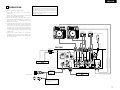
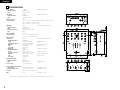
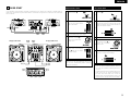
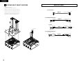
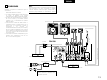
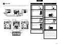
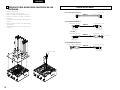
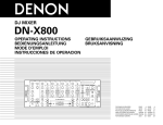
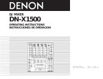
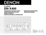
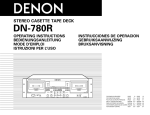
DJ MIXER
DN-X100
OPERATING INSTRUCTIONS
INSTRUCCIONES DE OPERACION
FOR ENGLISH READERS
PAGE
5 ~ PAGE
10
PARA LECTORES DE ESPAÑOL
PAGINA 11 ~ PAGINA 16
SAFETY INSTRUCTIONS
CAUTION
1.
Read Instructions – All the safety and operating instructions
should be read before the product is operated.
2.
Retain Instructions – The safety and operating instructions
should be retained for future reference.
3.
Heed Warnings – All warnings on the product and in the
operating instructions should be adhered to.
4.
Follow Instructions – All operating and use instructions
should be followed.
5.
Cleaning – Unplug this product from the wall outlet before
cleaning. Do not use liquid cleaners or aerosol cleaners.
The lightning flash with arrowhead symbol, within an equilateral triangle, is intended to
alert the user to the presence of uninsulated “dangerous voltage” within the product’s
enclosure that may be of sufficient magnitude to constitute a risk of electric shock to
persons.
6.
Attachments – Do not use attachments not recommended
by the product manufacturer as they may cause hazards.
7.
Water and Moisture – Do not use this product near water –
for example, near a bath tub, wash bowl, kitchen sink, or
laundry tub; in a wet basement; or near a swimming pool;
and the like.
The exclamation point within an equilateral triangle is intended to alert the user to the
presence of important operating and maintenance (servicing) instructions in the literature
accompanying the appliance.
8.
Accessories – Do not place this product on an unstable cart,
stand, tripod, bracket, or table. The product may fall,
causing serious injury to a child or adult, and serious
damage to the product. Use only with a cart, stand, tripod,
bracket, or table recommended by the manufacturer, or
sold with the product. Any mounting of the product should
follow the manufacturer’s instructions, and should use a
mounting accessory
recommended by the
manufacturer.
RISK OF ELECTRIC SHOCK
DO NOT OPEN
CAUTION: TO REDUCE THE RISK OF ELECTRIC SHOCK, DO NOT REMOVE COVER (OR
BACK). NO USER SERVICEABLE PARTS INSIDE. REFER SERVICING TO
QUALIFIED SERVICE PESONNEL.
WARNING: TO
PREVENT FIRE OR SHOCK HAZARD, DO NOT EXPOSE THIS
APPLIANCE TO RAIN OR MOISTURE.
9.
CAUTION:
LABELS:
1. Handle the power supply cord carefully
Do not damage or deform the power supply cord. If it
is damaged or deformed, it may cause electric shock
or malfunction when used. When removing from wall
outlet, be sure to remove by holding the plug
attachment and not by pulling the cord.
2. Do not open the top cover
In order to prevent electric shock, do not open the top
cover.
If problems occur, contact your DENON dealer.
3. Do not place anything inside
Do not place metal objects or spill liquid inside the DJ
mixer.
Electric shock or malfunction may result.
Please, record and retain the Model name and serial
number of your set shown on the rating label.
Model No. DN-X100
Serial No.
CAUTION
TO PREVENT ELECTRIC SHOCK, MATCH
WIDE BLADE OF PLUG TO WIDE SLOT,
FULLY INSERT.
ATTENTION
POUR ÉVITER LES CHOCS ÉLECTRIQUES,
INTERODUIRE LA LAME LA PLUS LARGE
DE LA FICHE DANS LA BORNE
CORRESPONDANTE DE LA PRISE ET
POUSSER JUSQU’ AU FOND.
A product and cart
combination should be
moved with care. Quick
stops, excessive force,
and uneven surfaces may
cause the product and cart
combination to overturn.
11. Power Sources – This product should be operated only
from the type of power source indicated on the marking
label. If you are not sure of the type of power supply to
your home, consult your product dealer or local power
company. For products intended to operate from battery
power, or other sources, refer to the operating instructions.
12. Grounding or Polarization – This product may be equipped
with a polarized alternating-current line plug (a plug having
one blade wider than the other). This plug will fit into the
power outlet only one way. This is a safety feature. If you
are unable to insert the plug fully into the outlet, try
reversing the plug. If the plug should still fail to fit, contact
your electrician to replace your obsolete outlet. Do not
defeat the safety purpose of the polarized plug.
ANTENNA
LEAD IN
WIRE
GROUND
CLAMP
ANTENNA
DISCHARGE UNIT
(NEC SECTION 810-20)
ELECTRIC
SERVICE
EQUIPMENT
GROUNDING CONDUCTORS
(NEC SECTION 810-21)
GROUND CLAMPS
POWER SERVICE GROUNDING
ELECTRODE SYSTEM
(NEC ART 250, PART H)
NEC - NATIONAL ELECTRICAL CODE
15. Outdoor Antenna Grounding – If an outside antenna or
cable system is connected to the product, be sure the
antenna or cable system is grounded so as to provide some
protection against voltage surges and built-up static
charges. Article 810 of the National Electrical Code,
ANSI/NFPA 70, provides information with regard to proper
grounding of the mast and supporting structure, grounding
of the lead-in wire to an antenna discharge unit, size of
grounding conductors, location of antenna-discharge unit,
connection to grounding electrodes, and requirements for
the grounding electrode. See Figure A.
16. Lightning – For added protection for this product during a
lightning storm, or when it is left unattended and unused
for long periods of time, unplug it from the wall outlet and
disconnect the antenna or cable system. This will prevent
damage to the product due to lightning and power-line
surges.
17. Power Lines – An outside antenna system should not be
located in the vicinity of overhead power lines or other
electric light or power circuits, or where it can fall into such
power lines or circuits. When installing an outside antenna
system, extreme care should be taken to keep from
touching such power lines or circuits as contact with them
might be fatal.
18. Overloading – Do not overload wall outlets, extension
cords, or integral convenience receptacles as this can result
in a risk of fire or electric shock.
10. Ventilation – Slots and openings in the cabinet are provided
for ventilation and to ensure reliable operation of the
product and to protect it from overheating, and these
openings must not be blocked or covered. The openings
should never be blocked by placing the product on a bed,
sofa, rug, or other similar surface. This product should not
be placed in a built-in installation such as a bookcase or rack
unless proper ventilation is provided or the manufacturer’s
instructions have been adhered to.
FIGURE A
EXAMPLE OF ANTENNA GROUNDING
AS PER NATIONAL
ELECTRICAL CODE
13. Power-Cord Protection – Power-supply cords should be
routed so that they are not likely to be walked on or pinched
by items placed upon or against them, paying particular
attention to cords at plugs, convenience receptacles, and
the point where they exit from the product.
19. Object and Liquid Entry – Never push objects of any kind
into this product through openings as they may touch
dangerous voltage points or short-out parts that could
result in a fire or electric shock. Never spill liquid of any
kind on the product.
20. Servicing – Do not attempt to service this product yourself
as opening or removing covers may expose you to
dangerous voltage or other hazards. Refer all servicing to
qualified service personnel.
21. Damage Requiring Service – Unplug this product from the
wall outlet and refer servicing to qualified service personnel
under the following conditions:
a) When the power-supply cord or plug is damaged,
b) If liquid has been spilled, or objects have fallen into the
product,
c) If the product has been exposed to rain or water,
d) If the product does not operate normally by following
the operating instructions. Adjust only those controls
that are covered by the operating instructions as an
improper adjustment of other controls may result in
damage and will often require extensive work by a
qualified technician to restore the product to its normal
operation,
e) If the product has been dropped or damaged in any way,
and
f) When the product exhibits a distinct change in
performance – this indicates a need for service.
22. Replacement Parts – When replacement parts are required,
be sure the service technician has used replacement parts
specified by the manufacturer or have the same
characteristics as the original part.
Unauthorized
substitutions may result in fire, electric shock, or other
hazards.
23. Safety Check – Upon completion of any service or repairs
to this product, ask the service technician to perform safety
checks to determine that the product is in proper operating
condition.
24. Wall or Ceiling Mounting – The product should be mounted
to a wall or ceiling only as recommended by the
manufacturer.
25. Heat – The product should be situated away from heat
sources such as radiators, heat registers, stoves, or other
products (including amplifiers) that produce heat.
2
ENGLISH
ESPAÑOL
TOP PANEL DIAGRAM / DIAGRAMA DEL PANEL SUPERIOR
REAR PANEL DIAGRAM / DIAGRAMA DEL PANEL POSTERIOR
r
ty u u y t
e
r
@0
!9
!8
i
o
w
!0
q
!7
!6
!3
!1
!2
!3
!5
@7
@6
@5 @4 @3 @2 @5 @4 @3 @2
@1
FRONT PANEL DIAGRAM / DIAGRAMA DEL PANEL FRONTAL
@8
@9
#2
#1 #4
@9
@8
!4
3
#3 #2
#1
#0
NOTE ON USE / HINWEISE ZUM GEBRAUCH /
OBSERVATIONS RELATIVES A L’UTILISATION / NOTE SULL’USO
NOTAS SOBRE EL USO / ALVORENS TE GEBRUIKEN / OBSERVERA
• Avoid high temperatures.
Allow for sufficient heat dispersion when
installed on a rack.
• Vermeiden Sie hohe Temperaturen.
Beachten Sie, daß eine ausreichend
Luftzirkulation gewährleistet wird, wenn das
Gerät auf ein Regal gestellt wird.
• Eviter des températures élevées
Tenir compte d’une dispersion de chaleur
suffisante lors de l’installation sur une
étagère.
• Evitate di esporre l’unità a temperature alte.
Assicuratevi che ci sia un’adeguata
dispersione del calore quando installate
l’unità in un mobile per componenti audio.
• Evite altas temperaturas
Permite la suficiente dispersión del calor
cuando está instalado en la consola.
• Vermijd hoge temperaturen.
Zorg voor een degelijk hitteafvoer indien het
apparaat op een rek wordt geplaatst.
• Undvik höga temperaturer.
Se till att det finns möjlighet till god
värmeavledning vid montering i ett rack.
• Handle the power cord carefully.
Hold the plug when unplugging the cord.
• Gehen Sie vorsichtig mit dem Netzkabel um.
Halten Sie das Kabel am Stecker, wenn Sie
den Stecker herausziehen.
• Manipuler le cordon d’alimentation avec
précaution.
Tenir la prise lors du débranchement du
cordon.
• Manneggiate il filo di alimentazione con cura.
Agite per la spina quando scollegate il cavo
dalla presa.
• Maneje el cordón de energía con cuidado.
Sostenga el enchufe cuando desconecte el
cordón de energía.
• Hanteer het netsnoer voorzichtig.
Houd het snoer bij de stekker vast wanneer
deze moet worden aan- of losgekoppeld.
• Hantera nätkabeln varsamt.
Håll i kabeln när den kopplas från el-uttaget.
• Keep the set free from moisture, water, and
dust.
• Halten Sie das Gerät von Feuchtigkeit,
Wasser und Staub fern.
• Protéger l’appareil contre l’humidité, l’eau et
lapoussière.
• Tenete l’unità lontana dall’umidità, dall’acqua
e dalla polvere.
• Mantenga el equipo libre de humedad, agua
y polvo.
• Laat geen vochtigheid, water of stof in het
apparaat binnendringen.
• Utsätt inte apparaten för fukt, vatten och
damm.
• Unplug the power cord when not using the
set for long periods of time.
• Wenn das Gerät eine längere Zeit nicht
verwendet werden soll, trennen Sie das
Netzkabel vom Netzstecker.
• Débrancher le cordon d’alimentation lorsque
l’appareil n’est pas utilisé pendant de
longues périodes.
• Disinnestate il filo di alimentazione quando
avete l’intenzione di non usare il filo di
alimentazione per un lungo periodo di tempo.
• Desconecte el cordón de energía cuando no
utilice el equipo por mucho tiempo.
• Neem altijd het netsnoer uit het stopkontakt
wanneer het apparaat gedurende een lange
periode niet wordt gebruikt.
• Koppla ur nätkabeln om apparaten inte
kommer att användas i lång tid.
✽ (For sets with ventilation holes)
• Do not obstruct the ventilation holes.
• Die Belüftungsöffnungen dürfen nicht
verdeckt werden.
• Ne pas obstruer les trous d’aération.
• Non coprite i fori di ventilazione.
• No obstruya los orificios de ventilación.
• De ventilatieopeningen mogen niet worden
beblokkeerd.
• Täpp inte till ventilationsöppningarna.
CAUTION
• The ventilation should not be impeded by covering the
ventilation openings with items, such as newspapers,
table-cloths, curtains, etc.
• No naked flame sources, such as lighted candles,
should be placed on the apparatus.
4
• Do not let foreign objects in the set.
• Keine fremden Gegenstände in das Gerät
kommen lassen.
• Ne pas laisser des objets étrangers dans
l’appareil.
• E’ importante che nessun oggetto è inserito
all’interno dell’unità.
• No deje objetos extraños dentro del equipo.
• Laat geen vreemde voorwerpen in dit
apparaat vallen.
• Se till att främmande föremål inte tränger in i
apparaten.
• Do not let insecticides, benzene, and thinner
come in contact with the set.
• Lassen Sie das Gerät nicht mit Insektiziden,
Benzin
oder
Verdünnungsmitteln
in
Berührung kommen.
• Ne pas mettre en contact des insecticides,
du benzène et un diluant avec l’appareil.
• Assicuratevvi che l’unità non venga in
contatto con insetticidi, benzolo o solventi.
• No permita el contacto de insecticidas,
gasolina y diluyentes con el equipo.
• Laat geen insektenverdelgende middelen,
benzine of verfverdunner met dit apparaat in
kontakt komen.
• Se till att inte insektsmedel på spraybruk,
bensen och thinner kommer i kontakt med
apparatens hölje.
• DECLARATION OF CONFORMITY
We declare under our sole responsibility that this
product, to which this declaration relates, is in
conformity with the following standards:
EN60065, EN55013, EN55020, EN61000-3-2 and
EN61000-3-3.
Following the provisions of 73/23/EEC,
89/336/EEC and 93/68/EEC Directive.
• ÜBEREINSTIMMUNGSERKLÄRUNG
Wir erklären unter unserer Verantwortung, daß
dieses Produkt, auf das sich diese Erklärung
bezieht, den folgenden Standards entspricht:
EN60065, EN55013, EN55020, EN61000-3-2 und
EN61000-3-3.
Entspricht den Verordnungen der Direktive
73/23/EEC, 89/336/EEC und 93/68/EEC.
• DECLARATION DE CONFORMITE
Nous déclarons sous notre seule responsabilité
que l’appareil, auquel se réfère cette déclaration,
est conforme aux standards suivants:
EN60065, EN55013, EN55020, EN61000-3-2 et
EN61000-3-3.
D’après les dispositions de la Directive
73/23/EEC, 89/336/EEC et 93/68/EEC.
• DICHIARAZIONE DI CONFORMITÀ
Dichiariamo con piena responsabilità che questo
prodotto, al quale la nostra dichiarazione si
riferisce, è conforme alle seguenti normative:
EN60065, EN55013, EN55020, EN61000-3-2 e
EN61000-3-3.
In conformità con le condizioni delle direttive
73/23/EEC, 89/336/EEC e 93/68/EEC.
QUESTO PRODOTTO E’ CONFORME
AL D.M. 28/08/95 N. 548
• DECLARACIÓN DE CONFORMIDAD
Declaramos
bajo
nuestra
exclusiva
responsabilidad que este producto al que hace
referencia esta declaración, está conforme con
los siguientes estándares:
EN60065, EN55013, EN55020, EN61000-3-2 y
EN61000-3-3.
Siguiendo las provisiones de las Directivas
73/23/EEC, 89/336/EEC y 93/68/EEC.
• EENVORMIGHEIDSVERKLARING
Wij
verklaren
uitsluitend
op
onze
verantwoordelijkheid dat dit produkt, waarop
deze
verklaring
betrekking
heeft,
in
overeenstemming is met de volgende normen:
EN60065, EN55013, EN55020, EN61000-3-2 en
EN61000-3-3.
Volgens de bepalingen van de Richtlijnen
73/23/EEC, 89/336/EEC en 93/68/EEC.
• ÖVERENSSTÄMMELSESINTYG
Härmed intygas helt på eget ansvar att denna
produkt, vilken detta intyg avser, uppfyller
följande standarder:
EN60065, EN55013, EN55020, EN61000-3-2 och
EN61000-3-3.
Enligt stadgarna i direktiv 73/23/EEC, 89/336/EEC
och 93/68/EEC.
FCC INFORMATION (For US customers)
• Never disassemble or modify the set in any
way.
• Versuchen Sie niemals das Gerät
auseinander zu nehmen oder auf jegliche Art
zu verändern.
• Ne jamais démonter ou modifier l’appareil
d’une manière ou d’une autre.
• Non smontate mai, nè modificate l’unità in
nessun modo.
• Nunca desarme o modifique el equipo de
ninguna manera.
• Nooit dit apparaat demonteren of op andere
wijze modifiëren.
• Ta inte isär apparaten och försök inte bygga
om den.
• Please be care the environmental aspects of battery
disposal.
• The apparatus shall not be exposed to dripping or
splashing for use.
• No objects filled with liquids, such as vases, shall be
placed on the apparatus.
1. PRODUCT
3. NOTE
This product complies with Part 15 of the
FCC Rules. Operation is subject to the
following two conditions: (1) this product
may not cause harmful interference, and (2)
this product must accept any interference
received, including interference that may
cause undesired operation.
This product has been tested and found to comply with the limits for
a Class B digital device, pursuant to Part 15 of the FCC Rules. These
limits are designed to provide reasonable protection against harmful
interference in a residential installation.
This product generates, uses and can radiate radio frequency energy
and, if not installed and used in accordance with the instructions, may
cause harmful interference to radio communications. However, there
is no guarantee that interference will not occur in a particular
installation. If this product does cause harmful interference to radio or
television reception, which can be determined by turning the product
OFF and ON, the user is encouraged to try to correct the interference
by one or more of the following measures:
• Reorient or relocate the receiving antenna.
• Increase the separation between the equipment and receiver.
• Connect the product into an outlet on a circuit different from that
to which the receiver is connected.
• Consult the local retailer authorized to distribute this type of
product or an experienced radio/TV technician for help.
2. IMPORTANT NOTICE:
DO NOT MODIFY THIS PRODUCT
This product, when installed as indicated in
the instructions contained in this manual,
meets FCC requirements. Modification not
expressly approved by DENON may void
your authority, granted by the FCC, to use
the product.
ENGLISH
2 INTRODUCTION
2 PART NAMES AND FUNCTIONS
Thank you very much for purchasing the DENON DN-X100 DJ MIXER.
DENON proudly presents this advanced DJ MIXER to audiophiles and music lovers as a further proof of DENON’s
non-compromising pursuit of the ultimate in sound quality. The high quality performance and easy operation are
certain to provide you with many hours of outstanding listening pleasure.
(1) Top panel
– TABLE OF CONTENTS –
z
x
c
MAIN FEATURES ...............................................5
PART NAMES AND FUNCTIONS ...................5, 6
CONNECTIONS ..................................................7
2 ACCESSORIES
Please check to make sure the following items
are included with the main unit in the carton:
v
b
n
SPECIFICATIONS................................................8
FADER START ....................................................9
ROTATING INPUT SELECT SWITCHES ...........10
2. VCA controlled Channel Fader and Crossfader
3. Channel Fader and Crossfader contour adjustable
This feature allows adjusting the “shape” of the
Crossfader and Channel fader response from a
gentle curve for smooth to the steep pitch
required for top performance cut and scratch
effects.
4. Channel Fader and Crossfader Reverse
5. Channel Fader and Crossfader Start
The CD player can be started or stopped simply by
increasing or decreasing the level of the Ch.fader
or by using the Crossfader left to right or right to
left. (This function can only be used when the
DENON CD players DN-S3000, DN-S5000, DNS1000 or etc. is connected to the DN-X100.)
• When TALKOVER is selected , all signals except
the microphone level are decreased by 20 dB.
When at the ON or OFF position all signals
remain at their standard levels.
w MIC EQ controls
• Contour the frequency response of the Mic
input –12 dB to +12 dB.
• At the center position, sound is flat.
e MIC LEVEL control
q Operating instructions.......................................1
w AC adaptor ........................................................1
(AA-26 : for AC 120 V, AA-27 : for AC 230 V)
1 MAIN FEATURES
1. 2-Channel DJ Mixer
4 LINE, 2 PHONO, 1 Microphone systems and 2
MASTER outputs are provided independently.
q MIC ON/OFF/TALKOVER switch
6. Channel Reverse function
This function allows the left hand channel fader or
right hand channel fader to control PGM1 or
PGM2.
7. 3-Band Equalizer/Gain
LOW, MID, HI and GAIN controls are available on
every input channel.
8. 4 direction placement for input selector
9. Microphone Talkover function
• Adjust the level of Mic signal.
r Source EQ controls
• Contour the frequency response of the selected
inputs.
HI and MID:
• Adjusts the high-tone and mid-tone sound –40
dB to +10 dB.
LOW:
• Adjusts the high-tone and mid-tone sound –40
dB to +6 dB.
NOTE:
Clipping may occur if adjustments are set to
harsh.
t Input select switch
• Switches between the PHONO/LINE and LINE
inputs.
• When the lever of switch is vertical position, the
LINE2 or LINE4 input is selected.
• When the lever of switch is slope, the
PHONO1/LINE1 or PHONO2/lINE3 input is
selected.
• You can perform 4 direction placement. See
page 10.
y CUE buttons
• These buttons are used to activates a channels
“CUE” mode, the LED above the cue button
will glow when cue mode is activated. Cue
mode will send a channels incoming signal to
the headphones.
(Refer to page 3.)
u GAIN
• Adjusts the gain of each input channel.
i MASTER LEVEL control
• Adjust the level of the MASTER output.
o MASTER BALANCE control
• Adjust the L/R balance of the MASTER outputs.
!0 Headphone PAN control
• This function allows you to monitor the CUE
level as well as the MASTER output in your
headphones. A CUE Level may only be
monitored of the CUE signal is selected.
• Serves two purposes…In the STEREO mode it
changes the relative levels of the CUE and
MASTER mixed together in both ear cups. In
the SPLIT CUE mode it changes the balance
between the monaural CUE sound in the left
and monaural MASTER sound in the right.
!1 PHONES LEVEL control
• Adjusts the headphone output level.
!2 SPLIT CUE button
• In the STEREO mode, the stereo sound of
MASTER and CUE are fed to both ear cups. In
the SPLIT CUE mode, the headphone circuit
provides monaural CUE sound to the left and
monaural MASTER sound to the right.
• When the Level Meter mode select switch is
set to “MASTER”…In the STEREO mode, the
meter indicates the stereo level in the L/R
Master output. In the SPLIT CUE mode, the
monaural CUE sound level is displayed on the
left and the monaural MASTER sound level is
displayed on the right.
• In the SPRIT CUE mode, the LED is lit.
!3 Channel Fader
• Controls the channel output level.
5
ENGLISH
!4 Crossfader
• Fades the overall mixer output between
channels 1 and 2.
(2) Rear panel
!8 Power operation switch (POWER)
• Selects power “ON” or “OFF”.
!5 Level Meter
• The dual LED's indicators are used to detail
either the master output level, a combination of
the master output level and the CUE signal
level, or the PGM1/2 monaural level.
!6 CH REVERSE button
• This switch allows the left hand fader or right
hand fader to control PGM1 or PGM2.
• When the CH REVERSE mode is ON, the CH1
fader will be able to control PGM 2 sound and
the CH2 fader will be able to control PGM 1
sound..
NOTE:
• Please don’t confuse with the CH 1/2 FADER
REVERSE switch (#2).
!7 Level meter mode select switch
• The position of this switch will determine the
Level Meter mode. In the “MASTER” position,
the meter will detail the out level of the left and
right channels. In the “PGM 1/2” position, the
left side of the meter will indicate monaural
level of the PGM 1 and the right side of the
meter will indicate monaural level of the PGM 2.
NOTE:
Whenever the power switch is in the OFF state,
the AC adaptor is still connected on AC line
voltage. Please be sure to unplug the cord when
you don’t use for along time.
!9 Balanced MASTER OUT jacks (BAL.)
• These 1/4” TRS jacks provide a balanced line
level output.
• Connect these jacks to the balanced analog
input jacks on an amplifier or console.
• Pin layout: Tip=Hot Ring=Cold Sleeve=GND
@0 MIC BALANCED INPUT jack
• Accepts an balanced microphone with 1/4” TRS
mono jacks.
• Pin layout: Tip=Hot Ring=Cold Sleeve=GND
@1 PGM1, 2 FADER output jacks
• Connect these jacks to the FADER input jacks of
DN-S3000, DN-S5000, DN-S1000 and etc. using
the 3.5mm stereo mini cord.
@2 Phono ground screw (GND)
• This screws provide a place to connect the
ground wire from a turntable.
• This terminal is exclusively for a turntable
ground and not a safety earth ground.
@3 PHONO1, 2 / LINE1, 3 switches
(LN / PH)
• These switches change the input from PHONO
to a LINE level input.
• These switches set a LINE level input when
turntable is not connected.
NOTE:
Always be sure main power is shut off before
change the position of the Line Level Selector
Switch.
6
(3) Front panel
@4 PHONO1, 2 / LINE1, 3 input jacks
• These stereo pair of unbalanced RCA jacks are
inputs for a PHONO (RIAA) stage for magnetic
(MM) cartridges or a LINE stage suitable for any
device, such as a CD player.
@5 LINE2, 4 input jacks
• These stereo pair of unbalanced RCA jacks are
inputs for any line level device.
@6 Unbalanced MASTER OUT jacks
• This stereo pair of RCA jacks provides an
unbalanced line level output.
• Connect these jacks to the unbalanced analog
input jacks on an amplifier or console.
@7 AC IN
• Input connection for the included AC adaptor.
NOTE:
Use specified attached AC adaptor only.
@8 CH 1/2 FADER START switches
• Use this to switch the Channel Fader Start
function ON and OFF.
@9 CROSSFADER START A/B switches
• Use this to switch the Crossader Start function
ON and OFF.
#0 HEADPHONE output jack
• Accept 1/4” stereo headphone plugs.
#1 CH 1/2 FADER CONTOUR adjustment
• Adjusts the curve of the CH1/2 faders between
fast, normal , or slow fade.
#2 CH 1/2 FADER REVERSE switch
• Reverses the direction of each respective input
CH1/2 fader.
#3 CROSSFADER CONTOUR adjustment
• Adjusts the shape of the crossfader curve from
a fast cut for scratching or to a slow fade for
mixing.
#4 CROSSFADER REVERSE switch
• Reverses the direction of the crossfader.
ENGLISH
CD player
CD player
ON
POWER
ON
POWER
OFF
OFF
TITLE
TITLE
FLIP
A1
CLR
A
A2
B
FLIP
A1
CLR
A
A2
B
BPM
BPM
MEMO
TITLE
NEXT TR.
/B TRIM
PRESET
EXIT/
RELOOP
PARAMETERS
PUSH
MEMO
TITLE
NEXT TR.
/B TRIM
PRESET
QUICK JUMP
EXIT/
RELOOP
PARAMETERS
PUSH
QUICK JUMP
TIME
TIME
CONT.
/SINGLE
CONT.
/SINGLE
FAST SEARCH
FAST SEARCH
ECHO
/LOOP
TAP
AUTO
TRACK SEARCH
MP3 SEARCH MODE
ECHO
/LOOP
TAP
AUTO
FLANGER
TRACK SEARCH
MP3 SEARCH MODE
FLANGER
FILTER
FILTER
ON : SCRATCH
OFF : SEARCH/
BEND
DRAG-S
0
3
3
4
0
4
DRAG-S
Turntable 1
Turntable 2
DISC MODE
DISC MODE
ON : SCRATCH
OFF : SEARCH/
BEND
ANTI-S
2
2
3 210
Balanced microphone
1
1
4
BRAKE
765
ANTI-S
TING
KA
TING
KA
BRAKE
765
0
0
RVS
KEY ADJUST
KEY ADJUST
RVS
PITCH
PITCH
-12
-12
SLOW
BRAKE
SLOW
BRAKE
CUE
CUE
Quartz
Quartz
0
0
ON
OFF
POWER
ON
OFF
POWER
+12
+12
START
/STOP
START
/STOP
CUE/STUTTER
78
33
CUE/STUTTER
78
33
DP-DJ151 Digital
45
DP-DJ151 Digital
45
PITCH/KEY
PITCH/KEY
DISC EJECT
PLAY/PAUSE
RANGE
PITCH BEND
PLAY/PAUSE
RANGE
DISC EJECT
PITCH BEND
1/4” TRS
mono jack
1. Make certain AC power is off while making
connections.
2. Quality cables make a big difference in fidelity and
punch. Use high-quality, audio cables.
3. Do not use excessively long cables. Be sure plugs
and jacks are securely fastened. Loose connections
cause hum, noise, or intermittents that could
damage your speakers.
4. Connect all stereo input sources. Then connect any
effects into the stereo effect, if used. Connect your
microphone(s) and monitor headphones. Make sure
all faders are at “zero” and the unit is off. Take care
to connect only one cable at a time. Pay attention to
L and R position of jacks, on both the DN-X100 and
outboard gear.
5. Connect the stereo outputs to the power
amplifier(s) and/or tape deck(s) and/or MD
recorder(s) and/or CD recorder(s). Plug the DN-X100
into AC power outlet.
3 210
Refer to the connection diagram below.
NOTE:
Always switch on your audio input sources such as
CD players first, then your mixer, and finally any
amplifiers. When turning off, always reverse this
operation by turning off amplifiers, then your mixer,
and then input units.
4
3 CONNECTIONS
DN-X100
1/4” TRS jack
R
L
L
R
R
L
L
R
L
Main balanced power amplifier
AA-26: for AC 120V
AA-27: for AC 230V
R
L
3.5 mm stereo mini cord
3.5 mm stereo mini cord
R
AA-26
or
AA-27
To power outlet
AC ADAPTOR
Main unbalanced power amplifier
Note:
Use specified attached AC
adaptor only.
7
ENGLISH
4 SPECIFICATIONS
• Phono Inputs:
Input Impedance
Level
2 Stereo
50 kΩ/kohms
–50 dBV (3 mV)
Unbalanced RCA jacks
• Line Inputs:
Input Impedance
Level
2 Stereo
20 kΩ/kohms
–14 dBV (200 mV)
Unbalanced RCA jacks
• EQ Control (Line):
Control Range
3 Bands
HI:
–30 dB to +10 dB (at 16 kHz), –38 dB to +10 dB (at 20 kHz)
MID: –38 dB to +10 dB (at 01 kHz)
LOW: –38 dB to +06 dB (at 060 Hz)
• Mic Inputs:
Input Impedance
Level
Frequency Response
S/N
1 Mono
2 kΩ/kohms
–54 dBV (2 mV)
20 Hz to 20 kHz (±3 dB)
66dB
• EQ Control (Mic):
Control Range
2 Bands
HI:
–12 to +12 dB (at 10 kHz)
LOW: –12 to +12 dB (at 100 Hz)
• Master Output:
Balanced
Output Impedance
Level
Frequency Response
THD+N
S/N
Cross Talk
Unbalanced
Output Impedance
Level
Frequency Response
THD+N
S/N
Cross Talk
Stereo
150 Ω/ohms
+4 dBm (1.23 Vrms)
20 Hz to 20 kHz (±2 dB)
LINE : Below 0.05 %
LINE : 85 dB
Over 75 dB
Stereo
1 kΩ/kohms
0 dBV (1 Vrms)V
20 Hz to 20 kHz (±2 dB)
LINE : Below 0.05 %
LINE : 85 dB
Over 75 dB
• Headphone Output:
Output Impedance
Level
Stereo
33 Ω/ohms
0 dBV (1 Vrms)
• Power Source:
AC 10 V 750 mA x 2
Active Balanced 1/4” TRS jack
Active Balanced 1/4” TRS jack
(600 Ω/ohms load)
PHONO : Below 0.07 %
PHONO : 76 dB
Unbalanced RCA jacks
(10 kΩ/ohms load)
PHONO : Below 0.07 %
PHONO : 76 dB
(32 Ω/ohms load)
• Power Supply, Consumptions:
USA, Canada
AC 120 V ± 10 %, 60 Hz
(AC adaptor : AA-26)
Europe, Asia, Oceania
AC 230 V ± 10 %, 50 Hz
(AC adaptor : AA-27)
• Unit Size
220 (W) x 226 (D) x 85.4 (H) mm
• Mass
2.8 kg
AC adaptor : 0.5 kg
✽ Specifications and design are subject to change without notice for purpose of improvement.
8
ENGLISH
5 FADER START
Channel Fader Start
If the separately sold DN-S5000, DN-S3000, DN-S1000 and etc. players are connected to FADER PGM1 or
PGM2, they can started using the Channel fader or Crossfader, as long as the 3.5 mm stereo mini cords have
been connected.
R
DEL NO.
DELE NO.
1
L
FADER
R
L
LINE4
CD player (DN-S1000)
FADER
PGM1
A1
A2
LINE
OUT
FADER
PGM2
FADER
PGM1
3
Set the standby mode on CD player.
4
Use the CH 1/2 FADER
CONTOUR controls #1 to
control the Channel fader
startup curve.
FADER
DN-X100
B
FLIP
BPM
CLR
MEMO
2
CD player (DN-S1000)
FADER
PGM2
FADER
FLIP
LINE2
CLR
MEMO
PRESET
PRESET
A1
EXIT/
RELOOP
1-MIN. SKIP
CONT.
/SINGLE
TAP
TAP
FLANGER
FLANGER
5
FILTER
DISC MODE
3
Set the standby mode on CD player.
4
Use the CROSS FADER
CONTOUR control #3 to
control the Crossfader
startup curve.
A2
TIME
CONT.
/SINGLE
Slide the Crossfader !4 all the way in direction
opposite the source you want to start. (In the
following example, startup is done with the CD
player connected to PGM1.)
2
FADER
R
1
Move the Channel fader !3 of
CH-1 or CH-2 control all the
way to the bottom.
MODEL NO.
MADE IN JAPAN FABRIQUE AU JAPO
LINE
OUT
Turn on the CROSSFADER START A, B
switches @9.
Turn on the CH 1/2 FADER
START switches @8.
R
DN-S1000
Crossfader Start
When you want to start the
player, move up the Channel
fader !3 and the CD player
will begin playing.
When the Crossfader !4 is slid in the opposite
direction, CD player play will begin.
0
BRAKE
BRAKE
RVS
5
RVS
CUE
PLAY/PAUSE
DISC EJECT
RANGE
DISC EJECT
PITCH BEND
(1)-2, 5
(2)-2, 5
(1)-2, 5
(2)-1
(1)-1
(2)-1
(1)-1
(1)-4
(2)-4
(1)-4
NOTE:
• When the CH 1/2 FADER REVERSE switch is set
to ON, the corresponding fader's operating
direction is reversed.
NOTES:
• When the CROSS FADER REVERSE switch is
set to ON, the Crossfader's operating direction is
reversed.
• Channel Fader Start and Crossfader Start for the
same source will not operate simultaneously.
You must select from either one. If both CH
FADER START and CROSSFADER START A, B
switches are ON, priority will be the Crossfader.
9
ENGLISH
6 ROTATING INPUT SELECT SWITCHES
About the Cables
1. Disconnect the power.
2. Remove knobs from the Top Panel.
3. Remove the 6 screws attaching the Top Panel.
(For RCA PINJACK)
4. Remove the 2 screws attaching the Switch unit.
RCA pin plug
Cable 1
5. Rotate the Switch unit to the desired location.
Unbalanced
6. Reinstall the 2 screws holding the Switch unit.
7. Reinstall the Top Panel and reattach knobs.
(For BALANCED MASTER OUT)
Balanced
Cable 2
Sleeve=GND
Ring=Cold
Tip=Hot
Balanced (1/4” TS)
Sleeve=GND
Ring=Cold
Tip=Hot
(For MIC)
Balanced (1/4” TRS)
Cable 3
Balanced
1=GND
2=Hot
Switch unit
XLR3-11C
Sleeve=GND
Ring=Cold
Tip=Hot
3=Cold
(For BALANCED MASTER OUT)
2=Hot 1=GND
3=Cold
10
Balanced
XLR3-12C
Cable 4
Balanced (1/4” TRS)
Sleeve=GND
Ring=Cold
Tip=Hot
ESPAÑOL
2 INTRODUCCIÓN
2 NOMBRES Y FUNCIONES DE PARTES
Gracias por haber adquirido el reproductor de DENON DN-X100 DJ MIXER.
DENON se siente orgulloso de presentar este avanzado DJ MIXER para los aficionados y amantes de la música
como una prueba más de la búsqueda sin obligaciones de DENON de lo último en calidad de sonido. El
rendimiento de alta calidad y la fácil operación sin duda le proporcionarán muchas horas de deleite con una
escucha excepcional.
– CONTENDIO –
z
x
c
v
FUNCIONES PRINCIPALES..............................29
NOMBRES Y FUNCIONES DE PARTES ......29, 30
CONEXIONES...................................................31
b
n
FADER START ..................................................33
INTERRUPTORES SELECTORES
GIRATORIOS DE LAS ENTRADAS...................34
ESPECIFICACIONES ........................................32
2 ACCESSORIOS
Compruebe que los siguientes elementos se
encuentran en la caja junto con la unidad
principal:
(1) Panel superior
q Interruptor MIC ON/OFF/TALKOVER
• Cuando la opción TALKOVER está seleccionada,
todas las señales, excepto el nivel del
micrófono, disminuirán 20 dB. Cuando está en
la posición ON u OFF, todas las señales
permanecerán en los niveles estándar.
w Controles de MIC EQ
• Modela la respuesta de frecuencia de la entrada
de Micrófono Principal de –12 dB a +12 dB.
• En la posición central el sonido será plano.
q Instrucciones de operación...............................1
w Adaptador de CA...............................................1
(AA-26 : para CA 120 V, AA-27 : para CA 230 V)
e Controle de MIC LEVEL
• Ajusta el nivel de la señal Mic.
r Controles de EQ de la fuente
01. DJ Mixer bicanal
Se suministran 4 LÍNEAS, 2 PHONO, 1 sistema de
micrófono y 2 salidas MASTER independientes.
06. Función de inversión de canal
Esta función permite al atenuador de canal
izquierdo o derecho controlar el PGM1 o el PGM2.
• Modela la respuesta de frecuencia de las
entradas seleccionadas.
HI y MID:
• Ajuste el sonido de tono alto y de tono medio
entre –40 dB y +10 dB.
LOW:
• Ajusta el sonido de registros graves de –40 dB a
+6 dB.
02. Crossfader (dispositivo de atenuación cruzada)
y atenuador de canal controlados mediante un
atenuador controlado por voltaje
07. Ecualizador/Ganancia de 3 bandas
Los controles LOW, MID, HI y GAIN están
disponibles para todos los canales de entrada.
NOTA:
Si el ajuste se realiza a muy agudo puede
producirse saturación.
03. Curva ajustable del crossfader y el atenuador
de canal
Esta característica permite ajustar la “forma” de la
respuesta del crossfader y el atenuador de canal
desde una curva suave para conseguir
deslizamientos largos, hasta el tono abrupto
necesario para efectos de cortes de actuaciones
de alta calidad y efectos de rayado.
08. Posición en 4 direcciones para el selector de
entrada
1 FUNCIONES PRINCIPALES
04. Función de inversión del crossfader y el
atenuador de canal
05. Comienzo de Fader y Comienzo de Crossfader
El reproductor de CD puede ponerse en marcha y
detenerse
simplemente
aumentando
o
disminuyendo el nivel del fader de Ch. o con el
fader de cruce de izquierda a derecha a o de
derecha a izquierda. (Esta función sólo puede
utilizarse cuando los reproductores de CD de
DENON DN-S3000, DN-S5000, DN-S1000 u otros
están conectados a la unidad DN-X100.)
09. Función de micrófono Talkover
(Fate riferimento alla pagina 3.)
t Interruptor selector de entrada
• Alterna entre las entradas PHONO/LINE y LINE.
• Cuando la palanca del interruptor está en
posición vertical, estará seleccionada la entrada
LINE2 o LINE4.
• Cuando la palanca del interruptor esté inclinada,
estará seleccionada la entrada PHONO1/LINE1
o PHONO2/LINE3.
• Puede colocar la palanca en 4 posiciones.
Consulte la página 34
y Botones CUE
• Estos botones sirven para activar el modo de
canales “CUE”. El testigo encima del botón
“CUE” se iluminará cuando se active el modo
CUE. El modo CUE enviará una señal de entrada
de los canales a los auriculares.
u GAIN
• Ajusta la ganancia de cada canal de entrada.
i Controle de MASTER LEVEL
•Ajusta el nivel de las salidas MASTER.
o Controle de MASTER BALANCE
• Ajuste el balance L/R de las salidas MASTER.
!0 Controle de Headphone PAN
• Esta función le permite controlar el nivel de CUE
y la salida MASTER de sus auriculares. Sólo
podrá controlar un nivel de CUE si la señal CUE
está seleccionada.
• Tiene dos funciones: En el modo STEREO,
cambia los niveles relativos de CUE y MASTER
mezclados en ambos auriculares. En el modo
SPLIT CUE, cambia el balance entre el sonido
monoaural CUE en el auricular izquierdo y el
sonido monoaural MASTER en el derecho.
!1 Controle de PHONES LEVEL
• Ajusta el nivel de salida de los auriculares.
!2 Botón SPLIT CUE
• En el modo STEREO, el sonido estéreo de
MASTER y CUE se enviará a ambos auriculares.
En el modo SPLIT CUE, el circuito del auricular
suministrará sonido monoaural CUE al lado
izquierdo y sonido monoaural MASTER al
derecho.
• Cuando el interruptor selector del modo del
medidor de nivel está en la posición MASTERen
el modo STEREO, el medidor indicará el nivel
estéreo en la salida principal izquierda y
derecha. En el modo SPLIT CUE, el nivel de
sonido monoaural CUE se mostrará en el lado
izquierdo y el nivel de sonido monoaural
MASTER se mostrará en el lado derecho.
• En el modo SPLIT CUE, el DEL se iluminará.
!3 Canal Fader
• Controla el nivel de salida de los canales.
11
ESPAÑOL
!4 Crossfader
• Atenúa la salida del mezclador general entre los
canales 1 y 2.
!5 Medidor de nivel
• Los indicadores DEL duales se utilizan para
detallar el nivel de salida principal, una
combinación del nivel de salida principal y el
nivel de la señal CUE, o el nivel monoaural de
PGM1/2.
!6 Botón CH REVERSE
• Esta interruptor permite al atenuador izquierdo o
derecho controlar el PGM1 o el PGM2.
• Cuando el modo CH REVERSE (inversión de
canal) está en la posición ON, el atenuador del
canal 1 (CH1) podrá controlar el sonido del PGM
2, y el atenuador del canal 2 (CH2) podrá
controlar el sonido del PGM 1.
NOTA:
No debe confundirse con el interruptor #2 de la
función FADER REVERSE (inversión del
atenuador) de los canales 1 y 2.
!7 Interruptor selector del modo del
medidor de nivel
• La posición de este interruptor determinará el
modo del medidor de nivel. En la posición
“MASTER”, el medidor detallará el nivel de
salida de los canales izquierdo o derecho. En la
posición “PGM 1/2”, el lado izquierdo del
medidor indicará el nivel monoaural del PGM 1 y
el lado derecho, indicará el nivel monoaural del
PGM 2.
(2) Panel posterior
!8 Interruptor de funcionamiento de
@4 Terminales de entrada PHONO1, 2 /
alimentación (POWER)
LINE1, 3
• Coloca la unidad en “ON” o en “OFF”.
• Estos pares de terminales RCA no balanceados
son entradas para una etapa Fono (RIAA)
cápsulas (MM) magnéticas o una etapa de Línea
adecuada para cualquier dispositivo, como un
reproductor de CD.
NOTA:
Siempre que el interruptor de alimentación esté
en posición OFF, el adaptador de CA seguirá
estando conectado al voltaje de línea de CA.
Asegúrese de desenchufar el cable cuando no
deba utilizar la unidad durante un periodo de
tiempo prolongado.
!9 Terminales BALANCED MASTER
OUT
• Los conectores TRS de 1/4” pulgadas
proporcionan una salida de nivel equilibrado.
• Conecte estos conectores a los enchufes de
entrada analógica equilibrada de un amplificador
o consola.
• Disposición de los contactos:
Punta=Caliente Anillo=Fría Funda=GND
@0 Terminale MIC BALANCED INPUT
• Acepta un micrófono equilibrado con
conexiones modo TRS de 1/4”.
• Disposición de los contactos:
Punta=Caliente Anillo=Fría Funda=GND
@1 Terminales de salida PGM1, 2 FADER
• Conecte estas clavijas a las tomas de entrada
FADER de las unidades DN-S3000, DN-S5000,
DN-S1000, etc., utilizando un minicable estéreo
de 3,5 mm.
@2 Tornillo de Toma a Tierra de Fono
(GND)
• Estos tornillos permiten la conexión de un cable
de masa al plato.
• Este terminal es exclusivo para la masa de un
plato y no para una conexión a tierra de
seguridad.
@3 Interruptores PHONO1, 2 / LINE1, 3
(LN / PH)
• Estos interruptores cambian la Entrada de Fono
a una entrada de nivel de Línea.
• Estos interruptores ajustan las entradas de nivel
de línea cuando un tocadiscos no está
conectado.
NOTA:
Siempre debe comprobar que la unidad está
apagada antes de cambiar la posición del
interruptor selector del nivel de línea.
12
(3) Panel delantero
@5 Terminales de entrada LINE2, 4
• Estos pares de terminales RCA estéreo no
balanceados son entradas para cualquier
dispositivo de nivel de línea.
@6 Terminales UNBALANCED MASTER
OUT
• Este par de terminales RCA estéreo proporciona
una salida de nivel de línea no balanceada.
• Conecte estos terminales a los conectores de
entrada analógica no balanceada de un
amplificador o mesa de mezclas.
@7 AC IN (Entrada de alimentación)
• Conexión de entrada para el adaptador de CA
incluido.
NOTA:
Utilice únicamente el adaptador de CA acoplado
especificado.
@8 Interruptores CH 1/2 FADER START
• Utilice esta función para cambiar entre ON y
OFF en la función de inicio de atenuación de
canal.
@9 Interruptores CROSSFADER START
A, B
• Utilice esta opción para cambiar entre ON y OFF
en la función de inicio de crossfader.
#0 Toma de salida HEADPHONE
• Acepta conectores de auriculares estéreo de 1/4”.
#1 Ajuste de CH 1/2 FADER CONTOUR
• Ajusta la curva de los atenuadores de los
canales 1 y 2 entre atenuación rápida, normal o
lenta.
#2 Interruptor CH 1/2 FADER REVERSE
• Invierte la dirección de cada atenuador de
entrada de los canales 1 y 2.
#3 Ajuste de CROSSFADER CONTOUR
• Ajusta la forma de la curva del Crossfader desde
un apagado rápido para rayados hasta una
atenuación lenta para el mezclado.
#4 Interruptor CROSSFADER REVERSE
• Invierte la dirección del crossfader.
ESPAÑOL
Reproductor de CD
Reproductor de CD
ON
POWER
POWER
ON
OFF
OFF
TITLE
TITLE
FLIP
A1
CLR
A
A2
B
FLIP
A1
CLR
A
A2
B
BPM
BPM
MEMO
TITLE
NEXT TR.
/B TRIM
PRESET
EXIT/
RELOOP
PARAMETERS
PUSH
MEMO
TITLE
NEXT TR.
/B TRIM
PRESET
QUICK JUMP
EXIT/
RELOOP
PARAMETERS
PUSH
QUICK JUMP
TIME
TIME
CONT.
/SINGLE
CONT.
/SINGLE
FAST SEARCH
FAST SEARCH
AUTO
TRACK SEARCH
MP3 SEARCH MODE
ECHO
/LOOP
TAP
AUTO
TRACK SEARCH
MP3 SEARCH MODE
ECHO
/LOOP
TAP
FLANGER
FLANGER
FILTER
Plato giradiscos 2
FILTER
DISC MODE
DISC MODE
ON : SCRATCH
OFF : SEARCH/
BEND
DRAG-S
0
Plato giradiscos 1
3
3
0
4
DRAG-S
4
ON : SCRATCH
OFF : SEARCH/
BEND
ANTI-S
2
2
Micrófono balanceados
3 210
1
1
4
BRAKE
BRAKE
765
ANTI-S
TING
KA
TING
KA
765
0
0
RVS
KEY ADJUST
KEY ADJUST
RVS
PITCH
PITCH
-12
-12
SLOW
BRAKE
SLOW
BRAKE
CUE
CUE
Quartz
Quartz
0
0
ON
OFF
POWER
ON
OFF
POWER
+12
+12
START
/STOP
START
/STOP
CUE/STUTTER
78
33
CUE/STUTTER
78
33
DP-DJ151 Digital
45
DP-DJ151 Digital
45
PITCH/KEY
PITCH/KEY
DISC EJECT
PLAY/PAUSE
Terminal de
1/4” TRS
RANGE
PITCH BEND
PLAY/PAUSE
RANGE
DISC EJECT
PITCH BEND
Terminal mono de
1/4” TRS
DN-X100
R
L
L
R
R
L
L
R
L
Amplificador de potencia balanceado Principal
AA-26 : Para 120V de CA
AA-27 : Para 230V de CA
R
Cable estéreo mini de 3,5 mm
R
Cable estéreo mini de 3,5 mm
1. Asegúrese de que la alimentación de c.a. está
desactivada al realizar las conexiones.
2. Los cables de calidad implican una gran diferencia
en cuanto a la fidelidad y a la pegada
conseguidas.Utilice cables de audio de alta calidad.
3. No utilice cables excesivamente largos. Asegúrese
de que los enchufes y los terminales queden
firmemente sujetos.Las conexiones flojas provocan
zumbidos, ruidos o intermitencias que podrían
dañar los altavoces.
4. Conecte todas las fuentes de entrada estéreo. A
continuación conecte la unidad de efectos en el
Efecto estéreo, si se utiliza alguno. Conecte el
micrófono(s)
y
los
auriculares
de
monitorización.Asegúrese de que todos los mandos
deslizantes se encuentran en la posición “cero” y
de que la unidad está apagada. Procure conectar
sólo un cable por vez. Preste atención a la posición
R y L de los conectores, tanto en el DN-X100 como
en el equipo externo.
5. Conecte las salidas estéreo al amplificador(es) y/o la
platina(s) y/o el grabador(es) de MD y/o los
grabadores de CD. Enchufe el DN-X100 en la toma
de c.a. de la red eléctrica general.
3 210
Remítase al Diagrama de Conexión que figura a
continuación.
NOTA:
Encienda siempre primero las fuentes de entrada de audio tales
como reproductores CD, luego su mezclador, y finalmente
cualquier amplificador. Cuando lo apague, siempre realice la
operación inversa apagando los amplificadores, luego su
mezclador y luego las unidades de entrada.
4
3 CONEXIONES
L
AA-26
o
AA-27
A la toma de red eléctrica
Adaptador de CA
Amplificador de potencia no balanceado Principal
NOTA:
Utilice únicamente el adaptador de CA
acoplado especificado.
13
ESPAÑOL
4 ESPECIFICACIONES
• Entradas Phono:
Impedancia de entrada
Nivel
2 entradas estéreo
50 kΩ/kohmios
–50 dBV (3 mV)
Conexiones RCA no equilibradas
• Entradas de línea:
Impedancia de entrada
Nivel
2 entradas estéreo
20 kΩ/kohmios
–14 dBV (200 mV)
Conexiones RCA no equilibradas
• Control de EQ (Línea):
Intervalo de control
3 bandas
HI :
–30 dB hasta +10 dB (a 16 kHz), –38 dB hasta +10 dB (a 20 kHz)
MID : –38 dB hasta +10 dB (a 01 kHz)
LOW : –38 dB hasta +06 dB (a 060 Hz)
• Entradas Mic:
Impedancia de entrada
Nivel
Respuesta de frecuencia
S/N
1 entradas Mono
2 kΩ/kohmios
–54 dBV (2 mV)
20 Hz a 20 kHz (±3 dB)
66dB
• Control de EQ (Mic):
Intervalo de control
2 bandas
HI :
–12 hasta +12 dB (a 10 kHz)
LOW : –12 hasta +12 dB (a 100 Hz)
• Salida Master:
Equilibrada
Impedancia de salida
Nivel
Respuesta de frecuencia
THD+N
S/N
Diafonía
No equilibrada
Impedancia de salida
Nivel
Respuesta de frecuencia
THD+N
S/N
Diafonía
Entradas estéreo
150 Ω/ohmios
+4 dBm (1,23 Vrms)
20 Hz a 20 kHz (±2 dB)
LINE : Por debajo de 0,05 %
LINE : 85 dB
Más de 75 dB
Entradas estéreo
1 kΩ/kohmios
0 dBV (1 Vrms)
20 Hz a 20 kHz (±2 dB)
LINE : Por debajo de 0,05 %
LINE : 85 dB
Más de 75 dB
• Salida de auriculares:
Impedancia de salida
Nivel
Entradas estéreo
33 Ω/ohmios
0 dBV (1 Vrms)
• Fuente de alimentación:
CA 10 V 750 mA x 2
• Fuente de alimentación, consumos:
EE.UU. y Canadá
CA 120 V ± 10 %, 60 Hz
Europa, Asia, Oceanía
CA 230 V ± 10 %, 50 Hz
Conexion 1/4” TRS equilibrio activo
Conexion 1/4” TRS equilibrio activo
(Carga de 600 Ω/ohmios)
PHONO : Por debajo de 0,07 %
PHONO : 76 dB
Conexiones RCA no equilibradas
(Carga de 10 kΩ/kohmios)
PHONO : Por debajo de 0,07 %
PHONO : 76 dB
(Carga de 32 Ω/ohmios)
(Adaptador de CA : AA-26)
(Adaptador de CA : AA-27)
• Tamaño de unidad
220 (Anch) x 226 (Prof) x 85.4 (Alt) mm
• Peso
Unidat : 2,8 kg
Adaptador de CA : 0,5 kg
✽ Con el propósito de introducir mejoras, el diseño y las especificaciones del producto están
sujetos a cambios sin previo aviso.
14
ESPAÑOL
5 FADER START
Comienzo de Fader de Canal
Si los reproductores DN-S5000, DN-S3000, DN-S1000, etc., que se venden por separado, están conectados a
la LÍNEA 1, 2, 3 ó 4, pueden encenderse mediante el atenuador de entrada de fuente (Atenuador de canal) o
mediante el Crossfader, siempre y cuando se hayan conectado los minicables estéreo de 3,5 mm.
R
R
DN-S1000
MODEL NO.
MADE IN JAPAN FABRIQUE AU JAPO
2
LINE
OUT
L
FADER
R
L
LINE4
Reproductor de CD (DN-S1000)
FADER
PGM1
A1
A2
LINE2
LINE
OUT
FADER
PGM2
FADER
PGM1
FADER
PGM2
FADER
FLIP
3
Reproductor de CD (DN-S1000)
4
FADER
DN-X100
B
FLIP
BPM
CLR
MEMO
1
CLR
MEMO
PRESET
PRESET
A1
Deslice el Crossfader !4 a fondo en la dirección
opuesta a la fuente que desee dar comienzo.
(En el siguiente ejemplo, el inicio se realiza con
el reproductor de CD conectado al PGM1.)
Desplace el atenuador de
canal !3 del control del canal
1 o el canal 2 completamente
hacia abajo.
2
FADER
R
Pulse los interruptores A y B de CROSSFADER
START @9.
Pulse los interruptores CH 1/2 FADER START
@8 .
1
DEL NO.
DELE NO.
Comienzo de Crossfader
Establezca el modo Standby en el reproductor
de CD.
Utilice los controles #1 de
la función CH 1/2 FADER
CONTOUR para controlar
la curva de inicio del
atenuador de canal.
3
4
A2
EXIT/
RELOOP
Establezca el modo Standby en el reproductor
de CD.
Use el control de
CROSSFADER
CONTOUR #3 para
controlar la curva de
comienzo de crossfader.
1-MIN. SKIP
TIME
CONT.
/SINGLE
CONT.
/SINGLE
TAP
TAP
FLANGER
FLANGER
FILTER
DISC MODE
5
0
BRAKE
BRAKE
RVS
RVS
Cuando desee iniciar el
reproductor, suba el fader de
entrada de fuente (fader de
Ch.) !3 y el reproductor de CD
comenzará a reproducir.
Cuando el Crossfade !4 se desliza en el sentido
contrario, el reproductor de CD inicia su
funcionamiento.
5
CUE
PLAY/PAUSE
DISC EJECT
RANGE
DISC EJECT
PITCH BEND
(1)-2, 5
(2)-2, 5
(1)-2, 5
(2)-1
(1)-1
(2)-1
(1)-1
(1)-4
(2)-4
(1)-4
NOTA:
• Cuando el interruptor CH 1/2 FADER REVERSE
está en posición ON, la dirección de
funcionamiento del atenuador de canal se
invertirá.
NOTAS:
• Cuando el interruptor CROSSFADER REVERSE
está en posición ON, la dirección de
funcionamiento del Crossfader se invertirá.
• El comienzo de Fader de Canal y el Comienzo de
Fader de Cruce para la misma fuente no
funcionarán
simultáneamente.
Deberá
seleccionar uno de los dos. Si los interruptores
CH FADER START y CROSSFADER START A, B
están en la posición ON, la función que tendrá
prioridad será el crossfader.
15
ESPAÑOL
6 INTERRUPTORES SELECTORES GIRATORIOS DE LAS
Acerca de los cables
ENTRADAS
1. Desconecte la corriente.
(Para entrada RCA dentro/fuera)
2. Retire los botones del panel superior.
RCA pin plug
Cable 1
3. Retire los 6 tornillos que sujetan el panel superior.
No compensada
4. Retire los 2 tornillos que sujetan la unidad del
interruptor.
5. Haga girar la unidad del interruptor hasta la posición
deseada.
(Para BALANCED MASTER OUT)
6. Vuelva a montar los 2 tornillos que sujetan la unidad
del interruptor.
Compensada (1/4” TRS)
7. Vuelva a instalar el panel superior y acople de nuevo
los botones.
Cable 2
Funda=GND
Anillo=Fría
Punta=Caliente
Compensada (1/4” TRS)
Funda=GND
Anillo=Fría
Punta=Caliente
(Para MIC)
Compensada (1/4” TRS)
Cable 3
Compensada
1=GND
2=Caliente
XLR3-11C
Funda=GND
Anillo=Fría
Punta=Caliente
3=Fría
(Para BALANCED MASTER OUT)
2=Caliente 1=GND
3=Fría
Cambiar unidad
16
Compensada
XLR3-12C
Cable 4
Compensada (1/4” TRS)
Funda=GND
Anillo=Fría
Punta=Caliente
PROFESSIONAL BUSINESS COMPANY
7-35-1 Sagamiono, Sagamihara-shi, Kanagawa 228-8505, JAPAN