1
23186bk0.bk Page 3 Thursday, October 29, 1998 11:07 AM
'HOO 3UHFLVLRQ:RUN6WDWLRQ
'HVNWRS6\VWHPV
86(5·6*8,'(
ZZZGHOOFRP
23186bk0.bk Page 4 Thursday, October 29, 1998 11:07 AM
____________________
Information in this document is subject to change without notice.
© 1998 Dell Computer Corporation. All rights reserved.
Reproduction in any manner whatsoever without the written permission of Dell Computer Corporation is strictly forbidden.
Trademarks used in this text: Dell and the DELL logo are registered trademarks and DellWare is a registered service mark of Dell
Computer Corporation; Intel and Pentium are registered trademarks and MMX and Intel386 are trademarks of Intel Corporation;
Microsoft, MS-DOS, Windows, and Windows NT are registered trademarks of Microsoft Corporation; OS/2 is a registered trademark
of International Business Machines Corporation; UNIX is a registered trademark of UNIX System Laboratories, Inc., a wholly owned
subsidiary of Novell, Inc.; NetWare is a registered trademark of Novell, Inc.; VESA is a registered trademark of Video Electronics
Standards Association; 3Com and EtherLink are registered trademarks and Fast EtherLink is a trademark of 3Com Corporation;
CompuServe is a registered trademark of CompuServe, Inc.
Other trademarks and trade names may be used in this document to refer to either the entities claiming the marks and names or their
products. Dell Computer Corporation disclaims any proprietary interest in trademarks and trade names other than its own.
April 1998
P/N 23186
23186bk0.bk Page v Thursday, October 29, 1998 11:07 AM
6DIHW\,QVWUXFWLRQV
8se the following safety guidelines to help protect your computer system from potential damage and to ensure your own personal safety.
:KHQ8VLQJ<RXU&RPSXWHU6\VWHP
As you use your computer system, observe the following safety guidelines:
The system has an auto-sensing power supply that will match the AC power available at your location:
—
115 volts (V)/60 hertz (Hz) in most of North and South America and some Far
Eastern countries such as Japan, South Korea, and Taiwan
—
230 V/50 Hz in most of Europe, the Middle East, and the Far East
Also be sure your monitor and attached peripherals are electrically rated to operate with the AC power available in your location.
To help avoid possible damage to the system board, wait 10 to 20 seconds after
disconnecting the system from AC power (until the standby light-emitting diode
[LED] on the system board goes out) before removing a component from the system board or disconnecting a peripheral device from the computer.
To help prevent electric shock, plug the computer and peripheral power cables
into properly grounded power sources. These cables are equipped with
three-prong plugs to help ensure proper grounding. Do not use adapter plugs or
remove the grounding prong from a cable. If you must use an extension cable,
use a three-wire cable with properly grounded plugs.
To help protect your computer system from sudden, transient increases and
decreases in electrical power, use a surge suppressor, line conditioner, or uninterruptible power supply (UPS).
Be sure nothing rests on your computer system’s cables and that the cables are
not located where they can be stepped on or tripped over.
Do not spill food or liquids on your computer. If the computer gets wet, consult
your Diagnostics and Troubleshooting Guide.
Do not push any objects into the openings of your computer. Doing so can cause
fire or electric shock by shorting out interior components.
v
23186bk0.bk Page vi Thursday, October 29, 1998 11:07 AM
Keep your computer away from radiators and heat sources. Also, do not block
cooling vents. Avoid placing loose papers underneath your computer, and do not
place your computer in a closed-in wall unit or on a bed, sofa, or rug.
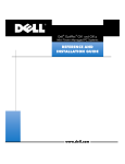
(UJRQRPLF&RPSXWLQJ+DELWV
:$51,1*,PSURSHURUSURORQJHGNH\ERDUGXVHPD\UHVXOWLQLQMXU\
For comfort and efficiency, observe the following ergonomic guidelines when setting
up and using your computer system:
vi
Position your system so that the monitor and keyboard are directly in front of you
as you work. Special shelves are available (from Dell and other sources) to help
you correctly position your keyboard.
Set the monitor at a comfortable viewing distance (usually 510 to 610 millimeters
[20 to 24 inches] from your eyes).
Make sure the monitor screen is at eye level or slightly lower when you are sitting
in front of the monitor.
Adjust the tilt of the monitor, its contrast and brightness settings, and the lighting
around you (such as overhead lights, desk lamps, and the curtains or blinds on
nearby windows) to minimize reflections and glare on the monitor screen.
Use a chair that provides good lower-back support.
Keep your forearms horizontal with your wrists in a neutral, comfortable position
while using the keyboard or mouse.
Always leave space to rest your hands while using the keyboard or mouse.
Let your upper arms hang naturally at your sides.
Sit erect, with your feet resting on the floor and your thighs level.
When sitting, make sure the weight of your legs is on your feet and not on the
front of your chair seat. Adjust your chair’s height or use a footrest, if necessary,
to maintain proper posture.
Vary your work activities. Try to organize your work so that you do not have to
type for extended periods of time. When you stop typing, try to do things that
use both hands.
23186bk0.bk Page vii Thursday, October 29, 1998 11:07 AM
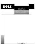
monitor screen at or below eye level
wrists relaxed and flat
monitor and keyboard
positioned directly
in front of user
arms at desk level
feet flat on the floor
:KHQ:RUNLQJ,QVLGH<RXU&RPSXWHU
Before you remove the computer cover, perform the following steps in the sequence
indicated.
&$87,216'RQRWDWWHPSWWRVHUYLFHWKHFRPSXWHUV\VWHP\RXUVHOIH[FHSW
DVH[SODLQHGLQWKLVJXLGHDQGHOVHZKHUHLQ'HOOGRFXPHQWDWLRQ$OZD\V
IROORZLQVWDOODWLRQDQGVHUYLFHLQVWUXFWLRQVFORVHO\
To help avoid possible damage to the system board, wait 10 to 20 seconds after
disconnecting the system from AC power (until the standby LED on the system
board goes out) before removing a component from the system board or disconnecting a peripheral device from the computer.
7XUQRII\RXUFRPSXWHUDQGDQ\SHULSKHUDOV
'LVFRQQHFW\RXUFRPSXWHUDQGSHULSKHUDOVIURPWKHLUSRZHUVRXUFHV
$OVRGLVFRQQHFWDQ\WHOHSKRQHRUWHOHFRPPXQLFDWLRQOLQHVIURPWKH
FRPSXWHU
Doing so reduces the potential for personal injury or shock.
vii
23186bk0.bk Page viii Thursday, October 29, 1998 11:07 AM
7RXFKDQXQSDLQWHGPHWDOVXUIDFHRQWKHFKDVVLVVXFKDVWKHPHWDO
DURXQGWKHFDUGVORWRSHQLQJVDWWKHEDFNRIWKHFRPSXWHUEHIRUH
WRXFKLQJDQ\WKLQJLQVLGH\RXUFRPSXWHU
While you work, periodically touch an unpainted metal surface on the computer
chassis to dissipate any static electricity that might harm internal components.
In addition, take note of these safety guidelines when appropriate:
When you disconnect a cable, pull on its connector or on its strain-relief loop, not
on the cable itself. Some cables have a connector with locking tabs; if you are disconnecting this type of cable, press in on the locking tabs before disconnecting
the cable. As you pull connectors apart, keep them evenly aligned to avoid bending any connector pins. Also, before you connect a cable, make sure both
connectors are correctly oriented and aligned.
Handle components and cards with care. Don’t touch the components or contacts on a card. Hold a card by its edges or by its metal mounting bracket. Hold a
component such as a microprocessor chip by its edges, not by its pins.
:$51,1*
7KHUHLVDGDQJHURIDQHZEDWWHU\H[SORGLQJLILWLVLQFRUUHFWO\LQVWDOOHG
5HSODFHWKHEDWWHU\RQO\ZLWKWKHVDPHRUHTXLYDOHQWW\SHUHFRPPHQGHG
E\WKH PDQXIDFWXUHU'LVFDUGXVHGEDWWHULHVDFFRUGLQJWRWKHPDQXIDF
WXUHU·VLQVWUXFWLRQV
3URWHFWLQJ$JDLQVW(OHFWURVWDWLF'LVFKDUJH
Static electricity can harm delicate components inside your computer. To prevent
static damage, discharge static electricity from your body before you touch any of
your computer’s electronic components, such as the microprocessor. You can do so
by touching an unpainted metal surface on the computer chassis.
As you continue to work inside the computer, periodically touch an unpainted metal
surface to remove any static charge your body may have accumulated.
You can also take the following steps to prevent damage from electrostatic discharge
(ESD):
viii
When unpacking a static-sensitive component from its shipping carton, do not
remove the component from the antistatic packing material until you are ready to
install the component in your computer. Just before unwrapping the antistatic
packaging, be sure to discharge static electricity from your body.
When transporting a sensitive component, first place it in an antistatic container
or packaging.
Handle all sensitive components in a static-safe area. If possible, use antistatic
floor pads and workbench pads.
23186bk0.bk Page ix Thursday, October 29, 1998 11:07 AM
The following caution may appear throughout this document to remind you of these
precautions:
&$87,216HH´3URWHFWLQJ$JDLQVW(OHFWURVWDWLF'LVFKDUJHµLQWKHVDIHW\
LQVWUXFWLRQVDWWKHIURQWRIWKLVJXLGH
ix
23186bk0.bk Page x Thursday, October 29, 1998 11:07 AM
x
23186bk0.bk Page xi Thursday, October 29, 1998 11:07 AM
3UHIDFH
$ERXW7KLV*XLGH
This guide is intended for anyone who uses the Dell Precision WorkStation 410 desktop computer systems. It can be used by both first-time and experienced computer
users who want to learn about the features and operation of the systems or who
want to upgrade their computers. The chapters and appendixes are summarized as
follows:
Everyone should read Chapter 1, “Introduction,” for an overview of the system
features and information on where to get help if you need it.
Everyone should read the first few sections of Chapter 2, “Using the Software
Support Utilities,” to find out which utilities and drivers have been included with
the system. Only users who want to use one of the utilities or drivers need to
read the rest of Chapter 2.
Everyone should read the first several sections of Chapter 3, “Using the System
Setup Program,” to familiarize themselves with this important program. Only
users who want to make configuration changes to their system or who want to
use the password features need to read the rest of Chapter 3.
Users who add or remove an Industry-Standard Architecture (ISA) expansion card
should read Chapter 4, “Using the ISA Configuration Utility.”
Users who want to connect their system to a network should read Chapter 5,
“Using the Network Interface Controller.” This chapter provides information on
connecting the system to a network, configuring the optional network interface
controller (NIC), and installing drivers for the NIC.
Users who need information on the integrated sound features of the computer system should read Chapter 6, “Using the Integrated Audio Controller.” Chapter 6
provides information on connecting audio equipment to your computer, installing
audio drivers, and reconfiguring the integrated audio controller.
Chapter 7, “Using the Integrated SCSI Controllers,” describes the system’s small
computer system interface (SCSI) controllers and provides information on how to
install SCSI drivers.
Chapter 8, “Working Inside Your Computer,” Chapter 9, “Installing System Board
Options,” and Chapter 10, “Installing Drives,” are intended for users who want
to install or remove options inside the computer, such as dual in-line memory
modules (DIMMs), expansion cards, or drives.
xi
23186bk0.bk Page xii Thursday, October 29, 1998 11:07 AM
Appendix A, “Technical Specifications,” and Appendix B, “Hardware Configuration Features,” are intended primarily as reference material for users interested
in learning more about the details of the system. Users who add internal options
may need to refer to Appendix B to change jumper or switch settings.
Appendix C, “ISA Configuration Utility Messages,” describes error messages
generated by the ISA Configuration Utility (ICU), possible causes, and corrective
actions.
Appendix D, “Maintaining the System,” describes preventive maintenance procedures that you should perform regularly to keep your computer system in top
operating condition.
Appendix E, “Regulatory Notices,” is for users who are interested in which regulatory agencies have tested and approved the Dell Precision WorkStation 410
desktop systems.
Appendix F, “Warranties and Return Policy,” describes the warranty for your Dell
system and the “Total Satisfaction” Return Policy.
The Glossary provides definitions of terms, acronyms, and abbreviations used in
this guide.
:DUUDQW\DQG5HWXUQ3ROLF\,QIRUPDWLRQ
Dell Computer Corporation (“Dell”) manufactures its hardware products from parts
and components that are new or equivalent to new in accordance with industrystandard practices. For information about the Dell warranty for your system, see
Appendix F, “Warranties and Return Policy.”
2WKHU'RFXPHQWV<RX0D\1HHG
Besides this User’s Guide, the following documentation is included with your system:
The Getting Started sheet provides step-by-step instructions for setting up your
computer system.
The Diagnostics and Troubleshooting Guide includes troubleshooting procedures
and instructions for using the Dell Diagnostics to test your computer system.
Video card documentation from the card manufacturer describes the video card
and video drivers included with the system. Refer to this documentation for information about configuring and optimizing your video subsystem.
You may also have one or more of the following documents.
NOTE: Documentation updates are sometimes included with your system to describe
changes to your system or software. Always read these updates before consulting
any other documentation because the updates often contain the latest information.
xii
Operating system documentation is included if you ordered your operating
system software from Dell. This documentation describes how to install (if necessary), configure, and use your operating system software.
23186bk0.bk Page xiii Thursday, October 29, 1998 11:07 AM
Documentation is included with any options you purchase separately from your
system. This documentation includes information that you need to configure and
install these options in your Dell computer. Installation instructions for the
options are included in this User’s Guide or in the documentation that came with
the options.
Technical information files—sometimes called “readme” files—may be installed
on your hard-disk drive to provide last-minute updates about technical changes to
your system or advanced technical reference material intended for experienced
users or technicians.
1RWDWLRQDO&RQYHQWLRQV
The following subsections describe notational conventions used in this document.
:DUQLQJV&DXWLRQVDQG1RWHV
Throughout this guide, there may be blocks of text printed in bold or italic type. These
blocks are warnings, cautions, and notes, and they are used as follows:
:$51,1*$:$51,1*LQGLFDWHVWKHSRWHQWLDOIRUERGLO\KDUPDQGWHOOV
\RXKRZWRDYRLGWKHSUREOHP
&$87,21$&$87,21LQGLFDWHVHLWKHUSRWHQWLDOGDPDJHWRKDUGZDUHRU
ORVVRIGDWDDQGWHOOV\RXKRZWRDYRLGWKHSUREOHP
NOTE: A NOTE indicates important information that helps you make better use of
your computer system.
7\SRJUDSKLFDO&RQYHQWLRQV
The following list defines (where appropriate) and illustrates typographical conventions used as visual cues for specific elements of text throughout this document:
Keycaps, the labeling that appears on the keys on a keyboard, are enclosed in
angle brackets.
Example: <Enter>
Key combinations are series of keys to be pressed simultaneously (unless otherwise indicated) to perform a single function.
Example: <Ctrl><Alt><Enter>
Commands presented in lowercase bold are for reference purposes only and are
not intended to be typed when referenced.
Example: “Use the format command to . . . .”
In contrast, commands presented in the Courier New font are part of an instruction and intended to be typed.
Example: “Type IRUPDWD to format the diskette in drive A.”
xiii
23186bk0.bk Page xiv Thursday, October 29, 1998 11:07 AM
Filenames and directory names are presented in lowercase bold.
Examples: autoexec.bat and c:\windows
Syntax lines consist of a command and all its possible parameters. Commands
are displayed in lowercase bold; variable parameters (those for which you substitute a value) are displayed in lowercase italics; constant parameters are
displayed in lowercase bold. The brackets indicate items that are optional.
Example: del [drive:] [path] filename [/p]
Command lines consist of a command and may include one or more of the command’s possible parameters. Command lines are presented in the Courier New
font.
Example: GHOF?P\ILOHGRF
Screen text is text that appears on the screen of your monitor or display. It can be
a system message, for example, or it can be text that you are instructed to type
as part of a command (referred to as a command line). Screen text is presented
in the Courier New font.
Example: The following message appears on your screen:
1RERRWGHYLFHDYDLODEOH
Example: “Type PGF?GRV and press <Enter>.”
Variables are placeholders for which you substitute a value. They are presented in
italics.
Example: DIMMx (where x represents the DIMM socket designation)
xiv
23186bk0.bk Page xv Thursday, October 29, 1998 11:07 AM
&RQWHQWV
&KDSWHU
,QWURGXFWLRQ System Features . . . . . . . . . . . . . . . . . . . . . . . . . . . . . . . . . . . . . . . . . . . . . . . . . . . 1-1
Important Note to Windows 95 and Windows NT 4.0 Users . . . . . . . . . . . . . . . . . 1-6
Reinstalling Windows NT 4.0 . . . . . . . . . . . . . . . . . . . . . . . . . . . . . . . . . . . . . . 1-6
Reinstalling Windows 95 . . . . . . . . . . . . . . . . . . . . . . . . . . . . . . . . . . . . . . . . . 1-7
Intel PIIX4 INF Update Installer for Windows 95 . . . . . . . . . . . . . . . . . . . 1-8
Front Panel . . . . . . . . . . . . . . . . . . . . . . . . . . . . . . . . . . . . . . . . . . . . . . . . . . . . . . . 1-9
Back Panel . . . . . . . . . . . . . . . . . . . . . . . . . . . . . . . . . . . . . . . . . . . . . . . . . . . . . . . 1-10
Connecting External Devices . . . . . . . . . . . . . . . . . . . . . . . . . . . . . . . . . . . . . 1-10
Security Cable Slot and Padlock Ring. . . . . . . . . . . . . . . . . . . . . . . . . . . . . . . 1-10
Getting Help . . . . . . . . . . . . . . . . . . . . . . . . . . . . . . . . . . . . . . . . . . . . . . . . . . . . . 1-11
&KDSWHU
8VLQJWKH6RIWZDUH6XSSRUW8WLOLWLHV Dell-Installed Software Support Utilities . . . . . . . . . . . . . . . . . . . . . . . . . . . . . . . .
Backing Up the Software Support Utilities . . . . . . . . . . . . . . . . . . . . . . . . . . . . . . .
Software Support Utilities on Diskette . . . . . . . . . . . . . . . . . . . . . . . . . . . . . . . . . .
System Utilities and Services . . . . . . . . . . . . . . . . . . . . . . . . . . . . . . . . . . . . . . . . .
Reinstalling the Dell System Utilities and Services for Windows 95 . . . . . . . .
Reinstalling the Dell System Utilities and Services for Windows NT 4.0. . . . .
Removing a Service . . . . . . . . . . . . . . . . . . . . . . . . . . . . . . . . . . . . . . . . . . . . .
Asset Tag Utility . . . . . . . . . . . . . . . . . . . . . . . . . . . . . . . . . . . . . . . . . . . . . . . .
Assigning and Deleting an Asset Tag Number . . . . . . . . . . . . . . . . . . . . .
Assigning and Deleting an Owner Tag . . . . . . . . . . . . . . . . . . . . . . . . . . .
Dell AutoShutdown Service . . . . . . . . . . . . . . . . . . . . . . . . . . . . . . . . . . . . . .
How AutoShutdown Works . . . . . . . . . . . . . . . . . . . . . . . . . . . . . . . . . . .
If Your Operating System Locks Up . . . . . . . . . . . . . . . . . . . . . . . . . . . . .
Dell ThermalShutdown Service . . . . . . . . . . . . . . . . . . . . . . . . . . . . . . . . . . . .
Auto Power On Utility . . . . . . . . . . . . . . . . . . . . . . . . . . . . . . . . . . . . . . . . . . .
Installing the Auto Power On Utility . . . . . . . . . . . . . . . . . . . . . . . . . . . . .
2-2
2-2
2-2
2-2
2-3
2-3
2-4
2-4
2-5
2-5
2-5
2-6
2-6
2-6
2-7
2-7
xv
23186bk0.bk Page xvi Thursday, October 29, 1998 11:07 AM
Bus-Mastering EIDE Drivers . . . . . . . . . . . . . . . . . . . . . . . . . . . . . . . . . . . . . . . . . 2-8
Reinstalling the Windows NT 4.0 Bus-Mastering EIDE Driver. . . . . . . . . . . . . 2-8
Removing the Windows NT 4.0 Bus-Mastering EIDE Driver. . . . . . . . . . . . . . 2-9
Enabling the Windows 95 Bus-Mastering EIDE Driver . . . . . . . . . . . . . . . . . 2-10
&KDSWHU
8VLQJWKH6\VWHP6HWXS3URJUDP Entering the System Setup Program . . . . . . . . . . . . . . . . . . . . . . . . . . . . . . . . . . . 3-2
System Setup Screens . . . . . . . . . . . . . . . . . . . . . . . . . . . . . . . . . . . . . . . . . . . . . . 3-2
Using the System Setup Program. . . . . . . . . . . . . . . . . . . . . . . . . . . . . . . . . . . . . . 3-4
System Setup Options . . . . . . . . . . . . . . . . . . . . . . . . . . . . . . . . . . . . . . . . . . . . . . 3-6
Time . . . . . . . . . . . . . . . . . . . . . . . . . . . . . . . . . . . . . . . . . . . . . . . . . . . . . . . . . 3-6
Date . . . . . . . . . . . . . . . . . . . . . . . . . . . . . . . . . . . . . . . . . . . . . . . . . . . . . . . . . 3-6
Diskette Drive A and Diskette Drive B. . . . . . . . . . . . . . . . . . . . . . . . . . . . . . . 3-6
Drives: Primary and Secondary . . . . . . . . . . . . . . . . . . . . . . . . . . . . . . . . . . . . 3-7
EIDE Devices Other Than Hard-Disk Drives . . . . . . . . . . . . . . . . . . . . . . . 3-7
EIDE Hard-Disk Drives . . . . . . . . . . . . . . . . . . . . . . . . . . . . . . . . . . . . . . . 3-7
If You Have a Problem . . . . . . . . . . . . . . . . . . . . . . . . . . . . . . . . . . . . . . . 3-8
Reserved Memory . . . . . . . . . . . . . . . . . . . . . . . . . . . . . . . . . . . . . . . . . . . . . 3-9
CPU Speed. . . . . . . . . . . . . . . . . . . . . . . . . . . . . . . . . . . . . . . . . . . . . . . . . . . . 3-9
Num Lock . . . . . . . . . . . . . . . . . . . . . . . . . . . . . . . . . . . . . . . . . . . . . . . . . . . . 3-9
ACPI . . . . . . . . . . . . . . . . . . . . . . . . . . . . . . . . . . . . . . . . . . . . . . . . . . . . . . . . . 3-9
Chassis Intrusion . . . . . . . . . . . . . . . . . . . . . . . . . . . . . . . . . . . . . . . . . . . . . . 3-10
Thermal Power-Off . . . . . . . . . . . . . . . . . . . . . . . . . . . . . . . . . . . . . . . . . . . . 3-10
Video DAC Snoop . . . . . . . . . . . . . . . . . . . . . . . . . . . . . . . . . . . . . . . . . . . . . 3-10
Keyboard Errors . . . . . . . . . . . . . . . . . . . . . . . . . . . . . . . . . . . . . . . . . . . . . . 3-10
System Password . . . . . . . . . . . . . . . . . . . . . . . . . . . . . . . . . . . . . . . . . . . . . 3-11
Password Status . . . . . . . . . . . . . . . . . . . . . . . . . . . . . . . . . . . . . . . . . . . . . . 3-11
Using Password Status With a System Password Enabled . . . . . . . . . . 3-11
Using Password Status Without a System Password Enabled . . . . . . . 3-12
Boot Sequence . . . . . . . . . . . . . . . . . . . . . . . . . . . . . . . . . . . . . . . . . . . . . . . 3-12
Diskette First . . . . . . . . . . . . . . . . . . . . . . . . . . . . . . . . . . . . . . . . . . . . . 3-12
Hard Disk Only . . . . . . . . . . . . . . . . . . . . . . . . . . . . . . . . . . . . . . . . . . . . 3-12
CD-ROM First . . . . . . . . . . . . . . . . . . . . . . . . . . . . . . . . . . . . . . . . . . . . . 3-12
Device List . . . . . . . . . . . . . . . . . . . . . . . . . . . . . . . . . . . . . . . . . . . . . . . 3-12
Setup Password . . . . . . . . . . . . . . . . . . . . . . . . . . . . . . . . . . . . . . . . . . . . . 3-14
Auto Power On . . . . . . . . . . . . . . . . . . . . . . . . . . . . . . . . . . . . . . . . . . . . . . . 3-14
Power Management . . . . . . . . . . . . . . . . . . . . . . . . . . . . . . . . . . . . . . . . . . 3-15
Saving Monitor Power . . . . . . . . . . . . . . . . . . . . . . . . . . . . . . . . . . . . . . 3-15
Saving EIDE Hard-Disk Drive Power. . . . . . . . . . . . . . . . . . . . . . . . . . . . 3-16
Wakeup On LAN . . . . . . . . . . . . . . . . . . . . . . . . . . . . . . . . . . . . . . . . . . . . . . 3-16
Sound. . . . . . . . . . . . . . . . . . . . . . . . . . . . . . . . . . . . . . . . . . . . . . . . . . . . . . . 3-17
NIC . . . . . . . . . . . . . . . . . . . . . . . . . . . . . . . . . . . . . . . . . . . . . . . . . . . . . . . . 3-17
xvi
23186bk0.bk Page xvii Thursday, October 29, 1998 11:07 AM
Mouse . . . . . . . . . . . . . . . . . . . . . . . . . . . . . . . . . . . . . . . . . . . . . . . . . . . . . . 3-17
Serial Port 1 and Serial Port 2 . . . . . . . . . . . . . . . . . . . . . . . . . . . . . . . . . . . . 3-17
Parallel Port . . . . . . . . . . . . . . . . . . . . . . . . . . . . . . . . . . . . . . . . . . . . . . . . . 3-18
Parallel Mode . . . . . . . . . . . . . . . . . . . . . . . . . . . . . . . . . . . . . . . . . . . . . . . . . 3-18
IDE Hard Disk . . . . . . . . . . . . . . . . . . . . . . . . . . . . . . . . . . . . . . . . . . . . . . . . 3-18
Diskette . . . . . . . . . . . . . . . . . . . . . . . . . . . . . . . . . . . . . . . . . . . . . . . . . . . . . 3-18
Speaker . . . . . . . . . . . . . . . . . . . . . . . . . . . . . . . . . . . . . . . . . . . . . . . . . . . . . 3-19
SCSI . . . . . . . . . . . . . . . . . . . . . . . . . . . . . . . . . . . . . . . . . . . . . . . . . . . . . . . . 3-19
System Data. . . . . . . . . . . . . . . . . . . . . . . . . . . . . . . . . . . . . . . . . . . . . . . . . . 3-19
Using the System Password Feature . . . . . . . . . . . . . . . . . . . . . . . . . . . . . . . . . . 3-20
Assigning a System Password . . . . . . . . . . . . . . . . . . . . . . . . . . . . . . . . . . . . 3-20
Using Your System Password to Secure Your System . . . . . . . . . . . . . . . . . 3-22
Deleting or Changing an Existing System Password . . . . . . . . . . . . . . . . . . 3-23
Using the Setup Password Feature. . . . . . . . . . . . . . . . . . . . . . . . . . . . . . . . . . . . 3-23
Assigning a Setup Password . . . . . . . . . . . . . . . . . . . . . . . . . . . . . . . . . . . . . 3-24
Operating With a Setup Password Enabled . . . . . . . . . . . . . . . . . . . . . . . . . . 3-24
Deleting or Changing an Existing Setup Password . . . . . . . . . . . . . . . . . . . . 3-24
Disabling a Forgotten Password . . . . . . . . . . . . . . . . . . . . . . . . . . . . . . . . . . . . . . 3-25
Responding to Error Messages . . . . . . . . . . . . . . . . . . . . . . . . . . . . . . . . . . . . . . 3-26
&KDSWHU
8VLQJWKH,6$&RQILJXUDWLRQ8WLOLW\ Quick Start . . . . . . . . . . . . . . . . . . . . . . . . . . . . . . . . . . . . . . . . . . . . . . . . . . . . . . . 4-2
About the ICU . . . . . . . . . . . . . . . . . . . . . . . . . . . . . . . . . . . . . . . . . . . . . . . . . . . . . 4-3
ICU Database . . . . . . . . . . . . . . . . . . . . . . . . . . . . . . . . . . . . . . . . . . . . . . . . . . 4-3
When to Run the ICU . . . . . . . . . . . . . . . . . . . . . . . . . . . . . . . . . . . . . . . . . . . . . . . 4-3
Preparing to Use the ICU. . . . . . . . . . . . . . . . . . . . . . . . . . . . . . . . . . . . . . . . . . . . . 4-4
Backing Up the ICU Diskette . . . . . . . . . . . . . . . . . . . . . . . . . . . . . . . . . . . . . . 4-4
Starting the ICU . . . . . . . . . . . . . . . . . . . . . . . . . . . . . . . . . . . . . . . . . . . . . . . . . . . . 4-5
Accessing Help. . . . . . . . . . . . . . . . . . . . . . . . . . . . . . . . . . . . . . . . . . . . . . . . . 4-5
Making Selections in the ICU . . . . . . . . . . . . . . . . . . . . . . . . . . . . . . . . . . . . . . 4-5
Adding a Listed Card . . . . . . . . . . . . . . . . . . . . . . . . . . . . . . . . . . . . . . . . . . . . . . . . 4-6
Adding an Unlisted Card . . . . . . . . . . . . . . . . . . . . . . . . . . . . . . . . . . . . . . . . . . . . . 4-9
Modifying a Card . . . . . . . . . . . . . . . . . . . . . . . . . . . . . . . . . . . . . . . . . . . . . . . . . . 4-11
Removing a Card . . . . . . . . . . . . . . . . . . . . . . . . . . . . . . . . . . . . . . . . . . . . . . . . . . 4-13
Viewing Resources . . . . . . . . . . . . . . . . . . . . . . . . . . . . . . . . . . . . . . . . . . . . . . . . 4-13
Saving the System Configuration . . . . . . . . . . . . . . . . . . . . . . . . . . . . . . . . . . . . . 4-14
Exiting the ICU. . . . . . . . . . . . . . . . . . . . . . . . . . . . . . . . . . . . . . . . . . . . . . . . . . . . 4-14
Locking and Unlocking Cards . . . . . . . . . . . . . . . . . . . . . . . . . . . . . . . . . . . . . . . . 4-15
Locking and Unlocking All Resources . . . . . . . . . . . . . . . . . . . . . . . . . . . . . . 4-15
Locking and Unlocking Configuration Resources . . . . . . . . . . . . . . . . . . . . . . 4-16
xvii
23186bk0.bk Page xviii Thursday, October 29, 1998 11:07 AM
&KDSWHU
8VLQJWKH1HWZRUN,QWHUIDFH&RQWUROOHU Connecting to a Network . . . . . . . . . . . . . . . . . . . . . . . . . . . . . . . . . . . . . . . . . . .
Network Cable Requirements . . . . . . . . . . . . . . . . . . . . . . . . . . . . . . . . . . . . .
Setting the Network Frame Type. . . . . . . . . . . . . . . . . . . . . . . . . . . . . . . . . . .
Configuring the NIC . . . . . . . . . . . . . . . . . . . . . . . . . . . . . . . . . . . . . . . . . . . . . . . .
Windows NT 4.0 NIC Driver . . . . . . . . . . . . . . . . . . . . . . . . . . . . . . . . . . . . . .
Windows 95 NIC Driver . . . . . . . . . . . . . . . . . . . . . . . . . . . . . . . . . . . . . . . . .
Dell-Installed Windows 95 Service Release 2.1 . . . . . . . . . . . . . . . . . . . .
Windows 95 Operating Systems Not Installed by Dell. . . . . . . . . . . . . . .
Using the NDIS 2.01 Driver With Windows 95. . . . . . . . . . . . . . . . . . . . .
Using 3Com EtherDisk XL Version 3.01 Diskettes . . . . . . . . . . . . . . . . . .
&KDSWHU
8VLQJWKH,QWHJUDWHG$XGLR&RQWUROOHU Connecting Audio Devices . . . . . . . . . . . . . . . . . . . . . . . . . . . . . . . . . . . . . . . . . . .
Speakers . . . . . . . . . . . . . . . . . . . . . . . . . . . . . . . . . . . . . . . . . . . . . . . . . . . . .
Microphones . . . . . . . . . . . . . . . . . . . . . . . . . . . . . . . . . . . . . . . . . . . . . . . . . .
Record/Playback Devices. . . . . . . . . . . . . . . . . . . . . . . . . . . . . . . . . . . . . . . . .
CD-ROM Drives . . . . . . . . . . . . . . . . . . . . . . . . . . . . . . . . . . . . . . . . . . . . . . . .
Adjusting Volume . . . . . . . . . . . . . . . . . . . . . . . . . . . . . . . . . . . . . . . . . . . . . . . . . .
Adjusting Volume in Windows 95 . . . . . . . . . . . . . . . . . . . . . . . . . . . . . . . . . .
Adjusting Volume in Windows NT 4.0 . . . . . . . . . . . . . . . . . . . . . . . . . . . . . . .
Muting the Internal Speaker . . . . . . . . . . . . . . . . . . . . . . . . . . . . . . . . . . . . . .
Adjusting 3D Sound . . . . . . . . . . . . . . . . . . . . . . . . . . . . . . . . . . . . . . . . . . . . . . . .
Using Audio Utilities . . . . . . . . . . . . . . . . . . . . . . . . . . . . . . . . . . . . . . . . . . . . . . . .
Installing Audio Drivers . . . . . . . . . . . . . . . . . . . . . . . . . . . . . . . . . . . . . . . . . . . . . .
Audio Drivers for Windows 95. . . . . . . . . . . . . . . . . . . . . . . . . . . . . . . . . . . . .
Audio Drivers for Windows NT 4.0 . . . . . . . . . . . . . . . . . . . . . . . . . . . . . . . . .
&KDSWHU
6-1
6-2
6-2
6-2
6-2
6-3
6-3
6-3
6-4
6-4
6-4
6-5
6-5
6-6
8VLQJWKH,QWHJUDWHG6&6,&RQWUROOHUV SCSI Device Considerations . . . . . . . . . . . . . . . . . . . . . . . . . . . . . . . . . . . . . . . . . .
Installing SCSI Drivers. . . . . . . . . . . . . . . . . . . . . . . . . . . . . . . . . . . . . . . . . . . . . . .
Installing SCSI Drivers for Windows 95 . . . . . . . . . . . . . . . . . . . . . . . . . . . . . .
SCSI Driver for the Primary SCSI Controller . . . . . . . . . . . . . . . . . . . . . . .
SCSI Driver for the Secondary SCSI Controller. . . . . . . . . . . . . . . . . . . . .
Installing SCSI Drivers After Installing Windows NT 4.0 . . . . . . . . . . . . . . . . .
Installing SCSI Drivers During Windows NT 4.0 Installation . . . . . . . . . . . . . .
&KDSWHU
5-2
5-3
5-3
5-4
5-4
5-5
5-5
5-7
5-9
5-9
7-2
7-2
7-2
7-3
7-3
7-4
7-5
:RUNLQJ,QVLGH<RXU&RPSXWHU Before You Begin . . . . . . . . . . . . . . . . . . . . . . . . . . . . . . . . . . . . . . . . . . . . . . . . . . 8-1
Safety First—For You and Your Computer. . . . . . . . . . . . . . . . . . . . . . . . . . . . 8-1
Unpacking Your Hardware Option . . . . . . . . . . . . . . . . . . . . . . . . . . . . . . . . . . 8-2
xviii
23186bk0.bk Page xix Thursday, October 29, 1998 11:07 AM
Removing the Computer Cover. . . . . . . . . . . . . . . . . . . . . . . . . . . . . . . . . . . . . . . .
Replacing the Computer Cover . . . . . . . . . . . . . . . . . . . . . . . . . . . . . . . . . . . . . . . .
Inside Your Computer . . . . . . . . . . . . . . . . . . . . . . . . . . . . . . . . . . . . . . . . . . . . . . .
Rotating the Power Supply Away From the System Board. . . . . . . . . . . . . . . . . . .
&KDSWHU
8-2
8-4
8-5
8-7
,QVWDOOLQJ6\VWHP%RDUG2SWLRQV Expansion Cards . . . . . . . . . . . . . . . . . . . . . . . . . . . . . . . . . . . . . . . . . . . . . . . . . . . 9-2
Expansion Slots . . . . . . . . . . . . . . . . . . . . . . . . . . . . . . . . . . . . . . . . . . . . . . . . 9-3
Installing an Expansion Card. . . . . . . . . . . . . . . . . . . . . . . . . . . . . . . . . . . . . . . 9-4
Removing an Expansion Card . . . . . . . . . . . . . . . . . . . . . . . . . . . . . . . . . . . . . 9-6
Adding Memory. . . . . . . . . . . . . . . . . . . . . . . . . . . . . . . . . . . . . . . . . . . . . . . . . . . . 9-6
DIMM Installation Guidelines . . . . . . . . . . . . . . . . . . . . . . . . . . . . . . . . . . . . . . 9-7
Installing a DIMM . . . . . . . . . . . . . . . . . . . . . . . . . . . . . . . . . . . . . . . . . . . 9-9
Removing a DIMM . . . . . . . . . . . . . . . . . . . . . . . . . . . . . . . . . . . . . . . . . 9-10
Microprocessor Upgrades . . . . . . . . . . . . . . . . . . . . . . . . . . . . . . . . . . . . . . . . . . . 9-10
Adding or Replacing a Microprocessor. . . . . . . . . . . . . . . . . . . . . . . . . . . . . . 9-11
Replacing the System Battery . . . . . . . . . . . . . . . . . . . . . . . . . . . . . . . . . . . . . . . . 9-14
&KDSWHU
,QVWDOOLQJ'ULYHV Removing and Replacing Front-Panel Inserts . . . . . . . . . . . . . . . . . . . . . . . . . . . . 10-2
Connecting Drives . . . . . . . . . . . . . . . . . . . . . . . . . . . . . . . . . . . . . . . . . . . . . . . . 10-3
Installing a Drive in a 5.25-Inch Drive Bay . . . . . . . . . . . . . . . . . . . . . . . . . . . . . . . 10-5
Installing an EIDE Hard-Disk Drive. . . . . . . . . . . . . . . . . . . . . . . . . . . . . . . . . . . . . 10-9
EIDE Drive Addressing . . . . . . . . . . . . . . . . . . . . . . . . . . . . . . . . . . . . . . . . . 10-10
Installing an EIDE Hard-Disk Drive in the Hard-Disk Drive Bracket . . . . . . . 10-10
Partitioning and Logically Formatting Your EIDE Hard-Disk Drive . . . . . . . . 10-15
Installing SCSI Devices . . . . . . . . . . . . . . . . . . . . . . . . . . . . . . . . . . . . . . . . . . . . 10-15
SCSI Configuration Guidelines . . . . . . . . . . . . . . . . . . . . . . . . . . . . . . . . . . . 10-15
SCSI ID Numbers . . . . . . . . . . . . . . . . . . . . . . . . . . . . . . . . . . . . . . . . . 10-15
Device Termination . . . . . . . . . . . . . . . . . . . . . . . . . . . . . . . . . . . . . . 10-16
SCSI Cables . . . . . . . . . . . . . . . . . . . . . . . . . . . . . . . . . . . . . . . . . . . . . . . . . 10-17
General Procedure for Installing SCSI Devices . . . . . . . . . . . . . . . . . . . . . . 10-17
Partitioning and Formatting SCSI Hard-Disk Drives . . . . . . . . . . . . . . . . . . . 10-20
$SSHQGL[$
7HFKQLFDO6SHFLILFDWLRQV $
$SSHQGL[%
+DUGZDUH&RQILJXUDWLRQ)HDWXUHV %
Jumpers and Switches—A General Explanation . . . . . . . . . . . . . . . . . . . . . . . . . . . B-1
Jumpers . . . . . . . . . . . . . . . . . . . . . . . . . . . . . . . . . . . . . . . . . . . . . . . . . . . . . . B-1
Switches. . . . . . . . . . . . . . . . . . . . . . . . . . . . . . . . . . . . . . . . . . . . . . . . . . . . . . B-2
System Board Labels. . . . . . . . . . . . . . . . . . . . . . . . . . . . . . . . . . . . . . . . . . . . . . . . B-5
xix
23186bk0.bk Page xx Thursday, October 29, 1998 11:07 AM
I/O Ports and Connectors . . . . . . . . . . . . . . . . . . . . . . . . . . . . . . . . . . . . . . . . . . . . B-6
Serial and Parallel Ports . . . . . . . . . . . . . . . . . . . . . . . . . . . . . . . . . . . . . . . . . . B-7
Adding an Expansion Card Containing Serial or Parallel Ports . . . . . . . . . B-7
Serial Port Connectors . . . . . . . . . . . . . . . . . . . . . . . . . . . . . . . . . . . . . . . B-8
Parallel Port Connector . . . . . . . . . . . . . . . . . . . . . . . . . . . . . . . . . . . . . . . B-9
External SCSI Connector . . . . . . . . . . . . . . . . . . . . . . . . . . . . . . . . . . . . . . . . B-10
Keyboard and Mouse Connectors . . . . . . . . . . . . . . . . . . . . . . . . . . . . . . . . . B-12
Keyboard Connector . . . . . . . . . . . . . . . . . . . . . . . . . . . . . . . . . . . . . . . . B-12
Mouse Connector . . . . . . . . . . . . . . . . . . . . . . . . . . . . . . . . . . . . . . . . . . B-13
Video Connector . . . . . . . . . . . . . . . . . . . . . . . . . . . . . . . . . . . . . . . . . . . . . . B-14
NIC Connector . . . . . . . . . . . . . . . . . . . . . . . . . . . . . . . . . . . . . . . . . . . . . . . . B-14
USB Connectors . . . . . . . . . . . . . . . . . . . . . . . . . . . . . . . . . . . . . . . . . . . . . . B-15
Microphone Jack . . . . . . . . . . . . . . . . . . . . . . . . . . . . . . . . . . . . . . . . . . . . . B-15
Line-Out Jack . . . . . . . . . . . . . . . . . . . . . . . . . . . . . . . . . . . . . . . . . . . . . . . . . B-16
Line-In Jack . . . . . . . . . . . . . . . . . . . . . . . . . . . . . . . . . . . . . . . . . . . . . . . . . . B-16
Interrupt Assignments . . . . . . . . . . . . . . . . . . . . . . . . . . . . . . . . . . . . . . . . . . . . . B-16
Memory Allocations . . . . . . . . . . . . . . . . . . . . . . . . . . . . . . . . . . . . . . . . . . . . . . . B-17
$SSHQGL[&
,6$&RQILJXUDWLRQ8WLOLW\0HVVDJHV &
ICU Error Messages . . . . . . . . . . . . . . . . . . . . . . . . . . . . . . . . . . . . . . . . . . . . . . . . C-1
Configuration Manager Messages . . . . . . . . . . . . . . . . . . . . . . . . . . . . . . . . . . . . . C-7
$SSHQGL['
0DLQWDLQLQJWKH6\VWHP '
Data Preservation . . . . . . . . . . . . . . . . . . . . . . . . . . . . . . . . . . . . . . . . . . . . . . . . . . D-1
Scheduling Backups. . . . . . . . . . . . . . . . . . . . . . . . . . . . . . . . . . . . . . . . . . . . . D-1
Backup Devices . . . . . . . . . . . . . . . . . . . . . . . . . . . . . . . . . . . . . . . . . . . . . . . . D-1
Recovering Data. . . . . . . . . . . . . . . . . . . . . . . . . . . . . . . . . . . . . . . . . . . . . . . . D-2
Cleaning System Components . . . . . . . . . . . . . . . . . . . . . . . . . . . . . . . . . . . . . . . . D-2
Recommended Tools and Accessories . . . . . . . . . . . . . . . . . . . . . . . . . . . . . . D-3
Cleaning the Computer, Monitor, and Keyboard Exteriors . . . . . . . . . . . . . . . D-3
Cleaning Drives
. . . . . . . . . . . . . . . . . . . . . . . . . . . . . . . . . . . . . . . . . . . . . . D-4
Environmental Factors . . . . . . . . . . . . . . . . . . . . . . . . . . . . . . . . . . . . . . . . . . . . . . D-4
Temperature . . . . . . . . . . . . . . . . . . . . . . . . . . . . . . . . . . . . . . . . . . . . . . . . . . D-4
Humidity. . . . . . . . . . . . . . . . . . . . . . . . . . . . . . . . . . . . . . . . . . . . . . . . . . . . . . D-5
Altitude. . . . . . . . . . . . . . . . . . . . . . . . . . . . . . . . . . . . . . . . . . . . . . . . . . . . . . . D-5
Dust and Particles . . . . . . . . . . . . . . . . . . . . . . . . . . . . . . . . . . . . . . . . . . . . . . D-5
Corrosion . . . . . . . . . . . . . . . . . . . . . . . . . . . . . . . . . . . . . . . . . . . . . . . . . . . . . D-6
ESD . . . . . . . . . . . . . . . . . . . . . . . . . . . . . . . . . . . . . . . . . . . . . . . . . . . . . . . . . D-6
Electromagnetic and Radio Frequency Interference . . . . . . . . . . . . . . . . . . . . D-6
Magnetism. . . . . . . . . . . . . . . . . . . . . . . . . . . . . . . . . . . . . . . . . . . . . . . . . . . . D-7
Shock and Vibration . . . . . . . . . . . . . . . . . . . . . . . . . . . . . . . . . . . . . . . . . . . . . D-7
Power Source Interruptions . . . . . . . . . . . . . . . . . . . . . . . . . . . . . . . . . . . . . . . D-8
xx
23186bk0.bk Page xxi Thursday, October 29, 1998 11:07 AM
Power Protection Devices . . . . . . . . . . . . . . . . . . . . . . . . . . . . . . . . . . . . . . . . . . . . D-9
Surge Protectors . . . . . . . . . . . . . . . . . . . . . . . . . . . . . . . . . . . . . . . . . . . . . . . D-9
Line Conditioners . . . . . . . . . . . . . . . . . . . . . . . . . . . . . . . . . . . . . . . . . . . . . . . D-9
Uninterruptible Power Supplies . . . . . . . . . . . . . . . . . . . . . . . . . . . . . . . . . . . . D-9
$SSHQGL[(
5HJXODWRU\1RWLFHV(
FCC Notices (U.S. Only) . . . . . . . . . . . . . . . . . . . . . . . . . . . . . . . . . . . . . . . . . . . . . E-1
Class A . . . . . . . . . . . . . . . . . . . . . . . . . . . . . . . . . . . . . . . . . . . . . . . . . . . . . . . E-1
Class B . . . . . . . . . . . . . . . . . . . . . . . . . . . . . . . . . . . . . . . . . . . . . . . . . . . . . . . E-2
IC Notice (Canada Only). . . . . . . . . . . . . . . . . . . . . . . . . . . . . . . . . . . . . . . . . . . . . . E-3
EN 55022 Compliance (Czech Republic Only) . . . . . . . . . . . . . . . . . . . . . . . . . . . . . E-3
CE Notice. . . . . . . . . . . . . . . . . . . . . . . . . . . . . . . . . . . . . . . . . . . . . . . . . . . . . . . . . E-4
VCCI Notices (Japan Only). . . . . . . . . . . . . . . . . . . . . . . . . . . . . . . . . . . . . . . . . . . . E-4
Class A ITE . . . . . . . . . . . . . . . . . . . . . . . . . . . . . . . . . . . . . . . . . . . . . . . . . . . . E-5
Class B ITE . . . . . . . . . . . . . . . . . . . . . . . . . . . . . . . . . . . . . . . . . . . . . . . . . . . . E-5
Korean Regulatory Notice . . . . . . . . . . . . . . . . . . . . . . . . . . . . . . . . . . . . . . . . . . . . E-5
Class A Device . . . . . . . . . . . . . . . . . . . . . . . . . . . . . . . . . . . . . . . . . . . . . . . . . E-5
Class B Device . . . . . . . . . . . . . . . . . . . . . . . . . . . . . . . . . . . . . . . . . . . . . . . . . E-5
Polish Center for Testing and Certification Notice. . . . . . . . . . . . . . . . . . . . . . . . . . E-6
8ZNBHBOJB1PMTLJFHP$FOUSVN#BEBËJ$FSUZGJLBDKJ . . . . . . . . . . . . . . . . . . . . . . . E-6
1P[PTUBFJOTUSVLDKFCF[QJFD[FËTUXB . . . . . . . . . . . . . . . . . . . . . . . . . . . . . . . . . . . E-6
NOM 024 Information (Mexico Only) . . . . . . . . . . . . . . . . . . . . . . . . . . . . . . . . . . . E-7
Información para NOM 024 (únicamente para México). . . . . . . . . . . . . . . . . . . . . . E-8
BCIQ Notice for Taiwan Only . . . . . . . . . . . . . . . . . . . . . . . . . . . . . . . . . . . . . . . . . E-8
$SSHQGL[)
:DUUDQWLHVDQG5HWXUQ3ROLF\)
Limited Three-Year Warranty (U.S. and Canada Only). . . . . . . . . . . . . . . . . . . . . . .
Coverage During Year One. . . . . . . . . . . . . . . . . . . . . . . . . . . . . . . . . . . . . . . .
Coverage During Years Two and Three . . . . . . . . . . . . . . . . . . . . . . . . . . . . . .
General . . . . . . . . . . . . . . . . . . . . . . . . . . . . . . . . . . . . . . . . . . . . . . . . . . . . . . .
“Total Satisfaction” Return Policy (U.S. and Canada Only) . . . . . . . . . . . . . . . . . . .
F-1
F-1
F-2
F-2
F-3
*ORVVDU\
,QGH[
)LJXUHV
Figure 1-1.
Figure 1-2.
Figure 1-3.
Figure 3-1.
Figure 3-2.
Dell Inspector Program . . . . . . . . . . . . . . . . . . . . . . . . . . . . . . . . . . . 1-5
Front Panel. . . . . . . . . . . . . . . . . . . . . . . . . . . . . . . . . . . . . . . . . . . . . 1-9
Security Cable Slot and Padlock Ring . . . . . . . . . . . . . . . . . . . . . . . 1-11
System Setup Screens . . . . . . . . . . . . . . . . . . . . . . . . . . . . . . . . . . . 3-5
Sample Device List Screen . . . . . . . . . . . . . . . . . . . . . . . . . . . . . . . 3-13
xxi
23186bk0.bk Page xxii Thursday, October 29, 1998 11:07 AM
Figure 4-1. ICU Window . . . . . . . . . . . . . . . . . . . . . . . . . . . . . . . . . . . . . . . . . . . 4-5
Figure 4-2. Add Network Card Dialog Box. . . . . . . . . . . . . . . . . . . . . . . . . . . . . . 4-6
Figure 4-3. Card Configuration Dialog Box. . . . . . . . . . . . . . . . . . . . . . . . . . . . . . 4-7
Figure 4-4. Configuration Settings Dialog Box for Assigning an IRQ Line . . . . . . 4-7
Figure 4-5. Available Settings List Box . . . . . . . . . . . . . . . . . . . . . . . . . . . . . . . . 4-8
Figure 4-6. Configuration Settings Dialog Box for Assigning a DMA Channel. . . 4-8
Figure 4-7. Specify Interrupt Dialog Box . . . . . . . . . . . . . . . . . . . . . . . . . . . . . . 4-10
Figure 4-8. Specify Interrupt List Box . . . . . . . . . . . . . . . . . . . . . . . . . . . . . . . . 4-10
Figure 4-9. Specify I/O Port Dialog Box . . . . . . . . . . . . . . . . . . . . . . . . . . . . . . . 4-10
Figure 4-10. System Resource Usage Dialog Box. . . . . . . . . . . . . . . . . . . . . . . . 4-14
Figure 4-11. Card Resource Usage Dialog Box . . . . . . . . . . . . . . . . . . . . . . . . . . 4-14
Figure 5-1. NIC Connector and Indicators . . . . . . . . . . . . . . . . . . . . . . . . . . . . . . 5-2
Figure 5-2. NIC Pop-up Window . . . . . . . . . . . . . . . . . . . . . . . . . . . . . . . . . . . . . 5-7
Figure 6-1. Audio Connectors . . . . . . . . . . . . . . . . . . . . . . . . . . . . . . . . . . . . . . . 6-1
Figure 7-1. Internal Drive Bays . . . . . . . . . . . . . . . . . . . . . . . . . . . . . . . . . . . . . . 7-2
Figure 8-1. Padlock Installed . . . . . . . . . . . . . . . . . . . . . . . . . . . . . . . . . . . . . . . . 8-3
Figure 8-2. Removing the Computer Cover. . . . . . . . . . . . . . . . . . . . . . . . . . . . . 8-3
Figure 8-3. Replacing the Computer Cover . . . . . . . . . . . . . . . . . . . . . . . . . . . . . 8-4
Figure 8-4. Computer Orientation View. . . . . . . . . . . . . . . . . . . . . . . . . . . . . . . . 8-5
Figure 8-5. Inside the Chassis . . . . . . . . . . . . . . . . . . . . . . . . . . . . . . . . . . . . . . 8-6
Figure 8-6. Rotating the Power Supply . . . . . . . . . . . . . . . . . . . . . . . . . . . . . . . . 8-7
Figure 9-1. System Board Features . . . . . . . . . . . . . . . . . . . . . . . . . . . . . . . . . . 9-2
Figure 9-2. Expansion Cards . . . . . . . . . . . . . . . . . . . . . . . . . . . . . . . . . . . . . . . . 9-3
Figure 9-3. Removing the Filler Bracket . . . . . . . . . . . . . . . . . . . . . . . . . . . . . . . 9-4
Figure 9-4. Installing an Expansion Card . . . . . . . . . . . . . . . . . . . . . . . . . . . . . . . 9-5
Figure 9-5. DIMMs and DIMM Sockets . . . . . . . . . . . . . . . . . . . . . . . . . . . . . . . 9-7
Figure 9-6. Installing a DIMM . . . . . . . . . . . . . . . . . . . . . . . . . . . . . . . . . . . . . . . 9-9
Figure 9-7. Removing a DIMM . . . . . . . . . . . . . . . . . . . . . . . . . . . . . . . . . . . . . 9-10
Figure 9-8. SEC Cartridge/Heat Sink Assembly Removal . . . . . . . . . . . . . . . . . 9-12
Figure 9-9. System Battery and Battery Socket . . . . . . . . . . . . . . . . . . . . . . . . 9-15
Figure 10-1. Drive Locations . . . . . . . . . . . . . . . . . . . . . . . . . . . . . . . . . . . . . . . . 10-2
Figure 10-2. Removing the Front-Panel Insert for a 5.25-Inch Bay . . . . . . . . . . . 10-3
Figure 10-3. DC Power Cable Connector. . . . . . . . . . . . . . . . . . . . . . . . . . . . . . . 10-3
Figure 10-4. Drive Interface Connectors . . . . . . . . . . . . . . . . . . . . . . . . . . . . . . . 10-4
Figure 10-5. Removing a Drive . . . . . . . . . . . . . . . . . . . . . . . . . . . . . . . . . . . . . . 10-6
Figure 10-6. Attaching the Drive Bracket to the New Drive . . . . . . . . . . . . . . . . 10-6
Figure 10-7. Inserting the New Drive Into the Drive Bay. . . . . . . . . . . . . . . . . . . 10-7
Figure 10-8. Attaching EIDE Tape Drive Cables . . . . . . . . . . . . . . . . . . . . . . . . . 10-8
Figure 10-9. Removing the Hard-Disk Drive Bracket . . . . . . . . . . . . . . . . . . . . . 10-11
Figure 10-10. Inserting a 1-Inch Hard-Disk Drive Into the Bracket . . . . . . . . . . . 10-12
Figure 10-11. Inserting the Hard-Disk Drive Bracket Into the Chassis . . . . . . . . 10-13
Figure 10-12. Attaching Hard-Disk Drive Cables . . . . . . . . . . . . . . . . . . . . . . . . . 10-14
Figure 10-13. Internal SCSI Cable . . . . . . . . . . . . . . . . . . . . . . . . . . . . . . . . . . . . 10-17
xxii
23186bk0.bk Page xxiii Thursday, October 29, 1998 11:07 AM
7DEOHV
Figure B-1.
Figure B-2.
Figure B-3.
Figure B-4.
Figure B-5.
Figure B-6.
Figure B-7.
Figure B-8.
Figure B-9.
Figure B-10.
Figure B-11.
Figure B-12.
System Board Jumpers . . . . . . . . . . . . . . . . . . . . . . . . . . . . . . . . . . . B-3
I/O Ports and Connectors. . . . . . . . . . . . . . . . . . . . . . . . . . . . . . . . . . B-6
Pin Numbers for the Serial Port Connectors . . . . . . . . . . . . . . . . . . . B-8
Pin Numbers for the Parallel Port Connector . . . . . . . . . . . . . . . . . B-9
Pin Numbers for the External SCSI Connector . . . . . . . . . . . . . . . . B-11
Pin Numbers for the Keyboard Connector . . . . . . . . . . . . . . . . . . . B-13
Pin Numbers for the Mouse Connector. . . . . . . . . . . . . . . . . . . . . . B-14
NIC Connector . . . . . . . . . . . . . . . . . . . . . . . . . . . . . . . . . . . . . . . . . B-14
Pin Numbers for the USB Connectors . . . . . . . . . . . . . . . . . . . . . . B-15
Microphone Jack . . . . . . . . . . . . . . . . . . . . . . . . . . . . . . . . . . . . . . . B-16
Line-Out Jack . . . . . . . . . . . . . . . . . . . . . . . . . . . . . . . . . . . . . . . . . . B-16
Line-In Jack . . . . . . . . . . . . . . . . . . . . . . . . . . . . . . . . . . . . . . . . . . . B-16
Table 2-1.
Table 3-1.
Table 3-2.
Table 4-1.
Table 9-1.
Table 9-2.
Table A-1.
Table B-1.
Table B-2.
Table B-3.
Table B-4.
Table B-5.
Table B-6.
Table B-7.
Table B-8.
Table B-9.
Table B-10.
Table B-11.
Table C-1.
Table C-2.
Asset Tag Command-Line Options . . . . . . . . . . . . . . . . . . . . . . . . . . 2-5
System-Setup Navigation Keys . . . . . . . . . . . . . . . . . . . . . . . . . . . . . 3-4
Power Time-Out Periods . . . . . . . . . . . . . . . . . . . . . . . . . . . . . . . . . 3-16
ICU Keys . . . . . . . . . . . . . . . . . . . . . . . . . . . . . . . . . . . . . . . . . . . . . . 4-6
Sample Unbuffered SDRAM DIMM Configuration Options . . . . . . . 9-7
Sample Registered SDRAM DIMM Configuration Options . . . . . . . . 9-8
Technical Specifications . . . . . . . . . . . . . . . . . . . . . . . . . . . . . . . . . . A-1
System-Board Jumper Settings . . . . . . . . . . . . . . . . . . . . . . . . . . . . . B-4
System Board Connectors and Sockets . . . . . . . . . . . . . . . . . . . . . . B-5
Pin Assignments for the Serial Port Connectors . . . . . . . . . . . . . . . . B-9
Pin Assignments for the Parallel Port Connector . . . . . . . . . . . . . . B-10
Pin Assignments for the External SCSI Connector . . . . . . . . . . . . . B-11
Pin Assignments for the Keyboard Connector . . . . . . . . . . . . . . . . B-13
Pin Assignments for the Mouse Connector . . . . . . . . . . . . . . . . . . B-14
Pin Assignments for the USB Connectors . . . . . . . . . . . . . . . . . . . B-15
Interrupt Assignments . . . . . . . . . . . . . . . . . . . . . . . . . . . . . . . . . . B-17
Conventional Memory Map . . . . . . . . . . . . . . . . . . . . . . . . . . . . . . . B-18
Upper Memory Map . . . . . . . . . . . . . . . . . . . . . . . . . . . . . . . . . . . . B-19
Configuration Utility Messages . . . . . . . . . . . . . . . . . . . . . . . . . . . . . C-2
Configuration Manager Messages . . . . . . . . . . . . . . . . . . . . . . . . . C-7
xxiii
23186bk0.bk Page xxiv Thursday, October 29, 1998 11:07 AM
xxiv
23186bk0.bk Page 1 Thursday, October 29, 1998 11:07 AM
&+$37(5
,QWURGXFWLRQ
Dell ® Precision 410 systems are high-speed, upgradable workstations designed
around Intel ® Pentium® II microprocessors. These systems support the highperformance Peripheral Component Interconnect (PCI) bus and the accelerated
graphics port (AGP) bus. Each system also has an Industry-Standard Architecture (ISA)
design with one ISA slot that allows you to configure the computer system to your
initial requirements and then upgrade it as necessary.
This chapter describes the major hardware and software features of the system and
provides information you will need to reinstall the operating system, if necessary. It
also provides information about the indicators and controls on the computer’s front
panel and discusses connecting external devices to the computer.
6\VWHP)HDWXUHV
The system offers the following features:
An Intel Pentium II microprocessor. The following microprocessor options are
available:
—
Single or dual Intel Pentium II microprocessor(s) with an internal speed of
350 megahertz (MHz) and an external speed of 100 MHz
—
Single or dual Intel Pentium II microprocessor(s) with an internal speed of
400 MHz and an external speed of 100 MHz
The Intel Pentium II microprocessor includes MMX™ technology designed to handle complex multimedia and communications software. This microprocessor
incorporates new instructions and data types as well as a technique called Single
Instruction, Multiple Data (SIMD). SIMD allows the microprocessor to process
multiple data elements in parallel, thereby improving system performance when
you are running application programs written to take advantage of MMX
technology.
The Intel Pentium II microprocessor has a 16-kilobyte (KB) internal data cache and
a 16-KB internal instruction cache, an internal math coprocessor, and other
advanced internal logic.
Introduction
1-1
23186bk0.bk Page 2 Thursday, October 29, 1998 11:07 AM
A secondary cache of 512 KB of static random-access memory (SRAM) integrated in the single-edge contact (SEC) cartridge. The secondary cache also
provides error checking and correction (ECC) capability.
Dual-processor capability. The system allows the installation of a second SEC cartridge (operating at the same frequency as the installed microprocessor), which
can be purchased as a kit from Dell. Dual processing improves performance
under operating systems that support multiprocessing, such as Microsoft ® Windows NT ® 4.0. Windows 95 does not support dual processing.
A 16-bit, integrated Plug and Play Crystal CS4237B audio controller that is Sound
Blaster Pro-compatible and that supports the Microsoft Windows® Sound System. See Chapter 6, “Using the Integrated Audio Controller,” for details.
System memory that can be increased incrementally up to 512 megabytes (MB)
using unbuffered synchronous dynamic random-access memory (SDRAM) dual in-line
memory modules (DIMMs), or up to 1024 MB using registered SDRAM DIMMS.
The memory subsystem also provides ECC capability, which corrects all single-bit
memory errors and detects all multibit errors. See “Adding Memory” in Chapter 9
for details on installing additional memory.
Self-Monitoring Analysis and Reporting Technology (SMART) support, which
warns you at system start-up if the hard-disk drive has become unreliable. To take
advantage of this technology, you must have a SMART-compliant hard-disk drive
in the computer. All enhanced integrated drive electronics (EIDE) and small computer system interface (SCSI) hard-disk drives shipped with Dell Precision 410
systems are SMART-compliant.
The system’s basic input/output system (BIOS), which resides in flash memory
and can be upgraded remotely or by diskette if required.
Plug and Play capability, which greatly simplifies the installation of expansion
cards. Plug and Play support included in the system BIOS allows you to install a
Plug and Play expansion card without setting jumpers or switches or performing
other configuration tasks. The ISA Configuration Utility (ICU) allows you to configure an existing ISA expansion card for conflict-free operation. Also, because the
system BIOS is stored in flash memory, it can be updated to support future
enhancements to the Plug and Play standard.
NOTE: The Windows NT operating system does not provide ISA Plug and Play
support. Therefore, some ISA Plug and Play cards (such as modem, sound, and
network cards) may not work with your Windows NT operating system unless
you configure them manually.
1-2
Wakeup On LAN capability, which, when enabled in the System Setup program,
allows the system to be started up from a server management console. Wakeup
On LAN capability also allows remote computer setup, BIOS upgrades, software
downloading and installation, file updates, and asset tracking after hours and on
weekends when local area network (LAN) traffic is at a minimum.
Universal Serial Bus (USB) capability, which simplifies connection of peripheral
devices such as mice, printers, and computer speakers. The USB connectors on
the computer’s back panel provide a single connection point for multiple
'HOO3UHFLVLRQ'HVNWRS6\VWHPV8VHU©V*XLGH
23186bk0.bk Page 3 Thursday, October 29, 1998 11:07 AM
USB-compliant devices. USB-compliant devices can also be connected and disconnected while the system is running.
A modular computer chassis with a minimum number of screws for easy disassembly and improved serviceability.
A high-speed, high-resolution AGP or PCI video card. (Documentation from the
video card manufacturer is included with the system.) AGP greatly improves
graphics performance by providing a dedicated bus for a faster interface between
the video subsystem and system memory. AGP also allows conventional memory to be used for video-related tasks.
The system board includes the following integrated features:
Five 32-bit PCI expansion slots, including one that is a shared PCI (32-bit)/ISA
(16-bit) expansion slot and one that has an extension for a redundant array of
inexpensive disks (RAID) upgrade.
One AGP expansion slot.
A diskette drive interface, which supports a 3.5-inch slimline diskette drive.
Two ATA-33 channels that support up to four EIDE devices. The primary and
secondary channels utilize the PCI bus to provide faster data throughput. The
primary channel supports up to two extremely high-capacity EIDE drives, the secondary channel supports up to two devices such as EIDE CD-ROM drives and
EIDE tape drives.
SCSI support using two integrated SCSI channels.
—
The primary channel provides Ultra2/Wide low voltage differential (LVD)
(80-MB/second [sec]) support for high-performance SCSI hard-disk drives
and an optional RAID subsystem.
—
The secondary channel provides support for external Ultra/Wide
(40-MB/sec) SCSI devices such as scanners and for internal narrow
SCSI devices such as CD-ROM drives, tape drives, and optical drives.
Two high-performance serial ports and one bidirectional parallel port for connecting external devices.
A Personal System/2 (PS/2)-style keyboard port and a PS/2-compatible mouse
port.
An integrated 10/100-megabit-per-second (Mbps) 3Com® PCI 3C905B-TX Ethernet network interface controller (NIC) with Wakeup On LAN support. The NIC is
configured using software described in Chapter 5, “Using the Network Interface
Controller.”
The following software is included with your Dell computer system:
Utilities that safeguard the system and enhance the operation of its hardware
features; for example, the AutoShutdown service lets you perform an orderly
shutdown with a single touch of the power button. For more information on these
utilities, see Chapter 2, “Using the Software Support Utilities.”
Introduction
1-3
23186bk0.bk Page 4 Thursday, October 29, 1998 11:07 AM
Video drivers for the Microsoft Windows NT 4.0 or Microsoft Windows 95 operating system.
NOTE: Some video cards support the Windows NT 4.0 operating system only.
Refer to the documentation that came with your video card for more information.
To change the resolution, check the documentation that came with your monitor
to determine the resolutions and refresh rates supported by the monitor. Then
check the documentation that came with your AGP or PCI video card for instructions on changing the resolution.
The System Setup program for quickly viewing and changing the system configuration information. For more information on this program, see Chapter 3, “Using
the System Setup Program.”
Enhanced security features available through the System Setup program (a setup
password, a system password, a system password lock option, a write-protect
option for diskette drives, and automatic display of the system’s service tag number). In addition, a customer-definable asset tag number can be assigned via a
software support utility and viewed on the System Setup screens. A built-in chassis intrusion detector is also available. For more information, see Chapter 2,
“Using the Software Support Utilities,” and Chapter 3, “Using the System Setup
Program.”
Advanced power management options that can reduce the energy consumption
of the system. For more information, see Chapter 3, “Using the System Setup
Program.”
The ICU, which allows you to configure ISA expansion cards manually. After
resources have been assigned to these cards, the system BIOS can assign
resources to PCI and Plug and Play expansion cards for a conflict-free configuration. For more information, see Chapter 4, “Using the ISA Configuration Utility.”
Dell Diagnostics for evaluating the computer’s components and devices. For
information on using the diagnostics, see the chapter titled “Running the Dell
Diagnostics” in the Diagnostics and Troubleshooting Guide.
Network device drivers for several network operating systems. These drivers are
described in Chapter 5, “Using the Network Interface Controller.”
Desktop Management Interface (DMI) support for managing the computer system. DMI defines the software, interfaces, and data files that enable the system
to determine and report information about system components.
If the system has a Dell-installed Microsoft Windows or Microsoft Windows NT
operating system, DMI is already installed on the system’s hard-disk drive. To
learn more about DMI, double-click the Dell DMI Help icon in the Dell DMI folder
under the Start button.
1-4
Advanced Configuration and Power Interface (ACPI) for operating systems that
support ACPI functionality.
The Dell Inspector program, which is a DMI browser that allows you to view the
computer’s current hardware configuration and operating system version (see
Figure 1-1). The Dell Inspector provides information you may need if you call Dell
'HOO3UHFLVLRQ'HVNWRS6\VWHPV8VHU©V*XLGH
23186bk0.bk Page 5 Thursday, October 29, 1998 11:07 AM
for technical assistance or if you install hardware or software in the system. The
Dell Inspector program is located in the Dell Accessories program folder.
The Dell Inspector program is available in client and administrator versions. In
addition to providing the client features described in the preceding paragraph, the
Dell Inspector administrator version enables network administrators to view,
manage, and inventory remote systems in a Dell DMI client network.
)LJXUH'HOO,QVSHFWRU3URJUDP
If you ordered Dell-installed software, such as the Microsoft Windows NT or
Microsoft Windows 95 operating system, Dell provides a menu that allows you to
make program diskette sets of the Dell-installed software. A program diskette set is an
uninstalled version of a software package that you can use to reinstall or reconfigure
the software. You can use this same menu to remove diskette image files (individual
files that correspond to each diskette in a program diskette set) to reclaim space on
the computer’s hard-disk drive. For more information on making program diskette
sets, see the online help provided in the Program Diskette Maker, which is available in
the Dell Accessories program folder.
Introduction
1-5
23186bk0.bk Page 6 Thursday, October 29, 1998 11:07 AM
,PSRUWDQW1RWHWR:LQGRZVDQG
:LQGRZV178VHUV
Your system was configured by Dell to optimize the features of your computer and of
the Microsoft Windows NT 4.0 or Windows 95 operating system. If you need to reinstall either of these operating systems, there are several supplemental items that also
must be installed to return the system to its full functionality. See the appropriate subsection that follows for your operating system.
5HLQVWDOOLQJ:LQGRZV17
To reinstall the Windows NT 4.0 operating system, you must have the following
items:
Windows NT 4.0 CD from Dell
Windows NT 4.0 SCSI controller driver diskettes
Windows NT 4.0 Service Pack 3 CD
Windows NT 4.0 bus-mastering EIDE driver diskette
Windows NT 4.0 video driver diskettes
Windows NT 4.0 NIC driver diskette
Windows NT 4.0 audio driver diskette
NOTE: You must create all the diskettes listed previously by using the Program Diskette Maker, which is located in the Dell Accessories folder.
&$87,21:KHQUHLQVWDOOLQJ:LQGRZV17\RXPXVWH[LWWKHLQVWDOODWLRQ
SURFHVVE\SUHVVLQJ)!ZKHQWKHV\VWHPGLVSOD\VWKHPHVVDJH6HWXSLV
LQVSHFWLQJ\RXUKDUGZDUHFRQILJXUDWLRQ7KHQ\RXPXVWLQVWDOOWKH6&6,FRQWUROOHU
GULYHUVDVGHVFULEHGLQ&KDSWHU´8VLQJWKH,QWHJUDWHG6&6,&RQWUROOHUVµ
DQGWKHQSURFHHGZLWKLQVWDOOLQJWKHRWKHUVXSSOHPHQWDOLWHPV,I\RXGR
QRWLQWHUUXSWWKHLQVWDOODWLRQSURFHGXUHWKHV\VWHPZLOOLGHQWLI\WKHSUL
PDU\6&6,FRQWUROOHUDVEHLQJWKHVDPHDVWKHVHFRQGDU\6&6,FRQWUROOHU
DQGORFNXS
NOTE: You must install Windows NT 4.0 Service Pack 3 and the bus-mastering EIDE
driver before installing the NIC drivers. Otherwise, the integrated NIC will not function properly.
See the Dell Microsoft Windows NT Workstation 4.0 Setup Guide for general installation information for Windows NT 4.0 and for information about other drivers or
supplements that may be required. For installation instructions for the various drivers,
see the appropriate section or document as follows:
1-6
Windows NT 4.0 SCSI controller drivers — See “SCSI Drivers for
Windows NT 4.0” in Chapter 7.
Windows NT 4.0 bus-mastering EIDE driver — See “Bus-Mastering EIDE
Drivers” in Chapter 2.
'HOO3UHFLVLRQ'HVNWRS6\VWHPV8VHU©V*XLGH
23186bk0.bk Page 7 Thursday, October 29, 1998 11:07 AM
Windows NT 4.0 video drivers — See the documentation for your video card.
Windows NT 4.0 NIC driver — See “Windows NT 4.0 NIC Driver” in Chapter 5.
Windows NT 4.0 audio drivers — See “Audio Drivers for Windows NT 4.0” in
Chapter 6.
5HLQVWDOOLQJ:LQGRZV
To reinstall the Windows 95 operating system, you must have the following items:
Windows 95 CD from Dell
Windows 95 PIIX4 diskette
Windows 95 video driver diskettes
Windows 95 SCSI controller driver diskettes
Windows 95 NIC driver diskette
Windows 95 audio driver diskette
Windows 95 USB supplement diskette
NOTE: You must create all the diskettes listed previously by using the Program Diskette Maker, which is located in the Dell Accessories folder.
See the Dell-Installed Microsoft Windows 95 Setup Guide for general installation
information for Windows 95 and for information about other drivers or supplements
that may be required. For installation instructions for the various drivers, see the
appropriate document or section as follows:
Windows 95 PIIX4 — See “Intel PIIX4 INF Update Installer for Windows 95”
found later in this chapter.
Windows 95 SCSI controller drivers — See “SCSI Drivers for Windows 95” in
Chapter 7.
Windows 95 video drivers — See the documentation for your video card.
Windows 95 NIC driver — See “Windows 95 NIC Driver” in Chapter 5.
Windows 95 audio drivers — See “Audio Drivers for Windows 95” in Chapter 6.
Windows 95 USB driver — See the Dell-Installed Microsoft Windows 95 Setup
Guide.
NOTES: If you reinstall Windows 95 from the Windows 95 CD, the bus-mastering
functionality of the Windows 95 EIDE driver, which was operative in your original configuration, will be disabled. (The system will operate without the bus-mastering
functionality with only a small degradation in performance. For information on the
advantages of using bus-mastering drivers, see “Enabling the Windows 95 BusMastering EIDE Driver” in Chapter 2.)
If you are an administrator of corporate networks and you must download the Windows 95 operating system from a server to client systems, make sure that you have
the Windows 95 backup media for the Precision 410 system on your server before
downloading.
Introduction
1-7
23186bk0.bk Page 8 Thursday, October 29, 1998 11:07 AM
,QWHO3,,;,1)8SGDWH,QVWDOOHUIRU:LQGRZV
NOTE: The following procedure applies only to versions of the Microsoft Windows 95
operating system installed by Dell.
If you must reinstall Windows 95 on the computer system, you also need to run the
Intel PIIX4 INF Update Installer for Windows 95 immediately after installing the operating system. Doing so enables Windows 95 to detect and configure PCI devices
controlled by the integrated 82371EB component.
Before you can perform the update, you must make a diskette copy of the update software from the disk image on the hard-disk drive. To make the diskette copy, use the
Program Diskette Maker, which is located in the Dell Accessories folder on your system.
To install the update, follow these steps:
,QVHUWWKH:LQGRZV,QWHO6XSSRUW'ULYHU9HU$GLVNHWWHLQWR
GULYH $
&OLFNWKH6WDUWEXWWRQDQGFOLFN5XQ
7\SHa:\setup.exeDQGFOLFN2.
&OLFN1H[WRQWKH:HOFRPH6FUHHQ
The license agreement opens in the Notepad application program.
9LHZWKHWH[WILOHDQGFORVHWKH1RWHSDGDSSOLFDWLRQSURJUDPZKHQ\RX
DUHUHDG\WRSURFHHG
&OLFN<HVWRFRQWLQXH
A dialog box lists the information (.inf) files on the system that will be revised by
the update software.
&OLFN1H[WWRFRQWLQXH
&OLFN2.WRVWDUWWKHLQVWDOODWLRQ
:KHQWKHLQVWDOODWLRQLVFRPSOHWHUHPRYHWKHGLVNHWWHIURPWKHGLV
NHWWHGULYHDQGFOLFN2.WRUHVWDUWWKHV\VWHP
During start-up, the operating system detects new hardware and the Update
Device Driver Wizard screen appears.
&OLFN1H[WWRFRQWLQXH
The system finds the hardware device driver on the hard-disk drive and installs it.
&OLFN)LQLVK
The system continues its start-up routine. When Windows 95 finishes loading, a
dialog box informs you that the system configuration settings have changed and
asks if you want to restart the system.
&OLFN2.WRUHVWDUWWKHV\VWHP
1-8
'HOO3UHFLVLRQ'HVNWRS6\VWHPV8VHU©V*XLGH
23186bk0.bk Page 9 Thursday, October 29, 1998 11:07 AM
)URQW3DQHO
The computer’s front panel contains the following indicators and controls (see
Figure 1-2):
The power button provides control of the system’s AC input power. The pushbutton switch operates as follows:
—
When the computer is turned off, pressing the button turns the computer on.
—
When the computer is turned on, pressing the button turns the computer off.
However, a low-voltage (standby) current is maintained by the power supply.
To completely remove all power from the system, unplug the AC power
cable from its source.
For systems running Microsoft Windows 95 or Windows NT with the Dell
AutoShutdown service operational, pressing the power button causes the
system to perform an orderly operating system shutdown before turning off.
(For more information, see “Dell AutoShutdown Service” in Chapter 2.)
NOTE: A Display Power Management Signaling (DPMS) monitor does not
begin warming up until the computer to which it is attached is turned on.
Thus, some DPMS monitors may not display a video image until several seconds after you turn on the computer.
The power indicator light is green during normal system operation and amber
when the computer is in sleep mode.
The hard-disk drive access indicator lights up when a hard-disk drive is in use.
The diskette-drive access indicator lights up when the diskette drive is in use.
(The drive access indicator for the tape drive is located on the front of the drive.)
The reset button reboots (restarts) the system without your having to turn the
power off and then on again. Rebooting the system in this manner reduces
stress on system components.
reset button
power
button
hard-disk drive
access indicator
power
indicator
diskette-drive
access indicator
)LJXUH)URQW3DQHO
Introduction
1-9
23186bk0.bk Page 10 Thursday, October 29, 1998 11:07 AM
%DFN3DQHO
The computer’s back panel contains various ports and connectors for attaching external devices and includes a security cable slot. These features are described in the
following subsections.
For information about enabling, disabling, or configuring input/output (I/O) ports and
connectors, see Chapter 3, “Using the System Setup Program.” For detailed descriptions and illustrations of each port and connector on the back panel, see “I/O Ports
and Connectors” in Appendix B.
&RQQHFWLQJ([WHUQDO'HYLFHV
You can connect various external devices, such as a mouse and printer, to the I/O
ports and connectors on the computer’s back panel. The system BIOS detects the
presence of most external devices when you boot or reboot the system. When connecting external devices to the computer, follow these guidelines:
Check the documentation that accompanied the device for specific installation
and configuration instructions.
For example, most devices must be connected to a particular I/O port or connector to operate properly. Also, external devices like a mouse or printer usually
require you to load software files called device drivers into system memory before
they will work. These software drivers help the computer recognize the external
device and direct its operation.
Dell recommends that you attach external devices only while the computer is turned
off unless you are instructed otherwise in the documentation for the particular device.
Then turn the computer on before turning on any external devices unless the documentation for the device specifies otherwise. (If the computer does not seem
to recognize the device, try turning on the device before turning on the
computer.)
&$87,21:KHQGLVFRQQHFWLQJH[WHUQDOGHYLFHVIURPWKHEDFNRIWKHFRP
SXWHUZDLWWRVHFRQGVDIWHUGLVFRQQHFWLQJWKHFRPSXWHUIURP$&
SRZHUEHIRUH\RXGLVFRQQHFWWKHGHYLFHWRDYRLGSRVVLEOHGDPDJHWRWKH
V\VWHPERDUG
6HFXULW\&DEOH6ORWDQG3DGORFN5LQJ
On the back of the computer are a security cable slot and padlock ring (see Figure 1-3)
for attaching commercially available antitheft devices. Security cables for personal
computers usually include a segment of galvanized cable with an attached locking
device and key. To prevent unauthorized removal of the computer, loop the cable
around an immovable object, insert the locking device into the security cable slot on
the back of the computer, and lock the device with the key provided. Complete
instructions for installing this kind of antitheft device are usually included with the
device.
1-10
'HOO3UHFLVLRQ'HVNWRS6\VWHPV8VHU©V*XLGH
23186bk0.bk Page 11 Thursday, October 29, 1998 11:07 AM
NOTE: Antitheft devices are of differing designs. Before purchasing such a device,
make sure it will work with the cable slot on the computer.
The padlock ring allows you to secure the computer cover to the chassis to prevent
unauthorized access to the inside of the computer. To use the padlock ring, insert a
commercially available padlock through the ring and then lock the padlock.
security cable slot
padlock ring
fan vent
)LJXUH6HFXULW\&DEOH6ORWDQG3DGORFN5LQJ
*HWWLQJ+HOS
If at any time you don’t understand a procedure described in this guide or if the system does not perform as expected, Dell provides a number of tools to help you. For
more information on these help tools, see the chapter titled “Getting Help” in your
Diagnostics and Troubleshooting Guide.
Introduction
1-11
23186bk0.bk Page 12 Thursday, October 29, 1998 11:07 AM
1-12
'HOO3UHFLVLRQ'HVNWRS6\VWHPV8VHU©V*XLGH
23186bk0.bk Page 1 Thursday, October 29, 1998 11:07 AM
&+$37(5
8VLQJWKH6RIWZDUH6XSSRUW
8WLOLWLHV
Your Dell system comes with software support utilities on diskette or on your computer’s hard-disk drive. These software support utilities include system utilities,
system services, and bus-mastering enhanced integrated drive electronics (EIDE)
drivers, all of which are documented in this chapter.
For information on the additional software support utilities you received with your system, refer to the following chapters or documents:
Video drivers — See the documentation from the video card manufacturer. (Video
drivers support the video graphics requirements of a variety of monitors and
application programs running under the Microsoft Windows NT 4.0 or Microsoft
Windows 95 operating system.)
NOTE: Some video cards support the Windows NT 4.0 operating system only.
Refer to the documentation that came with your video card for more information.
Audio drivers — See Chapter 6, “Using the Integrated Audio Controller.”
Network interface drivers — See Chapter 5, “Using the Network Interface
Controller.”
SCSI interface drivers — See Chapter 7, “Using the Integrated SCSI Controllers.”
System utilities and services can be used to safeguard your system and to explicitly
control certain hardware features. Refer to “System Utilities and Services” found later
in this chapter for information about these utilities.
Bus-mastering EIDE drivers are included in the Windows 95 operating system and are
provided with your Dell system for the Windows NT 4.0 operating system. These
drivers can off-load certain functions from the system microprocessor, providing a
performance improvement during multithreaded operations. Refer to “Bus-Mastering
EIDE Drivers” found later in this chapter for information about these drivers.
Using the Software Support Utilities
2-1
23186bk0.bk Page 2 Thursday, October 29, 1998 11:07 AM
'HOO,QVWDOOHG6RIWZDUH6XSSRUW8WLOLWLHV
The system utilities, services, and bus-mastering EIDE drivers are already installed on
your hard-disk drive in two different forms: as working utilities, operative immediately,
and as diskette images.
In case you later need to reinstall the files for any reason, you need to copy the diskette images to a backup diskette (see the next section, “Backing Up the Software
Support Utilities”). From the backup diskette, you can install the desired file(s) to a
directory on your hard-disk drive. Further instructions for installing the utilities, services, and drivers are provided later in this chapter.
%DFNLQJ8SWKH6RIWZDUH6XSSRUW8WLOLWLHV
Dell recommends that you create original diskette copies, or program diskette sets, of
your Dell-installed software. You will need these diskettes if you ever want to reconfigure or reinstall your Dell-installed software. To create program diskettes, use the
Program Diskette Maker (available through the Dell Accessories program folder).
6RIWZDUH6XSSRUW8WLOLWLHVRQ'LVNHWWH
If you received Dell software support diskettes, the Dell system utilities, services, and
bus-mastering EIDE drivers are provided on these diskettes. To use a utility, service,
or bus-mastering EIDE driver, you must install the utility, service, or driver as
described later in this chapter.
NOTE: On each software support diskette set you receive, a release.txt file may be
included (on diskette 1 of the set). If included, the release.txt file contains the latest
updates to the information in this guide. Use the editor included with your operating
system to view and/or print the contents of the release.txt file.
6\VWHP8WLOLWLHVDQG6HUYLFHV
The following utilities and services are included on your Dell system utilities diskette:
2-2
The Asset Tag utility lets you enter a system asset tag number and an owner tag
into nonvolatile random-access memory (NVRAM). Thereafter, you can display
this number using the Asset Tag utility or the System Setup program.
The Dell AutoShutdown service provides Windows 95 and Windows NT 4.0 the
ability to perform an orderly system shutdown when the power button is
pressed.
The Dell ThermalShutdown service provides Windows 95 and Windows NT 4.0
the ability to perform an orderly system shutdown in the event of a thermal
failure. This feature prevents permanent damage to your system caused by a
component overheating.
'HOO3UHFLVLRQ'HVNWRS6\VWHPV8VHU©V*XLGH
23186bk0.bk Page 3 Thursday, October 29, 1998 11:07 AM
The Auto Power On utility (which runs under the MS-DOS® operating system
only) reports what caused the system to power on, such as the power switch or a
call from the Auto Power On utility itself. This utility also enables you to create a
batch file to carry out a series of commands when your system is powered on by
the Auto Power On feature or by the power switch.
5HLQVWDOOLQJWKH'HOO6\VWHP8WLOLWLHVDQG6HUYLFHVIRU
:LQGRZV
The system utilities and services are already installed and operative on your hard-disk
drive. If, for any reason, you need to reinstall the utilities and services, perform the following steps:
,I\RXKDYHQRWDOUHDG\GRQHVRXVHWKH3URJUDP'LVNHWWH0DNHUWR
PDNHDGLVNHWWHFRS\RIWKH'HOOV\VWHPXWLOLWLHVGLVNHWWHLPDJHRQ\RXU
KDUGGLVNGULYH
The Program Diskette Maker is available through the Dell Accessories program
folder. For more information, refer to the online help provided in the Program Diskette Maker.
6WDUW:LQGRZV,I\RXDUHDOUHDG\UXQQLQJ:LQGRZVFORVHDQ\
RSHQGRFXPHQWVRUDSSOLFDWLRQSURJUDPV
:LWKWKHEDFNXSGLVNHWWHLQGULYH$UXQWKHVHWXSH[HSURJUDPIURPWKH
GLVNHWWH
)ROORZWKHRQVFUHHQLQVWUXFWLRQVWRLQVWDOOWKH'HOOXWLOLWLHVDQG
VHUYLFHV
The Asset Tag utility and Auto Power On utility (if installed) are located in the
c:\dellutil directory.
5HLQVWDOOLQJWKH'HOO6\VWHP8WLOLWLHVDQG6HUYLFHVIRU
:LQGRZV17
The system utilities and services are already installed and operative on your hard-disk
drive. If, for any reason, you need to reinstall the utilities and services, perform the following steps:
,I\RXKDYHQRWDOUHDG\GRQHVRXVHWKH3URJUDP'LVNHWWH0DNHUWR
PDNHDGLVNHWWHFRS\RIWKH'HOOV\VWHPXWLOLWLHVGLVNHWWHLPDJHRQ\RXU
KDUGGLVNGULYH
The Program Diskette Maker is available through the Dell Accessories program
folder. For more information, refer to the online help provided in the Program Diskette Maker.
6WDUW:LQGRZV17DQGORJLQDV$GPLQLVWUDWRURUDVDXVHUZLWKDGPLQ
LVWUDWLYHSULYLOHJHV,I\RXDUHDOUHDG\UXQQLQJ:LQGRZV17FORVHDQ\
RSHQGRFXPHQWVRUDSSOLFDWLRQSURJUDPV
Using the Software Support Utilities
2-3
23186bk0.bk Page 4 Thursday, October 29, 1998 11:07 AM
:LWKWKHEDFNXSGLVNHWWHLQGULYH$UXQWKHVHWXSH[HSURJUDPIURPWKH
GLVNHWWH
)ROORZWKHRQVFUHHQLQVWUXFWLRQVWRLQVWDOOWKH'HOOXWLOLWLHVDQGRUVHU
YLFHV:KHQWKHLQVWDOODWLRQLVILQLVKHGUHVWDUW\RXUV\VWHPWRDFWLYDWH
WKHVHUYLFHV
9HULI\WKDWWKHXWLOLWLHVDQGRUVHUYLFHVDUHLQVWDOOHGDQGUXQQLQJ
Double-click the Services icon in the Control Panel. AutoShutdown and
ThermalShutdown should be listed with the status of Started.
The Asset Tag utility and Auto Power On utility (if installed) are located in the
c:\dellutil directory.
5HPRYLQJD6HUYLFH
To remove a service, perform the following steps:
,QVHUWWKHEDFNXSGLVNHWWHLQGULYH$
5XQUHPRYHH[HIURPWKHGLVNHWWH
6HOHFWWKHVHUYLFHV\RXZDQWWRUHPRYHDQGFOLFN1H[W
$VVHW7DJ8WLOLW\
The Asset Tag utility allows you to enter an asset tag number for the computer. The
default System Setup screens (see Figure 3-1) do not show the asset tag number
unless you enter one using this utility.
NOTE: The Asset Tag utility does not function correctly under Windows NT or Windows 95. However, you may be able to run the utility in Windows NT by booting from
a DOS diskette or diagnostics diskette, exiting to the DOS prompt, and then entering
the asset command on the DOS command line.
You can use the Asset Tag utility to enter an asset tag number that you or your company assign to the computer.
You can also use the Asset Tag utility to enter an owner tag that appears in the system sign-on screen.
Use the asset command from an MS-DOS prompt. To view existing asset tag and service tag numbers, type asset and press <Enter>. (You can also view the asset tag
number using the System Setup program described in Chapter 3.)
The Asset Tag utility is located in the c:\dellutil directory.
2-4
'HOO3UHFLVLRQ'HVNWRS6\VWHPV8VHU©V*XLGH
23186bk0.bk Page 5 Thursday, October 29, 1998 11:07 AM
$VVLJQLQJDQG'HOHWLQJDQ$VVHW7DJ1XPEHU
An asset tag number can have up to ten characters; any combination of characters
excluding spaces is valid. To assign or change an asset tag number, type asset and a
space followed by the new number; then press <Enter>. For example, type the following command line and press <Enter>:
DVVHW$%&'
When prompted to verify the asset tag number, type y and press <Enter>. The system
then displays the new or modified asset tag number and the service tag number.
To delete the asset tag number without assigning a new one, type asset /d and
press <Enter>.
$VVLJQLQJDQG'HOHWLQJDQ2ZQHU7DJ
An owner tag can be up to 80 characters; any combination of letters, numbers and
spaces is valid. To assign an owner tag, type asset /o and a space followed by the
new owner tag; then press <Enter>. For example, type the following command line
and press <Enter>:
DVVHWR$%&&RPSDQ\
When prompted to verify the owner tag, type y and press <Enter>. The system then
displays the new owner tag.
To delete the owner tag without assigning a new one, type asset /o /d and press
<Enter>.
Table 2-1 lists the command line options you can use with the Asset Tag utility. To use
one of these options, type asset and a space followed by the option.
.
7DEOH$VVHW7DJ&RPPDQG/LQH2SWLRQV
$VVHW7DJ
2SWLRQ
/d
/o <tag>
'HVFULSWLRQ
Deletes the asset tag
number
Specifies a new owner tag
/o /d
Deletes the owner tag
/?
Displays the Asset Tag
utility help screen
'HOO$XWR6KXWGRZQ6HUYLFH
The Dell AutoShutdown service (available with the Windows NT 4.0 and Windows 95
operating systems) provides the ability to perform an orderly system shutdown when
the power button is pressed.
Using the Software Support Utilities
2-5
23186bk0.bk Page 6 Thursday, October 29, 1998 11:07 AM
+RZ$XWR6KXWGRZQ:RUNV
The power button operates in two modes: immediate and AutoShutdown mode.
When the system is off, the power button always acts in immediate mode—that is,
when the button is pressed, the system starts up immediately.
When the system is on and the AutoShutdown service is installed, the power button
operates in AutoShutdown mode. Pressing the power button signals the service to
perform an orderly operating system shutdown (reducing the possibility of data loss
and file corruption) before removing power from the system. During the shutdown
sequence, the power indicator on the front panel of the computer flashes.
NOTE: The presence of the AutoShutdown service does not affect the operation of
the system reset button.
,I<RXU2SHUDWLQJ6\VWHP/RFNV8S
If, when you press the power button, the power indicator begins to flash but the system does not turn off, your operating system may have locked up. (A locked-up
operating system cannot perform a safe shutdown.)
To ensure that the system can be turned off under these circumstances, a manual
intervention mechanism has been included in the software. To turn off a locked-up
system, either press the power button a second time or press the reset button.
'HOO7KHUPDO6KXWGRZQ6HUYLFH
The Dell ThermalShutdown service helps protect components such as the system
processor and the primary hard-disk drive from damage due to overheating. It can
also protect your system data from loss or corruption resulting from a thermal-related
system shutdown.
When installed, the service uses sensors to monitor the temperature of critical internal components. If a sensor detects a thermal event, the system first performs an
orderly operating system shutdown and then turns itself off. During the shutdown
phase, the power indicator flashes and a screen message notifies the user that the
system is shutting down.
If the ThermalShutdown service is unable to shut down the system, the system will
be shut down if Thermal Power-off is enabled in the System Setup program. (See
“Thermal Power-Off” in Chapter 3 for more information.)
&$87,217KHWKHUPDOVHQVRUVDUHDOZD\VLQVWDOOHGDQGRSHUDWLRQDO,IWKH
7KHUPDO6KXWGRZQVHUYLFHLVQRWLQVWDOOHGDQGDWKHUPDOHYHQWRFFXUVWKH
V\VWHPWXUQVRIIDIWHUDSSUR[LPDWHO\PLQXWHVLI7KHUPDO3RZHURIILV
HQDEOHGLQWKH6\VWHP6HWXSSURJUDP
2-6
'HOO3UHFLVLRQ'HVNWRS6\VWHPV8VHU©V*XLGH
23186bk0.bk Page 7 Thursday, October 29, 1998 11:07 AM
$XWR3RZHU2Q8WLOLW\
The Auto Power On utility (available for MS-DOS only) enables your system to automatically perform routine tasks in your absence. For example, you might want your
system to turn on at night and perform a backup procedure. To use the utility, you
need to create a batch file containing the command(s) or program(s) that you want
performed in your absence. The Auto Power On utility determines whether system
power was turned on by the power button or by the Auto Power On setting in the System
Setup program and passes this information on to your batch file, which initiates the appropriate
commands at system start-up. See “Auto Power On” in Chapter 3 for information on setting
Auto Power On in the System Setup program.
The following example shows the contents of a possible batch file.
NOTE: The first three lines of your batch file must match the first three lines in the following example.
DXWRSRZU
LIHUURUOHYHOJRWRDODUP
LIHUURUOHYHOJRWREXWWRQ
DODUP
FDOODODUPEDW
DXWRSRZURII
EXWWRQ
FDOOEXWWRQEDW
JRWRHQG
The autopowr /off command turns off your computer.
,QVWDOOLQJWKH$XWR3RZHU2Q8WLOLW\
The Auto Power On utility is already installed on your hard-disk drive. If you need to
reinstall the Auto Power On utility, perform the following steps:
,I\RXKDYHQRWDOUHDG\GRQHVRXVHWKH3URJUDP'LVNHWWH0DNHUWR
PDNHDGLVNHWWHFRS\RIWKH'HOO6\VWHP8WLOLWLHVGLVNHWWHLPDJHRQ\RXU
KDUGGLVNGULYH
The Program Diskette Maker is available through the Dell Accessories program
folder. For more information, refer to the online help provided in the Program Diskette Maker.
:LWKWKHEDFNXSGLVNHWWHLQGULYH$FRS\DXWRSRZUFRPIURPWKHGLVNHWWH
WRDGLUHFWRU\RI\RXUFKRLFHRQ\RXUKDUGGLVNGULYH
If the path statement in your autoexec.bat file does not already contain the directory
in which you reinstalled the Auto Power On utility, modify the path statement to
include that directory. (See your MS-DOS reference documentation for information on
modifying the autoexec.bat file.)
Using the Software Support Utilities
2-7
23186bk0.bk Page 8 Thursday, October 29, 1998 11:07 AM
%XV0DVWHULQJ(,'('ULYHUV
Bus-mastering EIDE drivers (provided for Windows 95 and Windows NT 4.0 operating
systems) offer a performance improvement by off-loading certain functions from the
system microprocessor during multithreaded operations. The bus-mastering driver for
your operating system has been installed by Dell and is operative when you receive
your computer. No further installation or configuration is needed.
A backup copy of the Windows 95 driver is provided with the Windows 95 CD. This
driver will be reinstalled automatically if you reinstall Windows 95. However, the driver
is disabled until you complete the steps provided in “Enabling the Windows 95 BusMastering EIDE Driver” found later in this chapter.
The driver for Windows NT 4.0 has also been copied to your hard-disk drive in
diskette-image form. If you need to reinstall or remove this driver, you can do so as
described in the following subsections.
5HLQVWDOOLQJWKH:LQGRZV17%XV0DVWHULQJ(,'(
'ULYHU
NOTE: To install the bus-mastering EIDE driver for Windows NT 4.0, you must have a
mouse connected to the system and Windows NT 4.0 must already be installed on
the hard-disk drive connected to the primary EIDE channel.
To reinstall the bus-mastering EIDE driver for Windows NT 4.0, perform the following
steps:
,I\RXKDYHQRWDOUHDG\GRQHVRXVHWKH3URJUDP'LVNHWWH0DNHUWR
PDNHDGLVNHWWHFRS\RIWKH'HOOEXVPDVWHULQJ(,'(GULYHUVGLVNHWWH
LPDJHRQ\RXUKDUGGLVNGULYH
The Program Diskette Maker is available through the Dell Accessories program
folder. For more information, refer to the online help provided in the Program
Diskette Maker.
,IDQROGHUEXVPDVWHULQJ(,'(GULYHULVDOUHDG\LQVWDOOHG\RXPXVW
UHPRYHWKHROGHUGULYHUEHIRUHLQVWDOOLQJWKHQHZGULYHU
For instructions, see the next subsection, “Removing the Windows NT 4.0 BusMastering EIDE Driver.”
2-8
6WDUWWKH:LQGRZV17RSHUDWLQJV\VWHP,I\RXDUHDOUHDG\UXQQLQJ
:LQGRZV17FORVHDQ\RSHQGRFXPHQWVRUDSSOLFDWLRQSURJUDPV
&OLFNWKH6WDUWEXWWRQSRLQWWR6HWWLQJVDQGFOLFN&RQWURO3DQHO
)URPWKH&RQWURO3DQHOGRXEOHFOLFN6&6,$GDSWHUV
)URPWKH6&6,$GDSWHUVZLQGRZFOLFNWKH'ULYHUVWDEDQGWKHQWKH$GG
EXWWRQ
)URPWKH,QVWDOO'ULYHUZLQGRZFOLFN+DYH'LVN
'HOO3UHFLVLRQ'HVNWRS6\VWHPV8VHU©V*XLGH
23186bk0.bk Page 9 Thursday, October 29, 1998 11:07 AM
:KHQWKH,QVWDOO)URP'LVNZLQGRZDSSHDUVYHULI\WKDWWKHFRUUHFW
GLUHFWRU\IURPZKLFKWRLQVWDOOWKHGULYHULVOLVWHG
If you are installing the driver from the bus-mastering EIDE driver diskette, make
sure the diskette is in drive A and the listed directory is a:\..
:KHQWKH,QVWDOO'ULYHUZLQGRZDSSHDUVYHULI\WKDW,QWHO3,,;3&,%XV
0DVWHU,'(&RQWUROOHULVKLJKOLJKWHGDQGFOLFN2.
If the driver is already installed, the following message appears:
7KH6&6,$GDSWHUVHOHFWHGLVDOUHDG\LQVWDOOHG
Click Cancel and remove the older driver (see the next subsection for instructions) before completing this procedure.
If the driver was installed previously (but is not currently installed), the following
message appears:
«,QWHO3,,;3&,%XV0DVWHU,'(&RQWUROOHU¬LVDOUHDG\
LQVWDOOHGRQWKHV\VWHP
Click New to install the new driver.
:KHQWKH:LQGRZV176HWXSGLDORJER[DSSHDUVYHULI\WKDWWKHGLUHF
WRU\IRUWKHGULYHULVWKHVDPHDVLQGLFDWHGLQVWHS
Windows NT copies the required files and then asks if you want to restart the
computer.
,IWKHUHLVDGLVNHWWHLQGULYH$UHPRYHLW7KHQFOLFN<HV
$IWHU:LQGRZV17UHVWDUWVFOLFNWKH6WDUWEXWWRQSRLQWWR6HWWLQJVDQG
FOLFN&RQWURO3DQHO
)URPWKH&RQWURO3DQHOGRXEOHFOLFN6&6,$GDSWHUV
&OLFNWKH'HYLFHVWDEDQGYHULI\WKDWWKHUHDUHRQHRUPRUH,QWHO3,,;
3&,%XV0DVWHU,'(&RQWUROOHUHQWULHV
5HPRYLQJWKH:LQGRZV17%XV0DVWHULQJ(,'('ULYHU
Before installing a new bus-mastering EIDE driver for Windows NT 4.0, you must
remove any other installed bus-mastering EIDE driver as described in the following
steps:
6WDUWWKH:LQGRZV17RSHUDWLQJV\VWHP,I\RXDUHDOUHDG\UXQQLQJ
:LQGRZV17FORVHDQ\RSHQGRFXPHQWVRUDSSOLFDWLRQSURJUDPV
&OLFNWKH6WDUWEXWWRQSRLQWWR6HWWLQJVDQGFOLFN&RQWURO3DQHO
)URPWKH&RQWURO3DQHOGRXEOHFOLFN6&6,$GDSWHUV
)URPWKH6&6,$GDSWHUVZLQGRZFOLFNWKH'ULYHUVWDE
6HOHFW,QWHO3,,;3&,%XV0DVWHU,'(&RQWUROOHUDQGWKHQFOLFN5HPRYH
Using the Software Support Utilities
2-9
23186bk0.bk Page 10 Thursday, October 29, 1998 11:07 AM
:KHQDVNHGLI\RXDUHVXUH\RXZDQWWRUHPRYHWKHGULYHUFOLFN<HV
7RLQVWDOOWKHVWDQGDUG:LQGRZV17(,'(GULYHUFOLFN$GGIURPWKH
6&6,$GDSWHUVZLQGRZ
&$87,21<RXPXVWLQVWDOODQRWKHUGULYHURU\RXUV\VWHPZLOOEHXQDEOH
WRERRWWKHQH[WWLPH\RXUHVWDUWLW
)URPWKH,QVWDOO'ULYHUZLQGRZVHOHFW6WDQGDUG0DVV6WRUDJH&RQWURO
OHURQWKHOHIWVLGHRIWKHZLQGRZDQGVHOHFW,'(&'520$7$3,
'XDO&KDQQHO3&,,'(&RQWUROOHURQWKHULJKWVLGHRIWKHZLQGRZ7KHQ
FOLFN2.
,ID'ULYHUZLQGRZDSSHDUVDQGLQGLFDWHVWKDWWKHVHILOHVDUHDOUHDG\
LQVWDOOHGFOLFN<HV
:KHQ:LQGRZV17SURPSWV\RXWRUHVWDUWWKHFRPSXWHUFOLFN<HV
(QDEOLQJWKH:LQGRZV%XV0DVWHULQJ(,'('ULYHU
NOTE: Bus-mastering EIDE support is provided only in Windows 95 versions
4.00.950 B and later.
If you have disabled the Windows 95 bus-mastering EIDE driver and want to reenable
it, or if you have reinstalled Windows 95 from CD and want to enable the busmastering EIDE driver, perform the following steps:
2-10
6WDUWWKH:LQGRZVRSHUDWLQJV\VWHP
'RXEOHFOLFN0\&RPSXWHU
'RXEOHFOLFN&RQWURO3DQHO
'RXEOHFOLFNWKH6\VWHPLFRQ
&OLFNWKH'HYLFH0DQDJHUWDE
'RXEOHFOLFNWKH'LVN'ULYHVLFRQ
'RXEOHFOLFNWKHLFRQIRU(,'(RU,'(GULYHV
&OLFNWKH6HWWLQJVWDE
&OLFNWKH'0$FKHFNER[DQGFOLFN2.
'HOO3UHFLVLRQ'HVNWRS6\VWHPV8VHU©V*XLGH
23186bk0.bk Page 1 Thursday, October 29, 1998 11:07 AM
&+$37(5
8VLQJWKH6\VWHP6HWXS3URJUDP
Each time you turn on your computer system or press the reset button, the system
compares the hardware installed in the system to the hardware listed in the system
configuration information stored in nonvolatile random-access memory (NVRAM) on
the system board. If the system detects a discrepancy, it generates error messages
that identify the incorrect configuration settings. The system then prompts you to
enter the System Setup program to correct the setting.
You can use the System Setup program as follows:
To change the system configuration information after you add, change, or remove
any hardware in your system
To set or change user-selectable options—for example, the time or date on your
system
To enable or disable all integrated devices in your system
You can view the current settings at any time. When you change a setting, in many
cases you must reboot the system before the change takes effect.
After you set up your system, run the System Setup program to familiarize yourself
with your system configuration information and optional settings. For future reference, Dell recommends that you print the System Setup screens (by pressing the
<Print Scrn> key) if you have a local printer installed, or write down the information if
you do not have a printer.
Before you use the System Setup program, you need to know the kind of diskette
drive(s) and hard-disk drive(s) installed in your computer. If you are unsure of any of
this information, see the manufacturing test report that was shipped with your system. You can access the manufacturing test report from the Dell Accessories program
folder.
Using the System Setup Program
3-1
23186bk0.bk Page 2 Thursday, October 29, 1998 11:07 AM
(QWHULQJWKH6\VWHP6HWXS3URJUDP
To enter the System Setup program, press the System Setup key combination during
the system’s power-on self test (POST), as follows:
5HVWDUW\RXUV\VWHP
'XULQJWKHERRWURXWLQHWKHPHVVDJH) 6HWXSDSSHDUVRQWKH
VFUHHQ:KHQWKHPHVVDJHDSSHDUVLPPHGLDWHO\SUHVVWKH)!NH\
NOTE: An alternate way to enter the System Setup program is to press the
<Ctrl><Alt><Enter> keys instead of the <F2> key.
The message(QWHULQJ6HWXSappears and is soon replaced by Page 1 of the
System Setup screens.
If you wait too long to press the <F2> key, the ) 6HWXS message disappears
and your operating system begins to load into memory. If this situation occurs, let
the system complete the load operation; then shut it down and try again.
NOTE: To ensure an orderly system shutdown, consult the documentation that
accompanied your operating system.
You can also enter the System Setup program by responding to certain error messages. See “Responding to Error Messages” at the end of this chapter.
6\VWHP6HWXS6FUHHQV
The two System Setup screens, Page 1 and Page 2, display the current setup and
configuration information and optional settings for your system. (Typical examples are
illustrated in Figure 3-1.) Information on the two System Setup screens is organized in
five boxed areas:
Title box
The box at the top of both screens lists the page number (Page 1 or Page 2) and
the revision number of the basic input/output system (BIOS).
Configuration options
The box on the left half of both screens lists the options that define the installed
hardware in your computer.
Fields beside the options contain settings or values. You can change those that
appear bright on the screen. Settings or values that you cannot change because
they are determined by the system appear less bright.
Some options have multiple fields, which may show settings or values as bright
or less bright depending upon what settings or values you entered in other fields.
3-2
'HOO3UHFLVLRQ'HVNWRS6\VWHPV8VHU©V*XLGH
23186bk0.bk Page 3 Thursday, October 29, 1998 11:07 AM
Help
The box on the upper-right half of both screens displays help information for the
option with a currently highlighted field.
System data
The box in the lower-right corner of both screens displays information about your
system.
Key functions
The line of boxes across the bottom of both screens lists keys and their functions
within the System Setup program.
Using the System Setup Program
3-3
23186bk0.bk Page 4 Thursday, October 29, 1998 11:07 AM
8VLQJWKH6\VWHP6HWXS3URJUDP
Table 3-1 lists the keys you use to view or change information on the System Setup
screens and to exit the program.
7DEOH6\VWHP6HWXS1DYLJDWLRQ.H\V
.H\V
$FWLRQ
or
Moves to the next field.
Moves to the previous field.
or
or
Cycles through the settings in a field. In many fields, you can
also type the appropriate value.
or
Scrolls through help information.
Switches between Pages 1 and 2.
Exits the System Setup program without rebooting the
system and returns the system to its previous state—the
boot routine or operating system prompt.
For most of the options, any changes you make are recorded
but do not take effect until the next time you boot the system; for a few (as noted in the help area), the changes take
effect immediately.
Exits the System Setup program and reboots the system,
implementing any changes you have made.
Restores the default value for the currently selected option.
3-4
'HOO3UHFLVLRQ'HVNWRS6\VWHPV8VHU©V*XLGH
23186bk0.bk Page 5 Thursday, October 29, 1998 11:07 AM
configuration options
3DJHRI
7LPH
help
title box
'HOO&RPSXWHU&RUSRUDWLRQZZZGHOOFRP
%,269HUVLRQXXX
3UHFLVLRQ:RUN6WDWLRQ06HWXS
'DWH0RQ$SULO
'LVNHWWH'ULYH$
LQFK0%
'LVNHWWH'ULYH% 1RW,QVWDOOHG
'ULYHV
3ULPDU\7\SH&\OV+GV3UH/=6HF6L]H
'ULYH$XWR
'ULYH1RQH
6HFRQGDU\
'ULYH$XWR&'520'HYLFH
'ULYH1RQH
7KLVFDWHJRU\VHWVWKHWLPHLQ
KRXUIRUPDWKRXUVPLQXWHV
VHFRQGVIRUWKHLQWHUQDOFORFN
FDOHQGDU
7RFKDQJHWKHYDOXHLQDILHOG
HQWHUDQXPEHURUXVHWKHOHIWRU
ULJKWDUURZNH\
&KDQJHVWDNHHIIHFWLPPHGLDWHO\
3HQWLXP,,3URFHVVRUV0+]
5HVHUYHG0HPRU\
1RQH
&38,'V &386SHHG
0+]
/HYHO&DFKH .%,QWHJUDWHG
1XP/RFN
2Q
6\VWHP0HPRU\ 0%(&&6'5$0
$&3,
2II
6HUYLFH7DJ ;;;;;
&KDVVLV,QWUXVLRQ
1RW'HWHFWHG
$VVHW7DJ ;;;;;
7KHUPDO3RZHURII
(QDEOHG
9LGHR'$&6QRRS
2II
7DE6KLIW7DEFKDQJHILHOGV
, FKDQJHYDOXHV $OW3QH[W (VFH[LW $OW%UHERRW
key functions
3DJHRI
system data
'HOO&RPSXWHU&RUSRUDWLRQZZZGHOOFRP
3UHFLVLRQ:RUN6WDWLRQ06HWXS
%,269HUVLRQXXX
5HSRUW
.H\ERDUG(UURUV
7KLVFDWHJRU\GHWHUPLQHVZKHWKHU
1RW(QDEOHG
6\VWHP3DVVZRUG
NH\ERDUGUHODWHGHUURUPHVVDJHV
8QORFNHG
3DVVZRUG6WDWXV
DUHUHSRUWHGDWV\VWHPVWDUWXS
'LVNHWWH)LUVW
%RRW6HTXHQFH
1RW(QDEOHG
6HWXS3DVVZRUG
'LVDEOHG
$XWR3RZHU2Q
'LVDEOHG
3RZHU0DQDJHPHQW
2II
:DNHXS2Q/$1
,QWHJUDWHG'HYLFHV
6RXQG
2Q
1,&
2II3;(2II
0RXVH
2Q
3HQWLXP,,3URFHVVRUV0+]
6HULDO3RUW
$XWR
&38,'V 6HULDO3RUW
2II
/HYHO&DFKH .%,QWHJUDWHG
3DUDOOHO3RUW
K
6\VWHP0HPRU\ 0%(&&6'5$0
3DUDOOHO0RGH
$7
6HUYLFH7DJ ;;;;;
,'(+DUG'LVN
$XWR
$VVHW7DJ ;;;;;
'LVNHWWH
$XWR
6SHDNHU
2Q
6&6,
2II
7DE6KLIW7DEFKDQJHILHOGV
, FKDQJHYDOXHV $OW3QH[W (VFH[LW $OW%UHERRW
)LJXUH6\VWHP6HWXS6FUHHQV
Using the System Setup Program
3-5
23186bk0.bk Page 6 Thursday, October 29, 1998 11:07 AM
6\VWHP6HWXS2SWLRQV
The following subsections explain in detail each of the options on the System Setup
screens.
7LPH
Time resets the time on the computer’s internal clock.
Time is kept in a 24-hour format ( hours:minutes:seconds). To change the time, press
the right-arrow key to increase the number in the highlighted field or press the leftarrow key to decrease the number. If you prefer, you can type numbers in each of the
appropriate fields.
'DWH
Date resets the date on the computer’s internal calendar.
Your system automatically displays the day of the week corresponding to the settings
in the three fields that follow (month, day-of-month, and year).
To change the date, press the right-arrow key to increase the number in the highlighted field or press the left-arrow key to decrease the number. If you prefer, you can
type numbers in the month and day-of-month fields.
'LVNHWWH'ULYH$DQG'LVNHWWH'ULYH%
Diskette Drive A and Diskette Drive B identify the type(s) of diskette drive(s) installed
in your computer. The standard configuration for this system is one 3.5-inch slimline
diskette drive installed at the top of the drive cage. This drive is designated Diskette
Drive A and is normally the only diskette drive in the computer.
If you install a second diskette drive, it is normally designated as Diskette Drive B.
The relative positions of the two drive options always match the physical locations of
the drives in your computer—the drive listed on top is the top drive in your computer.
The settings are:
3-6
5.25 Inch, 360 KB
5.25 Inch, 1.2 MB
3.5 Inch, 720 KB
3.5 Inch, 1.44 MB
Not Installed
'HOO3UHFLVLRQ'HVNWRS6\VWHPV8VHU©V*XLGH
23186bk0.bk Page 7 Thursday, October 29, 1998 11:07 AM
'ULYHV3ULPDU\DQG6HFRQGDU\
Primary identifies drives attached to the primary enhanced integrated drive electronics (EIDE) interface connector (labeled “IDE1”) on the system board; Secondary
identifies drives connected to the secondary EIDE interface connector (labeled
“IDE2”).
For both the Primary and the Secondary drive sections, the Drive 0 and Drive 1
options identify the type of EIDE hard-disk drives installed in the computer. For each
drive, seven parameters can be chosen as a group by drive-type number, entered individually from the keyboard or set automatically. A drive-type number specifies the
parameters of a hard-disk drive based on a table recorded in the system’s BIOS.
To choose a setting, type characters from the keyboard or use the left- or right-arrow
key to cycle through the choices.
The settings are:
Auto
None
Usr1 or Usr2
A specific drive-type number
NOTES: The Primary and Secondary drive sections identify only EIDE drives. If a drive
other than an EIDE drive (that is, a SCSI drive) is installed, the corresponding setting in
the Primary and Secondary drive sections should be None.
Operating systems that bypass the system BIOS may not obtain optimum hard-disk
drive performance.
(,'('HYLFHV2WKHU7KDQ+DUG'LVN'ULYHV
For EIDE CD-ROM and EIDE tape drives that use the built-in EIDE controller, it is recommended that you use the secondary EIDE interface connector if a hard-disk drive is
attached to the primary EIDE interface connector.
For all EIDE devices, set the appropriate Drive option to Auto.
(,'(+DUG'LVN'ULYHV
For EIDE hard-disk drives, the system provides an automatic drive-type detect feature.
To use this feature for Drive 0, highlight the Drive 0 option and type D (for automatic).
To use it for Drive 1, type D at the Drive 1 option. In each case, the setting changes to
Auto. After you reboot the system, the System Setup program automatically sets the
correct drive parameters for each drive.
Before installing a new EIDE hard-disk drive, also check the documentation that came
with the drive to verify that all jumper settings on the drive are appropriate for your
configuration.
NOTE: If you are using a hard-disk drive that was shipped by Dell, use the Auto
setting.
Using the System Setup Program
3-7
23186bk0.bk Page 8 Thursday, October 29, 1998 11:07 AM
,I<RX+DYHD3UREOHP
If the system generates a drive error message the first time you boot your system
after installing an EIDE drive, it may mean that your particular drive does not work
with the automatic drive-type detect feature. If you suspect that your problem is
related to drive type, try entering your drive-type information in one of the following
ways:
If you know the drive-type number, you can type it.
If you don’t know the drive-type number, you can enter your own parameters.
See the next two subsections for instructions.
,I<RX.QRZWKH'ULYH7\SH1XPEHU
Use the drive-type number you found in the documentation that came with the drive
or, if the drive was installed by Dell when you purchased your system, on the manufacturing test report that was shipped with your system.
To set the drive-type number in the System Setup program, highlight the appropriate
drive option (Drive 0 or Drive 1) and type the correct drive-type number. If you prefer,
you can press the right- or left-arrow key to increase or decrease, respectively, the
drive-type number until the correct one is displayed.
,I<RX'R1RW.QRZWKH'ULYH7\SH1XPEHU
The Drive 0 and Drive 1 options display the following seven parameters for each drive
type:
Type is the drive-type number for the selected hard-disk drive.
Cyls is the number of logical cylinders.
Hds indicates the number of logical heads in the drive.
Pre (precompensation cylinder) is the cylinder number at which the electrical current for the drive head changes to compensate for differences in data density
across the disk surface (this parameter has no effect for EIDE drives).
LZ is the cylinder number that is used as the drive’s landing zone for the
heads when the drive is not in use.
Sec is the number of logical sectors per track.
Size (automatically calculated by the system) indicates the number of millions of
bytes of storage provided by the drive.
If none of the supported drive types match the parameters of your new drive, you can
enter your own parameters. To do so, highlight the appropriate drive option (Drive 0 or
Drive 1) and type X to display Usr1. You can then use the right- or left-arrow key to
switch between the Usr1 and Usr2 settings. Then press the <Tab> key to highlight
each of the parameter fields in succession, and enter the appropriate number for each
field. You can have only two user-defined drive types.
3-8
'HOO3UHFLVLRQ'HVNWRS6\VWHPV8VHU©V*XLGH
23186bk0.bk Page 9 Thursday, October 29, 1998 11:07 AM
NOTE: The Usr1 and Usr2 drive types can be used for both the Primary and Secondary Drive 0 and Drive 1 options. However, if you select the Usr1 or Usr2 drive type,
you may not obtain optimum hard-disk drive performance. Also, the Usr1 and Usr2
drive types cannot be used for hard-disk drives greater than 528 megabytes (MB) in
capacity.
5HVHUYHG0HPRU\
Reserved Memory allows you to designate a region of system board memory that
can be supplied by an expansion card. You should not enable the reserved memory
feature unless you are using an expansion card that requires special addressing.
For example, you may have a memory expansion card that needs to be addressed
starting at 15 MB. Selecting 15M - 16M for Reserved Memory specifies that only part
of the base memory comes from the dual in-line memory modules (DIMMs) on the
system board, whereas the base memory from 15 MB to 16 MB comes from the
memory expansion card.
Reserved Memory has the following settings:
None (the default)
15M - 16M
512K - 640K
&386SHHG
CPU Speed indicates the processor speed at which your system boots.
Press the left- or right-arrow key to toggle CPU Speedbetween the processor’s rated
speed (the default) and a lower compatibility speed, which lets you accommodate
speed-sensitive application programs.
1XP/RFN
Num Lock determines whether your system boots with the Num Lock mode activated
on 101- or 102-key keyboards.
When Num Lock mode is activated, the rightmost bank of keys on your keyboard provides the mathematical and numeric functions shown at the tops of the keys. When
Num Lock mode is turned off, each key provides the cursor-control function (if any)
indicated at the bottom of the key.
$&3,
ACPI controls the Advanced Configuration and Power Interface. If the operating system supports ACPI and ACPI is toggled On, pressing the power button momentarily
places the system in a power-saving mode. You can turn the system completely off by
pressing and holding the power button for more than 4 seconds. When ACPI is activated (On), IRQ 9 is not available for use by expansion cards.
Using the System Setup Program
3-9
23186bk0.bk Page 10 Thursday, October 29, 1998 11:07 AM
When ACPI is toggled Off, pressing the power button turns the system completely
off. When ACPI is not activated (Off), IRQ 9 is available for use by expansion cards.
NOTE: If your operating system does not support ACPI, the computer will not go into
power-saving mode when you press the power button, even if ACPI is toggled to On
in the System Setup program.
&KDVVLV,QWUXVLRQ
Chassis Intrusion displays the status of the system’s chassis intrusion detector.
If the chassis is opened, the setting changes from Not Detected to Detected and the
following message is displayed during the boot routine at system start-up:
$OHUW&RYHUZDVSUHYLRXVO\UHPRYHG
To clear this field and allow future intrusions to be detected, make sure the chassis
cover is closed, and then enter the System Setup program during the system’s POST,
as described earlier in this chapter. At Chassis Intrusion, use the left- or right-arrow
key to choose Reset. This action changes the setting to its default, Not Detected.
NOTE: If a setup password has been assigned by someone else, contact your network administrator for information on resetting the chassis intrusion detector.
7KHUPDO3RZHU2II
Thermal Power-off, when enabled, sets a timer to shut down the system approximately 3 minutes after the system BIOS detects an overtemperature condition for a
processor or hard-disk drive. This feature provides a safeguard in the event that
another shutdown utility, such as the Dell AutoShutdown service, is not installed or
fails to shut the system down after an overtemperature condition.
&$87,21'LVDEOLQJ7KHUPDO3RZHURIIFDQUHVXOWLQRYHUKHDWLQJDQG
GDPDJHWRWKHV\VWHP
9LGHR'$&6QRRS
Video DAC Snoop lets you correct video problems that may occur when certain video
expansion cards are used. The default setting, Off, improves system compatibility, but
may prevent some video expansion cards from working properly.
If you are using a video expansion card and problems such as incorrect colors or blank
windows occur, set Video DAC Snoop to On.
.H\ERDUG(UURUV
Keyboard Errors enables or disables reporting of keyboard errors during the POST,
which is a series of tests that the system performs on the hardware each time you
turn on the system or press the reset button.
This option is useful when applied to self-starting servers or host systems that do not
have a permanently attached keyboard. In these situations, selecting Do Not Report
3-10
'HOO3UHFLVLRQ'HVNWRS6\VWHPV8VHU©V*XLGH
23186bk0.bk Page 11 Thursday, October 29, 1998 11:07 AM
suppresses all error messages relating to the keyboard or to the keyboard controller
during POST. This setting does not affect the operation of the keyboard itself, if a keyboard is attached to the computer.
6\VWHP3DVVZRUG
System Password displays the current status of your system’s password security feature and allows you to assign and verify a new password. No one can assign a new
password unless the current status is Not Enabled, which is displayed in bright
characters.
The settings for System Password are:
Not Enabled (the default)
Enabled (appears after password has been assigned)
Disabled By Jumper (appears only after the jumper plug has been removed from
the PSWD jumper on the system board)
To assign and enable a password, press the left- or right- arrow key, type the password, and press <Enter>. Then retype the password and press <Enter>. If the
system beeps when you press a key, the key is illegal for password use. Press the
<Esc> key to abort the password entry procedure.
To disable the system password, enter the password during system start-up but do
not press <Enter> to continue the system start-up sequence. Instead, simultaneously
press the <Ctrl> and <Enter> keys after typing the password.
To change the system password, disable the password (as described above), and then
enter the System Setup program and assign a new password.
NOTE: See “Using the System Password Feature” found later in this chapter for
detailed instructions on assigning a system password and using or changing an existing system password. See “Disabling a Forgotten Password” found later in this
chapter for instructions on disabling a forgotten system password.
3DVVZRUG6WDWXV
Password Status provides an extra measure of system security by letting you set the
system password to Locked.
8VLQJ3DVVZRUG6WDWXV:LWKD6\VWHP3DVVZRUG(QDEOHG
When Password Status is set to Unlocked, any user who already knows the system
password can disable the password at system start-up by using <Ctrl><Enter>—thus
(inadvertently or not) leaving the system without password protection.
When Password Status is set toLocked and a user tries to disable the password at
system start-up, the following message is displayed:
3DVVZRUGORFNHGQRWGLVDEOHG
Using the System Setup Program
3-11
23186bk0.bk Page 12 Thursday, October 29, 1998 11:07 AM
To provide maximum security for your system, operate the system with System Password Enabled, Setup Password Enabled, and Password Status Locked. Then, if you
want to let selected individuals use your system, give them the system password but
not the setup password. In this way, even those who know the system password cannot disable it at system start-up and will not be able to unlock it in the System Setup
program to change or disable it.
8VLQJ3DVVZRUG6WDWXV:LWKRXWD6\VWHP3DVVZRUG(QDEOHG
In situations where the network administrator does not want to use a system password, Password Status can be used to guard against a user assigning a password.
With Password Status Locked and Setup Password Enabled, a user who does not
know the setup password cannot enter the System Setup program to unlock the system password and assign one.
%RRW6HTXHQFH
Boot Sequence can be set to Diskette First (the default), Hard Disk Only, CD-ROM
First, or Device List.
The term boot refers to the system’s start-up procedure. When turned on, the
system “bootstraps” itself into an operational state by loading into memory a
small program, which in turn loads the necessary operating system. Boot
Sequence tells the system where to look for the files that it needs to load.
'LVNHWWH)LUVW
Selecting Diskette First causes the system to try booting from drive A first. If the
system finds a diskette that is not bootable in the drive or finds a problem with
the drive itself, it displays an error message. If it does not find a diskette in the
drive, the system tries to boot from the hard-disk drive (drive 0), then from the
CD-ROM, and finally from the Plug and Play network adapters in the order found.
+DUG'LVN2QO\
Selecting Hard Disk Only causes the system to attempt to boot first from the harddisk drive and then from the Plug and Play network adapters in the order found.
The system will not attempt to boot from drive A or the CD-ROM drive.
&'520)LUVW
Selecting CD-ROM First causes the system to try booting from the CD-ROM drive
first. If the system finds a CD that is not bootable in the drive or finds a problem
with the drive itself, it displays an error message. If it does not find a CD in the
drive, the system tries to boot from drive A, then from drive C, and finally from
the Plug and Play network adapters in the order found.
'HYLFH/LVW
Device List provides access to the Device List screen (see Figure 3-2), where you can
choose from a list of available boot devices and specify the order in which your
3-12
'HOO3UHFLVLRQ'HVNWRS6\VWHPV8VHU©V*XLGH
23186bk0.bk Page 13 Thursday, October 29, 1998 11:07 AM
computer attempts to boot from these devices. To view the Device List screen, press
<Ctrl> and the right-arrow key.
&$87,212QO\DWHFKQLFDOO\NQRZOHGJHDEOHSHUVRQVKRXOGFKDQJHWKHVHW
WLQJVLQWKH'HYLFH/LVWVFUHHQ
The Device List screen provides three options for listing and prioritizing the available
boot devices on your system:
Boot Device Priority
Exclude From Boot Device Priority
Device Controller Priority
Boot Device Priority lists all bootable devices (hard-disk drives, CD-ROM drives, and
so on) that are controlled by the system BIOS and any Plug and Play network adapters
installed in the system.
Exclude From Boot Device Priority allows you to remove from Boot Device Priority any
boot devices that you want the system to ignore during system start-up.
Device Controller Priority lists the system BIOS controller; integrated SCSI controllers; any non-Plug and Play devices, such as network adapter cards; and any
secondary controller cards, such as a small computer system interface (SCSI) adapter,
installed in the system.
NOTE: Non-Plug and Play devices appear in the list as Adapters without ID
support.
When determining the order of devices to boot from, the system first considers the
order of the devices listed under Device Controller Priority and then considers the
order of devices under Boot Device Priority.
'HYLFH/LVW
'HOO&RPSXWHU&RUSRUDWLRQZZZGHOOFRP
3UHFLVLRQ:RUN6WDWLRQ06HWXS
%RRW'HYLFH3ULRULW\
'LVNHWWHGULYH$
+DUGGULYH&
&'520GHYLFH
([FOXGHIURP%RRW'HYLFH3ULRULW\
7KH'(9,&(/,67FRQWDLQVGHYLFHV
WKDWPD\EHERRWDEOH7KHV\VWHP
DWWHPSWVWRERRWIURPWKHGHYLFHV
LQWKHOLVWDVRUGHUHG,I\RX
(6&RU$/7%IURPWKLVPHQXWKH
GLVSOD\HGRUGHUEHFRPHVWKHERRW
VHOHFWLRQ
&WUO,QVPRYHVLWHPVEHWZHHQ«%RRW
'HYLFH3ULRULW\¬DQG«([FOXGH
IURP%RRW'HYLFH3ULRULW\¬RQO\
PgDn next
'HYLFH&RQWUROOHU3ULRULW\
$,&
6\VWHP%,26ERRWGHYLFHV
&WUO'HORULJLQDOOLVW
&WUOPRYHLWHP
%,269HUVLRQXXX
1 of 2
PgUp prev
3HQWLXP,,3URFHVVRUV0+]
&38,'V /HYHO&DFKH .%,QWHJUDWHG
6\VWHP0HPRU\ 0%(&&6'5$0
6HUYLFH7DJ ;;;;;
$VVHW7DJ ;;;;;
&WUOUHWXUQ
&WUO,QVPRYHWRRWKHUOLVW
)LJXUH6DPSOH'HYLFH/LVW6FUHHQ
Using the System Setup Program
3-13
23186bk0.bk Page 14 Thursday, October 29, 1998 11:07 AM
To specify your priority preferences, order the devices under these options so that the
highest-priority controller is at the top of Device Controller Priority and the highestpriority device is at the top of Boot Device Priority. Order the remainder of the devices
in Boot Device Priority according to your preferences. Move any devices that you
want the system to ignore during start-up into Exclude From Boot Device Priority.
NOTE: The system defines drive C in Boot Device Priority as the first hard-disk drive
attached to the highest-priority device controller. Therefore, if you have a SCSI adapter
installed in your system and you want the SCSI drive 0 to be drive C, you must move
the SCSI adapter item to the top of Device Controller Priority.
To change the order of the devices, press <Ctrl> and the up- or down-arrow key. If you
want to revert to the original Boot Device Priority settings, press <Ctrl><Del>.
NOTE: If you exit the Device List screen by pressing <Esc> or <Alt><b> without
making any changes, Boot Sequence is set to Device List.
6HWXS3DVVZRUG
Setup Password lets you restrict access to your computer’s System Setup program in
the same way that you restrict access to your system with the system password feature. The settings are:
Not Enabled (the default)
Enabled
Disabled by Jumper
NOTE: Read “Using the Setup Password Feature” found later in this chapter for
instructions on assigning a setup password and using or changing an existing setup
password. See “Disabling a Forgotten Password” found later in this chapter for
instructions on disabling a forgotten setup password.
$XWR3RZHU2Q
Auto Power On allows you to turn on your computer system automatically. You can
set Auto Power On to turn on the system either every day or every Monday through
Friday at a preset time.
NOTE: This feature will not work if you turn off your system using a power strip or
surge protector.
Select Everyday or Mon–Fri, and then use the down-arrow key to highlight first
the hours field and then the minutes field. Time is kept in a 24-hour format
(hours:minutes). To change the start-up time, press the right-arrow key to increase
the number in the highlighted field or press the left-arrow key to decrease the
number. If you prefer, you can type numbers in both fields.
The default for Auto Power On is Disabled.
3-14
'HOO3UHFLVLRQ'HVNWRS6\VWHPV8VHU©V*XLGH
23186bk0.bk Page 15 Thursday, October 29, 1998 11:07 AM
3RZHU0DQDJHPHQW
For certain types of monitors and most EIDE hard-disk drives, you can reduce system
power consumption by enabling the power management feature. With Power Management enabled, these monitors and drives automatically switch into low-power
mode during periods of system inactivity.
Power Management can be implemented at three levels—Maximum, Regular, and
Minimum. (The different levels apply to the monitor only; hard-disk drive operation is
the same for all three.) The feature can also be set to Disabled.
6DYLQJ0RQLWRU3RZHU
If you have a Video Electronics Standards Association (VESA® ) Display Power Management Signaling (DPMS)-compliant monitor, enabling Power Management reduces
monitor power consumption during periods of keyboard and mouse inactivity.
&$87,21&KHFN\RXUPRQLWRUGRFXPHQWDWLRQWRPDNHVXUH\RXKDYHD
'306FRPSOLDQWPRQLWRUEHIRUH\RXHQDEOHWKLVIHDWXUH2WKHUZLVH\RX
ULVNGDPDJLQJWKHPRQLWRU
NOTES: Some 3D graphics cards do not support DPMS. Refer to the documentation
for your particular 3D graphics card for information.
The power management feature monitors activity of a mouse connected to the Personal
System/2 (PS/2)-compatible mouse port.
By setting Power Management to Maximum, Regular, or Minimum, you can set predefined time-out periods (see Table 3-2) for the two successive monitor shutdown
stages, standby and off.
NOTE: Each monitor manufacturer defines the details of the shutdown stages for its
own monitors. But in all cases, power consumption decreases with each stage from
“on” (full power) to “standby” (reduced power; the display image usually disappears)
to “off” (where power consumption is minimal). To define these stages for your monitor, see the documentation that came with the monitor.
For most DPMS-compliant monitors, any subsequent activity—including moving the
mouse—returns full power to the monitor.
Check your monitor documentation for information on how your monitor is designed
to operate.
Using the System Setup Program
3-15
23186bk0.bk Page 16 Thursday, October 29, 1998 11:07 AM
7DEOH3RZHU7LPH2XW3HULRGV
3RZHU
0DQDJHPHQW
6HWWLQJ
(,'('ULYH
6SLQGRZQ
7LPH2XWV
0RQLWRU
6WDQGE\
7LPH2XWV
0RQLWRU
2II
7LPH2XWV
Disabled
Never
Never
Never
Maximum
20 minutes
10 minutes
1 hour
Regular
20 minutes
20 minutes
1 hour
Minimum
20 minutes
1 hour
Never
6DYLQJ(,'(+DUG'LVN'ULYH3RZHU
For most systems, enabling Power Management at any level causes EIDE hard-disk
drives to switch to low-power mode after about 20 minutes of system inactivity.
NOTE: Not all EIDE hard-disk drives support this feature. Enabling this feature for
drives that do not support it may cause the EIDE drive to become inoperable until the
computer is restarted and Power Management is disabled.
In low-power mode, the disks inside the drive stop spinning. They remain idle until the
next drive access, which causes them to start spinning again. (Because the disks take
a few seconds to regain full speed, you may notice a slight delay when you next
access the hard-disk drive.)
When Power Management is Disabled (the default), the disks spin constantly as long
as the system is turned on.
:DNHXS2Q/$1
Wakeup On LAN determines whether the Wakeup On LAN feature is set. The settings for Wakeup On LAN are:
Off
On (Add-in NIC)
On (Integrated NIC)
If On (Add-in NIC) or On (Integrated NIC) is set, the system can be started up by a
special local area network (LAN) signal from a server management console. Wakeup
On LAN capability also allows remote computer setup, BIOS upgrades, software
downloading and installation, file updates, and asset tracking after hours and on weekends when LAN traffic is typically at a minimum.
NOTE: The Wakeup On LAN feature functions even when the computer is turned off;
however, the computer must be plugged into a working electrical outlet at all times
and must be shut down in the normal method expected by the operating system.
Thus, if you disconnect the system power cable from its electrical outlet, if a power
failure occurs, or if you shut down the system abnormally, the Wakeup On LAN feature will not work.
3-16
'HOO3UHFLVLRQ'HVNWRS6\VWHPV8VHU©V*XLGH
23186bk0.bk Page 17 Thursday, October 29, 1998 11:07 AM
6RXQG
Sound determines whether the integrated audio controller is On (the default) or Off.
When Sound is set to Off, no sounds are emitted from any attached external speakers
or from the on-board speaker, except for beep codes. Set Sound to Off if you want to
use a sound expansion card instead of the integrated audio controller or if you need
the resources used by the controller.
1,&
The following user-selectable settings for the NIC option determine the state of the
integrated NIC:
On (PXE Off) — NIC is enabled but not set to boot the system remotely from the
Preboot eXecution Environment (PXE) on a network server.
On — NIC is enabled and PXE is set to allow the system administrator to update
the system remotely.
Off — NIC is disabled.
0RXVH
Mouse enables or disables the system’s built-in PS/2-compatible mouse port. Disabling the mouse allows an expansion card to use interrupt request (IRQ) 12.
6HULDO3RUWDQG6HULDO3RUW
Serial Port 1 and Serial Port 2 configure the system’s built-in serial ports. These
options can be set to Auto (the default) to automatically configure a port, to a particular designation (COM1 or COM3 for Serial Port 1 and COM2 or COM4 for Serial
Port 2), or to Off to disable the port.
If you set a serial port to Auto and add an expansion card containing a port configured
to the same designation, the system automatically remaps the built-in port to the next
available port designation that shares the same IRQ setting:
COM1 (input/output [I/O] address 3F8h), which shares IRQ4 with COM3, is
remapped to COM3 (I/O address 3E8h).
Likewise, COM2 (I/O address 2F8h), which shares IRQ3 with COM4, is
remapped to COM4 (I/O address 2E8h).
(Note that when two COM ports share an IRQ setting, you can use either port as necessary, but you may not be able to use them both at the same time.) If the second
port (COM3 or COM4) is also in use, the built-in port is turned off.
For more information about built-in ports, port designations, IRQs, and the remapping
of ports, see “I/O Ports and Connectors” in Appendix B.
Using the System Setup Program
3-17
23186bk0.bk Page 18 Thursday, October 29, 1998 11:07 AM
3DUDOOHO3RUW
Parallel Port configures the system’s built-in parallel port. Parallel Port can be set to
378h, to alternate addresses 278hor 3BChor to Off to disable the port.
The default is 378h; you should leave it at that setting unless an expansion card needs
to use that address.
3DUDOOHO0RGH
Parallel Mode controls whether the system’s built-in parallel port acts as an ATcompatible (unidirectional) or PS/2-compatible (bidirectional) port.
Your system also supports Extended Capabilities Port (ECP) mode, which can be used
by the Windows 95 operating system. Windows 95 uses ECP protocol automatically
if it detects an ECP-capable device.
Set Parallel Mode according to the type of peripheral device connected to the parallel
port. To determine the correct mode to use, see the documentation that came with
the device.
,'(+DUG'LVN
IDE Hard Disk enables or disables the system’s built-in EIDE hard-disk drive interface.
With Auto (the default) selected, the system turns off the built-in EIDE interface as
necessary to accommodate a controller card installed in an expansion slot.
As part of the boot routine, the system first checks for a primary hard-disk drive controller card installed in an expansion slot. If no card is found, the built-in EIDE interface
is enabled and the controller on the master EIDE drive is designated as the primary
controller, using IRQ14. If any EIDE drives are attached to the secondary EIDE channel, IRQ15 is also used.
If a primary controller is detected on the expansion bus, the built-in EIDE interface is
disabled.
Selecting Off disables the built-in EIDE interface.
'LVNHWWH
Diskette controls the operation of the system’s built-in diskette drive controller.
With Auto (the default) selected, the system turns off the built-in diskette drive controller as necessary to accommodate a controller card installed in an expansion slot.
With Write-Protect selected, nothing can be written to diskette drives and tape drives
using the system’s built-in diskette drive controller. (The system can still read from the
drives.) When Write-Protect is selected, the Auto setting is also in effect (the system
turns off the built-in diskette drive controller as necessary).
Selecting Off turns off the built-in diskette drive controller; this setting is used primarily for troubleshooting purposes.
3-18
'HOO3UHFLVLRQ'HVNWRS6\VWHPV8VHU©V*XLGH
23186bk0.bk Page 19 Thursday, October 29, 1998 11:07 AM
6SHDNHU
Speaker determines whether system sounds (other than beep codes) are emitted by
the on-board speaker. A change takes effect immediately (rebooting the system is not
required).
However, even with Speaker set to Off, sounds from the integrated audio controller
will be emitted by the on-board speaker. To disable the on-board speaker completely,
follow these steps:
6WDUWWKH:LQGRZVRU:LQGRZV17RSHUDWLQJV\VWHP
'RXEOHFOLFNWKHVSHDNHULFRQLQWKHULJKWFRUQHURIWKHWDVNEDU
)URPWKH0DVWHU2XWSDQHOVHOHFW$GYDQFHG&RQWUROVIURPWKH2SWLRQV
PHQX
&OLFNWKH$GYDQFHGEXWWRQXQGHUWKH0DVWHU2XWFROXPQ
&OLFNWKH3&6SHDNHU0XWHFKHFNER[
6&6,
SCSI controls the system’s built-in SCSI controllers. The settings for SCSI are:
Off (the default)
Secondary Only
Primary Only
Primary and Secondary
Refer to Chapter 7, “Using the Integrated SCSI Controllers,” and Chapter 10, “Installing Drives,” for information about configuring and installing SCSI devices.
6\VWHP'DWD
The following fields, which are not selectable, display information about the system:
The first field displays the type of microprocessor installed in the computer.
The three-digit number in the CPU IDs field indicates the family and model of the
microprocessor that is installed in the computer. This information is useful for
troubleshooting problems with the microprocessor.
Level 2 Cache displays the amount of integrated level-2 cache memory in the
single-edge contact (SEC) cartridge.
System Memory indicates the entire amount of installed memory detected in
your system, except for memory on Expanded Memory Specification (EMS)
expansion cards.
After adding memory, check System Memory to confirm that the new memory is
installed correctly and is recognized by the system.
Using the System Setup Program
3-19
23186bk0.bk Page 20 Thursday, October 29, 1998 11:07 AM
Service Tag displays the system’s five-character service tag number, which was
programmed into NVRAM by Dell during the manufacturing process. Refer to this
number during technical assistance or service calls. The service tag number is
also accessed by certain Dell support software, including the diagnostics
software.
Asset Tag displays the customer-programmable asset tag number for the system
if an asset tag number has been assigned. You can use the Asset Tag utility,
which is included with your software support utilities, to enter an asset tag number of up to ten characters into NVRAM. For information on using the utility, see
“Asset Tag Utility” in Chapter 2.
8VLQJWKH6\VWHP3DVVZRUG)HDWXUH
&$87,217KHSDVVZRUGIHDWXUHVSURYLGHDEDVLFOHYHORIVHFXULW\IRUWKH
GDWDRQ\RXUV\VWHP+RZHYHUWKH\DUHQRWIRROSURRI,I\RXUGDWDUHTXLUHV
PRUHVHFXULW\LWLV\RXUUHVSRQVLELOLW\WRREWDLQDQGXVHDGGLWLRQDOIRUPVRI
SURWHFWLRQVXFKDVGDWDHQFU\SWLRQSURJUDPV
Your Dell system is shipped to you without the system password feature enabled. If
system security is a concern, you should operate your system only with system password protection.
You can assign a system password, as described in the next subsection, “Assigning a
System Password,” whenever you use the System Setup program. After a system
password is assigned, only those who know the password have full use of the
system.
When System Password is set to Enabled, the computer system prompts you for the
system password just after the system boots.
To change an existing system password, you must either know the password or have
access to the inside of the computer (see “Deleting or Changing an Existing System
Password” found later in this section).
If you assign and later forget a system password, you need your computer key to
get inside the chassis, where you can change a jumper setting to disable the
system password feature (see “Disabling a Forgotten Password” found later in
this chapter). Note that you erase the setup password at the same time.
&$87,21,I\RXOHDYH\RXUV\VWHPUXQQLQJDQGXQDWWHQGHGZLWKRXWKDYLQJ
DV\VWHPSDVVZRUGDVVLJQHGRULI\RXOHDYH\RXUFRPSXWHUXQORFNHGVRWKDW
VRPHRQHFDQGLVDEOHWKHSDVVZRUGE\FKDQJLQJDMXPSHUVHWWLQJDQ\RQH
FDQDFFHVVWKHGDWDVWRUHGRQ\RXUKDUGGLVNGULYH
$VVLJQLQJD6\VWHP3DVVZRUG
Before you can assign a system password, you must enter the System Setup program
and check the System Password status.
With a system password assigned, the status shown in System Password is
Enabled. With the system password feature disabled by a jumper setting on the
3-20
'HOO3UHFLVLRQ'HVNWRS6\VWHPV8VHU©V*XLGH
23186bk0.bk Page 21 Thursday, October 29, 1998 11:07 AM
system board, the status shown is Disabled By Jumper. You cannot change or
enter a new system password if either of these settings is displayed.
With no system password assigned and with the password jumper on the system
board in the enabled position (its default), the status shown for System Password is
Not Enabled. Only when System Password is set to Not Enabled can you assign a system password, using the following procedure:
9HULI\WKDW3DVVZRUG6WDWXVLVVHWWR8QORFNHG
For instructions on changing the setting for Password Status, see “Password
Status” found earlier in this chapter.
3UHVVWKHOHIWRUULJKWDUURZNH\
The heading changes to Enter Password, followed by an empty seven-character
field in square brackets.
7\SHWKHQHZV\VWHPSDVVZRUG
You can use up to seven characters in the password.
As you press each character key (or the <Spacebar> for a blank space), a placeholder appears in the field.
The password assignment operation recognizes keys by their location on the keyboard, without distinguishing between lowercase and uppercase characters. For
example, if you have an M in your password, the system recognizes either M or m
as correct.
Certain key combinations are not valid. If you enter one of these combinations,
the speaker emits a beep.
To erase a character when entering your password, press the <Backspace> key or
the left-arrow key.
NOTE: To escape from the field without assigning a system password, press the
<Tab> key or the <Shift><Tab> key combination to move the highlight to another field
or press the <Esc> key at any time prior to completing step 5.
3UHVV(QWHU!
If the new system password is less than seven characters, the whole field fills
with placeholders. Then the heading changes to Verify Password, followed by
another empty seven-character field in square brackets.
7RFRQILUP\RXUSDVVZRUGW\SHLWDVHFRQGWLPHDQGSUHVV(QWHU!
The password setting changes to Enabled.Your system password is now set; you
can exit the System Setup program and begin using your system. Note, however,
that password protection does not take effect until you reboot the system by
pressing the reset button or by turning the system off and then on again.
Using the System Setup Program
3-21
23186bk0.bk Page 22 Thursday, October 29, 1998 11:07 AM
8VLQJ<RXU6\VWHP3DVVZRUGWR6HFXUH<RXU6\VWHP
Whenever you turn on your system, press the reset button, or reboot the system by
pressing the <Ctrl><Alt><Del> key combination, the following prompt appears on
the screen when Password Status is set to Unlocked:
7\SHLQWKHSDVVZRUGDQG
ªSUHVV(17(5!WROHDYHSDVVZRUGVHFXULW\HQDEOHG
ªSUHVV&75/!(17(5!WRGLVDEOHSDVVZRUGVHFXULW\
(QWHUSDVVZRUG
If Password Status is set to Locked, the following prompt appears:
7\SHWKHSDVVZRUGDQGSUHVV(QWHU!
After you type the correct system password and press <Enter>, your system boots
and you can use the keyboard to operate your system as usual.
NOTE: If you have assigned a setup password (see “Using the Setup Password Feature” found later in this chapter), the system accepts your setup password as an
alternate system password.
If a wrong or incomplete system password is entered, the following message appears
on the screen:
,QFRUUHFWSDVVZRUG
(QWHUSDVVZRUG
If an incorrect or incomplete system password is entered again, the same message
appears on the screen.
The third and subsequent times an incorrect or incomplete system password is
entered, the system displays the following message:
,QFRUUHFWSDVVZRUG
1XPEHURIXQVXFFHVVIXOSDVVZRUG
DWWHPSWV
6\VWHPKDOWHG0XVWSRZHUGRZQ
The number of unsuccessful attempts made to enter the correct system password
can alert you that an unauthorized person has attempted to use your system.
Even after your system is turned off and on, the previous message is displayed each
time an incorrect or incomplete system password is entered.
NOTE: You can use Password Status in conjunction with System Password and Setup
Password to further protect your system from unauthorized changes. For more information, see “Password Status” found earlier in this chapter.
3-22
'HOO3UHFLVLRQ'HVNWRS6\VWHPV8VHU©V*XLGH
23186bk0.bk Page 23 Thursday, October 29, 1998 11:07 AM
'HOHWLQJRU&KDQJLQJDQ([LVWLQJ6\VWHP3DVVZRUG
To delete or change an existing system password, perform the following steps:
(QWHUWKH6\VWHP6HWXSSURJUDPDQGYHULI\WKDW3DVVZRUG6WDWXVLVVHW
WR8QORFNHG
Enter the System Setup program by pressing the <Ctrl><Alt><Enter> key combination. Press the <Alt><p> key combination to move to Page 2 of the System
Setup screens. For instructions on changing the setting for Password Status, see
“Password Status” found earlier in this chapter.
5HERRW\RXUV\VWHPWRIRUFHLWWRSURPSW\RXIRUDV\VWHPSDVVZRUG
:KHQSURPSWHGW\SHWKHV\VWHPSDVVZRUG
3UHVVWKH&WUO!(QWHU!NH\FRPELQDWLRQWRGLVDEOHWKHH[LVWLQJ
V\VWHPSDVVZRUGLQVWHDGRISUHVVLQJ(QWHU!WRFRQWLQXHZLWKWKH
QRUPDORSHUDWLRQRI\RXUV\VWHP
5HERRWWKHV\VWHPDQGHQWHUWKH6\VWHP6HWXSSURJUDPDVGHVFULEHGLQ
´(QWHULQJWKH6\VWHP6HWXS3URJUDPµIRXQGHDUOLHULQWKLVFKDSWHU
&RQILUPWKDW1RW(QDEOHGLVGLVSOD\HGIRU6\VWHP3DVVZRUGLQWKH
6\VWHP6HWXSSURJUDP
If Not Enabled appears, the system password has been deleted. If you want to
assign a new password, go to step 7.
If Not Enabled is not displayed, press the <Alt><b> key combination to reboot
the system, and then repeat steps 3 through 6.
7RDVVLJQDQHZSDVVZRUGIROORZWKHSURFHGXUHLQ´$VVLJQLQJD6\VWHP
3DVVZRUGµIRXQGHDUOLHULQWKLVVHFWLRQ
8VLQJWKH6HWXS3DVVZRUG)HDWXUH
Your Dell system is shipped to you without the setup password feature enabled. If
system security is a concern, you should operate your system with setup password
protection.
You can assign a setup password, as described in the next subsection, “Assigning a
Setup Password,” whenever you use the System Setup program. After a setup password is assigned, only those who know the password have full use of the System
Setup program.
To change an existing setup password, you must know the setup password (see
“Deleting or Changing an Existing Setup Password” found later in this section). If you
assign and later forget a setup password, you need your computer key to get inside
the chassis, where you can change a jumper setting to disable the password feature
(see “Disabling a Forgotten Password” found later in this chapter). Note that you
erase the system password at the same time.
Using the System Setup Program
3-23
23186bk0.bk Page 24 Thursday, October 29, 1998 11:07 AM
$VVLJQLQJD6HWXS3DVVZRUG
A setup password can be assigned (or changed) only when Setup Password is set to
Not Enabled. To assign a setup password, highlight Setup Password and press the
left- or right-arrow key. The system prompts you to enter and verify the password. If a
character is illegal for password use, the system emits a beep.
NOTES: The setup password can be the same as the system password.
If the two passwords are different, the setup password can be used as an alternate
system password. However, the system password cannot be used in place of the
setup password.
After you verify the password, the Setup Password setting changes to Enabled. The
next time you enter the System Setup program, the system prompts you for the
setup password.
A change to Setup Password becomes effective immediately (rebooting the system is
not required).
2SHUDWLQJ:LWKD6HWXS3DVVZRUG(QDEOHG
If Setup Password is set to Enabled, you must enter the correct setup password
before you can modify the majority of the System Setup options.
When you start the System Setup program, Page 2 of the System Setup screens
appears with Setup Password highlighted, prompting you to type the password.
If you do not enter the correct password in three tries, the system lets you view, but
not modify, the System Setup screens—with the following exceptions:
You can still modify Date, Time, CPU Speed, Num Lock, and Speaker.
If System Password is not enabled and is not locked via Password Status, you
can assign a system password (however, you cannot disable or change an existing system password).
NOTE: You can use Password Status in conjunction with Setup Password to protect System Password from unauthorized changes. For more information, see
“Password Status” found earlier in this chapter.
'HOHWLQJRU&KDQJLQJDQ([LVWLQJ6HWXS3DVVZRUG
To delete or change an existing setup password, perform the following steps:
(QWHUWKH6\VWHP6HWXSSURJUDP
+LJKOLJKW6HWXS3DVVZRUGDQGSUHVVWKHOHIWRUULJKWDUURZNH\WR
GHOHWHWKHH[LVWLQJVHWXSSDVVZRUG
The setting changes to Not Enabled.
3-24
,I\RXZDQWWRDVVLJQDQHZVHWXSSDVVZRUGIROORZWKHSURFHGXUHLQ
´$VVLJQLQJD6HWXS3DVVZRUGµIRXQGHDUOLHULQWKLVVHFWLRQ
'HOO3UHFLVLRQ'HVNWRS6\VWHPV8VHU©V*XLGH
23186bk0.bk Page 25 Thursday, October 29, 1998 11:07 AM
'LVDEOLQJD)RUJRWWHQ3DVVZRUG
If you forget your system or setup password, you cannot operate your system or
change settings in the System Setup program, respectively, until you open the computer, change the password jumper setting to disable the passwords, and erase the
existing passwords.
To disable a forgotten password, perform the following steps:
5HPRYHWKHFRPSXWHUFRYHUDFFRUGLQJWRWKHLQVWUXFWLRQVLQ´5HPRYLQJ
WKH&RPSXWHU&RYHUµLQ&KDSWHU
&$87,216HH´3URWHFWLQJ$JDLQVW(OHFWURVWDWLF'LVFKDUJHµLQWKHVDIHW\
LQVWUXFWLRQVDWWKHIURQWRIWKLVJXLGH
5HIHUWR´-XPSHUVµLQ$SSHQGL[%IRUMXPSHULQIRUPDWLRQDQGWR
)LJXUH %IRUWKHORFDWLRQRIWKHSDVVZRUGMXPSHUODEHOHG´36:'µ
RQWKHV\VWHPERDUG
5HPRYHWKHMXPSHUSOXJIURPWKH36:'MXPSHUWKHGLVDEOHVHWWLQJ
5HSODFHWKHFRPSXWHUFRYHU
5HFRQQHFW\RXUFRPSXWHUWRLWVSRZHUVRXUFHDQGWXUQLWRQ
Booting your system with the PSWD jumper plug removed erases the existing
password(s).
NOTE: Before you assign a new system and/or setup password, you must
replace the PSWD jumper plug.
5HSHDWVWHS
5HSODFHWKH36:'MXPSHUSOXJWKHHQDEOHVHWWLQJ
5HSODFHWKHFRPSXWHUFRYHUDQGWKHQUHFRQQHFWWKHFRPSXWHUDQG
SHULSKHUDOVWRWKHLUSRZHUVRXUFHVDQGWXUQWKHPRQ
Booting with the PSWD jumper installed reenables the password features. When
you enter the System Setup program, both password fields appear as Not
Enabled, meaning that password protection is no longer available because no
passwords have been assigned.
$VVLJQDQHZV\VWHPDQGRUVHWXSSDVVZRUG
To assign a new system password, see “Assigning a System Password” found
earlier in this chapter. To assign a new setup password, see “Assigning a Setup
Password” found earlier in this chapter.
5HVHWWKHFKDVVLVLQWUXVLRQGHWHFWRU
See “Chassis Intrusion” found earlier in this chapter.
Using the System Setup Program
3-25
23186bk0.bk Page 26 Thursday, October 29, 1998 11:07 AM
5HVSRQGLQJWR(UURU0HVVDJHV
If an error message appears on your monitor screen while the system is booting,
make a note of the message. Then, before entering the System Setup program, refer
to your Diagnostics and Troubleshooting Guide for an explanation of the message and
suggestions for correcting any errors. (However, it is normal to receive an error message the first time you boot the system after a memory upgrade. In that case, you do
not need to refer to the Diagnostics and Troubleshooting Guide—follow the instructions in “Performing a Memory Upgrade” in Chapter 8 of this guide.)
If you are given an option of pressing either <F1> to continue or <F2> to run the System Setup program, press the <F2> key.
3-26
'HOO3UHFLVLRQ'HVNWRS6\VWHPV8VHU©V*XLGH
23186bk0.bk Page 1 Thursday, October 29, 1998 11:07 AM
&+$37(5
8VLQJWKH,6$&RQILJXUDWLRQ8WLOLW\
The ISA Configuration Utility (ICU) is used by the system to track what expansion
cards are installed and what resources are used. With this information, the system
automatically configures Plug and Play expansion cards and Peripheral Component
Interconnect (PCI) expansion cards and can tell you how to configure non-Plug and
Play Industry-Standard Architecture (ISA) expansion cards manually by setting jumpers or switches. Plug and Play and PCI expansion cards do not contain jumpers and
switches; they are configured only through software in the basic input/output system
(BIOS).
&$87,217KH,&8LVLQWHQGHGRQO\IRUFRQILJXULQJQRQ3OXJDQG3OD\,6$
H[SDQVLRQFDUGV,WVKRXOGQRWEHXVHGIRUDVVLJQLQJUHVRXUFHVWR3OXJDQG
3OD\H[SDQVLRQFDUGVDQG3&,H[SDQVLRQFDUGV7KHVHFDUGVVKRXOGEHFRQ
ILJXUHGDXWRPDWLFDOO\E\WKH%,26
NOTE: The Windows NT operating system does not provide full Plug and Play support. Therefore, some Plug and Play cards (such as modem, sound, and network
cards) may not work with Windows NT. If your system is running a Dell-installed
Windows NT operating system and you want to use Plug and Play cards, Dell
recommends that you use the card manufacturer’s configuration utility to set the card
to legacy mode, enter the card’s resources through the manufacturer’s utility, and
then use the ICU to add the Plug and Play card to your system configuration. On systems with a Dell-installed Windows NT operating system, the ICU is installed on the
hard-disk drive as a diskette image. Use the Program Diskette Maker (located in the
Dell Accessories program folder) to make an ICU diskette from this diskette image.
The remainder of this chapter describes the various features of, and the various ways
to use, the ICU.
Using the ISA Configuration Utility
4-1
23186bk0.bk Page 2 Thursday, October 29, 1998 11:07 AM
4XLFN6WDUW
To quickly get started using this utility, follow these steps:
'HWHUPLQHZKHWKHU\RXQHHGWRUXQWKH,&8
See “When to Run the ICU” found later in this chapter for detailed instructions.
3HUIRUPDQ\UHTXLUHGSUHSDUDWRU\VWHSVEHIRUHVWDUWLQJWKHXWLOLW\
Preparatory steps include making a program diskette, copying your mouse driver
to this diskette, and making a backup copy of this diskette. See “Preparing to Use
the ICU” found later in this chapter for detailed instructions.
6WDUWWKHV\VWHPXVLQJ\RXU,&8GLVNHWWH
Verify that Boot Sequence in the System Setup program is set to Diskette First.
Then insert the backup copy of the ICU diskette into drive A, and turn on your
computer or press the reset button.
NOTE: The ICU takes a few minutes to load. During this time, the cursor may
appear as a pointer rather than as an hourglass.
When the utility has finished loading, the ICU window (see Figure 4-1) is
displayed.
$GGPRGLI\RUUHPRYHDFDUGRUYLHZUHVRXUFHVIRUDFDUGRURWKHU
GHYLFH
Depending on what you need to accomplish with the ICU, you may need to perform one or more of these tasks:
If you are adding a non-Plug and Play ISA expansion card, see “Adding a
Listed Card” found later in this chapter for detailed instructions. If the card
you are adding does not have a configuration file, see “Adding an Unlisted
Card” found later in this chapter for detailed instructions.
If you are modifying a card that is already installed, see “Modifying a Card”
found later in this chapter for detailed instructions.
If you are removing a card, see “Removing a Card” found later in this chapter
for detailed instructions.
If you want to examine the resources already assigned in the system, see
“Viewing Resources” found later in this chapter for detailed instructions.
6DYH\RXUFRQILJXUDWLRQDQGH[LWWKHXWLOLW\
See “Saving the System Configuration” and “Exiting the ICU” found later in this
chapter for detailed instructions.
4-2
'HOO3UHFLVLRQ'HVNWRS6\VWHPV8VHU©V*XLGH
23186bk0.bk Page 3 Thursday, October 29, 1998 11:07 AM
$ERXWWKH,&8
Before your system was shipped from Dell, a technician used the ICU to enter the
correct information for the expansion cards initially installed in your computer.
If your system was shipped with Dell-installed software, the ICU diskette image (from
which you can make an ICU diskette) is installed on your hard-disk drive. (Your system
may also be accompanied by an ISA Configuration Utility Diskette.)
The ICU is also available through online services such as Dell’s TechConnect bulletin
board service (BBS). See the chapter titled “Getting Help” in your Diagnostics and
Troubleshooting Guide for information on accessing the BBS.
Whenever you add or remove a non-Plug and Play ISA expansion card, use the ICU to
reconfigure your system. The utility reads the card’s corresponding configuration file
(.cfg file), which describes the card’s characteristics and required system resources.
After the resources identified in these configuration files are assigned to all non-Plug
and Play ISA expansion cards, the system assigns resources to all Plug and Play
expansion cards, as well as PCI expansion cards, thereby creating a conflict-free
configuration.
,&8'DWDEDVH
The ICU provides a database of configuration files for a large variety of non-Plug and
Play ISA expansion cards. The database is located in the \db subdirectory. Listed cards
are non-Plug and Play ISA expansion cards that have configuration files stored in this
database.
Unlisted cards are non-Plug and Play ISA expansion cards that do not have configuration files stored in the ICU database. Unlisted cards are not displayed in the list of
cards provided for the various card categories. The unlisted cards may be cards for
which no configuration file exists or new cards that include a manufacturer-supplied
configuration file on diskette.
When you supply a configuration file and the ICU is running from the hard-disk drive,
the configuration file is copied to the directory that contains the rest of the ICU
database.
:KHQWR5XQWKH,&8
Whenever you add or remove non-Plug and Play ISA expansion cards, you must run
the ICU to ensure that no two cards attempt to use the same resources (such as
interrupt request [IRQ] lines).
Run the program before adding or removing any non-Plug and Play ISA expansion
cards. The ICU can identify and resolve any resource conflicts and indicate the proper
jumper and switch settings for each expansion card to avoid such conflicts. Running
the program first helps you determine how to configure a non-Plug and Play ISA
expansion card before you install it in your computer.
Using the ISA Configuration Utility
4-3
23186bk0.bk Page 4 Thursday, October 29, 1998 11:07 AM
After you have run the ICU for your non-Plug and Play ISA expansion cards and it has
configured all your Plug and Play and PCI expansion cards, you can use the utility to
lock the configuration of your Plug and Play and PCI expansion cards so that they are
always assigned the same resources. See “Locking and Unlocking Cards” found later
in this chapter for details.
3UHSDULQJWR8VHWKH,&8
Before using the ICU for the first time, you must complete the following steps:
,I\RXUV\VWHPLQFOXGHV'HOOLQVWDOOHGVRIWZDUHPDNHDSURJUDPGLV
NHWWHRIWKH,&8IURPWKHGLVNHWWHLPDJHRQ\RXUKDUGGLVNGULYH
For instructions on how to create a program diskette from the diskette image,
see the online help provided in the Program Diskette Maker, which is available in
the Dell Accessories program folder.
NOTE: If you received an ISA Configuration Utility Diskette with your system, skip
to step 2.
,I\RXZDQWWRXVH\RXUPRXVHZLWKWKH,&8FRS\\RXUPRXVHGULYHUILOH
PRXVHH[HWR\RXU,&8GLVNHWWH
0DNHDEDFNXSFRS\RI\RXU,&8GLVNHWWHDVGHVFULEHGLQWKHQH[WVXE
VHFWLRQ´%DFNLQJ8SWKH,&8'LVNHWWHµ
Use the backup copy whenever you run the utility; store the original diskette in a
safe place.
%DFNLQJ8SWKH,&8'LVNHWWH
Before using the ICU, make a backup copy of the ICU diskette by performing the following steps.
NOTE: If you received an ISA Configuration Utility Diskette with your system, you
should use this procedure to create a backup of that diskette.
0DNHVXUH\RXKDYHDEODQNKLJKGHQVLW\LQFKGLVNHWWH
7XUQRQ\RXUFRPSXWHUV\VWHPLILWLVQRWDOUHDG\RQ
0DNHDFRS\RIWKH,&8SURJUDPGLVNHWWH
See your operating system documentation for instructions on making a copy of a
diskette.
6WRUH\RXURULJLQDO,&8GLVNHWWHLQDVDIHSODFH
Use only the backup diskette when running the ICU.
4-4
'HOO3UHFLVLRQ'HVNWRS6\VWHPV8VHU©V*XLGH
23186bk0.bk Page 5 Thursday, October 29, 1998 11:07 AM
6WDUWLQJWKH,&8
After you have completed the procedure in “Preparing to Use the ICU” found earlier
in this chapter, insert the backup copy of the ICU diskette into drive A. Then either turn
on your computer or reboot it by pressing the reset button.
$FFHVVLQJ+HOS
You can access online help in the ICU in four ways:
Select Contents from the Help menu to display a list of topics. Select a topic and
click Help. Help text on that topic appears in a dialog box.
For most dialog boxes, you can click Help to display information on the action you
are performing.
From the ICU window, press the <F1> key to display a list of available help
topics.
To redisplay the last message you received from the ICU, select Previous Message from the Help menu.
0DNLQJ6HOHFWLRQVLQWKH,&8
The ICU window is the main window of the utility and the starting point for making
expansion-card changes. This window lists all non-Plug and Play ISA, Plug and Play,
and PCI expansion cards currently installed in the computer. The ICU window contains menus and a tool bar, as shown in Figure 4-1. When you choose a course of
action, the ICU displays dialog boxes to guide you through the various steps.
)LJXUH,&8:LQGRZ
You can maneuver through each menu and dialog box using a mouse. If a mouse is
not available, you can use the keys shown in Table 4-1.
Each menu and menu option has an underlined character in its name; when you press
the <Alt> key in conjunction with the key for the underlined character, that menu or
menu option is selected.
Using the ISA Configuration Utility
4-5
23186bk0.bk Page 6 Thursday, October 29, 1998 11:07 AM
7DEOH,&8.H\V
.H\V
$FWLRQ
<Alt><x><y>
Displays the menu containing the underlined letter x
and performs the operation indicated by the menu
item containing the underlined letter y. For example,
to save a file (that is, to display the File menu and
select the Save menu option), press <Alt><f> and
<s>.
<Tab>
Moves from one control button or list to another.
Up- and down-arrow keys
Moves up and down through items in a list.
<Spacebar>
Highlights an item in a list.
<Enter>
Selects the highlighted button or item in a list.
$GGLQJD/LVWHG&DUG
NOTE: If you want to add a configuration file that you received on diskette with a new
expansion card, you must copy the configuration file to the \db subdirectory on the
backup copy of the ICU diskette. You should then reboot your system and perform the
following procedure to add the expansion card.
Use the following procedure to add a listed card with the ICU:
6WDUWWKH,&8DVGHVFULEHGLQ´6WDUWLQJWKH,&8µIRXQGHDUOLHULQWKLV
FKDSWHU
)URPWKH,&8ZLQGRZFOLFN$GGRUVHOHFW$GG&DUGIURPWKH&RQILJXUH
PHQX
&OLFNWKHQDPHRIWKHFDWHJRU\RIFDUGWKDW\RXZDQWWRDGG,I\RX
FOLFNHG$GGLQVWHSFOLFN2.
A dialog box like the one in Figure 4-2 appears, listing the names of all available
cards of that type.
)LJXUH$GG1HWZRUN&DUG'LDORJ%R[
6HOHFWWKHQDPHRIWKHFDUG\RXZDQWWRDGG
If the card is not listed, see “Adding an Unlisted Card” found next in this chapter.
4-6
'HOO3UHFLVLRQ'HVNWRS6\VWHPV8VHU©V*XLGH
23186bk0.bk Page 7 Thursday, October 29, 1998 11:07 AM
,I\RXZDQWWKH,&8WRVHOHFWWKHUHVRXUFHVIRUWKHFDUGFOLFN2.2WKHU
ZLVHVNLSWRVWHS The ICU uses the default resources set by the card manufacturer whenever possible. If the ICU cannot find a resource that is valid for the card and available in
the system, the utility generates an error message. See Appendix C, “ISA Configuration Utility Messages,” for an explanation of the message and a possible
solution to the conflict.
If you are satisfied with the default resources assigned to the card, you can skip
the remainder of this procedure.
7RVHOHFWWKHUHVRXUFHV\RXUVHOIFOLFN$GYDQFHG
The Card Configuration dialog box (see Figure 4-3) displays all resources used by
the card. Some cards have multiple functions, each having one or more resources
associated with it. For example, a communications card can have fax, modem,
and scanner functions, each of which may have one or more associated
resources.
)LJXUH&DUG&RQILJXUDWLRQ'LDORJ%R[
7RFKDQJHDQ\RIWKHUHVRXUFHVHWWLQJVIRUWKHFDUGVHOHFWWKHUHVRXUFH
VHWWLQJDQGWKHQFOLFN6HWWLQJV
The Configuration Settings dialog box (see Figure 4-4) displays the name of the
resource that you selected in the upper-left corner of the box. The resource
values currently associated with the selected function are displayed in the
Resources for Choice box. The resource values displayed are IRQ, DMA, Memory (Hex), and I/O Port (Hex).
)LJXUH&RQILJXUDWLRQ6HWWLQJV'LDORJ%R[IRU$VVLJQLQJDQ
,54/LQH
Using the ISA Configuration Utility
4-7
23186bk0.bk Page 8 Thursday, October 29, 1998 11:07 AM
7RFKDQJHWKHUHVRXUFHVHWWLQJVFOLFNWKHGRZQDUURZQH[WWRWKH&RQ
ILJXUDWLRQ&KRLFHER[7KHQFOLFNWKHQHZUHVRXUFHVHWWLQJIURPWKHOLVW
RIDYDLODEOHVHWWLQJVVHH)LJXUH
You cannot manually enter a value; you must choose a setting from the list. If
there is only one setting listed, no other settings are available.
The setting that you select may affect the resources available. For example, if you
are offered the Disabled option and select it, all resource values are blank, indicating that a disabled setting uses no resources.
)LJXUH$YDLODEOH6HWWLQJV/LVW%R[
7RFKDQJHLQGLYLGXDOUHVRXUFHYDOXHVIRUWKHFXUUHQWFRQILJXUDWLRQVHW
WLQJVHOHFWWKHUHVRXUFHYDOXHWKDW\RXZDQWWRFKDQJHDQGFOLFNWKH
2SWLRQVEXWWRQORFDWHGEHORZWKHUHVRXUFHYDOXHVVHH)LJXUH
For example, when you click the value under DMA, the Options button changes
to the DMA Options button. When you click this button, a smaller dialog box
appears. By clicking the down arrow next to the current resource value, you can
display a list of the available values for the resource.
)LJXUH&RQILJXUDWLRQ6HWWLQJV'LDORJ%R[IRU$VVLJQLQJD
'0$&KDQQHO
Choose the desired value and click OK. The value you selected is displayed under
the resource heading in the Configuration Settings dialog box.
The Options button is disabled if no alternative values are available for the
selected resource.
4-8
'HOO3UHFLVLRQ'HVNWRS6\VWHPV8VHU©V*XLGH
23186bk0.bk Page 9 Thursday, October 29, 1998 11:07 AM
NOTE: If you change one or more resource values using the Options button and
later change the setting in the Configuration Choice box, the changes that you
made to the resource values are overwritten by the default values for the new
configuration choice.
&OLFN2.LQWKH&RQILJXUDWLRQ6HWWLQJVGLDORJER[ZKHQ\RXKDYHILQ
LVKHGVHOHFWLQJUHVRXUFHVIRUWKHIXQFWLRQ
NOTE: After modifying the system configuration, you must turn off the system to
install, remove, or change jumper settings on the non-Plug and Play ISA expansion
cards to match the settings you selected in the ICU.
$GGLQJDQ8QOLVWHG&DUG
Unlisted cards are non-Plug and Play ISA expansion cards that do not have configuration files stored in the ICU database.
NOTE: If you want to add a configuration file that you received on diskette with a new
expansion card, see “Adding a Listed Card” found earlier in this chapter.
To add an unlisted card with the ICU, perform the following steps:
6WDUWWKH,&8DVGHVFULEHGLQ´6WDUWLQJWKH,&8µIRXQGHDUOLHULQWKLV
FKDSWHU
)URPWKH,&8ZLQGRZFOLFN$GGRUVHOHFW$GG&DUGIURPWKH&RQILJXUH
PHQX
&OLFNWKHQDPHRIWKHFDWHJRU\RIFDUGWKDW\RXZDQWWRDGG,I\RX
FOLFNHG$GGLQVWHS FOLFN2.
A dialog box appears, listing the names of all available cards of that type.
6HOHFW8QOLVWHG&DUGIURPWKHERWWRPRIWKHOLVWRIFDUGVGLVSOD\HGLQ
WKHGLDORJER[WKDWDSSHDUV7KHQFOLFN2.
&OLFN1RZKHQWKH,&8DVNVLI\RXKDYHDFRQILJXUDWLRQILOHIRUWKHFDUG
The Configure Unlisted Card dialog box appears with blank fields.
(QWHUWKHQDPHRIWKHFDUGWKDW\RXZDQWWRDGGLQWKH&DUG1DPHILHOG
)RUHDFKUHVRXUFH\RXZDQWWRDVVLJQWRWKHFDUGFOLFNWKHER[EHQHDWK
WKHQDPHRIWKHUHVRXUFHWREHDVVLJQHGDQGWKHQFOLFN$GG
For example, if you click the box beneath IRQ, the button changes to Add Interrupt. When you click this button, a Specify dialog box (in this case, Specify
Interrupt) appears. Figure 4-7 shows the Configure Unlisted Card dialog box with
the Specify Interrupt dialog box opened.
Using the ISA Configuration Utility
4-9
23186bk0.bk Page 10 Thursday, October 29, 1998 11:07 AM
)LJXUH6SHFLI\,QWHUUXSW'LDORJ%R[
If you are providing a value for the IRQ or direct memory access (DMA) resource,
click the down arrow beneath Available Resources. A smaller Specify list box
appears (see Figure 4-8). Click the value you want to assign to the resource. Then
click OK.
)LJXUH6SHFLI\,QWHUUXSW/LVW%R[
If none of the values for the DMA or IRQ resources match the allowable values
for your unlisted card (as indicated in the card’s documentation), select one of the
available values offered by the utility and click OK.
If you are providing values for the input/output (I/O) port or memory resources,
you must enter the starting and ending addresses in hexadecimal format using
the two fields provided by the Specify Memory or Specify I/O Port dialog box.
Click each box in succession to enter the beginning and ending addresses, and
then click OK to complete the selection. Figure 4-9 shows the two fields.
)LJXUH6SHFLI\,23RUW'LDORJ%R[
4-10
'HOO3UHFLVLRQ'HVNWRS6\VWHPV8VHU©V*XLGH
23186bk0.bk Page 11 Thursday, October 29, 1998 11:07 AM
:KHQ\RXKDYHILQLVKHGVHOHFWLQJUHVRXUFHVIRUWKHXQOLVWHGFDUGFOLFN
2.LQWKH&RQILJXUH8QOLVWHG&DUGGLDORJER[
A message box appears, notifying you either that the card is using its default settings or that it cannot use its default settings and must be reconfigured.
&OLFN2.,IWKHFDUGPXVWEHUHFRQILJXUHGUHFRUGWKHUHVRXUFHVHWWLQJV
UHFRPPHQGHGE\WKH,&8&OLFN&ORVHWRDFFHSWWKHUHVRXUFHVHWWLQJV
FXUUHQWO\GLVSOD\HG
,I\RXKDGWRDVVLJQDGLVDOORZHGUHVRXUFHYDOXHWRWKHFDUGLQVWHSV
DQGFOLFNHDFKRIWKHRWKHUFDUGVDQGWKHQFOLFN9LHZXQWLO\RXILQG
DQRWKHUFDUGXVLQJDUHVRXUFHYDOXHWKDWLVDOORZHGIRUWKHXQOLVWHG
FDUG5HDVVLJQWKHUHVRXUFHVHWWLQJIRUWKLVRWKHUFDUGXVLQJWKH
SURFHGXUHLQWKHQH[WVHFWLRQ´0RGLI\LQJD&DUGµ7KHQPRGLI\WKH
UHVRXUFHVHWWLQJVIRUWKHXQOLVWHGFDUGVRWKDWLWXVHVDQDOORZDEOH
YDOXH
NOTE: After modifying the system configuration, you must turn the system off to
install, remove, or change jumper settings on the non-Plug and Play ISA expansion
cards to match the settings you selected in the ICU.
0RGLI\LQJD&DUG
Modifying a card allows you to change the system resources used by a card. This feature is helpful when you want to add a card that requires resources already in use by
other cards or devices in your computer. You can allocate different resources to the
cards currently in your computer to free the resources necessary for the card you
want to install.
You can also use this feature to force Plug and Play or PCI expansion cards to use specific resource values. This procedure is called locking a card. You should lock a card
only if it uses static device drivers. See “Locking and Unlocking Cards” found later in
this chapter for more information.
NOTE: You cannot modify the resources of a Plug and Play or PCI expansion card. You
can only view the resources currently assigned and lock or unlock them.
To modify the resource settings for a listed or unlisted card, complete the following
steps:
6WDUWWKH,&8DVGHVFULEHGLQ´6WDUWLQJWKH,&8µIRXQGHDUOLHULQWKLV
FKDSWHU
6HOHFWWKHFDUGIURPWKHOLVWRILQVWDOOHGFDUGVLQWKH,&8ZLQGRZDQG
FKRRVH0RGLI\&DUGIURPWKH&RQILJXUHPHQXRUFOLFN0RGLI\
If the Card Configuration dialog box appears, the selected card is listed (it has a
configuration file in the ICU database). Continue with step 3.
If the Configure Unlisted Card dialog box appears, the card is unlisted (it does not
have a configuration file). Proceed to step 5.
Using the ISA Configuration Utility
4-11
23186bk0.bk Page 12 Thursday, October 29, 1998 11:07 AM
NOTE: When you modify an unlisted card, the ICU cannot show you the valid
resources for the card. Therefore, you must have documentation from the card
manufacturer that describes the resources and resource settings that the card
can use.
)ROORZVWHSVWKURXJKLQ´$GGLQJD/LVWHG&DUGµIRXQGHDUOLHULQWKLV
FKDSWHU7KHQFRQWLQXHZLWKVWHSRIWKLVSURFHGXUH
&OLFN2.WRFRPSOHWHWKHFDUGPRGLILFDWLRQVDQGUHWXUQWRWKH,&8
ZLQGRZ
You have completed this procedure; do not proceed to step 5.
7RDGGPRGLI\RUUHPRYHDUHVRXUFHYDOXHVHOHFWWKHER[EHQHDWKWKH
UHVRXUFHWREHDVVLJQHGDQGWKHQFOLFN$GG0RGLI\RU5HPRYH
UHVSHFWLYHO\
For example, if you click the box beneath IRQ, the Add, Modify, and Remove buttons change to Add Interrupt, Modify Interrupt, and Remove Interrupt. When you
click one of these buttons, a smaller Specify list box (in this case, Specify Interrupt) appears.
If you are providing a value for the IRQ or DMA resource, click the down arrow
beneath Available Resources. Click the value you want to assign to the resource.
If the resource can be shared with another card or device, click Sharable. Then
click OK.
If none of the values for the DMA or IRQ resource match the allowable values for
your unlisted card (as indicated in the card’s documentation), select one of the
available values offered by the utility and click OK.
If you are providing values for the I/O port or memory resource, you must enter
the starting and ending addresses in hexadecimal format using the two fields
provided by the Specify Memory or Specify I/O Port dialog box.
:KHQ\RXKDYHILQLVKHGVHOHFWLQJUHVRXUFHVIRUWKHXQOLVWHGFDUGFOLFN
2.LQWKH&RQILJXUH8QOLVWHG&DUGGLDORJER[
A message box appears, notifying you either that the card is using its default settings or that it cannot use its default settings and must be reconfigured.
4-12
&OLFN2.,IWKHFDUGPXVWEHUHFRQILJXUHGUHFRUGWKHUHVRXUFHVHWWLQJV
UHFRPPHQGHGE\WKH,&8&OLFN&ORVHWRDFFHSWWKHUHVRXUFHVHWWLQJV
FXUUHQWO\GLVSOD\HG
,I\RXKDGWRDVVLJQDGLVDOORZHGUHVRXUFHYDOXHWRWKHFDUGLQVWHSV
DQGFOLFNHDFKRIWKHRWKHUFDUGVDQGWKHQFOLFN9LHZXQWLO\RXILQG
DQRWKHUFDUGXVLQJDUHVRXUFHYDOXHWKDWLVDOORZHGIRUWKHXQOLVWHG
FDUG5HDVVLJQWKHUHVRXUFHVHWWLQJIRUWKLVRWKHUFDUG7KHQPRGLI\WKH
UHVRXUFHVHWWLQJVIRUWKHXQOLVWHGFDUGVRWKDWLWXVHVDQDOORZDEOH
YDOXH
'HOO3UHFLVLRQ'HVNWRS6\VWHPV8VHU©V*XLGH
23186bk0.bk Page 13 Thursday, October 29, 1998 11:07 AM
NOTE: After modifying the system configuration, you must turn off the system to
install, remove, or change jumper settings on the non-Plug and Play ISA expansion
cards to match the settings you selected in the ICU.
5HPRYLQJD&DUG
Before you remove a non-Plug and Play ISA expansion card from your computer, you
must use the ICU to remove the card from the system configuration.
NOTE: When you remove a Plug and Play or PCI expansion card from your computer,
you do not need to run the ICU. To remove a Plug and Play or PCI expansion card,
complete steps 2 through 8 in “Removing an Expansion Card” in Chapter 9.
Use the following procedure to remove a non-Plug and Play ISA expansion card from
your computer:
6WDUWWKH,&8DVGHVFULEHGLQ´6WDUWLQJWKH,&8µIRXQGHDUOLHULQWKLV
FKDSWHU
6HOHFWWKHFDUGIURPWKHFXUUHQWV\VWHPFRQILJXUDWLRQOLVWLQWKH,&8
ZLQGRZ
6HOHFW5HPRYH&DUGIURPWKH&RQILJXUDWLRQPHQXRUFOLFN5HPRYH
The ICU requests verification that you want to remove the card.
&OLFN<HVWRIUHHWKHUHVRXUFHVDOORFDWHGWRWKHFDUGDQGUHPRYHWKH
FDUG·VQDPHIURPWKHOLVWRIDFWLYHFDUGVRUFOLFN1RWRFDQFHOWKH
RSHUDWLRQ
The ICU returns to the ICU window.
&$87,21$IWHUUHPRYLQJDFDUGIURPWKHV\VWHPFRQILJXUDWLRQXVLQJ
WKH,&8\RXPXVWWXUQRIIWKHV\VWHPDQGSK\VLFDOO\UHPRYHWKHFDUG
)DLOXUHWRGRVRFDQGDPDJH\RXUV\VWHP
5HPRYHWKHQRQ3OXJDQG3OD\,6$H[SDQVLRQFDUGIURPWKHFRPSXWHU
See “Removing an Expansion Card” in Chapter 9 for instructions.
9LHZLQJ5HVRXUFHV
The ICU displays all resources currently used by your system.
To view all system resources, select System Resources from the View menu or click
View. The System Resource Usage dialog box (see Figure 4-10) displays all resources
currently used by the system.
Using the ISA Configuration Utility
4-13
23186bk0.bk Page 14 Thursday, October 29, 1998 11:07 AM
)LJXUH6\VWHP5HVRXUFH8VDJH'LDORJ%R[
To determine which card uses a particular resource shown in the System Resource
Usage dialog box, select the resource in question and then click Used By Card. The
Card Resource Usage dialog box appears with the information.
To view the resources that a particular card is using, select the card from the list displayed in the ICU window, and then select Card Resources from the View menu or
click View. The Card Resource Usage dialog box displays the resources assigned to
that card. Figure 4-11 shows resources that might be assigned to a network adapter
card.
)LJXUH&DUG5HVRXUFH8VDJH'LDORJ%R[
You can save the information displayed in the resource usage dialog box by clicking
Print To File. The ICU then prompts you for a filename.
6DYLQJWKH6\VWHP&RQILJXUDWLRQ
You can save the system configuration to nonvolatile random-access memory
(NVRAM) as you configure each card’s resources. To do so, select Save from the File
menu and continue with your operation.
([LWLQJWKH,&8
At the ICU window, select Exit from the File menu to exit the utility. If you have made
any changes to the system configuration, you are asked whether you want to save the
changes.
4-14
'HOO3UHFLVLRQ'HVNWRS6\VWHPV8VHU©V*XLGH
23186bk0.bk Page 15 Thursday, October 29, 1998 11:07 AM
If you click Yes, the ICU saves the updated system configuration information into
NVRAM. If you click No, you exit the ICU without saving any of your configuration
changes. If you click Cancel, nothing is saved and the utility continues to operate.
/RFNLQJDQG8QORFNLQJ&DUGV
The ICU includes a locking mechanism that enables you to allocate the system
resources for all or for some functions of Plug and Play and PCI expansion cards.
These expansion cards are dynamic, which means that they are allocated resources at
system start-up. Device drivers that do not support this dynamic card configuration
are referred to as static device drivers.
To determine whether your expansion card has static device drivers, check the documentation that came with the drivers. If you are using a static device driver, you need
to permanently associate resources with a Plug and Play expansion card, instead of
relying on the default Plug and Play behavior. Otherwise, the device driver might not
be able to find the card the next time the system boots. This procedure is referred to
as locking a card.
NOTE: The locking feature of the ICU is valid only for Plug and Play and PCI expansion
cards.
/RFNLQJDQG8QORFNLQJ$OO5HVRXUFHV
To lock or unlock all the resources and configurations for a Plug and Play or PCI expansion card, perform the following steps:
,ILWLVQRWDOUHDG\LQVWDOOHGLQVWDOOWKH3OXJDQG3OD\RU3&,H[SDQVLRQ
FDUG7KHQWXUQRQWKHV\VWHP
Complete steps 2 through 8 in “Installing an Expansion Card” in Chapter 9.
6WDUWWKH,&8
See “Starting the ICU” found earlier in this chapter.
6HOHFW/RFNLQJ(QDEOHGIURPWKH$GYDQFHGPHQXLQWKH,&8ZLQGRZ
A check mark next to Locking Enabled signifies that the feature is active; a Lock
button appears on the tool bar.
6HOHFWWKH3OXJDQG3OD\RU3&,H[SDQVLRQFDUGWKDW\RXZDQWWRORFNRU
XQORFNIURPWKH&DUGV&RQILJXUHGLQ6\VWHPOLVW
&OLFN/RFNRUVHOHFW/RFN8QORFN&DUGIURPWKH$GYDQFHGPHQX
Both options toggle the lock state of the selected card.
Using the ISA Configuration Utility
4-15
23186bk0.bk Page 16 Thursday, October 29, 1998 11:07 AM
/RFNLQJDQG8QORFNLQJ&RQILJXUDWLRQ5HVRXUFHV
You can also lock and unlock individual resources for a Plug and Play or PCI expansion
card. To do so, perform the following steps:
,ILWLVQRWDOUHDG\LQVWDOOHGLQVWDOOWKH3OXJDQG3OD\RU3&,H[SDQVLRQ
FDUG7KHQWXUQRQWKHV\VWHP
Complete steps 2 through 8 in “Installing an Expansion Card” in Chapter 9.
6WDUWWKH,&8
See “Starting the ICU” found earlier in this chapter.
6HOHFW/RFNLQJ(QDEOHGIURPWKH$GYDQFHGPHQXLQWKH,&8ZLQGRZ
A check mark next to Locking Enabledsignifies that the feature is active; a Lock
button appears on the tool bar.
6HOHFWWKH3OXJDQG3OD\RU3&,H[SDQVLRQFDUGWKDW\RXZDQWWRORFNRU
XQORFNIURPWKH&DUGV&RQILJXUHGLQ6\VWHPOLVW
&OLFN0RGLI\RUVHOHFW0RGLI\&DUGIURPWKH&RQILJXUHPHQX
)URPWKH&DUG&RQILJXUDWLRQGLDORJER[VHOHFWWKHIXQFWLRQ\RXZDQWWR
ORFNRUXQORFN
&OLFN6HWWLQJV
0RGLI\WKHUHVRXUFHVHWWLQJDQGRUUHVRXUFHVRIIHUHGRQWKH&RQILJXUD
WLRQ6HWWLQJVGLDORJER[LIQHFHVVDU\
See “Modifying a Card” found earlier in this chapter for more information.
6HOHFW/RFN5HVRXUFHV
The Lock Resources box toggles the lock state of the selected configuration
setting.
5HSHDWVWHSVWKURXJKIRUDQ\RWKHUFRQILJXUDWLRQVHWWLQJVWKDW\RX
ZDQWWRORFNRUXQORFN
&OLFN2.LQWKH&DUG&RQILJXUDWLRQGLDORJER[ZKHQ\RXKDYHILQLVKHG
PDNLQJ\RXUVHOHFWLRQV
4-16
'HOO3UHFLVLRQ'HVNWRS6\VWHPV8VHU©V*XLGH
23186bk0.bk Page 1 Thursday, October 29, 1998 11:07 AM
&+$37(5
8VLQJWKH1HWZRUN,QWHUIDFH
&RQWUROOHU
This chapter describes how to connect your computer system to an Ethernet network
using the integrated 3Com Peripheral Component Interconnect (PCI) 3C905b-TX network interface controller (NIC). The NIC provides all the functions normally provided
by a separate network expansion card.
The integrated NIC includes a Wakeup On LAN feature that enables the computer to
be started up by a special local area network (LAN) signal from a server management
console. Wakeup On LAN capability allows remote computer setup, basic input/
output system (BIOS) upgrades, software downloading and installation, file updates,
and asset tracking after hours and on weekends when LAN traffic is typically at a minimum. For instructions on using this feature, see “Wakeup On LAN” in Chapter 3.
NOTES: The Wakeup On LAN feature functions even when the computer is turned
off; however, the computer must be plugged into a working electrical outlet at all
times and must be shut down in the normal method expected by the operating system. Thus, if you disconnect the system power cable from the electrical outlet, if a
power failure occurs, or if you shut down the system abnormally, the Wakeup On LAN
feature will not work.
When Wakeup On LAN is enabled in the System Setup program, the green link integrity indicator on the NIC connector (see Figure 5-1) remains on when the computer is
turned off.
This chapter also provides instructions for configuring the NIC under the following
operating systems:
Microsoft Windows NT 4.0
Microsoft Windows 95
NOTE: The NIC drivers for systems running a Dell-installed Windows NT 4.0 or Windows 95 operating system are automatically detected and installed. Instructions for
reinstalling these NIC drivers are included later in this chapter.
Using the Network Interface Controller
5-1
23186bk0.bk Page 2 Thursday, October 29, 1998 11:07 AM
The NIC connector on the computer’s back panel (see Figure 5-1) has the following
indicators:
A yellow activity indicator flashes when the system is transmitting or receiving
network data. (A high volume of network traffic may make this indicator appear to
be in a steady “on” state.)
A green link integrity indicator lights up when there is a good connection
between the network and the NIC. When the green indicator is off, the computer
is not detecting a physical connection to the network or the power source to the
computer has been shut off.
link integrity
indicator
activity
indicator
NIC connector
)LJXUH1,&&RQQHFWRUDQG,QGLFDWRUV
&RQQHFWLQJWRD1HWZRUN
To connect your system to and configure it for use on an Ethernet network, you must
complete the following steps:
&RQQHFWWKHQHWZRUNFDEOHWRWKHEDFNRI\RXUFRPSXWHU
See the following subsection, “Network Cable Requirements,” for detailed
instructions.
9HULI\WKDWWKH1,&LVHQDEOHGLQWKH6\VWHP6HWXSSURJUDP
See “NIC” in Chapter 3 for instructions.
&RQILJXUHWKH1,&DQGLQVWDOOWKHQHWZRUNGULYHU
See “Configuring the NIC” found later in this chapter for detailed instructions.
5-2
'HOO3UHFLVLRQ'HVNWRS6\VWHPV8VHU©V*XLGH
23186bk0.bk Page 3 Thursday, October 29, 1998 11:07 AM
5XQWKH1HWZRUN,QWHUIDFH7HVW*URXSLQWKH'HOO'LDJQRVWLFVWRYHULI\
WKDWWKH1,&LVRSHUDWLQJSURSHUO\
See the chapter titled “Running the Dell Diagnostics” in your Diagnostics and
Troubleshooting Guide for detailed instructions.
1HWZRUN&DEOH5HTXLUHPHQWV
Your computer’s NIC connector (an RJ45 connector located on the back panel; see
Figure 5-1) is designed for attaching an unshielded twisted pair (UTP) Ethernet cable.
Press one end of the UTP cable into the NIC connector until the cable snaps securely
into place.
Connect the other end of the cable to an RJ45 jack wall plate or to an RJ45 port on an
Ethernet UTP concentrator or hub, depending on your network configuration.
Observe the following cabling restrictions for 10BASE-T and 100BASE-TX networks:
For 10-megabit (Mb) operation, use Category 3, 4, or 5 wiring and connectors. For
100-Mb operation, use Category 5 wiring and connectors. Voice and data lines
should be in separate sheaths.
The maximum cable run length (from a workstation to a concentrator) is
100 meters (m) (328 feet [(ft]).
The maximum number of workstations (not counting concentrators) on a network is 1024.
The maximum number of daisy-chained concentrators on one network segment
is four.
6HWWLQJWKH1HWZRUN)UDPH7\SH
This section describes how to set the network frame type for an Internetwork Packet
eXchange/Sequenced Packet eXchange (IPX/SPX)-compatible network protocol,
If your system is connected to a network, follow these steps:
5LJKWFOLFNWKH1HWZRUN1HLJKERUKRRGLFRQRQWKH:LQGRZVGHVNWRS
DQGFOLFN3URSHUWLHVLQWKHSRSXSPHQX
8QGHUWKH&RQILJXUDWLRQWDELQWKH1HWZRUNZLQGRZFOLFN,3;63;
FRPSDWLEOH3URWRFROLILWLVQRWDOUHDG\VHOHFWHG
&OLFN3URSHUWLHVWRRSHQWKH,3;63;FRPSDWLEOH3URWRFRO3URSHUWLHV
ZLQGRZ
&OLFNWKH$GYDQFHGWDEDQGWKHQVHOHFW)UDPH7\SHIURPWKH3URSHUW\
OLVW
6HOHFWWKHDSSURSULDWHIUDPHW\SHDFFRUGLQJWR\RXUQHWZRUNUHTXLUH
PHQWVIURPWKH9DOXHPHQXDQGFOLFN2.
)ROORZWKHLQVWUXFWLRQVRQ\RXUVFUHHQWRFRPSOHWHWKHFRQILJXUDWLRQ
Using the Network Interface Controller
5-3
23186bk0.bk Page 4 Thursday, October 29, 1998 11:07 AM
&RQILJXULQJWKH1,&
This section provides instructions for configuring the computer’s integrated,
10/100-megabits-per-second (Mbps) 3Com NIC under the following operating
systems:
Microsoft Windows NT 4.0
Microsoft Windows 95
NOTE: If you reinstall Windows NT 4.0, you must install Service Pack 3 and the
bus-mastering EIDE device driver before you can install the NIC drivers.
:LQGRZV171,&'ULYHU
The Windows NT 4.0 operating system automatically detects and installs the NIC
driver. To reinstall the driver, complete the following steps:
8VHWKH3URJUDP'LVNHWWH0DNHUORFDWHGLQWKH'HOO$FFHVVRULHVSUR
JUDPIROGHUWRPDNHDGLVNHWWHFRS\RIWKH1,&GULYHUVLQVWDOOHGRQ
\RXUKDUGGLVNGULYH
&RQQHFWWKHQHWZRUNFDEOHWRWKHEDFNRI\RXUFRPSXWHU
See “Network Cable Requirements” found earlier in this chapter for detailed
instructions.
9HULI\WKDWWKH1,&LVHQDEOHGLQWKH6\VWHP6HWXSSURJUDP
See “NIC” in Chapter 3 for more information.
6WDUWWKH:LQGRZV17RSHUDWLQJV\VWHPDQGORJLQDVXVHU$GPLQLVWUD
WRURUDVDXVHUZLWK$GPLQLVWUDWRUSULYLOHJHV
For information on administrative users and privileges, see your Windows NT
documentation.
'RXEOHFOLFN0\&RPSXWHUGRXEOHFOLFN&RQWURO3DQHODQGWKHQ
GRXEOHFOLFNWKH1HWZRUNLFRQ
NOTE: If you are installing networking on your system for the first time, the Windows NT operating system displays a message asking if you want to install
networking. Click Yes, and refer to your Windows NT documentation for
instructions.
&OLFNWKH$GDSWHUVWDELQWKH1HWZRUN&RQWURO3DQHODQGWKHQFOLFN$GG
WRDFFHVVWKH6HOHFW1HWZRUN$GDSWHUZLQGRZ
&OLFN+DYH'LVN,QVHUWWKH1,&GULYHUGLVNHWWHLQWRGULYH$W\SHD?
DQGWKHQFOLFN2.
The Select OEM Option dialog box appears.
5-4
6HOHFW&RP)DVW(WKHU/LQN(WKHU/LQN;/3&,%XVPDVWHU1,&&%
IRUWKH0ESV1,&DQGWKHQFOLFN2.
'HOO3UHFLVLRQ'HVNWRS6\VWHPV8VHU©V*XLGH
23186bk0.bk Page 5 Thursday, October 29, 1998 11:07 AM
:KHQSURPSWHGUHPRYHWKH1,&GULYHUGLVNHWWH IURPWKHGLVNHWWH
GULYHDQGLQVHUWWKH1,&GULYHUGLVNHWWH
:KHQWKH6HWXS0HVVDJHFRQILUPVWKDWWKH&RPG50216PDUW$JHQW
3&6RIWZDUHKDVEHHQVXFFHVVIXOO\LQVWDOOHGFOLFN2.
The operating system continues copying the appropriate driver files.
:KHQWKHRSHUDWLQJV\VWHPKDVILQLVKHGFRS\LQJILOHVIURPWKH1,&
GULYHUGLVNHWWHFOLFN&ORVHLQWKH:LQGRZV:HOFRPHVFUHHQ7KHQFOLFN
&ORVHLQWKH1HWZRUNZLQGRZ
,I\RXDUHSURPSWHGWRGRVRHQWHULQIRUPDWLRQDERXW\RXUVSHFLILF
QHWZRUN
See your network administrator for information.
&OLFN<HVLQWKH1HWZRUN6HWWLQJV&KDQJHZLQGRZWRUHVWDUW\RXU
V\VWHP
:LQGRZV1,&'ULYHU
The Windows 95 operating system automatically detects and installs the NIC driver.
This subsection provides instructions for reinstalling the NIC driver on systems running a Dell-installed Windows 95 Service Release 2.1 operating system. Instructions
for reinstalling the NIC driver on systems running a Windows 95 operating system not
installed by Dell are also provided.
To determine your operating system version, click the Start button, point to Settings,
and click the Control Panel. Double-click the System icon to access the System Properties window, and click the General tab. If your system version is 4.00.950 B, then
the operating system is Dell-installed Windows 95 Service Release 2 or later. The system version is 4.00 for Windows 95 operating systems not installed by Dell.
NOTE: If you reinstall Windows 95, you must use either the Windows 95 operating
system release version provided by Dell or its equivalent. Because of the advanced
architecture of your Dell Precision 410, some components will not function correctly
with Windows 95 versions earlier than Service Release 2.0 or 2.1.
'HOO,QVWDOOHG:LQGRZV6HUYLFH5HOHDVH
To reinstall the NIC driver in a system running Dell-installed Windows 95 Service
Release 2.1, perform the following steps:
8VHWKH3URJUDP'LVNHWWH0DNHUORFDWHGLQWKH'HOO$FFHVVRULHVSUR
JUDPIROGHUWRPDNHDGLVNHWWHFRS\RIWKH1,&GULYHUVLQVWDOOHGRQ
\RXUKDUGGLVNGULYH
&RQQHFWWKHQHWZRUNFDEOHWRWKHEDFNRI\RXUFRPSXWHU
See “Network Cable Requirements” found earlier in this chapter for detailed
instructions.
Using the Network Interface Controller
5-5
23186bk0.bk Page 6 Thursday, October 29, 1998 11:07 AM
9HULI\WKDWWKHLQWHJUDWHG1,&LVHQDEOHGDQGFRQQHFWHGWRLWVQHWZRUN
See “NIC” in Chapter 3 for more information.
6WDUWWKH:LQGRZVRSHUDWLQJV\VWHP
&OLFNWKH6WDUWEXWWRQSRLQWWR6HWWLQJVDQGFOLFN&RQWURO3DQHO7KHQ
GRXEOHFOLFNWKH6\VWHPLFRQ
,QWKH6\VWHP3URSHUWLHVZLQGRZFOLFNWKH'HYLFH0DQDJHUWDE
,QWKHOLVWRIV\VWHPGHYLFHVGRXEOHFOLFN8QNQRZQ'HYLFHV7KHQVHOHFW
3&,(WKHUQHW&RQWUROOHU
&OLFN3URSHUWLHVWRDFFHVVWKH3&,(WKHUQHW&RQWUROOHUZLQGRZ
6HOHFWWKH'ULYHUWDEDQGWKHQFOLFN8SGDWH'ULYHU
The Update Device Driver Wizard starts.
,QVHUWWKH1,&GULYHUGLVNHWWHLQWRGULYH$DQGVHOHFW<HV
5HFRPPHQGHG
&OLFN1H[WDQGWKHQFOLFN)LQLVKWRDFFHVVWKH,QVHUW'LVNGLDORJER[
&OLFN2.WRDFFHVVWKH&RS\LQJ)LOHVGLDORJER[7\SHD?DQGWKHQFOLFN
2.
The Windows 95 operating system begins to copy files to the system’s hard-disk
drive.
)ROORZWKHLQVWUXFWLRQVLQWKH8SGDWH'HYLFH'ULYHUZLQGRZE\LQVHUWLQJ
WKH1,&GULYHUGLVNHWWHDQGFRQWLQXLQJWKHLQVWDOODWLRQSURFHGXUH
As files are copied to the system’s hard-disk drive, a pop-up window asks you to
provide computer and workgroup names that will identify your computer on the
network.
&OLFN2.
7KH1HWZRUNGLDORJZLQGRZDSSHDUV,WFRQWDLQVWDEVDQGWH[WILHOGVLQ
ZKLFK\RXPXVWVXSSO\LGHQWLI\LQJLQIRUPDWLRQDERXW\RXUFRPSXWHU
DQGQHWZRUN
Contact your network administrator for information.
:KHQ\RXKDYHVXSSOLHGWKHQHFHVVDU\FRPSXWHUDQGQHWZRUNLGHQWLIL
FDWLRQLQIRUPDWLRQFOLFN&ORVHWRH[LWWKH1HWZRUNZLQGRZ
,IDSRSXSZLQGRZOLNHWKHRQHLQ)LJXUHDSSHDUVFOLFNWKHFKHFN
ER[EHVLGHWKHPHVVDJH'HYLFHFDQEHUHPRYHGVDIHO\DQGWKHQ
FOLFNWKH7HVWEXWWRQ
5-6
'HOO3UHFLVLRQ'HVNWRS6\VWHPV8VHU©V*XLGH
23186bk0.bk Page 7 Thursday, October 29, 1998 11:07 AM
)LJXUH1,&3RSXS:LQGRZ
:KHQ\RXDUHSURPSWHGIRUWKHORFDWLRQRIDGGLWLRQDOILOHVVSHFLI\WKH
F?ZLQGRZV?RSWLRQV?FDEVGLUHFWRU\RQ\RXUKDUGGLVNGULYHRUWKH?ZLQ
GLUHFWRU\RQ\RXU&'520GULYH7KHQFOLFN2.WRDFFHVVWKH6\VWHP
3URSHUWLHVGLDORJER[
The Windows 95 operating system finishes copying all of the files to the system’s hard-disk drive.
NOTE: To make future updates easier, Dell recommends that the contents of the
cabs directory is on your hard-disk drive. You can copy the contents of
\win95\cabs from the Windows 95 CD to a directory on your hard-disk drive
within the Windows directory; for example, c:\windows\options\cabs.
:KHQWKH6\VWHP6HWWLQJV&KDQJHGLDORJER[DSSHDUVUHPRYHWKHGLV
NHWWHIURPGULYH$DQGFOLFN<HVWRUHVWDUWWKHV\VWHP
:KHQWKHV\VWHPUHVWDUWVWKH(QWHU1HWZRUN3DVVZRUGGLDORJER[
DSSHDUV(QWHUWKHXVHUQDPHDQGSDVVZRUG\RXZDQWWRXVHIRUQHW
ZRUNDFFHVV
See your Windows 95 documentation for information about usernames and
passwords.
:LQGRZV2SHUDWLQJ6\VWHPV1RW,QVWDOOHGE\'HOO
To reinstall the NIC driver in a system running a Windows 95 operating system not
installed by Dell, perform the following steps:
8VHWKH3URJUDP'LVNHWWH0DNHUORFDWHGLQWKH'HOO$FFHVVRULHVSUR
JUDPIROGHUWRPDNHDGLVNHWWHFRS\RIWKH1,&GULYHUVLQVWDOOHGRQ
\RXUKDUGGLVNGULYH
Using the Network Interface Controller
5-7
23186bk0.bk Page 8 Thursday, October 29, 1998 11:07 AM
&RQQHFWWKHQHWZRUNFDEOHWRWKHEDFNRI\RXUFRPSXWHU
See “Network Cable Requirements” found earlier in this chapter for detailed
instructions.
9HULI\WKDWWKHLQWHJUDWHG1,&LVHQDEOHGDQGFRQQHFWHGWRLWVQHWZRUN
See “NIC” in Chapter 3 for more information.
6WDUWWKH:LQGRZVRSHUDWLQJV\VWHP
&OLFNWKH6WDUWEXWWRQSRLQWWR6HWWLQJVDQGFOLFNWKH&RQWURO3DQHO
7KHQGRXEOHFOLFNWKH6\VWHPLFRQ
,QWKH6\VWHP3URSHUWLHVZLQGRZFOLFNWKH'HYLFH0DQDJHUWDE
,QWKHOLVWRIV\VWHPGHYLFHVGRXEOHFOLFN8QNQRZQ'HYLFHV7KHQVHOHFW
3&,(WKHUQHW&RQWUROOHU
&OLFN3URSHUWLHVWRDFFHVVWKH3&,(WKHUQHW&RQWUROOHUZLQGRZ
6HOHFWWKH'ULYHUWDEDQGWKHQFOLFN&KDQJH'ULYHUWRDFFHVVWKH6HOHFW
+DUGZDUH7\SHGLDORJER[
6HOHFW1HWZRUN$GDSWHUDQGWKHQFOLFN2.WRDFFHVVWKH6HOHFW'HYLFH
ZLQGRZ
&OLFN+DYH'LVNWRDFFHVVWKH,QVWDOO)URP'LVNGLDORJER[
,QVHUWWKH1,&GULYHUGLVNHWWHLQWRGULYH$,DQGFOLFN2.
The system reads the files on the diskette and then displays the Select Network
Adapters window.
6HOHFW&RP)DVW(WKHU/LQN;/0E(WKHUQHW$GDSWHUDQGFOLFN
2.WRDFFHVVWKH3&,(WKHUQHW&RQWUROOHU3URSHUWLHVGLDORJER[
&OLFN2.WRDFFHVVWKH1HWZRUNGLDORJER[(QWHU\RXUFRPSXWHUQDPH
DQGZRUNJURXSGRPDLQ7KHQFOLFN&ORVH
&OLFN2.LQWKH,QVHUW'LVNGLDORJER[
:KHQSURPSWHGIRUWKHORFDWLRQRIDGGLWLRQDOILOHVLQVHUWWKH
:LQGRZV &'DQGVSHFLI\WKH?ZLQGLUHFWRU\RQ\RXU&'520GULYH
7KHQFOLFN2.WRDFFHVVWKH6\VWHP3URSHUWLHVGLDORJER[DQGFOLFN2.
5HPRYHWKHGLVNHWWHIURPGULYH$&OLFNWKH6WDUWEXWWRQFOLFN6KXW
GRZQDQGWKHQFOLFN5HVWDUWWKH&RPSXWHU
&OLFN<HVZKHQSURPSWHGWRUHVWDUWWKHV\VWHP
5-8
'HOO3UHFLVLRQ'HVNWRS6\VWHPV8VHU©V*XLGH
23186bk0.bk Page 9 Thursday, October 29, 1998 11:07 AM
8VLQJWKH1',6'ULYHU:LWK:LQGRZV
To install the NDIS 2.01 NIC driver in systems running Dell-installed Windows 95 Service Release 2.1 or a Windows 95 operating system not installed by Dell, perform the
following steps:
,QVWDOOWKH:LQGRZV1,&GULYHU
See the appropriate instructions for your Windows 95 operating system found
earlier in this chapter.
6WDUWWKH:LQGRZVRSHUDWLQJV\VWHP
&OLFNWKH6WDUWEXWWRQSRLQWWR6HWWLQJVDQGFOLFN&RQWURO3DQHO7KHQ
GRXEOHFOLFNWKH1HWZRUNLFRQ
,QWKH1HWZRUNZLQGRZVHOHFW&RP)DVW(WKHU/LQN;/0E7;
(WKHUQHW$GDSWHUDQGWKHQFOLFN3URSHUWLHV
6HOHFW5HDO0RGHELW1',6GULYHUDQGFOLFN2.WRUHWXUQWRWKH1HW
ZRUNZLQGRZ
&OLFN2.DQGWKHQFOLFN<HVWRUHVWDUW\RXUV\VWHP
8VLQJ&RP(WKHU'LVN;/9HUVLRQ'LVNHWWHV
The 3Com EtherDisk XL version 3.01 diskettes provided by Dell are compatible with
the 3C905 family of NICs. If you purchased a 3Com 3C905b-TX NIC separately, do not
attempt to use the 3Com EtherDisk XL diskettes that came with the NIC. Use only
the 3Com EtherDisk XL version 3.01 diskettes that were provided by Dell.
Using the Network Interface Controller
5-9
23186bk0.bk Page 10 Thursday, October 29, 1998 11:07 AM
5-10
'HOO3UHFLVLRQ'HVNWRS6\VWHPV8VHU©V*XLGH
23186bk0.bk Page 1 Thursday, October 29, 1998 11:07 AM
&+$37(5
8VLQJWKH,QWHJUDWHG$XGLR
&RQWUROOHU
This chapter describes how to connect your computer system to external audio
devices that use the 16-bit integrated audio controller on your computer’s system
board.
The integrated Crystal 4237B controller is Sound Blaster Pro-compatible and supports
the Windows Sound System. The 4237B controller has a Sound Retrieval System
(SRS) 3D stereo digital signal processing (DSP) engine that retrieves and restores spacial sound information, directional cues, and other sonic nuances that are typically
missing or are altered by electronic reproduction of stereo sound.
This chapter also describes the audio application programs that Dell has installed on
your hard-disk drive, and it tells you how to reinstall audio drivers if necessary.
NOTE: The instructions in this chapter apply to systems using the integrated audio
controller. If you are using a sound card, use the connection instructions in the documentation that came with your sound card.
&RQQHFWLQJ$XGLR'HYLFHV
You can connect a variety of audio devices to your computer. Use Figure 6-1 to locate
the audio connectors on the input/output (I/O) panel on the back of your computer.
microphone jack
line-out jack
line-in jack
)LJXUH$XGLR&RQQHFWRUV Before using any audio device, be sure that Sound in the System Setup program is set
to On (the default). For instructions, see Chapter 3, “Using the System Setup
Program.”
Using the Integrated Audio Controller
6-1
23186bk0.bk Page 2 Thursday, October 29, 1998 11:07 AM
6SHDNHUV
Your computer system supports most standard speakers that have integrated amplifiers. You can purchase speakers separately from Dell.
Connect the audio cable from the speakers to the line-out jack (see Figure 6-1).
NOTE: When speakers are attached to the line-out jack and Sound and Speaker in the
System Setup program are set to On, sounds generated by the system and sounds
generated by the integrated audio controller are heard through the external speakers
and the computer’s on-board speaker. If Sound in the System Setup program is set to
Off, no sounds are emitted from any attached external speakers or from the on-board
speaker, except for beep codes. If Speaker in the System Setup program is set to Off,
the on-board speaker does not transmit sounds generated by the system (other than
beep codes), but any attached external speakers do transmit these sounds. For more
information, see “Sound” and “Speaker” in Chapter 3.
0LFURSKRQHV
Your computer system supports most standard personal computer microphones. You
can purchase a microphone separately from Dell.
Connect the audio cable from the microphone to the microphone jack (see
Figure 6-1).
5HFRUG3OD\EDFN'HYLFHV
Your computer system supports a variety of record/playback devices such as cassette
players, CD players, radios, stereo systems, video cassette recorders (VCRs), and
tape players.
Connect the line-out cable from any one of these devices to the line-in jack on the
back of your computer (see Figure 6-1).
&'520'ULYHV
To use an internal CD-ROM drive with the integrated audio controller, do the
following:
,QVWDOOWKH&'520GULYHLQ\RXUFRPSXWHU
For instructions on installing a CD-ROM drive that uses the computer’s enhanced
integrated drive electronics (EIDE) interface, see “Installing a Drive in a 5.25-Inch
Drive Bay” in Chapter 10.
For instructions on installing a small computer system interface (SCSI) CD-ROM
drive, see “Installing SCSI Devices” in Chapter 10.
&RQQHFWWKHDXGLRFDEOHIURPWKH&'520GULYHWRWKH&'520GULYH
DXGLRLQWHUIDFHFRQQHFWRUODEHOHG´&',1µRQWKHV\VWHPERDUG
See Figure 9-1 for the location of the CD-IN connector on the system board.
6-2
'HOO3UHFLVLRQ'HVNWRS6\VWHPV8VHU©V*XLGH
23186bk0.bk Page 3 Thursday, October 29, 1998 11:07 AM
NOTES: The integrated audio controller allows you to manipulate musical instrument
digital interface (MIDI) files on your computer and to hear output from those files on
external speakers. However, to communicate with an external MIDI device, such as a
synthesizer or other musical instrument, you must install a MIDI-compatible expansion card. (For instructions, see “Installing an Expansion Card” in Chapter 9.) If you
use a MIDI card, set Sound in the System Setup program to Off. (See Chapter 3,
“Using the System Setup Program,” for information on changing System Setup
settings.)
To use a joystick, install a joystick-compatible expansion card in your computer. (For
instructions, see “Installing an Expansion Card” in Chapter 9.) If you use a joystick
card with sound capabilities, set Sound in the System Setup program to Off. (See
Chapter 3, “Using the System Setup Program,” for information on changing System
Setup settings.)
$GMXVWLQJ9ROXPH
Use the instructions in one of the following subsections to adjust the speaker balance
and volume of an audio source that uses the integrated audio controller in your Dell
computer.
$GMXVWLQJ9ROXPHLQ:LQGRZV
Use the following procedure to adjust the speaker or headphone volume in the Windows 95 operating system:
&OLFNWKH6WDUWEXWWRQSRLQWWR6HWWLQJVDQGFOLFN&RQWURO3DQHO
'RXEOHFOLFNWKH0XOWLPHGLDLFRQ
&OLFNWKH$XGLRWDEDQGPRYHWKHVOLGHVZLWFKIRUSOD\EDFNRUUHFRUG
LQJWRWKHGHVLUHGYROXPH
For detailed instructions on adjusting the volume, see your Windows 95
documentation.
$GMXVWLQJ9ROXPHLQ:LQGRZV17
Use the following procedure to adjust the speaker or headphone volume in the Windows NT 4.0 operating system:
6WDUWWKH$XGLR0L[HUXWLOLW\ORFDWHGLQWKH$XGLR&RQWUROSURJUDP
IROGHU
$GMXVWWKHVOLGHFRQWUROVODEHOHG´0DVWHUµWRDGMXVWWKHYROXPHDQG
EDODQFHIRUDOOGHYLFHVRUDGMXVWWKHVOLGHFRQWUROVIRUDQLQGLYLGXDO
GHYLFH
For detailed instructions on adjusting the volume, see your Windows NT
documentation.
Using the Integrated Audio Controller
6-3
23186bk0.bk Page 4 Thursday, October 29, 1998 11:07 AM
0XWLQJWKH,QWHUQDO6SHDNHU
To mute the internal speaker, follow these steps:
6WDUWWKH:LQGRZVRU:LQGRZV17RSHUDWLQJV\VWHP
'RXEOHFOLFNWKHVSHDNHULFRQLQWKHULJKWFRUQHURIWKHWDVNEDU
)URPWKH0DVWHU2XWSDQHOFOLFN$GYDQFHG&RQWUROVLQWKH2SWLRQV
PHQX
&OLFNWKH$GYDQFHGEXWWRQXQGHUWKH0DVWHU2XWFROXPQ
&OLFNWKH3&6SHDNHU0XWHFKHFNER[
$GMXVWLQJ'6RXQG
The 4237B 3D sound system contains two controls—a space control and a center
control—for adjusting the spatial effect of sound played through speakers connected
to your computer. Turning up the level of the space control increases the amount of
corrected directional information, restores the proper localization of the original
sounds, and expands the width of the overall sound stage. Turning down the level of
the space control decreases these effects. Always adjust the space control before
adjusting the center control. Turning up the center control emphasizes centered
sounds (typically vocals, solo instruments, bass, and kick drums in a musical recording) so that their intensity appears increased and they are brought into the center of
the room.
To adjust the space and center controls, follow these steps:
6WDUWWKH:LQGRZVRU:LQGRZV17RSHUDWLQJV\VWHP
&OLFNULJKWRQWKHEOXHFLUFOHLFRQLQWKHORZHUULJKWFRUQHURIWKH
WDVNEDU
&OLFNWKH(QDEOHGFKHFNER[LQWKHFRQWUROSDQHOWKDWDSSHDUV
6OLGHWKH6SDFHDQG&HQWHUFRQWUROVOLGHVZLWFKHVXQWLO\RXDFKLHYHWKH
GHVLUHGHIIHFW
8VLQJ$XGLR8WLOLWLHV
The operating system installed on your Dell system has its own utilities for playing
audio CDs and manipulating .wav files:
6-4
For Windows 95, use Media Player under Multimedia in the Accessories program
folder.
For Windows NT 4.0, use Audio Input to control the input of devices from which
you are recording .wav data. Use Audio Mixer to adjust sound levels from several
different audio sources.
'HOO3UHFLVLRQ'HVNWRS6\VWHPV8VHU©V*XLGH
23186bk0.bk Page 5 Thursday, October 29, 1998 11:07 AM
,QVWDOOLQJ$XGLR'ULYHUV
Your system’s audio drivers were installed at Dell and are operative when you receive
the system—no further installation or configuration is needed. The following subsections provide instructions on reinstalling these drivers if necessary.
$XGLR'ULYHUVIRU:LQGRZV
To reinstall the audio drivers for Windows 95, you must first remove the old drivers
and then install the new drivers. Follow these steps:
8VHWKH3URJUDP'LVNHWWH0DNHUORFDWHGLQWKH'HOO$FFHVVRULHVIROGHU
WRPDNHDGLVNHWWHFRS\RIWKHDXGLRGULYHUVLQVWDOOHGRQ\RXUKDUG
GLVNGULYH
6WDUWWKH:LQGRZVRSHUDWLQJV\VWHP
,QVHUWWKH:LQGRZVDXGLRGULYHUVGLVNHWWHLQWRGULYH$
&OLFNWKH6WDUWEXWWRQDQGFOLFN5XQ7\SHD?VHWXSLQWKHGLDORJER[
DQGFOLFN2.
:KHQWKH&U\VWDO'ULYHU8QLQVWDOO&RPSOHWHZLQGRZDSSHDUVUHPRYH
WKHDXGLRGULYHUVGLVNHWWHIURPGULYH$DQGFOLFN5HVWDUW
$IWHU:LQGRZVUHVWDUWVLQVHUWWKHDXGLRGULYHUVGLVNHWWHLQWRGULYH$
DQGFOLFN1H[WDWWKH8SGDWH'ULYHU:L]DUGZLQGRZ
The system finds the following driver:
&U\VWDO3Q3$XGLR6\VWHP&2'(&
&OLFN)LQLVK
$WWKH,QVHUW'LVNZLQGRZYHULI\WKDWWKHDXGLRGULYHUVGLVNHWWHLVLQ
GULYH$DQGFOLFN2.
$WWKHFRS\LQJILOHVZLQGRZW\SHD?DQGFOLFN2.
The audio driver files are copied to your system and you are returned to
Windows 95.
Using the Integrated Audio Controller
6-5
23186bk0.bk Page 6 Thursday, October 29, 1998 11:07 AM
$XGLR'ULYHUVIRU:LQGRZV17
To reinstall the audio drivers for Windows NT 4.0, follow these steps:
8VHWKH3URJUDP'LVNHWWH0DNHUORFDWHGLQWKH'HOO$FFHVVRULHVIROGHU
WRPDNHDGLVNHWWHFRS\RIWKHDXGLRGULYHUVLQVWDOOHGRQ\RXUKDUG
GLVNGULYH
6WDUWWKH:LQGRZV17RSHUDWLQJV\VWHP
,QVHUWWKH:LQGRZV17DXGLRGULYHUVGLVNHWWHLQWRGULYH$
&OLFNWKH6WDUWEXWWRQSRLQWWR6HWWLQJVDQGFOLFN&RQWURO3DQHO
'RXEOHFOLFNWKH0XOWLPHGLDLFRQ
,QWKH0XOWLPHGLD3URSHUWLHVZLQGRZFOLFNWKH'HYLFHVWDEDQGWKHQ
FOLFN$GG
,QWKH$GGGLDORJER[VHOHFW8QOLVWHGRU8SGDWHG'ULYHUDQGFOLFN2.
,QWKH,QVWDOO'ULYHUGLDORJER[W\SHD?DQGFOLFN2.
,QWKH$GG8QOLVWHGRU8SGDWHG'ULYHUGLDORJER[VHOHFW&U\VWDO:DUH
$XGLR'ULYHU17DQGFOLFN2.
After the drivers have been installed, there will be a new Audio Control program folder
with two programs—Audio Mixer and Audio Input.
6-6
'HOO3UHFLVLRQ'HVNWRS6\VWHPV8VHU©V*XLGH
23186bk0.bk Page 1 Thursday, October 29, 1998 11:07 AM
&+$37(5
8VLQJWKH,QWHJUDWHG6&6,
&RQWUROOHUV
This chapter provides instructions for installing drivers for the following small computer system interface (SCSI) controllers:
Integrated Adaptec 7890 Ultra2/Wide low voltage differential (LVD) SCSI controller. This primary controller provides transfer rates of up to 80 megabytes per
second (MB/sec) with LVD hard-disk drives and up to 40 MB/sec with non-LVD
hard-disk drives. The chassis supports up to four hard-disk drives of either type or
a mix of both types.
Adaptec 7880 Ultra/Wide external and narrow internal SCSI controller. This secondary controller provides transfer rates of up to 40 MB/sec and is used for
removable media devices such as CD-ROM drives and tape drives. This controller
also supports up to 15 external SCSI devices through a 68-pin connector on the
computer’s back panel. The chassis supports up to three SCSI removable-media
devices.
NOTES: To achieve 80-MB/sec data transfer rates on the primary SCSI channel, you
must use LVD hard-disk drives and either an LVD terminator or a multimode
terminator.
If you install a mix of LVD and non-LVD hard-disk drives, the system can only achieve
40-MB/sec data transfer rates for all SCSI drives. In addition, the LVD drives in this mix
must be capable of reverting to 40 MB/sec. In this configuration, you can terminate
the SCSI subsystem with either a single-ended or multimode terminator.
Dell ships multimode terminators only, regardless of system configuration.
The total length of the SCSI cable for each of the primary and secondary SCSI channels is 2.5 meters (m).
The total number of SCSI devices connected to the secondary 7880 controller, both
internally and externally, cannot exceed 15.
Using the Integrated SCSI Controllers
7-1
23186bk0.bk Page 2 Thursday, October 29, 1998 11:07 AM
6&6,'HYLFH&RQVLGHUDWLRQV
The 5.25–inch externally accessible drive bays at the front of the computer are normally used for non-hard-disk drive devices such as CD-ROM drives and/or tape drives.
These can be enhanced integrated drive electronics (EIDE) or SCSI devices.
&$87,21<RXUKDUGGLVNGULYHVXEV\VWHPPXVWFRQVLVWRIHLWKHU6&6,KDUG
GLVNGULYHVRU(,'(KDUGGLVNGULYHV'HOOGRHVQRWVXSSRUWDPL[RIERWK
W\SHVRIKDUGGLVNGULYHV
The two internal drive bays (located in the drive cage next to the externally accessible
drive bays; see Figure 7-1) are used for either SCSI hard-disk drives or EIDE hard-disk
drives. Internal hard-disk drives are mounted vertically in a removable drive bracket
that can contain up to two 1.6-inch hard-disk drives.
NOTE: Dell supports only the drives it furnishes.
two-bay hard-disk
drive cage (internal)
)LJXUH,QWHUQDO'ULYH%D\V
For detailed information about installing drives in either the externally accessible drive
bays or the internal drive bays, see Chapter 10, “Installing Drives.”
,QVWDOOLQJ6&6,'ULYHUV
Your system’s SCSI drivers were installed at Dell and are operative when you receive
the system—no further installation or configuration is needed. The following subsections provide instructions on reinstalling these drivers. Repeat the procedure for
each SCSI driver you want to install.
,QVWDOOLQJ6&6,'ULYHUVIRU:LQGRZV
The procedure for reinstalling SCSI drivers for Windows 95 differs for the two integrated SCSI controllers.
7-2
'HOO3UHFLVLRQ'HVNWRS6\VWHPV8VHU©V*XLGH
23186bk0.bk Page 3 Thursday, October 29, 1998 11:07 AM
6&6,'ULYHUIRUWKH3ULPDU\6&6,&RQWUROOHU
To reinstall the SCSI driver for the primary SCSI controller under Windows 95, follow
these steps:
8VHWKH3URJUDP'LVNHWWH0DNHUORFDWHGLQWKH'HOO$FFHVVRULHVIROGHU
WRPDNHDGLVNHWWHFRS\RIWKH6&6,GULYHUVLQVWDOOHGRQ\RXUKDUGGLVN
GULYH
6WDUWWKH:LQGRZVRSHUDWLQJV\VWHP
&OLFNWKH6WDUWEXWWRQSRLQWWR6HWWLQJVDQGFOLFN&RQWURO3DQHO
'RXEOHFOLFNWKH6\VWHPLFRQ
&OLFNWKH'HYLFH0DQDJHUWDE
&OLFN2WKHU'HYLFHV
'RXEOHFOLFN3&,6&6,%XV&RQWUROOHU
&OLFNWKH'ULYHUWDE
&OLFN8SGDWH'ULYHU
,QVHUWWKH6&6,GULYHUVGLVNHWWHLQWRGULYH$
$WWKH8SGDWH'HYLFH'ULYHU:L]DUGZLQGRZFOLFN<HVDQGWKHQFOLFN
1H[W
The system finds the following driver:
$GDSWHF$,&[EDVHG3&,8OWUD6&6,&RQWUROOHU
&OLFN)LQLVK
You are prompted to insert the disk labeled “7800 Family Manager Set Installation Disk.”
9HULI\WKDWWKH6&6,GULYHUVGLVNHWWHLVVWLOOLQGULYH$DQGFOLFN2.
$WWKH&RS\LQJ)LOHVZLQGRZW\SHD?DQGFOLFN2.
$WWKH6\VWHP6HWWLQJV&KDQJHZLQGRZFOLFN<HVWRUHVWDUWWKHV\VWHP
6&6,'ULYHUIRUWKH6HFRQGDU\6&6,&RQWUROOHU
To reinstall the SCSI driver for the secondary SCSI controller under Windows 95, follow these steps:
8VHWKH3URJUDP'LVNHWWH0DNHUORFDWHGLQWKH'HOO$FFHVVRULHVIROGHU
WRPDNHDGLVNHWWHFRS\RIWKH6&6,GULYHUVLQVWDOOHGRQ\RXUKDUGGLVN
GULYH
6WDUWWKH:LQGRZVRSHUDWLQJV\VWHP
&OLFNWKH6WDUWEXWWRQSRLQWWR6HWWLQJVDQGFOLFN&RQWURO3DQHO
Using the Integrated SCSI Controllers
7-3
23186bk0.bk Page 4 Thursday, October 29, 1998 11:07 AM
'RXEOHFOLFNWKH6\VWHPLFRQ
&OLFNWKH'HYLFH0DQDJHUWDE
'RXEOHFOLFN$GDSWHF$,&3&,6&6,&RQWUROOHU
&OLFNWKH'ULYHUWDE
&OLFN8SGDWH'ULYHU
,QVHUWWKH6&6,GULYHUVGLVNHWWHLQWRGULYH$
$WWKH8SGDWH'HYLFH'ULYHU:L]DUGZLQGRZFOLFN<HVDQGWKHQFOLFN
1H[W
The system finds the following driver:
$GDSWHF$,&3&,6&6,&RQWUROOHU
&OLFN)LQLVK
You are prompted to insert the disk labeled “7800 Family Manager Set Installation Disk.”
9HULI\WKDWWKH6&6,GULYHUVGLVNHWWHLVVWLOOLQGULYH$DQGFOLFN2.
$WWKH&RS\LQJ)LOHVZLQGRZW\SHD?DQGFOLFN2.
$WWKH6\VWHP6HWWLQJV&KDQJHZLQGRZFOLFN<HVWRUHVWDUWWKHV\VWHP
,QVWDOOLQJ6&6,'ULYHUV$IWHU,QVWDOOLQJ:LQGRZV17
To reinstall the SCSI drivers for Windows NT 4.0, follow these steps:
7-4
8VHWKH3URJUDP'LVNHWWH0DNHUORFDWHGLQWKH'HOO$FFHVVRULHVIROGHU
WRPDNHDGLVNHWWHFRS\RIWKH6&6,GULYHUVLQVWDOOHGRQ\RXUKDUGGLVN
GULYH
6WDUWWKH:LQGRZV17RSHUDWLQJV\VWHP
&OLFNWKH6WDUWEXWWRQSRLQWWR6HWWLQJVDQGFOLFN&RQWURO3DQHO
'RXEOHFOLFN6&6,$GDSWHUV
&OLFNWKH'ULYHUVWDEDQGFOLFNWKH$GGEXWWRQ
,QWKH,QVWDOO'ULYHUZLQGRZFOLFNWKH+DYH'LVNEXWWRQ
,QVHUWWKH:LQGRZV176&6,GULYHUVGLVNHWWHLQWRGULYH$
,QWKHWH[WILHOGODEHOHG´&RS\PDQXIDFWXUHU·VILOHVIURPµW\SHD?DQG
FOLFN&RQWLQXH
$IWHUWKHGULYHUKDVEHHQLQVWDOOHGUHPRYHWKHGLVNHWWHIURPGULYH$
DQGUHVWDUW:LQGRZV17
'HOO3UHFLVLRQ'HVNWRS6\VWHPV8VHU©V*XLGH
23186bk0.bk Page 5 Thursday, October 29, 1998 11:07 AM
,QVWDOOLQJ6&6,'ULYHUV'XULQJ:LQGRZV17
,QVWDOODWLRQ
Follow these steps to install SCSI drivers for Windows NT 4.0:
,QVHUWWKHERRWDEOH:LQGRZV17&'DQGWXUQRQRUUHERRWWKHV\VWHP
3UHVV)!ZKHQWKHIROORZLQJPHVVDJHDSSHDUV
6HWXSLVLQVSHFWLQJ\RXUFRPSXWHU®VKDUGZDUH
FRQILJXUDWLRQ
The setup program copies files to your system and pauses at the Windows NT
Setup screen to allow you to specify additional devices.
3UHVVV!WRVSHFLI\DGGLWLRQDO6&6,GHYLFHV
Windows NT displays a list of supported host adapters.
6HOHFW2WKHUWKHGHIDXOWDQGSUHVV(QWHU!
The following message appears:
3OHDVHLQVHUWWKHGLVNODEHOHG0DQXIDFWXUHUVXSSOLHGKDUG
ZDUHVXSSRUWGLVNLQWR'ULYH$
,QVHUWWKHGLVNHWWHFRQWDLQLQJWKH$GDSWHFDQGGHYLFHGULY
HUVDQGSUHVV(QWHU!
You created this diskette using the Dell DiskMaker program when you made program diskette sets of your Dell-installed software.
)ROORZWKHLQVWUXFWLRQVRQWKHVFUHHQWRFRPSOHWHWKH:LQGRZV17
LQVWDOODWLRQ
Using the Integrated SCSI Controllers
7-5
23186bk0.bk Page 6 Thursday, October 29, 1998 11:07 AM
7-6
'HOO3UHFLVLRQ'HVNWRS6\VWHPV8VHU©V*XLGH
23186bk0.bk Page 1 Thursday, October 29, 1998 11:07 AM
&+$37(5
:RUNLQJ,QVLGH<RXU&RPSXWHU
Your Dell Precision 410 supports a variety of internal options that expand system capabilities. This chapter prepares you to install options inside the computer. It describes
how to remove and replace the computer cover and rotate the power supply away
from the system board. It also familiarizes you with the internal components you may
handle if you install Dell hardware options.
%HIRUH<RX%HJLQ
To make working inside your computer easier, make sure you have adequate lighting
and a clean work space. If you temporarily disconnect cables or remove expansion
cards, note the position of the connectors and slots so that you can reassemble the
system correctly.
You will use the information in this section every time you install a hardware option
inside your computer. Read this section carefully, because the information is not
repeated in detail elsewhere in this guide.
6DIHW\)LUVW³)RU<RXDQG<RXU&RPSXWHU
Working inside your computer is safe—if you observe the following precautions.
:$51,1*)25<2853(5621$/6$)(7<$1'3527(&7,212)<285
(48,30(17
%HIRUHVWDUWLQJWRZRUNRQ\RXUFRPSXWHUSHUIRUPWKHIROORZLQJVWHSVLQ
WKHVHTXHQFHLQGLFDWHG
7XUQRII\RXUFRPSXWHUDQGDOOSHULSKHUDOV
'LVFRQQHFW\RXUFRPSXWHUDQGSHULSKHUDOVIURPWKHLU$&SRZHU
VRXUFHV$OVRGLVFRQQHFWDQ\WHOHSKRQHRUWHOHFRPPXQLFDWLRQOLQHV
IURPWKHFRPSXWHU'RLQJVRUHGXFHVWKHSRWHQWLDOIRUSHUVRQDOLQMXU\
RUVKRFN
Working Inside Your Computer
8-1
23186bk0.bk Page 2 Thursday, October 29, 1998 11:07 AM
,I\RXDUHGLVFRQQHFWLQJDSHULSKHUDOIURPWKHFRPSXWHURUDUHUHPRY
LQJDFRPSRQHQWIURPWKHV\VWHPERDUGZDLWWRVHFRQGVDIWHU
GLVFRQQHFWLQJWKHFRPSXWHUIURP$&SRZHUEHIRUHGLVFRQQHFWLQJWKH
SHULSKHUDORUUHPRYLQJWKHFRPSRQHQWWRDYRLGSRVVLEOHGDPDJHWR
WKHV\VWHPERDUG
To verify that all power has been removed from the system, make sure that the
standby light-emitting diode (LED) on the system board has gone out. For the
location of this LED, see Figure 9-1.
7RXFKDQXQSDLQWHGPHWDOVXUIDFHRQWKHFRPSXWHUFKDVVLVVXFKDVWKH
SRZHUVXSSO\EHIRUHWRXFKLQJDQ\WKLQJLQVLGH\RXUFRPSXWHU
While you work, periodically touch an unpainted metal surface on the computer
chassis to dissipate any static electricity that might harm internal components.
Also avoid touching components or contacts on a card and avoid touching pins on
a chip.
In addition, Dell recommends that you periodically review the safety instructions at
the front of this guide.
8QSDFNLQJ<RXU+DUGZDUH2SWLRQ
When you remove an option from its shipping carton, you may find it wrapped in antistatic packing material designed to protect it from electrostatic damage. Do not
remove the packing material until you are ready to install the option.
&$87,216HH´3URWHFWLQJ$JDLQVW(OHFWURVWDWLF'LVFKDUJHµLQWKHVDIHW\
LQVWUXFWLRQVDWWKHIURQWRIWKLVJXLGH
5HPRYLQJWKH&RPSXWHU&RYHU
Use the following procedure to remove the computer cover:
8-2
7XUQRII\RXUFRPSXWHUDQGSHULSKHUDOVDQGPDNHVXUH\RXXQSOXJWKH
FRPSXWHUIURPLWVHOHFWULFDORXWOHWEHIRUH\RXUHPRYHWKHFRPSXWHU
FRYHU2EVHUYHWKH:DUQLQJIRU<RXU3HUVRQDO6DIHW\DQG3URWHFWLRQ
RI<RXU(TXLSPHQW GHVFULEHGHDUOLHULQWKLVFKDSWHU$OVRREVHUYHWKH
VDIHW\LQVWUXFWLRQVDWWKHIURQWRIWKLVJXLGH
,I\RXKDYHLQVWDOOHGDSDGORFNWKURXJKWKHSDGORFNULQJRQWKH
EDFNSDQHOVHH)LJXUHUHPRYHWKHSDGORFN
'HOO3UHFLVLRQ'HVNWRS6\VWHPV8VHU©V*XLGH
23186bk0.bk Page 3 Thursday, October 29, 1998 11:07 AM
padlock ring
)LJXUH3DGORFN,QVWDOOHG
5HPRYHWKHFRYHU
From the front of the computer, press in the two securing buttons (located on the
sides of the cover toward the back). With the buttons depressed, lift the cover at
the back, allowing it to pivot up toward you (see Figure 8-2).
Disengage the plastic hooks that secure the cover to the front of the chassis, and
lift the cover away.
release
buttons (2)
)LJXUH5HPRYLQJWKH&RPSXWHU&RYHU
Working Inside Your Computer
8-3
23186bk0.bk Page 4 Thursday, October 29, 1998 11:07 AM
5HSODFLQJWKH&RPSXWHU&RYHU
Use the following procedure to replace the computer cover:
&KHFNDOOFDEOHFRQQHFWLRQVHVSHFLDOO\WKRVHWKDWPLJKWKDYHFRPH
ORRVHGXULQJ\RXUZRUN)ROGFDEOHVRXWRIWKHZD\VRWKDWWKH\GRQRW
FDWFKRQWKHFRPSXWHUFRYHU0DNHVXUHFDEOHVDUHQRWURXWHGRYHUWKH
GULYHFDJH³WKH\ZLOOSUHYHQWWKHFRYHUIURPFORVLQJSURSHUO\
&KHFNWRVHHWKDWQRWRROVRUH[WUDSDUWVLQFOXGLQJVFUHZVDUHOHIW
LQVLGHWKHFRPSXWHU·VFKDVVLV
5HSODFHWKHFRYHU
Facing the left side of the computer, hold the cover at a slight angle as shown in
Figure 8-3. Fit the three cover hooks into the rectangular slots on the chassis. (It
might be helpful to look down into the chassis to verify that the hooks are in
place.)
Pivot the cover down toward the back and into position. Make sure that the two
securing buttons click into place.
NOTE: The computer should be placed fully on a flat surface. It is difficult to align
the cover if the front of the computer is hanging over the edge of a table.
computer cover
)LJXUH5HSODFLQJWKH&RPSXWHU&RYHU
,I\RXDUHXVLQJDSDGORFNWRVHFXUH\RXUV\VWHPUHLQVWDOOWKHSDGORFN
NOTE: After removing and replacing the cover, the chassis intrusion detector will
cause the following message to be displayed at the next system start-up:
$/(57&RYHUZDVSUHYLRXVO\UHPRYHG
8-4
'HOO3UHFLVLRQ'HVNWRS6\VWHPV8VHU©V*XLGH
23186bk0.bk Page 5 Thursday, October 29, 1998 11:07 AM
5HVHWWKHFKDVVLVLQWUXVLRQGHWHFWRUE\HQWHULQJWKH6\VWHP6HWXSSUR
JUDPDQGVHWWLQJ&KDVVLV,QWUXVLRQWR1RW'HWHFWHG
See Chapter 3, “Using the System Setup Program,” for instructions.
NOTE: If a setup password has been assigned by someone else, contact your
network administrator for information on resetting the chassis intrusion detector.
,QVLGH<RXU&RPSXWHU
Figure 8-4 shows a top view of your computer to help you orient yourself when installing hardware options. Unless otherwise specified, locations or directions relative to
the computer are as shown.
EDFNRIFRPSXWHU
SRZHU
VXSSO\
OHIW
VLGH
ULJKW
VLGH
GULYH
FDJH
KDUGGLVN
GULYH
EUDFNHW
IURQWRIFRPSXWHU
)LJXUH&RPSXWHU2ULHQWDWLRQ9LHZ
Figure 8-5 shows your computer with its cover removed. Refer to this illustration to
locate interior features and components discussed in this guide.
Working Inside Your Computer
8-5
23186bk0.bk Page 6 Thursday, October 29, 1998 11:07 AM
external
drive bays
power supply
internal
drive bays
parallel port connector
AC power receptacle
security cable slot
SCSI port connector
serial port 1 connector
serial port 2 connector
mouse connector
keyboard connector
microphone jack
line-out jack
line-in jack
USB connectors
NIC connector
)LJXUH,QVLGHWKH&KDVVLV
8-6
'HOO3UHFLVLRQ'HVNWRS6\VWHPV8VHU©V*XLGH
video connector
23186bk0.bk Page 7 Thursday, October 29, 1998 11:07 AM
5RWDWLQJWKH3RZHU6XSSO\$ZD\)URPWKH
6\VWHP%RDUG
To access some components on the system board, you may have to rotate the system power supply out of the way. Use the following procedure to rotate the power
supply:
5HPRYHWKHFRPSXWHUFRYHUDVLQVWUXFWHGLQ´5HPRYLQJWKH&RPSXWHU
&RYHUµIRXQGHDUOLHULQWKLVFKDSWHU
'LVFRQQHFWWKH$&SRZHUFDEOHIURPWKH$&SRZHUUHFHSWDFOHRQWKH
EDFNRIWKHSRZHUVXSSO\VHH)LJXUH
SRZHUVXSSO\
VHFXULQJWDE
)LJXUH5RWDWLQJWKH3RZHU6XSSO\
)UHHWKHSRZHUVXSSO\E\SUHVVLQJWKHVHFXULQJWDEODEHOHG´5(/($6(
³!µWKHQURWDWHWKHSRZHUVXSSO\XSZDUGWRDYHUWLFDOSRVLWLRQ
Working Inside Your Computer
8-7
23186bk0.bk Page 8 Thursday, October 29, 1998 11:07 AM
8-8
'HOO3UHFLVLRQ'HVNWRS6\VWHPV8VHU©V*XLGH
23186bk0.bk Page 1 Thursday, October 29, 1998 11:07 AM
&+$37(5
,QVWDOOLQJ6\VWHP%RDUG2SWLRQV
This chapter describes how to install the following options:
Peripheral Component Interconnect (PCI), accelerated graphics port (AGP), and
Industry-Standard Architecture (ISA) expansion cards
System memory
Microprocessor single-edge contact (SEC) cartridge
This chapter also includes instructions for replacing the system battery, if necessary.
Installing System Board Options
9-1
23186bk0.bk Page 2 Thursday, October 29, 1998 11:07 AM
Use Figure 9-1 to locate the system board features.
CD-ROM drive audio
interface connector (CD-IN)
main power input
connector (POWER1)
parallel/SCSI port connectors
(PARALLEL/SCSI) (stacked)
diskette-drive interface
connector (DISK2)
battery socket (BATTERY)
serial port connectors
(SERIAL 1/2) (stacked)
secondary diskette-drive interface
connector (DISKETTE)
(pin-1 corner)
microprocessor fan
connector (FAN)
secondary SCSI connector
(SCSI_NARROW)
mouse/keyboard connectors
(MOUSE/KYBD) (stacked)
DIMM sockets
(DIMM_A–DIMM_D)
microphone jack (MIC-IN)
primary SCSI connector
front of
(SCSI_ULTRA2)
computer
primary EIDE interface
connector (IDE1) (pin-1 corner)
line-out jack (LINE-OUT
line-in jack (LINE-IN)
USB connectors (USB)
NIC connector (ENET)
control panel
connector (PANEL)
primary SEC cartridge
connector (SLOT1_PRI)
secondary SEC cartridge
connector (SLOT1_SEC)
AGP expansion-card connector (AGP)
PCI expansion-card
connectors (PCI1-PCI5)
ISA expansion-card
connector (ISA1)
secondary EIDE interface
connector (IDE2) (pin-1 corner)
configuration jumpers
standby LED
power LED
RAID connector (RAID)
hard-disk drive access indicator
Wakeup On
connector (AUX LED)
LAN card
connector (LAN)
)LJXUH6\VWHP%RDUG)HDWXUHV
([SDQVLRQ&DUGV
The system accommodates up to six expansion cards, including 32-bit PCI expansion
cards, an 8- or 16-bit ISA expansion card, and a 32-bit AGP card. (See Figure 9-2 for
examples of these cards.)
9-2
'HOO3UHFLVLRQ'HVNWRS6\VWHPV8VHU©V*XLGH
23186bk0.bk Page 3 Thursday, October 29, 1998 11:07 AM
8-bit ISA expansion card
16-bit ISA expansion card
32-bit PCI expansion card
32-bit AGP expansion card
)LJXUH([SDQVLRQ&DUGV
([SDQVLRQ6ORWV
There are seven expansion-card connectors on the system board. Expansion-card
connectors PCI1 through PCI5 support 32-bit PCI expansion cards; expansion-card
connector AGP supports a 32-bit AGP expansion card; and expansion-card connector
ISA1 can accommodate an 8- or 16-bit ISA expansion card.
NOTES: Connector ISA1 shares expansion-slot space with connector PCI5. Therefore,
only one card of either type can be installed in this slot.
PCI4 has a connector extension to support a PCI RAID controller (see Figure 9-1).
Installing System Board Options
9-3
23186bk0.bk Page 4 Thursday, October 29, 1998 11:07 AM
,QVWDOOLQJDQ([SDQVLRQ&DUG
Follow this general procedure to install an expansion card:
,I\RXDUHLQVWDOOLQJDQRQ3OXJDQG3OD\,6$H[SDQVLRQFDUGHQWHUWKH
,6$&RQILJXUDWLRQ8WLOLW\,&8DQGDGGWKHQHZH[SDQVLRQFDUGWR\RXU
FRQILJXUDWLRQ
See Chapter 4, “Using the ISA Configuration Utility,” for instructions.
NOTE: If you install a PCI or Plug and Play expansion card, your system automatically performs any required configuration tasks during the boot routine.
3UHSDUHWKHH[SDQVLRQFDUGIRULQVWDOODWLRQDQGUHPRYHWKHFRPSXWHU
FRYHUDFFRUGLQJWRWKHLQVWUXFWLRQVLQ´5HPRYLQJWKH&RPSXWHU&RYHUµ
LQ&KDSWHU
&$87,216HH´3URWHFWLQJ$JDLQVW(OHFWURVWDWLF'LVFKDUJHµLQWKHVDIHW\
LQVWUXFWLRQVDWWKHIURQWRIWKLVJXLGH
See the documentation that came with the expansion card for information on
configuring the card, making internal connections, or otherwise customizing it for
your system.
&$87,216RPHQHWZRUNFDUGVDXWRPDWLFDOO\VWDUWXSWKHV\VWHPZKHQ
WKH\DUHFRQQHFWHG7RJXDUGDJDLQVWHOHFWULFDOVKRFNEHVXUHWR
XQSOXJ\RXUFRPSXWHUIURPLWVHOHFWULFDORXWOHWEHIRUHLQVWDOOLQJDQ\
H[SDQVLRQFDUGV
8QVFUHZDQGUHPRYHWKHPHWDOILOOHUEUDFNHWWKDWFRYHUVWKHFDUGVORW
RSHQLQJIRUWKHH[SDQVLRQVORW\RXLQWHQGWRXVHVHH)LJXUH
Save the screw to use when installing the expansion card later in this procedure.
screw
filler bracket
)LJXUH5HPRYLQJWKH)LOOHU%UDFNHW
9-4
'HOO3UHFLVLRQ'HVNWRS6\VWHPV8VHU©V*XLGH
23186bk0.bk Page 5 Thursday, October 29, 1998 11:07 AM
,QVHUWWKHH[SDQVLRQFDUGLQWRWKHH[SDQVLRQFDUGFRQQHFWRU
If the expansion card is full-length, insert the front end of the card into the corresponding card guide on the inside front of the chassis as you insert the card into
its connector.
Insert the card’s edge connector firmly into the expansion-card slot. Gently rock
the card into the connector until it is fully seated (see Figure 9-4).
H[SDQVLRQFDUG
FDUGHGJHFRQQHFWRU
H[SDQVLRQFDUG
FRQQHFWRU
)LJXUH,QVWDOOLQJDQ([SDQVLRQ&DUG
:KHQWKHFDUGLVILUPO\VHDWHGLQWKHFRQQHFWRUVHFXUHWKHFDUG·V
PRXQWLQJEUDFNHWWRWKHFKDVVLVZLWKWKHVFUHZ\RXUHPRYHGLQVWHS
&RQQHFWDQ\FDEOHVWKDWVKRXOGEHDWWDFKHGWRWKHFDUG
See the documentation that came with the card for information about the card’s
cable connections.
5HSODFHWKHFRPSXWHUFRYHUDQGUHFRQQHFW\RXUFRPSXWHUDQGSHULSK
HUDOVWRWKHLUSRZHUVRXUFHVDQGWXUQWKHPRQ
NOTE: After you remove and replace the cover, the chassis intrusion detector will
cause the following message to be displayed at the next system start-up:
$/(57&RYHUZDVSUHYLRXVO\UHPRYHG
7RUHVHWWKHFKDVVLVLQWUXVLRQGHWHFWRUHQWHUWKH6\VWHP6HWXSSURJUDP
DQGUHVHW&KDVVLV,QWUXVLRQWR1RW'HWHFWHG
See Chapter 3, “Using the System Setup Program,” for instructions.
NOTE: If a setup password has been assigned by someone else, contact your
network administrator for information on resetting the chassis intrusion detector.
Installing System Board Options
9-5
23186bk0.bk Page 6 Thursday, October 29, 1998 11:07 AM
5HPRYLQJDQ([SDQVLRQ&DUG
Follow this general procedure to remove an expansion card:
,I\RXDUHUHPRYLQJDQRQ3OXJDQG3OD\,6$H[SDQVLRQFDUGHQWHUWKH
,&8DQGUHPRYHWKHH[SDQVLRQFDUGIURP\RXUFRQILJXUDWLRQ
See Chapter 4, “Using the ISA Configuration Utility,” for instructions.
5HPRYHWKHFRPSXWHUFRYHUDFFRUGLQJWRWKHLQVWUXFWLRQVLQ´5HPRYLQJ
WKH&RPSXWHU&RYHUµLQ&KDSWHU
&$87,216HH´3URWHFWLQJ$JDLQVW(OHFWURVWDWLF'LVFKDUJHµLQWKHVDIHW\
LQVWUXFWLRQVDWWKHIURQWRIWKLVJXLGH
,IQHFHVVDU\GLVFRQQHFWDQ\FDEOHVFRQQHFWHGWRWKHFDUG
8QVFUHZWKHPRXQWLQJEUDFNHWRIWKHFDUG\RXZDQWWRUHPRYH
*UDVSWKHFDUGE\LWVRXWVLGHFRUQHUVDQGHDVHLWRXWRILWVFRQQHFWRU
,I\RXDUHUHPRYLQJWKHFDUGSHUPDQHQWO\LQVWDOODPHWDOILOOHUEUDFNHW
RYHUWKHHPSW\FDUGVORWRSHQLQJ
NOTE: Installing filler brackets over empty card-slot openings is necessary to
maintain Federal Communications Commission (FCC) certification of the system.
The brackets also keep dust and dirt out of your computer.
5HSODFHWKHFRPSXWHUFRYHUDQGUHFRQQHFW\RXUFRPSXWHUDQGSHULSK
HUDOVWRWKHLUSRZHUVRXUFHVDQGWXUQWKHPRQ
NOTE: After you remove and replace the cover, the chassis intrusion detector will
cause the following message to be displayed at the next system start-up:
$/(57&RYHUZDVSUHYLRXVO\UHPRYHG
7RUHVHWWKHFKDVVLVLQWUXVLRQGHWHFWRUHQWHUWKH6\VWHP6HWXSSURJUDP
DQGUHVHW&KDVVLV,QWUXVLRQWR1RW'HWHFWHG
See Chapter 3, “Using the System Setup Program,” for instructions.
NOTE: If a setup password has been assigned by someone else, contact your
network administrator for information on resetting the chassis intrusion detector.
$GGLQJ0HPRU\
Dell Precision 410 systems can use unbuffered or registered synchronous dynamic
random-access memory (SDRAM) modules that provide error checking and correction
(ECC) capabilities.
9-6
'HOO3UHFLVLRQ'HVNWRS6\VWHPV8VHU©V*XLGH
23186bk0.bk Page 7 Thursday, October 29, 1998 11:07 AM
System memory can be increased up to 512 megabytes (MB) using unbuffered
SDRAM dual in-line memory modules (DIMMs) or up to 1024 MB using registered
SDRAM DIMMs (see Tables 9-1 and 9-2). Unbuffered and registered SDRAM DIMMs
cannot be mixed.
Figure 9-5 shows the DIMMs and DIMM sockets.
DIMMs (4)
D
C
B
A
DIMM
sockets
)LJXUH',00VDQG',006RFNHWV
',00,QVWDOODWLRQ*XLGHOLQHV
When adding system memory, you may install DIMMs in any order. For optimum
operation, Dell recommends installing the DIMMs starting with socket A (closest to
the top edge of the system board) and working toward socket D, leaving no open
sockets between installed DIMMs.
Tables 9-1 and 9-2 list sample memory configurations.
7DEOH6DPSOH8QEXIIHUHG6'5$0',00&RQILJXUDWLRQ2SWLRQV
7RWDO
'HVLUHG
0HPRU\
',006RFNHW
$
%
&
'
64 MB
32 MB
32 MB
64 MB
64 MB
96 MB
32 MB
32 MB
32 MB
128 MB
32 MB
32 MB
32 MB
32 MB
192 MB
64 MB
64 MB
32 MB
32 MB
256 MB
128 MB
128 MB
384 MB
64 MB
64 MB
128 MB
128 MB
512 MB
128 MB
128 MB
128 MB
128 MB
Installing System Board Options
9-7
23186bk0.bk Page 8 Thursday, October 29, 1998 11:07 AM
7DEOH6DPSOH5HJLVWHUHG6'5$0',00&RQILJXUDWLRQ2SWLRQV
7RWDO
'HVLUHG
0HPRU\
',006RFNHW
$
%
&
256 MB
256 MB
512 MB
256 MB
256 MB
768 MB
256 MB
256 MB
256 MB
1024 MB
256 MB
256 MB
256 MB
'
256 MB
Follow this procedure to perform a memory upgrade:
5HPRYHWKHFRPSXWHUFRYHUDFFRUGLQJWRWKHLQVWUXFWLRQVLQ´5HPRYLQJ
WKH&RPSXWHU&RYHUµLQ&KDSWHU
&$87,216HH´3URWHFWLQJ$JDLQVW(OHFWURVWDWLF'LVFKDUJHµLQWKHVDIHW\
LQVWUXFWLRQVDWWKHIURQWRIWKLVJXLGH
7RDFFHVVWKH',00VRFNHWVRQWKHV\VWHPERDUGURWDWHWKHSRZHUVXS
SO\DVGHVFULEHGLQ´5RWDWLQJWKH3RZHU6XSSO\$ZD\)URPWKH6\VWHP
%RDUGµLQ&KDSWHU
'HWHUPLQHWKH',00VRFNHWVLQZKLFK\RXZLOOLQVWDOO',00VRUUHSODFH
H[LVWLQJ',00V
,QVWDOORUUHSODFH',00VDVQHFHVVDU\WRUHDFKWKHGHVLUHGPHPRU\
WRWDO
Follow the instructions in “Installing a DIMM” or “Removing a DIMM,” as appropriate, found later in this section.
5RWDWHWKHSRZHUVXSSO\EDFNLQWRSRVLWLRQPDNLQJVXUHWKHVHFXULQJ
WDEVQDSVLQWRSODFH
5HSODFHWKHFRPSXWHUFRYHUDQGUHFRQQHFW\RXUFRPSXWHUDQGSHULSK
HUDOVWRWKHLUSRZHUVRXUFHVDQGWXUQWKHPRQ
NOTE: After you remove and replace the cover, the chassis intrusion detector will
cause the following message to be displayed at the next system start-up:
$/(57&RYHUZDVSUHYLRXVO\UHPRYHG
The system detects that the new memory does not match the existing system
configuration information and generates the following message:
7KHDPRXQWRIV\VWHPPHPRU\KDVFKDQJHG
6WULNHWKH)NH\WRFRQWLQXH)WRUXQWKHVHWXSXWLOLW\
9-8
'HOO3UHFLVLRQ'HVNWRS6\VWHPV8VHU©V*XLGH
23186bk0.bk Page 9 Thursday, October 29, 1998 11:07 AM
3UHVV)!WRHQWHUWKH6\VWHP6HWXSSURJUDPDQGFKHFNWKHYDOXHIRU
6\VWHP0HPRU\LQWKHORZHUULJKWFRUQHURI3DJH
The system should have already changed the value of System Memory to reflect
the newly installed memory. Verify the new total.
NOTE: If the memory total is incorrect, turn off and disconnect your computer
and peripherals from their power sources. Remove the computer cover, rotate
the power supply, and check the installed DIMMs to make sure that they are
seated properly in their sockets. Then repeat steps 5, 6, and 7.
:KLOHLQWKH6\VWHP6HWXSSURJUDPUHVHWWKHFKDVVLVLQWUXVLRQGHWHFWRU
E\FKDQJLQJ&KDVVLV,QWUXVLRQWR1RW'HWHFWHG
See Chapter 3, “Using the System Setup Program,” for instructions.
NOTE: If a setup password has been assigned by someone else, contact your
network administrator for information on resetting the chassis intrusion detector.
:KHQWKH6\VWHP0HPRU\WRWDOLVFRUUHFWSUHVVWKH(VF!NH\WRH[LWWKH
6\VWHP6HWXSSURJUDP
5XQWKH'HOO'LDJQRVWLFVWRYHULI\WKDWWKH',00VDUHRSHUDWLQJ
SURSHUO\
See your Diagnostics and Troubleshooting Guide for information on running the diagnostics and troubleshooting any problems that may occur.
,QVWDOOLQJD',00
If a DIMM is already installed in the socket you want to use, you must remove it. To
do so, follow the instructions in the next subsection, “Removing a DIMM.”
Use the following procedure to install a DIMM (see Figure 9-6):
/RFDWHWKHSODVWLFVHFXULQJFOLSVDWHDFKHQGRIWKHVRFNHW3UHVVWKH
FOLSVRXWZDUGXQWLOWKH\VQDSRSHQ
3UHVVWKH',00VWUDLJKWLQWRWKHVORWUXQQLQJGRZQWKHFHQWHURIWKH
VRFNHWXQWLOWKHVHFXULQJWDEVVQDSLQWRSODFHDURXQGWKHHQGVRIWKH
',00
2.
securing
clips (2)
1.
)LJXUH,QVWDOOLQJD',00
Installing System Board Options
9-9
23186bk0.bk Page 10 Thursday, October 29, 1998 11:07 AM
5HPRYLQJD',00
To remove a DIMM, press the securing clips outward simultaneously until the DIMM
disengages from the socket (see Figure 9-7). It should pop out slightly.
)LJXUH5HPRYLQJD',00
0LFURSURFHVVRU8SJUDGHV
To take advantage of future options in speed and functionality, you can add a second
processor or replace either the primary or secondary processor.
&$87,217KHVHFRQGSURFHVVRUPXVWEHRIWKHVDPHW\SHDQGVSHHGDVWKH
ILUVWSURFHVVRU
Each processor and its associated L2 (level-2) cache memory are contained in an SEC
cartridge that is installed in a dedicated connector on the system board. In systems
with only one processor, a terminator card is installed in the secondary processor connector. The following subsection describes how to install or replace an SEC cartridge
in either the primary or secondary processor connector.
9-10
'HOO3UHFLVLRQ'HVNWRS6\VWHPV8VHU©V*XLGH
23186bk0.bk Page 11 Thursday, October 29, 1998 11:07 AM
$GGLQJRU5HSODFLQJD0LFURSURFHVVRU
The following items are included in a microprocessor upgrade kit:
The new processor SEC cartridge with attached heat sink
Two heat-sink securing thumbscrews
Use the following procedure to add or replace an SEC cartridge.
NOTE: Dell recommends that only a technically knowledgeable person perform this
procedure.
5HPRYHWKHFRPSXWHUFRYHUDFFRUGLQJWRWKHLQVWUXFWLRQVLQ´5HPRYLQJ
WKH&RPSXWHU&RYHUµLQ&KDSWHU
&$87,216HH´3URWHFWLQJ$JDLQVW(OHFWURVWDWLF'LVFKDUJHµLQWKHVDIHW\
LQVWUXFWLRQVDWWKHIURQWRIWKLVJXLGH
5RWDWHWKHSRZHUVXSSO\DVGHVFULEHGLQ´5RWDWLQJWKH3RZHU6XSSO\
$ZD\)URPWKH6\VWHP%RDUGµLQ&KDSWHU
,I\RXDUHDGGLQJDVHFRQGSURFHVVRUWRDVLQJOHSURFHVVRUV\VWHP
UHPRYHWKHWHUPLQDWRUFDUGIURPWKHVHFRQGDU\6(&FDUWULGJHFRQQHF
WRUODEHOHG´6/27B6(&µ
Press the SEC cartridge release latches inward until they snap into position. Pull
the terminator card straight out to remove it from the connector.
,I\RXDUHUHSODFLQJDQLQVWDOOHGSURFHVVRUUHPRYHWKHFXUUHQW6(&
FDUWULGJHKHDWVLQNDVVHPEO\IURPLWVFRQQHFWRU
Unscrew and remove the two large thumbscrews that secure the heat sink to the
system board. Press the SEC cartridge release latches inward until they snap into
position. Grasp the SEC cartridge assembly firmly, and pull it away from the guide
bracket assembly (see Figure 9-8). You must use up to 15 pounds (lb) of force to
disengage the SEC cartridge from the connector.
Installing System Board Options
9-11
23186bk0.bk Page 12 Thursday, October 29, 1998 11:07 AM
thumbscrews (2)
SEC cartridge
SEC cartridge
release latches (2)
heat sink
guide bracket
assembly
)LJXUH6(&&DUWULGJH+HDW6LQN$VVHPEO\5HPRYDO
,QVHUWWKHQHZ6(&FDUWULGJHKHDWVLQNDVVHPEO\LQWRWKHV\VWHPERDUG
FRQQHFWRU
Press the SEC cartridge firmly into its connector until it is fully seated and the
latches snap into place. You must use up to 25 lb of force to fully seat the SEC
cartridge in its connector. Install or replace the two large thumbscrews that
secure the heat sink to the system board.
,IQHFHVVDU\FKDQJHWKHSURFHVVRUVSHHGMXPSHUVHWWLQJVHH
)LJXUH %WRORFDWHV\VWHPERDUGMXPSHUV
The processor speed jumper should be set for the installed microprocessor’s
rated internal speed. For example, for a 350-megahertz (MHz) Intel Pentium II
processor, a jumper plug should be installed on the pins labeled “350MHZ.” (See
Appendix B, “Hardware Configuration Features,” for more information on the
jumpers.)
9-12
'HOO3UHFLVLRQ'HVNWRS6\VWHPV8VHU©V*XLGH
23186bk0.bk Page 13 Thursday, October 29, 1998 11:07 AM
5RWDWHWKHSRZHUVXSSO\EDFNLQWRSRVLWLRQPDNLQJVXUHWKDWWKH
VHFXULQJWDEVQDSVLQWRSODFH
5HSODFHWKHFRPSXWHUFRYHUDQGUHFRQQHFW\RXUFRPSXWHUDQGSHULSK
HUDOVWRWKHLUSRZHUVRXUFHVDQGWXUQWKHPRQ
As the system boots, it detects the presence of the new processor and automatically changes the system configuration information in the System Setup
program.
NOTE: After you remove and replace the cover, the chassis intrusion detector will
cause the following message to be displayed at the next system start-up:
$/(57&RYHUZDVSUHYLRXVO\UHPRYHG
(QWHUWKH6\VWHP6HWXSSURJUDPDQGFRQILUPWKDWWKHV\VWHPGDWD
DUHDFRUUHFWO\LGHQWLILHVWKHW\SHDQGQXPEHURILQVWDOOHGSURFHVVRUV
See Chapter 3, “Using the System Setup Program.”
:KLOHLQWKH6\VWHP6HWXSSURJUDPUHVHWWKHFKDVVLVLQWUXVLRQGHWHFWRU
E\FKDQJLQJ&KDVVLV,QWUXVLRQWR1RW'HWHFWHG
See Chapter 3, “Using the System Setup Program,” for instructions.
NOTE: If a setup password has been assigned by someone else, contact your
network administrator for information on resetting the chassis intrusion detector.
,I\RXLQVWDOOHGDVHFRQGPLFURSURFHVVRUDQG\RXUV\VWHPLVUXQQLQJ
:LQGRZV17UHLQVWDOOWKHRSHUDWLQJV\VWHP
See your Windows NT documentation for instructions.
When you reinstall Windows NT 4.0, the operating system detects the second
microprocessor.
5XQWKH'HOO'LDJQRVWLFVWRYHULI\WKDWWKHQHZPLFURSURFHVVRULVRSHU
DWLQJFRUUHFWO\
See your Diagnostics and Troubleshooting Guide for information on running the
diagnostics and troubleshooting any problems that may occur.
Installing System Board Options
9-13
23186bk0.bk Page 14 Thursday, October 29, 1998 11:07 AM
5HSODFLQJWKH6\VWHP%DWWHU\
A 3.0-V CR2032 coin-cell battery installed on the system board maintains system configuration, date, and time information in a special section of memory.
The operating life of the battery can extend up to 10 years. The battery may need
replacing if an incorrect time or date is displayed during the boot routine along with a
message such as:
7LPHRIGD\QRWVHWªSOHDVHUXQ6(783SURJUDP
or
,QYDOLGFRQILJXUDWLRQLQIRUPDWLRQª
SOHDVHUXQ6(783SURJUDP
or
6WULNHWKH)NH\WRFRQWLQXH
)WRUXQWKHVHWXSXWLOLW\
To determine whether the battery needs replacing, reenter the time and date through
the System Setup program and exit the program properly to save the information.
Turn off and unplug your system for a few hours, and then plug in and turn on your
system. Enter the System Setup program. If the date and time are not correct in the
System Setup program, replace your battery.
You can operate your system without a battery; however, without a battery, the system configuration information maintained by the battery is erased if the system is
unplugged or AC power is lost. In this case, you must enter the System Setup program and reset the configuration options.
:$51,1*
7KHUHLVDGDQJHURIDQHZEDWWHU\H[SORGLQJLILWLVLQFRUUHFWO\LQVWDOOHG
5HSODFHWKHEDWWHU\RQO\ZLWKWKHVDPHRUHTXLYDOHQWW\SHUHFRPPHQGHG
E\WKH PDQXIDFWXUHU'LVFDUGXVHGEDWWHULHVDFFRUGLQJWRWKHPDQXIDF
WXUHU·VLQVWUXFWLRQV
Use the following procedure to replace the system battery with another CR2032 coincell battery:
,I\RXKDYHQRWDOUHDG\GRQHVRPDNHDFRS\RI\RXUV\VWHPFRQILJXUD
WLRQLQIRUPDWLRQLQWKH6\VWHP6HWXSSURJUDP
If the settings are lost while you are replacing the battery, you can refer to your
written or printed copy of the system configuration information to restore the correct settings. See Chapter 3, “Using the System Setup Program,” for
instructions.
9-14
'HOO3UHFLVLRQ'HVNWRS6\VWHPV8VHU©V*XLGH
23186bk0.bk Page 15 Thursday, October 29, 1998 11:07 AM
5HPRYHWKHFRPSXWHUFRYHUDFFRUGLQJWRWKHLQVWUXFWLRQVLQ´5HPRYLQJ
WKH&RPSXWHU&RYHUµLQ&KDSWHU
&$87,216HH´3URWHFWLQJ$JDLQVW(OHFWURVWDWLF'LVFKDUJHµLQWKHVDIHW\
LQVWUXFWLRQVDWWKHIURQWRIWKLVJXLGH
7RDFFHVVWKHEDWWHU\RQWKHV\VWHPERDUGURWDWHWKHSRZHUVXSSO\DV
GHVFULEHGLQ´5RWDWLQJWKH3RZHU6XSSO\$ZD\)URPWKH6\VWHP%RDUGµ
LQ&KDSWHU
NOTE: If a CD-ROM drive or hard-disk drive in the upper 5.25-inch drive bay
obstructs your access to the battery, you may find it helpful to remove the front
bezel and slide the drive forward slightly to provide more room for you to work.
See the sections in Chapter 10 titled “Removing and Replacing the Front Bezel”
and “Installing a Drive in a 5.25-Inch Drive Bay” for instructions.
/RFDWHWKHEDWWHU\DQGUHPRYHLW
The battery is mounted in a socket labeled “BATTERY” at the upper front-right
corner of the system board (as you face the side of the system) (see Figure 9-1).
&$87,21,I\RXSU\WKHEDWWHU\RXWRILWVVRFNHWZLWKDEOXQWREMHFWEH
FDUHIXOQRWWRWRXFKWKHV\VWHPERDUGZLWKWKHREMHFW0DNHFHUWDLQWKDW
WKHREMHFWLVLQVHUWHGEHWZHHQWKHEDWWHU\DQGWKHVRFNHWEHIRUH
DWWHPSWLQJWRSU\RXWWKHEDWWHU\2WKHUZLVH\RXPD\GDPDJHWKHV\V
WHPERDUGE\SU\LQJRIIWKHVRFNHWRUE\EUHDNLQJFLUFXLWWUDFHVRQWKH
V\VWHPERDUG
Pry the battery out of its socket with your fingers or with a blunt, nonconductive
object, such as a plastic screwdriver (see Figure 9-9).
battery
BATTERY socket
)LJXUH6\VWHP%DWWHU\DQG%DWWHU\6RFNHW
,QVWDOOWKHQHZEDWWHU\
Orient the battery with the side labeled “+” facing up. Then insert the battery
into the socket, and snap it into place.
Installing System Board Options
9-15
23186bk0.bk Page 16 Thursday, October 29, 1998 11:07 AM
5RWDWHWKHSRZHUVXSSO\EDFNLQWRSRVLWLRQPDNLQJVXUHWKDWWKHVHFXU
LQJWDEVQDSVLQWRSODFH
5HSODFHWKHFRPSXWHUFRYHUDQGUHFRQQHFW\RXUFRPSXWHUDQGSHULSK
HUDOVWRWKHLUSRZHUVRXUFHVDQGWXUQWKHPRQ
NOTE: After you remove and replace the cover, the chassis intrusion detector will
cause the following message to be displayed at the next system start-up:
$/(57&RYHUZDVSUHYLRXVO\UHPRYHG
(QWHUWKH6\VWHP6HWXSSURJUDPDQGFRQILUPWKDWWKHEDWWHU\LVRSHU
DWLQJSURSHUO\
See Chapter 3, “Using the System Setup Program,” for information on running
the System Setup program.
Enter the correct time and date through the System Setup program’s Time and
Date options. Also, restore the correct settings for the system configuration information using the copy made in step 1, and then exit the System Setup program.
:KLOHLQWKH6\VWHP6HWXSSURJUDPUHVHWWKHFKDVVLVLQWUXVLRQGHWHFWRU
E\FKDQJLQJ&KDVVLV,QWUXVLRQWR1RW'HWHFWHG
See Chapter 3, “Using the System Setup Program” for instructions.
NOTE: If a setup password has been assigned by someone else, contact your
network administrator for information on resetting the chassis intrusion detector.
7XUQRII\RXUFRPSXWHUDQGXQSOXJLWIRUDWOHDVWPLQXWHV
$IWHUPLQXWHVSOXJLQWKHFRPSXWHUWXUQLWRQDQGHQWHUWKH6\VWHP
6HWXSSURJUDP,IWKHWLPHDQGGDWHDUHVWLOOLQFRUUHFWVHHWKHFKDSWHU
WLWOHG´*HWWLQJ+HOSµLQ\RXU'LDJQRVWLFVDQG7URXEOHVKRRWLQJ*XLGHIRU
LQVWUXFWLRQVRQREWDLQLQJWHFKQLFDODVVLVWDQFH
9-16
'HOO3UHFLVLRQ'HVNWRS6\VWHPV8VHU©V*XLGH
23186bk0.bk Page 1 Thursday, October 29, 1998 11:07 AM
&+$37(5
,QVWDOOLQJ'ULYHV
Your Dell computer has five drive bays for installing the following types of drives (see
Figure 10-1):
The externally accessible drive bays at the front of the computer consist of one
3.5-inch drive bay (dedicated to a 3.5-inch diskette drive) and two 5.25-inch bays
that can hold up to two half-height, 5.25-inch devices—typically tape drives or
CD-ROM drives. Alternately, 3.5-inch devices can be installed in the 5.25-inch
bays using adapters available from Dell.
The two-bay hard-disk drive cage next to the accessible bays can hold up to two
1.6-inch hard-disk drives installed vertically. The drives must be either enhanced
integrated drive electronics (EIDE) hard-disk drives or small computer system
interface (SCSI) hard-disk drives.
The next three sections contain information that you will need in several of the installation procedures described later in the chapter. The remaining sections of this
chapter cover each type of drive installation.
NOTES: In all of the following procedures, left and right refer to your left and right as
you face the front of the computer.
Because of the length of the bay, you can only install tape backup units or ZIP drives in
the lower 5.25-inch bay. You can install a CD-ROM only in the top 5.25-inch bay.
Installing Drives
10-1
23186bk0.bk Page 2 Thursday, October 29, 1998 11:07 AM
two-bay hard-disk
drive cage (internal)
externally accessible
drive bays
)LJXUH'ULYH/RFDWLRQV
5HPRYLQJDQG5HSODFLQJ)URQW3DQHO
,QVHUWV
Empty drive bays contain a front-panel insert to protect the inside of the computer
from dust particles and also to ensure proper airflow within the computer. Before you
install a drive in an empty drive bay, you must first remove the front-panel insert.
To remove the insert covering a 5.25-inch bay, follow these steps:
10-2
7XUQRIIWKHV\VWHPLQFOXGLQJDQ\DWWDFKHGSHULSKHUDOVDQGGLVFRQQHFW
DOOWKH$&SRZHUFDEOHVIURPWKHLUSRZHUVRXUFHV
5HPRYHWKHFRPSXWHUFRYHUDVLQVWUXFWHGLQ´5HPRYLQJWKH&RPSXWHU
&RYHUµLQ&KDSWHU
:LWK\RXUWKXPEVSUHVVLQRQHDFKHQGRIWKHLQVHUWXQWLOWKHLQVHUW
VQDSVIUHHRIWKHFRYHUVHH)LJXUH
'HOO3UHFLVLRQ'HVNWRS6\VWHPV8VHU©V*XLGH
23186bk0.bk Page 3 Thursday, October 29, 1998 11:07 AM
ULQJWDEV
SRVWV
)LJXUH5HPRYLQJWKH)URQW3DQHO,QVHUWIRUD,QFK%D\
To replace a front-panel insert for a 5.25-inch bay, work from inside the cover. Insert
the two ring-tabs (one on each end of the insert) over the posts on the inside of the
bay opening, and firmly press both ends of the insert into place (see Figure 10-2).
&RQQHFWLQJ'ULYHV
When installing a drive, you connect two cables—a DC power cable and an interface
cable—to the back of the drive. Your drive’s power input connector (to which you connect the DC power cable) resembles the connector shown in Figure 10-3.
power input
connector
DC power cable
)LJXUH'&3RZHU&DEOH&RQQHFWRU
The drive’s interface connector is a card-edge connector or a header connector, as
shown in Figure 10-4.
Installing Drives
10-3
23186bk0.bk Page 4 Thursday, October 29, 1998 11:07 AM
card-edge connector
on drive
header connector
on drive
notch
colored
strip
interface
cables
colored
strip
)LJXUH'ULYH,QWHUIDFH&RQQHFWRUV
When attaching the interface cable to a drive, be sure to match the colored strip on
the cable to pin 1 of the drive’s interface connector. For the location of pin 1 on the
drive’s interface connector, see the documentation that came with the drive.
When disconnecting an interface cable from the system board, be sure to press in on
the locking tabs on the cable connector (if any) before disconnecting the cable. When
attaching an interface cable to the system board, be sure that the locking tabs snap
into place, ensuring that the cable is firmly attached to the connector on the system
board.
Most interface connectors are keyed for correct insertion; that is, a notch or a missing
pin on one connector matches a tab or a filled-in hole on the other connector (see Figure 10-4). Keying ensures that the pin-1 wire in the cable (indicated by the colored
strip along one edge of the cable) goes to the pin-1 end of the connector.
The pin-1 end of a connector on a board or a card is usually indicated by a silkscreened “1” printed directly on the board or card.
&$87,21:KHQFRQQHFWLQJDQLQWHUIDFHFDEOHGRQRWUHYHUVHWKHLQWHUIDFH
FDEOHGRQRWSODFHWKHFRORUHGVWULSDZD\IURPSLQRIWKHFRQQHFWRU
5HYHUVLQJWKHFDEOHSUHYHQWVWKHGULYHIURPRSHUDWLQJDQGFRXOGGDPDJH
WKHFRQWUROOHUWKHGULYHRUERWK
10-4
'HOO3UHFLVLRQ'HVNWRS6\VWHPV8VHU©V*XLGH
23186bk0.bk Page 5 Thursday, October 29, 1998 11:07 AM
,QVWDOOLQJD'ULYHLQD,QFK'ULYH%D\
The upper 5.25-inch drive can accommodate any of the following types of half-height
drives:
A CD-ROM or tape drive that uses the secondary EIDE interface or the secondary SCSI interface on the system board
Any 5.25-inch device that uses its own controller card
Because of the length of the bay, the lower 5.25-inch drive bay can only accommodate
tape backup units or ZIP drives.
NOTE: For information on configuring, connecting, and installing SCSI drives, see
“Installing SCSI Devices” found later in this chapter.
To install a drive in a 5.25-inch drive bay, follow these steps:
8QSDFNWKHGULYHDQGSUHSDUHLWIRULQVWDOODWLRQ
&$87,21*URXQG\RXUVHOIE\WRXFKLQJDQXQSDLQWHGPHWDOVXUIDFHRQ
WKHEDFNRIWKHFRPSXWHU
Check the documentation that accompanied the drive to verify that the drive is
configured for your computer system. Change any settings necessary for your
configuration.
If you are installing an EIDE CD-ROM or EIDE tape drive, configure the drive for
the cable select setting.
If you are installing a SCSI device, make sure the device has termination disabled.
See “Installing SCSI Devices” found later in this chapter.
5HPRYHWKHFRPSXWHUFRYHUDVLQVWUXFWHGLQ´5HPRYLQJWKH&RPSXWHU
&RYHUµLQ&KDSWHU
&$87,216HH´3URWHFWLQJ$JDLQVW(OHFWURVWDWLF'LVFKDUJHµLQWKHVDIHW\
LQVWUXFWLRQVDWWKHIURQWRIWKLVJXLGH
5HPRYHWKHGULYHEUDFNHWIURPWKHED\\RXZDQWWRXVH
Squeeze the metal tabs that extend from each side of the drive bracket toward
each other, and pull the bracket out of the bay (see Figure 10-5).
NOTE: For easier access inside the chassis, you may want to rotate the power
supply out of the way temporarily. To do so, see “Rotating the Power Supply
Away From the System Board” in Chapter 8.
Installing Drives
10-5
23186bk0.bk Page 6 Thursday, October 29, 1998 11:07 AM
bracket tabs (2)
)LJXUH5HPRYLQJD'ULYH
If a drive is already installed in the bay and you are replacing it, be sure to disconnect the DC power cable and interface cable from the back of the drive before
sliding the bracket out of the bay. To remove the old drive from the bracket,
unscrew the four screws that secure the drive to the bracket (see Figure 10-6).
$WWDFKWKHEUDFNHWWRWKHQHZGULYH
Locate the four screw holes around the drive’s perimeter. Fit the bracket over the
drive, and then tilt the front of the drive up so that the bracket drops down into
place. To ensure proper installation, all screw holes should be aligned and the
tabs on the front of the bracket should be flush with the front of the drive (see
Figure 10-6).
bracket tabs (2)
bracket
)LJXUH$WWDFKLQJWKH'ULYH%UDFNHWWRWKH1HZ'ULYH
10-6
'HOO3UHFLVLRQ'HVNWRS6\VWHPV8VHU©V*XLGH
23186bk0.bk Page 7 Thursday, October 29, 1998 11:07 AM
To further ensure proper positioning of the drive in the chassis, insert and tighten
all four screws in the order in which the holes are numbered (the holes are
marked “1” through “4”).
6OLGHWKHQHZGULYHLQWRWKHGULYHED\XQWLOLWVQDSVVHFXUHO\LQWRSODFH
VHH)LJXUH
Make sure that both bracket tabs snap into place in the drive bay.
5.25-inch drive
)LJXUH,QVHUWLQJWKH1HZ'ULYH,QWRWKH'ULYH%D\
,I\RXDUHLQVWDOOLQJDGULYHWKDWKDVLWVRZQFRQWUROOHUFDUGLQVWDOOWKH
FRQWUROOHUFDUGLQDQH[SDQVLRQVORW
See “Installing an Expansion Card” in Chapter 9.
&RQQHFWD'&SRZHUFDEOHWRWKHSRZHULQSXWFRQQHFWRURQWKHEDFNRI
WKHGULYHVHH)LJXUH Installing Drives
10-7
23186bk0.bk Page 8 Thursday, October 29, 1998 11:07 AM
power input
connector
DC power
cable
interface
connector
EIDE cable
for tape drive
)LJXUH$WWDFKLQJ(,'(7DSH'ULYH&DEOHV
&RQQHFWWKHDSSURSULDWHLQWHUIDFHFDEOHWRWKHLQWHUIDFHFRQQHFWRURQ
WKHEDFNRIWKHGULYHVHH)LJXUH
If your system came with an EIDE CD-ROM or tape drive, use the spare connector on the existing interface cable. Otherwise, use the EIDE or SCSI cable
provided in the drive kit.
&$87,21<RXPXVWPDWFKWKHFRORUHGVWULSRQWKHFDEOHZLWKSLQRQ
WKHGULYH·VLQWHUIDFHFRQQHFWRUWRDYRLGSRVVLEOHGDPDJHWR\RXU
V\VWHP
)RUDQ(,'(WDSHGULYHRU&'520GULYHFRQQHFWWKHRWKHUHQGRIWKH
LQWHUIDFHFDEOHWRWKHLQWHUIDFHFRQQHFWRUODEHOHG´,'(µRQWKHV\VWHP
ERDUGVHH)LJXUH
For a SCSI drive, connect the cable from the drive to the interface connector
labeled “SCSI_NARROW” on the system board.
For a diskette drive, connect the cable from the drive to the interface connector
labeled “DISKETTE” on the system board.
For a drive that comes with its own controller card, connect the other end of the
interface cable to the controller card.
Check all cable connections. Fold cables out of the way to provide airflow for the
fan and cooling vents.
,IWKHLQFKGULYHED\ZDVSUHYLRXVO\HPSW\UHPRYHWKHIURQW
SDQHOLQVHUWIURPWKHIURQWFRYHU
See “Removing and Replacing Front-Panel Inserts” found earlier in this chapter.
10-8
'HOO3UHFLVLRQ'HVNWRS6\VWHPV8VHU©V*XLGH
23186bk0.bk Page 9 Thursday, October 29, 1998 11:07 AM
5HSODFHWKHFRPSXWHUFRYHUDQGUHFRQQHFW\RXUFRPSXWHUDQGSHULSK
HUDOVWRWKHLUSRZHUVRXUFHVDQGWXUQWKHPRQ
NOTE: After you remove and replace the chassis, the chassis intrusion detector
will cause the following message to be displayed at the next system start-up:
$/(57&RYHUZDVSUHYLRXVO\UHPRYHG
7RUHVHWWKHFKDVVLVLQWUXVLRQGHWHFWRUHQWHUWKH6\VWHP6HWXSSURJUDP
DQGUHVHW&KDVVLV,QWUXVLRQWR1RW'HWHFWHG
See Chapter 3, “Using the System Setup Program,” for instructions.
NOTE: If a setup password has been assigned by someone else, contact your
network administrator for information on resetting the chassis intrusion detector.
8SGDWH\RXUV\VWHPFRQILJXUDWLRQLQIRUPDWLRQ
For a diskette drive, update the appropriate Diskette Drive category (A or B) on
Page 1 of the System Setup screens to reflect the size and capacity of your new
diskette drive. (For more information, see Chapter 3, “Using the System Setup
Program.”)
For EIDE CD-ROM and tape drives, set the appropriate Drive category (0 or 1)
under Drives: Secondary to Auto.
9HULI\WKDW\RXUV\VWHPZRUNVFRUUHFWO\
See your Diagnostics and Troubleshooting Guide for information on running the
Dell Diagnostics and troubleshooting any problems that may occur. Use the following guidelines to determine which test to use:
If you installed a diskette drive, test it by running all of the subtests in the
Diskette Drives Test Group of the Dell Diagnostics.
If you installed a CD-ROM drive, see the documentation that came with the
drive for instructions on loading device drivers and using the drive. If it is an
EIDE CD-ROM drive, test it by running all of the subtests in the IDE CD-ROM
Drives Test Group of the Dell Diagnostics.
If you installed a tape drive, perform a tape backup and verification test with
the drive as instructed in the tape-drive software documentation that came
with the tape drive.
NOTE: The tape drives sold by Dell come with their own operating software and
documentation. After you install a tape drive, refer to the documentation that
came with the drive for instructions on installing and using the tape drive
software.
,QVWDOOLQJDQ(,'(+DUG'LVN'ULYH
This section includes information on installing, partitioning, and formatting EIDE harddisk drives. For instructions on installing, partitioning, and formatting SCSI hard-disk
drives, see “Installing SCSI Devices” found later in this chapter.
Installing Drives
10-9
23186bk0.bk Page 10 Thursday, October 29, 1998 11:07 AM
Up to two 1.6-inch EIDE drives can be installed in the internal hard-disk drive cage that
is next to the externally accessible 5.25-inch drive bays.
(,'('ULYH$GGUHVVLQJ
All EIDE devices should be configured for the cable select jumper position, which
assigns master and slave status to devices by their position on the EIDE cable. When
two EIDE devices are connected to a single EIDE cable and are configured for the
cable select jumper position, the device attached to the last connector on the interface cable is the master or boot device (drive 0) and the device attached to the middle
connector on the interface cable is the slave device (drive 1). Refer to the drive documentation in your upgrade kit for information on setting devices to the cable select
jumper position.
With the two EIDE interface connectors on the system board, your system can support up to four EIDE devices. EIDE hard-disk drives should be connected to the EIDE
interface connector labeled “IDE1.” (EIDE tape drives and CD-ROM drives should be
connected to the EIDE interface connector labeled “IDE2.”)
,QVWDOOLQJDQ(,'(+DUG'LVN'ULYHLQWKH+DUG'LVN
'ULYH%UDFNHW
Install an EIDE hard-disk drive in the hard-disk drive bracket as follows:
,I\RXDUHUHSODFLQJDKDUGGLVNGULYHWKDWFRQWDLQVGDWD\RXZDQWWR
NHHSEHVXUHWRPDNHDEDFNXSRI\RXUILOHVEHIRUH\RXFRQWLQXHZLWK
WKLVSURFHGXUH
3UHSDUHWKHGULYHIRULQVWDOODWLRQ
&$87,216*URXQG\RXUVHOIE\WRXFKLQJDQXQSDLQWHGPHWDOVXUIDFH
RQWKHEDFNRIWKHFRPSXWHU
:KHQ\RXXQSDFNWKHGULYHGRQRWVHWLWRQDKDUGVXUIDFHZKLFKPD\
GDPDJHWKHGULYH,QVWHDGVHWWKHGULYHRQDVXUIDFHVXFKDVDIRDP
SDGWKDWZLOOVXIILFLHQWO\FXVKLRQLW
Check the documentation that accompanied the drive to verify that it is configured for your computer system.
10-10 'HOO3UHFLVLRQ'HVNWRS6\VWHPV8VHU©V*XLGH
23186bk0.bk Page 11 Thursday, October 29, 1998 11:07 AM
screw
hooks (3)
drive bay
removable
hard-disk drive
bracket
latch
)LJXUH5HPRYLQJWKH+DUG'LVN'ULYH%UDFNHW
5HPRYHWKHGULYHEUDFNHWIURPWKHFKDVVLV
If any hard-disk drives are already installed in the bracket, disconnect the DC
power cable and interface cable from each drive.
Remove the screw holding the drive bracket to the drive bay. Lift up on the drive
bracket to disengage it from the latch on the drive bay and the three hooks on the
front of the chassis (see Figure 10-9). Remove the bracket.
6OLGHWKHGULYHLQWRWKHFKRVHQED\RIWKHEUDFNHWRULHQWLQJLWVRWKDW
WKHFRQQHFWRUVRQWKHEDFNRIWKHGULYHIDFHWKHLQVLGHRIWKHFKDVVLV
ZKHQWKHEUDFNHWLVUHLQVWDOOHGDQGVRWKDWWKHGULYHLVLQWKHOHIWPRVW
SRVLWLRQLQWKHEUDFNHWVHH)LJXUH
You must install a drive in the primary drive bay. The primary drive bay is the leftmost bay in the bracket and is marked as “HD1” on the top surface of the
bracket. The secondary drive bay is marked as “HD2.”
$OLJQWKHIRXUVFUHZKROHVRIWKHGULYHDQGEUDFNHW,QVHUWDQGWLJKWHQ
WKHVFUHZVWKDWFDPHZLWK\RXUXSJUDGHNLW
Use the four screw holes in the top and bottom of the bracket (see Figure 10-10)
to secure the installed hard-disk drive(s).
Installing Drives 10-11
23186bk0.bk Page 12 Thursday, October 29, 1998 11:07 AM
hooks (3)
drive bracket
1-inch drive (back)
screws (4)
)LJXUH,QVHUWLQJD,QFK+DUG'LVN'ULYH,QWRWKH
%UDFNHW
5HLQVWDOOWKHKDUGGLVNGULYHEUDFNHWLQWRWKHFKDVVLVVHH
)LJXUH Insert the bracket into the chassis by inserting the hooks in the slots on the front
of the chassis. Then lower the bracket to the bottom of the chassis, making sure
that the latch on the drive bay is engaged. Replace the screw holding the drive
bracket to the drive bay.
10-12 'HOO3UHFLVLRQ'HVNWRS6\VWHPV8VHU©V*XLGH
23186bk0.bk Page 13 Thursday, October 29, 1998 11:07 AM
screw
hooks (3)
drive bay
latch
removable
hard-disk drive
bracket
)LJXUH,QVHUWLQJWKH+DUG'LVN'ULYH%UDFNHW,QWRWKH
&KDVVLV
&RQQHFWD'&SRZHUFDEOHWRWKHSRZHULQSXWFRQQHFWRURQWKHEDFNRI
WKHGULYHVHH)LJXUH
Check all connectors to be certain that they are properly cabled and firmly seated.
&RQQHFWRQHRIWKHGHYLFHFRQQHFWRUVRQWKH(,'(FDEOHWRWKHSLQ
LQWHUIDFHFRQQHFWRURQWKHEDFNRIWKHKDUGGLVNGULYHVHH
)LJXUH &$87,21<RXPXVWPDWFKWKHFRORUHGVWULSRQWKH(,'(FDEOHZLWKSLQ
RQWKHGULYH·VLQWHUIDFHFRQQHFWRUWRDYRLGSRVVLEOHGDPDJHWR\RXU
V\VWHP
Installing Drives 10-13
23186bk0.bk Page 14 Thursday, October 29, 1998 11:07 AM
DC power cable
power input connector
on drive
EIDE
cable
IDE1
connector
IDE2
connector
interface connector
)LJXUH$WWDFKLQJ+DUG'LVN'ULYH&DEOHV
,IWKHRWKHUHQGRIWKH(,'(FDEOHLVQRWDOUHDG\FRQQHFWHGFRQQHFWLWWR
WKH,'(FRQQHFWRURQWKHV\VWHPERDUG
&$87,21<RXPXVWPDWFKWKHFRORUHGVWULSRQWKH(,'(FDEOHZLWKSLQ
RQWKH,'(FRQQHFWRUWRDYRLGSRVVLEOHGDPDJHWR\RXUV\VWHP
To locate the IDE1 connector, see Figure 9-1.
5HSODFHWKHFRPSXWHUFRYHU7KHQUHFRQQHFW\RXUFRPSXWHUDQGSHULSK
HUDOVWRWKHLUSRZHUVRXUFHVDQGWXUQWKHPRQ
NOTE: After you remove and replace the cover, the chassis intrusion detector will
cause the following message to be displayed at the next system start-up:
$/(57&RYHUZDVSUHYLRXVO\UHPRYHG
,QVHUWDERRWDEOHGLVNHWWHVXFKDVWKH'HOO'LDJQRVWLFV'LVNHWWHLQWR
GULYH$
(QWHUWKH6\VWHP6HWXSSURJUDPDQGXSGDWHWKHDSSURSULDWH'ULYH
FDWHJRU\RUXQGHU'ULYHV3ULPDU\
See “Drives: Primary and Secondary” in Chapter 3.
:KLOHLQWKH6\VWHP6HWXSSURJUDPUHVHWWKHFKDVVLVLQWUXVLRQGHWHFWRU
E\FKDQJLQJ&KDVVLV,QWUXVLRQWR1RW'HWHFWHG
See Chapter 3, “Using the System Setup Program,” for instructions.
NOTE: If a setup password has been assigned by someone else, contact your
network administrator for information on resetting the chassis intrusion detector.
After you update the System Setup settings, reboot the system.
10-14 'HOO3UHFLVLRQ'HVNWRS6\VWHPV8VHU©V*XLGH
23186bk0.bk Page 15 Thursday, October 29, 1998 11:07 AM
3DUWLWLRQDQGORJLFDOO\IRUPDW\RXUGULYHDVGHVFULEHGLQWKHQH[WVXE
VHFWLRQEHIRUHSURFHHGLQJWRWKHQH[WVWHS
7HVWWKHKDUGGLVNGULYHE\UXQQLQJWKH+DUG'LVN'ULYHV1RQ6&6,
7HVW*URXSLQWKH'HOO'LDJQRVWLFV
See your Diagnostics and Troubleshooting Guide for information on running the
diagnostics and troubleshooting any problems that may occur.
,QVWDOO\RXURSHUDWLQJV\VWHPRQWKHKDUGGLVNGULYH
Refer to the documentation that came with your operating system.
3DUWLWLRQLQJDQG/RJLFDOO\)RUPDWWLQJ<RXU(,'(
+DUG'LVN'ULYH
EIDE hard-disk drives must be physically formatted, partitioned, and logically formatted before they can be used to store data. Every hard-disk drive from Dell is physically
formatted before it is sent to you.
NOTE: When using the Windows NT operating system with the FAT 16 file system,
the primary partition for each hard-disk drive can be no larger than 2 gigabytes (GB).
Extended partitions can be larger than 2 GB, but each logical drive within an extended
partition must be no larger than 2 GB.
To partition and logically format your hard-disk drive, use the program(s) offered by
your operating system.
,QVWDOOLQJ6&6,'HYLFHV
This section describes how to configure and install SCSI devices in your Dell
Precision 410 system.
6&6,&RQILJXUDWLRQ*XLGHOLQHV
Although SCSI devices are installed essentially the same way as other devices, their
configuration requirements are different. For details on configuring your particular
SCSI subsystem, refer to the documentation that came with your SCSI devices and/or
your host adapter card. The following subsections offer some general guidelines.
6&6,,'1XPEHUV
Internal SCSI devices attached to the integrated Adaptec 7890 Ultra2/Wide low voltage differential (LVD) controller through the 68-pin primary SCSI connector on the
system board must have a unique SCSI ID number from 0 to 15.
Externally accessible SCSI devices attached to the integrated Adaptec 7880 Ultra/
Wide controller through the 50-pin Narrow SCSI connector on the system board must
have a unique SCSI ID number from 0 to 7.
Installing Drives 10-15
23186bk0.bk Page 16 Thursday, October 29, 1998 11:07 AM
External SCSI devices connected to the integrated Adaptec 7880 Ultra/Wide controller through the 68-pin Ultra/Wide SCSI connector on the system back panel must
have a unique SCSI ID number from 0 to15. This SCSI ID number cannot conflict with
any SCSI ID number already assigned to a SCSI device connected to the 50-pin internal SCSI connector on the system board.
When SCSI devices are shipped from Dell, the default SCSI ID numbers for the primary and secondary controllers are assigned as follows:
Primary SCSI controller:
—
The primary 7890 Ultra2/Wide LVD SCSI controller is configured through the
computer’s basic input/output system (BIOS) as SCSI ID 7.
—
The first internal SCSI hard-disk drive is configured as SCSI ID 0. (The drive
used to boot your system should always be configured as SCSI ID 0.)
Secondary SCSI controller:
—
The secondary 7880 Ultra/Wide SCSI controller is configured through the
computer’s BIOS as SCSI ID 7.
—
A SCSI CD-ROM drive is configured as SCSI ID 5.
—
A SCSI tape drive or digital audio tape (DAT) drive (if installed) is configured
as SCSI ID 6.
NOTE: There is no requirement that SCSI ID numbers be assigned sequentially or that
devices be attached to the cable in order by ID number.
SCSI devices installed by Dell are configured correctly during the manufacturing process. You do not need to set the SCSI ID for these SCSI devices.
If you attach additional optional SCSI devices, refer to the documentation that came
with each device for information about setting the appropriate SCSI ID number.
&$87,21'HOOUHFRPPHQGVWKDW\RXXVHRQO\6&6,FDEOHVSXUFKDVHGIURP
'HOO6&6,FDEOHVSXUFKDVHGHOVHZKHUHDUHQRWJXDUDQWHHGWRZRUNZLWK
'HOO3UHFLVLRQV\VWHPV
'HYLFH7HUPLQDWLRQ
SCSI logic requires that termination be enabled for the two devices at opposite ends
of the SCSI chain and disabled for all devices in between. However, because both
SCSI controllers are self-terminating and because all internal SCSI cables provided by
Dell have active termination at the end of the cables, any SCSI devices you install
should have termination disabled on the devices.
Furthermore, when attaching external SCSI devices, you should use only external
SCSI cables with active termination on the cable. When used with this type of cable,
all external SCSI devices also need to have termination disabled on the devices.
See the documentation provided with any optional SCSI device you purchase for information on disabling termination on the device.
10-16 'HOO3UHFLVLRQ'HVNWRS6\VWHPV8VHU©V*XLGH
23186bk0.bk Page 17 Thursday, October 29, 1998 11:07 AM
6&6,&DEOHV
The 68-pin (internal) SCSI cable in your Precision 410 system connects SCSI devices
(normally SCSI hard-disk drives) to the 7890 Ultra2/Wide LVD controller.
The connector at the end of the cable attaches to the Ultra2/Wide LVD primary
SCSI controller connector labeled “SCSI_ULTRA2” on the system board.
The other connectors on the cable are used for attaching up to two SCSI harddisk drives in the internal drive bays (see Figure 10-13).
The 50-pin (internal) Narrow SCSI cable connects SCSI devices to the 7880 Ultra/Wide
controller.
The narrow connector at the end of the cable attaches to the secondary SCSI
controller connector labeled “SCSI_NARROW” on the system board.
The other connectors on the cable are used for attaching SCSI devices installed in
the externally accessible drive bays (see Figure 10-13).
An optional shielded external cable with a 68-pin connector is used for attaching an
external SCSI device to the 7880 external SCSI connector on the system back panel.
Refer to the documentation that came with the external SCSI device for information
on how to connect the device, set its SCSI ID, and disable termination.
50-pin SCSI cable
(to device[s] in externally
accessible drive bay)
68-pin SCSI cable
(to hard-disk drive)
)LJXUH,QWHUQDO6&6,&DEOH
*HQHUDO3URFHGXUHIRU,QVWDOOLQJ6&6,'HYLFHV
Configure and install one or more SCSI devices in your computer as follows:
'HWHUPLQHZKLFKFRQQHFWRURQWKHLQWHUQDO6&6,FDEOH\RXZLOODWWDFKWR
HDFK6&6,GHYLFH
See “SCSI Configuration Guidelines” found earlier in this section.
Installing Drives 10-17
23186bk0.bk Page 18 Thursday, October 29, 1998 11:07 AM
8QSDFNHDFK6&6,GHYLFHDQGSUHSDUHLWIRULQVWDOODWLRQ
&$87,216*URXQG\RXUVHOIE\WRXFKLQJDQXQSDLQWHGPHWDOVXUIDFH
RQWKHEDFNRIWKHFRPSXWHU
:KHQ\RXXQSDFNWKHGULYHGRQRWVHWLWRQDKDUGVXUIDFHZKLFKPD\
GDPDJHWKHGULYH,QVWHDGVHWWKHGULYHRQDVXUIDFHVXFKDVDIRDP
SDGWKDWZLOOVXIILFLHQWO\FXVKLRQLW
Configure the device for a SCSI ID number and disable termination, if necessary.
For instructions, see the documentation that came with the SCSI device as well
as “SCSI Configuration Guidelines” found earlier in this section.
,QVWDOOWKH6&6,GHYLFHVDVDSSURSULDWH
To install a SCSI hard-disk drive, complete steps 3 through 9 of “Installing an
EIDE Hard-Disk Drive in the Internal Hard-Disk Drive Bracket” found earlier in
this chapter. Then continue with step 4 of this procedure.
To install a SCSI tape drive, CD-ROM drive, or DAT drive, complete steps 2
through 5 of “Installing a Drive in a 5.25-Inch Drive Bay” found earlier in this
chapter. Then continue with step 4 of this procedure.
To install an external SCSI device, continue with step 4 of this procedure.
If you are installing a SCSI host adapter card, configure the card and install it
in an empty expansion slot (see “Installing an Expansion Card” in Chapter 9.)
If you attach any SCSI hard-disk drives to the host adapter card, connect the
hard-disk drive access cable to the SCSI host adapter card and to the AUX
LED connector on the system board (see Figure 9-1).
$WWDFKWKH6&6,FDEOHWRHDFK6&6,GHYLFH
For additional instructions on connecting SCSI devices, see “SCSI Cables” found
earlier in this section.
If you are installing an internal SCSI device, firmly press the SCSI cable’s header
connector onto the 50- or 68-pin connector on the back of the device.
&$87,21<RXPXVWPDWFKWKHFRORUHGVWULSRQWKHFDEOHZLWKSLQRQ
WKHGULYH·VLQWHUIDFHFRQQHFWRUWRDYRLGSRVVLEOHGDPDJHWR\RXU
V\VWHP
The connectors on Narrow SCSI cables are keyed for proper positioning—a raised
area on the outside of the header connector fits into a notch on the device connector. The connectors on Wide SCSI cables are shaped so that they can be
attached one way only.
If you are installing an external SCSI device, connect one end of the external SCSI
cable to the SCSI bus connector on the back of the device. Attach the other end
of the external SCSI cable to the SCSI connector on the system back panel.
NOTE: Dell offers an external SCSI 68-pin-to-50-pin adapter kit for connecting
SCSI-3 devices to the SCSI-2 connector on the Precision 410 system back panel.
Contact your Dell sales representative for more information.
10-18 'HOO3UHFLVLRQ'HVNWRS6\VWHPV8VHU©V*XLGH
23186bk0.bk Page 19 Thursday, October 29, 1998 11:07 AM
&RQQHFWWKH6&6,GHYLFHVWRDSRZHUVRXUFH
If you are installing an internal SCSI device, connect a DC power cable to the
power input connector on the SCSI device.
If you are installing an external SCSI device, connect the socket end of the
power cable into the AC power receptacle on the back of the SCSI device.
Connect the other end of the power cable into a standard electrical wall
outlet.
Check all other cable connections. Fold all internal cables out of the way to provide airflow for the fan or cooling vents.
,I\RXLQVWDOOHGDQH[WHUQDOO\DFFHVVLEOHGHYLFHUHPRYHWKHIURQWSDQHO
LQVHUWIRUWKHGULYHED\
For instructions, see “Removing and Replacing Front-Panel Inserts” found earlier
in this chapter.
5HSODFHWKHFRPSXWHUFRYHU7KHQUHFRQQHFW\RXUFRPSXWHUDQGSHULSK
HUDOVWRWKHLUSRZHUVRXUFHVDQGWXUQWKHPRQ
NOTE: After you remove and replace the cover, the chassis intrusion detector will
cause the following message to be displayed at the next system start-up:
$/(57&RYHUZDVSUHYLRXVO\UHPRYHG
7RUHVHWWKHFKDVVLVLQWUXVLRQGHWHFWRUHQWHUWKH6\VWHP6HWXSSURJUDP
DQGUHVHW&KDVVLV,QWUXVLRQWR1RW'HWHFWHG
See Chapter 3, “Using the System Setup Program,” for instructions.
NOTE: If a setup password has been assigned by someone else, contact your
network administrator for information on resetting the chassis intrusion detector.
,IQHFHVVDU\XSGDWHWKHGULYHV\VWHPFRQILJXUDWLRQLQIRUPDWLRQLQWKH
6\VWHP6HWXSSURJUDP
For any SCSI devices, the respective category under Drives: Primary or Drives:
Secondary should be set to None. For instructions, see Chapter 3, “Using the
System Setup Program.”
,I\RXLQVWDOOHGD6&6,KDUGGLVNGULYHSDUWLWLRQDQGIRUPDWWKHGULYH
7KHQLQVWDOOWKHRSHUDWLQJV\VWHP
For instructions, see the next subsection, “Partitioning and Formatting SCSI
Hard-Disk Drives,” and your operating system documentation.
7HVWWKH6&6,GHYLFHV
Test a SCSI hard-disk drive by running the SCSI diagnostics. See your Diagnostics
and Troubleshooting Guide for information on running the Dell Diagnostics and
troubleshooting any problems that may occur.
To test a SCSI tape drive, refer to the documentation for the tape drive software
to perform a tape drive backup and verification test.
Installing Drives 10-19
23186bk0.bk Page 20 Thursday, October 29, 1998 11:07 AM
3DUWLWLRQLQJDQG)RUPDWWLQJ6&6,+DUG'LVN'ULYHV
You may need to use different programs than those provided with the operating system to partition and format SCSI hard-disk drives. Refer to the documentation that
came with your SCSI software drivers for information on installing the appropriate
drivers and preparing your SCSI hard-disk drive for use.
NOTE: When using the Windows NT operating system with the FAT 16 file system,
the primary partition for each hard-disk drive can be no larger than 2 GB. Extended
partitions can be larger than 2 GB, but each logical drive within an extended partition
must be no larger than 2 GB.
10-20 'HOO3UHFLVLRQ'HVNWRS6\VWHPV8VHU©V*XLGH
23186bk0.bk Page 1 Thursday, October 29, 1998 11:07 AM
$33(1',;$
7HFKQLFDO6SHFLILFDWLRQV
7DEOH$7HFKQLFDO6SHFLILFDWLRQV 0LFURSURFHVVRU
Microprocessor type . . . . . . . . . . . . . . . . Intel Pentium II microprocessor that runs
at 350 MHz internally/100 MHz externally
or at 400 MHz internally/100 MHz externally. A slower compatibility speed can be
set through the System Setup program.
Internal cache . . . . . . . . . . . . . . . . . . . . . 32-KB (16-KB data cache; 16-KB instruction
cache)
L2 cache . . . . . . . . . . . . . . . . . . . . . . . . . 512-KB pipelined burst, four-way setassociative, write-back ECC SRAM on
each SEC cartridge
Math coprocessor . . . . . . . . . . . . . . . . . . internal to the microprocessor
6\VWHP,QIRUPDWLRQ
System chip set . . . . . . . . . . . . . . . . . . . . Intel 440BX PCIset
Data bus width . . . . . . . . . . . . . . . . . . . . 64 bits
Address bus width. . . . . . . . . . . . . . . . . . 32 bits
DMA channels . . . . . . . . . . . . . . . . . . . . . seven
Interrupt levels . . . . . . . . . . . . . . . . . . . . . 15
System BIOS chip . . . . . . . . . . . . . . . . . . 2 Mb
Audio controller . . . . . . . . . . . . . . . . . . . . 16-bit Plug and Play Crystal 4237B
Primary SCSI controller . . . . . . . . . . . . . . Adaptec 7890 Ultra2/Wide LVD
(Adaptec 2940 U2W-equivalent)
Secondary SCSI controller. . . . . . . . . . . . Adaptec 7880B Ultra/Wide
(Adaptec 2940 UW-equivalent)
NOTE: For the full name of an abbreviation or acronym used in this table, see the Glossary.
Technical Specifications
A-1
23186bk0.bk Page 2 Thursday, October 29, 1998 11:07 AM
7DEOH$7HFKQLFDO6SHFLILFDWLRQVFRQWLQXHG
6\VWHP,QIRUPDWLRQFRQWLQXHG
NIC . . . . . . . . . . . . . . . . . . . . . . . . . . . . . . 3Com 3C905b-TX Wakeup On LANcapable
I/O controller . . . . . . . . . . . . . . . . . . . . . . . National PC 87309
([SDQVLRQ%XV
Bus types . . . . . . . . . . . . . . . . . . . . . . . . . PCI, ISA, and AGP
Bus speed . . . . . . . . . . . . . . . . . . . . . . . . . PCI: 33.3 MHz
ISA: 8.33 MHz
AGP: 66.6 MHz (2X-capable)
PCI expansion-card connectors . . . . . . . . . five (one of the PCI connectors shares a
card-slot opening with the ISA connector)
ISA expansion-card connectors . . . . . . . . . one (the ISA connector shares a card-slot
opening with one of the PCI connectors)
AGP expansion-card connectors . . . . . . . . one
PCI expansion-card connector size . . . . . . 120 pins
PCI expansion-card connector data
width (maximum) . . . . . . . . . . . . . . . . . . . 32 bits
ISA expansion-card connector size . . . . . . 98 pins
ISA expansion-card connector data
width (maximum) . . . . . . . . . . . . . . . . . . . 16 bits
AGP expansion-card connector size . . . . . 124 pins
AGP expansion-card connector data
width (maximum) . . . . . . . . . . . . . . . . . . . 32 bits
RAID extension connector size . . . . . . . . . 60 pins
6\VWHP&ORFNV
System clock . . . . . . . . . . . . . . . . . . . . . . . 100 MHz
SDRAM memory clock . . . . . . . . . . . . . . . 100 MHz
I/O APIC clock . . . . . . . . . . . . . . . . . . . . . . 14 MHz
Diskette/communications ports . . . . . . . . 48 MHz
USB clock . . . . . . . . . . . . . . . . . . . . . . . . . 48 MHz
NOTE: For the full name of an abbreviation or acronym used in this table, see the Glossary.
A-2
'HOO3UHFLVLRQ'HVNWRS6\VWHPV8VHU©V*XLGH
23186bk0.bk Page 3 Thursday, October 29, 1998 11:07 AM
7DEOH$7HFKQLFDO6SHFLILFDWLRQVFRQWLQXHG
0HPRU\
Architecture . . . . . . . . . . . . . . . . . . . . . . . 72-bit ECC SDRAM
DIMM sockets . . . . . . . . . . . . . . . . . . . . . four
DIMM capacities . . . . . . . . . . . . . . . . . . . 32-, 64-, and 128-MB unbuffered, 72-bit
SDRAM; 256-MB registered, 72-bit SDRAM
Standard RAM . . . . . . . . . . . . . . . . . . . . 64 MB
Maximum RAM . . . . . . . . . . . . . . . . . . . . 1024 MB
BIOS address. . . . . . . . . . . . . . . . . . . . . . F000:0000h–F000:FFFFh
'ULYHV
Externally accessible bays . . . . . . . . . . . . one 3.5-inch bay dedicated to a 3.5-inch
diskette drive; two 5.25-inch bays, one for
tape or ZIP drives, and the other for
CD-ROM drives, or other 5.25-inch
peripherals
Internally accessible bays . . . . . . . . . . . . two 1.6-inch drive bays for EIDE or SCSI
hard-disk drives installed vertically
3RUWVDQG&RQQHFWRUV
Externally accessible:
Serial (DTE). . . . . . . . . . . . . . . . . . . . two 9-pin connectors; 16550-compatible
Parallel. . . . . . . . . . . . . . . . . . . . . . . . . . . . one 25-pin connector (bidirectional)
SCSI. . . . . . . . . . . . . . . . . . . . . . . . . . . . . . one 68-pin Ultra/Wide SCSI connector
Video . . . . . . . . . . . . . . . . . . . . . . . . . . . . . one 15-pin connector (on video card)
PS/2-style keyboard . . . . . . . . . . . . . . . . 6-pin mini-DIN connector
PS/2-compatible mouse . . . . . . . . . . . . 6-pin mini-DIN connector
NIC. . . . . . . . . . . . . . . . . . . . . . . . . . . . . . . RJ45 connector
USB . . . . . . . . . . . . . . . . . . . . . . . . . . . . . . two USB-compliant 4-pin connectors
Audio line in . . . . . . . . . . . . . . . . . . . . . . . 1/8-inch miniature audio jack
Audio line out . . . . . . . . . . . . . . . . . . 1/8-inch miniature audio jack
Audio microphone in . . . . . . . . . . . . . . . 1/8-inch miniature audio jack
NOTE: For the full name of an abbreviation or acronym used in this table, see the Glossary.
Technical Specifications
A-3
23186bk0.bk Page 4 Thursday, October 29, 1998 11:07 AM
7DEOH$7HFKQLFDO6SHFLILFDWLRQVFRQWLQXHG
3RUWVDQG&RQQHFWRUVFRQWLQXHG
Internally accessible:
EIDE drive. . . . . . . . . . . . . . . . . . . . . . . . . two 40-pin connectors on PCI local bus
Primary SCSI channel . . . . . . . . . . . . . . one 68-pin Ultra2/Wide SCSI connector
Secondary SCSI channel . . . . . . . . . . . . one internal 50-pin Narrow SCSI connector; one external 68-pin Ultra/Wide SCSI
connector
Diskette drive . . . . . . . . . . . . . . . . . . . one 34-pin connector
CD-ROM drive audio interface. . . . . . . 4-pin connector
Wakeup On LAN . . . . . . . . . . . . . . . . 3-pin connector
Fan . . . . . . . . . . . . . . . . . . . . . . . . . . . . . . . 3-pin connector
Control panel connectors:
Thermal sensor . . . . . . . . . . . . . . . . . . . . 3-pin connector
Chassis intrusion. . . . . . . . . . . . . . . . . . . 2-pin connector
Speaker. . . . . . . . . . . . . . . . . . . . . . . . . . . 4-pin connector
9LGHR
Video type . . . . . . . . . . . . . . . . . . . . . . . . . AGP or PCI video card (see manufacturer’s
specifications)
.H\&RPELQDWLRQV
<Ctrl><Alt><Del> . . . . . . . . . . . . . . . . . . . . . restarts (reboots) the system
<F2> or <Ctrl><Alt><Enter> . . . . . . . . . . starts System Setup program (during
POST only)
&RQWUROVDQG,QGLFDWRUV
Reset control. . . . . . . . . . . . . . . . . . . . . . . push button
Power control . . . . . . . . . . . . . . . . . . . . . . push button
Power indicator/sleep mode indicator . . . . green LED (indicates power)
amber LED (indicates sleep mode)
Hard-disk drive access indicator . . . . . . . . green LED
NOTE: For the full name of an abbreviation or acronym used in this table, see the Glossary.
A-4
'HOO3UHFLVLRQ'HVNWRS6\VWHPV8VHU©V*XLGH
23186bk0.bk Page 5 Thursday, October 29, 1998 11:07 AM
7DEOH$7HFKQLFDO6SHFLILFDWLRQVFRQWLQXHG
&RQWUROVDQG,QGLFDWRUVFRQWLQXHG
Link integrity indicator
(on NIC connector). . . . . . . . . . . . . . . . . . green LED
Network activity indicator
(on NIC connector). . . . . . . . . . . . . . . . . . yellow LED
Power indicator (on system board) . . . . . green LED
Standby power indicator
(on system board) . . . . . . . . . . . . . . . . . . green LED
3RZHU
DC power supply:
Wattage . . . . . . . . . . . . . . . . . . . . . . . . . . 300 W
Heat dissipation . . . . . . . . . . . . . . . . . . . 600 BTU/hr (nominal)
Voltage . . . . . . . . . . . . . . . . . . . . . . . . . . . 90 to 135 V at 60 Hz;
180 to 265 V at 50 Hz
Autoranging 90 to 265 V
Backup battery . . . . . . . . . . . . . . . . . . . . . 3-V CR2032 coin cell
3K\VLFDO
Height . . . . . . . . . . . . . . . . . . . . . . . . . . . 16.51 cm (6.5 inches)
Width . . . . . . . . . . . . . . . . . . . . . . . . . . . . 43.43 cm (17.1 inches)
Depth. . . . . . . . . . . . . . . . . . . . . . . . . . . . 44.19 cm (17.4 inches)
Weight . . . . . . . . . . . . . . . . . . . . . . . . . . 13.28 kg (29.5 lb) or more, depending on
options installed
(QYLURQPHQWDO
Temperature:
Operating . . . . . . . . . . . . . . . . . . . . . . . . . 10° to 35°C°* (50° to 95°F)
Storage . . . . . . . . . . . . . . . . . . . . . . . . . . . –40° to 65°C (–40° to 149°F)
Relative humidity . . . . . . . . . . . . . . . . . . 20% to 80% (noncondensing)
Maximum vibration:
Operating . . . . . . . . . . . . . . . . . . . . . . . . . 0.25 G at 3 to 200 Hz for 30 min
Storage . . . . . . . . . . . . . . . . . . . . . . . . . . . 0.5 G at 3 to 200 Hz for 30 min
*
At 35°C (95°F), the maximum operating altitude is 914 m (3000 ft).
NOTE: For the full name of an abbreviation or acronym used in this table, see the Glossary.
Technical Specifications
A-5
23186bk0.bk Page 6 Thursday, October 29, 1998 11:07 AM
7DEOH$7HFKQLFDO6SHFLILFDWLRQVFRQWLQXHG
(QYLURQPHQWDOFRQWLQXHG
Maximum shock:
Operating . . . . . . . . . . . . . . . . . . . . . . . . . half-sine wave form: 50 G for 2 ms
Storage . . . . . . . . . . . . . . . . . . . . . . . . . . . half-sine wave form: 110 G for 2 ms
square wave form: 27 G for 15 ms
Altitude:
Operating . . . . . . . . . . . . . . . . . . . . . . . . . –16 to 3048 m* (–50 to 10,000 ft)
Storage . . . . . . . . . . . . . . . . . . . . . . . . . . . –16 to 10,600 m (–50 to 35,000 ft)
*
At 35°C (95°F), the maximum operating altitude is 914 m (3000 ft).
NOTE: For the full name of an abbreviation or acronym used in this table, see the Glossary.
A-6
'HOO3UHFLVLRQ'HVNWRS6\VWHPV8VHU©V*XLGH
23186bk0.bk Page 1 Thursday, October 29, 1998 11:07 AM
$33(1',;%
+DUGZDUH&RQILJXUDWLRQ)HDWXUHV
This appendix provides specific information about the jumpers on your system board
and the input/output (I/O) ports and connectors on the back panel of your computer. It
also provides some basic information on jumpers and switches, a listing of interrupt
request (IRQ) assignments, and memory maps.
-XPSHUVDQG6ZLWFKHV³$*HQHUDO
([SODQDWLRQ
Jumpers and switches provide a convenient and reversible way of reconfiguring the
circuitry on a printed circuit board. When reconfiguring your system, you may need to
change jumper settings on your system board; you may also need to change jumper
and/or switch settings on expansion cards or drives.
-XPSHUV
Jumpers are small blocks on a circuit board with two or more pins emerging from
them. Plastic plugs containing a wire fit down over the pins. The wire connects the
pins and creates a circuit.
To change a jumper setting, pull the plug off its pin(s) and carefully fit it down onto the
pin(s) indicated.
&$87,210DNHVXUH\RXUV\VWHPLVWXUQHGRIIEHIRUH\RXFKDQJHDMXPSHU
VHWWLQJ2WKHUZLVHGDPDJHWR\RXUV\VWHPRUXQSUHGLFWDEOHUHVXOWVPD\
RFFXU
Hardware Configuration Features
B-1
23186bk0.bk Page 2 Thursday, October 29, 1998 11:07 AM
A jumper is referred to as open or unjumpered when the plug is pushed down over
only one pin or if there is no plug at all. When the plug is pushed down over two pins,
the jumper is referred to as jumpered. The jumper setting is often shown in text as
two numbers, such as 1-2. The number 1 is printed on the circuit board so that you
can identify each pin number based on the location of pin 1.
Figure B-1 shows the location and default settings of the jumper blocks on your system board. See Table B-1 for the designations, default settings, and functions of your
system’s jumpers.
6ZLWFKHV
Switches control various circuits or functions in your computer system. The switches
you are most likely to encounter are dual in-line package (DIP) switches, which are
normally packaged in groups of two or more switches in a plastic case. Two common
types of DIP switches are slide switches and rocker switches (see the following
illustration).
slide switches
rocker switches
Each of these switches has two positions, or settings (usually on and off). To change
the setting of a slide switch, use a small, pointed object such as a small screwdriver or
a straightened paper clip to slide the switch to the proper position. To change the
setting of a rocker switch, use the screwdriver or paper clip to press down on the
appropriate side of the switch. In either case, do not use a pen, pencil, or other object
that might leave a residue on the switch.
B-2
'HOO3UHFLVLRQ'HVNWRS6\VWHPV8VHU©V*XLGH
23186bk0.bk Page 3 Thursday, October 29, 1998 11:07 AM
jumpered
unjumpered
)LJXUH%6\VWHP%RDUG-XPSHUV
Hardware Configuration Features
B-3
23186bk0.bk Page 4 Thursday, October 29, 1998 11:07 AM
7DEOH%6\VWHP%RDUG-XPSHU6HWWLQJV
-XPSHU
6HWWLQJ
'HVFULSWLRQ
RSVD2
Reserved (do not install jumper plug).
RSVD1
Reserved (do not install jumper plug).
450MHZ*
Jumpered when the microprocessor’s internal
speed is 450 MHz.
400MHZ*
Jumpered when the microprocessor’s internal
speed is 400 MHz.
350MHZ*
Jumpered when the microprocessor’s internal
speed is 350 MHz.
300MHZ
Reserved (do not install jumper plug).
TOWER
Reserved (do not install jumper plug).
BIOS
Reserved (do not install jumper plug).
PSWD
(default)
Password features enabled.
Password features disabled.
Reserved (do not install jumper plug).
NICCFG
*
One set of the speed jumper pins must have a jumper plug installed; otherwise, the system
will operate at an undetermined speed.
NOTE: For the full name of an abbreviation or acronym used in this table, see the Glossary.
jumpered
B-4
unjumpered
'HOO3UHFLVLRQ'HVNWRS6\VWHPV8VHU©V*XLGH
23186bk0.bk Page 5 Thursday, October 29, 1998 11:07 AM
6\VWHP%RDUG/DEHOV
Table B-2 lists the labels for connectors and sockets on your system board and gives a
brief description of their functions.
7DEOH%6\VWHP%RDUG&RQQHFWRUVDQG6RFNHWV
&RQQHFWRURU6RFNHW
'HVFULSWLRQ
AGP
AGP video card connector
AUX LED
Hard-disk drive access indicator connector
BATTERY
Battery socket
CD-IN
CD-ROM drive audio interface connector
DIMM_x
DIMM socket
DISKETTE, DISK2
Diskette drive interface connector
ENET
NIC connector
FAN
Microprocessor fan connector
IDEn
EIDE interface connector
ISA1*
ISA expansion-card connector
KYBD/MOUSE
Keyboard connector and mouse connector
(stacked)
LAN
Wakeup On LAN card connector
LINE-IN
Line-in jack
LINE-OUT
Line-out jack
MIC-IN
Microphone jack
PANEL
Control panel connector
PARALLEL/SCSI
Parallel port connector (sometimes referred to
as LPT1) and SCSI connector (stacked)
PCIn*
PCI expansion-card connectors
POWER1
Main power input connector
RAID
Optional RAID PCI expansion card connector
extension
SCSI_NARROW
Secondary SCSI connector
*
The connector pair ISA1/PCI5 share a single card-slot opening so that only one
connector of the pair can be used.
NOTE: For the full name of an abbreviation or acronym used in this table, see the
Glossary.
Hardware Configuration Features
B-5
23186bk0.bk Page 6 Thursday, October 29, 1998 11:07 AM
7DEOH%6\VWHP%RDUG&RQQHFWRUVDQG6RFNHWVFRQWLQXHG
&RQQHFWRURU6RFNHW
'HVFULSWLRQ
SCSI_ULTRA2
Primary SCSI connector
SERIAL1/2
Serial port connectors (sometimes referred to
as COM1 and COM2; stacked)
SLOT1_PRI
Primary Pentium II processor SEC cartridge
connector
SLOT1_SEC
Secondary Pentium II processor SEC cartridge
connector
USB
USB connectors
NOTE: For the full name of an abbreviation or acronym used in this table, see the
Glossary.
,23RUWVDQG&RQQHFWRUV
The I/O ports and connectors on the back panel of your computer are the gateways
through which your computer system communicates with external devices, such as a
keyboard, mouse, printer, and monitor. Figure B-2 identifies the I/O ports and connectors for your computer.
video connector (may be in
bottom or second expansion slot)
parallel port
connector
SCSI port
connector
serial port 1
connector
serial port 2
connector
mouse
connector
microphone jack
keyboard
connector
line-out jack
USB
connectors
line-in jack
)LJXUH%,23RUWVDQG&RQQHFWRUV B-6
'HOO3UHFLVLRQ'HVNWRS6\VWHPV8VHU©V*XLGH
NIC connector
23186bk0.bk Page 7 Thursday, October 29, 1998 11:07 AM
6HULDODQG3DUDOOHO3RUWV
The two built-in serial ports use 9-pin D-subminiature connectors on the back panel.
These ports support devices such as external modems, printers, plotters, and mice
that require serial data transmission (the transmission of data one bit at a time over
one line).
Most software uses the term COM (for COMmunications) plus a number to designate
a serial port (for example, COM1 or COM2). The default designations of your computer’s built-in serial ports are COM1 and COM2.
The built-in parallel port uses a 25-pin D-subminiature connector on the computer’s
back panel. This I/O port sends data in parallel format (where eight data bits, or one
byte, are sent simultaneously over eight separate lines in a single cable). The parallel
port is used primarily for printers.
Most software uses the term LPT (for Line PrinTer) plus a number to designate a parallel port (for example, LPT1). The default designation of your computer’s built-in
parallel port is LPT1.
Port designations are used, for example, in software installation procedures that
include a step in which you identify the port to which your printer is attached, thus telling your software where to send its output. (An incorrect designation prevents the
printer from printing or causes scrambled print.)
$GGLQJDQ([SDQVLRQ&DUG&RQWDLQLQJ6HULDORU3DUDOOHO3RUWV
Your computer system has an autoconfiguration capability for the serial ports. This
feature lets you add an expansion card containing a serial port that has the same designation as one of the built-in ports without having to reconfigure the card. When the
computer detects the duplicate serial port on the expansion card, it remaps (reassigns)
the built-in port to the next available port designation.
Both the new and the remapped COM ports share the same IRQ setting, as follows:
COM1, COM3: IRQ4 (shared setting)
COM2, COM4: IRQ3 (shared setting)
These COM ports have the following I/O address settings:
COM1: 3F8h
COM2: 2F8h
COM3: 3E8h
COM4: 2E8h
For example, if you add an internal modem card with a port configured as COM1, the
computer then sees logical COM1 as the address on the modem card. It automatically remaps the built-in serial port that was designated as COM1 to COM3, which
shares the COM1 IRQ setting. (Note that when you have two COM ports sharing an
IRQ setting, you can use either port as necessary but you may not be able to use them
both at the same time.) If you install one or more expansion cards with serial ports designated as COM1 and COM3, the corresponding built-in serial port is disabled, as
described in “Serial Port 1 and Serial Port 2” in Chapter 3.
Hardware Configuration Features
B-7
23186bk0.bk Page 8 Thursday, October 29, 1998 11:07 AM
Before adding a card that remaps the COM ports, check the documentation that
accompanied your software to make sure that the software can be mapped to the
new COM port designation.
To avoid autoconfiguration, you may be able to reset the expansion card’s jumpers or
switches so that its port designation changes to the next available COM number, leaving the designation for the built-in port as is. Alternatively, you can disable the built-in
ports through the System Setup program. The documentation for your expansion card
should provide the card’s default I/O address and allowable IRQ settings. It should
also provide instructions for readdressing the port and changing the IRQ setting if
necessary.
The built-in parallel port has autoconfiguration capability through the System Setup
program. That is, if you set the parallel port to its automatic configuration and add an
expansion card containing a port configured as LPT1 (IRQ7, I/O address 378h), the
system automatically remaps the built-in parallel port to its secondary address (IRQ5,
I/O address 278h). If the secondary port address is already being used, the built-in
parallel port is turned off. For more information, see “Parallel Port” in Chapter 3.
For general information on how your operating system handles serial and parallel
ports as well as for more detailed command procedures, see your operating system
documentation.
6HULDO3RUW&RQQHFWRUV
If you reconfigure your hardware, you may need pin number and signal information for
the serial port connectors. Figure B-3 illustrates the pin numbers for the serial port
connectors, and Table B-3 lists and defines the pin assignments and interface signals
for the serial port connectors.
1
5
6
9
)LJXUH%3LQ1XPEHUVIRUWKH6HULDO3RUW&RQQHFWRUV
B-8
'HOO3UHFLVLRQ'HVNWRS6\VWHPV8VHU©V*XLGH
23186bk0.bk Page 9 Thursday, October 29, 1998 11:07 AM
7DEOH%3LQ$VVLJQPHQWVIRUWKH6HULDO3RUW&RQQHFWRUV
3LQ
6LJQDO
,2
'HILQLWLRQ
1
DCD
I
Data carrier detect
2
SIN
I
Serial input
3
SOUT
O
Serial output
4
DTR
O
Data terminal ready
5
GND
N/A
Signal ground
6
DSR
I
Data set ready
7
RTS
O
Request to send
8
CTS
I
Clear to send
9
RI
I
Ring indicator
Shell
N/A
N/A
Chassis ground
3DUDOOHO3RUW&RQQHFWRU
If you reconfigure your hardware, you may need pin number and signal information for
the parallel port connector. Figure B-4 illustrates the pin numbers for the parallel port
connector, and Table B-4 lists and defines the pin assignments and interface signals
for the parallel port connector.
13
1
25
14
)LJXUH%3LQ1XPEHUVIRUWKH3DUDOOHO3RUW&RQQHFWRU
Hardware Configuration Features
B-9
23186bk0.bk Page 10 Thursday, October 29, 1998 11:07 AM
7DEOH%3LQ$VVLJQPHQWVIRUWKH3DUDOOHO3RUW&RQQHFWRU
3LQ
6LJQDO
,2
'HILQLWLRQ
1
STB#
I/O
Strobe
2
PD0
I/O
Printer data bit 0
3
PD1
I/O
Printer data bit 1
4
PD2
I/O
Printer data bit 2
5
PD3
I/O
Printer data bit 3
6
PD4
I/O
Printer data bit 4
7
PD5
I/O
Printer data bit 5
8
PD6
I/O
Printer data bit 6
9
PD7
I/O
Printer data bit 7
10
ACK#
I
Acknowledge
11
BUSY
I
Busy
12
PE
I
Paper end
13
SLCT
I
Select
14
AFD#
O
Automatic feed
15
ERR#
I
Error
16
INIT#
O
Initialize printer
17
SLIN#
O
Select in
18–25
GND
N/A
Signal ground
([WHUQDO6&6,&RQQHFWRU
The 68-pin external small computer system interface (SCSI) connector on the system
back panel supports external Ultra SCSI devices such as scanners, ZIP drives, and
optical drives.
If you reconfigure your hardware, you may need pin number and signal information for
the external SCSI connector. Figure B-5 illustrates the pin numbers for the external
SCSI connector, and Table B-5 lists and defines the pin assignments and interface signals for the external SCSI connector.
B-10 'HOO3UHFLVLRQ'HVNWRS6\VWHPV8VHU©V*XLGH
23186bk0.bk Page 11 Thursday, October 29, 1998 11:07 AM
34
1
68
35
)LJXUH%3LQ1XPEHUVIRUWKH([WHUQDO6&6,&RQQHFWRU
7DEOH%3LQ$VVLJQPHQWVIRUWKH([WHUQDO
6&6,&RQQHFWRU 3LQ
6LJQDO
,2
'HILQLWLRQ
1–16
GND
N/A
Signal ground
17–18
TRMPWR
N/A
Terminator power
19
RSVD
N/A
Reserved
20–34
GND
N/A
Signal ground
35
D12
I/O
SCSI data bit 12
36
D13
I/O
SCSI data bit 13
37
D14
I/O
SCSI data bit 14
38
D15
I/O
SCSI data bit 15
39
DPARH
I/O
SCSI data parity high
40
D0
I/O
SCSI data bit 0
41
D1
I/O
SCSI data bit 1
42
D2
I/O
SCSI data bit 2
43
D3
I/O
SCSI data bit 3
44
D4
I/O
SCSI data bit 4
45
D5
I/O
SCSI data bit 5
46
D6
I/O
SCSI data bit 6
47
D7
I/O
SCSI data bit 7
48
DPARL
I/O
SCSI data parity low
49–50
GND
N/A
Signal ground
51–52
TRMPWR
N/A
Terminator power
53
RSVD
N/A
Reserved
54
GND
N/A
Signal ground
Hardware Configuration Features
B-11
23186bk0.bk Page 12 Thursday, October 29, 1998 11:07 AM
7DEOH%3LQ$VVLJQPHQWVIRUWKH ([WHUQDO
6&6,&RQQHFWRUFRQWLQXHG
3LQ
6LJQDO
,2
'HILQLWLRQ
55
ATN
I/O
SCSI attention
56
GND
N/A
Signal ground
57
BSY
I/O
SCSI busy
58
ACK
I/O
SCSI acknowledge
59
RST
I/O
SCSI reset
60
MSG
I/O
SCSI message
61
SEL
I/O
SCSI select
62
C/D
I/O
SCSI command/data
63
REQ
I/O
SCSI request
64
I/O
I/O
SCSI in/out
65
D8
I/O
SCSI data bit 8
66
D9
I/O
SCSI data bit 9
67
D10
I/O
SCSI data bit 10
68
D11
I/O
SCSI data bit 11
.H\ERDUGDQG0RXVH&RQQHFWRUV
Your system uses a Personal System/2 (PS/2)-style keyboard and supports a PS/2compatible mouse. Cables from both devices attach to 6-pin miniature Deutsche
Industrie Norm (DIN) connectors on the back panel of your computer.
A PS/2-compatible mouse works identically to an industry-standard serial mouse or
bus mouse except that it has its own dedicated connector, which frees up both serial
ports and does not require an expansion card. Circuitry inside the mouse detects the
movement of a small ball and relays the direction to the computer.
Mouse driver software can give the mouse priority with the microprocessor by issuing IRQ12 whenever a new mouse movement is made. The driver software also
passes along the mouse data to the application program that is in control.
.H\ERDUG&RQQHFWRU
If you reconfigure your hardware, you may need pin number and signal information for
the keyboard connector. Figure B-6 illustrates the pin numbers for the keyboard connector, and Table B-6 lists and defines the pin assignments and interface signals for
the keyboard connector.
B-12 'HOO3UHFLVLRQ'HVNWRS6\VWHPV8VHU©V*XLGH
23186bk0.bk Page 13 Thursday, October 29, 1998 11:07 AM
shell
6
4
5
3
2
1
)LJXUH%3LQ1XPEHUVIRUWKH.H\ERDUG&RQQHFWRU
7DEOH%3LQ$VVLJQPHQWVIRUWKH.H\ERDUG&RQQHFWRU
3LQ
6LJQDO
,2
'HILQLWLRQ
1
KBDATA
I/O
Keyboard data
2
NC
N/A
No connection
3
GND
N/A
Signal ground
4
FVcc
N/A
Fused supply voltage
5
KBCLK
I/O
Keyboard clock
6
NC
N/A
No connection
Shell
N/A
N/A
Chassis ground
0RXVH&RQQHFWRU
If you reconfigure your hardware, you may need pin number and signal information for
the mouse connector. Figure B-7 illustrates the pin numbers for the mouse connector,
and Table B-7 lists and defines the pin assignments and interface signals for the
mouse connector.
Hardware Configuration Features B-13
23186bk0.bk Page 14 Thursday, October 29, 1998 11:07 AM
shell
6
5
4
3
2
1
)LJXUH%3LQ1XPEHUVIRUWKH0RXVH&RQQHFWRU
7DEOH%3LQ$VVLJQPHQWVIRUWKH0RXVH&RQQHFWRU
3LQ
6LJQDO
,2
'HILQLWLRQ
1
MFDATA
I/O
Mouse data
2
NC
N/A
No connection
3
GND
N/A
Signal ground
4
FVcc
N/A
Fused supply voltage
5
MFCLK
I/O
Mouse clock
6
NC
N/A
No connection
9LGHR&RQQHFWRU
For information on your video connector, see the manufacturer’s specifications that
accompanied your video card.
1,&&RQQHFWRU
Your system contains an RJ45 connector (see Figure B-8) on the back panel for attaching an unshielded twisted pair (UTP) Ethernet cable, which is used in 10BASE-T and
100BASE-TX networks. The network interface controller (NIC) provides all the functions normally handled by a separate network expansion card. To connect your
system to and configure it for use on an Ethernet network, see Chapter 5, “Using the
Network Interface Controller.”
)LJXUH%1,&&RQQHFWRU
B-14 'HOO3UHFLVLRQ'HVNWRS6\VWHPV8VHU©V*XLGH
23186bk0.bk Page 15 Thursday, October 29, 1998 11:07 AM
86%&RQQHFWRUV
Your system contains two Universal Serial Bus (USB) connectors for attaching USBcompliant devices. USB devices are typically peripherals such as keyboards, mice,
printers, and computer speakers.
&$87,21'RQRWDWWDFKD86%GHYLFHRUDFRPELQDWLRQRI86%GHYLFHV
WKDW GUDZDPD[LPXPFXUUHQWRYHUPLOOLDPSHUHVP$SHUFKDQQHO
DW YROWV9$WWDFKLQJGHYLFHVWKDWH[FHHGWKLVWKUHVKROGPD\FDXVHWKH
86%SRUWVWRVKXWGRZQ6HHWKHGRFXPHQWDWLRQWKDWDFFRPSDQLHGWKH86%
GHYLFHVIRUWKHLUPD[LPXPFXUUHQWUDWLQJV
If you reconfigure your hardware, you may need pin number and signal information for
the USB connectors. Figure B-9 illustrates the pin numbers for the USB connectors,
and Table B-8 lists and defines the pin assignments and interface signals for the USB
connectors.
86%
1
4
1
4
)LJXUH%3LQ1XPEHUVIRUWKH86%&RQQHFWRUV
7DEOH%3LQ$VVLJQPHQWVIRUWKH86%&RQQHFWRUV
3LQ
6LJQDO
,2
'HILQLWLRQ
1
Vcc
N/A
Supply voltage
2
DATA
I
Data in
3
+DATA
O
Data out
4
GND
N/A
Signal ground
0LFURSKRQH-DFN
The microphone jack (see Figure B-10) can be used to attach a standard personal computer microphone. Connect the audio cable from the microphone to the microphone
jack. The microphone input is a mono source with maximum signal levels of 89 millivolts root mean squared (mVrms).
Hardware Configuration Features B-15
23186bk0.bk Page 16 Thursday, October 29, 1998 11:07 AM
)LJXUH%0LFURSKRQH-DFN
/LQH2XW-DFN
The line-out jack (see Figure B-11) can be used to attach most computer speakers. The
line-out jack is amplified, so speakers with integrated amplifiers are not required. Connect the audio cable from the speakers to this jack.
)LJXUH%/LQH2XW-DFN
/LQH,Q-DFN
The line-in jack (see Figure B-12) can be used to attach record/playback devices such
as cassette players, CD players, and VCRs. Connect the line-out cable from any of
these devices to the line-in jack on the back of your computer.
)LJXUH%/LQH,Q-DFN
,QWHUUXSW$VVLJQPHQWV
Problems can arise if two devices attempt to use the same IRQ line. To avoid this type
of conflict, check the documentation for the default IRQ line setting for each installed
B-16 'HOO3UHFLVLRQ'HVNWRS6\VWHPV8VHU©V*XLGH
23186bk0.bk Page 17 Thursday, October 29, 1998 11:07 AM
device. Then consult Table B-9 to configure each device for one of the available IRQ or
other lines.
NOTE: Interrupts for the on-board sound, NIC, and both SCSI channels are assigned
dynamically by the system basic input/output system (BIOS).
7DEOH%,QWHUUXSW$VVLJQPHQWV
,54
/LQH
8VHG%\$YDLODEOH
IRQ0
System timer
IRQ1
Keyboard controller
IRQ2
Interrupt controller (enables IRQ8 through IRQ15)
IRQ3
and
IRQ4
Serial ports (if enabled in System Setup program)
IRQ5
Available
IRQ6
Diskette drive interface
IRQ7
Parallel port (if enabled in System Setup program)
IRQ8
RTC
IRQ9
Available if ACPI is set to Off in System Setup program
IRQ10
Available
IRQ11
Available
IRQ12
Mouse controller
IRQ13
Math coprocessor
IRQ14
Primary EIDE interface (if enabled in System Setup
program)
IRQ15
Secondary EIDE interface (if enabled in System Setup
program)
NOTE: For the full name of an abbreviation or acronym used in the table, see the
Glossary.
0HPRU\$OORFDWLRQV
A microprocessor and programs operating under MS-DOS (real-mode operation) can
address only 1 megabyte (MB) (1024 kilobytes [KB]) of system memory. This area is
divided into conventional memory (sometimes called base memory) and upper memory.
All system memory above this 1 MB is called extended memory and cannot be directly
addressed by MS-DOS–based programs without the aid of some special memorymanaging software.
Hardware Configuration Features B-17
23186bk0.bk Page 18 Thursday, October 29, 1998 11:07 AM
Table B-10 provides a map of the conventional memory area. When the microprocessor or a program addresses a location within the conventional memory range, it
is physically addressing a location in main memory, which is the only main memory it
can address under MS-DOS.
7DEOH%&RQYHQWLRQDO0HPRU\0DS
$GGUHVV5DQJH
8VH
00000h–003FFh
Interrupt vector table
00400h–004FFh
BIOS data area
00500h–005FFh
MS-DOS and BASIC work area
00600h–0FFFFh
User memory
10000h–1FFFFh
User memory
20000h–2FFFFh
User memory
30000h–3FFFFh
User memory
40000h–4FFFFh
User memory
50000h–5FFFFh
User memory
60000h–6FFFFh
User memory
70000h–7FFFFh
User memory
80000h–8FFFFh
User memory
90000h–9FBFFh
User memory
NOTE: For the full name of an abbreviation or acronym used in this table,
see the Glossary.
Table B-11 provides a map of the upper memory area. Some of these addresses are
dedicated to various system devices, such as the system BIOS. Others are available
for use by expansion cards and/or an expanded memory manager (EMM). When the
microprocessor or a program addresses a location within the upper memory area, it is
physically addressing a location within one of these devices.
B-18 'HOO3UHFLVLRQ'HVNWRS6\VWHPV8VHU©V*XLGH
23186bk0.bk Page 19 Thursday, October 29, 1998 11:07 AM
7DEOH%8SSHU0HPRU\0DS
$GGUHVV5DQJH
8VH
0009FC00–0009FFFF
PS/2-mouse data area
000A0000–000BFFFF
Video RAM
000C0000–000C7FFF
Video BIOS
000C8000–000EFFFF
Available
000F0000–000FFFFF
System BIOS
00100000–0010FFEF
High memory area
0010FFF0–3FFFFFFF
Extended memory
40000000–FFFBFFFF
Reserved
FFFC0000–FFFFFFFF
BIOS ROM
NOTE: For the full name of an abbreviation or acronym used in this table,
see the Glossary.
Hardware Configuration Features B-19
23186bk0.bk Page 20 Thursday, October 29, 1998 11:07 AM
B-20 'HOO3UHFLVLRQ'HVNWRS6\VWHPV8VHU©V*XLGH
23186bk0.bk Page 1 Thursday, October 29, 1998 11:07 AM
$33(1',;&
,6$&RQILJXUDWLRQ8WLOLW\
0HVVDJHV
The ISA Configuration Utility (ICU) and its Configuration Manager are capable of identifying problems and alerting you to them. Both utilities can alert you to problems with
card configuration as well as problems that prevent proper operation of the utility. This
appendix describes each type of message and lists the possible causes and actions
you can take to resolve any problems indicated by a message. See the following
tables to locate your message and identify any possible corrective actions.
,&8(UURU0HVVDJHV
The ICU can display a variety of error messages while in operation. These messages
alert you to problems that prevent the ICU from running correctly, as well as informing
you of resource conflicts that prevent the configuration of various cards in your computer. If you receive a message from the ICU, see Table C-1 for suggestions on
resolving any problems indicated by the message.
ISA Configuration Utility Messages
C-1
23186bk0.bk Page 2 Thursday, October 29, 1998 11:07 AM
7DEOH&&RQILJXUDWLRQ8WLOLW\0HVVDJHV
0HVVDJH
3UREDEOH&DXVH
&RUUHFWLYH$FWLRQ
2XWRIPHPRU\
0HPRU\DOORFDWLRQIDLOHG
Either of these messages
can appear if the system
runs out of memory during
your operation.
Disable any terminate-and-stay-resident
(TSR) programs or any unneeded
device drivers.
1RWHQRXJKPHPRU\WRUXQ
WKH,&8
This message appears
when you start the ICU if
the system does not have
enough memory to run the
utility.
&DQ®WRSHQLQGH[ILOH
7KLVILOHLVUHTXLUHGIRU
,&8WRUXQ
The ICU cannot find the
index file for its database.
Make sure to switch to drive A before
attempting to start the utility.
1R&RQILJXUDWLRQ
0DQDJHU
The device driver needed
by the ICU is corrupted or is
not correctly configured.
Verify that the following device statement appears in your config.sys file:
device=drive:\directory\drivers\dos\dwcfgmg.sys
In this statement, drive and directory
represent the drive and directory where
the driver resides. The default is
c:\plugplay.
NOTE: For the full name of an abbreviation or acronym used in this table, see the Glossary.
C-2
'HOO3UHFLVLRQ'HVNWRS6\VWHPV8VHU©V*XLGH
23186bk0.bk Page 3 Thursday, October 29, 1998 11:07 AM
7DEOH&&RQILJXUDWLRQ8WLOLW\0HVVDJHVFRQWLQXHG
0HVVDJH
3UREDEOH&DXVH
&RUUHFWLYH$FWLRQ
$WOHDVWRQH3OXJDQG
3OD\FDUGLQ\RXUV\VWHP
LVQRWFRQILJXUHGGXHWR
FRQIOLFWV7KHVHDUH
PDUNHG«FRQILJHUU¬LQ
WKHOLVWRIFRQILJXUHG
FDUGV
The Configuration Manager
or the ICU cannot configure
at least one Plug and Play
expansion card because of
resource conflicts with one
or more cards.
You must reconfigure the conflicting
card(s). To find the conflicting card, perform the following steps:
'XHWRFRQIOLFWVWKH,&8
FRXOGRQO\FRQILJXUHVRPH
3OXJDQG3OD\FDUGVLQ
\RXUV\VWHP8QFRQILJ
XUHGFDUGVDUHPDUNHG
«FRQILJHUU¬LQWKHOLVW
RIFRQILJXUHGFDUGV
6HOHFWWKH3OXJDQG3OD\
H[SDQVLRQFDUGPDUNHGZLWK
config errDQGWKHQFOLFN
0RGLI\
The Card Configuration dialog box
displays the functions assigned to
the Plug and Play expansion card.
7KLVGHYLFHLVXQFRQILJ
XUDEOHEHFDXVHRID
UHVRXUFHFRQIOLFWZLWK
FDUGFDUGBQDPH7KHFRQ
IOLFWLQJUHVRXUFHLV
UHVRXUFHBQDPH7RIL[
UHFRQILJXUHWKH
FRQIOLFWLQJFDUG
You cannot configure the
selected card because one
of its resources is already
being used by another
device.
7KH,&8KDV
VXFFHVVIXOO\FRQILJXUHG
DOO3OXJDQG3OD\FDUGV
LQ\RXUV\VWHP)RUWKH
QHZFRQILJXUDWLRQWRWDNH
HIIHFWVDYHWKHFRQILJX
UDWLRQWKHQUHERRW\RXU
V\VWHP
The ICU has successfully
configured all of the Plug
and Play expansion cards
that were not configured by
the Configuration Manager.
6HOHFWDIXQFWLRQDQGWKHQFOLFN
6HWWLQJV&OLFNWKH&DQFHOEXW
WRQLIWKH,&8GRHVQRWGLVSOD\D
PHVVDJHQDPLQJWKHFRQIOLFWLQJ
FDUG
5HSHDWVWHSXQWLOWKH,&8GLV
SOD\VDPHVVDJHER[QDPLQJ
WKHFRQIOLFWLQJFDUGDQGWKH
UHVRXUFHVLQFRQIOLFW6HHWKH
IROORZLQJWDEOHHQWU\IRUDQ
H[SODQDWLRQRIWKLVPHVVDJH
ER[
Perform the following procedure:
0DNHDQRWHRIWKHFDUGQDPH
DQGWKHW\SHRIFRQIOLFWLQJ
UHVRXUFH
)ROORZWKHSURFHGXUHLQ´0RG
LI\LQJD&DUGµLQ&KDSWHU
DQGFKDQJHWKHYDOXHIRU
UHVRXUFHBQDPHXVHGE\
FDUGBQDPH
To accept these settings, save the configuration information into NVRAM by
selecting Exit from the File menu and
then selecting Yes to save. You must
reboot your system for these settings
to take effect.
NOTE: For the full name of an abbreviation or acronym used in this table, see the Glossary.
ISA Configuration Utility Messages
C-3
23186bk0.bk Page 4 Thursday, October 29, 1998 11:07 AM
7DEOH&&RQILJXUDWLRQ8WLOLW\0HVVDJHVFRQWLQXHG
0HVVDJH
3UREDEOH&DXVH
&RUUHFWLYH$FWLRQ
7KHORDGHGFDUGLVQRWD
FDWHJRU\FDUG3UHVV2.
WRSURFHHG
The category you have
chosen is not the correct
category under which to
add this card.
Select OK. The ICU automatically opens
the correct category’s dialog box.
Continue the procedure for adding the
card as described in “Adding a Listed
Card” or “Adding an Unlisted Card” in
Chapter 4.
1RPRUH'0$YDOXHVFDQEH
DGGHG
No more values are available for the resource you
are trying to add or modify.
The maximum number of values for
each resource is as follows:
1RPRUHLQWHUUXSWYDOXHV
FDQEHDGGHG
1RPRUHPHPRU\YDOXHVFDQ
EHDGGHG
1RPRUH,2SRUWYDOXHV
FDQEHDGGHG
4 DMA channels
7 IRQ lines
9 memory address blocks
20 I/O ports
To free values for the resource you are
trying to add or modify, delete some of
the values listed in the resource box for
the card. If your card requires all of the
values listed, contact your card manufacturer to resolve the issue.
NOTE: For the full name of an abbreviation or acronym used in this table, see the Glossary.
C-4
'HOO3UHFLVLRQ'HVNWRS6\VWHPV8VHU©V*XLGH
23186bk0.bk Page 5 Thursday, October 29, 1998 11:07 AM
7DEOH&&RQILJXUDWLRQ8WLOLW\0HVVDJHVFRQWLQXHG
0HVVDJH
3UREDEOH&DXVH
&RUUHFWLYH$FWLRQ
7KH,&8GHWHFWV
DUHVRXUFHFRQIOLFW
EHWZHHQWKLVFDUGDQG
FRQIOLFWLQJBFDUG7KHFRQ
IOLFWLQJUHVRXUFHZDV
UHVRXUFH
You added or modified a
card that now requires a
resource value
already in use by
FRQIOLFWLQJBFDUG.
Try each of the following options until
the problem is resolved:
Modify the card you are adding so
that it uses a different value for
resource. See “Modifying a Card”
in Chapter 4 for instructions.
Modify FRQIOLFWLQJBFDUG so
that it uses a different value for
resource. See “Modifying a Card”
in Chapter 4 for instructions.
If FRQIOLFWLQJBFDUG is not the
system board or riser board,
remove it from the computer. See
“Removing a Card” in Chapter 4
for instructions.
Remove all expansion cards from
the ICU, and then add them back
one at a time, beginning with the
new card and resolving resource
conflicts as they arise. See
“Removing a Card” and “Adding a
Listed Card” or “Adding an
Unlisted Card” in Chapter 4 for
instructions.
If you cannot resolve the resource
conflict by any of the preceding
methods, remove the new card. If
you were modifying an existing
card, reset the modified card to its
previous resource value.
NOTE: For the full name of an abbreviation or acronym used in this table, see the Glossary.
ISA Configuration Utility Messages
C-5
23186bk0.bk Page 6 Thursday, October 29, 1998 11:07 AM
7DEOH&&RQILJXUDWLRQ8WLOLW\0HVVDJHVFRQWLQXHG
0HVVDJH
3UREDEOH&DXVH
&RUUHFWLYH$FWLRQ
7KHFRQILJXUDWLRQFIJ
ILOHXVHGE\WKH,&8IRU
WKLVFDUGLVQRZLQYDOLG
RUGRHVQRWH[LVW'R\RX
ZLVKWRORDGWKHILOH"
This message appears
when you try to add a listed
card and the configuration
file for this card has been
corrupted or deleted from
the database.
You can get a copy of the configuration
file from the original ISA Configuration
Utility Diskette that you used to create
the backup ICU diskette. Use the following procedure:
1RFRQILJXUDWLRQFIJ
ILOHH[LVWVIRUWKHFDUG
EHLQJPRGLILHG'R\RX
ZDQWWRORDGRQH"
This message appears
when you modify a card
and its configuration file
does not exist or has been
deleted.
,QVHUWWKHRULJLQDO,6$&RQILJX
UDWLRQ8WLOLW\'LVNHWWHLQWR
GULYH $
&KDQJHWRWKHGEVXEGLUHFWRU\
RQWKHGLVNHWWHGULYH
8VHDWH[WHGLWRUWRVHDUFKWKH
LFXQG[ILOHIRUWKHFDUG,'RIWKH
FDUG\RXZDQWWRDGGRUPRGLI\
The name of the configuration file
is part of this card ID. For example,
if the card ID is ICU0200, the configuration file is !icu0200.cfg.
&RS\WKHFRQILJXUDWLRQILOH
IURPWKHRULJLQDO,&8GLVNHWWH
WRWKHEDFNXSGLVNHWWH
7KLVLVDQ(,6$V\VWHP
8VHDQ(&8QRWWKH,&8
WRFRQILJXUH\RXUV\VWHP
This message appears if
you attempt to run the ICU
on an EISA system.
To use the ICU, you must load the utility
onto a non-EISA system.
<RXKDYHDGGHGDFDUG
XVLQJVHWWLQJVGLIIHUHQW
IURPIDFWRU\GHIDXOW
5HFRQILJXUHWKHFDUGWR
WKHVHWWLQJVLQWKHQH[W
GLVSOD\VHHWKHFDUG®V
PDQXDOEHIRUHLQVWDOO
LQJLW
This message can appear in
two situations:
Make a note of the new card configuration shown in the Card Resource Usage
dialog box displayed after this message.
Change jumper settings on the ISA
expansion card to match the new card
configuration.
You added an ISA
expansion card,
selected OK, and the
ICU had to use
resource values different from the card’s
defaults to avoid
conflicts.
You added an ISA
expansion card,
selected Advanced,
and chose resource
values different from
the card’s defaults.
NOTE: For the full name of an abbreviation or acronym used in this table, see the Glossary.
C-6
'HOO3UHFLVLRQ'HVNWRS6\VWHPV8VHU©V*XLGH
23186bk0.bk Page 7 Thursday, October 29, 1998 11:07 AM
&RQILJXUDWLRQ0DQDJHU0HVVDJHV
The Configuration Manager for the ICU identifies problems following the system boot
routine and generates messages if necessary. These messages alert you to any
unsuccessful attempts to configure Plug and Play or Peripheral Component Interconnect (PCI) expansion cards, as well as any problems that interfere with the
operation of the Configuration Manager. If you receive a message from the Configuration Manager, see Table C-2 for suggestions on resolving any problems indicated by
the message.
7DEOH&&RQILJXUDWLRQ0DQDJHU0HVVDJHV 0HVVDJH
3UREDEOH&DXVH
&RUUHFWLYH$FWLRQ
)RXQG3OXJDQG3OD\
,6$FDUG3OXJDQG3OD\
,6$&DUG1DPH
This message appears at
system start-up for each
Plug and Play ISA expansion card recognized by
the Configuration
Manager.
Status message; no action is required.
127,&(%RRW'HYLFH
1RW$FWLYH&61 &DUG
6HOHFW1XPEHU
A boot device was found
to be inactive.
Status message; no action is required. The
Configuration Manager automatically configures and activates the device.
2QHRUPRUHDFWLYH
GHYLFHVKDYHEHHQ
UHFRQILJXUHGV\V
WHPUHTXLUHVUHERRW
3UHVVDQ\NH\WR
UHERRWV\VWHP
You modified the
resource values of one or
more PCI or Plug and Play
ISA expansion cards.
Reboot the system to reconfigure the card(s).
7KH3OXJDQG3OD\,6$
FDUGKDVEHHQVXFFHVV
IXOO\FRQILJXUHG
The Configuration Manager has successfully
configured the given
number of cards.
If this message does not match the number
of Plug and Play ISA expansion cards installed
in your computer, reinstall any Plug and Play
expansion cards not listed and reboot the
system.
(5525,QVXIILFLHQW&0
0HPRU\
There is not enough
memory available to the
Configuration Manager
for it to run.
Disable any TSR programs or any unneeded
device drivers.
(5525)DWDO%,26
HUURU,QWHUQDO(UURU
&RGH
A BIOS call failed with an
internal error. The most
likely cause is an incompatibility between the
BIOS and the Configuration Manager.
See the chapter titled “Getting Help” in your
Diagnostics and Troubleshooting Guide for
instructions on obtaining technical assistance.
&DUG&RXQW3OXJDQG
3OD\,6$FDUGVKDYH
EHHQVXFFHVVIXOO\
FRQILJXUHG
NOTE: For the full name of an abbreviation or acronym used in this table, see the Glossary.
ISA Configuration Utility Messages
C-7
23186bk0.bk Page 8 Thursday, October 29, 1998 11:07 AM
7DEOH&&RQILJXUDWLRQ0DQDJHU0HVVDJHVFRQWLQXHG
0HVVDJH
3UREDEOH&DXVH
&RUUHFWLYH$FWLRQ
(5525&RXOGQRWUHDG
196(UURU ,QWHUQDO
(UURU&RGH
An attempt to read the
NVRAM failed.
See the chapter titled “Getting Help” in your
Diagnostics and Troubleshooting Guide for
instructions on obtaining technical assistance.
(5525)DLOHG196
ZULWH(UURU ,QWHUQDO
(UURU&RGH
An attempt to write to
NVRAM failed.
Run the Dell Diagnostics to verify the integrity
of your system NVRAM. See the chapter
titled “Running the Dell Diagnostics” in your
Diagnostics and Troubleshooting Guide for
instructions.
If you are unable to determine the cause of
the error, see the chapter titled “Getting
Help” in your Diagnostics and Troubleshooting
Guide for instructions on obtaining technical
assistance.
(5525)DLOHGWRDFWL
YDWHGHYLFH&61 &DUG
6HOHFW1XPEHU
A Plug and Play expansion
card could not be
activated.
Use the following procedure:
([LWWKH,&8DQGWXUQRII\RXU
V\VWHP
5HPRYHWKH3OXJDQG3OD\H[SDQ
VLRQFDUGWKDWFRXOGQRWEH
DFWLYDWHG
Follow steps 2 through 5 of “Removing
an Expansion Card” in Chapter 9, and
then return to this procedure.
5HLQVWDOOWKH3OXJDQG3OD\H[SDQ
VLRQFDUG
Follow steps 4 through 8 of “Installing an
Expansion Card” in Chapter 9, and then
return to this procedure.
If you still receive the error message, contact
the manufacturer of the Plug and Play expansion card for assistance.
NOTE: For the full name of an abbreviation or acronym used in this table, see the Glossary.
C-8
'HOO3UHFLVLRQ'HVNWRS6\VWHPV8VHU©V*XLGH
23186bk0.bk Page 9 Thursday, October 29, 1998 11:07 AM
7DEOH&&RQILJXUDWLRQ0DQDJHU0HVVDJHVFRQWLQXHG
0HVVDJH
3UREDEOH&DXVH
&RUUHFWLYH$FWLRQ
:$51,1*&RXOGQRW
FRQILJXUH3OXJDQG
3OD\&DUG1DPH
The card(s) mentioned are
not fully configured due
to resource conflicts.
If you have documentation that lists the allowable resource values for your Plug and Play or
PCI expansion card, you can use the following
procedure to locate and resolve the resource
conflict.
:$51,1*&RXOGQRW
FRQILJXUH3&,GHYLFH
,' 'HYLFH,'
)DLOHGWRFRQILJXUH
1XPEHURI7RWDO&RXQW
3OXJDQG3OD\,6$
GHYLFHV8VH\RXU
V\VWHP®VFRQILJXUD
WLRQXWLOLW\WR
UHVROYHFRQIOLFWV
3UHVVDQ\NH\WR
FRQWLQXH
NOTE: If you do not have documentation listing the allowable resource values, see the
corrective action for these messages on the
following page.
6WDUWWKH,&8
Any Plug and Play or PCI expansion cards
that could not be configured should be
marked config err in the list of cards
in the ICU window.
6HOHFWWKH6\VWHP5HVRXUFHVRSWLRQ
IURPWKH9LHZPHQX
The System Resource Usage dialog box
displays all resources currently used by
the system.
6HOHFWRQHRIWKHUHVRXUFHVXVHGE\
\RXU3OXJDQG3OD\RU3&,H[SDQVLRQ
FDUGDQGFOLFNWKH8VHG%\&DUG
EXWWRQ
The Card Resources Usage dialog box
identifies which device is using the
resource.
5HSHDWVWHSXQWLO\RXKDYHLGHQWL
ILHGDOOFRQIOLFWLQJUHVRXUFHVDQGWKH
FDUGVWKDWXVHWKHP
0RGLI\WKHFDUGVDVQHHGHGWRIUHH
WKHUHVRXUFHVUHTXLUHGE\WKH
XQFRQILJXUHG3OXJDQG3OD\RU3&,
H[SDQVLRQFDUG
See “Modifying a Card” in Chapter 4 for
instructions.
NOTE: For the full name of an abbreviation or acronym used in this table, see the Glossary.
ISA Configuration Utility Messages
C-9
23186bk0.bk Page 10 Thursday, October 29, 1998 11:07 AM
7DEOH&&RQILJXUDWLRQ0DQDJHU0HVVDJHVFRQWLQXHG
0HVVDJH
3UREDEOH&DXVH
&RUUHFWLYH$FWLRQ
:$51,1*&RXOGQRW
FRQILJXUH3OXJDQG
3OD\&DUG1DPH
The card(s) mentioned are
not fully configured due
to resource conflicts.
If you do not know the allowable resource
values for your Plug and Play or PCI expansion
card, use the following procedure to locate
and resolve the resource conflict:
:$51,1*&RXOGQRW
FRQILJXUH3&,GHYLFH
,' 'HYLFH,'
)DLOHGWRFRQILJXUH
1XPEHURI7RWDO&RXQW
3OXJDQG3OD\,6$
GHYLFHV8VH\RXU
V\VWHP®VFRQILJXUD
WLRQXWLOLW\WR
UHVROYHFRQIOLFWV
3UHVVDQ\NH\WR
FRQWLQXH
5HPRYHDOOFDUGFRQILJXUDWLRQVIURP
WKH,&8
See “Removing a Card” in Chapter 4 for
instructions.
5HERRW\RXUV\VWHP
The ICU should automatically configure
your Plug and Play or PCI expansion card.
$GGWKH,6$H[SDQVLRQFDUGVEDFN
LQWRWKH,&8UHVROYLQJDQ\UHVRXUFH
FRQIOLFWVDVWKH\DULVH
See “Adding a Listed Card” in Chapter 4
for instructions.
If your Plug and Play or PCI expansion card is
not automatically configured when you reboot
the system with all other cards removed, you
should contact the manufacturer of the card
or see the chapter titled “Getting Help” in
your Diagnostics and Troubleshooting Guide.
:$51,1*%RRW'HYLFH
FRQIOLFWGHWHFWHG
&61 &DUG6HOHFW1XP
EHU(UURU (UURU
One of the devices is
attempting to use one or
more resources assigned
to the system’s boot
device.
Perform the following procedure:
6WDUWWKH,&8
,GHQWLI\WKHFDUGPDUNHGFRQILJ
HUU
This card is attempting to use one or
more resources required by the system’s
boot device.
)ROORZWKHSURFHGXUHIRUWKHSUH
FHGLQJHUURUPHVVDJHLQWKLVWDEOH
NOTE: For the full name of an abbreviation or acronym used in this table, see the Glossary.
C-10 'HOO3UHFLVLRQ'HVNWRS6\VWHPV8VHU©V*XLGH
23186bk0.bk Page 1 Thursday, October 29, 1998 11:07 AM
$33(1',;'
0DLQWDLQLQJWKH6\VWHP
Proper use of preventive maintenance procedures can keep the system in top operating condition and minimize the need for costly, time-consuming service procedures.
This appendix contains maintenance procedures that you should perform regularly.
'DWD3UHVHUYDWLRQ
Everyone inadvertently deletes files at one time or another. Also, hard-disk drives can
fail after extended use, so it is not a question of whether you will eventually lose data,
but when. To avoid such loss of data, you should regularly make backup copies of all
hard-disk drive files. Frequent, regular backups are a must for anyone using a harddisk drive.
6FKHGXOLQJ%DFNXSV
The frequency with which backups should be made depends on the amount of storage space on a hard-disk drive and the volatility of the data contained on the drive.
Heavily used systems require more frequent backups than systems in which files are
seldom changed.
Dell recommends that you back up the hard-disk drive at least once a week, with a
daily backup of those files known to have been changed. Following these guidelines
ensures the loss of no more than a day’s work in the event of a hard-disk drive failure
or if you inadvertently delete one or more important files.
As further insurance against data losses, you should keep duplicate copies of the
weekly and monthly backups at an off-site location. Doing this ensures that you lose
no more than a week’s work, even if one of the on-site backups becomes corrupted.
%DFNXS'HYLFHV
Tape drives are fast, convenient, and affordable devices that can back up data at rates
of up to 1.6 megabytes per second (MB/sec) (sustained, with data compression) and
can often run unattended. Dell offers tape drives with storage capacities in the range
of 200 MB to 8 gigabytes (GB) per tape cartridge and recommends these drives and
their associated backup software for use as system backup devices.
Maintaining the System
D-1
23186bk0.bk Page 2 Thursday, October 29, 1998 11:07 AM
As a last resort, you can back up a hard-disk drive’s contents on diskettes, a method
that is both time-consuming and prone to human error. Also, backing up a full 540-MB
hard-disk drive requires approximately 375 diskettes (when using 1.44-MB diskettes).
Therefore, if it is absolutely necessary to use diskettes as backup devices, any
unwanted hard-disk drive files should be deleted before a backup procedure is
started.
5HFRYHULQJ'DWD
Some hard-disk drive failures are recoverable. In these cases you may be able to
recover all lost data if the proper utility software is available. Even losses such as accidentally deleted files or accidental reformatting of a hard-disk drive can be reversed
with these utilities.
If the computer system is running MS-DOS, many apparent data loss problems are
due to corruption or erasure of the hard-disk drive’s master boot record (MBR),
MS-DOS boot sector, or file allocation table (FAT). That is, accidental deletion of files
or accidental reformatting of the hard-disk drive alters the MS-DOS boot sector, the
FAT, and the root directory.
However, such accidents do not actually erase the contents of the hard-disk drive files
until new data is written to the sectors containing these files. With software such as
the Norton Utilities, Mace Utilities, or PC-Tools Deluxe, the data stored in these areas
can often be restored, meaning that you can recover most, if not all, of the data.
Unlike formatting a hard-disk drive, formatting a diskette completely erases all the
data on the diskette unless you use the diskette formatting program included in the
Mace Utilities.
For a complete description of data recovery procedures and the software needed to
perform them, see The Paul Mace Guide to Data Recovery, published by Brady.
&OHDQLQJ6\VWHP&RPSRQHQWV
An exhaust fan in the power supply cools the power supply and computer by drawing
air in through various openings in the computer and blowing it out the back. However,
the fan also draws dust and other particles into the computer, causing contaminant
buildup, which results in an increase in the system’s internal temperature and interferes with the operation of various system components.
To avoid these conditions, Dell recommends keeping your work environment clean to
reduce the amount of dust and dirt around the computer, thereby reducing the
amount of contaminants drawn into the computer by the power supply fan. In particular, you should keep the exterior of your computer and monitor clean, and you should
use a commercially available diskette-drive head-cleaning kit to remove contaminants
inside your diskette drives.
D-2
'HOO3UHFLVLRQ'HVNWRS6\VWHPV8VHU©V*XLGH
23186bk0.bk Page 3 Thursday, October 29, 1998 11:07 AM
5HFRPPHQGHG7RROVDQG$FFHVVRULHV
Dell recommends that you use the following tools and accessories when you clean
the computer:
A wrist grounding strap — The proper use of a wrist grounding strap reduces the
effect of electrostatic discharge (ESD), which can damage certain computer components. To use a wrist grounding strap, place the strap around your wrist and
attach the other end of the strap to an unpainted metal surface in the chassis,
such as the power supply bracket, that is connected to chassis ground.
A liquid dishwashing detergent — Use a mixture of one part liquid dishwashing
detergent and three parts water to clean the exterior of the computer, monitor(s),
and keyboard. You can also add fabric softener to produce an antistatic solution
that prevents dust from being attracted to the monitor screen.
A soft, lint-free cleaning cloth — Moisten the cleaning cloth with the dishwashing
detergent solution to clean the exterior of the computer system.
A nonabrasive diskette-drive head-cleaning kit — Dell recommends that you use
a kit that contains pretreated diskettes in individually sealed packages. These kits
ensure that the cleaning solution is applied evenly over the entire diskette-drive
head surface, and they prevent contamination of the heads by exposure to foreign substances.
A small vacuum cleaner with a brush attachment — Use the vacuum cleaner to
remove dust and dirt from the exterior of the computer and keyboard.
&OHDQLQJWKH&RPSXWHU0RQLWRUDQG.H\ERDUG([WHULRUV
A conventional monitor or keyboard cover minimizes the accumulation of dust and
other debris inside the monitor and keyboard when they are not in use. Also, commercially available keyboard membrane covers make it possible to use the keyboard while
providing protection against foreign particles.
However, regardless of any protective covers, the monitor and keyboard must be
cleaned occasionally. To clean the exterior of the computer, monitor, and keyboard,
follow these steps:
7XUQRIIWKHFRPSXWHUPRQLWRUDQGDQ\RWKHUDWWDFKHGSHULSKHUDOV
DQGGLVFRQQHFWWKHPIURPWKHLUSRZHUVRXUFHV
8VHDYDFXXPFOHDQHUWRUHPRYHDQ\GXVWIURPWKHVORWVDQGKROHVRQ
WKHFRPSXWHUDQGEHWZHHQWKHNH\VRQWKHNH\ERDUG
0RLVWHQDVRIWFOHDQLQJFORWKZLWKDVROXWLRQRIWKUHHSDUWVZDWHUDQG
RQHSDUWOLTXLGGLVKZDVKLQJGHWHUJHQW
Do not soak the cloth in the solution; you must not let the solution drip inside the
computer or keyboard.
8VHWKHPRLVWHQHGFORWKWRZLSHWKHFRPSXWHUFRYHUWKHNH\ERDUGDQG
WKHH[WHULRURIWKHPRQLWRULQFOXGLQJWKHVFUHHQ
Maintaining the System
D-3
23186bk0.bk Page 4 Thursday, October 29, 1998 11:07 AM
&OHDQLQJ'ULYHV
You can clean the heads of your diskette drives by using a commercially available
diskette-drive head-cleaning kit. These kits include diskettes pretreated with a chemical solution to nonabrasively remove contaminants that accumulate on the drive
heads during normal operation.
If the kit does not contain instructions, insert one of the pretreated diskettes into a
diskette drive and turn on the system. After 20 or 30 seconds, remove the diskette
from the drive. Repeat this procedure for each diskette drive in the computer.
&$87,21'RQRWDWWHPSWWRFOHDQGULYHKHDGVZLWKDVZDE<RXPD\DFFL
GHQWDOO\PLVDOLJQWKHKHDGVUHQGHULQJWKHGULYHLQRSHUDEOH
(QYLURQPHQWDO)DFWRUV
This section discusses various environmental factors that can adversely affect system
performance and longevity.
7HPSHUDWXUH
Temperature extremes can cause a variety of problems, including premature aging
and failure of chips or mechanical failure of devices. Extreme temperature fluctuations
can cause chips to become loose in their sockets and can cause expansion and contraction of disk drive platters, resulting in read or write data errors. When you perform
a low-level format operation on a hard-disk drive, it is important to ensure that the
drive’s surrounding temperature is at or near the temperature at which the drive will
be operated. Failure to do so can result in relocation of the tracks on the disk platters.
To minimize the negative effects of temperature on system performance, follow these
guidelines:
Ensure that the system is operated in an environment no colder than 10° Celsius
(C) (50° Fahrenheit [F]) or hotter than 35°C (95°F).
Ensure that the system has adequate ventilation. Do not place it within a closedin wall unit or on top of cloth material, which can act as insulation. Do not place it
where it will receive direct sunlight, particularly in the afternoon. Do not place it
next to a heat source of any kind, including heating vents during winter.
Adequate ventilation is particularly important at high altitudes. System performance may not be optimum when the system is operating at high temperatures
as well as high altitudes.
D-4
Make sure that all slots and openings on the computer remain unobstructed,
especially the fan vent on the back of the computer.
Clean the system at regular intervals to avoid any buildup of dust and debris,
which can cause a system to overheat.
'HOO3UHFLVLRQ'HVNWRS6\VWHPV8VHU©V*XLGH
23186bk0.bk Page 5 Thursday, October 29, 1998 11:07 AM
If the system has been exposed to abnormally cold temperatures, allow a twohour warm-up period to bring it up to normal operating temperature before
turning it on. Failure to do so may cause damage to internal components, particularly the hard-disk drive.
If intermittent system failures are noticed, try reseating any socketed chips,
which might have become loose due to temperature fluctuations.
+XPLGLW\
High-humidity conditions can cause moisture migration and penetration into the computer. This moisture can cause corrosion of internal components and degradation of
properties such as electrical resistance, thermal conductivity, physical strength, and
size. Extreme moisture buildup inside the computer can result in electrical shorts,
which can cause serious damage to the computer.
Each Dell system is rated to operate at 20 to 80 percent relative humidity, with a
humidity gradation of 10 percent per hour. In storage, a Dell system can withstand
from 5 to 95 percent relative humidity.
Buildings in which climate is controlled by air-conditioning in the warmer months and
by heat during the colder months usually maintain an acceptable level of humidity for
computer equipment. However, if a system is located in an unusually humid location,
a dehumidifier can be used to maintain the humidity within an acceptable range.
$OWLWXGH
Operating a system at high altitude (low pressure) reduces the efficiency of forced
and convection cooling and can result in electrical problems related to arcing and
corona effects. This condition can also cause sealed components with internal pressure, such as electrolytic capacitors, to fail or perform at reduced efficiency.
Each Dell system is rated to operate at altitudes from –16 to 3048 meters (m) (–50 to
10,000 feet [ft]) and can be stored at altitudes of –16 to 10,600 m (–50 to 35,000 ft). At
35°C (95°F), the maximum operating altitude is 914 m (3000 ft).
'XVWDQG3DUWLFOHV
A clean operating environment can greatly reduce the negative effects of dust and
other particles, which act as insulators and interfere with the operation of a system’s
mechanical components. Also, in addition to regular cleaning, you should follow these
guidelines to deter contamination of the computer equipment:
Do not permit smoking anywhere near the system.
Do not permit food or drink near the system.
Use dust covers when the system is not in use.
Keep 5.25-inch diskettes in their paper sleeves, and keep all diskettes in a closed
diskette box when not in use.
Close windows and outside doors to keep out airborne particles.
Maintaining the System
D-5
23186bk0.bk Page 6 Thursday, October 29, 1998 11:07 AM
&RUURVLRQ
The oil from a person’s fingers or prolonged exposure to high temperature or humidity
can corrode the gold-plated edge connectors and pin connectors on various devices in
the computer. This corrosion on computer connectors is a gradual process that can
eventually lead to intermittent failures of electrical circuits.
To prevent corrosion, you should avoid touching contacts on boards and cards. Protecting the system from corrosive elements is especially important in moist and salty
environments, which tend to promote corrosion. Also, as a further deterrent to corrosion, the system should not be used in extreme temperatures, as explained in
“Temperature” found earlier in this appendix.
(6'
ESD results from the buildup of static electricity on the human body and certain other
objects. This static electricity is often produced by simple movements such as walking across a carpet. ESD is a discharge of a static electrical charge that occurs when a
person whose body contains such a charge touches a component in the computer.
This static discharge can cause components, especially chips, to fail. ESD is a problem particularly in dry environments where the relative humidity is below 50 percent.
To reduce the effects of ESD, you should observe the following guidelines:
When working inside the computer, wear a wrist grounding strap. If a wrist
grounding strap is unavailable, touch an unpainted metal surface on the chassis
periodically to neutralize any static charge.
If at all possible, stand on a concrete floor while working inside the computer.
Use an antistatic floor mat when working inside the computer.
If it is necessary to work in a carpeted area, spray the carpet with an antistatic
spray and allow it to dry before beginning to work inside the computer.
Keep components in their antistatic packaging until they are installed.
Avoid wearing clothing made of wool or synthetic materials.
(OHFWURPDJQHWLFDQG5DGLR)UHTXHQF\,QWHUIHUHQFH
Electromagnetic interference (EMI) and radio frequency interference (RFI) from a
computer can adversely affect devices such as radio and television (TV) receivers
operating near the computer. Radio frequencies emanating from a computer system
can also interfere with cordless and low-power telephones. Conversely, RFI from highpower telephones can cause spurious characters to appear on the system’s monitor
screen.
RFI is defined as any EMI with a frequency above 10 kilohertz (kHz). This type of interference can travel from the computer to other devices through the AC power cable
and power source or through the air like transmitted radio waves. The Federal Communications Commission (FCC) publishes specific regulations to limit the amount of
EMI and RFI emitted by computing equipment. Each Dell system meets these FCC
regulations.
D-6
'HOO3UHFLVLRQ'HVNWRS6\VWHPV8VHU©V*XLGH
23186bk0.bk Page 7 Thursday, October 29, 1998 11:07 AM
To reduce the possibility of EMI and RFI, follow these guidelines:
Operate the system only with the computer cover installed.
Ensure that all expansion slots are covered either by a card-mounting bracket or
by a metal filler bracket and that all drive bays have a drive and/or a metal insert
installed. These brackets and metal inserts are available from Dell.
Ensure that the screws on all peripheral cable connectors are securely fastened
to their corresponding connectors on the back of the computer.
Always use shielded cables with metal connector shells for attaching peripherals
to the computer.
To prevent the possibility of RFI from a computer affecting TV reception, follow these
guidelines:
Keep any TV set at least 6 ft away from the computer system.
Use cable TV when possible.
Use a directional outdoor TV antenna.
Attach line filters to the TV set.
Use 75-ohm coaxial cable for the TV set rather than twin-lead antenna wire.
If interference occurs, rotate the computer or the TV set 90 degrees.
0DJQHWLVP
Because they store data magnetically, diskettes and hard-disk drives are extremely
susceptible to the effects of magnetism. Diskettes should never be stored near magnetic sources such as the following:
Monitors
TV sets
Printers
Telephones with real bells
Fluorescent lights
6KRFNDQG9LEUDWLRQ
Excessive shock can damage the function, external appearance, and physical structure of a system. Each Dell system has been designed to operate properly after
withstanding a minimum of six consecutively executed shock pulses in the positive
and negative x, y, and z axes. Each shock pulse can measure up to 50 gravities (G)
(half-sine wave) for up to 2 milliseconds (ms). In storage, the system can withstand
shock pulses of 110 G (half-sine wave) for 2 ms or 27 G (square wave) for 15 ms.
Excessive vibration can cause the same problems as mentioned earlier for shock, as
well as cause components to become loose in their sockets or connectors. Systems
can be subject to significant vibration when being transported by vehicle or when
operated in an environment with machinery that causes vibration.
Maintaining the System
D-7
23186bk0.bk Page 8 Thursday, October 29, 1998 11:07 AM
Each Dell system, when operating, is designed to withstand 0.25 G (half-sine wave) at
a sweep of 3 to 200 hertz (Hz) for 30 minutes. In storage, the system can withstand
0.5 G at 3 to 200 Hz for 30 minutes.
3RZHU6RXUFH,QWHUUXSWLRQV
Computer systems are especially sensitive to variations in voltage supplied by the AC
power source. Overvoltage, undervoltage, and transients (or spikes) can erase data
from memory or even cause components to fail. To protect against these types of
problems, power cables should always be properly grounded and one or both of the
following methods should be used:
Use one of the power protection devices described in the following section,
“Power Protection Devices.”
Place the system on a dedicated power circuit (rather than having it share a circuit with other heavy electrical equipment). In general, do not allow the system
to share a circuit with any of the following:
—
Kitchen appliances
—
Copier machines
—
Air conditioners
—
Vacuum cleaners
—
Space heaters
—
Power tools
—
Teletype machines
—
Adding machines
—
Laser printers
—
Facsimile machines
—
Any other motorized equipment
Besides these appliances, the greatest threat to a system’s supply of power are
surges or blackouts caused by electrical storms. Whenever possible, turn off the computer and any peripherals and unplug them from their power sources during
thunderstorms.
If a blackout occurs—even a temporary one—while the system is turned on, turn off
the system immediately and disconnect it from its power source. Leaving the system
on may cause problems when the power is restored; all other appliances left on in the
area can create large voltage spikes that can damage the system.
D-8
'HOO3UHFLVLRQ'HVNWRS6\VWHPV8VHU©V*XLGH
23186bk0.bk Page 9 Thursday, October 29, 1998 11:07 AM
3RZHU3URWHFWLRQ'HYLFHV
A number of devices are available that protect against power problems, such as
power surges, transients, and power failures. The following subsections describe
some of these devices.
6XUJH3URWHFWRUV
Surge protectors are available in a variety of types and usually provide a level of protection commensurate with the cost of the device. Surge protectors prevent voltage
spikes, such as those caused during an electrical storm, from entering a system
through the AC power source. Surge protectors, however, do not offer protection
against brownouts, which occur when the voltage drops more than 20 percent below
the normal AC line voltage level.
/LQH&RQGLWLRQHUV
Line conditioners go beyond the overvoltage protection of surge protectors. Line conditioners keep a computer’s AC power source voltage at a fairly constant level and,
therefore, can handle brownouts. Because of this added protection, line conditioners
cost more than surge protectors—up to several hundred dollars. However, these
devices cannot protect against a complete loss of power.
8QLQWHUUXSWLEOH3RZHU6XSSOLHV
Uninterruptible power supply (UPS) systems offer the most complete protection
against variations in power because they use battery power to keep the system running when AC power is lost. AC power, while available, charges the battery; when AC
power is lost, the battery can provide power to the system for a limited amount of
time—from 15 minutes to an hour or so—depending on the UPS system.
UPS systems range in price from a few hundred dollars to several thousand dollars,
with the more expensive units allowing you to run larger systems for a longer period
of time when AC power is lost. UPS systems that provide only 5 minutes of battery
power let you conduct an orderly shutdown of the system, but are not intended to
provide continued operation. Surge protectors should be used with all UPS systems,
and the UPS system should be Underwriters Laboratories (UL) safety-approved.
Maintaining the System
D-9
23186bk0.bk Page 10 Thursday, October 29, 1998 11:07 AM
D-10 'HOO3UHFLVLRQ'HVNWRS6\VWHPV8VHU©V*XLGH
23186bk0.bk Page 1 Thursday, October 29, 1998 11:07 AM
$33(1',;(
5HJXODWRU\1RWLFHV
)&&1RWLFHV862QO\
Most Dell computer systems are classified by the Federal Communications Commission (FCC) as Class B digital devices. However, the inclusion of certain options
changes the rating of some configurations to Class A. To determine which classification applies to your computer system, examine all FCC registration labels located on
the back panel of your computer, on card-mounting brackets, and on the cards
themselves. If any one of the labels carries a Class A rating, your entire system is considered to be a Class A digital device. If all labels carry either the Class B rating or the
FCC logo (
), your system is considered to be a Class B digital device.
NOTE: Some Dell computer systems that are classified as Class B digital devices may
include a built-in network interface controller (NIC). If your system contains a NIC, it is
considered to be a Class A digital device only at the time that the NIC is being used.
When the NIC is not being used, your system is considered to be a Class B digital
device.
Once you have determined your system’s FCC classification, read the appropriate
FCC notice. Note that FCC regulations provide that changes or modifications not
expressly approved by Dell Computer Corporation could void your authority to operate
this equipment.
$1RWLFH$ERXW6KLHOGHG&DEOHV8VHRQO\VKLHOGHGFDEOHVIRUFRQQHFWLQJ
SHULSKHUDOVWRDQ\'HOOGHYLFHWRUHGXFHWKHSRVVLELOLW\RILQWHUIHUHQFHZLWK
UDGLRDQGWHOHYLVLRQUHFHSWLRQ8VLQJVKLHOGHGFDEOHVHQVXUHVWKDW\RX
PDLQWDLQWKHDSSURSULDWH)&&UDGLRIUHTXHQF\HPLVVLRQVFRPSOLDQFHIRUD
&ODVV$GHYLFHRU)&&FHUWLILFDWLRQIRUD&ODVV%GHYLFHRIWKLVSURGXFW)RU
SDUDOOHOSULQWHUVDFDEOHLVDYDLODEOHIURP'HOO&RPSXWHU&RUSRUDWLRQ
&ODVV$
This equipment generates, uses, and can radiate radio frequency energy and, if not
installed and used in accordance with the manufacturer’s instruction manual, may
cause harmful interference with radio communications. This equipment has been
tested and found to comply with the limits for a Class A digital device pursuant to
Part 15 of the FCC Rules. These limits are designed to provide reasonable protection
Regulatory Notices
E-1
23186bk0.bk Page 2 Thursday, October 29, 1998 11:07 AM
against harmful interference when the equipment is operated in a commercial environment. Operation of this equipment in a residential area is likely to cause harmful
interference, in which case you will be required to correct the interference at your
own expense.
&ODVV%
This equipment generates, uses, and can radiate radio frequency energy and, if not
installed and used in accordance with the manufacturer’s instruction manual, may
cause interference with radio and television reception. This equipment has been
tested and found to comply with the limits for a Class B digital device pursuant to
Part 15 of the FCC Rules. These limits are designed to provide reasonable protection
against harmful interference in a residential installation. However, there is no guarantee that interference will not occur in a particular installation. If this equipment does
cause harmful interference with radio or television reception, which can be determined by turning the equipment off and on, you are encouraged to try to correct the
interference by one or more of the following measures:
Reorient the receiving antenna.
Relocate the computer with respect to the receiver.
Move the computer away from the receiver.
Plug the computer into a different outlet so that the computer and the receiver
are on different branch circuits.
If necessary, consult a representative of Dell Computer Corporation or an experienced
radio/television technician for additional suggestions. You may find the following booklet helpful: FCC Interference Handbook, 1986, available from the U.S. Government
Printing Office, Washington, DC 20402, Stock No. 004-000-00450-7.
This device complies with Part 15 of the FCC Rules. Operation is subject to the following two conditions:
This device may not cause harmful interference.
This device must accept any interference received, including interference that
may cause undesired operation.
The following information is provided on the device or devices covered in this document in compliance with FCC regulations:
E-2
Product name: Dell Precision 410
Model number: WCM
Company name: Dell Computer Corporation
Regulatory Department
One Dell Way
Round Rock, Texas 78682 USA
512-338-4400
'HOO3UHFLVLRQ'HVNWRS6\VWHPV8VHU©V*XLGH
23186bk0.bk Page 3 Thursday, October 29, 1998 11:07 AM
,&1RWLFH&DQDGD2QO\
Most Dell computer systems (and other Dell digital apparatus) are classified by the
Industry Canada (IC) Interference-Causing Equipment Standard #3 (ICES-003) as
Class B digital devices. To determine which classification (Class A or B) applies to your
computer system (or other Dell digital apparatus), examine all registration labels
located on the bottom or the back panel of your computer (or other digital apparatus).
A statement in the form of “IC Class A ICES-3” or “IC Class B ICES-3” will be located
on one of these labels.
Note that Industry Canada regulations provide that changes or modifications not
expressly approved by Dell Computer Corporation could void your authority to operate
this equipment.
This Class B (or Class A, if so indicated on the registration label) digital apparatus
meets the requirements of the Canadian Interference-Causing Equipment
Regulations.
Cet appareil numérique de la Classe B (ou Classe A, si ainsi indiqué sur l’étiquette
d’enregistration) respecte toutes les exigences du Reglement sur le Materiel
Brouilleur du Canada.
(1&RPSOLDQFH&]HFK5HSXEOLF
2QO\
This device belongs to category B devices as described in EN 55022, unless it is
specifically stated that it is a category A device on the specification label. The following applies to devices in category A of EN 55022 (radius of protection up to
30 meters). The user of the device is obliged to take all steps necessary to remove
sources of interference to telecommunication or other devices.
1PLVE OFOÇ OB UZQPWÃN tUJULV QPÂÇUBÂF VWFEFOP xF TQBE» EP UÒÇEZ " QPEMF
&/ TQBE»BVUPNBUJDLZEPUÒÇEZ#QPEMF&/1SP[BÒÇ[FOÇ[BÒB[FO»
EP UÒÇEZ " PDISBOOÃ Q»TNP N
QPEMF &/ QMBUÇ O»TMFEVKÇDÇ %PKEF-MJ L
SVtFOÇUFMFLPNVOJLBÂOÇDIOFCPKJOZDI[BÒÇ[FOÇKFVxJWBUFMQPWJOFOQSPWÃTUUBLPW»
PQBUÒFOÇBCZSVtFOÇPETUSBOJM
Regulatory Notices
E-3
23186bk0.bk Page 4 Thursday, October 29, 1998 11:07 AM
&(1RWLFH
Marking by the symbol
indicates compliance of this Dell system to the EMC
(Electromagnetic Compatibility) directive and the LV (Low Voltage) directive of the
European Community. Such marking is indicative that this Dell system meets or
exceeds the following technical standards:
EN 55022 — “Limits and Methods of Measurement of Radio Interference Characteristics of Information Technology Equipment.”
NOTE: EN 55022 emissions requirements provide for two classifications—Class
A and Class B. If any one of the registration labels (located on the bottom or back
panel of your computer, on card-mounting brackets, or on the cards themselves)
carries an FCC Class A rating, the following warning applies to your system.
:$51,1*7KLVLVD&ODVV$SURGXFW,QDGRPHVWLFHQYLURQPHQWWKLV
SURGXFWPD\FDXVHUDGLRLQWHUIHUHQFHLQZKLFKFDVHWKHXVHUPD\EH
UHTXLUHGWRWDNHDGHTXDWHPHDVXUHV
EN 50082-1 — “Electromagnetic compatibility—Generic immunity standard
Part 1: Residential, commercial, and light industry.”
IEC 801-2 — “Electromagnetic compatibility for industrial-process measurement
and control equipment Part 2: Electrostatic discharge requirements.” — Severity
level 3.
IEC 801-3 — “Electromagnetic compatibility for industrial-process measurement
and control equipment Part 3: Radiated electromagnetic field requirements.” —
Severity level 2.
IEC 801-4 — “Electromagnetic compatibility for industrial-process measurement
and control equipment Part 4: Electrical fast transient/burst requirements.” —
Severity level 2.
EN60950:1992 + Amd.1:1993 + Amd.2:1993 — “Safety of Information Technology Equipment including Electrical Business Equipment.”
A “Declaration of Conformity” in accordance with the preceding standards has been
made and is on file at Dell Products Europe BV, Limerick, Ireland.
9&&,1RWLFHV-DSDQ2QO\
Most Dell computer systems are classified by the Voluntary Control Council for Interference (VCCI) as Class B information technology equipment (ITE). However, the
inclusion of certain options changes the rating of some configurations to Class A. To
determine which classification applies to your computer system, examine the FCC
classification on the registration labels located on the back panel of your computer, on
card-mounting brackets, and on the cards themselves. If any one of the labels carries
an FCC Class A designation, your entire system is considered to be VCCI Class A ITE.
),
If all labels carry either an FCC Class B identification number or the FCC logo (
your system is considered to be VCCI Class B ITE.
E-4
'HOO3UHFLVLRQ'HVNWRS6\VWHPV8VHU©V*XLGH
23186bk0.bk Page 5 Thursday, October 29, 1998 11:07 AM
Once you have determined your system’s VCCI classification, read the appropriate
VCCI notice. Note that VCCI regulations provide that changes or modifications not
expressly approved by Dell Computer Corporation could void your authority to operate
this equipment.
&ODVV$,7(
This is a Class A product based on the standard of the Voluntary Control Council for
Interference for information technology equipment. If this equipment is used in a
domestic environment, radio disturbance may arise. When such trouble occurs, the
user may be required to take corrective actions.
&ODVV%,7(
This is a Class B product based on the standard of the Voluntary Control Council for
Interference for information technology equipment. If this equipment is used near a
radio or television receiver in a domestic environment, it may cause radio interference. Install and use the equipment according to the instruction manual.
.RUHDQ5HJXODWRU\1RWLFH
To determine which classification (Class A or B) applies to your computer system (or
other Dell digital apparatus), examine all registration labels located on the bottom or
back panel of your computer (or other Dell digital apparatus), on card-mounting brackets, and on the cards themselves. If any one of the labels carries a Class A rating, your
entire system is considered to be a Class A digital device. If all labels carry either the
Class B rating or the FCC logo (
), your system is considered to be a Class B digital
device.
NOTE: Class A devices are for business purposes. Class B devices are for nonbusiness purposes.
&ODVV$'HYLFH
Please note that this device has been approved for business purposes with regard to
electromagnetic interference. If you find that this device is not suitable for your use,
you may exchange it for a device that has been approved for use in residential as well
as business environments.
&ODVV%'HYLFH
Please note that this device has been approved for nonbusiness purposes and may be
used in any environment, including residential areas.
Regulatory Notices
E-5
23186bk0.bk Page 6 Thursday, October 29, 1998 11:07 AM
3ROLVK&HQWHUIRU7HVWLQJDQG&HUWLILFDWLRQ
1RWLFH
The equipment should draw power from a socket with an attached protection circuit (a
three-prong socket). All equipment that works together (computer, monitor, printer,
and so on) should have the same power supply source.
The phasing conductor of the room’s electrical installation should have a reserve
short-circuit protection device in the form of a fuse with a nominal value no larger than
10 amperes (A).
To completely switch off the equipment, the power supply cable must be removed
from the power supply socket, which should be located near the equipment and easily
accessible.
A protection mark “B” confirms that the equipment is in compliance with the protection usage requirements of standards PN-93/T-42107 and PN-89/E-06251.
8ZNBHBOJB1PMTLJFHP$FOUSVN#BEBËJ
$FSUZGJLBDKJ
6S[E[FOJFQPXJOOPCZÀ[BTJMBOF[HOJB[EB[QS[ZD[POZNPCXPEFNPDISPOOZN
HOJB[EP[LPLJFN
8TQÍQSBDVKDF[FTPCVS[E[FOJBLPNQVUFSNPOJUPSESVLBLB
QPXJOOZCZÀ[BTJMBOF[UFHPTBNFHPySÍEB
*OTUBMBDKBFMFLUSZD[OBQPNJFT[D[FOJBQPXJOOB[BXJFSBÀXQS[FXPE[JFGB[PXZN
SF[FSXPXPDISPOÄQS[FE[XBSDJBNJXQPTUBDJCF[QJFD[OJLBPXBSUPvDJ[OBNJPOPXFK
OJFXJÄLT[FKOJ"BNQFSÍX
8DFMVDBLPXJUFHPXZD[FOJBVS[E[FOJB[TJFDJ[BTJMBOJBOBMFZXZKÀXUZD[LÄ
LBCMB[BTJMBKDFHP[HOJB[ELBLUÍSFQPXJOOP[OBKEPXBÀTJÄXQPCMJVVS[E[FOJBJ
CZÀBUXPEPTUÄQOF
;OBLCF[QJFD[FËTUXB#QPUXJFSE[B[HPEOPvÀVS[E[FOJB[XZNBHBOJBNJ
CF[QJFD[FËTUXBVZULPXBOJB[BXBSUZNJX1/-5-J1/-&-
1P[PTUBFJOTUSVLDKFCF[QJFD[FËTUXB
E-6
/JFOBMFZVZXBÀXUZD[FLBEBQUFSPXZDIMVCVTVXBÀLPLBPCXPEVPDISPOOFHP
[XUZD[LJ+FFMJLPOJFD[OFKFTUVZDJFQS[FEVBD[BUPOBMFZVZÀQS[FEVBD[B
-ZPXFHP[QSBXJEPXPQPD[POZNQS[FXPEFNPDISPOOZN
4ZTUFNLPNQVUFSPXZOBMFZ[BCF[QJFD[ZÀQS[FEOBHZNJDIXJMPXZNJ
X[SPTUBNJMVCTQBELBNJOBQJÄDJBVZXBKDFMJNJOBUPSBQS[FQJÄÀVS[E[FOJB
EPQBTPXVKDFHPMVCCF[[BLÍDFOJPXFHPySÍEB[BTJMBOJB
/BMFZVQFXOJÀTJÄBCZOJDOJFMFBPOBLBCMBDITZTUFNVLPNQVUFSPXFHPPSB[
BCZLBCMFOJFCZZVNJFT[D[POFXNJFKTDVHE[JFNPOBCZPCZOBOJF
OBEFQUZXBÀMVCQPUZLBÀTJÄPOJF
'HOO3UHFLVLRQ'HVNWRS6\VWHPV8VHU©V*XLGH
23186bk0.bk Page 7 Thursday, October 29, 1998 11:07 AM
/JFOBMFZSP[MFXBÀOBQPKÍXBOJJOOZDIQZOÍXOBTZTUFNLPNQVUFSPXZ
4ZTUFNLPNQVUFSPXZQPXJOJFO[OBKEPXBÀTJÄ[EBMBPEHS[FKOJLÍXJySÍEF
DJFQB1POBEUPOJFOBMFZCMPLPXBÀPUXPSÍXXFOUZMBDZKOZDI/BMFZVOJLBÀ
LBE[FOJBMVyOZDIQBQJFSÍXQPELPNQVUFSPSB[VNJFT[D[BOJBLPNQVUFSBX
DJBTOZNNJFKTDVCF[NPMJXPvDJDZSLVMBDKJQPXJFUS[BXPLÍOJFHP
/JFOBMFZXQZDIBÀBEOZDIQS[FENJPUÍXEPPUXPSÍXTZTUFNV
LPNQVUFSPXFHPHEZNPFUPTQPXPEPXBÀQPBSMVCQPSBFOJFQSEFN
QPQS[F[[XBSDJFFMFNFOUÍXXFXOÄUS[OZDI
120,QIRUPDWLRQ0H[LFR2QO\
The following information is provided on the device(s) described in this document in
compliance with the requirements of the official Mexican standards (NOM 024):
Exporter:
Dell Computer Corporation
One Dell Way
Round Rock, TX 78682
Importer:
Dell Computer de México,
S.A. de C.V.
Rio Lerma No. 302 - 4° Piso
Col. Cuauhtemoc
16500 México, D.F.
Ship to:
Dell Computer de México,
S.A. de C.V. al Cuidado
de Kuehne & Nagel de
México S. de R.I.
Avenida Soles No. 55
Col. Peñon de los Baños
15520 México, D.F.
Supply voltage:
115/230 V.C.A. ±10%
Frequency:
60/50 Hz
Current
consumption:
6.0/3.0 A
Regulatory Notices
E-7
23186bk0.bk Page 8 Thursday, October 29, 1998 11:07 AM
,QIRUPDFLyQSDUD120~QLFDPHQWH
SDUD0p[LFR
La información siguiente se proporciona en el dispositivo o en los dispositivos descritos en este documento, en cumplimiento con los requisitos de la Norma Oficial
Mexicana (NOM 024):
Exportador:
Dell Computer Corporation
One Dell Way
Round Rock, TX 78682
Importador:
Dell Computer de México,
S.A. de C.V.
Rio Lerma No. 302 - 4° Piso
Col. Cuauhtemoc
16500 México, D.F.
Embarcar a:
Dell Computer de México,
S.A. de C.V. al Cuidado
de Kuehne & Nagel de
México S. de R.I.
Avenida Soles No. 55
Col. Peñon de los Baños
15520 México, D.F.
Tensión
alimentación:
115/230 V.C.A. ±10%
Frecuencia:
60/50 Hz
Consumo de
corriente:
6.0/3.0 A
%&,41RWLFHIRU7DLZDQ2QO\
.
E-8
'HOO3UHFLVLRQ'HVNWRS6\VWHPV8VHU©V*XLGH
23186bk0.bk Page 1 Thursday, October 29, 1998 11:07 AM
$33(1',;)
:DUUDQWLHVDQG5HWXUQ3ROLF\
/LPLWHG7KUHH<HDU:DUUDQW\86DQG
&DQDGD2QO\
Dell Computer Corporation (“Dell”) manufactures its hardware products from parts
and components that are new or equivalent to new in accordance with industrystandard practices. Dell warrants that the hardware products it manufactures will be
free from defects in materials and workmanship. The warranty term is three years
beginning on the date of invoice, as described in the following text.
Damage due to shipping the products to you is covered under this warranty. Otherwise, this warranty does not cover damage due to external causes, including
accident, abuse, misuse, problems with electrical power, servicing not authorized by
Dell, usage not in accordance with product instructions, failure to perform required
preventive maintenance, and problems caused by use of parts and components not
supplied by Dell.
This warranty does not cover any items that are in one or more of the following categories: software; external devices (except as specifically noted); accessories or parts
added to a Dell system after the system is shipped from Dell; accessories or parts
added to a Dell system through Dell’s system integration department; accessories or
parts that are not installed in the Dell factory; or DellWare® products. Monitors, keyboards, and mice that are Dell-branded or that are included on Dell’s standard price list
are covered under this warranty; all other monitors, keyboards, and mice (including
those sold through the DellWare program) are not covered. Batteries for portable
computers are covered only during the initial one-year period of this warranty.
&RYHUDJH'XULQJ<HDU2QH
During the one-year period beginning on the invoice date, Dell will repair or replace
products covered under this limited warranty that are returned to Dell’s facility. To
request warranty service, you must call Dell’s Customer Technical Support within the
warranty period. Refer to the chapter titled “Getting Help” in your Diagnostics and
Troubleshooting Guide to find the appropriate telephone number for obtaining customer assistance. If warranty service is required, Dell will issue a Return Material
Authorization Number. You must ship the products back to Dell in their original or
equivalent packaging, prepay shipping charges, and insure the shipment or accept the
risk of loss or damage during shipment. Dell will ship the repaired or replacement
Warranties and Return Policy
F-1
23186bk0.bk Page 2 Thursday, October 29, 1998 11:07 AM
products to you freight prepaid if you use an address in the continental U.S. or Canada, where applicable. Shipments to other locations will be made freight collect.
NOTE: Before you ship the product(s) to Dell, back up the data on the hard-disk
drive(s) and any other storage device(s) in the product(s). Remove any removable
media, such as diskettes, CDs, or PC Cards. Dell does not accept liability for lost data
or software.
Dell owns all parts removed from repaired products. Dell uses new and reconditioned
parts made by various manufacturers in performing warranty repairs and building
replacement products. If Dell repairs or replaces a product, its warranty term is not
extended.
&RYHUDJH'XULQJ<HDUV7ZRDQG7KUHH
During the second and third years of this limited warranty, Dell will provide, on an
exchange basis and subject to Dell’s Exchange Policy in effect on the date of the
exchange, replacement parts for the Dell hardware product(s) covered under this limited warranty when a part requires replacement. You must report each instance of
hardware failure to Dell’s Customer Technical Support in advance to obtain Dell’s concurrence that a part should be replaced and to have Dell ship the replacement part.
Dell will ship parts (freight prepaid) if you use an address in the continental U.S. or
Canada, where applicable. Shipments to other locations will be made freight collect.
Dell will include a prepaid shipping container with each replacement part for your use
in returning the replaced part to Dell. Replacement parts are new or reconditioned.
Dell may provide replacement parts made by various manufacturers when supplying
parts to you. The warranty term for a replacement part is the remainder of the limited
warranty term.
You will pay Dell for replacement parts if the replaced part is not returned to Dell. The
process for returning replaced parts, and your obligation to pay for replacement parts
if you do not return the replaced parts to Dell, will be in accordance with Dell’s
Exchange Policy in effect on the date of the exchange.
You accept full responsibility for your software and data. Dell is not required to advise
or remind you of appropriate backup and other procedures.
*HQHUDO
DELL MAKES NO EXPRESS WARRANTIES OR CONDITIONS BEYOND THOSE
STATED IN THIS WARRANTY STATEMENT. DELL DISCLAIMS ALL OTHER WARRANTIES AND CONDITIONS, EXPRESS OR IMPLIED, INCLUDING WITHOUT
LIMITATION IMPLIED WARRANTIES AND CONDITIONS OF MERCHANTABILITY
AND FITNESS FOR A PARTICULAR PURPOSE. SOME STATES (OR JURISDICTIONS)
DO NOT ALLOW LIMITATIONS ON IMPLIED WARRANTIES OR CONDITIONS, SO
THIS LIMITATION MAY NOT APPLY TO YOU.
DELL’S RESPONSIBILITY FOR MALFUNCTIONS AND DEFECTS IN HARDWARE IS
LIMITED TO REPAIR AND REPLACEMENT AS SET FORTH IN THIS WARRANTY
STATEMENT. THESE WARRANTIES GIVE YOU SPECIFIC LEGAL RIGHTS, AND YOU
F-2
'HOO3UHFLVLRQ'HVNWRS6\VWHPV8VHU©V*XLGH
23186bk0.bk Page 3 Thursday, October 29, 1998 11:07 AM
MAY ALSO HAVE OTHER RIGHTS, WHICH VARY FROM STATE TO STATE (OR
JURISDICTION).
DELL DOES NOT ACCEPT LIABILITY BEYOND THE REMEDIES SET FORTH IN THIS
WARRANTY STATEMENT OR LIABILITY FOR INCIDENTAL OR CONSEQUENTIAL
DAMAGES, INCLUDING WITHOUT LIMITATION ANY LIABILITY FOR PRODUCTS
NOT BEING AVAILABLE FOR USE OR FOR LOST DATA OR SOFTWARE.
SOME STATES (OR JURISDICTIONS) DO NOT ALLOW THE EXCLUSION OR LIMITATION OF INCIDENTAL OR CONSEQUENTIAL DAMAGES, SO THE PRECEDING
EXCLUSION OR LIMITATION MAY NOT APPLY TO YOU.
These provisions apply to Dell’s limited three-year warranty only. For provisions of any
service contract covering your system, refer to the separate service contract that you
will receive.
If Dell elects to exchange a system or component, the exchange will be made in
accordance with Dell’s Exchange Policy in effect on the date of the exchange.
NOTE: If you chose one of the available warranty and service options in place of the
standard limited three-year warranty described in the preceding text, the option you
chose will be listed on your invoice.
´7RWDO6DWLVIDFWLRQµ5HWXUQ3ROLF\86DQG
&DQDGD2QO\
If you are an end-user customer who bought products directly from a Dell company,
you may return them to Dell up to 30 days from the date of invoice for a refund of the
product purchase price if already paid. This refund will not include any shipping and
handling charges shown on your invoice. If you are an organization who bought the
products from Dell under a written agreement with Dell, there may be different terms
for the return of products under this policy, based on your agreement with Dell. To
return products, you must call Dell Customer Service (at the telephone number listed
in the chapter titled “Getting Help” in your Diagnostics and Troubleshooting Guide) to
receive a Credit Return Authorization Number. You must ship the products to Dell in
their original packaging, prepay shipping charges, and insure the shipment or accept
the risk of loss or damage during shipment. You may return software for refund or
credit only if the sealed package containing the diskette(s) or CD(s) is unopened.
Returned products must be in as-new condition, and all of the manuals, diskette(s),
CD(s), power cables, and other items included with a product must be returned with
it.
This “Total Satisfaction” Return Policy does not apply to DellWare products, which
may be returned under DellWare’s then-current return policy.
Warranties and Return Policy
F-3
23186bk0.bk Page 4 Thursday, October 29, 1998 11:07 AM
F-4
'HOO3UHFLVLRQ'HVNWRS6\VWHPV8VHU©V*XLGH
23186bk0.bk Page 1 Thursday, October 29, 1998 11:07 AM
*ORVVDU\
The following list defines or identifies
technical terms, abbreviations, and
acronyms used in Dell® user documents.
NOTE: Unless otherwise specified,
these definitions may not apply to
operating systems other than
Microsoft ® Windows® 95 and
Windows NT ®.
$
Abbreviation for ampere(s).
$&
Abbreviation for alternating current.
$&3,
$*3
Abbreviation for accelerated graphics
port. AGP is a dedicated graphics port that
provides a faster interface between the
video subsystem and system memory
than a PCI graphics device and allows
conventional memory to be used for
video-related tasks. The improved interface enables AGP to deliver a smooth,
true-color video image.
DSSOLFDWLRQSURJUDP
Software, such as a spreadsheet or word
processor, designed to help you perform
a specific task or series of tasks. Application programs run from the operating
system.
Abbreviation for Advanced Configuration
and Power Interface. ACPI enables
operating-system-directed power
management rather than system BIOSdirected power management. In addition,
it provides a generic system event mechanism for Plug and Play and an interface
for configuration control.
$6&,,
DGDSWHUFDUG
$6,&
An expansion card that plugs into an
expansion-card connector on the computer’s system board. An adapter card adds
some specialized function to the computer by providing an interface between the
expansion bus and a peripheral device. Examples of adapter cards include network
cards, sound cards, and SCSI adapters.
Acronym for application-specific integrated circuit.
$',
Acronym for American Standard Code for
Information Interchange. A text file containing only characters from the ASCII
character set (usually created with a text
editor, such as Notepad in Windows), is
called an ASCII file.
$63,
Advanced SCSI programming interface.
DVVHWWDJFRGH
An individual code assigned to a computer, usually by a system administrator, for
security or tracking purposes.
Abbreviation for Autodesk Device
Interface.
Glossary
1
23186bk0.bk Page 2 Thursday, October 29, 1998 11:07 AM
DWWULEXWH
%%6
As it relates to DMI, an attribute is a
piece of information related to a component. Attributes can be combined to
form groups. If an attribute is defined as
read-write, it may be defined by a management application.
Abbreviation for bulletin board service. A
computer system that serves as a central
location for accessing data or relaying
messages by modem. For example, Dell’s
TechConnect BBS contains the latest version of software, such as video drivers. If
your system has a modem, you can access the BBS and download the most
recent version of this software.
DXWRH[HFEDWILOH
The autoexec.bat file (Windows 95 and
MS-DOS only) is executed when you boot
your computer (after executing any
commands in the config.sys file). This
start-up file contains commands that define the characteristics of each device
connected to your computer, and it finds
and executes programs stored in locations other than the active directory.
EDFNXS
A copy of a program or data file. As a
precaution, you should back up your computer’s hard-disk drive on a regular basis.
Before making a change to the configuration of your computer, you should back up
important start-up files from your operating system.
EDFNXSEDWWHU\
The backup battery maintains system
configuration, date, and time information
in a special section of memory when the
system is turned off.
EHHSFRGH
A diagnostic message in the form of a
pattern of beeps from your computer’s
speaker. For example, one beep, followed
by a second beep, and then a burst of
three beeps is beep code 1-1-3.
ELQDU\
A base-2 numbering system that uses 0
and 1 to represent information. The computer performs operations based on the
ordering and calculation of these
numbers.
%,26
Acronym for basic input/output system.
Your computer’s BIOS contains programs
stored on a flash memory chip. The BIOS
controls the following:
EDVHPHPRU\
Synonym for conventional memory. See
also conventional memory.
EDWFKILOH
An ASCII text file containing a list of commands that run in sequence. Instead of
typing each command, you need only type
the batch filename. The system executes
the commands as if you had typed each
one individually. Both files must have a
filename extension of bat.
EDXGUDWH
A measurement of data transmission
speed. For example, modems are designed to transmit data at one or more
specified baud rate(s) through the COM
(serial) port of a computer.
2
Dell Precision 410 Desktop Systems User’s Guide
Communications between the
microprocessor and peripheral
devices, such as the keyboard and
the video adapter
Miscellaneous functions, such as
system messages
ELW
The smallest unit of information interpreted by your computer.
ERRWURXWLQH
When you start your computer, it clears
all memory, initializes devices, and loads
the operating system. Unless the operating system fails to respond, you can
reboot (also called warm boot) your computer by pressing <Ctrl><Alt><Del>;
otherwise, you must perform a cold boot
by pressing the reset button or by turning
the computer off and then back on.
23186bk0.bk Page 3 Thursday, October 29, 1998 11:07 AM
ERRWDEOHGLVNHWWH
&'520
A diskette that can boot your computer to
the operating system in the event that the
computer will not boot from the hard-disk
drive.
Abbreviation for compact disc read-only
memory. CD-ROM drives use optical
technology to read data from CDs. CDs
are read-only storage devices; you cannot
write new data to a CD with standard
CD-ROM drives.
ESL
Abbreviation for bits per inch.
FP
ESV
Abbreviation for centimeter(s).
Abbreviation for bits per second.
&026
%78
Acronym for complementary metal-oxide
semiconductor. In computers, CMOS
memory chips are often used for NVRAM
storage.
Abbreviation for British thermal unit.
EXV
An information pathway between the
components of a computer. Your computer contains an expansion bus that allows
the microprocessor to communicate with
controllers for all the various peripheral
devices connected to the computer. Your
computer also contains an address bus
and a data bus for communications between the microprocessor and RAM.
E\WH
Eight contiguous bits of information, the
basic data unit used by your computer.
&
Abbreviation for Celsius.
FDFKH
A fast storage area that keeps a copy of
data or instructions for quicker data retrieval. For example, your computer’s
BIOS may cache ROM code in faster
RAM. Or, a disk-cache utility may reserve
RAM in which to store frequently accessed information from your computer’s disk
drives; when a program makes a request
to a disk drive for data that is in the cache,
the disk-cache utility can retrieve the data
from RAM faster than from the disk drive.
FDUGHGJHFRQQHFWRU
The metal-contact section on the bottom
of an expansion card that plugs into an
expansion-card connector.
&20Q
The device names for the first through
fourth serial ports on your computer are
COM1, COM2, COM3, and COM4. The
default interrupt for COM1 and COM3 is
IRQ4, and the default interrupt for COM2
and COM4 is IRQ3. Therefore, you must
be careful when configuring software that
runs a serial device so that you don’t create an interrupt conflict.
FRPSRQHQW
As they relate to DMI, manageable
components are operating systems,
computer systems, expansion cards, or
peripherals that are compatible with DMI.
Each component is made up of groups
and attributes that are defined as relevant
to that component.
FRQILJV\VILOH
The config.sys file (Windows 95 and
MS-DOS only) is executed when you boot
your computer (before running any
commands in the autoexec.bat file). This
start-up file contains commands that
specify which devices to install and which
drivers to use. This file also contains commands that determine how the operating
system uses memory and controls files.
FRQWUROOHU
A chip that controls the transfer of data
between the microprocessor and memory or between the microprocessor and a
peripheral device such as a disk drive or
the keyboard.
Glossary
3
23186bk0.bk Page 4 Thursday, October 29, 1998 11:07 AM
FRQWUROSDQHO
The part of the computer that contains indicators and controls, such as the power
switch, hard-disk drive access indicator,
and power indicator.
'HOO,QVSHFWRU
The first 640 KB of RAM. Conventional
memory is found in all computers. Unless
they are specially designed, MS-DOS®
programs are limited to running in conventional memory.
A DMI browser that allows you to view
your computer system’s current hardware configuration and operating system
version. If your system includes Dellinstalled software, you can select this
program from the Dell Accessories program folder.
FRSURFHVVRU
GHYLFHGULYHU
A chip that relieves the computer’s microprocessor of specific processing tasks. A
math coprocessor, for example, handles
numeric processing. A graphics coprocessor handles video rendering. The Intel®
Pentium® microprocessor, for example, includes a built-in math coprocessor.
A program that allows the operating system or some other program to interface
correctly with a peripheral device, such as
a printer. Most device drivers are installed
when the operating system is installed.
FRQYHQWLRQDOPHPRU\
FSL
Abbreviation for characters per inch.
&38
Abbreviation for central processing unit.
See also microprocessor.
',00
Acronym for dual in-line memory module. A small circuit board containing
DRAM chips that connects to the system board.
',1
Acronym for Deutsche Industrie Norm.
FXUVRU
',3
A marker, such as a block, underscore, or
pointer that represents the position at
which the next keyboard or mouse action
will occur.
Acronym for dual in-line package. A circuit
board, such as a system board or expansion card, may contain DIP switches for
configuring the circuit board. DIP switches are always toggle switches, with an
ON position and an OFF position.
'$7
Acronym for digital audio tape.
GLUHFWRU\
G%
Directories help keep related files organized on a disk in a hierarchical, “inverted
tree” structure. Each disk has a “root” directory; for example, a &?! prompt
normally indicates that you are at the root
directory of hard-disk drive C. Additional
directories that branch off of the root
directory are called subdirectories. Subdirectories may contain additional
directories branching off of them.
Abbreviation for decibel(s).
G%$
Abbreviation for adjusted decibel(s).
'&
Abbreviation for direct current.
'HOO'LDJQRVWLFV
A comprehensive set of diagnostic tests
for your Dell computer. To use the diagnostics, you must boot your computer
from the Dell Diagnostics Diskette. Refer
4
to your Diagnostics and Troubleshooting
Guide for more information about using
the Dell Diagnostics.
Dell Precision 410 Desktop Systems User’s Guide
GLVSOD\DGDSWHU
See video adapter.
23186bk0.bk Page 5 Thursday, October 29, 1998 11:07 AM
'0$
Abbreviation for direct memory access. A
DMA channel allows certain types of data
transfer between RAM and a device to
bypass the microprocessor.
'0,
Abbreviation for Desktop Management
Interface. DMI enables the management
of your computer system’s software and
hardware. DMI collects information about
the system’s components, such as the
operating system, memory, peripherals,
expansion cards, and asset tag. Information about the system’s components is
displayed as a MIF file or through the Dell
Inspector program.
'07)
Abbreviation for Desktop Management
Task Force, a consortium of companies
representing hardware and software
providers, of which Dell Computer Corporation is a member.
GSL
NVRAM. The hard-disk drive(s) specified
in your computer’s System Setup program must match the actual drive(s)
installed in the computer. The System
Setup program also allows you to specify
physical parameters (logical cylinders,
logical heads, cylinder number, and logical
sectors per pack) for drives not included
in the table of drive types stored in
NVRAM.
'63
Abbreviation for digital signal processing.
'7(
Abbreviation for data terminal equipment.
Any device, such as a computer system,
that can send data in digital form by
means of a cable or communications line.
The DTE is connected to the cable or
communications line through a data communications equipment (DCE) device,
such as a modem.
(&&
Abbreviation for dots per inch.
Abbreviation for error checking and
correction.
'306
(&3
Abbreviation for Display Power Management Signaling. A standard developed by
the Video Electronics Standards Association (VESA®) that defines the hardware
signals sent by a video controller to activate power management states in a
monitor. A monitor is said to be DPMScompliant when it is designed to enter a
power management state after receiving
the appropriate signal from a computer’s
video controller.
Abbreviation for Extended Capabilities
Port.
'5$0
Abbreviation for dynamic random-access
memory. A computer’s RAM is usually
made up entirely of DRAM chips. Because DRAM chips cannot store an
electrical charge indefinitely, your computer continually refreshes each DRAM
chip in the computer.
GULYHW\SHQXPEHU
Your computer can recognize a number of
specific hard-disk drives. Each is assigned
a drive-type number that is stored in
((3520
Acronym for electrically erasable programmable read-only memory.
(,'(
Abbreviation for enhanced integrated
drive electronics. EIDE devices add one
or more of the following enhancements
to the traditional IDE standard:
Data transfer rates of up to
16 MB/sec
Support for drives other than just
hard-disk drives, such as CD-ROM
and tape drives
Support for hard-disk drives with
capacities greater than 528 MB
Support for up to two controllers,
each with up to two devices
attached
Glossary
5
23186bk0.bk Page 6 Thursday, October 29, 1998 11:07 AM
(,6$
Acronym for Extended Industry-Standard
Architecture, a 32-bit expansion-bus design. The expansion-card connectors in an
EISA computer are also compatible with
8- or 16-bit ISA expansion cards.
To avoid a configuration conflict when installing an EISA expansion card, you must
use the EISA Configuration Utility. This
utility allows you to specify which expansion slot contains the card and obtains
information about the card’s required system resources from a corresponding EISA
configuration file.
(0&
Abbreviation for Electromagnetic
Compatibility.
(0,
Abbreviation for electromagnetic
interference.
(00
Abbreviation for expanded memory manager. A utility that uses extended memory
to emulate expanded memory on computers with an Intel386™ or higher
microprocessor.
(06
Abbreviation for Expanded Memory
Specification.
(3520
Acronym for erasable programmable
read-only memory.
(6'
Abbreviation for electrostatic discharge.
H[SDQGHGPHPRU\
A technique for accessing RAM above
1 MB. To enable expanded memory on
your computer, you must use an EMM.
You should configure your system to support expanded memory only if you run
application programs that can use (or require) expanded memory.
H[SDQVLRQEXV
Your computer contains an expansion bus
that allows the microprocessor to
6
Dell Precision 410 Desktop Systems User’s Guide
communicate with controllers for peripheral devices, such as a network card or an
internal modem.
H[SDQVLRQFDUGFRQQHFWRU
A connector on the computer’s system
board or riser board for plugging in an expansion card.
H[WHQGHGPHPRU\
RAM above 1 MB. Most software that can
use it, such as the Windows operating
system, requires that extended memory
be under the control of an XMM.
H[WHUQDOFDFKHPHPRU\
A RAM cache using SRAM chips. Because SRAM chips operate at several
times the speed of DRAM chips, the
microprocessor can retrieve data and instructions faster from external cache
memory than from RAM.
)
Abbreviation for Fahrenheit.
)$7
Acronym for file allocation table. The file
system structure used by MS-DOS to organize and keep track of file storage. The
Windows NT and OS/2® operating systems can optionally use a FAT file system
structure.
)&&
Abbreviation for Federal Communications
Commission.
IODVKPHPRU\
A type of EEPROM chip that can be
reprogrammed from a utility on diskette
while still installed in a computer; most
EEPROM chips can only be rewritten with
special programming equipment.
IRUPDW
To prepare a hard-disk drive or diskette for
storing files. An unconditional format deletes all data stored on the disk.
IW
Abbreviation for feet.
23186bk0.bk Page 7 Thursday, October 29, 1998 11:07 AM
)73
Abbreviation for file transfer protocol.
extension of conventional memory. See
also upper memory area and XMM.
J
KRVWDGDSWHU
Abbreviation for gram(s).
A host adapter implements communication between the computer’s bus and the
controller for a peripheral device. (Harddisk drive controller subsystems include
integrated host adapter circuitry.) To add
a SCSI expansion bus to your system, you
must install or connect the appropriate
host adapter.
*
Abbreviation for gravities.
*%
Abbreviation for gigabyte(s). A gigabyte
equals 1,024 megabytes or
1,073,741,824 bytes.
+3)6
See coprocessor.
Abbreviation for the High Performance
File System option in the OS/2 and Windows NT operating systems.
JUDSKLFVPRGH
+]
A video mode that can be defined as x
horizontal by y vertical pixels by z colors.
Abbreviation for hertz.
JUDSKLFVFRSURFHVVRU
JURXS
As it relates to DMI, a group is a data structure that defines common information, or
attributes, about a manageable
component.
,&(6
Abbreviation for Interface-Causing Equipment Standard (in Canada).
,&8
Abbreviation for ISA Configuration Utility.
*8,
,2
Acronym for graphical user interface.
Abbreviation for input/output. The keyboard is an input device, and a printer is
an output device. In general, I/O activity
can be differentiated from computational
activity. For example, when a program
sends a document to the printer, it is engaging in output activity; when the
program sorts a list of terms, it is engaging
in computational activity.
K
Abbreviation for hexadecimal. A base-16
numbering system, often used in programming to identify addresses in the
computer’s RAM and I/O memory addresses for devices. The sequence of
decimal numbers from 0 through 16, for
example, is expressed in hexadecimal notation as: 0, 1, 2, 3, 4, 5, 6, 7, 8, 9, A, B,
C, D, E, F, 10. In text, hexadecimal numbers are often followed by h.
KHDWVLQN
A metal plate with metal pegs or ribs
that help dissipate heat. Most microprocessors include a heat sink.
+0$
Abbreviation for high memory area. The
first 64 KB of extended memory above
1 MB. A memory manager that conforms
to the XMS can make the HMA a direct
,'
Abbreviation for identification.
LQWHUODFLQJ
A technique for increasing video resolution by only updating alternate horizontal
lines on the screen. Because interlacing
can result in noticeable screen flicker,
most users prefer noninterlaced video
adapter resolutions.
Glossary
7
23186bk0.bk Page 8 Thursday, October 29, 1998 11:07 AM
LQWHUQDOPLFURSURFHVVRUFDFKH
.%
An instruction and data cache built in to
the microprocessor. The Intel Pentium
microprocessor includes a 16-KB internal
cache, which is set up as an 8-KB readonly instruction cache and an 8-KB read/
write data cache.
Abbreviation for kilobyte(s), 1,024 bytes.
,3;
Abbreviation for kilobit(s), 1,024 bits.
Acronym for Internetwork Packet
eXchange.
.ELWVVHF
,3;63;
NH\FRPELQDWLRQ
Acronym for Internetwork Packet
eXchange/Sequenced Packet eXchange
A command requiring you to press multiple keys at the same time. For example,
you can reboot your computer by pressing
the <Ctrl><Alt><Del> key combination.
,54
Abbreviation for interrupt request. A signal that data is about to be sent to or
received by a peripheral device travels by
an IRQ line to the microprocessor. Each
peripheral connection must be assigned
an IRQ number. For example, the first serial port in your computer (COM1) is
assigned to IRQ4 by default. Two devices
can share the same IRQ assignment, but
you cannot operate both devices
simultaneously.
,6$
Acronym for Industry-Standard Architecture. A 16-bit expansion bus design. The
expansion-card connectors in an ISA computer are also compatible with 8-bit ISA
expansion cards.
,7(
Abbreviation for kilobyte(s) per second.
.ELWV
Abbreviation for kilobit(s) per second.
NJ
Abbreviation for kilogram(s), 1,000 grams.
N+]
Abbreviation for kilohertz, 1,000 hertz.
/$1
Acronym for local area network. A LAN
system is usually confined to the same
building or a few nearby buildings, with all
equipment linked by wiring dedicated
specifically to the LAN.
OE
Abbreviation for pound(s).
/('
Abbreviation for information technology
equipment.
Abbreviation for light-emitting diode. An
electronic device that lights up when a
current is passed through it.
MXPSHU
ORFDOEXV
Jumpers are small blocks on a circuit
board with two or more pins emerging
from them. Plastic plugs containing a wire
fit down over the pins. The wire connects
the pins and creates a circuit. Jumpers
provide a simple and reversible method of
changing the circuitry in a printed circuit
board.
On a computer with local-bus expansion
capability, certain peripheral devices
(such as the video adapter circuitry) can
be designed to run much faster than they
would with a traditional expansion bus.
Some local-bus designs allow peripherals
to run at the same speed and with the
same width data path as the computer’s
microprocessor.
.
Abbreviation for kilo-, indicating 1,000.
8
.%VHF
Dell Precision 410 Desktop Systems User’s Guide
23186bk0.bk Page 9 Thursday, October 29, 1998 11:07 AM
/37Q
The device names for the first through
third parallel printer ports on your computer are LPT1, LPT2, and LPT3.
/9'
Abbreviation for low voltage differential,
the technology used to implement Ultra2/
Wide SCSI, which offers data rates of
80 MB/sec, differential data integrity, extended SCSI cable lengths, and support
for up to 15 devices. Ultra2/Wide (LVD)
drives and controllers are backward
compatible with Ultra/Wide drives and
controllers.
P
such as “a computer with 16 MB of memory” refers to a computer with 16 MB of
RAM.
PHPRU\DGGUHVV
A specific location, usually expressed as
a hexadecimal number, in the computer’s
RAM.
PHPRU\PDQDJHU
A utility that controls the implementation
of memory in addition to conventional
memory, such as extended or expanded
memory.
PHPRU\PRGXOH
Abbreviation for meter(s).
A small circuit board containing DRAM
chips that connects to the system board.
P$
0+]
Abbreviation for milliampere(s).
Abbreviation for megahertz.
P$K
PLFURSURFHVVRU
Abbreviation for milliampere-hour(s).
The primary computational chip inside the
computer that controls the interpretation
and execution of arithmetic and logic
functions. Software written for one microprocessor must usually be revised to run
on another microprocessor. CPU is a synonym for microprocessor.
PDWKFRSURFHVVRU
See coprocessor.
0E
Abbreviation for megabit.
0%
Abbreviation for megabyte(s). The term
megabyte means 1,048,576 bytes; however, when referring to hard-disk drive
storage, the term is often rounded to
mean 1,000,000 bytes.
0,',
Abbreviation for musical instrument digital interface.
0,)
Abbreviation for master boot record.
Acronym for management information
format. A MIF file contains information,
status, and links to component instrumentation. MIF files are installed into the MIF
database by the DMI service layer. The
content of a MIF is defined by a DTMF
working committee and is published in
the form of a MIF definition document.
This document identifies the groups and
attributes that are relevant to DMImanageable components.
PHPRU\
PP
A computer can contain several different
forms of memory, such as RAM, ROM,
and video memory. Frequently, the word
memory is used as a synonym for RAM;
for example, an unqualified statement
Abbreviation for millimeter(s).
0%VHF
Abbreviation for megabytes per second.
0ESV
Abbreviation for megabits per second.
0%5
Glossary
9
23186bk0.bk Page 10 Thursday, October 29, 1998 11:07 AM
PRGHP
QRQLQWHUODFHG
A device that allows your computer to
communicate with other computers over
telephone lines.
A technique for decreasing screen flicker
by sequentially refreshing each horizontal
line on the screen.
PRXVH
QV
A pointing device that controls the
movement of the cursor on a screen.
Mouse-aware software allows you to activate commands by clicking a mouse
button while pointing at objects displayed
on the screen.
Abbreviation for nanosecond(s), one billionth of a second.
03(*
195$0
Acronym for Motion Picture Experts
Group. MPEG is a digital video file format.
Abbreviation for nonvolatile randomaccess memory. Memory that does not
lose its contents when you turn off your
computer. NVRAM is used for maintaining the date, time, and system
configuration information.
PV
Abbreviation for millisecond(s).
06'26
Abbreviation for Microsoft Disk Operating
System.
07%)
Abbreviation for mean time between
failures.
Abbreviation for the NT File System option in the Windows NT operating system.
RQOLQHDFFHVVVHUYLFH
A service that typically provides access to
the Internet, e-mail, bulletin boards, chat
rooms, and file libraries. CompuServe ® is
an example of an online access service.
26
PXOWLIUHTXHQF\PRQLWRU
Abbreviation for Operating System/2.
A monitor that supports several video
standards. A multifrequency monitor can
adjust to the frequency range of the signal
from a variety of video adapters.
273
P9
Abbreviation for one-time programmable.
SDUDOOHOSRUW
1',6
An I/O port used most often to connect a
parallel printer to your computer. You can
usually identify a parallel port on your computer by its 25-hole connector.
Abbreviation for Network Driver Interface
Specification.
SDUDPHWHU
1,&
Acronym for network interface controller.
A value or option that you specify to a program. A parameter is sometimes called a
switch or an argument.
1/0
SDUWLWLRQ
Abbreviation for millivolt(s).
10,
You can divide a hard-disk drive into multiple physical sections called partitions
with the fdisk command. Each partition
can contain multiple logical drives.
Abbreviation for nonmaskable interrupt. A
device sends an NMI to signal the microprocessor about hardware errors, such as
a parity error.
After partitioning the hard-disk drive, you
must format each logical drive with the
format command.
Abbreviation for
Module.
10
17)6
NetWare®
Loadable
Dell Precision 410 Desktop Systems User’s Guide
23186bk0.bk Page 11 Thursday, October 29, 1998 11:07 AM
3&,
Abbreviation for Peripheral Component
Interconnect. A standard for local-bus
implementation developed by Intel
Corporation.
SHULSKHUDOGHYLFH
An internal or external device—such as a
printer, a disk drive, or a keyboard—connected to a computer.
3*$
your computer system. It is essential that
you create these diskette sets as soon as
possible. You may need a set of master
diskettes if you ever experience problems
with your hard-disk drive and need to reinstall your Dell-installed software. If your
system includes Dell-installed software,
you can select this program from the Dell
Accessories program folder.
SURJUDPGLVNHWWHVHW
Abbreviation for pin grid array, a type of
microprocessor socket that allows you to
remove the microprocessor chip.
The set of diskettes from which you can
perform a complete installation of an operating system or application program.
When you reconfigure a program, you often need its program diskette set.
SL[HO
SURWHFWHGPRGH
A single point on a video display. Pixels
are arranged in rows and columns to create an image. A video resolution, such as
640 x 480, is expressed as the number of
pixels across by the number of pixels up
and down.
An operating mode supported by 80286
or higher microprocessors, protected
mode allows operating systems to
implement:
3OXJDQG3OD\
An industry-standard specification that
makes it easier to add hardware devices
to personal computers. Plug and Play
provides automatic installation and configuration, compatibility with existing
hardware, and dynamic support of mobile
computing environments.
3267
Acronym for power-on self-test. Before
the operating system loads when you turn
on your computer, the POST tests various
system components such as RAM, the
disk drives, and the keyboard.
SSP
Abbreviation for pages per minute.
34)3
Abbreviation for plastic quad flat pack, a
type of microprocessor socket in which
the microprocessor chip is permanently
mounted.
3URJUDP'LVNHWWH0DNHU
The Program Diskette Maker allows you
to create program diskette sets, or master
copies, of software that Dell installed on
A memory address space of 16 MB
(80286 microprocessor) to 4 GB
(Intel386 or higher microprocessor)
Multitasking
Virtual memory, a method for
increasing addressable memory by
using the hard-disk drive
The Windows NT, OS/2, and UNIX® 32-bit
operating systems run in protected mode.
MS-DOS cannot run in protected mode;
however, some programs that you can
start from MS-DOS, such as the Windows
operating system, are able to put the computer into protected mode.
36
Abbreviation for Personal System/2.
5$,'
Acronym for redundant array of inexpensive disks.
5$0
Acronym for random-access memory.
The computer’s primary temporary storage area for program instructions and
data. Each location in RAM is identified by
a number called a memory address. Any
Glossary
11
23186bk0.bk Page 12 Thursday, October 29, 1998 11:07 AM
information stored in RAM is lost when
you turn off your computer.
5$0'$&
Abbreviation for radio frequency
interference.
Acronym for random-access memory
digital-to-analog converter.
5*%
UHDGRQO\ILOH
520
A read-only file is one that you are prohibited from editing or deleting. A file can
have read-only status if:
Acronym for read-only memory. Your
computer contains some programs essential to its operation in ROM code.
Unlike RAM, a ROM chip retains its
contents even after you turn off your computer. Examples of code in ROM include
the program that initiates your computer’s
boot routine and the POST.
Its read-only attribute is enabled.
It resides on a physically writeprotected diskette or on a diskette in
a write-protected drive.
It is located on a network in a
directory to which the system
administrator has assigned readonly rights to you.
UHDGPHILOH
A text file included with a software package or hardware product that contains
information supplementing or updating
the documentation for the software or
hardware. Typically, readme files provide
installation information, describe new
product enhancements or corrections
that have not yet been documented, and
list known problems or other things you
need to be aware of as you use the software or hardware.
UHDOPRGH
An operating mode supported by 80286
or higher microprocessors, real mode imitates the architecture of an 8086
microprocessor.
UHIUHVKUDWH
The rate at which the monitor redraws the
video image on the monitor screen. More
precisely, the refresh rate is the frequency, measured in Hz, at which the screen’s
horizontal lines are recharged (sometimes
also referred to as its vertical frequency).
The higher the refresh rate, the less video
flicker can be seen by the human eye. The
higher refresh rates are also
noninterlaced.
12
5),
Dell Precision 410 Desktop Systems User’s Guide
Abbreviation for red/green/blue.
USP
Abbreviation for revolutions per minute.
57&
Abbreviation for real-time clock. Batterypowered clock circuitry inside the
computer that keeps the date and time
after you turn off the computer.
6&6,
Acronym for small computer system interface. An I/O bus interface with faster
data transmission rates than standard
ports. You can connect up to seven devices (15 for some newer SCSI types) to one
SCSI interface.
6'06
Abbreviation for SCSI device management system.
6'5$0
Abbreviation for synchronous dynamic
random-access memory. SDRAM is a
memory technology that improves the
performance of your system’s memory
subsystem by reducing the need for wait
states. SDRAM devices have a synchronous interface to the devices to which
they are connected and are governed by
the system clock. These features reduce
the need for wait states often required for
conventional memory devices to ensure
23186bk0.bk Page 13 Thursday, October 29, 1998 11:07 AM
that timing signals have been set up
correctly.
In equivalent configurations, a computer
with SDRAM will have faster memory performance than a computer with EDO
memory.
VHF
Abbreviation for second(s).
6(&
screen. To take advantage of this technology, you must have a SMART-compliant
hard-disk drive and the proper support in
the system BIOS.
6103
Abbreviation for Simple Network
Management Protocol. SNMP is an
industry-standard interface that allows a
network manager to remotely monitor
and manage workstations.
Abbreviation for single-edge contact.
Newer Intel processors, such as the Pentium II processor, use this type of
connector as an interface between the
processor and the system board.
65$0
VHULDOSRUW
656
An I/O port used most often to connect a
modem to your computer. You can usually
identify a serial port on your computer by
its 9-pin connector.
Abbreviation for sound retrieval system.
VHUYLFHWDJQXPEHU
A bar code label on the computer that
identifies it when you call Dell for customer or technical support.
VKDGRZLQJ
A computer’s system and video
BIOS code is usually stored on ROM
chips. Shadowing refers to the
performance-enhancement technique
that copies BIOS code to faster RAM
chips in the upper memory area (above
640 KB) during the boot routine.
6,0'
Abbreviation for Single Instruction Multiple Data.
6,00
Acronym for single in-line memory module. A small circuit board containing
DRAM chips that connects to the system
board.
60$57
Acronym for Self-Monitoring Analysis and
Reporting Technology. A technology that
allows hard-disk drives to report errors
and failures to the system BIOS, which
then displays an error message on the
Abbreviation for static random-access
memory. Because SRAM chips do not require continual refreshing, they are
substantially faster than DRAM chips.
69*$
Abbreviation for super video graphics array. VGA and SVGA are video standards
for video adapters with greater resolution
and color display capabilities than previous standards.
To display a program at a specific resolution, you must install the appropriate
video drivers and your monitor must support the resolution. Similarly, the number
of colors that a program can display depends on the capabilities of the monitor,
the video driver, and the amount of video
memory installed in the computer.
VZLWFK
On a computer system board, switches
control various circuits or functions in your
computer system. These switches are
known as DIP switches; they are normally
packaged in groups of two or more
switches in a plastic case. Two common
DIP switches are used on system boards:
slide switches and rocker switches. The
names of the switches are based on how
the settings (on and off) of the switches
are changed.
V\QWD[
The rules that dictate how you must type
a command or instruction so that the computer understands it.
Glossary
13
23186bk0.bk Page 14 Thursday, October 29, 1998 11:07 AM
V\VWHPERDUG
As the main circuit board, the system
board usually contains most of your computer’s integral components, such as the
following:
Microprocessor
RAM
Controllers for standard peripheral
devices, such as the keyboard
Various ROM chips
Frequently used synonyms for system
board are motherboard and logic board.
V\VWHPFRQILJXUDWLRQLQIRUPDWLRQ
Data stored in memory that tells a computer what hardware is installed and how
the computer should be configured for
operation.
V\VWHPGLVNHWWH
System diskette is a synonym for bootable
diskette.
V\VWHPPHPRU\
System memory is a synonym for RAM.
6\VWHP6HWXSSURJUDP
A BIOS-based program that allows you to
configure your computer’s hardware and
customize the computer’s operation by
setting such features as password protection and energy management. Some
options in the System Setup program require that you reboot the computer (or the
computer may reboot automatically) in order to make a hardware configuration
change. Because the System Setup program is stored in NVRAM, any settings
remain in effect until you change them
again.
V\VWHPLQLILOH
A start-up file for the Windows operating
system. When you start Windows, it consults the system.ini file to determine a
variety of options for the Windows operating environment. Among other things,
the system.ini file records which video,
14
Dell Precision 410 Desktop Systems User’s Guide
mouse, and keyboard drivers are installed
for Windows.
Running the Control Panel or Windows
Setup program may change options in the
system.ini file. On other occasions, you
may need to change or add options to the
system.ini file manually with a text editor,
such as Notepad.
WHUPLQDWLRQ
Some devices (such as the last device at
each end of a SCSI cable) must be terminated to prevent reflections and spurious
signals in the cable. When such devices
are connected in a series, you may need
to enable or disable the termination on
these devices by changing jumper or
switch settings on the devices or by
changing settings in the configuration
software for the devices.
WH[WHGLWRU
An application program for editing text
files consisting exclusively of ASCII characters. Windows Notepad is a text editor,
for example. Most word processors use
proprietary file formats containing binary
characters, although some can read and
write text files.
WH[WPRGH
A video mode that can be defined as x
columns by y rows of characters.
WLPHRXW
A specified period of system inactivity
that must occur before an energy conservation feature is activated.
WSL
Abbreviation for tracks per inch.
765
Abbreviation for terminate-and-stayresident. A TSR program runs “in the
background.” Most TSR programs implement a predefined key combination
(sometimes referred to as a hot key) that
allows you to activate the TSR program’s
interface while running another program.
When you finish using the TSR program,
you can return to the other application
23186bk0.bk Page 15 Thursday, October 29, 1998 11:07 AM
program and leave the TSR program resident in memory for later use.
TSR programs can sometimes cause
memory conflicts. When troubleshooting,
rule out the possibility of such a conflict
by rebooting your computer without starting any TSR programs.
9$&
Abbreviation for volt(s) alternating
current.
9&&,
Abbreviation for Voluntary Control Council
for Interference.
8/
9&5
Abbreviation for Underwriters
Laboratories.
Abbreviation for video cassette recorder.
80%
Abbreviation for volt(s) direct current.
Abbreviation for upper memory blocks.
9(6$
XSSHUPHPRU\DUHD
Acronym for Video Electronics Standards
Association.
The 384 KB of RAM located between
640 KB and 1 MB. If the computer has an
Intel386 or higher microprocessor, a utility
called a memory manager can create
UMBs in the upper memory area, in which
you can load device drivers and memoryresident programs.
836
Abbreviation for uninterruptible power
supply. A battery-powered unit that automatically supplies power to your
computer in the event of an electrical
failure.
86%
Abbreviation for Universal Serial Bus. A
USB connector provides a single connection point for multiple USB-compliant
devices, such as mice, keyboards, printers, and computer speakers. USB devices
can also be connected and disconnected
while the system is running.
XWLOLW\
A program used to manage system resources—memory, disk drives, or
printers, for example.
873
Abbreviation for unshielded twisted pair.
9
Abbreviation for volt(s).
9'&
9*$
Abbreviation for video graphics array. VGA
and SVGA are video standards for video
adapters with greater resolution and color
display capabilities than previous
standards.
To display a program at a specific resolution, you must install the appropriate
video drivers and your monitor must support the resolution. Similarly, the number
of colors that a program can display depends on the capabilities of the monitor,
the video driver, and the amount of video
memory installed for the video adapter.
9*$IHDWXUHFRQQHFWRU
On some systems with a built-in VGA
video adapter, a VGA feature connector
allows you to add an enhancement adapter, such as a video accelerator, to your
computer. A VGA feature connector can
also be called a VGA pass-through
connector.
YLGHRDGDSWHU
The logical circuitry that provides—in
combination with the monitor—your computer’s video capabilities. A video adapter
may support more or fewer features than
a specific monitor offers. Typically, a video
adapter comes with video drivers for displaying popular application programs and
Glossary
15
23186bk0.bk Page 16 Thursday, October 29, 1998 11:07 AM
operating systems in a variety of video
modes.
On some Dell computers, a video adapter
is integrated into the system board. Also
available are many video adapter cards
that plug into an expansion-card
connector.
A method for increasing addressable
RAM by using the hard-disk drive. For example, in a computer with 16 MB of RAM
and 16 MB of virtual memory set up on
the hard-disk drive, the operating system
would manage the system as though it
had 32 MB of physical RAM.
Video adapters often include memory
separate from RAM on the system board.
The amount of video memory, along with
the adapter’s video drivers, may affect the
number of colors that can be simultaneously displayed. Video adapters can
also include their own coprocessor for
faster graphics rendering.
YLUXV
YLGHRGULYHU
The most common way that virus programs move from one computer to
another is via “infected” diskettes, from
which they copy themselves to the
hard-disk drive. To guard against virus programs, you should do the following:
A program that allows graphics-mode application programs and operating systems
to display at a chosen resolution with the
desired number of colors. A software
package may include some “generic”
video drivers. Any additional video drivers
may need to match the video adapter installed in the computer.
YLGHRPHPRU\
Most VGA and SVGA video adapters include memory chips in addition to your
computer’s RAM. The amount of video
memory installed primarily influences the
number of colors that a program can display (with the appropriate video drivers
and monitor capabilities).
YLGHRPRGH
Video adapters normally support multiple
text and graphics display modes. Character-based software displays in text modes
that can be defined as x columns by y
rows of characters. Graphics-based software displays in graphics modes that can
be defined as x horizontal by y vertical pixels by z colors.
YLGHRUHVROXWLRQ
Video resolution—800 x 600, for example—is expressed as the number of pixels
across by the number of pixels up and
down. To display a program at a specific
graphics resolution, you must install the
appropriate video drivers and your monitor must support the resolution.
16
YLUWXDOPHPRU\
Dell Precision 410 Desktop Systems User’s Guide
A self-starting program designed to inconvenience you. Virus programs have been
known to corrupt the files stored on a
hard-disk drive or to replicate themselves
until a computer or network runs out of
memory.
Periodically run a virus-checking utility on your computer’s hard-disk
drive
Always run a virus-checking utility on
any diskettes (including commercially sold software) before using
them
9/6,
Abbreviation for very-large-scale
integration.
9SS
Abbreviation for peak-point voltage.
95$0
Abbreviation for video random-access
memory. Some video adapters use VRAM
chips (or a combination of VRAM and
DRAM) to improve video performance.
VRAM is dual-ported, allowing the video
adapter to update the screen and receive
new image data at the same time.
:
Abbreviation for watt(s).
:+
Abbreviation for watt-hour(s).
23186bk0.bk Page 17 Thursday, October 29, 1998 11:07 AM
ZLQLQLILOH
ZULWHSURWHFWHG
A start-up file for the Windows operating
system. When you start Windows, it consults the win.ini file to determine a variety
of options for the Windows operating environment. Among other things, the
win.ini file records what printer(s) and
fonts are installed for Windows. The
win.ini file also usually includes sections
that contain optional settings for Windows application programs that are
installed on the hard-disk drive.
Read-only files are said to be writeprotected. You can write-protect a 3.5-inch
diskette by sliding its write-protect tab to
the open position or by setting the writeprotect feature in the System Setup
program.
Running the Control Panel or Windows
Setup program may change options in the
win.ini file. On other occasions, you may
need to change or add options to the
win.ini file manually with a text editor
such as Notepad.
;00
Abbreviation for extended memory manager, a utility that allows application
programs and operating systems to use
extended memory in accordance with the
XMS.
;06
Abbreviation for eXtended Memory
Specification.
:LQGRZV
=,)
An integrated and complete Microsoft
Windows operating system that does not
require MS-DOS and that provides advanced operating system performance,
improved ease of use, enhanced workgroup functionality, and simplified file
management and browsing.
Acronym for zero insertion force. Some
computers use ZIF sockets and connectors to allow devices such as the
microprocessor chip to be installed or removed with no stress applied to the
device.
:LQGRZV17
High-performance server and workstation
operating system software developed by
Microsoft that is intended for technical,
engineering, and financial applications.
Glossary
17
23186bk0.bk Page 18 Thursday, October 29, 1998 11:07 AM
18
Dell Precision 410 Desktop Systems User’s Guide
23186bk0.bk Page 1 Thursday, October 29, 1998 11:07 AM
,QGH[
$
%
AC, 8-1
backup devices, D-1
adding. See installing; upgrade options
basic input/output system. See BIOS
Advanced Configuration and Power
Interface option, 3-9
AGP, 1-3
battery
replacing, 9-14
socket, location, 9-2
alternating current. See AC
BIOS, 5-1
asset tag number
assigning, 2-4
viewing, 3-20
BIOS jumper, B-4
Asset Tag setting, 3-20
Asset Tag utility, 2-4
board. See expansion cards; system
board
assistance, technical, 1-11
Boot Sequence option, 3-12
audio
connectors, location, B-6
drivers, 6-5
utilities, 6-4
booting the computer system, 3-12
Auto Power On option, 3-14
Auto Power On utility, 2-7
autoconfiguration
serial ports, 3-17, B-7
automatic drive-type detection, 3-7
AutoShutdown service, 2-5
BIOS version
System Setup program, 3-2
bus-mastering EIDE drivers, 1-6, 2-8
&
cables
connector types, 10-3
DC power, 10-3
drive interface, 8-6, 10-3
SCSI cables, 10-17
cache
secondary, 1-2
Index
1
23186bk0.bk Page 2 Thursday, October 29, 1998 11:07 AM
card. See expansion cards
card-edge connector, 10-4
cautions, xiii
CD-ROM drives, 6-2
CD-ROM First setting, 3-12
Chassis Intrusion option, 3-10
chassis. See computer
cleaning
accessories, D-3
drives, D-4
internal components, D-2
solutions, D-3
system exterior, D-3
tools, D-3
connectors (continued)
processor SEC cartridge, 9-2
RAID upgrade, 9-2
SCSI, 9-2
serial ports, 9-2, B-6, B-7, B-8
USB, B-15
video, 9-2, B-14
Wakeup On LAN, 9-2
control panel
connector, 9-2
controls
on front panel, 1-9
conventional memory
address map, B-18
cords. See cables
COM port designations, 3-17, B-7
correcting video problems, 3-10
computer
booting, 3-12
cleaning, D-3
features, 1-1
removing and replacing cover, 8-2
system board features, 9-2
technical specifications, A-1
top-down view, 8-5
cover
removing and replacing, 8-2
CPU Speed option, 3-9
CPU. See microprocessor
<Ctrl><Alt><Del> key combination, A-4
<Ctrl><Alt><Enter> key combination,
A-4
Configuration Manager, C-7
connectors
AGP, 9-2
audio, 9-2, B-15
card-edge, 10-4
CD-ROM drive audio interface, 9-2
control panel, 9-2
DIN, B-12
diskette drive interface, 9-2
EIDE interface, 9-2
hard-disk drive access indicator, 9-2
header, 10-4
keyboard, B-9, B-12
microprocessor fan, 9-2
mouse, 9-2, B-13
NIC, 9-2
parallel port, 9-2, B-9
PCI expansion card, 9-2
power input, 9-2
2
DHOO3UHFLVLRQ'HVNWRS6\VWHPV8VHU©V*XLGH
'
data
backups, D-1
loss and recovery, D-2
recovery tools, D-2
Date option, 3-6
DC power cables, 10-3
Dell AutoShutdown service, 2-5
Dell Inspector program, 1-5
Dell ThermalShutdown service, 2-6
Desktop Management Interface. See
DMI
Device List setting, 3-12
diagnosing problems, 1-11
23186bk0.bk Page 3 Thursday, October 29, 1998 11:07 AM
diagnostics
system, 1-4
DIMMs
about, 9-6
capacities supported, 1-2
configuring, 9-7
installing, 9-9
registered, 1-2, 9-7
removing, 9-10
sockets, 9-2
unbuffered, 1-2, 9-7
direct current
See DC
Diskette Drive A and Diskette Drive B
options, 3-6
diskette drives
access indicator, 1-9
cleaning, D-4
connecting, 10-3
installing, 10-5
interface connector, 9-2
turning off built-in controller, 3-18
types, sizes, and capacities, 3-6
drives
See also diskette drives; EIDE
hard-disk drives; SCSI devices;
tape drives
cables, 10-3
connecting to power, 10-3
formatting, 10-15, 10-20
front-panel inserts, 10-2
installing, 10-5
location in chassis, 10-2
partitioning, 10-15, 10-20
SCSI termination, 10-16
types supported, A-3
drive-type numbers, 3-7
dual in-line memory modules. See
DIMMs
(
ECC, 1-2, 9-6
EIDE drivers, bus-mastering, 1-6, 2-8
DMI, 1-4
EIDE hard-disk drives
addressing, 10-10
disabling the built-in interface, 3-18
Drive 0 and Drive 1 categories, 3-7
formatting, 10-15
installing, 10-9
partitioning, 10-15
DPMS and power management, 3-15
EIDE interface connectors, 9-2
drive bays
installing drives, 10-5
SCSI, 7-2
electrostatic discharge. See ESD
drivers
audio, 6-5
bus-mastering EIDE, 2-8
NIC, 5-4
SCSI, 7-2
error checking and correction. See ECC
Diskette First setting, 3-12
Diskette option, 3-18
Display Power Management Signaling.
See DPMS
enhanced integrated drive electronics.
See EIDE
error messages, 3-26, C-1
ESD, viii, D-6
Drives
Primary and Secondary categories, 3-7
Index
3
23186bk0.bk Page 4 Thursday, October 29, 1998 11:07 AM
expansion cards
about, 9-2
configuring, 4-1
connectors, 9-3
installing, 9-4
removing, 9-6
resources, viewing, 4-13
with diskette drive controller, 3-18
with hard-disk drive controller, 3-18
with ports, 3-17, B-10
expansion slots
about, 9-3
exterior cleaning of system, D-3
+
Hard Disk Only setting, 3-12
hard-disk drives
See also drives; EIDE hard-disk drives;
SCSI devices
access indicator, 1-9
cleaning, D-4
data recovery, D-1
disabling the built-in interface, 3-18
drive-type parameters, 3-8
EIDE interface connectors, 9-2
SCSI, 7-2
hardware options. See upgrade options
)
header connector, 10-4
fixed disk. See drives; EIDE hard-disk
drives; SCSI devices
help
for ISA Configuration Utility, 4-5
for System Setup program, 3-3
getting, 1-11
tools, 1-11
fixing problems, 1-11
high-level formatting, 10-15, 10-20
failures, 1-11
floppy drives. See diskette drives
formatting
EIDE hard-disk drives, 10-15
SCSI hard-disk drives, 10-20
front panel, 1-9
front-panel inserts, 10-2
*
getting help, 1-11
grounding procedure, 8-1
grounding strap, D-3
4
DHOO3UHFLVLRQ'HVNWRS6\VWHPV8VHU©V*XLGH
,
ID numbers, 10-15
IDE Hard Disk option, 3-18
indicators
front panel, 1-9
NIC, 5-2
power LED, 9-2
standby LED, 9-2
inserts
front panel, 10-2
23186bk0.bk Page 5 Thursday, October 29, 1998 11:07 AM
installing
DIMMs, 9-6, 9-9
drives, 10-4
expansion cards, 9-4
processor, 9-10
SCSI devices, 10-15
system board options, 9-1
integrated audio controller
about, 6-1
adjusting volume, 6-3
connecting audio devices, 6-1
using audio utilities, 6-4
integrated SCSI controller
SCSI device considerations, 7-2
Intel PIIX4 INF Update Installer, 1-8
interface cables
about, 10-3
connectors, 9-2, 10-3
interrupt request. See IRQ
IRQ lines
assignments table, B-17
conflicts, B-16
used by COM ports, B-7
used by mouse, B-12
ISA Configuration Utility
about, 4-1
backing up diskette, 4-4
configuration files, 4-3
Configuration Manager, 4-16, C-7
database, 4-3
error messages, C-1
exiting, 4-14
help, 4-5
key functions, 4-5
listed cards, 4-6, 4-11, 4-13
locking cards, 4-15
modifying expansion cards, 4-11
preparing to use, 4-4
removing expansion cards, 4-13
resources, viewing, 4-13
saving the configuration, 4-14
starting, 4-2, 4-5
unlisted cards, 4-9, 4-11, 4-13
ISA Configuration Utility (continued)
unlocking cards, 4-15
when to run, 4-3
ISA expansion cards
See also expansion cards
configuring, 4-1
installing, 9-4
removing, 9-6
jacks
line-in jack, 6-1, B-16
line-out jack, 6-1, B-16
location on back panel, B-6
microphone jack, 6-1, B-15
jumpers
about, 8-6, B-1
BIOS jumper, B-4
location, B-3
PSWD jumper, 3-25, B-4
settings (table), B-4
speed jumpers, 9-12, B-4
.
key combinations
<Ctrl><Alt><Del>, A-4
<Ctrl><Alt><Enter>, A-4
ISA Configuration Utility, 4-5
System Setup program, 3-4
keyboard
cleaning, D-3
reporting errors during POST, 3-10
keyboard connector
about, B-12
location, 9-2
pin assignments, B-13
pin numbers, B-13
Keyboard Errors option, 3-10
Index
5
23186bk0.bk Page 6 Thursday, October 29, 1998 11:07 AM
keys
ISA Configuration Utility, 4-5
System Setup program, 3-1, 3-4, 3-26
/
microprocessor (continued)
SEC cartridge/heat sink assembly
removal, 9-12
speeds, 1-1, 3-9
monitor
cleaning, D-3
line-in jack, 6-1, B-16
mouse connector
about, B-12, B-13
location, 9-2, B-6
pin assignments, B-14
pin numbers, B-14
line-out jack, 6-1
Mouse option, 3-17
line conditioners
preventing power source interruptions,
D-9
logical formatting, 10-15, 10-20
low-level formatting, 10-20
LPT port designations, B-7
0
memory
about, 1-2, B-17
adding, 9-6
address maps, B-18, B-19
error messages after installing, 3-26
reserved memory, 3-9
messages
Configuration Manager, C-7
help messages on System Setup
screens, 3-3
invalid configuration information, 3-1,
9-8
ISA Configuration Utility, C-1
prompt to enter the System Setup
program, 3-1
responding to error messages, 3-26
microphone jack, 6-1, B-15
microphones
connecting, 6-2
microprocessor
fan connector, 9-2
installing and removing, 9-10
jumper settings for speed, 9-12, B-4
SEC cartridge connectors, 9-2
6
DHOO3UHFLVLRQ'HVNWRS6\VWHPV8VHU©V*XLGH
1
network drivers
Windows 95, 5-5
Windows NT 4.0, 5-4
network frame type, 5-3
NIC
cable requirements, 5-2
configuring, 5-4
connecting to a network, 5-2
connector, 5-2, B-14
indicators, 5-2
setting network frame type, 5-2
Windows 95 driver, 5-5
Windows NT 4.0 driver, 5-4
NIC option, 3-17
notational conventions, xiii
notes, xiii
Num Lock option, 3-9
2
on-board speaker
muting, 6-4
23186bk0.bk Page 7 Thursday, October 29, 1998 11:07 AM
3
padlock, 1-10, 8-2
Parallel Mode option, 3-18
parallel port
compatibility, 3-18
IRQ line, B-7
parallel port connector
about, B-7, B-10
location, 9-2, B-6
pin assignments, B-10
pin numbers, B-9
Parallel Port option, 3-18
partitioning
EIDE hard-disk drives, 10-15
SCSI hard-disk drives, 10-20
Password Status option, 3-11
password. See setup password; system
password
PCI expansion cards
See also expansion cards
configuring, 4-1
installing, 9-4
locking and unlocking, 4-15
physical formatting, 10-15, 10-20
PIIX4 INF Update Installer, 1-8
pin assignments
external SCSI connector, B-11
keyboard connector, B-13
mouse connector, B-14
parallel port connector, B-10
serial port connectors, B-9
USB connectors, B-15
pin numbers
external SCSI connector, B-11
keyboard connector, B-13
mouse connector, B-14
parallel port connector, B-9
serial port connectors, B-8
USB connectors, B-15
Plug and Play expansion cards
See also expansion cards
configuring, 4-3
installing, 9-4
locking and unlocking, 4-15
ports
about, B-6
adding expansion cards with ports,
3-17, B-10
autoconfiguration, 3-17
connecting external devices, 1-10
designations, 3-17, B-7
disabling, 3-18
illustrated, B-6
power
cables for drives, 10-3
power input connectors, 9-2
protection devices, D-9
surges and spikes, D-8
power button, 1-9
power indicator, 1-9
power LED, 9-2
Power Management option, 3-15
power source interruptions
preventing, D-8
power supply
input connectors, 9-2
rotating away from the system board,
8-7
problem solving, 1-11
processor SEC cartridge, 9-2
PSWD jumper, 3-25, B-4
5
RAID connector, 9-2
readme file, 2-2
record/playback devices
connecting, 6-2
Index
7
23186bk0.bk Page 8 Thursday, October 29, 1998 11:07 AM
recovering data, D-2
redundant array of inexpensive disks
See RAID
registered SDRAM, 9-6
regulatory notices, E-1
Reserved Memory option, 3-9
reset button, 1-9
return policy, F-3
ribbon cables, 10-4
6
safety instructions
for preventing ESD, viii
general, v
health considerations, vi
list, 8-1
SCSI devices
See also drives; tape drives
about, 10-15
configuration guidelines, 10-15
external connector, B-10
formatting SCSI hard-disk drives, 10-20
ID numbers, 10-15
installing, 10-15
partitioning SCSI hard-disk drives,
10-20
termination, 10-16
SCSI drive bays, 7-2
SCSI drivers, 7-2
SDRAM, 1-2
security, 3-14, 3-26
See also setup password; system
password
8
serial port connectors
about, B-7, B-10
location, 8-6, 9-2
pin assignments, B-9, B-11
pin numbers, B-8, B-11
serial ports
configuring, 3-17, B-7
disabling and enabling, 3-17
IRQ lines, B-7, B-17
service, 1-11
Service Tag setting, 3-20
setup password
about, 3-14
assigning, 3-24
changing or deleting an existing
password, 3-24
disabling a forgotten password, 3-25
using, 3-24
Setup Password option, 3-14
small computer system interface. See
SCSI
Self-Monitoring Analysis and Reporting
Technology.See SMART
SMART support, 1-2
sockets
battery, 9-2
DIMM, 9-2
list of, B-5
software support utilities
about, 2-2
backing up the utilities, 2-2
on diskette, 2-2
on the hard-disk drive, 2-2
removing the utilities from your
hard-disk drive, 2-2
Sound option, 3-17
security cable slot
using, 1-10
speaker
muting on-board speaker, 6-4
Serial Port 1 and Serial Port 2 options,
3-17
Speaker option, 3-19
DHOO3UHFLVLRQ'HVNWRS6\VWHPV8VHU©V*XLGH
23186bk0.bk Page 9 Thursday, October 29, 1998 11:07 AM
speakers
connecting, 6-2
specifications, A-1
speed jumpers
setting, 9-12, B-4
standby LED, 9-2
start-up, 3-12
support, 1-11
surge protector
preventing power source interruptions,
D-9
switches
about, B-2
System Password option, 3-11
System Setup program
about, 3-1
BIOS version, 3-2
copying or printing screen information,
3-1
entering, 3-2
error messages, 3-26
help messages, 3-3
key functions, 3-3
options, 3-6
screens, 3-2
using the program, 3-4
system.See computer
system utilities
Asset Tag, 2-4
Auto Power On, 2-7
Dell AutoShutdown, 2-5
Dell ThermalShutdown, 2-6
system board
features, 1-3, 9-2
jumpers, B-1
7
synchronous dynamic random-access
memory. See SDRAM
system environment
altitude, D-5
corrosion, D-6
dust, D-5
EMI and RFI, D-6
ESD, D-6
humidity, D-5
magnetism, D-7
power source interruptions, D-8
shock and vibration, D-7
temperature, D-4
tape drives
backing up data, D-1
installing, 10-3
system password
about, 3-20, 3-23
assigning, 3-20
changing or deleting an existing
password, 3-23
disabling a forgotten system
password, 3-25
entering a wrong or incomplete
password, 3-22
using to secure your system, 3-22
tools
cleaning, D-3
help, 1-11
technical assistance, 1-11
technical specifications, A-1
termination for SCSI devices, 10-16
Thermal Power-off option, 3-10
ThermalShutdown service, 2-6
Time option, 3-6
troubleshooting
about, 1-11
IRQ conflicts, B-16
ISA Configuration Utility messages,
C-1
typographical conventions, xiii
Index
9
23186bk0.bk Page 10 Thursday, October 29, 1998 11:07 AM
8
unbuffered SDRAM, 9-6
video problems, 3-10
volume
adjusting, 6-3
uninterruptible power supply. See UPS
upgrade options
DIMMs, 9-6
drives, 10-1
expansion cards, 9-4
microprocessor, 9-10
upper memory address map, B-19
UPS, D-9
USB connectors
about, B-15
location, 9-2
pin assignments, B-15
pin numbers, B-15
9
VESA and power management, 3-15
VGA DAC Snoop option, 3-10
video connector, 8-6, B-14
Video Electronics Standards Association.
See VESA
10
DHOO3UHFLVLRQ'HVNWRS6\VWHPV8VHU©V*XLGH
:
Wakeup On LAN
about, 1-2
connector, 9-2
option, 3-16
warm boot, 3-12
warnings, xiii, 8-1
warranty information, xii, F-1
Windows 95
audio drivers, 6-5
bus-mastering EIDE driver, 2-10
NIC driver, 5-5
SCSI drivers, 7-2
Windows NT 4.0
audio drivers, 6-6
bus-mastering EIDE driver, 2-8
NIC driver, 5-4
SCSI driver installation, 7-4, 7-5